

Page 1
Product Data Sheet
00813-0200-4410, Rev CA
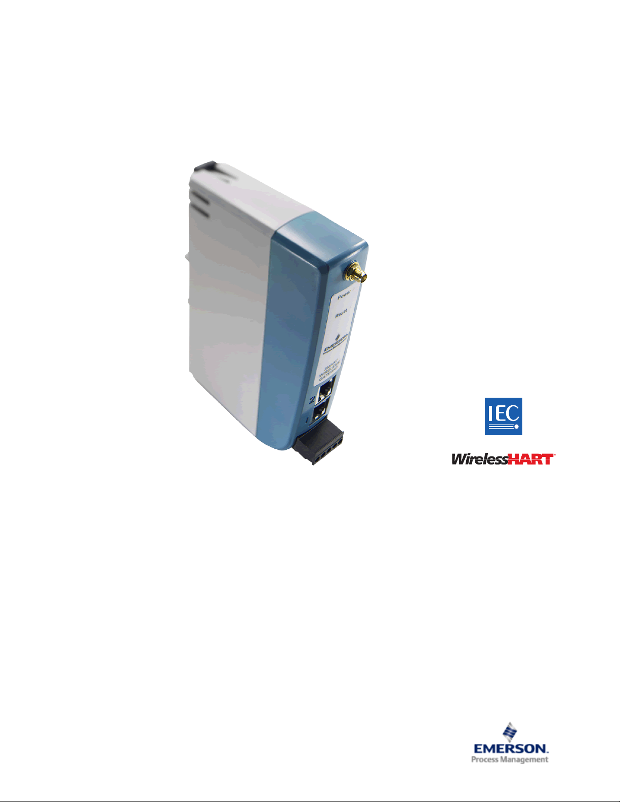
Emerson Smart Wireless Gateway 1410
August 2014
Gateway connects the WirelessHART
Easy configuration and management of self-organizing networks
Easy integration into control systems and data applications through serial and Ethernet connections
Seamless integration into AMS
Greater than 99% data reliability with industry proven security
Smart Wireless capabilities extends the full benefits of PlantWeb
®
self-organizing networks with any host system
®
Device Manager
®
architecture to previously
inaccessible locations
Page 2

Smart Wireless Gateway 1410
August 2014
Emerson Smart Wireless Gateway 1410
Gain real-time process information with greater than 99% wireless
data reliability
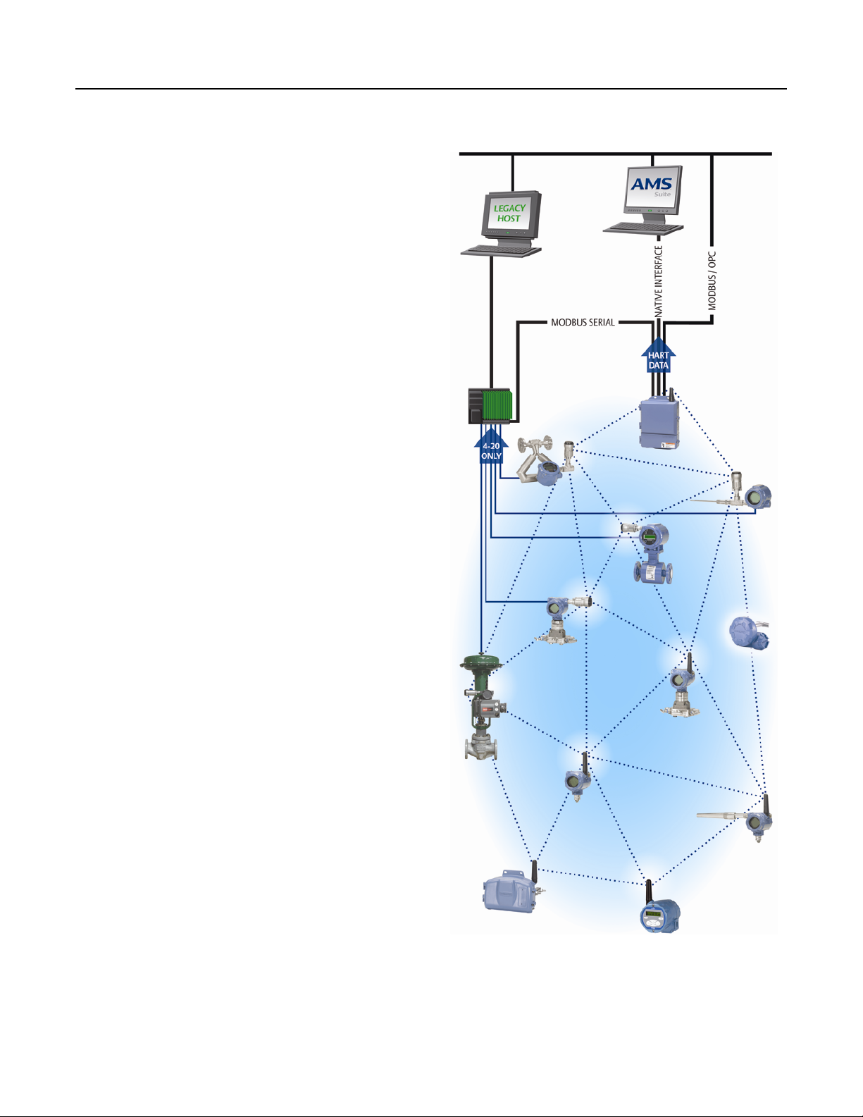
The Emerson Smart Wireless Gateway 1410 automatically manages wireless communications in
constantly changing environments
Native integration with Ovation automation system provides simple and fast commissioning for wireless
field networks
Connect to data historians, legacy host systems, and other applications through Ethernet, Modbus
Serial, OPC, EtherNet/IP, and HART
®
outputs
Complete wireless network configuration tools
provided with each Emerson Smart Wireless
Gateway 1410
®
,
The integrated web interface allows easy configuration of the wireless
network and data integration without the need to install additional
software
Complimentary AMS Wireless Configurator software provides Emerson
Device Dashboards to configure devices and view diagnostic data
Drag and drop device provisioning enables a
secure method to add new wireless devices to
the wireless field network
Contents
Emerson’s Smart Wireless Solution . . . . . . . . . . . . . . . . . . . 3
Functional specifications . . . . . . . . . . . . . . . . . . . . . . . . . . . 6
Physical specifications . . . . . . . . . . . . . . . . . . . . . . . . . . . . . 6
2
Product Certifications . . . . . . . . . . . . . . . . . . . . . . . . . . . . . 8
Dimensional Drawings . . . . . . . . . . . . . . . . . . . . . . . . . . . .9
Page 3
August 2014
Emerson’s Smart Wireless Solution
IEC 62591 (WirelessHART)... the industry
standard
Self-organizing, adaptive mesh routing
No wireless expertise required, network automatically finds
the best communication paths.
The self-organizing, self-healing network manages multiple
communication paths for any given device. If an obstruction is
introduced into the network, data will continue to flow
because the device already has other established paths. The
network will then lay in more communication paths as needed
for that device.
Reliable wireless architecture
Standard IEEE 802.15.4 radios.
2.4 GHz ISM band sliced into 15 radio-channels.
Smart Wireless Gateway 1410
Time Synchronized Channel Hopping to avoid interference
from other radios, Wi-Fi, and EMC sources and increase
reliability.
Direct sequence spread spectrum (DSSS) technology delivers
high reliability in challenging radio environment.
Emerson’s Smart Wireless
Seamless integration to all existing host systems
Native integration into Ovation is transparent and seamless.
Gateways interface with existing host systems using industry
standard protocols including OPC, Modbus TCP/IP, and
Modbus RTU.
Layered security keeps your network safe
Ensures that data transmissions are received only by the
Smart Wireless Gateway.
Network devices implement industry standard encryption,
authentication, verification, anti-jamming, and key
management.
Third party security verification including Achilles and
FIPS197.
3
Page 4

Smart Wireless Gateway 1410
August 2014
Ordering Information
Specification and selection of product materials, options, or components must be made by the purchaser of the equipment. See
page 6 for more information on Material Selection.
Table 1. Smart Wireless Gateway Ordering Information
★ The Standard offering represents the most common options. The starred options (★) should be selected for best delivery.
__The Expanded offering is subject to additional delivery lead time.
Model Product description
1410 Smart Wireless Gateway, 2.4 GHz DSSS, WirelessHART, Webserver, AMS Ready, HART IP ★
Wireless configuration
A 25 Device Network (10.5-30 VDC) ★
Ethernet communications - physical connection
(1)(2)
1
(3)(4)
2
Serial communication
Single Ethernet Connection ★
Dual Ethernet Connection ★
N None ★
(5)
A
Ethernet communication - data protocols
D1 Modbus TCP/IP ★
D2 OPC ★
D3 EtherNet/IP ★
(6)
D4
(6)
D5
(6)
D6
E2 Ovation Ready ★
(7)
E3
Antenna options
WX2 Basic Antenna ★
WL2 SMA-to-N-Type Adapter Cable, and Remote Antenna Kit ★
WN2
Modbus RTU via RS-485 ★
(6)
Modbus TCP/IP, OPC ★
EtherNet/IP, Modbus TCP/IP ★
EtherNet/IP, OPC ★
Webserver Only ★
(8)
(9)
SMA-to-N-Type Adapter Cable, and High-Gain Remote Antenna Kit ★
Product certifications
NA No Approvals ★
N5 FM Division 2, Non-incendive ★
N6 CSA Division 2 (Suitable for Canada and the United States) ★
NM Technical Regulation Customs Union (EAC) Type N ★
4
Page 5

August 2014
Smart Wireless Gateway 1410
Table 1. Smart Wireless Gateway Ordering Information
★ The Standard offering represents the most common options. The starred options (★) should be selected for best delivery.
__The Expanded offering is subject to additional delivery lead time.
Options (Include with selected model number)
Host integration
(10)
H6 Allen Bradley Documentation ★
H9 Other ★
Oil and gas options
G Oil and Gas Monitor Page ★
Typical model number: 1410 A 2 A D4 WX2 N6
(1) Single active 10/100 baseT Ethernet port with RJ45 connector.
(2) Additional ports disabled.
(3) Dual active 10/100 baseT Ethernet ports with RJ45 connectors.
(4) Multiple active ports have separate IP addresses, firewall isolation, and no packet forwarding.
(5) Convertible to RS232 via adapter, not included with Gateway.
(6) Select ion of Dual Ethernet option code 2 is recommended.
(7) Requires (A) Modbus RTU via RS-485 Communication protocol.
(8) The WL2 and WN2 options require minor assembly.
(9) Not available in all countries.
(10) Support documentation included in the package.
Accessories and Spare Parts
Table 2. Spare Parts
Item description Part number
Spare Kit, WL2 Replacement
Remote Antenna, 50 ft. (15,2 m) Cable, and Lightning Arrester
Spare Kit, WN2 Replacement
High Gain, Remote Antenna, 25 ft. (7.6 m) Cable, and Lightning Arrester
(1) Can not upgrade from integral to remote antenna.
(2) Not available in all countries.
(1)
(2)
,
,
01420-1615-0302
01420-1615-0402
5
Page 6

Smart Wireless Gateway 1410
12 24
30
125
250
Voltage (VDC)
Current (mA)
Operating
Region
Product Specifications
August 2014
Functional specifications
Input voltage
10.5-30 VDC
Current draw
Operating Current Draw is based on 3 Watt power consumption.
Radio frequency power output from antenna
Maximum of 10 mW (10 dBm) EIRP
Maximum of 40 mW (16 dBm) EIRP for WN2 High Gain option
Environmental
(1)
Physical specifications
Material selection
Emerson provides a variety of Rosemount product with various
product options and configurations including materials of
construction that can be expected to perform well in a wide
range of applications. The Rosemount product information
presented is intended as a guide for the purchaser to make an
appropriate selection for the application. It is the purchaser’s
sole responsibility to make a careful analysis of all process
parameters (such as all chemical components, temperature,
pressure, flow rate, abrasives, contaminants, etc.), when
specifying product, materials, options and components for the
particular application. Emerson Process Management is not in a
position to evaluate or guarantee the compatibility of the
process fluid or other process parameters with the product,
options, configuration or materials of construction selected.
Weight
0.70 lb. (0,318 kg)
Material of construction
Housing
Polycarbonate
Operating Temperature Range:
-40 to 167 °F (-40 to 75 °C)
Operating Humidity Range:
0-100% relative humidity
EMC performance
Complies with EN61326-1:2006.
Antenna options
Optional remote mount Omni-directional Antenna
Antenna
2 dBi rubber dipole with SMA male connector
SMA connection is female
(1) Not available in all countries.
6
Rail mount
Top hat rail EN 50022 35 mm X 7.5 mm and 35 mm x 15 mm
Communication specifications
Isolated RS-485
2-wire communication link for Modbus RTU multi-drop
connections
Baud rate: 57600, 38400, 19200, or 9600
Protocol: Modbus RTU
Wiring: Single twisted shielded pair, 18 AWG. Wiring distance is
approximately 4000 ft. (1,524 m)
Ethernet
10/100base-TX Ethernet communication port
Protocols: Modbus TCP, OPC, EtherNet/IP, HART-IP, https (for
Web Interface)
Wiring: Cat5E shielded cable. Wiring distance 328 ft. (100 m).
Page 7

August 2014
Smart Wireless Gateway 1410
Modbus
Supports Modbus RTU and Modbus TCP with 32-bit floating
point values, integers, and scaled integers.
Modbus Registers are user-specified.
OPC
OPC server supports OPC DA v2, v3
EtherNet/IP
Supports EtherNet/IP protocol with 32 bit Floating Point values
and Integers. EtherNet/IP Assembly Input-Output instances are
user configurable. EtherNet/IP specifications are managed and
distributed by ODVA. For details on capabilities please see the
Smart Wireless Gateway to Allen Bradley Integration Manual
(Document No. 00809-0500-4420) on Rosemount.com.
Self-organizing network specifications
Protocol
IEC 62591(WirelessHART), 2.4 - 2.5 GHz DSSS.
Maximum network size
Self-organizing network
AES-128 Encrypted WirelessHART, including individual session
keys. Drag and Drop device provisioning, including unique join
keys and white listing.
Internal firewall
User Configurable TCP ports for communications protocols,
including Enable/Disable and user specified port numbers.
Inspects both incoming and outgoing packets.
Third party certification
Wurldtech: Achilles Level 1 certified for network resiliency
National Institute of Standards and Technology (NIST):
Advanced Encryption Standard (AES) Algorithm conforming to
Federal Information Processing Standard Publication 197
(FIPS-197).
25 wireless devices @ 2 sec. or greater
12 wireless devices @ 1 sec.
Supported device update rates
1, 2, 4, 8, 16, 32 seconds or 1 - 60 minutes
For information on network size and update rate, please see the
capacity estimator tool on the Smart Wireless homepage by
following the link: http://www.emersonprocess.com/Wireless.
Network size/latency
25 Devices: less than 5 seconds
Data reliability
Greater than 99%
System security specifications
Ethernet
Secure Sockets Layer (SSL) enabled (default) TCP/IP
communications
Emerson Smart Wireless Gateway access
Role-based Access Control (RBAC) including Administrator,
Maintenance, Operator, and Executive. Administrator has
complete control of the Gateway and connections to host
systems and the self-organizing network.
7
Page 8

Smart Wireless Gateway 1410
Product Certifications
August 2014
Approved Manufacturing Locations
Rosemount Inc. – Chanhassen, Minnesota, USA
Emerson Process Management Asia Pacific Private Limited Singapore
Telecommunication Compliance
All wireless devices require certification to ensure they adhere to
regulations regarding the use of the RF spectrum. Nearly every
country requires this type of product certification. Emerson is
working with governmental agencies around the world to
supply fully compliant products and remove the risk of violating
country directives or laws governing wireless device usage.
FCC and IC
This device complies with Part 15 of the FCC Rules. Operation is
subject to the following conditions: This device may not cause
harmful interference. This device must accept any interference
received, including interference that may cause undesired
operation. This device must be installed to ensure a minimum
antenna separation distance of 20 cm from all persons.
European Directive Information
The EC declaration of conformity can be found in the Quick Start
Guide (00825-0200-4410). The most recent revision can be
found at www.emersonprocess.com.
Ordinary Location Certification from FM
Approvals
As standard, the transmitter has been examined and tested to
determine that the design meets basic electrical, mechanical,
and fire protection requirements by FM Approvals, a nationally
recognized testing laboratory (NRTL) as accredited by the
Federal Occupational Safety and Health Administration (OSHA).
Hazardous Locations Certifications
North American Certifications
N5 FM Approvals, Nonincendive for Class I Division 2
Certificate No.: 3049590
Standards Used:Class 3600:2011, Class 3611:2004, Class
3810:2005
Markings: NI CL I, DIV. 2, GP A, B, C, D
Temperature code: T4 (-40 °C ≤ Ta ≤ 60 °C)
Special Condition of Use:
1. When installed as Division 2 equipment, the 1410 shall be
mounted within a tool-secured enclosure which meets the
requirements of ANSI/ISA 61010-1 and be capable of
accepting the applicable wiring methods per the NEC.
N6 CSA Class I Division 2
Certificate No.: 2646342
Standards Used: CSA Std. C22.2 No. 0-10, CSA Std. C22.2
No. 213 - M1987, CSA Std. C22.2 No.61010-1-12,
ANSI/ISA 12.12.01-2012, ANSI/ISA 61010-1-2012
Markings: SUITABLE FOR CL I, DIV. 2, GP A, B, C, D
Temperature code: T4 (-40 °C ≤ Ta ≤ 70 °C)
NM Technical Regulation Customs Union (EAC)
Contact an Emerson process management representative
for additional information.
Notes
- Shall be powered by a class 2 power supply.
- Suitable for dry indoor locations only.
- Equipment must be installed in a suitable tool accessible
enclosure subject to the end use application.
8
Page 9

August 2014
Dimensional Drawings
Figure 1. Smart Wireless Gateway
Smart Wireless Gateway 1410
* Dimensions are in inches (millimeters)
RF connector on 1410
is an SMA female.
Matching RF cable to
antenna should be a
SMA male.
NOTE: Allow extra
space in front of unit
for wiring, antenna
connector and
antenna cable service
loop.
9
Page 10

Smart Wireless Gateway 1410
A
50 ft. (15,2 m)
cable
WL2WL2
A
25 ft. (7,6 m)
cable
WN2WN2
B
B
Figure 2. WX2 Basic Antenna Dimensions
Figure 3. Remote Omni-Antenna Kit
The Remote Omni-Antenna kit includes sealant tape for remote antenna connection, SMA to N-type adapter cable, mounting
brackets for the antenna, and lightning arrester.
August 2014
A. Antenna
B. Lightning Arrestor
10
Page 11

August 2014
Figure 4. SMA to N-Type Adapter Cable Dimensions
* Dimensions are in inches (millimeters)
Smart Wireless Gateway 1410
11
Page 12

Smart Wireless Gateway 1410
00813-0200-4410, Rev CA
Product Data Sheet
August 2014
Emerson Process Management
Rosemount Inc.
8200 Market Boulevard
Chanhassen, MN 55317 USA
T (U.S.) 1-800-999-9307
T (International) (952) 906-8888
F (952) 906-8809
www.rosemount.com
Emerson Process Management
Asia Pacific Pte Ltd
1 Pandan Crescent
Singapore 128461
T +65 6777 8211
F +65 6777 0947
Service Support Hotline: +65 6770 8711
Email: Enquiries@AP.EmersonProcess.com
www.rosemount.com
Standard Terms and Conditions of Sale can be found at www.rosemount.com\terms_of_sale
The Emerson logo is a trade mark and service mark of Emerson Electric Co.
Rosemount, AMS, and the Rosemount logotype are registered trademarks of Rosemount Inc.
PlantWeb is a registered trademark of one of the Emerson Process Management group of companies.
HART and WirelessHART are registered trademarks of the HART Communication Foundation
Modbus is a trademark of Modicon, Inc.
All other marks are the property of their respective owners.
© 2014 Rosemount Inc. All rights reserved.
Emerson Process Management
Blegistrasse 23
P.O. Box 1046
CH 6341 Baar
Switzerland
T +41 (0) 41 768 6111
F +41 (0) 41 768 6300
www.rosemount.com
Emerson Process Management
Latin America
1300 Concord Terrace, Suite 400
Sunrise Florida 33323 USA
Tel + 1 954 846 5030
www.rosemount.com
00813-0200-4410, Rev CA, 08/14
 Loading...