

Page 1

Reference Manual
00809-0100-4002, Rev DA
May 2017
Rosemount™ DP Level Transmitters and 1199
Diaphragm Seal Systems
Page 2

Page 3

Reference Manual
00809-0100-4002, Rev DA
Contents
1Section 1: Introduction
1.1 Using this manual. . . . . . . . . . . . . . . . . . . . . . . . . . . . . . . . . . . . . . . . . . . . . . . . . . . . . . . . . . . . . . . . . . . . . 1
1.2 Product recycling/disposal. . . . . . . . . . . . . . . . . . . . . . . . . . . . . . . . . . . . . . . . . . . . . . . . . . . . . . . . . . . . . 1
2Section 2: Understanding Remote Seal Systems
2.1 DP Level and remote seal system measurement . . . . . . . . . . . . . . . . . . . . . . . . . . . . . . . . . . . . . . . . . . 3
2.2 Terminology of system components . . . . . . . . . . . . . . . . . . . . . . . . . . . . . . . . . . . . . . . . . . . . . . . . . . . . 3
2.3 Understanding seal system performance . . . . . . . . . . . . . . . . . . . . . . . . . . . . . . . . . . . . . . . . . . . . . . . . 4
Contents
May 2017
2.3.1 Volume temperature effects (process temperature effects) . . . . . . . . . . . . . . . . . . . . . . . . . 4
2.3.2 Density temperature effects (head temperature effects). . . . . . . . . . . . . . . . . . . . . . . . . . . . 5
2.3.3 System time response and performance . . . . . . . . . . . . . . . . . . . . . . . . . . . . . . . . . . . . . . . . . . 5
2.4 Balanced vs. Tuned-System assemblies. . . . . . . . . . . . . . . . . . . . . . . . . . . . . . . . . . . . . . . . . . . . . . . . . . 7
2.5 Specifying the right solution for vacuum applications . . . . . . . . . . . . . . . . . . . . . . . . . . . . . . . . . . . . . 8
2.5.1 Vacuum application overview . . . . . . . . . . . . . . . . . . . . . . . . . . . . . . . . . . . . . . . . . . . . . . . . . . . 8
2.5.2 Vacuum applications . . . . . . . . . . . . . . . . . . . . . . . . . . . . . . . . . . . . . . . . . . . . . . . . . . . . . . . . . . . 8
2.5.3 Seal system construction for vacuum applications . . . . . . . . . . . . . . . . . . . . . . . . . . . . . . . . . 8
2.5.4 Transmitter mounting position . . . . . . . . . . . . . . . . . . . . . . . . . . . . . . . . . . . . . . . . . . . . . . . . . . 8
2.5.5 Fill fluid selection . . . . . . . . . . . . . . . . . . . . . . . . . . . . . . . . . . . . . . . . . . . . . . . . . . . . . . . . . . . . . . 8
2.6 Diaphragm weld types . . . . . . . . . . . . . . . . . . . . . . . . . . . . . . . . . . . . . . . . . . . . . . . . . . . . . . . . . . . . . . . . 9
2.6.1 Solid faceplate design . . . . . . . . . . . . . . . . . . . . . . . . . . . . . . . . . . . . . . . . . . . . . . . . . . . . . . . . . . 9
2.6.2 Seam weld design. . . . . . . . . . . . . . . . . . . . . . . . . . . . . . . . . . . . . . . . . . . . . . . . . . . . . . . . . . . . . . 9
2.6.3 Brazed design . . . . . . . . . . . . . . . . . . . . . . . . . . . . . . . . . . . . . . . . . . . . . . . . . . . . . . . . . . . . . . . . . 9
2.7 Differences between electronic remote sensors and capillary systems. . . . . . . . . . . . . . . . . . . . . . 10
2.8 Instrument Toolkit: seal ordering and application process . . . . . . . . . . . . . . . . . . . . . . . . . . . . . . . . 10
2.9 Rosemount Thermal Range Expander: proper use and applications . . . . . . . . . . . . . . . . . . . . . . . . 11
2.10 Thermal optimizer: proper use and applications . . . . . . . . . . . . . . . . . . . . . . . . . . . . . . . . . . . . . . . . .12
2.10.1 Thermal optimizer limitations . . . . . . . . . . . . . . . . . . . . . . . . . . . . . . . . . . . . . . . . . . . . . . . . . .13
2.11 Submersible seal . . . . . . . . . . . . . . . . . . . . . . . . . . . . . . . . . . . . . . . . . . . . . . . . . . . . . . . . . . . . . . . . . . . . 13
2.11.1 Designed for top-down measurement . . . . . . . . . . . . . . . . . . . . . . . . . . . . . . . . . . . . . . . . . . . 13
Content s
2.11.2 Submersible Seal features. . . . . . . . . . . . . . . . . . . . . . . . . . . . . . . . . . . . . . . . . . . . . . . . . . . . . . 14
3Section 3: Installation
3.1 Seals handling and installation . . . . . . . . . . . . . . . . . . . . . . . . . . . . . . . . . . . . . . . . . . . . . . . . . . . . . . . . 15
3.1.1 Diaphragm. . . . . . . . . . . . . . . . . . . . . . . . . . . . . . . . . . . . . . . . . . . . . . . . . . . . . . . . . . . . . . . . . . . 15
3.1.2 Capillary . . . . . . . . . . . . . . . . . . . . . . . . . . . . . . . . . . . . . . . . . . . . . . . . . . . . . . . . . . . . . . . . . . . . . 16
1
Page 4

Contents
May 2017
Reference Manual
00809-0100-4002, Rev DA
3.1.3 Rosemount Thermal Range Expander. . . . . . . . . . . . . . . . . . . . . . . . . . . . . . . . . . . . . . . . . . . 16
3.1.4 Heat tracing . . . . . . . . . . . . . . . . . . . . . . . . . . . . . . . . . . . . . . . . . . . . . . . . . . . . . . . . . . . . . . . . . 16
3.2 Gaskets . . . . . . . . . . . . . . . . . . . . . . . . . . . . . . . . . . . . . . . . . . . . . . . . . . . . . . . . . . . . . . . . . . . . . . . . . . . . 17
3.3 Tagging. . . . . . . . . . . . . . . . . . . . . . . . . . . . . . . . . . . . . . . . . . . . . . . . . . . . . . . . . . . . . . . . . . . . . . . . . . . . 18
3.3.1 Max working pressure. . . . . . . . . . . . . . . . . . . . . . . . . . . . . . . . . . . . . . . . . . . . . . . . . . . . . . . . . 18
3.4 FFW flush flanged seal . . . . . . . . . . . . . . . . . . . . . . . . . . . . . . . . . . . . . . . . . . . . . . . . . . . . . . . . . . . . . . . 19
3.4.1 Parts required for installation . . . . . . . . . . . . . . . . . . . . . . . . . . . . . . . . . . . . . . . . . . . . . . . . . . 27
3.4.2 Installation steps . . . . . . . . . . . . . . . . . . . . . . . . . . . . . . . . . . . . . . . . . . . . . . . . . . . . . . . . . . . . . 28
3.5 RFW off-line flanged seal . . . . . . . . . . . . . . . . . . . . . . . . . . . . . . . . . . . . . . . . . . . . . . . . . . . . . . . . . . . . . 29
3.5.1 4.1-in. (104 mm) diaphragm diameter option . . . . . . . . . . . . . . . . . . . . . . . . . . . . . . . . . . . 32
3.5.2 Parts required for installation . . . . . . . . . . . . . . . . . . . . . . . . . . . . . . . . . . . . . . . . . . . . . . . . . . 32
3.5.3 Installation steps . . . . . . . . . . . . . . . . . . . . . . . . . . . . . . . . . . . . . . . . . . . . . . . . . . . . . . . . . . . . . 32
3.6 EFW extended flanged seal . . . . . . . . . . . . . . . . . . . . . . . . . . . . . . . . . . . . . . . . . . . . . . . . . . . . . . . . . . . 33
3.6.1 Parts required for installation . . . . . . . . . . . . . . . . . . . . . . . . . . . . . . . . . . . . . . . . . . . . . . . . . . 41
3.6.2 Installation steps . . . . . . . . . . . . . . . . . . . . . . . . . . . . . . . . . . . . . . . . . . . . . . . . . . . . . . . . . . . . . 41
3.7 PFW pancake seal . . . . . . . . . . . . . . . . . . . . . . . . . . . . . . . . . . . . . . . . . . . . . . . . . . . . . . . . . . . . . . . . . . . 42
3.7.1 Capillary support tube . . . . . . . . . . . . . . . . . . . . . . . . . . . . . . . . . . . . . . . . . . . . . . . . . . . . . . . . 43
3.7.2 Process flange . . . . . . . . . . . . . . . . . . . . . . . . . . . . . . . . . . . . . . . . . . . . . . . . . . . . . . . . . . . . . . . 44
3.7.3 Parts required for installation . . . . . . . . . . . . . . . . . . . . . . . . . . . . . . . . . . . . . . . . . . . . . . . . . . 44
3.7.4 Installation steps . . . . . . . . . . . . . . . . . . . . . . . . . . . . . . . . . . . . . . . . . . . . . . . . . . . . . . . . . . . . . 44
3.8 FCW flush flanged seal—ring type joint (RTJ) gasket surface . . . . . . . . . . . . . . . . . . . . . . . . . . . . . . 45
3.8.1 Parts required for installation . . . . . . . . . . . . . . . . . . . . . . . . . . . . . . . . . . . . . . . . . . . . . . . . . . 47
3.8.2 Installation steps . . . . . . . . . . . . . . . . . . . . . . . . . . . . . . . . . . . . . . . . . . . . . . . . . . . . . . . . . . . . . 47
3.9 RCW off-line ring type joint (RTJ) flanged seal. . . . . . . . . . . . . . . . . . . . . . . . . . . . . . . . . . . . . . . . . . . 48
3.9.1 4.1-in. (104 mm) diaphragm diameter option . . . . . . . . . . . . . . . . . . . . . . . . . . . . . . . . . . . 49
3.9.2 Parts required for installation . . . . . . . . . . . . . . . . . . . . . . . . . . . . . . . . . . . . . . . . . . . . . . . . . . 49
3.9.3 Installation steps . . . . . . . . . . . . . . . . . . . . . . . . . . . . . . . . . . . . . . . . . . . . . . . . . . . . . . . . . . . . . 49
3.10 FUW flush flanged groove type seals. . . . . . . . . . . . . . . . . . . . . . . . . . . . . . . . . . . . . . . . . . . . . . . . . . . 50
3.10.1 Parts required for installation . . . . . . . . . . . . . . . . . . . . . . . . . . . . . . . . . . . . . . . . . . . . . . . . . . 50
3.10.2 Installation steps . . . . . . . . . . . . . . . . . . . . . . . . . . . . . . . . . . . . . . . . . . . . . . . . . . . . . . . . . . . . . 50
3.11 FVW flush flanged tongue type seals . . . . . . . . . . . . . . . . . . . . . . . . . . . . . . . . . . . . . . . . . . . . . . . . . . 51
3.11.1 Parts required for installation . . . . . . . . . . . . . . . . . . . . . . . . . . . . . . . . . . . . . . . . . . . . . . . . . . 52
3.11.2 Installation steps . . . . . . . . . . . . . . . . . . . . . . . . . . . . . . . . . . . . . . . . . . . . . . . . . . . . . . . . . . . . . 52
3.12 RTW off-line threaded type seals . . . . . . . . . . . . . . . . . . . . . . . . . . . . . . . . . . . . . . . . . . . . . . . . . . . . . . 53
3.12.1 Parts required for installation . . . . . . . . . . . . . . . . . . . . . . . . . . . . . . . . . . . . . . . . . . . . . . . . . . 54
3.12.2 Installation steps . . . . . . . . . . . . . . . . . . . . . . . . . . . . . . . . . . . . . . . . . . . . . . . . . . . . . . . . . . . . . 54
3.13 HTS male threaded seal. . . . . . . . . . . . . . . . . . . . . . . . . . . . . . . . . . . . . . . . . . . . . . . . . . . . . . . . . . . . . . 55
3.13.1 Parts required for installation . . . . . . . . . . . . . . . . . . . . . . . . . . . . . . . . . . . . . . . . . . . . . . . . . . 55
2
Contents
Page 5

Reference Manual
00809-0100-4002, Rev DA
3.14 SCW hygienic Tri-Clover Tri Clamp seals . . . . . . . . . . . . . . . . . . . . . . . . . . . . . . . . . . . . . . . . . . . . . . . . 56
3.15 SSW hygienic tank spud seal . . . . . . . . . . . . . . . . . . . . . . . . . . . . . . . . . . . . . . . . . . . . . . . . . . . . . . . . . .58
3.16 STW hygienic thin wall tank spud seal . . . . . . . . . . . . . . . . . . . . . . . . . . . . . . . . . . . . . . . . . . . . . . . . . . 61
3.17 EES hygienic flanged tank spud extended seal . . . . . . . . . . . . . . . . . . . . . . . . . . . . . . . . . . . . . . . . . . . 62
Contents
May 2017
3.13.2 Installation steps. . . . . . . . . . . . . . . . . . . . . . . . . . . . . . . . . . . . . . . . . . . . . . . . . . . . . . . . . . . . . . 56
3.14.1 Clamp and gasket. . . . . . . . . . . . . . . . . . . . . . . . . . . . . . . . . . . . . . . . . . . . . . . . . . . . . . . . . . . . . 57
3.14.2 Parts required for installation . . . . . . . . . . . . . . . . . . . . . . . . . . . . . . . . . . . . . . . . . . . . . . . . . . . 57
3.14.3 Installation steps. . . . . . . . . . . . . . . . . . . . . . . . . . . . . . . . . . . . . . . . . . . . . . . . . . . . . . . . . . . . . . 57
3.15.1 Parts required for installation . . . . . . . . . . . . . . . . . . . . . . . . . . . . . . . . . . . . . . . . . . . . . . . . . . . 58
3.15.2 Installation steps. . . . . . . . . . . . . . . . . . . . . . . . . . . . . . . . . . . . . . . . . . . . . . . . . . . . . . . . . . . . . . 58
3.15.3 Tank preparation . . . . . . . . . . . . . . . . . . . . . . . . . . . . . . . . . . . . . . . . . . . . . . . . . . . . . . . . . . . . . 59
3.15.4 Welding . . . . . . . . . . . . . . . . . . . . . . . . . . . . . . . . . . . . . . . . . . . . . . . . . . . . . . . . . . . . . . . . . . . . .60
3.16.1 Parts required for installation . . . . . . . . . . . . . . . . . . . . . . . . . . . . . . . . . . . . . . . . . . . . . . . . . . . 61
3.16.2 Installation steps. . . . . . . . . . . . . . . . . . . . . . . . . . . . . . . . . . . . . . . . . . . . . . . . . . . . . . . . . . . . . . 61
3.17.1 Parts required for installation . . . . . . . . . . . . . . . . . . . . . . . . . . . . . . . . . . . . . . . . . . . . . . . . . . . 62
3.17.2 Installation steps. . . . . . . . . . . . . . . . . . . . . . . . . . . . . . . . . . . . . . . . . . . . . . . . . . . . . . . . . . . . . . 62
3.18 VCS Tri Clamp In-line seal . . . . . . . . . . . . . . . . . . . . . . . . . . . . . . . . . . . . . . . . . . . . . . . . . . . . . . . . . . . . . 63
3.18.1 Parts required for installation . . . . . . . . . . . . . . . . . . . . . . . . . . . . . . . . . . . . . . . . . . . . . . . . . . . 63
3.18.2 Installation steps. . . . . . . . . . . . . . . . . . . . . . . . . . . . . . . . . . . . . . . . . . . . . . . . . . . . . . . . . . . . . . 63
3.19 SVS VARIVENT compatible hygienic connection seal. . . . . . . . . . . . . . . . . . . . . . . . . . . . . . . . . . . . 64
3.19.1 Parts required for installation . . . . . . . . . . . . . . . . . . . . . . . . . . . . . . . . . . . . . . . . . . . . . . . . . . . 64
3.19.2 Installation steps. . . . . . . . . . . . . . . . . . . . . . . . . . . . . . . . . . . . . . . . . . . . . . . . . . . . . . . . . . . . . . 64
3.20 SHP hygienic Cherry-Burrell “I” line seal . . . . . . . . . . . . . . . . . . . . . . . . . . . . . . . . . . . . . . . . . . . . . . . . 65
3.20.1 Parts required for installation . . . . . . . . . . . . . . . . . . . . . . . . . . . . . . . . . . . . . . . . . . . . . . . . . . . 65
3.20.2 Installation steps. . . . . . . . . . . . . . . . . . . . . . . . . . . . . . . . . . . . . . . . . . . . . . . . . . . . . . . . . . . . . . 66
3.21 SLS dairy process connection–female thread seal per DIN 11851 . . . . . . . . . . . . . . . . . . . . . . . . . . 66
3.21.1 Parts required for installation . . . . . . . . . . . . . . . . . . . . . . . . . . . . . . . . . . . . . . . . . . . . . . . . . . . 66
3.21.2 Installation steps. . . . . . . . . . . . . . . . . . . . . . . . . . . . . . . . . . . . . . . . . . . . . . . . . . . . . . . . . . . . . . 67
3.22 WSP saddle seal . . . . . . . . . . . . . . . . . . . . . . . . . . . . . . . . . . . . . . . . . . . . . . . . . . . . . . . . . . . . . . . . . . . . . 67
3.22.1 Parts required for installation . . . . . . . . . . . . . . . . . . . . . . . . . . . . . . . . . . . . . . . . . . . . . . . . . . . 68
3.22.2 Installation steps. . . . . . . . . . . . . . . . . . . . . . . . . . . . . . . . . . . . . . . . . . . . . . . . . . . . . . .
3.23 UCP union connection pipe mount seal. . . . . . . . . . . . . . . . . . . . . . . . . . . . . . . . . . . . . . . . . . . . . . . . . 69
3.23.1 Parts required for installation . . . . . . . . . . . . . . . . . . . . . . . . . . . . . . . . . . . . . . . . . . . . . . . . . . . 69
3.23.2 Installation steps. . . . . . . . . . . . . . . . . . . . . . . . . . . . . . . . . . . . . . . . . . . . . . . . . . . . . . . . . . . . . . 69
. . . . . . . 68
Content s
3.24 PMW paper mill sleeve seal . . . . . . . . . . . . . . . . . . . . . . . . . . . . . . . . . . . . . . . . . . . . . . . . . . . . . . . . . . .71
3.24.1 Parts required for installation . . . . . . . . . . . . . . . . . . . . . . . . . . . . . . . . . . . . . . . . . . . . . . . . . . . 71
3.24.2 Installation steps. . . . . . . . . . . . . . . . . . . . . . . . . . . . . . . . . . . . . . . . . . . . . . . . . . . . . . . . . . . . . . 71
3.25 CTW chemical tee seal . . . . . . . . . . . . . . . . . . . . . . . . . . . . . . . . . . . . . . . . . . . . . . . . . . . . . . . . . . . . . . . 73
3
Page 6

Contents
May 2017
Reference Manual
00809-0100-4002, Rev DA
3.25.1 Parts required for installation . . . . . . . . . . . . . . . . . . . . . . . . . . . . . . . . . . . . . . . . . . . . . . . . . . 73
3.25.2 Installation steps . . . . . . . . . . . . . . . . . . . . . . . . . . . . . . . . . . . . . . . . . . . . . . . . . . . . . . . . . . . . . 73
3.26 TFS wafer style In-line seal. . . . . . . . . . . . . . . . . . . . . . . . . . . . . . . . . . . . . . . . . . . . . . . . . . . . . . . . . . . . 74
3.26.1 Parts required for installation . . . . . . . . . . . . . . . . . . . . . . . . . . . . . . . . . . . . . . . . . . . . . . . . . . 74
3.26.2 Installation steps . . . . . . . . . . . . . . . . . . . . . . . . . . . . . . . . . . . . . . . . . . . . . . . . . . . . . . . . . . . . . 74
3.27 WFW flow-thru flanged seal . . . . . . . . . . . . . . . . . . . . . . . . . . . . . . . . . . . . . . . . . . . . . . . . . . . . . . . . . . 75
3.27.1 Parts required for installation . . . . . . . . . . . . . . . . . . . . . . . . . . . . . . . . . . . . . . . . . . . . . . . . . . 76
3.27.2 Installation steps . . . . . . . . . . . . . . . . . . . . . . . . . . . . . . . . . . . . . . . . . . . . . . . . . . . . . . . . . . . . . 76
4Section 4: Configuration
4.1 Calculating range points . . . . . . . . . . . . . . . . . . . . . . . . . . . . . . . . . . . . . . . . . . . . . . . . . . . . . . . . . . . . . 77
4.1.1 Remote seals . . . . . . . . . . . . . . . . . . . . . . . . . . . . . . . . . . . . . . . . . . . . . . . . . . . . . . . . . . . . . . . . 77
4.1.2 Zero-based lower range value. . . . . . . . . . . . . . . . . . . . . . . . . . . . . . . . . . . . . . . . . . . . . . . . . . 78
4.1.3 Non-zero based lower range value. . . . . . . . . . . . . . . . . . . . . . . . . . . . . . . . . . . . . . . . . . . . . . 79
4.1.4 Non-zero based lower range value (transmitter mounted above seal). . . . . . . . . . . . . . . 80
4.1.5 Non-zero based lower range value (Tuned-System assembly). . . . . . . . . . . . . . . . . . . . . . 81
4.1.6 Non-zero based lower range value (balanced system with transmitter between seals) 82
4.1.7 Non-zero based lower range value (balanced system with transmitter below seals) . . . 83
4.2 DP Level transmitter installation best practices . . . . . . . . . . . . . . . . . . . . . . . . . . . . . . . . . . . . . . . . . 84
4.2.1 Open tank (zero based) . . . . . . . . . . . . . . . . . . . . . . . . . . . . . . . . . . . . . . . . . . . . . . . . . . . . . . . 84
4.2.2 Closed tank (non-zero based) . . . . . . . . . . . . . . . . . . . . . . . . . . . . . . . . . . . . . . . . . . . . . . . . . . 84
4.2.3 Open tank example (zero-based lower range value) with HART Communicator . . . . . . 85
4.2.4 Closed tank example (non-zero based lower range value) . . . . . . . . . . . . . . . . . . . . . . . . . 85
4.2.5 Scale display with HART Communicator. . . . . . . . . . . . . . . . . . . . . . . . . . . . . . . . . . . . . . . . . 88
5Section 5: Fill Fluids Specifications
5.1 Quality. . . . . . . . . . . . . . . . . . . . . . . . . . . . . . . . . . . . . . . . . . . . . . . . . . . . . . . . . . . . . . . . . . . . . . . . . . . . . 89
5.1.1 Specialized processing . . . . . . . . . . . . . . . . . . . . . . . . . . . . . . . . . . . . . . . . . . . . . . . . . . . . . . . . 89
5.1.2 Testing. . . . . . . . . . . . . . . . . . . . . . . . . . . . . . . . . . . . . . . . . . . . . . . . . . . . . . . . . . . . . . . . . . . . . . 89
5.2 Fill fluid selection. . . . . . . . . . . . . . . . . . . . . . . . . . . . . . . . . . . . . . . . . . . . . . . . . . . . . . . . . . . . . . . . . . . . 89
5.2.1 Type of fill fluid. . . . . . . . . . . . . . . . . . . . . . . . . . . . . . . . . . . . . . . . . . . . . . . . . . . . . . . . . . . . . . . 89
5.2.2 Maximum and minimum temperatures . . . . . . . . . . . . . . . . . . . . . . . . . . . . . . . . . . . . . . . . . 89
5.2.3 Process pressure and temperature . . . . . . . . . . . . . . . . . . . . . . . . . . . . . . . . . . . . . . . . . . . . . 90
5.3 Fill fluids vapor pressure curve graphs . . . . . . . . . . . . . . . . . . . . . . . . . . . . . . . . . . . . . . . . . . . . . . . . . 90
5.3.1 How to use the vapor pressure curves. . . . . . . . . . . . . . . . . . . . . . . . . . . . . . . . . . . . . . . . . . . 90
5.3.2 Fill fluid selection example. . . . . . . . . . . . . . . . . . . . . . . . . . . . . . . . . . . . . . . . . . . . . . . . . . . . . 91
5.3.3 Fill fluid specifications. . . . . . . . . . . . . . . . . . . . . . . . . . . . . . . . . . . . . . . . . . . . . . . . . . . . . . . . . 91
4
Contents
Page 7

Reference Manual
00809-0100-4002, Rev DA
6Section 6: Maintenance and Troubleshooting
6.1 Cleaning. . . . . . . . . . . . . . . . . . . . . . . . . . . . . . . . . . . . . . . . . . . . . . . . . . . . . . . . . . . . . . . . . . . . . . . . . . . . 93
6.2 Troubleshooting. . . . . . . . . . . . . . . . . . . . . . . . . . . . . . . . . . . . . . . . . . . . . . . . . . . . . . . . . . . . . . . . . . . . . 93
6.3 Service support. . . . . . . . . . . . . . . . . . . . . . . . . . . . . . . . . . . . . . . . . . . . . . . . . . . . . . . . . . . . . . . . . . . . . . 95
AAppendix A: Specifications and Reference Data
A.1 Rosemount 1199 Direct Mount Seal Systems. . . . . . . . . . . . . . . . . . . . . . . . . . . . . . . . . . . . . . . . . . . . 97
A.2 Rosemount 1199 Remote Mount Seal Systems . . . . . . . . . . . . . . . . . . . . . . . . . . . . . . . . . . . . . . . . .103
A.3 Dimensional drawings. . . . . . . . . . . . . . . . . . . . . . . . . . . . . . . . . . . . . . . . . . . . . . . . . . . . . . . . . . . . . . .110
A.4 Spare parts . . . . . . . . . . . . . . . . . . . . . . . . . . . . . . . . . . . . . . . . . . . . . . . . . . . . . . . . . . . . . . . . . . . . . . . .115
Contents
May 2017
6.1.1 Return of materials. . . . . . . . . . . . . . . . . . . . . . . . . . . . . . . . . . . . . . . . . . . . . . . . . . . . . . . . . . . . 93
A.1.1 Rosemount 1199 Direct Mount Seal. . . . . . . . . . . . . . . . . . . . . . . . . . . . . . . . . . . . . . . . . . . . . 97
A.2.1 Rosemount 1199 Remote Mount Seal . . . . . . . . . . . . . . . . . . . . . . . . . . . . . . . . . . . . . . . . . .103
A.2.2 Capillary/fill fluid. . . . . . . . . . . . . . . . . . . . . . . . . . . . . . . . . . . . . . . . . . . . . . . . . . . . . . . . . . . . .103
BAppendix B: Product Certifications
B.1 Rosemount 3051S/3051S ERS. . . . . . . . . . . . . . . . . . . . . . . . . . . . . . . . . . . . . . . . . . . . . . . . . . . . . . . .121
B.1.1 European Directive Information . . . . . . . . . . . . . . . . . . . . . . . . . . . . . . . . . . . . . . . . . . . . . . . 121
B.1.2 Ordinary Location Certification . . . . . . . . . . . . . . . . . . . . . . . . . . . . . . . . . . . . . . . . . . . . . . . . 121
B.1.3 Installing Equipment in North America . . . . . . . . . . . . . . . . . . . . . . . . . . . . . . . . . . . . . . . . .121
B.1.4 USA . . . . . . . . . . . . . . . . . . . . . . . . . . . . . . . . . . . . . . . . . . . . . . . . . . . . . . . . . . . . . . . . . . . . . . . . 121
B.1.5 Canada . . . . . . . . . . . . . . . . . . . . . . . . . . . . . . . . . . . . . . . . . . . . . . . . . . . . . . . . . . . . . . . . . . . . .122
B.1.6 Europe . . . . . . . . . . . . . . . . . . . . . . . . . . . . . . . . . . . . . . . . . . . . . . . . . . . . . . . . . . . . . . . . . . . . .122
B.1.7 International . . . . . . . . . . . . . . . . . . . . . . . . . . . . . . . . . . . . . . . . . . . . . . . . . . . . . . . . . . . . . . . .124
B.1.8 Brazil . . . . . . . . . . . . . . . . . . . . . . . . . . . . . . . . . . . . . . . . . . . . . . . . . . . . . . . . . . . . . . . . . . . . . . .126
B.1.9 China. . . . . . . . . . . . . . . . . . . . . . . . . . . . . . . . . . . . . . . . . . . . . . . . . . . . . . . . . . . . . . . . . . . . . . .126
B.1.10 EAC - Belarus, Kazakhstan, Russia . . . . . . . . . . . . . . . . . . . . . . . . . . . . . . . . . . . . . . . . . . . . . .128
B.1.11 Japan . . . . . . . . . . . . . . . . . . . . . . . . . . . . . . . . . . . . . . . . . . . . . . . . . . . . . . . . . . . . . . . . . . . . . . .128
B.1.12 Republic of Korea . . . . . . . . . . . . . . . . . . . . . . . . . . . . . . . . . . . . . . . . . . . . . . . . . . . . . . . . . . . . 128
B.1.13 Combinations . . . . . . . . . . . . . . . . . . . . . . . . . . . . . . . . . . . . . . . . . . . . . . . . . . . . . . . . . . . . . . .129
B.1.14 Additional Certifications . . . . . . . . . . . . . . . . . . . . . . . . . . . . . . . . . . . . . . . . . . . . . . . . . . . . . .129
B.2 Rosemount 3051S Wireless . . . . . . . . . . . . . . . . . . . . . . . . . . . . . . . . . . . . . . . . . . . . . . . . . . . . . . . . . .130
B.2.1 European Directive Information . . . . . . . . . . . . . . . . . . . . . . . . . . . . . . . . . . . . . . . . . . . . . . . 130
Content s
B.2.2 Telecommunication compliance. . . . . . . . . . . . . . . . . . . . . . . . . . . . . . . . . . . . . . . . . . . . . . . 130
B.2.3 FCC and IC . . . . . . . . . . . . . . . . . . . . . . . . . . . . . . . . . . . . . . . . . . . . . . . . . . . . . . . . . . . . . . . . . .130
B.2.4 Ordinary Location Certification . . . . . . . . . . . . . . . . . . . . . . . . . . . . . . . . . . . . . . . . . . . . . . . . 130
B.2.5 Installing Equipment in North America . . . . . . . . . . . . . . . . . . . . . . . . . . . . . . . . . . . . . . . . .130
B.2.6 USA . . . . . . . . . . . . . . . . . . . . . . . . . . . . . . . . . . . . . . . . . . . . . . . . . . . . . . . . . . . . . . . . . . . . . . . . 130
5
Page 8

Contents
May 2017
Reference Manual
00809-0100-4002, Rev DA
B.2.7 Canada. . . . . . . . . . . . . . . . . . . . . . . . . . . . . . . . . . . . . . . . . . . . . . . . . . . . . . . . . . . . . . . . . . . . . 130
B.2.8 Europe . . . . . . . . . . . . . . . . . . . . . . . . . . . . . . . . . . . . . . . . . . . . . . . . . . . . . . . . . . . . . . . . . . . . . 131
B.2.9 International. . . . . . . . . . . . . . . . . . . . . . . . . . . . . . . . . . . . . . . . . . . . . . . . . . . . . . . . . . . . . . . . 131
B.2.10 Brazil . . . . . . . . . . . . . . . . . . . . . . . . . . . . . . . . . . . . . . . . . . . . . . . . . . . . . . . . . . . . . . . . . . . . . . 131
B.2.11 China . . . . . . . . . . . . . . . . . . . . . . . . . . . . . . . . . . . . . . . . . . . . . . . . . . . . . . . . . . . . . . . . . . . . . . 131
B.2.12 Japan . . . . . . . . . . . . . . . . . . . . . . . . . . . . . . . . . . . . . . . . . . . . . . . . . . . . . . . . . . . . . . . . . . . . . . 131
B.2.13 EAC – Belarus, Kazakhstan, Russia . . . . . . . . . . . . . . . . . . . . . . . . . . . . . . . . . . . . . . . . . . . . . 131
B.2.14 Republic of Korea . . . . . . . . . . . . . . . . . . . . . . . . . . . . . . . . . . . . . . . . . . . . . . . . . . . . . . . . . . . 131
B.2.15 Combination . . . . . . . . . . . . . . . . . . . . . . . . . . . . . . . . . . . . . . . . . . . . . . . . . . . . . . . . . . . . . . . 131
B.3 Rosemount 3051 . . . . . . . . . . . . . . . . . . . . . . . . . . . . . . . . . . . . . . . . . . . . . . . . . . . . . . . . . . . . . . . . . . 132
B.3.1 European Directive Information . . . . . . . . . . . . . . . . . . . . . . . . . . . . . . . . . . . . . . . . . . . . . . . 132
B.3.2 Ordinary Location Certification. . . . . . . . . . . . . . . . . . . . . . . . . . . . . . . . . . . . . . . . . . . . . . . . 132
B.3.3 North America . . . . . . . . . . . . . . . . . . . . . . . . . . . . . . . . . . . . . . . . . . . . . . . . . . . . . . . . . . . . . . 132
B.3.4 Europe . . . . . . . . . . . . . . . . . . . . . . . . . . . . . . . . . . . . . . . . . . . . . . . . . . . . . . . . . . . . . . . . . . . . . 133
B.3.5 International. . . . . . . . . . . . . . . . . . . . . . . . . . . . . . . . . . . . . . . . . . . . . . . . . . . . . . . . . . . . . . . . 134
B.3.6 Brazil . . . . . . . . . . . . . . . . . . . . . . . . . . . . . . . . . . . . . . . . . . . . . . . . . . . . . . . . . . . . . . . . . . . . . . 135
B.3.7 China . . . . . . . . . . . . . . . . . . . . . . . . . . . . . . . . . . . . . . . . . . . . . . . . . . . . . . . . . . . . . . . . . . . . . . 136
B.3.8 Japan . . . . . . . . . . . . . . . . . . . . . . . . . . . . . . . . . . . . . . . . . . . . . . . . . . . . . . . . . . . . . . . . . . . . . . 137
B.3.9 Technical Regulations Customs Union (EAC). . . . . . . . . . . . . . . . . . . . . . . . . . . . . . . . . . . . 137
B.3.10 Combinations. . . . . . . . . . . . . . . . . . . . . . . . . . . . . . . . . . . . . . . . . . . . . . . . . . . . . . . . . . . . . . . 138
B.3.11 Conduit Plugs and Adapters . . . . . . . . . . . . . . . . . . . . . . . . . . . . . . . . . . . . . . . . . . . . . . . . . . 138
B.3.12 Additional Certifications . . . . . . . . . . . . . . . . . . . . . . . . . . . . . . . . . . . . . . . . . . . . . . . . . . . . . 138
B.4 Rosemount 2051 . . . . . . . . . . . . . . . . . . . . . . . . . . . . . . . . . . . . . . . . . . . . . . . . . . . . . . . . . . . . . . . . . . 139
B.4.1 European Directive Information . . . . . . . . . . . . . . . . . . . . . . . . . . . . . . . . . . . . . . . . . . . . . . . 139
B.4.2 Ordinary Location Certification. . . . . . . . . . . . . . . . . . . . . . . . . . . . . . . . . . . . . . . . . . . . . . . . 139
B.4.3 North America . . . . . . . . . . . . . . . . . . . . . . . . . . . . . . . . . . . . . . . . . . . . . . . . . . . . . . . . . . . . . . 139
B.4.4 Europe . . . . . . . . . . . . . . . . . . . . . . . . . . . . . . . . . . . . . . . . . . . . . . . . . . . . . . . . . . . . . . . . . . . . . 140
B.4.5 International. . . . . . . . . . . . . . . . . . . . . . . . . . . . . . . . . . . . . . . . . . . . . . . . . . . . . . . . . . . . . . . . 141
B.4.6 Brazil . . . . . . . . . . . . . . . . . . . . . . . . . . . . . . . . . . . . . . . . . . . . . . . . . . . . . . . . . . . . . . . . . . . . . . 142
B.4.7 China . . . . . . . . . . . . . . . . . . . . . . . . . . . . . . . . . . . . . . . . . . . . . . . . . . . . . . . . . . . . . . . . . . . . . . 142
B.4.8 Japan . . . . . . . . . . . . . . . . . . . . . . . . . . . . . . . . . . . . . . . . . . . . . . . . . . . . . . . . . . . . . . . . . . . . . . 144
B.4.9 Technical Regulations Customs Union (EAC). . . . . . . . . . . . . . . . . . . . . . . . . . . . . . . . . . . . 144
B.4.10 Combinations. . . . . . . . . . . . . . . . . . . . . . . . . . . . . . . . . . . . . . . . . . . . . . . . . . . . . . . . . . . . . . . 144
B.4.11 Additional Certifications . . . . . . . . . . . . . . . . . . . . . . . . . . . . . . . . . . . . . . . . . . . . . . . . . . . . . 144
B.5 Rosemount 3051 Wireless . . . . . . . . . . . . . . . . . . . . . . . . . . . . . . . . . . . . . . . . . . . . . . . . . . . .
B.5.1 European Directive Information . . . . . . . . . . . . . . . . . . . . . . . . . . . . . . . . . . . . . . . . . . . . . . . 146
B.5.2 Telecommunication compliance . . . . . . . . . . . . . . . . . . . . . . . . . . . . . . . . . . . . . . . . . . . . . . 146
B.5.3 FCC and IC. . . . . . . . . . . . . . . . . . . . . . . . . . . . . . . . . . . . . . . . . . . . . . . . . . . . . . . . . . . . . . . . . . 146
6
. . . . . . 146
Contents
Page 9

Reference Manual
00809-0100-4002, Rev DA
B.6 Rosemount 2051 Wireless . . . . . . . . . . . . . . . . . . . . . . . . . . . . . . . . . . . . . . . . . . . . . . . . . . . . . . . . . . .148
Contents
May 2017
B.5.4 Ordinary Location Certification from FM Approvals. . . . . . . . . . . . . . . . . . . . . . . . . . . . . . .146
B.5.5 Installing in North America. . . . . . . . . . . . . . . . . . . . . . . . . . . . . . . . . . . . . . . . . . . . . . . . . . . . 146
B.5.6 USA . . . . . . . . . . . . . . . . . . . . . . . . . . . . . . . . . . . . . . . . . . . . . . . . . . . . . . . . . . . . . . . . . . . . . . . . 146
B.5.7 Canada . . . . . . . . . . . . . . . . . . . . . . . . . . . . . . . . . . . . . . . . . . . . . . . . . . . . . . . . . . . . . . . . . . . . .146
B.5.8 Europe . . . . . . . . . . . . . . . . . . . . . . . . . . . . . . . . . . . . . . . . . . . . . . . . . . . . . . . . . . . . . . . . . . . . .147
B.5.9 International . . . . . . . . . . . . . . . . . . . . . . . . . . . . . . . . . . . . . . . . . . . . . . . . . . . . . . . . . . . . . . . .147
B.5.10 Brazil . . . . . . . . . . . . . . . . . . . . . . . . . . . . . . . . . . . . . . . . . . . . . . . . . . . . . . . . . . . . . . . . . . . . . . .147
B.5.11 China. . . . . . . . . . . . . . . . . . . . . . . . . . . . . . . . . . . . . . . . . . . . . . . . . . . . . . . . . . . . . . . . . . . . . . .147
B.5.12 Japan . . . . . . . . . . . . . . . . . . . . . . . . . . . . . . . . . . . . . . . . . . . . . . . . . . . . . . . . . . . . . . . . . . . . . . .147
B.5.13 EAC - Belarus, Kazakhstan, Russia . . . . . . . . . . . . . . . . . . . . . . . . . . . . . . . . . . . . . . . . . . . . . .147
B.5.14 Korea. . . . . . . . . . . . . . . . . . . . . . . . . . . . . . . . . . . . . . . . . . . . . . . . . . . . . . . . . . . . . . . . . . . . . . . 147
B.6.1 European Directive Information . . . . . . . . . . . . . . . . . . . . . . . . . . . . . . . . . . . . . . . . . . . . . . . 148
B.6.2 Telecommunication compliance. . . . . . . . . . . . . . . . . . . . . . . . . . . . . . . . . . . . . . . . . . . . . . . 148
B.6.3 FCC and IC . . . . . . . . . . . . . . . . . . . . . . . . . . . . . . . . . . . . . . . . . . . . . . . . . . . . . . . . . . . . . . . . . .148
B.6.4 Ordinary Location Certification . . . . . . . . . . . . . . . . . . . . . . . . . . . . . . . . . . . . . . . . . . . . . . . . 148
B.6.5 Installing in North America. . . . . . . . . . . . . . . . . . . . . . . . . . . . . . . . . . . . . . . . . . . . . . . . . . . . 148
B.6.6 USA . . . . . . . . . . . . . . . . . . . . . . . . . . . . . . . . . . . . . . . . . . . . . . . . . . . . . . . . . . . . . . . . . . . . . . . . 148
B.6.7 Canada . . . . . . . . . . . . . . . . . . . . . . . . . . . . . . . . . . . . . . . . . . . . . . . . . . . . . . . . . . . . . . . . . . . . .148
B.6.8 Europe . . . . . . . . . . . . . . . . . . . . . . . . . . . . . . . . . . . . . . . . . . . . . . . . . . . . . . . . . . . . . . . . . . . . .149
B.6.9 International . . . . . . . . . . . . . . . . . . . . . . . . . . . . . . . . . . . . . . . . . . . . . . . . . . . . . . . . . . . . . . . .149
B.6.10 Brazil . . . . . . . . . . . . . . . . . . . . . . . . . . . . . . . . . . . . . . . . . . . . . . . . . . . . . . . . . . . . . . . . . . . . . . .149
B.6.11 China. . . . . . . . . . . . . . . . . . . . . . . . . . . . . . . . . . . . . . . . . . . . . . . . . . . . . . . . . . . . . . . . . . . . . . .149
B.6.12 Japan . . . . . . . . . . . . . . . . . . . . . . . . . . . . . . . . . . . . . . . . . . . . . . . . . . . . . . . . . . . . . . . . . . . . . . .149
B.6.13 EAC - Belarus, Kazakhstan, Russia . . . . . . . . . . . . . . . . . . . . . . . . . . . . . . . . . . . . . . . . . . . . . .149
B.6.14 Korea. . . . . . . . . . . . . . . . . . . . . . . . . . . . . . . . . . . . . . . . . . . . . . . . . . . . . . . . . . . . . . . . . . . . . . . 149
Content s
7
Page 10

Contents
May 2017
Reference Manual
00809-0100-4002, Rev DA
8
Contents
Page 11

Reference Manual
NOTICE
00809-0100-4002, Rev DA
Rosemount™ DP Level Transmitters and
1199 Diaphragm Seal Systems
Read this manual before working with the product. For personal and system safety, and for optimum
product performance, make sure the contents are fully understood before installing, using, or
maintaining this product.
For technical assistance, contacts are listed below:
Customer Central
Technical support, quoting, and order-related questions
United States — 1-800-999-9307 (7:00 am to 7:00 pm CST)
Asia Pacific — 65 777 8211
Europe/Middle East/Africa — 49 (8153) 9390
North American Response Center
Equipment service needs
1-800-654-7768 (24 hours—includes Canada)
Outside of these areas, contact your local Emerson
™
representative.
Title Page
May 2017
Title Page
3
Page 12
Title Page
May 2017
Reference Manual
00809-0100-4002, Rev DA
Failure to follow these installation guidelines could result in death or serious injury.
Make sure only qualified personnel perform the installation.
Explosions could result in death or serious injury.
Do not remove the transmitter cover in explosive atmospheres when the circuit is live.
Before connecting a communicator in an explosive atmosphere, make sure the instruments in the
loop are installed in accordance with intrinsically safe or non-incendive field wiring practices.
Both transmitter covers must be fully engaged to meet explosion-proof requirements.
Verify the operating atmosphere of the transmitter is consistent with the appropriate hazardous
locations certifications.
Electrical shock could cause death or serious injury.
If the sensor is installed in a high-voltage environment and a fault or installation error occurs, high
voltage may be present on the transmitter leads and terminals.
Use extreme caution when making contact with the leads and terminals.
Process leaks could result in death or serious injury.
Install and tighten all four flange bolts before applying pressure.
Do not attempt to loosen or remove flange bolts while the transmitter is in service.
Replacement equipment or spare parts not approved by Emerson for use as spare parts could reduce
the pressure retaining capabilities of the transmitter and may render the instrument dangerous.
Use only bolts supplied or sold by Emerson as spare parts.
Improper assembly of manifolds to traditional flange can damage sensor module.
For safe assembly of manifold to traditional flange, bolts must break back plane of flange web (i.e.,
bolt hole) but must not contact module housing.
Sensor module and electronics housing must have equivalent approval labeling in order to
maintain hazardous location approvals.
When upgrading, verify sensor module and electronics housing certifications are equivalent.
Differences in temperature class ratings may exist, in which case the complete assembly takes the
lowest of the individual component temperature classes (for example, a T4/T5 rated electronics
housing assembled to a T4 rated sensor module is a T4 rated transmitter.)
The products described in this document are NOT designed for nuclear-qualified applications. Using
non-nuclear qualified products in applications that require nuclear-qualified hardware or products may
cause inaccurate readings.
For information on Rosemount nuclear-qualified products, contact your local Emerson Sales
Representative.
Individuals who handle products exposed to a hazardous substance can avoid injury if they are informed
of and understand the hazard. If the product being returned was exposed to a hazardous substance as
defined by OSHA, a copy of the required Material Safety Data Sheet (MSDS) for each hazardous
substance identified must be included with the returned goods.
4
Title Page
Page 13

Reference Manual
00809-0100-4002, Rev DA
Section 1 Introduction
1.1 Using this manual
This manual is designed to assist in installing, operating, and maintaining the Rosemount™ 1199
Diaphragm Seal Systems for Pressure Transmitters and diaphragm seal systems that are part of
Rosemount DP Level Transmitters including the Rosemount 3051SAL, Rosemount 3051L and
Rosemount 2051L. The manual contains information about the seal system assemblies that are not
covered in the corresponding transmitter manuals. For information regarding transmitter configuration,
operation, and maintenance, reference the appropriate transmitter manual.
The information is organized into the following categories:
Section 2: Understanding Remote Seal Systems provides an overview of Remote Seal Systems.
Section 3: Installation contains mechanical and electrical installation instructions.
Section 4: Configuration outlines how to range a DP Level Remote Seal System.
Section 5: Fill Fluids Specifications describes the offering of fill fluids available with Remote Seal
Systems.
Section 6: Maintenance and Troubleshooting provides techniques for cleaning and maintaining the
system as well as addressing the most common operating problems.
Introduction
May 2017
Appendix A: Specifications and Reference Data provides performance, functional, and physical
specifications, as well as dimensional drawings, and ordering information.
Appendix B: Product Certifications contains intrinsic safety approval information, European ATEX
directive information.
See Rosemount DP Level Transmitters and 1199 Seal Systems Product Data Sheet
information on specific Rosemount Remote Seals.
A remote seal system consists of a pressure transmitter, a remote diaphragm, and either a direct mount
or capillary style connection filled with a secondary fill fluid.
1.2 Product recycling/disposal
Recycling of equipment and packaging should be taken into consideration and disposed of in
accordance with local and national legislation/regulations.
for more detailed
Introduction
1
Page 14

Introduction
May 2017
Reference Manual
00809-0100-4002, Rev DA
2
Introduction
Page 15
Reference Manual
A
B
CD
E
B
C
F
00809-0100-4002, Rev DA
Understanding Remote Seal Systems
Section 2 Understanding Remote Seal
Systems
DP Level and remote seal system measurement . . . . . . . . . . . . . . . . . . . . . . . . . . . . . . . . . . . . . . . . . .page 3
Terminology of system components . . . . . . . . . . . . . . . . . . . . . . . . . . . . . . . . . . . . . . . . . . . . . . . . . . . . page 3
Understanding seal system performance . . . . . . . . . . . . . . . . . . . . . . . . . . . . . . . . . . . . . . . . . . . . . . . . page 4
Balanced vs. Tuned-System assemblies . . . . . . . . . . . . . . . . . . . . . . . . . . . . . . . . . . . . . . . . . . . . . . . . . . page 7
Specifying the right solution for vacuum applications . . . . . . . . . . . . . . . . . . . . . . . . . . . . . . . . . . . . .page 8
Diaphragm weld types . . . . . . . . . . . . . . . . . . . . . . . . . . . . . . . . . . . . . . . . . . . . . . . . . . . . . . . . . . . . . . . . page 9
Differences between electronic remote sensors and capillary systems . . . . . . . . . . . . . . . . . . . . . . . page 10
Instrument Toolkit: seal ordering and application process . . . . . . . . . . . . . . . . . . . . . . . . . . . . . . . . . . page 10
Rosemount Thermal Range Expander: proper use and applications . . . . . . . . . . . . . . . . . . . . . . . . . . page 11
Thermal optimizer: proper use and applications . . . . . . . . . . . . . . . . . . . . . . . . . . . . . . . . . . . . . . . . . .page 12
Submersible seal . . . . . . . . . . . . . . . . . . . . . . . . . . . . . . . . . . . . . . . . . . . . . . . . . . . . . . . . . . . . . . . . . . . . . page 13
May 2017
2.1 DP Level and remote seal system measurement
DP Level is a reliable measurement solution for measuring level, density, interface, or mass of a process
media inside a tank.
Remote seal system measurement is unaffected by agitation, foam, or internal obstacles. Remote
diaphragm seals extend limitations due to process conditions such as high and low temperatures,
corrosive processes, viscous mediums, and hygienic applications.
2.2 Terminology of system components
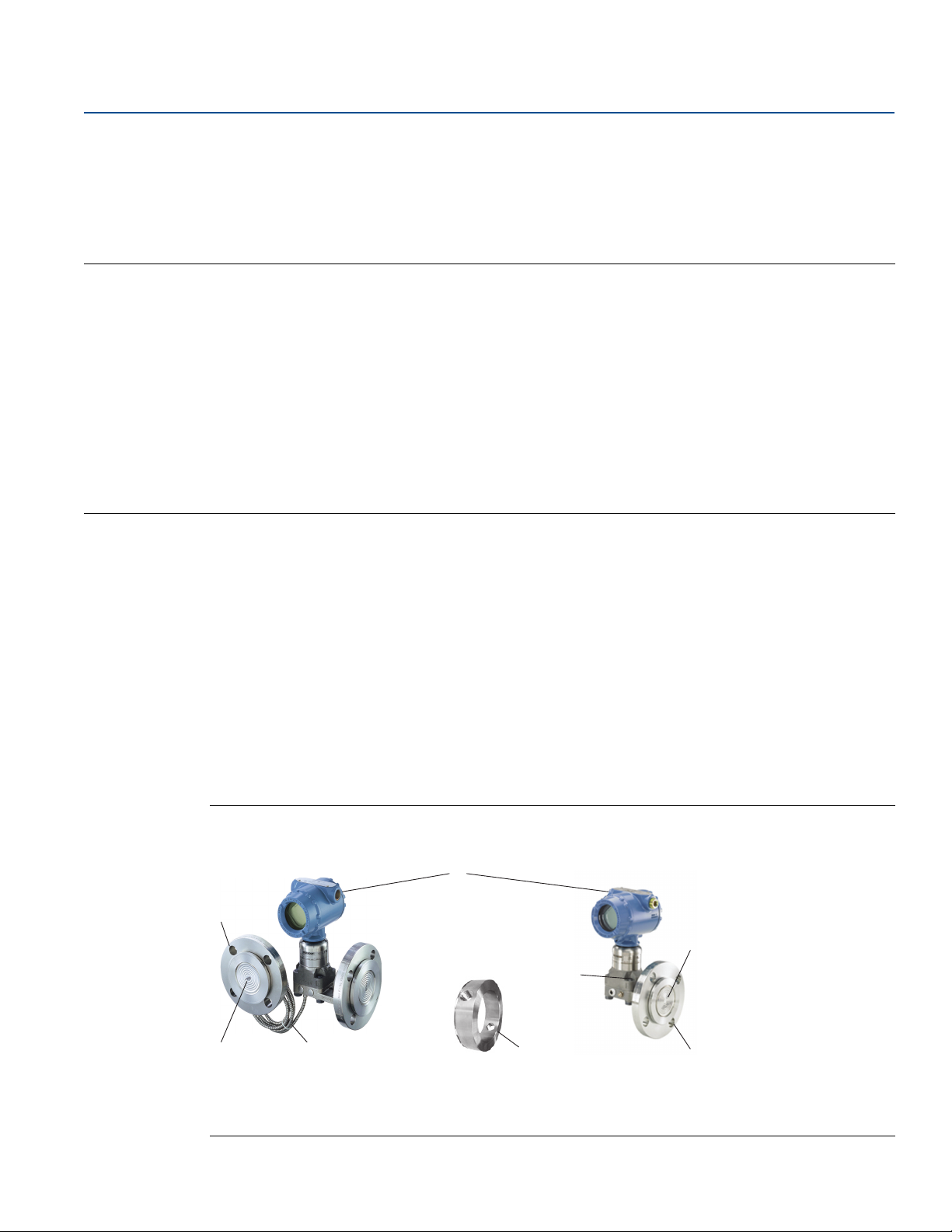
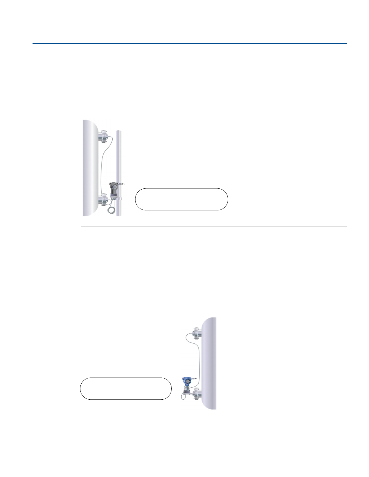
Figure 2-1 lists the basic components for seal assemblies.
Figure 2-1. Components on a Two and Single Seal Assembly
Two seal assembly Single seal assembly
Understanding Remote Seal Systems
A. Pressure, differential pressure, or multivariable transmitter
B. Process flange
C. Remote diaphragm
D. Capillary
E. Flushing connection
F. D ir ec t mou nt
3
Page 16
Understanding Remote Seal Systems
A
B
C
D
May 2017
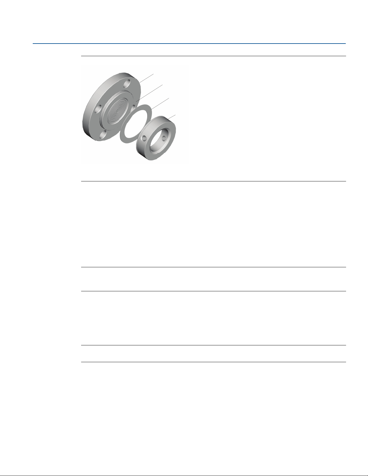
Figure 2-2. FFW Seal and Components
Reference Manual
00809-0100-4002, Rev DA
A. Process flange
B. Diaphragm
C. Gasket
D. Flushing connection
2.3 Understanding seal system performance
2.3.1 Volume temperature effects (process temperature effects)
Fill fluids expand or contract with temperature changes, creating a volume change that is absorbed by
the diaphragm seal and is seen as back pressure at the transmitter. This back pressure creates a shift in
the transmitter reading. For symmetrical or balanced systems, this error is usually minimal due to the
back pressure being equal on both sides. However, head temperature effect is still present.
Note
Other factors that affect seal temperature effect include diaphragm thickness, seal type and size,
capillary length and inner diameter.
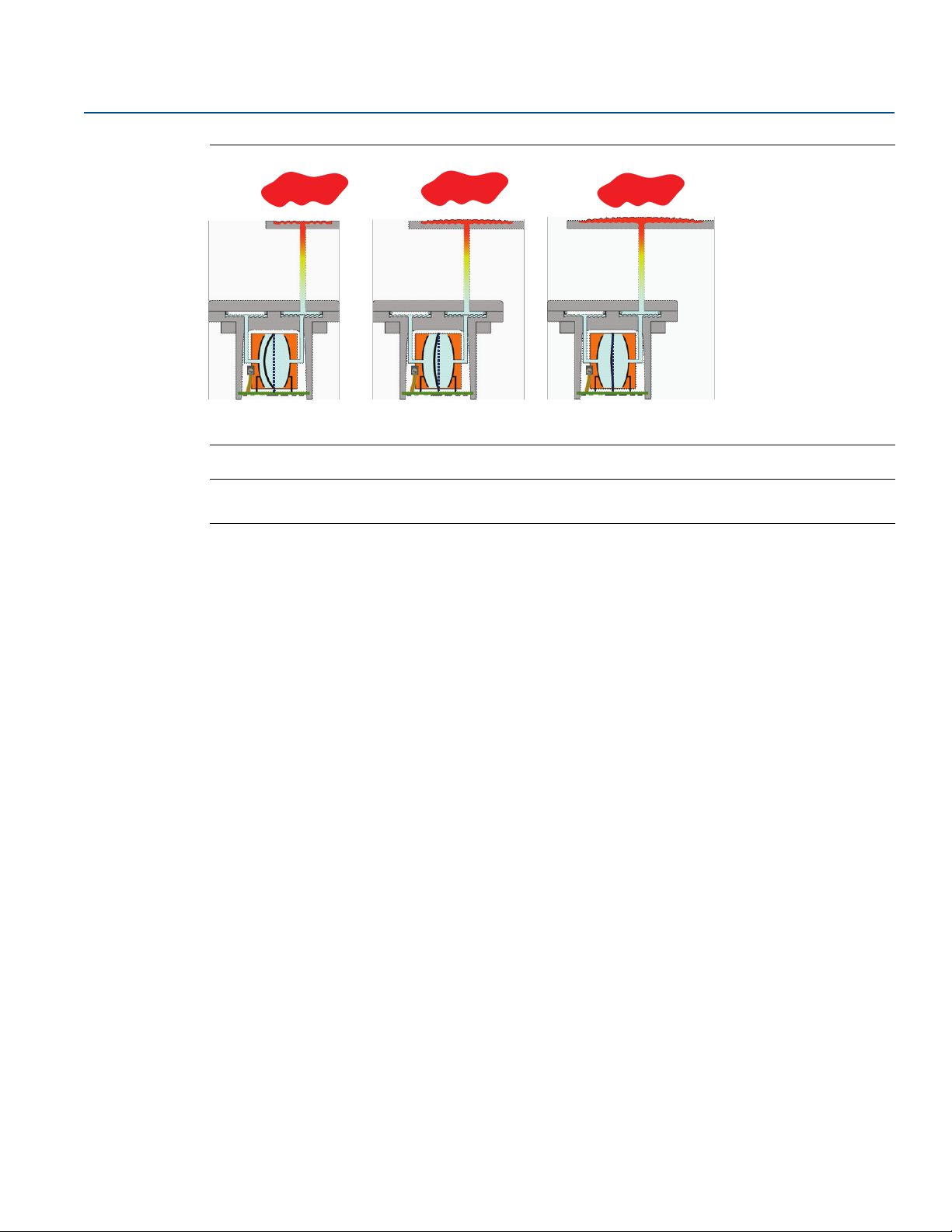
Figure 2-3 on page 5 shows how diaphragm size can affect the measurement reading at the transmitter.
For smaller seal sizes, such as the 1
additional 12.1 inH
has 0.5 inH
stable reading.
O error. Using a larger diaphragm can drastically improve performance and provides a more
2
O error. Moving to the 2-in. size gives 1.7 inH2O and the largest 3-in. size shown only
2
1
/2-in. size, the amount of back pressure on the transmitter causes an
Note
Calculations done in Instrument Toolkit™ with Silicone 200 fill fluid with Rosemount™ 3051 Transmitter.
4
Understanding Remote Seal Systems
Page 17
Reference Manual
00809-0100-4002, Rev DA
Figure 2-3. Back Pressure on Diaphragm Causing Error
Understanding Remote Seal Systems
May 2017
1½-in.
diapraghm
12.1 inH2O
(307 mmH
HEAT
O)
2
diapraghm
(43 mmH
2-in.
1.7 inH2O
HEAT
O)
2
3-in.
diapraghm
0.5 inH2O
(13 mmH
HEAT
O)
2
Note
Diaphragm temperature effects decrease as seal size increases.
2.3.2 Density temperature effects (head temperature effects)
Density temperature effect is due to the change in specific gravity of the fill fluid caused by a change in
ambient temperature. When installed, the weight of the fill fluid will produce an initial pressure read by
the transmitter, equaling the height between the high and low connection taps multiplied by the fill
fluid's specific gravity. As ambient temperature changes, the fill fluid specific gravity will change causing
the weight of the fill fluid to change, thus changing the pressure read by the transmitter. Density effect
will be seen in both
Tu ne d- S ys te m
transmitter regardless of where the transmitter is mounted.
™
Assemblies and Balanced System Assemblies and will have the same impact on the
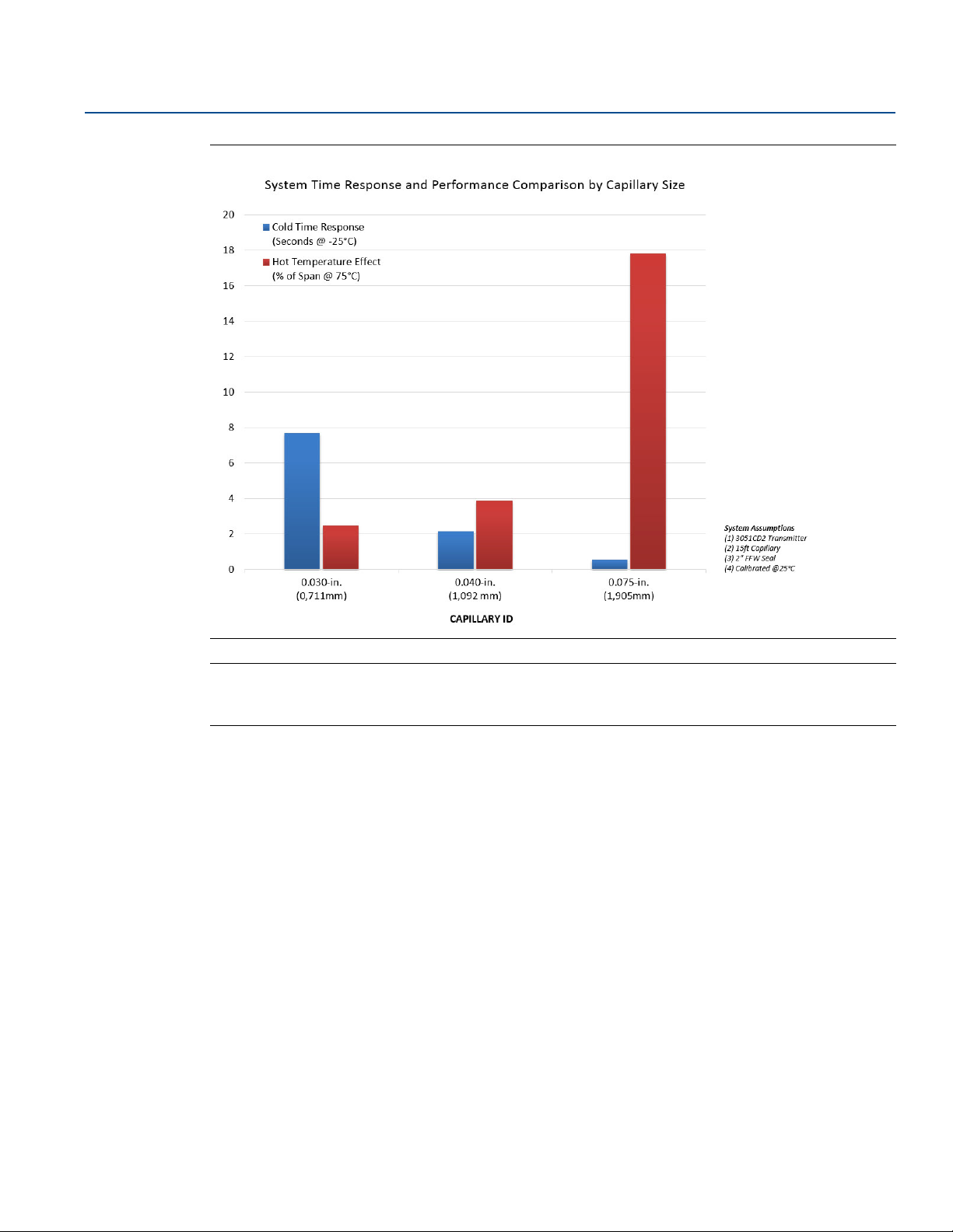
2.3.3 System time response and performance
The time response of a system is based on the type of transmitter, its sensor range, the length and inner
diameter (ID) of the capillary, and the viscosity of the fill fluid (which is directly affected by the process
and ambient temperatures). These factors all play a role in the overall performance of any seal system.
The relationship between system time response and temperature error is illustrated in Figure 2-4. It can
be seen that changing the capillary ID has an inverse affect between the time response and temperature
effect of a capillary system. As the capillary ID is increased, the time response of the system decreases
while the temperature effect increases.
Understanding Remote Seal Systems
5
Page 18
Understanding Remote Seal Systems
May 2017
Figure 2-4. Response Time vs. Total Performance Example
Reference Manual
00809-0100-4002, Rev DA
Note
Calculations conducted using Instrument Toolkit. Parameters: Silicone 200 fill fluid, Rosemount
3051CD2 Transmitter, 15 ft. capillary length, 2-in. FFW Seal, and calibrated at 25 °C.
6
Understanding Remote Seal Systems
Page 19
Reference Manual
Understanding Remote Seal Systems
00809-0100-4002, Rev DA
2.4 Balanced vs. Tuned-System assemblies
A balanced remote seal system is a symmetrical system that utilizes equal seals and capillary length on
the high and low pressure sides of the transmitter. Since the capillary lengths are the same, each side
ideally has the same amount of fill fluid, minimizing or completely eliminating the seal temperature
effect due to equal pressure on both sides of the transmitter diaphragm. The balanced systems are still
affected by the head pressure as shown in Figure 2-5.
Figure 2-5. Balanced System
May 2017
+3.6 inH2O
(9.0 mbar)
No error Seal temperature effect
(Cancels out)
+3.6 inH2O
(9.0 mbar)
Head temperature effect
Total temperature effect
on system
Note
Temperature effects were calculated in Instrument Toolkit using a 2-in. (DN 50) FFW seal, Silicone 200,
10 ft. (3 m) between the taps, over a 50 °F (28 °C) temperature change.
Tuned-Systems assemblies are asymmetrical remote seal systems with one seal directly mounted to the
high side of the differential pressure transmitter, and the other side connected to a seal via capillary.
Another possible Tuned-System assembly is any remote seal system with unequal lengths of capillary or
two different remote seals on the high and low pressure connections. Due to the unequal lengths of
capillary, there are seal temperature effects. However, this seal temperature effect counters the head
pressure from the oil-filled capillary and reduces total temperature effects on the entire system.
Figure 2-6. Tuned-System Assembly
Head temperature effect
Seal temperature effect
Total temperature effect
on system
Understanding Remote Seal Systems
+3.6 inH2O
(9.0 mbar)
-1.7 inH2O
(4.2 mbar)
+1.9 inH2O
(4.7 mbar)
7
Page 20

Understanding Remote Seal Systems
May 2017
Note
Temperature effects were calculated in Instrument Toolkit using a 2-in. (DN 50) FFW seal, Silicone 200,
10 ft. (3 m) between the taps, over a 50 °F (28 °C) temperature change.
Reference Manual
00809-0100-4002, Rev DA
2.5 Specifying the right solution for vacuum applications
2.5.1 Vacuum application overview
When a vessel is operating in a vacuum (negative gauge pressure), it is important to specify the correct
transmitter remote seal system to measure level accurately and reliably. Failure to do so can result in
output drift or complete system failure. The combination of high process temperature and vacuum
process pressure conditions creates additional requirements when specifying the transmitter remote
seal system.
2.5.2 Vacuum applications
There are three primary transmitter-seal system components necessary to successfully specify vacuum
application solutions:
Seal system construction
Fill fluid selection
Transmitter mounting position
2.5.3 Seal system construction for vacuum applications
Emerson™ offers welded-repairable or all-welded vacuum system construction styles on diaphragm seal
assembles.
The all-welded vacuum construction was designed specifically for vacuum applications. In this
construction, the sensor module gaskets are removed and a disk is welded over the sensor isolators. This
eliminates the possibility of air being drawn into the seal system in deep vacuum conditions. This
premium design is strongly suggested for vacuum pressures below 6 psia (310 mmHga).
2.5.4 Transmitter mounting position
Mounting the pressure transmitter at or below the bottom vessel tap is an important factor to ensure a
stable measurement with vacuum applications. The static pressure limit for a differential pressure
transmitter is 0.5 psia (25 mmHgA), which ensures the transmitter sensor module fill fluid remains
within the liquid phase of the vapor pressure curve.
If the vessel static limit is below 0.5 psia, mounting the transmitter below the bottom tap provides a
capillary fill fluid head pressure on the module. A general rule is to always mount the transmitter
approximately 3 ft. (1 m) below the bottom tap of the vessel.
2.5.5 Fill fluid selection
When the process is under vacuum conditions, the fill fluid can vaporize at a lower temperature than
when it is under normal atmospheric or greater pressure. Each fill fluid has a specific vapor-pressure
curve. The vapor-pressure curve indicates the pressure and temperature relationship where the fluid is in
a liquid or a vapor state. Proper seal operation requires the fill fluid to remain in a liquid state.
8
Understanding Remote Seal Systems
Page 21
Reference Manual
A
BD
C
EF
A
B
C
D
E
00809-0100-4002, Rev DA
For vacuum applications, specify fluids that are specifically designed for use in these types of
applications such as Silicone 704 for vacuum applications, Silicone 705 for vacuum applications, or
UltraTherm
™
805 for vacuum applications. These fluids have been specially processed to deliver the
maximum vapor pressure curve performance possible. For more information on Rosemount Diaphragm
Seal fill fluids, reference the Rosemount 1199 Fill Fluid Specifications Tec hnical Note
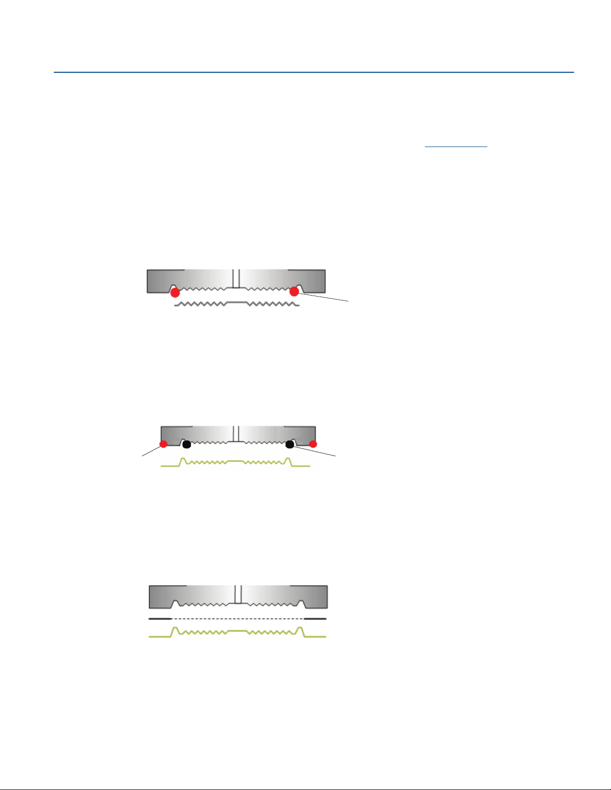
2.6 Diaphragm weld types
Weld-type is factory-determined as best for the seal typed specified. PFW and FFW seals have ordering
options that specify welding options.
2.6.1 Solid faceplate design
The solid faceplate design is used when diaphragm and upper housing material are the same.
AB
AC
A. Material A
B. Upper housing
C. Diaphragm
D. TIG weld point
Understanding Remote Seal Systems
May 2017
.
D
2.6.2 Seam weld design
A seam weld design is used when the upper housing material is different from the diaphragm material.
The seam welded design has a hermetic weld at the inner diameter of the diaphragm and a TIG weld at
the outer edge. The diaphragm floats on the upper housing over the gasket surface area and could tear if
a metallic gasket were used.
A. Material A
B. Material B
C. Upper housing
2.6.3 Brazed design
This process uses a brazing ring where the metals are brazed to attach the diaphragm to the upper
housing. This allows the gasket surface area to solidify as it is melted to the upper housing.
This option is used with Tantalum diaphragm when a metallic gasket is required.
D. Diaphragm
E. TIG weld point
F. Se am wel d p oi nt
A. Material A
B. Tantalum
C. Upper housing
Understanding Remote Seal Systems
D. Brazing ring
E. Diaphragm
9
Page 22
Understanding Remote Seal Systems
A
B
May 2017
Reference Manual
00809-0100-4002, Rev DA
2.7 Differences between electronic remote sensors and capillary systems
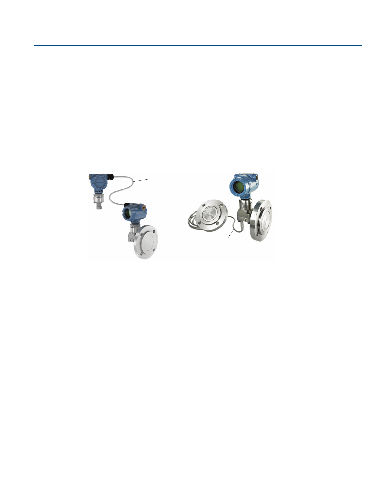
Rosemount 3051S Electronic Remote Sensors (ERS™) System technology utilizes two Rosemount 3051S
Pressure Transmitters connected via an electrical wire instead of a single pressure transmitter with
remote seals and capillary tubing. As the Rosemount 3051S ERS System calculates the differential
pressure between the two transmitters, capillary tubing is not needed, and thus eliminates all head
temperature affects on the system. Seals are not required, but may still be necessary on certain
applications that include high temperature, corrosive, or viscous processes. For more information, refer
to the Rosemount 3051S Series Product Data Sheet
Figure 2-7. ERS vs. Capillary
Rosemount 3051S ERS Traditional capillary system
.
A. Non-proprietary electrical cable
B. Oil-filled capillary system
2.8 Instrument Toolkit: seal ordering and application process
Rosemount Instrument Toolkit Software is an instrumentation specification tool that can be used to
assist in product selection. This program analyzes application and process conditions against a
configured Rosemount model number and calculates the total system performance including expected
head and seal temperature effects and system response times.
Visit the Emerson website for information on how to obtain and use Instrument Toolkit.
10
Understanding Remote Seal Systems
Page 23

Reference Manual
00809-0100-4002, Rev DA
Understanding Remote Seal Systems
May 2017
2.9 Rosemount Thermal Range Expander: proper use and applications
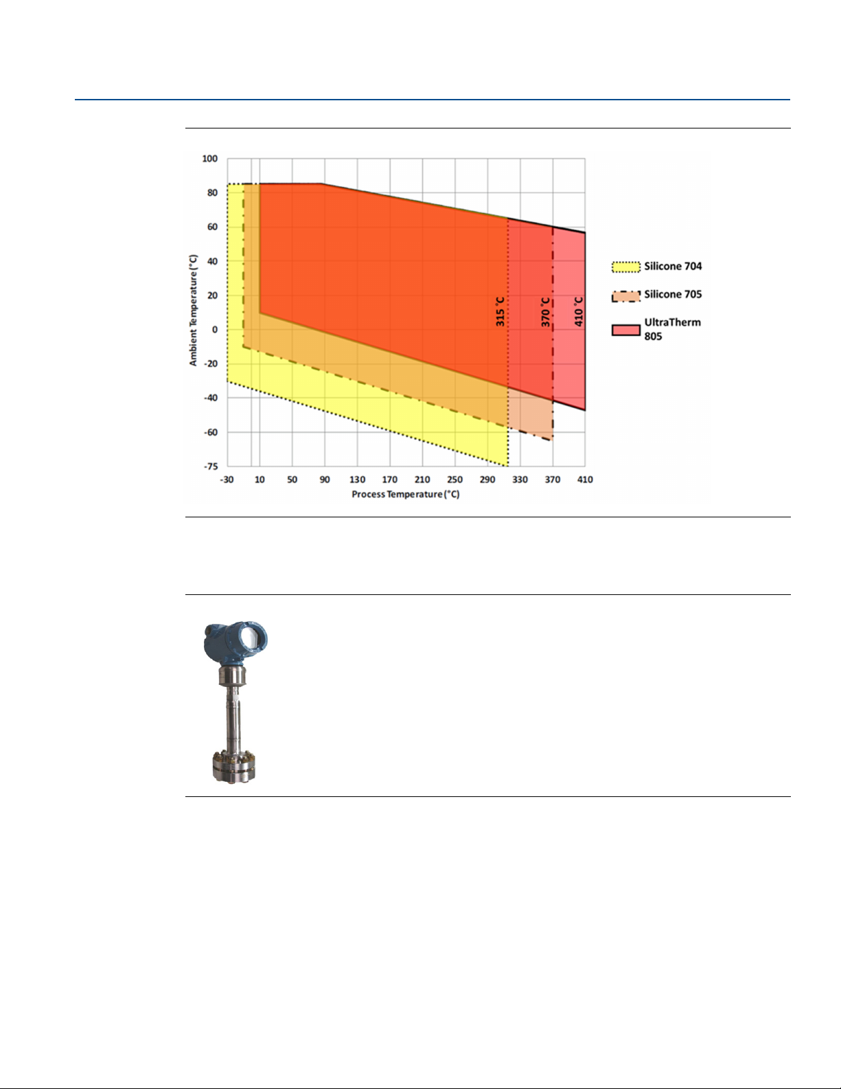
Figure 2-8. Rosemount Thermal Range Expander
The Rosemount Thermal Range Expander increases the application range where DP Level technology can
be used by expanding the ambient and process temperature ranges of the system.
Traditional remote seal systems are filled with a single fill fluid to operate in applications with varying
ambient and process conditions. Silicone 704 and 705 are commonly used fluids for hot process
applications going above 570 °F (300 °C); these fluids must be kept above 32 °F (0 °C) and 68 °F (20 °C),
respectively, in order to properly transmit the pressure signal to the transmitter. This can prove to be
difficult for outdoor installations where extremely cold ambient conditions cause these fill fluids to gel.
The Rosemount Thermal Range Expander is a seal system that uses two different fill fluids to extend the
operating temperature range of the system. A high temperature fill fluid, which is next to the hot
process, is kept warm enough to stay responsive. A second fill fluid, located on the other side of the
intermediate diaphragm, operates over a wide ambient temperature range. The Rosemount Thermal
Range Expander can operate in ambient temperatures as low as –75 °C (–103 °F), and process
temperatures up to 410 °C (770 °F). This improves response time up to 46 percent and eliminates the
need for mechanical heat tracing.
The Rosemount Thermal Range Expander can be used with any Rosemount 3051S DP Level configuration
including Balanced Systems, Tuned-System Assembles, Electronic Remote Sensors (ERS), or direct
mounted to a transmitter.
Figure 2-9. Rosemount Thermal Range Expander Fill Fluids
A. Intermediate diaphragm
B. High temperature fill fluid (viscous)
C. Ambient temperature fill fluid
Understanding Remote Seal Systems
11
Page 24
Understanding Remote Seal Systems
May 2017
Figure 2-10. Rosemount Thermal Range Expander Temperature Operating Range
Reference Manual
00809-0100-4002, Rev DA
2.10 Thermal optimizer: proper use and applications
Figure 2-11. Thermal Optimizer
The thermal optimizer keeps fill fluids from gelling in cold ambient temperatures by using high process
temperatures to heat the transmitter and capillary.
High temperature silicone fill fluid has a low temperature limit in ambient conditions below 32 °F (0 °C).
The thermal optimizer allows direct mounting down to –94 °F (–70 °C).
12
Understanding Remote Seal Systems
Page 25
Reference Manual
212 °F (100 °C)
176 °F (80°C)
140 °F (60 °C)
104 °F (40 °C)
68 °F (20 °C)
32 °F (0 °C)
-4 °F (-20 °C)
-40 °F (-40 °C)
-76 °F (-60 °C)
-112 °F (-80 °C)
212 °F (100 °C)
176 °F (80°C)
140 °F (60 °C)
104 °F (40 °C)
68 °F (20 °C)
32 °F (0 °C)
-4 °F (-20 °C)
-40 °F (-40 °C)
-76 °F (-60 °C)
-112 °F (-80 °C)
32 °F (0 °C)
122 °F (50 °C)
302 °F (150 °C)
482 °F (250 °C)
622 °F (350 °C)
842 °F (450 °C)
401 °F (205 °C)
185 °F (85 °C)
185 °F (85 °C)
599 °F (315 °C)
-58 °F (-50 °C)
91 °F (33 °C)
Process temperature °F (°C)
Ambient temperature °F (°C)
Ambient temperature °F (°C)
Process temperature °F (°C)
122 °F (50 °C)
302 °F (150 °C)
482 °F (250 °C)
622 °F (350 °C)
842 °F (450 °C)
185 °F (85 °C)
185 °F (85 °C)
-58 °F (-50 °C)
401 °F (205 °C)
-69 °F (-56 °C)
-76 °F (-60 °C)
68 °F (20 °C)
662 °F (350 °C)
68 °F (20 °C)
68 °F (20 °C)
698 °F (370 °C)
77 °F (25 °C)
00809-0100-4002, Rev DA
Figure 2-12. Fill Fluid Temperature Limits
Thermal optimizer with Silicone 704 Thermal optimizer with Silicone 705
Understanding Remote Seal Systems
May 2017
2.10.1 Thermal optimizer limitations
2.11 Submersible seal
2.11.1 Designed for top-down measurement
Understanding Remote Seal Systems
Figure 2-12 shows the process and ambient temperature limits for the thermal optimizer with Silicone
704 and Silicone 705 Fill Fluids respectively. The shaded areas represent the temperature limitations;
applications outside of the shaded area cannot be used with a thermal optimizer.
For example, an application with an ambient temperature of 50 °F (10 °C) and a process temperature of
300 °F (149 °C) is within the limits, a thermal optimizer can be used in this application.
However, an application with an ambient temperature of 120 °F (40 °C) and a process temperature of
464 °F (240 °C) is outside of the limits. These high temperatures would be detrimental to the transmitter
electronics.
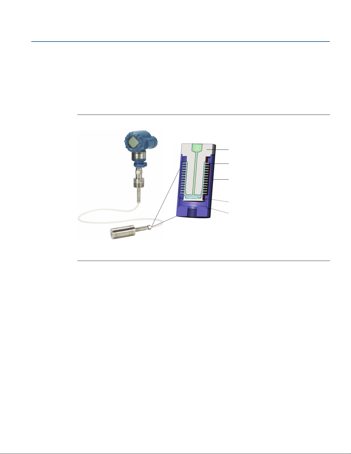
The submersible seal consists of a bellows-style seal and is designed for measuring level in top-down
applications with small tank connections, specifically 1.5-in. NPT threaded connections or 2- to 4-in.
flanges. For tanks with larger connections or open process measurements, an RTW seal should be
specified as it will provide a more accurate measurement.
Apart from traditional DP Level transmitters, this new design has both the seal and capillary submersed
in the process as shown below. Traditional DP Level seal systems are side mounted to tanks such that the
diaphragm seal is the only wetted material that comes in direct contact with the process fluid.
This assembly can only be ordered with Rosemount in-line transmitters for gage measurements.
Differential and absolute measurements are not available.
13
Page 26
Understanding Remote Seal Systems
A
B
C
D
E
May 2017
2.11.2 Submersible Seal features
Specifically designed for top-down process measurements
Bellows-style seal absorbs pressures efficiently for smaller process connections
Threaded or flanged process connections
Uses proven and reliable DP Level remote seals
Up to 30 ft. (9,1m) of capillary
Figure 2-13. Rosemount Submersible Seal attached to a Rosemount 3051T Wireless Pressure
Tra ns mit te r
Reference Manual
00809-0100-4002, Rev DA
A. Seal body
B. Bellows
C. Outer tube
D. Fill fluid
E. Process fluid
14
Understanding Remote Seal Systems
Page 27

Reference Manual
00809-0100-4002, Rev DA
Section 3 Installation
Seals handling and installation . . . . . . . . . . . . . . . . . . . . . . . . . . . . . . . . . . . . . . . . . . . . . . . . . . . . . . . . . page 15
Gaskets . . . . . . . . . . . . . . . . . . . . . . . . . . . . . . . . . . . . . . . . . . . . . . . . . . . . . . . . . . . . . . . . . . . . . . . . . . . . . . page 17
Tagging . . . . . . . . . . . . . . . . . . . . . . . . . . . . . . . . . . . . . . . . . . . . . . . . . . . . . . . . . . . . . . . . . . . . . . . . . . . . . page 18
Max working pressure . . . . . . . . . . . . . . . . . . . . . . . . . . . . . . . . . . . . . . . . . . . . . . . . . . . . . . . . . . . . . . . . .page 18
FFW flush flanged seal . . . . . . . . . . . . . . . . . . . . . . . . . . . . . . . . . . . . . . . . . . . . . . . . . . . . . . . . . . . . . . . . . page 19
RFW off-line flanged seal . . . . . . . . . . . . . . . . . . . . . . . . . . . . . . . . . . . . . . . . . . . . . . . . . . . . . . . . . . . . . . page 29
EFW extended flanged seal . . . . . . . . . . . . . . . . . . . . . . . . . . . . . . . . . . . . . . . . . . . . . . . . . . . . . . . . . . . . page 33
PFW pancake seal . . . . . . . . . . . . . . . . . . . . . . . . . . . . . . . . . . . . . . . . . . . . . . . . . . . . . . . . . . . . . . . . . . . . . page 42
FCW flush flanged seal—ring type joint (RTJ) gasket surface . . . . . . . . . . . . . . . . . . . . . . . . . . . . . . . .page 45
RCW off-line ring type joint (RTJ) flanged seal . . . . . . . . . . . . . . . . . . . . . . . . . . . . . . . . . . . . . . . . . . . . page 48
FUW flush flanged groove type seals . . . . . . . . . . . . . . . . . . . . . . . . . . . . . . . . . . . . . . . . . . . . . . . . . . . . page 50
FVW flush flanged tongue type seals . . . . . . . . . . . . . . . . . . . . . . . . . . . . . . . . . . . . . . . . . . . . . . . . . . . . page 51
RTW off-line threaded type seals . . . . . . . . . . . . . . . . . . . . . . . . . . . . . . . . . . . . . . . . . . . . . . . . . . . . . . . page 53
HTS male threaded seal . . . . . . . . . . . . . . . . . . . . . . . . . . . . . . . . . . . . . . . . . . . . . . . . . . . . . . . . . . . . . . . . page 55
SCW hygienic Tri-Clover Tri Clamp seals . . . . . . . . . . . . . . . . . . . . . . . . . . . . . . . . . . . . . . . . . . . . . . . . . . page 56
SSW hygienic tank spud seal . . . . . . . . . . . . . . . . . . . . . . . . . . . . . . . . . . . . . . . . . . . . . . . . . . . . . . . . . . . page 58
STW hygienic thin wall tank spud seal . . . . . . . . . . . . . . . . . . . . . . . . . . . . . . . . . . . . . . . . . . . . . . . . . . . page 61
EES hygienic flanged tank spud extended seal . . . . . . . . . . . . . . . . . . . . . . . . . . . . . . . . . . . . . . . . . . . . page 62
VCS Tri Clamp In-line seal . . . . . . . . . . . . . . . . . . . . . . . . . . . . . . . . . . . . . . . . . . . . . . . . . . . . . . . . . . . . . . page 63
SVS VARIVENT compatible hygienic connection seal . . . . . . . . . . . . . . . . . . . . . . . . . . . . . . . . . . . . . . page 64
SHP hygienic Cherry-Burrell “I” line seal . . . . . . . . . . . . . . . . . . . . . . . . . . . . . . . . . . . . . . . . . . . . . . . . . . page 65
SLS dairy process connection–female thread seal per DIN 11851 . . . . . . . . . . . . . . . . . . . . . . . . . . . page 66
WSP saddle seal . . . . . . . . . . . . . . . . . . . . . . . . . . . . . . . . . . . . . . . . . . . . . . . . . . . . . . . . . . . . . . . . . . . . . . page 67
UCP union connection pipe mount seal . . . . . . . . . . . . . . . . . . . . . . . . . . . . . . . . . . . . . . . . . . . . . . . . . . page 69
PMW paper mill sleeve seal . . . . . . . . . . . . . . . . . . . . . . . . . . . . . . . . . . . . . . . . . . . . . . . . . . . . . . . . . . . . page 71
CTW chemical tee seal . . . . . . . . . . . . . . . . . . . . . . . . . . . . . . . . . . . . . . . . . . . . . . . . . . . . . . . . . . . . . . . . page 73
TFS wafer style In-line seal . . . . . . . . . . . . . . . . . . . . . . . . . . . . . . . . . . . . . . . . . . . . . . . . . . . . . . . . . . . . . page 74
WFW flow-thru flanged seal . . . . . . . . . . . . . . . . . . . . . . . . . . . . . . . . . . . . . . . . . . . . . . . . . . . . . . . . . . . . page 75
Installation
May 2017
Additional specialized remote seals are available. Contact Emerson
information on these seals.
3.1 Seals handling and installation
3.1.1 Diaphragm
The remote seal diaphragm is designed to withstand pressure and wear from process, but outside of
process connection conditions, remote seals are delicate and should be handled with care.
The protective cover should remain on the seal until the moment before installation. Try to avoid
touching the diaphragm with fingers or objects and refrain from setting the diaphragm side of the seal
down on a hard surface.
Installation
™
Technical Support for installation
15
Page 28
Installation
May 2017
Even minor dents or scratches in the diaphragm material may impair the performance of the seal system
assembly. Care should be taken to ensure the seal diaphragm is not dented or damaged during seal
installation.
3.1.2 Capillary
When unpacking or handling seal system assemblies, do not lift the seal or transmitter by gripping the
capillaries. Avoid sharply bending or crimping the capillary tubing. The minimum bending radius of the
capillary tubing is 3-in. (8 cm).
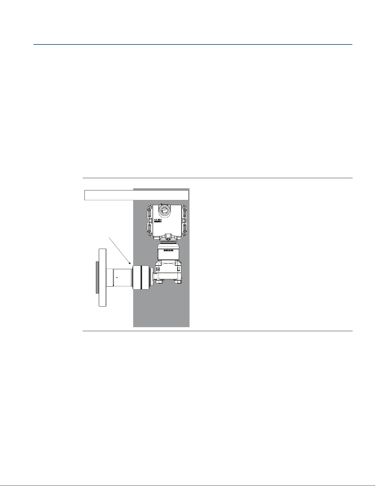
3.1.3 Rosemount Thermal Range Expander
The Rosemount™ Thermal Range Expander system uses the heat from the process in order to keep both
fluids within the system functioning properly; therefore insulation is not always required. However, it is
always best practice to insulate systems to keep them functioning with optimum performance. The
Rosemount Thermal Range Expander should never be insulated above the line marked on the seal itself.
Figure 3-1. Rosemount 3051SAL with Rosemount Thermal Range Expander Insulation Guidelines
Rosemount 3051SAL with Thermal Range Expander
Reference Manual
00809-0100-4002, Rev DA
Marking:
“Do Not Insulate
Above this Line”
Ok to
Insulate
3.1.4 Heat tracing
When using heat or steam tracing, exercise caution if PVC coating is added onto capillary, as PVC coating
should not be exposed to temperatures above 212 °F (100 °C) to avoid the possibility of thermal
breakdown.
Best practice for heat and steam tracing is to regulate the temperature slightly above the maximum
ambient temperature for a consistent result. To avoid accuracy effects and thermal stress, the capillary
should not be partially heated.
Do Not
Insulate
16
Installation
Page 29

Reference Manual
00809-0100-4002, Rev DA
NEVER attempt to disconnect the seals or capillaries from the transmitter or loosen bolts. Doing so will
result in loss of fill fluid and will void the product warranty.
Failing to recognize incorrect materials during installation may cause process leaks, which can result in
damage to the diaphragm seal system or death and/or serious injury to personnel. Proper wetted
material is required for specific process materials.
3.2 Gaskets
When installing remote seal systems which employ a gasket or a gasket and flushing connection ring,
make sure the gasket is aligned properly on the gasket sealing surface.
The user is responsible to ensure the gasket used does not exceed the temperature limits of the process.
Failure to properly install the gasket may cause process leaks, which can result in death or serious injury.
In addition, make sure the gasket does not press down upon the diaphragm face. Anything pressing on
the diaphragm will be read by the transmitter as pressure. A misaligned gasket may cause a false reading.
Installation
May 2017
The intermediate gasket between the seal and lower housing is supplied when the lower housing or
flushing connection is provided. The default gaskets are listed in Tab l e 3 -1 based on seal type. The
process gasket must be supplied by the end user. Tantalum diaphragms are not supplied with default
gasket, so a gasket option must be selected when applicable.
If a lower housing is supplied, then the following gaskets are the default gaskets for each seal unless
another gasket option is selected.
Table 3-1. Gaskets Materials
Seal type Gaskets
Flanged seals assemblies
FFW Thermo-Tork® TN-9000
RFW Klinger C-4401
EFW No gasket is supplied
PFW Thermo-Tork TN-9000
FCW No gasket is supplied
RCW Klinger C-4401
FUW/FVW No gasket is supplied
Threaded seal assemblies
RTW Klinger C-4401
HTS No gasket is supplied
Hygienic seal assemblies
(1)
SCW
SSW Ethylene propylene O-ring
STW Ethylene propylene O-ring
EES No gasket is supplied
(1)
VCS
(1)
SVS
SHP No gasket is supplied
(1)
SLS
(1)
MLS
No gasket is supplied
No gasket is supplied
No gasket is supplied
No gasket is supplied
No gasket is supplied
Installation
17
Page 30
Installation
May 2017
Table 3-1. Gaskets Materials
Specialty seals
WSP Klinger C-4401
UCP Barium-Sulfate filled PTFE O-ring
CTW No gasket is supplied
TFW No gasket is supplied
WFW Klinger C-4401
1. Ensure to use EHEDG approved gasket for EHEDG conformity.
Note
The end-user is responsible for choosing a gasket and ensuring the process temperature does not exceed
the temperature limits of the gasket used. Failure to properly install the gasket may cause process leaks,
which can result in death or serious injury.
3.3 Tagging
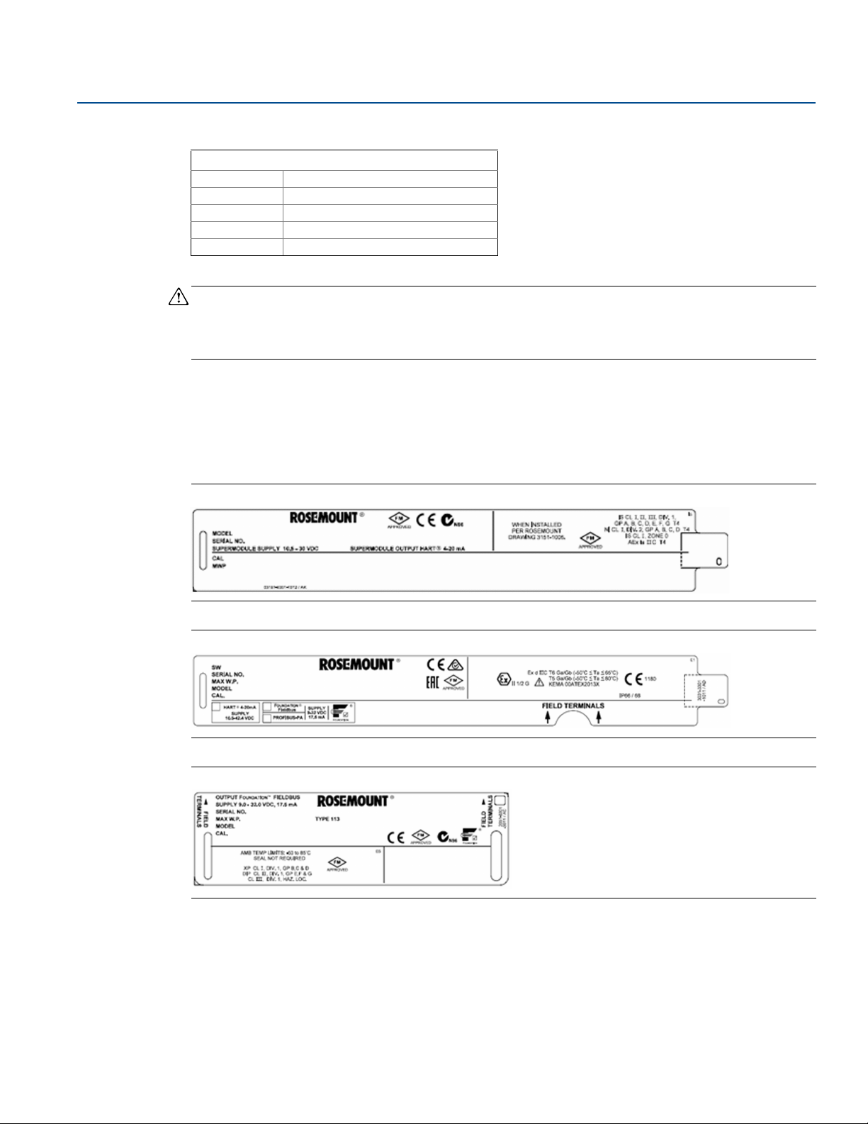
Each remote seal system is tagged in accordance with the end-user requirements.
The remote seal model number is identified on the transmitter label, shown in Figure 3-2, 3-3, and 3-4.
Reference Manual
00809-0100-4002, Rev DA
Figure 3-2. Rosemount 3051S Sample Label
Figure 3-3. Rosemount 3051 Sample Label
Figure 3-4. Rosemount 2051 Sample Label
3.3.1 Max working pressure
The maximum working pressure (MWP) of the seal system assembly is stamped on the transmitter neck
tag. This can be dependent upon the maximum pressure rating of the seal system or transmitter upper
range limit.
18
Installation
Page 31

Reference Manual
00809-0100-4002, Rev DA
3.4 FFW flush flanged seal
Figure 3-5. FFW Two-Piece Design (Shown with Flushing Ring)
P
E
H
I
Standard expanded
J
øA
øC
2.00 51
2.25 57
B
Installation
May 2017
øD
A–D. Refer to Tab l e 3 -2
E. Process flange
F–G. Refer to Tab l e 3 -2
H. Diaphragm
I. Flushing ring
J. Connection to transmitter
K–N. Refer to Tab le 3 -3
O. Flushing connection
P. Alignment clamp (option code SA)
M
øF
øN
øG
øK
øL
Dimensions are in inches (millimeters).
Note
For the two-piece design, the seal assembly and process flange are separate components and can be
rotated independent of each other. The Alignment clamp (P) can be ordered using option code SA.
Table 3-2. FFW Two-Piece (Upper Housing and Flange) Design Dimensions
Pipe
size
Class
Flange
diameter
“A”
in. (mm)
Flange
thickness
“B”
in. (mm)
Bolt
circle
“C”
in. (mm)
øG
Number
of bolts
Bolt hole
diameter
“D”
in. (mm)
.31 8
.50 13
H
O
Standard
diaphragm
diameter
in. (mm)
“F”
Raised
face outer
diameter
“G”
in. (mm)
ANSI/ASME
Installation
150 lb 6.00 (152) 0.69 (18) 4.75 (121) 4 0.75 (19) 2.30 (58) 3.62 (92)
300 lb 6.50 (165) 0.81 (21) 5.00 (127) 8 0.75 (19) 2.30 (58) 3.62 (92)
600 lb 6.50 (165) 1.00 (25) 5.00 (127) 8 0.75 (19) 2.30 (58) 3.62 (92)
2-in.
900 lb 8.50 (216) 1.50 (38) 6.50 (165) 8 1.00 (25) 2.30 (58) 3.62 (92)
1500 lb 8.50 (216) 1.50 (38) 6.50 (165) 8 1.00 (25) 2.30 (58) 3.62 (92)
2500 lb 9.25 (235) 2.00 (51) 6.75 (172) 8 1.13 (29) 2.30 (58) 3.62 (92)
19
Page 32

Installation
May 2017
Table 3-2. FFW Two-Piece (Upper Housing and Flange) Design Dimensions
Reference Manual
00809-0100-4002, Rev DA
ANSI/ASME
Pipe
size
3-in.
4-in.
DN 50
Flange
Class
diameter
“A”
in. (mm)
150 lb 7.50 (191) 0.88 (22) 6.00 (152) 4 0.75 (19) 3.50 (89) 5.00 (127)
300 lb 8.25 (210) 1.06 (27) 6.62 (168) 8 0.88 (22) 3.50 (89) 5.00 (127)
600 lb 8.25 (210) 1.25 (32) 6.62 (168) 8 0.88 (22) 3.50 (89) 5.00 (127)
900 lb 9.50 (241) 1.50 (38) 7.50 (191) 8 1.00 (25) 3.50 (89) 5.00 (127)
1500 lb 10.50 (267) 1.88 (48) 8.00 (203) 8 1.25 (32) 3.50 (89) 5.00 (127)
2500 lb 12.00 (305) 2.62 (67) 9.00 (229) 8 1.38 (35) 3.50 (89) 5.00 (127)
150 lb 9.00 (229) 0.88 (22) 7.50 (191) 8 0.75 (19) 3.50 (89) 6.20 (157)
300 lb 10.0 (254) 1.19 (30) 7.88 (200) 8 0.88 (22) 3.50 (89) 6.20 (157)
600 lb 10.75 (273) 1.50 (38) 8.50 (216) 8 1.00 (25) 3.50 (89) 6.20 (157)
900 lb 11.50 (292) 1.75 (45) 9.25 (235) 8 1.25 (32) 3.50 (89) 6.20 (157)
1500 lb 12.25 (311) 2.12 (54) 9.50 (241) 8 1.38 (35) 3.50 (89) 6.20 (157)
2500 lb 14.00 (356) 3.00 (76) 10.75(274) 8 1.63 (41) 3.50 (89) 6.20 (157)
PN 40 6.50 (165) 0.67 (17) 4.92 (125) 4 0.71 (18) 2.30 (58) 4.00 (102)
PN 63 7.09 (180) 0.91 (23) 5.31 (135) 4 0.87 (22) 2.30 (58) 4.00 (102)
PN 100 7.68 (195) 0.99 (25) 5.71 (145) 4 1.02 (26) 2.30 (58) 4.00 (102)
Flange
thickness
“B”
in. (mm)
Bolt
circle
“C”
in. (mm)
Number
of bolts
Bolt hole
diameter
“D”
in. (mm)
Standard
diaphragm
diameter
“F”
in. (mm)
Raised
face outer
diameter
“G”
in. (mm)
EN1092-1
DN 80
DN 100
PN 160 7.68 (195) 1.06 (27) 5.71 (145) 4 1.02 (26) 2.30 (58) 4.00 (102)
PN 40 7.87 (200) 0.83 (21) 6.30 (160) 8 0.71 (18) 3.50 (89) 5.43 (138)
PN 63 8.46 (215) 0.99 (25) 6.69 (170) 8 0.88 (22) 3.50 (89) 5.43 (138)
PN 100 9.06 (230) 1.15 (29) 7.09 (180) 8 1.02 (26) 3.50 (89) 5.43 (138)
PN 160 9.06 (230) 1.30 (33) 7.09 (180) 8 1.02 (26) 3.50 (89) 5.43 (138)
PN 10/16 8.66 (220) 0.67 (17) 7.09 (180) 8 0.71 (18) 3.50 (89) 6.20 (157)
PN 40 9.25 (235) 0.94 (24) 7.48 (190) 8 0.87 (22) 3.50 (89) 6.20 (157)
PN 63 9.84 (250) 0.83 (21) 7.87 (200) 8 1.02 (26) 3.50 (89) 6.20 (157)
PN 100 10.43 (265) 1.30 (27) 8.27 (210) 8 1.18 (30) 3.50 (89) 6.20 (157)
PN 160 10.43 (265) 1.46 (37) 8.27 (210) 8 1.18 (30) 3.50 (89) 6.20 (157)
20
Installation
Page 33

Reference Manual
00809-0100-4002, Rev DA
Table 3-2. FFW Two-Piece (Upper Housing and Flange) Design Dimensions
Installation
May 2017
Flange
Pipe
size
Class
diameter
“A”
in. (mm)
10K 6.10 (155) 0.63 (16) 4.72 (120) 4 0.75 (19) 2.30 (58) 3.62 (92)
50A
80A
JIS
100A
20K 6.10 (155) 0.71 (18) 4.72 (120) 8 0.75 (19) 2.30 (58) 3.62 (92)
40K 6.50 (165) 1.02 (26) 5.12 (130) 8 0.75 (19) 2.30 (58) 4.00 (102)
10K 7.28 (185) 0.71 (18) 5.91 (150) 8 0.75 (19) 3.50 (89) 5.00 (127)
20K 7.87 (200) 0.87 (22) 6.30 (160) 8 0.91 (23) 3.50 (89) 5.00 (127)
40K 8.27 (210) 1.26 (32) 6.69 (170) 8 0.91 (23) 3.50 (89) 5.43 (138)
10K 8.27 (210) 0.71 (18) 6.89 (175) 8 0.75 (19) 3.50 (89) 6.20 (157)
20K 8.86 (225) 0.95 (24) 7.28 (185) 8 0.91 (23) 3.50 (89) 6.20 (157)
40K 9.84 (250) 1.42 (36) 8.07 (205) 8 0.98 (25) 3.50 (89) 6.20 (157)
Flange
thickness
“B”
in. (mm)
Table 3-3. FFW Flush Connection Ring Dimensions
Pipe
size
Class
Inner
diameter
“K”
in. (mm)
Beveled
edge
“L”
in. (mm)
Bolt
circle
“C”
in. (mm)
Thickness “M”
1/4-in. NPT
flush
connection
Number
of bolts
in. (mm)
connection
Bolt hole
diameter
in. (mm)
1
/2-in. NPT
flush
“D”
Standard
diaphragm
diameter
“F”
in. (mm)
Minimum
gasket I.D.
“N”
in. (mm)
Raised
face outer
diameter
“G”
in. (mm)
Weight
lb (kg)
ANSI/ASME
150 lb 2.12 (54) 2.48 (63) 0.97 (25) 1.30 (33) 2.50 (64) 7.40 (3,33)
300 lb 2.12 (54) 2.48 (63) 0.97 (25) 1.30 (33) 2.50 (64) 8.99 (4,05)
600 lb 2.12 (54) 2.48 (63) 0.97 (25) 1.30 (33) 2.50 (64) 10.44 (4,70)
2-in.
900 lb 2.12 (54) 2.48 (63) 0.97 (25) 1.30 (33) 2.50 (64) 24.62 (11,08)
1500 lb 2.12 (54) 2.48 (63) 0.97 (25) 1.30 (33) 2.50 (64) 24.62 (11,08)
2500 lb 2.12 (54) 2.48 (63) 0.97 (25) 1.30 (33) 2.50 (64) 36.71 (16,52)
150 lb 3.60 (91) N/A 0.97 (25) 1.30 (33) 3.70 (94) 13.79 (6,21)
300 lb 3.60 (91) N/A 0.97 (25) 1.30 (33) 3.70 (94) 17.84 (8,03)
600 lb 3.60 (91) N/A 0.97 (25) 1.30 (33) 3.70 (94) 20.31 (9,14)
3-in.
900 lb 3.60 (91) N/A 0.97 (25) 1.30 (33) 3.70 (94) 33.21 (14,94)
1500 lb 3.60 (91) N/A 0.97 (25) 1.30 (33) 3.70 (94) 46.76 (21,04)
2500 lb 3.60 (91) N/A 0.97 (25) 1.30 (33) 3.70 (94) 81.34 (36,60)
Installation
21
Page 34

Installation
May 2017
Table 3-3. FFW Flush Connection Ring Dimensions
ANSI/ASME
Pipe
size
4-in.
DN 50
Inner
Class
diameter
“K”
in. (mm)
150 lb 3.60 (91) N/A 0.97 (25) 1.30 (33) 3.70 (94) 19.56 (8,80)
300 lb 3.60 (91) N/A 0.97 (25) 1.30 (33) 3.70 (94) 29.56 (13,30)
600 lb 3.60 (91) N/A 0.97 (25) 1.30 (33) 3.70 (94) 40.73 (18,33)
900 lb 3.60 (91) N/A 0.97 (25) 1.30 (33) 3.70 (94) 53.16 (23,92)
1500 lb 3.60 (91) N/A 0.97 (25) 1.30 (33) 3.70 (94) 71.72 (32,27)
2500 lb 3.60 (91) N/A 0.97 (25) 1.30 (33) 3.70 (94) 125.72 (56,57)
PN 40 2.40 (61) N/A 0.97 (25) 1.30 (33) 2.50 (64) 9.02 (4,06)
PN 63 2.40 (61) N/A 0.97 (25) 1.30 (33) 2.50 (64) 12.58 (5,66)
PN 100 2.40 (61) N/A 0.97 (25) 1.30 (33) 2.50 (64) 15.23 (6,85)
Beveled
edge
“L”
in. (mm)
Thickness “M”
1/4-in. NPT
flush
connection
in. (mm)
connection
1
/2-in. NPT
flush
Reference Manual
00809-0100-4002, Rev DA
Minimum
gasket I.D.
“N”
in. (mm)
Weight
lb (kg)
EN1092-1
JIS
DN 80
DN 100
50A
80A
100A
PN 160 2.40 (61) N/A 0.97 (25) 1.30 (33) 2.50 (64) 16.12 (7,25)
PN 40 3.60 (91) N/A 0.97 (25) 1.30 (33) 3.70 (94) 15.03 (6,76)
PN 63 3.60 (91) N/A 0.97 (25) 1.30 (33) 3.70 (94) 18.87 (8,49)
PN 100 3.60 (91) N/A 0.97 (25) 1.30 (33) 3.70 (94) 23.34 (10,50)
PN 160 3.60 (91) N/A 0.97 (25) 1.30 (33) 3.70 (94) 25.83 (11,62)
PN 10/16 3.60 (91) N/A 0.97 (25) 1.30 (33) 3.70 (94) 16.08 (7,24)
PN 40 3.60 (91) N/A 0.97 (25) 1.30 (33) 3.70 (94) 20.31 (9,14)
PN 63 3.60 (91) N/A 0.97 (25) 1.30 (33) 3.70 (94) 26.74 (12,03)
PN 100 3.60 (91) N/A 0.97 (25) 1.30 (33) 3.70 (94) 34.26 (15,42)
PN 160 3.60 (91) N/A 0.97 (25) 1.30 (33) 3.70 (94) 37.44 (16,85)
10K 2.12 (54) N/A 0.97 (25) 1.30 (33) 2.62 (67) 6.93 (3,15)
20K 2.12 (54) N/A 0.97 (25) 1.30 (33) 2.62 (67) 7.11 (3,20)
40K 2.40 (61) N/A 0.97 (25) 1.30 (33) 2.62 (67) 10.41 (4,68)
10K 3.60 (91) N/A 0.97 (25) 1.30 (33) 3.82 (97) 10.52 (4,73)
20K 3.60 (91) N/A 0.97 (25) 1.30 (33) 3.82 (97) 13.61 (6,12)
40K 3.60 (91) N/A 0.97 (25) 1.30 (33) 3.82 (97) 20.08 (9,04)
10K 3.60 (91) N/A 0.97 (25) 1.30 (33) 3.82 (97) 14.03 (6,31)
20K 3.60 (91) N/A 0.97 (25) 1.30 (33) 3.82 (97) 19.16 (8,62)
22
40K 3.60 (91) N/A 0.97 (25) 1.30 (33) 3.82 (97) 32.12 (14,45)
Installation
Page 35

Reference Manual
ø
A
B
ø
C
ø
D
ø
F
ø
G
ø
K
ø
L
ø
N
H
J
M
O
P
ø
G
00809-0100-4002, Rev DA
Figure 3-6. FFW One-Piece Design (Shown with Flushing Ring)
Installation
May 2017
E
H
I
A–D. Refer to Tab l e 3 -4
E. Process flange
F–G. Refer to Tab l e 3 -4
H. Diaphragm
Dimensions are in inches (millimeters).
I. Flushing ring
J–N. Refer to Ta b l e 3 -4 and Ta b le 3 -5
O. Connection to transmitter
P. Flushing connection
Note
Alignment clamp (option code SA) not available on FFW one-piece design.
Table 3-4. FFW One-Piece (Upper Housing and Flange) Design (Option Code E) Dimensions
Flange
Pipe
size
Class
diameter
“A”
in. (mm)
150 lb
300 lb
2-in.
ANSI/ASME
600 lb
900/
1500 lb
2500 lb
6.00
(152)
6.50
(165)
6.50
(165)
8.50
(216)
9.25
(235)
Flange
thickness
“B”
in. (mm)
0.69
(18)
0.81
(21)
1.00
(25)
1.50
(38)
2.00
(51)
Bolt
circle
“C” in.
(mm)
4.75
(121)
5.00
(127)
5.00
(127)
6.50
(165)
6.75
(172)
Number
of bolts
4
8
8
8
8
Bolt hole
diameter
“D”
in. (mm)
0.75
(19)
0.75
(19)
0.75
(19)
1.00
(25)
1.13
(29)
Standard
diaphragm
diameter
“F”
in. (mm)
2.30
(58)
2.30
(58)
2.30
(58)
2.30
(58)
2.30
(58)
Raised
face
diameter
“G”
in. (mm)
3.62
(92)
3.62
(92)
3.62
(92)
3.62
(92)
3.62
(92)
Raised
face
height
“J”
in.
(mm)
0.06
(1,50)
0.06
(1,50)
0.25
(6,40)
0.25
(6,40)
0.25
(6,40)
Minimum
gasket I.D.
“N”
in. (mm)
2.5
(64)
2.5
(64)
2.5
(64)
2.5
(64)
2.5
(64)
Weight
lb (kg)
7.40
(3,33)
8.99
(4,05)
10.44
(4,70)
24.62
(11,08)
36.71
(16,52)
Installation
23
Page 36

Installation
May 2017
Table 3-4. FFW One-Piece (Upper Housing and Flange) Design (Option Code E) Dimensions
Reference Manual
00809-0100-4002, Rev DA
ANSI/ASME
EN 1092-1
Pipe
size
3-in.
4-in.
DN50
Class
150 lb
300 lb
600 lb
900 lb
1500 lb
2500 lb
150 lb
300 lb
600 lb
900 lb
1500 lb
2500 lb
PN 40
PN 63
PN 100
PN160
Flange
diameter
“A”
in. (mm)
7.50
(191)
8.25
(210)
8.25
(210)
9.50
(241)
10.50
(267)
12.00
(305)
9.00
(229)
10.00
(254)
10.75
(273)
11.50
(292)
12.25
(311)
14.00
(356)
6.50
(165)
7.08
(180)
7.68
(195)
7.68
(195)
Flange
thickness
“B”
in. (mm)
0.88
(22)
1.06
(27)
1.25
(32)
1.50
(38)
1.88
(48)
2.62
(67)
0.88
(22)
1.19
(30)
1.50
(38)
1.75
(45)
2.12
(54)
3.00
(76)
0.67
(17)
0.91
(23)
0.99
(25)
1.06
(27)
Bolt
circle
“C” in.
(mm)
6.00
(152)
6.62
(168)
6.62
(168)
7.50
(229)
8.00
(203)
9.00
(229)
7.50
(191)
7.88
(200)
8.50
(216)
9.25
(235)
9.50
(241)
10.75
(274)
4.92
(125)
5.31
(135)
5.71
(145)
5.71
(145)
Number
of bolts
4
8
8
8
8
8
8
8
8
8
8
8
4
4
4
4
Bolt hole
diameter
“D”
in. (mm)
1.13
(25)
0.88
(22)
0.88
(22)
1.00
(25)
1.25
(32)
1.38
(35)
0.75
(19)
0.88
(22)
1.00
(25)
1.25
(32)
1.38
(35)
1.63
(41)
0,71
(18)
0.87
(22)
1.02
(26)
1.02
(26)
Standard
diaphragm
diameter
“F”
in. (mm)
3.50
(89)
3.50
(89)
3.50
(89)
3.50
(89)
3.50
(89)
3.50
(89)
3.50
(89)
3.50
(89)
3.50
(89)
3.50
(89)
3.50
(89)
3.50
(89)
2.30
(58)
2.30
(58)
2.30
(58)
2.30
(58)
Raised
face
diameter
“G”
in. (mm)
5.00
(127)
5.00
(127)
5.00
(127)
5.00
(127)
5.00
(127)
5.00
(127)
6.20
(157)
6.20
(157)
6.20
(157)
6.20
(157)
6.20
(157)
6.20
(157)
4.00
(102)
4.00
(102)
4.00
(102)
4.00
(102)
Raised
face
height
“J”
in.
(mm)
0.06
(1,50)
0.06
(1,50)
0.25
(6,40)
0.25
(6,40)
0.25
(6,40)
0.25
(6,40)
0.06
(1,50)
0.06
(1,50)
0.25
(6.40)
0.25
(6.40)
0.25
(6.40)
0.25
(6.40)
0.12
(3,00)
0.12
(3,00)
0.12
(3,00)
0.12
(3,00)
Minimum
gasket I.D.
“N”
in. (mm)
3.70
(94)
3.70
(94)
3.70
(94)
3.70
(94)
3.70
(94)
3.70
(94)
3.70
(94)
3.70
(94)
3.70
(94)
3.70
(94)
3.70
(94)
3.70
(94)
2.50
(64)
2.50
(64)
2.50
(64)
2.50
(64)
Weight
lb (kg)
13.79
(6,21)
17.84
(8,03)
20.31
(9,14)
33.21
(14,94)
46.76
(21,04)
81.34
(36,60)
19.56
(8,80)
29.56
(8,80)
40.73
(18,33)
53.16
(23,92)
71.72
(32,27)
125.72
(56,57)
9.02
(4,06)
12,58
(5,66)
15.23
(6,85)
16.12
(7,25)
24
Installation
Page 37

Reference Manual
00809-0100-4002, Rev DA
Table 3-4. FFW One-Piece (Upper Housing and Flange) Design (Option Code E) Dimensions
Installation
May 2017
EN 1092-1
JIS
Pipe
size
DN80
DN100
50A
80A
100A
Class
PN 40
PN 63
PN 100
PN160
PN 10/
PN 16
PN 40
PN 63
PN 100
PN 160
10K
20K
40K
10K
20K
40K
10K
20K
40K
Flange
diameter
“A”
in. (mm)
7.87
(200)
8.46
(215)
9.06
(230)
9.06
(230)
8.66
(220)
9.25
(235)
9.84
(250)
10.43
(265)
10.43
(265)
6.1
(155)
6.1
(155)
6.5
(165)
7.28
(185)
7.87
(200)
8.27
(210)
8.27
(210)
8.86
(225)
9.84
(250)
Flange
thickness
“B”
in. (mm)
0.83
(21)
0.99
(25)
1.15
(29)
1.30
(33)
0.67
(17)
0.83
(21)
1.07
(27)
1.30
(33)
1.46
(37)
0.63
(16)
0.71
(18)
1.02
(26)
0.71
(18)
0.87
(22)
1.26
(32)
0.71
(18)
0.95
(24)
1.42
(36)
Bolt
circle
“C” in.
(mm)
6.30
(160)
6.69
(170)
7.09
(180)
7.09
(180)
7.09
(180)
7.48
(190)
7.87
(200)
8.27
(210)
8.27
(210)
4.72
(120)
4.72
(120)
5.12
(130)
5.91
(150)
6.3
(160)
6.69
(170)
6.89
(175)
7.28
(185)
8.07
(205)
Number
of bolts
8
8
8
8
8
8
8
8
8
4
8
8
8
8
8
8
8
8
Bolt hole
diameter
“D”
in. (mm)
0.71
(18)
0.88
(22)
1.02
(26)
1.02
(26)
0.71
(18)
0.87
(22)
1.02
(26)
1.18
(30)
1.18
(30)
0.75
(19)
0.75
(19)
0.75
(19)
0.75
(19)
0.91
(23)
0.91
(23)
0.75
(19)
0.91
(23)
0.98
(25)
Standard
diaphragm
diameter
“F”
in. (mm)
3.50
(89)
3.50
(89)
3.50
(89)
3.50
(89)
3.50
(89)
3.50
(89)
3.50
(89)
3.50
(89)
3.50
(89)
2.30
(58)
2.30
(58)
2.30
(58)
3.50
(89)
3.50
(89)
3.50
(89)
3.50
(89)
3.50
(89)
3.50
(89)
Raised
face
diameter
“G”
in. (mm)
5.43
(138)
5.43
(138)
5.43
(138)
5.43
(138)
6.20
(157)
6.20
(157)
6.20
(157)
6.20
(157)
6.20
(157)
3.62
(92)
3.62
(92)
4.00
(102)
5.00
(127)
5.00
(127)
5.43
(138)
6.20
(157)
6.20
(157)
6.20
(157)
Raised
face
height
“J”
in.
(mm)
0.12
(3,0)
0.12
(3,0)
0.12
(3,0)
0.12
(3,0)
0.12
(3,0)
0.12
(3,0)
0.12
(3,0)
0.12
(3,0)
0.12
(3,0)
0.08
(2,0)
0.08
(2,0)
0.08
(2,0)
0.08
(2,0)
0.08
(2,0)
0.08
(2,0)
0.08
(2,0)
0.08
(2,0)
0.08
(2,0)
Minimum
gasket I.D.
“N”
in. (mm)
3.70
(94)
3.70
(94)
3.70
(94)
3.70
(94)
3.70
(94)
3.70
(94)
3.70
(94)
3.70
(94)
3.70
(94)
2.50
(64)
2.50
(64)
2.50
(64)
3.70
(94)
3.70
(94)
3.70
(94)
3.70
(94)
3.70
(94)
3.70
(94)
Weight
lb (kg)
15.03
(6,76)
18.87
(8,49)
23.34
(10,50)
25.83
(11,62)
16.08
(7,24)
20.31
(9,14)
26.74
(1203)
34.26
(15,42)
37.44
(16,85)
6.93
(3,15)
7.11
(3,20)
10.41
(4,68)
10.52
(4,73)
13.61
(6,12)
20.08
(9,04)
14.03
(6,31)
19.16
(8,62)
32.12
(14,45)
Installation
25
Page 38

Installation
M
L
K
G
May 2017
Figure 3-7. FFW Flushing Connection Ring (Lower Housing)
G, K, L, M. Refer to Ta b le 3 -5
Table 3-5. FFW Flushing Connection Ring (Lower Housing) Dimensions
Pipe
size
Class
Raised face
diameter
“G”
in. (mm)
Inner
diameter
“K”
in. (mm)
Beveled
edge
“L”
in. (mm)
Thickness “M”
in. (mm)
1/4-in. NPT
flush
connection
Reference Manual
00809-0100-4002, Rev DA
1
/2-in. NPT
flush
connection
Weight
lb (kg)
ANSI/ASME
2-in.
3-in.
4-in.
150 lb 3.62 (92) 2.12 (54) 2.48 (63) 0.97 (25) 1.30 (33) 7.41 (3,33)
300 lb 3.62 (92) 2.12 (54) 2.48 (63) 0.97 (25) 1.30 (33) 8.99 (4,05)
600 lb 3.62 (92) 2.12 (54) 2.48 (63) 0.97 (25) 1.30 (33) 10.44 (4,70)
900/1500 lb 3.62 (92) 2.12 (54) 2.48 (63) 0.97 (25) 1.30 (33) 24.62 (11,08)
2500 lb 3.62 (92) 2.12 (54) 2.48 (63) 0.97 (25) 1.30 (33) 36.71 (16,52)
150 lb 5.00 (127) 3.60 (91) N/A 0.97 (25) 1.30 (33) 13.79 (6,21)
300 lb 5.00 (127) 3.60 (91) N/A 0.97 (25) 1.30 (33) 17.84 (8,03)
600 lb 5.00 (127) 3.60 (91) N/A 0.97 (25) 1.30 (33) 20.31 (9,14)
900 lb 5.00 (127) 3.60 (91) N/A 0.97 (25) 1.30 (33) 33.21 (14,94)
1500 lb 5.00 (127) 3.60 (91) N/A 0.97 (25) 1.30 (33) 46.76 (21,04)
2500 lb 5.00 (127) 3.60 (91) N/A 0.97 (25) 1.30 (33) 81.34 (36,60)
150 lb 6.20 (157) 3.60 (91) N/A 0.97 (25) 1.30 (33) 19.56 (8,80)
300 lb 6.20 (157) 3.60 (91) N/A 0.97 (25) 1.30 (33) 29.56 (13,30)
600 lb 6.20 (157) 3.60 (91) N/A 0.97 (25) 1.30 (33) 40.73 (18,33)
900 lb 6.20 (157) 3.60 (91) N/A 0.97 (25) 1.30 (33) 53.16 (23,92)
1500 lb 6.20 (157) 3.60 (91) N/A 0.97 (25) 1.30 (33) 71.72 (32,27)
2500 lb 6.20 (157) 3.60 (91) N/A 0.97 (25) 1.30 (33) 125.72 (56,57)
26
Installation
Page 39

Reference Manual
00809-0100-4002, Rev DA
Table 3-5. FFW Flushing Connection Ring (Lower Housing) Dimensions
DN 50
DN 80
EN1092-1
Pipe
size
Raised face
Class
diameter
“G”
in. (mm)
PN 40 4.00 (102) 2.40 (61) N/A 0.97 (25) 1.30 (33) 9.02 (4,06)
PN 63 4.00 (102) 2.40 (61) N/A 0.97 (25) 1.30 (33) 12.58 (5,66)
PN 100 4.00 (102) 2.40 (61) N/A 0.97 (25) 1.30 (33) 15.23 (6.85)
PN 160 4.00 (102) 2.40 (61) N/A 0.97 (25) 1.30 (33) 16.12 (7,25)
PN 40 5.43 (138) 3.60 (91) N/A 0.97 (25) 1.30 (33) 15.03 (6,76)
PN 63 5.43 (138) 3.60 (91) N/A 0.97 (25) 1.30 (33) 18.87 (8,49)
PN 100 5.43 (138) 3.60 (91) N/A 0.97 (25) 1.30 (33) 23.34 (10.50)
PN 160 5.43 (138) 3.60 (91) N/A 0.97 (25) 1.30 (33) 25.83 (11,62)
PN 10/16 6.20 (157) 3.60 (91) N/A 0.97 (25) 1.30 (33) 16.08 (7,24)
Inner
diameter
“K”
in. (mm)
Beveled
edge
“L”
in. (mm)
Thickness “M”
in. (mm)
1/4-in. NPT
flush
connection
1
/2-in. NPT
flush
connection
Installation
May 2017
Weight
lb (kg)
PN 40 6.20 (157) 3.60 (91) N/A 0.97 (25) 1.30 (33) 20.31 (9,14)
JIS
DN
100
50A
80A
100A
PN 63 6.20 (157) 3.60 (91) N/A 0.97 (25) 1.30 (33) 26.74 (12,03)
PN 100 6.20 (157) 3.60 (91) N/A 0.97 (25) 1.30 (33) 34.26 (15,42)
PN 160 6.20 (157) 3.60 (91) N/A 0.97 (25) 1.30 (33) 37.44 (16,85)
10K 3.62 (92) 2.12 (54) N/A 0.97 (25) 1.30 (33) 6.93 (3,15)
20K 3.62 (92) 2.12 (54) N/A 0.97 (25) 1.30 (33) 7.11 (3,20)
40K 4.00 (102) 2.40 (61) N/A 0.97 (25) 1.30 (33) 10.41 (4,68)
10K 5.00 (127) 3.60 (91) N/A 0.97 (25) 1.30 (33) 10.52 (4,73)
20K 5.00 (127) 3.60 (91) N/A 0.97 (25) 1.30 (33) 13.61 (6,12)
40K 5.43 (138) 3.60 (91) N/A 0.97 (25) 1.30 (33) 20.08 (9,04)
10K 6.20 (157) 3.60 (91) N/A 0.97 (25) 1.30 (33) 14.03 (6,31)
20K 6.20 (157) 3.60 (91) N/A 0.97 (25) 1.30 (33) 19.16 (8,62)
40K 6.20 (157) 3.60 (91) N/A 0.97 (25) 1.30 (33) 32.12 (14,45)
3.4.1 Parts required for installation
The parts required to install the FFW flush flanged seal will be defined here. Prior to installation, you will
need a standard wrench, a torque wrench, and the applicable
(phillips or slotted) screwdriver.
Installation
Although best practice is to use the same gasket type as is being used to connect the flushing ring to the
process, the provided gasket may be used once you have verified the Emerson-supplied gasket material
is appropriate for the application.
Inspect bolts to ensure the material is compatible with industry standards per the application such as
ASME PCC-1-2010.
27
Page 40

Installation
May 2017
3.4.2 Installation steps
Follow these steps to install the FFW flush flanged seal on an existing process flange:
1. Remove the plastic cover from the diaphragm of the remote seal.
2. If the FFW seal was ordered with both a flushing ring (option codes A, B, 2, H, 6, or V) and an
alignment clamp (option code SA); then the alignment clamp should be first used to attach the
flushing ring to the seal using Step 3. If no alignment clamp was purchased, proceed to Step 4.
3. Using the alignment clamp, attach the flushing ring to the diaphragm seal with a gasket between the
two. The clamp fits in the machined groove on both the remote seal and the flushing ring. Using the
applicable screwdriver, tighten the screw on the clamp to hold the flushing ring in place.
4. If a flushing ring was purchased but no alignment clamp, then ensure that a gasket is placed between
the diaphragm seal and flushing ring prior to bolting the components to the tank/pipe.
5. Flushing rings may be ordered with none, one, or two threaded connections, or can be supplied by
the factory with plugs or drain vent valves. Ensure flushing connections are sealed before
completing installation.
6. Put the washers on the bolts.
7. Insert two bolts in the bottom bolt holes of the flange on the remote seal. Bolts are installed this way
to avoid interference with the tank/pipe and to facilitate inspection of bolt material if required.
Reference Manual
00809-0100-4002, Rev DA
8. Place the appropriate gasket for the application on the remote seal or optional flushing ring and
align the gasket so that it is not inside the diaphragm weld as this will induce errors. Failure to
properly install the gasket may cause process leaks, which can result in death or serious injury.
9. Using the previously installed bolts, attach the remote seal and gasket to the process connection.
10. Loosely fasten the nuts onto the bolts.
11. Insert two bolts in the top bolt holes of the flange on the remote seal and hand-tighten the nuts.
12. Using a torque wrench on the bolt head and a standard wrench on the nut, tighten the assembly in a
cross-pattern to ensure even installation. The bolts should be torqued to the applicable flange
requirements. Required torque is a function of the gasket material and surface treatment of the
bolts and nuts which are end-user-supplied. For four bolts, the tightening pattern should be 1, 3, 2,
4; for eight bolts, the tightening pattern should be 1, 5, 3, 7, 2, 6, 4, 8; for t welve bolts the tightening
pattern should be 1, 9, 5, 3, 11, 7, 2, 10, 6, 4, 12, 8. Tighten 20 to 30 percent, check the gap, tighten
50 to 70 percent, check flange gap and uniformity, and continue to tighten in the appropriate
pattern until you reach 100 percent torque value. Time permitting, wait a minimum of four hours
and repeat the torque pattern to restore any short term creep/relaxation in the connection. Consider
leak checking the installation to ensure a robust connection.
28
Installation
Page 41

Reference Manual
G
H
I
C
øA
øD
B
øE
øF
H
J
00809-0100-4002, Rev DA
3.5 RFW off-line flanged seal
Figure 3-8. RFW Standard Design
Installation
May 2017
A–F. Refer to Tab le 3 -6
G. Process flange
H. Diaphragm
Dimensions are in inches (millimeters).
Table 3-6. RFW Standard Design Dimensions
Flange
Pipe
size
Class
diameter
“A”
in. (mm)
1
/2-in. 2500 lb 5.25 (133) 1.19 (30) 2.45 (62) 2.79 (71) 3.25 (83) 0.75 (19) 2.62 (67)
ANSI/ASME
3
/4-in.
300/
600 lb
900/
1500 lb
2500 lb 5.50 (140) 1.25 (32) 2.45 (62) 2.79 (71) 3.75 (95) 0.88 (22) 2.62 (67)
150 lb 4.25 (108) 0.50 (13) 2.45 (62) 2.79 (71) 3.12 (79) 0.75 (19) 2.62 (67)
300 lb 4.88 (124) 0.62 (16) 2.45 (62) 2.79 (71) 3.50 (89) 0.63 (16) 2.62 (67)
4.62 (117) 0.62 (16) 2.45 (62) 2.79 (71) 3.25 (83) 0.88 (22) 2.62 (67)
5.12 (130) 1.00 (25) 2.45 (62) 2.79 (71) 3.50 (89) 0.88 (22) 2.62 (67)
Flange
thickness
“B”
in. (mm)
I. Lower housing or flushing connection
J. Connection to transmitter
(1)
Overall height “C”
in. (mm)
No or
1
/4-in. NPT
flush
connection
1
/2-in. NPT
flush
connection
Bolt circle
diameter
“D”
in. (mm)
Bolt hole
diameter
“E”
in. (mm)
Lower
housing
diameter
“F”
in. (mm)
Weight
lb (kg)
8.49
(3,82)
4.99
(2,25)
7.25
(3,26)
9.52
(4,28)
4.19
(1,89)
5.30
(2,39)
1-in.
600 lb 4.88 (124) 0.69 (18) 2.45 (62) 2.79 (71) 3.50 (89) 0.75 (19) 2.62 (67)
900/
1500 lb
2500 lb 6.25 (159) 1.38 (35) 2.45 (62) 2.79 (71) 4.25 (108) 1.00 (25) 2.87 (73)
5.88 (150) 1.12 (29) 2.45 (62) 2.79 (71) 4.00 (102) 1.00 (25) 2.62 (67)
5.58
(2,51)
9.68
(4,36)
13.68
(6,16)
Installation
29
Page 42

Installation
May 2017
Reference Manual
00809-0100-4002, Rev DA
Table 3-6. RFW Standard Design Dimensions
(1)
Overall height “C”
in. (mm)
No or
/4-in. NPT
flush
1
/2-in. NPT
flush
connection
Bolt circle
diameter
“D”
in. (mm)
Bolt hole
diameter
“E”
in. (mm)
Pipe
size
11/2-in.
Class
Flange
diameter
“A”
in. (mm)
Flange
thickness
“B”
in. (mm)
1
connection
150 lb 5.00 (127) 0.62 (16) 2.45 (62) 2.79 (71) 3.50 (89) 0.63 (22) 2.62 (67)
300 lb 6.12 (155) 0.75 (19) 2.45 (62) 2.79 (71) 3.88 (99) 0.75 (19) 2.88 (73)
600 lb 6.12 (155) 0.88 (22) 2.45 (62) 2.79 (71) 4.50 (114) 0.88 (22) 2.88 (73)
900 lb 7.00 (178) 1.25 (32) 2.45 (62) 2.79 (71) 4.50 (114) 0.88 (22) 2.88 (73)
ANSI/ASME
1500 lb 7.00 (178) 1.25 (32) 2.45 (62) 2.79 (71) 4.88 (124) 1.13 (29) 2.88 (73)
2500 lb 8.00 (203) 1.75 (45) 2.45 (62) 2.79 (71) 5.75 (146) 1.25 (32) 2.88 (73)
DN 25 PN 40 4.53 (115) 0.71 (18) 2.45 (62) 2.79 (71) 3.35 (85) 0.55 (14) 2.68 (68)
DN 40 PN 40 5.91 (150) 0.71 (18) 2.45 (62) 2.79 (71) 4.33 (110) 0.71 (18) 3.47 (88)
EN 1092-1
20A 40K 4.72 (120) 0.79 (20) 2.45 (62) 2.79 (71) 3.35 (85) 0.75 (19) 2.62 (67)
Lower
housing
diameter
“F”
in. (mm)
Weight
lb (kg)
5.63
(2,53)
8.20
(3.69)
9.09
(4,09)
14.48
(6,52)
14.48
(6,62)
25.34
(11,40)
5.09
(2,29)
8.04
(3,62)
5.59
(2,52)
10K 4.92 (125) 0.55 (14) 2.45 (62) 2.79 (71) 3.54 (90) 0.75 (19) 2.62 (67)
25A
JIS
40A
1. Lower housing is loose on standard design, consult factor y for retained lower housing options.
20K 4.92 (125) 0.63 (16) 2.45 (62) 2.79 (71) 3.54 (90) 0.75 (19) 2.62 (67)
40K 5.12 (130) 0.87 (22) 2.45 (62) 2.79 (71) 3.74 (95) 0.75 (19) 2.76 (70)
10K 5.51 (140) 0.63 (16) 2.45 (62) 2.79 (71) 4.13 (105) 0.75 (19) 3.19 (81)
20K 5.51 (140) 0.71 (18) 2.45 (62) 2.79 (71) 4.13 (105) 0.75 (19) 3.19 (81)
40K 6.30 (160) 0.94 (24) 2.45 (62) 2.79 (71) 4.72 (120) 0.91 (23) 3.54 (90)
5.00
(2,25)
5.31
(2,39)
6.86
(3,09)
6.20
(2,79)
7.36
(3,31)
11.06
(4,98)
30
Installation
Page 43

Reference Manual
F
G
H
I
00809-0100-4002, Rev DA
Figure 3-9. RFW Stud Bolt Design
A–E. Refer to Tab le 3 - 7
F. Upp er ho using
G. Diaphragm
H. Lower housing or flushing connection
I. Bolts
J. Connection to transmitter
Dimensions are in inches (millimeters).
Installation
May 2017
J
ø3.74[95]
A
G
C
øE
øB
øD
Note
A lower housing/flushing connection is always required for the RFW type seal.
flush
(1)
Stud circle
diameter
in. (mm)
“B”
Stud
(size, length)
“C”
in. (mm)
1
/2–13 NC, 2.5-in. 3.74 (95) 1.38 (35) 6.28 (2,83)
1
/2–13 NC, 2.5-in. 3.75 (95) 1.38 (35) 6.53 (2,94)
1
/2–13 NC, 2.5-in. 3.88 (99) 1.69 (43) 6.46 (2,91)
Lower
housing
diameter
“D”
in. (mm)
Raised
face
diameter
“E”
in. (mm)
Table 3-7. RF/RFW Lower Housing Dimensions
Overall height “A”
in. (mm)
Pipe
size
Class
No or 1/4-in.
1
/2-in. NPT
NPT flush
connection
150 lb 2.52 (64) 2.82 (72) 2.38 (61)
1
/2-in.
3
ANSI/ASME
/4-in. 150 lb 2.52 (64) 2.82 (72) 2.75 (70)
DN 15
EN 1092-1
DN 20 PN 40 2.52 (64) 2.82 (72) 2.95 (75) M12 ⫻ 1.75, 60 mm 4.13 (105) 2.28 (58) 6.90 (3,11)
10A
300/
600 lb
PN 40 2.52 (64) 2.82 (72) 2.56 (65) M12 ⫻ 1.75, 60 mm 3.74 (95) 1.77 (45) 6.27 (2,82)
PN 100/
PN 160
10/20K 2.52 (64) 2.82 (72) 2.56 (65) M12 ⫻ 1.75, 60 mm 3.74 (95) 1.81 (46) 6.30 (2,84)
40K 2.52 (64) 2.82 (72) 2.95 (75) M16 ⫻ 2.00, 70 mm 4.33 (110) 2.05 (52) 7.70 (3,47)
2.77 (70) 2.87 (73) 2.62 (67)
2.52 (64) 2.82 (72) 2.95 (75) M12 ⫻ 1.75, 60 mm 4.13 (105) 1.77 (45) 6.92 (3,11)
connection
Weight
lb (kg)
10K 2.52 (64) 2.82 (72) 2.76 (70) M12 ⫻ 1.75, 60 mm 3.74 (95) 2.01 (51) 6.39 (2,88)
JIS
15A
20A 10/20K 2.52 (64) 2.82 (72) 2.95 (75) M12 ⫻ 1.75, 60 mm 3.94 (100) 2.21 (56) 6.68 (3,01)
1. Lower housing is loose on standard design, consult factor y for retained lower housing options.
Installation
20K 2.52 (64) 2.82 (72) 2.76 (70) M12 ⫻ 2.00, 60 mm 3.74 (95) 2.01 (51) 6.39 (2,88)
40K 2.52 (64) 2.82 (72) 3.15 (80) M16 ⫻ 2.00, 70 mm 4.53 (115) 2.17 (55) 8.26 (3,72)
31
Page 44

Installation
May 2017
3.5.1 4.1-in. (104 mm) diaphragm diameter option
The standard diaphragm size for the RFW seal is 2.4-in. (61 mm). 2.9-in. (74 mm) and
4.1-in. (104 mm) sizes are offered for small spans, and reduce temperature error when taking process
measurements.
3.5.2 Parts required for installation
The parts required to install the RFW remote flanged seal will be defined here. Prior to installation, you
will need a standard wrench and a torque wrench.
Obtain the Emerson-supplied gasket required to assemble the seal to the process connection according
to flange style and rating. Verify the gasket material is appropriate for the application.
Verify the Emerson-supplied gasket material is appropriate for the application. Inspect bolts to ensure
the material is compatible with industry standards per the application such as ASME PCC-1-2010.
3.5.3 Installation steps
It is recommended that two people install the RFW remote flanged seal to ensure proper alignment
during installation.
Follow these steps to install the RFW remote flanged seal on an existing process flange:
Reference Manual
00809-0100-4002, Rev DA
1. Remove the plastic cover from the diaphragm of the remote seal.
2. Put washers on the mounting bolts.
3. Assemble the flushing ring, Emerson-supplied gasket, and remote seal together. Place the
Emerson-supplied gasket inside the recessed cavity within the flushing ring which is designed to hold
the gasket in place.
4. Position the end-user-supplied gasket between the flushing ring/remote seal assembly and the
process flange. Ensure that the end-user-supplied gasket is centered on both the process flange and
the flushing connection. Ensure the flange bolt holes between the remote seal and the process flange
are aligned. Failure to properly install the gasket may cause process leaks, and measurement errors
which can result in death or serious injury.
5. Put the first bolt and washer through one of the holes on the bottom of the seal and process flange.
Secure with a nut and hand-tighten. The head of the bolt should be visible from outside the assembly.
6. Install the remaining bolts in a cross pattern, hand-tightening the nuts as each bolt is installed.
7. Using a torque wrench on the bolt head and a standard wrench on the nut, tighten the assembly in a
cross-pattern to ensure even installation. The bolts should be torqued to the applicable flange
requirements. Required torque is a function of the gasket material and surface treatment of the bolts
and nuts which are end-user-supplied. For four bolts, the tightening pattern should be 1, 3, 2, 4; for
eight bolts, the tightening pattern should be 1, 5, 3, 7, 2, 6, 4, 8; for twelve bolts the tightening
pattern should be 1, 9, 5, 3, 11, 7, 2, 10, 6, 4, 12, 8. Tighten 20 to 30 percent, check the gap, tighten
50 to 70 percent, check flange gap and uniformity, and continue to tighten in the appropriate pattern
until you reach 100 percent torque value. Time permitting, wait a minimum of four hours and repeat
the torque pattern to restore any short term creep/relaxation in the connection. Consider leak
checking the installation to ensure a robust connection.
32
Installation
Page 45

Reference Manual
G
H
I
00809-0100-4002, Rev DA
3.6 EFW extended flanged seal
Figure 3-10. EFW Extended Flanged Seal Assembly
B
Installation
May 2017
øA
J
øC
øD
A–F. Refer to Tab le 3 -8 and Ta b le 3- 9
G. Process flange
H. Extension
I. Diaphragm
J. Connection to transmitter
K. Extension length (Refer to Tab l e 3 -1 0 )
Dimensions are in inches (millimeters).
Note
Flush rings are not available with EFW. The provided gasket may be used once you have verified the
Emerson-supplied gasket material is appropriate for the application.
Table 3-8. EFW Extended Flanged Seal Dimensions
Flange
Pipe size Class
150 lb 5.00 (127) 0.62 (16) 0.63 (16) 4 3.88 (99) 2.88 (73)
300 lb 6.12 (156) 0.75 (19) 0.88 (22) 4 4.50 (114) 2.88 (73)
11/2-in.
600 lb 6.12 (156) 0.88 (22) 0.88 (22) 4 4.50 (114) 2.88 (73)
900/1500 lb 7.00 (178) 1.25 (32) 1.13 (28) 4 4.88 (124) 2.88 (73)
2500 lb 8.00 (203) 1.75 (45) 1.25 (32) 4 5.75 (146) 2.88 (73)
diameter
“A”
in. (mm)
thickness
in. (mm)
Flange
“B”
Bolt circle
“C”
in. (mm)
I
øE
øF
Number
of bolts
K
Bolt hole
diameter
“D”
in. (mm)
Raised face
diameter
“F”
in. (mm)
ANSI/ASME
Installation
2-in.
150 lb 6.00 (152) 0.69 (18) 0.75 (19) 4 4.75 (121) 3.62 (92)
300 lb 6.50 (165) 0.82 (21) 0.75(19) 8 5.00 (127) 3.62 (92)
600 lb 6.50 (165) 1.00 (25) 0.75 (19) 8 5.00 (127) 3.62 (92)
900/1500 lb 8.50 (216) 1.50 (38) 1.00 (25) 8 6.50 (165) 3.62 (92)
2500 lb 9.25 (235) 2.00 (51) 1.13 (29) 8 6.75 (172) 3.62(92)
33
Page 46

Installation
May 2017
Table 3-8. EFW Extended Flanged Seal Dimensions
Reference Manual
00809-0100-4002, Rev DA
Pipe size Class
3-in.
ANSI/ASME
4-in.
DN 50
Flange
diameter
“A”
in. (mm)
150 lb 7.50 (191) 0.88 (22) 0.75 (19) 4 6.00 (152) 5.00 (127)
300 lb 8.25 (210) 1.06 (27) 0.88 (22) 8 6.62 (168) 5.00 (127)
600 lb 8.25 (210) 1.25 (32) 0.88 (22) 8 6.62 (168) 5.00 (127)
900 lb 9.50 (241) 1.50 (38) 1.00 (25) 8 7.50 (191) 5.00 (127)
1500 lb 10.50 (267) 1.88 (48) 1.25(32) 8 8.00 (203) 5.00 (127)
2500 lb 12.00 (305) 2.62 (67) 1.38 (35) 8 9.00 (229) 5.00 (127)
150 lb 9.00 (229) 0.88 (22) 0.75 (19) 8 7.50 (191) 6.20 (158)
300 lb 10.00 (254) 1.19 (30) 0.88 (22) 8 7.88 (200) 6.20 (158)
600 lb 10.75 (273) 1.50 (38) 1.00 (25) 8 8.50 (216) 6.20 (158)
900 lb 11.50 (292) 1.75 (45) 1.25 (32) 8 9.25 (235) 6.20 (158)
1500 lb 12.25 (311) 2.12 (54) 1.38 (35) 8 9.50 (241) 6.20 (158)
2500 lb 14.00 (356) 3.00 (76) 1.63 (41) 8 10.75 (274) 6.20 (158)
PN 40 6.50 (165) 0.67 (17) 0.71 (18) 4 4.92 (125) 4.02 (102)
PN 63 7.08 (180) 0.91 (23) 0.87 (22) 4 5.31 (135) 4.02 (102)
PN 100 7.68 (195) 0.98 (25) 1.02 (26) 4 5.71 (145) 4.02 (102)
Flange
thickness
“B”
in. (mm)
Bolt circle
“C”
in. (mm)
Number
of bolts
Bolt hole
diameter
“D”
in. (mm)
Raised face
diameter
“F”
in. (mm)
EN 1092-1
JIS
DN 80
DN 100
50A
PN 160 7.68 (195) 1.06 (27) 1.02 (26) 4 5.71 (145) 4.02 (102)
PN 40 7.87 (200) 0.83 (21) 0.71 (18) 8 6.30 (160) 5.43 (138)
PN 63 8.46 (215) 0.98 (25) 0.88 (22) 8 6.69 (170) 5.43 (138)
PN 100 9.06 (230) 1.14 (29) 1.02 (26) 8 7.09 (180) 5.43 (138)
PN 160 9.06 (230) 1.30 (33) 1.02 (26) 8 7.09 (180) 5.43 (138)
PN 10/16 8.66 (220) 0.67 (17) 0.71 (18) 8 7.09 (180) 6.20 (158)
PN 40 9.25 (235) 0.83 (21) 0.87 (22) 8 7.48 (190) 6.20 (158)
PN 63 9.84 (250) 1.06 (27) 1.02 (26) 8 7.87 (200) 6.20 (158)
PN 100 10.43 (265) 1.30 (33) 1.18 (30) 8 8.27 (210) 6.20 (158)
PN 160 10.43 (265) 1.46 (37) 1.18 (30) 8 8.27 (210) 6.20 (158)
10K 6.10 (155) 0.63 (16) 0.75 (19) 4 4.72 (120) 3.62 (92)
20K 6.10 (155) 0.71 (18) 0.75 (19) 8 4.72 (120) 3.62 (92)
40K 6.50 (165) 1.02 (26) 0.75 (19) 8 5.12 (130) 4.00 (102)
34
Installation
Page 47

Reference Manual
00809-0100-4002, Rev DA
Table 3-8. EFW Extended Flanged Seal Dimensions
Installation
May 2017
Pipe size Class
Flange
diameter
“A”
in. (mm)
Flange
thickness
in. (mm)
10K 7.28 (185) 0.71 (18) 0.75 (19) 8 5.91 (150) 5.00 (127)
80A
20K 7.87 (200) 0.87 (22) 0.91 (23) 8 6.30 (160) 5.00 (127)
40K 8.27 (210) 1.26 (32) 0.91 (23) 8 6.69 (170) 5.43 (138)
JIS
100A
10K 8.27 (210) 0.71 (18) 0.75 (19) 8 6.89 (175) 6.20 (158)
20K 8.86 (225) 0.94 (24) 0.91 (23) 8 7.28 (185) 6.20 (158)
40K 9.84 (250) 1.42 (36) 0.98 (25) 8 8.07 (205) 6.20 (158)
Table 3-9. EFW Extended Flanged Seal Dimensions
Process connection size
ANSI B16.5 EN 1092-1 JIS B2238
3-in. DN 80 80A 2.58 (66)
4-in. DN 100 100A 3.50 (89)
11/2-in. DN 40 40A 1.45 (37)
2-in. DN 50 50A 1.90 (48)
3-in. headbox DN 80 headbox N/A 2.88 (73)
4-in. headbox DN 100 headbox N/A 3.78 (96)
Diameter “E”
in. (mm)
“B”
Bolt circle
“C”
in. (mm)
Number
of bolts
Bolt hole
diameter
“D”
in. (mm)
Raised face
diameter
“F”
in. (mm)
Table 3-10. EFW Extended Flanged Seal Weights (lb [kg])
Pipe size Class
11/2-in.
ANSI/ASME
150 lb
300 lb
600 lb
900/
1500 lb
2500 lb
1-in.
(25 mm)
5.53
(2,49)
8.11
(3,65)
9.00
(4,05)
15.19
(6,86)
25.38
(11,42)
2-in.
(51 mm)
5.99
(2,70)
8.57
(3,86)
9.46
(4,56)
15.66
(7,05)
25.84
(11,63)
3-in.
(76 mm)
6.46
(2,91)
9.04
(4,07)
9.93
(4,47)
16.12
(7,25)
26.31
(11,84)
4-in.
(102 mm)
6.92
(3,11)
9.50
(4,28)
10.39
(4,68)
16.59
(7,47)
26.77
(12,05)
Extension length
5-in.
(127 mm)
7.38
(3,32)
9.96
(4,48)
10.86
(4,89)
17.05
(7,67)
27.23
(12,25)
(152 mm)
(12,47)
6-in.
7.85
(3,53)
10.43
(4,69)
11.32
(5,09)
17.51
(7,88)
27.70
7-in.
(178 mm)
8.31
(3,74)
10.89
(4,90)
11.78
(5,30)
17.98
(8,09)
28.16
(12,67)
8-in.
(203 mm)
8.78
(3,95)
11.36
(5,11)
12.25
(5,51)
18.44
(8,30)
28.63
(12,88)
9-in.
(229 mm)
7.47
(3,36)
10.05
(4,52)
10.94
(4,92)
18.70
(8,42)
28.89
(13,00)
Installation
35
Page 48

Installation
May 2017
Table 3-10. EFW Extended Flanged Seal Weights (lb [kg])
Pipe size Class
1-in.
(25 mm)
2-in.
(51 mm)
3-in.
(76 mm)
4-in.
(102 mm)
Extension length
5-in.
(127 mm)
(152 mm)
6-in.
Reference Manual
00809-0100-4002, Rev DA
7-in.
(178 mm)
8-in.
(203 mm)
9-in.
(229 mm)
ANSI/ASME
2-in.
3-in.
3-in.
headbox
150 lb
300 lb
600 lb
900/
1500 lb
2500 lb
150 lb
300 lb
600 lb
900 lb
1500 lb
2500 lb
150 lb
300 lb
600 lb
900 lb
1500 lb
2500 lb
8.22
(3,70)
9.81
(4,41)
11.26
(5,07)
25.50
(11,48)
36.58
(16,46)
15.89
(7,15)
19.94
(8,97)
22.43
(10,09)
33.26
(14,97)
47.88
(21,55)
83.46
(37,56)
15.76
(7,09)
19.81
(8,91)
22.30
(10,04)
33.13
(14,91)
47.75
(21,49)
83.33
(37,50)
8.80
(3,96)
10.39
(4,68)
11.84
(5,33)
26.31
(11,84)
37.38
(16,82)
17.64
(7,94)
21.69
(9,76)
24.18
(10,88)
35.10
(15,80)
49.71
(22,37)
85.30
(38,39)
17.40
(7,83)
21.45
(9,65)
23.94
(10,77)
34.83
(15,67)
49.45
(22,25)
85.03
(38,26)
9.41
(4,23)
11.00
(4,95)
12.44
(5,60)
27.12
(12,20)
38.19
(17,19)
19.48
(8,77)
23.53
(10,59)
26.02
(11,71)
36.90
(16,61)
51.52
(23,18)
87.10
(39,20)
19.07
(8,58)
23.12
(10,40)
25.61
(11,52)
36.50
(16,53)
51.12
(23,00)
86.70
(39,02)
10.00
(4,50)
11.60
(5,22)
13.05
(5,87)
27.92
(12,56)
39.00
(17,55)
21.27
(9,57)
25.32
(11,39)
27.81
(12,51)
38.71
(17,42)
53.33
(24,00)
88.91
(40,01)
20.90
(9,41)
24.95
(11,23)
27.44
(12,35)
38.17
(17,18)
52.79
(23,76)
88.37
(39,77)
10.60
(4,77)
12.19
(5,49)
13.64
(6,14)
28.73
(12,93)
39.80
(17,91)
23.08
(10,39)
27.13
(12,21)
29.62
(13,33)
40.51
(18,23)
55.13
(24,81)
90.71
(40,82)
22.40
(10,08)
26.45
(11,90)
28.94
(13,02)
39.84
(17,93)
54.46
(24,51)
90.04
(40,52)
11.19
(5,04)
12.79
(5,76)
14.23
(6,40)
29.54
(13,29)
40.61
(18,27)
24.88
(11,20)
28.93
(13,02)
31.42
(14,14)
42.32
(19,04)
56.94
(25,62)
92.52
(41,63)
24.07
(10,83)
28.12
(12,65)
30.61
(13,77)
41.51
(18,68)
56.13
(25,26)
91.71
(41,27)
11.79
(5,31)
13.38
(6,02)
14.83
(6,67)
30.34
(13,65)
41.42
(18,64)
26.69
(12,01)
30.74
(13,83)
33.23
(14,95)
44.12
(19,85)
58.74
(26,43)
94.33
(42,45)
25.74
(11,58)
29.79
(13,41)
32.28
(14,53)
43.15
(19,42)
57.76
(25,99)
93.35
(42,01)
12.38
(5,57)
13.98
(6,29)
15.42
(6,94)
31.15
(14,02)
42.22
(19,00)
28.50
(12,83)
32.54
(14,64)
35.03
(15,76)
45.93
(20,67)
60.55
(27,25)
96.13
(43,26)
27.41
(12,33)
31.45
(14,15)
33.94
(15,27)
44.85
(20,18)
59.46
(26,76)
95.05
(42,77)
11.16
(5,02)
12.75
(5,74)
14,20
(6.39)
31.32
(14,09)
42.40
(19,08)
22.47
(10,11)
26.52
(11,93)
29.01
(13,05)
48.80
(21,96)
63.42
(28,54)
99.00
(44,55)
23.24
(10,46)
27.29
(12,28)
29.78
(13,40)
47.58
(21,41)
62.20
(27,99)
97.78
(44,00)
36
Installation
Page 49

Reference Manual
00809-0100-4002, Rev DA
Table 3-10. EFW Extended Flanged Seal Weights (lb [kg])
Pipe size Class
1-in.
(25 mm)
2-in.
(51 mm)
3-in.
(76 mm)
4-in.
(102 mm)
Extension length
5-in.
(127 mm)
(152 mm)
6-in.
7-in.
(178 mm)
Installation
8-in.
(203 mm)
May 2017
9-in.
(229 mm)
4-in.
ANSI/ASME
4-in.
headbox
DN 40
EN 1092 -1
150 lb
300 lb
600 lb
900 lb
1500 lb
2500 lb
150 lb
300 lb
600 lb
900 lb
1500 lb
2500 lb
PN 40
PN 63/
100
PN 160
28.61
(12,87)
38.62
(17,38)
48.37
(21,77)
55.27
(24,87)
72.28
(32,53)
126.52
(56,93)
22.84
(10,28)
32.85
(14,78)
42.60
(19,17)
55.24
(24,86)
72.25
(32,51)
126.49
(56,92)
7.46
(3,36)
11.52
(5,18)
13.17
(5,93)
39.17
(17,63)
49.18
(22,13)
58.93
(26,52)
58.50
(26,33)
75.51
(33,98)
129.75
(58,39)
25.85
(11,63)
35.87
(16,14)
45.62
(20,53)
58.32
(26,24)
75.33
(33,90)
129.57
(58,31)
7.92
(3,56)
11.98
(5,39)
13.63
(6,13)
49.62
(22,33)
59.63
(26,83)
69.38
(31,22)
61.73
(27,78)
78.74
(35,43)
132.98
(59,84)
28.90
(13,01)
38.92
(17,51)
48.67
(21,90)
61.37
(27,62)
78.38
(35,27)
132.62
(59,68)
8.38
(3,77)
12.44
(5,60)
14.10
(6,35)
60.07
(27,03)
70.08
(31,54)
79.83
(35,92)
64.96
(29,23)
81.97
(36,89)
136.20
(61,29)
31.99
(14,40)
42.00
(18,90)
51.75
(23,29)
64.41
(28,98)
81.43
(36,64)
135.67
(61,05)
8.85
(3,98)
12.91
(5,81)
14.56
(6,55)
70.52
(31,73)
80.54
(36,24)
90.28
(40,63)
67.31
(30,29)
84.33
(37,95)
138.57
(62,36)
35.00
(15,75)
45.02
(20,26)
54.77
(24,65)
67.47
(30,36)
84.48
(38,02)
138.72
(62,42)
9.31
(4,19)
13.37
(6,23)
15.03
(6,76)
80.94
(36,42)
90.96
(40,93)
100.70
(45,32)
70.34
(31,65)
87.35
(39,31)
141.59
(63,72)
38.06
(17,13)
48.07
(21,63)
57.82
(26,02)
70.52
(31,73)
87.53
(39,39)
141.78
(63,80)
9.77
(4,40)
13.84
(6,34)
15.49
(6,97)
91.42
(41,14)
101.44
(45,65)
111.19
(50,04)
73.36
(33,01)
90.37
(40,67)
144.61
(65,07)
41.11
(18,50)
51.12
(23,00)
60.87
(27,39)
73.57
(33,11)
90.58
(40,76)
144.83
(65,17)
10.24
(4,61)
14.30
(6,44)
15.95
(7,18)
101.88
(45,85)
111.89
(50,35)
121.64
(54,74)
76.38
(34,37)
93.39
(42,03)
147.63
(66,43)
44.13
(19,86)
54.14
(24,36)
63.89
(28,75)
76.62
(34,48)
93.63
(42,13)
147.88
(66,55)
10.70
(4,82)
14.76
(6,64)
16.42
(7,39)
31.74
(14,28)
41.75
(18,79)
51.50
(23,18)
80.30
(36,14)
97.31
(43,79)
151.55
(68,20)
32.00
(14,40)
42.02
(18,91)
51.7 7
(23,30)
80.74
(36,33)
97.75
(43,99)
152.00
(68,4)
9.39
(4,23)
13.45
(6,05)
16.83
(7,57)
Installation
37
Page 50

Installation
May 2017
Table 3-10. EFW Extended Flanged Seal Weights (lb [kg])
Pipe size Class
1-in.
(25 mm)
2-in.
(51 mm)
3-in.
(76 mm)
4-in.
(102 mm)
Extension length
5-in.
(127 mm)
(152 mm)
6-in.
Reference Manual
00809-0100-4002, Rev DA
7-in.
(178 mm)
8-in.
(203 mm)
9-in.
(229 mm)
EN 1092 -1
DN 80
DN 50
Schedule
Schedule
Headbox
40
80
PN 40
PN 63
PN 100
PN 160
PN 40
PN 63
PN 100
PN 160
PN 40
PN 63
PN 100
PN160
PN 40
PN 63
PN 100
PN 160
9.87
(4,44)
13.37
(6,02)
16.05
(7,22)
18.14
(8,16)
16.85
(7,58)
20.70
(9,32)
25.29
(11,38)
29.45
(13,25)
16.53
(7,44)
20.38
(9,17)
24.97
(11,24)
29.17
(13,13)
16.92
(7,61)
20.77
(9,35)
25.35
(11,41)
29.49
(13,27)
10.45
(4,70)
13.96
(6,28)
16.63
(7,48)
18.95
(8,53)
18.47
(8,31)
22.32
(10,04)
26.90
(12,11)
31.10
(14,00)
17.76
(7,99)
21.61
(9,72)
26.20
(11,79)
30.67
(13,80)
18.56
(8,35)
22.41
(10,08)
26.99
(12,15)
31.19
(14,04)
11.06
(5,00)
14.56
(6,55)
17.23
(7,75)
19.76
(8,89)
20.08
(9,04)
23.93
(10,77)
28.51
(12,83)
32.72
(14,72)
19.07
(8,58)
22.92
(10,31)
27.51
(12,38)
32.17
(17,48)
20.23
(9,10)
24.08
(10,84)
28.66
(12,90)
32.86
(14,79)
11.66
(5,25)
15.16
(6,82)
17.83
(8,02)
20.56
(9,25)
21.70
(9,77)
25.55
(11,50)
30.13
(13,56)
34.33
(15,45)
20.36
(9,16)
24.21
(10,89)
28.79
(12,96)
33.67
(15,15)
22,06
(9,93)
25.91
(11,66)
30.49
(13,72)
34.53
(15,54)
12.25
(5,51)
15.75
(7,09)
18.43
(8,29)
21.37
(9,62)
23.32
(10,49)
27.17
(12,23)
31.75
(14,29)
35.95
(16,18)
21.65
(9,74)
25.50
(11,48)
30.08
(13,54)
35.17
(15,83)
23.56
(10,60)
27.41
(12,33)
31.99
(14,40)
36.20
(16,29)
12.84
(5,78)
16.35
(7,36)
19.02
(8,56)
22.18
(9,98)
24.94
(11,22)
28.79
(12,96)
33.37
(15,02)
37.57
(16,91)
22.93
(10,32)
26.78
(12,05)
31.37
(14,12)
36.66
(16,50)
25.23
(11,35)
29.08
(13,09)
33.66
(15,15)
37.87
(17,04)
13.44
(6,05)
16.94
(7,62)
19.61
(8,82)
22.98
(10,34)
26.56
(11,95)
30.41
(13,68)
34.99
(15,75)
39.17
(17,64)
24.22
(10,90)
28.07
(12,63)
32.65
(14,69)
38.16
(17,17)
26.90
(12,11)
30.75
(13,84)
35.33
(15,90)
39.50
(17,78)
14.03
(6,31)
17.54
(7,89)
20.21
(9,09)
23.79
(10,71)
28.18
(12,68)
32.03
(14,41)
36.61
(16,47)
40.81
(18,36)
25.51
(11,48)
29.36
(13,21)
33.94
(15,27)
39.66
(17,85)
28.56
(12,85)
32.41
(14,58)
37.00
(16,65)
41.20
(18,54)
12.81
(5,76)
16.31
(7,34)
18.99
(8,55)
23.96
(10,78)
23.97
(10,79)
27.82
(12,52)
32.40
(14,58)
43.50
(19,58)
21.12
(9,50)
24.97
(11,24)
29.56
(13,30)
40.51
(18,23)
24.40
(10,98)
28.25
(12,71)
32.84
(14,78)
43.94
(19,77)
38
Installation
Page 51

Reference Manual
00809-0100-4002, Rev DA
Table 3-10. EFW Extended Flanged Seal Weights (lb [kg])
Pipe size Class
1-in.
(25 mm)
2-in.
(51 mm)
3-in.
(76 mm)
4-in.
(102 mm)
Extension length
5-in.
(127 mm)
(152 mm)
6-in.
7-in.
(178 mm)
Installation
8-in.
(203 mm)
May 2017
9-in.
(229 mm)
EN 1092 -1
DN
100
DN
100
Schedule
40
Schedule
80
Headbox
PN
10/16
PN 40
PN 63
PN 100
PN 160
PN 16
PN 40
PN 63
PN 100
PN 160
PN 16
PN 40
PN 63
PN 100
PN 160
19.23
(8,65)
23.32
(10,50)
29.83
(13,42)
37.37
(16,82)
42,48
(19,12)
18.85
(8,48)
22.95
(10,33)
29.46
(13,26)
36.99
(16,65)
42.18
(18,98)
19.38
(8,72)
23.48
(10,57)
29.99
(13,50)
37.52
(16,88)
42.68
(19,21)
22.07
(9,93)
26.16
(11,77)
32.67
(14,70)
40.21
(18,09)
45.4
(20,43)
21.43
(9,64)
25.53
(11,49)
32.04
(14,42)
39.57
(17,81)
44.73
(20,13)
22.40
(10,08)
26.49
(11,92)
33.00
(14,85)
40.54
(18,24)
45.76
(20,59)
24.95
(11,23)
29.05
(13,07)
35.56
(16,00)
43.10
(19,40)
48.29
(21,73)
23.98
(10,79)
28.07
(12,63)
34.58
(15,56)
42.12
(18,95)
47.30
(21,29)
25.45
(11,45)
29.54
(13,29)
36.05
(16,22)
43.59
(19,62)
48.81
(21,96)
27.85
(12,53)
31.94
(14,37)
38.45
(17,30)
45.99
(20,70)
51.17
(23,03)
26.53
(11,94)
30.62
(13,78)
37.13
(16,71)
44.67
(20,10)
49.85
(22,43)
28.53
(12,84)
32.63
(14,68)
39.14
(17,61)
46.68
(21,01)
51.86
(23,34)
30.73
(13,83)
34.83
(15,67)
41.34
(18,60)
48.88
(22,00)
54.05
(24,32)
29.08
(13,09)
33.17
(14,93)
39.68
(17,86)
47.22
(21,25)
52.40
(23,58)
31.55
(14,20)
35.65
(16,04)
42.16
(18,97)
49.69
(22,36)
54.91
(24,71)
33.62
(15,13)
37.71
(16,97)
44.22
(19,90)
51.76
(23,29)
56.94
(25,62)
31.66
(14,25)
35.75
(16,09)
42.26
(19,02)
49.80
(22,41)
54.94
(24,72)
34.60
(15,57)
38.70
(17,42)
45.21
(20,34)
52.74
(23,73)
57.96
(26,08)
36.50
(16,43)
40.60
(18,27)
47.11
(21,20)
54.65
(24,59)
59.82
(26,92)
34.17
(15,38)
38.27
(17,22)
44.78
(20,15)
52.32
(23,54)
57.49
(25,87)
37.65
(16,94)
41.75
(18,79)
48.26
(21,72)
55.80
(25,11)
61.01
(27,45)
39.39
(17,73)
43.48
(19,57)
50.00
(22,50)
57.53
(25,89)
52.71
(28,22)
36.72
(16,52)
40.82
(18,37)
47.33
(21,30)
84.87
(24,69)
60.03
(27,01)
40.67
(18,30)
44.77
(20,15)
51.28
(23,08)
58.81
(26,46)
64.06
(28,83)
29.81
(13,41)
33.90
(15,26)
40.41
(18,18)
47.95
(21,58)
66.63
(29,98)
26.81
(12,06)
30.90
(13,91)
37.41
(16,83)
44.95
(20,23)
63.62
(28,63)
28.55
(12,85)
32.64
(14,69)
39.15
(17,62)
46.69
(21,01)
68.15
(30,67)
Installation
39
Page 52

Installation
May 2017
Table 3-10. EFW Extended Flanged Seal Weights (lb [kg])
Pipe size Class
1-in.
(25 mm)
2-in.
(51 mm)
3-in.
(76 mm)
4-in.
(102 mm)
Extension length
5-in.
(127 mm)
(152 mm)
6-in.
Reference Manual
00809-0100-4002, Rev DA
7-in.
(178 mm)
8-in.
(203 mm)
9-in.
(229 mm)
JIS
80A
100A
40A
50A
Schedule
40
Schedule
80
Schedule
40
Schedule
80
10K
20K
40k
10K
20K
40K
10K
20K
40K
10K
20K
40K
10K
20K
40K
10K
20K
40K
6.09
(2,74)
6.52
(2,93)
9.64
(4,34)
7.73
(3.48)
7.91
(3,56)
11.18
(5,03)
12.41
(5,58)
15.51
(6,98)
21.92
(9,86)
12.09
(5,44)
15.19
(6,84)
21.60
(9,72)
17.15
(7,72)
22.16
(9,97)
35.21
(15,84)
16.77
(7,55)
21.78
(9,80)
34.83
(15,67)
6.55
(2,95)
6.98
(3,14)
10.10
(4,55)
8,31
(3.74)
8.49
(3,82)
11.76
(5,29)
14.02
(6,31)
17.12
(7,70)
23.53
(10,59)
13.32
(5,99)
16.42
(7,39)
22.83
(10,27)
19.99
(9,00)
24.99
(11,25)
38.05
(17,12)
19.35
(8,71)
24.36
(10,96)
37.41
(16,83)
7.01
(3,15)
7.45
(3,35)
10.57
(4,76)
8,91
(4.01)
9.10
(4,10)
12.37
(5,57)
15.63
(7,03)
18.73
(8,43)
25.15
(11,32)
14.63
(6,58)
17.73
(7,98)
24.14
(10,86)
22.87
(10,29)
27.88
(12,55)
40.94
(18,42)
21.90
(9,86)
26.91
(12,11)
39.96
(17,98)
7.48
(3,37)
7.91
(3,56)
11.03
(4,96)
9,51
(4.28)
9.70
(4,37)
13.00
(5,85)
17.25
(7,76)
20.35
(9,16)
26.77
(12,05)
15.91
(7,16)
19.01
(8,55)
25.43
(11,44)
25.77
(11,60)
30.78
(13,85)
43.83
(19,72)
24.45
(11,00)
29.46
(13,26)
42.51
(19,13)
7.94
(3,57)
8.38
(3,77)
11.50
(5,18)
10,11
(4,55)
10.29
(4,63)
13.56
(6,10)
18.87
(8,49)
21.97
(9,89)
28.39
(12,78)
17.20
(7,74)
20.30
(9,14)
26.72
(12,02)
28.65
(12,89)
33.66
(15,15)
46.72
(21,02)
27.00
(12,15)
32.00
(14,40)
45.06
(20,28)
8.41
(3,78)
8.84
(3,98)
11.96
(5,38)
10.70
(4,82)
10.89
(4,90)
14.16
(6,37)
20.49
(9,22)
23.59
(10,62)
30.00
(13,50)
18.49
(8,32)
21.59
(9,72)
28.00
(12,60)
31.54
(14,19)
36.55
(16,45)
49.60
(22,32)
29.58
(13,31)
34.59
(15,57)
47.64
(21,44)
8.87
(3,99)
9,30
(4,19)
12.43
(5,59)
11.30
(5,08)
11,48
(5,17)
14.75
(6,64)
22.11
(9,95)
25.21
(11,34)
31.62
(14,23)
19.78
(8,90)
22.88
(10,30)
29.29
(13,18)
34.42
(15,49)
39.43
(17,74)
52.49
(23,62)
32.09
(14,44)
37.10
(16,70)
50.16
(22,57)
9.33
(4,20)
9.33
(4,20)
12.89
(5,80)
11.89
(5,35)
12.07
(5,43)
15.35
(6,91)
23.73
(10,68)
26.83
(12,07)
33.24
(14,96)
21.06
(9,48)
24.16
(10,87)
30.58
(13,76)
37.31
(16,79)
42.31
(19,04)
55.37
(24,92)
34.64
(15,59)
39.65
(17,84)
52.71
(23,72)
8.02
(3,61)
8.02
(3,81)
11.85
(5,21)
10.67
(4,80)
10,85
(4,88)
14.12
(6,35)
19.52
(8,78)
22.62
(10,18)
29.04
(13,07)
16.68
(7,51)
19.78
(8,90)
26.19
(11,79)
27.73
(12,48)
32.73
(14,73)
45.79
(20,61)
24.73
(11,13)
29.73
(13,38)
42.79
(19,26)
40
Installation
Page 53

Reference Manual
00809-0100-4002, Rev DA
3.6.1 Parts required for installation
The parts required to install the EFW extended flanged seal will be defined here. Prior to installation, you
will need a standard wrench and a torque wrench.
Inspect bolts to ensure the material is compatible with industry standards per the application such as
ASME PCC-1-2010.
3.6.2 Installation steps
Follow these steps to install the EFW extended flanged seal on an existing process flange. Ensure to use
extreme caution during installation to ensure no damage to the seal.
1. Remove the protective sleeve from the diaphragm of the remote seal.
2. Put the washers on the bolts.
3. Insert two bolts in the bottom bolt holes of the flange on the remote seal. Bolts are installed this way
to avoid interference with the tank/pipe and to facilitate inspection of bolt material if required.
4. Place the appropriate gasket for the application on the remote seal and align the gasket so that it is
not contacting the diaphragm as this will induce errors. Failure to properly install the gasket may
cause process leaks, which can result in death or serious injury.
Installation
May 2017
5. Using the previously installed bolts, attach the remote seal and gasket to the process connection.
6. Loosely fasten the nuts onto the bolts.
7. Insert two bolts in the top bolt holes of the flange on the remote seal and hand-tighten the nuts.
8. Using a torque wrench on the bolt head and a standard wrench on the nut, tighten the assembly in a
cross-pattern to ensure even installation. The bolts should be torqued to the applicable flange
requirements. Required torque is a function of the gasket material and surface treatment of the bolts
and nuts which are end-user-supplied. For four bolts, the tightening pattern should be 1, 3, 2, 4; for
eight bolts, the tightening pattern should be 1, 5, 3, 7, 2, 6, 4, 8; for twelve bolts the tightening
pattern should be 1, 9, 5, 3, 11, 7, 2, 10, 6, 4, 12, 8. Tighten 20 to 30 percent, check the gap, tighten
50 to 70 percent, check flange gap and uniformity, and continue to tighten in the appropriate pattern
until you reach 100 percent torque value. Time permitting, wait a minimum of four hours and repeat
the torque pattern to restore any short term creep/relaxation in the connection. Consider leak
checking the installation to ensure a robust connection.
Installation
41
Page 54

Installation
May 2017
3.7 PFW pancake seal
Figure 3-11. PFW Pancake Seal
Reference Manual
00809-0100-4002, Rev DA
O
A–D. Refer to Tab l e 3 -1 1
E. Process flange
F–G. Refer to Tab l e 3 -1 1 and Ta bl e 3 - 1 2
H. Flushing connection
I. Diaphragm
J. Connection to transmitter
K–N. Refer to Tab le 3 -1 2
O. Alignment clamp (option code SA)
Dimensions are in inches (millimeters).
Note
The flanged type seals are available with an optional flushing connection ring.
Table 3-11. PFW Pancake Seal Dimensions
Pipe
size
Class
Flange diameter
“A”
in. (mm)
E
H
I
Flange
thickness
in. (mm)
1.00 [25]
“B”
øA
øC
øF
øN
øG
øK
øL
øG
Number of
bolts
Bolt circle
“C”
in. (mm)
øD
J
I
H
Bolt hole
diameter
“D”
in. (mm)
B
M
Standard
diaphragm
diameter “F”
in. (mm)
42
2-in.
ANSI/ASME
3-in.
DN 50
EN1092-1
150 lb 6.00 (152) 0.69 (18) 4 4.75 (121) 0.75 (19) 2.30 (58)
300 lb 6.50 (165) 0.81 (21) 8 5.00 (127) 0.75 (19) 2.30 (58)
600 lb 6.50 (165) 1.00 (25) 8 5.00 (127) 0.75 (19) 2.30 (58)
900/1500 lb 8.50 (216) 1.50 (38) 8 6.50 (165) 1.00 (25) 2.30 (58)
2500 lb 9.25 (235) 2.00 (51) 8 6.75 (172) 1.13 (29) 2.30 (58)
150 lb 7.50 (191) 0.88 (22) 4 6.00 (152) 0.75 (19) 3.50 (89)
300 lb 8.25 (210) 1.06 (27) 8 6.62 (168) 0.88 (22) 3.50 (89)
600 lb 8.25 (210) 1.25 (32) 8 6.62 (168) 0.88 (22) 3.50 (89)
900 lb 10.50 (267) 1.50 (38) 8 8.00 (203) 1.25 (32) 3.50 (89)
1500 lb 10.50 (267) 1.88 (48) 8 8.00 (203) 1.25 (32) 3.50 (89)
2500 lb 12.00 (305) 2.62 (67) 8 9.00 (229) 1.38 (35) 3.50 (89)
PN 40 6.50 (165) 0.67 (17) 4 4.92 (125) 0.71 (18) 2.30 (58)
PN 63 7.09 (180) 0.91 (23) 4 5.31 (135) 0.87 (22) 2.30 (58)
PN 100 7.68 (195) 0.98 (25) 4 5.71 (145) 1.10 (28) 2.30 (58)
Installation
Page 55

Reference Manual
00809-0100-4002, Rev DA
Table 3-11. PFW Pancake Seal Dimensions
Installation
May 2017
Flange diameter
“A”
in. (mm)
EN1092-1
Pipe
size
DN 80
Class
PN 40 7.87 (200) 0.83 (21) 8 6.30 (160) 0.71 (18) 3.50 (89)
PN 63 8.46 (215) 0.98 (25) 8 6.69 (170) 0.87 (22) 3.50 (89)
PN 100 9.06 (230) 0.98 (25) 8 7.09 (180) 1.10 (28) 3.50 (89)
Table 3-12. PFW Pancake Seal Dimensions
Inner
diameter
“K”
in. (mm)
Pipe
size
2-in.
Outer
diameter “G”
in. (mm)
3.62 (92) 2.12 (54) 2.48 (63) 0.97 (25) 1.30 (3) 2.5 (64) 8.61 (3,87)
3.62 (92) 2.12 (54) 2.48 (63) 0.97 (25) 1.30 (33) 2.5 (64) 10.20 (4,59)
3.62 (92) 2.12 (54) 2.48 (63) 0.97 (25) 1.30 (33) 2.5 (64) 11.65 (5,24)
3.62 (92) 2.12 (54) N/A 0.97 (25) 1.30 (33) 2.5 (64) 24.84 (11,18)
3.62 (92) 2.12 (54) N/A 0.97 (25) 1.30 (33) 2.5 (64) 36.92 (16,61)
5.00 (127) 3.60 (91) N/A 0.97 (25) 1.30 (33) 3.7 (94) 16.83 (7,57)
Flange
thickness
“B”
in. (mm)
Beveled
diameter
“L”
in. (mm)
Number of
bolts
Thickness “M”
in. (mm)
1
/4-in. NPT
flush
connection
Bolt circle
“C”
in. (mm)
1
/2-in. NPT
flush
connection
Bolt hole
diameter
“D”
in. (mm)
Minimum
gasket I.D.
“N”
in. (mm)
Standard
diaphragm
diameter “F”
in. (mm)
Weight
lb (kg)
ANSI/ASME
EN1092-1
3-in.
DN 50
DN 80
5.00 (127) 3.60 (91) N/A 0.97 (25) 1.30 (33) 3.7 (94) 20.88 (9,40)
5.00 (127) 3.60 (91) N/A 0.97 (25) 1.30 (33) 3.7 (94) 23.35 (10,51)
5.00 (127) 3.60 (91) N/A 0.97 (25) 1.30 (33) 3.7 (94) 33.83 (15,22)
5.00 (127) 3.60 (91) N/A 0.97 (25) 1.30 (33) 3.7 (94) 47.39 (19,98)
5.00 (127) 3.60 (91) N/A 0.97 (25) 1.30 (33) 3.7 (94) 81.97 (36,89)
4.00 (102) 2.40 (61) N/A 0.97 (25) 1.30 (33) 2.5 (64) 10.67 (4,80)
4.00 (102) 2.40 (61) N/A 0.97 (25) 1.30 (33) 2.5 (64) 14.24 (6,41)
4.00 (102) 2.40 (61) N/A 0.97 (25) 1.30 (33) 2.5 (64) 16.89 (7,60)
5.43 (138) 3.60 (91) N/A 0.97 (25) 1.30 (33) 3.7 (94) 18.76 (8,44)
5.43 (138) 3.60 (91) N/A 0.97 (25) 1.30 (33) 3.7 (94) 22.60 (10,17)
5.43 (138) 3.60 (91) N/A 0.97 (25) 1.30 (33) 3.7 (94) 27.07 (12,18)
3.7.1 Capillary support tube
A common option for the pancake type seal is the 4-in. capillary support tube. Due to the side capillary-to-seal connection, the support tube provides a handle for aligning the pancake seal during
installation. The support tube should not be used for supporting any weight.
Installation
43
Page 56

Installation
May 2017
3.7.2 Process flange
Emerson offers the option of supplying the process flange, otherwise the process flange is furnished by
the end-user. For certain pancake seal assemblies, the Emerson-supplied process flange has a machined
hole through the center of the flange. This hole corresponds to a threaded connection in the back of the
pancake seal upper housing. This allows the flange to be connected to the seal before installation to
make handling easier.
3.7.3 Parts required for installation
The parts required to install the PFW pancake seal will be defined here. Prior to installation, you will need
a standard wrench, a torque wrench, and a phillips or flathead screwdriver.
Although best practice is to use the same gasket type as is being used to connect the optional flushing
ring to the process, the provided gasket may be used once you have verified the Emerson-supplied
gasket material is appropriate for the application.
There is a
be drilled into your flange to support ease of installation.
Inspect bolts to ensure the material is compatible with industry standards per the application such as
ASME PCC-1-2010.
5
/16–24 threaded hole on the back of the PFW pancake seal. 21/64-in. to 3/8-in. through hole could
Reference Manual
00809-0100-4002, Rev DA
3.7.4 Installation steps
Follow these steps to install the PFW pancake seal on an existing process flange:
1. Remove the plastic cover from the diaphragm of the remote seal.
2. If the Emerson-supplied optional flange was ordered with the PFW pancake seal, the seal and the
flange will arrive assembled.
3. If the PFW seal was ordered with both a flushing ring (option codes A, B, 2, H, 6, or V) and an
alignment clamp (option code SA); then the alignment clamp should be first used to attach the
flushing ring to the seal. Using the alignment clamp, attach the flushing ring to the diaphragm seal
with a gasket between the two. The clamp fits in the machined groove on both the remote seal and
the flushing ring. Using the applicable screwdriver, tighten the screw on the clamp to hold the
flushing ring in place.
4. If a flushing ring was purchased but no alignment clamp, then ensure that a gasket is placed
between the diaphragm seal and flushing ring prior to bolting the components to the tank/pipe.
5. Flushing rings may be ordered with none, one, or two threaded connections, or can be supplied by
the factory with plugs or drain vent valves. Ensure flushing connections are sealed before
completing installation.
6. Put the washers on the bolts.
7. Insert two bolts in the bottom bolt holes of the flange on the remote seal. Bolts are installed this way
to avoid interference with the tank/pipe and to facilitate inspection of bolt material if required.
8. Place the appropriate gasket for the application on the remote seal or optional flushing ring and
align the gasket so that it is not inside the diaphragm weld as this will induce errors. Failure to
properly install the gasket may cause process leaks, which can result in death or serious injury.
44
Installation
Page 57

Reference Manual
I
M
N
B
ø
A
ø
C
ø
D
ø
E
ø
F
ø
G
ø
K
H
L
J
M
O
00809-0100-4002, Rev DA
9. Using the previously installed bolts, attach the remote seal and gasket to the process connection.
10. Loosely fasten the nuts onto the bolts.
11. Insert two bolts in the top bolt holes of the flange on the remote seal and hand-tighten the nuts.
12. Using a torque wrench on the bolt head and a standard wrench on the nut, tighten the assembly in a
cross-pattern to ensure even installation. The bolts should be torqued to the applicable flange
requirements. Required torque is a function of the gasket material and surface treatment of the
bolts and nuts which are end-user-supplied. For four bolts, the tightening pattern should be 1, 3, 2,
4; for eight bolts, the tightening pattern should be 1, 5, 3, 7, 2, 6, 4, 8; for twelve bolts the
tightening pattern should be 1, 9, 5, 3, 11, 7, 2, 10, 6, 4, 12, 8. Tighten 20 to 30 percent, check the
gap, tighten 50 to 70 percent, check flange gap and uniformity, and continue to tighten in the
appropriate pattern until you reach 100 percent torque value. Time permitting, wait a minimum of
four hours and repeat the torque pattern to restore any short term creep/relaxation in the
connection. Consider leak checking the installation to ensure a robust connection.
Installation
May 2017
3.8 FCW flush flanged seal—ring type joint (RTJ) gasket surface
Figure 3-12. FCW Two-Piece Design (Shown with Flushing Ring)
A–D. Refer to Tab l e 3 -1 3
E–G. Refer to Tab le 3 -1 4
H. Refer to Tab l e 3 -1 3
I. Process flange
J. Refer to Tab l e 3 -1 3
K–L. Refer to Tab l e 3 - 14
M. Diaphragm
N. Flushing connection
O. Connection to transmitter
Dimensions are in inches (millimeters).
Note
The flanged type seals are available with an optional flushing connection ring.
Installation
45
Page 58

Installation
May 2017
Table 3-13. FCW Two-Piece Flange Type Flush Diaphragm Seal Dimensions
Reference Manual
00809-0100-4002, Rev DA
ANSI/ASME
Pipe
size
2-in.
3-in.
Flange
Class
diameter “A”
in. (mm)
150 lb 6.00 (152) 0.69 (18) 4.75 (121) 0.75 (19) 2.43 (62) 0.68 (17)
300 lb 6.50 (165) 0.82 (21) 5.00 (127) 0.75 (19) 2.43 (62) 0.68 (17)
600 lb 6.50 (165) 1.00 (25) 5.00 (127) 0.75 (19) 2.43 (62) 0.68 (17)
1500 lb 8.50 (216) 1.50 (38) 6.50 (165) 1.00 (25) 2.57 (65) 0.82 (21)
2500 lb 9.25 (235) 2.00 (51) 6.75 (171) 1.14 (29) 3.07 (78) 0.82 (21)
150 lb 7.50 (191) 0.88 (22) 6.00 (152) 0.75 (19) 2.43 (62) 0.68 (17)
300 lb 8.25 (210) 1.06 (27) 6.62 (168) 0.88 (22) 2.43 (62) 0.68 (17)
600 lb 8.25 (210) 1.25 (32) 6.62 (168) 0.88 (22) 2.43 (62) 0.68 (17)
900 lb 9.50 (241) 1.50 (38) 7.50 (191) 1.00 (25) 2.57 (65) 0.82 (21)
1500 lb 10.50 (267) 1.88 (48) 8.00 (203) 1.25 (32) 3.07 (78) 0.82 (21)
2500 lb 12.00 (305) 2.62 (67) 9.00 (229) 1.38 (35) 4.07 (103) 0.82 (21)
Flange
thickness “B”
in. (mm)
Bolt circle
diameter “C”
in. (mm)
Table 3-14. FCW Two-Piece Flange Type Flush Connection Dimensions
Pipe
size
RTJ
diameter
“E”
in. (mm)
Diaphragm
diameter
“F”
in. (mm)
Raised face
diameter “G”
in. (mm)
Inner
diameter
“K”
in. (mm)
Bolt hole
diameter “D”
in. (mm)
Thickness “L”
in. (mm)
1
/4-in. NPT
flush
connection
Overall
height “H”
in. (mm)
1
/2-in. NPT
flush
connection
Raised face
height
“J” in. (mm)
Weight
lb (kg)
ANSI/ASME
2-in.
3-in.
3.25 (83) 2.30 (58) 4.00 (102) 2.12 (54) 1.40 (36) 1.70 (43) 8.78 (3,95)
3.25 (83) 2.30 (58) 4.25 (108) 2.12 (54) 1.40 (36) 1.70 (43) 10.56 (4,75)
3.25 (83) 2.30 (58) 4.25 (108) 2.12 (54) 1.40 (36) 1.70 (43) 12.01 (5,40)
3.75 (95) 2.30 (58) 4.88 (124) 2.12 (54) 1.40 (36) 1.70 (43) 26.81 (12,06)
4.00 (102) 3.50 (89) 5.25 (133) 2.12 (54) 1.40 (36) 1.70 (43) 39.98 (17,99)
4.50 (114) 3.50 (89) 5.25 (133) 3.60 (91) 1.50 (38) 1.80 (46) 16.04 (7,22)
4.88 (124) 3.50 (89) 5.75 (146) 3.60 (91) 1.50 (38) 1.80 (46) 20.72 (9,32)
4.88 (124) 3.50 (89) 5.75 (146) 3.60 (91) 1.50 (38) 1.80 (46) 23.19 (10,44)
4.88 (124) 3.50 (89) 6.12 (155) 3.60 (91) 1.50 (38) 1.80 (46) 35.56 (16,00)
5.38 (137) 3.50 (89) 6.62 (168) 3.60 (91) 1.50 (38) 1.80 (46) 50.72 (22,82)
5.00 (127) 3.50 (89) 6.62 (168) 3.60 (91) 1.50 (38) 1.80 (46) 86.12 (38,75)
46
Installation
Page 59

Reference Manual
00809-0100-4002, Rev DA
3.8.1 Parts required for installation
The parts required to install the FCW remote flanged seal will be defined here. Prior to installation, you
will need a standard wrench and a torque wrench.
Obtain the gasket required to assemble the seal to the process connection according to flange style and
rating.
Note
Emerson does not provide this gasket.
Verify the gasket material is appropriate for the application.
3.8.2 Installation steps
Follow these steps to install the FCW flush flanged seal on an existing process flange:
1. Remove the plastic cover from the diaphragm of the remote seal.
2. Flushing rings may be ordered with none, one, or two threaded connections, or can be supplied by
the factory with plugs or drain vent valves. Ensure flushing connections are sealed before completing
installation.
Installation
May 2017
3. Put the washers on the bolts.
4. Insert two bolts in the bottom bolt holes of the flange on the remote seal. Bolts are installed this way
to avoid interference with the tank/pipe and to facilitate inspection of bolt material if required.
5. Place the appropriate gasket for the application on the remote seal or optional flushing ring and align
the gasket so that it is not contacting the diaphragm as this will induce errors. Failure to properly
install the gasket may cause process leaks, which can result in death or serious injury.
6. Using the previously installed bolts, attach the remote seal and gasket to the process connection.
7. Loosely fasten the nuts onto the bolts.
8. Insert two bolts in the top bolt holes of the flange on the remote seal and hand-tighten the nuts.
9. Using a torque wrench on the bolt head and a standard wrench on the nut, tighten the assembly in a
cross-pattern to ensure even installation. The bolts should be torqued to the applicable flange
requirements. Required torque is a function of the gasket material and surface treatment of the bolts
and nuts which are end-user-supplied. For four bolts, the tightening pattern should be 1, 3, 2, 4; for
eight bolts, the tightening pattern should be 1, 5, 3, 7, 2, 6, 4, 8; for twelve bolts the tightening
pattern should be 1, 9, 5, 3, 11, 7, 2, 10, 6, 4, 12, 8. Tighten 20 to 30 percent, check the gap, tighten
50 to 70 percent, check flange gap and uniformity, and continue to tighten in the appropriate pattern
until you reach 100 percent torque value. Time permitting, wait a minimum of four hours and repeat
the torque pattern to restore any short term creep/relaxation in the connection. Consider leak
checking the installation to ensure a robust connection.
Installation
47
Page 60

Installation
May 2017
Reference Manual
00809-0100-4002, Rev DA
3.9 RCW off-line ring type joint (RTJ) flanged seal
Figure 3-13. RCW Flanged Remote Seal RTJ and Flushing Connection Ring
I
J
K
H
øD
A–H. Refer to Tab le 3 -1 5
I. Process flange
J. Diaphragm
K. Flushing connection
L. Connection to transmitter
Dimensions are in inches (millimeters).
Note
A lower housing or flushing connection is always required for the RCW type seal.
øA
øC
L
J
øE
øF
øG
B
Table 3-15. RCW Flanged Remote Seal Dimensions
Flange
Pipe size Class
1
/2-in. 2500 lb 5.25 (133) 1.19 (30) 3.50 (89) 0.88 (22) 0.62 (16) 1.69 (43) 2.64 (67) 2.88 (73) 3.18 (81) 1.49 (0,67)
300/
600 lb
900/
1500 lb
2500 lb 5.50 (140) 1.25 (32) 3.75 (95) 0.88 (22) 0.82 (21) 2.00 (51) 2.90 (74) 2.88 (73) 3.18 (81) 10.11 (4,55)
150 lb 4.25 (108) 0.50 (13) 3.12 (79) 0.63 (16) 1.05 (27) 1.88 (48) 2.64 (67) 2.88 (73) 3.18 (81) 4.38 (1,97)
300 lb 4.88 (124) 0.62 (16) 3.50 (89) 0.75 (19) 1.05 (27) 2.00 (51) 2.77 (70) 2.88 (73) 3.18 (81) 5.67 (2,55)
600 lb 4.88 (124) 0.69 (183) 3.50 (89) 0.75 (19) 1.05 (27) 2.00 (51) 2.77 (70) 2.88 (73) 3.18 (81) 5.95 (2,68)
900/
1500 lb
2500 lb 6.25 (159) 1.38 (35) 4.25 (108) 1.00 (25) 1.05 (27) 2.38 (60) 3.27 (83) 2.88 (73) 3.18 (81) 14.55 (6,55)
150 lb 5.00 (127) 0.62 (16) 3.88 (98) 0.63 (16) 1.61 (41) 2.56 (65) 3.27 (83) 2.88 (73) 3.18 (81) 6.78 (3,05)
300 lb 6.12 (156) 0.75 (19) 4.50 (114) 0.88 (22) 1.61 (41) 2.69 (68) 3.58 (91) 2.88 (73) 3.18 (81) 10.01 (4,50)
600 lb 6.12 (156) 0.88 (22) 4.50 (114) 0.88 (22) 1.61 (41) 2.69 (68) 3.58 (91) 2.88 (73) 3.18 (81) 10.90 (4,91)
900/
1500 lb
2500 lb 8.00 (203) 1.75 (45) 5.75 (146) 1.25 (32) 1.61 (41) 3.25 (83) 4.52 (115) 2.88 (73) 3.18 (81) 29.39 (13,23)
ANSI/ASME
ANSI/ASME
3
/4-in.
1-in.
11/2-in.
diameter
“A”
in. (mm)
4.62 (117) 0.62 (16) 3.25 (83) 0.75 (19) 0.82 (21) 1.69 (43) 2.64 (67) 2.88 (73) 3.18 (81) 5.22 (2,35)
5.12 (130) 1.00 (25) 3.50 (89) 0.88 (22) 0.82 (21) 1.75 (45) 2.64 (67) 2.88 (73) 3.18 (81) 7.45 (3,35)
5.88 (149) 1.12 (29) 4.00 (102) 1.00 (25) 1.05 (27) 2.00 (51) 2.83 (72) 2.88 (73) 3.18 (81) 10.15 (4,57)
7.00 (178) 1.25 (32) 4.88 (124) 1.12 (28) 1.61 (41) 2.69 (68) 3.64 (93) 2.88 (73) 3.18 (81) 16.43 (7,39)
Flange
thickness
“B”
in. (mm)
Bolt circle
diameter
“C”
in. (mm)
Bolt
hole
diameter
“D”
in. (mm)
Lower
housing
inner
diameter
“E”
in. (mm)
RTJ
groove
diameter
“F”
in. (mm)
Lower
housing
outer
diameter
“G”
in. (mm)
Overall height
“H” in. (mm)
No or
1
/4-in. NPT
flush
connection
1
/2-in. NPT
flush
connection
Weight lb (kg)
48
Installation
Page 61

Reference Manual
00809-0100-4002, Rev DA
3.9.1 4.1-in. (104 mm) diaphragm diameter option
The standard diaphragm size for the RCW seal is 2.4-in. (61 mm). A larger diaphragm option, 4.1-in.
(104 mm), is offered which allows the RCW seal more flexibility and reduces temperature error when
taking process measurements.
3.9.2 Parts required for installation
The parts required to install the RCW remote flanged seal will be defined here. Prior to installation, you
will need a standard wrench and a torque wrench.
Obtain the Emerson-supplied gasket required to assemble the seal to the process connection according
to flange style and rating.
Verify the gasket material is appropriate for the application.
Verify the Emerson-supplied gasket material is appropriate for the application.
Inspect bolts to ensure the material is compatible with industry standards per the application such as
ASME PCC-1-2010.
3.9.3 Installation steps
Installation
May 2017
Follow these steps to install the RCW flush flanged seal on an existing process flange:
1. Remove the plastic cover from the diaphragm of the remote seal.
2. Flushing rings may be ordered with none, one, or two threaded connections, or can be supplied by
the factory with plugs or drain vent valves. Ensure flushing connections are sealed before completing
installation.
3. Put the washers on the bolts.
4. Insert two bolts in the bottom bolt holes of the flange on the remote seal. Bolts are installed this way
to avoid interference with the tank/pipe and to facilitate inspection of bolt material if required.
5. Place the appropriate gasket for the application on the flushing ring and align the gasket so that it is
not contacting the diaphragm as this will induce errors. Failure to properly install the gasket may
cause process leaks, which can result in death or serious injury.
6. Using the previously installed bolts, attach the remote seal and gasket to the process connection.
7. Loosely fasten the nuts onto the bolts.
8. Insert two bolts in the top bolt holes of the flange on the remote seal and hand-tighten the nuts.
9. Using a torque wrench on the bolt head and a standard wrench on the nut, tighten the assembly in a
cross-pattern to ensure even installation. The bolts should be torqued to the applicable flange
requirements. Required torque is a function of the gasket material and surface treatment of the bolts
and nuts which are end-user-supplied. For four bolts, the tightening pattern should be 1, 3, 2, 4; for
eight bolts, the tightening pattern should be 1, 5, 3, 7, 2, 6, 4, 8; for twelve bolts the tightening
pattern should be 1, 9, 5, 3, 11, 7, 2, 10, 6, 4, 12, 8. Tighten 20 to 30 percent, check the gap, tighten
50 to 70 percent, check flange gap and uniformity, and continue to tighten in the appropriate pattern
until you reach 100 percent torque value. Time permitting, wait a minimum of four hours and repeat
the torque pattern to restore any short term creep/relaxation in the connection. Consider leak
checking the installation to ensure a robust connection.
Installation
49
Page 62

Installation
May 2017
3.10 FUW flush flanged groove type seals
Figure 3-14. FUW Flush Flanged Type Seal—EN1092-1 Type D
ø
A
E
H
ø
C
I
Reference Manual
00809-0100-4002, Rev DA
B
L
H
A–D. Refer to Tab l e 3 -1 6
E. Process flange
F–G. Refer to Tab l e 3 -1 6
Dimensions are in inches (millimeters).
ø
D
H. Diaphragm
I. Connection to transmitter
J–L. Refer to Tab le 3 -1 6
ø
F
ø
K
ø
J
ø
G
Table 3-16. FUW Flush Flanged Type Seal Dimensions
Flange
Class
diameter
“A”
in. (mm)
Pipe
size
DN 50 PN 40 6.50 (165) 0.79 (20) 4.92 (125) 0.71 (18) 4 2.30 (58) 4.00 (102) 3.46 (88) 2.83 (72) 0.16 (4,00) 6.29 (2,83)
DN 80 PN 40 7.87 (200) 0.94 (24) 6.30 (160) 0.71 (18) 8 3.50 (89) 5.43 (138) 4.76 (121) 4.13 (105) 0.16 (4,00) 11.29 (5,08)
EN 1092-1
Flange
thickness
“B”
in. (mm)
Bolt circle
“C”
in. (mm)
Bolt hole
diameter
“D”
in. (mm)
Number of
bolts
Standard
diaphragm
diameter “F”
in. (mm)
Raised face
diameter
“G”
in. (mm)
Groove
O.D.
“J”
Groove I.D.
“K”
Groove
depth
“L”
3.10.1 Parts required for installation
The parts required to install the FUW remote flanged seal will be defined here. Prior to installation, you
will need a standard wrench and a torque wrench.
Weight lb
(kg)
Obtain the gasket required to assemble the seal to the process connection according to flange style and
rating.
Verify the gasket material is appropriate for the application.
Note
Emerson does not provide this gasket.
Inspect bolts to ensure the material is compatible with industry standards per the application such as
ASME PCC-1-2010.
3.10.2 Installation steps
Follow these steps to install the FUW flush flanged seal on an existing process flange:
1. Remove the plastic cover from the diaphragm of the remote seal.
2. Put the washers on the bolts.
3. Insert two bolts in the bottom bolt holes of the flange on the remote seal. Bolts are installed this way
to avoid interference with the tank/pipe and to facilitate inspection of bolt material if required.
50
Installation
Page 63

Reference Manual
E
G
L
B
ø
A
ø
C
ø
D
ø
F
ø
K
ø
J
H
G
00809-0100-4002, Rev DA
4. Place the appropriate gasket for the application on the remote seal and align the gasket so that it is
not contacting the diaphragm as this will induce errors. Failure to properly install the gasket may
cause process leaks, which can result in death or serious injury.
5. Using the previously installed bolts, attach the remote seal and gasket to the process connection.
6. Loosely fasten the nuts onto the bolts.
7. Insert two bolts in the top bolt holes of the flange on the remote seal and hand-tighten the nuts.
8. Using a torque wrench on the bolt head and a standard wrench on the nut, tighten the assembly in a
cross-pattern to ensure even installation. The bolts should be torqued to the applicable flange
requirements. Required torque is a function of the gasket material and surface treatment of the bolts
and nuts which are end-user-supplied. For four bolts, the tightening pattern should be 1, 3, 2, 4; for
eight bolts, the tightening pattern should be 1, 5, 3, 7, 2, 6, 4, 8; for twelve bolts the tightening
pattern should be 1, 9, 5, 3, 11, 7, 2, 10, 6, 4, 12, 8. Tighten 20 to 30 percent, check the gap, tighten
50 to 70 percent, check flange gap and uniformity, and continue to tighten in the appropriate pattern
until you reach 100 percent torque value. Time permitting, wait a minimum of four hours and repeat
the torque pattern to restore any short term creep/relaxation in the connection. Consider leak
checking the installation to ensure a robust connection.
Installation
May 2017
3.11 FVW flush flanged tongue type seals
Figure 3-15. FVW Flush Flanged Type Seal—EN1092-1 Type C
A–D. Refer to Tab l e 3 - 1 7
E. Process flange
F. Re fer to Tab le 3 -1 7
Dimensions are in inches (millimeters).
Table 3-17. FVW Flush Flanged Type Seal Dimensions
Pipe
size
Class
Flange
diameter
“A”
in. (mm)
Flange
thickness
“B”
in. (mm)
Bolt circle
“C”
in. (mm)
G. Diaphragm
H. Connection to transmitter
J–L. Refer to Tab l e 3 - 17
Bolt hole
diameter
“D”
in. (mm)
Number of
bolts
Standard
diaphragm
diameter “F”
in. (mm)
Groove
in. (mm)
O.D.
“J”
Tongue I.D.
“K”
in. (mm)
Ton gu e
depth
“L”
in. (mm)
Weight lb
(kg)
DN 50 PN 40 6.50 (165) 0.79 (20) 4.92 (125) 0.71 (18) 4 2.30 (58) 3.43(87) 2.87 (73) 0.18 (4,50) 5.52 (2.48)
DN 80 PN 40
EN 1092-1
Installation
7.87 (200) 0.94 (24) 6.30 (160) 0.71 (18) 8 3.50 (89) 4.72 (120) 4.17 (106) 0.18 (4,50) 10.01 (4,50)
51
Page 64

Installation
May 2017
3.11.1 Parts required for installation
The parts required to install the FVW remote flanged seal will be defined here. Prior to installation, you
will need a standard wrench and a torque wrench.
Obtain the gasket required to assemble the seal to the process connection according to flange style and
rating.
Verify the gasket material is appropriate for the application.
Note
Emerson does not provide this gasket.
Inspect bolts to ensure the material is compatible with industry standards per the application such as
ASME PCC-1-2010.
3.11.2 Installation steps
Follow these steps to install the FVW flush flanged seal on an existing process flange:
1. Remove the plastic cover from the diaphragm of the remote seal.
Reference Manual
00809-0100-4002, Rev DA
2. Put the washers on the bolts.
3. Insert two bolts in the bottom bolt holes of the flange on the remote seal. Bolts are installed this way
to avoid interference with the tank/pipe and to facilitate inspection of bolt material if required.
4. Place the appropriate gasket for the application on the remote seal and align the gasket so that it is
not contacting the diaphragm as this will induce errors. Failure to properly install the gasket may
cause process leaks, which can result in death or serious injury.
5. Using the previously installed bolts, attach the remote seal and gasket to the process connection.
6. Loosely fasten the nuts onto the bolts.
7. Insert two bolts in the top bolt holes of the flange on the remote seal and hand-tighten the nuts.
8. Using a torque wrench on the bolt head and a standard wrench on the nut, tighten the assembly in a
cross-pattern to ensure even installation. The bolts should be torqued to the applicable flange
requirements. Required torque is a function of the gasket material and surface treatment of the bolts
and nuts which are end-user-supplied. For four bolts, the tightening pattern should be 1, 3, 2, 4; for
eight bolts, the tightening pattern should be 1, 5, 3, 7, 2, 6, 4, 8; for twelve bolts the tightening
pattern should be 1, 9, 5, 3, 11, 7, 2, 10, 6, 4, 12, 8. Tighten 20 to 30 percent, check the gap, tighten
50 to 70 percent, check flange gap and uniformity, and continue to tighten in the appropriate pattern
until you reach 100 percent torque value. Time permitting, wait a minimum of four hours and repeat
the torque pattern to restore any short term creep/relaxation in the connection. Consider leak
checking the installation to ensure a robust connection.
52
Installation
Page 65

Reference Manual
C
D
E
B
øA
D
F
00809-0100-4002, Rev DA
3.12 RTW off-line threaded type seals
Figure 3-16. RTW Threaded Seal
Installation
May 2017
A–B. Refer to Tab le 3 -1 9
C. Upper housing
D. Diaphragm
Dimensions are in inches (millimeters).
E. Lower housing or flushing connection
F. Connection to transmitter
Note
These are torque values for RTW remote seals.
Table 3-18. RTW Upper Housing Torque Values
Material (nuts and bolts) Bolt thread size MWP (psi) Tor qu e
CS and SST
CS
SST
CS
SST
CS
1. 1500 psi MWP RTW’s are only available on 4.1-in. diaphragm sizes.
3
/8–24 NF 1500
3
/8–24 NF 2500 23 ft-lb
3
/8–24 NF 2500 23 ft-lb
3
/8–24 NF 5000 53 ft-lb
1
/2–20 NF 5000 50 ft-lb
1
/2–20 NF 10000 105 ft-lb
(1)
23 ft-lb
This is the specification for connecting the remote seal to the lower housing, not the torque specification
for the lower housing onto the process threaded connection. Standard NPT torque values for the size
threads in the lower housing should be applied here.
Table 3-19. RTW Lower Housing Dimensions
Installation
Overall
Overall height “B” in. (mm)
Rating
diameter “A”
in. (mm)
2500 psi (173 bar) 3.74 (95) 2.47 (63) 2.82 (72)
5000 psi (345 bar) 3.74 (95) 1.95 (50) 2.31 (59)
10000 psi (690 bar) 4.00 (102) 1.95 (50) N/A
No or 1/4-in. NPT
flush
connection
1
/2-in. NPT
flush connection
53
Page 66

Installation
May 2017
Reference Manual
00809-0100-4002, Rev DA
Table 3-20. RTW Threaded Seal Weights (lb [kg])
Pipe size
1
/4–18 NPT
3
/8–18 NPT
1
/2–14 NPT
3
/4–14 NPT
ANSI/ASME
EN 1092-1
1–11.5 NPT
11/4–11.5 NPT
11/2–11.5 NPT
Parallel thread:
G1/2A DIN 16288
Tapered thread:
R1/2 per ISO 7/1
1500 psi 2500 psi 5000 psi 10000 psi 103 bar 172 bar 344 bar
10.73
(4,83)
10.72
(4,82)
10.67
(4,80)
10.62
(4,78)
10.52
(4,73)
10.38
(4,67)
10.23
(4,60)
N/A N/A N/A N/A
N/A N/A N/A N/A
6.15
(2,77)
6.13
(2,76)
6.09
(2,74)
6.03
(2,71)
5.93
(2,67)
5.76
(2,59)
5.61
(2,52)
3.12.1 Parts required for installation
5.72
(2,57)
5.70
(2,57)
5.66
(2,55)
5.60
(2,52)
5.50
(2,48)
5.33
(2,40)
5.18
(2,33)
Class
6.95
(3,13)
6.93
(3,12)
6.89
(3,10)
6.83
(3,07)
6.73
(3,03)
6.56
(2,95)
6.41
(2,88)
N/A N/A N/A
N/A N/A N/A
N/A N/A N/A
N/A N/A N/A
N/A N/A N/A
N/A N/A N/A
N/A N/A N/A
12.93
(5,82)
10.67
(4,80)
7.07
(3,18)
6.10
(2,75)
6.64
(3,00)
5.67
(2,55)
The parts required to install the RTW remote threaded seal will be defined here. Prior to installation, you
will need a standard wrench, a torque wrench, and thread sealant (thread sealant must meet the
requirements of the application. An example thread sealant is PTFE tape).
Verify the Emerson-supplied gasket material is appropriate for the application.
Inspect bolts to ensure the material is compatible with industry standards per the application such as
ASME PCC-1-2010.
3.12.2 Installation steps
Follow these steps to install the RTW remote threaded seal on an existing process flange:
1. Ensure the remote seal assembly is disassembled. Remove any bolts holding the upper and lower
housings together.
2. Apply the thread tape to the male thread end of the connection. This will be the process connection if
using a female threaded lower housing, or the remote seal itself if using a male threaded lower
housing.
3. Thread the lower housing to the process connection. The lower housing includes a small hole
designed to facilitate this process and to obtain the required torque level.
4. Place the gasket into the groove of the lower housing.
5. Place the remote seal on top of the gasket ensuring alignment with the lower housing groove. Failure
to properly install the gasket may cause process leaks, which can result in death or serious injury.
6. Install the bolts and hand tighten.
54
Installation
Page 67

Reference Manual
C
ø
B
D
E
F
ø
A
ø
2.03 (52)
00809-0100-4002, Rev DA
7. Using a torque wrench on the bolt head and a standard wrench on the nut, tighten the assembly in a
cross-pattern to ensure even installation. The bolts should be torqued to (see Ta b l e 3 - 1 8 for size and
bolt material). The tightening pattern should be 1, 5, 3, 7, 2, 6, 4, 8. Tighten 20 to 30 percent, check
the gap, tighten 50 to 70 percent, check flange gap and uniformity, and continue to tighten in the
appropriate pattern until you reach 100 percent torque value. Time permitting, wait a minimum of
four hours and repeat the torque pattern to restore any short term creep/relaxation in the
connection. Consider leak checking the installation to ensure a robust connection.
3.13 HTS male threaded seal
Figure 3-17. HTS Male Threaded Seal
Installation
May 2017
A–D. Refer to Tab l e 3 -2 1
E. Connection to transmitter
F. Diaphragm
Dimensions are in inches (millimeters).
Table 3-21. HTS Male Threaded Seal Dimensions
Process
type
ANSI NPT
ISO 228-1
BSP
3.13.1 Parts required for installation
Connection
size
1-in. NPT 2.03 (51,6) 1.09 (27,9) 1.24 (31,5) 2.50 (63,5) 1.60 (0,72)
11/2-in. NPT 2.36 (59,9) 1.70 (43,2) 1.24 (31,5) 2.50 (63,5) 2.32 (1,04)
2-in. NPT 2.74 (69,6) 1.90 (48,3) 1.24 (31,5) 2.50 (63,5) 3.09 (1,39)
G1 BSP 2.03 (51,6) 1.09 (27,9) 0.87 (22,0) 2.15 (54,6) 1.48 (0,67)
G11/2 BSP 2.36 (59,9) 1.70 (43,2) 0.98 (24,9) 2.24 (56,9) 2.10 (0,95)
G2 BSP 2.74 (69,6) 1.90 (48,3) 1.24 (31,5) 2.50 (63,5) 3.06 (1,38)
Outer diameter
“A” in. (mm)
Diaphragm diameter “B”
The parts required to install the HTS remote threaded seal will be defined here. Prior to installation, you
will need a torque wrench and thread sealant (thread sealant must meet the requirements of the
application. An example thread sealant is PTFE tape).
in. (mm)
Length
“C” in. (mm)
Overall height
“D” in. (mm)
Weight
lb (kg)
Installation
55
Page 68

Installation
1.30 (33)
ø
C
ø
B
ø
A
D
E
May 2017
3.13.2 Installation steps
Follow these steps to install the HTS remote threaded seal on an existing process flange:
1. Remove the plastic cover from the diaphragm of the remote seal.
2. Apply the thread sealant to the male thread.
3. Thread the remote seal onto the process connection. When threading the housing to the process
pipe, care should be taken not to overtighten. The applied torque should comply with ANSI B1.20.1
for NPT connections or applicable torque requirements for pipe connections.
3.14 SCW hygienic Tri-Clover Tri Clamp seals
Figure 3-18. SCW Tri Clamp Seal
21/2-, 3-, and 4-in. size
D
1.30 (33)
Reference Manual
00809-0100-4002, Rev DA
øC
øB
øA
2-in. size 11/2-in. size
A–C. Refer to Tab l e 3 -2 2
D. Connection to transmitter
E. Diaphragm
Dimensions are in inches (millimeters).
Table 3-22. SCW Tri Clamp Seal Dimensions
Pipe size
11/2-in. 2.00 (51) 1.72 (44) 1.21 (31) 0.97 (0,44)
2-in. 2.50 (64) 2.22 (56) 1.68 (43) 1.23 (0,55)
21/2-in. 3.05 (77) 2.78 (71) 2.07 (53) 1.56 (0,70)
Outer diameter
“A” in. (mm)
1.30 (33)
O-ring groove
diameter “B” in. (mm)
D
ø
C
ø
B
ø
A
E
E
Diaphragm diameter
“C” in. (mm)
Weight
lb (kg)
3-in. 3.58 (91) 3.28 (83) 2.58 (66) 1.98 (0,89)
4-in. 4.68 (119) 4.35 (110) 3.66 (93) 3.02 (1,36)
56
Installation
Page 69

Reference Manual
D
L
00809-0100-4002, Rev DA
3.14.1 Clamp and gasket
The clamp and gasket are furnished by the user. Maximum pressure rating of the system is dependent
upon the clamp pressure rating.
Table 3-23. High Pressure Tri Clamp Maximum Working Pressure
Process connection size 70 °F (21 °C) 250 °F (121 °C)
11/2-in. 1,500 psi (103 bar) 1,200 psi (83 bar)
2-in. 1,000 psi (69 bar) 800 psi (55 bar)
21/2-in. 1,000 psi (69 bar) 800 psi (55 bar)
3-in. 1,000 psi (69 bar) 800 psi (55 bar)
4-in. 600 psi (41 bar) 500 psi (34 bar)
3.14.2 Parts required for installation
The parts required to install the SCW hygienic Tri Clamp seal will be defined here. Prior to installation,
you might need a wrench depending on what the end-user-supplied clamp requires.
Installation
May 2017
Verify the gasket material is appropriate for the application.
3.14.3 Installation steps
Follow these steps to install the SCW hygienic Tri Clamp seal:
1. Remove the plastic cover from the diaphragm of the remote seal.
2. Place the appropriate gasket for the application on the remote seal and align the gasket so that it is
not contacting the diaphragm as this will induce errors. Failure to properly install the gasket may
cause process leaks, which can result in death or serious injury.
3. Ensure that the SCW hygienic Tri Clamp seal is flush with the tank connection.
4. Tighten clamp to manufacturer's specifications.
Note
For T-stub installations. If needing to meet EHEDG requirements; the length (L) divided by the diameter
(D) of the tee is to be less than 1. (i.e. L /D < 1).
Installation
57
Page 70

Installation
May 2017
3.15 SSW hygienic tank spud seal
Figure 3-19. SSW Tank Spud Seal
Reference Manual
00809-0100-4002, Rev DA
1.43 (36)
C
A. Refer to Tab l e 3 - 2 4
B. Connection to transmitter
C. Extension length
D. Diaphragm
E. Tank spud
Dimensions are in inches (millimeters).
A
E
Table 3-24. SSW Tank Spud Seal Dimensions
Pipe size
Extension
length
“A” in.
(mm)
Weight lb
ø5.22 (133)
ø3.63 (92)
ø3.97 (101)
ø3.70 (94)
ø5.98 (94)
(kg)
B
D
0.50 (13)
4-in. SCH 5
2-in. 2.10 (53) 9.20 (4,14)
6-in. 6.10 (155) 12.66 (5,70)
3.15.1 Parts required for installation
The parts required to install the SSW hygienic tank spud seal will be defined here. Appropriate cutting
and welding equipment will be needed per below instructions.
Verify the O-ring material is appropriate for the application.
To prepare the tank, ensure an area with a minimum diameter of 9
properly weld the tank spud mount. Cut a hole in the tank, ensuring the hole is as smooth and circular as
possible.
3.15.2 Installation steps
Follow these steps to install the SSW hygienic tank spud seal:
1. Weld the tank spud onto the tank per plant procedures.
2. Remove the plastic cover from the diaphragm of the remote seal.
3. Place the Emerson-supplied O-ring onto the groove. Failure to properly install the gasket may cause
process leaks, which can result in death or serious injury.
4. Insert the SSW hygienic tank spud seal into the tank spud.
5. Attach the Emerson-supplied clamp and hand-tighten the connection.
1
/4-in. (235 mm) is available to
58
Installation
Page 71

Reference Manual
A
1
2
3
A
B
C
00809-0100-4002, Rev DA
3.15.3 Tank preparation
Figure 3-20. Tank Preparation
A. Tank spud
When preparing the tank, ensure an area with a minimum diameter of 91/4-in. (235 mm) is available to
properly weld the tank spud, bullet 1 as shown in Figure 3-20. The center of the tank spud should be at
1
least 1
to get a proper process fluid measurement, half of the remote seal diaphragm must be covered.
/2-in. (38 mm) below the minimum measurement level, bullet 2 as shown in Figure 3-20. In order
Installation
May 2017
Bullet 3 shows the actual hole cut in the tank. Attempt to cut the hole as smoothly and as circular as
possible. A torch cut is not recommended. The tank spud O.D. is 5.98-in. ± 0.010-in.
(152 mm ± 0.25 mm). When cutting the hole for the tank spud, the gap between the hole diameter and
spud O.D. should be held to a minimum. It is recommended that the hole be no larger than 6.020-in.
(153 mm). Anything larger than 6.020-in. (153 mm) could increase the amount of tank spud distortion.
If a bevel(s) is required, an angle no larger than 37.5° is recommended; see ASME B16.25 for more
details. Bevels can be made on one or both sides of the tank. Do not grind or cut the bevel to a sharp
point. Attempt to leave a flat area.
Figure 3-21. Bevel Example
A. Tank spud
B. Bevel
C. Tank
The flat area should be large enough to minimize spud distortion but small enough so that tank weld
requirements can be met. Minimizing the bevel angle will decrease the amount of fill required during
weld and minimize the number of weld passes. These best practices will decrease heat input and help
mitigate distortion.
Installation
59
Page 72

Installation
13
5
7
24
6
8
May 2017
3.15.4 Welding
Excessive heat will distort the tank spud. Allow adequate cooling time between passes.
Ensure spud is not assembled to transmitter and/or remote seal prior to welding. Do not nick the sealing
surfaces of the tank spud, the inner angled surfaces where the O-ring sits shown in Figure 3-22, as any
irregularities may cause leaks.
Figure 3-22. O-ring Sealing Surfaces
A. Sealing surfaces
Reference Manual
00809-0100-4002, Rev DA
A
With the spud centered in the tank hole, make sure the inner surface of the spud is flush with the inner
surface of the tank. The leak detection hole in the spud should be at the bottom of the spud. With the
spud properly located, tack weld it into place using four tack welds, 90° from each other.
Begin welding on the inside of vessel. Weld in sections similar to the sequence in Figure 3-23.
Figure 3-23. Welding Sections
Allow time to cool between weld sections. Weld should be cooled to 350 °F (177 °C) or less after each
pass while being cool to the touch is preferred. Use of a damp cloth or compressed air is allowed if rapid
cooling is desired. Repeat procedure on the outside of the tank.
Note
The number of weld passes should be kept to a minimum while maintaining tank weld standards and
sanitary requirements. Additional weld passes are a significant contributor to spud distortion due to
additional heat input and added filler material in beveled area of hole. When fill passes are required, a
1
/16-in. (1.58 mm) diameter weld rod is recommended.
60
Note
For high pressure clamps up to 1,000 psi (69 bar), contact the factory.
Installation
Page 73

Reference Manual
A
B
ø4.68 (119)
0.76 (19)
1.07 (27)
ø2.96 (75)
ø3.34 (85)
00809-0100-4002, Rev DA
3.16 STW hygienic thin wall tank spud seal
Figure 3-24. STW Hygienic Thin Wall Tank Spud Seal
Weight (lb [kg]): 3.09 (1,39)
A. Connection to transmitter
B. Diaphragm
Dimensions are in inches (millimeters).
3.16.1 Parts required for installation
The parts required to install the STW hygienic thin wall seal will be defined here. Prior to installation, you
will need the supplied seal and clamp.
Installation
May 2017
Verify the O-ring material is appropriate for the application.
To prepare the tank, ensure an area with a minimum diameter of 9
properly weld the tank spud mount. Cut a hole in the tank, ensuring the hole is as smooth and circular as
possible.
Ensure the tank spud is not assembled to the pressure transmitter and/or the remote seal prior to
welding.
3.16.2 Installation steps
Follow these steps to install the STW hygienic tank spud seal:
1. Remove the plastic cover from the diaphragm of the remote seal.
2. Place the Emerson-supplied O-ring onto the groove. Failure to properly install the gasket may cause
process leaks, which can result in death or serious injury.
3. Insert the STW hygienic tank spud seal into the tank spud.
4. Attach the Emerson-supplied clamp and hand-tighten the connection.
1
/4-in. (235 mm) is available to
Installation
61
Page 74

Installation
G
B
øA
øC
2.93 [74]
0.98 [25]
øD
øE
øF
H
May 2017
Reference Manual
00809-0100-4002, Rev DA
3.17 EES hygienic flanged tank spud extended seal
Figure 3-25. EES Hygienic Flanged Tank Spud Extended Seal
A–F. Refer to Tab le 3 -2 5
G. Connection to transmitter
H. Diaphragm
Dimensions are in inches (millimeters).
Table 3-25. EES Hygienic Flanged Tank Spud Extended Seal Dimensions
Pipe
size
DN50 6.50 (165) 0.79 (20) 4 4.92 (125) 2.99 (76) 3.24 (82) 0.55 (14) 10.48 (4,72)
DN80 7.87 (200) 0.94 (24) 8 6.30 (160) 4.04 (102) 4.24 (108) 0.55 (14) 17.34 (7,80)
Flange
diameter “A”
in. (mm)
Flange
thickness
“B” in. (mm)
Number
of bolts
Bolt circle
diameter “C”
in. (mm)
Standard
diaphragm
diameter “D”
in. (mm)
Extension
diameter “E”
in. (mm)
Bolt hole
diameter
“F” in. (mm)
Weight
lb (kg)
3.17.1 Parts required for installation
The parts required to install the EES hygienic tank spud seal will be defined here. Prior to installation, you
will need a wrench and torque wrench.
Verify the gasket material is appropriate for the application.
Ensure the tank spud is not assembled to the pressure transmitter and/or the remote seal prior to
welding.
3.17.2 Installation steps
Follow these steps to install the EES hygienic tank spud seal:
1. Weld the tank spud onto the tank per plant procedures.
2. Remove the plastic cover from the diaphragm of the remote seal.
3. Put the washers on the bolts.
4. Insert two bolts in the bottom bolt holes of the flange on the remote seal. Bolts are installed this way
to avoid interference with the tank/pipe and to facilitate inspection of bolt material if required.
5. Place the Emerson-supplied O-ring onto the groove. Failure to properly install the gasket may cause
process leaks, which can result in death or serious injury.
6. Insert the EES hygienic tank spud seal into the tank spud.
7. Using the previously installed bolts, attach the remote seal and gasket to the process connection.
8. Loosely fasten the nuts onto the bolts.
9. Insert two bolts in the top bolt holes of the flange on the remote seal and hand-tighten the nuts.
62
Installation
Page 75

Reference Manual
[
]
00809-0100-4002, Rev DA
10. Using a torque wrench on the bolt head and a standard wrench on the nut, tighten the assembly in a
cross-pattern to ensure even installation. The bolts should be torqued to the applicable flange
requirements. Required torque is a function of the gasket material and surface treatment of the bolts
and nuts which are end-user-supplied. For four bolts, the tightening pattern should be 1, 3, 2, 4; for
eight bolts, the tightening pattern should be 1, 5, 3, 7, 2, 6, 4, 8; Tighten 20 to 30 percent, check the
gap, tighten 50 to 70 percent, check flange gap and uniformity, and continue to tighten in the
appropriate pattern until you reach 100 percent torque value. Time permitting, wait a minimum of
four hours and repeat the torque pattern to restore any short term creep/relaxation in the
connection. Consider leak checking the installation to ensure a robust connection.
3.18 VCS Tri Clamp In-line seal
Figure 3-26. VCS Tri Clamp In-line Seal
Installation
May 2017
ABC
A–D. Refer to Tab l e 3 -2 6
Dimensions are in inches (millimeters).
Table 3-26. VCS Tri Clamp In-line Seal Dimensions
Pipe size
1-in. 0.87 (22) 1.72 (44) 1.99 (51) 2.33 (59) 2.67 (1,20)
11/2-in. 1.37 (35) 1.72 (44) 1.99 (51) 2.73 (69) 2.69 (1,21)
2-in. 1.87 (48) 2.22 (56) 2.52 (64) 3.19 (81) 3.43 (1,54)
3-in. 2.87 (73) 3.28 (83) 3.58 (91) 4.14 (105) 4.76 (2,14)
4-in. 3.82 (97) 4.35 (110) 4.69 (119) 5.06 (129) 6.24 (2,81)
Inner diameter
“A” in. (mm)
Groove diameter “B”
in. (mm)
3.54
90,0
Flange diameter
“C” in. (mm)
øD
Outer diameter
“D” in. (mm)
Weight
lb (kg)
3.18.1 Parts required for installation
The parts required to install the VCS hygienic Tri Clamp seal will be defined here. Prior to installation, you
might need a wrench depending on what the end-user-supplied clamp requires.
Verify the gasket material is appropriate for the application. Ensure to use an EHEDG approved gasket if
EHEDG conformance is needed.
3.18.2 Installation steps
Installation
Follow these steps to install the VCS hygienic Tri Clamp seal:
1. Place the appropriate end-user-supplied gasket for the application on the remote seal and align the
gasket so that it is not contacting the diaphragm as this will induce errors. Failure to properly install
the gasket may cause process leaks, which can result in death or serious injury.
63
Page 76

Installation
D
L
A
2.24 (57)
2.67 (68)
2.78 (71)
.66 (17)
B
3.31 (84)
May 2017
Reference Manual
00809-0100-4002, Rev DA
2. Align one end of the VCS hygienic Tri Clamp seal flush with the process piping.
3. Attach the clamp and hand-tighten the connection (wrench might be required depending on clamp
style).
4. Place the second appropriate end-user-supplied gasket for the application on the remote seal and
align the gasket so that it is not contacting the diaphragm as this will induce errors. Failure to properly
install the gasket may cause process leaks, which can result in death or serious injury.
5. Align the other end of the VCS hygienic Tri Clamp seal with the process piping.
6. Attach the clamp and hand-tighten the connection (wrench might be required depending on clamp
style).
Note
For T-stub installations. If needing to meet EHEDG requirements; the length (L) divided by the diameter
(D) of the tee is to be less than 1. (i.e. L /D < 1).
3.19 SVS VARIVENT compatible hygienic connection seal
Figure 3-27. SVS VARIVENT Compatible Connection Seal
Weight (lb [kg]): 1.13 (0,51)
A. Connection to transmitter
B. Diaphragm
Dimensions are in inches (millimeters).
3.19.1 Parts required for installation
The parts required to install the SVS VARIVENT® seal will be defined here. Prior to installation, you might
need a wrench depending on what the end-user-supplied clamp requires.
Verify the gasket material is appropriate for the application. Ensure to use an EHEDG approved gasket if
EHEDG conformance is needed.
64
Installation
Page 77

Reference Manual
D
L
00809-0100-4002, Rev DA
3.19.2 Installation steps
Follow these steps to install the VCS hygienic Tri Clamp seal:
1. Remove the plastic cover from the diaphragm of the remote seal.
2. Place the appropriate end-user-supplied gasket for the application on the remote seal and align the
gasket so that it is not contacting the diaphragm as this will induce errors. Failure to properly install
the gasket may cause process leaks, which can result in death or serious injury.
3. Ensure the SVS seal is flush with the tank connection.
4. Attach the clamp and hand-tighten the connection (wrench might be required depending on clamp
style).
Note
For T-stub installations. If needing to meet EHEDG requirements; the length (L) divided by the diameter
(D) of the tee is to be less than 1. (i.e. L /D < 1).
Installation
May 2017
3.20 SHP hygienic Cherry-Burrell “I” line seal
Figure 3-28. SHP Cherry-Burrell “I” Line Seal
C
37°
0.31 [8]
ø
B
ø
A
D
A–B. Refer to Tab le 3 -2 7
C. Connection to transmitter
D. Diaphragm
Dimensions are in inches (millimeters).
Table 3-27. SHP Cherry-Burrell “I” Line Seal Dimensions
Size
2-in. 2.64 (67) 2.24 (57) 0.74 (0,33)
3-in. 3.88 (98) 3.31 (84) 1.76 (0,79)
Outer diameter
“A” in. (mm)
Extension diameter
“B” in. (mm)
0.65 [17]
Weight lb (kg)
3.20.1 Parts required for installation
Installation
The parts required to install the SHP hygienic Cherry-Burrell® seal will be defined here. Prior to
installation, you might need a wrench depending on what the end-user-supplied clamp requires.
Verify the gasket material is appropriate for the application.
65
Page 78

Installation
F
G
øB
øC
øA
D
E
May 2017
Reference Manual
00809-0100-4002, Rev DA
3.20.2 Installation steps
Follow these steps to install the SHP seal:
1. Remove the plastic cover from the diaphragm of the remote seal.
2. Place the end-user-supplied gasket onto the groove of the remote seal. Place the appropriate gasket
for the application on the remote seal and align the gasket so that it is not contacting the diaphragm
as this will induce errors. Failure to properly install the gasket may cause process leaks, which can
result in death or serious injury.
3. Ensure that the SHP seal is flush with the tank connection.
4. Attach the clamp and hand-tighten the connection (wrench might be required depending on clamp
style).
3.21 SLS dairy process connection–female thread seal per DIN 11851
Figure 3-29. SLS Hygienic Dairy Process Connection Female Thread Seal per DIN 11851
A–E. Refer to Tab le 3 - 28
F. Connection to transmitter
G. Diaphragm
Dimensions are in inches (millimeters).
Table 3-28. SLS Hygienic Dairy Process Connection Female Thread Seal per DIN 11851 Dimensions
Female
thread
DIN
11851
Process size/
rating
DN 40 PN 40 1.89 (48) 2.20 (56) Rd 65 X 1/6-in. 1.18 (30) 0.39 (10) 1.61 (0,72)
DN 50 PN 25 2.40 (61) 2.70 (69) Rd 78 X 1/6-in. 1.22 (31) 0.43 (11) 2.32 (1,04)
Hub diameter
“A” in. (mm)
“B”
in. (mm)
Thread diameter
“C” in. (mm)
Hub height “D”
in. (mm)
“E”
in. (mm)
Weight
lb (kg)
3.21.1 Parts required for installation
The parts required to install the SLS threaded seal will be defined here. Prior to installation, you will need
a wrench.
Note
Verify the gasket material is appropriate for the application. Ensure to use an EHEDG approved gasket if
EHEDG conformance is needed.
66
Installation
Page 79

Reference Manual
D
L
00809-0100-4002, Rev DA
3.21.2 Installation steps
Follow these steps to install the SLS threaded seal on an existing process flange:
1. Remove the plastic cover from the diaphragm of the remote seal.
2. Install the SLS seal into the process connection.
3. Tighten the nut onto the process connection per DIN 11851. Care should be taken not to overtighten.
Note
For T-stub installations. If needing to meet EHEDG requirements; the length (L) divided by the diameter
(D) of the tee is to be less than 1. (i.e. L /D < 1).
Installation
May 2017
3.22 WSP saddle seal
Figure 3-30. WSP Saddle Seal
3-in. line size and smaller 4-in. line size and larger
E
1.00 [25]
A–D. Refer to Tab l e 3 -2 9
E. Upper housing
F. Connection to transmitter
G. Extension length
Dimensions are in inches (millimeters).
Table 3-29. WSP Saddle Seal Dimensions
Size
Overall height “A”
in. (mm)
Inner diameter
“B” in. (mm)
ø3.50 [89]
øD F
G
øB
øC
Outer diameter “C”
A
in. (mm)
1.00 [25]
ø3.50 [89]
øD
øB
F
A
G
øC
Bolt circle diameter “D”
in. (mm)
6 bolts 8 bolts
2-in. 2.72 (69) 1.50 (38) 2.50 (64) 2.99 (76) 2.91 (74)
3-in. 2.46 (63) 2.01 (51) 3.02 (77) 2.99 (76) 2.91 (74)
4-in. and larger 2.60 (66) 2.01 (51) 3.00 (76) 2.99 (76) 2.91 (74)
Installation
67
Page 80

Installation
May 2017
Table 3-30. WSP Saddle Seal Weights
Pipe size Class Weight lb (kg)
2-in. 1250 psig 4.61 (2,09)
1500 psig 4.63 (2,10)
3-in. 1250 psig 4.36 (1,98)
1500 psig 4.38 (1,99)
ANSI/ASME
4-in. 1250 psig 5.46 (5,48)
1500 psig 5.60 (2,54)
3.22.1 Parts required for installation
The parts required to install the WSP saddle seal will be defined here. Prior to installation, you will need a
torque wrench and appropriate welding supplies.
Verify the gasket material is appropriate for the application.
Ensure the saddle lower is not assembled to the pressure transmitter and/or the remote seal prior to
welding.
Reference Manual
00809-0100-4002, Rev DA
3.22.2 Installation steps
Follow these steps to install the WSP saddle seal:
1. Weld the saddle lower onto the process pipe or tank per plant procedures. When connecting the
lower housing to your process, refer to the applicable welding standard for your application.
Excessive heat will distort the saddle lower. Allow adequate cooling time between passes.
2. Remove the plastic cover from the diaphragm of the remote seal.
3. Place the appropriate gasket for the application into the lower housing and align the gasket so that it
is not contacting the diaphragm as this will induce errors. Failure to properly install the gasket may
cause process leaks, which can result in death or serious injury.
4. Insert the WSP saddle seal into the lower housing.
5. Loosely thread all bolts into the lower housing.
6. Using a torque wrench tighten the assembly in a cross-pattern to ensure even installation. The bolts
should be torqued to 180 in-lb (20 N-m) with stainless or carbon steel bolts. For six bolts, the
tightening pattern should be 1, 4, 2, 5, 3, 6; for eight bolts, the tightening pattern should be 1, 5, 3, 7,
2, 6, 4, 8; for twelve bolts the tightening pattern should be 1, 9, 5, 3, 11, 7, 2, 10, 6, 4, 12, 8. Tighten
20 to 30 percent, check the gap, tighten 50 to 70 percent, check gap and uniformity, and continue to
tighten in the appropriate pattern until you reach 100 percent torque value. Time permitting, wait a
minimum of four hours and repeat the torque pattern to restore any short term creep/relaxation in
the connection. Consider leak checking the installation to ensure a robust connection.
68
Installation
Page 81

Reference Manual
00809-0100-4002, Rev DA
3.23 UCP union connection pipe mount seal
Figure 3-31. UCP Threaded Pipe Mount Seal
Installation
May 2017
Weight (lb [kg]): 1.33 (0,60)
A. Connection to transmitter
B. Diaphragm
Dimensions are in inches (millimeters).
3.23.1 Parts required for installation
The parts required to install the UCP union connection seal will be defined here. Prior to installation, you
will need a torque wrench, hole saw, and appropriate welding supplies.
Verify the gasket material is appropriate for the application.
3.23.2 Installation steps
1. Using the appropriate size hole saw, cut a hole in the process vessel to accept the lower housing. The
diameter for a lower housing with a heat isolator groove is 2.37-in. (60 mm). The hole should produce
a tight, uniform fit when coupled with the lower housing.
2. Bevel the edge of the vessel hole to accept filler material (see Figure 3-32 on page 70). An angle no
larger than 37.5° is recommended; see ASME B16.25 for more details. Bevels can be made on one or
both sides of the tank. Do not grind or cut the bevel to a sharp point. Attempt to leave a flat area. The
flat area should be large enough to minimize spud distortion but small enough so that tank weld
requirements can be met. Minimizing the bevel angle will decrease the amount of fill required during
weld and minimize the number of weld passes. These best practices will decrease heat input and help
mitigate distortion.
3. Position the lower housing weld spud in the vessel hole, place heat sink and tack the housing in place
using the welding sequence shown in Figure 3-32 on page 70. Cool each section with a wet cloth
before proceeding to the next section.
4. Do not place the seal in the lower housing prior to welding. Do not nick the sealing surfaces of the
weld spud, the inner angled surfaces where the gasket sits shown, as any irregularities may cause
leaks.
5. Weld the housing in place using 0.030- to 0.045-in. (0,762 to 1,143 mm) stainless steel rod as filler in
the beveled area. Using between 100 and 125 amps, adjust the amperage for 0.080-in. (2,032 mm)
penetration. Allow time to cool between weld sections. Weld should be cooled to 350 °F (177 °C) or
less after each pass while being cool to the touch is preferred. Use of a damp cloth or compressed air is
allowed if rapid cooling is desired. Repeat procedure on the outside of the tank.
ø1.38 [35]
ø1.32 [34]
ø2.37 [60]
A
B
ø1.55 [39]
ø0.82 [21]
ø0.06 [2]
Installation
69
Page 82

Installation
13
5
7
24
6
8
C
D
E
A
B
2.37
(60)
May 2017
Reference Manual
00809-0100-4002, Rev DA
Note
The number of weld passes should be kept to a minimum while maintaining tank weld standards and
process requirements. Additional weld passes are a significant contributor to spud distortion due to
additional heat input and added filler material in beveled area of hole.
Figure 3-32. Installing the Weld Spud
Preparing the vessel hole Welding sequence
308L SST
Code “C” in model structure or
P/N 02088-0195-0005
A. 100–125 Amps recommended
B. Heat isolation grooves
C. Weld spud
Dimensions are in inches (millimeters).
D. Bevelled edge
E. Process vessel
6. Place the gasket into the lower housing make sure the gasket is properly aligned on the gasket sealing
surface. Failure to properly install the gasket may cause process leaks, which can result in death or
serious injury.
7. Insert the UCP seal into the lower housing and tighten the jam nut.
Excessive heat will distort the weld spud. Allow adequate cooling time between passes.
70
Installation
Page 83

Reference Manual
A
B
ø0.86 [22]
ø1.06 [27]
ø1.32 [33]
1.92 [49]
1.00 [25]
ø1.50 [38]
00809-0100-4002, Rev DA
3.24 PMW paper mill sleeve seal
Figure 3-33. PMW Threaded Pipe Mount Seal
Weight (lb [kg]): 0.77 (0,35)
A. Connection to transmitter
B. Diaphragm
Dimensions are in inches (millimeters).
Installation
May 2017
3.24.1 Parts required for installation
The parts required to install the PMW paper mill seal will be defined here. Prior to installation, you will
need a torque wrench, hole saw, an appropriate welding supplies.
Verify the O-ring material is appropriate for the application.
Ensure the weld spud is not assembled to the pressure transmitter and/or the remote seal prior to
welding.
3.24.2 Installation steps
1. Using the appropriate size hole saw, cut a hole in the process vessel to accept the lower housing. The
diameter for a lower housing with a heat isolator groove is 1.32-in. (33,4 mm). The hole should
produce a tight, uniform fit when coupled with the lower housing.
2. Bevel the edge of the vessel hole to accept filler material (see Figure 3-34 on page 72). An angle no
larger than 37.5° is recommended; see ASME B16.25 for more details. Bevels can be made on one or
both sides of the tank. Do not grind or cut the bevel to a sharp point. Attempt to leave a flat area. The
flat area should be large enough to minimize spud distortion but small enough so that tank weld
requirements can be met. Minimizing the bevel angle will decrease the amount of fill required during
weld and minimize the number of weld passes. These best practices will decrease heat input and help
mitigate distortion.
Installation
71
Page 84

Installation
C
D
E
A
B
1.32
(34)
May 2017
Reference Manual
00809-0100-4002, Rev DA
3. Position the weld spud in the vessel hole, place heat sink and tack the housing in place using the
welding sequence shown in Figure 3-34. Cool each section with a wet cloth before proceeding to the
next section.
4. Do not place the seal in the lower housing prior to welding. Do not nick the sealing surfaces of the
weld spud, the inner angled surfaces where the gasket sits shown, as any irregularities may cause
leaks.
5. Weld the housing in place using 0.030- to 0.045-in. (0,762 to 1,143 mm) stainless steel rod as filler in
the beveled area. Using between 100 and 125 amps, adjust the amperage for 0.08- in. (2,032 mm)
penetration. Allow time to cool between weld sections. Weld should be cooled to 350 °F (177 °C) or
less after each pass while being cool to the touch is preferred. Use of a damp cloth or compressed air is
allowed if rapid cooling is desired. Repeat procedure on the outside of the tank.
Note
The number of weld passes should be kept to a minimum while maintaining tank weld standards and
process requirements. Additional weld passes are a significant contributor to spud distortion due to
additional heat input and added filler material in beveled area of hole.
Figure 3-34. Installing the Weld Spud
Preparing the vessel hole Welding sequence
308L SST
13
Code “C” in model structure or
P/N 02088-0195-0005
A. 100 to 125 Amps recommended
B. Heat isolation grooves
C. Weld spud
Dimensions are in inches (millimeters).
5
7
24
D. Bevelled edge
E. Process vessel
8
6
Excessive heat will distort the weld spud. Allow adequate cooling time between passes.
6. If not previously installed, place the O-rings onto the seal body. Failure to properly install the gasket
may cause process leaks, which can result in death or serious injury.
7. Insert PMW remote seal into the lower housing.
8. Install capture bolt and torque to 7.5 ft-lb.
72
Installation
Page 85

Reference Manual
A
B
ø
4.99 [127]
ø
4.38 [111]
ø
3.50 [89]
ø
3.78 [96]
ø
0.33 [8]
0.50 [13]
1.00 [25]
00809-0100-4002, Rev DA
3.25 CTW chemical tee seal
Figure 3-35. CTW Chemical Tee Seal
Weight (lb [kg]): 4.18 (1,88)
A. Connection to transmitter
B. Diaphragm
Dimensions are in inches (millimeters).
3.25.1 Parts required for installation
The parts required to install the CTW seal will be defined here. Prior to installation, you will need a
standard wrench and a torque wrench.
Installation
May 2017
Obtain the gasket required to assemble the seal to the process connection according to flange style and
rating.
Verify the gasket material is appropriate for the application.
Verify the Emerson-supplied gasket material is appropriate for the application.
Inspect bolts to ensure the material is compatible with industry standards per the application such as
ASME PCC-1-2010.
3.25.2 Installation steps
Follow these steps to install the CTW seal on an existing process flange:
1. Remove the plastic cover from the diaphragm of the remote seal.
2. Put the washers on the bolts.
3. Place the gasket into the lower housing make sure the gasket is properly aligned on the gasket sealing
surface. Failure to properly install the gasket may cause process leaks, which can result in death or
serious injury.
4. Loosely install bolts.
5. Using a torque wrench on the bolt head and a standard wrench on the nut, tighten the assembly in a
cross-pattern to ensure even installation. The bolts should be torqued to the applicable flange
requirements. Required torque is a function of the gasket material and surface treatment of the bolts
and nuts which are end-user-supplied. For eight bolts, the tightening pattern should be 1, 5, 3, 7, 2, 6,
4, 8. Tighten 20 to 30 percent, check the gap, tighten 50 to 70 percent, check flange gap and
uniformity, and continue to tighten in the appropriate pattern until you reach 100 percent torque
value. Time permitting, wait a minimum of four hours and repeat the torque pattern to restore any
short term creep/relaxation in the connection. Consider leak checking the installation to ensure a
robust connection.
Installation
73
Page 86

Installation
D
E
ø
A
ø
B
ø
C
3.54 [90]
May 2017
3.26 TFS wafer style In-line seal
Figure 3-36. TFS Wafer Style In-Line Seal
A–C. Refer to Tab l e 3 -3 1
D. Connection to transmitter
E. Diaphragm
Dimensions are in inches (millimeters).
Table 3-31. TFS Wafer Style In-line Seal Dimensions
Reference Manual
00809-0100-4002, Rev DA
Pipe size
1-in. 2.00 (51) 2.64 (67) 1.090 (28) 3.91 (1,76)
11/2-in. 2.88 (73) 3.23 (82) 1.61 (41) 5.73 (2,58)
2-in. 3.62 (92) 3.74 (95) 2.07 (52) 7.42 (3,34)
3-in. 5.00 (127) 5.00 (127) 3.07 (78) 12.20 (5,49)
4-in. 6.19 (157) 6.19 (157) 4.00 (102) 17.56 (7,90)
DN25 2.68 (68) 2.72 (69) 1.09 (28) 4.76 (2,14)
DN40 3.46 (88) 3.46 (88) 1.61 (41) 7.35 (3,31)
DN50 4.02 (102) 4.09 (104) 1.99 (51) 9.97 (4,49)
DN80 5.43 (138) 5.47 (139) 3.24 (82) 15.24 (6,86)
DN100 6.38 (162) 6.46 (164) 4.22 (107) 18.69 (8,41)
Flange face diameter “A” in.
(mm)
Outer diameter “B” in.
(mm)
Inner diameter “C”
in. (mm)
3.26.1 Parts required for installation
The parts required to install the TFS seal will be defined here. Prior to installation, you will need a
standard wrench and a torque wrench.
Obtain the gasket required to assemble the seal to the process connection according to flange style and
rating.
Weight
lb (kg)
Verify the gasket material is appropriate for the application.
3.26.2 Installation steps
Follow these steps to install the TFS seal on an existing process flange:
74
1. Remove the plastic cover from the diaphragm of the remote seal.
2. Put the washers on the bolts.
Installation
Page 87

Reference Manual
A
øDøC
ø2.42 [61]
B
F
G
H
øE
øE
A
øDøC
ø2.42 [61]
B
F
G
H
00809-0100-4002, Rev DA
3. Using the previously installed bolts, attach the remote seal and gasket to the process connection.
Make sure the seal is aligned with the process flanges.
4. Loosely fasten the nuts onto the bolts.
5. Insert two bolts in the top bolt holes of the flanges and hand-tighten the nuts.
6. Using a torque wrench on the bolt head and a standard wrench on the nut, tighten the assembly in a
cross-pattern to ensure even installation. The bolts should be torqued to the specifications outlined
by ANSI B16.5, EN 1092-1, or JIS B 2210 flange torque requirements. Required torque is a function of
the gasket material and surface treatment of the bolts and nuts, which are end-user-supplied. For four
bolts, the tightening pattern should be 1, 3, 2, 4; for eight bolts, the tightening pattern should be 1, 5,
3, 7, 2, 6, 4, 8; for twelve bolts the tightening pattern should be 1, 9, 5, 3, 11, 7, 2, 10, 6, 4, 12, 8.
Tighten 20 to 30 percent, check the gap, tighten 50 to 70 percent, check flange gap and uniformity,
and continue to tighten in the appropriate pattern until you reach 100 percent torque value. Time
permitting, wait a minimum of four hours and repeat the torque pattern to restore any short term
creep/relaxation in the connection. Consider leak checking the installation to ensure a robust
connection.
3.27 WFW flow-thru flanged seal
Installation
May 2017
Figure 3-37. WFW Flow-Thru Flanged Seal
A–F. Refer to Tab le 3 -3 2
G. Connection to
transmitter
H. Diaphragm
Dimensions are in inches
(millimeters).
1- and 2-in. size
3-in. size
Installation
75
Page 88

Installation
May 2017
Table 3-32. WFW Flow-Thru Flanged Seal Dimensions
Reference Manual
00809-0100-4002, Rev DA
Overall
Nominal
pipe size
1-in.
2-in. 9.00 (229) 3.31 (84) 4.75 (121) 6.00 (152) 0.75 (19) 0.69 (18) 23.66 (10,73)
3-in. 11.00 (279) 3.61 (92) 6.00 (152) 7.50 (191) 0.75 (19) 0.88 (22) 29.08 (13,09)
Class
150 lb
length
“A”
in. (mm)
7.00 (178) 2.40 (61) 3.12 (79) 4.25 (108) 0.62 (16) 0.50 (13) 11.80 (5,31)
Upper to
centerline
height
“B”
in. (mm)
Bolt circle
diameter
“C”
in. (mm)
Outside
diameter
“D”
in. (mm)
Bolt hole
diameter
“E”
in. (mm)
Flange
thickness
“F”
in. (mm)
3.27.1 Parts required for installation
The parts required to install the WFW seal will be defined here. Prior to installation, you will need a
standard wrench and a torque wrench.
Obtain the gasket required to assemble the seal to the process connection according to flange style and
rating.
Verify the gasket material is appropriate for the application.
Verify the Emerson-supplied gasket material is appropriate for the application.
Inspect bolts to ensure the material is compatible with industry standards per the application such as
ASME PCC-1-2010.
3.27.2 Installation steps
Weight
lb (kg)
Follow these steps to install the WFW Lower housing on an existing process piping system:
1. Put the washers on the bolts.
2. Insert two bolts in the bottom bolt holes of the flange on the lower housing.
3. Place the appropriate gasket for the application on flanges connecting to the pipe. Failure to properly
install the gasket may cause process leaks, which can result in death or serious injury.
4. Insert two bolts into the bottom holes on the opposite end of the lower housing.
5. Place the appropriate gasket for the application on flanges connecting to the pipe. Failure to properly
install the gasket may cause process leaks, which can result in death or serious injury.
6. Using the previously installed bolts, attach the lower housing and gasket to the process connection.
7. Loosely fasten the nuts onto the bolts.
8. Insert remaining bolts in the flanges and hand-tighten the nuts.
76
Installation
Page 89

Reference Manual
00809-0100-4002, Rev DA
9. Using a torque wrench on the bolt head and a standard wrench on the nut, tighten the assembly in a
cross-pattern to ensure even installation. The bolts should be torqued to the specifications outlined
by ANSI B16.5, EN 1092-1, or JIS B 2210 flange torque requirements. Required torque is a function of
the gasket material and surface treatment of the bolts and nuts, which are end-user-supplied. For four
bolts, the tightening pattern should be 1, 3, 2, 4; for eight bolts, the tightening pattern should be 1, 5,
3, 7, 2, 6, 4, 8; for twelve bolts the tightening pattern should be 1, 9, 5, 3, 11, 7, 2, 10, 6, 4, 12, 8.
Tighten 20 to 30 percent, check the gap, tighten 50 to 70 percent, check flange gap and uniformity,
and continue to tighten in the appropriate pattern until you reach 100 percent torque value. Time
permitting, wait a minimum of four hours and repeat the torque pattern to restore any short term
creep/relaxation in the connection. Consider leak checking the installation to ensure a robust
connection.
10.Place the gasket into the lower housing make sure the gasket is properly aligned on the gasket sealing
surface. Failure to properly install the gasket may cause process leaks, which can result in death or
serious injury.
11.Insert the WFW seal body into the lower housing.
12.Loosely insert the bolts into the lower housing.
13.Using a torque wrench tighten the assembly in a cross-pattern to ensure even installation. The bolts
should be torqued to 180 in-lb (20 N-m) with stainless or carbon steel bolts. For eight bolts, the
tightening pattern should be 1, 5, 3, 7, 2, 6, 4, 8. Tighten 20 to 30 percent, check the gap, tighten
50 to 70 percent, check gap and uniformity, and continue to tighten in the appropriate pattern until
you reach 100 percent torque value. Time permitting, wait a minimum of four hours and repeat the
torque pattern to restore any short term creep/relaxation in the connection. Consider leak checking
the installation to ensure a robust connection.
Installation
May 2017
Installation
77
Page 90

Installation
May 2017
Reference Manual
00809-0100-4002, Rev DA
78
Installation
Page 91

Reference Manual
00809-0100-4002, Rev DA
Section 4 Configuration
Calculating range points . . . . . . . . . . . . . . . . . . . . . . . . . . . . . . . . . . . . . . . . . . . . . . . . . . . . . . . . . . . . . . . page 77
DP Level transmitter installation best practices . . . . . . . . . . . . . . . . . . . . . . . . . . . . . . . . . . . . . . . . . . . page 84
4.1 Calculating range points
4.1.1 Remote seals
Calculating range points
Configuration
May 2017
Open tank (zero based)
Closed tank (non-zero based)
Open tank (non-zero based)
1. “Zero based” means 4 mA equals 0 inH2O.
(1)
Transmitters installation best practice
Open tank (zero based)
Zero trim via HART
Re-range via zero button
Re-range via HART Communicator
Scale display
Closed tank (non-zero based)
1. “Zero based” means 4 mA equals 0 inH2O.
(1)
®
Communicator
ATM
(1)
ATM
(1)
Config uration
Balanced
(equal capillary
length and size
seal)
1. ATM: open to atmosphere.
Tuned (unequal
capillary length)
Direct mount Remote capillary
77
Page 92

Configuration
L
max
L
min
180 in.
0 in.
SG = 0.75
P
SG = 0.934
F
d = 0 in.
H
L
max
L
min
180 in.
0 in.
SG = 0.75
P
May 2017
4.1.2 Zero-based lower range value
Figure 4-1. Remote Capillary and Direct Mount
(1)
ATM
Remote capillary Direct mount
dH = vertical distance from transmitter to high pressure seal
d
= vertical distance from transmitter to low pressure seal
L
L
= the maximum level of process above the high pressure seal and typically the 20 mA lower range value
max
L
= the minimum level of process above the high pressure seal and typically the 4 mA lower range value
min
SG
= specific gravity of fill fluid
F
SG
= specific gravity of process fluid
P
ATM
Reference Manual
00809-0100-4002, Rev DA
(1)
1. ATM: open to atmosphere.
Tank span = L
⫻ SGP – L
max
min
⫻ SG
P
= (180 in. ⫻ 0.75) – (0 in. ⫻ 0.75) = 81 inH2O
4 mA = L
⫻ SGP + dH ⫻ SG
min
F
= (0 in. ⫻ 0.75) + (0 in. ⫻ 0.934) = 0 inH2O
20 mA = L
Span = 81 inH
⫻ SGP + dH ⫻ SGF
max
= (180 in. ⫻ 0.75) + (0 in. ⫻ 0.934) = 81 inH
O (81 to 0 inH2O)
2
O
2
Note
Both installations would have the same calculated range points.
Note
Silicone 200 has a specific gravity of 0.934.
78
Configuration
Page 93

Reference Manual
00809-0100-4002, Rev DA
4.1.3 Non-zero based lower range value
Figure 4-2. Remote Capillary
(1)
ATM
L
180 in.
0 in.
max
SG = 0.75
P
L
min
SG = 0.934
F
d = 60 in.
H
Configuration
May 2017
dH = vertical distance from transmitter to high pressure seal
d
= vertical distance from transmitter to low pressure seal
L
L
= the maximum level of process above the high pressure seal and typically the 20 mA lower range value
max
L
= the minimum level of process above the high pressure seal and typically the 4 mA lower range value
min
SG
= specific gravity of fill fluid
F
SG
= specific gravity of process fluid
P
1. ATM: open to atmosphere.
Tank span = L
⫻ SGP – L
max
min
⫻ SG
P
= (180 in. ⫻ 0.75) – (0 in. ⫻ 0.75) = 81 inH2O
4 mA = L
20 mA = L
Span = 81 inH
⫻ SGP + (dH ⫻ SGF)
min
= (0 in. ⫻ 0.75) + (60 in. ⫻ 0.934) = 56.04 inH
⫻ SGP + (dH ⫻ SGF)
max
= (180 in. ⫻ 0.75) + (56.04 inH
O (137.04 to 56.04 inH2O)
2
O) = 137.04 inH2O
2
O
2
Note
Silicone 200 has a specific gravity of 0.934.
Config uration
79
Page 94

Configuration
May 2017
Reference Manual
00809-0100-4002, Rev DA
4.1.4 Non-zero based lower range value (transmitter mounted above
seal)
Figure 4-3. Remote Capillary
(1)
ATM
L
180 in.
0 in.
max
SG = 0.75
P
L
min
SG = 0.934
F
d = −120 in.
H
dH = vertical distance from transmitter to high pressure seal
d
= vertical distance from transmitter to low pressure seal
L
L
= the maximum level of process above the high pressure seal and typically the 20 mA lower range value
max
L
= the minimum level of process above the high pressure seal and typically the 4 mA lower range value
min
SG
= specific gravity of fill fluid
F
SG
= specific gravity of process fluid
P
1. ATM: open to atmosphere.
Tank span = L
⫻ SGP – L
max
min
⫻ SG
P
= (180 in. ⫻ 0.75) = 81 inH2O
4 mA = L
20 mA = L
Span = 81 inH
⫻ SGP +(dH ⫻ SGF)
min
= (0 in. ⫻ 0.75) + (–120 in. ⫻ 0.934) = –112.08 inH
⫻ SGP + (dH ⫻ SGF)
max
= (180 in. ⫻ 0.75) + (–120 in. ⫻ 0.934) = –31.08 inH
O (–112.08 to –31.08 inH2O)
2
O
2
O
2
Note
The height of the transmitter (H
⫻ Sg) should not be greater than approximately 394 inH2O (14.2 PSI)
d
not to exceed the 0.5 PSIA sensor limits of a coplanar DP or GP.
80
Note
Silicone 200 has a specific gravity of 0.934.
Configuration
Page 95

Reference Manual
00809-0100-4002, Rev DA
Configuration
May 2017
4.1.5 Non-zero based lower range value (Tuned-System assembly)
Figure 4-4. Tuned-System
L
180 in.
0 in.
dH = vertical distance from transmitter to high pressure seal
d
= vertical distance from transmitter to low pressure seal
L
L
max
L
min
SG
SG
Tank span = L
max
SG = 0.934
F
SG = 0.75
P
L
min
= the maximum level of process above the high pressure seal and typically the 20 mA lower range value
= the minimum level of process above the high pressure seal and typically the 4 mA lower range value
= specific gravity of fill fluid
F
= specific gravity of process fluid
P
⫻ SGP – L
max
™
d = 120 in.
L
⫻ SG
min
P
= (180 in. ⫻ 0.75) = 81 inH2O
4 mA = L
⫻ SGP – (dL ⫻ SGF)
min
= (0 in. ⫻ 0.75) – (120 in. ⫻ 0.934) = –112.08 inH
20 mA = L
⫻ SGP – (dL ⫻ SGF)
max
= (180 in. ⫻ 0.75) – (120 in. ⫻ 0.934) = –31.08 inH
Span = 81 inH
O (–112.08 to –31.08 inH2O)
2
Note
Silicone 200 has a specific gravity of 0.934.
O
2
O
2
Config uration
81
Page 96

Configuration
L
max
180 in.
SG = 0.75
P
SG = 0.934
F
d = -60 in.
H
L
min
0 in.
d = 60 in.
L
May 2017
Reference Manual
00809-0100-4002, Rev DA
4.1.6 Non-zero based lower range value (balanced system with
transmitter between seals)
Figure 4-5. Balanced System
dH = vertical distance from transmitter to high pressure seal
d
= vertical distance from transmitter to low pressure seal
L
L
= the maximum level of process above the high pressure seal and typically the 20 mA lower range value
max
L
= the minimum level of process above the high pressure seal and typically the 4 mA lower range value
min
SG
= specific gravity of fill fluid
F
SG
= specific gravity of process fluid
P
Tank span = L
4 mA = L
20 mA = L
Span = 81 inH
⫻ SG
max
= 180 in. ⫻ 0.75 = 81 inH
⫻ SGP – (dL ⫻ SGF) +(dH ⫻ SGF)
min
O
2
= (0 in. ⫻ 0.75) – (60 in. ⫻ 0.934) + (–60 in. ⫻ 0.934) = –112.08 inH
⫻ SGP – (dL ⫻ SGF) +(dH ⫻ SGF)
max
= (180 in. ⫻ 0.75) – (60 in. ⫻ 0.934) + (–60 in. ⫻ 0.934) = –31.08 inH
O (–112.08 to –31.08 inH2O)
2
O
2
O
2
Note
Silicone 200 has a specific gravity of 0.934.
82
Configuration
Page 97

Reference Manual
L
max
180 in.
SG = 0.75
P
L
min
0 in.
d = 60 in.
H
d = 180 in.
(60 +120)
L
SG = 0.934
F
Configuration
00809-0100-4002, Rev DA
4.1.7 Non-zero based lower range value (balanced system with
transmitter below seals)
Figure 4-6. Remote Capillary
May 2017
dH = vertical distance from transmitter to high pressure seal
d
= vertical distance from transmitter to low pressure seal
L
L
= the maximum level of process above the high pressure seal and typically the 20 mA lower range value
max
L
= the minimum level of process above the high pressure seal and typically the 4 mA lower range value
min
SG
= specific gravity of fill fluid
F
SG
= specific gravity of process fluid
P
Tank span = L
4 mA = L
20 mA = L
Span = 81 inH
⫻ SG
max
= 180 in. ⫻ 0.75 = 81 inH
⫻ SGP – (dL ⫻ SGF) +(dH ⫻ SGF)
min
O
2
= (0 in. ⫻ 0.75) – (180 in. ⫻ 0.934) + (60 in. ⫻ 0.934) = –112.08 inH
⫻ SGP – (dL ⫻ SGF) +(dH ⫻ SGF)
max
= (180 in. ⫻ 0.75) – (180 in. ⫻ 0.934) + (60 in. ⫻ 0.934) = –31.08 inH
O (–112.08 to –31.08 inH2O)
2
O
2
O
2
Note
Silicone 200 has a specific gravity of 0.934.
Note
The transmitter location in a closed tank does not effect the 4 mA and 20 mA set points as shown in
example A, B, and C.
Config uration
83
Page 98

Configuration
A
A
B
May 2017
Reference Manual
00809-0100-4002, Rev DA
4.2 DP Level transmitter installation best practices
Pressure transmitters have a sensor module with a primary fill fluid. Therefore, the mounting position of
a standard transmitter with silicon fill could read approx ±1.25 inH
simply zeroed out using a HART Communicator after installation so that it will read zero pressure. With a
remote seal attached you have additional components that will create additive pressure that would
increase the amount of potential shift. This would include the secondary fill fluid in the remote seal
assembly along with the potential of torqueing effects when the assembly is bolted to the process. For
these reasons, the transmitter’s digital output will most likely not match the exact values calculated on
paper. Even a redundant transmitter would most likely not read the exact digital values after being
installed. For these reasons, a re-range function is common practice after all installations.
Pressure transmitter Pressure transmitter with remote seal
O worst case after installation. This is
2
A. Primary fill
B. Secondary fill
What is important is the calculated span (level height ⫻ specific gravity of the process). After the
transmitter is mounted, it is common and best practice to re-range the transmitter so that the 4 mA
point will be the installed digital value. The 20 mA point would then be set based on the calculated span
value setting it above the installed digital value.
The procedure would be based on mounting configuration (zero based) 4 mA = 0 inH
based) 4 mA exceeds the ±3% of the upper sensor limit (USL).
4.2.1 Open tank (zero based)
With open tank level applications this value can typically be zeroed out using a HART device as long as it
is < 3% USL. The maximum value that can be zeroed out is 3% of the USL or
7.5 inH
O for a range 2 (250 inH2O) sensor.
2
4.2.2 Closed tank (non-zero based)
For closed tank level applications, this value is most likely too high and cannot be zeroed out due to the
applied pressure of the secondary fill fluid. For this reason, the transmitter would simply be re-ranged so
that the 0% value (4 mA) would equal the installed value. The 100 percent, (20 mA) would be adjusted to
the required calculated span.
O or (non-zero
2
84
Configuration
Page 99

Reference Manual
L
max
L
min
180 in.
0 in.
SG = 0.75
P
SG = 0.934
F
d = 0 in.
H
L
max
L
min
180 in.
0 in.
SG = 0.75
P
00809-0100-4002, Rev DA
Configuration
May 2017
4.2.3 Open tank example (zero-based lower range value) with HART
Communicator
Figure 4-7. Open Tank
(1)
ATM
ATM (1 )
1. ATM: open to atmosphere.
1 Overview
2 Comm Status: Burst
3 Pressure
4 Analog Output
5 Pressure URV
6 Pressure LRV
7 Device Information
–1.18 inH2O
3.900 mA
81.00 inH
0.00 inH
2
O
2
O
1 Overview
2 Comm Status: Burst
3 Pressure
4 Analog Output
5 Pressure URV
6 Pressure LRV
7 Device Information
0.00 inH2O
4.000 mA
81.00 inH
0.00 inH
2
O
2
O
Before zero trim After zero trim
Perform a zero trim via HART Communicator after installation for zero based lower range values.
4.2.4 Closed tank example (non-zero based lower range value)
Note
For FOUNDATION™ Fieldbus, refer to the AI Function Blocks in reference manual.
Config uration
85
Page 100

Configuration
May 2017
Reference Manual
00809-0100-4002, Rev DA
Figure 4-8. Tuned-System
HART example 1
1 Overview
L
180 in.
0 in.
max
SG = 0.75
P
L
min
SG = 0.934
F
d = 120 in.
L
Tank span (based on design) = 81 inH2O
1. Initial bench set up for pressure verification if required (range transmitter): seals on same elevation.
2 Comm Status: Burst
3 Pressure
4 Analog Output
5 Pressure URV
6 Pressure LRV
7 Device Information
0.00 inH2O
4.00 mA
81.00 inH
0.00 inH
2
O
2
O
If the transmitter does not require bench pressure verification, skip Step 1 and proceed to Step 2.
(Pressure verification)
Power and range the transmitter using a HART Communicator to the required tank span. (Figure 4-8
example) With the required calibration fixture attached to the seal assemble apply pressure.
4 mA = 0 inH
20 mA = 81 inH
O
2
O
2
2. Mount the transmitter and bolt the seal to the process taps. Most common is high sensor side is
mounted to low process tap and low sensor side is mounted to high process tap.
3. Wire and apply power to the transmitter.
4. If the transmitter has a zero button, push the Zero button. This will automatically re-range the
transmitter so the LRV (4 mA) will equal the current applied pressure value and the 20 mA URV will
equal the span value.
Example
With the transmitter ranged 4 mA = 0 and 20 mA = 81 inH
O per Figure 4-8, after mounting and
2
pushing the Zero button the transmitter would now be ranged
4 mA = –112.08 and 20 mA = –31.08 inH
O per example from Figure 4-4.
2
Note
If you have a HART Communicator device hooked up when the Zero button is pushed, you have to
re-boot the HART Communicator to see the change.
86
Configuration
 Loading...