

Rosemount 1199 Product Manual
Model 1199
Diaphragm Seal
Systems Manual
00809-0100-4002
English
Rev. AD

Product Manual
NOTICE
Read this m anual before wor k ing with the product. For personal an d system
safety, and for optimum product performance, make sure you thoroughly
understand the contents before installing, using, or maintaining this product.
Within the United States, Rosemount Inc. has two toll-free assistance numbers.
Customer Central: 1-800-999-9307 (
Technical support, quoting, and order-related questions.
North American 1-800-654-7768 (
Response Center: Equipment service needs.
For equipment s ervice or support needs outsid e the United States, contact y our
local Rosemount representative.
The products described in this document are NOT designed for nuclearqualified applications.
Using non-nuclear qualified products in applications that require nuclearqualified hardware or products may cause inaccurate readings.
For information on Rosemount nuclear-qualified products, contact your local
Rosemount Sales Representative.
7:00 a.m. to 7:00 p.m. CST)
24 hours a day – Includes Canada)
For Western Europe, please contact:
Fisher- Rosemount
Diaphragm Seal Support
Heath Place
Bognor Regis
West Sussex PO229SH
United Kingdom
Tel+441243863121
Fax+441243845354
For Central and Eastern Europe, please
contact:
Fisher-Rosemount GmbH & Co.
Diaphragm Seal Support
Argelsrieder Feld 7
D-82234 Wessling
Germany
Tel (+49) (0) 8153 27-0
Fax (+49) (0) 8153 27-172
For Asia-Pacific, please contact your local
Fisher Rosemount Representative
Rosemount Inc.
8200 Market Boulevard
Chanhassen, MN 55317 USA
Tel 1-800-999-9307
Telex 4310012
Fax (612) 949-7001
© 1997 Rosemount, Inc.
http://www.rosemount.com
T
N
I
E
D
R
P
IN
U.
A.
S.
The Model 3051C Pressure Transmitter may be protected by one or more of the following U.S. Pat. No.:
4,370,890: 4,612,812; 4,791,352; 4,798,089; 4,818,994; 4,833,922; 4,866,435; 4,926,340; 4,988,990;
5,028,746. MEXICO PATENTADO NO. 154,961. May Depend on Model. Other U.S. and Foreign Patents
Issued and Pending.
The Model 1151 Pressure Transmitter may be protected by one or more of the following U.S. Patent Nos.
3,854,039; 3,975,719; 4,339,750; and Re. 30, 603. Mexico Patentado No. 136,497. May depend on model.
Other foreign patents issued and pending.
The Model 2088 Pressure Transmitter may be protected by the following U.S. Patent Nos.: 4,970,898 and 5,
083,091. May depend on Model. Other U.S. and Foreign Patents Issued and Pending.
Rosemount, the Rosemount logotype, and Alphaline are registered trademarks of Rosemount Inc.
HART is a registered trademark of the HART Communication Foundation.
Tri-Clamp is a registered trademark of Tri-Clover Inc. of the Alfa-Laval Group.
The 3-A symbol is a registered trademark of the 3-A Sanitary Standards Symbol Council.
Grafoil is a trademark of Union Carbide Corp.
Teflon is a registered trademark of E.I. du Pont de Nemours & Co.
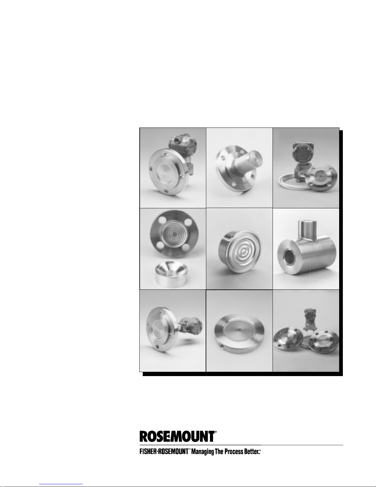
Cover Photos: 1199-039AB, 034AB, 051AB, 041AB, 077AB, 074AB, 038AB, 042AB, 063AB.
Fisher-Rosemount satisfies all obligations coming from legislation
to harmonize product requirements in the European Union.


Table of Contents
SECTION 1
Introduction
SECTION 2
Installation
SECTION 3
Calibration
Introduction . . . . . . . . . . . . . . . . . . . . . . . . . . . . . . . . . . . . . . . . 1-1
Seals Handling and Installation Considerations . . . . . . . . . . . 2-1
Tagging . . . . . . . . . . . . . . . . . . . . . . . . . . . . . . . . . . . . . . . . . . . . 2-2
Flanged Type Seals: Flush or Extended Diaphragm . . . . . . . . 2-2
Pancake Type Seals . . . . . . . . . . . . . . . . . . . . . . . . . . . . . . . . . . 2-3
Threaded Type Seals . . . . . . . . . . . . . . . . . . . . . . . . . . . . . . . . . 2-4
Saddle Type Seals . . . . . . . . . . . . . . . . . . . . . . . . . . . . . . . . . . . . 2-5
In-line Flow-Through Seals . . . . . . . . . . . . . . . . . . . . . . . . . . . . 2-5
Sanitary Tank Spud Seals . . . . . . . . . . . . . . . . . . . . . . . . . . . . . 2-6
Sanitary Flanged Tank Spud Seals . . . . . . . . . . . . . . . . . . . . . . 2-6
Sanitary Tri-Clamp
Sanitary Threaded Type Seals . . . . . . . . . . . . . . . . . . . . . . . . . . 2-7
Application Considerations . . . . . . . . . . . . . . . . . . . . . . . . . . . . 3-1
Zero Suppression . . . . . . . . . . . . . . . . . . . . . . . . . . . . . . . . . . . . 3-1
Zero Elevation . . . . . . . . . . . . . . . . . . . . . . . . . . . . . . . . . . . . . . . 3-1
Maximum Span Calculation . . . . . . . . . . . . . . . . . . . . . . . . . . . . 3-1
Electronics Considerations . . . . . . . . . . . . . . . . . . . . . . . . . . . . . 3-2
Maximum Span . . . . . . . . . . . . . . . . . . . . . . . . . . . . . . . . . . . . . . 3-2
Calibrating a One Seal System with Suppressed Zero
(Transmitter Mounted Below the High Side Tap) . . . . . . . . . . 3-3
Calibrating a One-Seal System with Elevated Zero
(Transmitter Mounted Above the High Side Tap) . . . . . . . . . . 3-4
Calibrating a Two-Seal System with Elevated Zero
(Transmitter Mounted Level with, Above, or Below
the High Pressure Tap) . . . . . . . . . . . . . . . . . . . . . . . . . . . . . . . 3-5
®
Seals . . . . . . . . . . . . . . . . . . . . . . . . . . . . 2-7
SECTION 4
Maintenance and
Troubleshooting
Cleaning . . . . . . . . . . . . . . . . . . . . . . . . . . . . . . . . . . . . . . . . . . . 4-1
Troubleshooting . . . . . . . . . . . . . . . . . . . . . . . . . . . . . . . . . . . . . 4-1
Return of Materials . . . . . . . . . . . . . . . . . . . . . . . . . . . . . . . . . . 4-2
iii

iv

Section
1 Introduction
Introduction
A diaphragm seal system consists of a pressure transmit te r, a
diaphragm seal, a fill fluid, and either a direct mount or capillary style
connection.
During operation, the thin, flexible diaphragm and fill fluid separate
the pressure sensitive element of the transmitter from the process
medium. The capillary tubing or direct mount flange connects the
diaphragm to the transmitter.
When process pressure is applied, the diaphragm is displaced,
transferring the measured pressure through the filled system, by way
of the capillary tubing, to the transmitter element. This transferred
pressure displaces the s ensing diaphragm in the pressure-sensitive
element of the transmitter. This displacement is proportional to the
process pressure and is converted electronically to an appropriate
current, voltage, or digital HART
Transducer) output signal.
This manual is designed to assist in installing, operating, and
maintaining the Rosemount Model 1199 Filled Systems for Pressure
Transmitters. The manual contains supplemental information about
the transmitter/seal system that is not covered in the correlative
transmitter manual.
The information is organized into the following categories:
• Installation
• Calibration
• Maintenance/Troubleshooting
See Product Data Sheets 00813-0100-4016 in North America or
00813-0201-4016 in Europe for more detailed information on specific
Rosemount diaphragm seals.
(Highway Addressable Remote
1-1

Model 1199 Diaphragm Seal Systems Manual
1-2
 Loading...