

Page 1
00809-0100-4360
English
Rev. AA
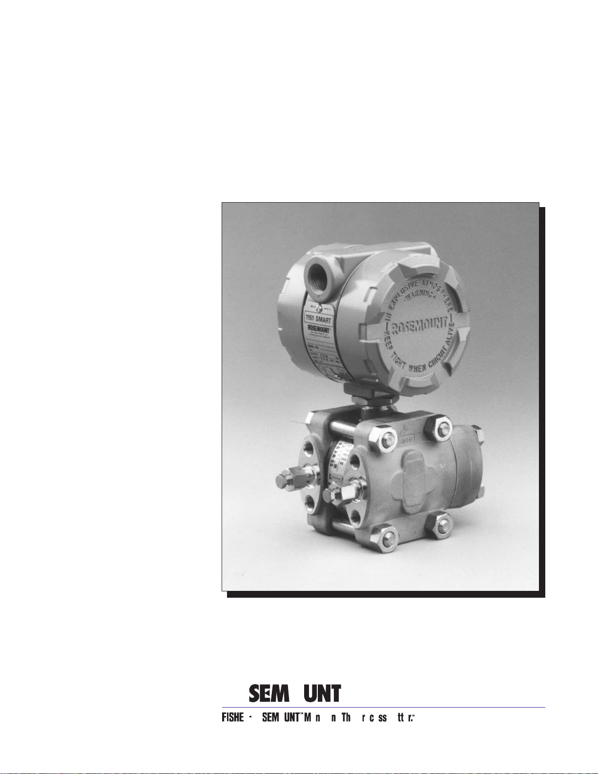
Model 1151
Alphaline® Pressure
Transmitters
Page 2

Page 3

Product Manual
Model 1151 Alphaline® Pressure
Transmitters
NOTICE
Read this manual before working with the prod uc t. For perso nal and system
safety, and for optimum product performance, make sure you thoroughly
understand the conten ts before installing, using, or maintaining this product.
Within the United States, Rosemount Inc. ha s two tol l-free assistance numbers.
Customer Central: 1-800-999-9307 (
Technical support, quoting, and order-related questions.
North American 1-800-654-7768 (
Response Center: Equipment service needs.
For equipment s ervice or s upport n eeds outs ide th e United State s, cont act your
local Rosemount representative.
7:00 a.m. to 7:00 p.m. CST)
24 hours a day – Includes Canada)
Rosemount In c.
8200 Market Boulevard
Chanhassen, MN 55317 USA
Tel 1-800-999-9307
Telex 4310012
Fax (612) 949-7001
© 1997 Rosemount, Inc.
http://www.rosemount.com
The products described in this document are NOT designed for nuclearqualified applications.
Using non-nuclear qua lifi ed products in applications that require nuclearqualified hardware or products may cause inaccurate readings.
For information on Rosemount nucle ar-qualified products, contact you r local
Rosemount Sales Representative.
May be protected by one or more of the following U.S. Patent Nos. 3,195 ,028; 3,271,669; 3,318,15 3;
3,618,390; 3,646,538; 3,793,885; 3,800,413; 3,854,039; 3,859,594; 3,975,719; 4,339,750; 5,237,285;
Re. 30,603. May Depend on Model. Other U.S. and Foreign Patents Issued and Pending.
Rosemount, the Rosemount logotyp e, Alphaline, and SMART FAMILY are registered trademarks of
Rosemount Inc.
HART is a registered trademark of the HART Communication Foundation.
d
-Cell is a trademark of Rosemount Inc.
Hastelloy, Hastelloy C, and Hastelloy C-276 are registered trademarks of Cabot Corp.
Monel is a registered trademark of International Nickel Co.
Teflon is a registered trademark of E.I. du Pont de Nemours & Co.
Aflas is a registered trademark of Asahi Glass Co., Ltd.
Kynar is a trademark of Pennwalt Inc.
Flourolube is a registered trademark of Hooker Chemical Co.
Loctite is a registered trademark of Loctite Corporation.
Cover Photo: 1151-001AB
Fisher-Rosemount satisfies all obligations coming from legislation
to harmonize product requ ireme n ts in th e Euro pe a n Union.
T
N
I
E
D
R
P
IN
U.
A.
S.
SNF-0004
Page 4

Page 5

Table of Contents
Introduction
Installation
Using This Manua. . . . . . . . . . . . . . . . . . . . . . . . . . . . . . . . . . . . . . 9
Model 1151 Alphaline® Pressure Transmitters . . . . . . . . . . . . . . 9
Transmitter overview . . . . . . . . . . . . . . . . . . . . . . . . . . . . . . . . . . 10
General Considerations . . . . . . . . . . . . . . . . . . . . . . . . . . . . . . . . . 11
Mechanical Considerations. . . . . . . . . . . . . . . . . . . . . . . . . . . . . . . 11
Environmental Requirements . . . . . . . . . . . . . . . . . . . . . . . . . . . 13
Access Requirements . . . . . . . . . . . . . . . . . . . . . . . . . . . . . . . . 13
Process Flange Orientation . . . . . . . . . . . . . . . . . . . . . . . 13
Housing Rotation . . . . . . . . . . . . . . . . . . . . . . . . . . . . . . . . 13
Terminal Side of Electronics Housing . . . . . . . . . . . . . . . 13
Circuit Side of Electronics Housing . . . . . . . . . . . . . . . . . 13
Exterior of Electronics Housing . . . . . . . . . . . . . . . . . . . 13
Mounting Effects. . . . . . . . . . . . . . . . . . . . . . . . . . . . . . . . . . . 14
Process Connections . . . . . . . . . . . . . . . . . . . . . . . . . . . . . . . . 14
Mounting Brackets . . . . . . . . . . . . . . . . . . . . . . . . . . . . . . . . . 15
Mounting Requirements (for Steam, Liquid, Gas) . . . . . . . . 17
Taps . . . . . . . . . . . . . . . . . . . . . . . . . . . . . . . . . . . . . . . . . . 17
Drain/Vent Valves . . . . . . . . . . . . . . . . . . . . . . . . . . . . . . . 17
Impulse Piping . . . . . . . . . . . . . . . . . . . . . . . . . . . . . . . . . 18
Electrical Considerations . . . . . . . . . . . . . . . . . . . . . . . . . . . . . . . . 18
Wiring . . . . . . . . . . . . . . . . . . . . . . . . . . . . . . . . . . . . . . . . . . . 19
Conduit Sealing . . . . . . . . . . . . . . . . . . . . . . . . . . . . . . . . . . . 20
Power Supply . . . . . . . . . . . . . . . . . . . . . . . . . . . . . . . . . . . . . 20
Grounding . . . . . . . . . . . . . . . . . . . . . . . . . . . . . . . . . . . . . . . . 22
Signal Wiring . . . . . . . . . . . . . . . . . . . . . . . . . . . . . . . . . . . 22
Transmitter Case . . . . . . . . . . . . . . . . . . . . . . . . . . . . . . . 22
Grounding Effects . . . . . . . . . . . . . . . . . . . . . . . . . . . . . . . 22
Hazardous Locations Certifications. . . . . . . . . . . . . . . . . . . . 24
Liquid Level Measurement . . . . . . . . . . . . . . . . . . . . . . . . . . . . . . 24
Open Vessels . . . . . . . . . . . . . . . . . . . . . . . . . . . . . . . . . . . . . . 24
Closed Vessels . . . . . . . . . . . . . . . . . . . . . . . . . . . . . . . . . . . . . 24
Dry Leg Condition . . . . . . . . . . . . . . . . . . . . . . . . . . . . . . . 24
Wet Leg Condition . . . . . . . . . . . . . . . . . . . . . . . . . . . . . . . 25
Bubbler System in Open Vessel . . . . . . . . . . . . . . . . . . . . 26
Calibration
Quick Calibration Procedure (for E, G, and J Electronics). . . . . 29
Quick Calibration Procedure (For L and M Electronics) . . . . . . 29
Data Flow with Calibration Options . . . . . . . . . . . . . . . . . . . . . . 31
Span Adjustment Range . . . . . . . . . . . . . . . . . . . . . . . . . . . . . . . . 32
Zero Adjustment Range . . . . . . . . . . . . . . . . . . . . . . . . . . . . . . . . 32
Zero and Span Adjustment . . . . . . . . . . . . . . . . . . . . . . . . . . . . . . 34
Elevated or Suppressed Zeros . . . . . . . . . . . . . . . . . . . . . . . . . . . 35
Linearity Adjustment . . . . . . . . . . . . . . . . . . . . . . . . . . . . . . . . . . 35
Damping Adjustment . . . . . . . . . . . . . . . . . . . . . . . . . . . . . . . . . . 36
Static Pressure Span Correction Factor . . . . . . . . . . . . . . . . . . . . 37
i
Page 6

Options
Mounting Brackets . . . . . . . . . . . . . . . . . . . . . . . . . . . . . . . . . . . . . 39
(Option Codes B1–B7 and B9) . . . . . . . . . . . . . . . . . . . . . 39
Analog Meters (4–20 ma only) . . . . . . . . . . . . . . . . . . . . . . . . . . . 41
LCD Meters (4–20 ma only) . . . . . . . . . . . . . . . . . . . . . . . . . . . . . 41
LCD Meter Configuration . . . . . . . . . . . . . . . . . . . . . . . . . . . 41
Remove the Cove . . . . . . . . . . . . . . . . . . . . . . . . . . . . . . .r 42
Position the Decimal Point and Select the Meter Function 42
Store the Information. . . . . . . . . . . . . . . . . . . . . . . . . . . . 43
Set the Display Equivalent to a 4 mA Signal . . . . . . . . . 43
Set the Display Equivalent to a 20 mA Signal. . . . . . . . 43
Replace the Cover. . . . . . . . . . . . . . . . . . . . . . . . . . . . . . . 43
LCD Meter Assembly . . . . . . . . . . . . . . . . . . . . . . . . . . . . . . . 43
LCD Meter Specifications . . . . . . . . . . . . . . . . . . . . . . . . . . . 44
Terminal Blocks. . . . . . . . . . . . . . . . . . . . . . . . . . . . . . . . . . . . . . . 45
Filter Terminal Block (Option Code R2) . . . . . . . . . . . . . . . . 46
Transient Protection and Filter Terminal Block
(Option Code R1) . . . . . . . . . . . . . . . . . . . . . . . . . . . . . . . . . . 46
Retrofitable Transient Terminal Block(Option Code R9). . . 46
R9 Terminal Block Installation . . . . . . . . . . . . . . . . . . . . 47
Terminal Block Specifications (for R1, R2, and R9) . . . . . . . 49
Maintenance and
Troubleshooting
Specifications and
Reference Data
Hardware Diagnostics. . . . . . . . . . . . . . . . . . . . . . . . . . . . . . . . . . 51
Transmitter Disassembly . . . . . . . . . . . . . . . . . . . . . . . . . . . . . . . 54
54
Process Sensor Body Removal 55
Removing the Sensor from the Electrical Housing . . . . 56
Sensor Module Checkout . . . . . . . . . . . . . . . . . . . . . . . . . 57
Reassembly Procedure . . . . . . . . . . . . . . . . . . . . . . . . . . . . . . . . . 58
Preliminary Precaution . . . . . . . . . . . . . . . . . . . . . . . . . . . . . 58
Connecting the Electrical Housing to the Sensor. . . . . . . . . 58
Backup Ring and O-ring Installation . . . . . . . . . . . . . . . . . . 58
Optional Plug-in Meter. . . . . . . . . . . . . . . . . . . . . . . . . . . . . .s 60
Return of Material . . . . . . . . . . . . . . . . . . . . . . . . . . . . . . . . . . . . 60
Functional Specifications . . . . . . . . . . . . . . . . . . . . . . . . . . . . . . . 61
Performance Specifications. . . . . . . . . . . . . . . . . . . . . . . . . . . . . . 66
Physical Specifications (Standard Configuration). . . . . . . . . . . . 68
ii
Page 7

Section
1 Introduction
USING THIS MANUAL
This manual is designed to assist in installing, operating, and
maintaining the Rosemount Model 1151 Analog Pressure Transmitter
Family.
Section 2 Installation
provides mechanical and electrical installation instructions.
Section 3 Calibration
explains technique for calibration of the device.
Section 4 Options
explains the options available for the Model 1151, including mounting
brackets, LCD meters, custom configuration, transient protection, and
filter terminal blocks.
Section 5 Maintenance and Troubleshooting
describes trim procedures and offers troubleshooting instructions for
dealing with potential mechanical or electrical difficulties.
Section 6 Specifications and Reference Data
lists functional, performance, and physical specifications data as well
as ordering information for the transmitter.
Appendix A Approval Drawings
contains approval drawings for Canadian Standards Association (CSA)
and Factory Mutual (FM) intrinsic safety drawings.
Glossary
provides brief definitions of the terms use d in this manual and tells
where to find more information.
MODEL 1 151 ALPHALINE®
PRESSURE
TRANSMITTERS
Index
contains a comprehensive, standard index.
This manual describes the following Model 1151 Alphaline® Pressure
Transmitters.
• Model 1151DP— Differential Pressure Transmitter
measures differential pressure from 6 inH
(1.493 to 6895 kPa).
• Model 1151HP— Differential Pressure Transmitter
for High Line Pressures measures high line pressures from
25 inH
• Model 1151GP— Gage Pressure Transmitter
measures gage pressure from 6 inH
41369 kPa).
• Model 1151AP— Absolute Pressure Transmitter
measures absolute pressure from 25 inH
6895 kPa).
O to 300 psi (6.22 to 2668 kPa).
2
2
O to 6,000 psi (1.493 to
O to 1,000 psi
2
O to 1,000 psi (6.22 to
2
1-1
Page 8

Model 1151 Alphaline® Pressure Transmitters
TRANSMITTER OVERVIEW
The Rosemount Model 1151 Alphaline® series of pressure transmitters
has set an industry standard as the largest-selling transmitter in the
world. It brings true precision to the measurement of flow, level, gage
and absolute pressures, vacuum, and specific gravity.
With proven performance, quality, and reliability, the Model 1151
provides accurate measurement using the variable capacitance
principle. It is virtually unaffected by changes in temperature, static
pressure, vibration, and power supply voltage.
Installation, calibration, and commissioning are simplified by the
transmitter’s compact design, integral junction box, and local span and
zero adjustments. Its modular design and high degree of
interchangeability result in a minimal investment for spare parts.
1-2
Page 9

Section
2 Installation
This section covers areas to consider when installing the Model 1151
Analog Transmitter:
• General Considerations
• Mechanical Considerations
• Environmental Requirements
• Electrical Considerations
• Liquid Level Measurement
GENERAL
CONSIDERATIONS
MECHANICAL
CONSIDERATIONS
The accuracy of a flow, pressure, or level measurement depends on
proper installation of the transmitter and impulse piping. The piping
between the process and transmitter must accurately transmit process
pressure to the transmitter. Mount the transmitter close to the process
and use a minimum of piping to achieve best accuracy. Keep in mind,
however, the need for easy access, safety of personnel, practical field
calibration, and a suitable transmitter environment. In general, install
the transmitter so as to minimize vibration, shock, and temperature
fluctuations.
Installations in food, beverage, and pharmaceutical processes may
require sanitary seals and fittings. Regulations may dictate special
installation requirements needed to maintain sanitation and
cleanability considerations. See Product Data Sheet 00813-0100-4016
for more information about sanitary pressure instruments from
Rosemount Inc.
Rosemount Model 1151DP, GP, HP, and AP transmitters may be
mounted in several ways. They may be panel-mounted, wall-mounted,
or attached to a 2-inch pipe through an optional mounting bracket.
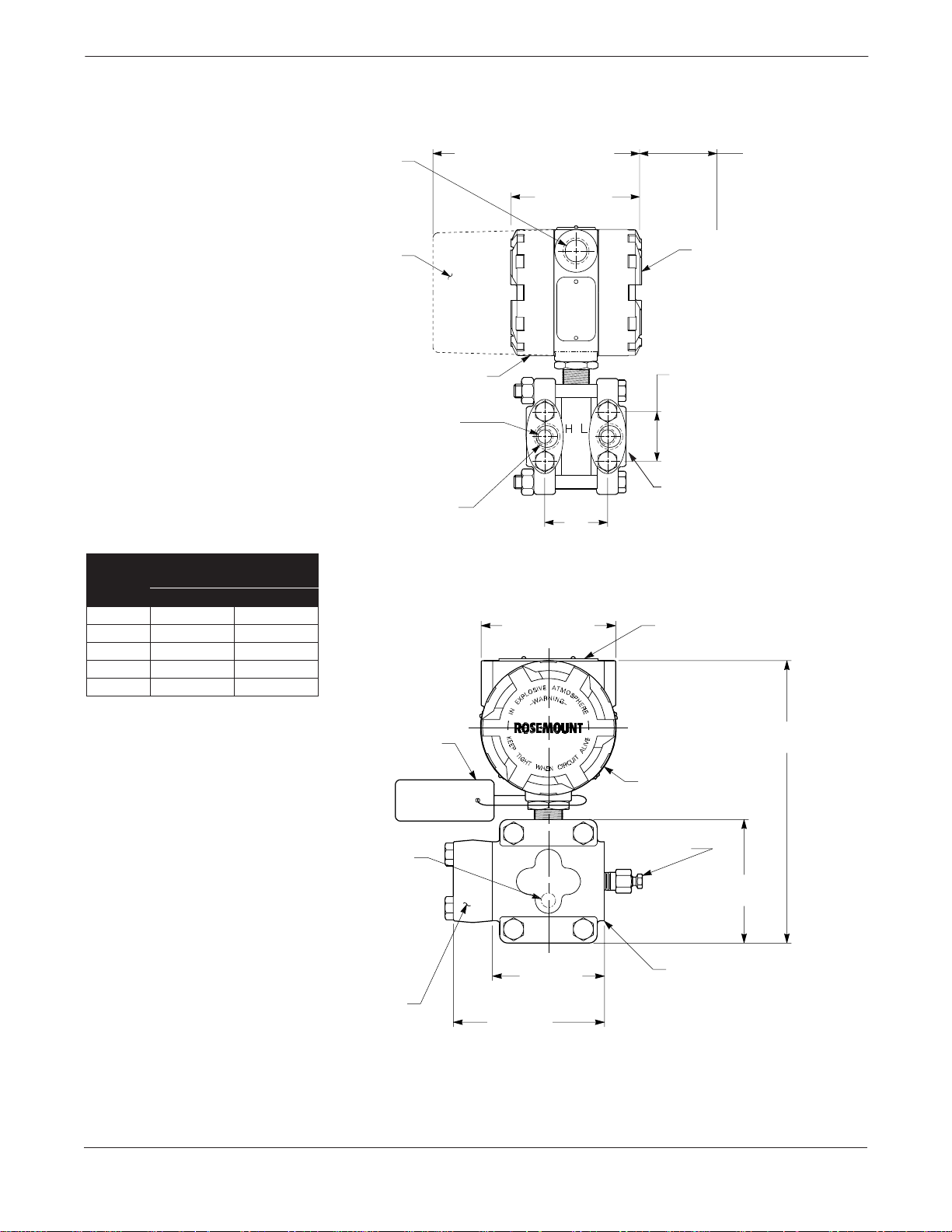
Figure 2-1 shows the transmitter dimensions. The following
paragraphs discuss factors necessary for a successful transmitter
installation.
2-1
Page 10
Model 1151 Alphaline® Pressure Transmitters
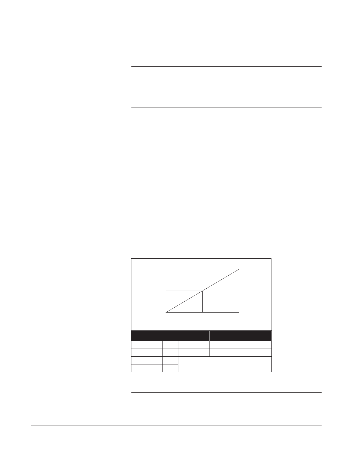
FIGURE 2-1. Dimensional Drawing
for Model 1151 Transmitter.
Flange Distance “A”
Range
3, 4, 5 2.125 54
6, 7 2.188 56
82.250 57
92.281 58
02.328 59
Center to Center
inches mm
½–14 NPT
Conduit
Connection
(2 Places)
Meter
Housing
Terminal Connections
This Side
¼–18 NPT on
Flanges for Pressure
Connection without
Flange Adapters
½–14 NPT on
Flange
Adapters
7.5 (191) Max.
with Optional Meter
4.5 (114)
Max.
A
(See Table)
4.5 (114)
Max.
0.75 (19)
Clearance for
Cover Removal
(Typical)
Transmitter
Circuitry
This Side
1.625
(41)
Blank Flange
Used on
AP and GP
Transmitters
Permanent
Tag (Optional)
NOTE
Dimensions are in inches (millimeters).
2-2
Wired-on
(Standard)
¼–18 NPT for
Side Drain/Vent
(Optional Top
or Bottom)
Flange
Adapter
Tag
4.5 (114)
3.375
(86)
9.0 (229) Max.
Nameplate
Drain/Vent
Valve
3.69
(94)
Flanges Can
Be Rotated
1151-1151A,B05A
Page 11

Installation
ENVIRONMENTAL
REQUIREMENTS
Mount the transmitter to minimize ambient temperature changes. The
transmitter electronics temperature operating limits are –40 to 200 °F
(–40 to 85 °C) for “E” output options, –20 to 150 °F (–29 to 66 °C) for “J”
output options, and –20 to 200 °F (–29 to 93 °C) for G, L, and M output
options. Section 5 Maintenance and Troubleshooting lists the
sensing element operating limits. Mount the transmitter to avoid
vibration and mechanical shock, and to avoid external contact with
corrosive materials.
Access Requirements
When choosing an installation location and position, take into account
the need for access to the transmitter.
Process Flange Orientation Orient the process flanges to enable process connections to be made.
For safety reasons, orient the drain/vent valves so that process fluid is
directed down and away from technicians when the valves are used.
This can be accomplished by pointing the hole in the outside valve body
downward and away. In addition, consider the need for a testing or
calibration input.
Do not rotate the transmitter housing more than 90 degrees
without disconnecting the header board. Exceeding 90
degrees rotation will damage the internal sensor module
wiring. Refer to Removing the Sensor from the Electrical
Housing on page 5-6 for further information.
Housing Rotation The electronics housing may be rotated up to 90 degrees to improve
field access to the two housing compartments. T o rotate the housing less
than 90 degrees, loosen the housing lock nut and turn the housing not
more than 90 degrees from the orientation shown in Figure 2-1. To
rotate the housing more than 90 degrees, follow th e transmitter
disassembly procedures in Section 5 Maintenance and
Troubleshooting.
Terminal Side of
Electronics Housing
Make wiring connections through the conduit openings on the top side
of the housing. The terminal side of the housing is marked on the
nameplate located on the side of the transmitter. Mount the transmitter
so that the terminal side is accessible. A ¾-inch clearance is required
for cover removal with no meter. A 3-inch clearance is required for cover
removal if a meter is installed. If practical, provide approximately 6
inches clearance so that a meter may be installed later.
Circuit Side of
Electronics Housing
The circuit compartment should not routinely need to be opened when
the unit is in service; however, provide 6 inches clearance if possible to
allow access for on-site maintenance. The circuit side of the housing is
marked on the nameplate located on the side of the transmitter.
Exterior of Electronics Housing The analog Model 1151 uses local span and zero screws, which are
located under the nameplate on the side of the transmitter . Please allow
6 inches clearance if possible to allow access for on-site maintenance.
2-3
Page 12

Model 1151 Alphaline® Pressure Transmitters
Mounting Effects
The analog Model 1151 weighs 12 lb (5.4 kg) for AP, DP, GP, and HP
transmitters, excluding options. This weight must be securely
supported; see Figure 2-2 on page 2-6 for mounting bracket
information. The transmitter is calibrated in an upright position at the
factory. If this orientation is changed during mounting, the zero point
will shift by an amount equivalent to the liquid head caused by the
mounting position. Zero and Span Adjustment on page 3-6 describes
how to correct this shift.
Process leaks can cause death or serious injury. Only use
bolts supplied with the transmitter or sold by Rosemount
Inc. as a spare part. Using unauthorized bolts may reduce
pressure retaining capabilities and render the instrum ent
dangerous.
Do not plug the low side with a solid plug. Plugging the low
side will cause an output shift.
Process Connections
Model 1151AP, DP, GP, and HP process connections on the transmitter
flanges are ¼–18 NPT. Flange adapter unions with ½–14 NPT
connections are supplied as standard. These are Class 2 threads; use
plant-approved lubricant or sealant when making the process
connections. The flange adapters allow users to disconnect from the
process by removing the flange adapter bolts. Figure 2-1 on page 2-2
shows the distance between pressure connections. This distance may be
1
varied ±
/8 inch (3.2 mm) by rotating one or both of the flange adapters.
To ensure a tight seal on the flange adapters or three-valve manifold,
first finger-tighten both bolts, then wrench-tighten the first bolt to
approximately 29 ft-lbs (34 Nm). Wrench-tighten the second bolt to
approximately 29 ft-lbs (34 Nm).
2-4
Page 13
Process leaks can cause death or serious injury. Install and
tighten all four flange bolts before applying pressure, or
process leakage may result. When properly installed, the
flange bolts will protrude through the top of the module
housing. Attempting to remove the flange bolts while the
transmitter is in service may cause process fluid leaks.
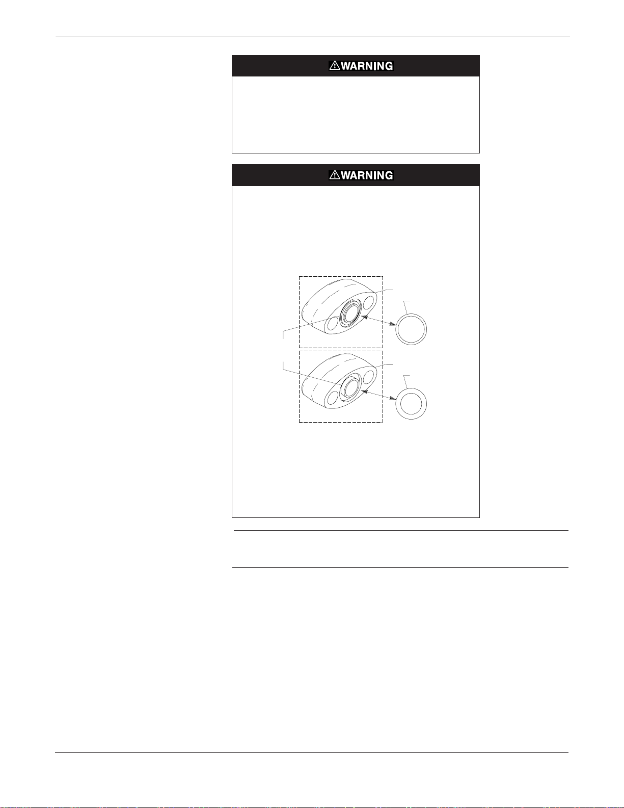
Failure to install flange adapter O-rings can cause process
leaks, which can result in death or serious injury.
There are two styles of Rosemount flange adapters, each
requiring a unique O-ring, as shown below. Each flange
adapter is distinguished by its unique groove.
MODEL 3051/2024/3001/3095
Flange Adapter
O-ring
Installation
Unique O-ring
Grooves
Flange Adapter
O-ring
MODEL 1151
Use only the O-ring designed to seal with the corresponding
flange adapter.
Refer to the Spare Parts List on page 6-13 for the part
numbers of the flange adapters and O-rings designed for
the Model 1151 Pressure Transmitter.
NOTE
If Teflon O-rings are used, they should be replaced if the f lange adapter
is removed.
The low-side process flange has a ¼–18 NPT connection. A flange
adapter union is supplied for ½–14 NPT process connections. The
flange adapter allows the transmitter to be easily disconnected from the
process by removing the flange adapter bolts. On open vessels the lowside process flange is open to atmosphere and should be mounted with
the threaded hole pointed down. On closed vessels this connection is
used for the dry or wet leg.
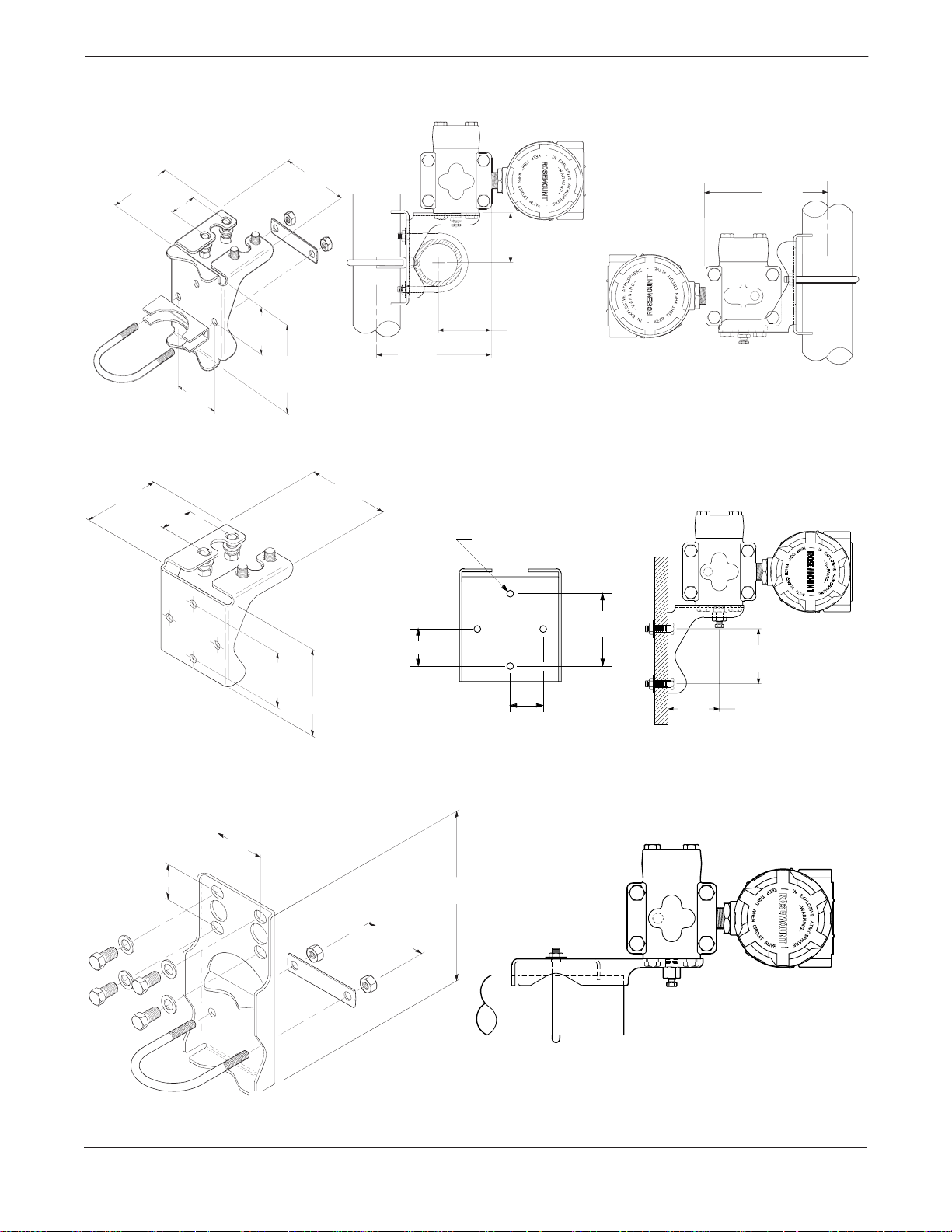
Mounting Brackets
An optional mounting bracket permits mounting the transmitter to a
wall, a panel, or a 2-inch horizontal or vertical pipe. Figure 2-2
illustrates some typical configurations using these mounting brackets.
2-5
Page 14
Model 1151 Alphaline® Pressure Transmitters
FIGURE 2-2. Mounting Bracket
Options.
3.75
(95)
3.75 (95)
1.65 (42)
2.81
(71)
1.65 (42)
3.87
(98)
2.625 (67)
2.62
(67)
4.97
(127)
5.625
(143)
2.625
(67)
PIPE MOUNTING BRACKET OPTION CODES B1, B4, AND B7
3.87 (98)
Mounting Holes
0.375 Diameter
(10)
2.81 Typ.
(71)
1.40 (46)
2.81 Typ.
(71)
4.5 (114)
1.40
(36)
PANEL MOUNTING BRACKET OPTION CODES B2 AND B5
5.625
(143)
3051-3051D19A, 1151-1151D,B06C
2.81 Typ.
(71)
2.625
(67)
3051-3051B19A, 1151-0244A, 1151-1151E06A
2.125 (54)
1.62 (41)
NOTE
Dimensions are in inches (millimeters).
2-6
8 (203)
2.81 (71)
FLAT MOUNTING BRACKET OPTION CODES B3, B6, AND B9
3051-3051H19B, 1151-1151F06B
Page 15
Installation
Mounting Requirements
The following information applies to steam, liquid, and gas installations.
(for Steam, Liquid, Gas)
Taps Different measurement conditions call for different piping
configurations. For liquid flow measurement, place taps to the side of
the line to prevent sediment deposits, and mount the transmitter beside
or below these taps so gases can vent into the process line. For gas flow
measurement, place taps in the top or side of the line and mount the
transmitter beside or above the taps so liquid will drain into the process
line. For steam flow measurement, place taps to the side of the line with
the transmitter mounted below them to ensure that the impulse piping
stays filled with condensate. See Figure 2-3 for a diagram of these
arrangements.
FIGURE 2-3. Steam, Liquid, and
Gas Service Installation Diagrams.
Blocking
Flow
Valves
Plugged Tee
for Steam Service
for Sealing Fluid
Optional Side-
mounted Drain/
Vent Valve
LIQUID SERVICE
L
H
3-valve
Manifold
GAS SERVICE
H
Vent/Drain
Valve
L
Sufficient
Length for
Cooling
H
L
STEAM SERVICE
3-valve
Manifold
NOTE
For steam service do not blow down impulse piping
through transmitter. Flush lines with blocking valves closed
and refill lines with water before resuming measurement.
Flow
3-valve
Manifold
Flow
Flow
H
L
Drain/Vent
Valve
3-valve
Manifold
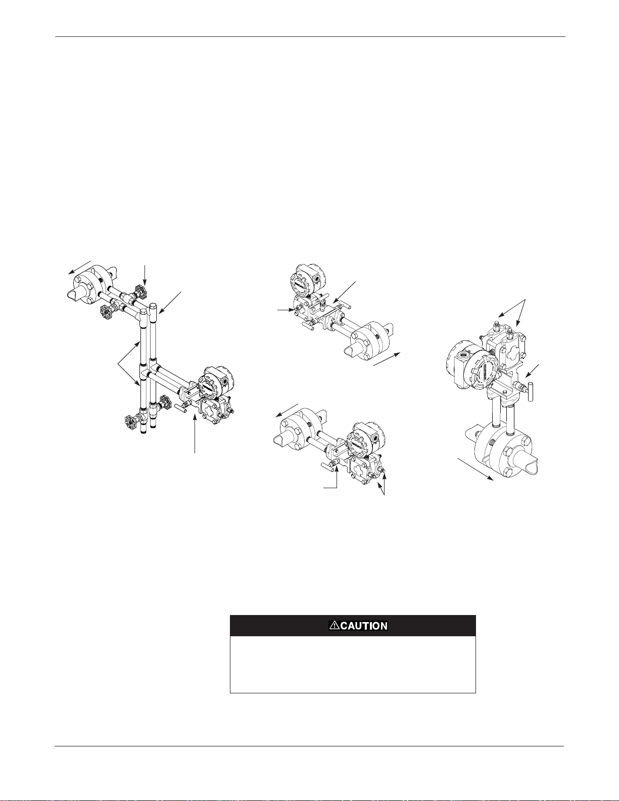
Drain/Vent Valves For transmitters with side drain/vent valves, place taps to the side of
the line. For liquid service, mount the side drain/vent valve upward to
allow the gases to vent. For gas service, mount the drain/vent valve
down to allow any accumulated liquid to drain. T o change the drain/vent
valve orientation from top to bottom, rotate the process flange 180
degrees.
1151-1151D,A,B,C01A
Steam or other elevated temperature processes can cause
damage to the sensor. Do not allow the temperature inside
the process flanges to exceed the transmitter limit of 220 °F
(104 °C).
In steam service, lines should be filled with water to prevent contact of
the live steam with the transmitter.
2-7
Page 16

Model 1151 Alphaline® Pressure Transmitters
Impulse Piping The piping between the process and the transmitter must accurately
transfer the pressure in order to obtain accurate measurements. In this
pressure transfer , there are five possible sources of error: leaks, friction
loss (particularly if purging is used), trapped gas in a liquid line, liquid
in a gas line, and temperature-induced or other density variation
between the legs.
The best location for the transmitter in relation to the process pipe
depends on the process itself. Co nsider th e f ollowing gene ral guidelines
in determining transmitter location and placement of impulse piping:
• Keep impulse piping as short as possible.
• Slope the impulse piping at least 1 inch per foot (8 centimeters
per meter) upward from the transmitter toward the process
connection for liquid.
• Slope the impulse piping at least 1 inch per foot (8 centimeters
per meter) downward from the transmitter toward the process
connection for gas.
• Avoid high points in liquid lines and low points in gas lines.
• Make sure both impulse legs are the same temperature.
• Use impulse piping large enough to avoid friction effects and
prevent blockage.
• Vent all gas from liquid piping legs.
• When using a sealing fluid, fill both piping legs to the same level.
• When purging is necessary, make the purge connection close to
the process taps and purge through equal lengths of the same size
pipe. Avoid purging through the transmitter.
• Keep corrosive or hot process material out of direct contact with
the sensor module and flanges.
• Prevent sediment deposits in the impulse piping.
• Keep the liquid head balanced on both legs of the impulse piping.
ELECTRICAL
CONSIDERATIONS
2-8
Before making any electrical connections to the Model 1151 analog,
consider the following standards and be sure to have proper power
supply, conduit, and other accessories. Make sure all electrical
installation is in accordance with national and local code requirements,
such as the NEC (NFPA 70).
Explosions can cause death or serious injury. Do not
remove the instrument cover in explosive atmospheres
when the circuit is alive.
Do not connect the power signal wiring to the test terminals.
Voltage may burn out the reverse-polarity protection diode
in the test connection. If the test diode is destroyed, then the
transmitter can still be operated without local indication by
jumping the test terminals.
Page 17
High voltage (greater than 55 Volts for “E” electronics, 85
Volts for “G” electronics, 12 Volts for “L” electronics, and 14
Volts for “M” electronics.) can cause damage to the
transmitter. Do not apply high voltage to the test terminals.
Installation
Wiring
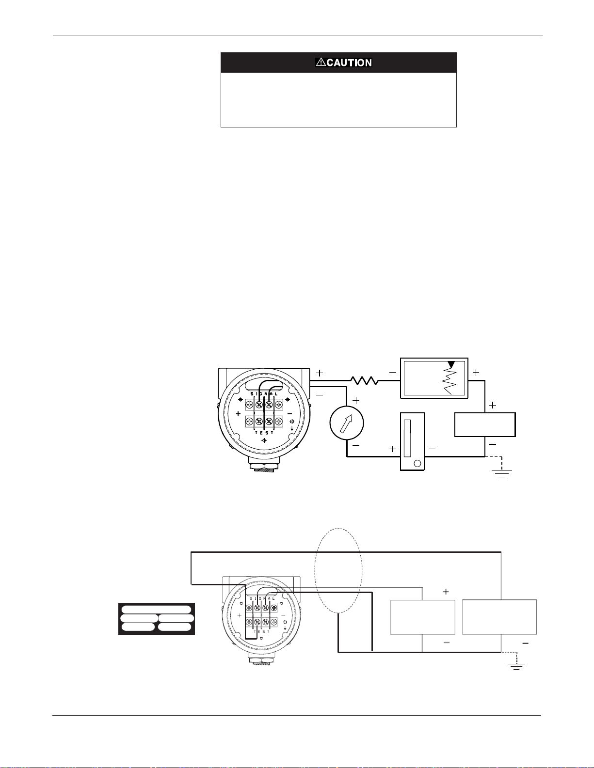
FIGURE 2-4. Terminal Connections.
The signal terminals and test terminals are located in a compartment
of the electronics housing separate from the transmitter electronics.
The nameplate on the side of the transmitter indicates the locations of
the terminal and electronics compartments. The upper pair of
terminals are the signal terminals and the lower pair are the test
terminals. The test terminals have the same 4–20 mA output as the
signal terminals and are only for use with the optional integral meter
or for testing.
To make connections, remove the cover on the side marked “Terminal”
on the nameplate. All power to the transmitter is supplied over the
signal wiring. Connect the lead that originates at the positive side of
the power supply to the terminal marked “+” and the lead that
originates at the negative side of the power supply to the terminal
marked “–” as shown in Figure 2-4. No additional wiring is required.
Shielded cable should be used for best results in electrically noisy
environments.
POWER
SUPPL Y
FIGURE 2-5. Wiring Con nec tions for
Low Power Output Codes L and M.
Terminal
+
Common
Case
+ Power
Signal
Field Wiring
Label Detail
The signal loop may be grounded at
any point or left ungrounded.
Shield
Supply
Power
1151-1151G05A
A to D
Converter
1151-1151H05A
2-9
Page 18
Model 1151 Alphaline® Pressure Transmitters
NOTE
An alternate location to connect an ammeter is on the set of terminals
labelled “TEST.” Connect the positive lead of the ammeter to the
positive test terminal, and the negative lead of the ammeter to the
negative test terminal.
NOTE
When conduit lines are used, signal wiring need not be shielded, but
twisted pairs should be used for best results. Wiring should be 12-24
AWG.
Conduit Sealing
Power Supply
FIGURE 2-6. Power Supply Load
Limitations.
The 1151 has been rated as “Factory Sealed” by Factory Mutual (FM)
and Canadian Standards Association (CSA). It is therefore not
necessary to install conduit seals near the transmitter enclosure.
Do not run signal wiring in conduit or open trays with power wiring, or
near heavy electrical equipment. Signal wiring may be grounded at any
one point on the signal loop, or it may be left ung rounde d. The n egative
terminal of the power supply is a recommended grounding point. The
transmitter case must be grounded through the process or conduit
connections.
The dc power supply should provide power with less than 2 percent
ripple. The total resistance load is the sum of the resistance of the
signal leads and the load resistance of the controller, indicator, and
related pieces. Note that the resistance of intrinsic safety barriers, if
used, must be included.
To power the loop, connect the leads at the set of terminal screws
labeled “Signal.” Figure 2-6 illustrates power supply load limitations
for the transmitter:
R
max
2-10
R
L
R
min
V
min
Code V
E, J 12 45 0 1650 RL = 50 (VS – 12)
G 30 85 0 1100 R
L512
M814
minVmaxRminRmaxRL
Low Power Minimum Load Impedance:
V
S
Operating
Region
V
max
at Supply Voltage (VS)
= 20 (VS – 30)
L
100 kV
NOTE
For CSA Approvals (codes E and J), V
= 42.4 V dc.
max
Page 19
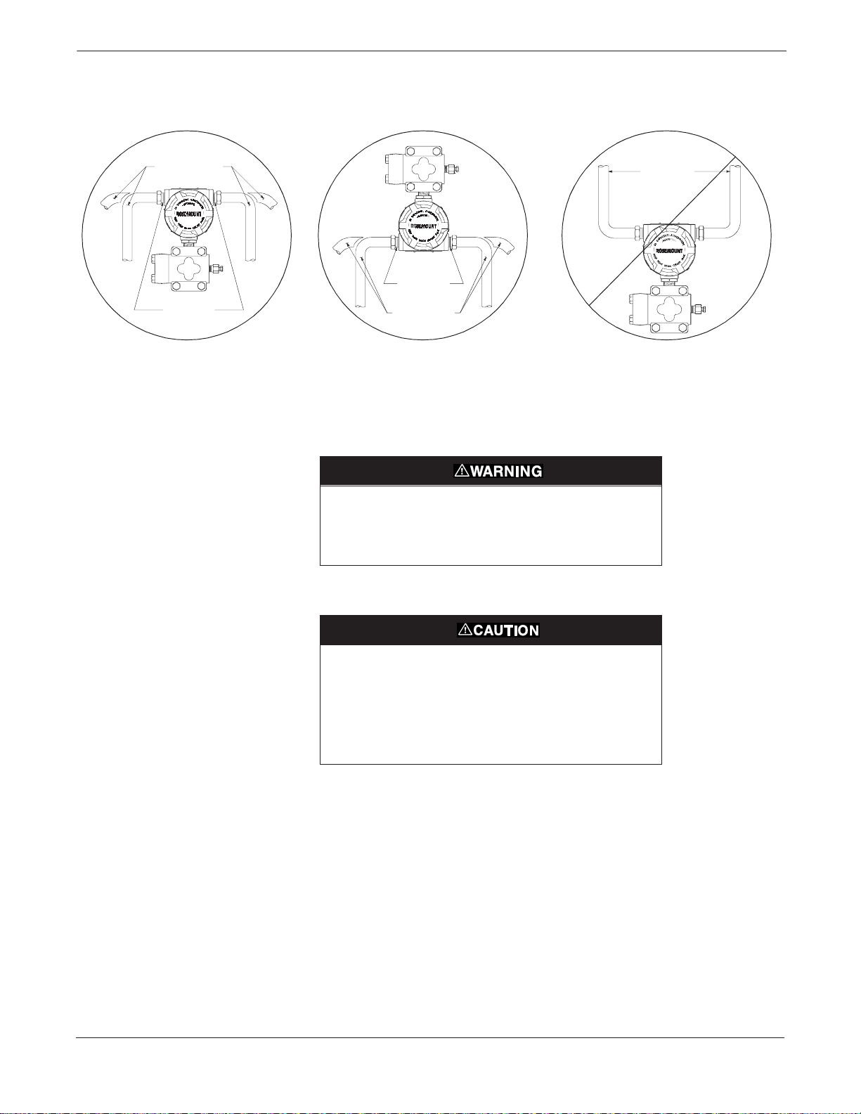
FIGURE 2-7. Conduit Installat ion
Diagrams.
Installation
Possible
Conduit Line
Positions
1151-1 151D25A
Sealing
Compound
CORRECT CORRECT INCORRECT
Sealing
Compound
Possible
Conduit Line
Positions
1151-1151E25A
Conduit
Lines
Unused conduit connections on the transmitter housing should be
plugged and sealed to avoid moisture accumulation in the terminal side
of the housing. The recommended connections of conduit are shown in
Figure 2-7.
All explosion proof, flameproof, and dust-ign ition proof
installations require insertion of conduit plugs in all unused
openings with a minimum of 40 ft-lbs (54 N-m) of torque.
This will maintain five full threads of engagement.
1151-1151F25A
If all connections are not sealed, excess moisture
accumulation can damage the transmitter. Make sure to
mount the transmitter with the electrical housing positioned
downward for drainage. To avoid moisture accumulation in
the housing, install wiring with a drip loop, and ensure the
bottom of the drip loop is mounted lower than the conduit
connections or the transmitter housing.
Grounding
Use the following techniques to properly ground the transmitter signal
wiring and case:
Signal Wiring Do not run signal wiring in conduit or open trays with power wiring, or
near heavy electrical equipment. Signal wiring may be grounded at any
one point on the signal loop, or it may be left ung rounde d. The n egative
terminal of the power supply is a recommended grounding point.
Transmitter Case The transmitter case must be grounded in accordance with national
and local electrical codes. The most effective transmitter case
grounding method is a direct internal connection to earth ground with
minimal impedance.
2-11
Page 20

Model 1151 Alphaline® Pressure Transmitters
Internal Ground Connection: Inside the FIELD TERMINALS side of
the electronics housing is the Internal Ground Connection screw. This
screw is identified by a ground symbol: .
NOTE
Grounding the transmitter case via threaded conduit connection may
not provide sufficient ground continuity.
NOTE
The transient protection terminal block (See Figure 4-4 on page 4-8)
does not provide transient protection unless the transmitter case is
properly grounded. Use the preceding guidelines to ground the
transmitter case.
Do not run the transient protection ground wire with signal wiring as
the ground wire may carry excessive current if a lightning strike occurs.
Grounding Effects The capacitance sensing module requires alternating current to
generate a capacitance signal. This alternating current is developed in
an oscillator circuit with a frequency of approximately 32 kHz. This
signal is capacitor-coupled to transmitter-case ground through the
sensing module. Because of this coupling, a voltage may be imposed
across the load, depending on the choice of grounding. See Figure 2-8.
Hazardous Locations
Certifications
This impressed voltage, which is seen as high frequency noise, will have
no effect on most instruments. Computers with short sampling times
will detect a significant noise signal, which should be filtered out by
using a large capacitor (1 µF) or by using a 32 kHz LC filter across the
load. Computers are negligibly affected by this noise and do not need
filtering
The Model 1151 was designed with an explosion-proof housing and
circuitry suitable for intrinsically safe and non-incendive operation.
Factory Mutual explosion-proof certification is standard for the Model
1151 Transmitter. Individual transmitters are clearly marked with a
tag indicating the approvals they carry. Transmitters must be installed
in accordance with all applicable codes and standards to maintain these
certified ratings. Refer to Hazardous Locations Certifications on
page 6-2 for information on the approvals associated with the analog
Model 1151.
.
2-12
Page 21
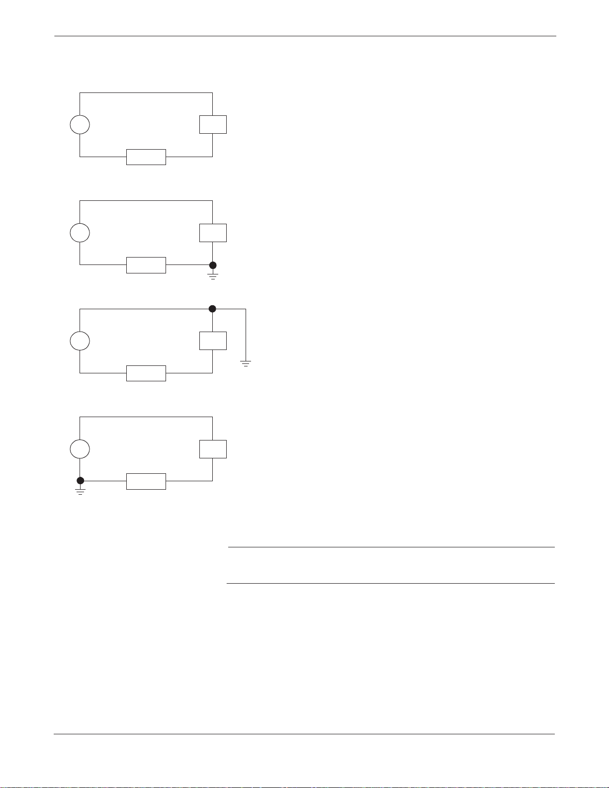
FIGURE 2-8. T ypic al Ef fe ct s of Groundi ng
on Accuracy for Fast Sample Computers
(4-20 mA loops only).
Installation
PT
PT
PT
LOAD
LOAD
LOAD
+
PS
–
+
PS
Ungrounded System
Impressed Voltage: 12 to 22 mVp-p
32 kHz
Effect: 0.01% of span.
Ground Between Negative Sid e of Power Sup ply an d Load
Impressed Voltage: 35 to 60 mVp-p
32 kHz
Effect: 0.03% of span.
–
+
PS
–
Ground Between Positive Sid e of Transmitter and Power Supply
Impressed Voltage: 35 to 60 mVp-p
32 kHz
Effect: 0.03% of span.
PT
LOAD
+
PS
–
Ground Between Negative Terminal of Transmitter and Load
Impressed Voltage: 500 to 600 mVp-p
32 kHz
Effect: 0.27% of span.
NOTE
Typical effects caused by the impressed voltage on a computer with a
sampling time of 100 microseconds using a 2 to 10 volt signal.
2-13
Page 22
Model 1151 Alphaline® Pressure Transmitters
LIQUID LEVEL
MEASUREMENT
Open Vessels
Closed Vessels
Differential pressure transmitters used for liquid level applications
measure hydrostatic pressure head. Liquid level and specific gravity of
a liquid are factors in determining pressure head. This pressure is
equal to the liquid height above the tap multiplied by the specific
gravity of the liquid. Pressure head is independent of volume or vessel
shape.
A pressure transmitter mounted near a tank bottom measures the
pressure of the liquid above.
Make a connection to the high pressure side of the transmitter, and
vent the low pressure side to the atmosphere. Pressure head e quals the
liquid’s specific gravity multiplied by the liquid height above the tap.
Zero range suppression is required if the transmitter lies below the zero
point of the desired level range. Figure 2-9 shows a liquid level
measurement example.
Pressure above a liquid affects the pressure measured at the bottom of
a closed vessel. The liquid specific gravity multiplied by the liquid
height plus the vessel pressure equals the pressure at the bottom of the
vessel.
To measure true level, the vessel pressure must be subtracted from the
vessel bottom pressure. T o do this, make a pressure tap at the top of the
vessel and connect this to the low side of the transmitter. Vessel
pressure is then equally applied to both the high and low sides of the
transmitter . The resulting diff eren tial pressure is pro portional to liquid
height multiplied by the liquid specific gravity.
Dry Leg Condition Low-side transmitter piping will remain empty if gas above the liquid
does not condense. This is a dry leg condition. Range determination
calculations are the same as those described for bottom-mounted
transmitters in open vessels, as shown in Figure 2-9.
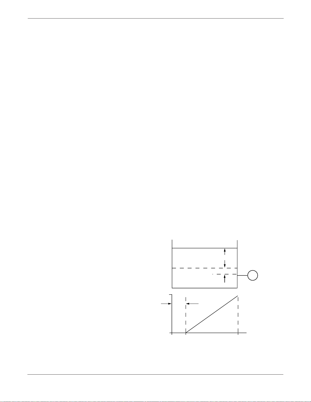
FIGURE 2-9. Liquid Level
Measurement Example.
X
Let X equal the vertical distance between the minimum and maximum
measurable levels (500 in.).
Let Y equal the vertical distance between the transmitter datum line and the
minimum measurable level (100 in.).
Let SG equal the specific gravity of the fluid (0.9).
Let h equal the maximum head pressure to be measured in inches of water.
Let e equal head pressure produced by Y expressed in inches of water.
Let Range equal e to e + h.
Then h = (X)(SG)
= 500 x 0.9
= 450 inH
e=(Y)(SG)
= 100 x 0.9
= 90 inH
Range = 90 to 540 inH
O
2
O
2
O
2
20
mA dc
ZERO
4
SUPPRESION
900
inH2O
Y
T
540
2024-0171A, 0172A
2-14
Page 23
Installation
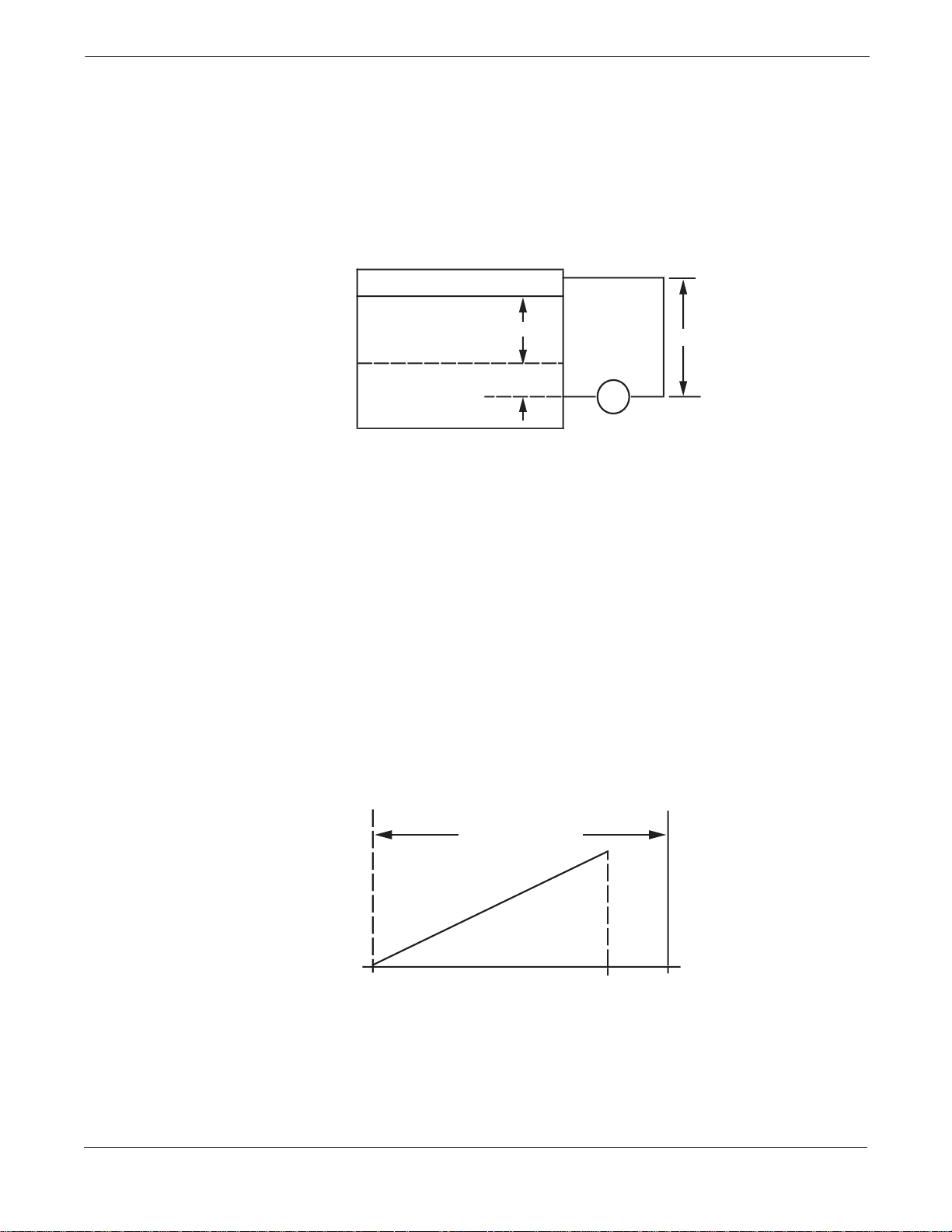
Wet Leg Condition Condensation of the gas above the liquid slowly causes the low side of
the transmitter piping to fill with liquid. The pipe is purposely filled
with a convenient reference fluid to eliminate this potential error. This
is a wet leg condition.
The reference fluid will exert a head pressure on the low side of the
transmitter . Z ero elevatio n of the range must then be made. See Figure
2-10.
FIGURE 2-10. Wet Leg Example.
X
Y
LT
Z
H L
Let X equal the vertical distance betwe en the minimum and max im um
measurable levels (500 in.).
Let Y equal the vertical distance between the transmitter datum line and the
minimum measurable level (50 in.).
Let z equal the vertical distance between the top of the liquid in the wet leg
and the transmitter datum line (600 in.).
Let SG
equal the specific gravity of the fluid (1.0).
1
Let SG
equal the specific gravity of the fluid in the wet leg (1.1).
2
Let h equal the maximum head pressure to be measured in inches of water.
Let e equal the head pressure produced by Y expressed in inches of water.
Let s equal head pressure produced by z expressed in inches of water.
Let Range equal e – s to h + e – s.
Then h = (X)(SG
= 500 x 1.0
= 500 in H
e=(Y)(SG
= 50 x 1.0
= 50 inH
s=(z)(SG
= 600 x 1.1
= 660 inH
Range = e – s to h + e – s.
= 50 – 660 to 500 + 50 – 660
= –610 to –110 inH
)
1
O
2
)
1
O
2
)
2
0
2
0
2
ZERO ELEVATION
inH2O
20
mA dc
4
-110-610
0
2024-0167A 2024-0168A
2-15
Page 24
Model 1151 Alphaline® Pressure Transmitters
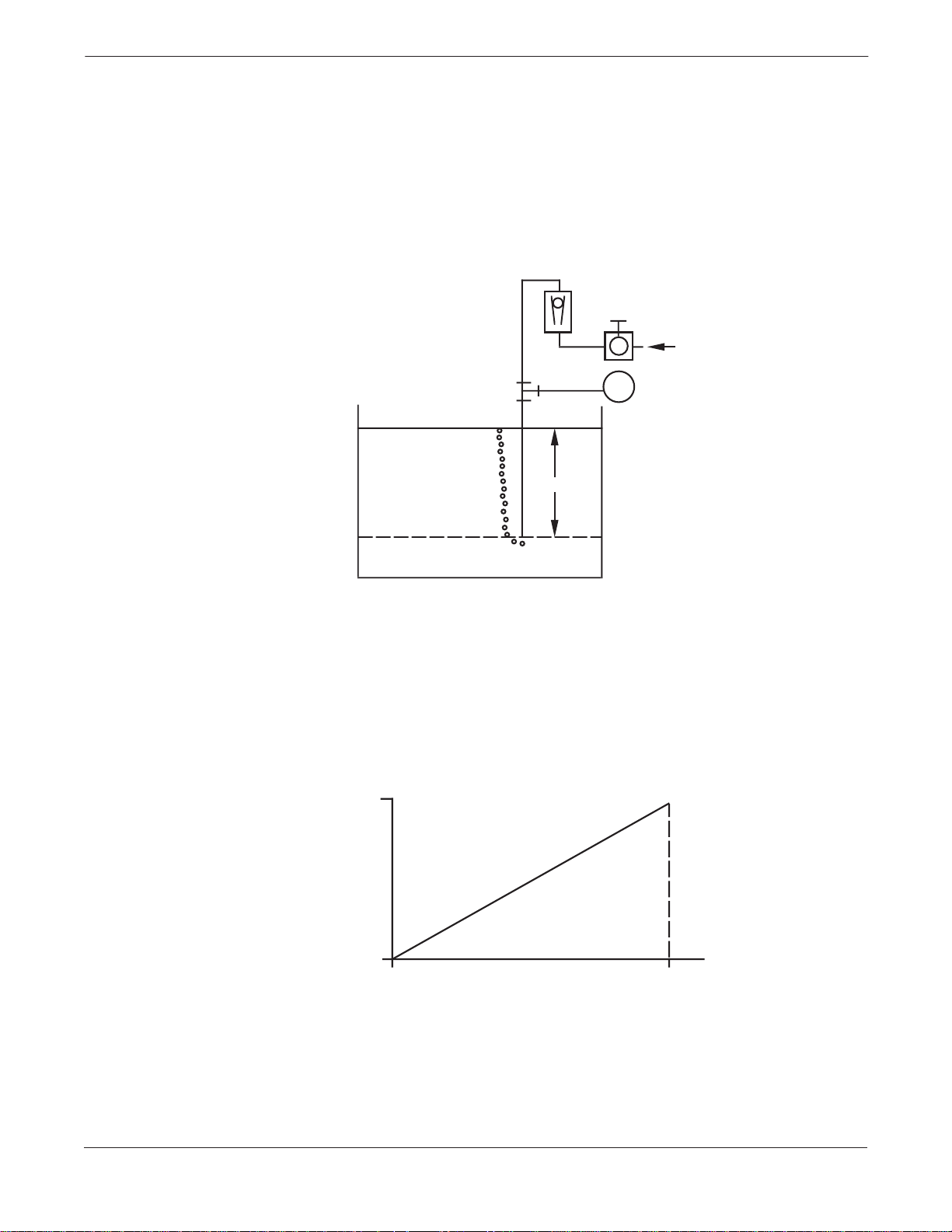
Bubbler System in Open Vessel A bubbler system that has a top-mounted pressure transmitter can be
used in open vessels. This system consists of an air supply, pressure
regulator, constant flow meter, pressure transmitter, and a tube that
extends down into the vessel.
Bubble air through the tube at a constant flow rate. The pressure
required to maintain flow equals the liquid’s specific gravity multiplied
by the vertical height of the liquid above the tube opening. Figure 2-11
shows a bubbler liquid level measurement example.
FIGURE 2-11. Bubbler Liquid Level
Measurement Example.
AIR
T
X
Let X equal the vertical distance betwe en the minimum and max im um
measurable levels (100 in.).
Let SG equal the specific gravity of the fluid (1.1).
Let h equal the maximum head pressure to be measured in inches of water.
Let Range equal zero to h.
Then h = (X)(SG)
= 100 x 1.1
= 110 inH
Range = 0 to 110 inH
20
mA dc
4
0
O
2
O
2
110
inH2O
2024-0165A
2024-0166A
2-16
Page 25
Section
3 Calibration
Calibration of the Rosemount Model 1151 Pressure Transmitter is
simplified by its compact and explosion-proof design, external span and
zero adjustments, separate compartments for electronics and wiring,
and weatherproof construction. Descriptions of span, linearity, zero
adjustments, and damping follow.
Explosions can cause death or serious injury. Both
transmitter covers must be fully engaged to meet explosionproof requirements.
When replacing housing covers, tighten the covers enough
to make contact with the O-ring seals. If the covers are not
tightened enough, moisture can enter the housing and
cause transmitter failure.
QUICK CALIBRATION
PROCEDURE (FOR E, G,
AND J ELECTRONICS)
QUICK CALIBRATION
PROCEDURE (FOR L AND
M ELECTRONICS)
The following Quick Calibration Procedures are for those users who are
already familiar with the analog Model 1151.
NOTE
The zero and span adjustments are interactive. For applications
requiring large elevated or suppressed values, refer to Elevated or
Suppressed Zeros on page 3-7.
1. Apply 4 mA-point pressure and turn zero screw to output 4 mA.
2. Apply 20 mA-point pressure.
3. Subtract actual output from desired output.
4. Divide difference by 3.
5. Turn span screw above or below desired output by value in Step 4.
6. Repeat Steps 1 through 5 until calibrated.
1. Apply 1 V dc-point pressure for M electronics (0.8 V dc for L electronics)
and turn zero screw to output 1 V dc (0.8 V dc for L electronics).
2. Apply 5 V dc-point pressure (M electronics) or 3.2 V dc (L electronics).
3. Subtract actual output from desired output.
4. Divide difference by 3.
5. Turn span screw above or below desired output by value in Step 4.
6. Repeat Steps 1 through 5 until calibrated.
3-1
Page 26

Model 1151 Alphaline® Pressure Transmitters
Example for a Model 1151DP Range 4: For a desired calibration of 0
to 100 inH
1. Adjust the zero. With zero input applied to the transmitter, turn
the zero adjustment screw until the transmitter reads 4 mA.
2. Adjust the span. Apply 100 inH
connection. Turn the span adjustment screw until the transmitter
output reads approximately 20 mA.
3. Release the input pressure and readjust the zero output to read 4
mA ±0.032 mA.
4. Re-apply 100 inH
greater than 20 mA, divide the difference by 3, and subtract the
result from 20 mA. Adjust the 100% output to this value.
If the output reading is less than 20 mA, divide the difference by 3 and
add the result to 20 mA. Adjust the 100% output to this value.
Example: The full scale transmitter output is 20.100 mA. Dividing
0.100 by 3.0 gives the product 0.033. Subtracting the product 0.033
from 20.00 mA gives the difference 19.967 mA. Adjust the 100% output
to this value.
5. Release input pressure and readjust the zero.
6. Apply 100% input and repeat Steps 3 through 5 if the full scale
output is not 20 ±0.032 mA.
O, use the following procedure:
2
O to the transmitter high side
2
O to the transmitter. If the output reading is
2
NOTE
Under operating conditions that subject the transmitter to temperature
extremes or significant vibration, mechanical backlash may occur in the
zero and span adjustment screws. To improve the stability of zero and
span settings in these circumstances, back off the adjustment screws
slightly after final adjustment to break contact between the
potentiometer blades and the adjustment screw slot surfaces.
3-2
Page 27
Calibration
DATA FLOW WITH
CALIBRATION OPTIONS
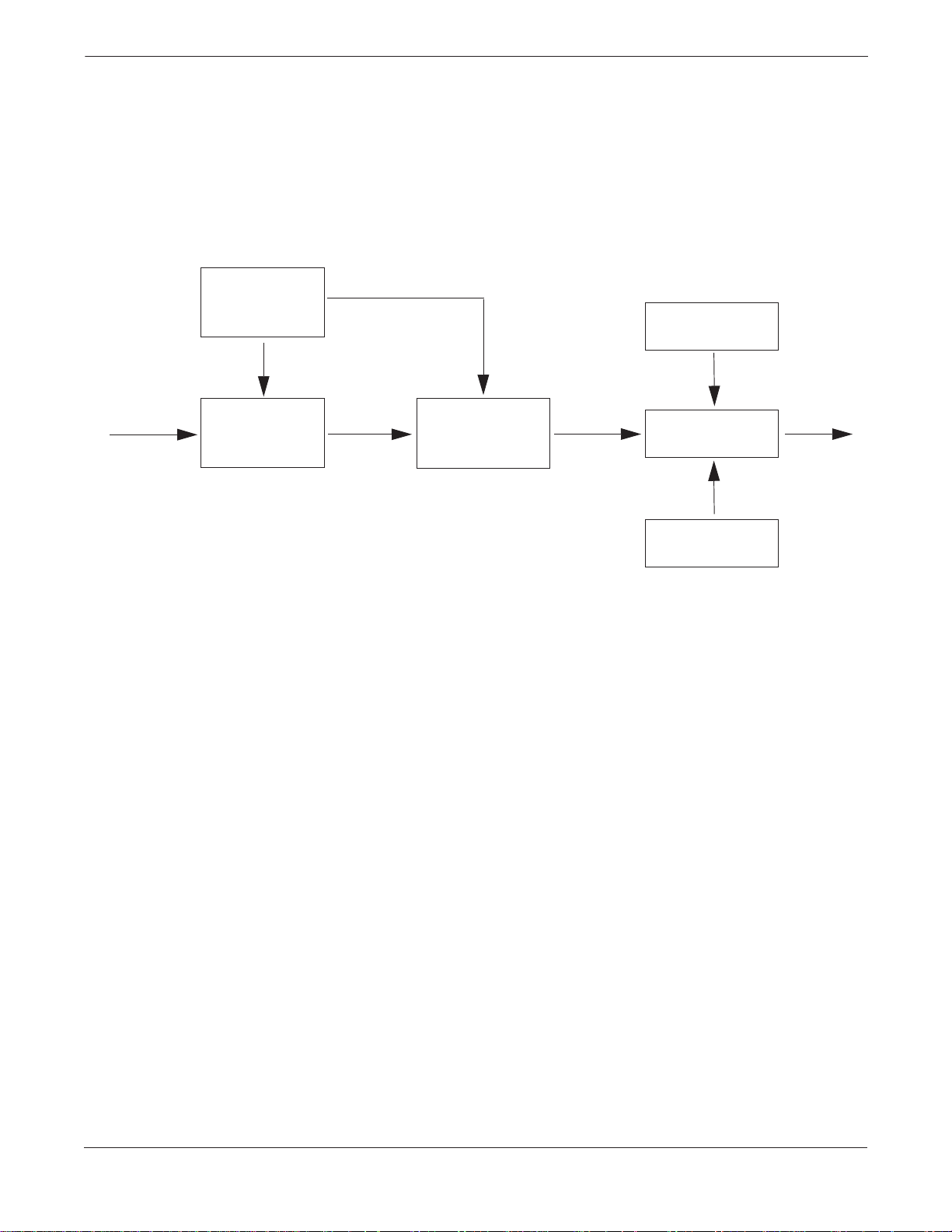
FIGURE 3-1. Model 1151 Transmitter
Data Flow with Calibration Options.
Sensor
Excitation
➀ Pressure
➁
Sensor
Figure 3-1 illustrates the Model 1151 Transmitter data flow with
calibration tasks.
Zero
Adjustment
➂
Signal
Conditioning
➃
Output
Span
Adjustment
Output
This data flow can be summarized in four major steps:
1. Pressure is applied to the sensor.
2. A change in pressure is measured by a change in the sensor
output.
3. The sensor signal is conditioned for various parameters.
4. The conditioned signal is converted to an appropriate analog
output.
3-3
Page 28
Model 1151 Alphaline® Pressure Transmitters
SPAN ADJUSTMENT
RANGE
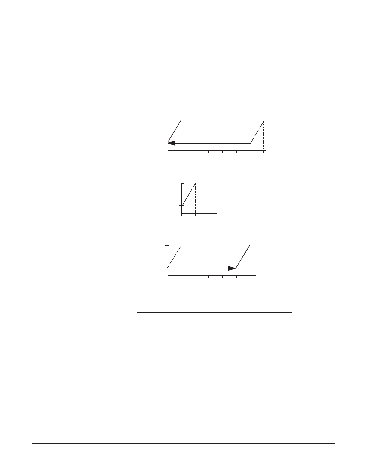
ZERO ADJUSTMENT
RANGE
FIGURE 3-2. Zero Adjustment Range.
The span on a Model 1151 with E, G, and J output options is
continuously adjustable to allow calibration anywhere between
maximum span and one-sixth of maximum span. For example, the span
on a Range 4 transmitter can be adjusted between 25 and 150 inH
O
2
(6.2 and 37.2 kPa).
The zero on a Model 1151 with the E or G output options can be
adjusted for up to 500% suppression or 600% elevation. See Figure 3-2.
Output
(mA)
20
Pressure
O)
(inH
2
–150 –125 –100
Output
(mA)
20
Output
(mA)
600% Zero Elevation
–75
–50 –25 0
600% Zero Elevation*
20
4
0 25
No Zero Elevation or Suppression*
Pressure
O)
(inH
2
4
25
500% Zero Elevation
4
25
0
*Graphs based on a range 4 (0-25 inH2O to 0-150 inH2O) 1151
with a calibrated span of 25 inH
50
500% Zero Suppression*
75
100
O.
2
125
150
1151-0193A
The zero may be elevated or suppressed to these extremes with the
limitation that no pressure within the calibrated range exceeds the fullrange pressure limit. For example, a Range 4 tr ansmitt er cannot be
calibrated for 1 00 to 200 i nH
suppression) because 200 inH
O (24.8 to 49.7 kPa) (only 100% zero
2
O exceeds the 150 inH2O full-range
2
pressure limit of a Range 4.
To make large elevation or suppression adjustments, it is necessary to
move the jumper on the component side of the amplifier board. Figure
3-3 on page 3-5 shows elevation and suppression jumper settings. The
jumper has three positions. The middle position allows normal levels of
elevation or suppression. For larger adjustm ents, move the jumper to
the ELEVATE ZERO (EZ) or SUPPRESS ZERO (SZ) as marked.
3-4
Page 29
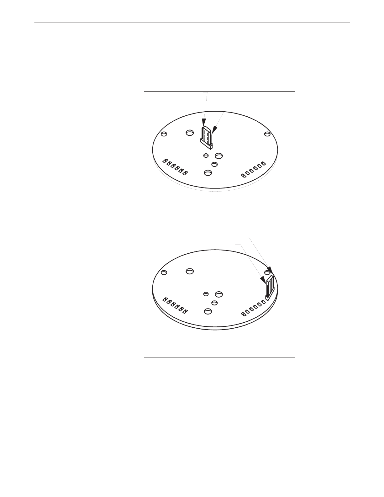
FIGURE 3-3. Elevation and
Suppression Jumper Settings.
Calibration
NOTE
Always make sure that the jumper is fully seated on its pins. If the
jumper has not been placed in any of the three positions, the amplifier
board will provide normal levels of elevation or suppression. A slide
switch replaces the jumper pin on some versions of the amplifier board.
E Output Option
(4–20 mA)
Elevate Zero
Suppress Zero
G Output Option
(10–50 mA)
Suppress Zero
Elevate Zero
NOTE: The jumper is located on the co mpon en t sid e of the
amplifier board. Jumper positions may vary from those shown. The
board must be unplugged from the transmitter to gain acce ss to
the component.
1151-0194A
3-5
Page 30

Model 1151 Alphaline® Pressure Transmitters
ZERO AND SPAN
ADJUSTMENT
FIGURE 3-4. Zero and Span
Adjustment Screws.
The zero and span adjustment screws are accessible externally
behind the nameplate on the terminal side of th e electronics
housing. See Figure 3-4. The output of the transm itter increases
with clockwise rotation of the adjustment screws. The zero
adjustment screw and ELEVATE ZERO/SUPPRESS ZERO jumper
do not affect the span. Span adjustment, however, does affect zero.
This effect is minimized with zero-based span s. Therefore, w hen
calibrations having elevated or suppressed zeros are made, it is
easier to make a zero-based calibration and achieve the required
elevation or suppression by adjusting the zero adjustment screw
(and ELEVATE ZERO/SUPPRESS ZERO jumper as required).
A degree of mechanical backlash is present in the zero and span
adjustments, so there will be a dead band when the direction of
adjustment is changed. Because of the backlash, the simplest procedure
is to purposely overshoot a larger amount before reversing the direc tion
of the adjustment.
Zero
Screw
Span
Screw
1151-1151A25A
3-6
Page 31

Calibration
ELEVATED OR
SUPPRESSED ZEROS
Non-zero-based calibrations are termed as having “elevated” or
“suppressed” zeros. Calibrations that have a lower calibrated value
below zero are termed elevated. Compound ranges are included in this
category. Calibrations that have a lower calibrated value above zero are
termed suppressed.
The easiest way to calibrate transmitters with elevated or suppressed
zeros is to perform a zero-based calibration and then elevate or
suppress the zero by adjusting the zero adjustment screw.
Model 1151DP Range 4 Suppression Example: For a desired
calibration of 20 to 120 inH
1. Calibrate the transmitter to 0 to 100 inH
O (4.9 to 29.8 kPa), proceed as follows:
2
O (0 to 24.8 kPa) as
2
described in the zero and span adjustment information.
2. Apply 20 inH
O (4.9 kPa) to the high side proce ss conne ction, and
2
adjust the zero until the transmitter output reads 4 mA.
Do not use the span adjustment.
Model 1151DP Range 4 Elevation Example: For a calibration
of –120 to –20 inH
1. Calibrate the transmitter to 0 to 100 inH
O (–29.8 to –4.9 kPa), proceed as follows:
2
O (0 to 24.8 kPa) as
2
described in the zero and span adjustment information.
2. Apply 120 inH
O (29.8 kPa) to the low side process connection,
2
and adjust the zero until the transmitter output reads 4 mA.
Do not use the span adjustment.
LINEARITY ADJUSTMENT
NOTE
For large amounts of elevation or suppression, it may be necessary to
reposition the ELEVATE/SUPPRESS ZERO jumper. To do this, remove
the amplifier board, and move the jumper to the ELEVATE or
SUPPRESS position as required. See Figure 3-3 on page 3-5.
In addition to the span and zero adjustments, a linearity adjustment
screw (marked LIN) is located on the solder side of the amplifier board.
See Figure 3-5. This is a factory calibration adjusted for optimum
performance over the calibrated range of the instrument and normally
is not readjusted in the field. The user may, however, maximize
linearity over a particular range using the following procedure:
1. Apply mid-range pressure and note the error between the
theoretical and actual output signal.
2. Apply full-scale pressure. Multiply the error noted in Step 1 by
six and then that product by the Range Down Factor, which is
calculated as shown below:
Range Down Factor
Maximum Allowable Span
=
------------------------------------------------------------------------ -
Calibrated Span
Add this result to the full-scale output (for negative errors), or subtract
the result from the full-scale output (for positive errors) by turning the
linearity adjustment screw.
3-7
Page 32

Model 1151 Alphaline® Pressure Transmitters
Example: At 4 to 1 Range Down Factor, the mid-scale point is low by
0.05 mA. Therefore, turn the linearity adjustment screw until full-scale
output increases by (0.05 mA 3 6 3 4) = 1.2 mA.
3. Readjust the zero and span.
FIGURE 3-5. Damping and Linearity
Adjustment Screws.
Adjustment
Adjustment
Access to linearity and damping adjustments is gained by
removing cover on circuit board side.
Location of linearity adjustment screws may vary slightly between
output codes.
Damping
Screw
Linearity
Screw
1151-0196B
DAMPING ADJUSTMENT
The amplifier boards for output options E, G, and J are designed to
permit damping of rapid pulsations in the pressure source through
adjustment of the damping screw shown in Figure 3-5 on page 3-8. The
adjustment is marked DAMP on the solder side of the amplifier board.
The settings available provide time constant values between 0.2 and
1.66 seconds. The instrument is calibrated and shipped with this
control set at the counterclockwise stop (0.2 second time constant). It is
recommended that the shortest possible time constant setting be
selected. Since the transmitter calibration is not influenced by the time
constant setting, the damping may be adjusted with the transmitter
connected to the process. Turn the damping control clockwise until the
desired damping is obtained.
The adjustment screw has positive stops at both ends.
Forcing it beyond the stops m ay cause permanent damage.
3-8
Page 33

Calibration
STATIC PRESSURE SPAN
CORRECTION FACTOR
TABLE 3-1. Model 1151 DP/HP Span
Shift.
High static pressure causes a systematic span shift in the transmitter.
It is linear and easily correctable during calibration. Table 3-1 shows
the amount of span shift for range codes 3 through 8.
:
Range
Code
3
4
5
6
7
8
Span Shift % Input Per 1,000 psi
316L SST Hastelloy Monel
–1.75%
–0.87%
–0.81%
–1.45%
–1.05%
–0.55%
–1.00%
–0.60%
–0.70%
–1.45%
–1.05%
–0.55%
–1.00%
–0.50%
–0.75%
–1.45%
–1.05%
–0.55%
The following examples illustrate a compensation method of accounting
for the span shift. For more complicated calibration conditions, refer to
Rosemount Report D8500141 or contact Customer Central at 1-800999-9307.
Example 1 - Refer to Table 3-1: One method is to adjust the input
and allow the transmitter output to remain at 20 mA. Use the following
formula:
Corrected Input
= Desired URV + [(S 3 URV) 3 (P/1000)],
Where S = Value from Table 3-1, divided by 100.
To calibrate a Range 4 transmitter 0 to 150 inH
O (0 to 37.2 kPa) and
2
correct for 1,500 psi static line pressure, use the following correction:
Corrected Input
= 150 + [(–0.0087 3 150) 3 (1500/1000)]
= 148.04 inches
With 148.04 inches applied as input at atmospheric pressure, set the
transmitter to 20 mA. When the transmitter is exposed to 1,500 psi
static line pressure, output will be 20 mA at 150 inches input.
Where computers or microprocessor receivers are used, the
mathematical definitions used in the preceding tables can be used to
automatically and continuously make the correction.
All transmitters should be rezeroed under line pressure to remove zero
3-9
Page 34

Model 1151 Alphaline® Pressure Transmitters
error.
Example 2 - Refer to Table 3-2: A Model 1151DP Range 4 with a 4 –20
mA output operating at 1,200 psi static pressure requires the output at
100% to be corrected to 20.168 mA. Therefore, the transmitter should
be adjusted from 4–20.168 mA during calibration. After installation,
and with both process inputs pressurized to 1,200 psi, readjust the zero
to 4.000 mA to remove the small zero error.
TABLE 3-2. Model 1151DP Static
Pressure 4–20 mA Output Code E
Corrected Output Calibration at 100%
Input SST Isolators.
Static
Pressure (psi)
100
200
300
400
500
600
700
800
900
1000
1100
1200
1300
1400
1500
1600
1700
1800
1900
2000
Static
Pressure (kPa)
689
1379
2068
2758
3447
4137
4826
5516
6205
6895
7584
8274
8963
9653
10342
11032
11721
12411
13100
13790
Range 3 Range 4 Range 5
20.029
20.057
20.086
20.114
20.143
20.171
20.200
20.228
20.257
20.285
20.314
20.342
20.371
20.399
20.428
20.456
20.485
20.513
20.542
20.570
20.014
20.028
20.042
20.056
20.070
20.084
20.098
20.112
20.126
20.140
20.154
20.168
20.182
20.196
20.210
20.224
20.238
20.252
20.266
20.280
20.013
20.026
20.039
20.052
20.066
20.079
20.092
20.104
20.118
20.131
20.144
20.157
20.170
20.183
20.197
20.210
20.223
20.236
20.250
20.262
TABLE 3-3. Output Correction Facto rs
SST Isolators.
Example 3 - Refer to Table 3-3: The correction factor at 100% input
shift for a Range 5 transmitter with a 4–20 mA output operating at
1,500 psi static pressure would be:
S = 0.131 3 1.5 = 0.197 mA
Therefore, the calibration for this transmitter would be
from 4–20.197 mA.
Range
Code
3
4
5
6
7
8
E Output
4–20 mA
S = 0.285 P
S = 0.140 P
S = 0.131 P
S = 0.235 P
S = 0.170 P
S = 0.088 P
G Output
10–50 mA
S = 0.712 P
S = 0.350 P
S = 0.327 P
S = 0.588 P
S = 0.425 P
S = 0.220 P
NOTE
Correction factors apply to E and G outputs at 100% input (P = static
pressure in 1,000 psi).
3-10
Page 35

Section
4 Options
Model 1151 options can simplify installation and operation. This section
describes the following options:
• Mounting Brackets
• Analog and LCD Indicating Meters
• Terminal Blocks (Transient Protection and Filter)
MOUNTING BRACKETS
(OPTION CODES B1–B7 AND B9) Optional mounting brackets available with the Model 1151 allow
mounting to a 2-inch pipe or panel. Figure 4-1 shows bracket
dimensions and mounting configurations for the various bracket
options.
Pipe Mounting Brackets
Option Codes B1, B4, and B7 are sturdy, epoxy-polyester-painted
brackets designed for 2-inch pipe mounting. Option Code B1 is
constructed of carbon steel with carbon steel bolts. Option Code B4 is
the same bracket as Option Code B1, with 316 SST bolts. Option Code
B7 is also the same bracket as Option Code B1 with a 316 SST bracket
and 316 SST bolts.
Flat Mounting Brackets
Option Codes B3, B6, and B9 are flat brackets designed for 2-inch pipe
mounting. Option Code B3 is constructed of carbon steel with a carbon
steel U-bolt. Option Codes B6 and B9 are the same bracket
configuration as Option Code B3. Option Code B6 provides 316 SST
bolts and Option Code B9 provides a 316 SST bracket and 316 SST
bolts.
Panel Mounting Brackets
Option codes B2 and B5 are panel brackets designed for bolting to any
flat surface.
4-1
Page 36

Model 1151 Alphaline® Pressure Transmitters
FIGURE 4-1. Mounting Bracket
Options.
3.75
(95)
3.75 (95)
1.65 (42)
2.81
(71)
1.65 (42)
3.87
(98)
2.625 (67)
2.62
(67)
4.97
(127)
5.625
(143)
2.625
(67)
PIPE MOUNTING BRACKET OPTION CODES B1, B4, AND B7
3.87 (98)
Mounting Holes
0.375 Diameter
(10)
2.81 Typ.
(71)
1.40 (46)
2.81 Typ.
(71)
4.5 (114)
1.40
(36)
PANEL MOUNTING BRACKET OPTION CODES B2 AND B5
5.625
(143)
3051-3051D19A, 1151-1151D,B06C
2.81 Typ.
(71)
2.625
(67)
3051-3051B19A, 1151-0244A, 1151-1151E06A
2.125 (54)
1.62 (41)
NOTE
Dimensions are in inches (millimeters).
4-2
8 (203)
2.81 (71)
FLAT MOUNTING BRACKET OPTION CODES B3, B6, AND B9
3051-3051H19B, 1151-1151F06B
Page 37

Options
ANALOG METERS
(4–20 mA ONLY)
LCD METERS
(4–20 mA ONLY)
Option Codes M1–M3 and M6 provide local indication of the
transmitter output in a variety of scaling configurations with an
indicator accuracy of ±2 percent. The plug-in mounting configuration
allows for simple installation and removal of the analog meters. The
meter scaling options are shown below.
M1 Linear analog meter, 0-100% scale
M2 Square-root analog meter, 0-100% flow scale
M3 Special scaling analog meter, (specify range)
M6 Square-root analog meter, 0-10
Explosions can cause death or serious injury. To meet
hazardous location requirements, any transmitter with a tag
specifying Option Codes I5, I1, N1, I8, I7, or N7 requires an
intrinsically safe analog meter (Part No. 01151-0744-XXXX)
or an LCD Meter (Part No. 01151-1300-XXXX).
√ scale
The LCD meter options, M4 and M7–M9 provide a highly accurate local
display of the process variable. A variety of scaling configurations are
available and listed as follows:
M4 Linear LCD Meter, 0 to 100%, User Selectable
M7 Special scale LCD meter (specify range, mode, and
engineering units)
M8 Square-root LCD meter, 0 to 100%
M9 Square-root LCD meter, 0 to 10
√
LCD Meter Configuration
Explosions can cause death or serious injury. When adding
a meter option to a Model 1151 with an Option Code R1 or
R2 terminal block, make sure to change to cemented meter
covers with a glass window. Make sure a sticker is located
inside the cover that indicates a “cemented cover.” This
cover is required to maintain explosion-proof approval.
The Rosemount LCD meter plugs directly into the Model 1151 to
provide a highly accurate digital display of the process variable. The
following explains the configuration and assembly of the LCD meter
and includes the applicable functional, performance, and physical
specifications. This meter adds no voltage drop in the 4–20 mA current
loop when connected directly across the transmitter test terminals.
The LCD meter may be configured to meet specific requirements by
using the left and right calibration buttons located on the meter face as
shown in Figure 4-2. The analog bar graph is also shown in Figure 4-2.
The 20-segment bar graph is factory calibrated and represents
4–20 mA directly.
4-3
Page 38

Model 1151 Alphaline® Pressure Transmitters
FIGURE 4-2. LCD Meter.
Analog
Bar Graph
Left Configuration
Button
Right Configurati o n
Retaining
Ring
Button
No calibration equipment is required to configure the LCD meter, but
there must be a current (between 4 and 20 mA) flowing through the
loop. The actual value of the current is not significant. In addition,
meter configuration does not affect the transmitter/loop current. Use
the following meter configuration procedure to properly configure the
LCD meter.
Remove the Cover 1. Unscrew the retaining ring shown in Figure 4-2 and lift the
transparent cover off of the housing.
NOTE
The LCD meter time-out is approximately 16 seconds. If keys are not
pressed within this period, the indicator reverts to reading the current
signal.
Position the Decimal Point and
Select the Meter Function
2. Press the left and right configuration buttons simultaneously and
release them immediately.
3. To move the decimal point to the desired location, press the left
configuration button. Note that the decimal point wraps around.
4. To scroll through the mode options, press the right configuration
button repeatedly until the desired mode is displayed. See Table 4-1.
LCD-001AB
TABLE 4-1. LCD Meter Modes.
4-4
Options Relationship between Input Signal and Digital Display
L in
L inF
Srt
SrtF
Square root function only relates to the digital display.
The bar graph output remains linear with the current signal.
Square root response
The digital display will be proportional to the square root of the input current where 4 mA=0
and 20 mA=1.0, scaled per the calibration procedure. The transition point from linear to
square root is at 25% of full scale flow.
Filter response operates upon “present input” and “input received in the previous five second
interval” in the following manner:
Display = (0.75 3 previous input) + (0.25 3 present input)
This relationship is maintained provided that the previous reading minus the present reading is
less than 25% of full scale.
Linear
Linear with five-second filter
Square root
Square root with five-second filter
Page 39

Options
Store the Information 5. Press both configuration buttons simultaneously for two seconds.
Note that the meter displays “----” for approximately 7.5 seconds
while the information is being stored.
Set the Display Equivalent
to a 4 mA Signal
6. Press the left button for two seconds.
7. To decrement the display numbers, press the left configuration
button and to increment the numbers, press the right
configuration button. Set the numbers between –999 and 1000.
8. To store the information, press both configuration buttons
simultaneously for two seconds.
Set the Display Equivalent
to a 20 mA Signal
9. Press the right button for two seconds.
10. To decrement the display numbers, press the left configuration
button on the display and to increment the numbers, press the
right configuration button. Set the numbers between –999 and
9999. The sum of the 4 mA point and the span must not exceed
9999.
11. To store the information, press both configuration buttons
simultaneously for two seconds. The LCD meter is now
configured.
Replace the Cover 12. Make sure the rubber gasket is seated properly, replace the
transparent cover, and replace the retaining ring.
LCD Meter Assembly
Figure 4-3 shows the mounting hardware required to properly install
the LCD meter on a transmitter or in the field signal indicator. This
mounting hardware may also be used with the Rosemount universal
(analog) meter.
FIGURE 4-3. LCD Meter
Exploded View.
Mounting Screw into Hou sin g
Mounting Screws into Meter
(6-32 x 5/6 in.)
Meter (Meter may be rotated
in 90 degree increments)
Cover Bushing
(6-32 x 1/4 in.)
Retaining Straps
Strap Washer
Mounting Screw
into Mounting
Plate
Terminal Screws
(Mount into Transmitter
“Test” Terminal Block)
Mounting Plate
Cover Foam Spacer
751-0264B
4-5
Page 40

Model 1151 Alphaline® Pressure Transmitters
LCD Meter Specifications
Input Signal
4–20 mA dc.
Meter Indication
4-digit LCD showing –999 to 9999. A 20-segment bar graph directly
represents the 4–20 mA current.
Scaling/Calibration
4 mA Point Limits: –999 to 1000.
Span limits: 0200 to 9999.
The sum of the 4 mA point and span must not exceed 9999.
Adjustments are made using non-interactive zero and span buttons.
Hazardous Locations Certifications
Approved for use with Model 1151.
Explosions can cause death or serious injury. When adding
a meter option to a Model 1151 with an Option Code R1 or
R2 terminal block, make sure to change to cemented meter
covers with a glass window. Make sure a sticker is located
inside the cover that indicates a “cemented cover.” This
cover is required to maintain explosion-proof approval.
Overload Limitation
666 mA.
Temperature Limits
Storage: –40 to 185 °F (–40 to 85 °C).
Operating: –4 to 158 °F (–20 to 70 °C).
Between temperatures –40 to –4 °F (–40 to –20 °C), the loop is intact
and the meter is not damaged.
Humidity Limitation
0 to 95% non-condensing relative humidity.
Update Period
750 ms.
Response Time
Responds to changes in input within a maximum of two update periods.
If the filter is activated, then the display responds to the change within
nine update periods.
Digital Display Resolution
0.05% of calibrated range ±1 digit.
Analog Bar Graph Resolution
5.0% of calibrated range.
Indication Accuracy
0.25% of calibrated range ±1 digit.
4-6
Page 41

Options
Stability
Over Time: 0.1% of calibrated range ±1 digit per 6 months.
Temperature Effect
0.01% of calibrated range per °C on zero.
0.02% of calibrated range per °C on span over the operating
temperature range.
Power Interrupt
All calibration constants are stored in EEPROM memory and are not
affected by power loss.
Failure Mode
LCD meter failure will not affect transmitter operation.
Under/Over Range Indication
Input current < 3.5 mA: Display blank.
Input current > 22.0 mA: Display flashes 112.5% of full scale value or
9999, whichever is less.
Meter Size
2¼-inch diameter face with ½-inch high characters.
TERMINAL BLOCKS
FIGURE 4-4. Terminal Blocks.
The terminal block options can increase the Model 1151 (output code
“E” only) Pressure Transmitter’s ability to withstand electrical
transients induced by lightning, welding, heavy electrical equipment,
or switch gears. The Model 1151, with the integral transient protection
option, meets the standard performance specifications as outlined in
this product manual. In addition, the transient protection circuitry
meets IEEE Standard 587, Category B and IEEE Standard 472, Surge
Withstand Capability.
NOTE
For a transient protection terminal block, specify Option Code R1 or R9.
Filter Terminal
Block (Code R2)
Transient
Protection and
Filter Terminal
Block (Code R1)
Retrofitable
Terminal Block
(Code R9)
1151-040AB
4-7
Page 42

Model 1151 Alphaline® Pressure Transmitters
Filter Terminal Block
(Option Code R2)
Transient Protection and
Filter Terminal Block
(Option Code R1)
Retrofitable Transient
Terminal Block
(Option Code R9)
R9 Terminal Block Installation Use a phillips and a flat-blade screwdriver and the following steps to
Option Code R2 provides enhanced performance in extremely harsh
EMI and RFI environments. This option cannot be retrofitted.
Option Code R1 provides EMI/RFI protection and the benefit of integral
transient protection. (This terminal block can be ordered as a spare
part to retrofit existing Model 1151 Transmitt ers with Option Code R2.)
NOTE
Options R1 and R2 do not require the use of shielded cable in most
electrically noisy environments.
The retrofitable transient protection terminal block (Option Code R9)
protects any Rosemount Model 1151 Analog Pressure Transmitter
(E electronics only without the R1 or R2 option). The terminal block
module installs directly into a transmitter providing highly reliable
transient protection. Included with the Retrofitable Transient
Protection Terminal Block is a hardware kit containing two short
mounting screws with two lock washers, one long grounding screw with
a square washer, and one label indicating an option has been installed.
If any parts of the hardware kit are missing, contact Rosemount North
American Response Center at 1-800-THE-RSMT (1-800-654-7768).
install the Retrofitable Transient Protection Terminal Block:
1. Turn off all power to the Model 1151 on which the terminal block
is being installed.
Explosion can cause death or serious injury. Do not remove
the instrument cover in explosive atmospheres when the
circuit is alive.
2. Unscrew the transmitter terminal-side (indicated on the housing
nameplate) cover (on the high side of the transmitter) exposing
the standard terminal block.
3. Disconnect wiring to the terminal block.
4. Remove the single grounding screw and the two signal terminal
screws, with terminal eyelet washers, from the standard terminal
block.
5. Set the Retrofitable Transient Protection Terminal Block into the
housing, making sure the ground and signal terminals are
properly aligned. See Figure 4-5 on page 4-9.
6. Insert the two short mounting screws with washers in the
mounting holes and tighten the terminal block to the transmitter .
See Figure 4-5 on page 4-9.
7. Turn the transient protector grounding sleeve, located in the
grounding hole, just enough to stabilize the unit on the
transmitter. See Figure 4-5 on page 4-9. Over tightening the
grounding sleeve will shift the terminal block out of alignment.
4-8
Page 43

FIGURE 4-5. Terminal Block
Exploded View (Option Code R9).
Options
Signal Terminal Screw s
Ground Sleeve
Ground Screw
Mounting Screws
Installed Option Label
1151-1085A01A
8. Insert the long grounding screw with the square washer into the
grounding hole and tighten.
9. Connect the positive power supply wire to the transient protector
terminal screw labeled “+ SIGNAL”, and the negative power
supply wire to the terminal screw labeled “- SIGNAL.”
10. Attach the supplied label to the terminal side transmitter cover
as shown in Figure 4-5.
Explosions can cause death or serious injury. Both
transmitter covers must be fully engaged to meet explosionproof requirements.
11. Replace the terminal side cover on the transmitter.
4-9
Page 44

Model 1151 Alphaline® Pressure Transmitters
Terminal Block
Specifications
(for R1, R2, and R9)
Hazardous Locations Certifications
(1)
Approved for use with I5, K5, I6, C6, E6, E8, I8
, I1
(1)(2)
, N1, E7, I7,
and N7 approved transmitters.
Materials of Construction
Noryl plastic.
Loop Resistance
6 V.
Transi ent Protection Limits (for R1 and R9)
IEEE 587 Category B
6 kV Crest (1.2 3 50 µs).
3 kV Crest (8 3 20 µs).
6 kV (0.5 µs at 100 kHz).
IEEE 472
SWC 2.5 kV Crest,
1 MHz waveform.
Accuracy Specification
Same as specified electronics accuracy when transmitter is calibrated
with installed Retrofitable Transient Protection Terminal Block.
(1) When the transient version of the filter module is used in an intrinsically safe installation,
supply transmitter from a galvanically isolated barrier.
(2) I1 and R1/R9 are not compatible.
4-10
Page 45

Section
5 Maintenance and
Troubleshooting
This section describes a variety of troubleshooting options associated
with the Model 1151 Alphaline
following sections.
Hardware Maintenance
• Hardware Diagnostics
• Transmitter Disassembly
• Sensor Module Checkout
• Transmitter Reassembly
• Optional Plug-in Meters
• Return of Material
Contact Customer Central at 1-800-999-9307 for further technical
support and the North American Response Center at 1-800-654-7768
for equipment service assistance.
Use only the procedures and new parts specifically
referenced in this manual. Unauthorized procedures or
parts can affect product performance and the output signal
used to control a process, and may render the instrument
dangerous. Direct any questions concerning these
procedures or parts to Rosemount Inc.
®
transmitter and is divided into the
HARDWARE
DIAGNOSTICS
If you suspect a malfunction, see Table 5-1 on page 5-2 to verify that
transmitter hardware and process connections are in good working
order. Under each of the five major symptoms, you will find specific
suggestions for solving the problem. Always deal with the most likely
and easiest to check conditions first.
Isolate a failed transmitter from its pressure source as soon
as possible. Pressure that may be present could cause
death or serious injury to personnel if the transmitter is
disassembled or ruptures under pressure.
5-1
Page 46

Model 1151 Alphaline® Pressure Transmitters
TABLE 5-1. Troubleshooting
Symptoms and Corrective Action.
Symptom Potential Source Corrective Action
High Output Primary Element
Impulse Piping
Power Supply Check the power supply output voltage at the transmitter.
Transmitter electronics Make su re that pos t conn ec to rs are clean.
Sensing Element The sensing element is not field repairable and must be replaced if found to be
Erratic Output Loop Wiring Check for adequate voltage to the transmitter.
Check for restrictions at primary element.
Check for leaks or blockage.
Ensure that blocking valves are fully open.
Check for entrappe d gas in l iquid lines and for liquid in dry lines.
Ensure that the density of fluid in impulse lines in unchanged.
Check for sediment in transmitter process flanges.
If the electronics are stil l susp ec t, subs titute new electronics.
defective. See “Transmitter Disasse mbly ” lat er in this section for instructions on
disassembly. Check for obvious defects , suc h as punct ure d isolat ing diaphragm or
fill fluid loss, and contact Rosemount North Ame rica n Resp o ns e Cent er at
1-800-THE-RSMT (1-800-654-7768).
Check for intermittent shorts, open circuits and multiple grounds.
Do not use higher than the specified voltage to check the
loop, or damage to the transmitter electronics may result.
Process Pulsation Adjust Damping
Transmitter Electronics Make sure the post con nect ors a re cl ean.
Impulse Piping Check for entrappe d gas in l iquid lines and for liquid in dry lines.
If the electronics are stil l susp ec t, subs titute new electronics.
5-2
Page 47

Maintenance and Troubleshooting
TABLE 5-1. (continued).
Symptom Potential Source Corrective Action
Low Output or No Output Primary Element Check the insulation and condition of primary element.
Loop Wiring Check for adequate voltage to the transmitter.
Impulse Piping Ensure that the pressure co nne ctio n is correct.
Sensing Element The sensing element is not field repairable and must be replaced if found to be
Transmitter Does Not Calibrate
Properly
Pressure Source/Correction Check for restrictions or leaks.
Meter Determine if the meter is functioning properly.
Power Supply Check the power supply output voltage at transmitter.
Transmitter Electronics Make sure the post con nect ors a re cl ean.
Sensing Element The sensing element is not field repairable and must be replaced if found to be
Note any changes in process fluid properties that may affect output.
Check the milliamp rating of the power supply against the total cur ren t being drawn
for all transmitters being powered.
Check for shorts and multiple gro u nds.
Check for proper polarity at the signal terminal.
Check loop impedance.
Check whether the transmit ter is in multidrop mod e, thus lock ing the outp u t at 4 mA.
Do not use higher than the specified voltage to check the loop,
or damage to the transmitter electronics may result
Check wire insulation to detect p oss ible shorts to ground.
Check for leaks or blockage.
Check for entrappe d gas in l iquid lines.
Check for sediment in the transmitter process flange.
Ensure that blocking valves are fully open and tha t bypa ss valve s are tightly clo sed .
Ensure that density of the fluid in the impulse piping is unchanged.
defective. See “Transmitter Disasse mbly ” lat er in this section for instructions on
disassembly. Check for obvious defects , suc h as punct ure d isolat ing diaphragm or
fill fluid loss, and contact Rosemount North Ame rica n Resp o ns e Cent er at
1-800-THE-RSMT (1-800-654-7768).
Check for proper leveling or zeroing of the pressure source.
Check weights/gauge to ensure proper pressure setting.
Determine if the pressure sourc e has su fficient accuracy.
If electronics are still susp ect , subst itute with new electronics.
defective. See “Transmitter Disasse mbly ” lat er in this section for instructions on
disassembly. Check for obvious defects , suc h as punct ure d isolat ing diaphragm or
fill fluid loss, and contact Rosemount North Ame rica n Resp o ns e Cent er at
1-800-THE-RSMT (1-800-654-7768).
.
5-3
Page 48

Model 1151 Alphaline® Pressure Transmitters
TRANSMITTER
DISASSEMBLY
Read the following information carefully before you disassemble a
transmitter. General information concerning the process sensor body,
electrical housing, and a procedure for their separation follow. Figure
5-1 shows an exploded view of the transmitter.
The following performance limitations may inhibit efficient or
safe operation. Critical applications should have appropriate
diagnostic and backup systems in place.
Pressure transmitters contain an internal fill fluid. It is used
to transmit the process pressure through the isolating
diaphragms to the pressure sensing element. In rare cases,
oil leak paths in oil-filled pressure transmitters can be
created. Possible causes include: physical damage to the
isolator diaphragms, process fluid freezing, isolator
corrosion due to an incompatible process fluid, etc.
A transmitter with an oil fill fluid leak can continue to perform
normally for a period of time. Sustained oil loss will
eventually cause one or more of the operating parameters
to exceed published specifications while a small drift in
operating point output continues. Symptoms of advanced oil
loss and other unrelated problems include:
• Sustained drift rate in true zero and span or operating
point output or both
• Sluggish response to increasing or decreasing
pressure or both
• Limited output rate or very nonlinear output or both
• Change in output process noise
• Noticeable drift in operating point output
• Abrupt increase in drift rate of true zero or span or both
• Unstable output
• Output saturated high or low
5-4
Explosion can cause death or serious injury. Do not remove
the instrument cover in explosive atmospheres when the
circuit is alive.
Explosions can cause death or serious injury. Do not break
the housing seal in explosive environments. Breaking the
housing seal invalidates the explosion-proof housing rating.
Electrical connections are located in a compartment identified as
TERMINAL SIDE on the nameplate. The signal and test terminals are
accessible by unscrewing the cover on the terminal side. The terminals
to the housing must not be removed, or the housing seal between
compartments will be broken. (Not applicable to R1 and R2 Options.)
Page 49

Maintenance and Troubleshooting
Process Sensor Body
Removal
Be aware of the following guidelines:
• The transmitter should be removed from service before
disassembling the sensor body.
• Process flanges can be detached by removing the four large bolts.
Do not scratch, puncture, or depress the isolating
diaphragms. Damaging the isolating diaphragms can inhibit
transmitter performance.
• Isolating diaphragms may be cleaned with a soft rag, mild
cleaning solution, and clear water rinse.
Do not use chlorine or acid solutions to clean the
diaphragms. Damaging the isolating diaphragms can inhibit
transmitter performance.
• Flange adapters and process flanges may be rotated or reversed
for mounting convenience.
FIGURE 5-1. Diffe rential Pressure (DP)
Transmitter Exploded View.
Electronics
Electronics
Cover
Electronics
Housing
d-Cell Sensing
Module
Process
Flange
Blank Flange
for AP and GP
1151-1151B27A
5-5
Page 50

Model 1151 Alphaline® Pressure Transmitters
Removing the Sensor from the
Electrical Housing
FIGURE 5-2. Removal of Electronics.
1. Disconnect the power source from the transmitter.
2. Unscrew the cover on the terminal side of the transmitter.
3. Remove the screws and unplug the electronics; see Figure 5-2.
4. Loosen the lock nut.
5. Remove the standoffs.
Do not damage the isolating diaphragms when unscrewing
the sensor module. Damaging the isolating diaphragms can
inhibit transmitter performance.
6. Unscrew the sensing module from the electronics housing, being
careful not to damage the sensor leads. Carefully pull the header
assembly board through the hole. The threaded connection has a
sealing compound on it and must be broken loose.
The sensing module is a welded assembly and cannot be further
disassembled.
5-6
1151-029AB
Page 51

Maintenance and Troubleshooting
Sensor Module Checkout The sensor module is not field repairable and must be replaced if found
to be defective. If no obvious defect is observed (such as a punctured
isolating diaphragm or fill fluid loss), the sensor module can be checked
as follows.
1. Carefully pull the header assembly board off of the post
connectors. Rotate the board 180 degrees about the axis formed
by the connecting leads. The sensor module and electronics
housing can remain attached for checkout.
NOTE
Do not touch the transmitter housing when checking resistances, or a
faulty reading can result.
2. Check the resistance between the sensor module housing and
pins one through four. This checks the resistance between both
capacitor plates and the sensing diaphragm, which is grounded to
the housing. This resistance should be greater than 10 MV.
3. Check the resistance between pin eight and the sensor module to
ensure that the module is grounded. Resistance should be zero.
NOTE
The above procedure does not completely test the sensor module. If
circuit board replacement does not correct the abnormal condition, and
no other problems are obvious, replace the sensor module.
FIGURE 5-3. Header Board
Connections .
.
7
8
9
10
11
12
(COMPONENT SIDE UP)
5
6
1
2
3
4
1151-0180B
5-7
Page 52

Model 1151 Alphaline® Pressure Transmitters
REASSEMBLY
PROCEDURE
Preliminary Precaution
Connecting the Electrical
Housing to the Sensor
Follow these procedures carefully to ensure proper reassembly.
Inspect all O-rings and replace if necessary. Lightly grease with silicone
oil to ensure a good seal. Use halocarbon grease for inert fill options.
Explosions can cause death or serious injury. Both
transmitter covers must be fully engaged to meet explosionproof requirements.
1. Insert the header assembly board through the electronics
housing.
2. Use a sealing compound (Locti te 222 - Small Screw Threadlocker)
on the threads of the sensor module to ensure a watertight seal on
the housing.
3. Screw the sensor module into the electrical housing making sure
that the threads are fully engaged. Be careful not to damage or
twist the sensor leads.
4. Align the sensor module with the high and low pressure sides
oriented for convenient installation.
5. Tighten the lock nut.
Backup Ring and O-ring
Installation
FIGURE 5-4. Detail Showing Process
O-ring and Backup Ring Installation of
Module Seal for Model 1151HP and GP
Range 9 (GP Range 0 Requires Only
One O-ring and Backup O-ring).
All HP transmitters and GP Range 9 and 0 transmitters require metal
backup rings to ensure O-ring integrity. Figure 5-4 on page 5-8
illustrates the position and orientation of the metal backup rings.
(Backup rings are not required on AP or DP transmitters or GP Range
3-8 transmitters.)
.
Process Flange
Metal Back-up Ring
O-ring
5-8
Flat Side (shiny side)
Toward O-ring
Beveled Side Toward Process Flange
1151-0983A01A
Page 53

Maintenance and Troubleshooting
NOTE
Handle the backup ring carefully, as it is fragile. Examine the ring
carefully. One side is beveled, while the other side is flat. The flat side
appears more shiny when viewed from above.
1. Clean the sealing surfaces carefully.
2. Place the module on a flat surface, “H” side up.
3. Place the greased flange O-ring around the isolator and push it
into the cavity.
Process leaks can cause death or serious injury. An
incorrectly installed backup ring can destroy the o-ring and
cause process leaks. Install the backup ring using the
following procedure.
4. For all HP transmitters and GP transmitters Ranges 9 and 0,
place the backup ring, shiny side down, on top of the O-ring. This
places the flat side of the backup ring against the O-ring.
5. Carefully place the flange on top of the module, beveled side down
so that the beveled flange surface mates with the beveled surface
of the backup ring.
6. Keeping the flange and module together, turn them over so the
“L” side is up. Repeat Steps 3 through 5. As before, the flat side of
the backup ring must rest against the O-ring.
7. Insert the four flange bolts.
8. Tighten the nuts finger tight, making sure the flanges remain
parallel. The transmitter may now be moved without disturbing
the O-rings.
a. Tighten one bolt until the flanges seat.
b. Torque down the bolt diagonally across.
c. Torque down the first bolt.
d. Torque down the two remaining bolts.
e. Inspect the flange-to-sensor seating to be sure that the flanges
are not cocked.
f. Check that all four bolts are tightened to approximately
33 ft-lb (39 Nm).
9. Recalibrate the transmitter.
NOTE
If the Model 1151 Range 3 transmitter sensor module serial number is
below 2,900,000, it must be temperature cycled whenever changing or
rebolting flanges.
5-9
Page 54

Model 1151 Alphaline® Pressure Transmitters
Optional Plug-in Meters
RETURN OF MATERIAL
The optional indicating meters available for Rosemount Model 1151
transmitters are listed in Section 4 Options. Please be aware of the
following information while assembling the meter assembly. Refer to
Table 6-6 on page 6-13 for part references.
• The meter may be rotated in 90-degree increments
for convenient reading.
Explosions can cause death or serious injury. Do not
disassemble the glass in the meter cover in explosive
atmospheres. Disassembling the glass in the meter cover
invalidates the explosion-proof meter rating.
• If the meter cover is remov ed for any reason, be sure the O-ring i s
in place between the cover and housing before reattachment. To
maintain an explosion-proof condition, the glass in the meter
cover must not be disassembled for any reason.
To expedite the return process, call the Rosemount North American
Response Center using our 800-654-RSMT (7768) toll-free number. This
center, available 24 hours a day, will assist you with any needed
information or materials.
The center will ask for product model and serial numbers, and will
provide a Return Material Authorization (RMA) number. For safety
reasons, the center will also ask for the name of the process material
the product was last exposed to.
Exposure to hazardous substances can cause death or
serious injury. If a hazardous substance is identified, a
Material Safety Data Sheet (MSDS), required by law to be
available to people exposed to specific hazardous
substances, must be included with the returned goods.
The North American Response Center will detail the additional
information and procedures necessary to return goods exposed to
hazardous substances.
5-10
Page 55

Section
6 Specifications and
Reference Data
FUNCTIONAL
SPECIFICATIONS
TABLE 6-1. Rangeability.
Service
Liquid, gas, and vapor applications.
Ranges
Minimum span equals the upper range limit (URL) divided by
rangedown. Rangedown varies with the output code. See Table 6-1.
Outputs
Code E, Analog
4–20 mA dc, linear with process pressure.
Code G, Analog
10–50 mA dc, linear with process pressure.
Code J, Analog
4–20 mA dc, square root of differential input pressure between 4 and
100% of input. Linear with differential input pressure between 0 and
4% of input.
Code L, Low Power
0.8 to 3.2 V dc, linear with process pressure.
Code M, Low Power
1 to 5 V dc, linear with process pressure.
Output Code Minimum Span Maximum Span
E, G, J
L
M
URL/6
URL/1.1
URL/2
URL
URL
URL
TABLE 6-2. Model 1151 Transmitter
Range Availability by Model (URL =
Upper Range Limit).
Range
Code
3 30 inH20 (7.46 kPa) • NA • NA
4 150 inH
5 750 inH
6 100 psi (689.5 kPa) ••••
7 300 psi (2068 kPa) ••••
8 1,000 psi (6895 kPa) • NA • •
9 3,000 psi (20684 kPa) NA NA • NA
0 6,000 psi (41369 kPa) NA NA • NA
Model 1151 Ranges (URL) DP HP GP AP
0 (37.3 kPa) ••••
2
0 (186.4 kPa) ••••
2
6-1
Page 56

Model 1151 Alphaline® Pressure Transmitters
TABLE 6-3. Model 1151 Output Code
Availability.
Code Model 1151 Output Options/Damping DP HP GP DP/GP/Seals AP
E 4–20 mA, linear, analog/variable • • • • •
G 10–50 mA, linear, analog/variable • • • • •
(1)
J
L 0.8 to 3.2 V, linear, low power/fixed • • • • •
M 1 to 5 V, linear, low power/fixed • • • • •
(1) Available with Ranges 3–5.
4–20 mA, square root, anal og/variable • • NA NA NA
Power Supply
External power supply required. Transmitter operates on:
12 to 45 V dc with no load for Output Codes E and J.
30 to 85 V dc with no load for Output Code G.
5 to 12 V dc for Output Code L.
8 to 14 V dc for Output Code M.
Where:
FIGURE 6-1. Power Supply Load
Limitations.
R
max
R
L
R
min
V
min
Code V
E, J 12 45 0 1650 RL = 50 (VS – 12)
G 30 85 0 1100 R
L512
M814
minVmaxRminRmaxRL
Low Power Minimum Load Impedance:
V
S
Operating
Region
V
max
at Supply Voltage (VS)
= 20 (VS – 30)
L
100 kV
NOTE
For CSA Approvals (codes E and J), V
= 42.4 V dc.
max
Current Consumption (Low Power Only)
Under Normal Operating Conditions
Output Code L
1.5 mA dc.
6-2
Output Code M
2.0 mA dc.
Span and Zero
Output Codes E, G, J, L, and M
Span and zero are continuously adjustable.
Hazardous Locations Certifications
Stainless steel certification tag is provided.
Page 57

Specifications and Reference Data
Factory Mutual (FM) Approvals
FM Explosion proof tag is standard. Appropriate tag will be substituted
if optional certification is selected.
Default Explosion proof: Class I, Division 1, Groups B, C, D.
Dust-Ignition proof: Class II, Division 1, Groups E, F, G; Class III,
Division 1. Indoor and outdoor use (NEMA 4X). Factory Sealed.
I5 Intrinsically Safe: Class I, Division 1, Groups A, B, C, D; Class II,
Division 1, Groups E, F, G; Class III, Division 1 when connected in
accordance with Rosemount drawin g 01151-0214 (See Appendix A).
Non-incendive: Class I, Division 2, Groups A, B, C, D.
K5 Explosion proof, Intrinsic Safety, and Non-incendive combination.
Canadian Standards Association (CSA) Approvals
E6 Explosion proof for Class I, Division 1, Groups C and D.
Dust-Ignition proof: Class II, Division 1, Groups E, F, and G;
Class III, Division 1. Suitable for Class I, Division 2, Groups A, B,
C, D. CSA Enclosure type 4X. Factory sealed.
I6 Intrinsically Safe: Class I, Division 1, Groups A, B, C, D;
Temperature Code T2D when connected in accordance with
Rosemount drawing 01151-2575. (See Appendix A.)
C6 Explosion proof, Division 2, and Intrinsic Safety combination.
K6 Combined E6, I6, E8, and I8.
Standards Association of Australia (SAA)
E7 Flameproof
Ex d IIB + H
T6.
2
Class I, Zone 1.
Dust-Ignition proof
DIP T6.
Class II.
Special Conditions: For transmitters having NPT or PG cable
entry threads, an appropriate flame proof thread adaptor shall be
used to facilitate application of certified flame proof cable glands.
I7 Intrinsically Safe
Ex ia IIC T6 (T
Ex ia IIC T5 (T
= 40 °C).
amb
= 70 °C).
amb
Class I, Zone 0. (See Appendix A.)
Special Conditions: Observe electrical connection parameters
when installing transmitter.
N7 Type N
Ex n IIC T6 (T
Ex n IIC T5 (T
= 40 °C).
amb
= 70 °C).
amb
Class I, Zone 2.
Special Conditions: The equipment must be connected to a
supply voltage which does not exceed the rated voltage. The
enclosure endcaps must be correctly fitted whilst the equipment
is energized.
6-3
Page 58

Model 1151 Alphaline® Pressure Transmitters
CESI/CENELEC Approvals
E8 Flame proof
EEx d IIC T6.
I8 Intrinsically Safe
EEx ia IIC T6 (T
EEx ia IIC T5 (T
EEx ia IIC T5 (T
Special Conditions: When transient protection terminal options
R1 or R9 are installed, the transmitter must be supplied from a
galvanically isolated intrinsic safety barrier.
BASEEFA/CENELEC Approvals
I1 Intrinsically Safe
EEx ia IIC T5 (T
EEx ia IIC T4 (T
N1 Type N
Output Code E
Ex N II T6; Un = 28 V.
Output Code F
Ex N II T5; Un = 45 V.
Output Code J
Ex N II T5; Un = 30 V; In = 30 mA.
Other Approvals
The Rosemount 1151 carries many other national and international
approvals/certifications. Consult factory for other available options.
= 40 °C); P
amb
= 55 °C); P
amb
= 80 °C); P
amb
= 40 °C).
amb
= 80 °C).
amb
= 0.75 W.
max
= 1.00 W.
max
= 1.00 W.
max
TABLE 6-4. Intrinsic Safety Entity
Parameters.
BASEEFA (United
Kingdom)
U
= 28 V dc
max:in
I
= 120 mA
max:in
CESI (Italy) SAA (Australia)
= 30 V
U
i
I
= 200 mA
i
P
= 0.75 W (T6)
i
P
= 1.0 W (T4 and T5)
i
C
= 0.01 mF
i
L
= 20 mF
i
U
= 30 V
i
I
= 200 mA
i
C
= 0.034 mF
i
L
= 20 mH
i
6-4
Page 59

Specifications and Reference Data
Zero Elevation and Suppression
Output Codes E and G
Zero elevation and suppression must be such that the lower range value
is greater than or equal to the (–URL) and the upper range value is less
than or equal to the (+URL). The calibrated span must be greater than
or equal to the minimum span.
Output Code J
Zero is adjustable up to 10% of the calibrated flow span.
Output Code L
Zero is adjustable ±10% of URL and span is adjustable from 90 to 100%
of URL.
Output Code M
Zero is adjustable ±50% of URL and span is adjustable from 50 to 100%
of URL.
Temperature Limits
Electronics Operating
Code E –40 to 200 °F (–4 0 t o 9 3 ° C).
Code G, L, M –20 to 2 00 °F (–2 9 t o 9 3 ° C).
Code J –20 to 150 °F (–2 9 t o 6 6 ° C).
Sensing element operating
Silicone fill: –40 to 220 °F (–40 to 104 °C).
Inert fill: 0 to 160 °F (–18 to 71 °C).
NOTE
When specifying Option Codes W4 and W6, sensing element operating
temperatures are 32 to 200 °F (0 to 93 °C) for silicone fill
and 32 to 160 °F (0 to 71 °C) for inert fill.
Storage
Codes E, G, L, M: –60 to 250 °F (–51 to 121 °C).
Code J: –60 to 180 °F (–51 to 82 °C).
Static Pressure Limits
T ransmitters operate within specifications between the following limits:
Model 1151DP
0.5 psia (3.45 kPa) to 2,000 psig (13790 kPa).
Model 1151HP
0.5 psia (3.45 kPa) to 4,500 psig (31027 kPa).
Model 1151AP
0 psia to the URL.
Model 1151GP
0.5 psia (3.45 kPa) to the URL.
Overpressure Limits
Transmitters withstand the following limits without damage:
Model 1151DP
0 psia to 2,000 psig (0 to 13790 kPa).
Model 1151HP
0 psia to 4,500 psig (0 to 31027 kPa).
6-5
Page 60

Model 1151 Alphaline® Pressure Transmitters
Model 1151AP
0 psia to 2,000 psia (0 to 13790 kPa).
Model 1151GP
Ranges 3–8: 0 psia to 2,000 psig (0 to 13790 kPa).
Range 9: 0 psia to 4,500 psig (31027 kPa).
Range 0: 0 psia to 7,500 psig (51710 kPa).
Burst Pressure Limit
All models: 10,000 psig (68.95 MPa) burst pressure on the flanges.
Humidity Limits
0 to 100% relative humidity.
Volumetric Displacement
Less than 0.01 in
Damping
Numbers given are for silicone fill fluid at room temperature. The
minimum time constant is 0.2 seconds (0.4 seconds for Range 3). Inertfilled sensor values would be slightly higher.
Output Codes E and G
Time constant continuously adjustable between minimum and
1.67 seconds.
3
(0.16 cm3).
PERFORMANCE
SPECIFICATIONS
Output Code J
Time constant continuously adjustable between minimum and
1.0 second.
Output Codes L, M
Damping is fixed at minimum time constant.
Turn-on Time
Maximum of 2.0 seconds with minimum damping. Low power output is
within 0.2% of steady state value within 200 ms after application of
power.
(Zero-based calibrated ranges, reference conditions, silicone oil fill, 316
SST isolating diaphragms.)
Accuracy
Output Codes E, G, L, and M
±0.2% of calibrated span for Model 1151DP Ranges 3 through 5.
All other ranges and transmitters, ±0.25% of calibrated span.
Output Code J
±0.25% of calibrated span.
Stability
Output Codes E and G
±0.2% of URL for six months for Ranges 3 through 5. (±0.25 for all
other ranges.)
6-6
Output Codes J, L, and M
±0.25% of URL for six months.
Page 61

Specifications and Reference Data
Temperature Effect
Output Code E, G, L, and M
[–20 to 200 °F (–29 to 93 °C)]
For Ranges 4 through 0
Zero Error = ±0.5% URL per 100 °F.
Total Error = ±(0.5% URL + 0.5% of calibrated span) per 100 °F
(56 °C); double the effect for Range 3.
Output Code J
The total output effect, whether at zero or full scale, including zero
and span errors is ±1.5% of URL per 100 °F (56 °C),
or ±2.5% of URL per 100 °F (56 °C) for Range 3.
Static Pressure Effect
DP Transmitters
Zero Error: ±0.25% of URL for 2,000 psi (13790 kPa) or ±0.5% for
Range 3, correctable through rezeroing at line pressure.
Span Error: Correctable to ±0.25% of input reading per 1,000 psi
(6895 kPa), or to ±0.5% for Range 3. For Output Code J, the span
error is correctable to ±0.125% of output reading per 1,000 psi, or
to ±0.25% for Range 3.
HP Transmitters
Zero Error: ±2.0% of URL for 4,500 psi (31027 kPa), correctable
through rezeroing at line pressure.
Span Error: Correctable to ±0.25% of input reading per 1,000 psi
(6895 kPa).
For Output Code J, the span error is correctable to ±0.125% of
output reading per 1,000 psi (6895 kPa), or to ±0.25% for Range 3.
Vibration Effect
0.05% of URL per g to 200 Hz in any axis.
Power Supply Effect
Output Codes E, G, and J
Less than 0.005% of output span per volt.
Output Codes L, M
Output shift of less than 0.05% of URL for a 1 V dc power supply shift.
Load Effect
Output Codes E, G, and J
No load effect other than the change in power supplied to the
transmitter.
Output Codes L, M
Less than 0.05% of URL effect for a change in load from 100 kV to
infinite ohms.
Short Circuit Condition (Output Codes L and M only)
No damage to the transmitter will result when the output is shorted to
common or to power supply positive (limit 12 V).
EMI/RFI Effect
Output shift of less than 0.1% of span when tested to IEC 801-3 from 20
to 1000 MHz and for field strengths up to 30 V/m. (Output Code J is
0.1% of flow span.)
Mounting Position Effect
Zero shift of up to 1 inH
O (0.24 kPa) that can be calibrated out. Range
2
3 transmitters with Output Code J should be installed with the
diaphragm in the vertical plane.
6-7
Page 62

Model 1151 Alphaline® Pressure Transmitters
PHYSICAL
SPECIFICATIONS
(STANDARD
CONFIGURATION)
Wetted Materials
Isolating Diaphragms
316L SST, Hastelloy C-276, Monel, gold-plated Monel, or T antalum. See
ordering table for availability per model type.
Drain/Vent Valves
316 SST, Hastelloy C, or Monel. See ordering table for availability per
model type.
Process Flanges and Adaptors
Plated carbon steel, 316 SST, Hastelloy C, or Monel. See ordering table
for availability per model type.
Wetted O-rings
Viton (other materials also available). With gold-plated Monel
diaphragms (diaphragm Code _6), special fluorocarbon O-rings are
supplied.
Non-wetted Materials
Fill Fluid
Silicone oil or inert fill.
Bolts and Bolting Flange (GP and AP only)
Plated carbon steel.
Electronics Housing
Low-copper aluminium. NEMA 4X. IP 65, IP 66.
Cover O-rings
Buna-N.
Paint
Polyurethane.
Process Connections
¼–18 NPT on 2.125-in. (54-mm) centers on flanges for Ranges 3, 4,
and 5.
¼–18 NPT on 2.188-in. (56-mm) centers on flanges for Ranges 6 and 7.
¼–18 NPT on 2.250-in. (57-mm) centers on flanges for Range 8.
½–14 NPT on adaptors.
For Ranges 3, 4, and 5, flange adaptors can be rotated to give centers of
2.0 in. (51 mm), 2.125 in. (54 mm), or 2.250 in. (57 mm).
Electrical Connections
½–14 NPT conduit entry with screw terminals and integral test jacks
compatible with miniature banana plugs (Pomona 2944, 3690, or
equivalent).
Weight
12 lb (5.4 kg) for AP, DP, GP, and HP transmitters, excluding options.
6-8
Page 63

Specifications and Reference Data
FIGURE 6-2. Dimensional Drawing
for Model 1151 Transmitter.
.
½–14 NPT
Conduit
Connection
(2 Places)
Meter
Housing
Terminal Connections
This Side
¼–18 NPT on
Flanges for Pressure
Connection without
Flange Adapters
½–14 NPT on
Flange
Adapters
7.5 (191) Max.
with Optional Meter
4.5 (114)
Max.
A
(See Table)
0.75 (19)
Clearance for
Cover Removal
(Typical)
Transmitter
Circuitry
This Side
1.625
(41)
Blank Flange
Used on
AP and GP
Transmitters
Flange Distance “A”
Range
Center to Center
inches mm
3, 4, 5 2.125 54
6, 7 2.188 56
82.250 57
92.281 58
02.328 59
NOTE
Dimensions are in inches (millimeters).
Wired-on
(Standard)
¼–18 NPT for
Side Drain/Vent
(Optional Top
or Bottom)
Flange
Adapter
Tag
4.5 (114)
4.5 (114)
Max.
3.375
(86)
Permanent
Tag (Optional)
9.0 (229) Max.
Nameplate
Drain/Ve nt
Valve
3.69
(94)
Flanges Can
Be Rotated
1151-1151A,B05A
6-9
Page 64

Model 1151 Alphaline® Pressure Transmitters
TABLE 6-5. Model 1151 Model
Number Table.
• = Applicable — =Not Applica ble
Model Transmi tter Type (select one) DP HP GP AP
1151DP
1151HP
1151GP
1151AP
Code Pressure Ranges (URL) (select one) DP HP GP AP
3
4
5
6
7
8
9
0
Code Transmitter Output (select one) DP HP GP AP
E
G
J
L
M
Code
52
53
54
55
56
12
22
23
24
25
26
33
34
35
36
43
44
45
46
73
83
5A
5B
5C
5D
1A
2A
2B
2D
3B
3D
4B
4C
4D
7B
8B
(1) Bolts and conduit plugs are plated carbon steel.
(2) On GP and AP transmitters, the low-side flange is plated carbon steel. For a stainless-stee l
low-side flange, order process connections Option Code D6.
(3) These selections meet NACE material recommendations per MR01-75.
Differential Pressure Transmitter
Differential Pressure Transmitter for High Line Pressures
Gage Pressure Transmitter
Absolute Pressure Transmitter
30 inH
O (7.46 kPa)
2
150 inH
O (37.3 kPa)
2
750 inH
O (186.4 kPa)
2
100 psi (689.5 kPa)
300 psi (2068 kPa)
1,000 psi (6895 kPa)
3,000 psi (20684 kPa)
6,000 psi (41369 kPa)
4–20 mA, Linear, Analog/Variable Damping
10–50 mA, Linear, Analog/Variable Damping
4–20 mA, Square Root, Analog/Variable Damping
0.8 to 3.2 V, Linear, Low Power/Fixed Damping
1 to 5 V, Linear, Low Power/Fixed Damping
Flanges/Adaptor s Drain / Vents Diaphragms Fill Fluid
Nickel-plated Carbon Steel 316 SST 316L SST Silicone
Nickel-plated Carbon Steel 316 SST
Nickel-plated Carbon Steel 316 SST
Nickel-plated Carbon Steel 316 SST Tantalum Silicone
Nickel-plated Carbon Steel 316 SST Gold-plated
Plated Carbon Steel 316 SST 316L SST Silicone
316 SST 316 SST 316L SST Silicone
316 SST 316 SST
316 SST 316 SST
316 SST 316 SST Tantalum Silicone
316 SST 316 SST Gold-plated
Hastelloy C Hastelloy C Hastelloy C
Hastelloy C Hastelloy C Monel
Hastelloy C Hastelloy C
Hastelloy C Hastelloy C
Monel Monel Hastelloy C
Monel Monel Monel
Monel Monel
Monel Monel
(3)
316 SST
(3)
Nickel-plated Carbon Steel
Nickel-plated Carbon Steel 316 SST 316L SST Inert
Nickel-plated Carbon Steel 316 SST
Nickel-plated Carbon Steel 316 SST
Nickel-plated Carbon Steel 316 SST Tantalum Inert
Plated C arbon Steel 316 SST 316L SST Inert
316 SST 316 SST 316L SST I ne rt
316 SST 316 SST
316 SST 316 SST Tantalum Inert
Hastelloy C Hastelloy C Hastelloy C
Hastelloy C Hastelloy C
Monel Monel Hastelloy C
Monel Monel Monel
Monel Monel
(3)
316 SST
(3)
Nickel-plated Carbon Steel
Output Code Min.Span
E, G, J
L
M
MATERIALS OF CONSTRUCTION
Hastelloy C Hastelloy C
Hastelloy C Hastelloy C
Hastelloy C Hastelloy C
Hastelloy C Hastelloy C
Rangeability
(1)
Hastelloy C
Monel
Monel
Hastelloy C
Monel
Monel
Tantalum Silicone
Gold-plated
Tantalum Silicone
Gold-plated
Hastelloy C
Monel
Hastelloy C
Tantalum Inert
Tantalum Inert
Monel
Monel
URL/6
URL/1.1
URL/2
Silicone
Silicone
Silicone
Silicone
Silicone
Silicone
Silicone
Silicone
Silicone
Silicone
Silicone
Silicone
Silicone
Silicone
Inert
Inert
Inert
Inert
Inert
Inert
Inert
Inert
•
—
—
—
•
•
•
•
•
•
—
—
•
•
•
•
•
DP HP GP
•
•
•
•
•
•
•
•
•
•
•
•
•
•
•
•
•
•
•
•
•
•
•
•
•
•
•
•
•
•
•
•
•
•
•
•
—
•
—
—
—
•
•
•
•
—
—
—
•
•
•
•
•
•
•
•
—
—
•
•
•
•
—
—
•
—
—
—
•
•
—
—
•
•
—
—
—
—
—
—
—
—
—
—
—
—
—
—
—
—
—
•
—
•
•
•
•
•
•
•
•
•
•
—
•
•
•
•
•
•
•
•
•
•
•
•
•
•
•
•
•
•
•
•
•
•
•
•
•
•
•
•
•
•
•
•
•
•
•
•
•
•
—
—
—
•
—
•
•
•
•
•
—
—
•
•
—
•
•
(2)
AP
(2)
•
•
•
—
—
•
•
•
•
—
—
•
—
—
—
•
•
—
—
•
•
—
—
—
—
—
—
—
—
—
—
—
—
—
—
—
6-10
Page 65

Specifications and Reference Data
TABLE 6-5. (continued).
Code Mounting Brackets (optional – select one) DP HP GP AP
B1
B2
B3
B4
B5
B6
B7
B9
Code Meters (optional – select one) DP HP GP AP
M1
M2
M3
M4
M6
M7
M8
M9
Code Certifications (optional – select one) DP HP GP AP
I5
K5
E6
I6
C6
K6
E7
I7
N7
E8
I8
I1
N1
IC
Code Housing (optional – select one) DP HP GP AP
H1
H2
H3
H4
J1
Code Terminal Blocks (optional – select one) DP HP GP AP
R1
Code Bolts for Flanges and Adap to rs (optional – select one) DP HP GP AP
L3
L4
L5
(1) Not available with Output Codes L or M, or Option Codes Zx, V2, or V3.
(2) Not available with Output Codes J, L, M, or Option Codes Zx, V2, or V3.
(3) Not available with Output Codes G, L, M, or Option Codes Zx, V2, or V3.
(4) Not available with Output Code G or option Zx.
(5) Not available with Output Codes G, J, L, M, S, or option Zx.
(6) Not available with Output Codes G, J, L, M, or option Zx.
(7) Not available with Output Codes G, L, M, or option Zx.
(8) Valid with E4 approval, JIS Explosion-Proof. No other approvals apply.
(9) Not available with I1.
Bracket, 2-in. Pipe Mount
Bracket, Panel Mount
Bracket, Flat, 2-in. Pipe Mount
B1 Bracket with 316 SS T Bo lt s
B2 Bracket with 316 SS T Bo lt s
B3 Bracket with 316 SS T Bo lt s
316 SST B1 Bracket with 316 SST Bolts
316 SST B3 Bracket with 316 SST Bolts
(1)
Analog Scale, Linear Meter, 0–100%
(2)
Analog Scale, Square Root Meter, 0–100% Flow
(1)
Analog Scale, Linear Mete r, Special Scale
(3)
LCD Display, Linear Meter, 0–100% scale, User Selectable
(2)
Analog Scale, Square Root Meter, 0–10√
(3)
LCD Display, Linear Meter, Special Configuration
(2)(3)
LCD Display Square Root Meter, 0–100% Flow
(2)(3)
LCD Display, Square Root Meter, 0–10√
NOTE
FM explosion-proof approval is standard.
(4)
Factory Mutual (FM) Non-incendive and Intrinsic Safety Approval
(4)
Combination of E5 and I5.
Canadian Standards Association (CSA) Explosion-Proof Approval, 42.4 V dc max.
(4)
Canadian Standard s Asso ciation (CSA)Intrinsic Sa fety Ap p rova l, 42. 4 V dc max.
(4)
Combination of I6 and E6; CSA Ex plo sio n-P roo f a nd Intr insic Sa fet y Approval
(4)
(6)
(5)
(6)
(7)
(6)
(8)
(9)
(Requires 42.4 V dc max. power supply)
CSA/CENELEC Explosio n-P roo f a nd Intr insic Safe t y Appro val
Standards Associat ion of Aust ralia (SAA ) Flameproof Certification
Standards Associat ion of Aust ralia (SAA ) Intrin sic Sa fe ty Cert ifica tio n
Standards Associat ion of Aust ralia (SAA ) Type N Certification
CESI/CENELEC Flameproof Certification
CESI/CENELEC Intrinsic Safety Certification
BASEEFA/CENELEC Intrinsic Safety Certification
BASEEFA Type N Certification
Schweizerischer Ele ktro chn is cher Verein (SEV) Intrinsic Safe ty Certifica tio n
SST Non-wetted Parts on Transmitter without Meter
SST Non-wetted Parts on Transmitter with Meter
SST Housing, Covers, Co ndu it Plu g, Lock-nu t, Witho ut Meter
SST Housing, Covers, Co ndu it Plu g, Lock-nu t, With Mete r
Aluminum Housing, JIS G ½ Female Electrical Connection
Integral Transient Protection (Only Availab le with E Electronics) ••••
ASTM A193-B7 Flange and Adaptor Bolts
316 SST Flange and Adaptor Bolts
ASTM A193-B7M Flange and Adaptor Bolts
•
•
•
•
•
•
•
•
•
•
•
•
•
•
•
•
•
•
•
•
•
•
•
•
•
•
•
•
•
•
•
•
•
•
•
•
•
•
•
•
•
•
•
•
•
•
•
•
—
•
•
•
—
•
•
•
—
—
•
•
•
•
•
•
•
•
•
•
•
•
•
•
•
•
•
•
•
•
•
•
•
•
•
•
•
•
•
•
•
•
•
•
•
•
•
•
•
•
•
•
•
•
•
•
•
•
•
•
•
•
•
•
•
•
•
•
•
•
•
•
•
•
•
—
•
•
—
•
—
—
•
•
•
•
•
•
•
•
•
•
•
•
•
•
•
•
•
•
•
•
•
•
6-11
Page 66

Model 1151 Alphaline® Pressure Transmitters
TABLE 6-5. (continued).
Code Process Connections (optio nal )
D1
Side Drain/Vent, Top
(1)
{
D2
Side Drain/Vent, Bottom
{
D3
Process Adaptors Deleted
{
(2)
D9
JIS Rc ¼ flanges and Rc ½ adapters
{
316 SST
Hastelloy
Monel
316 SST
Hastelloy
Monel
316 SST
Hastelloy
Monel
316 SST
Hastelloy
Monel
DP HP GP AP
•
•
•
•
•
•
•
•
•
•
•
•
•
•
•
•
•
•
•
•
•
•
•
•
•
•
•
•
•
•
•
•
•
•
•
•
•
•
•
•
•
•
•
•
•
•
•
•
D6
K1
K2
S1
S2
S4
Code Wetted O-ring Material DP HP GP AP
W2
W3
W4
W6
Code Procedures DP HP GP AP
P1
P2
P3
P4
P5
P7
P8
Code Outputs DP HP GP AP
V1
V2
V3
Z1
Z2
Z3
Ty pical Model Number: 1151DP 4 S 52 B3 M1
(1) Allowable combinations are: D1-D3-D6, D2-D3-D6, and D6-S1.
(2) Valid with E4, JIS Explosion Proof approval when used in combination with J1. No other approvals apply.
(3) The Maximum working pressure on this option is 300 psig.
(4) This options may only be used on ranges 4 through 8.
(5) This option has a maximum static pressure rating of 3,000 psi, and is available for factory
assembly only without associated piping and is available only for ranges 2, 3, 4, and 5.
(6) Contains a Hastelloy spring that is wetted by the process; consult factory for
(7) Flourolube grease on wetted O-rings.
(8) Not available on range 10: limited to 1,500 psi on range 9.
(9) Available only with stainless steel isolators and for span of 10 inH
available only with Output Codes E, G, L, or M; not available on AP or DR transmitters.
(10) Not available with Output Codes L or M.
(11) Not available with Option Codes Mx, Vx, Ix, or Ex, or Output Codes G, L, M.
316 SST Low Side Blank Flange
(3)
Kynar
(3)
(4)
(4)
(5)
(6)
(7)
(8)
(9)
(10)
(10)
(11)
(11)
(11)
insert, ¼–18 NPT
Kynar
insert, ½–14 NPT
Attachment of One Remote Seal - See PDS 00813-0100-4016 for Ordering Information
Attachment of Two Remote Seals - See PDS 00813-0100-4016 for Ordering Information
Attachment of Integral Orif ic e Asse mbly - See PDS 0081 3 -01 00-4 68 6 for
Ordering Information
Buna-N
Ethylene-Propyle n e
Aflas
Spring-loaded
Hydrostatic Testing , 150 % Maximum Workin g Pressu re (125% for GP 10)
Cleaning for Special Service
Cleaning for < 1 PPM Chlorin e/Fluorine
Calibrate at Line Pressure
Calibrate at Specific Temperature
Improved Temperature Coefficient
Calibrate to 0.1% Accuracy
Reverse Output
4–20 mV Test Signal
20–100 mV Test Signal
4-wire, 0–20 mA Output
4-wire, 0–16 mA Output
4-wire, 0–10 mA Output
Teflon
O and greater;
2
Teflon
O-ring without a spring (ranges 3-8 only).
—
•
•
•
•
•
•
•
•
•
•
•
•
•
•
•
•
—
•
•
•
•
•
—
—
—
—
—
•
—
—
•
•
•
—
•
•
•
•
—
•
•
•
—
•
•
•
•
•
•
•
•
•
•
•
•
•
•
•
•
•
•
•
—
—
—
•
•
•
•
•
—
•
•
•
•
•
•
•
•
•
•
•
•
•
—
—
•
•
•
•
•
6-12
Page 67

Specifications and Reference Data
TABLE 6-6. Model 1151 Spare Parts
List.
Electronics – One spare part recommended for every 25 transmitters.
Part Description Item No. Part Number
E Output Code, 4–20 mA dc
Amplifier Circuit Board
Calibration Circuit Board
G Output Code, 10–50 mA dc
Amplifier Circuit Board
Calibration Circuit Board
J Output Code, 4–20 mA dc, Square Root
Amplifier Circuit Board
Calibration Circuit Board
L Output Code, 0.8–3.2 V, Low Power
Amplifier Circuit Board
Calibration Circuit Board
M Output Code
Amplifier Circuit Board
Calibration Circuit Board
Sensor Modules (Silico n Fill)–On e spa re part reco mm end ed for every 50 transmi tters.
Part Description Item No. Part Number
Range 3 DP , GP (URL=30 inH2O)
316L SST
Hastelloy C-276
Monel
Tantalu m
Gold-plated
Range 4 DP, GP (URL=1 5 0 inH
316L SST
Monel
O)
2
Hastelloy C-276
Monel
Tantalu m
Gold-plated
Range 4 HP (URL=150 inH
316L SST
Monel
O)
2
Hastelloy C-276
Monel
Range 4 AP (URL=11 inH
316L SST
A)
g
Hastelloy C-276
Monel
19
19
19
19
4
6
4
6
4
6
4
6
4
6
01151-0137-0001
01151-0139-0001
01151-0597-0001
01151-0139-0001
01151-0378-0001
01151-0377-0001
01151-0507-0001
01151-0509-0001
01151-0507-0002
01151-0509-0002
01151-0011-0032
01151-0011-0033
01151-0011-0034
01151-0011-0035
01151-0011-0036
01151-0011-0042
01151-0011-0043
01151-0011-0044
01151-0011-0045
01151-0011-0046
01151-0112-0042
01151-0112-0043
01151-0112-0044
01151-0054-0042
01151-0054-0043
01151-0054-0044
(continued on next page)
6-13
Page 68

Model 1151 Alphaline® Pressure Transmitters
TABLE 6-6. (continued).
Sensor Modules (Silico n Fill)–On e spa re part reco mm end ed for every 50 transmi tters.
Part Description Item No. Part Number
Range 5 DP, GP (URL=7 5 0 inH2O)
316L SST
Hastelloy C-276
Monel
Tantalu m
Gold-plated
Range 5 HP (URL=750 inH
316L SST
Monel
O)
2
Hastelloy C-276
Monel
Range 5 AP (URL=55 inH
316L SST
A)
g
Hastelloy C-276
Monel
Range 6 DP (URL=100 psid)
316L SST
Hastelloy C-276
Monel
Tantalu m
Gold-plated
Range 6 GP (URL=100 psig)
316L SST
Monel
Hastelloy C-276
Monel
Tantalu m
Gold-plated
Range 6 HP (URL=100 psid)
316L SST
Monel
Hastelloy C-276
Monel
Range 6 AP (URL=100 psia)
316L SST
Hastelloy C-276
Monel
Range 7 DP (URL=300 psid)
316L SST
Hastelloy C-276
Monel
Tantalu m
Gold-plated
Range 7 GP (URL=300 psig)
316L SST
Monel
Hastelloy C-276
Monel
Tantalu m
Gold-plated
Monel
19
01151-0011-0052
01151-0011-0053
01151-0011-0054
01151-0011-0055
01151-0011-0056
19
01151-0112-0052
01151-0112-0053
01151-0112-0054
19
01151-0054-0052
01151-0054-0053
01151-0054-0054
19
01151-0041-0062
01151-0041-0063
01151-0041-0064
01151-0041-0065
01151-0041-0066
19
01151-0041-0162
01151-0041-0163
01151-0041-0164
01151-0041-0165
01151-0041-0166
19
01151-0112-0062
01151-0112-0063
01151-0112-0064
19
01151-0054-0062
01151-0054-0063
01151-0054-0064
19
01151-0041-0072
01151-0041-0073
01151-0041-0074
01151-0041-0075
01151-0041-0076
19
01151-0041-0172
01151-0041-0173
01151-0041-0174
01151-0041-0175
01151-0041-0176
(continued on next page)
6-14
Page 69

Specifications and Reference Data
TABLE 6-6. (continued).
Sensor Modules (Silicon Fill) (continu ed) –On e spare pa rt recommen ded for every 50 transmitters.
Part Description Item No. Part Number
Range 7 HP (URL=300 psid)
316L SST
Hastelloy C-276
Monel
Range 7 AP (URL=300 psia)
316L SST
Hastelloy C-276
Monel
Range 8 DP (URL=1,000 psid)
316L SST
Hastelloy C-276
Monel
Tantalu m
Gold-plated
Range 8 GP (URL=1,000 psig)
316L SST
Monel
Hastelloy C-276
Monel
Tantalu m
Gold-plated
Range 8 AP (URL=1,000 psia)
316L SST
Monel
Hastelloy C-276
Monel
Range 9 GP (URL=3,000 psig)
316L SST
Hastelloy C-276
Monel
Range 10 GP (URL=6,000 psig)
316L SST
Hastelloy C-276
Monel
19
01151-0112-0072
01151-0112-0073
01151-0112-0074
19
01151-0054-0072
01151-0054-0073
01151-0054-0074
19
01151-0041-0082
01151-0041-0083
01151-0041-0084
01151-0041-0085
01151-0041-0086
19
01151-0041-0182
01151-0041-0183
01151-0041-0184
01151-0041-0185
01151-0041-0186
19
01151-0054-0082
01151-0054-0083
01151-0054-0084
19
01151-0112-0192
01151-0112-0193
01151-0112-0194
19
01151-0112-0002
01151-0112-0003
01151-0112-0004
(continued on next page)
6-15
Page 70

Model 1151 Alphaline® Pressure Transmitters
TABLE 6-6. (continued).
Sensor Modules (Inert Fill)–One spare p art recomm end ed for every 50 transmitters.
Part Description Item No. Part Number
Range 3 DP , GP (URL=30 inH2O)
316L SST
Hastelloy C-276
Monel
Tantalu m
Gold-plated
Range 4 DP, GP (URL=1 5 0 inH
316L SST
Monel
Hastelloy C-276
Monel
Tantalu m
Gold-plated
Range 5 DP, GP (URL=7 5 0 inH
316L SST
Monel
Hastelloy C-276
Monel
Tantalu m
Gold-plated
Range 6 DP (URL=100 psid)
316L SST
Monel
Hastelloy C-276
Monel
Tantalu m
Range 6 GP (URL=100 psig)
316L SST
Hastelloy C-276
Monel
Tantalu m
Range 7 DP (URL=300 psid)
316L SST
Hastelloy C-276
Monel
Tantalu m
Range 7 GP (URL=300 psig)
316L SST
Hastelloy C-276
Monel
Tantalu m
Range 8 DP (URL=1,000 psid)
316L SST
Hastelloy C-276
Monel
Tantalu m
Range 8 GP (URL=1,000 psig)
316L SST
Hastelloy C-276
Monel
Tantalu m
O)
2
O)
2
19
01151-0230-0032
01151-0230-0033
01151-0230-0034
01151-0230-0035
01151-0230-0036
19
01151-0230-0042
01151-0230-0043
01151-0230-0044
01151-0230-0045
01151-0230-0046
19
01151-0230-0052
01151-0230-0053
01151-0230-0054
01151-0230-0055
01151-0230-0056
19
01151-0230-0062
01151-0230-0063
01151-0230-0064
01151-0230-0065
19
01151-0230-0162
01151-0230-0163
01151-0230-0164
01151-0230-0165
19
01151-0230-0072
01151-0230-0073
01151-0230-0074
01151-0230-0075
19
01151-0230-0172
01151-0230-0173
01151-0230-0174
01151-0230-0175
19
01151-0230-0082
01151-0230-0083
01151-0230-0084
01151-0230-0085
19
01151-0230-0182
01151-0230-0183
01151-0230-0184
01151-0230-0185
(continued on next page)
6-16
Page 71

Specifications and Reference Data
TABLE 6-6. (continued).
Housings, Covers, Flanges, And Valves – One spare part recommended
for every 25 transmitters.
Part Description Item No. Part Number
Electronics Housing 7 01151-0060-0007
Electronics Cover 1 01151-1045-0001
Process Flange
Nickel-plated Carbon Steel
Plated Carbon Steel
316 SST
Hastelloy C-276
Monel
Process Flange for Side Drain/Vent Valve
Nickel-plated Carbon Steel
Plated Carbon Steel
316 SST
Hastelloy C-276
Monel
Blank Flange
Plated Carbon Steel
Flange Adapter
Nickel-plated Carbon Steel
Plated Carbon Steel
316 SST
Hastelloy C-276
Monel
DP and HP Valve Stem and Seat, 316 SST
GP and AP Valve Stem and Seat, 316 SST
DP and HP Valve Stem and Seat, 316 SST ,
GP and AP Valve Stem and Seat, 316 SST,
DP and HP Valve Stem and Seat, 316 SST ,
GP and AP Valve Stem and Seat, 316 SST,
(1)
(1)
Hastelloy C
Hastelloy C
(1)
Monel
(1)
Monel
(1)
(1)
Plug, 316 SST (used with side dra in / vent ) C50246-0002
Plug,
Plug,
Hastelloy C
Monel
(used with side drain/vent) 01151-0063-0001
(used with side dra in/vent) 01151-0063-0002
Hardware–One spare part recommended for every 50 transmitters.
Part Description Item No. Part Number
Adjustment Kit
Adjustment Screw
O-ring for Adjustment Screw
Retaining Ring
O-ring for Adjustment Screw (pkg of 12) 11 01151-0032-0001
O-ring for Electronics Cover (pkg of 12) 2 01151-0033-0003
O-ring for Process Flange,
O-ring for Process Flange,
Viton
(pkg of 12) 18 01151-0034-0020
Viton
and Backup Ring (pkg of 4) 18 01151-0034-0014
O-ring for Process Flange, Buna-N (pkg of 12) 18 01 151-0034-0002
O-ring for Process Flange, Buna -N an d Backu p Rin g (pkg of 4) 18 01151-0034-0016
O-ring for Process Flange, Ethylene-propylene (pkg of 12) 18 01151-0034-0004
O-ring for Process Flange, Ethylene-propy lene and Backup Ring (pkg of 4) 18 01151-0034-0015
O-ring for Process Flange,
O-ring for Flange Adapter,
Aflas
(pkg of 4)
Viton
(pkg of 12) 20 01151-0035-0009
(2)
(1) Package contains quantity required for one transmitter.
(2) Kit contains enough parts for two differential or four gage/absolute transmitters. Backup rings are included.
17
01151-0236-0005
01151-0236-0001
01151-0213-0002
01151-0213-0004
01151-0213-0003
01151-0236-0015
01151-0236-0011
01151-0213-0012
01151-0213-0014
01151-0213-0013
23
90043-0046-0001
21
01151-0211-0005
90001-0033-0001
01151-0211-0002
01151-0211-0004
01151-0211-0003
14,15 01151-0028-0022
14,15 01151-0028-0012
14,15 01151-0028-0023
14,15 01151-0028-0013
14,15 01151-0028-0024
14,15 01151-0028-0014
01151-0029-0001
10
11
12
18 01151-0034-0019
(continued on next page)
6-17
Page 72

Model 1151 Alphaline® Pressure Transmitters
TABLE 6-6. (continued).
Hardware (continued)–One sp are part recomm ended for every 50 transmi tters.
Part Description Item No. Part Number
O-ring for Flange Adapter, Buna-N (pkg of 12) 20 01151-0035-0002
O-ring for Flange Adapte r, Ethylene-prop yle ne (pkg of 12) 20 01151-0035-0004
Hastelloy C
(2)
(1)
(1)
(1)
(1)
(1)
(1)
(1)
20 01151-0035-0008
Spring (pkg of 4) 20 01151-0034-0021
01151-0030-0001
8
5
9
3
01151-0031-0001
22
13
16
(DP & HP Ranges 3–7) or
01151-0031-0034
(DP Range 8)
01151-0 031-0002
22
13
(AP Ranges 4–7,
GP Ranges 3–7)
16
01151-0 031-0035
(AP & GP Range 8)
01 151- 0031-0003 (GP Range 9 )
01151-0 031-0019
(GP Range 0)
01151-0031-0023
22
13
16
(DP & HP Ranges 3–7) or
01151-0031-0038
(DP Range 8)
01151-0 031-0024
22
13
(AP Ranges 4–7,
GP Ranges 3–7)
16
01151-0 031-0039
(AP & GP Range 8)
01 151- 0031-0025 (GP Range 9 )
01151-0 031-0026
(GP Range 0)
01151-0031-0012
22
13
16
(DP & HP Ranges 3–7) or
01151-0031-0036
(DP Range 8)
01151-0 031-0013
22
13
(AP Ranges 4–7,
GP Ranges 3–7)
16
01151-0 031-0037
(AP & GP Range 8)
01 151- 0031-0014 (GP Range 9 )
01151-0 031-0022
(GP Range 0)
(continued on next page)
or
or
or
or
or
or
or
or
or
O-ring for Flange Adapter,
O-ring for Flange Adapter,
Aflas
T eflon
(pkg of 12)
with
Electronics Assembly Hardwar e
Standoff
Standoff
Screw
Screw
Locknut
DP and HP Flange Kits, Carbon Stee l
Bolt for Flange Adapter
Bolt for Process Flange
Nut for Process Flange
GP and AP Flange Kits, Carbon Steel
Bolt for F l ange Ada p ter, Carbon St eel
Bolt for Process Flange , Carb on Stee l
Nut for Process Flange, Carbon Steel
DP and HP Flange Kits, 316 SST
Bolt for Flange Adapter
Bolt for Process Flange
Nut for Process Flange
GP and AP Flange Kits, 316 SST
Bolt for Flange Adapter, 316 SST
Bolt for Process Flang e, 31 6 SST
Nut for Process Flange, 316 SST
DP and HP Flange Kits, ANSI 193-B7
Bolt for Flange Adapter
Bolt for Process Flange
Nut for Process Flange
GP and AP Flange Kits, ANSI 193-B7
Bolt for Flange Adapter, ANSI 193-B7
Bolt for Process Flang e , ANS I 193 -B 7
Nut for Process Flange, ANSI 193-B7
(1) Part number is for package of 12 O-rings–only two required per transmitter.
(2) Package contains quantity required for one transmitter.
6-18
Page 73

Specifications and Reference Data
TABLE 6-6. (continued).
Indicating Meters
Part Description Item No. Part Number
Analog Meter Kit, 4–20 mA dc, Linear Scale
Analog Meter Kit, 4–20 mA dc, Square Root, 0-100% Flow
Analog Meter Kit, 10–50 mA dc, Linear Scale
Analog Meter Kit, 10–50 mA dc, Square Root, 0–100% Flow
I.S. Approved Analog Meter Kit, 4–20 mA dc, Linear Scale
I.S. Approved Analog Meter Kit, 4–20 mA dc, Square Root, 0-100% Flow
I.S. Approved Analog Meter Kit, 10–50 mA dc , Lin ea r Sca le
(1)
(1)
(1)
(1)
I.S. Approved Analog Meter Kit, 10–50 mA dc, Square Root, 0–100% Flow
LCD Meter Kit, Linear, 0–100% Flow
LCD Meter Kit, Square Root, 0–100% Flow
Analog Meter, 4–20 mA dc, Linear Sca le
Analog Meter, 4–20 mA dc, Square Root, 0–100% Flow
Analog Meter, 4–20 mA dc, Square Root, 0–10 √
Analog Meter, 10–50 mA dc, Linear Scale
Analog Meter, 10–50 mA dc, Square Root , 0–1 00 % Flow
Analog Me ter, 10–50 mA dc , Sq uare Root , 0– 10 √
I.S. Approved Analog Meter, 4–20 mA dc, Linear Scale
I.S. Approved Analog Meter, 4–20 mA dc, Square Root, 0–100% Flow
I.S. Approved Analog Meter, 4–20 mA dc, Square Root, 0–10 √
I.S. Approved Analog Meter, 10–50 mA dc, Linear Scale
I.S. Approved Analog Meter, 10–50 mA dc, Square Root, 0–100% Flow
I.S. Approved Analog Meter, 10–50 mA dc, Square Root, 0–10 √
Special Scale for Analog Meter
LCD Meter, Linear, 0–100%
LCD Meter, Square Root, 0–100% Flow
LCD Meter, Special Configuration
(2)
LCD Meter Engineering Unit Labels
Mounting Hardware and Cover Assembly Kit
Mounting Hardwa re Kit
Cover Assembly Kit
O-ring for Cover (pkg of 12)
Mounting Brackets
Part Description Item No. Part Number
B1—Right-angle Bracket for 2-in. Pipe Mounting
B2—Right-angle Bracket for Panel Mounting
B3—Flat Bracket for 2-in. Pipe Mounting
B4—Bracket for 2-in. Pip e with Se ries 30 0 SST Bolts
B5—Bracket for Panel with Series 300 SST Bolts
B6—Flat Bracket for 2-in. Pipe with Series 300 SST Bolts
B7—316 SST B1 Bracket with 316 SST Bolts
B9—316 SST B3 Bracket with 316 SST Bolts
(1) Meter kit includes meter, mounting hardware, and cover assembly. For meters with special scaling, order the appropriate meter and specify
the scale desired. Mounting hardware and cover assembly must be ordered separately.
(2) To order a meter with a special configuration, order the appropriate meter and indicate configuration desired.
To order a special configuration LCD meter kit, order the met er, and the mounting hardware and cover assembly kit separately.
01151-1046-0007
01151-1046-0009
01151-1046-0011
01151-1046-0013
01151-2615-0007
01151-2615-0009
01151-2615-0011
01151-2615-0013
01151-1046-0019
01151-1046-0021
01151-0687-0004
01151-0687-0005
01151-0687-0008
01151-0687-0006
01151-0687-0007
01151-0687-0009
01151-2614-0004
01151-2614-0005
01151-2614-0008
01151-2614-0006
01151-2614-0007
01151-2614-0009
See note (1) below
01151-1300-1000
01151-1300-1001
01151-1300-1000
01151-1351-1001
01151-1046-0005
01151-1046-0006
01151-1047-0001
01151-0033-0003
01151-0036-0001
01151-0036-0004
01151-0036-0005
01151-0036-0003
01151-0036-0006
01151-0036-0007
01151-0036-0021
01151-0036-0022
6-19
Page 74

Model 1151 Alphaline® Pressure Transmitters
FIGURE 6-3. Model 1151 Analog
Pressure Transmitter Exploded View
with Item Numbers.
6-20
1151-1151A02A
Page 75

Appendix
AAApproval Drawings
Rosemount Drawing 01151-0214, Rev. V, 6 Sheets:
Index of Intrinsically Safe Barrier Systems and Entity Parameters for
444, 1135, 1144, 1151, and 2051 Transmitters and 751 Field Indicators.
Rosemount Drawing 01151-2575, Rev. C, 3 Sheets:
Index of CSA Intrinsically Safe Barrier Systems for Model 1151
Transmitters.
Rosemount Drawing 01151-2576, Rev. C, 2 Sheets:
Entity Drawing: 1151 SAA Intrinsic Safety Configuration.
A-1
Page 76

Model 1151 Alphaline® Pressure Transmitters
A-2
Page 77

Appendix A
A-3
Page 78

Model 1151 Alphaline® Pressure Transmitters
A-4
Page 79

Appendix A
A-5
Page 80

Model 1151 Alphaline® Pressure Transmitters
A-6
Page 81

Appendix A
A-7
Page 82

Model 1151 Alphaline® Pressure Transmitters
A-8
Page 83

Appendix A
A-9
Page 84

Model 1151 Alphaline® Pressure Transmitters
A-10
Page 85

Appendix A
A-11
Page 86

Model 1151 Alphaline® Pressure Transmitters
A-12
Page 87

Glossary
Calibration
Damping
Lower Range Limit (LRL)
Lower Range Value (LRV)
Reranging
Span
Upper Range Limit (URL)
Upper Range V alue (URV)
Operations that adjust for minor effects such as span shift and zero
shift. These effects are usually caused by outside influences such as
rotating a transmitter, or mounting a transmitter on its side. See
Section 2 Installation.
Output function that increases the response time of the transmitter to
smooth the output when there are rapid input variations.
See Section 3 Calibration.
Lowest value of the measured variable that the transmitter can be
configured to measure.
Lowest value of the measured variable that the analog output of the
transmitter is currently configured to measure.
Configuration function that changes the transmitter 4 and 20 mA
settings. See Section 3 Calibration.
Algebraic difference between the upper and lower range values.
See Section 3 Calibration.
Highest value of the measured variable that the transmitter can be
configured to measure.
Highest value of the measured variable that the analog output of the
transmitter is currently configured to measure.
Zero Trim
A zero-based, one-point adjustment used in differential pressure
applications to compensate for mounting position effects or zero shifts
caused by static pressure. See Section 3 Calibration.
G-1
Page 88

Model 1151 Alphaline® Pressure Transmitter
G-2
Page 89

Index
A
Access Requirements 2-3
Circuit Side of Electronics
Housing 2-3
Environmental 2-3
Exterior of Electronics
Housing 2-3
Housing Rotation 2-3
Process Flange Orientation 2-3
Terminal Side of Electronics
Housing 2-3
Adjustment
Damping Adjustment 3-8
Linearity Adjustment 3-7
Ammeter
Connecting 2-10
Analog Meters 4-3
Approval Drawings A-1
Approvals
Intrinsic Safety Entity
Parameters 6-4
Assembly
LCD Meters 4-5
B
Backup Ring Installation 5-8
Brackets
Mounting Brackets 2-5
Mounting Options 2-6
Bubbler Liquid Level
Measurement 2-16
Bubbler System in Open Vessel 2-16
Liquid Level Measurement 2-16
C
Calibration 3-1
Damping Adjustment 3-8
Data Flow 3-3
Elevated or Suppressed
Zeros 3-7
Linearity Adjustment 3-7
Quick Calibration Procedure 3-1
Span Adjustment Range 3-4
Static Pressure Span Correction
Factor 3-9
Zero Adjustment Range 3-4
Zero and Span Adjustment 3-6
Certifications
Hazardous Locations
Certifications 2-12
Intrinsic Safety Entity
Parameters 6-4
Circuit Side of Electronics
Housing 2-3
Closed Vessels
Dry Leg Condition 2-14
Liquid Level Measurement 2-14
Wet Leg Condition 2-15
Conditions
General 2-1
Conduit Sealing 2-10
Configuration
LCD Meter 4-3
Standard 6-8
Connecting the Electrical Housing to
the Sensor 5-8
Considerations
Mechanical 2-1
Cover Removal 4-4
Cover Replacement 4-5
D
Damping Adjustment 3-8
Data Flow with Calibration
Options 3-3
Diagnostics
Hardware Diagnostics 5-1
Diagrams
Installation Diagrams 2-11
Dimensional Drawing 2-2
Disassembly
Transmitter Disassembly 5-4
Drain/Vent Valves 2-7
Drawings 2-2
Approval A-1
Dry Leg Condition
Liquid Level Measurement 2-14
E
Electrical Considerations 2-8
Grounding 2-11
Power Supply 2-10
Elevated or Suppressed Zeros 3-7
Elevation and Suppression Jumper
Settings 3-5
Environmental Considerations
Grounding 2-11
Grounding Effects 2-12
Hazardous Locations
Certifications 2-12
Environmental Requirements 2-3
Conduit Sealing 2-10
Electrical Considerations 2-8
Mounting Brackets 2-5
Mounting Effects 2-4
Mounting Requirements 2-7
Power Supply 2-10
Process Connections 2-4
Wiring 2-9
Exterior of Electronics Housing 2-3
F
Filter Terminal Block (Option Code
R2) 4-8
Filter Terminal Blocks
Installation 4-8
Functional Specifications 6-1
G
Gas
Mounting Requirements 2-7
General Considerations 2-1
Glossary of terms G-1
Grounding 2-11
Effects 2-12
Effects on Accuracy for Fast
Sample Computers 2-13
Signal Wiring 2-11
Transmitter Case 2-11
H
Hardware Diagnostics 5-1
Hazardous Locations
Certifications 2-12
Housing Rotation 2-3
I-1
Page 90

Model 1151 Alphaline® Pressure Transmitters
I
Impulse Piping 2-8
Installation Diagrams 2-7
Information Storage 4-5
Installation 2-1, 4-8
Environmental
Requirements 2-3
General 2-1
Mechanical Considerations 2-1
Mounting Bracket Options 2-6
Power Supply Load
Limitations 2-10, 6-2
Installation Diagrams 2-11
Impulse Piping 2-7
Intrinsic Safety Entity
Parameters 6-4
Introduction 1-1
Using This Manual 1-1
L
LCD Meter Configuration
Position the Decimal Point and
Select the Meter Function 4-4
Remove the Cover 4-4
Replace the Cover 4-5
Set the Display Equivalent to a
20 mA Signal 4-5
Set the Display Equivalent to a 4
mA Signal 4-5
Store the Information 4-5
LCD Meters 4-3
LCD Meter Assembly 4-5
LCD Meter Configuration 4-3
LCD Meter Specifications 4-6
Linearity Adjustment 3-7
Liquid
Mounting Requirements 2-7
Liquid Level Measurement
Bubbler System in Open
Vessel 2-16
Closed Vessels 2-14
Dry Leg Condition 2-14
Open Vessels 2-14
Wet Leg Condition 2-15
List of Spare Parts 6-13
M
Maintenance and
Troubleshooting 5-1
Hardware Diagnostics 5-1
Reassembly Procedure 5-8
Return of Material 5-10
Transmitter Disassembly 5-4
Mechanical Considerations 2-1
Dimensional Drawing 2-2
Meter Configuration
LCD Meter Configuration 4-3
Meters
Analog Meters 4-3
LCD Meters 4-3
Optional Plug-in Meters 5-10
Mounting Brackets 2-5, 4-1
Mounting Bracket Options 2-6,
4-2
Mounting Effects 2-4
Mounting Requirements 2-7
Drain/Vent Valves 2-7
Impulse Piping 2-8
Taps 2-7
Multimeter
Connecting 2-10
O
Open Vessels
Liquid Level Measurement 2-14
Optional Plug-in Meters 5-10
Options 4-1
Analog Meters 4-3
LCD Meters 4-3
Mounting Brackets 4-1
Terminal Blocks 4-7
O-ring Installation 5-8
Output Code Availability 6-2
P
Parts List 6-13
Performance Specifications 6-6
Physical Specifications 6-8
Piping
Impulse Piping 2-8
Position the Decimal Point an d Select
the Meter Function 4-4
Power Supply 2-10
Installation Diagrams 2-11
Load Limitations 2-10, 6-2
Preliminary Precautio n 5-8
Process Connections 2-4
Process Flange Orientation 2-3
Process Sensor Body Removal 5-5
Sensor Module Che ckou t 5-7
Q
Quick Calibration
Quick Calibration Procedure 3-1
Transmitter Data Flow 3-3
R
Rangeability 6-1
Reassembly Procedure 5-8
Backup Ring and O-ring
Installation 5-8
Connecting the Electrical
Housing to the Sensor 5-8
Optional Plug-in Meters 5-10
Preliminary Precaution 5-8
Remove the Cover 4-4
Removing the Sensor from the Elec-
trical Housing 5-6
Replace the Cover 4-5
Requirements
Environmental 2-3
Retrofitable Transient Terminal
Block (Option Code R9) 4-8
Return of Material 5-10
S
Sensor
Sensor Body Removal 5-5
Sensor Module Checkou t 5-7
Sensor Removal 5-6
Set the Display Equivalen t to a 20 mA
Signal 4-5
Set the Display Equi vale nt to a 4 mA
Signal 4-5
Signal Wiring 2-11
Span Adjustment Range 3-4
Spare Parts List 6-13
Specifications and Reference
Data 6-1
Functional Specifications 6-1
Model 1151 Transmitter Range
Availability 6-1
Output Code Availability 6-2
Performance Specifications 6-6
Physical Specifications 6-8
Rangeability Table 6-1
Spare Parts List 6-13
Static Pressure Span Correction
Factor 3-9
Steam
Mounting Requirements 2-7
Store the Information 4-5
Suppressed Zeros
Elevated Zeros 3-7
Systematic Error Correction 5-2
I-2
Page 91

Index
T
Taps 2-7
Terminal Blocks 4-7
Exploded View (Figure 5-5) 4-9
Filter Terminal Block (Option
Code R2) 4-8
Retrofitable Transient Terminal
Block (Option Code R9) 4-8
Specifications 4-10
Transient Protection and Filter
Terminal Block (Option Code
R1) 4-8
Terminal Connections 2-9
Electrical Considerations 2-9
Terminal Side of Electronics
Housing 2-3
Transient Protection
Installation 4-8
Transient Protection and Filter Ter-
minal Block (Option Code R1) 4-8
Transmitter
Case 2-11
Data Flow 3-3
Disassembly 5-4
Exploded View 5-5
Overview 1-2
Quick Calibration 3-1
Range Availability (1151) 6-1
Transmitter Disassembly
Process Sensor Body
Removal 5-5
Removing the Sensor from the
Electrical Housing 5-6
Sensor Module Checkout 5-7
Transmitter Reassembly 5-8
Backup Ring and O-ring
Installation 5-8
Connecting the Electrical
Housing to the Sensor 5-8
Optional Plug-in Meters 5-10
Preliminary Precaution 5-8
U
Using This Manual 1-1
V
Vent/Drain Valves 2-7
Vessels
Open/Closed 2-14
W
Wet Leg Condition
Example (Figure 4-6) 2-15
Liquid Level Measurement 2-15
Wiring 2-9
Electrical Considerations 2-9
Z
Zero Adjustment Range 3-4
Elevation and Suppression
Jumper Settings 3-5
Zero and Span Adjustment 3-6
I-3
Page 92

Model 1151 Alphaline® Pressure Transmitters
I-4
Page 93

Page 94

Rosemount In c.
8200 Market Boulevard
Chanhassen, MN 55317 USA
Tel 1-800-999-9307
Telex 4310012
Fax (612) 949-7001
© 1997 Rosemount, Inc.
T
N
I
E
D
R
P
IN
U.
A.
S.
http://www.rosemount.com
¢00809-0100-4360Z¤
00809-0100-4360 REV. AA
 Loading...