

Page 1
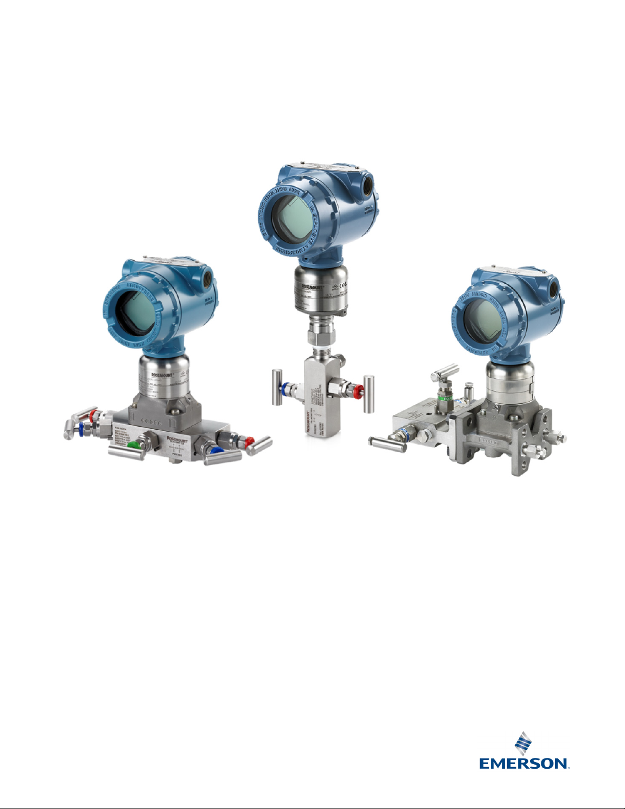
Rosemount™ Manifold Solutions
Product Data Sheet
January 2019
00813-0100-4733, Rev RA
Factory assembled, leak-tested, and calibrated
Full breadth offering including integral, in-line, and conventional styles
Integral design enables “flangeless” connection to instrument reducing weight, space, and leak points
Block-and-bleed, 2-, 3-, and 5-valve configurations
Compact, lightweight design
Easy in-process calibration
Direct-mount capability
Available in NACE
Available with Pressure-Lock
®
-compliant materials of construction
™
Valve
Page 2
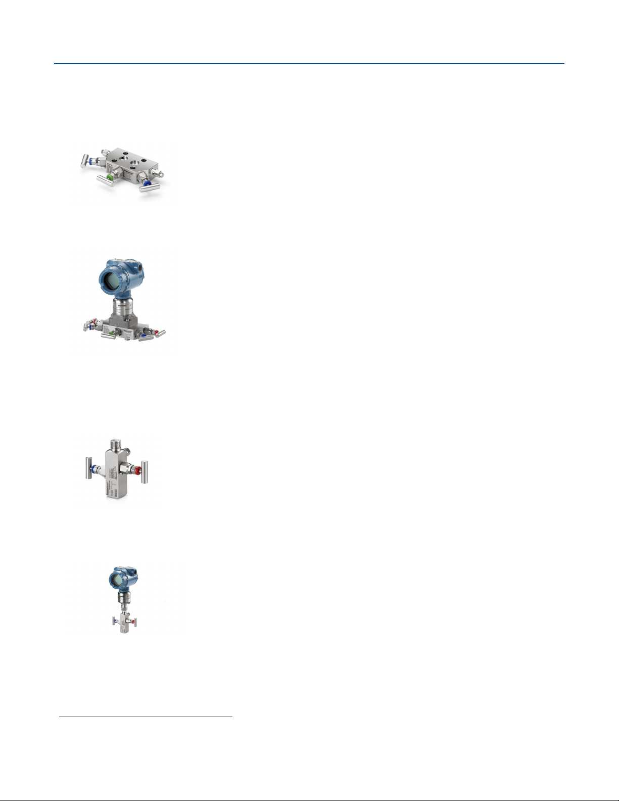
Rosemount Manifolds
Rosemount
R305 three-valve manifold
Rosemount 3051S assembled
to R305 five-valve manifold
Rosemount R306 two-valve
manifold
Rosemount 3051S assembled
to 306 two-valve manifold
Selection guide
Rosemount 305 Coplanar Style
Standard features
Assembled directly to transmitter, eliminating the need for flange
Factory leak tested and calibrated
Two, three, and five-valve configurations
Available with female NPT process connections
No exposed bolt configuration enhances reliability
50 percent fewer leak points than conventional transmitter to flange to manifold interface
Special cleaning options available
Rosemount 305 available with five-valve natural gas metering pattern
Rosemount R305 exclusive features
Pressure-Lock Valve with two-piece stem design
Large internal process bore to resist plugging
January 2019
Rosemount 306 In-line Style
(1)
Standard features
Assembled directly to transmitter or Rosemount Pressure Gauge
Factory leak tested and calibrated
Block-and-bleed and two-valve configurations
Available with female NPT process connections
Special cleaning options available
(1)
Rosemount R306 exclusive features
Pressure-Lock Valve with two-piece stem design
Large internal process bore to resist plugging
1. Rosemount R306 manifold only available with two-valve configuration.
2
Emerson.com/Rosemount
Page 3
January 2019
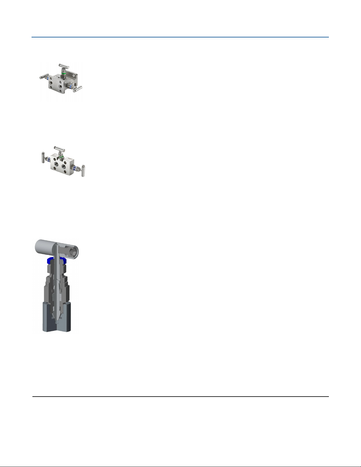
Rosemount 304
three-valve conventional
manifold
Rosemount 304 conventional
manifold - wafer style
Rosemount 304 Conventional Style
Standard features
Attaches to transmitter flange
Two, three, and five-valve configuration
Traditional (flange x flange, flange x NPT) and wafer styles
Available with five-valve natural gas metering pattern
Factory assembled, seal-tested, and calibrated
Rosemount Manifolds
Rosemount Pressure-Lock Valve
Exclusively featured on the Rosemount R305 and R306 manifolds
Pressure-Lock Valve, reference detailed design on page 27
Simplified operation
Two-piece valve stem design provides easier handle turn operation
Increased operator safety
Needle tip safety back seating ensures operator safety during process blowout events
Enhanced reliability
Process isolated stem threads increase overall valve life
Contents
Valve configuration . . . . . . . . . . . . . . . . . . . . . . . . . . . . . . . 4
Ordering information . . . . . . . . . . . . . . . . . . . . . . . . . . . . . 5
Emerson.com/Rosemount
Specifications . . . . . . . . . . . . . . . . . . . . . . . . . . . . . . . . . . .18
Dimensional drawings . . . . . . . . . . . . . . . . . . . . . . . . . . . .28
3
Page 4
Rosemount Manifolds
Isolate
Transmitter
Bleed screw
Process
Transmitter
Vent
Isolate
Process
Transmitter
Equalize
Process
IsolateIsolate
Valve configuration
January 2019
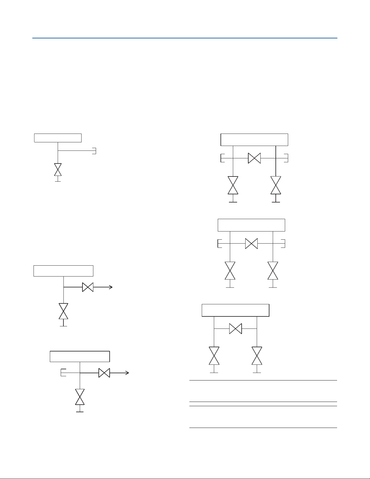
Block-and-bleed
The block-and-bleed configuration is available on the
Rosemount R306/306 Manifolds for use with in-line gage and
absolute pressure transmitters. A single isolate valve provides
instrument isolation and a bleed screw provides drain/vent
capabilities.
Rosemount 306 Manifold
Two-valve
The two valve configuration is available on Rosemount
R305/305, R306/306, and 304 Manifolds for use with absolute
and gage pressure transmitters. An isolate valve provides
instrument isolation and a drain/vent valve allows venting,
draining, or calibration.
Rosemount R305/305 and R306/306 Manifolds
Three-valve
The three valve configuration is available on Rosemount
R305/305 and 304 Manifolds for use with differential pressure
and multi-variable transmitters. Two isolate valves provide
instrument isolation, and one equalize valve is positioned
between the high and low process connections.
Rosemount R305/305 Manifolds
Transmitter
Drain/vent
Equalize
Isolate
Process
Rosemount 304 (traditional) Manifold
Transmitter
(plugged)
Equalize
Drain/vent
Isolate
(plugged)
Rosemount 304 Manifold
Transmitter
Isolate
Process
Isolate
Process
Isolate
Rosemount 304 (wafer) Manifold
Vent(plugged)
Note
Vent ports receive plastic caps to protect threaded connections
unless otherwise noted.
Note
Plugged connections receive
noted.
1
/4-in. NPT plugs unless otherwise
4
Emerson.com/Rosemount
Page 5
January 2019
Transmitter
Vent
Vent
Equalize
Process
IsolateIsolate
Transmitter
Equalize
Process
Equalize
Process
IsolateIsolate
(plugged)(plugged)
Vent
(closed)
Rosemount Manifolds
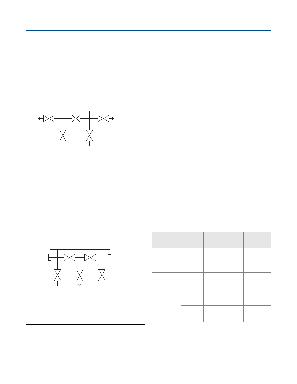
Five-valve
The five valve configuration is available on Rosemount R305/305
and 304 Manifolds for use with differential pressure and
multi-variable transmitters. Two isolate valves provide
instrument isolation and one equalize valve is positioned
between the high and low process connections. In addition, two
drain/vent valves allow for controlled venting, 100 percent
capture of vented or drained process, and simplified in-process
calibration capability.
Rosemount R305/305 Manifolds and 304 (wafer)
Five-valve natural gas
The five valve natural gas configuration is available on the
Rosemount 305 and 304 Manifolds for use with differential
pressure and multi-variable transmitters. Two isolate valves
provide instrument isolation and a single drain/vent valve allows
for controlled venting, 100 percent capture of vented or drained
process, and simplified in-process calibration capability. In
addition, two equalize valves provide extra protection from
leaking to ensure DP signal integrity.
“NG” option includes wide handle pattern and soft seats for
ease of use as well as a larger bore to reduce plugging
Ordering information
Rosemount Manifolds can be ordered as a stand-alone product
or as an integrated assembly attached to a transmitter.
Stand-alone manifold
1. Reference the “Selection guide” on page 2 for assistance
on choosing the type of manifold.
2. Specify a completed model number by referencing the
applicable ordering table for the selected manifold type:
Rosemount 305 Integral Manifold, see page 6.
Rosemount 306 In-line Manifold, see page 11.
Rosemount 304 Conventional Manifold, see page 15.
Transmitter/manifold assembly
1. Specify a completed Rosemount transmitter model
number by referencing the applicable product data sheet.
2. Specify a completed manifold model number by
referencing the applicable ordering table for the selected
manifold type:
Rosemount 305 Integral Manifold, see page 6.
Rosemount 306 In-line Manifold, see page 11
Rosemount 304 Conventional Manifold, see page 15.
3. Verify the transmitter model number contains the correct
“Process Connection” code or “Manifold Option” code for
the desired transmitter manifold assembly (see Tabl e 1).
Table 1. Ordering Codes for a Transmitter/Manifold
Assembly
Rosemount 305 Manifolds and 304 (traditional)
Note
Vent ports receive plastic caps to protect threaded connections
unless otherwise noted.
Note
Plugged connections receive 1/4-in. NPT plugs unless otherwise
noted.
Emerson.com/Rosemount
Tra ns mit te r
Rosemount
3051S
Rosemount
3051/2051
Rosemount
2088
Manifold
R305/305 A11 N/A
R306/306 A11 N/A
304 A12 N/A
R305/305 N/A S5
R306/306 N/A S5
304 N/A S6
R305/305 N/A N/A
R306/306 N/A S5
304 N/A N/A
Process
connection code
“Manifold”
option code
5
Page 6
Rosemount Manifolds
January 2019
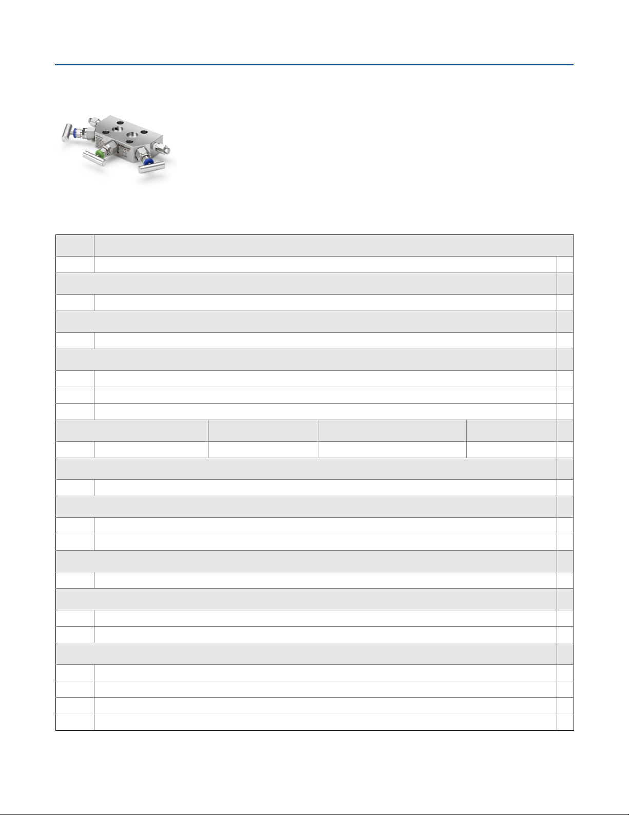
Rosemount 305 Coplanar Manifolds
Rosemount Coplanar manifolds provide a leak checked and pressure tested single point solution
when assembled to Rosemount pressure transmitters. The coplanar platform reduces potential leak
paths by 50 percent over conventional style process connections while also reducing overall
connection system weight.
Specification and selection of product materials, options, or components must be made by the
purchaser of the equipment. See page 18 for more information on material selection.
Table 2. Rosemount R305 Integral Manifold Ordering Information
The starred offerings (★) represent the most common options and should be selected for best delivery. The non-starred offerings are subject
to additional delivery lead time.
Model Product description
R305 Integral manifold
Design class
E Enhanced ★
Manifold style
C Coplanar ★
Manifold type
2 Two valve ★
3 Three valve ★
5 Five valve ★
(1)
Body
2 316 stainless steel (SST) 316 SST 316 SST 316 SST ★
Bonnet Stem and tip Drain/vent
Process connection
B
1
/2–14 NPT female ★
Packing material
(2)
1
(3)
2
PTFE ★
Graphite-based
Valve seat
1 Integral ★
Extended product warranty
WR3 3-year limited product warranty
WR5 5-year limited product warranty
Mounting bracket
B4 316 SST mounting bracket for 2-in. pipe mount with series 300 SST bolts
BE 316 SST bracket for 2-in pipe mount with 316 SST bolts
BF Carbon steel (CS) panel mount bracket
BG 316 Series SST panel mount bracket
6
Emerson.com/Rosemount
Page 7
January 2019
Rosemount Manifolds
Table 2. Rosemount R305 Integral Manifold Ordering Information
The starred offerings (★) represent the most common options and should be selected for best delivery. The non-starred offerings are subject
to additional delivery lead time.
Bolting Materials
L4
Austenitic 316 SST bolts
L5 ASTM A 193 B7M bolts
L8 ASTM A 193,Class 2, Grade B8M bolts
Cleaning
P2
Material recommendation for NACE
SG
(4)
Cleaning for special services
(5)
Sour gas (meets NACE MR 0175/ISO 15156, MR 0103)
NACE Certificate
Q15 Certificate of Compliance to NACE MR0175/ISO 15156 for wetted materials ★
Q25 Certificate of Compliance to NACE MR0103 for wetted materials ★
Additional options
DS Drain vent screen ★
Bolts
TD
For assembly to Rosemount 3051D
Typical coplanar integral manifold model number: R305EC32B11B4
1. Refer to page 18 for additional detail on process wetted materials of construction.
2. Includes PTFE tape on drain/vent valves and plugs.
3. Includes graphite tape on drain/vent valves and plugs.
4. Not available with graphite-based packing material code 2 .
5. Valve stem tip material is C-276.
★
Emerson.com/Rosemount
7
Page 8
Rosemount Manifolds
January 2019
Specification and selection of product materials, options, or components must be made by the purchaser of the equipment.
See page 18 for more information on material selection.
Table 3. Rosemount 305 Integral Manifold Ordering Information
The starred offerings (★) represent the most common options and should be selected for best delivery. The non-starred offerings are subject
to additional delivery lead time.
Model Product description
0305 Integral manifold
Manufacturer
R Rosemount ★
Manifold style
C Coplanar ★
T Traditional ★
M Traditional (DIN-compliant flange) ★
Manifold type
2 Two valve ★
3 Three valve ★
(1)
5
(2)
6
(2)(3)
7
(2)(3)
8
(2)(3)
9
Body
Five valve ★
Five valve natural gas metering pattern ★
Two valve (per ASME B31.1 [ANSI] power and piping code)
Three valve (per ASME B31.1 [ANSI] power and piping code)
Five valve (per ASME B31.1 [ANSI] power and piping code)
(4)
Bonnet Stem and tip/ball
2 316 SST/316L SST 316 SST 316 SST ★
(5)
3
4
8
9
(5)(6)
(7)
(7)
Alloy C-276 Alloy C-276 Alloy C-276
Alloy 400 Alloy 400 Alloy 400
Alloy 625 Alloy 625 Alloy 625
All super duplex SST (UNS S32760)
Process connection style
(8)
A
(9)
B
1
/4–18 NPT female ★
1
/2–14 NPT female ★
Packing material
(10)
1
(11)
2
PTFE ★
Graphite-based
Valve seat
1 Integral ★
5 Soft POM (only available with natural gas metering pattern) ★
8
Emerson.com/Rosemount
Page 9
January 2019
Rosemount Manifolds
Table 3. Rosemount 305 Integral Manifold Ordering Information
The starred offerings (★) represent the most common options and should be selected for best delivery. The non-starred offerings are subject
to additional delivery lead time.
Options
Extended product warranty
WR3 3-year limited warranty ★
WR5 5-year limited warranty
Mounting brackets
B1 Bracket for 2-in. pipe mounting, CS bolts ★
(12)
B3
B4 SST mounting bracket for 2-in. pipe mounting, 300 SST bolts ★
B7 B1 bracket with 316 SST bolts ★
B9
BA 316 SST B1 bracket with 316 SST bolts ★
BC
BE 316 SST B4 bracket with 316 SST bolts ★
BF CS panel mount bracket ★
BG 316 SST panel mount bracket ★
Flat bracket for 2-in. pipe mounting, CS bolts ★
(12)
B3 bracket with 316 SST bolts ★
(12)
316 SST B3 bracket with 316 SST bolts ★
★
Bolt materials
(13)
L4
Austenitic 316 SST bolts ★
L5 ASTM A193, Grade B7M bolts ★
L8 ASTM A193, Class 2, Grade B8M bolts ★
Cleaning
(14)
P2 Cleaning for special services ★
Material recommendations for NACE
(5)(15)
SG Sour gas (meets NACE MR0175/ISO 15156, MR0103/ISO 17495) ★
Adapters
DF
(16)
1
/2–14 NPT female flange adapter ★
DQ 12 mm ferrule tube flange adapter
Cold temperature
(17)
CW1 –67 °F (–55 °C) cold temperature operation
Process flow meter configuration
PF Relocated equalize valve for 9295 process flow meter
Process flange bolting connection
HK 10 mm (M10) process flange bolting connection ★
HL 12 mm (M12) process flange bolting connection ★
(18)
Typical coplanar integral manifold model number: 305 R C 3 2 B 1 1 B4
1. Not available with traditional manifold style T.
Emerson.com/Rosemount
9
Page 10

Rosemount Manifolds
2. Only available with coplanar manifold style code C.
3. Only available with 316 SST materials of construction code 2 and graphite-based packing code 2.
4. Refer to page 25 for additional detail on process wetted materials of construction.
5. Materials of construction comply with recommendations per NACE MR0175/ISO 15156 for sour oil field production environments. Environmental limits apply to
certain materials. Consult latest standard for details. Selected materials also conform to NACE MR0103/ISO 17495 for sour refining environments.
6. Includes Alloy C - 276 drain vents.
7. Only available with two, three and five-valve manifold type.
8. Only available with traditio nal manifold style codes T and M.
9. Not available with traditional manifold style code M. Manifold style code T does not include mounting holes on process flange.
10. Includes PTFE tape on drain/vent valves and plugs.
11. Includes graphite tape on drain/vent valves and plugs.
12. Not compatible with the Rosemount 3095 Transmitter.
13. Not available with ASME B31.1 manifold type codes 7, 8, and 9.
14. Not available with graphite-based packing material code 2.
15. Only allowed with material of construction code 2.
16. Only allowed with traditional manifold style codes T and M. Not allowed with graphite-based packing code 2.
17. Only available with two, three, and five- valve manifold type, 316SST or Alloy C-276 materials of construction and integral valve seat.
18. Only available with traditional manifold style code M.
January 2019
10
Emerson.com/Rosemount
Page 11
January 2019
Rosemount Manifolds
Rosemount 306 In-line Manifolds
Rosemount In-Line manifolds provide a leak checked and pressure tested single point solution when
assembled to Rosemount pressure transmitters. The in-line, compact design is available with a lightweight
block and bleed or two-valve configurations.
Specification and selection of product materials, options, or components must be made by the purchaser
of the equipment. See page 18 for more information on material selection.
Table 4. Rosemount R306 Integral Manifold Ordering Information
The starred offerings (★) represent the most common options and should be selected for best delivery. The non-starred offerings are subject
to additional delivery lead time.
Model Product description
R306 Integral manifold
Design class
E Enhanced ★
Manifold style
T Threaded ★
Manifold type
2 2-valve ★
Body Bonnet Stem and tip Drain/vent
2 316 SST 316 SST 316 SST 316 SST ★
Process connection
BA
1
/2–14 female ANPT process connection for in-line transmitter ★
Packing material
(1)
1
(2)
2
PTFE ★
Graphite-based
Valve seat
1 Integral ★
Extended product warranty
WR3 3-year limited product warranty
WR5 5-year limited product warranty
Cleaning
P2
Material recommendation for NACE
(3)
Cleaning for special services
(4)
SG
Sour gas (meets NACE MR MR 0175/ISO 15156, MR 0103)
NACE Certificate
Q15 Certificate of Compliance to NACE MR0175/ISO 15156 for wetted materials ★
Q25 Certificate of Compliance to NACE MR0103 for wetted materials
Typical coplanar integral manifold model number: R306ET22BA11
Emerson.com/Rosemount
★
11
Page 12

Rosemount Manifolds
1. Includes PTFE tape on drain/vent valves and plugs.
2. Includes graphite tape on drain/vent valves and plugs.
3. Not available with graphite-based packing material code 2 .
4. Valve stem tip material is C-276.
January 2019
12
Emerson.com/Rosemount
Page 13
January 2019
Rosemount Manifolds
Specification and selection of product materials, options, or components must be made by the purchaser of the equipment.
See page 18 for more information on material selection.
Table 5. Rosemount 306 Pressure Manifold Ordering Information
The starred offerings (★) represent the most common options and should be selected for best delivery. The non-starred offerings are subject
to additional delivery lead time.
Model Product description
0306 Pressure manifold
Manufacturer
R Rosemount ★
Manifold style
T Threaded ★
Manifold type
1 Block-and-bleed ★
2 Two valve ★
(1)
3
Body
(2)
Two valve (per ASME B31.1 power piping code)
Bonnet Stem and tip/ball
2 316/316L SST 316 SST 316 SST ★
(3)(4)
3
(3)
4
(3)
8
(3)
9
Alloy C-276 Alloy C-276 Alloy C-276
Alloy 400 Alloy 400 Alloy 400/K-500
Alloy 625 Alloy 625 Alloy 625
All super duplex SST (UNS S32760)
Process connection
AA
AW
BA
BW
(3)
1
/2–14 male NPT process connection for in-line transmitter ★
1
/2–14 male NPT process connection for Rosemount Wireless Pressure Gauge ★
1
/2–14 female NPT process connection for in-line transmitter ★
1
/2–14 female NPT process connection for Rosemount Wireless Pressure Gauge ★
Packing material
(5)
1
(6)
2
PTFE ★
Graphite-based
Valve seat
1 Integral ★
Options
Extended product warranty
WR3 3-year limited warranty ★
WR5 5-year limited warranty
Emerson.com/Rosemount
★
13
Page 14

Rosemount Manifolds
January 2019
Table 5. Rosemount 306 Pressure Manifold Ordering Information
The starred offerings (★) represent the most common options and should be selected for best delivery. The non-starred offerings are subject
to additional delivery lead time.
Cleaning
(7)
P2 Cleaning for special services
Cold temperature
(8)
CW1 –67 °F (–55 °C)
(4)(9)
Material recommendations for NACE
SG Sour gas (meets NACE MR0175/ISO 15156, MR0103/ISO 17495) ★
Typical integral manifold model number: 306 R T 2 2 BA 1 1
1. Only available with 316 SST materials of construction and graphite-based packing.
2. Refer to page 25 for additional detail on process wetted materials of construction.
3. Not available with block-and-bleed manifold type.
4. Materials of Construction comply with recommendations per NACE MR0175/ISO 15156 for sour oil field production environments. Environmental limits apply to
certain materials. Consult latest standard for details. Selected materials also conform to NACE MR0103/ISO 17495 for sour refining environments.
5. Includes PTFE tape on drain/vent valves and plugs.
6. Includes graphite tape on plugs.
7. Not available with graphite-based packing material code 2 .
8. Only available with two-valve manifold type, 316SST or Alloy C-276 materials of construction,
transmitters and integral valve seat.
9. Only allowed with material of construction code 2.
1
/2–14 male and female NPT process connection for in-line
14
Emerson.com/Rosemount
Page 15

January 2019
Rosemount Manifolds
Rosemount 304 Conventional Manifolds
Rosemount Conventional manifolds provide a leak checked and pressure tested single point solution
when assembled to Rosemount pressure transmitters. The conventional platform delivers a like-for-like
replacement for traditional style manifolds with threaded or flanged side process entries.
Specification and selection of product materials, options, or components must be made by the purchaser
of the equipment. See page 18 for more information on material selection.
Table 6. Rosemount 304 Conventional Manifold Ordering Information
The starred offerings (★) represent the most common options and should be selected for best delivery. The non-starred offerings are subject
to additional delivery lead time.
Model Product description
0304 Conventional manifold
Manufacturer
R Rosemount ★
Manifold style
T Traditional (flange x flange or flange x NPT) ★
(1)
W
Wafer
Manifold type
(2)
2
Two valve ★
3 Three valve ★
(3)
5
(2)
6
(2)(4)
7
(2)(4)
8
Body
(5)
Five valve ★
Five valve natural gas metering pattern ★
Two valve (per ASME B31.1 [ANSI] power and piping code)
Three valve (per ASME B31.1 [ANSI] power and piping code)
Bonnet Stem Tip
2 316/316L SST 316 SST 316 SST 316 SST ★
(6)
4
Alloy 400 Alloy 400/R-405 Alloy 400/R-405 Alloy 400
5 CS 316 SST 316 SST 316 SST ★
Process connection style
B
(2)
F
1
/2–14 NPT ★
Flanged ★
Packing/stem seal material
(7)
1
(1)(8)
2
Graphite-based
(9)
3
PTFE ★
FKM elastomer O-ring ★
Bolts
1 For assembly to Rosemount 2051/3051 traditional flange ★
2 For assembly to Rosemount 2051/3051 DIN-compliant traditional flange ★
3 For assembly to Rosemount 2051/3051 Coplanar™ flange ★
Emerson.com/Rosemount
15
Page 16
Rosemount Manifolds
January 2019
Table 6. Rosemount 304 Conventional Manifold Ordering Information
The starred offerings (★) represent the most common options and should be selected for best delivery. The non-starred offerings are subject
to additional delivery lead time.
Options
Gas-metering configuration
(10)
NG Wide handle pattern, 3/8-in. bore, soft POM seat ★
Extended product warranty
WR3 3-year limited warranty ★
WR5 5-year limited warranty
Mounting brackets
(2)
VC
(2)
VS
(3)
B4
Adapters and connectors
DF
DT
DQ 12 mm ferrule tube flange adapter ★
(12)
DV
(12)
DH
Dielectric isolator kits
Manifold heavy duty mounting bracket, CS for traditional style ★
Manifold heavy duty mounting bracket, 316 SST for traditional style ★
Manifold SST mounting bracket for 2-in. pipe mount with series 300 SST bolts for wafer style ★
(11)
1
/2–14 NPT female flange adapter ★
1
/2-in. ferrule tube flange adapter ★
1
/2–14 NPT male non-stabilized connectors ★
1
/2–14 NPT male stabilized extended connectors ★
(13)
★
G2 Dielectric isolators and bolt sleeves for connectors ★
Bolt material
(14)
L4
Austenitic 316 SST bolts ★
L5 ASTM A193, Grade B7M bolts ★
L8 ASTM A193, Class 2, Grade B8M bolts ★
Material recommendations for NACE
(1)(15)
SG Sour gas (meets NACE MR0175/ISO 15156, MR0103/ISO 17954) ★
Cleaning
(16)
P2 Cleaning for special service
Heater block kits
(17)
SB Steam block kit, 1/4-in. NPT connection ★
Typical model number: 0304 R T 3 2 B 1 1 VS
1. Only allowed with material of construction code 2.
2. Not available with wafer manifold style code W.
3. Not available with traditional manifold style code T.
4. Only available with 316 SST materials of construction code 2 and graphite-based packing code 2.
5. Refer to page 25 for additional detail on process wetted materials of construction.
16
Emerson.com/Rosemount
Page 17

January 2019
6. Only available with wafer manifold style and two-valve manifold type.
7. Includes PTFE tape on drain/vent valves and plugs.
8. Includes graphite tape on plugs.
9. Only available with option code NG.
10. Only available with manifold type code 6.
11. Only allowed with both manifold style code T and process connection code F. Not allowed with graphite-based packing code 2.
12. Only available with manifold style code 6.
13. Only available with option codes DV and DH.
14. Not available with manifold type codes 7, 8.
15. Materials of construction comply with recommendations per NACE MR0175/ISO 1516 for sour oil field production environments. Environmental limits apply to
certain materials. Consult latest standard for details. Selected materials also conform to NACE MR0103/ISO 17495 for sour refining environments.
16. Not available with Graphite-based packing material code 2.
17. Not available with manifold type code 6.
Rosemount Manifolds
Emerson.com/Rosemount
17
Page 18

Rosemount Manifolds
January 2019
Specifications
Material selection
Emerson™ provides a variety of Rosemount product with various product options and configurations including materials of
construction that can be expected to perform well in a wide range of applications. The Rosemount product information presented is
intended as a guide for the purchaser to make an appropriate selection for the application. It is the purchaser’s sole responsibility to
make a careful analysis of all process parameters (e.g. all chemical components, temperature, pressure, flow rate, abrasives,
contaminants), when specifying product, materials, options and components for the particular application. Emerson is not in a
position to evaluate or guarantee the compatibility of the process fluid or other process parameters with the product, options,
configuration or materials of construction selected. For more information on material compatibility, refer to the Material Selection
Tech nical Note.
Pressure and temperature ratings
Figure 1. Rosemount R305 Integral Manifolds
Table 7. Rosemount R305 Integral Manifolds
Packing Seat Pressure and temperature ratings
PTFE
Integral
Graphite
18
6250 psi at –40 to 200 °F (431 bar at –40 to 93 °C)
4000 psi at 400 °F (276 bar at 204 °C)
6250 psi at –40 to 200 °F (431 bar at –40 to 93 °C)
1500 psi at 750 °F (103 bar at 399 °C)
Emerson.com/Rosemount
Page 19

January 2019
Figure 2. Rosemount 305 Integral Manifolds
Rosemount Manifolds
Table 8. Rosemount 305 Integral Manifolds
(1)
Packing Seat Pressure and temperature ratings
PTFE
Integral
Soft POM 6092 psi at –40 to 200 °F (420 bar at –40 to 93 °C)
Graphite
Integral
Graphite (ASME B31.1)
1. Except option HK:
PTFE, integral seat: 2324 psi at 200 °F (160 bar at 93 °C), 1680 psi at 400 °F (116 bar at 204 °C)
Graphite, integral seat: 2324 psi at 200 °F (160 bar at 93 °C), 1125 psi at 750 °F (78 bar at 399 °C)
6092 psi at –40 to 200 °F (420 bar at –40 to 93 °C)
4000 psi at 400 °F (276 bar at 204 °C)
6092 psi at –40 to 200 °F (420 bar at –40 to 93 °C)
1500 psi at 750 °F (103 bar at 399 °C)
6092 psi at –40 to 100 °F (420 bar at –40 to 38 °C)
3030 psi at 1000 °F (209 bar at 538 °C)
Emerson.com/Rosemount
19
Page 20

Rosemount Manifolds
Figure 3. Rosemount R306 In-Line Manifolds
January 2019
Table 9. Rosemount R306 In-Line Manifolds
Packing Seat Pressure and temperature ratings
PTFE
Integral
Graphite
10000 psi at –40 to 85 °F (689 bar at –40 to 29 °C)
4000 psi at 400 °F (276 bar at 204 °C)
6250 psi at –40 to 200 °F (431 bar at –40 to 93 °C)
1500 psi at 750 °F (103 bar at 399 °C)
20
Emerson.com/Rosemount
Page 21

January 2019
Figure 4. Rosemount 306 In-line Manifolds
Rosemount Manifolds
Table 10. Rosemount 306 In-line Manifolds
Packing Seat Pressure and temperature ratings
PTFE
Graphite
Graphite (ASME B31.1)
Integral
10000 psi at –40 to 85 °F (689 bar at –40 to 29 °C)
4000 psi at 400 °F (276 bar at 204 °C)
6000 psi at –40 to 200 °F (414 bar at –40 to 93 °C)
1500 psi at 750 °F (103 bar at 399 °C)
6000 psi at –40 to 100 °F (414 bar at –40 to 38 °C)
3030 psi at 1000 °F (209 bar at 538 °C)
Emerson.com/Rosemount
21
Page 22

Rosemount Manifolds
Figure 5. Rosemount 304 Conventional Manifolds
January 2019
Table 11. Rosemount 304 Conventional Manifolds
Packing Seat Pressure and temperature ratings
(1)
PTFE
Graphite - wafer
Graphite - flanged (SST)
Graphite - flanged (CS)
Graphite (ASME B31.1)
PTFE
FKM O-ring 4500 psi at –13 to 212°F (310 bar at –25 to 100 °C)
1. Maximum working pressure limited to 4500 psi (310 bar) with G2 option.
Integral
POM
6000 psi at –40 to 200 °F (414 bar at –40 to 93 °C)
4000 psi at 400 °F (276 bar at 204 °C)
6000 psi at –40 to 200 °F (414 bar at –40 to 93 °C)
1500 psi at 750 °F (103 bar at 399 °C)
6000 psi at –40 to 200 °F (414 bar at –40 to 93 °C)
1500 psi at 1000 °F (103 bar at 538 °C)
6000 psi at –40 to 200 °F (414 bar at –40 to 93 °C)
1500 psi at 800 °F (103 bar at 427 °C)
6000 psi at –40 to 100 °F (414 bar at –40 to 38 °C)
3030 psi at 1000 °F (209 bar at 538 °C)
4500 psi at –67 to 212°F (310 bar at –55 to 100 °C)
22
Emerson.com/Rosemount
Page 23

January 2019
Instrument connections
Table 12. Manifold - Transmitter Interface
Model Connection
Rosemount Manifolds
Rosemount R305/305 Integral
Manifold
Rosemount R306/306 In-line
Manifold
Rosemount 304 Conventional
Manifold
Mounted directly to coplanar sensor module of transmitter, 1.3-in. (287 mm) center-to-center
process isolators
1
/2–14 male NPT for In-line transmitters 1/2-14 female NPT for Rosemount Wireless Pressure
Gauge
Mounted to traditional transmitter flange, 21/8-in. (54 mm) center-to-center connection per
IEC 61518, type B shut-off device (without spigot)
O-rings
Figure 6. Rosemount R305/305 Integral Manifold
Sensor module-to-manifold O-rings
Specified in the transmitter model number.
Figure 7. Rosemount 304 Conventional Manifold
Manifold-to-flange O-rings
Same material as specified by manifold “Packing Material” selection.
Flange adapter O-rings
Glass-filled PTFE
1. Available in packing material code 1 (PTFE) or code 2 (Graphite).
Emerson.com/Rosemount
(1)
23
Page 24

Rosemount Manifolds
January 2019
Process connections
Table 13. Rosemount R305/305 Integral Manifold
Style Connection
Coplanar
Traditional
Table 14. Rosemount R306/306 In-line Manifold
Style Connection
Block-and-bleed1/2–14 male NPT
2-valve
1.1/2-14 female NPT option only available with Wireless Pressure Gauge.
Table 15. Rosemount 304 Conventional Manifold
Style Connection
Flange by pipe
Flange by flange
Wafer
1
/2–14 female NPT
1
/4–18 female NPT
(process adapters optional)
(1)
1
/2–14 NPT (male or female)
1
/2–14 female NPT
21/8-in. (54 mm) center-to-center
connection (process adapters required)
1
/2-14 female NPT
Table 16. Adapters and Connectors
Option Description
Image
Non-stabilized connector
DV
(1)
• 3.00-in.
• No stabilizing foot
• Includes assembly hardware
Stabilized extended connectors
DH
(1)
• 4.75-in.
• Stabilizing foot
• Includes assembly hardware
Dielectric isolators
(1)(2)
G2
1. Only allowed with both Rosemount 304 Manifold type code 6 and process
connection code F. Not allowed with Graphite- based packing code 2.
2. Maximum working pressure of assembly limited to 4500 psi (310 bar),
3626 psi (250 bar) at –20 °F (–29 °C), and 3626 psi (250 bar) at 150 °F (66 °C).
• Rated to 2500 VDC and 5 megaOhms
• Includes bolts sleeves and
assembly hardware
Vent port connections
1
/4–18 female NPT
Table 16. Adapters and Connectors
Option Description
1
/2-14 NPT female flange adapter
DF
DT
DQ
• Available with Rosemount 305
Integral and 304 Conventional
Manifolds
1
/2-in. ferrule tube flange
adapter
• Available with Rosemount 304
Conventional Manifold
12mm ferrule tube flange
adapter
• Available with Rosemount 305
Integral and 304 Conventional
Manifolds
Image
Table 17. Spare Part Adapters and Connectors
Spare part number Description Image
Socket weld adapter
03031–1320–XXXX
(1)
1. Complete part numbers for specific socket weld adapter kits can be found
on page 42.
kit
• 3.00-in.
• For traditional
flange
Manifold bolts
Standard material is plated CS per ASTM A449, type 1
Alternative bolt materials offered through option codes:
L4 for Austenitic 316 SST bolts
L5 for ASTM A193, Grade B7M bolts
L8 for ASTM A193, Grade B8M Class 2 bolts
24
Emerson.com/Rosemount
Page 25
January 2019
A
B
C
D
E
Rosemount Manifolds
Materials of construction
Process wetted
Table 18. Rosemount R305 Integral Manifold
Component Option 2 Option 2 with SG
Body 316 SST/316L SST 316 SST/316L SST
Stem 316 SST/316L SST Alloy C-276
Tip 316 SST Alloy C-276
Packing PTFE/graphite PTFE/graphite
Bonnet 316 SST 316 SST
Pipe plug 316 SST 316 SST
Drain/vent valve 316 SST Alloy C-276
Table 19. Rosemount 305 Integral Manifold
Component Option 2
Body
Ball/tip
Stem 316 SST
Packing
Bonnet 316 SST 316 SST Alloy C-276 Alloy 400
Pipe plug 316 SST 316 SST Alloy C-276 Alloy 400
Drain/vent
valve
Table 20. Rosemount R306 In-line Manifold
316 SST/
316L SST
316 SST/
316Ti SST
PTFE/
Graphite
316 SST
Option 2
with SG
316 SST/
316L SST
Alloy
C-276
Alloy
C-276
PTFE/
Graphite
Alloy
C-276
Option 3 Option 4
Alloy C-276 Alloy 400
Alloy C-276 Alloy 400
Alloy C-276 Alloy 400
PTFE/
Graphite
Alloy C-276 Alloy 400
PTFE/
Graphite
Table 21. Rosemount 306 In-line Manifold
Component Option 2
Body
Ball/tip
Stem 316 SST Alloy C-276 Alloy C-276
Packing
Bonnet 316 SST 316 SST Alloy C-276
Pipe plug 316 SST 316 SST Alloy C-276
Bleed screw
Table 22. Rosemount 304 Conventional Manifold
316 SST/
316L SST
316 SST/
316Ti SST
PTFE/
Graphite
316 SST/
316Ti SST
Component Option 2
Body
Ball/tip
Stem 316 SST Alloy C-276 316 SST
Packing
Bonnet 316 SST 316 SST CS
Pipe plug 316 SST 316 SST CS
316 SST/
316L SST
316 SST/
316Ti SST
PTFE/
Graphite
Option 2
with SG
316 SST/
316L SST
Alloy C-276 Alloy C-276
PTFE/
Graphite
Alloy C-276 Alloy C-276
Option 2
with SG
316 SST/
316L SST
Alloy C-276 316 SST
PTFE/
Graphite
Option 3
Alloy C-276
PTFE/
Graphite
Option 5
CS
PTFE
Typi cal
Component Option 2 Option 2 with SG
Body 316 SST/316L SST 316 SST/316L SST
Stem 316 SST/316L SST Alloy C-276
Tip 316 SST Alloy C-276
Packing PTFE/graphite PTFE/graphite
Bonnet 316 SST 316 SST
Pipe plug 316 SST 316 SST
Drain/vent valve 316 SST Alloy C-276
Emerson.com/Rosemount
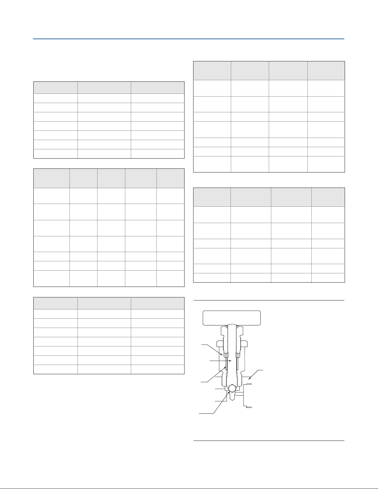
Figure 8. Rosemount 305,306, and 304 Manifold Valve
A. Bonnet
B. Stem
C. Packing
D. Ball/tip
E. Body
25
Page 26

Rosemount Manifolds
Estimated weight
Table 23. Rosemount R305/305 Integral Manifold
January 2019
Description
2-valve coplanar 4.5 lb (2.0 kg)
2-valve traditional 6.0 lb (2.7 kg)
3-valve coplanar 4.7 lb (2.1 kg)
3-valve traditional 6.0 lb (2.7 kg)
5-valve coplanar 6.5 lb (3.0 kg)
Table 24. Rosemount R306/306 In-line Manifold
Description
Block-and-bleed 1.1 lb (0.5 kg)
2-valve 2.5 lb (1.1 kg)
7
Table 25. Rosemount 304 Conventional Manifold
Description
2-valve traditional flange x NPT 5.0 lb (2.3 kg)
2-valve traditional flange x flange 5.5 lb (2.5 kg)
3-valve traditional flange x NPT 5.2 lb (2.4 kg)
3-valve traditional flange x flange 5.7 lb (2.6 kg)
3-valve wafer flange x NPT 4.0 lb (1.8 kg)
5-valve wafer flange x NPT 5.7 lb (2.6 kg)
5-valve traditional flange x NPT 5.7 lb (2.6 kg)
5-valve traditional flange x flange 5.7 lb (2.6 kg)
Weight
Weight
Weight
26
Emerson.com/Rosemount
Page 27

January 2019
A
F
G
H
B
C
D
E
I
Rosemount Manifolds
Rosemount Pressure-Lock Valve Configuration
Exclusively featured on the Rosemount R305 and R306 manifolds, the Pressure-Lock Valve utilizes a two-piece stem design with a
non-rotating needle tip which offers the end user simplified operation, enhanced reliability and increased operator safety.
Figure 9. Rosemount Pressure-Lock Valve
Simplified operation
A. Removable handles - allows for a quick way of adding security
and reducing unwanted tampering.
B. Color-coded dust caps - reduces valve confusion, labeled to
indicate function.
C. Packing nut - allows for smooth adjustment of stem packing
D. Two-piece stem design with non-rotating tip - provides
smooth ergonomic operation, reduces potential leak paths
and decreases overall wear, extending valve life.
Increased operator safety
E. Safety back seating - provides integral blowout protection.
Enhanced reliability
F. Stem threads isolated from process fluid – increase
equipment life and operator safety
G. Modular packing – located below stem threads to isolate
thread from process fluid, preventing corrosion
H. Bonnet threads isolated from process fluid – improves
corrosion resistance and equipment life with metal to metal,
bonnet to body seal
I. One-piece needle tip stem – ensure seal integrity over wide
range of pressures and temperatures
Emerson.com/Rosemount
27
Page 28

Rosemount Manifolds
p
7.72
(196)
8.97
(228)
4.20
(107)
5.00
(127)
max open
B
A
4.51
(115)
5.17
(131)
9.20
(234)
max open
Dimensional drawings
January 2019
Rosemount coplanar style manifolds
(1)
Figure 10. Rosemount R305/305 Two Valve Coplanar Style Manifold
5.17
7.20
4.51
(115)
(131)
4.20
(107)
7.72
(196)
8.97
(228)
4.00
(102)
max o
en
A. 1/2–14 NPT on manifold for process connection, 1/4–18 NPT for test/vent connection
Dimensions are in inches (millimeters).
A
(183)
max open
Figure 11. Rosemount R305/305 Three Valve Coplanar Style Manifolds
A. Drain/vent valve
1
B.
/2–14 NPT on manifold for process connections, 21/8-in. center-to-center
Dimensions are in inches (millimeters).
1. Manifold handle assembly may vary slightly from image shown. All valve handle assemblies provide the same function and meet all stated drawing dimensions.
28
Emerson.com/Rosemount
Page 29

January 2019
7.72
(196)
8.97
(228)
4.20
(107)
5.00
(127)
max open
A
4.51
(115)
5.17
(131)
10.60
(269)
max open
4.20
(107)
7.72
(196)
4.51
(115)
5.17
(131)
6.40
(163)
max open
2.126
(54)
3.50
(89)
1.10
(28)
3.70
(94)
max open
1.63
(41)
A
B
Figure 12. Rosemount R305/305 Five Valve Coplanar Style Manifold
A. 1/2–14 NPT on manifold for process connections, 21/8-in. center-to-center, 1/4–18 NPT for test/vent connection
Dimensions are in inches (millimeters).
Rosemount Manifolds
Figure 13. Rosemount 305 Two Valve Traditional Style Manifold
A. 1/2–14 NPT on optional process adapter
1
B.
/4–18 NPT on traditional manifold for process connection without the use of a process adapter
Dimensions are in inches (millimeters).
Emerson.com/Rosemount
29
Page 30

Rosemount Manifolds
4.20
(107)
7.72
(196)
3.70
(94)
max open
3.50
(89)
1.10
(28)
1.16
(29)
4.51
(115)
5.17
(131)
1.63
(41)
6.40
(163)
max open
2.126
(54)
8.90
(226)
max open
A
B
C
Figure 14. Rosemount 305 Three Valve Traditional Style Manifold
January 2019
A. Drain/vent valve
1
B.
/2–14 NPT on optional process adapter
C. 1/4–18 NPT on traditional manifold for process connections without the use of process adapters
(1)
Dimensions are in inches (millimeters).
1. Adapters can be rotated to give adapter connection centers of 2.0 (51), 2.125 (54), or 2.25 (57).
Figure 15. Rosemount 305 Two Valve Traditional DIN Style Manifold
5.17
4.20
(107)
7.72
(196)
4.20
(107)
max open
1
/2–14 NPT on optional process adapter C. 1/4–18 NPT vent connection
A.
1
/4–18 NPT on traditional manifold for process connection without the use of a process adapter
B.
4.13
(105)
Dimensions are in inches (millimeters).
A
BC
1.10
(28)
6.46
(164)
max open
(115)
4.51
2.126
(131)
(54)
1.63
(41)
30
Emerson.com/Rosemount
Page 31
January 2019
4.20
(107)
7.72
(196)
4.20
(107)
max open
4.13
(105)
1.10
(28)
1.05
(27)
6.46
(164)
max open
2.126
(54)
9.02
(230)
max open
A
B
C
1.63
(41)
4.51
(115)
5.17
(131)
D
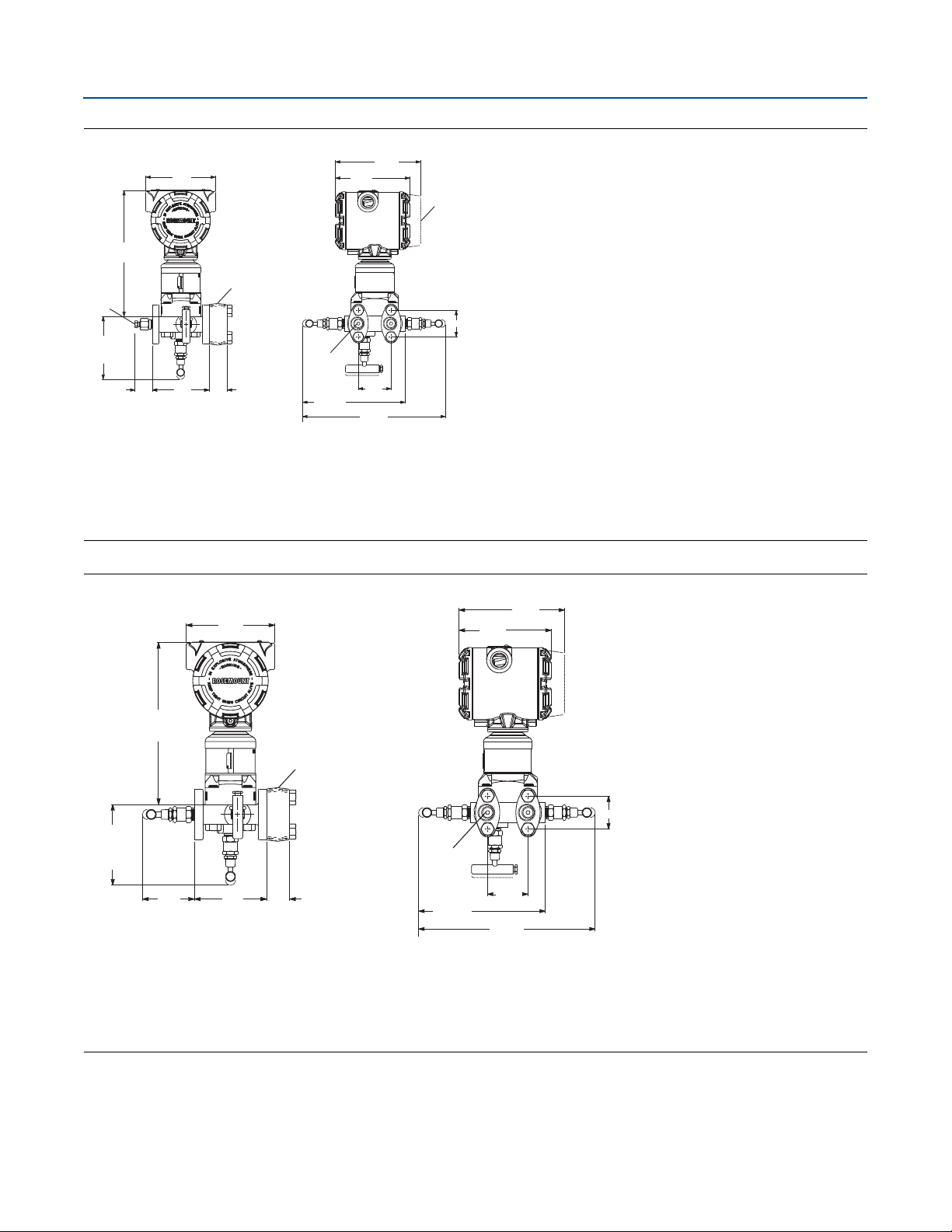
Figure 16. Rosemount 305 Three Valve Traditional DIN Style Manifold
Rosemount Manifolds
A. Drain/vent valve
1
/2–14 NPT on optional process adapter
B.
C. 1/4–18 NPT on traditional manifold for process connections without the use of process adapters
(1)
D. 0.75 (19) clearance for cover removal
Dimensions are in inches (millimeters).
1. Adapters can be rotated to give adapter connection centers of 2.0 (51), 2.125 (54), or 2.25 (57).
Figure 17. Rosemount 305 Three Valve Traditional DIN Style Manifold
4.20
(107)
7.72
(196)
A
4.20
(107)
max open
2.98
(76)
4.13
(105)
1.10
(28)
max open
1
A.
/2–14 NPT on optional process adapter
B. 1/4–18 NPT on traditional manifold for process connections without the use of process adapters
(1)
B
6.46
(164)
max open
Dimensions are in inches (millimeters).
5.17
(131)
4.51
(115)
2.126
(54)
9.02
(230)
max open
1.63
(41)
1. Adapters can be rotated to give adapter connection centers of 2.0 (51), 2.125 (54), or 2.25 (57).
Emerson.com/Rosemount
31
Page 32

Rosemount Manifolds
4.20
(107)
8.29
(210)
3.72
(94)
3.75
(96)
max open
A
∅
January 2019
Rosemount In-line style
(1)
Figure 18. Rosemount R306/306 Pressure Style Manifold (Rosemount 3051S_T Shown)
Block-and-bleed style 2-valve style
4.51
(115)
B
6.25
(159)
max open
A. Bleed screw (unspecified dimension) - not
designed for accessory attachments.
1
/4-in. vent connection–pipe plug supplied with manifold, but not installed at factory (pipe plug supplied loose)
B.
Dimensions are in inches (millimeters).
Rosemount conventional style
C. 1/2–14 NPT female NPT process connection (code BA)
(1)
4.10
(104)
C
(2)(3)
Figure 19. Rosemount 304 Two Valve Flange x NPT Conventional Manifold
Instrument side
A
B
max open
6.10
(155)
2.126
(54)
1.13
(29)
B
4.50
(114)
max open
3.74
(95)
C
Process side
A. 0.281 mounting holes (2)
1
B.
/4-in. NPT test (plugged)
1
C.
/2-in. NPT process connection on 2.125 (54) centers (2)
Dimensions are in inches (millimeters).
1. Manifold handle assembly may vary slightly from image shown. All valve handle assemblies provide the same function and meet all stated drawing dimensions.
2. Manifold valve orientation may vary with respect to transmitter mounting holes.
3. Rosemount R306 in-line manifold only available with two valve style.
32
Emerson.com/Rosemount
Page 33

January 2019
A
B
2.126
(54)
1.13
(29)
6.10
(155)
max open
3.74
(95)
4.50
(114)
max open
B
C
∅
2.126
(54)
1.13
(29)
8.50
(216)
max open
A
B
3.74
(95)
4.50
(114)
max open
C
∅
Rosemount Manifolds
Figure 20. Rosemount 304 Two Valve Flange x Flange Conventional Manifold
Instrument side
Process side
A. 0.281 mounting holes (2)
1
B.
/4-in. NPT test (plugged)
7
C.
/16–20–UNF mounting holes (4) on a 2.125 x 1.625–in. hole pattern
Dimensions are in inches (millimeters).
Figure 21. Rosemount 304 Three Valve Flange x NPT Conventional Manifold
Instrument side
(1)
(1)
Process side
A. 0.281 mounting holes (2)
1
B.
/4-in. NPT test (plugged) (2)
1
C.
/2-in. NPT process connection on 2.125 (54) centers (2)
Dimensions are in inches (millimeters).
1. Manifold handle assembly may vary slightly from image shown. All valve handle assemblies provide the same function and meet all stated drawing dimensions.
Emerson.com/Rosemount
33
Page 34

Rosemount Manifolds
1.13
(29)
8.50
(216)
max open
A
B
2.126
(54)
3.74
(95)
4.50
(114)
max open
C
∅
12.3 (312)
max open
4.0
(102)
A
5.0 (127)
max open
2.5 (64)
C
B
January 2019
Figure 22. Rosemount 304 Three Valve Flange x Flange Conventional Manifold
(1)
Instrument side
Process side
A. 0.281 mounting holes (2)
1
B.
/4-in. NPT test (plugged) (2)
7
C.
/16–20–UNF mounting holes (4) on a 2.125 x 1.625–in. hole pattern
Dimensions are in inches (millimeters).
Figure 23. Rosemount 304 Natural Gas Five Valve Flange x NPT Conventional Manifold with NG Option
A. 1/4-in. NPT test (plugged) (2)
1
B.
/2-in. NPT process connection on 2.125 (54) centers (2)
1
C.
/4-in. NPT vent
Dimensions are in inches (millimeters).
1. Manifold handle assembly may vary slightly from image shown. All valve handle assemblies provide the same function and meet all stated drawing dimensions.
34
Emerson.com/Rosemount
Page 35

January 2019
p
3.74
(114)
4.50
(114)
max open
C
B
D
∅
Rosemount Manifolds
Figure 24. Rosemount 304 Natural Gas Five Valve Conventional Manifold with NG Option
12.3 (312)
max open
2.126
(54)
A
2.5 (64)
4.0
(102)
5.0 (126)
en
max o
A. 1/4-in. NPT test (plugged) (2)
1
B.
/4-in. NPT vent
7
C.
/16–20–UNF mounting holes (4) on a 2.125 x 1.625–in. hole pattern
Dimensions are in inches (millimeters).
Figure 25. Rosemount 304 Natural Gas Five Valve Flange x NPT Conventional Manifold
Instrument side
2.126
(54)
A
B
C
(1)
1.13
8.50
(216)
max open
(29)
Process side
A. 0.281 mounting holes (2)
1
B.
/4-in. NPT test (plugged) (2)
Dimensions are in inches (millimeters).
1. Manifold handle assembly may vary slightly from image shown. All valve handle assemblies provide the same function and meet all stated drawing dimensions.
Emerson.com/Rosemount
1
/2-in. NPT process connection on 2.125 (54) centers (2)
C.
1
D.
/4-in. NPT vent
35
Page 36

Rosemount Manifolds
2.126
(54)
1.13
(29)
8.50
(216)
max open
A
3.74
(95)
B
4.50
(114)
max open
C
D
∅
4.88
(124)
max open
1.25
(32)
January 2019
Figure 26. Rosemount 304RT Natural Gas Five-Valve Flange x Flange Conventional Manifold
Instrument side
Process side
A. 0.281 mounting holes (2)
1
B.
/4-in. NPT test (plugged) (2)
Dimensions are in inches (millimeters).
Figure 27. Rosemount 304RW Three-Valve Wafer Manifold
1
/4-in. NPT vent
C.
7
D.
/16–20–UNF mounting holes (4) on a 2.125 x 1.625–in. hole pattern
(1)
(1)
Instrument side
Process side
A. 3/8–16 UNC mounting holes (2)
1
B.
/2–14 NPT process connection (2)
Dimensions are in inches (millimeters).
9.13
(232)
max open
B
1.50
(38)
A
3.35
(85)
1. Manifold handle assembly may vary slightly from image shown. All valve handle assemblies provide the same function and meet all stated drawing dimensions.
36
Emerson.com/Rosemount
Page 37
January 2019
(24)
7.72
(196)
4.90
(125)
3.54
(90)
A
Rosemount mounting brackets
Rosemount Manifolds
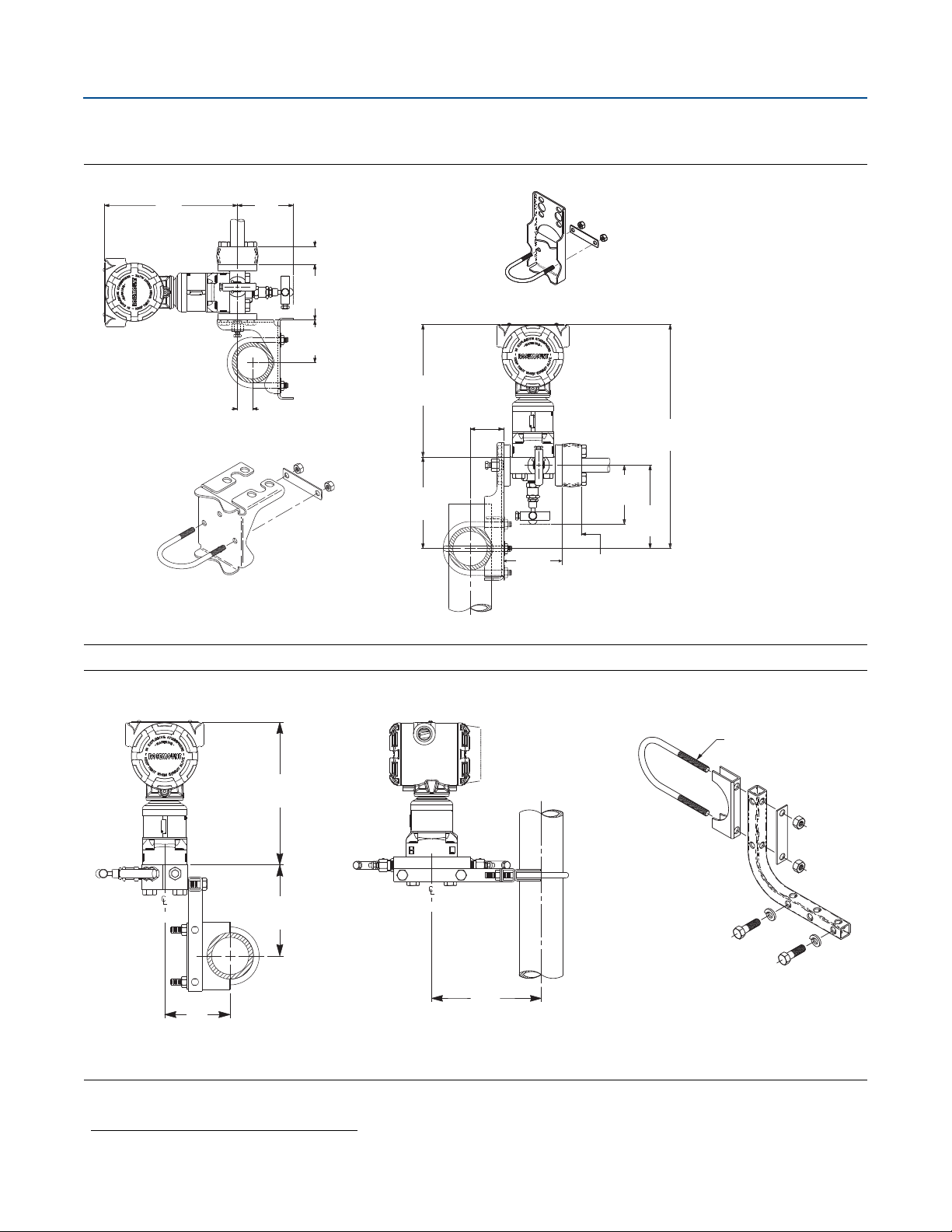
Figure 28. Traditional Manifold with Optional Brackets for 2-in. Pipe Mounting
8.18
(208)
0.93
3.56
(90)
1.10
(28)
3.50
(89)
2.62
(66)
7.72
(196)
B3/B9/BC mounting bracket
1.94
(49.2)
B1/B7/BA mounting bracket
5.32
(135)
3.50
(89)
3.56
(90)
1.10
(28)
(1)
13.03
(331)
4.85
(123)
Dimensions are in inches (millimeters).
Figure 29. Coplanar Manifold with Optional Bracket for 2-in. Pipe Mounting
A. 2-in. U-bolt for pipe mounting
Dimensions are in inches (millimeters).
6.25
(159)
(1)
Option code B4/BE
1. Manifold handle assembly may vary slightly from image shown. All valve handle assemblies provide the same function and meet all stated drawing dimensions.
Emerson.com/Rosemount
37
Page 38

Rosemount Manifolds
5.88
(149)
3.75
(95)
3.40
(86)
1.05
(26.67)
A
4.20
(107)
4.50
(114)
max open
2.75
(70)
B
January 2019
Figure 30. VS/VC Heavy Duty Manifold Mounting Bracket
2-in. pipe mount Panel mount
A. Drain/vent valve
B. 2-in. pipe
Dimensions are in inches (millimeters).
(1)
2.93
(74)
5.88
(149)
1. Manifold handle assembly may vary slightly from image shown. All valve handle assemblies provide the same function and meet all stated drawing dimensions.
38
Emerson.com/Rosemount
Page 39

January 2019
A
17.3
(438)
Rosemount connectors
Rosemount Manifolds
Figure 31. DH Extended Stabilized Connectors for Direct Mounting
(1)(2)
Option code DH
A. Cross section image is shown for dimensioning purposes only; it is not part of the transmitter assembly
Dimensions are in inches (millimeters).
Figure 32. DV Non-Stabilized Connectors for Direct Mounting
(1)(2)
Option code DV
15.2
(385)
A
A. Cross section image is shown for dimensioning purposes only; it is not part of the transmitter assembly
Dimensions are in inches (millimeters).
1. Manifold handle assembly may vary slightly from image shown. All valve handle assemblies provide the same function and meet all stated drawing dimensions.
2. In default assembly orientation, manifold valves will face towards user when module high side is on user's left.
Emerson.com/Rosemount
39
Page 40

Rosemount Manifolds
Options
January 2019
Module guard
A sensor module guard is available to protect the transmitter
process isolating diaphragms. This guard should be used
whenever the transmitter is removed from the integral manifold
to avoid damage to the isolating diaphragms.
Part number: 00305-1000-0001 (5/pack)
P2 cleaning for special services
This option minimizes process contaminants and prepares the
unit for special service by cleaning wetted surfaces and
providing material and packaging considerations per ASTM
G93-96.
SG sour gas
Materials of construction comply with recommendations per
NACE MR0175/ISO 15156 for sour oil field production
environments. Environmental limits apply to certain materials.
Consult latest standard for details. Selected materials also
conform to NACE MR0103/ISO 17495 for sour refining
environments.
ASME B31.1 power piping code
Rosemount Manifolds are available in configurations that meet
the requirements of the ASME B31.1 power piping code. This
code specifies design criteria for most air, gas, steam, water, and
oil systems used in electric generating systems, central and
district heating systems, industrial power plants, and
geothermal plants. ASME B31.1 includes requirements for
manifolds, valves, and piping. Transmitters and other measuring
devices do not fall within the scope of this code.
Marking
Manifolds are tagged with a part number, schematic drawing,
temperature, and pressure limits.
Other publications
For additional information, go to Emerson.com/Rosemount.
CW1 cold temperature
This option provides a –67 °F (–55 °C) manifold temperature
certification for Rosemount 0305 and 0306 manifolds. CW1 can
be paired with BR5 and BR6 options on the Rosemount 3051
pressure transmitter and the BR5 and BR6 options on the
Rosemount 3051S pressure transmitter for a complete cold
temperature solution. Manifold BR6 option (–76 °F [–60°C]) is
available upon request if the temperature requirement of the
application is lower than –67 °F (–55 °C).
Dielectric isolator kits
POM dielectric isolators and PEEK bolt sleeves are available with
the Rosemount 304 5-valve natural gas metering pattern
manifold for added instrument protection. Dielectric kits are
rated to 2500 Vdc and 5 mega-ohms.
Heat block kits
Rosemount 304 Manifolds are available with steam heat block
kits for cold environments and services. The steam block
attaches directly to the manifold to prevent the process from
freezing.
40
Emerson.com/Rosemount
Page 41
January 2019
Rosemount Manifolds
Spare parts list
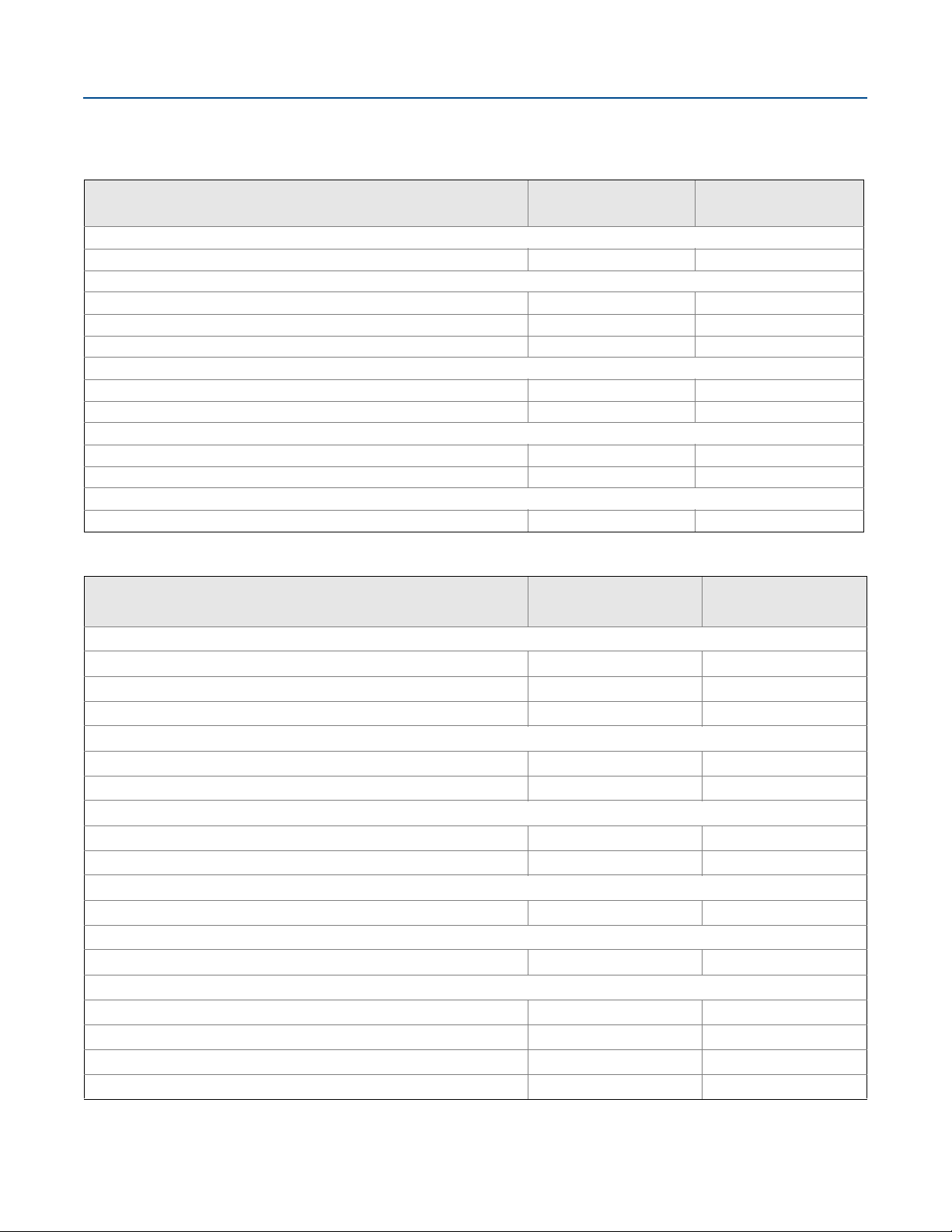
Table 26. Rosemount R305/305 Integral Manifold
Part description
Mounting brackets (qty. 1)
Manifold SST mounting bracket for 2-in pipe mount N/A 00305-0405-0001
Bolt kits (set of 4)
CS bolt kit 03031-0311-0001 03031-0312-0001
SST bolt kit 03031-0311-0002 03031-0312-0002
ANSI/ASTM-A-193-B7M bolt kit 03031-0311-0003 03031-0312-0003
Drain/vents (qty. 1)
316 SST drain/vent for use with 3-valve Rosemount 305 Manifold 01151-0028-0012 01151-0028-0012
Alloy C-276 drain/vent for use with 3-valve Rosemount 305 Manifold 01151-0028-0013 01151-0028-0013
O-rings (set of 12)
Manifold-to-module O-ring, glass-filled PTFE 03031-0234-0001 03031-0234-0001
Manifold-to-module O-ring, graphite-filled PTFE 03031-0234-0002 03031-0234-0002
Sensor guard (set of 5)
Coplanar module sensor guard 00305-1000-0001 00305-1000-0001
Part number
(traditional style)
Part number
(coplanar style)
Table 27. Rosemount 304 Conventional Manifold
Part description
Mounting brackets (qty. 1)
Manifold heavy duty mounting bracket, CS 01166-8005-0002 N/A
Manifold heavy duty mounting bracket, 316 SST 01166-8005-0001 N/A
Manifold SST mounting bracket for 2-in. pipe mount N/A 00305-0405-0001
Coplanar flange kits (qty. 1)
Differential flange kit, SST N/A 00305-1001-0001
Gauge flange kit, SST N/A 00305-1001-1001
O-rings (set of 12)
Manifold-to-flange O-ring, virgin PTFE 03031-0019-0003 03031-0019-0003
Manifold-to-flange O-ring, graphite 03031-1302-0002 03031-1302-0002
Manifold-to-flange bolt kits (set of 4)
Consult factory for part numbers Consult factory Consult factory
Heater block kits (qty. 1)
Steam block kit 00305-0406-0001 N/A
DF adapter kit (qty. 2)
SST adapters, CS bolts, glass-filled PTFE O-rings 03031-1300-0002 N/A
CS adapters, CS bolts, glass-filled PTFE O-rings 03031-1300-0005 N/A
SST adapters, SST bolts, glass-filled PTFE O-rings 03031-1300-0012 N/A
CS adapters, SST bolts, glass-filled PTFE O-rings 03031-1300-0015 N/A
(1)
Part number
(traditional style)
Part number
(wafer style)
Emerson.com/Rosemount
41
Page 42

Rosemount Manifolds
Table 27. Rosemount 304 Conventional Manifold
January 2019
Part description
Socket weld adapter kit (qty. 2)
Part number
(traditional style)
(2)
Part number
(wafer style)
Virgin PTFE O-rings, carbon steel bolts, 316L SST adapter 03031-1320-0002 N/A
Virgin PTFE O-rings, 316 SST bolts, 316L SST adapter 03031-1320-0012 N/A
Graphite O-rings, CS bolts, 316L SST adapter 03031-1320-0102 N/A
Graphite O-rings, 316 SST bolts, 316L SST adapter 03031-1320-0112 N/A
Natural gas connector and dielectric kits (qty. 2)
(3)
Dielectric isolator kit, 316 SST 00304-1100-1022 N/A
Dielectric isolator kit, CS 00304-1100-1122 N/A
Stabilized extended connector kit, dielectric, 316 SST 00304-1100-2000 N/A
Non-stabilized connector kit, dielectric, 316 SST 00304-1100-2010 N/A
Stabilized extended connector kit, dielectric, CS 00304-1100-2101 N/A
Non-stabilized connector kit, dielectric, CS 00304-1100-2111 N/A
Stabilized extended connector kit, PTFE O-rings, 316 SST 00304-1100-3000 N/A
Non-stabilized connector kit, PTFE O-rings, 316 SST 00304-1100-3010 N/A
Stabilized extended connectors kit, PTFE O-rings, CS 00304-1100-3101 N/A
Non-stabilized connector kit, PTFE O-rings, CS 00304-1100-3111 N/A
1. Not available with manifold type code 6.
2. For H2 traditional flange.
3. Only available with manifold type code 6.
42
Emerson.com/Rosemount
Page 43

January 2019
Rosemount Manifolds
Emerson.com/Rosemount
43
Page 44

Rosemount Manifolds
00813-0100-4733, Rev RA
Global Headquarters
Emerson Automation Solutions
6021 Innovation Blvd.
Shakopee, MN 55379, USA
+1 800 999 9307 or +1 952 906 8888
+1 952 949 7001
[email protected]
North America Regional Office
Emerson Automation Solutions
8200 Market Blvd.
Chanhassen, MN 55317, USA
+1 800 999 9307 or +1 952 906 8888
+1 952 949 7001
[email protected]
Latin America Regional Office
Emerson Automation Solutions
1300 Concord Terrace, Suite 400
Sunrise, FL 33323, USA
+1 954 846 5030
+1 954 846 5121
[email protected]
Product Data Sheet
January 2019
Europe Regional Office
Emerson Automation Solutions Europe GmbH
Neuhofstrasse 19a P.O. Box 1046
CH 6340 Baar
Switzerland
+41 (0) 41 768 6111
+41 (0) 41 768 6300
[email protected]
Asia Pacific Regional Office
Emerson Automation Solutions
1 Pandan Crescent
Singapore 128461
+65 6777 8211
+65 6777 0947
[email protected]
Middle East and Africa Regional Office
Emerson Automation Solutions
Emerson FZE P.O. Box 17033
Jebel Ali Free Zone - South 2
Dubai, United Arab Emirates
+971 4 8118100
+971 4 8865465
[email protected]
Linkedin.com/company/Emerson-Automation-Solutions
Twitter.com/Rosemount_News
Facebook.com/Rosemount
Youtube.com/user/RosemountMeasurement
Google.com/+RosemountMeasurement
merson Terms and Conditions of Sale are available upon request.
E
The Emerson logo is a trademark and service mark of Emerson Electric Co.
Rosemount is a mark of one of the Emerson family of companies.
All other marks are the property of their respective owners.
© 2019 Emerson. All rights reserved.
 Loading...