

Page 1

00813-0100-4952, Rev GC
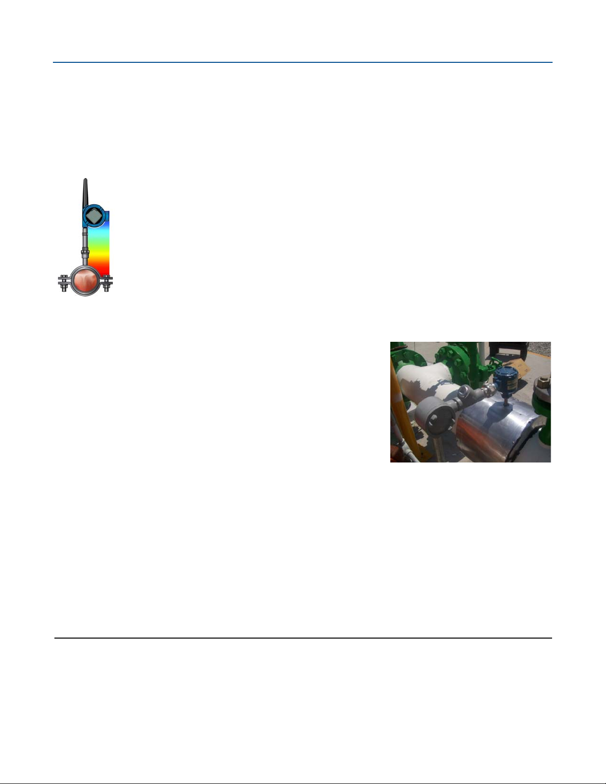
Rosemount™ 0085 Pipe Clamp Sensor
Product Data Sheet
July 2017
Direct mount assembly with Rosemount 3144P Temperature transmitter or Rosemount 648 Wireless
Temperature transmitter with Rosemount X-well
without the requirement of a thermowell or process penetration
Non-intrusive design for fast and easy temperature measurement in piping applications
Platinum RTD temperature sensors with silver or nickel tip
Integrated temperature assemblies provide time and cost savings
™
Technology provides accurate process temperature
Page 2
Rosemount 0085 Pipe Clamp Sensor
Rosemount 0085 Pipe Clamp Sensor
Rosemount X-well Technology provides a Complete Point Solutions™ for accurately measuring process temperature without the requirement of a thermowell or process penetration.
Simplify temperature measurement point specification, installation and maintenance, and eliminate possible
leak points
Calculates a repeatable and accurate process temperature measurement via an in-transmitter thermal
conductivity algorithm
Measures pipe surface and ambient temperature, and utilizes the thermal conductivity properties of the
installation and process piping in order to provide an accurate process measurement
Proven pipe clamp sensors deliver excellent performance and reliability
July 2017
Superior accuracy and stability
Improved response time with silver and nickel tip
Easy implementation and installation in existing application
Available in a wide variety of pipe sizes and material
Installation with only two bolts – no welding needed
Optimized surface contact by spring loaded sensor design
Minimized risk of sensor failure and unplanned shutdowns
Avoids stresses related to flow, pressure, chemical contact, abrasion, vibration, and bending
Maintenance of sensor without shutdown of process
Achieve optimal efficiency with Rosemount wireless transmitter offering
Measure your temperature anywhere
Contents
Ordering information . . . . . . . . . . . . . . . . . . . . . . . . . . . . . 4
How to order Rosemount X-well Technology . . . . . . . . . 8
Overview . . . . . . . . . . . . . . . . . . . . . . . . . . . . . . . . . . . . . . . . 9
Specifications . . . . . . . . . . . . . . . . . . . . . . . . . . . . . . . . . . . 10
2
Dimensional Drawings . . . . . . . . . . . . . . . . . . . . . . . . . . . .11
Accessories . . . . . . . . . . . . . . . . . . . . . . . . . . . . . . . . . . . . . .13
Product Certifications . . . . . . . . . . . . . . . . . . . . . . . . . . . .14
Emerson.com/Rosemount
Page 3

July 2017
Rosemount 0085 Pipe Clamp Sensor
Explore the benefits of Complete Point Solutions from Rosemount Temperature Measurement
An “Assemble to Transmitter” option enables Emerson
temperature solution, delivering an installation-ready transmitter and sensor assembly
Emerson has a complete portfolio of single point, high density and wireless
temperature measurement solutions, allowing you to effectively measure and control
your processes with the reliability you trust from Rosemount products
™
to provide a complete point
Experience global consistency and local support from numerous worldwide Rosemount Temperature sites
Experienced Instrumentation Consultants help select
the right product for any temperature application and
advise on best installation practices
An extensive global network of Emerson service and support
personnel can be on-site when and where they are needed
Emerson.com/Rosemount
3
Page 4

Rosemount 0085 Pipe Clamp Sensor
July 2017
Ordering information
The Rosemount 0085 Pipe Clamp Sensor is designed for fast and easy non-intrusive surface temperature
measurements in piping applications.
Features include:
Temperature range of -50 to 300 °C (-58 to 572 °F) for silver tip, -200 to 300 °C (-328 to 572 °F) for nickel tip
Suitable for pipe sizes
Single or Dual Element Class A Sensor
Assemble to Transmitter Option
Specification and selection of product materials, options, or components must be made by the purchaser of
the equipment.
See page 10 for more information on material selection.
Table 1. Rosemount Pipe Clamp Sensor Ordering Information
The starred offerings (H) represent the most common options and should be selected for best delivery. The non-starred offerings are subject
to additional delivery lead time.
Model Product description
0085 Non Intrusive Pipe Clamp Sensor
Code Connection head IP rating Conduit entry
1
/2-in. to 48-in. (22 mm to 1219 mm)
C Connection head Rosemount, aluminum 68 M20 x 1.5 H
D Connection head Rosemount, aluminum 68
1
/2-in. NPT H
G Connection head Rosemount, stainless steel 68 M20 x 1.5 H
H Connection head Rosemount, stainless steel 68
1
/2-in. NPT H
N No connection head N/A N/A H
1 Connection head Rosemount, aluminum with LCD display cover 68 M20 x 1.5 H
2 Connection head Rosemount, aluminum with LCD display cover 68
1
/2-in. NPT H
3 Connection head Rosemount, stainless steel with LCD display cover 68 M20 x 1.5 H
4 Connection head Rosemount, stainless steel with LCD display cover 68
1
/2-in.NPT H
Sensor connection
3 Spring loaded adapter H
5 Spring loaded adapter with terminal block H
Sensor type Temperature range
P1 RTD, single element, 4-wire, silver tip -50 to 300 °C (-58 to 572 °F) H
P2 RTD, dual element, 3-wire, silver tip -50 to 300 °C (-58 to 572 °F) H
P3 RTD, single element, 4-wire, nickel tip -200 to 300 °C (-328 to 572 °F) H
P4 RTD, dual element, 3-wire, nickel tip -200 to 300 °C (-328 to 572 °F) H
Extension type Head connection
J Nipple -Union None
N No extension (sensor only option) H
Instrument
connection
1
/2-in. NPT Stainless steel H
Material
4
Emerson.com/Rosemount
Page 5

July 2017
Table 1. Rosemount Pipe Clamp Sensor Ordering Information
The starred offerings (H) represent the most common options and should be selected for best delivery. The non-starred offerings are subject
to additional delivery lead time.
Rosemount 0085 Pipe Clamp Sensor
Extension length (N)
0080 80 mm H
0150 150 mm H
XXXX Non standard lengths 200–500 mm (available in 50 mm increments)
Pipe clamp material
N No clamp (sensor only option) H
P ASTM 304 SST (1.4301) H
B Duplex F51 (1.4462)
C Carbon steel (1.0037)
S ASTM 316 SST (1.4401)
Nonstandard pipe
sizes
Millimeters
Clamp/bolt
dimensions
Inner diameter (D)
Standard pipe sizes
(1)
Inches DIN
Min. OD Max. OD
0022 22 mm
0027 27 mm
0030 30 mm N/A DN25 27 31 30 x 5 mm, M10
0034 34 mm 1 DN25 31 35 30 x 5 mm, M10 H
0043 43 mm 11/4 DN32 40 46 30 x 5 mm, M10
0049 49 mm 11/2 DN40 46 50 30 x 5 mm, M10 H
0061 61 mm 2 DN50 58 68 40 x 6 mm, M12 H
0077 77 mm 21/2 DN65 74 86 40 x 6 mm, M12
0089 89 mm 3 DN80 86 96 40 x 6 mm, M12 H
0115 115 mm 4 DN100 112 120 50 x 8 mm, M16 H
0140 140 mm 5 DN135 137 144 50 x 8 mm, M16 H
0159 159 mm N/A DN150 156 162 50 x 8 mm, M16
0169 169 mm 6 DN150 166 172 50 x 8 mm, M16 H
0220 220 mm 8 DN200 217 223 50 x 8 mm, M16 H
0273 273 mm 10 DN250 269 278 60 x 8 mm, M20
0306 306 mm N/A N/A 302 311 60 x 8 mm, M20
0324 324 mm 12 DN300 320 329 60 x 8 mm, M20
0356 356 mm 14 DN350 352 361 60 x 8 mm, M20
0368 368 mm N/A DN350 364 373 60 x 8 mm, M20
0407 407 mm 16 DN400 401 417 70 x 10 mm, M24
0458 458 mm 18 DN450 452 468 70 x 10 mm, M24
0508 508 mm 20 DN500 502 518 70 x 10 mm, M24
0521 521 mm N/A DN500 515 531 70 x 10 mm, M24
1
/2 DN15 19 24 30 x 5 mm, M10 H
3
/4 DN20 24 27 30 x 5 mm, M10 H
Emerson.com/Rosemount
5
Page 6

Rosemount 0085 Pipe Clamp Sensor
Table 1. Rosemount Pipe Clamp Sensor Ordering Information
The starred offerings (H) represent the most common options and should be selected for best delivery. The non-starred offerings are subject
to additional delivery lead time.
0610 610 mm 24 DN600 604 620 70 x 10 mm, M24
0660 660 mm 26 N/A 654 670 70 x 10 mm, M24
0720 720 mm N/A N/A 714 730 70 x 10 mm, M24
0762 762 mm 30 N/A 756 772 70 x 10 mm, M24
0813 813 mm 32 DN790 807 823 70 x 10 mm, M24
0915 915 mm 36 DN900 909 925 70 x 10 mm, M24
1016 1016 mm 40 DN1000 1010 1026 70 x 10 mm, M24
1070 1070 mm 42 N/A 1064 1064 70 x 10 mm, M24
1219 1219 mm 48 N/A 1213 1229 70 x 10 mm, M24
July 2017
Corrosion protection inlay
N None H
A Material NBR
Options (include with selected model number)
316SST material options
M1 316SST Wire-on tag H
M2 316SST Components H
Sensor options
A1 Single element Class A sensor from -50 to 300 °C (-58 to 572 °F) H
(2)
A2
Dual element Class A sensor from -50 to 300 °C (-58 to 572 °F) H
Assemble to option
XA Assemble sensor to specific temperature transmitter H
Cable gland options
G2 Cable gland, Ex d, brass, 7.5–11.9 mm H
G7 Cable gland, M20 x 1.5, Ex e, blue, Polyamide, diam 5–9 mm H
Product certifications
E1 ATEX Flamep roo f H
I1 ATEX Intrinsic Safety H
E7 IECEx Flameproof and Dust H
E5 FM Explosion-Proof H
E6 CSA Explosion-Proof H
EM Technical Regulations Customs Union (EAC) Flameproof H
IM Technical Regulations Customs Union (EAC) Intrinsic Safety H
Cover chain option
G3 Cover chain (only available with Rosemount connection head material codes C, D, G, and H) H
6
Emerson.com/Rosemount
Page 7

July 2017
Table 1. Rosemount Pipe Clamp Sensor Ordering Information
The starred offerings (H) represent the most common options and should be selected for best delivery. The non-starred offerings are subject
to additional delivery lead time.
Rosemount 0085 Pipe Clamp Sensor
Product certifications
LT Special material to meet extended temperature range of -51 °C H
Q8 Material Traceability Certification per EN 10204 3.1B H
Typical pipe clamp model number: 0085 C 3 P 1 J 0080 P 0061 N
Replacement sensor only model
number:
1. When selecting this option in regards to Rosemount X-well Technology, refer to “How to order Rosemount X-well Technology” on page 8.
2. The sensor option code A2 is not available with sensor type P4.
0085 N3 P 1 N 0080 N 0061 N
Emerson.com/Rosemount
7
Page 8

Rosemount 0085 Pipe Clamp Sensor
July 2017
How to order Rosemount X-well Technology
Rosemount X-well Technology is for temperature monitoring applications and is not intended for control or safety applications. It is
available in the Rosemount 3144P Transmitter and 648 Wireless Transmitter in a factory assembled direct mount configuration with
a Rosemount 0085 Pipe Clamp Sensor. It cannot be used in a remote mount configuration. Rosemount X-well Technology will only
work as specified with factory supplied and assembled Rosemount 0085 Sensor silver tipped single element sensor with an 80 mm
extension length. It will not work as specified if used with other sensors.
Tra ns mi tt er
The Rosemount 3144P option code requirements are:
Code Description
D1-D4 Aluminum field mount housing
PT Temperature measurement assembled with Rosemount X-well Technology
A 4-20 mA with digital signal based on HART protocol
XA Sensor specified separately and assembled to transmitter
C1 Custom configuration of date, descriptor, message, and wireless parameters (requires CDS with order)
HR7 Configured for HART Revision 7
The Rosemount 648 Wireless option code requirements are:
Code Description
PT Temperature measurement assembled with Rosemount X-well Technology
XA Sensor specified separately and assembled to transmitter
C1 Custom configuration of date, descriptor, message, and wireless parameters (requires CDS with order)
The Rosemount 0085 Pipe Clamp Sensor option code requirements are:
Code Description
N No connection head
3 Sensor connection
P1 Sensor type
J Extension type
0080 Extension length
XA Assemble sensor to specific temperature transmitter
Rosemount X-well assemblies are available in most Rosemount 0085 Pipe Clamp sensor diameter sizes.
Rosemount 3144P and 0085
3144P D 1A 1 NA M5 PT C1 HR7 XA
0085 N 3 P1 J 0080 C 0169 N XA
Typical model number of the assembly:
Rosemount 648 Wireless and 0085
648 D X 1 D NA WA3 WK1 M5 PT C1 XA
0085 N 3 P1 J 0080 C 0169 N XA
8
Emerson.com/Rosemount
Page 9

July 2017
60
50
40
30
20
10
0
135 160 185 210
815
˚C
process
process
process
temperature
temperature
temperature
235 260 285
Uninsulated distance from the process (mm)
Housing rise above ambient ( ˚C)
540
˚C
250
˚C
Overview
Rosemount 0085 Pipe Clamp Sensor
Rosemount Pipe Clamp overview
Emerson offers a range of RTDs alone, or as integrated
temperature assemblies including Rosemount Temperature
Transmitters and connection heads.
Rosemount Pipe Clamp Platinum RTD Sensors are highly linear
and have a stable resistance versus temperature relationship.
They are used primarily in industrial environments where high
accuracy, durability, and long-term stability are required, and
are designed to meet the most critical parameters of
international standards: DIN EN 60751/IEC 751 1983
incorporating Amendments 1 and 2.
(1)
Rosemount Pipe Clamp Sensors are available in single and dual
element types.
Selecting the extension length for a pipe clamp sensor
A direct mounting configuration allows heat from the process,
aside from ambient temperature variations, to transfer from the
pipe clamp to the transmitter housing. If the expected pipe
surface temperature is near or above the transmitter
specification limits, consider using additional extension length
or a remote mounting configuration to isolate the transmitter.
Figure 1 provides an example of the relationship between
transmitter housing temperature rise and distance from the
process.
Example
The rated ambient temperature specification for the transmitter
is 85 °C. If the maximum ambient temperature is 40 °C and the
temperature to be measured is 540 °C, the maximum allowable
housing temperature rise is the rated temperature specification
limit minus the existing ambient temperature (85 – 40), or
45 °C.
As shown in Figure 1, an uninsulated distance from the process
of 90 mm will result in a housing temperature rise of 22 °C.
Therefore, 100 mm would be the minimum recommended
distance from the process providing a safety factor of about
25 °C. A longer length, such as 150 mm, is desired to reduce
errors caused by transmitter temperature effect, although in
that case the transmitter may require extra support.
Sensor tip material configuration
The pipe clamp sensor tip is constructed from silver or nickel for
better thermal conductivity and to reduce the thermal response
time. The silver tip has a slightly faster response time while the
nickel tip has a larger temperature range, which allows for
cryogenic applications. The silver tip temperature range is -50 to
300 °C (-58 to 572 °F), and the nickel tip temperature range is
-200 to 300 °C (-328 to 572 °F).
Figure 1. Transmitter Housing Temperature Rise vs.
Uninsulated Distance from the Process
1. 100 Ω at 0 °C, α = 0.00385 Ω x °C/Ω.
Emerson.com/Rosemount
9
Page 10

Rosemount 0085 Pipe Clamp Sensor
Black
Red
Red
Green
Blue
Blue
1
2
3
4
5
6
Blue
Red
Red
Blue
Green
Black
Specifications
July 2017
Material selection
Emerson provides a variety of Rosemount product with various
product options and configurations including materials of
construction that can be expected to perform well in a wide
range of applications. The Rosemount product information
presented is intended as a guide for the purchaser to make an
appropriate selection for the application. It is the purchaser’s
sole responsibility to make a careful analysis of all process
parameters (such as all chemical components, temperature,
pressure, flow rate, abrasives, contaminants, etc.), when
specifying product, materials, options and components for the
particular application. Emerson is not in a position to evaluate or
guarantee the compatibility of the process fluid or other process
parameters with the product, options, configuration or
materials of construction selected.
Rosemount Pipe Clamp Platinum RTD
Nominal resistance
In accordance with DIN EN 60751/IEC 751 1983 incorporating
Amendments 1 and 2, the nominal resistance is defined:
100 Ω RTD at 0 °C
α = 0.00385 Ω x °C/Ω., averaged between 0 and 100 °C
Lead wires
PTFE insulated, silver-coated copper wire (Figure 2)
Identification data
The model and serial numbers are engraved directly on the
spring loaded adapter.
Ingress Protection (IP) rating for connection head
IP68 and NEMA® 4X
Figure 2. Sensor Lead Wire Termination - Pipe Clamp RTD
Spring Loaded
Single element 4-wire Dual element 3-wire
Red
Red
White
White
Limit deviations
Tolerance Class B, as standard t = ±(0.3 + 0.005 x [t]);
temperature range -200 to 300 °C (-328 to 572 °F)
Tolerance Class A, as option t = ±(0.15 + 0.002 x [t]);
temperature range -50 to 300 °C (-58 to 572 °F)
Process temperature range
-200 to 300 °C (-328 to 572 °F)
Ambient temperature range
-40 to 85 °C (-40 to 185 °F)
Self-heating
0.15 K/mW when measured as defined in DIN EN 60751; 1996
Insulation resistance (RTD)
1,000 MΩ minimum insulation resistance when measured at
500 V dc at room temperature
Sheath material
321 SST with mineral insulated cable construction and silver or
nickel tip
White
1
6
5
4
White
2
Red
3
Red
10
Emerson.com/Rosemount
Page 11

July 2017
L
11± 2
68 N
D
Dimensional Drawings
Figure 3. 1/2-in. ANPT Spring Loaded Adapter
Rosemount 0085 Pipe Clamp Sensor
Figure 4. Pipe Clamp Sensor Assembly with Rosemount 3144P
Dimensions are in millimeters.
Emerson.com/Rosemount
11
Page 12

Rosemount 0085 Pipe Clamp Sensor
68
N
D
Figure 5. Pipe Clamp Sensor Assembly with Rosemount Connection Head
68 N
July 2017
D
Figure 6. Pipe Clamp Sensor Assembly with Rosemount 648 Wireless Transmitter
Dimensions are in millimeters.
12
Emerson.com/Rosemount
Page 13

July 2017
Rosemount 0085 Pipe Clamp Sensor
Accessories
Table 2. Connection Head
Part number Model/material
IP rating
00644-4410-0011 Rosemount, aluminum 68
00644-4410-0021 Rosemount, aluminum 68 M20 x 1.5
00644-4410-0111 Rosemount, aluminum with LCD display cover 68
00644-4410-0121 Rosemount, aluminum with LCD display cover 68 M20 x 1.5
00644-4411-0011 Rosemount, stainless steel 68
00644-4411-0021 Rosemount, stainless steel 68 M20 x 1.5
00644-4411-0111 Rosemount, stainless steel with LCD display cover 68
00644-4411-0121 Rosemount, stainless steel with LCD display cover 68 M20 x 1.5
Figure 7. Connection Head
With LCD display cover With standard cover
Conduit
connection
1
/2-in. NPT
1
/2-in. NPT
1
/2-in. NPT
1
/2-in. NPT
Process
connection
1
/2-in. NPT
1
/2-in. NPT
1
/2-in. NPT
1
/2-in. NPT
1
/2-in. NPT
1
/2-in. NPT
1
/2-in. NPT
1
/2-in. NPT
A. LCD display
Dimensions are in millimeters.
78
104
A
128
78
128
104
100
Emerson.com/Rosemount
13
Page 14

Rosemount 0085 Pipe Clamp Sensor
Product Certifications
Rev 1.8
July 2017
European Directive Information
A copy of the EU Declaration of Conformity can be found at the
end of the Quick Start Guide. The most recent revision of the EU
Declaration of Conformity can be found at
Emerson.com/Rosemount
.
Ordinary Location Certification
As standard, the transmitter has been examined and tested to
determine that the design meets the basic electrical,
mechanical, and fire protection requirements by a nationally
recognized test laboratory (NRTL) as accredited by the Federal
Occupational Safety and Health Administration (OSHA).
North America
The US National Electrical Code® (NEC) and the Canadian
Electrical Code (CEC) permit the use of Division marked
equipment in Zones and Zone marked equipment in Divisions.
The markings must be suitable for the area classification, gas,
and temperature class. This information is clearly defined in the
respective codes.
North America
E5 FM Explosionproof and Dust-Ignitionproof
Certificate: 0R7A2.AE
Standards: FM Class 3600- 2011, FM Class 3615-2006, FM Class
3810-2005, ANSI/NEMA 250-1991
Markings: XP CL I, DIV 1, GP B, C, D, T6; DIP CL II/III, DIV 1, GP E,
F, G, T6; Type 4X; Installed per 00068-0013;
E6 CSA Explosionproof, Dust-Ignitionproof
Certificate: 1063635
Standards: CAN/CSA C22.2 No. 0-M91, CSA Std. C22.2 No.
25-1966, CSA Std. C22.2 No. 30-M1986, CSA
Std. C22.2 No.94-M91, CSA Std. C22.2 No.
142-M1987, CSA Std. C22.2 No. 213-M1987
Markings: XP Class I Groups B, C, and D; DIP Class II Groups E, F,
G; Class III; Class I Div. 2 Groups A, B, C, D; Class I
Zone 1 Group IIB+H2; Class I Zone 2 Group IIC;
Installed per 00068-0033;
Special Conditions for Safe Use (X):
1. See certificate for ambient temperature range
2. The non-metallic label may store an electrostatic charge
and become a source of ignition in Group III environments
3. Guard the LCD cover against impact energies greater than
4 joules
4. Flameproof joints are not intended for repair
5. A suitable certified Ex d or Ex tb enclosure is required to be
connected to temperature probes with Enclosure option
"N".
6. Care shall be taken by the end user to ensure that the
external surface temperature on the equipment and the
neck of DIN Style Sensor probe does not exceed 130 °C.
7. Non-Standard Paint options may cause risk from
electrostatic discharge. Avoid installations that cause
electrostatic build-up on painted surfaces, and only clean
the painted surfaces with a damp cloth. If paint is ordered
through a special option code, contact the manufacturer
for more information
I1 ATEX Intrinsic Safety
Certificate: Baseefa16ATEX0101X
Standards: EN 60079-0:2012+A11:2013, EN
60079-11:2012
Markings: II 1 G Ex ia IIC T5/T6 Ga SEE CERTIFICATE FOR
SCHEDULE
Thermocouples; Pi = 500mW T6 60 °C ≤ Ta ≤ +70 °C
RTDs; Pi = 192mW T6 60 °C ≤ Ta ≤ +70 °C
RTDs; Pi = 290mW
Special Conditions of Use (X):
1. The equipment must be installed in an enclosure which
affords it a degree of ingress protection of at least IP20
T6 60 °C
T5 60 °C
≤ Ta ≤ +60 °C
≤ Ta ≤ +70 °C
International
E7 IECEx Flameproof
Certificate: IECEx FMG 12.0022X
Standards: IEC60079-0:2011, IEC60079-1:2007
Markings: Ex d IIC T6…T1 Gb
Europe
E1 ATE X Flameproof
Certificate: FM12ATEX0065X
Standards: EN60079-0:2012, EN60079-1:2007
Markings: II 2 G Ex d IIC T6…T1 Gb
14
Emerson.com/Rosemount
Page 15

July 2017
Special Conditions for Safe Use (X):
1. See certificate for ambient temperature range
2. The non-metallic label may store an electrostatic charge
and become a source of ignition in Group III environments
3. Guard the LCD cover against impact energies greater than
4 joules
4. Flameproof joints are not intended for repair
5. A suitable certified Ex d or Ex tb enclosure is required to be
connected to temperature probes with Enclosure option
"N".
6. Care shall be taken by the end user to ensure that the
external surface temperature on the equipment and the
neck of DIN Style Sensor probe does not exceed 130 °C.
7. Non-Standard Paint options may cause risk from
electrostatic discharge. Avoid installations that cause
electrostatic build-up on painted surfaces, and only clean
the painted surfaces with a damp cloth. If paint is ordered
through a special option code, contact the manufacturer
for more information
EAC
EM Explosionproof/ Flameproof
Markings: 1Ex db IIC T6..T1 Gb X; T6 (-50°C to 40°C); T5..T1
(-50°C to 60°C); IP66/IP167
Rosemount 0085 Pipe Clamp Sensor
Special Conditions for Safe Use (X):
1. See Certificate
IM Intrinsic Safety
Markings: 0Ex ia IIC T5/T6 Ga X; T5, Pi = 0.29W, (-60°C to +70°C);
T6, Pi = 0.29W, (-60°C to +60°C); T6, Pi =
0.192W, (-60° to +70°C);
Special Conditions for Safe Use (X):
1. See Certificate
KM Combination of EM, IM, and Dust-Ignitionproof
Markings: Ex tb IIIC T130°C Db X (-60°C to +70°C);
Markings for both EM and IM above are included
with this option.
Special Conditions for Safe Use (X):
1. See Certificate
Emerson.com/Rosemount
15
Page 16

Rosemount 0085 Pipe Clamp Sensor
00813-0100-4952, Rev GC
Global Headquarters
Emerson Automation Solutions
6021 Innovation Blvd.
Shakopee, MN 55379, USA
+1 800 999 9307 or +1 952 906 8888
+1 952 949 7001
RFQ.RMD-RCC@Emerson.com
North America Regional Office
Emerson Automation Solutions
8200 Market Blvd.
Chanhassen, MN 55317, USA
+1 800 999 9307 or +1 952 906 8888
+1 952 949 7001
RMT-NA.RCCRFQ@Emerson.com
Latin America Regional Office
Emerson Automation Solutions
1300 Concord Terrace, Suite 400
Sunrise, FL 33323, USA
+1 954 846 5030
+1 954 846 5121
RFQ.RMD-RCC@Emerson.com
Product Data Sheet
July 2017
Europe Regional Office
Emerson Automation Solutions Europe GmbH
Neuhofstrasse 19a P.O. Box 1046
CH 6340 Baar
Switzerland
+41 (0) 41 768 6111
+41 (0) 41 768 6300
RFQ.RMD-RCC@Emerson.com
Asia Pacific Regional Office
Emerson Automation Solutions Asia Pacific Pte Ltd
1 Pandan Crescent
Singapore 128461
+65 6777 8211
+65 6777 0947
Enquiries@AP.Emerson.com
Middle East and Africa Regional Office
Emerson Automation Solutions
Emerson FZE P.O. Box 17033
Jebel Ali Free Zone - South 2
Dubai, United Arab Emirates
+971 4 8118100
+971 4 8865465
RFQ.RMTMEA@Emerson.com
Linkedin.com/company/Emerson-Automation-Solutions
Twitter.com/Rosemount_News
Facebook.com/Rosemount
Youtube.com/user/RosemountMeasurement
Google.com/+RosemountMeasurement
Standard Terms and Conditions of Sale can be found on the Ter ms a nd
Conditions of Sale page.
The Emerson logo is a trademark and service mark of Emerson Electric
Co.
Complete Point Solution, Rosemount X-well Technology, Rosemount,
and Rosemount logotype are trademarks of Emerson.
National Electrical Code is a registered trademark of National Fire Protection Association, Inc.
NEMA is a registered trademark and service mark of the National Electrical Manufacturers Association.
All other marks are the property of their respective owners.
© 2017 Emerson. All rights reserved.
 Loading...