

Page 1
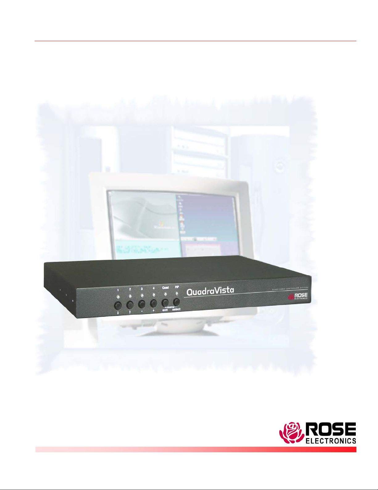
QuadraVista™ QUAD VIDEO KVM SWITCH
INSTALLATION AND OPERATIONS
MANUAL
10707 Stancliff Road Phone (281) 933-7673
Houston, Texas 77099 www.rose.com
Page 2

Page 3

LIMITED WARRANTY
Rose Electronics® warrants the QuadraVista™ to be in good working order for one year from the date of
purchase from Rose Electronics or an authorized dealer. Should this product fail to be in good working
order at any time during this one-year warranty period, Rose Electronics will, at its option, repair or replace
the Unit as set forth below. Repair parts and replacement units will be either reconditioned or new. All
replaced parts become the property of Rose Electronics. This limited warranty does not include service to
repair damage to the Unit resulting from accident, disaster, abuse, or unauthorized modification of the Unit,
including static discharge and power surges.
Limited Warranty service may be obtained by delivering this unit during the one-year warranty period to
Rose Electronics or an authorized repair center providing a proof of purchase date. If this Unit is delivered
by mail, you agree to insure the Unit or assume the risk of loss or damage in transit, to prepay shipping
charges to the warranty service location, and to use the original shipping container or its equivalent. You
must call for a return authorization number first. Under no circumstances will a unit be accepted without a
return authorization number. Contact an authorized repair center or Rose Electronics for further
information.
ALL EXPRESS AND IMPLIED WARRANTIES FOR THIS PRODUCT INCLUDING THE WARRANTIES
OF MERCHANTABILITY AND FITNESS FOR A PARTICULAR PURPOSE, ARE LIMITED IN DURATION
TO A PERIOD OF ONE YEAR FROM THE DATE OF PURCHASE, AND NO WARRANTIES, WHETHER
EXPRESS OR IMPLIED, WILL APPLY AFTER THIS PERIOD. SOME STATES DO NOT ALLOW
LIMITATIONS ON HOW LONG AN IMPLIED WARRANTY LASTS, SO THE ABOVE LIMITATION MAY
NOT APPLY TO YOU.
IF THIS PRODUCT IS NOT IN GOOD WORKING ORDER AS WARRANTIED ABOVE, YOUR SOLE
REMEDY SHALL BE REPLACEMENT OR REPAIR AS PROVIDED ABOVE. IN NO EVENT WILL ROSE
ELECTRONICS BE LIABLE TO YOU FOR ANY DAMAGES INCLUDING ANY LOST PROFITS, LOST
SAVINGS OR OTHER INCIDENTAL OR CONSEQUENTIAL DAMAGES ARISING OUT OF THE USE OF
OR THE INABILITY TO USE SUCH PRODUCT, EVEN IF ROSE ELECTRONICS OR AN AUTHORIZED
DEALER HAS BEEN ADVISED OF THE POSSIBILITY OF SUCH DAMAGES, OR FOR ANY CLAIM BY
ANY OTHER PARTY.
SOME STATES DO NOT ALLOW THE EXCLUSION OR LIMITATION OF INCIDENTAL OR
CONSEQUENTIAL DAMAGES FOR CONSUMER PRODUCTS, SO THE ABOVE MAY NOT APPLY TO
YOU. THIS WARRANTY GIVES YOU SPECIFIC LEGAL RIGHTS AND YOU MAY ALSO HAVE OTHER
RIGHTS WHICH MAY VARY FROM STATE TO STATE.
NOTE: This equipment has been tested and found to comply with the limits for a Class B digital device,
pursuant to Part 15 of the FCC Rules. These limits are designed to provide reasonable protection against
harmful interference when the equipment is operated in a commercial environment. This equipment
generates, uses, and can radiate radio frequency energy and, if not installed and used in accordance with
the instruction manual, may cause harmful interference to radio communications. Operation of this
equipment in a residential area is likely to cause harmful interference in which case the user will be
required to correct the interference at his own expense.
IBM, AT, and PS/2 are trademarks of International Business Machines Corp. Microsoft and Microsoft
Windows are registered trademarks of Microsoft Corp. Any other trademarks mentioned in this manual
are acknowledged to be the property of the trademark owner.
Copyright Rose Electronics 2006. All rights reserved.
No part of this manual may be reproduced, stored in a retrieval system, or transcribed in any form or any means, electronic or mechanical, including photocopying and
recording, without the prior written permission of Rose Electronics.
Rose Electronics Part # MAN-QV
Printed In the United States of America - Revision 2.0
Page 4
DECLARATION OF CONFORMITY
Declaration of Conformity
This equipment generates, uses and can radiate radio frequency energy and if not installed and
used properly, that is in strict accordance with the manufacturer’s instructions may cause
interference to radio communication. It has been tested and found to comply with the limits for a
Class A digital device in accordance with the specifications of Part 15 of FCC rules, which are
designed to provide reasonable protection against such interference when the equipment is
operated in a commercial environment. Operation of this equipment in a residential area is likely
to cause interference, in which case the user at his own expense will be required to take
whatever measures may be necessary to correct the interference.
Changes or modifications not expressly approved by the party responsible for compliance could
void the user’s authority to operate the equipment.
Declaration of Conformity
This declaration is valid for the following product:
Equipment: Video, Keyboard, Mouse Switching System
Type: QuadraVista
Hereby the equipment is confirmed to comply with the requirements set out in the Council
Directive on the Approximation of the Laws of the Member States relating to Electromagnetic
Compatibility (89/336/EEC) and the Council Directive relating to Low Voltage (73/23/EEC).
For the evaluation of the above mentioned Council Directive for Electromagnetic Compatibility
and for Low Voltage, the following standards were consulted:
EN 55022 class A: 1998 + Corrigendum: 2001 + A1:2000 (Emission)
EN 61000-3-2: 2000 (Harmonic current emissions)
EN 61000-3-3: 1995 + Corrigendum: 1997 + A1:2001 (Flicker)
EN 61000-6-2: 2001 (Immunity)
EN 61000-4-2: 1995 + A1:1998 + A2:2001
EN 61000-4-3: 2002
EN 61000-4-4: 1995 + A1:2001 + A2:2001
EN 61000-4-5: 1995 + A1:2001
DIN EN 61000-4-6: 1996 + A1:2001
DIN EN 61000-4-11: 1994 + A1:2001
Page 5

TABLE OF CONTENTS
Contents Page
System Introduction.......................................................................................................................................1
Features.........................................................................................................................................................2
Compatibility ..................................................................................................................................................3
Product Registration ......................................................................................................................................3
Package contents ..........................................................................................................................................3
Rose Electronics web site..............................................................................................................................3
About this manual..........................................................................................................................................3
Installation......................................................................................................................................................5
Installing the KVM station ..........................................................................................................................5
Installing the Computers ............................................................................................................................6
Front Panel LEDs / Push-Button Commands ................................................................................................7
Keyboard Commands ....................................................................................................................................9
On Screen Menu System.............................................................................................................................10
Main Menu ...............................................................................................................................................11
System menu...........................................................................................................................................11
System / HotKey ......................................................................................................................................12
System / HotMouse .................................................................................................................................13
Hotmouse Menu ......................................................................................................................................15
System Quad Mode .................................................................................................................................16
System OSD Position ..............................................................................................................................16
System / OSD Language .........................................................................................................................17
System / Security.....................................................................................................................................17
System / Test Pattern ..............................................................................................................................20
System / Disable Channel .......................................................................................................................21
System / Control ......................................................................................................................................21
MODE..........................................................................................................................................................22
Mode / PiP-Start ......................................................................................................................................22
Configure .....................................................................................................................................................23
Configure / Backup, Recall, Factory Reset..............................................................................................23
Console .......................................................................................................................................................25
Video output / Keyboard / Multi-Monitor / EDID.......................................................................................25
Console / Keyboard .................................................................................................................................26
Console / Multi-Monitor............................................................................................................................27
Console / EDID ........................................................................................................................................28
Video ...........................................................................................................................................................28
Video / Video Input ..................................................................................................................................28
Video / Brightness / Contrast ...................................................................................................................29
Video / Horizontal and Vertical position ...................................................................................................30
Video / Screen width................................................................................................................................31
Video / Phase ..........................................................................................................................................31
Video / Format .........................................................................................................................................32
Computer.....................................................................................................................................................32
Computer / Keyboard...............................................................................................................................33
Computer / Mouse ...................................................................................................................................33
Computer / Reset PS/2............................................................................................................................34
Computer / Change EDID/DDC ...............................................................................................................34
Help .............................................................................................................................................................36
Serial Features ............................................................................................................................................38
Service Information......................................................................................................................................46
Maintenance and Repair..........................................................................................................................46
Technical Support....................................................................................................................................46
Safety ..........................................................................................................................................................47
Safety and EMC Regulatory Statements .................................................................................................48
Page 6

Figures Page
Figure 1. Front View ......................................................................................................................................4
Figure 2. Rear View .......................................................................................................................................4
Figure 3. KVM Installation..............................................................................................................................5
Figure 4. CPU Connect..................................................................................................................................6
Figure 5. Channel select window...................................................................................................................8
Figure 6. HotKey menu................................................................................................................................12
Figure 7. System HotMouse ........................................................................................................................13
Figure 8. System Quad Mode......................................................................................................................16
Figure 9. System / OSD Position .................................................................................................................16
Figure 10. System / OSD Language............................................................................................................17
Figure 11. System / security ........................................................................................................................17
Figure 12. System / Test Pattern .................................................................................................................20
Figure 13. System / Disable Channel ..........................................................................................................21
Figure 14. System / Control .........................................................................................................................21
Figure 15. Mode / PiP-Start .........................................................................................................................23
Figure 16. Backup........................................................................................................................................23
Figure 17. Recall..........................................................................................................................................24
Figure 18. Reset ..........................................................................................................................................24
Figure 19. Console, Video output ................................................................................................................26
Figure 20. Keyboard layout..........................................................................................................................26
Figure 21. Multi-Monitor setup .....................................................................................................................27
Figure 22. EDID display...............................................................................................................................28
Figure 23, Video input..................................................................................................................................28
Figure 24. Video Brightness / Contrast........................................................................................................29
Figure 25, Horizontal Position......................................................................................................................30
Figure 26. Screen width...............................................................................................................................31
Figure 27. Clock phase................................................................................................................................31
Figure 28. Video format ...............................................................................................................................32
Figure 29. Computer....................................................................................................................................32
Figure 30. Computer / Keyboard .................................................................................................................33
Figure 31. Computer / Mouse ......................................................................................................................33
Figure 32. Computer / Reset PS/2...............................................................................................................34
Figure 33. Computer / Change EDID/DDC..................................................................................................34
Figure 34. EDID Programming ....................................................................................................................35
Figure 35. Help / Command.........................................................................................................................36
Figure 36. Help / About................................................................................................................................36
Figure 37. Help / Contact.............................................................................................................................37
Appendices Page
Appendix A. Specifications ..........................................................................................................................49
Appendix B. Parts and cables......................................................................................................................49
Appendix C. Factory Defaults ......................................................................................................................50
Appendix D. Supported Video-In Formats ...................................................................................................51
Page 7
INTRODUCTION
System Introduction
Thank you for choosing the Rose Electronics QuadraVista™. The QuadraVista is the result of
Rose Electronics commitment to providing state-of-the-art KVM switching solutions for today’s
demanding workplace. The QuadraVista has proven to be a valuable investment for any
business or office that has a need to monitor, maintain, or control four or more computers
simultaneously from a common workstation.
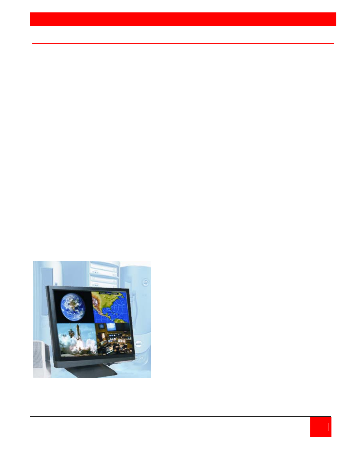
The QuadraVista, Quad Video KVM Switch represents the latest in KVM switching technology. A
user can connect to, display, and control four computers from a single KVM station. To add
additional computers to the system, the QuadraVista can easily connect to additional
QuadraVista’s or interface to a KVM switch and connect to 1,000’s of computers.
The advanced design of the QuadraVista provides four viewing modes; Quad Screen, Dual
screen, Picture-in-Picture (PiP) and Full Screen. Control of a selected computer can be done
while in any of the four modes. View four computers in the quad screen mode and control any
one of them while monitoring, in real time, the other three computers. In the PiP mode you can
view one display on a full screen while monitoring smaller thumbnails of the other three
computers.
The KVM Station can be switched to any computer by simple keyboard commands or using the
on-screen menu system. This makes configuring, monitoring, and computer switching quick and
easy. With a few simple key commands, you can switch to any connected computer, change
views, customize the PiP position and size, set-up security for controlling access to the
QuadraVista, enable or disable selected channels, and much more.
The QuadraVista supports all combinations of both VGA and DVI video cards and monitors.
Each video port on the QuadraVista will automatically be configured for VGA or DVI.
Be more productive, organized and efficient with the dynamic new QuadraVista Quad Video KVM
switch from Rose Electronics.
• View four computers simultaneously in
the quad mode.
• Switch keyboard and mouse control to
any computer while viewing, in real time,
the other three computers.
• The QuadraVista handles analog VGA
and digital DVI video simultaneously.
• All combinations of VGA and DVI video
cards and monitors are supported.
Mixing VGA and DVI monitors and
graphic cards is no problem for the
QuadraVista.
QUADRAVISTA INSTALLATION AND OPERATIONS MANUAL 1
Page 8
Features
J Connect to four computers making each video source viewable and controllable on a single
KVM station
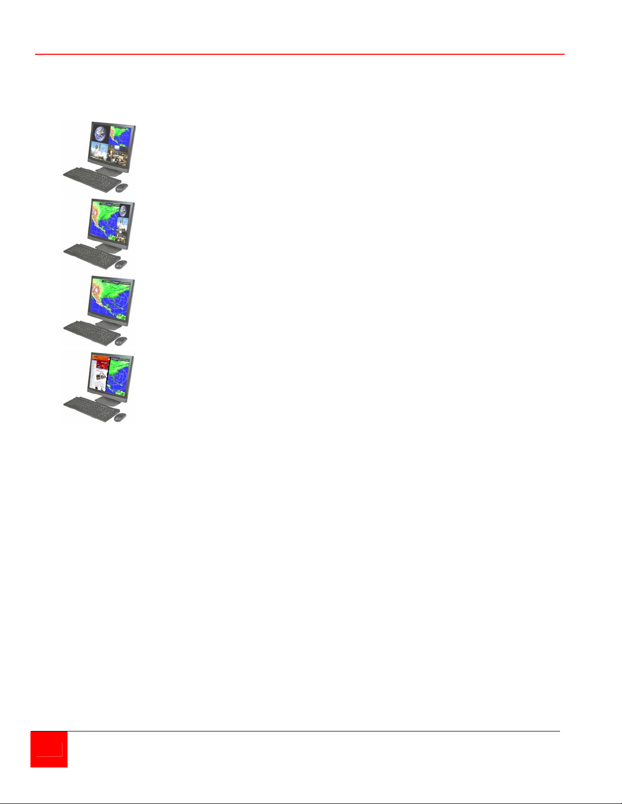
J Four viewing modes; Quad Screen, Picture-in-Picture (PiP), Full Screen, and Dual screen
Quad mode displays four computers
on one screen
PiP mode displays one computer in full
screen with one or three thumbnail
displays of the other computers
Full Screen mode displays the
connected computer’s video full screen
Dual screen mode displays the left half
of the video from two channels
J On-screen menus for easy set-up, console configuration, computer switching, and use
J Crisp, clear, high quality video with resolution up to 1920 x 1200 @ 60Hz
J Automatic or selectable video in and video out resolutions
J Keyboard commands and front panel controls for changing modes and channel selection
J In the Quad mode, switch to and control any of the four screens while monitoring the other
three connections in real time
J VGA and DVI video signals are processed simultaneously
J Supports PS/2 and USB computers (PCs, Sun, Mac)
J Supports digital DVI devices (DVD players, HDTV tuners, etc)
J Two USB ports for keyboard and mouse connections
J Connect to KVM switches to view and control 1,000’s of computers, routers, Ethernet
switches or other serial devices
J Using an XLM-based DCP (Device Control Protocol), the QuadraVista can be controlled
remotely using a serial cable
J Quick and simple to install
J Flash memory technology allows for fast and reliable upgrades
2 QUADRAVISTA INSTALLATION AND OPERATIONS MANUAL
Page 9
Compatibility
Computers PS/2, USB (including SUN and Mac)
Monitors VGA to UXGA / DVI
Keyboards (KVM side) USB
Mouse (KVM side) USB
Keyboard (Computer side) USB, PC1, PC2, or PC3
Mouse (Computer side) USB, PS/2, or PS/2 wheel
Product Registration
Take advantage of the following when you register your Rose Electronics
products online at www.rose.com/htm/warranty.htm:
J Rose Standard Warranty Plus...
J Free Lifetime Firmware Updates
J Free Lifetime Technical Support
J 30 Day Money Back Guarantee
J Priority “First-in-Line” Status for Tech Support
Package contents
The package contents consist of the following:
QuadraVista
Power cord
Rackmount kit
Flash upgrade cable
Installation and operations manual
If the package contents are not correct, contact Rose Electronics or your reseller, so the problem
can be quickly resolved.
Rose Electronics web site
Visit out web site at www.rose.com for additional information on other products that are designed
for data center applications, classroom environments and other applications.
About this manual
This manual covers the installation and operation of QuadraVista.
Disclaimer
While every precaution has been taken in the preparation of this manual, the manufacturer
assumes no responsibility for errors or omissions. Neither does the manufacturer assume any
liability for damages resulting from the use of the information contained herein. The manufacturer
reserves the right to change the specifications, functions, or circuitry of the product without notice.
The manufacturer cannot accept liability for damages due to misuse of the product or other
circumstances outside the manufacturer’s control. The manufacturer will not be responsible for
any loss, damage, or injury arising directly or indirectly from the use of this product.
QUADRAVISTA INSTALLATION AND OPERATIONS MANUAL 3
Page 10
MODELS
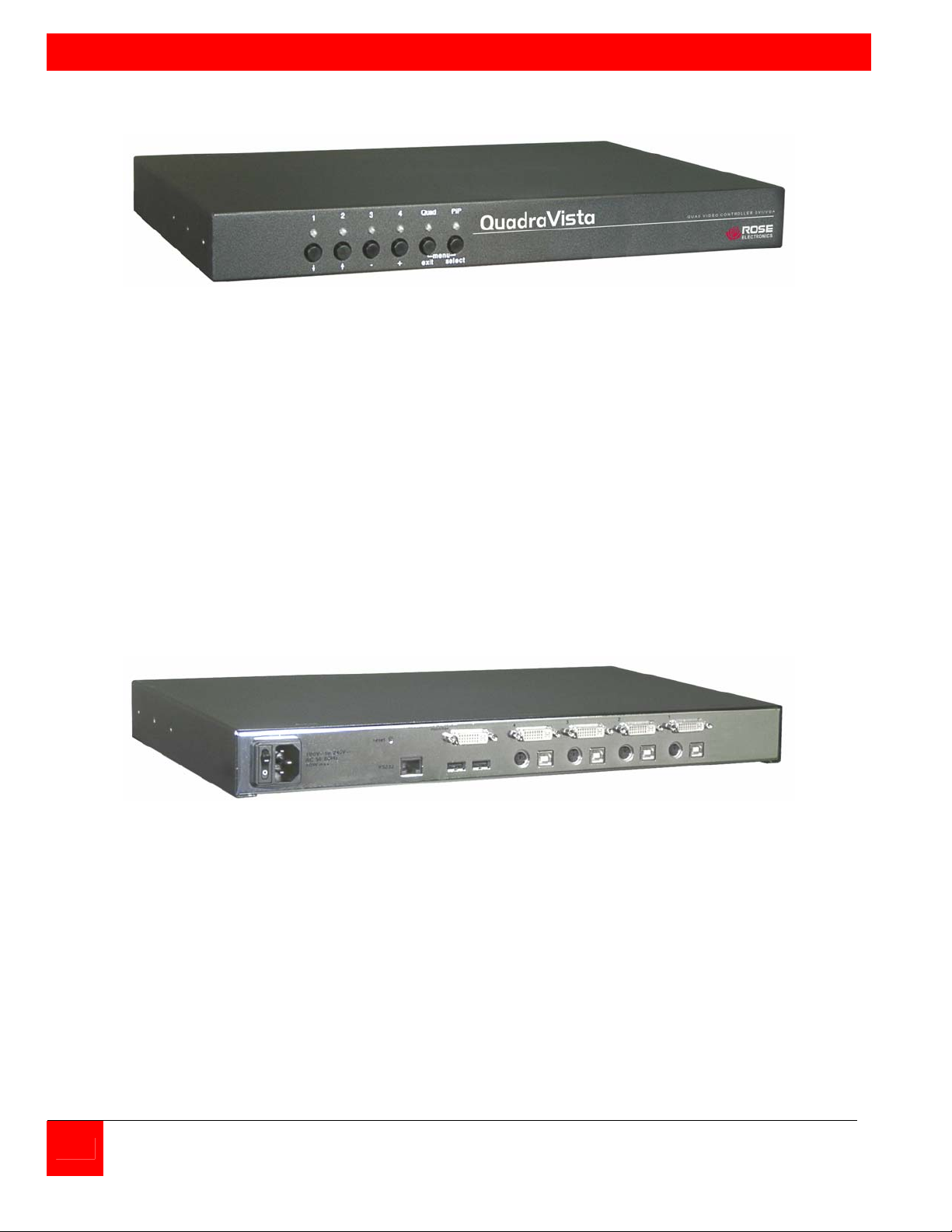
Figure 1. Front View
Selector buttons:
1 – 4 Computer select
Quad Switches to quad screen view
PiP Thumbnails of non-selected inputs
Quad + Pip* Displays the on-screen menu system
1 + 2* Set output resolution to 640 x 480 @ 60Hz
3 + 4** Resets to unit defaults
* buttons pressed simultaneously for longer than 1 second
** buttons pressed simultaneously for longer than 4 seconds
Figure 2. Rear View
Connectors
Power IEC320
Reset Resets unit to factory defaults (video, keyboard, and mouse)
RS232 RJ45 (Flash upgrade port or external device control)
User Station (1) DVI, (2) USB-A
Computers (4) DVI, PS/2 or USB-B
(“Y” adapter required for PS/2 computer connection)
4 QUADRAVISTA INSTALLATION AND OPERATIONS MANUAL
Page 11
INSTALLATION
Installation
Please refer to the safety section first before proceeding with any installation or configuration of
the QuadraVista.
Installation of the QuadraVista consists of connecting the computers and KVM workstation to the
unit. The following steps can be used as a guideline for installing your QuadraVista. It is
recommended that you locate the QuadraVista as close as possible to the computers being
connected.
Installing the KVM station
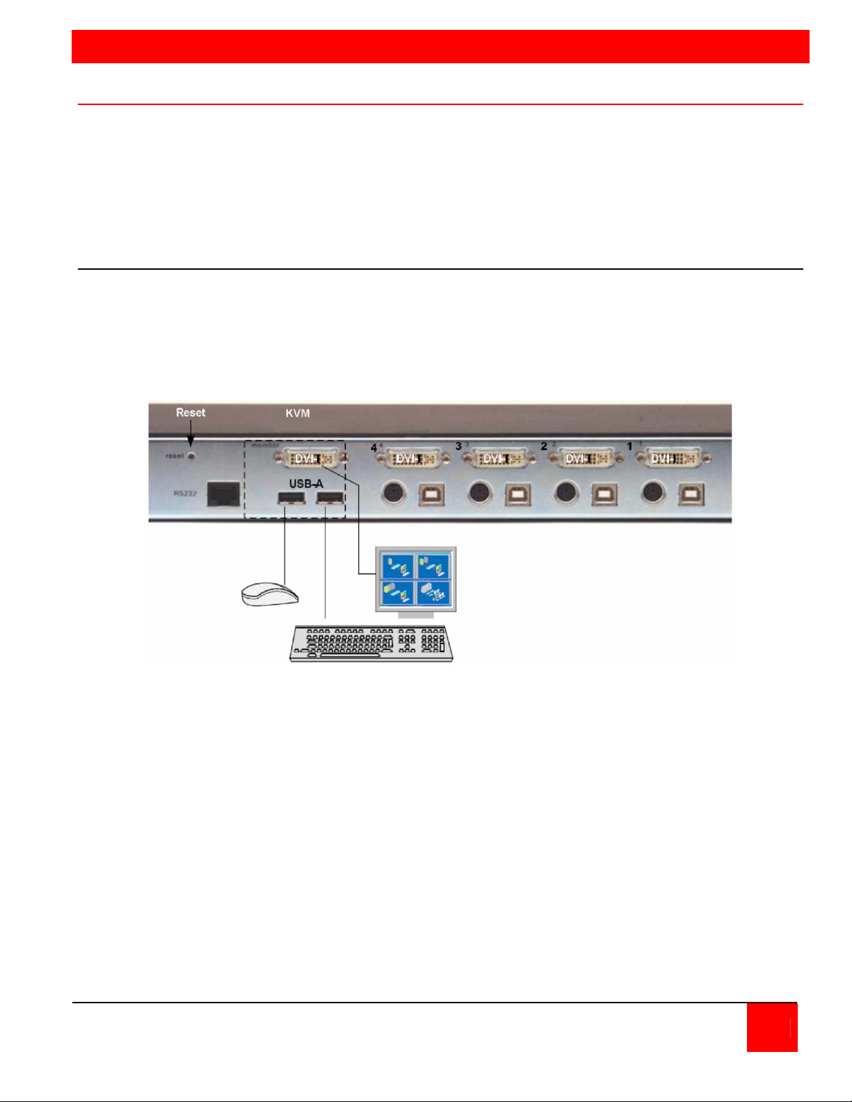
Connect your KVM user station to the QuadraVista as shown in Figure 3. Connect a USB mouse
and USB keyboard to the corresponding USB ports on QuadraVista. If a PS/2 keyboard and
mouse are used, a PS/2 to USB converter must be used.
Next, connect a VGA (HD15F) or DVI monitor to the DVI-I port. If a VGA monitor is used, a VGA
(HD15F) to DVI converter cable must be used.
Figure 3. KVM Installation
QUADRAVISTA INSTALLATION AND OPERATIONS MANUAL 5
Page 12
Installing the Computers
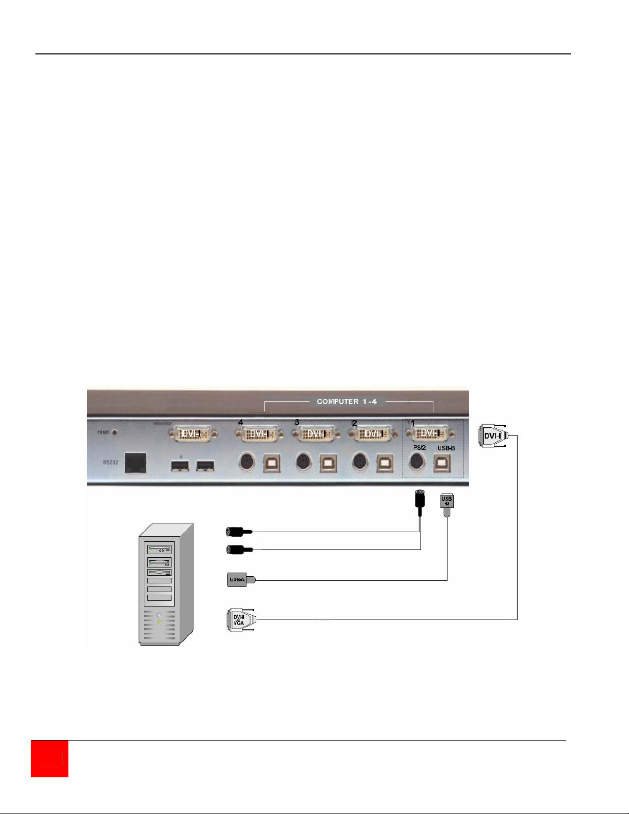
Connect up to four computers to the corresponding video (DVI-I), keyboard/mouse ports on the
QuadraVista as shown in Figure 4. It is recommended that the computers being connected and
QuadraVista be powered off until all cable connections have been made.
Connect a computer's video output port (DVI or VGA) to the QuadraVista's DVI-I connector for
computer #1. If a VGA (HD15F) connector is on the computer, a VGA to DVI cable must be used.
Next connect a USB cable from the computer's keyboard/mouse USB port to the QuadraVista's
USB input port. If the keyboard and mouse ports on the computer are PS/2, use a PS/2 "Y" cable
to connect from the computer's keyboard and mouse PS/2 ports to the PS/2 keyboard/mouse
input port on the QuadraVista.
Connect computer #2, #3, and #4 to the corresponding connectors on the QuadraVista's rear
panel. You are not limited in using the CPU ports to connect to a computer. The CPU port can
also be connected to a Rose KVM switch’s KVM port. This can provide access to as many as
1,000 computers or servers. The DVI video input can accept any analog or digital video signal
from devices like surveillance cameras, a DVD player, or other compatible video sources and
display it on your KVM monitor.
When all cable connections have been made, turn the power on to the QuadraVista and the
computers. All six front panel LEDs will flash momentarily, then the green QUAD led will light
indicating that the unit is ready for operation and the user monitor will display in the Quad mode,
showing all four computers video. If only two video sources are connected, quadrant 3 and 4 will
be blank.
PS/2 “Y” cable
Or
USB cable
DVI to DVI
Or
VGA to DVI cable
Figure 4. CPU Connect
6 QUADRAVISTA INSTALLATION AND OPERATIONS MANUAL
Page 13
COMMANDS
Front Panel LEDs / Push-Button Commands
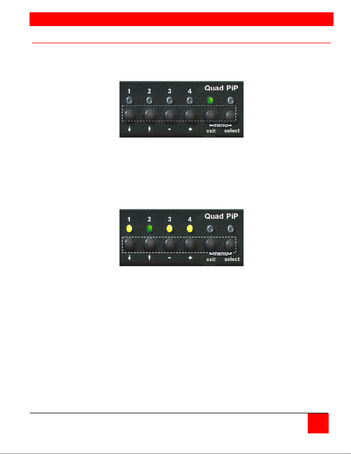
The front panel consists of 6 push buttons and 6 corresponding LEDs. The LEDs provide a visual
representation of what mode the QuadraVista is in, what computer channel is selected, and what
channels are receiving a video signal. The push buttons select a channel, select the quad or pip
mode, and invoke the on-screen-menu system.
LEDs 1-4 indicate which channel is selected. If the LED is green, the corresponding channel is
selected. If the LED blinks green, there is no video signal present on that selected channel. If
the LED is yellow, a video signal is present on that channel but not selected.
The Quad LED lights up green when the system is in the Quad mode. No light and the system is
in the full screen mode.
The PiP LED lights up green when the unit is in the PiP mode. No light when PiP is not selected.
(Note: LEDs 1-4 only indicate video status, not keyboard and mouse)
Channel 2 selected, channels 1, 3, and 4 receiving video
Push buttons 1-4 are used to select a channel and display in full screen, the connected video
source. If your system is in the Quad mode and you press buttons 1, 2, 3, or 4, that channel is
selected and the system automatically switches to full screen mode. Full screen or PiP mode
displays are not affected when a channel is selected.
Pressing the Quad button turns “ON or OFF” the Quad mode.
The PiP button activates different functions depending on what screen mode is active (Full, Quad,
or PiP mode).
In Full screen mode, the PiP button enables or disables the PiP feature.
In the Quad screen mode, pressing the PiP button enables a channel select window (Figure 5 ).
QUADRAVISTA INSTALLATION AND OPERATIONS MANUAL 7
Page 14
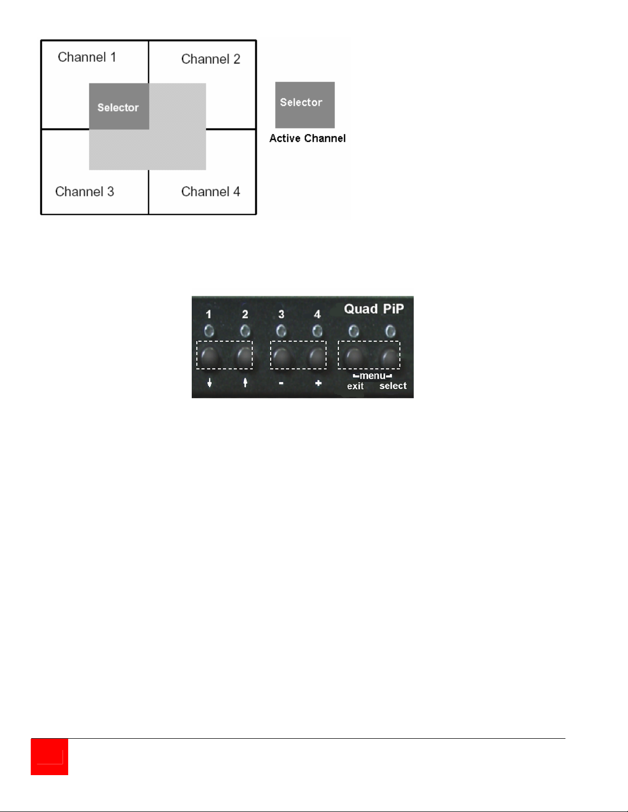
In the Quad mode, the channel
selector window will switch active
channels each time the PiP
button is pressed. The channel
selector window will timeout and
disappear after a preset amount
of non-activity. Timeout value is
configured, from 1-30 seconds,
using the On-Screen-Display.
Figure 5. Channel select window
The front panel push-buttons have additional features as shown below. Simultaneously press and
hold for the designated time to active the feature.
Buttons 1 & 2 set the VGA resolution to 640 x 480
(Press and hold longer than 2 sec)
Buttons 3 & 4 perform a hardware reset for the video, keyboard, and mouse.
(Press and hold longer than 4 sec
Buttons Quad & PiP display the OSD menu.
(Press and hold longer than 1 sec)
For each of the push-button features, there is a corresponding keyboard command that will
perform the same feature. Following are the keyboard commands and their features.
8 QUADRAVISTA INSTALLATION AND OPERATIONS MANUAL
Page 15
Keyboard Commands
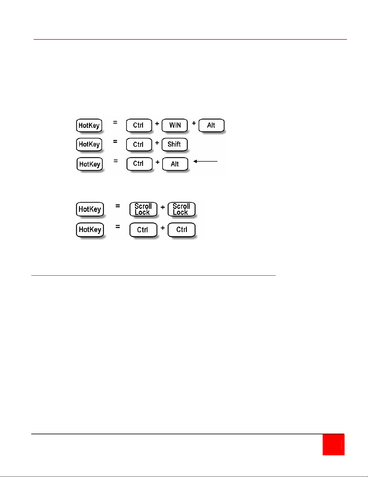
The QuadraVista uses a “HOTKEY” to accept and process a keyboard command. When the
“HOTKEY” command is recognized by QuadraVista, the keyboard commands immediately
following instruct QuadraVista to perform a function, not the connected computer. The default
“HOTKEY” command is left CTRL + Alt keys pressed simultaneously followed by the command.
The “HOTKEY” can be configured using the OSD to a Multiple Key command or a Double Click
command.
The Multiple Key command can be modified from the default keys (left CTRL + ALT) to any
combination of the following keys (1 to 4): left CTRL, SHIFT, ALT, and WINDOWS keys.
Example:
Default HOTKEY
setting
The Double Click (one key, pressed twice = HOTKEY) command can be assigned to the left Ctrl,
Shift, Alt, or the Scroll Lock key.
Example: Press key twice
To execute the following commands, press the assigned HOTKEY then, within 2 seconds
press the command key.
“HK” + Command Description
"HOTKEY" + O Invoke the on-screen menu system
"HOTKEY" + F Change display to full screen mode
"HOTKEY" + P Change display to PIP function
"HOTKEY" + 1 Switch to computer 1 (Full Screen)
"HOTKEY" + 2 Switch to computer 2 (Full Screen)
"HOTKEY" + 3 Switch to computer 3 (Full Screen)
"HOTKEY" + 4 Switch to computer 4 (Full Screen)
"HOTKEY" + Q Change display to quad mode
"HOTKEY" + F1 Switch to quad mode and activate channel 1
"HOTKEY" + F2 Switch to quad mode and activate channel 2
"HOTKEY" + F3 Switch to quad mode and activate channel 3
"HOTKEY" + F4 Switch to quad mode and activate channel 4
"HOTKEY" + I PIP menu
"HOTKEY" + V Reset video resolution to 640 x 480 @ 60Hz
QUADRAVISTA INSTALLATION AND OPERATIONS MANUAL 9
Page 16
ON SCREEN DISPLAY
On Screen Menu System
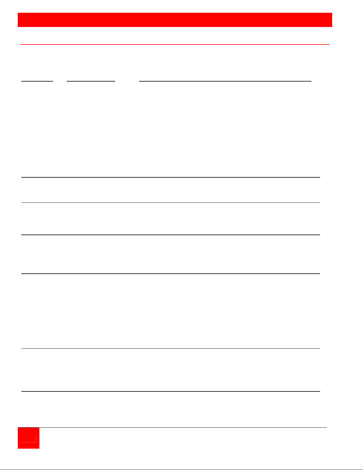
The QuadraVista has an easy to use menu system that enables you to customize the “System”,
“Mode”, “Configuration”, “Console”, “Video”, and “Computers”. Each section is described in detail
on the following pages. The On screen Menu System structure is shown below.
SECTION SUB-SECTION FEATURES .
System Hotkey Multiple Hotkey / Double Click Hotkey
HotMouse HotMouse recognition / timeout
Quad Mode Timeout for channel selection
OSD Position Position of OSD window
OSD Language English / German
Security Set security level (1 – 8)
Test Pattern Cross hairs – Color gradient – Rhombus
Rectangle – Stripes (3) – RGB Convergence –
Manufacturer
Disable Channel Inactivate unused channel(s)
Control Control the QuadraVista externally using the serial port
Mode PiP Size, zoom, position, display mode
Start Set start configuration
Configuration Backup Save current parameters
Recall Restore last saved configuration
Factory Reset Reset to factory default settings
Console Video Output Output resolution (auto or selection)
Keyboard Keyboard layout (English, German)
Multi-Monitor Assigning mouse & keyboard to video
EDID Display EDID data of monitor
Video Video Input Displays video input (DVI, VGA, VGA-DVI, or DVI-VGA)
Brightness Set brightness (analog mode only)
Contrast Set contrast (analog mode only)
Horiz. Position Horizontal screen position
Vert. Position Vertical screen position
Screen Width Set screen width (analog mode only)
Phase Adjust phasing (analog mode only)
Format Fit input format to screen
Computer Keyboard Display keyboard type (PC1, 2, 3, or USB)
Mouse Display mouse type (PS/2, PS/2 wheel, or USB)
Reset PS/2 Resets PS/2 mouse and keyboard
EDID/DDC Program Input EDID
Help Command List of keyboard commands
About Revision level – Firmware / hardware
Contact Contact information
10 QUADRAVISTA INSTALLATION AND OPERATIONS MANUAL
Page 17
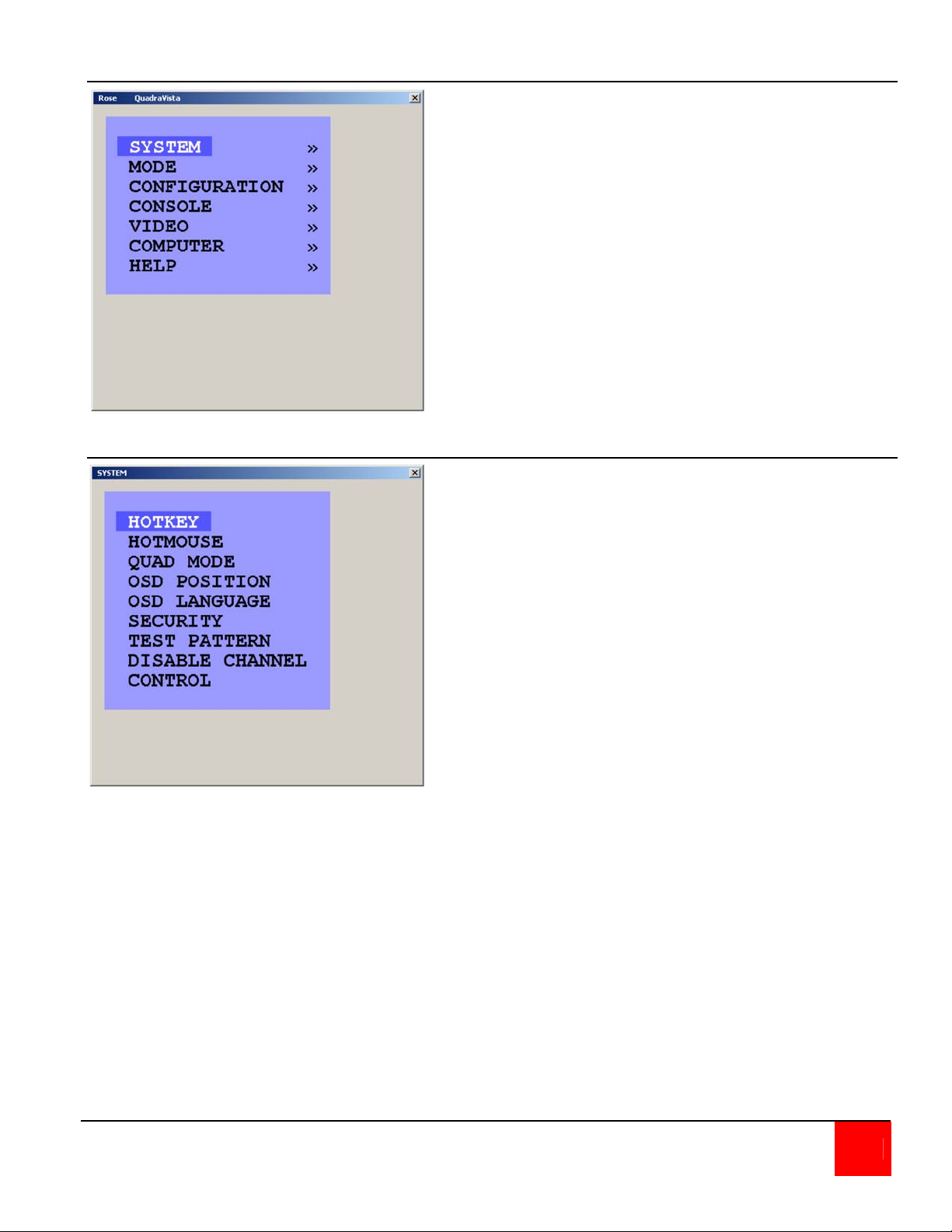
Main Menu
System menu
The Main Menu is called up by
pressing the assigned HotKey + O
(not zero) key. You can also
simultaneously press the Quad and
PiP front panel buttons. This is the
starting point for the OSD menus.
From the main menu you can setup the system, select the start-up
mode, and configure the system
features.
Each OSD menu feature is
described in this section.
The system Menu is called up by
highlighting SYSTEM from the
main menu and pressing enter.
From the system menu you can
set-up the Hotkey, Hotmouse,
Quad Mode, OSD Position,
change OSD languages,
security, display nine different
test patterns to fine tune the
video, disable channels and setup remote control features.
QUADRAVISTA INSTALLATION AND OPERATIONS MANUAL 11
Page 18
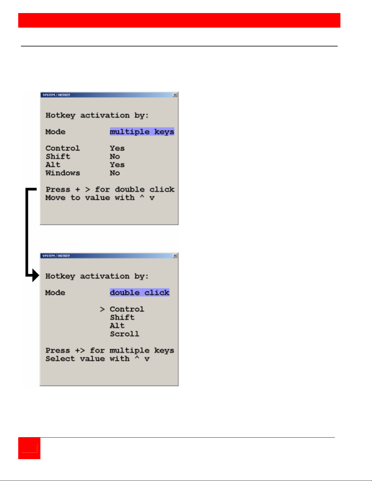
ON SCREEN DISPLAY
System / HotKey
The system HOTKEY window is used to define the multiple keys HOTKEY and Double Click
HOTKEY features. To modify the HOTKEY features, call up the Main menu (Default = left Ctrl +
Alt + O key). From the Main menu, highlight “SYSTEM” and press enter. Highlight “HOTKEY”
and press enter. The SYSTEM / HOTKEY window shown in Figure 6 will display.
From this menu you can modify which
multiple keys and Double Click key
defines the HOTKEY. Use the arrow keys
to navigate through the menu. Select
“Yes” or “No” to choose 1-4 keys for the
HOTKEY.
Press the + key to switch to the double
click menu.
The double click HOTKEY activation
menu allows you to define which key to
double click on to be the HOTKEY.
Use the arrow keys to select one of four
key choices to define the double click
HOTKEY method.
Figure 6. HotKey menu
12 QUADRAVISTA INSTALLATION AND OPERATIONS MANUAL
Page 19
When the multiple key and double click key assignment has been made, exit the menu system
and these values will be saved.
If you assigned the Control, Alt, and Shift keys (menu value = “Yes”) to be the multiple key
HOTKEY, then you must press these three keys simultaneously plus the command key.
If the shift key was assigned to be the double click HOTKEY, then you must press the shift key
twice then the command key.
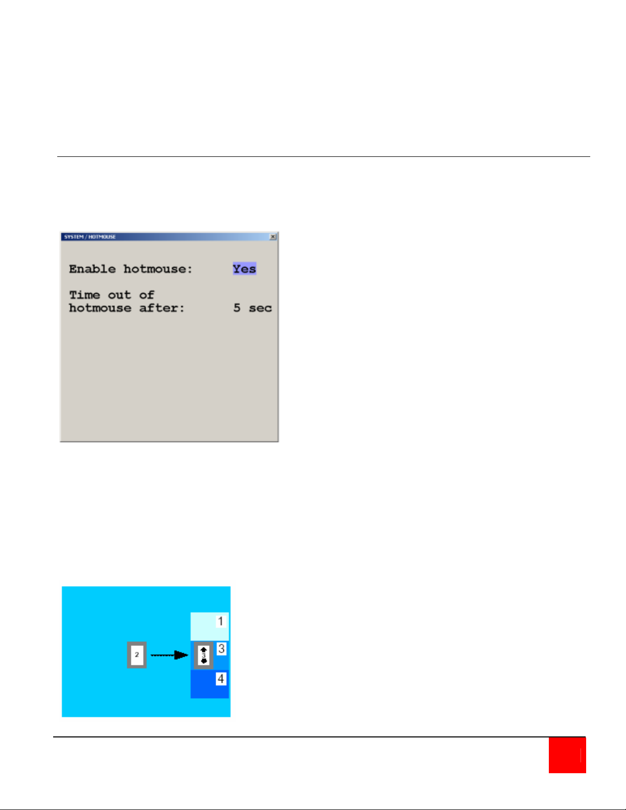
System / HotMouse
The Hotmouse works similarly to the HOTKEY function where an operation is activated using only
the mouse. To use the Hotmouse feature, it first must be enabled. Navigate to the SYSTEM /
Hotmouse window and enable the Hotmouse (set to “Yes”) and set the timeout value (1 to 30
sec.). This determines how long the selection window is displayed.
Enabling the HOTMOUSE feature, you
can perform several functions using only
the mouse:
(Switch channels, size PiP window, and
other features)
Figure 7. System HotMouse
To activate the Hotmouse cursor feature, move the mouse rapidly in alternating horizontal
directions four times (Note: the Hotmouse must be enabled for this feature to function).
→ ← → ← or ← → ← →
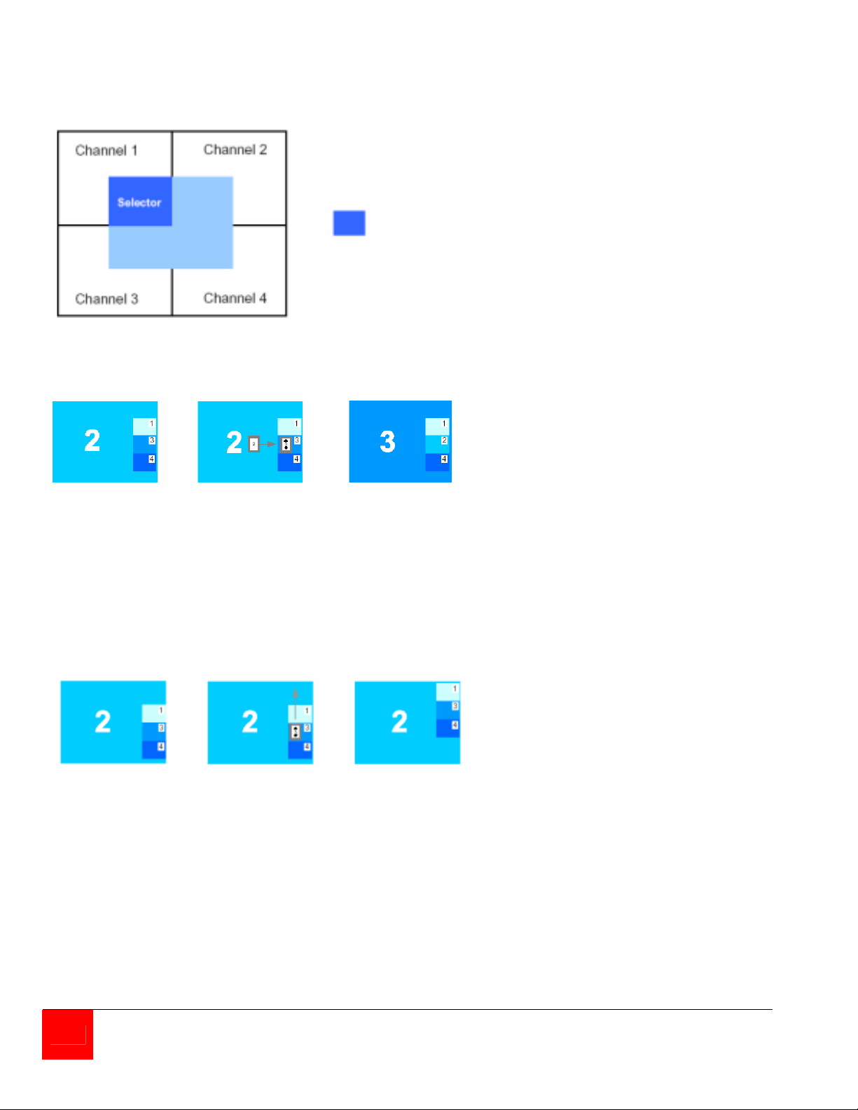
The Hotmouse cursor will change depending on the view mode. Activating the Hotmouse in the
Full screen mode will temporarily display the PiP images of the non-selected channels (see
below). Moving the cursor to a PiP image and clicking on the left mouse button will switch, full
screen, to that channel.
QUADRAVISTA INSTALLATION AND OPERATIONS MANUAL 13
Page 20
A
Activating the Hotmouse in the Quad screen mode will display a box cursor with the active
channel number in the box (see below). Moving the cursor to any quadrant and clicking on the left
mouse button will switch control (keyboard / mouse) to that channel.
ctive channel
Activating the Hotmouse in the PiP mode has three features;
1- Switch active full screen channels
Channel 2 Activate Channel 3
active Hotmouse, active
Move cursor to (Keyboard/
PiP 3 mouse)
Press left mouse
key
2- Move the PiP images vertically
Channel 2 Activate Release mouse
active Hotmouse, key, PiP windows
Move cursor to are in new vertical
PiP windows position
Press/hold left
mouse key, move
PiP windows
vertically
14 QUADRAVISTA INSTALLATION AND OPERATIONS MANUAL
Page 21
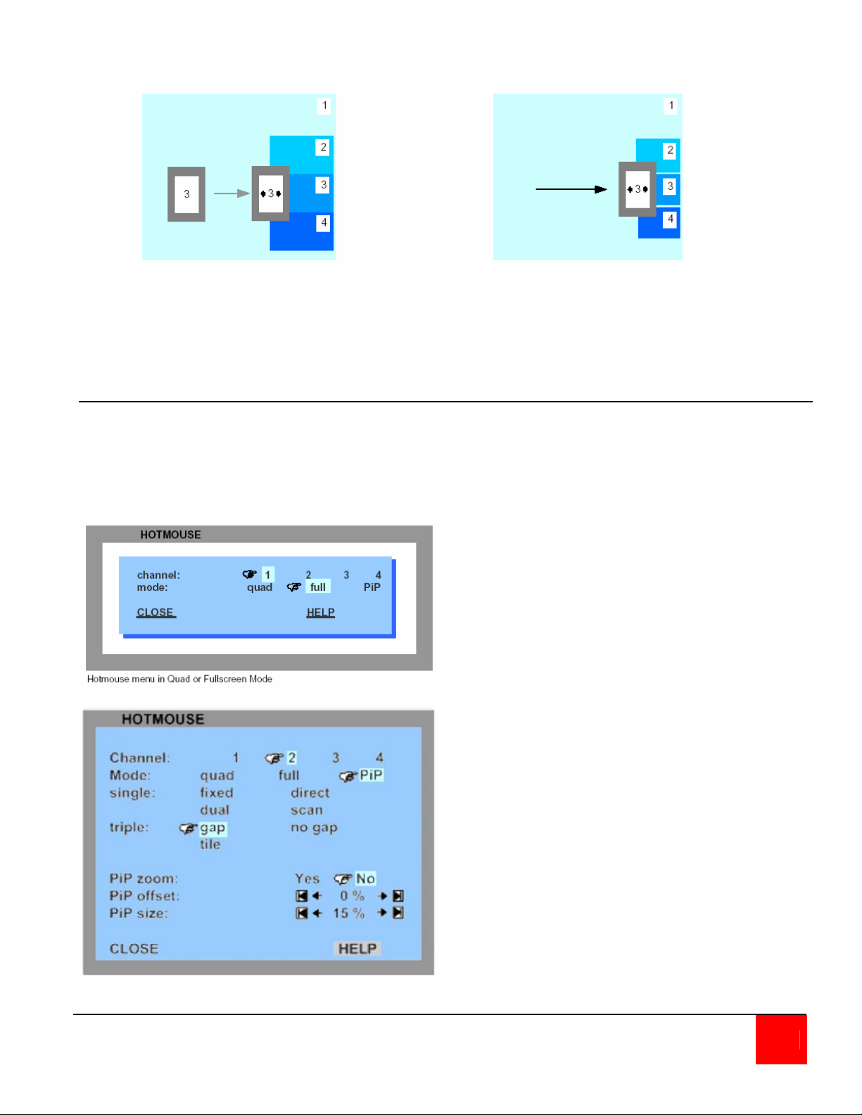
3- Modify the PiP image size
Activate the Hotmouse
and move the cursor to the
left edge of the PiP window.
Press and hold the left mouse button
and drag the PiP window to the left or
right to increase or decrease the PiP
size.
Hotmouse Menu
A menu is associated with the Hotmouse that can be called up to perform various functions based
on what screen mode the system is in. To activate the Hotmouse menu, first activate the
Hotmouse by moving the cursor rapidly to the left and right 4 times. When the Hotmouse cursor
appears, click the right mouse button and depending on the screen mode, the Hotmouse menu
will display.
In the Full screen or Quad mode, the Hotmouse
menu allows you to switch channels, change
display modes (quad, full, PiP, Dual), or
activate a channel.
In the PiP mode the Hotmouse menu allows
you to Switch channels, change the display
mode, change the position, size, and zoom of
the PiP images, change PiP mode (Triple gap,
no gap, tile), and set the scan time.
QUADRAVISTA INSTALLATION AND OPERATIONS MANUAL 15
Page 22
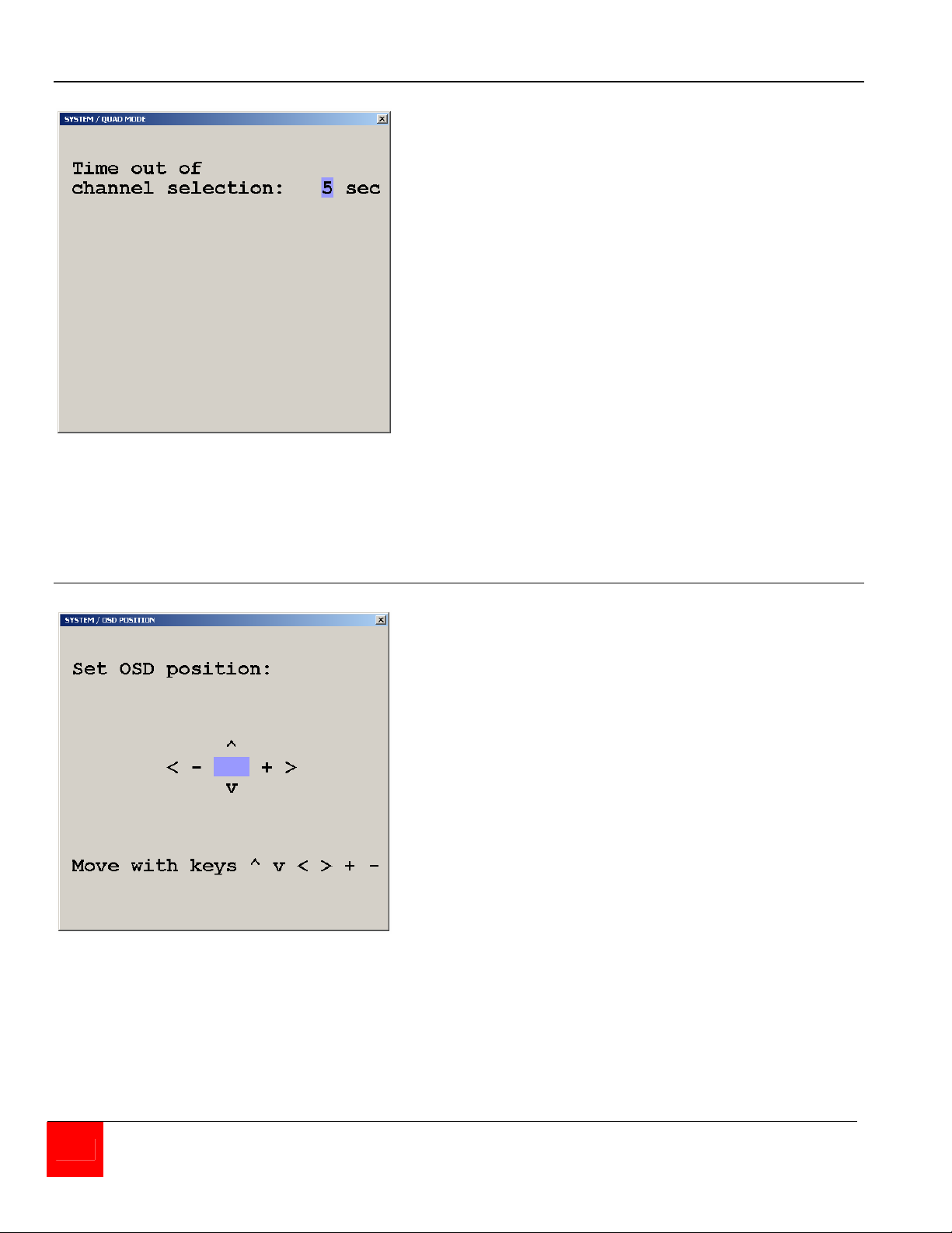
System Quad Mode
Figure 8. System Quad Mode
From the system / quad mode menu you
can set the timeout of the quad selection
window.
System OSD Position
Figure 9. System / OSD Position
Selecting OSD position allows you to set
the screen position of the OSD menus.
Use the arrow keys to move the OSD
screen position
16 QUADRAVISTA INSTALLATION AND OPERATIONS MANUAL
Page 23
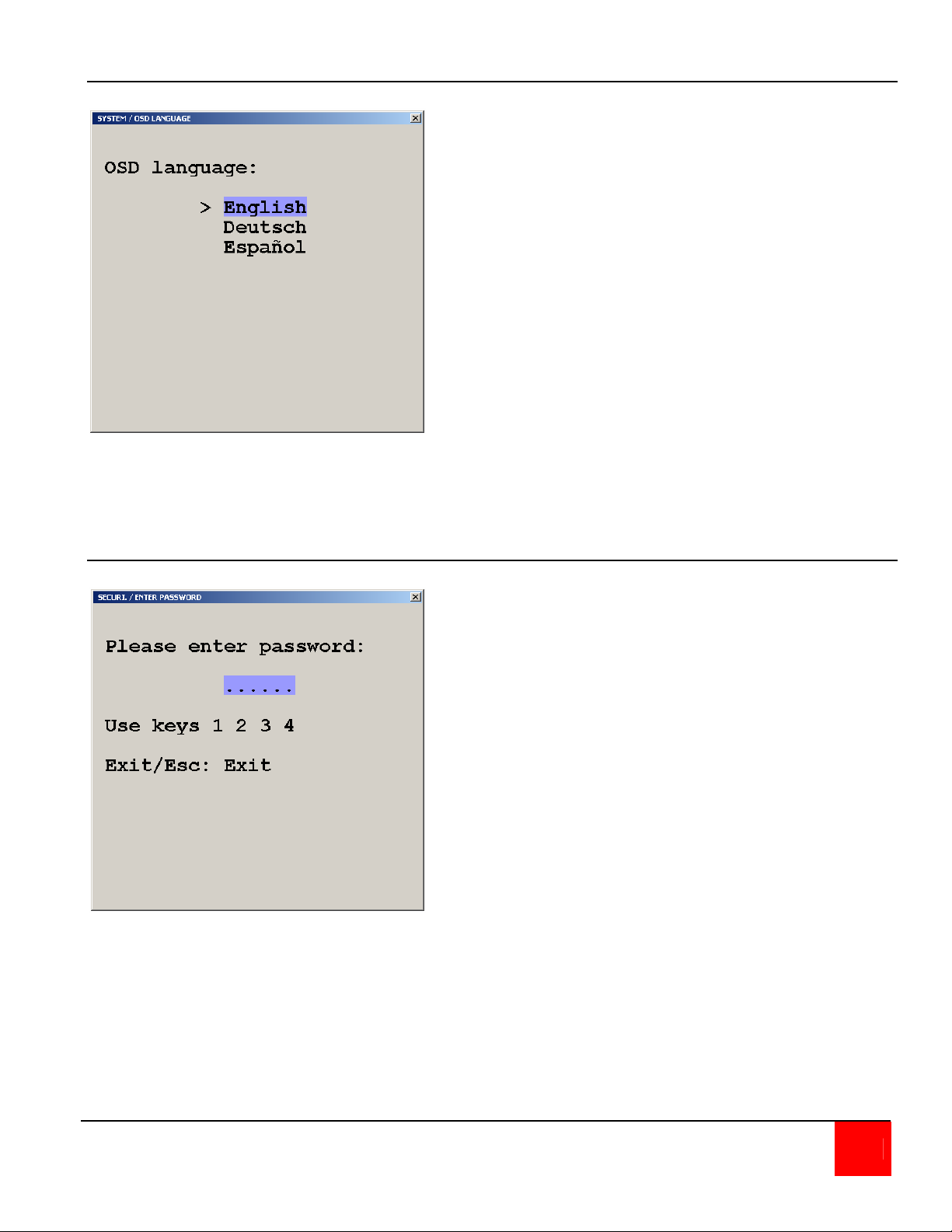
System / OSD Language
Figure 10. System / OSD Language
Selecting OSD Language from the
System menu allows you to change the
language from English, Deutsch, or
Spanish. Use the up / down arrow keys to
select the desired language.
System / Security
Selecting the Security feature
displays the password screen. Enter
the predefined password and the
security window will display. Select
the security level (1 – 8). These
levels are defined below.
Figure 11. System / security
Following lists the security level and functions each level can access. Level 1 security can
perform all functions. Level 0 is the factory security setting which enables all functions.
QUADRAVISTA INSTALLATION AND OPERATIONS MANUAL 17
Page 24
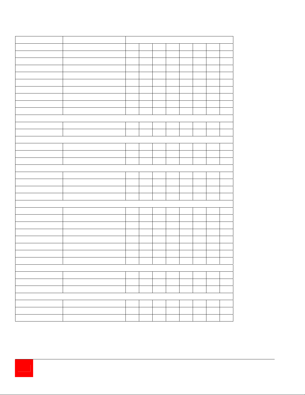
QuadraVista OSD security matrix
Menu Sub-Menu Security Level
1 2 3 4 5 6 7 8
System Hotkey
HotMouse
Quad Mode
OSD Position
OSD Language
Security
Test Pattern
Disable Channel
Control
Mode PiP
Start
Configuration Backup
Recall
Factory Reset
Console Video Output
Keyboard
Multi-Monitor y
EDID
Video Video Input
Brightness
Contrast
Horiz. Position
Vert. Position
Screen Width
Phase
Format
Computer Keyboard
Mouse
Reset PS/2 y
Help Command
About
Contact
y = Authorization to this OSD function is permitted
Security level 0 is the factory default setting. All settings are allowed and all functions enabled
y y
y y
y y
y y y y
y y y
y y y y y y y y
y y y y y
y
y y y y y y y
y y y y
y y y y
y y y y
y y y y y y y
y y
y y y y y y y
y y y y y y y
y y y
y y y
y y y
y y y
y y y
y y y
y y y y
y y y y y y y
y y y y y y y
y y y y y y y
y y y y y y y
y y y y y y y
18 QUADRAVISTA INSTALLATION AND OPERATIONS MANUAL
Page 25

Additional security features are listed below for each security level. These features are in
addition to the OSD security levels listed above.
Security level 8 (most limited level) allows you to work only on pre-selected channel (computer)
in a predefined display mode (Quad / Full / PiP). Except the security menu, where you can
change the security level there are no other operations available.
Security level 7 is the same as security level 8. All OSD windows are available that have
information contents only (showing display modes, active channels and settings):
Security level 6 is the same as security level 7 with the addition of:
Active channel setting using front panel, keyboard, or mouse commands
Channel selection in Quad Mode using front panel PiP button
Security level 5 is the same as security level 6 with the addition of:
- Display mode setting (Quad / Full / PiP) using front panel buttons,
- keyboard or mouse commands
Security level 4 is the same as security level 5 with the following OSD additions:
- Modify PiP settings using HotMouse menu
- System - OSD Position
- Mode - PiP / Start features
- Configuration - Recall
- Video - format
Security level 3 is the same as security level 4 with the following OSD additions:
- System – OSD language
- Video – All video OSD features
Security level 2 is the same as security level 3 with the following OSD additions:
- System – Hotkey / Hotmouse / Quad Mode
- Console - keyboard
Security level 1 is the same as security level 2 with the additions of:
- Set video output to VGA using keyboard command (Hotkey V) or front panel buttons 1+2
- System – Disable channel
- Console – Multi-Monitor / Video output
- Computer – Mouse / Reset PS/2
- Video – Video input
QUADRAVISTA INSTALLATION AND OPERATIONS MANUAL 19
Page 26
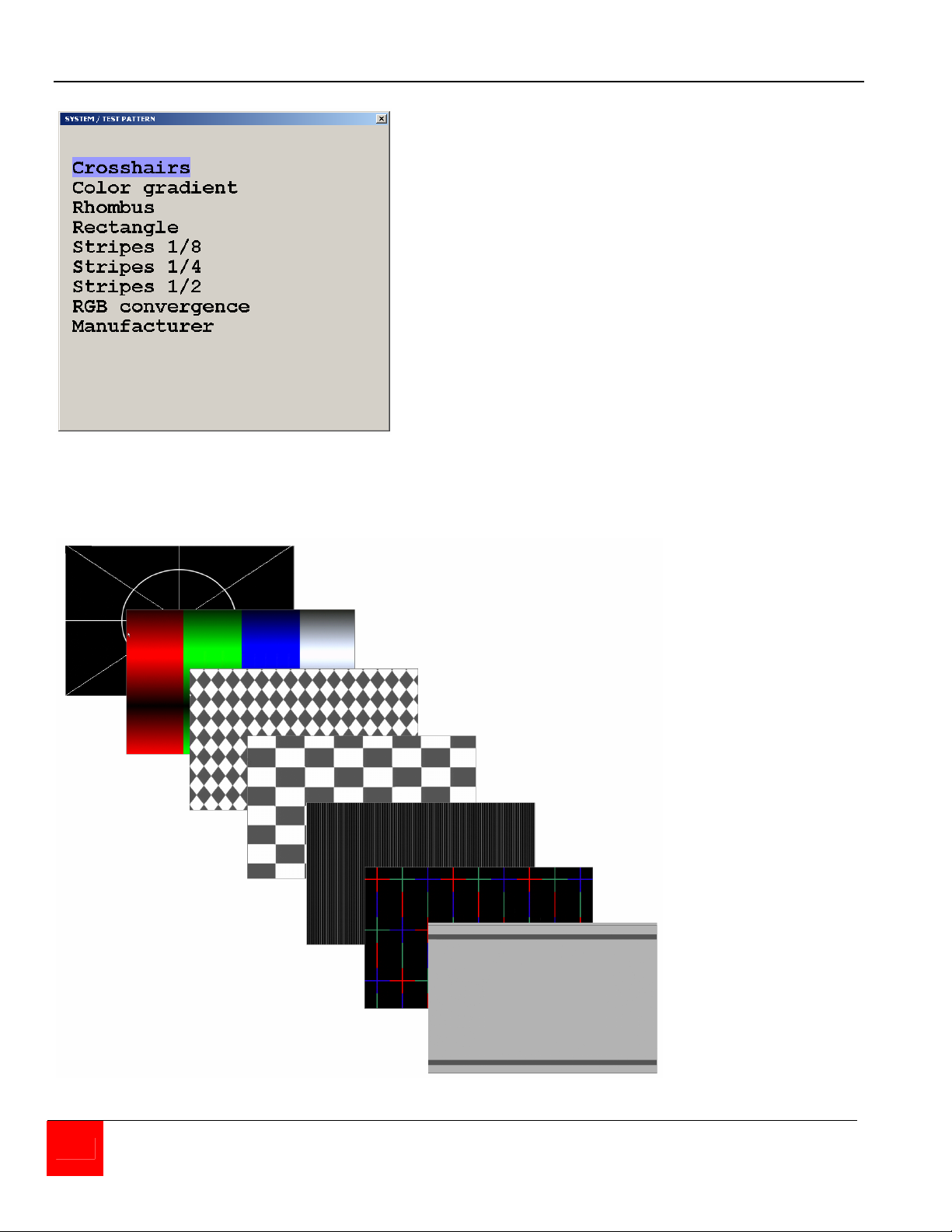
System / Test Pattern
Use the Test Pattern to check the
function of internal video circuits or
to check the quality of the connected
console monitor. It’s recommended
to use all the test patterns for the test
procedure.
Figure 12. System / Test Pattern
There are nine test patterns to assist in adjusting the colors and skew.
CROSSHAIRS
COLOR GRADIENT
RHOMBUS
RECTANGLE
STRIPES (3)
RGB CONVERGENCE
MANUFACTURER
20 QUADRAVISTA INSTALLATION AND OPERATIONS MANUAL
Page 27
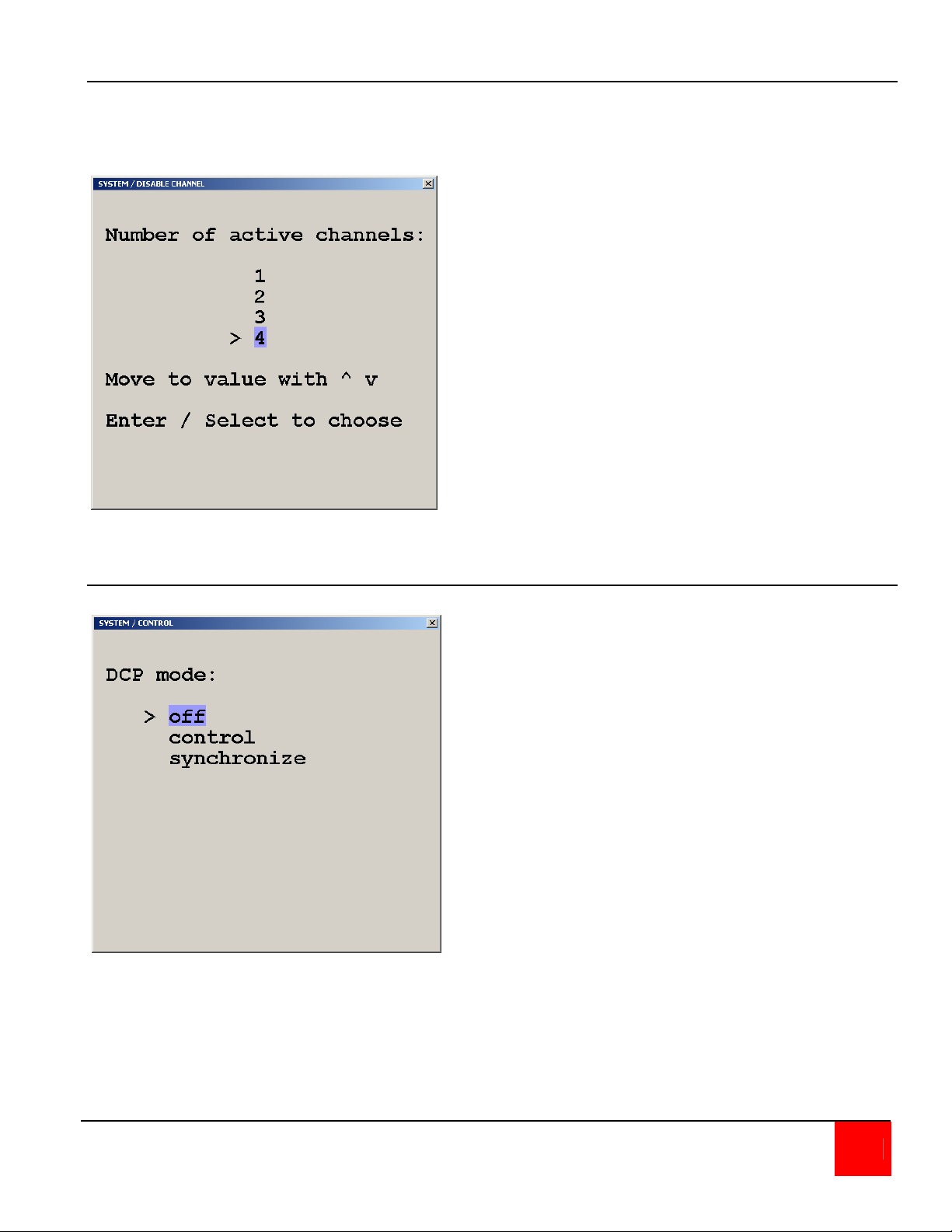
System / Disable Channel
Using this feature, the connected computers should be connected to the channel ports in
ascending order. Connecting computers to channel 1, 2, and 4 and selecting the number of
channels to be 3, channel 4 can not be displayed.
Use the Disable Channel function to
select the number of channels to
display. If computers are connected
to channel 1, 2, and 3, then select 3.
Figure 13. System / Disable Channel
System / Control
The system / control feature allows
setting up of the QuadraVista from a
computer or external device connected
to the serial port.
Selecting control allows external
control of the OSD.
Selecting synchronize will keep
cascaded QuadraVista units in the
same video mode.
See the Serial Operations Section.
Figure 14. System / Control
The DCP (Device Control Protocol) offers three modes, off, control and synchronize. Set the
DCP mode to “Control” if a single QuadraVista will be controlled from an external computer. Set
the mode to “Synchronize” if you system features several linked QuadraVista’s. When in this
mode the QuadraVista status is transmitted to the external computer. For local unit operation, set
the mode to off. See the Serial Operations section for detailed information on the DCP mode.
QUADRAVISTA INSTALLATION AND OPERATIONS MANUAL 21
Page 28
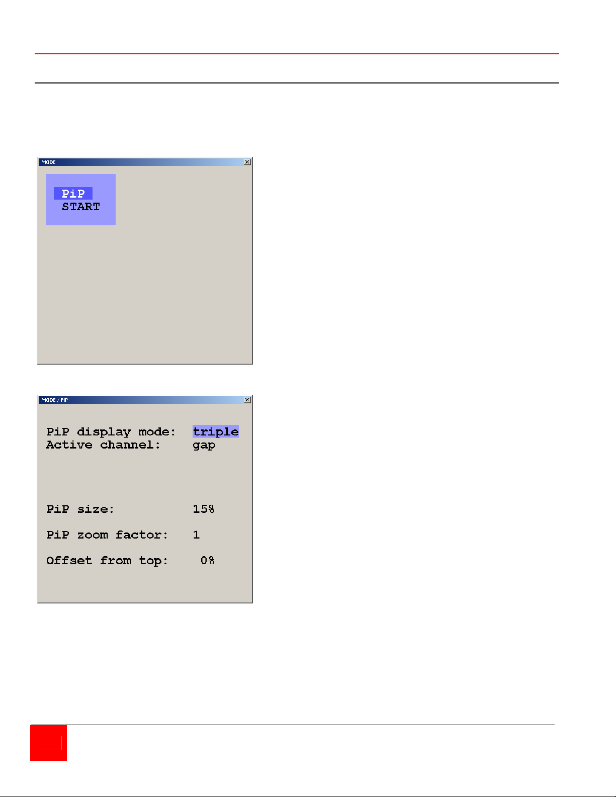
MODE
Mode / PiP-Start
Selecting “MODE” and pressing enter displays the mode screen. Two mode selections are
available, PiP and Start. The PiP features and configuration can be set-up, and the channel and
mode setting on start-up.
The PiP menu allows you to change
from triple to single PiP. Triple display
shows the three non-active windows
on the right of the screen. Single
display shows only one non-active
window. PiP size, zoom, and offset
from the top of the screen can be set.
PiP display modes:
Triple – Displays the three non-active
channels
Single – Displays one non-active channel
Fixed – Permanently displays one
non-active channel
Scan – Scans non-active channels in
one PiP window (scan time
1-9 sec)
Direct – Permanently displays one
non-active channel. Select
the desired channel to
display directly.
22 QUADRAVISTA INSTALLATION AND OPERATIONS MANUAL
Page 29
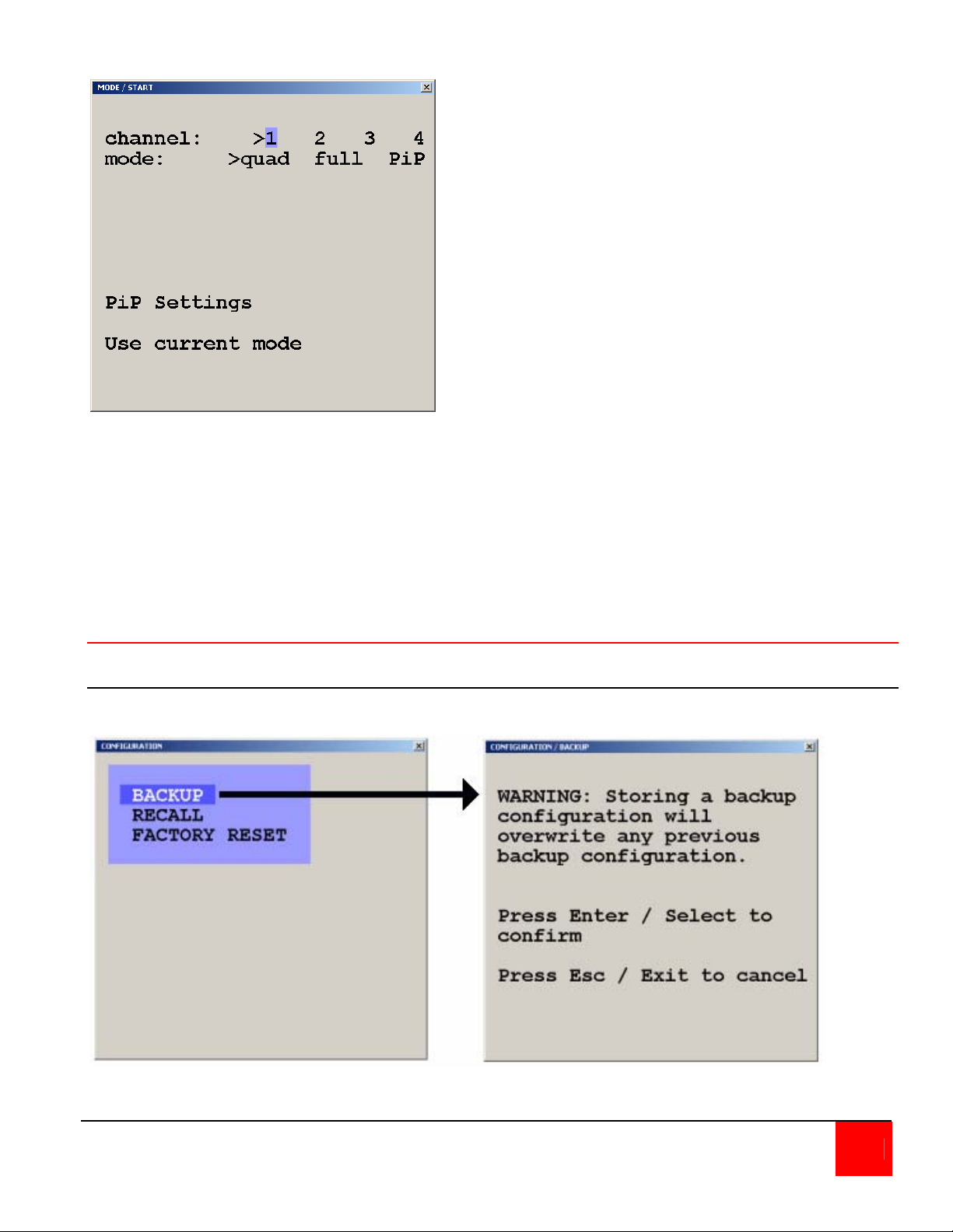
Figure 15. Mode / PiP-Start
Selecting Start from the MODE menu
defines which channel is active, the
display mode, and the PiP settings
when power is applied.
Configure
Configure / Backup, Recall, Factory Reset
The backup command saves the current device settings.
Figure 16. Backup
QUADRAVISTA INSTALLATION AND OPERATIONS MANUAL 23
Page 30
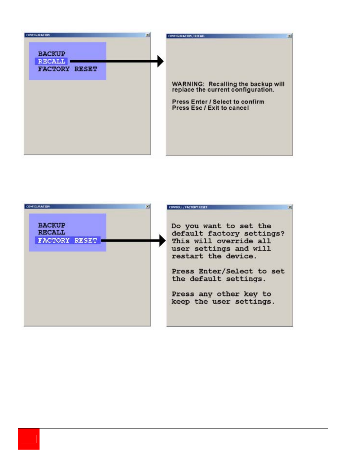
The recall command replaces the current settings with the latest backup.
Figure 17. Recall
The Factory Reset command resets the unit to the original factory settings
See Appendix C. for factory reset values.
Figure 18. Reset
24 QUADRAVISTA INSTALLATION AND OPERATIONS MANUAL
Page 31
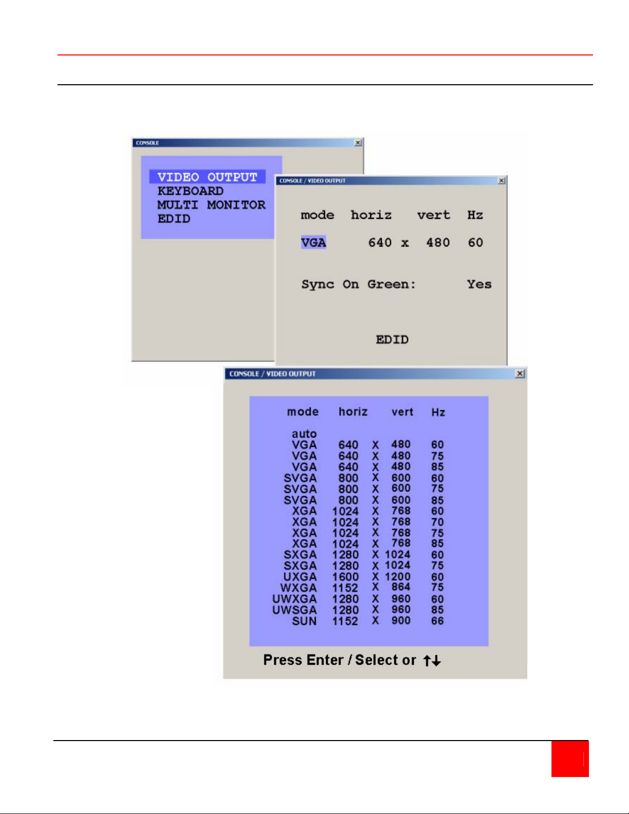
Console
Video output / Keyboard / Multi-Monitor / EDID
Selecting “Console” from the main menu displays the options for the video output, keyboard,
Multi-monitor, and EDID.
Setting the video output
to “auto” the QuadraVista
will read the connected
monitor’s configuration
data and set the mode,
resolution, and frequency
based on the monitors
DDC table. Use the up /
down arrow keys to
select a specific mode,
resolution, and
frequency. The new
setting will display for 10
seconds. Within this
time, press Enter / select
to accept the new video
output setting. No
change is executed if
enter is not pressed
within the 10 second
period.
QUADRAVISTA INSTALLATION AND OPERATIONS MANUAL 25
Page 32
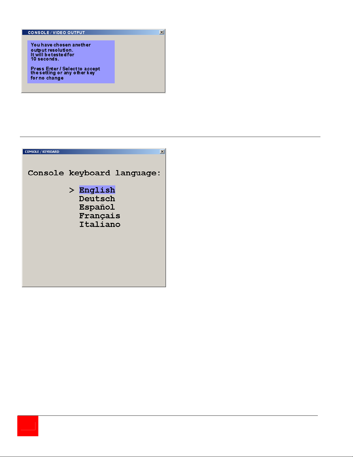
Figure 19. Console, Video output
Console / Keyboard
Changing the video resolution will
display the notification window
shown to the right. Press Enter to
accept the new setting or any other
key for no change.
Figure 20. Keyboard layout
The keyboard option sets the
keyboard language to English,
German, Spanish, French, or
Italian
26 QUADRAVISTA INSTALLATION AND OPERATIONS MANUAL
Page 33
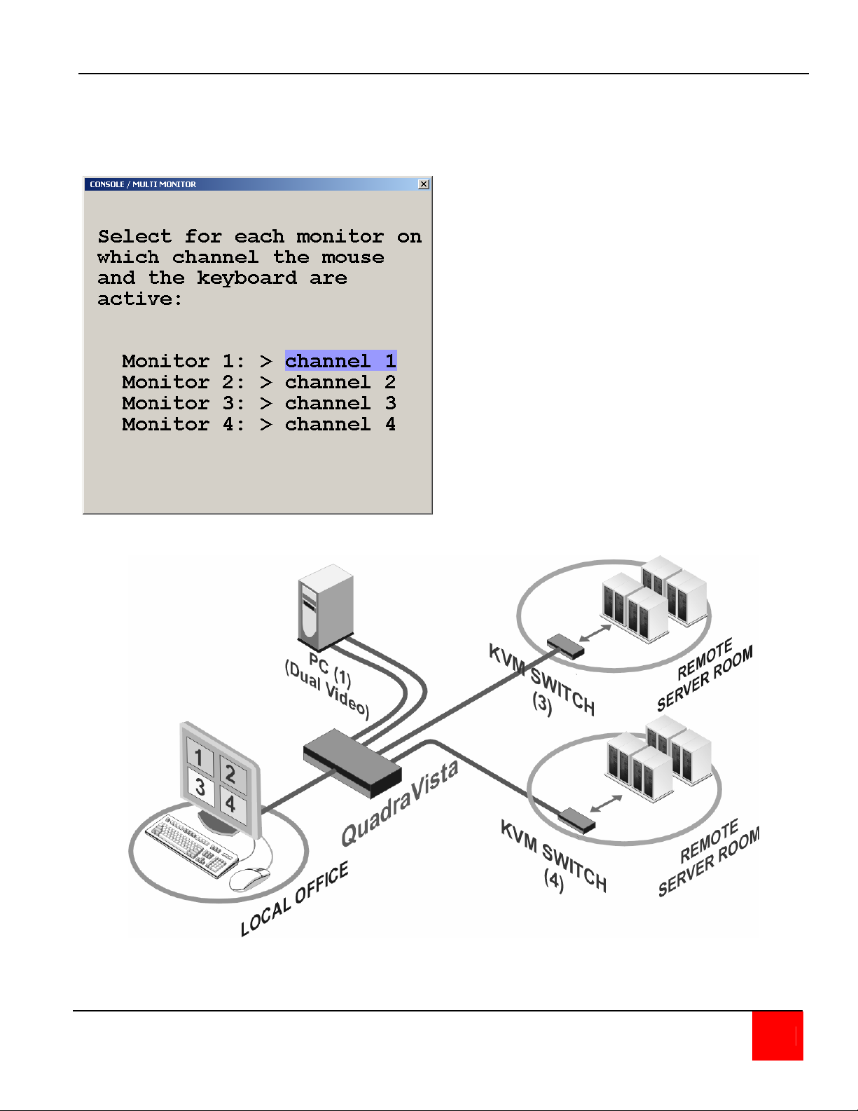
Console / Multi-Monitor
The QuadraVista can be set-up to connect to computers with multiple video outputs. Selecting
Multi monitor opens the Multi monitor window. If your computer uses a graphic card with two
video outputs, assign the computers keyboard and mouse for Monitor 1 and 2 to channel 1.
Example – Multi-Monitor
PC(1) Dual Video keyboard/mouse/video1 to input
#1, video2 to input #2.
KVM Switch (3) to input #3
KVM Switch (4) to input #4
Set Multi-Monitor options to:
Monitor 1: Channel 1
Monitor 2: Channel 1
Monitor 3: Channel 3
Monitor 4: Channel 4
Figure 21. Multi-Monitor setup
QUADRAVISTA INSTALLATION AND OPERATIONS MANUAL 27
Page 34
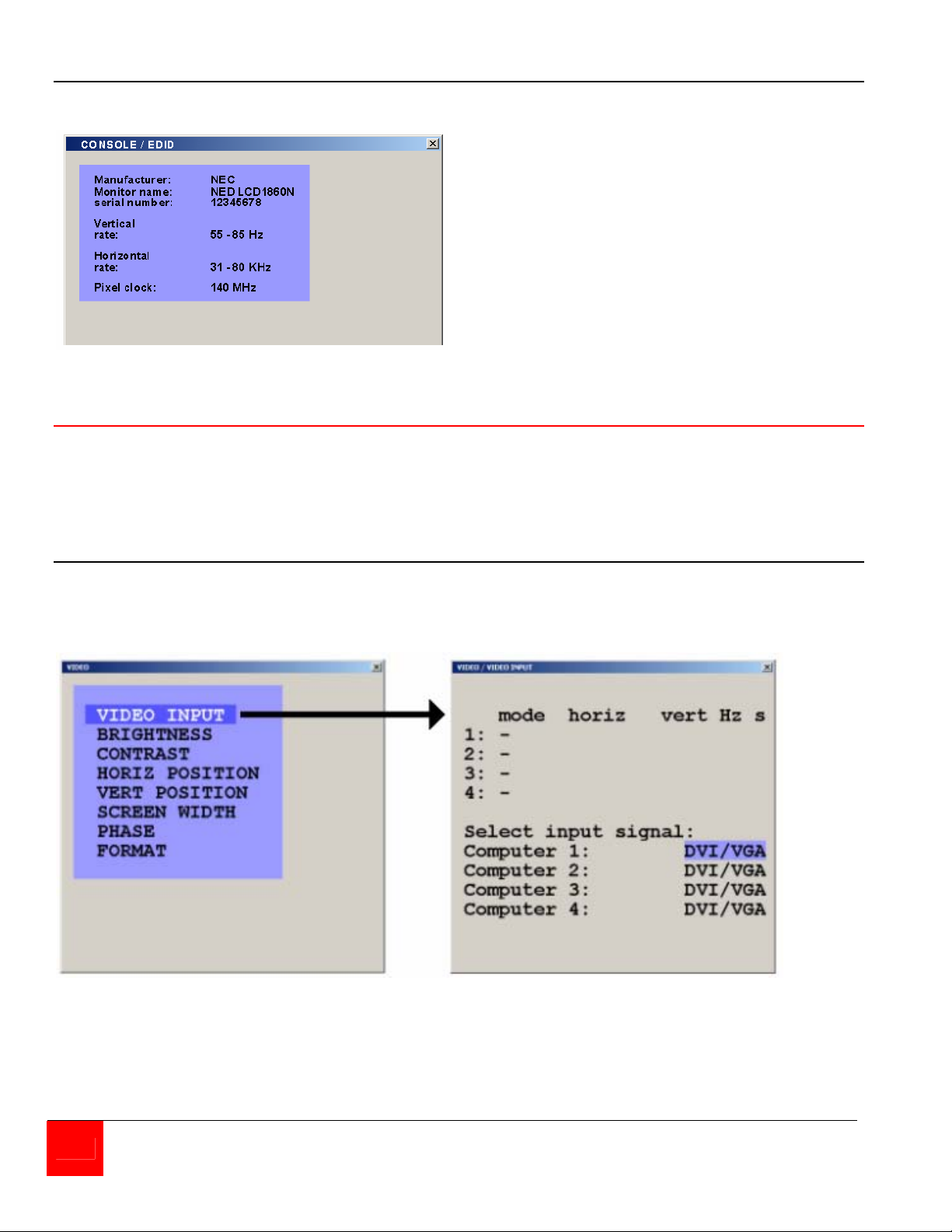
Console / EDID
The EDID menu, when selected, will read
and display the EDID data of your console
monitor. Extended Display Identification
Data is a VESA standard data format that
contains basic information about a monitor
and its capabilities, including vendor
information, maximum image size, color
characteristics, factory pre-set timings,
frequency range limits, and character
strings for the monitor name and serial
number
Figure 22. EDID display
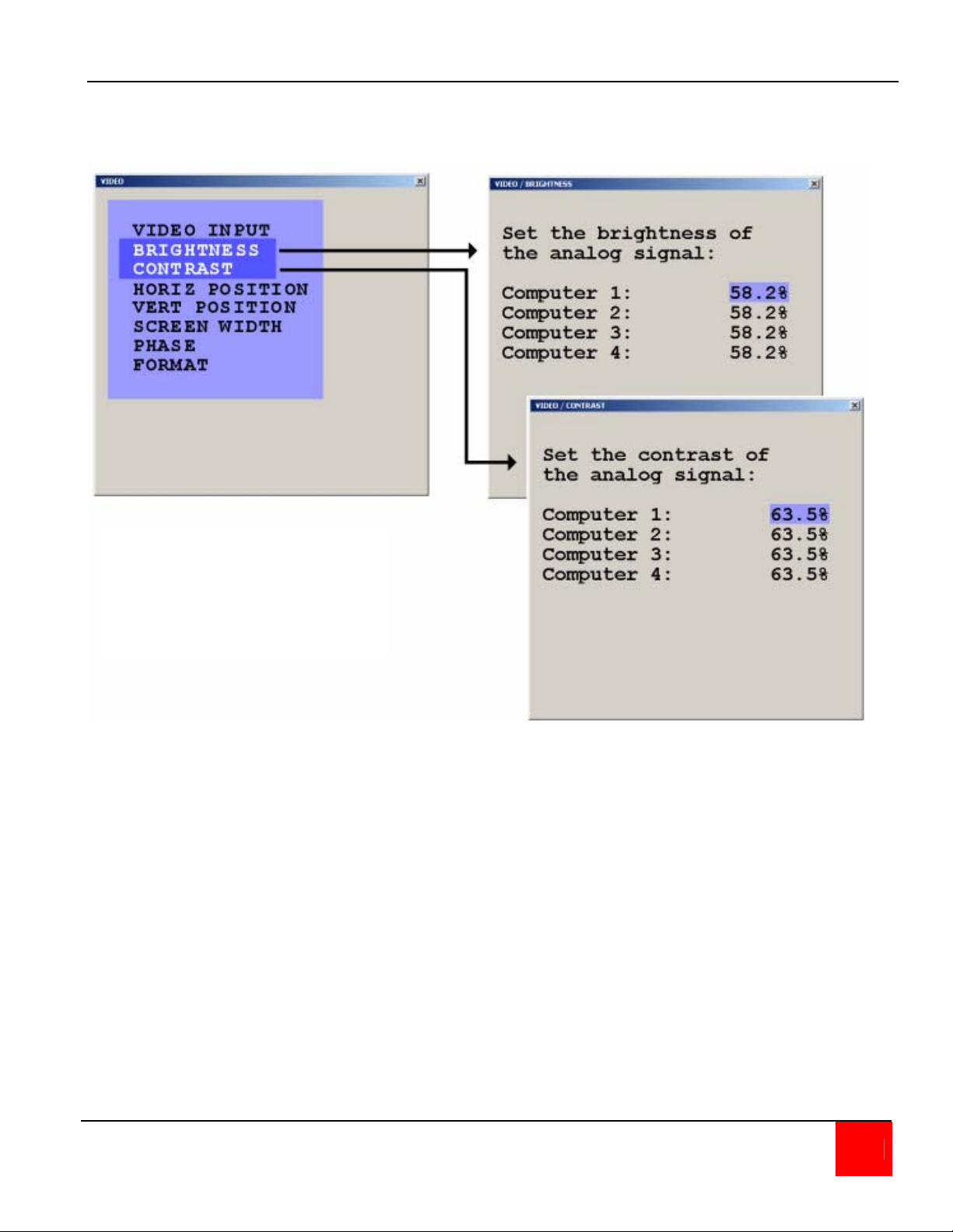
Video
From the main menu, selecting Video will display a menu that allows you to view or change the
connected computers video information, set the brightness, contrast, horizontal position, vertical
position, screen width, phase, and format. Selecting Video Input will display the video information
QuadraVista has automatically detected from the four video inputs (Plug & Play).
Video / Video Input
In the lower part of the Video Input window you define which video input is selected for display. If
both signal inputs DVI/VGA or VGA/DVI are selected, the first one will be processed and
displayed. If there is no signal present the other automatically will be selected and processed
Figure 23, Video input
The "S" column shows the type of video detected,
a = analog, d = digital, g = sync on green,
c = composite sync
Appendix D shows the video formats QuadraVista can support
28 QUADRAVISTA INSTALLATION AND OPERATIONS MANUAL
Page 35
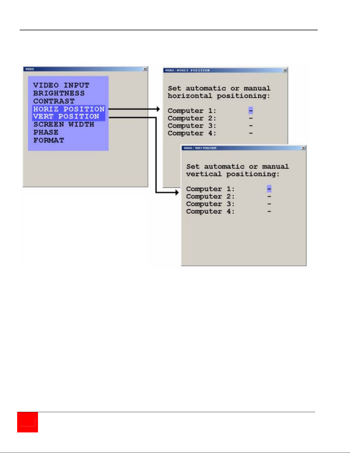
Video / Brightness / Contrast
Using the brightness / contrast menu, you can adjust video brightness and contrast for each
analog video input. Using he arrow keys, select the computer to adjust and increase or decrease
the brightness or contrast.
This setting is used to adjust
brightness or contrast of the
analog input signal for the
desired computer.
Figure 24. Video Brightness / Contrast
QUADRAVISTA INSTALLATION AND OPERATIONS MANUAL 29
Page 36
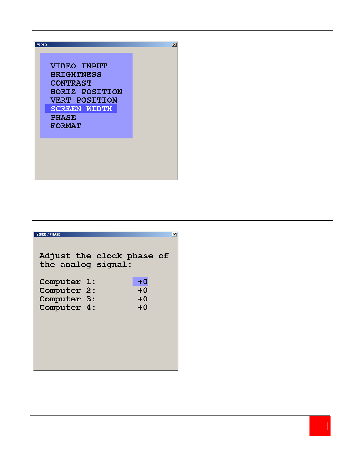
Video / Horizontal and Vertical position
The Horizontal position menu is used to adjust the position of a computer's screen manually
To adjust the horizontal position, select the computer to adjust, and then select the auto/man field.
Select "Man" and adjust the position using the + and – keys. It is recommended that the “Auto”
setting be used for all computers.
The Vertical position menu is used to
adjust the position of a computer's
screen manually
To adjust the vertical position, select
the computer to adjust, and then
select the auto/man field. Select
"man" and adjust the position using
the + and – keys. It is recommended
that the Auto setting be used for all
computers.
Figure 25, Horizontal Position
30 QUADRAVISTA INSTALLATION AND OPERATIONS MANUAL
Page 37
Video / Screen width
The width of the screen can be adjusted
to improve screen quality by selecting
the screen width menu, the computer to
modify, and adjusting the number of
horizontal pixels
Figure 26. Screen width
Video / Phase
If a computer's phasing is incorrect
(blurring screen, incorrect contrast) use
the Phase menu to adjust the video
phasing from the detected value.
Figure 27. Clock phase
QUADRAVISTA INSTALLATION AND OPERATIONS MANUAL 31
Page 38
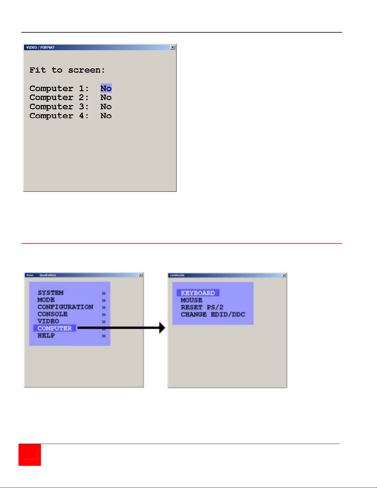
Video / Format
Wide screen monitors (aspect ratio 16:10)
normally display black borders on the left
and right side of the display. Setting “Fit
to screen” to Yes so that computer will
resize the image to fill the entire quadrant
or PiP.
Figure 28. Video format
Computer
Selecting Computer from the main menu will display the features that can be displayed or
modified for each computer connection.
Figure 29. Computer
32 QUADRAVISTA INSTALLATION AND OPERATIONS MANUAL
Page 39
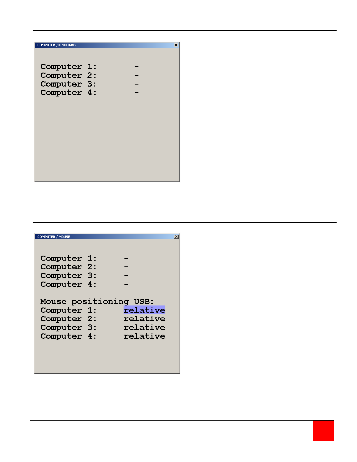
Computer / Keyboard
Selecting keyboard and pressing enter will
display the type of keyboard the system
has detected for each connected
computer (USB, PC1, PC2, or PC3).
Figure 30. Computer / Keyboard
Computer / Mouse
Selecting mouse and pressing enter will
display the type of mouse the system has
detected for each connected computer
(USB, PS/2, or PS/2 wheel)
The Mouse positioning USB: lower section
allows you to choose absolute mouse
positioning when a device is connected to
the console that supports absolute
coordinates such as graphic trays, screen
pads or KVM extenders.
Figure 31. Computer / Mouse
QUADRAVISTA INSTALLATION AND OPERATIONS MANUAL 33
Page 40
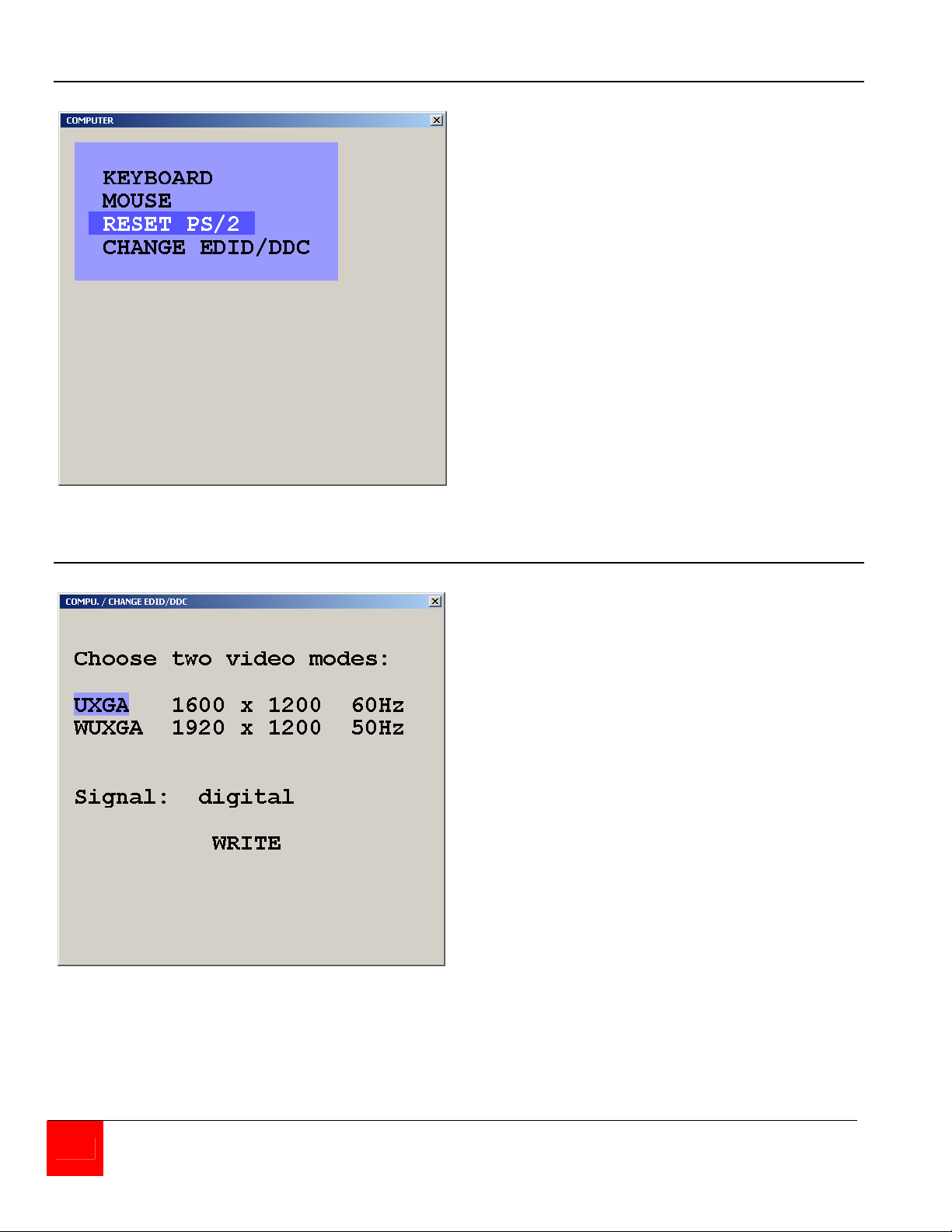
Computer / Reset PS/2
Select Reset PS/2 when the keyboard or
mouse have been disconnected or get out
of sync.
Use the arrow keys or the “+” and “-“ keys
to select the channel to reset and press
enter / select.
Figure 32. Computer / Reset PS/2
Computer / Change EDID/DDC
Figure 33. Computer / Change EDID/DDC
Select Change EDID / DDC to add two
selectable video modes to the list of video
modes available at each of the four video
ports.
Use the left, right arrow keys () to
select the first video mode to add. Once
selected, use the up, down arrow keys
() to select the second video mode to
add. Use the left, right arrow keys ()
to select the second video mode to add.
When both video modes have been
selected, use the up, down arrow keys
() to select signal and the left, right
arrow keys () to select analog or
digital.
With all entries completed, select “WRITE”
and press ENTER / SELECT and the
window shown on the right in Figure 34
will open.
(Procedure continued on next page)
34 QUADRAVISTA INSTALLATION AND OPERATIONS MANUAL
Page 41
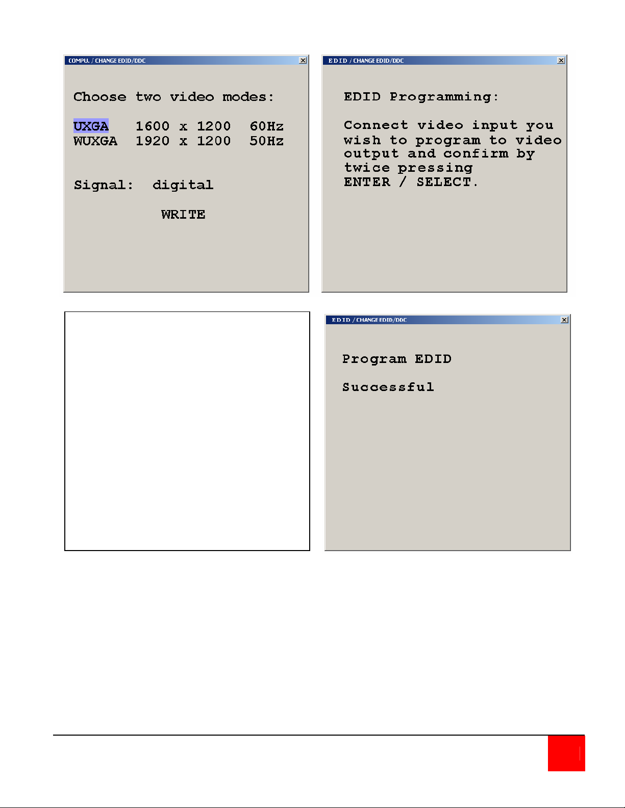
When the window to the above right
displays and before pressing ENTER /
SELECT twice, disconnect the console
monitor cable and the computer monitor
port to program. Connect a DVI male to
male cable from the video output to the
computer video input to program (1-4).
The video will go blank and programming
must be executed blindly. When the DVI
cable has been connected, press ENTER
/ SELECT twice to program the additional
video modes. Reconnect the console
monitor and computer monitor cable and
the display to the right will display.
Repeat this procedure for the other three
video input ports if necessary.
Figure 34. EDID Programming
QUADRAVISTA INSTALLATION AND OPERATIONS MANUAL 35
Page 42
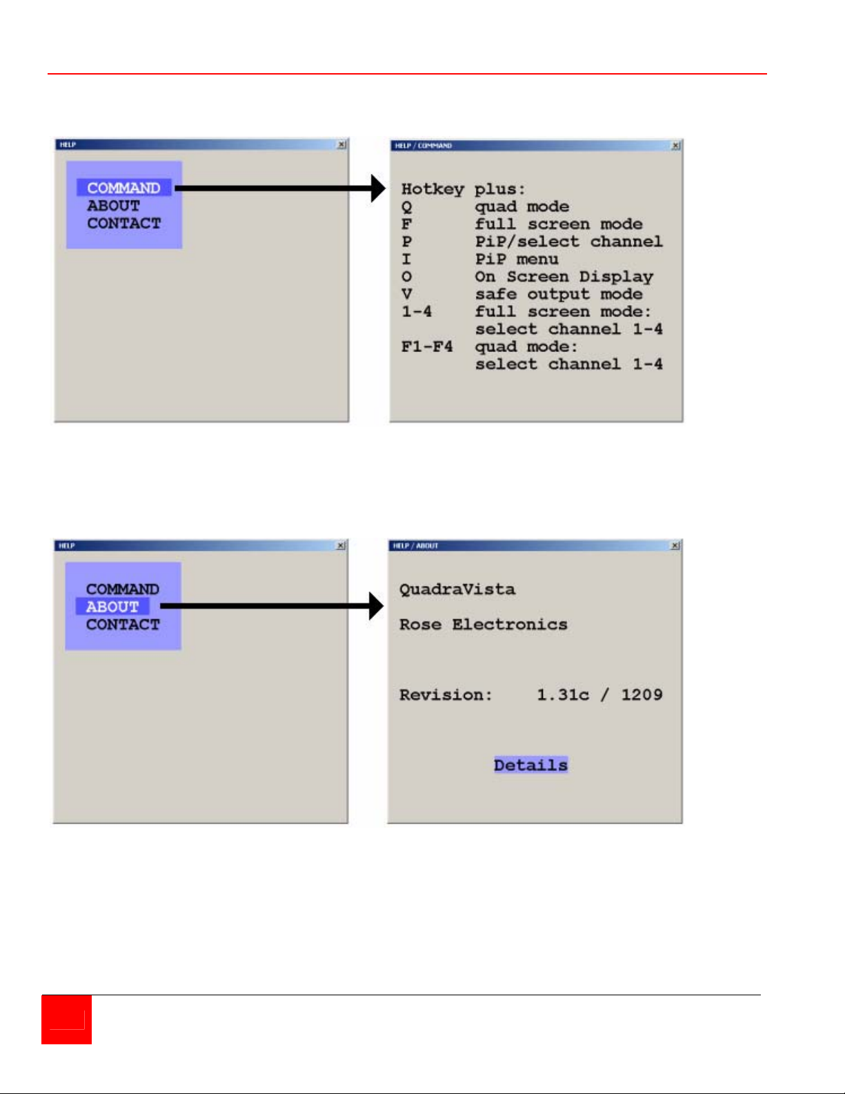
Help
Selecting the help section will display the keyboard command list, about, and contact information.
The Command List option will display the keyboard commands recognized by QuadraVista.
Figure 35. Help / Command
The About section informs you of information pertaining to the QuadraVista.
Figure 36. Help / About
36 QUADRAVISTA INSTALLATION AND OPERATIONS MANUAL
Page 43
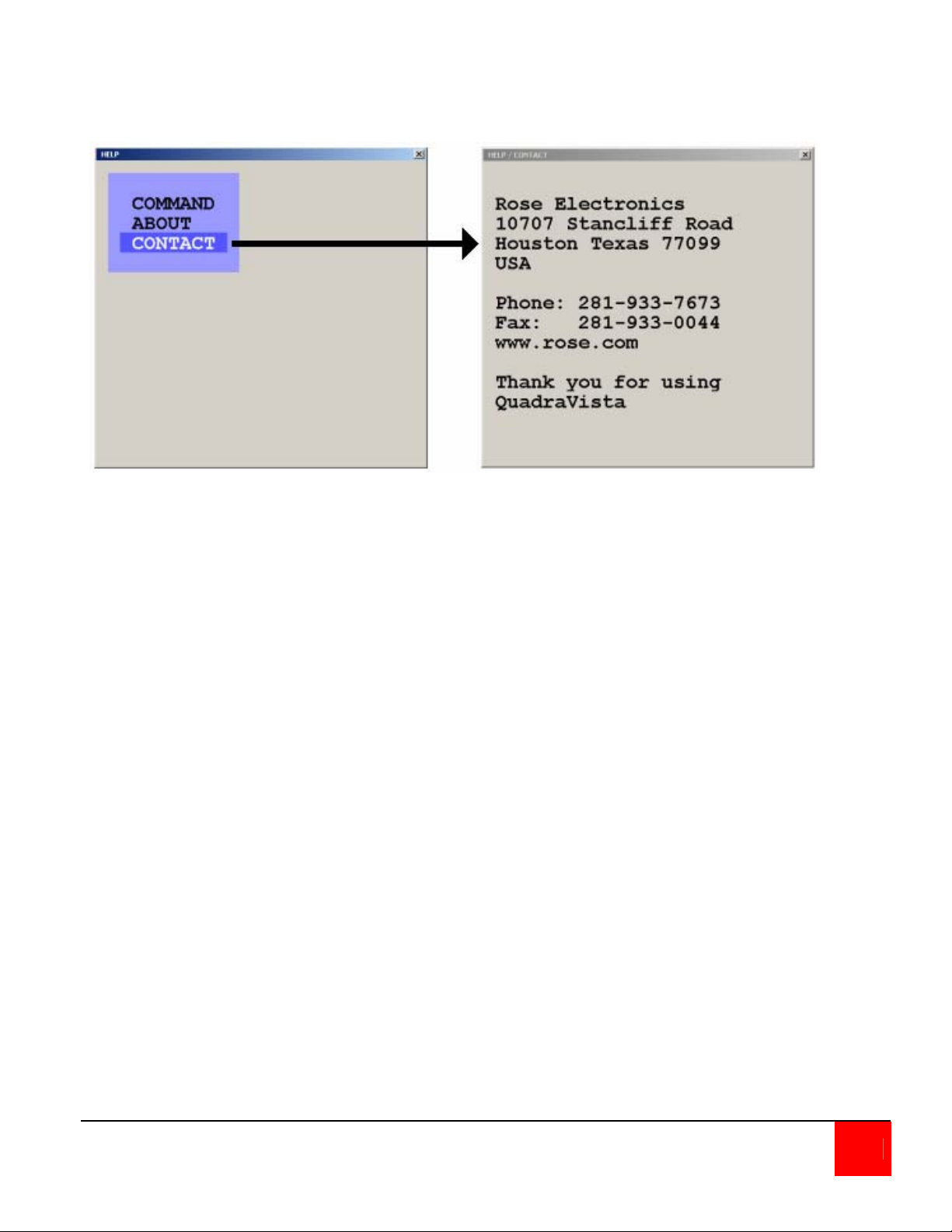
The Contact section provides you with information on who to contact for technical assistance and
other information.
Figure 37. Help / Contact
QUADRAVISTA INSTALLATION AND OPERATIONS MANUAL 37
Page 44
SERIAL OPERATION
Serial Features
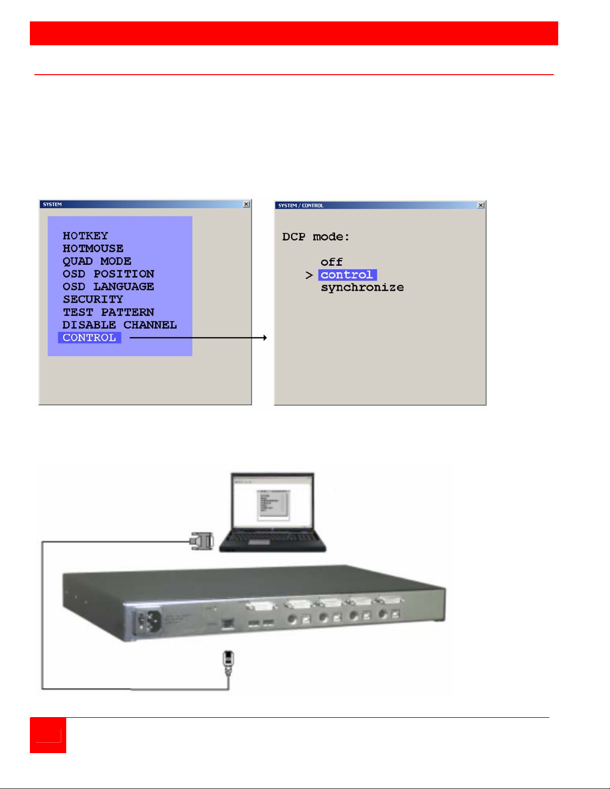
QuadraVista can be configured or controlled from a remote computer by connecting a serial cable
from the computer’s COM port to the QuadraVista’s serial input port.
To remotely configure the QuadraVista (Display / execute the OSD features only), download the
communication software from our web site at /www.rose.com/htm/download.htm in the tech
support section and install it on a remote windows based computer. Next, call up the OSD from
the local console and navigate to the “System, Control” section and change the DCP mode
setting to “control”.
Connect a serial cable from COM1 or COM2 port on the remote Laptop or PC to the RS232 port
on the rear panel of QuadraVista as shown below
Remote
Laptop or PC
Serial
Cable
DB9F to RJ45M
P/N CAB-QVRJ006
RS 232
Port
Figure 38, Serial connections
38 QUADRAVISTA INSTALLATION AND OPERATIONS MANUAL
Page 45
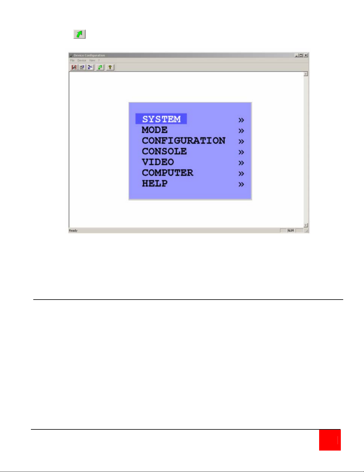
Execute the Serial Communication software and the window shown below will display.
Click on the ICON to connect and display the OSD on the remote computer
Remotely navigate within the OSD menu system from the remote computer the same way as you
would using the local console. All OSD menus can be accessed using the arrow keys and the
Enter / Select key.
DCP Synchronizing Multiple Units
In systems that use multiple QuadraVista’s, the display mode can be synchronized so all units are
the same display mode. To accomplish this, first display the OSD and navigate to the “Control”
section (System, Control). Use the up/down arrow keys to select “Synchronization”, then exit the
OSD.
Each time you restart a V-Switch quad set to synchronization, it will send all its settings to the
next connected device. This process also takes place after activating Synchronization in the
OSD menu.
QUADRAVISTA INSTALLATION AND OPERATIONS MANUAL 39
Page 46
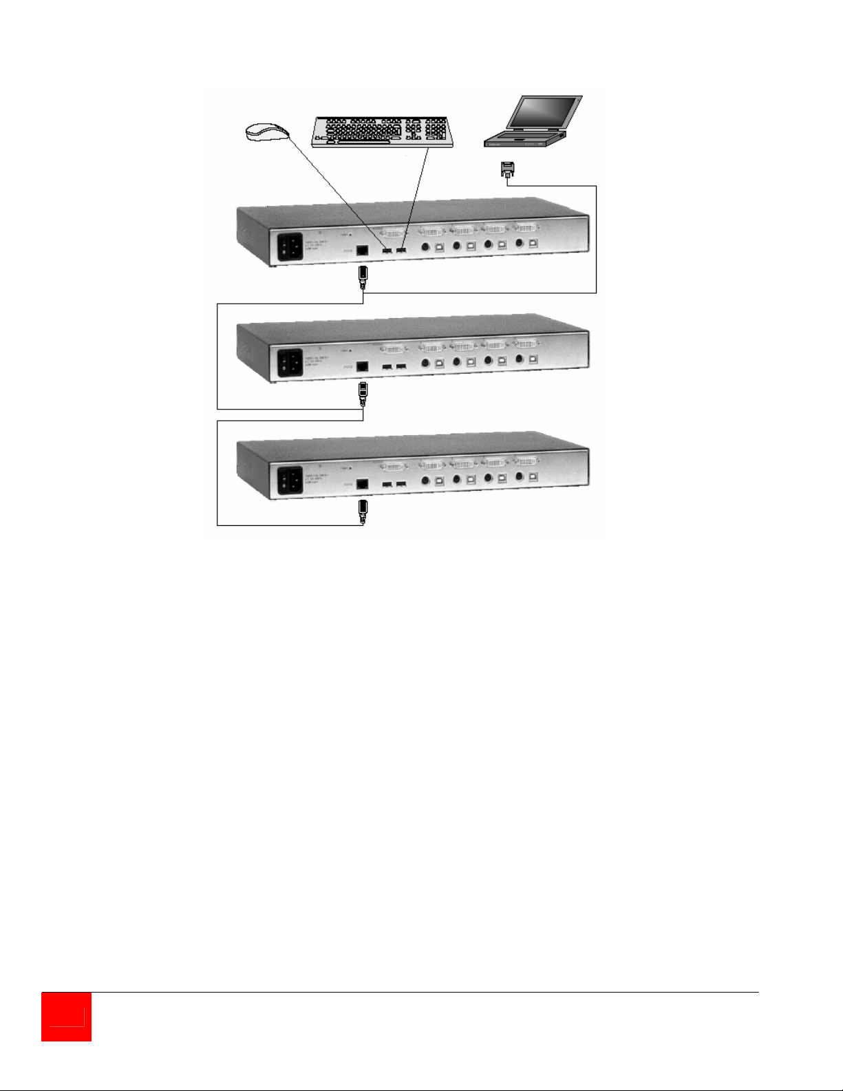
Connect the multiple unit system as shown below using a special “Y” serial cable.
When starting a chain of devices, always start by first switching on the device at the end of the
chain. When the device has completed its startup phase and sent its DCP messages, switch on
the next device in the chain. Finally, switch on the first device in the chain, which synchronizes
the settings of all other devices in the chain with its own settings as it starts up. The synchronized
chain can have any length.
Do not connect the last unit to the first to create a loop.
40 QUADRAVISTA INSTALLATION AND OPERATIONS MANUAL
Page 47

DCP/XML Feature
The QuadraVista can be controlled remotely from a PC or laptop connected to the RS232 port
(serial) using the DCP/XML feature. This feature is different from the OSD serial features. The
serial feature allows only the OSD functions to be performed. The DCP/XML feature sends a
DCP/XML message containing the defined elements like switching to a given port, changing the
display mode, defining the PiP features, and other items.
To use the DCP/XML feature, connect the system in the serial configuration as shown in
Figure 38. The PC or laptop must have a serial communication program installed like
HyperTerminal. Configure the communication program for the following:
• Transfer rate – 57600 Baud
• Data Bits – 8
• No parity
• Stop Bit – 1
• No flow control
Connect to QuadraVista and send the DCP/XML text message containing the controlling script. A
simple example of sending a DCP/XML text message that will switch ports is shown below.
Tabbed spacing in the below example is for readability only; the actual text file does not need the
spacing.
<dcp-xml>
<device>
<mode>
<console>
<channel>0</channel>
</console>
<video>
<channel>0</channel>
</video>
</mode>
</device>
</dcp-xml>
This example switches the console and video to channel 0
Note: DCP/XML channel 0 = QuadraVista channel 1
DCP/XML channel 1 = QuadraVista channel 2
DCP/XML channel 2 = QuadraVista channel 3
DCP/XML channel 3 = QuadraVista channel 4
QUADRAVISTA INSTALLATION AND OPERATIONS MANUAL 41
Page 48

An example of a DCP/XML message containing all defined elements is shown below:
<dcp-xml>
<device>
<type>VSQ</type>
<version>
<dcp-protocol>1.0</dcp-protocol>
<hardware>32</hardware>
<software>1.30</software>
</version>
<mode>
<console>
<channel>0</channel>
</console>
<video>
<channel>0</cjannel>
<layout>full</layout>
<pip>
<layout>triple-gap</layout>
<size>15</size>
<offset>5</offset>
<direct>
<channel>0</channel>
</direct>
<fixed>
<channel>0</channel>
</fixed>
<scan-time>1</scan-time>
</pip>
</video>
</mode>
</decide>
</dcp-xml>
42 QUADRAVISTA INSTALLATION AND OPERATIONS MANUAL
Page 49

DCP/XML System Querying
Using the DCP/XML feature, the QuadraVista can be queried to request setting information.
Queries are only replied to in the DCP control mode. Sending the below text script to
QuadraVista using Hyper Terminal, queries for the entire device status:
<dcp-xml/>
Queries can be combined with changes in one text script. The following is an example of
querying for the console information and setting the video to channel 1.
<dcp-xml>
<device>
<mode>
<console/>
<video>
<channel>0</channel>
</video>
</mode>
</device>
</dcp-xml>
The console and video are queried in the below script.
<dcp-xml>
<device>
<mode>
<console/>
<video>
<channel/>
</video>
</mode>
</device>
</dcp-xml>
The response to the above query is:
<dcp-xml>
<device>
<mode>
<console>
<channel>0</channel>
</console>
<video>
<channel>0</channel>
</video>
</mode>
</device>
</dcp-xml>
The above response shows that the console and video are connected to channel 1.
QUADRAVISTA INSTALLATION AND OPERATIONS MANUAL 43
Page 50

DCP error messages:
malformed xml Malformed XML.
tag mismatch Opening and closing tags do not match.
tag not closed Opening tag without matching closing tag. Only occurs with
Simple Elements. In the case of Complex Elements, a
timeout error is reported.
subtag in simple element A simple element contains a subtag.
tag name too long Tag name exceeding 16 characters.
wrong data type Incorrect data type. For list types, such as Device Name,
this error message also refers to values not included in the
list.
content too long Contents of a Simple Element exceeding 30 characters.
timeout Receive timeout. This error message is displayed if a DCP
message is not complete after expiry of the timeout, but no
other error has occurred.
parser stack overflow This error occurs when unknown elements are nested too
deeply, or in the case of an internal error.
internal parser error Internal error parser error.
unknown error Unknown error.
DCP Communication
DCP/XML messages exceeding 38 characters must be divided into individual lines before being
sent to a device.
Replies sent by a device are also divided into lines.
When sending a DCP message, the following constraints apply:
Linefeed: LF
Linefeed (0x0A) is used as terminating character of each line.
44 QUADRAVISTA INSTALLATION AND OPERATIONS MANUAL
Page 51

Whitespace: TAB, SPACE, CR
Whitespace characters are TAB (0x09), Space (0x20) and Carriage Return (0x0D).
Whitespace may occur anywhere between two tags, except at the start of a line and inside
simple elements
Whitespace is ignored.
Line length: maximum 38 characters
The line length may not exceed 38 characters.
(Not including the terminating LF.)
Timeout: 750 ms
Timeout for DCP messages is 750 milliseconds.
DCP messages containing errors are not regarded as completed until the timeout period
has elapsed.
Therefore, it is recommended to wait for this time between DCP messages to allow the
parser to handle possible errors.
Correct messages are processed immediately upon completion.
Unknown elements
Unknown tags in a DCP message are ignored for the sake of upwards compatibility of the
protocol.
Messages containing unknown elements must still be syntactically correct.
Unknown tags may not be nested deeper than 5 levels.
Empty elements
An empty element is an opening tag immediately followed by a closing tag.
((tag)) may be abbreviated as ((tag))
QUADRAVISTA INSTALLATION AND OPERATIONS MANUAL 45
Page 52
SERVICE and MAINTENANCE
Service Information
Maintenance and Repair
This Unit does not contain any internal user-serviceable parts. In the event a Unit needs repair or
maintenance, you must first obtain a Return Authorization (RA) number from Rose Electronics or
an authorized repair center. This Return Authorization number must appear on the outside of the
shipping container.
See Limited Warranty for more information.
When returning a Unit, it should be double-packed in the original container or equivalent, insured
and shipped to:
Rose Electronics
Attn: RA__________
10707 Stancliff Road
Houston, Texas 77099 USA
Technical Support
If you are experiencing problems, or need assistance in setting up, configuring or operating your
QuadraVista, consult the appropriate sections of this manual. If, however, you require additional
information or assistance, please contact the Rose Electronics Technical Support Department at:
Technical Support hours are from: 8:00 am to 6:00 pm CST (USA), Monday through Friday.
Please report any malfunctions in the operation of this Unit or any discrepancies in this manual to
the Rose Electronics Technical Support Department.
46 QUADRAVISTA INSTALLATION AND OPERATIONS MANUAL
Page 53

SAFETY
Safety
The QuadraVista has been tested for conformance to safety regulations and requirements, and
has been certified for international use. Like all electronic equipment, the QuadraVista should be
used with care. To protect yourself from possible injury and to minimize the risk of damage to the
Unit, read and follow these safety instructions.
Follow all instructions and warnings marked on this Unit.
Except where explained in this manual, do not attempt to service this Unit yourself.
Do not use this Unit near water.
Assure that the placement of this Unit is on a stable surface.
Provide proper ventilation and air circulation.
Keep connection cables clear of obstructions that might cause damage to them.
Use only power cords, power adapter and connection cables designed for this Unit.
Keep objects that might damage this Unit and liquids that may spill, clear from this Unit. Liquids
and foreign objects might come in contact with voltage points that could create a risk of fire or
electrical shock.
Do not use liquid or aerosol cleaners to clean this Unit. Always unplug this Unit from its electrical
outlet before cleaning.
Unplug this Unit refer servicing to a qualified service center if any of the following conditions
occur:
y The connection cables are damaged or frayed.
y The Unit has been exposed to any liquids.
y The Unit does not operate normally when all operating instructions have been followed.
y The Unit has been dropped or the case has been damaged.
y The Unit exhibits a distinct change in performance, indicating a need for service.
QUADRAVISTA INSTALLATION AND OPERATIONS MANUAL 47
Page 54
Safety and EMC Regulatory Statements
Safety information
Documentation reference symbol. If the product is marked with this symbol, refer to the
product documentation to get more information about the product.
WARNING A WARNING in the manual denotes a hazard that can cause injury or death.
CAUTION A CAUTION in the manual denotes a hazard that can damage equipment.
Do not proceed beyond a WARNING or CAUTION notice until you have understood the
hazardous conditions and have taken appropriate steps.
Grounding
These are Safety Class I products and have protective earthing terminals. There must be an uninterruptible safety earth ground from the main power source to the product’s input wiring
terminals, power cord, or supplied power cord set. Whenever it is likely that the protection has
been impaired, disconnect the power cord until the ground has been restored.
Servicing
There are no user-serviceable parts inside these products. Only service-trained personnel must
perform any servicing, maintenance, or repair.
The user may adjust only items mentioned in this manual.
48 QUADRAVISTA INSTALLATION AND OPERATIONS MANUAL
Page 55
Appendix A. Specifications
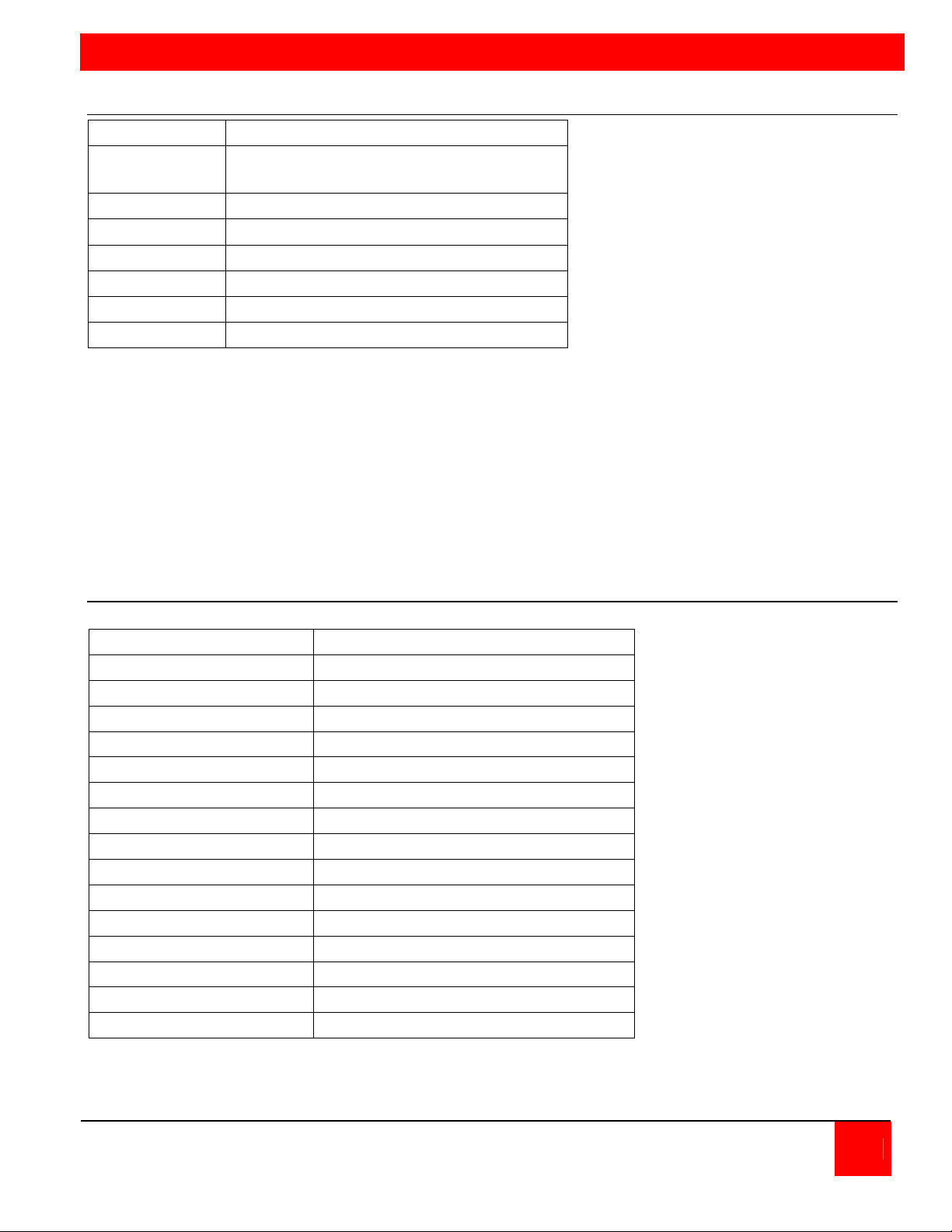
Resolution 1900 x 1200
Video
compatibility
Keyboard USB / PS/2 (Computers), USB (KVM)
Mouse USB / PS/2 (Computers), USB (KVM)
Dimensions W- 17.125" / D – 9.125" / H – 1.75"
Weight 6.3 lbs
Approval Europe: CE
VGA to UXGA / DVI
APPENDICES
Appendix B. Parts and cables
Part Number Description
QV-4KVMDVI QuadraVista unit
CAB-DVIIMMnnn DVI-I to DVI-I (male/male)
CAB-DVIIMFnnn DVI-I to DVI-I (male/female)
CAB-DVIIMVMnnn VGA to DVI-I (male/male)
CAB-DVIIMVFnnn DVI-I to VGA (male/female)
CAB-DVIDMMnnn DVI-D to DVI-D (male/male)
CAB-USBABnnn USB-A to USB-B (male/male)
CAB-CXUSBCnnn DB25 to VGA/USB
CAB-CXV66MMnnn VGA/PS2 to VGA/PS2 (male/male)
CAB-C1VS0600Cnnn DB25 to VGA-PS/2
CAB-MD6MMnnn PS/2 to PS/2 (male/male)
CAB-MD6M2MD6M PS/2 “Y” cable
CAB-QVRJ006 Serial DB9 to RJ45 cable
ACC-DVIMVF DVI-I to VGA adapter
RM-QV19 Rack Mount kit
QUADRAVISTA INSTALLATION AND OPERATIONS MANUAL 49
Page 56

Appendix C. Factory Defaults
The Below table shows the factory default settings. When “Factory Reset” is executed, the unit
configuration is changed from the user settings to the below default settings.
Section Function Default Setting
SYSTEM
MODE
CONFIGURE
CONSOLE
Hotkey
Hotmouse
Quad Mode
OSD Position
OSD Language
Security
Test Pattern
Disable Channel
Control
Pip
Start
Backup
Recall
Factory Reset
Video Output
Keyboard
Multi-Monitor
EDID
Ctrl + Alt
On / 5 Sec.
Timeout = 5 Sec.
Centered
English
None (Level 0)
None
None
Off
Size = 15%; Zoom = 1; Mode = triple; gap,
Offset = 0%
Quad / active channel = 1
User initiated
User initiated
User initiated
Auto
English
Monitor 1, 2, 3, 4 = channel 1, 2, 3, 4
Display information only
VIDEO
COMPUTER
HELP
Video Input
Brightness
Contrast
Horiz. Position
Vert. Position
Screen width
Phase
Format
Keyboard
Mouse
Reset PS/2
Change EDID / DDC
Command
About
Contact
DVI / VGA (all channels)
58.2% (all analog channels)
63.5% (all analog channels)
auto (all channels)
auto (all channels)
+0 (all channels)
+0 (all channels)
No (all channels)
N/A
N/A
N/A
No
N/A (Lists available keyboard commands)
N/A (Displays unit information, version)
N/A (Displays contact information)
50 QUADRAVISTA INSTALLATION AND OPERATIONS MANUAL
Page 57

Appendix D. Supported Video-In Formats
Mode Resolution Rate
Analog
CGA 640 x 350 85 85 HDTVp 1280 x 720 - 60
CGA 640 x 400 85 85 WXGA 1280 X 768 60 60
EGA 720 x 400 70 70 WXGAp 1366 X 768 - 22-60
EGA 720 x 400 85 85 UWXGA 1280 x 960 60 60
VGA 640 x 480 60 22-60 UWXGA 1280 x 960 85 85
VGA 640 x 480 72 72 SXGA 1280 x 1024 50 50
VGA 640 x 480 75 75 SXGA 1280 x 1024 60 60
VGA 640 x 480 85 85 SXGA 1280 x 1024 72 72
SVGA 800 x 600 56 22-56 SXGA 1280 x 1024 75 75
SVGA 800 x 600 60 60 SXGA 1280 x 1024 85 85
SVGA 800 x 600 72 72 SXGA 1400 x 1050
SVGA 800 x 600 75 75 SGI 1600 x 1024 60 60
SVGA 800 x 600 85 85-180 UXGA 1600 x 1200 50 50
XGA 1024 x 768 60 22-60 UXGA 1600 x 1200 60 60
XGA 1024 x 768 70 70 UXGAr 1600 x 1200 50 50
XGA 1024 x 768 75 75 UXGAr 1600 x 1200 60 60
XGA 1024 x 768 85 85 WSXGA 1680 x 1050
WXGA 1152 x 864 75 75 HDTVp 1920 X 1080 - 22-24
SUN 1152 x 900 66 66 HDTVp 1920 X 1080 - 50
HDTVp 1280 x 720 - 22-50 HDTVp 1920 X 1080 - 60
HDTVp 1280 x 720 - 60 WUXGA 1920 X 1200 - 22-50
HDTVp 1280 x 720 - 22-50 WUXGA 1920 X 1200 - 60
Rate
Digital
Mode Resolution Rate
Analog
Rate
Digital
QUADRAVISTA INSTALLATION AND OPERATIONS MANUAL 51
Page 58

NOTES
52 QUADRAVISTA INSTALLATION AND OPERATIONS MANUAL
Page 59

Page 60

10707 Stancliff Road Phone (281) 933-7673
Houston, Texas 77099 www.rose.com
 Loading...