

Roper Microwave Hood Combination, 4B75546A, 4358154 Installation Instructions Manual
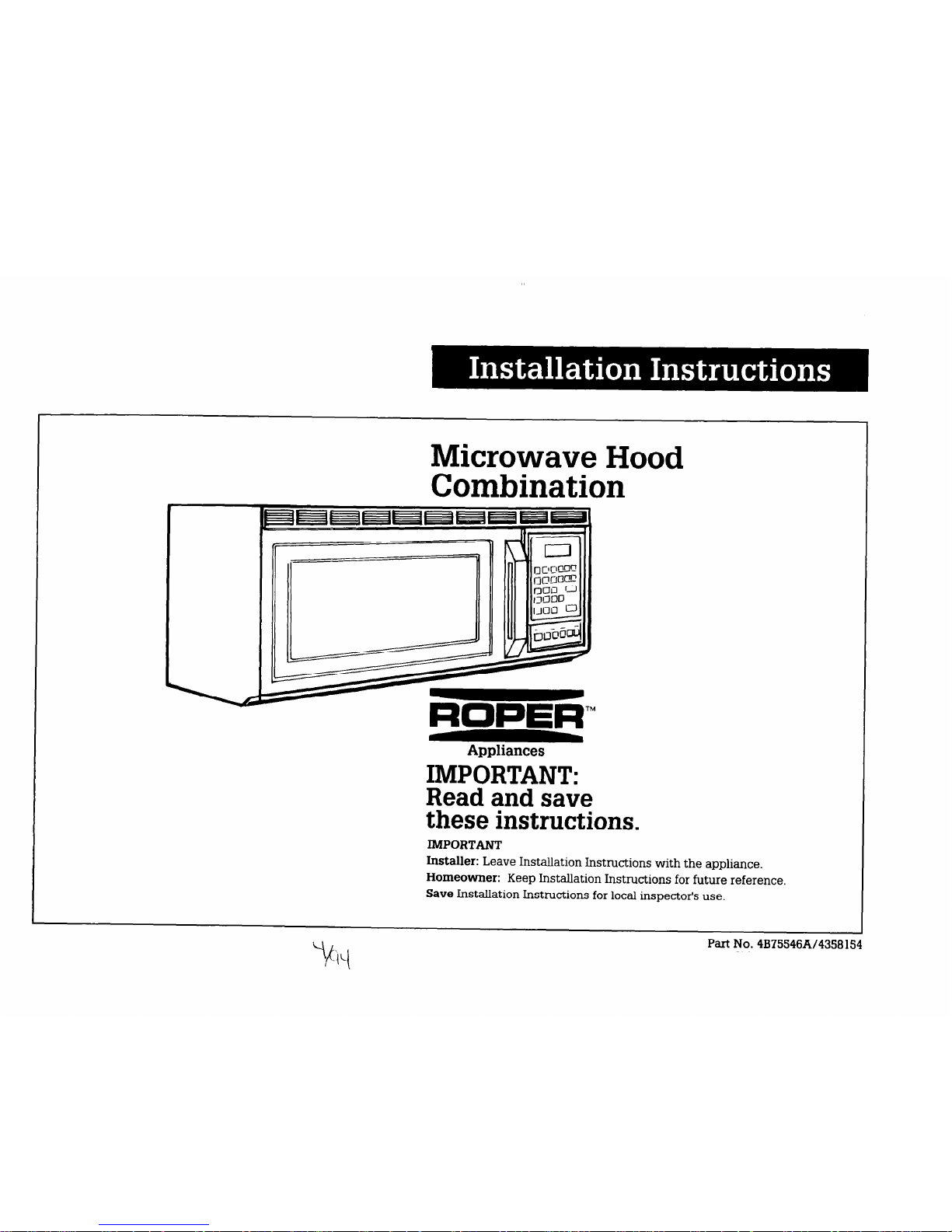
Microwave Hood
Combination
Appliances
IMPORTANT:
Read and save
these instructions.
IMPORTANT
Installer: Leave Installation Instructions with the appliance.
Homeowner: Keep Installation Instructions for future reference.
Save Installation Instructions for local inspector’s use.
Part No. 4B75546A14358 154
Beforeyoustart...
Remove all contents from the upper
cabinet.
Important: Observe all governing
codes and ordinances.
Check location where microwave oven
will be installed. The wall must be
strong enough to support the microwave
oven weight of 150 lbs., plus the weight
of any items placed inside the
microwave or the upper cabinet. The
location should be away from strong
draft areas, such as windows, doors,
and strong heating vents. The
microwave oven should be located for
convenient use in the kitchen.
Proper installation is the installer’s
responsibility. A qualified technician
should install this microwave oven.
Make sure you have everything
necessary for correct installation.
It is the responsibility of the installer to
comply with the installation clearances
specified on the serial/rating plate.
The serial/rating plate is located
Excessive Microwave Energy
Exposure
. Do Not attempt to operate this
microwave oven with the door
open.
. Do Not tamper with or defeat
the safety interlocks.
. Do Not place objects between
the microwave oven front face
and the door.
. Do Not allow soil or cleaner
residue to accumulate on
sealing surface of microwave
oven door.
. Do Not operate microwave
oven if it is damaged.
. The microwave oven door
must close properly to provide
safe operation. Do Not use
microwave oven if door is bent;
hinges and latches are broken
or loose; or door seals, sealing
surfaces or glass are broken.
n
The microwave oven should
only be adjusted and repaired
by a qualified repair person.
. Have a qualified repair person
check for microwave leakage
if a repair is made.
Failure to use microwave oven
except as instructed may result
in exposure to excessive
microwave energy.
behind the micr&vave oven door on
the front frame of the microwave oven.
Electrical ground is required. See
Electrical requirements.
II I
For comer installations, allow
enough clearance to fully open
door so that rack and cooking
utensils can be removed
Y
I-
30” min cabinet
opening width
c
I Y
t
15” minimum’microwave
oven to cooking surface
or countertop
30” min~clearance from
. . .
Wall construction should
be a minimum of 2” x 4”
wood studding and 3/8”
thickness drywall or
Use templates included
with installation
instructions.
Remove all packaging material from
inside microwave oven. Check the
microwave oven for damage - see
WARNING for excessive microwave
energy exposure. If any damage is
evident, do Not operate the microwave
oven until it is checked by an authorized
Whirlpool service technician
Personal Injury Hazard
Two people are required to lift
this microwave oven.
Failure to use more than one
person during installation may
result in personal injury.
. This microwave oven must be
mounted against and supported
by a flat, vertical wall.
. This microwave oven must be
attached with two lag screws
to a minimum of one, vertical
2” x 4” wall stud.
H Do Not mount microwave oven
to an island or peninsula cabinet.
w The microwave oven top and
rear supporting structures must
be capable of supporting 150 lbs.,
plus the weight of any items
placed inside the microwave
oven or upper cabinet.
Failure to mount the microwave
oven as instructed could result in
personal injury and/or property
damage.
Electrical Shock Hazard
It is the customer’s responsibility:
. To contact a qualified
electrical installer.
. To assure that the electrical
installation is adequate and in
conformance with National
Electrical Code, ANSVNFPA 70latest edition*, and all local codes
and ordinances.
Failure to do so could result in fire,
electrical shock or other personal
injury.
Tools and
materials needed
Property Damage
Place a portion of carton or another
heavy material over the countertop
or cooktop before installing the
microwave oven. Do Not use a
plastic cover.
Failure to protect cooking surface
or countertop could result in
property damage.
I
NOTE:
Do Not use this microwave oven
for commercial purposes. This
microwave oven is designed for
household use only.
316” and 314”
wood drill bits
Parts supplied
for installation:
saber saw V 6-j
,.
//A
m
4, l/4” x 3”
toggle bolts
69
4 spring
toggle-heads
2, l/4” x 2” bolts
m Take special care when drilling
holes into the wall. Electrical
wires may be concealed behind
the wall covering and contact
with them could result in
electrical shock.
m Locate any electrical circuits
that could be affected by the
installation of this product and
disconnect power circuit.
Failure to do so could result in
electrical shock.
screwdriver II -
gq
4,114” x 2” lag screws
&
1, power cord clamp and
1, mounting screw
2 tapping screws
(dark-colored)
(bright-colored)
measuring rape
carton or another heavy material
1 power cord
bushing
l
Copies of the standard listed
may be obtained from:
National Fire Protection Association
Batterymarch Park
Quincy, Massachusetts 02269
for covering countertop
Special hardware and tools are required
for brick or masonry walls. At least four
anchor bolts must be anchored into the
wall and the mounting area must be
capable of meeting the 150 lb.-weight
requirement.
2 filter screens
Panel A

Electrical
Venting
requirements
requirements
Electrical ground is required on
this appliance.
Electrical Shock Hazard
w Electrical ground is required on
this appliance.
n
Improper connection of
the equipment-grounding
conductor can result in
electrical shock.
n
Check with a qualified elect&
cian if you are in doubt as to
whether the appliance is
properly grounded.
n
Do Not use au extension cord
with this appliance.
Such use may result in a fire,
electrical shock or other personal
iujury.
n
Do Not have a fuse in the
neutral or grounding circuit. A
fuse in the neutral or grounding
circuit could result in electrical
shock.
Failure to follow these instructions could result in electricaI
shock or other personal injury.
Instructions for local electrical
A 120-volt, 60-Hz, AC only, 15- or
20-ampere, fused electrical supply
(located in the upper cabinet as close as
possible to the microwave oven) is
required. Time-delay fuse or circuit
breaker is recommended. It
is recommended that a separate circuit
serving only this appliance
be orovided.
Recommended
grounding method
Do Not, under any circumstances,
remove the power supply cord
grounding prong.
For your personal safety, this appliance
must be grounded. This appliance is
equipped with a power supply cord
having a 3-prong grounding plug. To
minimize possible shock hazard, the
cord must be plugged into a mating
3-prong grounding-type wall receptacle,
grounded in accordance with the
National Electrical Code, ANWNFPA
70-latest edition* and all local codes
and ordinances. See Figure 1. If a
mating wall receptacle is not available,
it is the personal responsibility and
obligation of the customer to have
a properly grounded, 3-prong wall
receptacle installed by a qualified
electrician.
3-prong
grounding plug
power supply cord
Panel B
3-prong grounding
type wall receptacle
Figure 1
Ductwork needed for installation is
not included. Wall and roof caps used
must have back-draft damper.
Fire Hazard
. Venting system must terminate
to the outside.
n
Do Not terminate the ductwork
in an attic or other enclosed
space.
. Do Not use 4” laundry-type
wall caps.
n
Do Not use plastic or flexible
plastic ductwork.
Failure to follow recommended
venting procedures may result
in a fire.
Rigid metal ductwork is
recommended. Flexible ductwork is
Not recommended. If flexible metal
ductwork is used, calculate each foot of
flexible ductwork as two feet of straight
metal ductwork. Flexible elbows count
twice as much as standard elbows.
Determine which venting method
(roof-venting, wall-venting or ventless)
you need to use. This microwave oven
is equipped for roof- or wall-venting
installation. Some models cannot be
installed using the ventless
(recirculating) method.
The length of the ductwork and number
of elbows should be kept to a minimum
to provide efficient performance. The
size of ductwork should be uniform. Do
Not install two elbows together. Use
duct tape to seal all joints in the duct
system. Use caulking to seal exterior
wall or roof opening around cap.
Figures 2-5 show common venting
methods and types of materials needed.
Note: If the rear exhaust method is
chosen, be sure that there is proper
clearance within the wall for the
ductwork.
Roof venting
-- .
Wall venting
Figure 2
roof cap
-
w
3-l/4” x lo”
duct
-l-ll
through-the-roof
Figure 3
a wallcap
3-l/4’ x 10 through-the-wall
Figure 4
3-114” to round
duct transition
3-l/4” x 10” to round
ductwork transition
wall
7,--q
I
Recommended duct length
Use 3-l/4” x 10” or 6” duct. The total
length of the duct system including
straight duct, elbows, transitions, wall
or roof caps must not exceed the
equivalent of 140 feet of 3-l/4” x 10”
rectangular or 6” diameter round duct.
For best performance, use no more than
three 90” elbows. To calculate the
length of system you need, add the
equivalent feet for each duct piece
used in the system. See the following
example:
3-l/4” x 10” duct system
3-l/4” x lo” 1
SO”Elbow ,- 6ft.
\q
-.-
II 4
u
2-f%..
+
1 - 6” to 3-l/4’ x 10”
90” elbow = 25 ft.
1 - wall cap
= 40 ft.
8 feet straight
= 8ft.
Length of
3-114” x 10” system = 73ft.
6” duct system
wall
caP
6ft. ,,I
tralhtion
1 - transition
= 5ft.
2 - 90” elbows
= 20 ft.
1 - wall
cap = 40 ft.
8 feet straight
= 8ft.
Length of 6” system = 73 ft.
Recommended standard fittings
7
kc3
-
3.114” x lo”
to 6” = 5 ft.
a
a
i’
90” elbow
= 10 ft.
3.1/4”x 10”
I
3-114 x lo”
roof
cap =
24 ft.
90” elbow -25 h
3-114” x10”
wallcap -
40 ft.
3-114” x lo”
flat elbow 10 ft.
If the existing duct is round, a
rectangular-to-round adapter must be
used and a rectangular 3” extension
duct between the damper assembly
and the the adapter must be installed
to prevent sticking of the exhaust
damper.
Venting
preparation
Electrical Shock Hazard
m Do not pull or stretch blower
wiring.
Pulling and stretching blower
wiring could result in electrical
shock.
. Reinsert wires in clips before
reinstalling blower unit into
microwave oven.
Failure to do so could result in
electrical shock.
Figure 5
 Loading...