

Roper Gas Cooktops Installation Instructions Manual
ZO”,
30" and 36"
GasCooktops
ROPER
IMPORTANT:
Read and save
these instructions.
IMPORTANT:
Installer: Leave Installation Instructions with the appliance.
Homeowner: Keep Installation Instruti~ns for future reference.
Save Installation InstrUctions for’locd eledridinspector’s use.
Part No. 36-305986-02-O/4362941

Before you
start.. .
Proper installation is your
responsibility. Make sure you have
everything necessary for correct
installation. It is the responsibility of
the installer to comply with
installation clearances specified on
the serial/rating plate. The
serial/rating plate is located on the
bottom of the cooktop.
Check the location where the cooktop
will be installed. The location should
be away from strong draft areas, such
as windows, doors and strong,
heating vents or fans. The cooktop
should be located for convenient use
in the kitchen.
ALL OPENINGS IN THE WALL OR
FLOOR WHERE THE COOKTOP IS TO
BE INSTALLED MUST BE SEALED.
Grounded electrical outlet is
required. See “Electrical
requirements”.
Proper gas supply connection must
be available. See “Gas supply
requirements”.
IMPORTANT: Observe all
governing codes and
ordinances. Failure to meet
codes and ordinances could
lead to fire or electrical shock.
20" Cooktop
24” min. base cabinet is required. If
cabinet has a drawer, a 3-112” depth
clearance from the countertop to the top
of the drawer (or other obstruction) in
the base cabinet is required.
“‘Note: 30” min. clearance if bottom
of
wood or
metal cabinet is
protected
by not
less than -‘lame retardant
millboard
covered w.
rot less than No. 28 MSG
sheet steel, .015” stainless steel, or .024”
aluminum 02 .OZO” mpper.
36” min. clearance
between
top of
cooking
pl& and
bottom
of
unprotect6
;ood
or metal cabinet.
The clearances specified are for
combustible walls and materials
that have a density of 20 or more
pounds per cubic foot. No
evaluation of clearances has been
made for installations adjacent to
materials that are less than 20
pounds per cubic foot or to plastic
tiles and sheeting.
Countertop opening dimensions
that are shown must be used. Given
dimensions are minimum clearances
and provide the required 0”
clearance.
Mobile home installation:
The installation of this cooktop must
conform to the Manufactured Home
Construction and Safety Standards,
Title 24 CFB, Part 3280 (formerly the
Federal Standard for Mobile Home
Construction and Safety, Title 24,
HUD, Part 280), or when such
standard is not applicable, the
Standard for Manufactured Home
Installations 1982 (Manufactured
Home Sites, Communities and SetUps), ANSI A225.1 -latest edition,
or with local codes.
Copies of the standards listed above
may be obtained from:
*National Fire Protection Association
Batterymarch Park
Quincy, Massachusetts 02269
**American Gas Association
1515 Wilson Boulevard
Arlington, Virginia 22209
WARNING: If the
information in this manual
is not followed exactly; a
fire or explosion may result
causing property damage,
personal injury or death.
- Do not store or use
gasoline or other
flammable vapors and
liquids in the vicinity of
this or any other appliance.
- WHAT TO DO IF YOU
SMELL GAS
. Do not try to light any
appliance.
. Do not touch any
electrical switch; do not
use any phone in your
building.
. Immediately call your gas
supplier from a neighbor’!
phone. Follow the gas
supplier’s instructions.
1 If you cannot reach your
gas supplier, call the
fire department.
- Installation and service
must be performed by a
qualified installer, service
agency or the gas supplier.
Fire Hazard
Do Not obstruct the flow of
combustion and ventilation air.
Personal Injury Hazard
Avoid installing cabinet storage
above the cooking surface. If
cabinets are already installed,
reduce the hazard of
reaching
over a heated cooking surface by
installing a range hood. The
range hood should extend a
minimum of 5 inches out from
the bottom front of the cabinets.
Reaching over a heated cooking
surface could result in a serious
bum or other personal injury.
Electrical Shock Hazard
It is the customer’s
responsibility:
n To contact a qualified electrical
installer.
n To assure that electrical
installation is adequate and in
conformance with National
Electrical Code, ANSYNFPA 70latest edition*, and all local
codes and ordinance.
Failure to do so could result in
fire, electrical shock or other
personal injury.
A
Read “Before you start...“,
“Gas requirements” and “Electrical requirements” before
. installing cooktop.
B
Installation dimensions for the 30” cooktop are given on Panel B and for the
n
36” cooktop on Panel C.
21”min or 15” min.
cabinet width above
*__ 13” max. upper
cabinet depth
clearance.
upper cabinet to
countertop. I
I
i between-adjacent
cooktops.
7-l/4” min. countertop
. ,,.-
space both sides of
cooktop to vertical
wall or other
combustible material.
gas line
opening - 5” below
the countertop and
centered in the
cabinet.
I
15”max from
bottom bf
I I II
Do Notpinch
the power supply
cord between the
\ III
For New and Replacement For New and Replacement
installations: installations:
3” min. space to 3” min. space to
Note: The width and depth dimensions shown may be reversed to install the 20” Note: The width and depth dimensions shown may be reversed to install the 20”
cooktop in a 15” min. base cabinet. Center the opening from front to rear in the
countertop.
Do Not seal
cooktop to
countertop.
Panel A
-
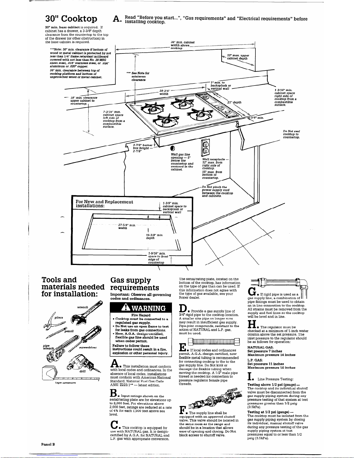
30" Cooktop A
Read “Before you start...“, “
n
installing cooktop.
Gas requirements” and “Electrical requirements” before
30” min. base cabinet is required. If
cabinet has a drawer, a 3-3/8” depth
clearance from the countertop to the top
of the drawer (or other obstruction) in
the base cabinet is required.
***Note: 30” min. clearance if bottom of
wood
of metal cabinet is protected by not
less than l/4” flame retardant millboard
covered with not less than No. 28 JUSG
sheet steel, .015” stainless steel, or .024”
aluminum or .020” copper.
36” min. clearance between top of
cooldng platform and bottom of
unprotected wood or metal cabinet.
*** See Note for
30” min. cabinet
I -3/16” min.
cabinet space
right side of
cooktop from a
combustible
surface.
7-3116” min.
cabinet space
cooktop from a
combustible
Do Not seal
cooJftop to
countertop.
below the
countertop and
centered in the
For New and Replacement
installations:
l-3/8” min.
backsplash or
vertical wall
27-5%” min.
Width
I
19-318” min.
depth
l-9116” min.
space
to
front
edge of et
15”
max. from
bottom of
‘OUT
, DO Not pinch the
Tools and
materials needed
for installation:
tape measurer
Gas supply
requirements
Important: Observe all governing
codes and ordinances.
Fire Hazard
. Cooktop must be connected to a
regulated gas supply.
. Do Not use an open flame to test
for leaks from
gas connections.
. New, A.G.A. design-certified,
flexible gas line should be used
when codes permit.
Failure to follow these
instructions could result in a fire,
explosion or other personal injury.
A
w This installation must conform
with local codes and ordinances. In the
absence of local codes, installations
must conform with American National
Standard, National Fuel Gas Code
ANSI 2223.1” - latest edition.
B
n
Input ratings shown on the
serial/rating plate are for elevations up
to 2,000 feet. For elevations above
2,000 feet, ratings are reduced at a rate
of 4% for each 1,000 feet above sea
level.
C
n
This cooktop is equipped for
use with NATURAL gas. It is designcertified by A.G.A. for NATURAL and
L.P. gas with appropriate conversion.
The serial/rating plate, located on the
bottom of the cooktop, has information
on the type of gas than can be used. If
this information does not agree with
the type of gas available, see your
Roper dealer.
D
n
Provide a aas
SUDD~V
line of
314” rigid pipe to t<e coo-Gob location.
A smaller size pipe on longer runs
may result in insufficient gas supply.
Pipe-joint compounds, resistant to the
action of NATURAL and L.P. gas,
must be used.
E
n
If local codes and ordinances
permit, A.G.A.-design-certified, new
flexible metal tubing is recommended
for connecting cooktop to the to the
gas supply line. Do Not kink or
damage the flexible tubing when
moving the cooktop. A l/2” male pipe
thread is needed for connection to
pressure regulator female pipe
threads.
I’ n The supply line shall be
equipped with an approved shutoff
valve. This valve should be located in
the same
room as
the
range
and
should be in a location that allows
ease of opening and closing. Do Not
block access to shutoff valve.
w If rigid pipe is used as a
gas supply fine, acombination of 111
pipe fittings must be used to obtain
an in-line connection to the cooktop.
All strains must be removed from the
supply and fuel lines so the cooktop
will be level and in line.
H
n
The regulator must be
checked at a minimum of l-inch water
column above the set pressure. The
inlet pressure to the regulator should
be as follows for operation:
NATURAL GAS:
Set pressure 7 inches
Maximum pressure 14 inches
L.P. GAS:
Set pressure 11 inches
Maximum pressure 14 inches
I
n
Line Pressure Testing:
Testing above l/2 psi (gauge) The cooktop and its individual shutoff
valve must be disconnected from the
gas supply piping system during any
pressure testing of that system at test
pressures greater than l/2 psig
(3.5kPa).
Testing at l/2 psi (gauge) The cooktop must be isolated from the
gas supply piping system by closing
its individual, manual shutoff valve
during any pressure testing of the gas
supply piping system at test
pressures equal to or less than l/2
psig (3.5kPa).
Panel B
 Loading...