


Rondish UI DMS-02 v.04
RONDISH DoorWatcher
EASY INSTALL
“STRIP” DOOR MONITOR
Issued 13 June 2017
( For Curbell only)
USER INSTRUCTION

2
CONTENTS
1. EQUIPMENT DESCRIPTION
2. INSTALLATION
3. PROGRAMMING AND SETTING UP
4. SYSTEM OPERATION
5. TECHNICAL SPECIFICATIONS
6. DRAWINGS – INSTALLATION AND SETTING UP
6.1 INSTALLATION GUIDE (001/1 – 001/3)
6.2 ACTIVATING WRISTBAND (001/4)
6.3 QUICK PROGRAMMING GUIDE (001/5 – 001/6)
6.4 USE OF DOOR CONTACTS (001/7 – 001/8)
6.5 QUICK SET-UP FOR DOOR STRIPS 001/9 – 001/11)
7.1 FCC WARNING
7.2 CAUTION OF BATTERY REPLACEMENT
7.3 NOTICE OF CHANGE OR MODIFICATION

3
1.0 EQUIPMENT DESCRIPTION
1.1 Rondish DMS-02 Strip Door Monitor
This unit is a further upgrade of our successful DMS-01 door monitor.
1.1.1 Overview:
Having some enhanced features, the two strip sensors are installed at each side of a door, or set up in an
area and powered from a 12Vdc regulated supply. Power is connected to the free jack socket provided.
These two sensing strips are cabled together and operate jointly to detect an approaching patient wearing
a wristband transmitter. An alarm is then generated that can be reset by the choice of using:
(a) Our wireless remote reset transmitter
(b) Application of our magnetic key at the position indicated by a blue circle
(c) A wired, external “normally open” contact
(d) The alarm reset button on our TTEST-01 test unit
(e) A wireless, or wired security keypad, or card reader
This “reset” function introduces a delay before the alarm becomes active again. Therefore, it can be used
to over-ride/bypass the door monitor alarm while escorting patients through a protected door.
1.1.2 Other functions and interconnections:
(a) Pre-alarm:
A 12Vdc output is provided to operate an electric door lock. These connections are provided at the
top end of the sensor strip units for convenient installation. Upon sensing the approach of a
wristband transmitter, the system can provide the 12Vdc output to temporarily apply the electric lock
and can activate the buzzer to provide a “pre-alarm” warning to the patient. This function is
selectable at J11 on the PCB (factory default = open – which means no sounder).
(b) Door status sensing:
Connections are provided for “normally closed” magnetic door contact. These contacts are used to
detect a door being opened and “arming” the door monitor. In this event, a patient approaching an
open door will immediately trigger a full alarm.
(c) Alarm output:
A “pulsed”, or “steady” 12Vdc alarm output is also provided for operation of external light indicators,
sounders etc. The required mode is selectable at J18 on the PCB (factory default = pins 2-3
“steady”. Adjustable to pins 2-1 = “pulsed”).
(d) Cabled (wired) data transmit option:
Connections are provided for a 4 core telephone type cable for alarms and other signals to be routed
to our central monitor. Connection of this cable at the central monitor is via our junction box (CMJ-01)
and requires a 10K resistor to ground to ensure operation.
(f) Wired reset option.
Connections are provided at the bottom end of the sensor strips for a wired reset function e.g. use of
external keypad, or other external reset function

4
These connections are duplicated at the top of the strip sensors for convenience of cabling,
connection of keypad etc.
1.2 The patient wristband digital transmitter
For door monitoring, there are two main versions of this device:
1. Patient transmitter (TXP-02). This utilizes a watch-style strap, or hospital type with non-removable
(locked) plastic strap.
2. Warden/caregiver door alarm reset/alarm override transmitter (DRB-11).
This patient transmitter is a multi-functional, programmable unit. It can be set up for chosen ID numbers
for groups of users in response to particular customer requirements.
This software controlled transmitter can automatically detect “low battery” condition and send a signal to
alert staff, or caregivers that approximately four (4) weeks of operation remains.
It is very important that a wristband tester unit (TTEST-01) is employed at each site to allow regular staff
checking that the wristbands are transmitting correctly and to indicate any low battery status.
Patient wristbands must be de-activated (password protected) e.g. while held in distributor’s stock to
conserve battery life and re-activated upon issue to a customer. Directions can be found in the Rondish
Transmitter Programming Manual.
2.0 INSTALLATION (refer to drawings 001/1 to 001/11)
Details of the various terminal connections are shown in the drawings 001/1 and 001/3.
2.1 Installation position
This “strip” door monitor is usually installed at the side of a door, as shown in drawing 001/2. Dependent
upon the situation, the user may choose to install the monitors close to the side of the door post on each
side of the door frame. (2 door strips).
If the door has metal posts/frame, ensure that minimum 300mm spacing is allowed between post and
monitor unit.
In exceptional circumstances, especially where short range is required a strip monitor could be installed
on the door itself.
2.2 Preparation
This “strip” monitor unit is designed for mounting utilizing the double sided tape provided.
Caution: Although the plastic housing has holes that could be used for screw fixing, these must not be
used as there is a risk of a short circuit or damage occurring to the lower side of the PCB. After fixing the
plastic strip monitor housing, the PCB inside can slide out of the housing, through the top, or bottom end
to expose the various controls for adjustment.
It is important to try to avoid placing the monitor immediately beside any metal objects, such as metal
doors, electrical cables, metal cabinets etc as these can affect the performance of the door monitoring
system. Following initial setting up of the detection zone, parking of large metal objects within the field of
the system (6/8 ft) such as trolleys, beds, etc should be avoided as these will also have an effect upon the
detection field of the monitor.

5
2.3 Power supply
The 12Vdc ac adaptor output cable should be plugged into the wired-in strip monitor power supply cable
with jack socket and connected to the ac mains supply, when ready to power up the monitor (see Section
3 below – “Setting Up”). If using a magnetic door contact, or electric door lock, connections are
conveniently provided at the top end of the monitor. Note that when using a door lock, an ac adaptor
providing minimum 500mA at 12Vdc is required. Where the two strips are used on either side of a door
both should be connected to the door lock (in parallel) and to the magnetic door contact (in series) if
employed (see diagrams 001/1 and 001/3 for details).
2.4 External devices
An external indicating light and/or external sounder may be connected to the alarm output terminals (refer
to J18 option).
The connections for the door lock and alarm light at the top of the sensor strips have a 12V dc power
source provided and an output that pulls down to 0V via a relay contact (max 1A). Therefore, this only
requires a two-wire connection (refer to drawings 001/1 and 001/3). The rating of the ac adaptor must be
considered when connecting these external devices to the monitor and advice can be obtained from our
technical services division.
Cables for connecting the power supply, door locks, magnetic door contacts, or other external devices
should be kept as short as possible and away from the body of the monitor unit, as these will have an
effect upon field/detection zone of the system.
3.0 PROGRAMMING AND SETTING UP (please refer to drawings in Section 6)
3.1 Programming
For setting up, first slide PCB out of the end opposite to the power cord. Refer to drawing 001/1.
Observe the exposed “Mode” button and door/area ID programming rotary switch.
Note: A single digit “location” code number only needs to be set if there is more than one CMU-02 on the
system and you wish to route this door monitor’s signals to only one particular monitor. In this case, the
CMU-02 would be set for a “matching” single digit (1-7) location number. Otherwise set this door monitor
rotary control to zero (0) so it can be received by any central monitor.
3.1.1 Programming door and area identity numbers
To enter “programming” mode, hold down the “Mode” button for around 3 seconds until three (3) rapid
bleeps with LED flashes are observed, then release the button.
When using two door monitor strips together on one door, it is necessary to program both units with the
same door and area number but different door extension numbers. (Usually 1 & 2)
(a) First set the required Door Identity Number (which particular door).
Use a small screw driver to turn the rotary program switch (0 – 15 positions) and set desired Door Identity
number. Observe that positions A = 10, B = 11, C = 12, D = 13, E = 14, F = 15.
Press the “Mode” button once and the unit will beep/flash once to acknowledge.
(b) Next (while still in “programming” mode), set required Area Number
Turn the rotary program switch to desired area number. (“0” up to “7”, only).
Press the “Mode” button once and the unit will beep/flash to acknowledge.

6
Setting a zero (0) will allow the signal to be accepted by all central monitors.
(c) Now set the door extension number.
As two strips are normally used on a door/area, the left hand strip is usually set to “1” and right hand strip
is set to “2”. Also, to identify which door strip is faulty in the case of a failure being detected by the central
monitor using the self checking procedures.
Press the mode button again.
(d) Set Door Lock Application Time
If electric door lock/s is to be used, you can now set the door lock application time using the same rotary
switch. Note that this switch sets multiples of 5 seconds.
If the door is closed, the lock/s will be immediately applied when a wristband comes within the detection
range of the door monitor and will be released a short time later. No main alarm is triggered in this
situation. Automatic lock release timing is dependent upon the setting of this rotary switch in five second
intervals (approximately).
During the “lock/s applied” time the buzzer can emit a “steady” sound (selectable at J11) as a pre-alarm
warning and to indicate to the patient that the door is locked. For example, setting “3” = 3 x 5 = 15
seconds, or setting “5” = 5 x 5 = 25 seconds etc.
When the lock is released after the set “time-out”, should the door be opened (activating the “normally
closed” magnetic door contacts) and the patient still be inside the detection zone a main alarm will
immediately be triggered. Staff is required to “reset” this main alarm at the particular door/area.
Note: Setting “0” at the rotary switch permanently applies the lock, until the alarm at the monitor is reset.
Now, press the “Mode” button once again and the unit will beep/flash to acknowledge.
A few seconds later, the sensor strip will automatically leave programming mode and return to “normal”
operation.
3.2 Setting up detection zone (refer to drawings 001/9 to 001/11)
In normal alarm operation, this “strip” monitor features an array of red LED lights inside the translucent
cover. A number of LED’s are used to indicate “alarm on” (patient transmitter signal sensed - door
contact open), one LED is used for “signal sensed”. - no alarm (door contact closed).
This transmitter can then be used to test the door monitor range/detection zone. Refer to drawings 001/9
to 001/11 for recommended set-up procedure.
If magnetic door contacts are fitted and during this range setting/test procedure, each time the door
monitor has triggered in response to receiving and sensing the signal from the patient test transmitter
programmed (TXP-02) wristband transmitter, it will either trigger the “pre-alarm” warning or a main alarm
if the door is already opened.
3.3 Finally testing performance of the detection zone (refer to drawing 001/11)
3.3.1 General.
Before the system can be tested, it is first necessary to check the patient transmitter unit (TXP-02) is
switched on using the TTEST-01 test unit.

7
Note:
TXP-02 transmitters can be switched off only by entering “programming mode” and entering the password
as described in the Rondish transmitter programming instructions. Should a particular patient wristband
transmitter not be active (already switched off), the following steps should be followed:
(a) Please refer to drawing 001/4. Use a magnet or Caregiver key (CK-01) to activate the transmitter.
(b) To “switch on” a patient wristband transmitter, place the magnet/Caregiver key in contact with the
patient transmitter body (as indicated in the drawing 001/4) and observe the red LED inside.
(c) Continue to hold the magnet in this position for approximately three seconds. After this period, the red
LED inside the transmitter will “blink” three times. The unit is now activated (switched on) and emitting
signals that can be detected by the door monitor.
If the wristband is then worn and taken into the detection zone, the strip sensors will detect these signals.
Should the range of the detection field need to be adjusted, it is necessary to follow the procedure
described above and selecting a setting resulting in more, or less range, as required.
Notes:
1. These wristbands and door monitors are wireless devices and in practice the actual range for activation
of the door alarm can only be approximate. Therefore, the range will vary slightly from one activation, to
another.
2. The sound level of the sensor strip buzzer can be adjusted by turning VR1 with a small “crossed” screw
driver (clockwise to reduce level - see PCB and diagram 001/1).
3. Any other controls not mentioned I this instruction manual are used for factory settings and should not
be adjusted in the field.
3.3.2 Checking performance
Check the performance of the door monitor by carrying an active patient wristband transmitter and
walking towards the door from a starting point, say 20ft from the sensors.
As the door/area is approached, the wristband signals should be detected by the sensors at the
approximate distance required from the door. If the distance is too great, or too small re-run the
procedure with the set up transmitter as described above but you should note that settings are
approximate only. The important point is to make sure this approximate distance is first set correctly
using the set-up transmitter.
For example, if you set the sensors initially to a “5” (on the rotary switch) sensitivity setting and you find
the range could be set longer (remember set the range as long as the site will allow you too), you should
try a “4” setting since this is a more sensitive setting and therefore has longer range.
If you require a shorter range then use a ”6” setting (less sensitivity = lower range) and so on.
Note: The number actually indicates the signal level during set-up. Therefore a higher number indicates
a higher signal is required to be received from the transmitter and therefore shorter range.
As you are using two sensor strips, you have to set-up each strip in turn. Usually they will be set to the
same sensitivity level “number”. Due to variations on each site, they may need be set differently to suit
the requirement.

8
3.3.3 Wristband low battery auto detect and report
Each patient wristband (TXP-02) will detect “low battery” and automatically transmit a signal to be
indicated by an LED on the door monitor. This “low battery” condition will be also indicated on our TTEST
staff wristband tester (if held within 1.5m of the wristband), CMU-02 central monitor, or HPCON-01
wireless universal remote display equipment etc.
When “low battery” is reported, there are approximately four weeks of reliable life remaining for the
particular wristband.
It is recommended that every door monitor site employs our TTEST wireless tag reader to allow regular
staff checks of wristband signals and battery condition.
4.0 SYSTEM OPERATION
This door monitor may be used for normally open or normally closed doors.
4.1 Normally open door
(No door contact fitted, or using sensors fitted in a corridor area)
If a patient wearing the wristband enters the detection zone, a full alarm will immediately be triggered.
This is indicated by the red LED’s flashing and the sounder on – “steady while any door lock is on and
“pulsing” after door lock time-out. Refer to J11.
An activated alarm will be transmitted to be received by a wireless central monitor, or other display and
indication device (if employed). The risk of any unwanted alarms can be reduced by fitting a PIR detector
(see drawing 001/8).
This alarm can be reset remotely by a care attendant approaching the door and pressing the button on a
wireless reset transmitter, entering the correct code on the wireless keypad or by presenting the optional
magnetic proximity key at the point indicated on the door monitor unit (blue circle). It can also be reset (if
within range) by using our TTEST staff tester and control unit.
4.2 Normally closed door with pre-warning (see drawing 001/7)
A magnetic door contact can be fitted. If a patient wearing a wristband enters the detection zone, the
local sounder is activated (pre-alarm warning) and if fitted the door lock energized (refer to J11 option).
While the door remains closed, the door monitor does not activate any main alarm.
Should the door be opened (following the pre-selected lock/s applied time), an alarm will immediately be
activated and transmitted to a central monitor, or other display and indication device to be indicated as a
full alarm.
Upon receiving the pre-warning, the patient should retreat from the sensor detection zone. After a short
period the door lock will be released (unless set to always be “on” i.e. time setting zero (“0”)). If the door
is now opened no alarm is activated provided the patient is no longer within range.
4.3 Full alarm reset/bypass
A full alarm at the door monitor can be reset by a caregiver using either the remote wireless reset
transmitter, magnetic proximity key etc. This reset transmitter may also be used to “bypass” the door
alarm for a preset period of time to allow a patient wearing a wristband to be escorted through a protected
door. Other devices may be employed to reset/bypass the door alarm (refer to “Reset” terminal on
connector shown in drawing 001/1 and 001/3).

9
4.4 Functionality
The door monitor unit incorporates a wireless “data” receiver that detects and reads the identity of each
transmitter. It can simultaneously receive a number of transmitters passing through the detection field.
Separate field strength receivers are built into the monitor unit to detect and analyze the strength of
signals emitted from nearby wristband transmitters and therefore the approximate distance from the
doorway.
4.5 Patient transmitter programming and battery saving
As standard procedure, patient wristbands are supplied pre-programmed with factory standard ID
numbers and with the transmitter de-activated (switched off) to conserve the battery.
A simple procedure for activation (switch on) of a “dormant” wristband transmitter is described in section
3.3.1 above and in drawing 001/4.
Programming information describing how to set individual ID numbers and/or de-activate (switch off) the
wristband transmitter is provided in the Rondish Transmitter Programming Instruction Manual.
5.0 TECHNICAL SPECIFICATIONS
5.1 Door monitor unit
1) Operating Frequency: 433.92MHz
2) Operating Power
(a) Current for door monitor, but no door lock, or flash light <100mA
(b) Current for door monitor with one door lock and flash light < 400mA
(c) Ac mains adaptor (for regional ac voltage input): Regulated 12Vdc 500mA (UL/CE approved).
3) Magnetic door contact, or PIR connection: Uses “normally closed”, volt-free magnetic contact
between the “Contact” and 0V terminals.
4) Maximum rating for relay output contacts: 1A (e.g. for door lock)
5) Adjustable buzzer volume (Internal)
6) Automatic “Out Of Range” and “Interference” detection with alert (used with Central Monitor)
7) Dimensions of housing: 720mm x 30mm x 20mm.
8) Narrow band receiver to help prevent interference.
5.2 Patient wristband transmitter (TXP-02)
1) Radio frequency 433.92MHz. Narrow band digital wireless
2) Operating Range: Adjustable at door monitor (typical 2-8 meters)
3) Periodic digital transmissions:
4) Extended battery life.

(a) Battery saving activate/de-activate function using a magnet or Caregiver key (CK-01)
(b) Normal use (always on): Typically 1 year
(c) Continuous out-of-service “shelf life”: of the order of 5 years (Typically 10% battery
life reduction per year).
5) Low battery detection and alert
6) Unique identity coding
7) Unit programming function (password protected)
8) Error checking (check sum)
10

6. DRAWINGS – INSTALLATION AND SETTING UP
6.1 INSTALLATION GUIDE (PAGE 1 OF 3)
Magnetic contacts for optional
Common +12Vdc power
Optional wired
reset connection
(keypad, card reader etc)
RONDISH STRIP DOOR MONITOR
DMS-02
12Vdc 500mA regulated ac mains adaptor, or PSU
(regional ac mains voltage to apply)
Door zone range setting, door lock timing, door
identity and area coding program
(16 way rotary switch)
Holes for
cable tie
Cable entry
port
Optional magnetic door
contacts connection
Common power 0V
NOTE:
Use standard Rondish ac adaptor (ACCE-04,) or power supply of sufficient capacity
if door locks are to be connected.
For detailed wiring connections, refer to drawing 001/3
+12V
RESET
CONTACT
0V
Mode button for
programming
Red alarm and set-up LED indicators
(inside white translucent cover)
J11
caregiver magnetic key alarm
Sounder level adjust
Common 0V
Not used
PCB
J18
reset
Translucent plastic housing
Optional wired
data connection
(J15 Tx, or wired)
(keypad, card reader etc)
(white colour)
Alarm contact output
(0Vdc J15 flash/steady)
Optional magnetic door
contacts connection
+
0V
SW1
N/C
TX
RESET
Optional electric door
lock connection
Optional wired
reset connection
J15
ALARM
(COM)
CONTACT
LOCK
0V
+12V
+12V
Common +12Vdc power
Standard adaptor
plug (12Vdc)
Cable tie
(loop cable through for strength)
PVC Sheathed
two core flexible cable
(black colour)
Common power 0V
TITLE
MODEL No.
DRAWING No.
Optional free socket and cable
for ac adaptor connection
(fitted as standard)
Removable (slide-off)
cover
Strip Door Monitor unit
DMS-02
001/1V2

RONDISH STRIP DOOR MONITOR
6.1 INSTALLATION GUIDE (001/1 – 001/3)
Note:
DMS-02
Optional wired flashlight/sounder. Use +12V common.
(0Vdc J18 flashing/steadyalarm contact output)
DMS-02
Optional "NC" magnetic door
contacts (for double doors
connect in "series")
Set J11 for pre-alarm door lock
(for double doors connect in "parallel")
(Follow manufacturer's installation instructions)
Optimum position for DMS-02
Centre = approx 1300mm AFFL
1300mm
AFFL
Optional electric door lock
12V dc power
Otional wired data
J15
DMS-02
alarm reset point (blue circle)
ac mains adaptor
12Vdc
500mA regulated
Wireless remote caregiver
alarm reset and bypass transmitter
(TXR-02)
Alternative magnetic
(caregiver key)
TITLE
MODEL No.
Strip Door Monitor
DMS-02
DRAWING No. 001/2V3
Patient wireless wristband
transmitter. Can be programmed
for set-up and range testing
(TXP-02(LP))
In this case, the sensor strips should be mounted near to the door post.
If metal door posts allow minimum 300mm clearance.
Please refer to the User Instructions for setting up.
INSTALLATION GUIDE (PAGE 2 OF 3)

RONDISH STRIP DOOR MONITOR DMS-02
6.1 INSTALLATION GUIDE (001/1 – 001/3)
NOTE: Power, Lock and Magnertc Door Contact connections are duplicated at both ends of
strip sensor units unit for convenience of connection.
12Vdc 500mA regulated
power input
12Vdc (1amp max) output to energise door lock (optional)
Connect in parallel
(for two door strips and/or
two door locks)
Connect 12V power supply
in parallel (for two door strips)
Refer to J11
0V 12VContact
Alarm
Lock +12V
(Com)
0V N/C TX Reset
Please refer to User Instruction manual
Magnetic door contacts(optional)
Electric door lock
Connect magnetic contacts in series
(for two door strips and/ordouble doors)
Refer to J15
TITLE
12Vdc (1 amp max) alarm contact output for flash
light, or other indicating device (optional)
Wiring for door monitor strips
(Contact, keypad, card reader etc)
Please refer to drawing 001V2
for alternative Reset connection
Reset
Typically 4 core telephone type cable
Wired data Tx
to CMU-02
via
CMJ-01 junction box
MODEL No.
DRAWING No.
DMS-02
001/3V2
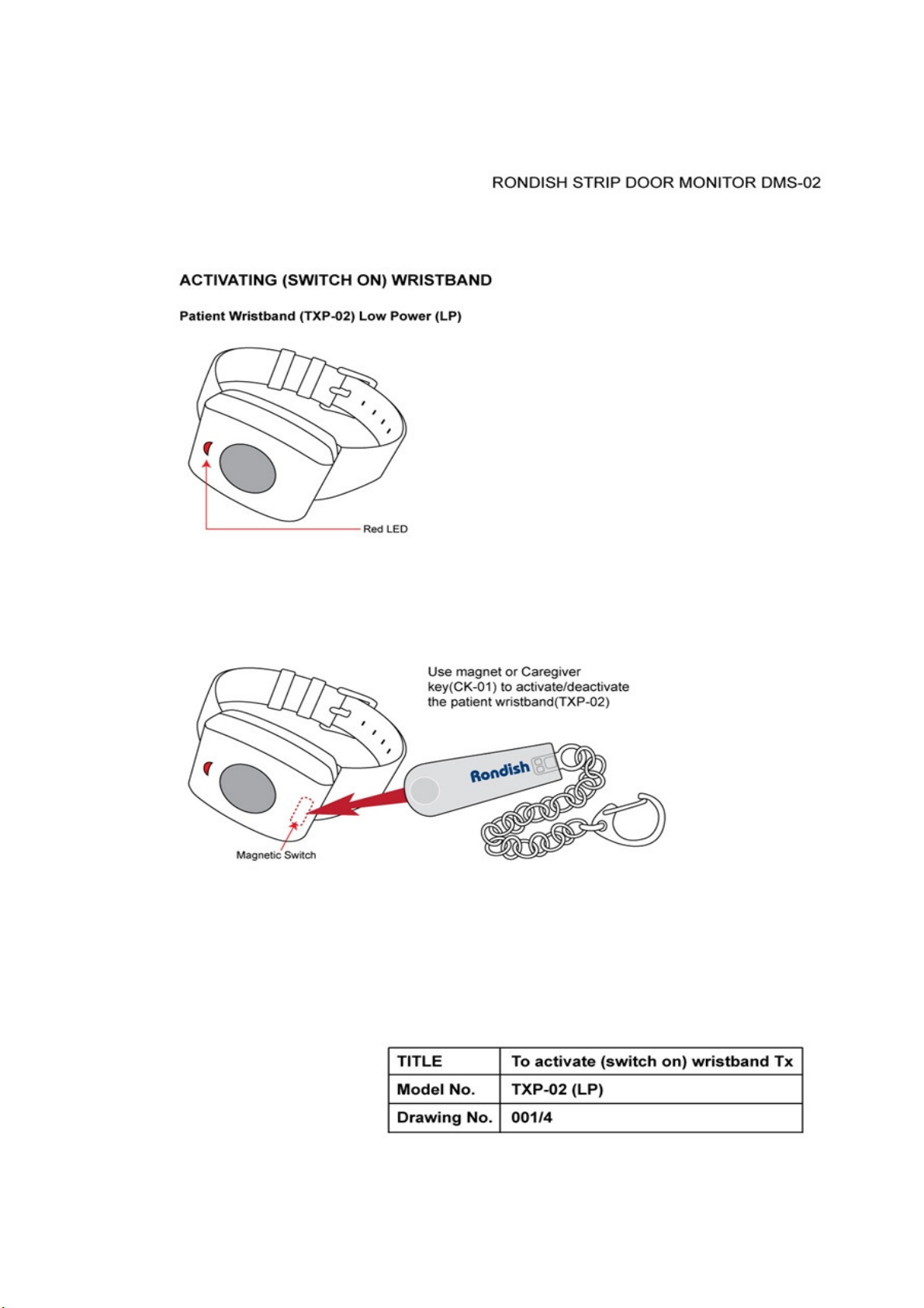
6.2 ACTIVATING WRISTBAND (001/4)

RONDISH STRIP DOOR MONITOR DMS-02
6.3 QUICK PROGRAMMING GUIDE (001/5 – 001/6)
DOOR MONITOR STRIP : QUICK PROGRAMMING GUIDE
Introducton:
Step 1:
Step 2:
On the door strip monitor you can program the following items
1. Set door number on rotary switch 0-15(F) Identifies door number at Central Monitor
NOTE: When two door monitor strips are
used same door it should be set the same
to allow to work together
2. Set area code/number on rotary switch 0-7 Must match the particular Central Monitor
setting. Refer to CMU-02 User Instructions.
Set to zero if want to receive by all CM.
3. Set door "extension" number 0-6 When two, or more monitor strips are used
for the same door. Sets left side to one
and right side to two and so on
by multiple door strips with same door number.
set to zero if only one door strip used.
4. Set door lock/s timer 0-F Sets door lock/s applied timer in intervals
of 5 seconds. NOTE: setting "0" = no
time-out (continuous application of locks
during alarm).
Remove cap at bottom of strip unit at opposite end to magnetic caregiver key alarm reset point
(blue circle).
Slide off cap and slide
out PCB at bottom of monitor strip
Rotary programming switch
Programme mode button
(press and hold for 3 seconds until "beep" heard)
TITLE
MODEL No.
DRAWING No.
Quick Programming Procedure
DMS-02
001/5

Rondish Door Monitoring System DMS-02
6.3 QUICK PROGRAMMING GUIDE (001/5 – 001/6)
DOOR MONITOR QUICK PROGRAMMING PROCEDURE
Testing after programming a door monitor
NOTE:
Step 3:
(i) Press and hold programme mode button until you hear three(3) fast beeps.
Set door number on rotary programming switch.(1-F)
(ii) Press mode button until you hear one (1) "beep".
Set area code number e.g. "0" will be received by any Central Monitor.
(iii) Press and hold programme mode button until you hear two (2) beeps..
Set door "extension" code (required when two, or more monitor strips are used for one
door). This code is set e.g. on the first strip monitor as 1 and a second strip on the same door as 2.
note. Set to zero if one unit or used with older versions of door monitors.
(iv) Press and hold programme mode button until you hear three (3) beeps.
Set door lock time number. These are set at 5 second intervals - example 3=15 seconds
5 = 25 seconds, F(15) = 75 secs. Note. 0 = always on in alarm.
(v) Press program button until hear 2 beeps and after a few seconds unit will
beep 4 times and exit program mode.
You now need to test into a central monitor by setting off an alarm with a
wristband and checking door number dsiplayed. If central monitor does not receive the alarm you may
need to check the area code is set correctly. (set central monitor to zero area code and try again
to test if this is the problem).
If the area code on the central monitor is set differently to
the door monitor (unless one is zero) it will not receive the signal.
If two door monitors are programmed to the same door number i.e. on the same door and
you find the signal is not reliable to the central monitor especially when a door contact is used and during a
alarm reset this probbaly means the door extension number has not been set correctly. Try reprogramming
the units ensuring these are set to different numbers. (eg 1, 3, etc)
Check the door lock time (buzzer steady on ) is correct (usually set to 15 secs) with a watch etc.
That concludes the tests.
TITLE
MODEL NO.
DRAWING NO.
Quick Programming Procedure
DMS-02
001/6

RONDISH STRIP DOOR MONITOR DMS-02
6.4 USE OF DOOR CONTACTS (001/7 – 001/8)
USING DOOR CONTACTS, OR PIR TO AVOID FALSE
ALARMS
1. Magnetic contacts
Floor 2
NOTE:
Due to the nature of electromagnetic signals and in
operating wireless door monitoring systems, it should
be noted that while a very high level of accuracy is
achieved, 100% accuracy can not be guaranteed.
Magnetic contact closed (door monitor disabled).
Refer to J11
Door closed: pre-alarm sounds constant tone for
preset time (e.g. 15 seconds).
Door lock will operate (if fitted), but no full alarm
while door remains closed.
Floor 1
Floor slab
Magnetic door contact open (door monititor "armed").
If door opened, have instant full alarm.
Note: For full alarm, the alarm tone is activated, the door
monitor LEDs flash and a wired TX signal can be sent to the
Central Monitor (if employed).
NOTE:
PIR detector may be used as an alternative
to the magnetic door contact, or if no door/open area
TITLE
Multi-door monitor/multi-floor
MODEL No.
DRAWING No.
DMS-02
001/7V3

6.4 USE OF DOOR CONTACTS (001/7 – 001/8)
USING DOOR CONTACTS, OR PIR TO AVOID FALSE
ALARMS
Fitting a PIR detector can help reduce unwanted alarms in a close environment.
For example, in a corridor with no doors, or open door operation
Connect PIR to strip monitor magnetic door contact terminals
Wire PIR 12V power in parallel with door strip power terminals
Rondish Door Monitoring System DMS-02
PIR Detector
In this case, alarm is only allowed when the PIR is triggered.
NOTE: This is useful to reduce unwanted alarms when wristbands are carried near
to the door monitors e.g. on the other side of a wall, or (less likely) on a floor above, or below.
NOTE:
Due to the nature of electromagnetic signals and in
operating wireless door monitoring systems, it should
be noted that while a very high level of accuracy is
achieved, 100% accuracy can not be guaranteed.
TITLE
MODEL No.
DRAWING No.
Corridor/no door operation
DMS-02
001/8V3

RONDISH STRIP DOOR MONITOR DMS-02
6.5 QUICK SET-UP FOR DOOR STRIPS 001/9 – 001/11)
Strip Door Monitor quick setup procedure
Introducton:
NOTE:
Step 1:
Step 2:
Step 3:
Step 4:
Step 5:
Setting up the DMS-02 strip door monitor has been made easy using the TXP-02(LP) patient tansmitter
for range test.
Do not press the program button on the monitor unit.
Also, please note that maximum range of the unit (rotary switch at zero) is around 5-8 meters.
You should first program the door strip monitors before setting up.
Set rotary switch on monitor/s to mid-point (7). An LED should be "blinking" slowly to indicate "ready".
Fit TXP-02(LP) transmitter unit on wrist and ensure it is switched on using the magnet/Caregiver key (CK-01)
(Please refer to drawing 001/4). If magnetic contacts are fitted and standing near to the door,
you should see another LED flashing to indicate "signal detected".
Move away from the door monitor until this flashing "signal detected" LED stops completely. Next, move back
towards the door until this signal LED flashes again. This point indicates the approximate set up detection
range for the door monitor installation.
If you require more range (longer distance from the door), reduce the setting of the monitor rotary
switch to 6. For less range (shorter distance from door), set the rotary switch to 8.
Continue to adjust the setting of the rotary switch/s and repeat testing until the required range is
obtained.
You may now close the door monitor housing and range setup is complete.
TITLE
MODEL No.
Quick Setup Procedure
DMS-02
DRAWING No.
001/9V3

RONDISH STRIP DOOR MONITOR DMS-02
6.5 QUICK SET-UP FOR DOOR STRIPS 001/9 – 001/11)
Wearing the range test
transmitter wristband(TXP-02(LP)),
walk slowly towards the
door monitor
For setting up detection zone/range, please refer to User Instruction (Page
7 section 3.2)
(a) start with door zone range rotary switch to a mid-way setting (7)
(b) Using the range test transmitter, walk towards the door monitor
(c) When the LEDs flash and a beep is heard, the monitor has detected the
signal from the test transmitter. The distance between transmitter and door
monitor at that time indicates approximate door zone range setting.
note. Only 1 beep (the first) indicates an alarm condition.
higher number = lower range/smaller detection zone.
(d) Using a patient wristband, the door monitor alarm will be triggered. The
electronic coding of the test transmitter indicates range, but does not trigger any
alarm.
Note: Please refer to drawing 001/5. Adjust rotary switch and repeat range test
as necessary until required door zone performance is obtained.
TITLE
Set up the Strip Door Monitor
MODEL No.
DRAWING No.
DMS-02
001/10V3

RONDISH STRIP DOOR MONITOR DMS-02
6.5 QUICK SET-UP FOR DOOR STRIPS 001/9 – 001/11)
DOOR STRIP QUICK SET-UP
Rondish Patient Transmitter
(TXP-02(LP))
(a) Switch on/activate a patient tracking wristband by refering to the User Instruction (Page 8
section 3.3.1)
(b) Refer to USER INSTRUCTIONS section 3.0. W earing a wristband on the wrist, test by walking towards
the door/zone from different directions. If set correctly, the door monitor should alarm before you
reach the door.
Note: Settings are approximate only, so repeat set-up and test again, if necessary.
TITLE
MODEL No.
DRAWING No.
Test the Patient Transmitter
DMS-02
001/11V3

7.1 Warning:
This device complies with Part 15 of the FCC Rules. Operation is subject to the following two
conditions: (1) this device may not cause harmful interference, and (2) this device must accept any
interference received, including interference that may cause undesired operation.
NOTE: This equipment has been tested and found to comply with the limits for a Class B
digital device, pursuant to Part 15 of the FCC Rules. These limits are designed to provide
reasonable protection against harmful interference in a residential installation. This
equipment generates uses and can radiate radio frequency energy and, if not installed and
used in accordance with the instructions, may cause harmful interference to radio
communications. However, there is no guarantee that interference will not occur in a
particular installation. If this equipment does cause harmful interference to radio or
television reception, which can be determined by turning the equipment off and on, the
user is encouraged to try to correct the interference by one or more of the following
measures:
-- Reorient or relocate the receiving antenna.
--Increase the separation between the equipment and receiver.
--Connect the equipment into an outlet on a circuit different from that to which the receiver
is connected.
-- Consult the dealer or an experienced radio/TV technician for help.
7.2 CAUTION:
RISK OF EXPLOSION IF BATTERY IS REPLACED BY AN INCORRECT TYPE.
DISPOSE OF USED BATTERIES ACCORDING TO THE INSTRUCTIONS.
7.3 Notice
Changes or modifications are not expressly approved by the party responsible for
compliance could void the user's authority to operate the equipment.
11
 Loading...