

Rolsen RL-30S10 Service Manual
COLOR TFT-LCD TV
SERVICE MANUAL
MODEL : RL-30S10
CAUTION !!
BEFORE SERVICING THE TFT-LCD TV,
READ THE SAFETY PRECAUTIONS IN THIS MANUAL.
30INCH LCD SERVICE MANUAL
PAGE:1

CONTENTS
Contents ------------------------------------------------------------------------ 2
Safety Precautions ---------------------------------------------------------- 3
Servicing Precautions ------------------------------------------------------ 4
Specifications ----------------------------------------------------------------- 5
Control Descriptions -------------------------------------------------------- 10
External In/Out Ports ------------------------------------------------------- 13
Adjustment -------------------------------------------------------------------- 14
Block Diagram ---------------------------------------------------------------- 19
Schematic Diagram --------------------------------------------------------- 20
Wave Form --------------------------------------------------------------------- 21
Troubleshooting -------------------------------------------------------------- 32
Replacement Parts List ---------------------------------------------------- 37
PCB Layout -------------------------------------------------------------------- 47
Exploded View ---------------------------------------------------------------- 52
30INCH LCD SERVICE MANUAL
PAGE:2

SAFETY PRECAUTIONS
!! Important Safety Notice !!
Many electrical and mechanical parts in this chassis have special safety-related
characteristics.
These parts are identified by in the Schematic Diagram and Replacement Parts List.
It is essential that these special safety parts should be replaced with the same components
as recommended in this manual to prevent Shock, Fire, or other Hazards.
Do not modify the original design without permission of manufacturer.
Leakage Current Hot Check (See below Figure)
Plug the AC cord directly into the AC outlet.
Do not use a line Isolation Transformer during this check.
Connect 1.5K/10watt resistor in parallel with a 0.15uF capacitor between a known good earth
ground (Water Pipe, Conduit, etc.) and the exposed metallic parts.
Measure the AC voltage across the resistor using AC voltmeter with 1000 ohms/volt or more
sensitivity.
Reverse plug of the AC cord into the AC outlet and repeat AC voltage measurements for each
exposed metallic part. Any voltage measured must not exceed 0.75 volt RMS, which is,
corresponds to 0.5mA.
In case any measurement is out of the limits specified, there is possibility of shock hazard and
the set must be checked and repaired before it is returned to the customer.
Leakage Current Hot Check circuit
30INCH LCD SERVICE MANUAL
PAGE:3

SERVICING PRECAUTIONS
CAUTION!!
Before servicing receivers covered by this service manual, read and follow the SAFETY
PRECAUTIONS on page 3 of this publication.
General Servicing Precautions
1.Always unplug the receiver AC power cord from AC power source before;
ⓐRemoving or reinstalling any component, circuit board module or any other receiver assembly.
ⓑDisconnecting or reconnecting any receiver electrical plug or other electrical connection.
ⓒConnecting a test substitute in parallel with an electrolytic capacitor in the receiver.
CAUTION!! A wrong part substitution or incorrect polarity installation of electrolytic capacitors
may result in an explosion harzard.
2.Do not spray chemicals on or near this receiver or any of its assemblies.
3.Do not defect any plug/socket voltage interlocks with which receivers covered by this service
manual might be equipped.
4.Always connect the test receiver ground lead to the receiver chassis ground before
connecting the test receiver positive lead. Always remove the test receiver ground lead last.
5.Do not connect the test fixture ground strap to power supply heatsink in this receiver
Electrostatically Sensitive(ES) Devices
Some semiconductor(solid state) devices can be damaged easily by static electricity. Such
components commonly are called Electrostatically Sensitive(ES) Device.Examples
Circuit Board Foil Repair
Excessive heat applied to the copper foil of any printed circuit board will weaken the adhesive
that bonds the foil to the circuit board causing the foil th separate from or “lift-off” the board.
The following guidelines and procedures should be flollowed whenever this condition is
encountered.
At IC Connections
To repair a defective copper pattern at IC connections use the following procedure to install a
jumper wire on the copper pattern side of the circuit board.(Use this technique only on IC
connections.)
1.Carefully remove the damaged copper pattern with a sharp knife.(Remove only as much
copper as absolutely necessary.)
2.Carefully scratch away the solder resist and acrylic coating(if used) from the end of the
remaining coopper pattern.
3.Bend a small “U” in one end of a small guage jumper wire and carefully crimp it around the IC
pin.
4.Route the jumper wire along the path of the out-away copper pattern and let it overlap the
previously scraped end of the good copper pattern. Solder the overlapped area and clip off any
excess jumper wire.
30INCH LCD SERVICE MANUAL
PAGE:4

SPECIFICATIONS
Note: Specifications and others are subject to change without notice for improvement.
1.Scope.
This document is the specification of 30” TFT-LCD Color TV.
2.Power
1) Power requirement DC 24V / 6.0A
2)AC / DC Adapter.
Input Frequency : 50/60㎐
Input Voltage : AC 100V ~ AC 240V (±10%)
Output Voltage : DC 24V
3)Power cord
Use UL listed and CSA certified detachable power cord type ;SVT, 3-conductors, 18AWG
For AC 120V area. Use VDE listed detachable power cord type ;HO5VV-F, 3-conductors,
18AWG for AC 220~240V area.
3.Tuning system
FS, 181 Channel
4.Sound output
10W+10Wrms Stereo (Max)
20W+20Wrms Stereo (Max)
5.Antenna input impedance
VHF / UHF at 75ohm
6.OSD Type (On Screen Display)
Windows type (Center)
7.External in/output
Wofer Sound out,SCART1/VIDEO, SCART2/COMPONENT, S-Video, AV Sound In,
Head Phone, PC-Souns In, PC-Analog, PC-Digital
8.Function
CATV/Hyper band
Auto Program
Manual Program
Auto Sleep
Quick view
ACMS(Auto channel Memory System)
PSM(Picture Status memory)
SSM(Sound Status memory)
PIP(PICTURE I RICTURE)
ARC(ASPECT RATIO CONTROL)
30INCH LCD SERVICE MANUAL
PAGE:5
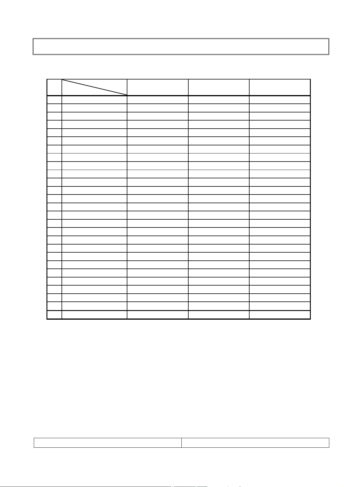
9.Receiving RF TV system
NO
Model System
1 PAL-B
2 PAL-G
3 PAL-I, I /I
4 PAL-D
5 PAL-K
6 SECAM-B
7 SECAM-G
8 SECAM-D
9 SECAM-K
10 SECAM-K1
11 SECAM-I (6.0)
12 NTSC-3.58 / 4.5
13 NTSC-3.58 / 5.5
14 NTSC-3.58 / 6.0
15 NTSC-3.58 / 6.5
16 NTSC-3.58 / 4.5(5.0)
17 NTSC-4.43 / 5.5
18 NTSC-4.43 / 6.0
19 NTSC-4.43 / 6.5
20 PAL 5.5 / 60Hz
21 PAL 6.0 / 60Hz
22 PAL 6.5 / 60Hz
23 SECAM 5.5 / 60Hz
24 SECAM 6.0 / 60Hz
25 SECAM 6.5 / 60Hz
26 SECAM L / L' X
TOTAL SYSTEM 25
SPECIFICATIONS
RL-30S10 / /
○/ /
○/ /
○/ /
○/ /
○/ /
○/ /
○/ /
○/ /
○/ /
○/ /
○/ /
○/ /
○/ /
○/ /
○/ /
○/ /
○/ /
○/ /
○/ /
○/ /
○/ /
○/ /
○/ /
○/ /
○/ /
//
//
30INCH LCD SERVICE MANUAL
PAGE:6
SPECIFICATIONS
y
y
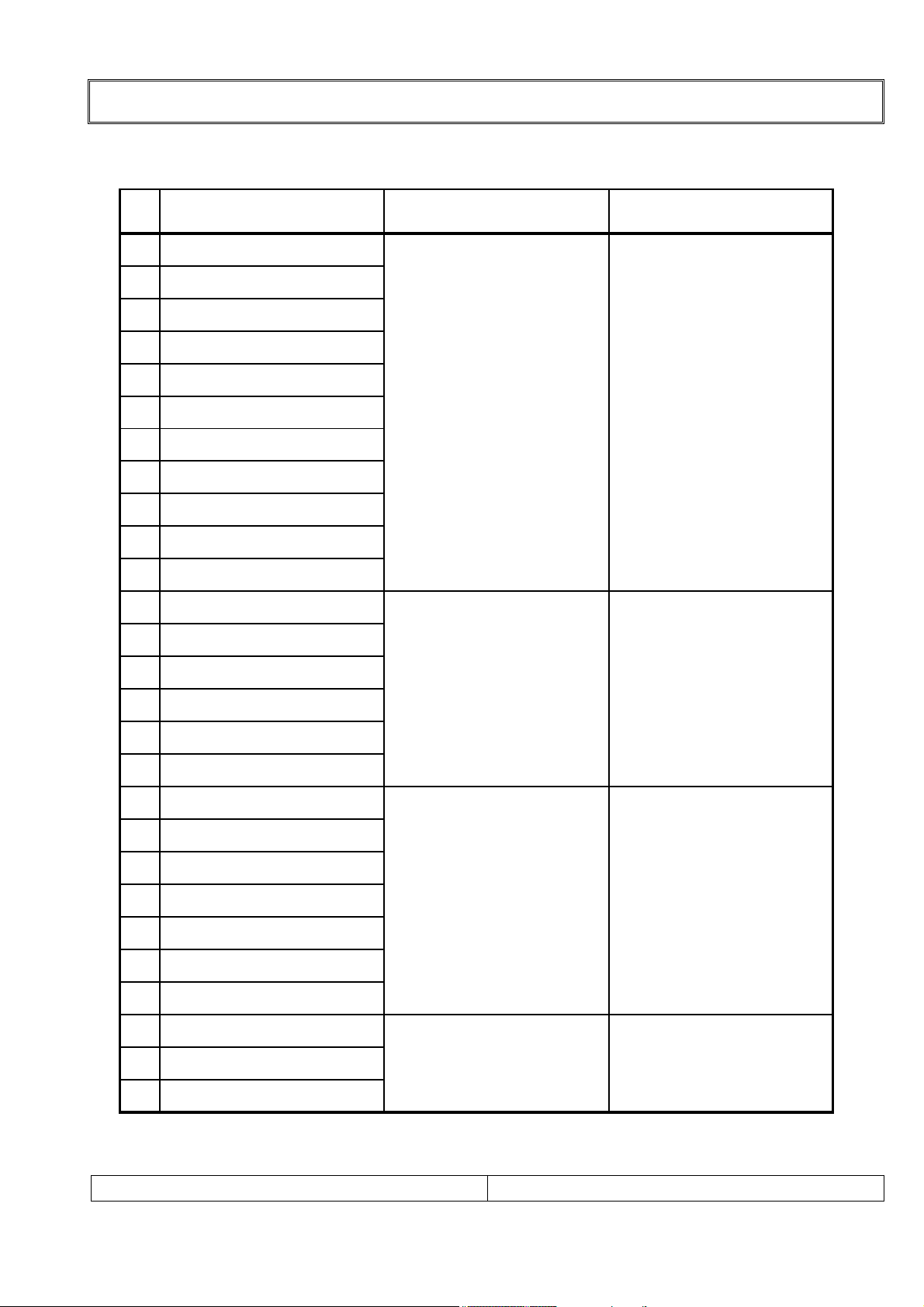
10.Receiving function & channel
NO Receiving System Function Receiving Channel
1 PAL-B
2 PAL-G
3 PAL- I, I / I
4 PAL-D
5 PAL-K
6 SECAM-B
7 SECAM-G
8 SECAM-D
9 SECAM-K
10 SECAM-K1
Reception of broadcast
and play-back for Video
Tape Recorder
NTSC-M (JAPAN) : 1-12
NTSC-M (JAPAN) : 13-62
VHF Band
NTSC-M (US) : 2-13
UHF Band
NTSC-M (US) : 14-78
11 NTSC-M
12 SECAM-L / L'
13 NTSC-4.43 / 5.5
14 NTSC-4.43 / 6.0
15 NTSC-4.43 / 6.5
16 SECAM-I (6.0MHz)
17 SECAM-L (VIDEO IN)
18 NTSC 3.58 / 4.5MHz / 50Hz
19 PAL 5.5MHz / 60Hz
20 PAL 6.0MHz / 60Hz
21 PAL 6.5MHz / 60Hz
22 SECAM 5.5MHz/60Hz
23 SECAM 6.0MHz/60Hz
24 SECAM 6.5MHz/60Hz
Play-back for special
Video Tape Recorder
Play-back for special
Video Tape/Video disk
player
NTSC 3.58/4.5MHz/60Hz onl
NTSC 3.58/4.5MHz/60Hz onl
25 NTSC-3.58 / 5.5MHz
26 NTSC-3.58 / 6.0MHz
27 NTSC-3.58 / 6.5MHz
30INCH LCD SERVICE MANUAL
Play-back for special
Video Tape Recorder
PAGE:7
SPECIFICATIONS
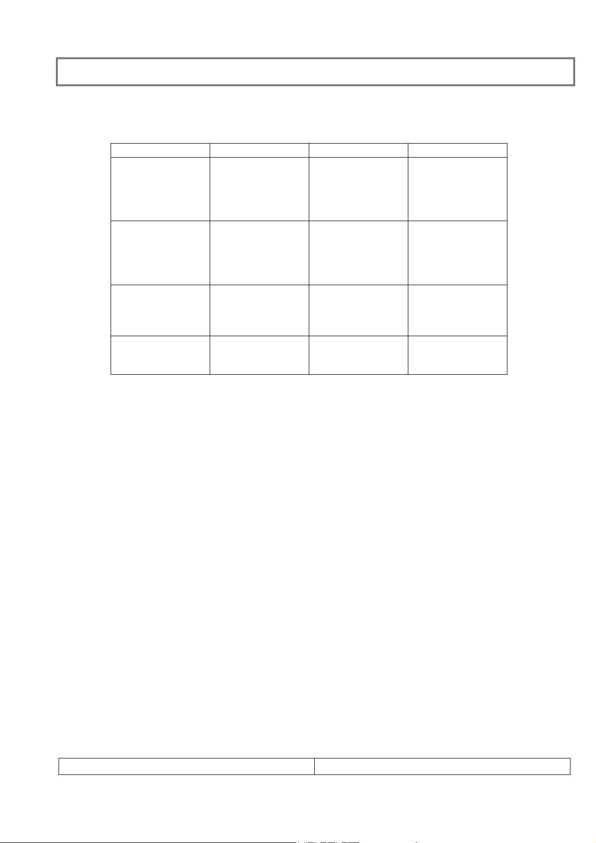
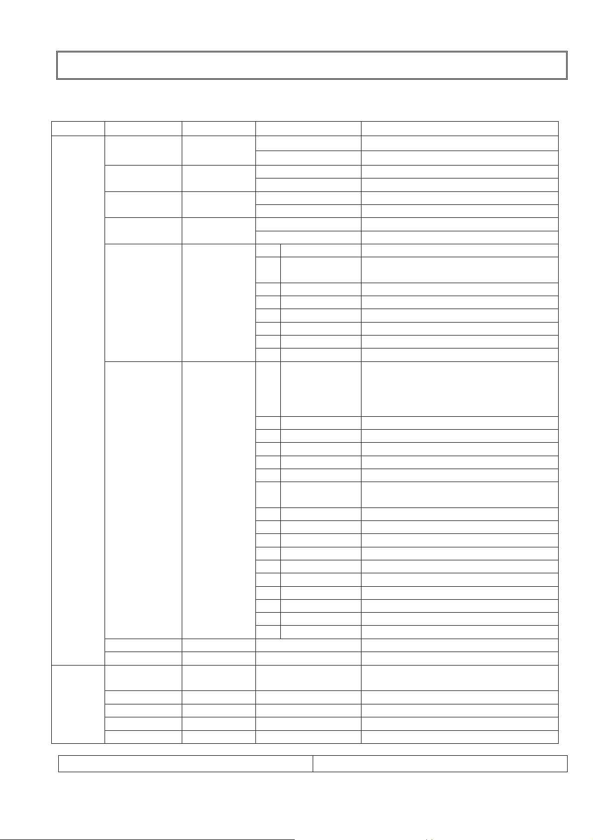
11. PC/DTV Mode Scan Frequency & Timing
1)Scan Freq : H: 15 ~ 110 kHz / V : 56 ~ 85㎐
2)Preset Timing Chart
Mode Resolution H-Freq(Khz) V-Freq(Khz)
640x480
640x480
VGA
SVGA
XGA
D-TV
640x480
640x480
720x400
800x600
800x600
800x600
800x600
800x600
1024x768
1024x768
1024x768
1024x768
1920x1080i
1280x720i
720x480p
Note!! :
ⓐ If the set is cold, there may be a small “flicker” when the set is switched on. This is
Normal, there is nothing wrong with the set.
ⓑ if possible, use the VESA 640x480 PC video mode to obtain the best image quality for
your LCD TV. If used under the other resolutions, some scaled or processed pictures may
appear on the screen.
ⓒ some dot defects may appear on the screen, like Red, Green or Blue spot. However, this
will have no impact or effect on the monitor performance.
31.5KHz
37.9KHz
37.5KHz
43.3KHz
31.5KHz
35.1KHz
37.9KHz
48.1KHz
46.9KHz
53.7KHz
48.4KHz
56.5KHz
60.2KHz
68.7KHZ
33.8KHz
45KHz
31.5KHz
60Hz
72Hz
75Hz
85Hz
70Hz
56Hz
60Hz
72Hz
75Hz
85Hz
60Hz
70Hz
75Hz
85HZ
60Hz
60Hz
60Hz
30INCH LCD SERVICE MANUAL
PAGE:8

SPECIFICATIONS
12. TFT – LCD Panel Character
1) Feature
Size : 29.53 inches (750.062mm) diagonal
LCD Type : Color Active Matrix TFT
Pixel Pitch : 0.5025mm x 0.1675 x RGB
Pixel Format : 1280 horiz. By 768 vert. Pixels RGB strip arrangement
Active Video Area : 643.2mm(H) x 385.92mm(V)
Surface treatment : Hard coating(3H) Anti-glare treatment of the front polarizer
Response Time(Typ) : 25Ms (Typ)
Viewing Angle<CR≥10> : Hor [Left/Right] Æ 85Deg (Typ) / 85Deg (Typ),
Ver [High(Top)/Low(Bottom)] Æ 85Deg (Typ) / 85Deg (Typ)
Luminance(Typ) : 450 cd/㎡(Typ)
Contrast Ratio(Typ) : 350(Typ)
Display Color : 16.7M Color
Back Light : 16 CCFL
30INCH LCD SERVICE MANUAL
PAGE:9
CONTROL DESCRIPTIONS
All the function can be controlled with the remote controller.
Some functions can also adjusted with the buttons on the controls on the TV front panel.
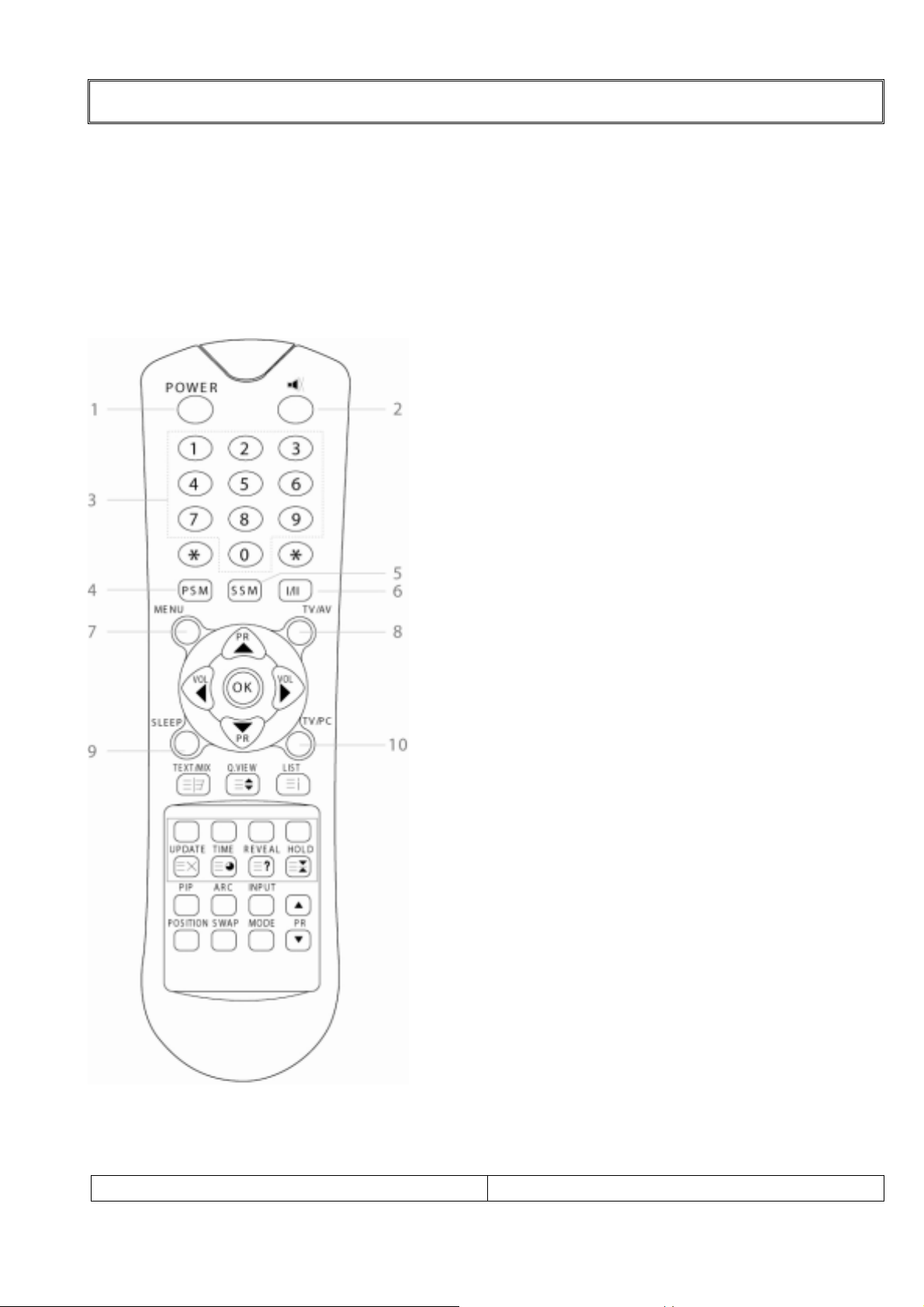
Remote controller
Note !! : Before you use the remote controller, please install the batteries.
1.POWER:
Turns the TV on from standby or off to
standby mode.
2.MUTE:
Turns the sound on and off
3.NUMBER buttons:
Select channel numbers.
4.PSM (Picture Status Memory):
Recalls your preferred picture setting.
5.SSM (Sound Status Memory):
Recalls your preferred sound setting.
6. I / II:
Selects the language during dual
language broadcast. / Selects the
sound output.
7.MENU:
Displays a main menu.
8.TV / AV:
Selects input signal source.
/ Clears the menu from the screen.
9.SLEEP:
Sets the sleep timer.
10.TV / PC :
Selects TV or PC mode directly.
※Note!! Disabled-PDI-P20LCD Does
not support PC mode.
30INCH LCD SERVICE MANUAL
PAGE:
10
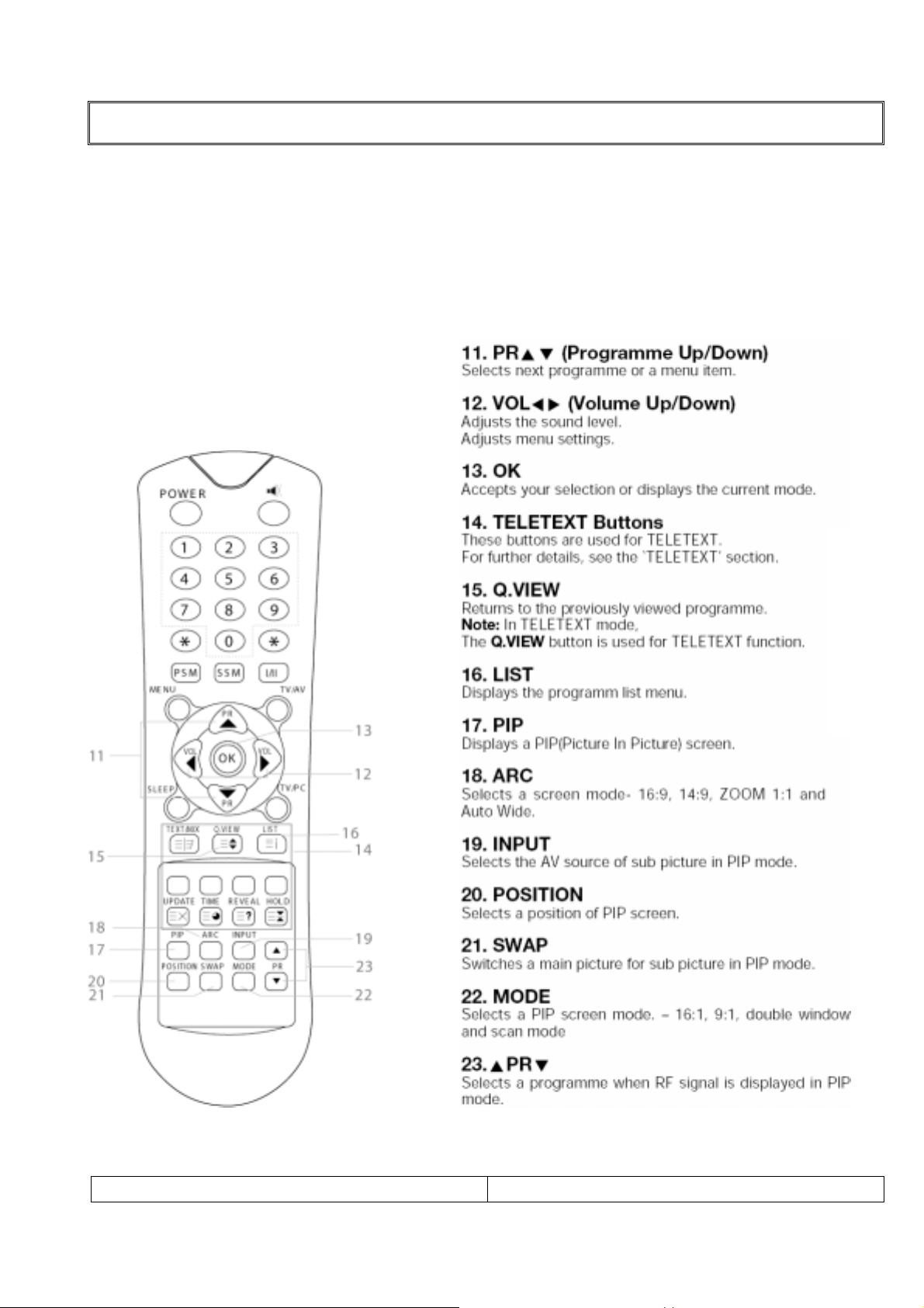
CONTROL DESCRIPTIONS
Remote controller
Note !! : Before you use the remote controller, please install the batteries.
30INCH LCD SERVICE MANUAL
PAGE:
11
◎ ◎
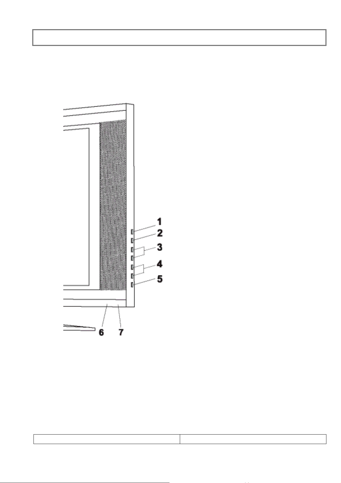
Controller of Panel
< SIDE VIEW>
30INCH LCD SERVICE MANUAL
CONTROL DESCRIPTIONS
1.ON/OFF:
Switches TV set on or off.
2.MENU:
Display a menu.
3.+ PR - ( Programme Up/Down):
Selects a programme or a menu item.
4.+ VOL -( Volume Up/Down):
Adjusts the volume.
Adjusts menu settings.
5.TV/AV:
Selects input signal source.
Clears the menu from the screen.
6:POWER INDICATOR:
Illuminates red when the TV is inpower standby mode.
Illuminates green when the TV isswitched power on mode.
Illuminates amber when the TV isswitched power saving mode.
7.REMOTE CONTROL SENSOR:
Accepts the IR signal of remote
controller.
PAGE:
12

External IN / OUT
EXTERNAL IN/OUT PORTS
30INCH LCD SERVICE MANUAL
PAGE:
13

ADJUSTMENT
1.Safety Precautions
1. Never disconnect leads while the TV receiver is on.
2. Don't short any portion of circuits while power is on.
3. The adjustment must be done by the correct appliances. But this is changeable in view
of productivity.
4. Unless otherwise noted, set the line voltage to 230Vac 10%, 50Hz ./ 110Vac, 60Hz
2.Test Equipment required
1. RF signal generator (with pattern generator)
2. Multi meter (volt meter)
3. Oscilloscope
4. LCD Color analyzer
3.RF AGC (Automatic Gain Control) Adjustment
Note!! Adjust a RF AGC of world standard tuner only.
2 in 1 tuner need not AGC adjust.
The RF AGC was aligned at the time of manufacture for optimum performance over a wide
range conditions. Readjustment of RF AGC should not be necessary unless unusual local
conditions exist, such as ;
1) Channel interference in a CATV system.
2) Picture bending and/or color beats, which are unusually due to excessive RF signal
input when the receiver is too close to a transmitting tower or when the receiver is
connected to an antenna distribution system where the RF signal has been amplified. In
this case, the input signal should be attenuated (with pad or filter) to a satisfactory level.
3) Picture noise caused by "broadcast noise" or weak signal. If the broadcast is "clean"
and the RF signal is at least 1mV (60dBu), the picture will be noise free in any area.
Adjusting RF AGC to one end of rotation will usually cause a relatively poor signal to noise
ratio; Adjusting to the other end of rotation will usually cause a degradation of over load
capabilities resulting in color beats or adjacent channel interference.
Adjustment Note!!
1. Connect RF signal (65dB± 0.5dB) and turn on the TV.
2. Press MENU buttons on TV set and Remote Controller at the same time to get into
SVC mode.
3. Press YELLOW button on the Remote Controller several times to find AGC.
4. Press Volume UP/DOWN button until the AGC Voltage is the same as the Table
below.
5. Press OK button to memorize the data.
6. Press TV/AV button to exit SVC mode.
30INCH LCD SERVICE MANUAL
PAGE:
14
ADJUSTMENT
4.SVC Data Adjustment
NOTE!! When the EEPROM has been replaced, the SVC data should be restored as the
function of individual system and specification.
1) Press 5 Seconds MENU buttons on both TV set and Remote Controller at the same
time to get into SVC mode.
2) Press the Yellow button several times to find SVC Data.
3) Input the corresponding SVC data referring to Table below with the Volume Up/down
key.
4) Press the OK button to memorize the data.
5) Press TV/AV button to exit SVC mode
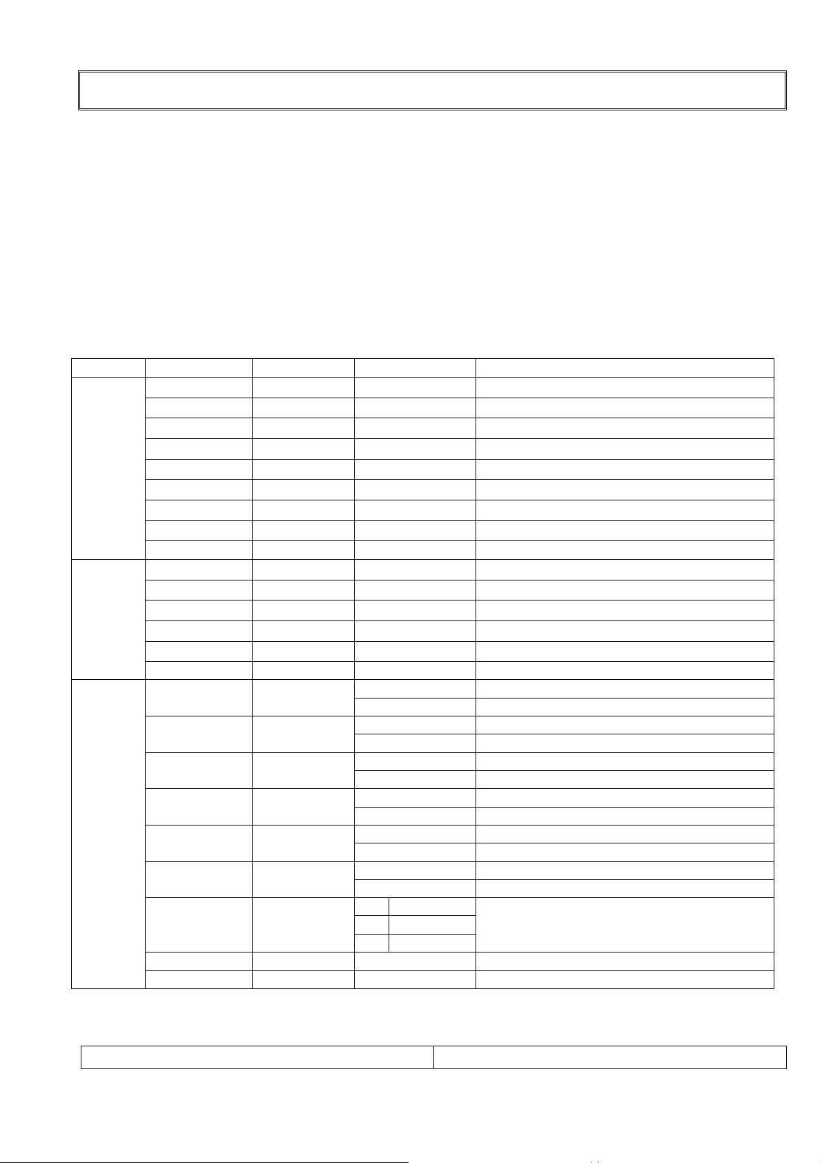
5.SVC Data Table
PAGE ITEM VALUE1 VALUE2
DATA 1
DATA 2
DATA 3
AGC
RD
GD
BD
RO
GO
BO
PC CP
50 PR * * means current program NO.
FP
NP
SP
S1 VOL
S2 VOL
50 PR * * means current program NO.
200PR 0
TEXT 1
TOP 1
SCART 0
ACMS 1
CH+AU 0
SYS 2
50 PR *
106 Opt 1
15
127
127
127
79
79
79
5
21
89
50
105
105
0 BG/I/DK
1 BG/I/DK/L
2 BG/I/DK/M
0 100PR
1 200PR
0 Not apply to TEXT
1 Apply to TEXT
0 TELETEXT TOP OFF
1 TELETEXT TOP ON
0 Apply to COMPONENT
1 Apply to SCART
0 Not apply to ACMS
1 Apply to ACMS
0 Used except for CHINESS or AUSTRALIA
1 Used CHINESS or AUSTRALIA
Variable Data(0-31)
PC Contrast Coefficient-RED(0-255)
PC Contrast Coefficient-GREEN(0-255)
PC Contrast Coefficient-BLUE(0-255)
PC Brightness Coefficient-RED(0-63)
PC Brightness Coefficient-GREEN(0-63)
PC Brightness Coefficient-BLUE(0-63)
PC Charge Pump(0-7)
FM Prescaler(0-127)
NICAM Prescaler(0-127)
SCART Prescaler(0-127)
SCART1 Volume(0-127)
SCART2 Volume(0-127)
SYSTEM OPTION
* means current program NO.
Translate HEX into DEC(DATA3VALUE1)
REMARK
30INCH LCD SERVICE MANUAL
PAGE:
15
ADJUSTMENT
5-1 .SVC Data Table
PAGE ITEM VALUE1 VALUE2
0
1
0 Not apply to MONO option
1 Apply to MONO option
0 Not apply to NICAM STEREO option
1 Apply to NICAM STEREO option
0 Sound curve option 1
1 Sound curve option 2
DATA 4
DUAL 0
MONO 0
A2 ST 1
VOL 1
0 ENG ONLY ENGLISH ONLY
1 EU-5EA
2 EU CIS EU-5EA + CIS
LANG 2
3 E+CHINA ENGLISH + CHINESS
4 E+HUNGARY ENGLISH+ HUNGRAY
5 RESERVED
6 RESERVED
7 RESERVED
0 WEST EU
REMARK
Not apply to DUAL option
Apply to DUAL option
ENGLISH/GERMAN/FRANCE/ITALY/
SPAIN
WEST EU U.K/GERMAN
/FRANCE/ITALY/SPAIN/
SWEDEN/CZECH Rep./
NORWAY etc
DATA 5
1 EAST EU1 POLAND/SLOVENIA/ROMANIA etc
2 TURKEY EU TURKEY
3 EAST EU2 HUNGRY/SERVIA
4 CYRILLIC1 ESTONIA
5 CYRILLIC2 ESTONIA
T-LAN 6
50 PR *
57 Opt 2
FVS 1
DVI 1
D-TV
VCHIP
WOFER 1
6 CYRILLIC3
7 TURK GRE1
8 TURK GRE2
9 TURK GRE3 TURKEY/GREECE
10 ARAB ERA
11 ARAB ENG ARAB CULTURE
12 ARAB HEB1
13 ARAB HEB2 ARAB/HEBREW
14 FARS ENG PARSI
15 FARS FRA
16 FARS ALL
RUSIA/UKRAINE/ESTONIA/CROATI
A/KAZAKHSTAN
* means current program NO.
Translate HEX into DEC(DATA4)
Frequency voltage
Disable/Enable(0-1)
Fix (All Model application)
D-TV Disable/Enable (0-1)
Violence Disable/Enable (0-1)
Fix (All Model application)
30INCH LCD SERVICE MANUAL
PAGE:
16
 Loading...