

Page 1
ZBX-540E Safety Cover
Assembly Instructions
This document provides instructions for service personnel. These procedures should not be
performed by the end user.
————————— Important Notes on Assembly Operations —————————
WARNING
WARNING
➢ Before attempting these operations, read through this manual and familiarize yourself with the installation loca-
tion and orientation of each part.
➢ Assembly operations are to be performed by two or more persons.
➢ To prevent injury, wear gloves when performing these operations.
➢ Be sure to use some means to secure the emplacement base and safety cover.
Supported model
MODELA Pro II MDX-540
External dimensions
W x D x H: 1,042 x 1,030 x 978 mm (41 x 40.6 x 38.5 in.)
Weight
68 kg (150 lb.)
Before attempting these operations, unplug the power cord for the modeling machine. Failure to do so may result in danger of electrical shock, electrocution, or entanglement.
After completing the operations, be sure to verify the operation of the interlock switch,
and never use the machine if the switch does not operate correctly.
1
Page 2
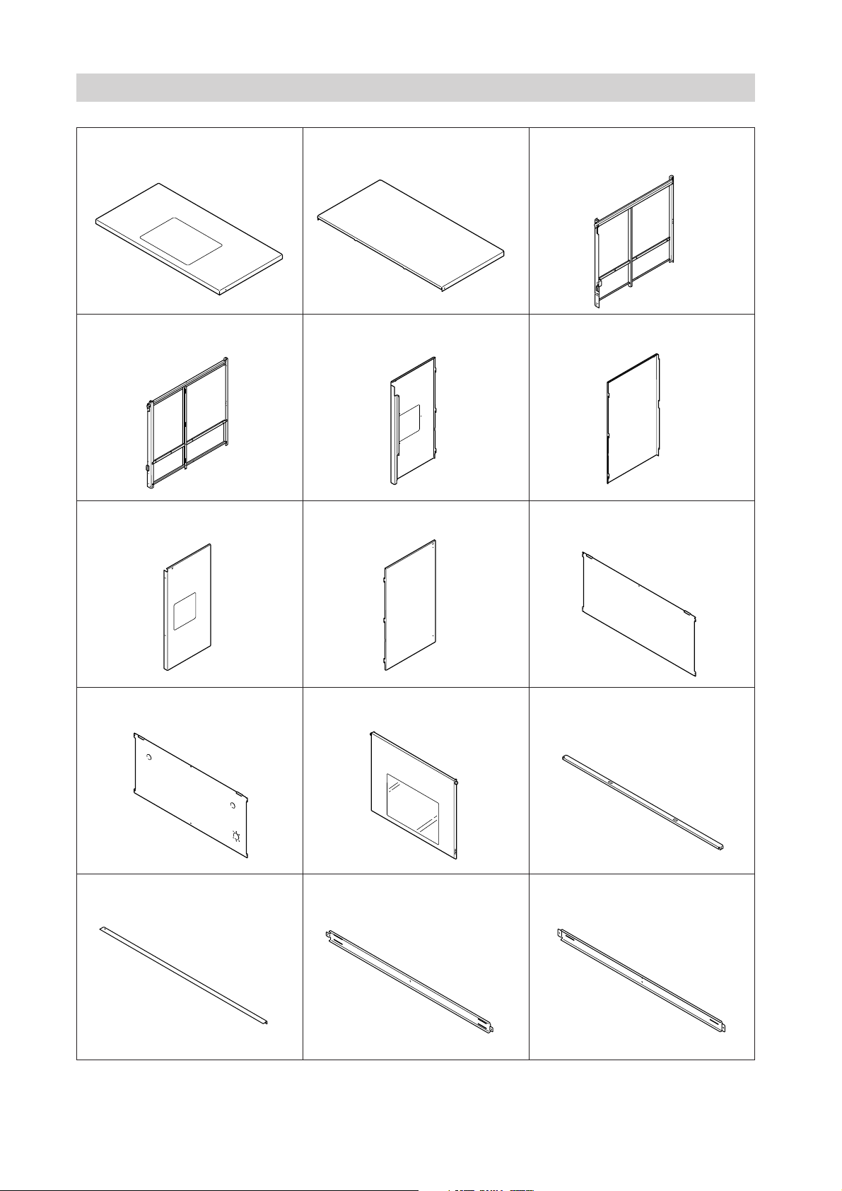
Part List
Top panel A x 1 Top panel B x 1 Left side frame x 1
Right side frame x 1 Left side panel A x 1 Left side panel B x 1
Right side panel A x 1 Back panel A x 1
Back panel B x 1 Hatch panel x 1 Top frame A x 1
Top frame B x 1 Back frame A x 1 Back frame B x 1
Right side panel B x 1
2
Page 3
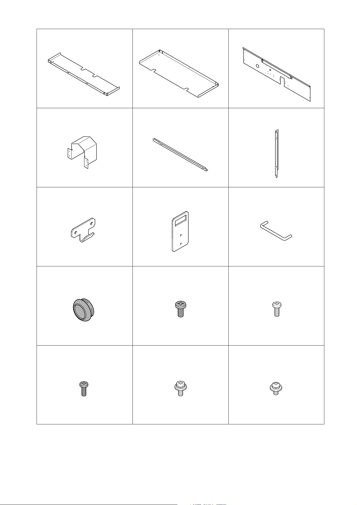
Bottom stay A x 1 Bottom stay B x 1 Front cover x 1
Wiring covers A x 2 Wiring cover B x 1 Wiring cover C x 1
Handy-panel bracket x 1 Handy-panel hanger x 1 Handles x 2
Rubber caps x 3 Screws (M5 x 8 mm) x 4 Screws (silver, M4 x 8 mm) x 52
Screws (black, M4 x 8 mm) x 4 Screws, with washer
(M4 x 8 mm) x 2
Screws, with washer
(M4 x 6 mm) x 2
3
Page 4
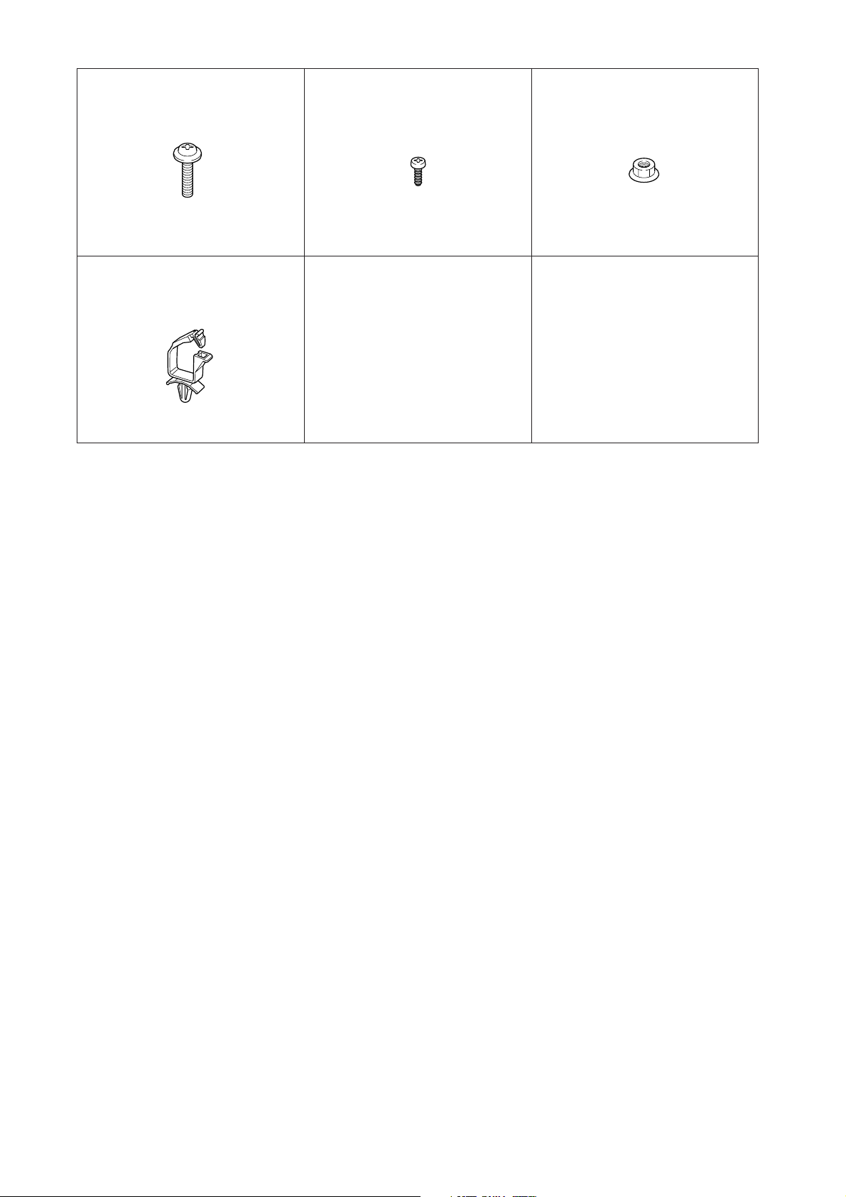
Screws, with flange
(M4 x 14 mm) x 4
Cable retainer x 1
Tapping screws (M3 x 8 mm) x 2 Nuts, with flange (M4 mm) x 2
4
Page 5

Assembly
➊
Switch box
➀ Place the modeling machine at the installation loca-
tion.
➁ Remove the switch box from the modeling machine (4
screws). Pull out the wiring from the switch box.
Note: Place the removed switch box on the modeling
machine's table or base cover.
➋
Bottom stay A
➌
Left side frame
Top flame A
Bottom stay B
➀ Line up bottom stays A and B with the modeling
machine's rubber feet and perform positioning of the
safety cover.
Note: After the safety cover has been installed, the modeling machine cannot be relocated. Be sure to perform
emplacement of the modeling machine before attaching the safety cover.
Back flame A
Back flame B
Back flame
Right side frame
Screws: silver, M4 x 8 mm
➀ Attach the left side frame.
➁ Attach the right side frame.
➂ Attach the top frame A.
➃ Attach the back frames A and B.
Side frame
Top flame A
Side frame
5
Page 6

➍
Screws
M5 x 8 mm
Handle
Hatch panel
➀ Attach the handles to the hatch panel.
➎
Top flame B
Top panelA
Screws
M5 x 8 mm
Handle
Top panel B
Hatch panel
Screws:
➀ Attach the hatch panel. Spread the side frames open
➁ Attach the top frame B.
➂ Attach the top panels A and B.
silver, M4x8mm
slightly and fit the rollers onto the rails.
Roller
Rail
Top panel
Top flameA
6
Page 7

➏
Interlock switch
The interlock wiring is along
in the frame.
➀ Attach the wiring covers B and C.
Wiring cover C
Screws
silver, M4x8mm
Screws, with washer
M4x6mm
Wiring cover B
Note: When installing the wiring covers B and C and
the switch box, be especially careful to keep the interlock wiring from being pinched.
➐
Rubber cap
Screws
silver, M4x8mm
➀ Attach the wiring covers A to the front cover.
➁ Attach the cable retainer.
➂ Attach the rubber cap.
Cable retainer
Front cover
Note: Using a cutter, make a cross-shaped cut in the
center of the rubber cap for the front cover as required.
This cut is used when you want to pass the sensor cable
or the like through.
Wiring covers A
7
Page 8

➑
Cable retainer
Interlock wiring
Screws
black, M4x8mm
Screws
black, M4x8mm
➀ Pass the interlock wiring through the cable retainer and
the hole in the front cover.
➁ Attach the front cover.
➒
Front cover
Interlock wiring
Front cover
Switch box
Dummy connector
➀ Remove the dummy connector from the switch box.
➁ Connect the interlock wiring to the switch box and at-
tach the switch box to the front cover. When doing
this, press in any excess wiring into the switch box.
Press in any excess wiring
into the switch box.
8
Page 9

➓
Hatch panel
Front coverMagnet
Hole
Switch
Push plate
Screws
Hatch panel
Push plate
Adjusting the Interlock Switch
Make sure the push plate is positioned at the center of the
hole for the interlock switch when the hatch panel is
closed. If it is misaligned, then it must be adjusted by loosening the screws for the front cover and tilting the side
frames slightly to the left or right, with the hatch panel
kept closed.
Make sure the interlock switch is pressed down fully when
Left side panel B
Left side panel A
The screws are loosened.
the hatch panel is closed. If the switch is not pressed,
loosen the screws for the push plate and adjust the positioning.
How to Close the Hatch Panel
Lower the hatch panel, lift the handles slightly, and position so that the bottom edge of the hatch panel straddles
the protrusion at the top of the front panel.
Side panel
Side frame
Screws:
➀ Attach the left side panels A and B.
➁ Attach the right side panels A and B.
silver, M4x8mm
Right side panel B
Right side panel A
9
Page 10

Handy-panel bracket
Screws, with washer
M4x8mm
Nuts,
with flange
➀ Attach the handy-panel bracket.
➁ Mount the handy-panel hanger on the handy panel.
Handy-panel
hanger
Tapping screws
M3x8mm
Handy panel
➀ Remove the ventilation-duct filter.
Note: Perform attachment and detachment of the ventilation-duct filter while turning it clockwise. When doing this, grasp the hose at a location a short distance
away from its end.
Hose
Ventilation-duct filter
10
Page 11

➀ Attach the back panel B.
Back flame B
Back panel B
Back panel B
Screws
silver, M4x8mm
Screws, with flange
M4x14mm
Hose
➀ Connect the ventilation-duct filter to the hose and at-
tach it to the back panel B.
Back panel B
Ventilation-duct filter
Note: Perform attachment and detachment of the ventilation-duct filter while turning it clockwise. When doing this, grasp the hose at a location a short distance
away from its end.
Note: Insert the hose securely, as far as it will go. If it is
difficult to insert, apply a small amount of water or alcohol to the inside of the hose.
11
Page 12

Rubber cap
Rubber cap
➀ Attach the rubber caps.
➁ Pass the power cord and other necessary cables through
the rubber caps and connect them to the modeling
machine.
Note: Use a cutter to make a cross-shaped cut in the
centers of the rubber caps to match the thickness of
the cables.
Back flame A
Back panel A
Screws
silver, M4 x 8 mm
Back panel A
➀ Attach the back panel A.
➀ Make sure the hatch panel opens and closes
➁ Close the hatch panel and start the modeling
➂ Make sure that the interlock feature is actu-
12
smoothly.
machine. Make sure that cutting operation is
possible when the hatch panel is closed.
ated and cutting operation is restricted when
the hatch panel is opened.
Note: If the interlock feature is not actuated correctly,
repeat the adjustment in step 10.
DOC-0596 R1-060621
 Loading...