

Page 1
OWNER’S MANUAL
Thank you, and congratulations on your choice of the Roland XV-5080.
Before using this unit, carefully read the sections entitled: “IMPORTANT SAFETY INSTRUC
TIONS” (p. 2), “USING THE UNIT SAFELY” (p. 3), and “IMPORTANT NOTES” (p. 5). These
sections provide important information concerning the proper operation of the unit. Additionally, in order to feel assured that you have gained a good grasp of every feature provided
by your new unit, Owner’s Manual and Quick Start should be read in its entirety. The manual
should be saved and kept on hand as a convenient reference.
Notation Used in This Owner’s Manual
To make operation procedures easy to understand, the following notation system is
adopted:
Characters and numbers in square brackets [ ] indicate buttons on the front panel. For
example, [PATCH] represents the PATCH button and [ENTER] the ENTER button.
-
An asterisk (*) at the beginning of a paragraph indicates a note or precaution.
(p. **) refers to pages within the manual.
* The display screens printed in this owner’s manual are based on the factory settings.
However, please be aware that in some cases they may differ from the actual factory settings.
*
Microsoft and MS-DOS are registered trademarks of Microsoft Corporation.
*
Microsoft, Windows, and Windows NT are registered trademarks of Microsoft Corporation.
Windows® 3.1 is known officially as: “Microsoft® Windows® operating system Version 3.1.”
*
*
Windows® 95 is known officially as: “Microsoft® Windows® 95 operating system.”
* Windows® 98 is known officially as: “Microsoft® Windows® 98 operating system.”
* MacOS is a trademark of Apple Computer, Inc.
* Zip is a trademark of Iomega Corporation.
* SmartMedia is a trademark of Toshiba Corporation.
* All product names mentioned in this document are trademarks or registered trademarks of their
respective owners.
Copyright © 2000 ROLAND CORPORATION
All rights reserved. No part of this publication may be reproduced in any form without the
written permission of ROLAND CORPORATION.
Page 2
CAUTION
RISK OF ELECTRIC SHOCK
DO NOT OPEN
ATTENTION: RISQUE DE CHOC ELECTRIQUE NE PAS OUVRIR
CAUTION: TO REDUCE THE RISK OF ELECTRIC SHOCK,
DO NOT REMOVE COVER (OR BACK).
NO USER-SERVICEABLE PARTS INSIDE.
REFER SERVICING TO QUALIFIED SERVICE PERSONNEL.
The lightning flash with arrowhead symbol, within an
equilateral triangle, is intended to alert the user to the
presence of uninsulated “dangerous voltage” within the
product’s enclosure that may be of sufficient magnitude to
constitute a risk of electric shock to persons.
The exclamation point within an equilateral triangle is
intended to alert the user to the presence of important
operating and maintenance (servicing) instructions in the
literature accompanying the product.
INSTRUCTIONS PERTAINING TO A RISK OF FIRE, ELECTRIC SHOCK, OR INJURY TO PERSONS.
IMPORTANT SAFETY INSTRUCTIONS
SAVE THESE INSTRUCTIONS
WARNING - When using electric products, basic precautions should always be followed, including the following:
1. Read these instructions.
2. Keep these instructions.
3. Heed all warnings.
4. Follow all instructions.
5. Do not use this apparatus near water.
6. Clean only with a damp cloth.
7. Do not block any of the ventilation openings. Install in
accordance with the manufacturers instructions.
8. Do not install near any heat sources such as radiators,
heat registers, stoves, or other apparatus (including
amplifiers) that produce heat.
9. Do not defeat the safety purpose of the polarized or
grounding-type plug. A polarized plug has two blades with
one wider than the other. A grounding type plug has two
blades and a third grounding prong. The wide blade or the
third prong are provided for your safety. When the provided
plug does not fit into your outlet, consult an electrician for
replacement of the obsolete outlet.
WARNING:
IMPORTANT:
As the colours of the wires in the mains lead of this apparatus may not correspond with the coloured markings identifying
the terminals in your plug, proceed as follows:
The wire which is coloured GREEN-AND-YELLOW must be connected to the terminal in the plug which is marked by the
letter E or by the safety earth symbol or coloured GREEN or GREEN-AND-YELLOW.
The wire which is coloured BLUE must be connected to the terminal which is marked with the letter N or coloured BLACK.
The wire which is coloured BROWN must be connected to the terminal which is marked with the letter L or coloured RED.
THIS APPARATUS MUST BE EARTHED
THE WIRES IN THIS MAINS LEAD ARE COLOURED IN ACCORDANCE WITH THE FOLLOWING CODE.
GREEN-AND-YELLOW: EARTH, BLUE: NEUTRAL, BROWN: LIVE
10. Protect the power cord from being walked on or pinched
particularly at plugs, convenience receptacles, and the
point where they exit from the apparatus.
11. Only use attachments/accessories specified by the
manufacturer.
12. Never use with a cart, stand, tripod, bracket,
or table except as specified by the
manufacturer, or sold with the apparatus.
When a cart is used, use caution when
moving the cart/apparatus combination to
avoid injury from tip-over.
13. Unplug this apparatus during lightning storms or when
unused for long periods of time.
14. Refer all servicing to qualified service personnel. Servicing
is required when the apparatus has been damaged in any
way, such as power-supply cord or plug is damaged, liquid
has been spilled or objects have fallen into the apparatus,
the apparatus has been exposed to rain or moisture, does
not operate normally, or has been dropped.
For the U.K.
2
Page 3
USING THE UNIT SAFELY
Used for instructions intended to alert
the user to the risk of death or severe
injury should the unit be used
improperly.
Used for instructions intended to alert
the user to the risk of injury or material
damage should the unit be used
improperly.
* Material damage refers to damage or
other adverse effects caused with
respect to the home and all its
furnishings, as well to domestic
animals or pets.
• Before using this unit, make sure to read the
instructions below, and the Owner’s Manual.
..........................................................................................................
• Do not open or perform any internal modifications on the unit. (The only exception would be
where this manual provides specific instructions
which should be followed in order to put in place
user-installable options; see QuickStart (p. 3, p.
34), Reference Manual (p. 181).)
..........................................................................................................
• Do not attempt to repair the unit, or replace parts
within it (except when this manual provides
specific instructions directing you to do so). Refer
all servicing to your retailer, the nearest Roland
Service Center, or an authorized Roland
distributor, as listed on the "Information" page.
..........................................................................................................
• Never use or store the unit in places that are:
• Subject to temperature extremes (e.g., direct
sunlight in an enclosed vehicle, near a heating
duct, on top of heat-generating equipment); or
are
• Damp (e.g., baths, washrooms, on wet floors);
or are
• Humid; or are
• Exposed to rain; or are
• Dusty; or are
• Subject to high levels of vibration.
..........................................................................................................
• This unit should be used only with a rack or stand
that is recommended by Roland.
..........................................................................................................
• When using the unit with a rack or stand recommended by Roland, the rack or stand must be
carefully placed so it is level and sure to remain
stable. If not using a rack or stand, you still need
to make sure that any location you choose for
placing the unit provides a level surface that will
properly support the unit, and keep it from
wobbling.
..........................................................................................................
The symbol alerts the user to important instructions
or warnings.The specific meaning of the symbol is
determined by the design contained within the
triangle. In the case of the symbol at left, it is used for
general cautions, warnings, or alerts to danger.
The symbol alerts the user to items that must never
be carried out (are forbidden). The specific thing that
must not be done is indicated by the design contained
within the circle. In the case of the symbol at left, it
means that the unit must never be disassembled.
The ● symbol alerts the user to things that must be
carried out. The specific thing that must be done is
indicated by the design contained within the circle. In
the case of the symbol at left, it means that the powercord plug must be unplugged from the outlet.
• The unit should be connected to a power supply
only of the type described in the operating instructions, or as marked on the unit.
..........................................................................................................
• Do not excessively twist or bend the power cord,
nor place heavy objects on it. Doing so can
damage the cord, producing severed elements and
short circuits. Damaged cords are fire and shock
hazards!
..........................................................................................................
• This unit, either alone or in combination with an
amplifier and headphones or speakers, may be
capable of producing sound levels that could
cause permanent hearing loss. Do not operate for
a long period of time at a high volume level, or at
a level that is uncomfortable. If you experience
any hearing loss or ringing in the ears, you should
immediately stop using the unit, and consult an
audiologist.
..........................................................................................................
• Do not allow any objects (e.g., flammable material,
coins, pins); or liquids of any kind (water, soft
drinks, etc.) to penetrate the unit.
..........................................................................................................
• In households with small children, an adult
should provide supervision until the child is
capable of following all the rules essential for the
safe operation of the unit.
..........................................................................................................
• Protect the unit from strong impact.
(Do not drop it!)
..........................................................................................................
3
Page 4
• Do not force the unit’s power-supply cord to share
an outlet with an unreasonable number of other
devices. Be especially careful when using
extension cords—the total power used by all
devices you have connected to the extension
cord’s outlet must never exceed the power rating
(watts/amperes) for the extension cord. Excessive
loads can cause the insulation on the cord to heat
up and eventually melt through.
..........................................................................................................
• Before using the unit in a foreign country, consult
with your retailer, the nearest Roland Service
Center, or an authorized Roland distributor, as
listed on the "Information" page.
..........................................................................................................
• Always turn the unit off and unplug the power
cord (QuickStart p. 8) before attempting installation of the circuit board (SRX series, SR-JV80
series ; QuickStart p. 3).
• The unit should be located so that its location or
position does not interfere with its proper ventilation.
..........................................................................................................
• Always grasp only the plug on the power-supply
cord when plugging into, or unplugging from, an
outlet or this unit.
..........................................................................................................
• Try to prevent cords and cables from becoming
entangled. Also, all cords and cables should be
placed so they are out of the reach of children.
..........................................................................................................
• Never climb on top of, nor place heavy objects on
the unit.
..........................................................................................................
• Never handle the power cord or its plugs with wet
hands when plugging into, or unplugging from,
an outlet or this unit.
..........................................................................................................
• Before moving the unit, disconnect the power
plug from the outlet, and pull out all cords from
external devices.
..........................................................................................................
• Before cleaning the unit, turn off the power and
unplug the power cord from the outlet (QuickStart
p. 12).
..........................................................................................................
• Whenever you suspect the possibility of lightning
in your area, pull the plug on the power cord out
of the outlet.
..........................................................................................................
• Install only the specified circuit board(s) (SRX
series, SR-JV80 series). Remove only the specified
screws (Quick Start p. 4).
..........................................................................................................
• Should you remove the optical connector caps,
make sure to put them in a safe place out of
children's reach, so there is no chance of them
being swallowed accidentally.
..........................................................................................................
4
Page 5
IMPORTANT NOTES
In addition to the items listed under “IMPORTANT SAFETY INSTRUCTIONS” and “USING THE UNIT SAFELY” on pages 2
and 3, please read and observe the following:
Power Supply
• Do not use this unit on the same power circuit with any
device that will generate line noise (such as an electric
motor or variable lighting system).
• Before connecting this unit to other devices, turn off the
power to all units. This will help prevent malfunctions
and/or damage to speakers or other devices.
Placement
• This device may interfere with radio and television
reception. Do not use this device in the vicinity of such
receivers.
• Do not expose the unit to direct sunlight, place it near
devices that radiate heat, leave it inside an enclosed
vehicle, or otherwise subject it to temperature extremes.
Excessive heat can deform or discolor the unit.
• To avoid possible breakdown, do not use the unit in a wet
area, such as an area exposed to rain or other moisture.
Maintenance
• For everyday cleaning wipe the unit with a soft, dry cloth
or one that has been slightly dampened with water. To
remove stubborn dirt, use a cloth impregnated with a
mild, non-abrasive detergent. Afterwards, be sure to wipe
the unit thoroughly with a soft, dry cloth.
• Never use benzine, thinners, alcohol or solvents of any
kind, to avoid the possibility of discoloration and/or
deformation.
Repairs and Data
• Please be aware that all data contained in the unit’s
memory may be lost when the unit is sent for repairs.
Important data should always be backed up Memory
Card, or written down on paper (when possible). During
repairs, due care is taken to avoid the loss of data.
However, in certain cases (such as when circuitry related
to memory itself is out of order), we regret that it may not
be possible to restore the data, and Roland assumes no
liability concerning such loss of data.
Additional Precautions
• Please be aware that the contents of memory can be
irretrievably lost as a result of a malfunction, or the
improper operation of the unit. To protect yourself against
the risk of loosing important data, we recommend that
you periodically save a backup copy of important data
you have stored in the unit’s memory, a memory card.
• Unfortunately, it may be impossible to restore the contents
of data that was stored in the unit’s memory, a memory
card, or another MIDI device (e.g., a sequencer) once it has
been lost. Roland Corporation assumes no liability
concerning such loss of data.
• Use a reasonable amount of care when using the unit’s
buttons, sliders, or other controls; and when using its jacks
and connectors. Rough handling can lead to malfunctions.
• Never strike or apply strong pressure to the display.
• When connecting / disconnecting all cables, grasp the
connector itself—never pull on the cable. This way you
will avoid causing shorts, or damage to the cable’s
internal elements.
• A small amount of heat will radiate from the unit during
normal operation.
• To avoid disturbing your neighbors, try to keep the unit’s
volume at reasonable levels. You may prefer to use
headphones, so you do not need to be concerned about
those around you (especially when it is late at night).
• When you need to transport the unit, package it in the box
(including padding) that it came in, if possible. Otherwise,
you will need to use equivalent packaging materials.
• The display screens printed in this owner’s manual are based
on the factory settings. However, please be aware that in
some cases they may differ from the actual factory settings.
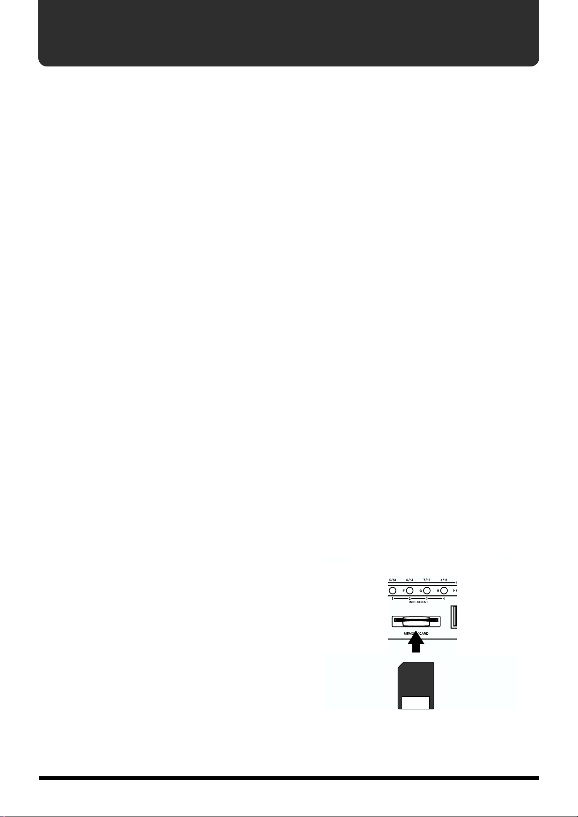
Before Using Cards
Using DATA Cards
• Carefully insert the DATA card all the way in—until it is
firmly in place.
Memory Backup
• This unit contains a battery which powers the unit’s
memory circuits while the main power is off. When this
battery becomes weak, the message shown below will
appear in the display. Once you see this message, have the
battery replaced with a fresh one as soon as possible to
avoid the loss of all data in memory. To have the battery
replaced, consult with your retailer, the nearest Roland
Service Center, or an authorized Roland distributor, as
listed on the “Information” page.
“Battery Low”
• Insert memory cards with the gold contacts facing
downwards.
• Never touch the terminals of the DATA card. Also, avoid
getting the terminals dirty.
5
Page 6

Contents
USING THE UNIT SAFELY......................................................................3
IMPORTANT NOTES ...............................................................................5
Features.................................................................................................11
Panel Descriptions................................................................................12
Front Panel.................................................................................................................................................12
Rear Panel.................................................................................................................................................. 14
Chapter 1 Selecting and Playing a Sound..........................................16
Auditioning Sounds on the XV-5080 (Phrase Preview)......................................................................16
Setting the Way In Which Sounds Are Previewed...................................................................16
Playing a Patch on the XV-5080 from External MIDI Devices (MIDI Keyboard)...........................17
Setting the XV-5080’s MIDI Reception Channels.....................................................................17
Selecting a Mode (Patch, Performance, or Rhythm Set) ..................................................................... 17
Selecting Sound Libraries........................................................................................................................18
Selecting a Patch ....................................................................................................................................... 19
Basic Procedure for Selecting a Patch.........................................................................................19
Selecting Patches by Category (Patch Finder) ..........................................................................19
Selecting Patches and Rhythm Sets from an External MIDI Device...................................... 21
Setting a Patch’s Pitch in Octave Steps (Octave Shift) ........................................................................23
Selecting How a Patch Will Play (Polyphonic/Monophonic)...........................................................23
Chapter 2 Using the XV-5080 Effects..................................................24
Turning Effects On/Off........................................................................................................................... 24
Patch Mode Settings.................................................................................................................................24
Routing Tones to Effects ..............................................................................................................25
Making Multi-Effects Settings.....................................................................................................26
Making Chorus Settings...............................................................................................................26
Making Reverb Settings ............................................................................................................... 28
Performance Mode Settings.................................................................................................................... 30
Routing Part Outputs ................................................................................................................... 31
Making Multi-Effects Settings.....................................................................................................31
Making Chorus Settings...............................................................................................................32
Making Reverb Settings ............................................................................................................... 34
Rhythm Set Mode Settings......................................................................................................................36
Routing Tones to Effects ..............................................................................................................37
Making Multi-Effects Settings.....................................................................................................37
Making Chorus Settings...............................................................................................................38
Making Reverb Settings ............................................................................................................... 39
Settings in General MIDI Mode..............................................................................................................41
Parameters for Each Multi-Effects .........................................................................................................41
Copying Effect Settings .........................................................................................................................106
Chapter 3 Selecting Output Jacks.....................................................107
Patch Mode Settings...............................................................................................................................107
Signal (TONE) Flow.................................................................................................................... 107
Parameters.................................................................................................................................... 108
Example of Settings.....................................................................................................................110
Performance Mode Settings.................................................................................................................. 111
Signal (PART) Flow ....................................................................................................................111
Parameters.................................................................................................................................... 111
Example of Settings.....................................................................................................................113
Rhythm Set Mode Settings....................................................................................................................114
Signal (RHYTHM TONE) Flow ................................................................................................114
Parameters.................................................................................................................................... 114
Settings in General MIDI Mode............................................................................................................117
6
Page 7

Signal (PART) Flow ....................................................................................................................117
Parameters.................................................................................................................................... 117
Digital Connections Using R-BUS........................................................................................................ 119
Settings for the Digital Interface ([SYSTEM/UTILITY] - [F2 (Output)]) ............................ 119
Eight-Channel R-BUS Digital Connection...............................................................................120
Converting to the Various Digital Formats ........................................................................................ 121
Digital Output to an ADAT....................................................................................................... 121
Digital Output to a TASCAM DA Series................................................................................. 122
Digital Output to an AES/EBU Device....................................................................................123
Synchronizing the XV-5080 to the Word Clock arriving at WORD CLOCK IN........................... 124
Chapter 4 Creating Patches...............................................................125
Types of Patches and Their Composition...........................................................................................125
Four-Tone Patch..........................................................................................................................125
How a Tone Is Organized.......................................................................................................... 125
Multi-partial Patch...................................................................................................................... 126
How a Partial Is Organized ....................................................................................................... 126
Selecting the Tones That Will Sound (Tone On/Off)........................................................................ 126
Settings Common to the Entire Patch.................................................................................................. 127
Common (Patch Common)........................................................................................................ 127
Control (Patch Control).............................................................................................................. 129
Structure (Patch Structure) ........................................................................................................ 131
K. Range (Patch Key Range)......................................................................................................132
V. Range (Patch Velocity Range) .............................................................................................. 133
Creating Four-Tone Patches..................................................................................................................134
Tips for Creating a Patch............................................................................................................ 134
More Advanced Editing of Tones............................................................................................. 134
Tips for Selecting a Waveform..................................................................................................135
Modifying the Waveform and Pitch ([F2] (WG)) ...................................................................136
Using the Filter to Modify the Brightness ([F3 (TVF)])..........................................................140
Changing the Volume and Stereo Location ([F4 (TVA)])...................................................... 143
Applying Vibrato or Tremolo ([F5 (LFO&CTL)])................................................................... 145
Creating Multi-Partial Patches ............................................................................................................. 148
Assigning Partials ....................................................................................................................... 148
Editing Partials............................................................................................................................149
Editing Samples........................................................................................................................... 150
Using the Filter to Modify the Brightness ([F3 (TVF)])..........................................................152
Making the Volume Change ([F4 (TVA)])............................................................................... 155
Applying Vibrato or Tremolo ([F5 (LFO&CTL)])................................................................... 156
Making Effect Settings...........................................................................................................................158
Saving Patches You Create.................................................................................................................... 158
Copying the Settings of Another Patch (Patch Tone Copy)............................................................. 158
Chapter 5 Creating a Performance....................................................159
How a Performance Is Organized........................................................................................................ 159
Basic Ways to Use Performances .........................................................................................................159
Choosing the Parts to Play....................................................................................................................159
Establishing Settings for an Entire Performance (COMMON)........................................................160
Settings for Each Part............................................................................................................................. 160
Comparing the Settings of Each Part as You Make Settings.................................................161
Setting the Keyboard Range......................................................................................................161
Selecting the Patch, and Setting the Volume, Pan, Pitch, and Polyphony.......................... 162
Editing the Attack and Release of the Sound and Changing the Way the Sound is Played..
163
Establishing a Part’s MIDI Settings..........................................................................................164
Confirming MIDI Information for Each MIDI Channel........................................................ 166
Making Effect Settings...........................................................................................................................166
Saving Performances You Create.........................................................................................................166
Copying the Settings of Another Part (Performance Part Copy) .................................................... 166
7
Page 8

Editing a Patch or Rhythm Set in the Performance Mode................................................................ 167
Palette Function...........................................................................................................................167
Chapter 6 Creating Rhythm Sets.......................................................168
How Percussion Instruments Are Organized....................................................................................168
Using a MIDI Keyboard to Select a Percussion Instrument for Editing......................................... 168
Settings Common to an Entire Rhythm Set........................................................................................ 169
Setting up Individual Rhythm Tones..................................................................................................170
Tips for Selecting a Waveform..................................................................................................170
Modifying the Waveform, Pan and Pitch ([F2 (Key WG)])................................................... 171
Tune...............................................................................................................................................172
FXM............................................................................................................................................... 172
Using the Filter to Modify the Brightness ([F3 (Key TVF)])..................................................175
Making the Volume Change ([F4 (Key TVA)])....................................................................... 177
Other Settings ([F5 (Key Ctl)])................................................................................................... 179
Making Effect Settings...........................................................................................................................179
Saving the Rhythm Set You Create......................................................................................................179
Copying Settings from Some Other Rhythm Tone............................................................................ 180
Chapter 7 Loading a Variety of Data .................................................181
Loading Sampler Libraries (CD-ROM)...............................................................................................181
Installing the SIMM (Memory Module)...................................................................................181
Cautions When Installing SIMM ..............................................................................................181
Removing SIMMs........................................................................................................................ 182
Installation de la carte d'extension Wave (French language for Canadian Safety Standard).. 183
Connecting a CD-ROM Drive ................................................................................................... 185
With Sampler Libraries .............................................................................................................. 185
About Each Sampler Library Folder Type (Display)............................................................. 187
About the Display of Folder Categories in Sampler Libraries ............................................. 188
Sample Load ................................................................................................................................188
Auto Load.....................................................................................................................................189
Playing Back Loaded Sampler Libraries.............................................................................................190
Loading Data Saved on a Zip Disk......................................................................................................190
Individually Loading Patches, Performances, or Rhythm Sets............................................190
Loading Data Stored on Memory Cards............................................................................................. 191
Sample-Related Utilities........................................................................................................................191
Sending and Receiving Samples (Sample Dump)..................................................................191
Emphasizing and Suppressing the High End of Loaded Samples (Emphasis).................192
Automatically Creating Multi-Partial Patches (Create Patch).............................................. 193
Chapter 8 Saving Tones and Other Data You’ve Created...............194
Saving Edits to the XV-5080’s Internal Memory (Write) .................................................................. 194
When Changing the Settings for the Patch or Rhythm Set Assigned to
a Part in a Performance .............................................................................................................. 195
Saving All Data to Memory Card ([DISK] - [F2 (SAVE)]) ................................................................ 195
Formatting a Memory Card....................................................................................................... 196
Saving Data..................................................................................................................................196
Organizing the Contents of Memory Cards............................................................................ 197
Saving All Data to Zip Disk ([DISK] - [F2 (SAVE)]).......................................................................... 200
Formatting a Zip Disk/Hard Disk (Format)........................................................................... 200
Saving Data..................................................................................................................................200
Organizing a Zip Disk................................................................................................................ 201
Initializing a Sound................................................................................................................................202
For Patches or Performances.....................................................................................................202
For Rhythm Sets..........................................................................................................................202
Changing the Way MIDI Signals Arriving at MIDI IN 2 Are Handled.............................. 203
Transmitting Data to an External MIDI Device (Data Transfer) ..................................................... 203
Transmitting to an External MIDI Device ............................................................................... 203
Destination...................................................................................................................................204
8
Page 9

Transmitting to User Memory...................................................................................................204
Protecting the Internal Memory (Protect)...........................................................................................205
Resetting All Settings to Default Factory Settings (Factory)............................................................ 206
Registering Favorite Patches in the FAVORITE LIST....................................................................... 207
Selecting Patches from the FAVORITE LIST......................................................................................207
Chapter 9 Other Settings/Status Checks..........................................208
Settings Common to the Entire XV-5080 ([SYSTEM/UTILITY] - [F1 (General)])......................... 208
Making Overall Settings............................................................................................................. 208
Setting the Tuning and Volume Settings................................................................................. 209
Setting the System Tempo .........................................................................................................209
Making Scale Tune Settings ([SYSTEM/UTILITY] - [F1 (General)])..............................................209
Making the Equalizer Settings ([SYSTEM/UTILITY] - [F2 (Outp&EQ)] - [F2 (EQ)]) .................. 211
Establishing the MIDI Settings ([SYSTEM/UTILITY] - [F3 (MIDI)])..............................................211
Setting the MIDI Channel .......................................................................................................... 212
Setting the MIDI Transmit/Receive Switch............................................................................ 212
Making the System Exclusive Settings..................................................................................... 212
Specifying the Reception Status for Each Tone ......................................................................212
MIDI IN connectors .................................................................................................................... 213
Connecting Two or More XV-5080s to Increase Polyphony................................................. 214
Selecting Common Controllers ([SYSTEM/UTILITY] - [F4 (Control)])......................................... 215
Confirming the Current Status ([SYSTEM/UTILITY] - [F6 (Info)])................................................215
Chapter 10 Examples of Applications Using the XV-5080 ..............217
Controlling the XV-5080 in Real Time Using an External MIDI Device ........................................217
Changing the Multi-Effects Settings From an External MIDI Device ................................. 217
Modifying Tone Settings............................................................................................................218
Applications for Patches........................................................................................................................ 219
Syncing the LFO Cycle to System Tempo ...............................................................................219
Modifying Multi-Effects to Match the System’s Tempo........................................................219
Making a Tone’s Delay Time Match the System Tempo....................................................... 220
Using a Pedal Switch to Modify the Rotary Speed of the Rotary Effect.............................220
Playing Phrase Loops at a System’s Tempo............................................................................220
Changing the Part Settings from an External MIDI Device.............................................................221
Applications for Matrix Control........................................................................................................... 223
Controlling the TMT with the LFO and Changing the Tone’s Cycle Time Plays..............223
Using the XV-5080 as a General MIDI Sound Module .....................................................................224
Entering GM Mode.....................................................................................................................224
Turning Effects On/Off.............................................................................................................. 225
Modifying GM Mode Settings...................................................................................................225
Utility Functions in GM Mode..................................................................................................228
Protecting the Internal Memory (PROTECT)..................................................................................... 229
Troubleshooting..................................................................................232
No sound ................................................................................................................................................. 232
Can’t select Performances ..................................................................................................................... 232
Can’t select the Part for which to make settings................................................................................ 232
Pitch is wrong .........................................................................................................................................232
Effects do not apply................................................................................................................................233
MIDI messages are not received correctly.......................................................................................... 233
Memory Card cannot be used .............................................................................................................. 233
Song data does not playback correctly................................................................................................233
The SCSI device is not being recognized. ........................................................................................... 233
Error Messages...................................................................................235
About SCSI ..........................................................................................239
Connecting a SCSI device...................................................................................................................... 239
9
Page 10

SCSI Devices That Can Be Used................................................................................................ 239
What you need to know before making connections........................................................................ 239
Types of SCSI cables and SCSI connectors.............................................................................. 239
About SCSI Chains...................................................................................................................... 239
About Terminators...................................................................................................................... 239
About SCSI ID Numbers............................................................................................................240
Making Connections...................................................................................................................240
Parameter List.....................................................................................241
Patch Parameters.........................................................................................................................241
Performance Parameters............................................................................................................249
Rhythm Set Parameters.............................................................................................................. 252
GM Mode Parameters.................................................................................................................255
MFX Prameters............................................................................................................................ 257
System Parameters......................................................................................................................276
Waveform List .....................................................................................277
MIDI Implementation...........................................................................282
Specifications......................................................................................306
10
Page 11
Features
128-Voice Polyphony and 32Part Multitimbrality
The XV-5080 is a 32-part multitimbral sound generator that
produces up to 128 simultaneous polyphonic voices. It provides
ample polyphony, even with Patches containing multiple Tones.
Create Amazingly Expressive Tones
With Patches containing four stereo Tones, as well as four-Tone
instruments in Rhythm Sets—you can use up to a total of eight
wave types—the XV-5080 takes you the next step beyond
Roland’s previous generation of JV-Series modules, providing
even more precise control and allowing you to create lusher,
more expressive sounds.
Powerful Internal Effects, Including COSM Effects
The internal effects have been completely rethought and
improved. The reverb, the XV-5080’s most central effect,
incorporates the high-quality SRV-3030 DSP, allowing the
instrument itself to give great spatial definition with superior,
clear sound.
In addition, the XV-5080 features Multi-effects (MFX) with 90
kinds of effects, including RSS and 3D Delay, Slicer, and
Formant Filter. What’s more, the XV-5080 also features a variety
of combinations of different effects, such as the Guitar Amp
Simulator, made possible with COSM technology; Guitar Multi,
which lets you get just the right guitar, bass, and keyboard
sounds; Bass Multi, and Keyboard Multi, all of which let you
create even more powerful sounds. Furthermore, you can use
three different MFX systems when in Performance mode, and
use each MFX on any Part you select.
On top of all this, each output is supplied with two-band EQ.
Sample Playback Function Lets You Add Waves
By expanding with SIMM (72-pin, 64/32/16 MB) memory
modules, you can add the sample playback function to the XV-
5080. With a CD-ROM drive connected to the SCSI connector,
you can then load Roland’s S-700 Series and other CD-ROM
libraries. You of course can perform using existing sampled
tones just as they are, but you can also synthesize internal
Patches into a single Wave. Additionally, since you can also save
the wave data of loaded samples to SmartMedia cards, you can
easily take pre-existing samples for use in your live
performances, even with no CD-ROM drives or hard disks
connected.
Digital Out and R-BUS for Complete Compatibility with Digital Systems
The XV-5080’s output systems not only include eight parallel
analog outs that can also be used as four stereo pairs, but also S/
P DIF digital outputs (optical and coaxial) and R-BUS digital out
as well. Using R-BUS lets you simply output eight analog
outputs as eight-channel digital audio. And you can connect the
XV-5080 to Roland’s VM-3100Pro or VM-7000 Series with just
one cable.
Furthermore, the XV-5080 includes a Word Clock In as a
standard feature.
Supports General MIDI system Level 2
The XV-5080 provides a mode compatible with General MIDI
System Level 2, the standard format for desktop music (DTM)
systems. The upwardly compatible General MIDI 2 standards
pick up where the original General MIDI standard left off,
offering enhanced expressive capabilities and even greater
compatibility. You can play back commercially available General
MIDI-compatible song data.
Greater Expansion Possibilities with the New-Format Wave Expansion Boards
The XV-5080 accepts up to four of Roland’s new-format Wave
Expansion Boards (SRX Series). In addition, you can add four
previous-generation Wave Expansion Boards (SR-JV Series).
All of this provides you unprecedented power in creating
sounds from a massive amount of waveform data.
Featuring the Patch Finder and Phrase Preview Functions
The XV-5080 provides a Patch Finder function that allows you to
quickly find Patches of a specified type or category.
Press the XV-5080’s [PHRASE PREVIEW] button to preview the
selected Patch with a musically appropriate Phrase.
Registering a Patch in the FAVORITE LIST
You can keep the Patches that you like to use all in one place by
registering them on the Favorite List. The FAVORITE LIST gives
you immediate access to your favorite Patches, whether they are
in the XV-5080 itself, on Wave Expansion Boards, or on memory
cards. You can register up to 64 Patches in this list.
11
Page 12
Panel Descriptions
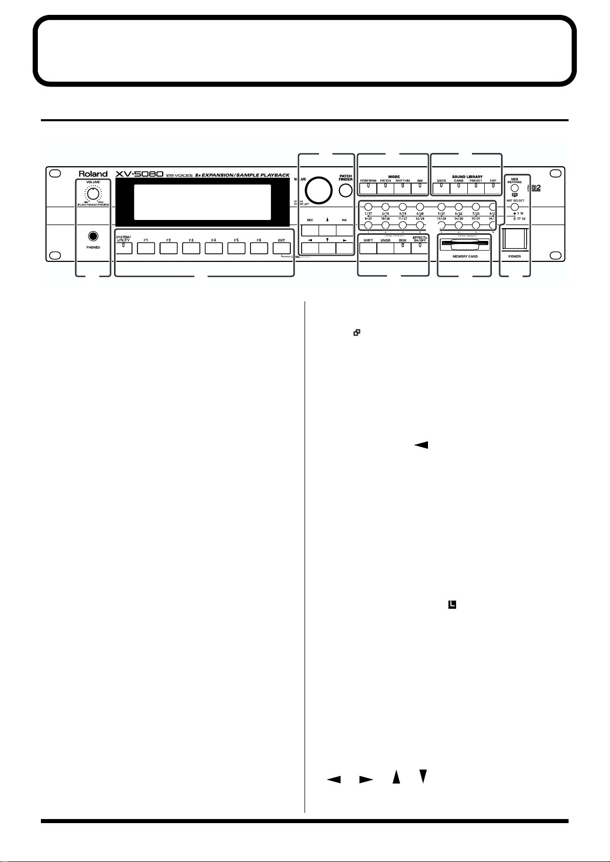
Front Panel
fig.0-001
B
AA
C
A
VOLUME Knob (PHRASE PREVIEW)
This adjusts the volume from the A (MIX) OUTPUT jacks and
PHONES jacks. The volume from the OUTPUT B, C and D jacks
cannot be adjusted.
You can press the knob to listen to the XV-5080 without using
any external devices. (Phrase Preview function; p. 16)
PHONES Jack
Headphones are plugged in here. (Quick Start; p. 11)
D
E
F
G
H I
The function name is shown in the display.
When “” appears next to the function name in the lower row
of the screen, it means that there are one or more further pages.
Press the corresponding [F1]-[F6] buttons to switch to such
pages.
J
[EXIT]
Press this button when you wish to return to the basic display, or
to cancel an operation before executing it.
Hold [EXIT] and press [ ] to hear the demo songs. (Quick
Start; p. 14)
B
Display
The display presents a variety of information about the
operation being performed.
C
[SYSTEM/UTILITY]
The screen displayed switches each time the button is pressed,
rotating through the System mode, Utility mode, and original
screens.
System Mode (the indicator is lit)
This allows you to make settings that affect the entire XV-5080.
Utility Mode (the indicator is blinking)
This allows you to perform operations such as saving, copying,
initializing, transferring data, write-protecting data, and factory
reset operations.
[F1]–[F6]
The functions of these buttons change depending on the selected
page.
D
VALUE Dial (SOUND LIST)
Use this to modify the values of a setting. If you hold down
[SHIFT] as you turn the VALUE dial, the parameter’s value will
change by larger increments.
Press this dial in Patch/Rhythm Set mode to display a list
showing the collection of your favorite sounds. (p. 207)
Pressing the VALUE dial while “” appears in the upper right
of the screen displays the list for the screen.
[PATCH FINDER]
You can select a Patch using the Patch Finder function. (p. 19)
[INC]/[DEC] (Increment/Decrement)
Use these to modify the values of a setting. If you keep on holding
down one button while pressing the other, the value change
accelerates. If you press one of these buttons while holding down
[SHIFT], the value will change in bigger increments.
[] [] [] []
Use these buttons to move the cursor.
12
Page 13

Panel Descriptions
E (MODE)
[PERFORM] (Performance)
Pressed to get into Performance mode. (p. 17)
Press this button while holding down [SHIFT] to switch to Part
Play mode, enabling you to make changes to the settings for the
Patch and Rhythm Set assigned to each Part. (p. 167)
[PATCH]
Pressed to get into Patch mode. (p. 17)
[RHYTHM] (Rhythm Set)
Selects Rhythm Set mode. (p. 17)
[GM]
Press this to enter General MIDI mode. (p. 17)
F (SOUND LIBRARY)
[USER]
Selects a sound from the USER library. (p. 18)
H
[SHIFT]
This is used in combination with other buttons. Holding down
this button changes the functions of other buttons.
[UNDO]
Use this to restore a modified parameter value to its original
setting.
[DISK]
Selects Disk mode.
[EFFECTS ON/OFF]
Use this to turn the internal effects (Multi-effects, Chorus,
Reverb) on or off. (p. 24)
I
MEMORY CARD Slot
A memory card (SmartMedia) can be inserted here. (p. 195)
[CARD]
Selects a sound from an installed memory card, sold separately.
(p. 18)
[PRESET]
Selects a sound from the PRESET library. (p. 18)
[EXP]
Selects a sound from a Wave Expansion Board (sold separately).
(p. 18, Quick Start; p. 22)
G
PART SELECT [1/17]–[16/32]
Selects a Part whose settings you wish to change. (p. 160)
Switches each Part on or off. (p. 159)
TONE SWITCH [1]–[4]
Switches each Tone on or off. (p. 126)
J
[MIDI MESSAGE/RX] (MIDI Message
Indicator/Receive Switch)
MIDI MESSAGE: This will light when a MIDI message is
received.
RX: This turns Parts on and off in Performance mode and GM
mode. (p. 159)
[1-16/17-32]
This specifies whether the PART SELECT [1/17]–[16/32] buttons
will select Parts 1–16 or Parts 17–32.
When this button is lit, Parts 17–32 can be selected.
POWER Switch
Turns the XV-5080’s power on and off. (Quick Start; p. 12)
TONE SELECT [1]–[4]
Selects a Tone whose settings you wish to change. (p. 134)
[A]–[H]
Selects a sound from the Sound Library.
13
Page 14
Panel Descriptions
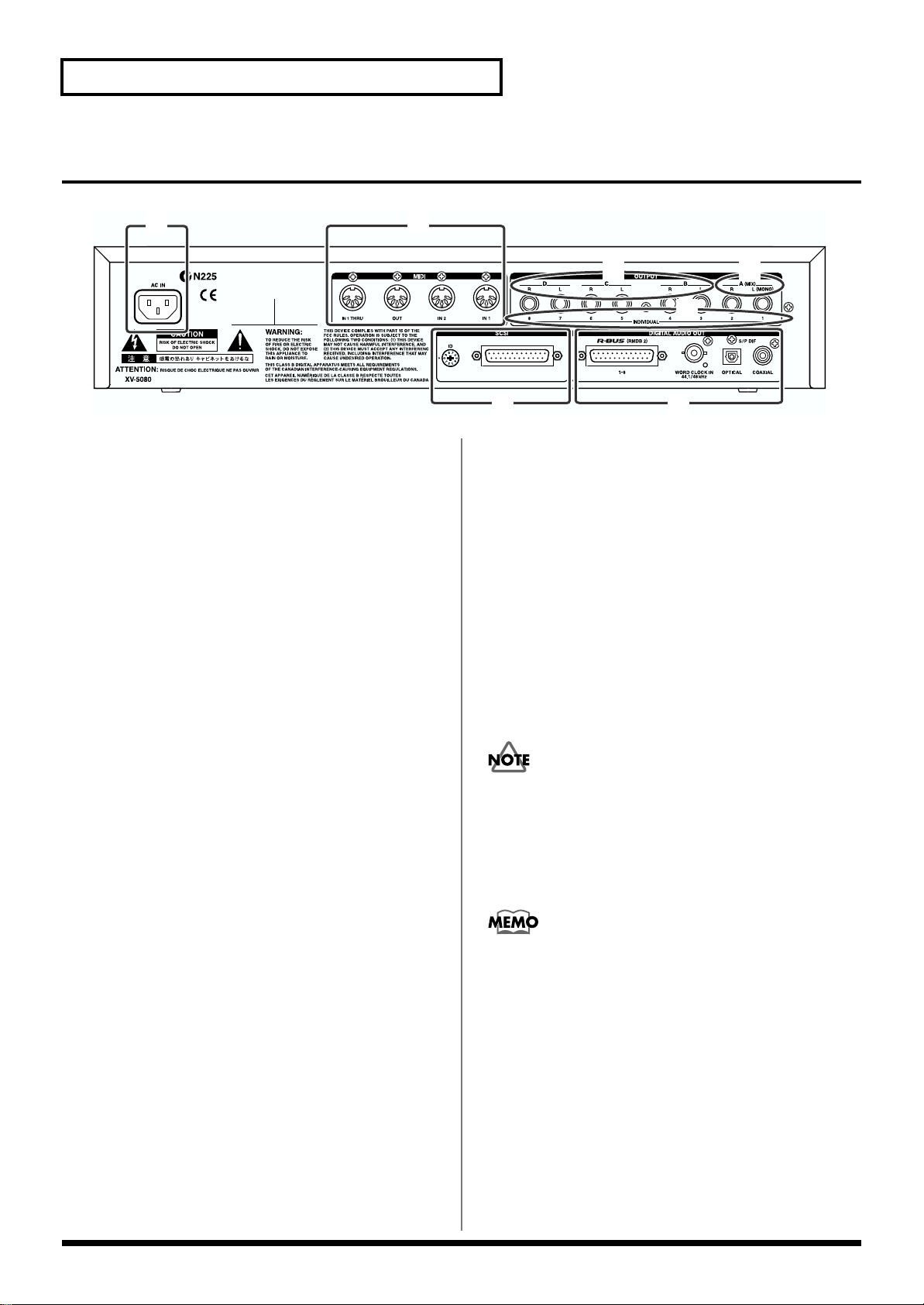
Rear Panel
fig.0-002
K
L
K
AC IN (AC Inlet)
Connect the included power cable here. (Quick Start; p. 11)
L (MIDI)
MIDI Connectors (IN 1/2, OUT, THRU)
These connectors connect the XV-5080 with other MIDI
devices, enabling the sending and receiving of MIDI
messages. (Quick Start; p. 11)
IN 1, 2: Receive messages from other MIDI devices.
OUT: Transmits messages to a MIDI device.
THRU: MIDI messages received at MIDI IN 1 are re-
transmitted without change from this connector.
M (OUTPUT)
A (MIX) OUTPUT Jacks (L (MONO), R)
These jacks send audio signals in stereo (L/R) from the XV5080 to an amp or mixer. For mono output, use the L jack.
(Quick Start; p. 11)
These jacks are used when the SYSTEM SETUP Mix/Parallel
parameter is set to “MIX.” (p. 109, p. 112, p. 116, p. 118)
* The XV-5080, as shipped from the factory, routes the output of
all PRESET Patches to these jacks.
N (OUTPUT)
B, C, D OUTPUT Jacks (L, R)
N
M
O
PQ
O (OUTPUT)
1–8 INDIVIDUAL OUTPUT Jacks
These jacks output audio signals in mono to an amp or
mixer. (Quick Start; p. 11)
P (DIGITAL AUDIO OUT)
R-BUS (RMDB 2) Connector (OUTPUT AD/1-8)
8-out 24 bit digital audio connector. Use this for connecting
to the device such as Roland VM-3100Pro and DIF-AT.
Only the R-BUS devices listed in the Owner’s Manual may be
connected to the R-BUS (RMDB2) connector. Be careful not to
connect any other devices (such as SCSI-type devices, RS232C-type devices, parallel-type devices, etc.) even though
they have similar-looking connectors. Use only a specially
designed R-BUS (RMDB2) cable to make connections.
RMDB II, RMDB 2, and R-BUS refer to the same Roland
standard.
WORD CLOCK IN Connector (44.1/48
kHz)
This is a connector for input of the word clock used for
synchronizing external digital devices (BNC type). (p. 124)
* The XV-5080’s digital out is not compatible with sampling
frequencies (word clock) other than 44.1 or 48 kHz.
These jacks send audio signals in stereo (L/R) from the XV5080 to an amp or mixer. (Quick Start; p. 11)
14
Page 15

S/P DIF OUT Connector
The XV-5080 features both optical and coaxial digital out
connectors (conforming to S/P DIF).
S/P DIF: This is a digital interface format used for consumer
digital audio devices.
* About the Optical Connector Protecting Cap
• If you remove the protecting cap, be sure to keep in a
safe place to prevent loss.
• Always place the protecting cap on the optical connector
when the connector is not in use.
• If you use the optical connector, be sure that the
connector cover you removed is placed out of the reach
of children.
Q
Panel Descriptions
SCSI Connector
This is a DB-25 type SCSI connector for connecting SCSI
devices such as a CD-ROM drive, a Zip disk drive or a hard
disk drive.
Rotate the ID switch to set the SCSI ID numbers so that none
of the devices have the same ID number. (p. 239)
* On the XV-5080, “8” and “9” of the ID switch are not used.
15
Page 16
Chapter 1 Selecting and Playing a Sound
Auditioning Sounds on the XV-5080 (Phrase Preview)
The Phrase Preview feature allows you to audition Patches
on the XV-5080 even when it’s not connected to a MIDI
keyboard or sequencer. You can preview a Patch using a
Phrase that’s appropriate to the Patch’s type or category.
1. Press [PATCH], getting its indicator to light.
2. Turn the VALUE dial, or press [INC]/[DEC] to select the
desired Patch.
3. Press and hold the VOLUME knob.
The phrase prepared for the Patch will play while the knob is
pushed.
* When you preview a Rhythm Set, the XV-5080 plays a
percussion Phrase. Phrase Preview also allows you to audition
a Performance — when you preview a Performance, you hear a
Phrase appropriate to the currently selected Part.
* A USER Patch or a Patch from an optional Wave Expansion
Board (SRX/SR-JV80 series) may not preview in its normal
pitch range. If this occurs, press [ ] or [ ] (Octave Shift
function; p. 23) to select the desired pitch range.
* If the pitch range of a Phrase is wider than the range of the
Tones within a Patch (p. 132), or wider than the range of a
Part within a Performance (p. 161), any notes in the Phrase
that fall outside that range will not be heard.
4. Either by rotating the VALUE dial or by pressing [INC]/
[DEC], set the value.
5. Press [EXIT] to return to the previous page.
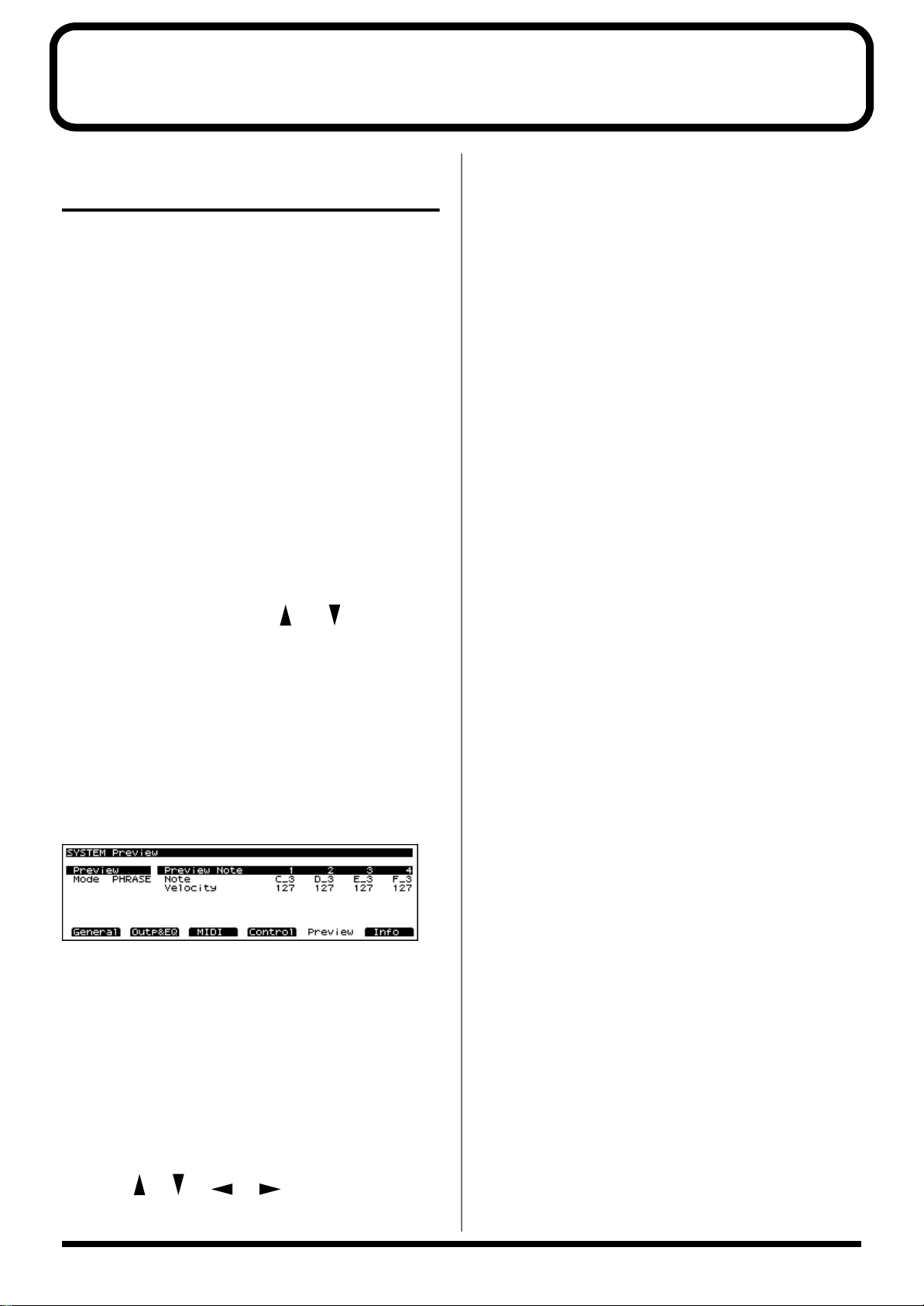
Preview Mode
PHRASE: The Phrase associated with the Patch’s type/
category is played.
CHORD: The notes specified by PREVIEW KEY will play
together as a chord.
SINGLE: The notes specified by PREVIEW KEY will sound
one after another.
Preview 1–4 Note Number
Specifies the four notes (C -1–G9) that will be heard during a
preview when “SINGLE” or “CHORD” is selected for
Preview Mode.
* If “PHRASE” is selected for Preview Mode, these settings will
have no effect.
Preview 1–4 Velocity
Specifies the volume (0–127) of the four notes that will sound
when “SINGLE” or “CHORD” is selected for Preview Mode.
* If “PHRASE” is selected for Preview Mode, these settings will
have no effect.
Setting the Way In Which Sounds Are Previewed
fig.01-000.e_70
You can preview a Patch in any of three ways: “PHRASE”
(the Patch plays a Phrase), “CHORD” (the Patch plays a
chord), or “SINGLE” (the Patch plays a series of notes).
1. Press [SYSTEM/UTILITY], getting the indicator to light.
The System page will appear.
* If the indicator is blinking, you are in UTILITY mode. In this
case, press [SYSTEM/UTILITY] once again to make its
indicator light.
2. Press [F5 (Preview)].
3. Press [ ]/[ ]/[ ]/[ ] to move the cursor to
the parameter you want to set.
16
Page 17
Chapter 1 Selecting and Playing a Sound
Chap.1
Playing a Patch on the XV5080 from External MIDI
Devices (MIDI Keyboard)
The XV-5080 produces sound in response to MIDI messages
that it receives from an external MIDI device such as a MIDI
keyboard or sequencer. In order for this to occur, the MIDI
transmission channels of the external device must match the
MIDI reception channels of the XV-5080.
For details on setting the MIDI transmission channels of your
external MIDI device, refer to its owner’s manual.
Setting the XV-5080’s MIDI Reception Channels
In Patch mode
In order to play single Patches, set the XV-5080’s MIDI
reception channel as follows.
1. Press [SYSTEM], getting the indicator to light.
* If the indicator is blinking, you are in UTILITY mode. In this
case, press [SYSTEM/UTILITY] once again to make its
indicator light.
2. Press [F3 (MIDI)].
3. Use the [ ]/[ ] button to move the cursor to “Patch
Receive Channel.”
4. Either by rotating the VALUE dial or by pressing [INC]/
[DEC], set the value.
5. After making the setting, press [EXIT].
Parts of a Performance
In order to play any of the 16 Parts in a Performance, you
must set the MIDI reception channel for the Part.
1. Select the Performance you wish to use.
2. Press [F4 (MIDI)].
3. Press one of the [1/17]–[16/32] buttons to select the Part
you want to set. To select Parts 17–32, press [1-16/17-32],
getting its indicator to light, and then press the desired
PART SELECT [1/17]–[16/32] button.
The indicator will light, and the Part number will appear in
the upper right of the screen.
4. Press [ ]/[ ] to move the cursor to “Channel.”
5. Turn the VALUE dial or press [INC]/[DEC] to select the
desired value.
6. After making the setting, press [EXIT].
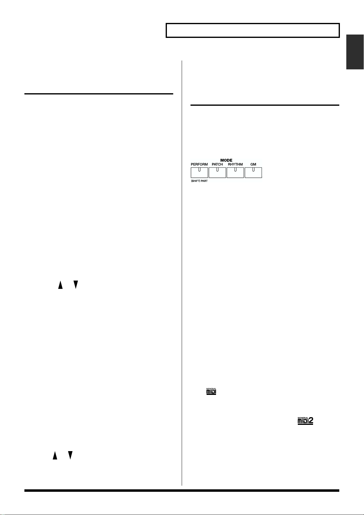
Selecting a Mode (Patch, Performance, or Rhythm Set)
In addition to Patch mode, the XV-5080 also features three
other modes: Performance mode, Rhythm Set mode, and
GM2 mode.
You can easily switch modes simply by pressing the MODE
button (PERFORM/PATCH/RHYTHM/GM) for each mode.
fig.01-001.e
PERFORM (Performance Mode)
In this mode, the XV-5080 functions as a multi-timbral sound
generator, and Performance settings can be modified.
PATCH (Patch Mode)
In this mode, you can play an individual Patch from the
keyboard or modify Patch settings.
RHYTHM (Rhythm Set Mode)
This is how you can play a Rhythm Set from the keyboard
and modify the Rhythm Set settings. XV-5080 Rhythm Sets
can also be used for any Part in a Performance when in
Performance mode.
GM (General MIDI2 Mode)
In this mode, the XV-5080 functions as a General MIDI 2compatible sound generator.
General MIDI is a set of recommendations which seeks to
provide a way to go beyond the limitations of proprietary
designs, and standardize the MIDI capabilities of sound
generating devices. Sound generating devices and music files
that meet the General MIDI standard bear the General MIDI
logo ( ). Music files bearing the General MIDI logo can
be played back using any General MIDI sound generating
unit to produce essentially the same musical performance.
The upwardly compatible General MIDI 2 ( )
recommendations pick up where the original General MIDI
left off, offering enhanced expressive capabilities, and even
greater compatibility. Issues that were not covered by the
original General MIDI recommendations, such as how
sounds are to be edited, and how effects should be handled,
have now been precisely defined. Moreover, the available
sounds have been expanded. General MIDI 2 compliant
17
Page 18
Chapter 1 Selecting and Playing a Sound
sound generators are capable of reliably playing back music
files that carry either the General MIDI or General MIDI 2
logo. In some cases, the conventional form of General MIDI,
which does not include the new enhancements, is referred to
as “General MIDI 1” as a way of distinguishing it from
General MIDI 2.
Patches, Rhythm Sets and Performances can be stored in the
following memory locations within each library group.
PATCH RHYTHM PERFORM
USER 1–128 1, 2, 3, 4 1–64
CARD * * *
PR-A 1–128 1, 2 1–32
PR-B 1–128 1, 2 1–32
PR-C 1–128 1, 2 —
PR-D 1–128 1, 2 —
PR-E 1–128 1, 2 —
PR-F 1–128 1, 2 —
PR-G 1–128 1, 2 —
PR-H 1–256 1, 2, 3, 4 —
XP-A * * —
: : : :
XP-H * * —
You can directly select Tones contained on the card — even
without loading the files into the USER memory — by
assigning banks (CD-A through CD-H) to the files on the
card.
PRESET
The PRESET library group contains the sounds that are
permanently stored in the XV-5080’s memory. Performances
are found only in PR-A and B. However, you can modify its
sounds and save them as new sounds in the USER group.
EXP (Expansion)
Select this group to use the tones stored on wave expansion
boards (SRX Series, SR-JV80 Series; sold separately) inserted
in the EXP-A through -H slots. You cannot alter the contents
of the EXP group, though you can modify its sounds and
save them as new sounds in the USER group. The number of
Patches and Rhythm Sets in the EXP group depends on the
specific wave expansion boards installed. The EXP group
contains no Performances. (Precautions When Installing
Wave Expansion Board (Quick Start; p. 3))
* It is not possible to select an EXP Patch unless a wave
expansion board is inserted into the corresponding slot.
* CARD sounds can be selected only if a SmartMedia card is
inserted into the MEMORY CARD slot.
–: None *: Differs by type
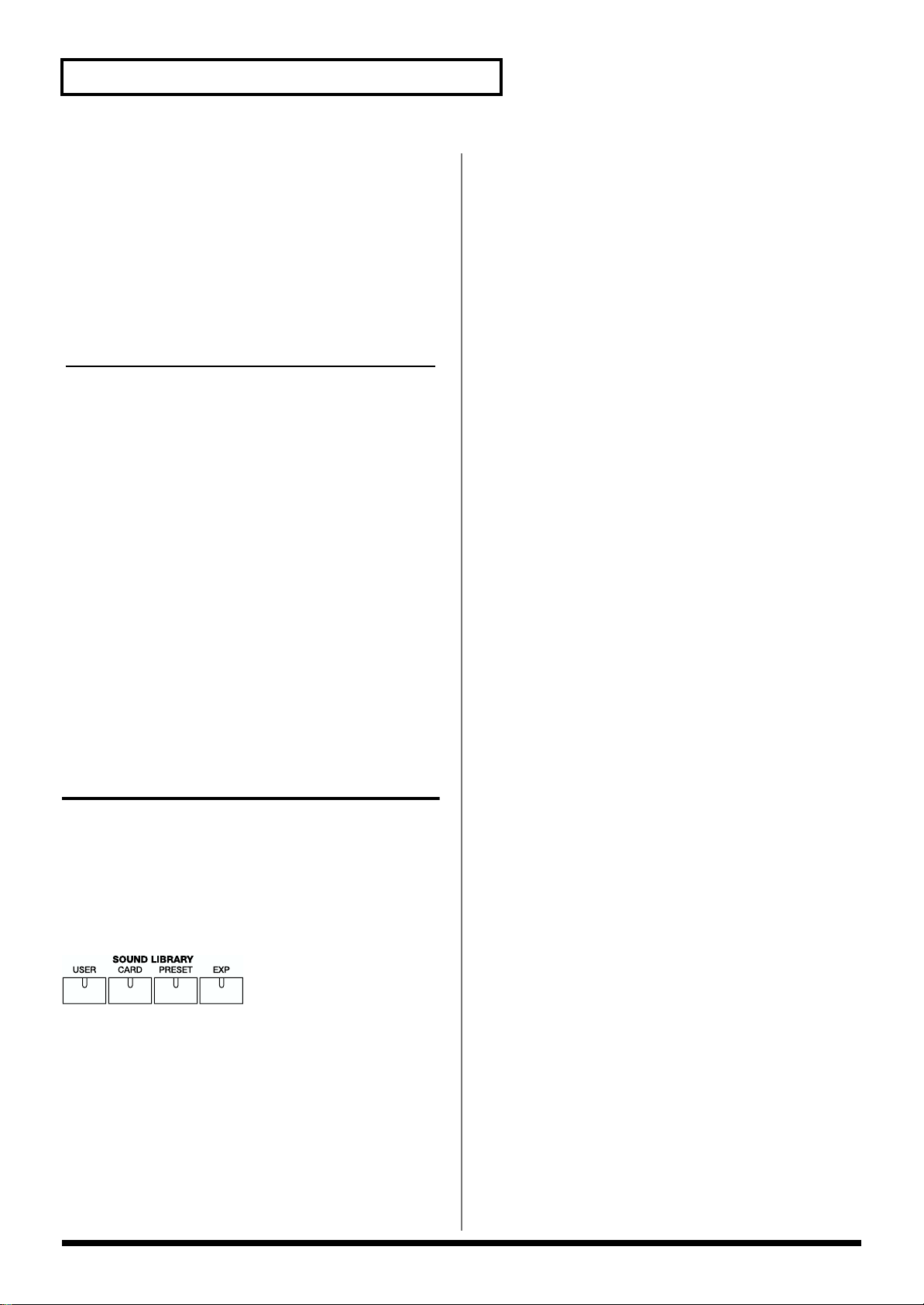
Selecting Sound Libraries
On the XV-5080, tone data is stored in what are called
“SOUND LIBRARY.” The SOUND LIBRARY is divided into
four “groups”: USER, CARD, PRESET, and EXP.
You can easily select the desired group simply by pressing
the SOUND LIBRARY button (USER/CARD/PRESET/EXP)
for each group.
fig.01-002.e
USER
You can store your own Patches, Rhythm Sets and
Performances in the SOUND LIBRARY’s USER group. Save
the tones that you create to this library.
CARD
This library uses sounds from a commercially available
memory card (SmartMedia) inserted into the MEMORY
CARD slot.
18
Page 19
Chapter 1 Selecting and Playing a Sound
Chap.1
Selecting a Patch
Basic Procedure for Selecting a Patch
Turn the VALUE dial or press [INC]/[DEC] to select the
desired Patch.
VALUE Dial
To move quickly through the available Patches:
Turn the VALUE dial while pressing it or, if you prefer, turn
the VALUE dial while pressing [SHIFT].
[INC]/[DEC]
To move quickly upward through the available Patches:
Hold down [INC] and press [DEC]. Alternatively, hold down
[SHIFT] and press [INC].
To move quickly downward through the available
Patches:
Hold down [DEC] and press [INC]. Alternatively, hold down
[SHIFT] and press [DEC].
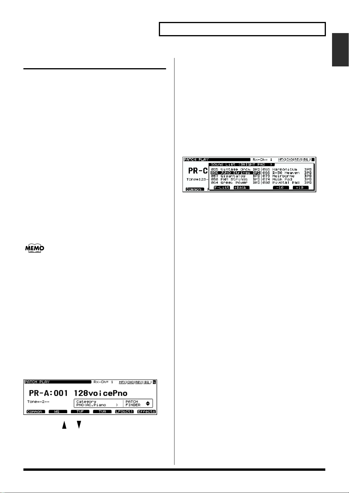
If you want to get even more information, carry out the
following operation.
3. Press the VALUE dial.
The Group List window will appear.
4. Rotate the VALUE dial to select a group.
5. Press [F6 (Select)] to call up the Category List window.
6. By rotating the VALUE dial, move the cursor to the
desired Patch, and then press [F6 (Select)].
The Patches of the selected category will be displayed in
sets of 10.
ig.01-003a.e_70
7. Pressing the [VOLUME] knob (PHRASE PREVIEW)
allows you to audition the selected Patch.
8. Press the VALUE dial (SOUND LIST) to return to the
PATCH PLAY page.
When you hold down [INC] or [DEC], you may eventually
arrive at the beginning (001) of the selected bank (A–H). To
continue selecting Patches, release and then press the desired
[INC] or [DEC] button again.
Selecting Patches by Category (Patch Finder)
The XV-5080’s “Patch Finder” allows you to quickly find any
Patch.
1. Press the [PATCH] button, lighting the indicator.
2. Press the [PATCH FINDER] button, lighting the
indicator.
The categories will appear in the PATCH PLAY page.
fig.01-003.e_70
You can press [ ]/[ ] to select the desired category.
At this point, you can select patches within the currently
selected category, either by rotating the VALUE dial, or by
using the [INC]/[DEC] button.
19
Page 20
Chapter 1 Selecting and Playing a Sound
The following categories can be selected.
Category
Group Category Contents
— NO ASSIGN No assign
Piano
PNO AC.PIANO Acoustic Piano
EP EL.PIANO Electric Piano
Keys&Organ
KEY KEYBOARDS Other Keyboards
(Clav, Harpsichord etc.)
BEL BELL Bell, Bell Pad
MLT MALLET Mallet
ORG ORGAN Electric and Church Organ
ACD ACCORDION Accordion
HRM HARMONICA Harmonica, Blues Harp
Guitar
AGT AC.GUITAR Acoustic Guitar
EGT EL.GUITAR Electric Guitar
DGT DIST.GUITAR Distortion Guitar
Bass
BS BASS Acoustic & Electric Bass
SBS SYNTH BASS Synth Bass
Orchestral
STR STRINGS Strings
ORC ORCHESTRA Orchestra Ensemble
HIT HIT&STAB Orchestra Hit, Hit
WND WIND Winds (Oboe, Clarinet etc.)
FLT FLUTE Flute, Piccolo
Rhythm&SFX
PRC PERCUSSION Percussion
SFX SOUND FX Sound FX
BTS BEAT&GROOVE Beat and Groove
DRM DRUMS Drum Set
CMB COMBINATION Other Patches which use
Split and Layer
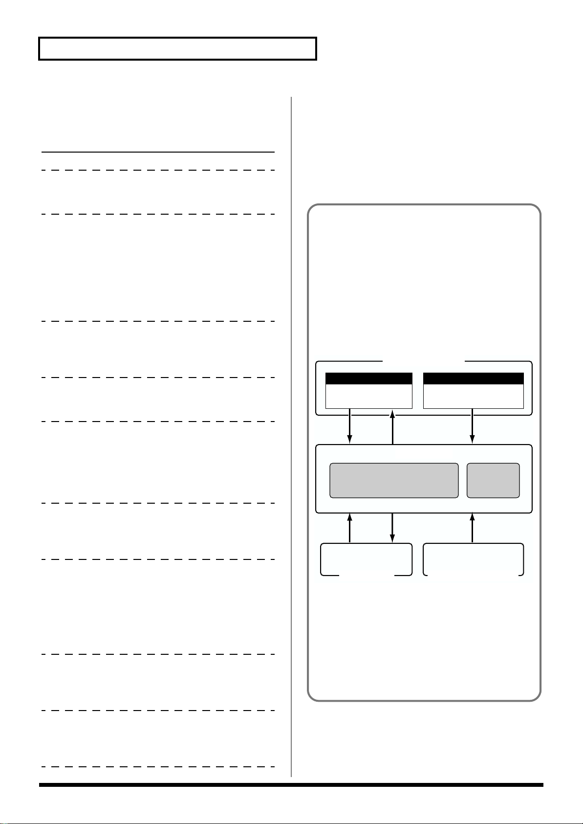
Internal organization
When you select a sound, the sound data is loaded into a
temporary part of memory known as the Temporary
Area. The XV-5080 will produce sound according to the
data in this temporary area.
The data in the temporary area will
• change whenever you select a different sound.
• be lost when the power is turned off.
Internal Memory
Rewritable memory
USER
Write
Temporary Area
Performance
Non-rewritable memory
PR-A, B, C, E
PR-D (General MIDI)
SelectSelect
Patch
Rhythm Set
Brass
BRS AC.BRASS Acoustic Brass
SBR SYNTH BRASS Synth Brass
SAX SAX Sax
Synth
HLD HARD LEAD Hard Synth Lead
SLD SOFT LEAD Soft Synth Lead
TEK TECHNO SYNTH Techno Synth
PLS PULSATING Pulsating Synth
FX SYNTH FX Synth FX (Noise etc.)
SYN OTHER SYNTH Poly Synth
Pad
BPD BRIGHT PAD Bright Pad Synth
SPD SOFT PAD Soft Pad Synth
VOX VOX Vox, Choir
Ethnic
PLK PLUCKED Plucked (Harp etc.)
ETH ETHNIC Other Ethnic
FRT FRETTED Fretted Inst (Mandolin etc.)
SelectSelect
DATA Card
Write
XP-A, B, C, D, E, F, G, H
Wave Expansion Board
When you edit a Performance, Patch or Rhythm Set,
your modifications affect only the data that was loaded
into the temporary area. Since the data in the temporary
area is temporary, you will need to use the Write
operation if you wish to keep the modified data. (p. 194)
20
Page 21
Chapter 1 Selecting and Playing a Sound
Chap.1
Selecting Patches and Rhythm Sets from an External MIDI Device
By receiving MIDI messages, the XV-5080 can switch Patches
(including the Patches for each Part of a Performance) or
Rhythm Sets.
In Patch or Rhythm Set modes
1. Press [PATCH] — or [RHYTHM] if you wish to select a
Rhythm Set — to make the button’s indicator light.
2. Set the transmission channel of your external MIDI
device to match Patch Receive Channel (p. 212), the XV5080’s MIDI reception channel.
To learn about the MIDI settings of your external MIDI
device, see its owner’s manual.
3. Transmit the appropriate Bank Select MSB (Controller
#0) value to the XV-5080.
If the value is “87,” a Patch is selected. If the value is “86,” a
Rhythm Set is selected.
4. Transmit the appropriate Bank Select LSB (Controller
#32) value to the XV-5080.
5. Transmit the Program Change value corresponding to
the Patch or Rhythm Set.
The desired Patch or Rhythm Set will be selected on the XV-
5080.
* When the XV-5080 receives only Program Change messages
without receiving Bank Select messages, it will switch to the
corresponding Patch or Rhythm Set from the currently
selected group or bank.
The Patches and Rhythm Sets in each library correspond to
Bank Select numbers as follows.
Patches
Patch Patch Bank Select Program
Group Number Number Number
MSB LSB
USER 001–128 87 00 001–128
PR-A 001–128 87 64 001–128
PR-B 001–128 87 65 001–128
PR-C 001–128 87 66 001–128
PR-D 001–128 87 67 001–128
PR-E 001–128 87 68 001–128
PR-F 001–128 87 69 001–128
PR-G 001–128 87 70 001–128
CD-A 001–128 87 32 001–128
:::::
CD-H 001–128 87 39 001–128
XP-A *1 *1 *1 *1
:: : ::
XP-H *1 *1 *1 *1
* 1 Depends on the Wave Expansion Board installed.
Fixed Bank Select numbers are assigned to the Wave
Expansion Board itself.
Patch Patch Bank Select
Group Number Number
MSB LSB
SR-JV80-01 001–128 89 00
SR-JV80-01 129–256 89 01
SR-JV80-02 001–128 89 02
SR-JV80-02 129–256 89 03
:
SR-JV80-65 001–128 91 00
SR-JV80-65 129–256 91 01
21
Page 22
Chapter 1 Selecting and Playing a Sound
Rhythm Sets
Rhythm Set Rhythm Set Bank Select Program
Group Number Number Number
MSB LSB
USER 1, 2, 3, 4 86 00 1, 2, 3 , 4
PR-A 001, 002 86 64 001, 002
PR-B 001, 002 86 65 001, 002
PR-C 001, 002 86 66 001, 002
PR-D 001, 002 86 67 001, 002
PR-E 001, 002 86 68 001, 002
PR-F 001, 002 86 69 001, 002
PR-G 001, 002 86 70 001, 002
CD-A 1, 2, 3, 4 86 32 1, 2, 3, 4
: ::::
CD-H 1, 2, 3, 4 86 39 1, 2, 3, 4
XP-A *1 *1 *1 *1
: ::::
XP-H *1 *1 *1 *1
* 1 Depends on the Wave Expansion Board installed.
Fixed Bank Select numbers are assigned to the Wave
Expansion Board itself.
Rhythm Set Rhythm Set Bank Select
Group Number Number
MSB LSB
5. Transmit the Program Change value.
The desired Performance will be selected.
* When the XV-5080 receives a Program Change message
without Bank Select messages, the corresponding Performance
in the currently selected group or bank will be chosen.
You can select any Performance Part’s Patch or Rhythm Set
via MIDI. To learn how, refer to “Assigning a different Patch
to Part (p. 162)” in the XV-5080 QUICK START.
The Performances in each group correspond to the Bank
Select numbers as follows.
Performances
Performance Performance Bank Select Program
Group Number Number Number
MSB LSB
USER 001–064 85 00 001–064
PR-A 001–032 85 64 001–032
PR-B 001–032 85 65 001–032
CD-A 001–064 85 32 001–064
:::::
CD-H 001–064 85 39 001–064
When Patch/Rhy Rx Ch and Perform Ctrl Ch are set to the
same channel, both Bank Select and Program Change are
sent, making it possible to switch among Patches, Rhythm
Sets, and Performances.
SR-JV80-01 001–128 88 00
SR-JV80-01 129–256 88 01
SR-JV80-02 001–128 88 02
SR-JV80-02 129–256 88 03
:
SR-JV80-65 001–128 90 00
SR-JV80-65 129–256 90 01
In Performance mode
1. Press [PERFORM], getting its indicator to light.
2. Set the transmission channel of your external MIDI
device to match the XV-5080’s Performance Control
Channel (p. 212).
To learn about the MIDI settings of your external MIDI
device, see its owner’s manual.
3. Transmit the appropriate Bank Select MSB (Controller
#0) value to the XV-5080.
4. Transmit the appropriate Bank Select LSB (Controller
#32) value to the XV-5080.
Using MIDI to Switch between Patch,
Performance and General MIDI 2
Modes
You can switch between Patch, Performance, and General
MIDI 2 modes by transmitting the appropriate System
Exclusive (Sys Ex) message to the XV-5080, as listed below.
(Sys Ex messages are constructed using hexadecimal
notation.)
To switch to Patch/Rhythm Set (Sys Ex.)
F0 41 10 00 10 12 00 00 00 00 01 7F F7
To switch to Performance
F0 41 10 00 10 12 00 00 00 00 00 00 F7
To switch to GM2 mode
F0 41 10 00 10 12 00 00 00 00 03 7F F7
The third byte of the MIDI message indicates the device ID
number, and the factory setting is “10.” (This is “10” in
hexadecimal notation; in decimal this would be 16.) (This
device ID number will appear as 17 in the display of the XV-
5080. The transmitted messages will use a value of one less
than this (16).) If you have modified the device ID number (p.
22
Page 23
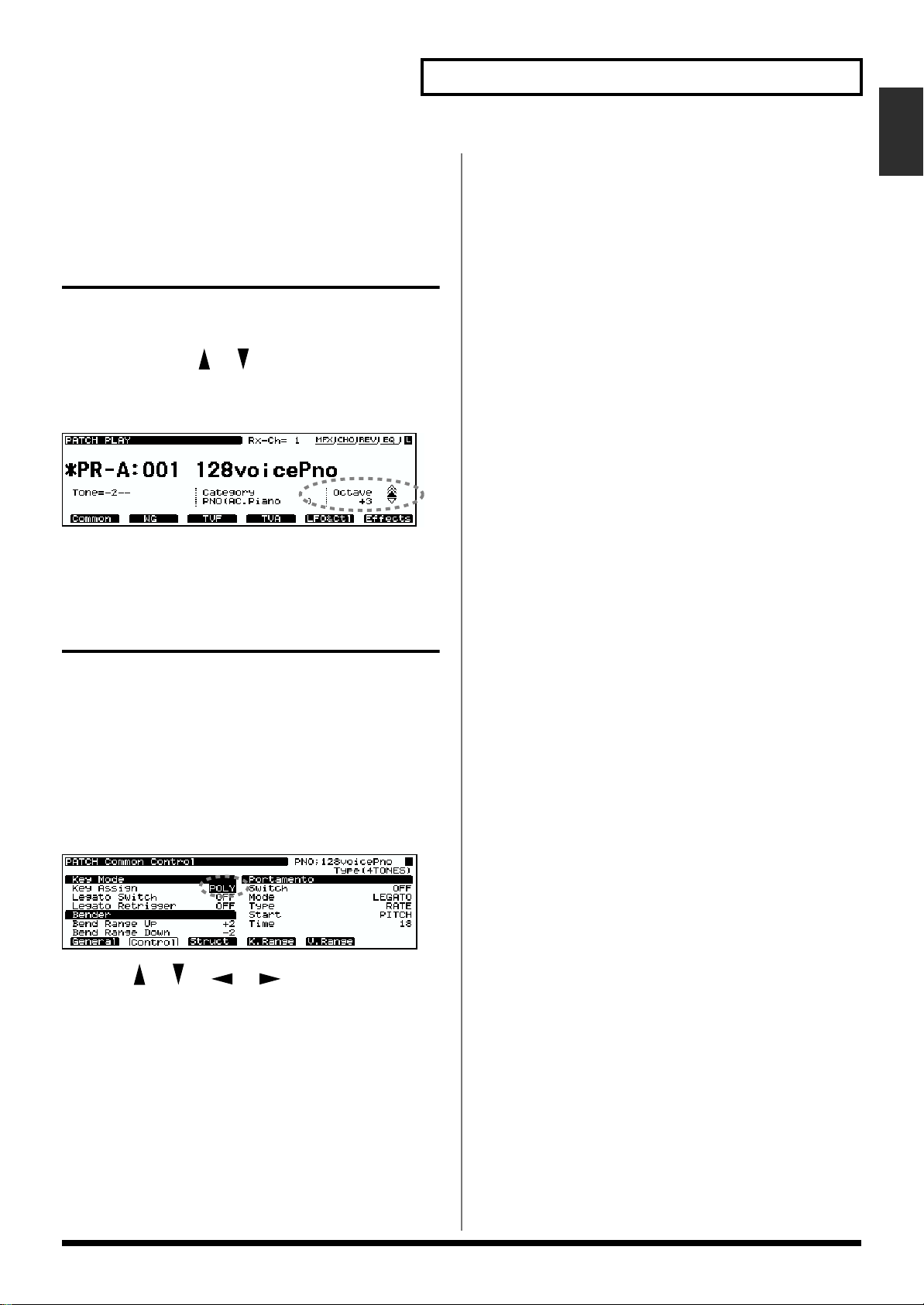
212), modify the third byte to the appropriate value when
transmitting the above exclusive message.
Setting a Patch’s Pitch in Octave Steps (Octave Shift)
In Patch mode, you can easily change the pitch of an entire
Patch.
Each time you press [ ]/[ ], the pitch will change in oneoctave steps. You can adjust a Patch’s pitch by as much as +/
- 3 octaves.
fig.01-004.e
Chapter 1 Selecting and Playing a Sound
Chap.1
Selecting How a Patch Will Play (Polyphonic/ Monophonic)
You can set whether a Patch will play multiple notes at the
same time (Polyphonic) — for example, when you play a
chord or legato line — or whether only the last-played note
will be heard (Monophonic).
1. Select the Patch you wish to use. (p. 19)
2. Press [F1 (Common)].
3. Press [F2 (Control)].
fig.01-005.e
4. Press [ ]/[ ]/[ ]/[ ] to move the cursor to
“Mono/Poly.”
5. Turn the VALUE dial, or press [INC]/[DEC] to select the
desired value.
6. After making the setting, press [EXIT].
23
Page 24
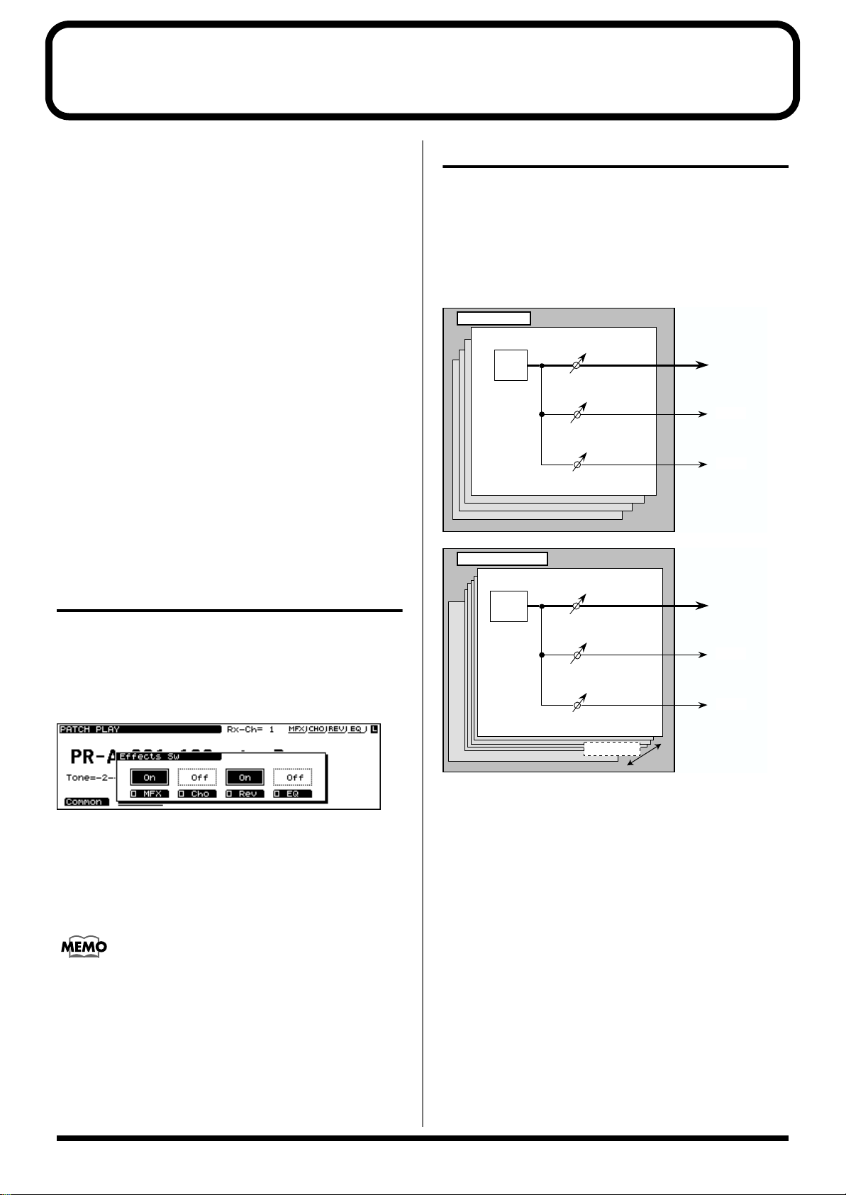
Chapter 2 Using the XV-5080 Effects
The XV-5080 contains four independent effects units.
Multi-effects
The Multi-effects offers 90 different effects. In addition to
effects consisting of only one effect, such as distortion and
delay, the 90 types also include a number of compound
effects, which are formed by combining a number of effects.
Furthermore, the multi-effects effect types also include
chorus and reverb, although the chorus and reverb described
below can be applied as separate effects systems. The XV5080 features three Multi-effects systems in Performance
mode, with each multi-effect independently controllable.
Chorus
Chorus adds depth and spaciousness to the sound.
Reverb
Reverb adds ambience — such as the sound of a concert hall
or auditorium—to sounds.
Equalizer
An equalizer lets you boost or cut specified frequency ranges
of a sound to adjust the tone.
* Equalizer is set in System mode (p. 211).
Turning Effects On/Off
You can turn any of the XV-5080’s effect units—Multi-effects,
Chorus, Reverb, and EQ—on or off using a single procedure.
1. Press the [EFFECTS ON/OFF] button.
The EFFECTS On/Off window will appear.
fig.02-001.e_70
Patch Mode Settings
You can make separate Multi-effects, chorus, and reverb
settings to each Four-Tone Patch and Multi-Partial Patch,
with the same effects applied to each Tone or Partial. You can
control the amount of effect to be applied to each Tone or
Partial by adjusting its send level with respect to the Multieffects, Chorus and Reverb.
fig.02-002.e
4 TONE Patch
fig.02-003.e
Multi-Partial Patch
A0
C8
TONE
Partial
Multi-Effects
Chorus
Reverb
Multi-Effects
Chorus
Reverb
2. ress the [F2]–[F5] button corresponding to the effect to
switch that effect on or off.
The display of the setting will be turned on and off.
3. Press the [EFFECTS ON/OFF] button, getting its
indicator light to go out.
You might, for example, want to turn effects off when
creating a new Patch so that you can hear what it sounds like
without effects. You may also want to turn off the XV-5080’s
effects when you wish to use external effect devices instead
of the built-in effects.
24
88 Partials
Preliminarily, the settings for effects involves determining
Tone Output Assign for Four-Tone Patches, and Split Key
Output Assign for Multi-Partial Patches.
In keeping with the intended usage, choose from the
following setting values for Tone Output Assign.
MFX: Selected when the Multi-effects, chorus, and reverb are
used.
A-D: Selected when outputting in stereo without use of the
Multi-effects. Chorus and reverb can be used.
1-8: Selected when outputting in mono without Multieffects. Chorus and reverb can be used. When this setting is
used, chorus and reverb sounds are output in stereo
according to the Chorus Output Assign and Reverb Output
Assign settings.
Page 25
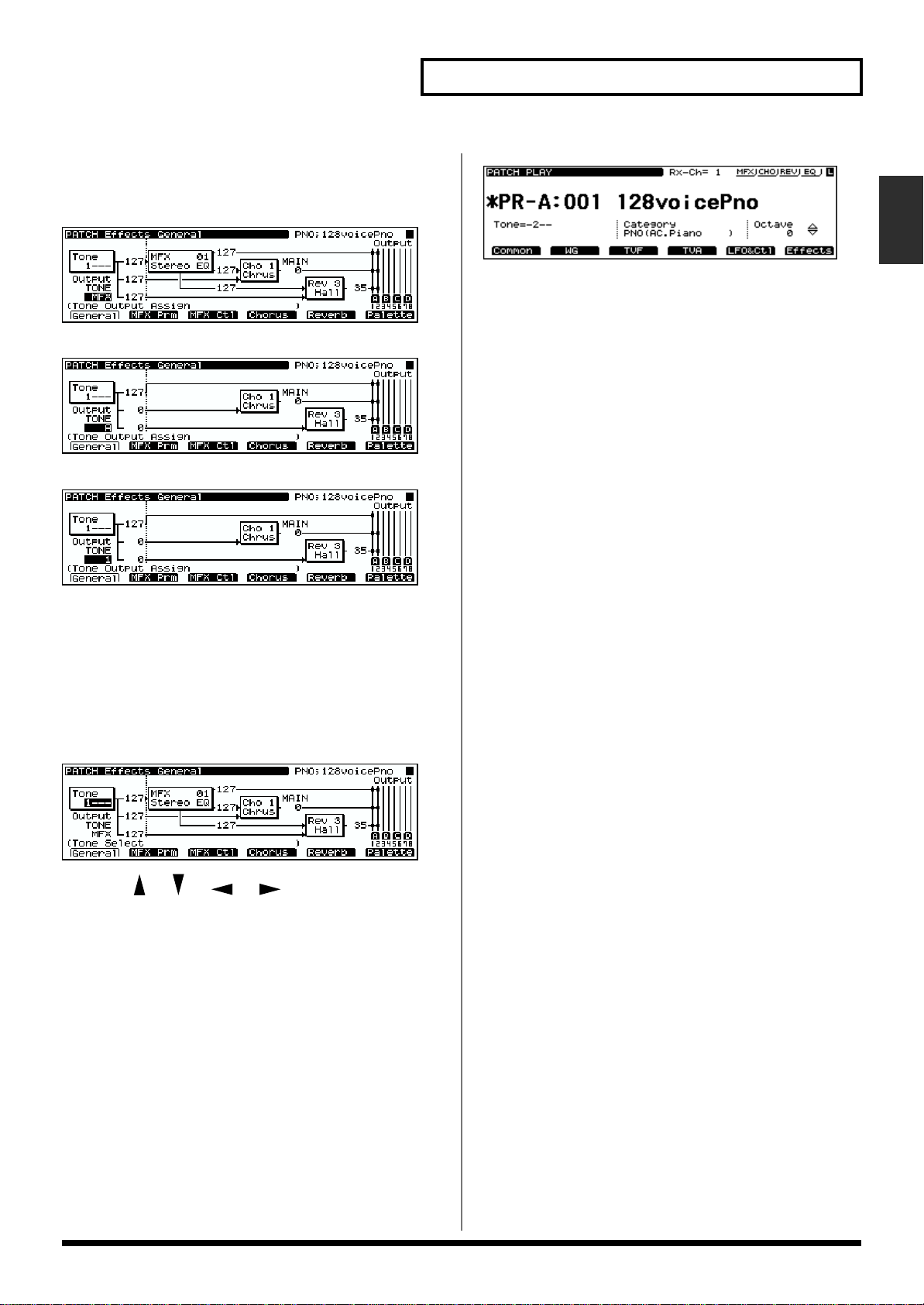
Chapter 2 Using the XV-5080 Effects
The screen appears as shown below, according to the settings
values.
• For MFX
fig.02-004.e_70
• For A–D
fig.02-005.e_70
• For 1–8
fig.02-006.e_70
The following shows the basic setting procedure.
1. Select the Patch you wish to work with.
2. Press [F6 (Effects)].
The Patch Effect page appears.
3. Press [F1 (General)].
The General page will appear.
fig.02-007.e_70
fig.02-008.e_70
* If you turn off the power or select another Patch while the “*”
symbol is displayed, your new Patch settings will be lost. If
you wish to keep them, perform the Write operation. (p. 194)
* With Multi-Partial Patches, pressing [F6 (MIDISel)] allows
you to select the Partial to be edited from the MIDI keyboard.
* When [MFX], [CHO], or [REV] are turned off, effects
processors that are turned off will be indicated by a dashed
outline in the General page.
* When the General page is accessed, you can press [F6
(Palette)] to view the settings for all four Tones together in a
single screen. This allows you to compare the settings of each
Tone as you make settings. When you press [F6 (
→
Tone 1)],
the General page will reappear. [F6] will display the Tone
number to which you will return.
Split Key Edit Mode
When editing Multi-Partial Patches, this sets the key ranges
to which settings are applied.
Settings Values
1KEY: Settings are made for each key individually.
PTL: Settings are applied to all keys to which corresponding
Partials are assigned.
ALL: Settings are applied to all keys to which all Partials are
assigned.
Chap.2
4. Press [ ]/[ ]/[ ]/[ ] to move the cursor to
the parameter you want to set.
5. Turn the VALUE dial, or press [INC]/[DEC] to select the
desired value.
* If you make a mistake when setting a parameter’s value, or you
don’t like the change you have made, just press [UNDO] to
restore the value the parameter originally had.
6. Repeat Steps 3 to 5 to set the Effect.
7. Press [EXIT] to return to the PATCH Play page.
A “*” symbol will appear at the left of the Patch name,
indicating that its settings have been modified.
Routing Tones to Effects
This sets the output destination and level for the currently
selected Tone and Partial, as well as its send level with
respect to the Chorus and Reverb.
On the Effects General page, set the following parameters.
Output Assign
MFX: The Tone is sent into the Multi-effects. Its output
destination is determined by the Multi-effects output
settings.
A–D: The Tone is sent to one of the four output-jack stereo
pairs, OUTPUTS A–D.
1–8: The Tone is sent to the INDIVIDUAL output jacks 1–8.
25
Page 26
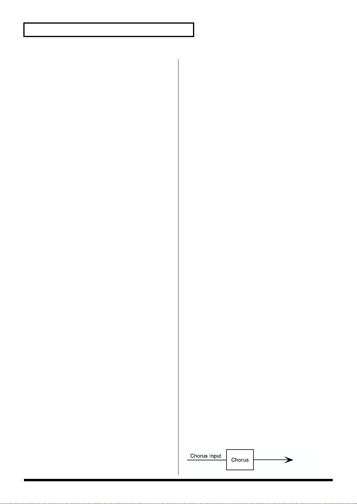
Chapter 2 Using the XV-5080 Effects
Dry Send Level
Range: 0–127
This sets the level of the signal sent to the output destination
set with Output Assign.
Chorus Send Level 0–127
Sets how much of the Tone is sent to the Chorus.
Reverb Send Level 0–127
Sets how much of the Tone is sent to the Reverb.
Making Multi-Effects Settings
This page allows you to establish various settings for the
Multi-effects processor, including its parameters and outputjack assignment.
On the Effects General page, set the following parameters.
MFX Type (Multi-effects Type)
Use this parameter to select from among the 90 available
Multi-effects. For a description of these effects, check out
“Parameters for Each Multi-Effect (MFX TYPE)” (p. 41).
MFX Dry Send Level 0–127
Determines the level of the Multi-effects processor’s output
to the OUTPUT jacks.
MFX Chorus Send Level 0–127
Determines the level of the post-Multi-effects processor
signal sent to Chorus.
Pressing [F3 (MFX Ctl)] in the Effects General page calls up
the MFX Control page, in which you can make the following
settings.
MFX Control 1–4 Source
Select the Control Source to be used for changing the Multieffects parameters, and set the Sens and parameters to be
changed by that Control Source.
OFF: No controller is used.
CC01–95: Controller numbers 1–95 (except for 32)
PITCH BEND: Pitch Bend
AFTERTOUCH: Aftertouch
SYS-CTRL 1–4: System control 1–4
MFX Control Destination 1–4
Selects the Multi-effects parameter to be controlled using the
MFX Control 1–4 source. The parameters that can be selected
depend on which type of Multi-effects is set to MFX Type.
MFX Control 1–4 Sens -63– +63
If you wish to modify the selected parameter in a positive (+)
direction—i.e., a higher value, toward the right, or faster,
etc.—from its current setting, select a positive (+) value. If
you wish to modify the selected parameter in a negative (-)
direction—i.e., a lower value, toward the left, or slower,
etc.—from its current setting, select a negative (-) value.
Higher numbers produce a greater amount of change.
Making Chorus Settings
MFX Reverb Send Level 0–127
Determines the level of the post-Multi-effects processor
signal sent to Reverb.
MFX Output Assign A–D
Specifies the OUTPUT jacks to which the signal, after it has
passed through the Multi-effects, is to be routed.
Pressing [F2 (MFX Prm)] in the Effects General page calls up
the MFX Param page, in which you can make the following
settings.
MFX A–D Parameter
These parameters allow you to customize the selected MultiEffect. For a description of the parameters, check out
“Parameters for Each Multi-Effect (MFX TYPE)” (p. 41).
The XV-5080’s Chorus effect unit can also be used as a stereo
delay unit.
These settings allow you to select chorus or delay, the
characteristics of the selected effect type, and the Chorus
output routing.
On the Effects General page, set the following parameters.
Chorus Type
0 (Off): Neither Chorus or Delay is used.
1 (Chrus): Chorus is used.
2 (Delay): Delay is used.
Chorus Output Select
This parameter allows you to send the Chorus output
directly to the currently selected OUTPUT jacks, to the
Reverb, or to both.
MAIN: The Chorus output is sent only to the OUTPUT jacks.
fig.02-009.e
OUTPUT
26
Page 27
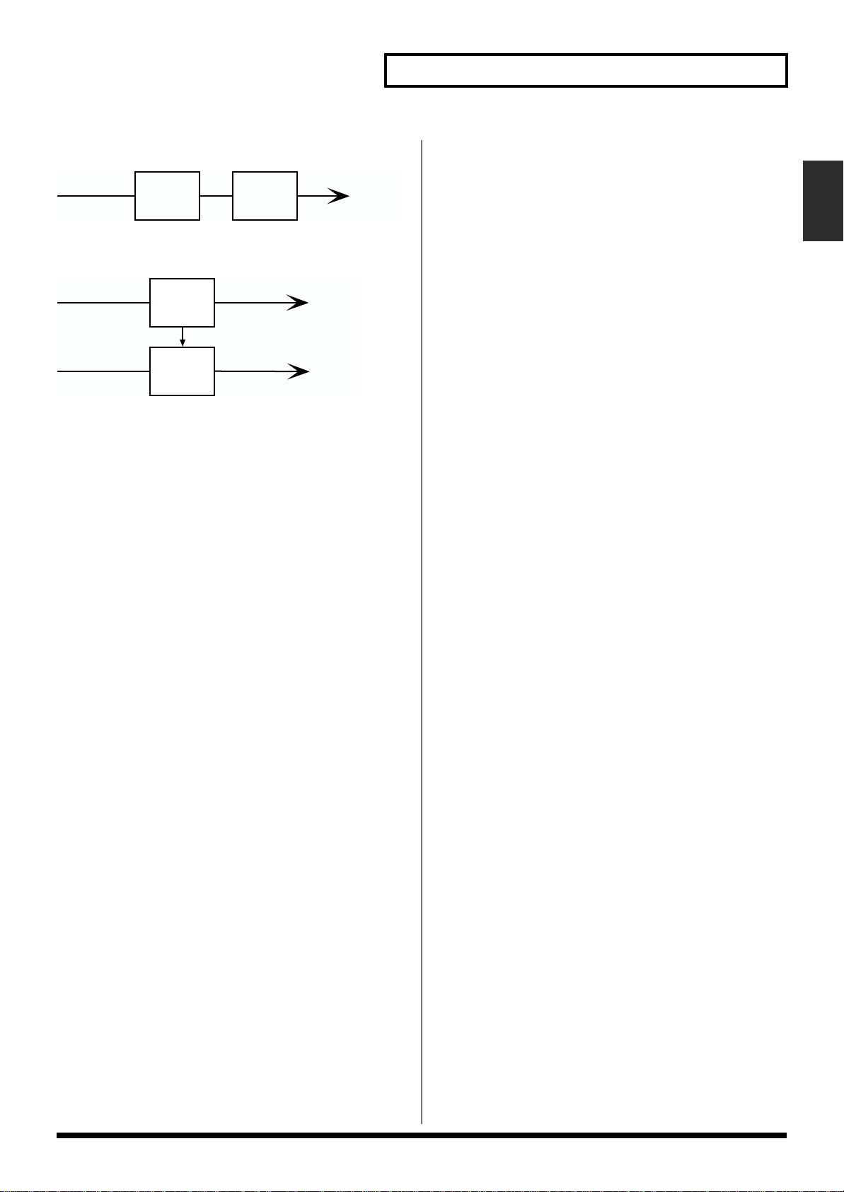
Chapter 2 Using the XV-5080 Effects
REV: The Chorus output is sent only to the Reverb.
fig.02-010.e
Chorus Input
M+R: The Chorus output is sent to the OUTPUT jacks and to
the Reverb.
fig.02-011.e
Chorus Input
Reverb Input
Chorus
Chorus
Reverb
Reverb
OUTPUT
OUTPUT
OUTPUT
Chorus Level 0–127
Determines the Chorus output level.
Chorus Output Assign A–D
Selects the pair of OUTPUT jacks to which the Chorus unit’s
stereo output is routed when Chorus Output Select is set to
“MAIN” or “M+R.”
HPF: Frequencies lower than the selected cutoff frequency
value are eliminated.
Cutoff freq (Cutoff Frequency) *1
Sets the cutoff frequency when a specific frequency band is
cut off by a filter.
*1 200, 250, 315, 400, 500, 630, 800, 1000, 1250, 1600, 2000,
2500, 3150, 4000, 5000, 6300, 8000 Hz
• For Type: 2 (DELAY)
Center (Delay Center) 200–1000 ms, Note
Sets the delay time for the delay located at the center of the
stereo field.
Left (Delay Left) 200–1000 ms, Note
Sets the delay time for the delay located at the left side of the
stereo field.
Right (Delay Right) 200–1000 ms, Note
Sets the delay time for the delay located at the right side of
the stereo field.
Chap.2
Pressing [F4 (Chorus)] in the General page calls up the
Chorus page, in which you can make the following settings.
• For Type: 1 (CHORUS)
Rate (Chorus Rate) 0.05–10.00 Hz
Adjusts the modulation speed of the chorus effect.
Depth (Chorus Depth) 0–127
Adjusts the modulation depth of the chorus effect.
Feedback (Chorus Feedback) 0–127
Specifies the amount of the chorus effect’s output to be
returned - fed back - to its input. Higher settings will create a
more complex Chorus effect.
Phase 0–180 degree
Adjusts the spatial spread of the sound.
Pre Delay (Chorus Pre Delay) 0.0–100 ms
Adjusts the delay time from the direct sound until when the
chorus sound is heard.
Higher settings will make the sound more spacious.
Type (Filter Type)
Selects the type of filter.
OFF: No filter is used.
LPF: Frequencies higher than the selected cutoff frequency
value are eliminated.
HF Damp *1
This allows you to reduce, or “damp,” the high-frequency
content of the repeated feedback delays—frequencies above
the selected value will be damped. If you do not want to cut
the high frequencies of the feedback, set this parameter to
BYPASS.
*1 200, 250, 315, 400, 500, 630, 800, 1000, 1250, 1600, 2000,
2500, 3150, 4000, 5000, 6300, 8000 Hz, BYPASS
Feedback -98– +98%
Adjusts the amount of delay feedback, controlling the
number of times the delay repeats. With negative (-) values,
the phase of the repeated delays is inverted.
Center (Delay Center Level) 0–127
Sets the volume level of the delay located at the center of the
stereo field.
Left (Delay Left Level) 0–127
Sets the volume level of the delay located at the left side of
the stereo field.
Right (Delay Right Level) 0–127
Sets the volume level of the delay located at the right side of
the stereo field.
27
Page 28

Chapter 2 Using the XV-5080 Effects
Making Reverb Settings
These settings allow you to select the desired type of Reverb,
its characteristics, and the pair of OUTPUT jacks to which the
Reverb unit’s stereo output is routed.
On the Effects General page, set the following parameters.
Reverb Type
Selects the type of Reverb.
0 (Off): Reverb is not used.
1 (Revrb): Normal Reverb
2 (Room): This reverb simulates typical room acoustic
reflections.
3 (Hall): This reverb simulates typical concert hall acoustic
reflections.
4 (Plate): This reverb simulates a reverb plate, a popular
type of artificial reverb unit that derives its sound from the
vibration of a metallic plate. You can also achieve unusual
metallic-sounding reverbs using SRV PLATE.
Reverb Level 0–127
Specifies the output level of the Reverb.
HF Damp (Reverb/Delay HF Damp) *1
Specifies the frequency above which the high-frequency
content of the reverb sound will be cut, or “damped.”
Lower values cause a greater range of high frequencies to be
cut, producing a softer reverb sound. If you do not want to
cut the high frequencies of the feedback, set this parameter to
BYPASS.
*1 200, 250, 315, 400, 500, 630, 800, 1000, 1250, 1600, 2000,
2500, 3150, 4000, 5000, 6300, 8000 Hz, BYPASS
Feedback (Delay Feedback)
When the Type setting is DELAY or PAN-DELAY, this adjust
the amount of delay feedback, controlling the number of
delay repeats.
Higher settings will produce more delay repeats.
• For Type: 2 (SRV ROOM)/3 (SRV
HALL)/4 (SRV PLATE)
Pre Delay (Pre Delay Time) 0.0–100 ms
Adjusts the time delay from when the direct sound begins
until the reverb sound is heard.
Reverb Output Assign A–D
Selects the OUTPUT jacks to which the Reverb unit’s stereo
output is routed.
Pressing [F5 (Reverb)] in the General page calls up the
Reverb page, in which you can make the following settings.
• For Type: 1 (REVERB)
Type (Reverb/Delay Type)
Selects a type of reverb or delay.
ROOM1: This is a short reverb with high density.
ROOM2: This is a short reverb with low density.
STAGE1: This is a reverb with greater late reverberation.
STAGE2: This is a reverb with strong early reflections.
HALL1: This is a very clear-sounding reverb.
HALL2: This is a rich reverb.
DELAY: This is a conventional delay effect.
PAN-DELAY: This is a delay effect with echoes that pan left
and right.
Time (Reverb/Delay Time) 0–127
When the Type setting is ROOM1–HALL2, this adjusts the
length of reverberation. When the Type setting is DELAY or
PAN-DELAY, this adjusts the delay time.
Higher settings produce a more spacious ambience.
Time (Reverb Time) 0–127
Adjusts the time length of reverberation.
Size 1–8
Adjusts the size of the simulated room or hall. The size
becomes bigger as the value increases.
High Cut (High Cut Frequency) *1
Sets the frequency above which the high-frequency content
of the reverb will be reduced. If you do not want to damp the
high frequencies, set this parameter to BYPASS.
Density (Reverb Density) 0–127
Adjusts the density of reverb. Higher values result in greater
density.
Diffusion (Reverb Diffusion) 0–127
Adjusts the change in the density of the reverb over time.
The higher the value, the more the density increases with
time. (The effect of this setting is most pronounced with long
reverb times.)
LF Damp Freq (LF Damp Frequency) *2
Specifies the frequency below which the low-frequency
content of the reverb sound will be reduced, or “damped.”
28
Page 29
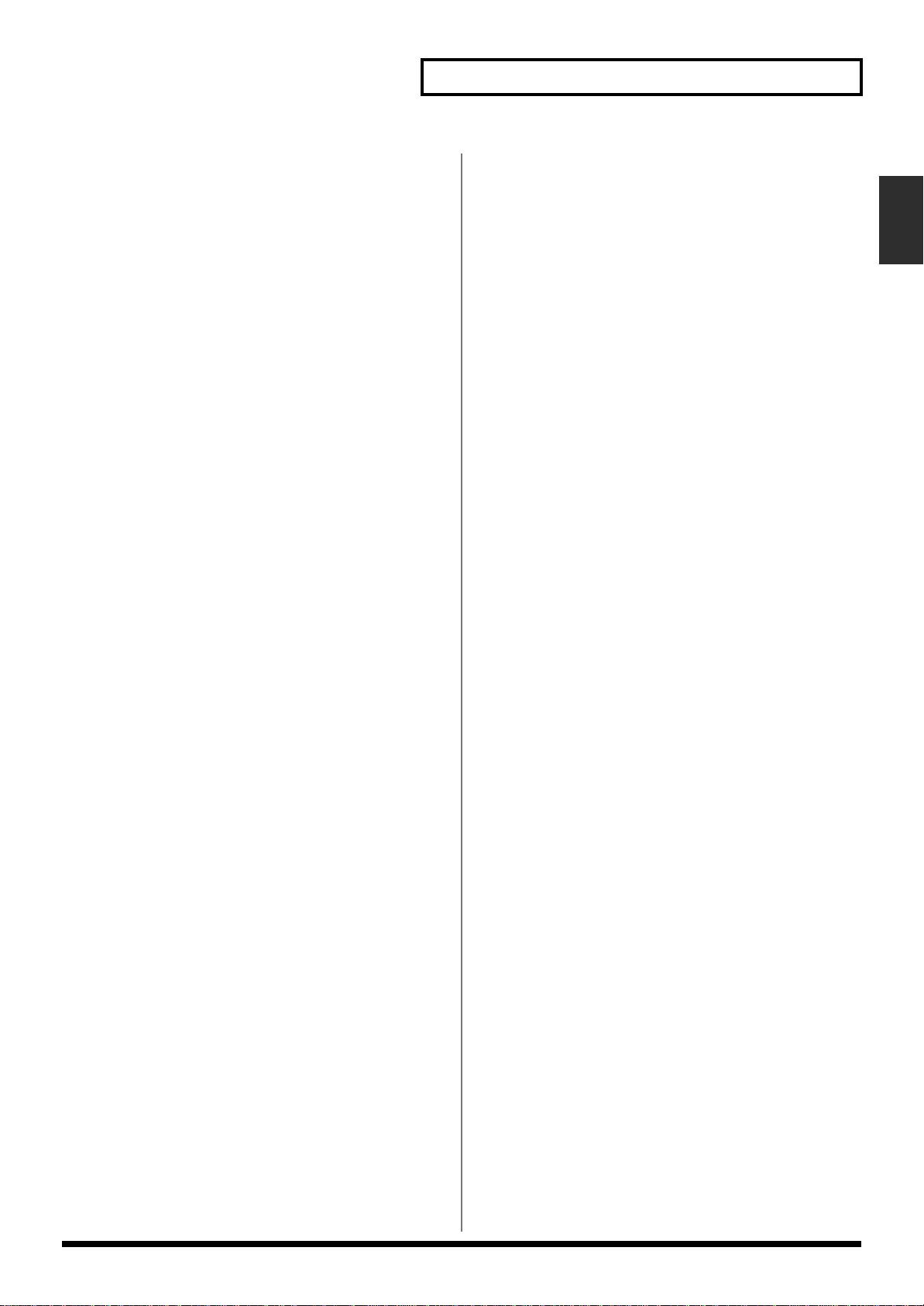
LF Damp Gain -36–0 dB
Adjusts the amount of damping applied to the frequency
range selected with LF Damp. With a setting of “0,” there
will be no reduction of the reverb’s low-frequency content.
HF Damp Freq (LF Damp Frequency) *3
Specifies the frequency above which the high-frequency
content of the reverb sound will be reduced, or “damped.”
HF Damp Gain -36–0 dB
Adjusts the amount of damping applied to the frequency
range selected with HF Damp. With a setting of “0,” there
will be no reduction of the reverb’s high-frequency content.
*1 160, 200, 250, 320, 400, 500, 640, 800, 1000, 1250, 1600,
2000, 2500, 3200, 4000, 5000, 6400, 8000, 10000, 12500
Hz, BYPASS
*2 50, 64, 80, 100, 125, 160, 200, 250, 320, 400, 500, 640, 800,
1000, 1250, 1600, 2000, 2500, 3200, 4000 Hz
Chapter 2 Using the XV-5080 Effects
Chap.2
*3 4000, 5000, 6400, 8000, 10000, 12500 Hz
29
Page 30
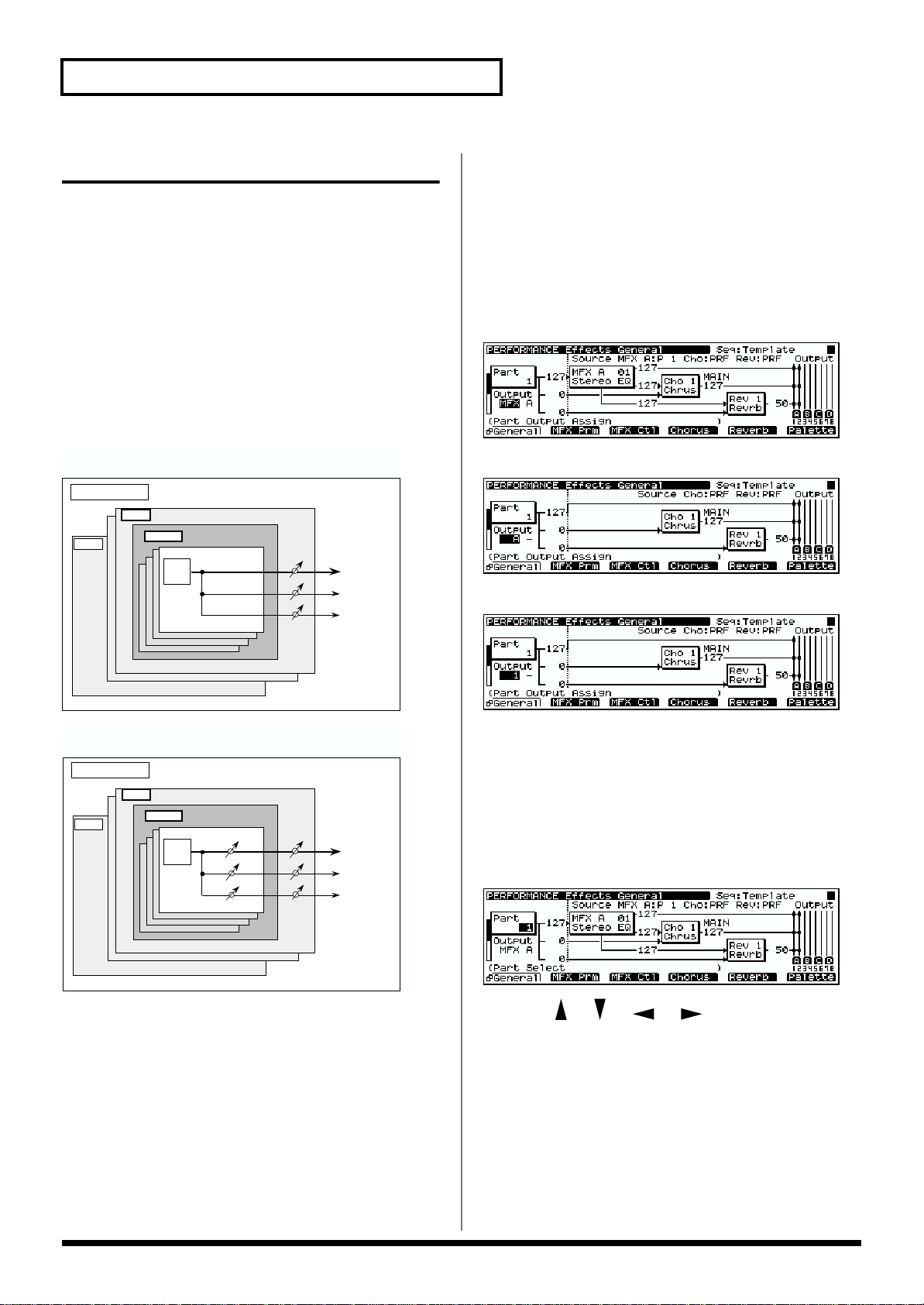
Chapter 2 Using the XV-5080 Effects
Performance Mode Settings
Three different Multi-effects can be used in a Performance.
Select which of these three Multi-effects to use with Part
Output MFX Select. With this parameter, the same Multieffects are applied to all selected Parts. You can adjust the
amount of effect to be applied to the Parts by adjusting their
Send Levels to each of the effect units. (Fig. 1)
The Send Level setting for each Tone can also influence effect
intensity (Fig. 2).
Furthermore, you can take the Multi-effects you have applied
to a Patch in a Part and apply them to the entire
Performance, or just part of the Performance.
fig.02-012.e
Fig.1 – When Output Assign is set to “MFX” in the Performance
mode (the output settings for Tone are ignored)
Performance
Part 1
Part32
Patch
TONE
Multi-Effects
Chorus
Reverb
used, chorus and reverb sounds are output in stereo
according to the Chorus Output Assign and Reverb Output
Assign settings.
PAT: The Part’s output destination is determined by the
settings of the Patch or Rhythm Set assigned to the Part.
The screen appears as shown below, according to the settings
values.
• For MFX
fig.02-014.e_70
• For A–D
fig.02-015.e_70
• For 1–8
fig.02-016.e_70
fig.02-013.e
Fig.2 – When Output Assign is set to “PATCH” in the Performance
mode (the output settings for Tone are valid)
Performance
Part 1
Part32
Patch
TONE
Multi-Effects
Chorus
Reverb
The primary role of the effect settings is to determine the Part
Output Assign.
You can select from the following Part Output Assign
settings values to suit your purposes.
MFX: Selected when Multi-effects, chorus, and reverb are
used.
A-D: Selected when outputting in stereo without use of the
Multi-effects. Chorus and reverb can be used.
1-8: Selected when outputting in mono without Multieffects. Chorus and reverb can be used. When this setting is
The following shows the basic setting procedure.
1. Select the Performance you wish to use.
2. Press [F5 (Effects)].
The Perform Effect page will appear.
3. Press [F1 (General)].
The General page will appear.
fig.02-017.e_70
4. Press [ ]/[ ]/[ ]/[ ] to move the cursor to
the parameter you want to set.
5. Turn the VALUE dial, or press [INC]/[DEC] to select the
desired value.
* If you make a mistake when setting a parameter’s value, or you
don’t like the change you have made, just press [UNDO] to
restore the value the parameter originally had.
6. Repeat Steps 3 to 5 to set the Effect.
7. Press [EXIT] to return to the PERFORM Play page.
30
Page 31

Chapter 2 Using the XV-5080 Effects
A “*” symbol will appear at the left of the Performance name,
indicating that its settings have been modified.
fig.02-018.e_70
* If you turn off the power or select another Performance while
the “*” symbol is displayed, your new Performance settings
will be lost. If you wish to keep these settings, perform the Save
operation. (p. 194)
* When [MFX], [CHO], or [REV] are turned off, effects
processors that are turned off will be indicated by a dashed
outline in the General page.
* When the General page is accessed, you can press [F6
(Palette)] to view the values for eight Parts (Parts 1–8, Parts
9–16, Parts 17–24, or Parts 25–32) in a single screen. This
allows you to compare the settings of each Part as you make
settings. Each time you press [F1], the Part Palette page will
switch between Parts 1–8, Parts 9–16, Parts 17–24, and Parts
25–32. When you press [F6 (
reappear. [F6] will display the Part number to which you will
return.
→
Part 1)], the General page will
Routing Part Outputs
Sets the output destination and level for the selected Part, as
well as its send level with respect to the Chorus and Reverb.
On the Effects General page, set the following parameters.
Part Output Assign
MFX: The Part’s sound is sent into the Multi-effects. Its
output destination is determined by the Multi-effects output
settings.
OUTPUT A–D: The Part is sent to the selected pair of
OUTPUT A–D jacks.
INDIVIDUAL 1–8: The Part is sent to the selected
INDIVIDUAL 1–8 jack.
PATCH: Conforms to the Patch settings.
Part Reverb Send Level 0–127
Sets how much of the Part’s sound is sent to the Reverb.
Making Multi-Effects Settings
This page allows you to make various settings for the Multieffects, including the type, the parameters, and the output
assignments.
On the Effects General page, set the following parameters.
MFX Type (Multi-effects Type)
Use this parameter to select from among the 90 available
Multi-effects. For a description of these effects, check out
“Parameters for Each Multi-Effect (MFX TYPE)” (p. 41).
MFX Dry Send Level 0–127
Determines the level of the signal that is to be sent to the
output jacks, after passing through the Multi-effects.
MFX Chorus Send Level 0–127
Determines the level of the signal that is to be sent to Chorus,
after passing through the Multi-effects.
MFX Reverb Send Level 0–127
Determines the level of the signal that is to be sent to Reverb,
after passing through the Multi-effects.
MFX Output Assign A–D
Selects the OUTPUT jacks to which the Multi-effects stereo
output is routed.
MFX A–C Source
Assigns the MFX settings being used to Multi-effects A–C. If
you wish to use the MFX parameter settings of the
Performance, select PRF. If you wish to use the MFX
parameter settings of the Patch assigned to one of the Parts,
select the Part number (P1–32).
Pressing [F2 (MFX)] in the Effects General page calls up the
MFX Param page, in which you can make the following
settings.
Chap.2
Part Output MFX Select A–C
Selects which of the three Multi-effects is to be used.
Part Dry Send Level
Range: 0–127
This sets the level of the signal sent to the output destination
set with Part Output Assign.
Part Chorus Send Level 0–127
Sets how much of the Part’s sound is sent to the Chorus.
* When you press [F2 (MFX)] once again on this page, the
MFX Control page appears. When you press [F2 (MFX)] once
again, the MFX Param page will reappear.
MFX A–C Parameter
These parameters allow you to customize the selected MultiEffect. For a description of the parameters, check out
“Parameters for Each Multi-Effect (MFX TYPE)” (p. 41).
Pressing [F2 (MFX)] in the MFX Param page calls up the MFX
Control page, in which you can make the following settings.
31
Page 32

Chapter 2 Using the XV-5080 Effects
OUTPUT
Chorus Input
Chorus
Reverb
* When you press [F2 (MFX)] once again, the MFX Param page
will reappear.
MFXA–C Control 1–4 Source
Select the Control Source to be used for changing the Multieffects parameters, and set the Sens and parameters to be
changed by that Control Source.
OFF: No controller is used.
CC01–95: Controller numbers 1–95 (except for 32)
PITCH BEND: Pitch Bend
AFTERTOUCH: Aftertouch
SYS-CTRL 1–4: System control 1–4
MFXA–C Control Destination 1–4
Selects the Multi-effects parameter to be controlled using the
MFX Control 1–4 source. The parameters that can be selected
depend on which type of Multi-effects is set to MFX Type.
MFXA–C Control 1–4 Sens -63– +63
If you wish to modify the selected parameter in a positive (+)
direction—i.e., a higher value, toward the right, or faster,
etc.—from its current setting, select a positive (+) value. If
you wish to modify the selected parameter in a negative (-)
direction—i.e., a lower value, toward the left, or slower,
etc.—from its current setting, select a negative (-) value.
Higher numbers produce a greater amount of change.
Making Chorus Settings
The XV-5080’s Chorus effect unit can also be used as a stereo
delay unit.
These settings allow you to select chorus or delay, the
characteristics of the selected effect type, and the Chorus
output routing.
On the Effects General page, set the following parameters.
Chorus Type
0 (Off): Neither Chorus or Delay is used.
1 (Chrus): Chorus is used.
2 (Delay): Delay is used.
Chorus Source PRF/P1–32
Set this when assigning chorus settings that are used by
another part. Select PRF when using the Performance's
chorus settings. When using the chorus settings assigned to
one of the parts, select the part number (P1–32).
Chorus Output Select
This parameter allows you to send the Chorus output
directly to the currently selected OUTPUT jacks, to the
Reverb, or to both.
MAIN: The Chorus output is sent only to the OUTPUT jacks.
fig.02-019.e
OUTPUT
REV: The Chorus output is sent only to the Reverb.
fig.02-020.e
M+R: The Chorus output is sent to the OUTPUT jacks and to
the Reverb.
fig.02-021.e
Chorus Input
Reverb Input
Chorus
Reverb
OUTPUT
OUTPUT
Chorus Level 0–127
Determines the Chorus output level.
Chorus Output Assign A–D
Selects the pair of OUTPUT jacks to which the Chorus unit’s
stereo output is routed when Chorus Output Select is set to
“MAIN” or “M+R.”
32
Page 33

Chapter 2 Using the XV-5080 Effects
Pressing [F4 (Chorus)] in the General page calls up the
Chorus page, in which you can make the following settings.
• For Type: 1 (CHORUS)
Rate (Chorus Rate) 0.05–10.00 Hz
Adjusts the modulation speed of the chorus effect.
Depth (Chorus Depth) 0–127
Adjusts the modulation depth of the chorus effect.
Feedback (Chorus Feedback) 0–127
Specifies the amount of the chorus effect’s output to be
returned - fed back - to its input. Higher settings will create a
more complex Chorus effect.
Phase 0–180 degree
Adjusts the spatial spread of the sound.
Pre Delay (Chorus Pre Delay) 0.0–100 ms
Adjusts the delay time from the direct sound until when the
chorus sound is heard.
Higher settings will make the sound more spacious.
Type (Filter Type)
Selects the type of filter.
OFF: No filter is used.
LPF: Frequencies higher than the selected cutoff frequency
value are eliminated.
HPF: Frequencies lower than the selected cutoff frequency
value are eliminated.
• For Type: 2 (DELAY)
Center (Delay Center) 200–1000 ms, Note
Sets the delay time for the delay located at the center of the
stereo field.
Left (Delay Left) 200–1000 ms, Note
Sets the delay time for the delay located at the left side of the
stereo field.
Right (Delay Right) 200–1000 ms, Note
Sets the delay time for the delay located at the right side of
the stereo field.
HF Damp *1
This allows you to reduce, or “damp,” the high-frequency
content of the repeated feedback delays—frequencies above
the selected value will be damped. If you do not want to cut
the high frequencies of the feedback, set this parameter to
BYPASS.
*1 200, 250, 315, 400, 500, 630, 800, 1000, 1250, 1600, 2000,
2500, 3150, 4000, 5000, 6300, 8000 Hz, BYPASS
Feedback -98– +98%
Adjusts the amount of delay feedback, controlling the
number of times the delay repeats. With negative (-) values,
the phase of the repeated delays is inverted.
Center (Delay Center Level) 0–127
Sets the volume level of the delay located at the center of the
stereo field.
Chap.2
Cutoff freq (Cutoff Frequency) *1
Sets the cutoff frequency when a specific frequency band is
cut off by a filter.
*1 200, 250, 315, 400, 500, 630, 800, 1000, 1250, 1600, 2000,
2500, 3150, 4000, 5000, 6300, 8000 Hz
Left (Delay Left Level) 0–127
Sets the volume level of the delay located at the left side of
the stereo field.
Right (Delay Right Level) 0–127
Sets the volume level of the delay located at the right side of
the stereo field.
33
Page 34

Chapter 2 Using the XV-5080 Effects
Making Reverb Settings
These settings allow you to select the desired type of Reverb,
its characteristics, and the pair of OUTPUT jacks to which the
Reverb unit’s stereo output is routed.
On the Effects General page, set the following parameters.
Reverb Type
Selects the type of Reverb.
0 (Off): Reverb is not used.
1 (Revrb): Normal Reverb
2 (Room): This reverb simulates typical room acoustic
reflections.
3 (Hall): This reverb simulates typical concert hall acoustic
reflections.
4 (Plate): This reverb simulates a reverb plate, a popular
type of artificial reverb unit that derives its sound from the
vibration of a metallic plate. You can also achieve unusual
metallic-sounding reverbs using SRV PLATE.
Reverb Source
Set this when assigning reverb settings that are used by
another part. Select PRF when using the Performance's
reverb settings. When using the reverb settings assigned to
one of the parts, select the part number (P1–32).
Reverb Level 0–127
Specifies the output level of the Reverb.
Reverb Output Assign A–D
Selects the OUTPUT jacks to which the Reverb unit’s stereo
output is routed.
Pressing [F5 (Reverb)] in the General page calls up the
Reverb page, in which you can make the following settings.
• For Type: 1 (REVERB)
Type (Reverb/Delay Type)
Selects a type of reverb or delay.
ROOM1: This is a short reverb with high density.
ROOM2: This is a short reverb with low density.
STAGE1: This is a reverb with greater late reverberation.
STAGE2: This is a reverb with strong early reflections.
HALL1: This is a very clear-sounding reverb.
HALL2: This is a rich reverb.
DELAY: This is a conventional delay effect.
PAN-DELAY: This is a delay effect with echoes that pan left
and right.
Time (Reverb/Delay Time) 0–127
When the Type setting is ROOM1–HALL2, this adjusts the
length of reverberation. When the Type setting is DELAY or
PAN-DELAY, this adjusts the delay time.
Higher settings produce a more spacious ambience.
HF Damp (Reverb/Delay HF Damp) *1
Specifies the frequency above which the high-frequency
content of the reverb sound will be cut, or “damped.”
Lower values cause a greater range of high frequencies to be
cut, producing a softer reverb sound. If you do not want to
cut the high frequencies of the feedback, set this parameter to
BYPASS.
*1 200, 250, 315, 400, 500, 630, 800, 1000, 1250, 1600, 2000,
2500, 3150, 4000, 5000, 6300, 8000 Hz, BYPASS
34
Feedback (Delay Feedback)
When the Type setting is DELAY or PAN-DELAY, this adjust
the amount of delay feedback, controlling the number of
delay repeats.
Higher settings will produce more delay repeats.
Page 35

• For Type: 2 (SRV ROOM)/3 (SRV
HALL)/4 (SRV PLATE)
Pre Delay (Pre Delay Time) 0.0–100 ms
Adjusts the time delay from when the direct sound begins
until the reverb sound is heard.
Time (Reverb Time) 0–127
Adjusts the time length of reverberation.
Size 1–8
Adjusts the size of the simulated room or hall. The size
becomes bigger as the value increases.
High Cut (High Cut Frequency) *1
Sets the frequency above which the high-frequency content
of the reverb will be reduced. If you do not want to damp the
high frequencies, set this parameter to BYPASS.
Chapter 2 Using the XV-5080 Effects
Chap.2
Density (Reverb Density) 0–127
Adjusts the density of reverb. Higher values result in greater
density.
Diffusion (Reverb Diffusion) 0–127
Adjusts the change in the density of the reverb over time. The
higher the value, the more the density increases with time.
(The effect of this setting is most pronounced with long
reverb times.)
LF Damp Freq (LF Damp Frequency) *2
Specifies the frequency below which the low-frequency
content of the reverb sound will be reduced, or “damped.”
LF Damp Gain -36–0 dB
Adjusts the amount of damping applied to the frequency
range selected with LF Damp. With a setting of “0,” there
will be no reduction of the reverb’s low-frequency content.
HF Damp Freq (LF Damp Frequency) *3
Specifies the frequency above which the high-frequency
content of the reverb sound will be reduced, or “damped.”
HF Damp Gain -36–0 dB
Adjusts the amount of damping applied to the frequency
range selected with HF Damp. With a setting of “0,” there
will be no reduction of the reverb’s high-frequency content.
*1 160, 200, 250, 320, 400, 500, 640, 800, 1000, 1250, 1600,
2000, 2500, 3200, 4000, 5000, 6400, 8000, 10000, 12500
Hz, BYPASS
*2 50, 64, 80, 100, 125, 160, 200, 250, 320, 400, 500, 640, 800,
1000, 1250, 1600, 2000, 2500, 3200, 4000 Hz
*3 4000, 5000, 6400, 8000, 10000, 12500 Hz
35
Page 36

Chapter 2 Using the XV-5080 Effects
Rhythm Set Mode Settings
You can apply Multi-effects, Chorus or Reverb to each of a
Rhythm Set’s Tones. You can control the amount of effect to
be applied to each Rhythm Tone by adjusting its send level to
the Multi-effects, Chorus and Reverb.
fig.02-022.e
Rhythm Set
B1
RHYTHM
D7
TONE
The primary role of the effect settings is to determine the
Rhythm Tone Output Assign.
You can select from the following Rhythm Tone Output
Assign settings values to suit your purposes.
MFX: Selected when Multi-effects, chorus, and reverb are
used.
A-D: Selected when outputting in stereo without use of the
Multi-effects. Chorus and reverb can be used.
1-8: Selected when outputting in mono without Multieffects. Chorus and reverb can be used. When this setting is
used, chorus and reverb sounds are output in stereo
according to the Chorus Output Assign and Reverb Output
Assign settings.
The screen appears as shown below, according to the settings
values.
• For MFX
fig.02-023.e_70
Multi-Effects
Chorus
Reverb
• For 1–8
fig.02-025.e_70
The following shows the basic setting procedure.
1. Select the Rhythm Tone you wish to set.
2. Press [F6 (Effects)].
The Patch Effect page appears.
3. Press [F1 (General)].
The General page will appear.
fig.02-026.e_70
4. Press [ ]/[ ]/[ ]/[ ] to move the cursor to
the parameter you want to set.
5. Turn the VALUE dial or press [INC]/[DEC] to select the
desired value.
* If you make a mistake when setting a parameter’s value, or you
don’t like the change you have made, just press [UNDO] to
restore the value the parameter originally had.
6. Repeat Steps 3 to 5 to set the Effect.
7. Press [EXIT] to return to the RHYTHM Play page.
A “*” symbol will appear at the left of the Rhythm Set name,
indicating that its settings have been modified.
fig.02-027.e_70
• For A–D
fig.02-024.e_70
36
* If you turn off the power or select another Rhythm Set while
the “*” symbol is displayed, your new Rhythm Set settings
will be lost. If you wish to keep them, perform the Write
operation. (p. 194)
* When [MFX], [CHO], or [REV] are turned off, effects
processors that are turned off will be indicated by a dashed
outline in the General page.
Page 37

Chapter 2 Using the XV-5080 Effects
Routing Tones to Effects
This sets the output destination and level for the currently
selected Tone, as well as its send level with respect to the
Chorus and Reverb.
On the Effects General page, set the following parameters.
Rhythm Tone Output Assign
MFX: The Tone is sent into the Multi-effects. Its output
destination is determined by the Multi-effects output
settings.
A–D: The Tone is sent to one of the four output-jack stereo
pairs, OUTPUTS A–D.
1–8: The Tone is sent to the INDIVIDUAL output jacks 1–8.
Rhythm Tone Dry Send Level
Range: 0–127
This sets the level of the signal sent to the output destination
set with Rhythm Output Assign.
Rhythm Tone Chorus Send Level 0–127
Sets how much of the Tone is sent to the Chorus.
Rhythm Tone Reverb Send Level 0–127
Sets how much of the Tone is sent to the Reverb.
Making Multi-Effects Settings
MFX Output Assign A–D
Specifies the OUTPUT jacks to which the signal, after it has
passed through the Multi-effects, is to be routed.
Pressing [F2 (MFX Prm)] in the Effects General page calls up
the MFX Param page, in which you can make the following
settings.
MFX A–C Parameters
These parameters allow you to customize the selected MultiEffect. For a description of the parameters, check out
“Parameters for Each Multi-Effect (MFX TYPE)” (p. 41).
Pressing [F3 (MFX Ctl)] in the Effects General page calls up
the MFX Control page, in which you can make the following
settings.
MFX Control 1–4 Source
Select the Control Source to be used for changing the Multieffects parameters, and set the Sens and parameters to be
changed by that Control Source.
OFF: No controller is used.
CC01–95: Controller numbers 1–95 (except for 32)
PITCH BEND: Pitch Bend
AFTERTOUCH: Aftertouch
SYS-CTRL 1–4: System control 1–4
Chap.2
This page allows you to make various settings for the Multieffects, including the type, the parameters, and the output
assignments
On the Effects General page, set the following parameters.
MFX Type (Multi-effects Type)
Use this parameter to select from among the 90 available
Multi-effects. For a description of these effects, check out
“Parameters for Each Multi-Effect (MFX TYPE)” (p. 41).
MFX Dry Send Level 0–127
Determines the level of the signal that is to be sent to the
output jacks, after passing through the Multi-effects.
MFX Chorus Send Level 0–127
Determines the level of the signal that is to be sent to Chorus,
after passing through the Multi-effects.
MFX Reverb Send Level 0–127
Determines the level of the signal that is to be sent to Reverb,
after passing through the Multi-effects.
MFX Control Destination 1–4
Selects the Multi-effects parameter to be controlled using the
MFX Control 1–4 source. The parameters that can be selected
depend on which type of Multi-effects is set to MFX Type.
MFX Control 1–4 Sens -63– +63
If you wish to modify the selected parameter in a positive (+)
direction—i.e., a higher value, toward the right, or faster,
etc.—from its current setting, select a positive (+) value. If
you wish to modify the selected parameter in a negative (-)
direction—i.e., a lower value, toward the left, or slower,
etc.—from its current setting, select a negative (-) value.
Higher numbers produce a greater amount of change.
37
Page 38

Chapter 2 Using the XV-5080 Effects
Making Chorus Settings
The XV-5080’s Chorus effect unit can also be used as a stereo
delay unit.
These settings allow you to select chorus or delay, the
characteristics of the selected effect type, and the Chorus
output routing.
On the Effects General page, set the following parameters.
Chorus Type
0 (Off): Neither Chorus or Delay is used.
1 (Chrus): Chorus is used.
2 (Delay): Delay is used.
Chorus Output Select
This parameter allows you to send the Chorus output
directly to the currently selected OUTPUT jacks, to the
Reverb, or to both.
MAIN: The Chorus output is sent only to the OUTPUT jacks.
fig.02-028.e
OUTPUT
Pressing [F4 (Chorus)] in the General page calls up the
Chorus page, in which you can make the following settings.
• For Type: 1 (CHORUS)
Rate (Chorus Rate) 0.05–10.00 Hz
Adjusts the modulation speed of the chorus effect.
Depth (Chorus Depth) 0–127
Adjusts the modulation depth of the chorus effect.
Feedback (Chorus Feedback) 0–127
Specifies the amount of the chorus effect’s output to be
returned - fed back - to its input. Higher settings will create a
more complex Chorus effect.
Phase 0–180 degree
Adjusts the spatial spread of the sound.
Pre Delay (Chorus Pre Delay) 0.0–100 ms
Adjusts the delay time from the direct sound until when the
chorus sound is heard.
Higher settings will make the sound more spacious.
REV: The Chorus output is sent only to the Reverb.
fig.02-029.e
Chorus Input
M+R: The Chorus output is sent to the OUTPUT jacks and to
the Reverb.
fig.02-030.e
Chorus Input
Reverb Input
Chorus
Chorus
Reverb
Reverb
OUTPUT
OUTPUT
OUTPUT
Chorus Level 0–127
Determines the Chorus output level.
Chorus Output Assign A–D
Selects the pair of OUTPUT jacks to which the Chorus unit’s
stereo output is routed when Chorus Output Select is set to
“MAIN” or “M+R.”
Type (Filter Type)
Selects the type of filter.
OFF: No filter is used.
LPF: Frequencies higher than the selected cutoff frequency
value are eliminated.
HPF: Frequencies lower than the selected cutoff frequency
value are eliminated.
Cutoff freq (Cutoff Frequency) *1
Sets the cutoff frequency when a specific frequency band is
cut off by a filter.
*1 200, 250, 315, 400, 500, 630, 800, 1000, 1250, 1600, 2000,
2500, 3150, 4000, 5000, 6300, 8000 Hz
38
Page 39

Chapter 2 Using the XV-5080 Effects
• For Type: 2 (DELAY)
Center (Delay Center) 200–1000 ms, Note
Sets the delay time for the delay located at the center of the
stereo field.
Left (Delay Left) 200–1000 ms, Note
Sets the delay time for the delay located at the left side of the
stereo field.
Right (Delay Right) 200–1000 ms, Note
Sets the delay time for the delay located at the right side of
the stereo field.
HF Damp *1
This allows you to reduce, or “damp,” the high-frequency
content of the repeated feedback delays—frequencies above
the selected value will be damped. If you do not want to cut
the high frequencies of the feedback, set this parameter to
BYPASS.
*1 200, 250, 315, 400, 500, 630, 800, 1000, 1250, 1600, 2000,
2500, 3150, 4000, 5000, 6300, 8000 Hz, BYPASS
Feedback -98– +98%
Adjusts the amount of delay feedback, controlling the
number of times the delay repeats. With negative (-) values,
the phase of the repeated delays is inverted.
Making Reverb Settings
These settings allow you to select the desired type of Reverb,
its characteristics, and the pair of OUTPUT jacks to which the
Reverb unit’s stereo output is routed.
On the Effects General page, set the following parameters.
Reverb Type
Selects the type of Reverb.
0 (Off): Reverb is not used.
1 (Revrb): Normal Reverb
2 (Room): This reverb simulates typical room acoustic
reflections.
3 (Hall): This reverb simulates typical concert hall acoustic
reflections.
4 (Plate): This reverb simulates a reverb plate, a popular
type of artificial reverb unit that derives its sound from the
vibration of a metallic plate. You can also achieve unusual
metallic-sounding reverbs using SRV PLATE.
Reverb Level 0–127
Specifies the output level of the Reverb.
Reverb Output Assign A–D
Selects the OUTPUT jacks to which the Reverb unit’s stereo
output is routed.
Chap.2
Center (Delay Center Level) 0–127
Sets the volume level of the delay located at the center of the
stereo field.
Left (Delay Left Level) 0–127
Sets the volume level of the delay located at the left side of
the stereo field.
Right (Delay Right Level) 0–127
Sets the volume level of the delay located at the right side of
the stereo field.
Pressing [F5 (Reverb)] in the General page calls up the
Reverb page, in which you can make the following settings.
39
Page 40

Chapter 2 Using the XV-5080 Effects
• For Type: 1 (REVERB)
Type (Reverb/Delay Type)
Selects a type of reverb or delay.
ROOM1: This is a short reverb with high density.
ROOM2: This is a short reverb with low density.
STAGE1: This is a reverb with greater late reverberation.
STAGE2: This is a reverb with strong early reflections.
HALL1: This is a very clear-sounding reverb.
HALL2: This is a rich reverb.
DELAY: This is a conventional delay effect.
PAN-DELAY: This is a delay effect with echoes that pan left
and right.
Time (Reverb/Delay Time) 0–127
When the Type setting is ROOM1–HALL2, this adjusts the
length of reverberation. When the Type setting is DELAY or
PAN-DELAY, this adjusts the delay time.
Higher settings produce a more spacious ambience.
HF Damp (Reverb/Delay HF Damp) *1
Specifies the frequency above which the high-frequency
content of the reverb sound will be cut, or “damped.”
Lower values cause a greater range of high frequencies to be
cut, producing a softer reverb sound. If you do not want to
cut the high frequencies of the feedback, set this parameter to
BYPASS.
*1 200, 250, 315, 400, 500, 630, 800, 1000, 1250, 1600, 2000,
2500, 3150, 4000, 5000, 6300, 8000 Hz, BYPASS
Feedback (Delay Feedback)
When the Type setting is DELAY or PAN-DELAY, this adjust
the amount of delay feedback, controlling the number of
delay repeats.
Higher settings will produce more delay repeats.
• For Type: 2 (SRV ROOM)/3 (SRV
HALL)/4 (SRV PLATE)
Pre Delay (Pre Delay Time) 0.0–100 ms
Adjusts the time delay from when the direct sound begins
until the reverb sound is heard.
Time (Reverb Time) 0–127
Adjusts the time length of reverberation.
Size 1–8
Adjusts the size of the simulated room or hall. The size
becomes bigger as the value increases.
High Cut (High Cut Frequency) *1
Sets the frequency above which the high-frequency content
of the reverb will be reduced. If you do not want to damp the
high frequencies, set this parameter to BYPASS.
Density (Reverb Density) 0–127
Adjusts the density of reverb. Higher values result in greater
density.
Diffusion (Reverb Diffusion) 0–127
Adjusts the change in the density of the reverb over time. The
higher the value, the more the density increases with time.
(The effect of this setting is most pronounced with long
reverb times.)
LF Damp Freq (LF Damp Frequency) *2
Specifies the frequency below which the low-frequency
content of the reverb sound will be reduced, or “damped.”
LF Damp Gain -36–0 dB
Adjusts the amount of damping applied to the frequency
range selected with LF Damp. With a setting of “0,” there
will be no reduction of the reverb’s low-frequency content.
HF Damp Freq (LF Damp Frequency) *3
Specifies the frequency above which the high-frequency
content of the reverb sound will be reduced, or “damped.”
40
HF Damp Gain -36–0 dB
Adjusts the amount of damping applied to the frequency
range selected with HF Damp. With a setting of “0,” there
will be no reduction of the reverb’s high-frequency content.
*1 160, 200, 250, 320, 400, 500, 640, 800, 1000, 1250, 1600,
2000, 2500, 3200, 4000, 5000, 6400, 8000, 10000, 12500
Hz, BYPASS
*2 50, 64, 80, 100, 125, 160, 200, 250, 320, 400, 500, 640, 800,
1000, 1250, 1600, 2000, 2500, 3200, 4000 Hz
*3 4000, 5000, 6400, 8000, 10000, 12500 Hz
Page 41

Chapter 2 Using the XV-5080 Effects
Settings in General MIDI Mode
Please refer to Making Effects Settings ([F5 (Effects)]) (p.
227).
Parameters for Each MultiEffects
The multi-effects feature 90 different kinds of effects. Some of
the effects consist of two or more different effects connected
in series or in parallel.
Parameters marked with a sharp “#” can be controlled using
a specified controller (Two setting items will change
simultaneously for “#1” and “#2”). (p. 26, p. 32, p. 37)
1: STEREO EQ (p. 44)
2: OVERDRIVE (p. 44)
3: DISTORTION(p. 45)
4: PHASER (p. 45)
5: SPECTRUM (p. 46)
6: ENHANCER (p. 46)
7: AUTO WAH (p. 47)
8: ROTARY (p. 47)
9: COMPRESSOR(p. 48)
10: LIMITER (p. 48)
11: HEXA-CHORUS(p. 49)
12: TREMOLO CHORUS(p. 49)
13: SPACE-D (p. 50)
14: STEREO CHORUS(p. 50)
15: STEREO FLANGER(p. 51)
16: STEP FLANGER(p. 52)
17: STEREO DELAY(p. 52)
18: MODULATION DELAY(p. 53)
19: TRIPLE TAP DELAY(p. 54)
20: QUADRUPLE TAP DELAY(p. 55)
21: TIME CONTROL DELAY(p. 56)
22: 2VOICE PITCH SHIFTER(p. 56)
23: FBK PITCH SHIFTER(p. 57)
24: REVERB (p. 58)
25: GATED REVERB(p. 58)
26: OVERDRIVE -> CHORUS(p. 59)
27: OVERDRIVE -> FLANGER(p. 59)
28: OVERDRIVE -> DELAY(p. 60)
29: DISTORTION -> CHORUS(p. 60)
30: DISTORTION -> FLANGER(p. 60)
31: DISTORTION -> DELAY(p. 60)
32: ENHANCER -> CHORUS(p. 61)
33: ENHANCER -> FLANGER(p. 61)
34: ENHANCER -> DELAY(p. 62)
35: CHORUS -> DELAY(p. 62)
36: FLANGER -> DELAY(p. 63)
Chap.2
41
Page 42

Chapter 2 Using the XV-5080 Effects
37: CHORUS -> FLANGER(p. 63)
38: CHORUS/DELAY(p. 64)
39: FLANGER/DELAY(p. 64)
40: CHORUS/FLANGER(p. 64)
41: STEREO PHASER(p. 65)
42: KEYSYNC FLANGER(p. 65)
43: FORMANT FILTER(p. 66)
44: RING MODULATOR(p. 67)
45: MULTI TAP DELAY(p. 68)
46: REVERSE DELAY(p. 69)
47: SHUFFLE DELAY(p. 70)
48: 3D DELAY (p. 70)
49: 3VOICE PITCH SHIFTER(p. 71)
50: LOFI COMPRESS(p. 72)
51: LOFI NOISE (p. 72)
52: SPEAKER SIMULATOR(p. 73)
53: OVERDRIVE 2(p. 74)
54: DISTORTION 2(p. 74)
55: STEREO COMPRESSOR(p. 75)
56: STEREO LIMITER(p. 75)
57: GATE (p. 76)
58: SLICER (p. 76)
59: ISOLATOR (p. 77)
60: 3D CHORUS (p. 77)
61: 3D FLANGER(p. 78)
62: TREMOLO (p. 79)
63: AUTO PAN (p. 79)
64: STEREO PHASER 2(p. 80)
65: STEREO AUTO WAH(p. 81)
66: ST FORMANT FILTER(p. 81)
67: MULTI TAP DELAY 2(p. 82)
68: REVERSE DELAY 2(p. 83)
69: SHUFFLE DELAY 2(p. 83)
70: 3D DELAY 2 (p. 84)
71: ROTARY 2 (p. 85)
72: ROTARY MULTI(p. 86)
73: KEYBOARD MULTI(p. 87)
74: RHODES MULTI(p. 89)
75: JD MULTI (p. 90)
76: STEREO LOFI COMPRESS(p. 91)
77: STEREO LOFI NOISE(p. 92)
78: GUITAR AMP SIMULATOR(p. 93)
79: STEREO OVERDRIVE(p. 94)
80: STEREO DISTORTION(p. 94)
81: GUITAR MULTI A(p. 95)
82: GUITAR MULTI B(p. 96)
83: GUITAR MULTI C(p. 98)
84: CLEAN GUITAR MULTI A(p. 99)
85: CLEAN GUITAR MULTI B(p. 101)
86: BASS MULTI (p. 102)
87: ISOLATOR 2 (p. 104)
88: STEREO SPECTRUM(p. 104)
89: 3D AUTO SPIN(p. 105)
90: 3D MANUAL(p. 105)
To have the types displayed according to category (as shown
below), press [PATCH FINDER] in the MFX Param page.
Modulation (Effects that modulate the sound)
4: PHASER
7: AUTO WAH
41: STEREO PHASER
42: KEYSYNC FLANGER
43: FORMANT FILTER
44: RING MODULATOR
64: STEREO PHASER 2
65: STEREO AUTO WAH
66: ST FORMANT FILTER
Delay (Effects that delay the sound)
17: STEREO DELAY
18: MODULATION DELAY
19: TRIPLE TAP DELAY
20: QUADRUPLE TAP DELAY
21: TIME CONTROL DELAY
22: 2VOICE PITCH SHIFTER
23: FBK PITCH SHIFTER
34: ENHANCER -> DELAY
45: MULTI TAP DELAY
46: REVERSE DELAY
47: SHUFFLE DELAY
48: 3D DELAY
49: 3VOICE PITCH SHIFTER
67: MULTI TAP DELAY 2
68: REVERSE DELAY 2
69: SHUFFLE DELAY 2
70: 3D DELAY 2
Keyboard (Effects useful for the keyboard)
08: ROTARY
71: ROTARY 2
72: ROTARY MULTI
42
Page 43

Chapter 2 Using the XV-5080 Effects
73: KEYBOARD MULTI
74: RHODES MULTI
75: JD MULTI
LoFi (Effects that intentionally degrades the sound
quality)
50: LOFI COMPRESS
51: LOFI NOISE
76: STEREO LOFI COMPRESS
77: STEREO LOFI NOISE
Guitar and Bass (Effects useful for the Guitar and Bass)
2: OVERDRIVE
3: DISTORTION
26: OVERDRIVE -> CHORUS
27: OVERDRIVE -> FLANGER
28: OVERDRIVE -> DELAY
29: DISTORTION -> CHORUS
30: DISTORTION -> FLANGER
31: DISTORTION -> DELAY
52: SPEAKER SIMULATOR
53: OVERDRIVE 2
54: DISTORTION 2
78: GUITAR AMP SIMULATOR
79: STEREO OVERDRIVE
80: STEREO DISTORTION
81: GUITAR MULTI A
82: GUITAR MULTI B
83: GUITAR MULTI C
84: CLEAN GUITAR MULTI A
85: CLEAN GUITAR MULTI B
86: BASS MULTI
Compressor (Effects in which the loudness becomes
difficult to change)
9: COMPRESSOR
10: LIMITER
55: STEREO COMPRESSOR
56: STEREO LIMITER
57: GATE
58: SLICER
Chorus (Effects that broaden the sound)
11: HEXA-CHORUS
12: TREMOLO CHORUS
13: SPACE-D
14: STEREO CHORUS
15: STEREO FLANGER
16: STEP FLANGER
32: ENHANCER -> CHORUS
33: ENHANCER -> FLANGER
35: CHORUS -> DELAY
36: FLANGER -> DELAY
37: CHORUS -> FLANGER
38: CHORUS/DELAY
39: FLANGER/DELAY
40: CHORUS/FLANGER
60: 3D CHORUS
61: 3D FLANGER
Dimension (Effects that control the location of the
sound)
62: TREMOLO
63: AUTO PAN
89: 3D AUTO SPIN
90: 3D MANUAL
Filter (Effects that modify the sound character)
1: STEREO EQ
5: SPECTRUM
6: ENHANCER
59: ISOLATOR
87: ISOLATOR 2
88: STEREO SPECTRUM
Reverb (Effects that reverberate the sound)
24: REVERB
25: GATED REVERB
Chap.2
43
Page 44

Chapter 2 Using the XV-5080 Effects
Amp
Simulator
2-Band
EQ
L in
R in
Over
drive
L out
R out
Pan R
Pan L
1: STEREO EQ (Stereo Equalizer)
This is a four-band stereo equalizer (low, mid x 2, high).
fig.2-04
L in
R in
4-Band EQ
4-Band EQ
L out
R out
Freq/Gain
LowFreq (Low Frequency)
Select the frequency of the low range (200 Hz/400 Hz).
LowGain
Adjust the gain of the low frequency.
Mid1 Freq (Middle 1 Frequency)
Adjust the frequency of Middle 1 (mid range).
Mid1 Gain (Middle1 Gain)
Adjust the gain for the area specified by the Middle 1
Frequency and Q settings.
Mid2 Freq (Middle 2 Frequency)
Adjust the frequency of Middle 2 (mid range).
Mid2 Gain (Middle 2 Gain)
Adjust the gain for the area specified by the Middle 2
Frequency and Q settings.
Output
Level (Output Level) #
Adjust the output level.
2: OVERDRIVE
This effect creates a soft distortion similar to that produced
by vacuum tube amplifiers.
fig.2-05
Overdrive
Drive #
Adjust the degree of distortion. The volume will change
together with the degree of distortion.
Amp Simulator
Type (Amp Simulator Type)
Select the type of guitar amp.
SMALL:small amp
BUILT-IN:single-unit type amp
2-STACK:large double stack amp
3-STACK:large triple stack amp
High Freq (High Frequency)
Select the frequency of the high range (4000 Hz/8000 Hz).
High Gain
Adjust the gain of the high frequency.
Band Width
Mid1 Q (Middle 1 Q)
This parameter adjusts the width of the area around the
Middle 1 Frequency that will be affected by the Gain setting.
Higher values of Q will result in a narrower area being
affected.
Mid2 Q (Middle 2 Q)
This parameter adjusts the width of the area around the
Middle 2 Frequency that will be affected by the Gain setting.
Higher values of Q will result in a narrower area being
affected.
EQ Gain
Low (Low Gain)
Adjust the gain of the low frequency range.
High (High Gain)
Adjust the gain of the high frequency range.
Output
Level (Output Level)
Adjust the output level.
Pan (Output Pan) #
Adjust the stereo location of the output sound. L64 is far left,
0 is center, and 63R is far right.
44
Page 45

Chapter 2 Using the XV-5080 Effects
3: DISTORTION
This effect produces a more intense distortion than
Overdrive.
fig.2-06
L in
R in
Distortion
Amp
Simulator
2-Band
EQ
L out
Pan L
Pan R
R out
Distortion
Drive #
Adjust the degree of distortion. The volume will change
together with the degree of distortion.
Amp Simulator
Type (Amp Simulator Type)
Select the type of guitar amp.
SMALL:small amp
BUILT-IN:single-unit type amp
2-STACK:large double stack amp
3-STACK:large triple stack amp
4: PHASER
A phaser adds a phase-shifted sound to the original sound,
producing a twisting modulation that creates spaciousness
and depth.
fig.2-07
L in
R in
Phaser
Mix
Resonance
L out
Pan L
Pan R
R out
Phaser
Manual #
Adjust the basic frequency from which the sound will be
modulated.
Rate #
Adjust the frequency (period) of modulation.
Depth
Adjust the depth of modulation.
Resonance
Adjust the amount of feedback for the phaser.
Chap.2
EQ Gain
Low (Low Gain)
Adjust the gain of the low frequency range.
High (High Gain)
Adjust the gain of the high frequency range.
Output
Level (Output Level)
Adjust the output level.
Pan (Output Pan) #
Adjust the stereo location of the output sound. L64 is far left,
0 is center, and 63R is far right.
Mix Level
Adjust the ratio with which the phase-shifted sound is
combined with the direct sound.
Output
Level (Output Level)
Adjust the output level.
Pan (Output Pan)
Adjust the stereo location of the output sound. L64 is far left,
0 is center, and 63R is far right.
45
Page 46

Chapter 2 Using the XV-5080 Effects
5: SPECTRUM
Spectrum is a type of filter which modifies the timbre by
boosting or cutting the level at specific frequencies. It is
similar to an equalizer, but has 8 frequency points fixed at
locations most suitable for adding character to the sound.
fig.2-08
L in
Spectrum
R in
L out
Pan L
Pan R
R out
Gain
250Hz (Band 1 Gain)
Adjust the 250 Hz level.
500Hz (Band 2 Gain)
Adjust the 500 Hz level.
1000Hz (Band 3 Gain)
Adjust the 1000 Hz level.
1250Hz (Band 4 Gain)
Adjust the 1250 Hz level.
2000Hz (Band 5 Gain)
Adjust the 2000 Hz level.
3150Hz (Band 6 Gain)
Adjust the 3150 Hz level.
4000Hz (Band 7 Gain)
Adjust the 4000 Hz level.
6: ENHANCER
The Enhancer controls the overtone structure of the high
frequencies, adding sparkle and tightness to the sound.
fig.2-09
L in
R in
Enhancer
Enhancer
Mix
Mix
2-Band
EQ
2-Band
EQ
L out
R out
Enhancer
Sens (Sensitivity) #
Adjust the sensitivity of the enhancer.
Mix Level #
Adjust the ratio with which the overtones generated by the
enhancer are combined with the direct sound.
EQ Gain
Low (Low Gain)
Adjust the gain of the low frequency range.
High (High Gain)
Adjust the gain of the high frequency range.
Output
Level (Output Level)
Adjust the output level.
8000Hz (Band 8 Gain)
Adjust the 8000 Hz level.
Band Width
Q
Simultaneously adjust the width of the adjusted areas for all
the frequency bands.
Output
Level (Output Level) #
Adjust the output level.
Pan (Output Pan) #
Adjust the stereo location of the output sound. L64 is far left,
0 is center, and 63R is far right.
46
Page 47

Chapter 2 Using the XV-5080 Effects
7: AUTO WAH
The Auto Wah cyclically controls a filter to create cyclic
change in timbre.
fig.2-10
L in
Auto Wah
R in
L out
R out
Auto Wah
Filter (Filter Type)
Select the type of filter.
LPF:The wah effect will be applied over a wide frequency
range.
BPF:The wah effect will be applied over a narrow frequency
range.
Sens
Adjust the sensitivity with which the filter is controlled.
Manual #
Adjust the center frequency from which the effect is applied.
Peak
Adjust the amount of the wah effect that will occur in the
area of the center frequency. Lower settings will cause the
effect to be applied in a broad area around the center
frequency. Higher settings will cause the effect to be applied
in a more narrow range.
fig.2-11
L in
Rotary
R in
L out
R out
Rotary
Speed #
Simultaneously switch the rotational speed of the low
frequency rotor and high frequency rotor.
SLOW:Slow down the rotation to the specified speed (the
Low Slow / Hi Slow values).
FAST:Speed up the rotation to the specified speed (the Low
Fast / Hi Fast values).
For details refer to “Using a Pedal Switch to Modify the
Rotary Speed of the Rotary Effect (p. 220).”
Woofer
Slow Rate (Low Frequency Slow Rate)
Adjust the slow speed (SLOW) of the low frequency rotor.
Fast Rate (Low Frequency Fast Rate)
Adjust the fast speed (FAST) of the low frequency rotor.
Acceleration (Low Frequency Acceleration)
Adjust the time it takes the low frequency rotor to reach the
newly selected speed when switching from fast to slow (or
slow to fast) speed. Lower values will require longer times.
Chap.2
Rate (LFO Rate)#
Adjust the frequency of the modulation.
Depth (LFO Depth)
Adjust the depth of the modulation.
Output
Level (Output Level)
Adjust the output level.
8: ROTARY
The Rotary effect simulates the sound of the rotary speakers
often used with the electric organs of the past. Since the
movement of the high range and low range rotors can be set
independently, the unique type of modulation characteristic
of these speakers can be simulated quite closely. This effect is
most suitable for electric organ Patches.
Level (Low Frequency Level)
Adjust the volume of the low frequency rotor.
Separation
Separation
Adjust the spatial dispersion of the sound.
Tweeter
Slow Rate (High Frequency Slow Rate)
Adjust the slow speed (SLOW) of the high frequency rotor.
Fast Rate (High Frequency Fast Rate)
Adjust the fast speed (FAST) of the high frequency rotor.
Acceleration (High Frequency Acceleration)
Adjust the time it takes the high frequency rotor to reach the
newly selected speed when switching from fast to slow (or
slow to fast) speed. Lower values will require longer times.
47
Page 48

Chapter 2 Using the XV-5080 Effects
Level (High Frequency Level)
Adjust the volume of the high frequency rotor.
Output
Level (Output Level) #
Adjust the output level.
9: COMPRESSOR
The Compressor flattens out high levels and boosts low
levels, smoothing out unevenness in volume.
fig.2-12
L in
R in
Compressor
2-Band
EQ
L out
Pan L
Pan R
R out
Compressor
Attack
Adjust the attack time of an input sound.
Sustain
Adjust the time over which low level sounds are boosted
until they reach the specified volume.
Post Gain
Adjust the output gain.
EQ Gain
Low (LowGain)
Adjust the low frequency gain.
High (High Gain)
Adjust the high frequency gain.
Output
Level (Output Level) #
Adjust the output level.
10: LIMITER
The Limiter compresses signals that exceed a specified
volume level, preventing distortion from occurring.
fig.2-13
L in
R in
Limiter
2-Band
EQ
L out
Pan L
Pan R
R out
Limiter
Threshold (Threshold Level)
Adjust the volume at which compression will begin.
Ratio (Compression Ratio)
Adjust the compression ratio.
Release (Release Time)
Adjust the time from when the volume falls below the
Threshold Level until compression is no longer applied.
Post Gain
Adjust the output gain.
EQ Gain
Low (LowGain)
Adjust the low frequency gain.
High (High Gain)
Adjust the high frequency gain.
Output
Level (Output Level) #
Adjust the output level.
Pan (Output Pan) #
Adjust the stereo location of the output sound. L64 is far left,
0 is center, and 63R is far right.
Pan (Output Pan) #
Adjust the stereo location of the output sound. L64 is far left,
0 is center, and 63R is far right.
48
Page 49

Chapter 2 Using the XV-5080 Effects
11: HEXA-CHORUS
Hexa-chorus uses a six-phase chorus (six layers of chorused
sound) to give richness and spatial spread to the sound.
fig.2-14
L in
R in
Balance D
Hexa Chorus
Balance D
L out
Balance W
Balance W
R out
Hexa Chorus
Rate #
Adjust the rate of modulation.
Depth
Adjust the depth of modulation.
Depth Dev (Depth Deviation)
Adjust the difference in modulation depth between each
chorus sound.
Pre Delay (Pre Delay Time)
Adjust the time delay from when the direct sound begins
until the chorus sound is heard.
Pre Delay Dev (Pre Delay Deviation)
Pre Delay determines the time from when the direct sound
begins until the processed sound is heard. Pre Delay
Deviation adjusts the differences in Pre Delay between each
chorus sound.
Pan Dev (Pan Deviation)
Adjust the difference in stereo location between each chorus
sound. With a setting of 0, all chorus sounds will be in the
center. With a setting of 20, each chorus sound will be spaced
at 60 degree intervals relative to the center.
Balance
Balance (Effect Balance) #
Adjust the volume balance between the direct sound and the
chorus sound. With a setting of D100:0W only the direct
sound will be output, and with a setting of D0:100W only the
chorus sound will be output.
12: TREMOLO CHORUS
Tremolo Chorus is a chorus effect with added Tremolo
(cyclic modulation of volume).
fig.2-15
L in
R in
Balance D
Tremolo Chorus
Balance D
L out
Balance W
Balance W
R out
Chorus
Rate (Chorus Rate)
Adjust the modulation speed of the chorus effect.
Depth (Chorus Depth)
Adjust the modulation depth of the chorus effect.
Pre Delay (Pre Delay Time)
Adjust the time delay from when the direct sound begins
until the chorus sound is heard.
Tremolo
Rate (Tremolo Rate) #
Adjust the modulation speed of the tremolo effect.
Phase (Tremolo Phase)
Adjust the spread of the tremolo effect.
Separation (Tremolo Separation)
Adjust the spread of the tremolo effect.
Balance
Balance (Effect Balance) #
Adjust the volume balance between the direct sound and the
tremolo chorus sound. With a setting of D100:0W only the
direct sound will be output, and with a setting of D0:100W
only the tremolo chorus sound will be output.
Output
Level (Output Level)
Adjust the output level.
Chap.2
Output
Level (Output Level)
Adjust the output level.
49
Page 50

Chapter 2 Using the XV-5080 Effects
13: SPACE-D
Space-D is a multiple chorus that applies two-phase
modulation in stereo. It gives no impression of modulation,
but produces a transparent chorus effect.
fig.2-16
L in
Balance D
Space D
Space D
R in
Balance D
2-Band
Balance W
Balance W
2-Band
EQ
EQ
L out
R out
Chorus
Rate #
Adjust the rate of modulation.
Depth
Adjust the depth of modulation.
Phase
Adjust the spatial spread of the sound.
Pre Delay (Pre Delay Time)
Adjust the time delay from when the direct sound begins
until the processed sound is heard.
EQ Gain
Low (Low Gain)
Adjust the gain of the low frequency range.
High (High Gain)
Adjust the gain of the high frequency range.
Balance
Balance (Effect Balance) #
Adjust the volume balance between the direct sound and the
chorus sound. With a setting of D100:0W only the direct
sound will be output, and with a setting of D0:100W only the
chorus sound will be output.
Output
14: STEREO CHORUS
This is a stereo chorus. A filter is provided so that you can
adjust the timbre of the chorus sound.
fig.2-17
L in
Balance D
Chorus
Chorus
R in
Balance D
2-Band
Balance W
Balance W
2-Band
EQ
EQ
L out
R out
Chorus
Rate #
Adjust the rate of modulation.
Depth
Adjust the depth of modulation.
Phase
Adjust the spatial spread of the sound.
Pre Delay (Pre Delay Time)
Adjust the time delay from when the direct sound begins
until the processed sound is heard.
Filter
Type (Filter Type)
Select the type of filter.
OFF:a filter will not be used
LPF:cut the frequency range above the cutoff frequency
HPF:cut the frequency range below the cutoff frequency
Cutoff (Cutoff Frequency)
Adjust the basic frequency of the filter.
EQ Gain
Low (LowGain)
Adjust the gain of the low frequency range.
High (High Gain)
Adjust the gain of the high frequency range.
Level (Output Level)
Adjust the output level.
50
Balance
Balance (Effect Balance) #
Adjust the volume balance between the direct sound and the
chorus sound. With a setting of D100:0W only the direct
sound will be output, and with a setting of D0:100W only the
chorus sound will be output.
Page 51

Chapter 2 Using the XV-5080 Effects
Output
Level (Output Level)
Adjust the output level.
15: STEREO FLANGER
This is a stereo flanger. (The LFO has the same phase for left
and right.) It produces a metallic resonance that rises and
falls like a jet airplane taking off or landing. A filter is
provided so that you can adjust the timbre of the flanged
sound.
fig.2-18
L in
Balance D
Flanger
Feedback
Feedback
Flanger
R in
Balance D
2-Band
EQ
Balance W
Balance W
2-Band
EQ
L out
R out
Flanger
EQ Gain
Low (LowGain)
Adjust the gain of the low frequency range.
High (High Gain)
Adjust the gain of the high frequency range.
Balance
Balance (Effect Balance)
Adjust the volume balance between the direct sound and the
flanger sound. With a setting of D100:0W only the direct
sound will be output, and with a setting of D0:100W only the
flanger sound will be output.
Output
Level (Output Level)
Adjust the output level.
Chap.2
Rate (LFO Rate) #
Adjust the rate of modulation.
Depth (LFO Depth)
Adjust the depth of modulation.
Feedback (Feedback Level) #
Adjust the amount (%) of the processed sound that is
returned (fed back) into the input. Positive (+) settings will
return the sound in phase, and negative (-) settings will
return the sound in reverse phase.
Phase
Adjust the spatial spread of the sound.
Pre Delay (Pre Delay Time)
Adjust the time delay from when the direct sound begins
until the flanger sound is heard.
Filter
Type
Select the type of filter.
OFF:a filter will not be used
LPF:cut the frequency range above the cutoff frequency
HPF:cut the frequency range below the cutoff frequency
Cutoff (Cutoff Frequency)
Adjust the basic frequency of the filter.
51
Page 52

Chapter 2 Using the XV-5080 Effects
16: STEP FLANGER
The Step Flanger effect is a flanger in which the flanger pitch
changes in steps. The speed at which the pitch changes can
also be specified in terms of a note-value of a specified
tempo.
fig.2-19
L in
Balance D
Step Flanger
Feedback
Feedback
Step Flanger
R in
Balance D
2-Band
EQ
Balance W
Balance W
2-Band
EQ
L out
R out
Flanger
Rate (LFO Rate)
Adjust the rate of modulation.
Depth (LFO Rate)
Adjust the depth of modulation.
Fbk (Feedback Level) #
Adjust the amount (%) of the flanger sound that is returned
(fed back) into the input. Negative (-) settings will invert the
phase.
Feedback #
Adjust the amount (%) of the processed sound that is
returned (fed back) into the input. Positive (+) settings will
return the sound in phase, and negative (-) settings will
return the sound in reverse phase.
Phase
Adjust the spatial spread of the sound.
High (High Gain)
Adjust the gain of the high frequency range.
Balance
Balance (Effect Balance)
Adjust the volume balance between the direct sound and the
flanger sound. With a setting of D100:0W only the direct
sound will be output, and with a setting of D0:100W only the
chorus sound will be output.
Output
Level (Output Level)
Adjust the output level.
17: STEREO DELAY
This is a stereo delay.
When Feedback Mode is NORMAL:
fig.2-20
L in
Balance D
Delay
Feedback
Feedback
Delay
R in
Balance D
When Feedback Mode is CROSS:
fig.2-21
Balance D
L in
Delay
Feedback
Feedback
2-Band
EQ
Balance W
Balance W
2-Band
EQ
2-Band
EQ
Balance W
L out
R out
L out
Pre Delay (Pre Delay Time)
Adjust the time delay from when the direct sound begins
until the flanger sound is heard.
Step Rate
Step Rate #
Adjust the rate (period) of pitch change. This parameter can
be set as a note-value of a specified tempo. In this case,
specify the value of the desired note.
EQ Gain
Low (LowGain)
Adjust the gain of the low frequency range.
52
Delay
R in
Balance D
Balance W
2-Band
EQ
R out
Delay
Left (Delay Time Left)
Adjust the time from the original sound until when the left
delay sound is heard.
Right (Delay Time Right)
Adjust the time from the original sound until when the right
delay sound is heard.
HF Damp
Adjust the frequency above which sound fed back to the
effect will be cut. If you do not want to cut the high
Page 53

Chapter 2 Using the XV-5080 Effects
frequencies of the feedback, set this parameter to BYPASS.
Feedback #
Adjust the proportion (%) of the delay sound that is fed back
into the effect. Negative (-) settings will invert the phase.
FBK Mode (Feedback Mode)
Select the way in which delay sound is fed back into the
effect.
NORMAL:The left delay sound will be fed back into the left
delay, and the right delay sound into the right delay.
CROSS:The left delay sound will be fed back into the right
delay, and the right delay sound into the left delay.
Phase
Phase Left
Select the phase of the left delay sound.
NORMAL:Phase is not changed.
INVERT:Phase is inverted.
Phase Right
Select the phase of the right delay sound.
NORMAL:Phase is not changed.
INVERT:Phase is inverted.
18: MODULATION DELAY
This effect adds modulation to the delayed sound, producing
an effect similar to a flanger.
When Feedback Mode is NORMAL:
fig.2-22
L in L out
Delay
Feedback
Feedback
Delay
R in R out
Balance D
Modulation
Modulation
Balance D
2-Band
EQ
Balance W
Balance W
2-Band
EQ
When Feedback Mode is CROSS:
fig.2-23
L in
R in
Delay
Feedback
Feedback
Delay
Balance D
Modulation
Modulation
Balance D
2-Band
EQ
Balance W
Balance W
2-Band
EQ
L out
R out
Delay
Chap.2
EQ Gain
Low (LowGain)
Adjust the gain of the low frequency range.
High (High Gain)
Adjust the gain of the high frequency range.
Balance
Balance (Effect Balance) #
Adjust the volume balance between the direct sound and the
delay sound. With a setting of D100:0W only the direct
sound will be output, and with a setting of D0:100W only the
delay sound will be output.
Output
Level (Output Level)
Adjust the output level.
Left (Delay Time Left)
Adjust the time from the original sound until when the left
delay sound is heard.
Right (Delay Time Right)
Adjust the time from the original sound until when the right
delay sound is heard.
HF Damp
Adjust the frequency above which sound fed back to the
effect will be cut. If you do not want to cut the high
frequencies of the feedback, set this parameter to BYPASS.
Feedback (Feedback Level)
Adjust the proportion (%) of the delay sound that is fed back
into the effect. Negative (-) settings will invert the phase.
FBK Mode (Feedback Mode)
Select the way in which delay sound is fed back into the
effect.
NORMAL:The left delay sound will be fed back into the left
delay, and the right delay sound into the right delay.
CROSS:The left delay sound will be fed back into the right
delay, and the right delay sound into the left delay.
53
Page 54

Chapter 2 Using the XV-5080 Effects
Modulation
Rate #
Adjust the speed of the modulation.
Depth
Adjust the depth of the modulation.
Phase
Adjust the spatial spread of the sound.
EQ Gain
Low (Low Gain)
Adjust the gain of the low frequency range.
High (High Gain)
Adjust the gain of the high frequency range.
Balance
Balance (Effect Balance) #
Adjust the volume balance between the direct sound and the
modulation delay sound. With a setting of D100:0W only the
direct sound will be output, and with a setting of D0:100W
only the modulation delay sound will be output.
Output
Level (Output Level)
Adjust the output level.
19: TRIPLE TAP DELAY
The Triple Tap Delay produces three delay sounds; center,
left and right. The center delay time can be specified as a note
value of a specified tempo.
fig.2-24
L in
R in
Triple Tap Delay
Feedback
Balance D
Left Tap
Center Tap
Right Tap
Balance D
2-Band
EQ
Balance W
Balance W
2-Band
EQ
L out
R out
Delay
Center (Delay Time Center)
Left (Delay Time Left)
Right (Delay Time Right)
Adjust the time delay from the direct sound until when the
delay sound is heard. This parameter can be set as a notevalue of a specified tempo. In this case, specify the value of
the desired note.
HF Damp
Adjust the frequency above which sound fed back to the
effect will be cut. If you do not want to cut the high
frequencies of the feedback, set this parameter to BYPASS.
Feedback #
Adjust the proportion (%) of the delay sound that is fed back
into the effect. Negative (-) settings will invert the phase.
54
Delay Level
Center (Center Level)
Left (Left Level)
Right (Right Level)
Adjust the volume of each delay sound.
EQ Gain
Low (Low Gain)
Adjust the gain of the low frequency range.
High (High Gain)
Adjust the gain of the high frequency range.
Page 55

Chapter 2 Using the XV-5080 Effects
Balance
Balance (Effect Balance) #
Adjust the volume balance between the direct sound and the
delay sound. With a setting of D100:0W only the direct
sound will be output, and with a setting of D0:100W only the
delay sound will be output.
Output
Level (Output Level)
Adjust the output level.
20: QUADRUPLE TAP DELAY
The Quadruple Tap Delay has four delays. Each of the Delay
Time parameters can be specified as a note length of the
selected tempo.
fig.2-25
Balance D
L in
Feedback
Quadruple Tap Delay
R in
The stereo location of each delay sound is as follows.
fig.2-26
Delay 1
Delay 2
Delay 3
Delay 4
Balance D
L out
Balance W
Balance W
R out
Feedback (Feedback Level) #
Adjust the proportion (%) of the delay sound that is fed back
into the effect. Negative (-) settings will invert the phase.
Delay Level
Level 1
Level 2
Level 3
Level 4
Adjust the volume of each delay sound.
Balance
Balance (Effect Balance) #
Adjust the volume balance between the direct sound and the
delay sound. With a setting of D100:0W only the direct
sound will be output, and with a setting of D0:100W only the
delay sound will be output.
Output
Level (Output Level)
Adjust the output level.
Chap.2
23
1
L
4
R
Delay
Delay 1 (Delay Time 1)
Delay 2 (Delay Time 2)
Delay 3 (Delay Time 3)
Delay 4 (Delay Time 4)
Adjust the time delay from the direct sound until when each
delay sound is heard. These parameters can be set as a notevalue of a specified tempo. In this case, specify the value of
the desired note.
HF Damp
Adjust the frequency above which sound fed back to the
effect will be cut. If you do not want to cut the high
frequencies of the feedback, set this parameter to BYPASS.
55
Page 56

Chapter 2 Using the XV-5080 Effects
L in
R in
L out
R out
2Voice Pitch Shifter
Level Balance A
Balance W
Balance D
Balance W
Balance D
Level Balance B
PanB R
PanA L
PanA R
PanB L
21: TIME CONTROL DELAY
This effect allows you to use a specified controller (the
controller selected in EFX Control Source) to control the
delay time and pitch in realtime. Lengthening the delay will
lower the pitch, and shortening it will raise the pitch.
For details refer to “Changing the Multi-Effects Settings
From an External MIDI Device (p. 217).”
fig.2-27
L in
R in
Balance D
Time Control Delay
Feedback
Balance D
2-Band
EQ
Balance W
Balance W
2-Band
EQ
L out
R out
Delay
Time (Delay time) #
Adjust the time delay from the direct sound until when each
delay sound is heard.
Acceleration
This parameter adjusts the time over which the Delay Time
will change from the current setting to a newly specified
setting. The rate of change for the Delay Time directly affects
the rate of pitch change.
HF Damp
Adjust the frequency above which sound fed back to the
effect will be cut. If you do not want to cut the high
frequencies of the feedback, set this parameter to BYPASS.
Feedback #
Adjust the proportion (%) of the delay sound that is fed back
into the effect. Negative (-) settings will invert the phase.
EQ Gain
Output
Level (Output Level)
Adjust the output level.
Pan (Output Pan)
Adjust the stereo location of the delay sound. L64 is far left, 0
is center, and 63R is far right.
22: 2VOICE PITCH SHIFTER
A Pitch Shifter shifts the pitch of the original sound. This 2voice pitch shifter has two pitch shifters, and can add two
pitch shifted sounds to the original sound.
fig.2-28
Pitch A
Coarse (Coarse Pitch A) #1
Adjust the pitch of Pitch Shift A in semitone steps (-2-+1
octaves).
Fine (Fine Pitch A) #1
Make fine adjustments to the pitch of Pitch Shift A in 2-cent
steps (-100-+100 cents).
One cent is 1/100th of a semitone.
Pan (Output Pan A)
Adjust the stereo location of the Pitch Shift A sound. L64 is
far left, 0 is center, and 63R is far right.
Low (Low Gain)
Adjust the gain of the low frequency range.
High (High Gain)
Adjust the gain of the high frequency range.
Balance
Balance (Effect Balance)
Adjust the volume balance between the direct sound and the
delay sound. With a setting of D100:0W only the direct
sound will be output, and with a setting of D0:100W only the
delay sound will be output.
56
Pre Delay (Pre Delay Time A)
Adjust the time delay from when the direct sound begins
until the Pitch Shift A sound is heard.
Pitch shift
Mode (Pitch Shifter Mode)
Higher settings of this parameter will result in slower
response, but steadier pitch.
Page 57

Chapter 2 Using the XV-5080 Effects
Pitch B
Coarse (Coarse Pitch B) #2
Adjust the pitch of Pitch Shift B in semitone steps (-2-+1
octaves).
Fine (Fine Pitch B) #2
Make fine adjustments to the pitch of Pitch Shift B in 2-cent
steps (-100-+100 cents).
One cent is 1/100th of a semitone.
Pan (Output Pan B)
Adjust the stereo location of the Pitch Shift B sound. L64 is
far left, 0 is center, and 63R is far right.
Pre Delay (Pre Delay Time B)
Adjust the time delay from when the direct sound begins
until the Pitch Shift A sound is heard.
Level Balance
Level Balance
Adjust the volume balance between the Pitch Shift A and
Pitch Shift B sounds.
Balance
Balance (Effect Balance)
Adjust the volume balance between the direct sound and the
pitch shift sound. With a setting of D100:0W only the direct
sound will be output, and with a setting of D0:100W only the
pitch shift sound will be output.
Output
Level (Output Level)
Adjust the output level.
23: FBK PITCH SHIFTER
(Feedback Pitch Shifter)
This pitch shifter allows the pitch shifted sound to be fed
back into the effect.
fig.2-29
L in
R in
Balance D
Pitch Shifter
Feedback
Balance D
2-Band
EQ
Balance W
Balance W
2-Band
EQ
L out
R out
Pitch
Coarse (Coarse Pitch) #1
Adjust the pitch of the pitch shifted sound in semitone steps
(-2-+1 octaves).
Fine (Fine Pitch) #1
Make fine adjustments to the pitch of the pitch shifted sound
in 2-cent steps (-100-+100 cents).
One cent is 1/100th of a semitone.
Pre Delay (Pre Delay Time)
Adjust the time delay from when the direct sound begins
until the pitch shifted sound is heard.
Mode (Pitch Shifter Mode)
Higher settings of this parameter will result in slower
response, but steadier pitch.
Feedback (Feedback Level) #
Adjust the proportion (%) of the pitch shift sound that is fed
back into the effect. Negative (-) settings will invert the
phase.
EQ Gain
Low (LowGain)
Adjust the gain of the low frequency range.
High (High Gain)
Adjust the gain of the high frequency range.
Balance
Balance (Effect Balance)
Adjust the volume balance between the direct sound and the
pitch shift sound. With a setting of D100:0W only the direct
sound will be output, and with a setting of D0:100W only the
pitch shift sound will be output.
Output
Level (Output Level)
Adjust the output level.
Pan (Output Pan)
Adjust the stereo location of the pitch shifted sound. L64 is
far left, 0 is center, and 63R is far right.
Chap.2
57
Page 58

Chapter 2 Using the XV-5080 Effects
L in
R in
L out
R out
Gate Reverb
2-Band
EQ
Balance W
Balance W
Balance D
Balance D
2-Band
EQ
24: REVERB
The Reverb effect adds reverberation to the sound,
simulating an acoustic space.
fig.2-30
L in
R in
Balance D
Reverb
Balance D
2-Band
Balance W
Balance W
2-Band
EQ
EQ
L out
R out
Reverb
Type (Reverb Type)
Select the type of Reverb effect.
ROOM1: dense reverb with short decay
ROOM2: sparse reverb with short decay
STAGE1: reverb with greater late reverberation
STAGE2: reverb with strong early reflections
HALL1: reverb with clear reverberance
HALL2: reverb with rich reverberance
Pre Delay (Pre Delay Time)
Adjust the time delay from when the direct sound begins
until the reverb sound is heard.
Time (Reverb Time) #
Adjust the time length of reverberation.
Output
Level (Output Level)
Adjust the output level.
25: GATED REVERB
Gate Reverb is a special type of reverb in which the
reverberant sound is cut off before its natural length.
fig.2-31
Reverb
Type (Gate Reverb Type)
Select the type of reverb.
NORMAL: conventional gate reverb
REVERSE: backwards reverb
SWEEP1: the reverberant sound moves from right to left
SWEEP2: the reverberant sound moves from left to right
Pre Delay (Pre Delay Time)
Adjust the time delay from when the direct sound begins
until the reverb sound is heard.
HF Damp
Adjust the frequency above which the reverberant sound will
be cut. As the frequency is set lower, more of the high
frequencies will be cut, resulting in a softer and more muted
reverberance. If you do not want the high frequencies to be
cut, set this parameter to BYPASS.
EQ Gain
Low (Low Gain)
Adjust the gain of the low frequency range.
High (High Gain)
Adjust the gain of the high frequency range.
Balance
Balance (Effect Balance) #
Adjust the volume balance between the direct sound and the
reverb sound. With a setting of D100:0W only the direct
sound will be output, and with a setting of D0:100W only the
reverb sound will be output.
58
Gate Time
Adjust the time from when the reverb is heard until when it
disappears.
EQ Gain
Low (Low Gain)
Adjust the gain of the low frequency range.
High (High Gain)
Adjust the gain of the high frequency range.
Balance
Balance (Effect Balance) #
Adjust the volume balance between the direct sound and the
reverb sound. With a setting of D100:0W only the direct
sound will be output, and with a setting of D0:100W only the
reverb sound will be output.
Page 59

Chapter 2 Using the XV-5080 Effects
Output
Level (Output Level) #
Adjust the output level.
26: OVERDRIVE→CHORUS
This effect connects an overdrive and a chorus in series.
fig.2-32
L in
R in
Overdrive
Balance D
Chorus
Balance D
L out
Balance W
Balance W
R out
Overdrive
Drive
Adjust the degree of overdrive distortion. The volume will
change together with the degree of distortion.
Pan (Overdrive Pan) #
Adjust the stereo location of the overdrive sound. L64 is far
left, 0 is center, and 63R is far right.
Chorus
27: OVERDRIVE→FLANGER
This effect connects an overdrive and a flanger in series.
fig.2-33
L in
R in
Overdrive
Balance D
Feedback
Flanger
Balance D
L out
Balance W
Balance W
R out
Overdrive
Drive
Adjust the degree of overdrive distortion. The volume will
change together with the degree of distortion.
Pan (Overdrive Pan) #
Adjust the stereo location of the overdrive sound. L64 is far
left, 0 is center, and 63R is far right.
Flanger
Pre Delay (Flanger Pre Delay Time)
Adjust the time delay from when the direct sound begins
until the flanger sound is heard.
Chap.2
Pre Delay (Chorus Pre Delay Time)
Adjust the time delay from when the direct sound begins
until the chorus sound is heard.
Rate (Chorus Rate)
Adjust the modulation speed of the chorus effect.
Depth (Depth Rate)
Adjust the modulation depth of the chorus effect.
Balance (Chorus Balance) #
Adjust the volume balance between the overdrive sound that
is sent through the chorus and the overdrive sound that is
not sent through the chorus. With a setting of “D100: 0W,”
only the overdrive sound will be output. With a setting of
“D0: 100W,” only the overdrive sound that is sent through
the chorus will be output.
Output
Level (Output Level)
Adjust the output level.
Rate (Flanger Rate)
Adjust the modulation speed of the flanger effect.
Depth (Flanger Depth)
Adjust the modulation depth of the flanger effect.
Feedback (Flanger Feedback)
Adjust the proportion (%) of the flanger sound that is fed
back into the effect. Negative (-) settings will invert the
phase.
Balance (Flanger Balance) #
Adjust the volume balance between the overdrive sound that
is sent through the flanger and the overdrive sound that is
not sent through the flanger. With a setting of “D100: 0W,”
only the overdrive sound will be output. With a setting of
“D0: 100W,” only the overdrive sound that is sent through
the flanger will be output.
Output
Level (Output Level)
Adjust the output level.
59
Page 60

Chapter 2 Using the XV-5080 Effects
28: OVERDRIVE→DELAY
This effect connects an overdrive and a delay in series.
fig.2-34
L in
R in
Overdrive
Balance D
Delay
Feedback
Balance D
L out
Balance W
Balance W
R out
Overdrive
Drive
Adjust the degree of overdrive distortion. The volume will
change together with the degree of distortion.
Pan (Overdrive Pan) #
Adjust the stereo location of the overdrive sound. L64 is far
left, 0 is center, and 63R is far right.
Delay
Time (Delay Time)
Adjust the time delay from when the direct sound begins
until the delay sound is heard.
Feedback (Delay Feedback)
Adjust the proportion (%) of the delay sound that is fed back
into the effect. Negative (-) settings will invert the phase.
HF Damp (Delay HF Damp)
Adjust the frequency above which delayed sound fed back to
the effect will be cut. If you do not want to cut the high
frequencies of the feedback, set this parameter to BYPASS.
Balance (Delay Balance) #
Adjust the volume balance between the overdrive sound that
is sent through the delay and the overdrive sound that is not
sent through the delay. With a setting of “D100: 0W,” only
the overdrive sound will be output. With a setting of “D0:
100W,” only the overdrive sound that is sent through the
delay will be output.
Output
Level (Output Level)
Adjust the output level.
29: DISTORTION→CHORUS
This effect connects distortion and chorus in series. The
parameters are essentially the same as “26:
OVERDRIVE?CHORUS,” with the exception of the following
two.
Drive → Specify the amount of distortion.
Pan → Specify the stereo location of the distortion sound.
fig.2-35
L in
R in
Distortion
Balance D
Chorus
Balance D
L out
Balance W
Balance W
R out
30: DISTORTION→FLANGER
This effect connects distortion and flanger in series. The
parameters are essentially the same as in “27:
OVERDRIVE?FLANGER,” with the exception of the
following two.
Drive → Specify the amount of distortion.
Pan → Specify the stereo location of the distortion sound.
fig.2-36
L in
R in
Distortion
Balance D
Feedback
Flanger
Balance D
L out
Balance W
Balance W
R out
31: DISTORTION→DELAY
This effect connects distortion and delay in series. The
parameters are essentially the same as in “28:
OVERDRIVE?DELAY,” with the exception of the following
two.
Drive → Specify the amount of distortion.
Pan → Specify the stereo location of the distortion sound.
fig.2-37
L in
R in
Distortion
Balance D
Delay
Feedback
Balance D
L out
Balance W
Balance W
R out
60
Page 61

Chapter 2 Using the XV-5080 Effects
Feedback
Flanger
L in
R in
L out
R out
Mix
Mix
Enhancer
Enhancer
Balance W
Balance W
Balance D
Balance D
32: ENHANCER→CHORUS
This effect connects an enhancer and a chorus in series.
fig.2-38
L in
R in
Enhancer
Enhancer
Mix
Mix
Balance D
Chorus
Balance D
L out
Balance W
Balance W
R out
Enhancer
Sens (Enhancer Sens) #
Adjust the sensitivity of the enhancer.
Mix Level (Enhancer Mix Level)
Adjust the ratio with which the overtones generated by the
enhancer are combined with the direct sound.
Chorus
Pre Delay (Chorus Pre Delay Time)
Adjust the time delay from when the direct sound begins
until the chorus sound is heard.
Rate (Chorus Rate)
Adjust the modulation speed of the chorus effect.
Depth (Chorus Depth)
Adjust the modulation depth of the chorus effect.
Balance (Chorus Balance) #
Adjust the volume balance between the enhancer sound that
is sent through the chorus and the enhancer sound that is not
sent through the chorus. With a setting of “D100: 0W,” only
the enhancer sound will be output. With a setting of “D0:
100W,” only the enhancer sound that is sent through the
chorus will be output.
Output
Level (Output Level)
Adjust the output level.
33: ENHANCER→FLANGER
This effect connects an enhancer and a flanger in series.
fig.2-39
Enhancer
Sens #
Adjust the sensitivity of the enhancer.
Mix Level (Enhancer Mix Level)
Adjust the ratio with which the overtones generated by the
enhancer are combined with the direct sound.
Flanger
Pre Delay (Flanger Pre Delay Time)
Adjust the time delay from when the direct sound begins
until the flanger sound is heard.
Rate (Flanger Rate)
Adjust the modulation speed of the flanger effect.
Depth (Flanger Depth)
Adjust the modulation depth of the flanger effect.
Feedback (Flanger Feedback Level)
Adjust the proportion (%) of the flanger sound that is fed
back into the effect. Negative (-) settings will invert the
phase.
Balance (Flanger Balance) #
Adjust the volume balance between the enhancer sound that
is sent through the flanger and the enhancer sound that is not
sent through the flanger. With a setting of “D100: 0W,” only
the enhancer sound will be output. With a setting of “D0:
100W,” only the enhancer sound that is sent through the
flanger will be output.
Chap.2
Output
Level (Output Level)
Adjust the output level.
61
Page 62

Chapter 2 Using the XV-5080 Effects
Feedback
Delay
L in
R in
L out
R out
Balance W
Balance W
Balance D
Balance D
Chorus
Balance W
Balance W
Balance D
Balance D
34: ENHANCER→DELAY
This effect connects an enhancer and a delay in series.
fig.2-40
L in
R in
Enhancer
Enhancer
Mix
Mix
Balance D
Delay
Feedback
Balance D
L out
Balance W
Balance W
R out
Enhancer
Sens #
Adjust the sensitivity of the enhancer.
Mix Level (Enhancer Mix Level)
Adjust the ratio with which the overtones generated by the
enhancer are combined with the direct sound.
Delay
Time (Delay Time)
Adjust the time delay from when the direct sound begins
until the delay sound is heard.
Feedback (Delay Feedback)
Adjust the proportion (%) of the delay sound that is fed back
into the delay input. Negative (-) settings will invert the
phase.
HF Damp (Delay HF Damp)
Adjust the frequency above which delayed sound fed back to
the delay input will be cut. If you do not want to cut the high
frequencies of the delay feedback, set this parameter to
BYPASS.
Balance (Delay Balance) #
Adjust the volume balance between the enhancer sound that
is sent through the delay and the enhancer sound that is not
sent through the delay. With a setting of “D100: 0W,” only
the enhancer sound will be output. With a setting of “D0:
100W,” only the enhancer sound that is sent through the
delay will be output.
35: CHORUS→DELAY
This effect connects a chorus and a delay unit in series.
fig.2-41
Chorus
Pre Delay (Chorus Pre Delay Time)
Adjust the time delay from when the direct sound begins
until the chorus sound is heard.
Rate (Chorus Rate)
Adjust the modulation speed of the chorus effect.
Depth (Chorus Depth)
Adjust the modulation depth of the chorus effect.
Balance (Chorus Balance) #
Adjust the volume balance between the direct sound and the
chorus sound. With a setting of “D100: 0W,” only the direct
sound will be output. With a setting of “D0: 100W,” only the
chorus sound will be output.
Delay
Time (Delay Time)
Adjust the time delay from when the direct sound begins
until the delay sound is heard.
Feedback (Delay Feedback)
Adjust the proportion (%) of the delay sound that is fed back
into the delay input. Negative (-) settings will invert the
phase.
HF Damp (Delay HF Damp)
Adjust the frequency above which delayed sound fed back to
the delay input will be cut. If you do not want to cut the high
frequencies of the feedback, set this parameter to BYPASS.
Output
Level (Output Level)
Adjust the output level.
62
Balance (Delay Balance) #
Adjust the volume balance between the chorus sound that is
sent through the delay and the chorus sound that is not sent
through the delay. With a setting of “D100: 0W,” only the
chorus sound will be output. With a setting of “D0: 100W,”
only the chorus sound that is sent through the delay will be
output.
Page 63

Chapter 2 Using the XV-5080 Effects
Feedback
Flanger
L in
R in
L out
R out
Balance W
Balance W
Balance D
Balance D
Chorus
Balance W
Balance W
Balance D
Balance D
Output
Level (Output Level)
Adjust the output level.
36: FLANGER→DELAY
This effect connects a flanger and a delay in series.
fig.2-42
Balance D
L in
R in
Feedback
Flanger
Balance D
Balance W
Balance W
Balance D
Delay
Feedback
Balance D
L out
Balance W
Balance W
R out
Flanger
Pre Delay (Flanger Pre Delay Time)
Adjust the time delay from when the direct sound begins
until the flanger sound is heard.
Rate (Flanger Rate)
Adjust the modulation speed of the flanger effect.
BYPASS.
Balance #
Adjust the volume balance between the flanger sound that is
sent through the delay and the flanger sound that is not sent
through the delay. With a setting of “D100: 0W,” only the
flanger sound will be output. With a setting of “D0: 100W,”
only the flanger sound that is sent through the delay will be
output.
Output
Level (Output Level)
Adjust the output level.
37: CHORUS→FLANGER
This effect connects a chorus and a flanger in series.
fig.2-43
Chap.2
Depth (Flanger Depth)
Adjust the modulation depth of the flanger effect.
Feedback (Flanger Feedback)
Adjust the proportion (%) of the flanger sound that is fed
back into the effect. Negative (-) settings will invert the
phase.
Balance (Flanger Balance) #
Adjust the volume balance between the direct sound and the
flanger sound. With a setting of “D100: 0W,” only the direct
sound will be output. With a setting of “D0: 100W,” only the
flanger sound will be output.
Delay
Time (Delay Time)
Adjust the time delay from when the direct sound begins
until the delay sound is heard.
Feedback (Delay Feedback)
Adjust the proportion (%) of the delay sound that is fed back
into the delay input. Negative (-) settings will invert the
phase.
Chorus
Pre Delay (Chorus Pre Delay Time)
Adjust the time delay from when the direct sound begins
until the chorus sound is heard.
Rate (Chorus Rate)
Adjust the modulation speed of the chorus effect.
Depth (Chorus Depth)
Adjust the modulation depth of the chorus effect.
Balance (Chorus Balance) #
Adjust the volume balance between the direct sound and the
chorus sound. With a setting of “D100: 0W,” only the direct
sound will be output. With a setting of “D0: 100W,” only the
chorus sound will be output.
Flanger
Pre Delay (Flanger Pre Delay Time)
Adjust the time delay from when the direct sound begins
until the flanger sound is heard.
HF Damp (Delay HF Damp)
Adjust the frequency above which delayed sound fed back to
the delay input will be cut. If you do not want to cut the high
frequencies of the delay feedback, set this parameter to
Rate (Flanger Rate)
Adjust the modulation speed of the flanger effect.
63
Page 64

Chapter 2 Using the XV-5080 Effects
Depth (Flanger Depth)
Adjust the modulation depth of the flanger effect.
Feedback (Flanger Feedback Level)
Adjust the proportion (%) of the flanger sound that is fed
back into the effect. Negative (-) settings will invert the
phase.
Balance (Flanger Balance) #
Adjust the volume balance between the chorus sound and
the chorus sound that is passed through the flanger. With a
setting of “D100: 0W,” only the chorus sound will be output.
With a setting of “D0: 100W,” only the chorus sound that
passes through the flanger will be output.
Output
Level (Output Level)
Adjust the output level.
38: CHORUS/DELAY
This effect connects a chorus and a delay in parallel. The
parameters are the same as for “35: CHORUS→DELAY.”
However, the Delay Balance parameter adjusts the volume
balance between the direct sound and the delay sound.
fig.2-44
Chorus
Feedback
Balance D
Balance W
L in L out
40: CHORUS/FLANGER
This effect connects a chorus and a flanger in parallel. The
parameters are the same as for “37: CHORUS→FLANGER.”
However, the Flanger Balance parameter adjusts the volume
balance between the direct sound and the flanger sound.
fig.2-46
Chorus
Feedback
Flanger
Balance D
Balance W
Balance W
Balance D
L in L out
R in R out
Delay
R in R out
Balance D
Balance W
39: FLANGER/DELAY
This effect connects a flanger and a delay in parallel. The
parameters are the same as for “36: FLANGER→DELAY.”
However, the Delay Balance parameter adjusts the volume
balance between the direct sound and the delay sound.
fig.2-45
Flanger
Feedback
Feedback
Delay
Balance D
Balance W
Balance W
Balance D
L in L out
R in R out
64
Page 65

Chapter 2 Using the XV-5080 Effects
41:STEREO PHASER
This is a stereo phaser. With the Step effects, you can also
make stepped changes in the pitch of sounds to which the
Phaser effect is applied.
fig.2-51
L in
R in
Phaser
Mix
Mix
Phaser
2-Band
EQ
2-Band
EQ
L out
R out
Phaser
Type (Phaser Type)
Selects the type of Phaser.
Type 2 adds more of the Phaser effect to the high frequencies
than Type 1.
Mode
Selects the number of stages in the phaser (4/8-STAGE).
direct sound.
Chap.2
Step Rate
Switch
This setting determines whether the pitch is changed in a
stepped fashion (ON) or not (OFF).
Rate (Step Rate) #
Adjust the frequency of pitch change.
EQ Gain
Low (Low Gain)
Adjust the low frequency gain (amount of boost or cut).
Positive (+) settings will emphasize (boost) the low
frequency range.
High (High Gain)
Adjust the high frequency gain (amount of boost or cut).
Positive (+) settings will emphasize (boost) the high
frequency range.
Polarity
Selects whether the left and right phase of the modulation
will be the same or the opposite.
INVERSE:The left and right phase will be opposite. When
using a mono source, this spreads the sound.
SYNCHRO:The left and right phase will be the same. Select
this when inputting a stereo source.
Manual #
Adjusts the center frequency to which the phase effect is
applied.
Rate (Phaser Rate) #
Adjust the frequency of modulation.
Depth (Phaser Depth)
Adjust the depth of modulation.
Resonance (Phaser Resonance)
Adjust the amount of feedback for the phaser. Higher
settings will give the sound a stronger character.
X-Feedback (Cross Feedback Level)
Adjust the proportion (%) of the phaser sound that is to be
returned to the input. Positive (+) settings will return the
signal to the input with the original phase, while negative (-)
settings produce an inverted phase.
Mix Level
Adjust the volume of the phase-shifted sound, relative to the
Output
Level (Output Level)
Adjust the output level.
42:KEYSYNC FLANGER
Keysync FLanger controls the Flanger by resetting the effect
at the volume of the sound input to the effects device,
restarting from the same pitch each time the Flanger is reset.
This parameter lets your playing dynamics on the keyboard
control the flanger effect.
fig.2-52
L in
Flanger
Feedback
Feedback
Flanger
R in
2-Band
EQ
2-Band
EQ
L out
R out
Flanger
PrDly (Pre Delay Time)
Adjust the time delay from the original sound until the
flanger sound is heard.
Rate (LFO Rate) #
Adjust the modulation frequency of the flanger sound.
65
Page 66

Chapter 2 Using the XV-5080 Effects
Formant
2-Band
EQ
L in
R in
Overdrive
L out
R out
Pan R
Pan L
Depth (LFO Depth)
Adjust the modulation depth of the flanger sound.
Fbk #
Adjust the proportion (%) of the flanger sound that is to be
returned to the input. Positive (+) settings will return the
signal to the input with the original phase, while negative (-)
settings produce an inverted phase. Higher settings will
produce a more distinctive sound.
Phase
Adjust the spaciousness of the flanger sound.
Filter
Type
OFF:A filter will not be used.
LPF:he frequency region above the Cutoff Freq setting will
be cut.
HPF:The frequency region below the Cutoff Freq setting will
be cut.
EQ Gain
Low (Low Gain)
Adjust the low frequency range gain (amount of boost or
cut).
Positive (+) settings will emphasize (boost) the low
frequency range.
High (High Gain)
Adjust the high frequency gain (amount of boost or cut).
Positive (+) settings will emphasize (boost) the high
frequency range.
Balance
Balance #
Adjusts the volume balance between the direct sound and
the flanger sound.
With a setting of D100:0W only the direct sound will be
output, and with a setting of D0:100W only the flanger sound
will be output.
Cutoff (Cutoff Frequency)
Sets the cutoff frequency when a specific frequency band is
cut off by a filter.
Step Rate
Switch
This setting determines whether the pitch is changed in a
stepped fashion (ON) or not (OFF).
Rate (Step Rate) #
Adjust the frequency of pitch change.
Keysync
Switch (Keysync Switch)
Determines whether the Flanger LFO is reset according to the
input sound (ON) or not (OFF).
Thre (Keysync Threshold)
Adjust the volume level for which reset will be applied.
Thres (Keysync Thres)
Sets the LFO phase when the LFO is reset.
Phase (Keysync Phase)
Sets the LFO phase when the LFO is reset.
Output
Level (Output Level) 0–127
Adjust the output level.
43:FORMANT FILTER
This adds a vowel character to the sound, making it similar
to a human voice.
Overdrive
Switch
Determines whether the Overdrive is reset according to the
input sound (ON) or not (OFF).
Drive
Turns Drive on/off.
Specifies the depth of distortion. The volume will change
together with the degree of distortion.
Filter
66
Vowel 1, 2
Selects the vowel. The left setting is the vowel 1. The right
Page 67

Chapter 2 Using the XV-5080 Effects
setting is the vowel 2.
Rate
Sets the frequency at which the two vowels will be switched.
Depth
Sets the effect depth.
Manual
Sets the point at which the two vowels will be switched.
When set to 50, Vowels 1 and 2 switched in the same amount
of time. Setting this higher than 50 increases the time for
Vowel 1; setting this lower than 50 decreases the time for
Vowel 1.
Keysync
Switch (Keysync Switch)
Determines whether the LFO for switching the vowels is
reset according to the input sound (ON) or not (OFF).
Thres (Keysync Threshold)
Specifies the volume level for which reset will be applied.
fig.2-54
L in
R in
Ring Mod
Ring Mod
2-Band EQ
2-Band EQ
L out
R out
Ring Modulator
Freq (Frequency) #
Sets the frequency at which modulation will be applied.
Modulator (Modulator Source)
Selects the input of the source sound for the envelope
controlling the modulation.
When set to SOURCE, the frequency is modulated according
to the envelope of the sound input to the multi-effects.
Modulator Monitor
Determines whether the input sound used as the modulator
is output (ON) or not (OFF).
Sens #
Sets the amount of frequency modulation applied.
Chap.2
EQ Gain
Low (Low Gain)
Specifies the low frequency gain (amount of boost or cut).
Positive (+) settings will emphasize (boost) the low
frequency range.
High (High Gain)
Specifies the high frequency gain (amount of boost or cut).
Positive (+) settings will emphasize (boost) the high
frequency range.
Output
Level (Output Level)
Specifies the output volume.
Pan (Output Pan)
Specifies the stereo location of the output sound. L64 is far
left, 0 is center, and 63R is far right.
44:RING MODULATOR
Ring Modulator is an effect which applies amplitude
modulation (AM) to the input signal, producing bell-like
sounds.
You can also change the modulation frequency according to
the volume of the sound input to the effects device.
Polarity
Determines whether the frequency modulation moves
towards higher frequencies (UP) or lower frequencies
(DOWN).
EQ Gain
Low (Low Gain)
Specifies the low frequency gain (amount of boost or cut).
Positive (+) settings will emphasize (boost) the low
frequency range.
High (High Gain)
Specifies the high frequency gain (amount of boost or cut).
Positive (+) settings will emphasize (boost) the high
frequency range.
Balance
Balance (Effect Balance) #
Sets the volume balance between the source sound and the
effect sound.
With a setting of D100:0W only the direct sound will be
output, and with a setting of D0:100W the effect sound will
be output.
67
Page 68

Chapter 2 Using the XV-5080 Effects
Output
Level (Output Level)
Adjust the output level.
45:MULTI TAP DELAY
The Multi Tap Delay has four delays. Each of the Delay Time
parameters can be specified as a note length of the selected
tempo. You can also set the panning and level of each delay
sound.
fig.2-55
L in
R in
Feed
back
Multi Tap Delay
Balance D
Delay 1
Delay 3
Delay 4
Delay 2
Balance D
2-Band
EQ
Balance W
Balance W
2-Band
EQ
L out
R out
Delay
1 (Delay Time 1)
Adjust the delay time from the original sound until the delay
1 sound is heard.
2 (Delay Time 2)
Adjust the delay time from the original sound until the delay
2 sound is heard.
3 (Delay Time 3)
Adjust the delay time from the original sound until the delay
3 sound is heard.
Level
1 (Level 1)
Adjust the output level of delay 1.
2 (Level 2)
Adjust the output level of delay 2.
3 (Level 3)
Adjust the output level of delay 3.
4 (Level 4)
Adjust the output level of delay 4.
Pan
1 (Output Pan 1)
Sets the stereo position of the delay sound (Delay 1). A
setting of L64 is far left, 0 is center, and 63R is far right.
2 (Output Pan 2)
Sets the stereo position of the delay sound (Delay 2). A
setting of L64 is far left, 0 is center, and 63R is far right.
3 (Output Pan 3)
Sets the stereo position of the delay sound (Delay 3). A
setting of L64 is far left, 0 is center, and 63R is far right.
4 (Output Pan 4)
Sets the stereo position of the delay sound (Delay 4). A
setting of L64 is far left, 0 is center, and 63R is far right.
EQ Gain
4 (Delay Time 4)
Adjust the delay time from the original sound until the delay
4 sound is heard.
Feedback #
Adjust the proportion (%) of the delay sound that is to be
returned to the input. Positive (+) settings will return the
signal to the input with the original phase, while negative (-)
settings produce an inverted phase.
HF Damp
Adjust the frequency at which the high frequency range of
the delayed sound returned to the input will be cut.
If you do not want to cut the high frequencies of the
feedback, set this parameter to BYPASS.
68
Low (Low Gain)
Adjust the low frequency gain (amount of boost or cut).
Positive (+) settings will emphasize (boost) the low
frequency range.
High (High Gain)
Adjust the high frequency gain (amount of boost or cut).
Positive (+) settings will emphasize (boost) the high
frequency range.
Balance
Balance (Effect Balance) #
Sets the volume balance between the source sound and the
effect sound.
With a setting of D100:0W only the direct sound will be
output, and with a setting of D0:100W only the effect sound
will be output.
Page 69

Chapter 2 Using the XV-5080 Effects
Output
Level (Output Level)
Adjust the output level.
46:REVERSE DELAY
Reverse Delay is a delay effect that adds the reverse of the
input sound as the delay sound.
fig.2-56
L in
R in
Feedback
Rev. Delay
D1
Delay
D4
2-Band
1
D2
2
D3
3
2-Band
EQ
EQ
L out
R out
Delay
1 (Delay Time 1)
Adjust the delay time from the original sound until the delay
1 sound is heard.
2 (Delay Time 2)
Adjust the delay time from the original sound until the delay
2 sound is heard.
3 (Delay Time 3)
Adjust the delay time from the original sound until the delay
3 sound is heard.
4 (Delay Time 4)
Adjust the delay time from the original sound until the delay
4 sound is heard.
Pan 1:2:3 (Output Pan 1:2:3)
Adjust the pan of delay sound (Delay 1, 2, 3). A setting of L64
is far left, 0 is center, and 63R is far right.
Threshold
Thresh (Threshold Level)
Specify the volume level at which the reverse delay will
begin to apply.
EQ Gain
Low (Low Gain)
Adjust the low frequency gain (amount of boost or cut).
Positive (+) settings will emphasize (boost) the low
frequency range.
High (High Gain)
Adjust the high frequency gain (amount of boost or cut).
Positive (+) settings will emphasize (boost) the high
frequency range.
Balance
Balance (Effect Balance) #
Sets the volume balance between the source sound and the
effect sound.
With a setting of D100:0W only the direct sound will be
output, and with a setting of D0:100W only the effect sound
will be output.
Output
Chap.2
Feedback
Feedback 1:4 #
Adjust the proportion (%) of the delay 1 and 4 sound that is
fed back into the effect. Positive (+) settings will return the
signal to the input with the original phase, while negative (-)
settings produce an inverted phase.
HF Damp
HF Damp 1:4
Adjust the frequency above which delayed sound (Delay 1,
4) fed back to the delay input will be cut.
If you do not want to cut the high frequencies of the
feedback, set this parameter to BYPASS.
Level 1:2:3
Adjust the output level of delay 1, 2 and 3.
Level (Output Level)
Adjust the output level.
69
Page 70

Chapter 2 Using the XV-5080 Effects
47:SHUFFLE DELAY
Shuffle Delay adds a shuffle to the delay sound, giving the
sound a bouncy delay effect with a swing feel.
fig.2-57
L in
R in
Feedback
Delay
Delay 1
Delay 2
2-Band
1
2
2-Band
EQ
EQ
L out
R out
Delay
Time (Delay Time) #
Adjust the delay time from the original sound until the delay
sound is heard.
Shuffle Rate #
Sets the ratio (as a percentage) of the time that elapses before
the sound plays in Delay B relative to the time that elapses
before the sound plays in Delay A. When set to 100%, the
delay times are the same.
Acceleration
Adjust the time over which the Delay Time will change from
the current setting to a newly specified setting. The rate of
change for the Delay Time directly affects the rate of pitch
change.
Feedback #
Adjust the proportion (%) of the delay sound that is to be
returned to the input. Positive (+) settings will return the
signal to the input with the original phase, while negative (-)
settings produce an inverted phase.
HF Damp
Adjust the frequency above which delayed sound fed back to
the delay input will be cut.
If you do not want to cut the high frequencies of the
feedback, set this parameter to BYPASS.
EQ Gain
Low (Low Gain)
Adjust the low frequency gain (amount of boost or cut).
Positive (+) settings will emphasize (boost) the low
frequency range.
High (High Gain)
Adjust the high frequency gain (amount of boost or cut).
Positive (+) settings will emphasize (boost) the high
frequency range.
Balance
Balance (Effect Balance) #
Sets the volume balance between the source sound and the
effect sound.
With a setting of D100:0W only the direct sound will be
output, and with a setting of D0:100W only the effect sound
will be output.
Output
Level (Output Level)
Adjust the output level.
48:3D DELAY
This applies a 3D effect to the delay sound. The delay sound
will be positioned 90 degrees left and 90 degrees right.
fig.2-58
L
3D Delay L
3D Delay C
3D Delay R
R
Level
2-Band
EQ
2-Band
EQ
L out
R out
Delay
Pan
A (Pan A)
Adjust the pan of the delay A sound.
B (Pan B)
Adjust the pan of the delay B sound.
Balance
Balance (Level Balance)
Sets the balance for the levels of the delay A and the delay B.
70
Center (Delay Time Center)
Adjust the delay time from the original sound until the
center delay sound is heard.
Left (Delay Time Left)
Adjust the delay time from the original sound until the left
delay sound is heard.
Right (Delay Time Right)
Adjust the delay time from the original sound until the right
delay sound is heard.
Page 71

Chapter 2 Using the XV-5080 Effects
HF Damp
Adjust the frequency above which delayed sound fed back to
the delay input will be cut.
If you do not want to cut the high frequencies of the
feedback, set this parameter to BYPASS.
Feedback #
Adjust the proportion (%) of the delay sound that is to be
returned to the input. Positive (+) settings will return the
signal to the input with the original phase, while negative (-)
settings produce an inverted phase.
Delay Level
Center (Level Center)
Adjust the volume of the left delay sound.
Left (Level Left)
Adjust the volume of the center delay sound.
Right (Level Right)
Adjust the volume of the right delay sound.
Level (Output Level)
Adjust the output level.
49:3VOICE PITCH SHIFTER
A Pitch Shifter shifts the pitch of the original sound. This 3voice pitch shifter has three pitch shifters, and can add three
pitch shifted sounds to the original sound.
fig.2-58
L
Pitch 1
Pitch 2
Pitch 3
R
1
2
3
L out
R out
Pch Coarse
1:2:3 (Coarse Pitch 1:2:3) #1
Specify the pitch in semitones for pitch shift 1–3.
Pch Fine
Chap.2
EQ Gain
Low (Low Gain)
Adjust the low frequency gain (amount of boost or cut).
Positive (+) settings will emphasize (boost) the low
frequency range.
High (High Gain)
Adjust the high frequency gain (amount of boost or cut).
Positive (+) settings will emphasize (boost) the high
frequency range.
Balance
Balance (Effect Balance) #
Sets the volume balance between the source sound and the
effect sound.
With a setting of D100:0W only the direct sound will be
output, and with a setting of D0:100W only the effect sound
will be output.
Output
Out (Output Mode)
Adjust the method that will be used to hear the sound that is
output to the OUTPUT jacks. The optimal 3D effect will be
achieved if you select SPEAKER when using speakers, or
PHONES when using headphones.
1:2:3 (Fine Pitch 1:2:3) #1
Make fine adjustments to the pitch of the pitch shift 1–3 in 2cent steps.
Pitch Shift
Mode (Pitch Shifter Mode)
Higher settings of this parameter will result in slower
response, but steadier pitch.
Fbk 1:2:3 (Feedback Level 1:2:3)
Adjust the proportion (%) of the pitch shift 1–3 sound that is
fed back into the effect.
Pre Delay 1:2:3 (Pre Delay Time 1:2:3)
Specify the time delay from the original sound until the pitch
shift 1–3 sound is heard.
Balance
Balance (Effect Balance)
Sets the volume balance between the source sound and the
effect sound.
With a setting of D100:0W only the direct sound will be
output, and with a setting of D0:100W the effect sound will
be output.
Level (Output Level)
Specifies the output volume.
71
Page 72

Chapter 2 Using the XV-5080 Effects
Pan 1:2:3 (Output Pan 1:2:3)
Specify the stereo location of the pitch shift 1–3 sound. L64 is
far left, 0 is center, and 63R is far right.
Output
Level (Output Level)
Adjust the output level.
50:LOFI COMPRESS
This is an effect that intentionally degrades the sound
quality.
fig.2-60
L in
R in
Lo-Fi
2-Band
EQ
L out
Pan L
Pan R
R out
Lo-Fi
Type (LoFi Type)
Lowers the audio quality. The audio quality will worsen as
this setting is increased.
Pre Filter
Type (Pre Filter Type)
Adjust the type of filter that will be applied before the sound
passes through the Lo-Fi effect.
Post Filter 1
Type (Post Filter 1 Type)
Adjust the type of filter that will be applied after the sound
passes through the Lo-Fi effect.
Post Filter 2
Type (Post Filter 2 Type)
OFF: A post filter 2 will not be used.
LPF: The frequency region above the Cutoff Freq setting will
be cut.
HPF: The frequency region below the Cutoff Freq setting will
be cut.
EQ Gain
Low (Low Gain)
Adjust the low frequency gain (amount of boost or cut).
Positive (+) settings will emphasize (boost) the low
frequency range.
High (High Gain)
Adjust the high frequency gain (amount of boost or cut).
Positive (+) settings will emphasize (boost) the high
frequency range.
Balance
Balance (Effect Balance) #
Sets the volume balance between the source sound and the
effect sound.
With a setting of D100:0W only the direct sound will be
output, and with a setting of D0:100W only the effect sound
will be output.
Output
Level (Output Level)
Adjust the output level.
Pan (Output Pan)
Adjust the stereo location of the output sound. A setting of
L64 is far left, 0 is center, and 63R is far right.
51:LOFI NOISE
In addition to a Lo-Fi effect, this effect also generates various
types of noise, such as radio noise and disc noise.
fig.2-61
L in
R in
Radio
Lo-Fi
Noise Gen.
2-Band
EQ
L out
Pan L
Pan R
R out
Lo-Fi
Type (LoFi Type)
Lowers the audio quality. The audio quality will worsen as
this setting is increased.
Cutoff (Cutoff Frequency)
Sets the cutoff frequency when a specific frequency band is
cut off by a filter.
72
Post Filter
Type (Post Filter Type)
OFF:A filter will not be used.
LPF:The frequency region above the Cutoff Freq setting will
be cut.
Page 73

Chapter 2 Using the XV-5080 Effects
HPF:The frequency region below the Cutoff Freq setting will
be cut.
Cutoff (Cutoff Frequency)
Adjust the frequency at which the filter will begin cutting.
Radio Noise
Detune #
Simulates the tuning noise of a radio. As this value is raised,
the tuning will drift further.
Level
Adjust the volume of the radio noise.
Disc Noise
Type (Disc Noise Type)
Selects the type of record noise. The frequency at which the
noise is heard will depend on the selected type.
LPF
Adjust the cutoff frequency of the low pass filter that is
applied to the record noise.
Level (Disc Noise Level)
Adjust the volume of the record noise.
EQ Gain
Low (Low Gain)
Adjust the low frequency gain (amount of boost or cut).
Positive (+) settings will emphasize (boost) the low
frequency range.
High (High Gain)
Adjust the high frequency gain (amount of boost or cut).
Positive (+) settings will emphasize (boost) the high
frequency range.
Balance
Balance (Effect Balance) #
Sets the volume balance between the source sound and the
effect sound.
With a setting of D100:0W only the direct sound will be
output, and with a setting of D0:100W only the effect sound
will be output.
Pan (Output Pan)
Adjust the stereo position of the delay sound. A setting of
L64 is far left, 0 is center, and 63R is far right.
52:SPEAKER SIMULATOR
Speaker Simulator is an effect that simulates the speaker type
and mic settings used to record the speaker sound.
fig.2-62
L in
R in
Speaker
Speaker
L out
R out
Speaker
Type (Speaker Type)
Select the type of speaker. The specifications of each type are
as follows. The speaker column indicates the diameter of
each speaker unit (in inches) and the number of units.
Type Cabinet SpeakerMicrophone
SMALL 1 small open-back enclosure 10 dynamic mic
SMALL 2 small open-back enclosure 10 dynamic mic
MIDDLE open back enclosure 12 x 1 dynamic mic
JC-120 open back enclosure 12 x 2 dynamic mic
BUILT IN 1 open back enclosure 12 x 2 dynamic mic
BUILT IN 2 open back enclosure 12 x 2 condenser mic
BUILT IN 3 open back enclosure 12 x 2 condenser mic
BUILT IN 4 open back enclosure 12 x 2 condenser mic
BUILT IN 5 open back enclosure 12 x 2 condenser mic
BG STACK 1 sealed enclosure 12 x 4 condenser mic
BG STACK 2 large sealed enclosure 12 x 4 condenser mic
MS STACK 1 large sealed enclosure 12 x 4 condenser mic
MS STACK 2 large sealed enclosure 12 x 4 condenser mic
METAL STACK large double stack 12 x 4 condenser mic
2-STACK large sealed enclosure 12 x 4 condenser mic
3-STACK large sealed enclosure 12 x 4 condenser mic
Mic
Setting (Mic Setting)
Adjust the location of the mic that is recording the sound of
the speaker. This can be adjusted in three steps, with the mic
becoming more distant in the order of 1, 2, and 3.
Level #
Adjust the volume of the microphone.
Chap.2
Output
Level (Output Level)
Adjust the output level.
Direct Level #
Adjust the volume of the direct sound.
73
Page 74

Chapter 2 Using the XV-5080 Effects
Output
Level (Output Level) #
Adjust the output level.
53:OVERDRIVE 2
This is an overdrive that provides heavy distortion.
fig.2-63
L in
R in
Overdrive
Amp
Simulator
2-Band
EQ
L out
Pan L
Pan R
R out
Overdrive
Drive #
Adjust the amount of distortion. The volume will change
together with the degree of distortion.
Tone
Adjust the sound quality of the Overdrive effect.
Amp Simulator
Switch
Turns the Amp Simulator on/off.
Type (Amp Simulator Type)
Ajust the type of guitar amp.
SMALL : small amp
BUILT-IN : single-unit type amp
2-STACK: large double stack amp
3-STACK: large triple stack amp
EQ Gain
54:DISTORTION 2
This is a distortion effect that provides heavy distortion.
fig.2-64
L in
R in
Distortion
Amp
Simulator
2-Band
EQ
L out
Pan L
Pan R
R out
Distortion
Drive #
Adjust the amount of distortion. The volume will change
together with the degree of distortion.
Tone
Adjust the sound quality of the Overdrive effect.
Amp Simulator
Switch
Turns the Amp Simulator on/off.
Type (Amp Simulator Type)
Ajust the type of guitar amp.
SMALL : small amp
BUILT-IN : single-unit type amp
2-STACK: large double stack amp
3-STACK: large triple stack amp
EQ Gain
Low (Low Gain)
Adjust the low frequency gain (amount of boost or cut).
Positive (+) settings will emphasize (boost) the low
frequency range.
Low (Low Gain)
Adjust the low frequency gain (amount of boost or cut).
Positive (+) settings will emphasize (boost) the low
frequency range.
High (High Gain)
Adjust the high frequency gain (amount of boost or cut).
Positive (+) settings will emphasize (boost) the high
frequency range.
Output
Level (Output Level)
Adjust the output level.
Pan (Output Pan) #
Adjust the stereo location of the output sound. A setting of
L64 is far left, 0 is center, and 63R is far right.
74
High (High Gain)
Adjust the high frequency gain (amount of boost or cut).
Positive (+) settings will emphasize (boost) the high
frequency range.
Output
Level (Output Level)
Adjust the output level.
Pan (Output Pan) #
Adjust the stereo location of the output sound. A setting of
L64 is far left, 0 is center, and 63R is far right.
Page 75

Chapter 2 Using the XV-5080 Effects
55:STEREO COMPRESSOR
fig.2-65
L in
R in
Compressor
Compressor
2-Band EQ
2-Band EQ
L out
R out
Compressor
Attack
Adjust the attack time of an input sound.
Sustain
Adjust the time over which low level sounds are boosted
until they reach the specified volume.
Post Gain
Adjust the output gain.
EQ Gain
Low (Low Gain)
Adjust the low frequency gain (amount of boost or cut).
Positive (+) settings will emphasize (boost) the low
frequency range.
High (High Gain)
Adjust the high frequency gain (amount of boost or cut).
Positive (+) settings will emphasize (boost) the high
frequency range.
56:STEREO LIMITER
fig.2-66
L in
R in
Limiter
Limiter
2-Band EQ
2-Band EQ
L out
R out
Limiter
Threshold (Threshold Level)
Adjust the volume at which compression will begin.
Ratio (Compression Ratio)
Adjust the compression ratio.
Release (Release Time)
Adjust the time from when the volume falls below the
Threshold Level until compression is no longer applied.
Post Gain
Adjust the output gain.
EQ Gain
Low (Low Gain)
Adjust the low frequency gain.
High (High Gain)
Adjust the high frequency gain.
Output
Chap.2
Output
Level (Output Level) #
Adjust the output level.
Level (Output Level) #
Adjust the output level.
75
Page 76

Chapter 2 Using the XV-5080 Effects
57:GATE
The Gate effect cuts the reverb’s delay according to the
volume of the sound input to the effects device. Use this in
situations such as when you want to force a decrease in the
decay sound.
fig.2-67
L in
R in
Gate
Gate
L out
R out
Gate
Mode
GATE (Gate Reverb):
When the source volume falls below a certain level, the gate
closes, giving the effect of the reverb sound being cut with a
gate reverb.
DUCK (Ducking Reverb):
When the source volume gets high enough, the gate closes,
which gives a ducking reverb-type effect. Stop the reverb
sound only when input loud sound so that prevent the play
sound become unclear.
Attack Time
Sets the time it takes the gate fully opens after being
triggered.
Hold Time
Sets the time it takes the gate starts closing after the instant
the source sound goes under the threshold level.
Release Time
Sets the time it takes the gate fully closes after passes by the
hold time.
Balance
Balance (Effect Balance) #
Sets the volume balance between the source sound and the
effect sound.
With a setting of D100:0W only the direct sound will be
output, and with a setting of D0:100W only the effect sound
will be output.
Output
Level (Output Level)
Adjust the output level.
58:SLICER
By applying successive cuts to the sound, this effect turns a
conventional sound into a sound that appears to be played as
a backing phrase. This is especially effective when applied to
sustain-type sounds.
fig.2-68
L in
R in
Slicer
Slicer
L out
R out
Level 1–4
Beat 1–4
For a single measure containing four quarter notes, this sets
the level of each sixteenth-note when the measure is divided
into sixteenth notes. When set to 0, no sound is output.
Rate
Rate #
Determines the cycle for one measure.
Gate Key
Key
Selects the input of the sound that acts as the trigger closing
the gate.
When set to SOURCE, the gate is closed by the sound input
to the Multi-effects.
Threshold (Key Threshold)
Sets the volume level at which the gate begins to close.
Moniter (Key Monitor)
Determines whether the sound used as the gate trigger is
output (ON) or not (OFF).
76
Attack
Attack
Sets the speed at which the volume changes between beats.
The higher the value, the faster the volume changes.
Reset
Trigger #
Selects the input of the sound that acts as the trigger resetting
the one-measure pattern.
When set to OFF, the pattern is not reset, even if the input is
present. When set to Source, the pattern is reset by the sound
input to the multi-effects. When RESET is selected as the
MFX Control parameter, you can then use an external MIDI
device to reset the pattern.
Page 77

Chapter 2 Using the XV-5080 Effects
Threshold (Reset Threshold)
Sets the volume level at which the reset begins.
Monitor (Reset Monitor)
Determines whether the sound used as the reset trigger is
output (ON) or not (OFF). This parameter is disabled when
Reset is set to OFF or Source.
Beat Change
Mode
Sets the manner in which the volume changes as one beat
progresses to the next.
LEGATO:The change in volume from one beat’s level to the
next remains unaltered. If the level of a following beat is the
same as the one preceding it, then there is no change in
volume.
SLASH:The level is momentarily set to 0 before progressing
to the level for the next beat. This change in volume occurs
even if the level of a following beat is the same as the one
preceding it.
Shuffle #
Sets the timing of volume changes in levels for evennumbered Beats (Beat 1-2/Beat 1-4/Beat 2-2/...). The higher
the value selected, the later the timing with which the beat
progresses.
Output
Level (Output Level)
Adjust the output level.
59:ISOLATOR
An equalizer which cuts the volume greatly, allowing you to
add a special effect to the sound by cutting the volume in
varying ranges.
fig.2-69
L in
R in
Isolater
Isolater
Low Boost
Low Boost
Boost/Cut
Low (Level Low) #
Mid (Level Middle) #
High (Level High) #
These boost and cut each of the High, Middle, and Low
frequency ranges. At -60 dB, the sound becomes inaudible. 0
dB is equivalent to the input level of the sound.
L out
R out
Anti Phase Low
Switch (Anti Phase Low Switch)
This turns the Anti-Phase function on and off and sets the
level settings for the Low frequency ranges. When turned on,
the counter-channel of stereo sound is inverted and added to
the signal.
Level (Anti Phase Low Level)
Adjusting these levels for certain frequencies allows you to
lend emphasis to specific parts. (This is effective only for
stereo source.)
Anti Phase Mid
Switch (Anti Phase Middle Switch)
This turns the Anti-Phase function on and off and sets the
level settings for the Middle frequency ranges. When turned
on, the counter-channel of stereo sound is inverted and
added to the signal.
Level (Anti Phase Middle Level)
Adjusting these levels for certain frequencies allows you to
lend emphasis to specific parts. (This is effective only for
stereo source.)
Low Boost
Switch (Low Booster Switch)
Adjust whether Low Booster will be used (ON) or not (OFF).
This emphasizes the bottom to create a heavy bass sound.
Increasing this value gives you a heavier low end.
(Depending on the Isolator and filter settings this effect may
be hard to distinguish.)
Level (Low Booster Level)
Adjust the level.
Output
Level (Output Level)
Adjust the output level.
60:3D CHORUS
This applies a 3D effect to the chorus sound. The chorus
sound will be positioned 90 degrees left and 90 degrees right.
fig.2-70
L
3D Chorus
R
2-Band
EQ
2-Band
EQ
L out
R out
Chap.2
77
Page 78

Chapter 2 Using the XV-5080 Effects
Chorus
Rate (LFO Rate) #
Adjust the modulation frequency of the chorus sound.
Depth (LFO Depth)
Adjust the modulation depth of the chorus sound.
Phase
Adjust the spaciousness of the chorus sound.
Pre Delay (Pre Delay Time)
Adjust the delay time from the original sound until when the
chorus sound is heard.
Filter
Type
OFF:A filter will not be used.
LPF:The frequency region above the Cutoff Freq setting will
be cut.
HPF:The frequency region below the Cutoff Freq setting will
be cut.
Cutoff (Cutoff Frequency)
Sets the cutoff frequency when a specific frequency band is
cut off by a filter.
EQ Gain
Low (Low Gain)
Adjust the low frequency gain (amount of boost or cut).
Positive (+) settings will emphasize (boost) the low
frequency range.
High (High Gain)
Adjust the high frequency gain (amount of boost or cut).
Positive (+) settings will emphasize (boost) the high
frequency range.
output to the OUTPUT jacks. The optimal 3D effect will be
achieved if you select SPEAKER when using speakers, or
PHONES when using headphones.
Level (Output Level)
Adjust the output level.
61:3D FLANGER
This applies a 3D effect to the flanger sound. The flanger
sound will be positioned 90 degrees left and 90 degrees right.
fig.2-71
L
3D Flanger
R
2-Band
EQ
2-Band
EQ
L out
R out
Flanger
Rate (LFO Rate) #
Adjust the modulation speed of the flanger sound.
Depth (LFO Depth)
Adjust the modulation depth of the flanger sound.
Feedback #
Adjust the proportion (%) of the flanger sound that is to be
returned to the input. Positive (+) settings will return the
signal to the input with the original phase, while negative (-)
settings produce an inverted phase. Higher settings will
produce a more distinctive sound.
Phase
Adjust the spaciousness of the flanger sound.
PrDly (Pre Delay Time)
Adjust the time delay from the direct sound until the flanger
sound is heard.
Filter
Balance
Balance #
Adjust the volume balance between the original sound and
the flanger sound.
With a setting of D100:0W only the direct sound will be
output, and with a setting of D0:100W only the flanger sound
will be output.
Output
Out (Output Mode)
Adjust the method that will be used to hear the sound that is
78
Type
OFF:No filter is used.
LPF:The frequency region above the Cutoff Freq setting will
be cut.
HPF:The frequency region below the Cutoff Freq setting will
be cut.
Cutoff (Cutoff Frequency)
Sets the cutoff frequency when a specific frequency band is
cut off by a filter.
Page 79

Chapter 2 Using the XV-5080 Effects
Step Rate
Switch (Step Rate Switct)
Determines whether the pitch is changed in a stepped
fashion (ON) or not (OFF).
Step Rate (Step Rate) #
And adjust the rate at which the pitch will change.
EQ Gain
Low (Low Gain)
Adjust the low frequency gain (amount of boost or cut).
Positive (+) settings will emphasize (boost) the low
frequency range.
High (High Gain)
Adjust the high frequency gain (amount of boost or cut).
Positive (+) settings will emphasize (boost) the high
frequency range.
Balance
Balance #
Adjust the volume balance between the original sound and
the flanger sound.
With a setting of D100:0W only the direct sound will be
output, and with a setting of D0:100W only the flanger sound
will be output.
Output
Tremolo
Mod Wave (Modulation Wave)
TRI: The sound will be modulated like a triangle wave.
SQR: The sound will be modulated like a square wave.
SIN: The sound will be modulated like a sine wave.
SAW1/2: The sound will be modulated like a sawtooth wave.
The teeth in SAW1 and SAW2 point at opposite directions.
fig.2-72a
Saw1 Saw2
Rate #
Adjust the frequency (speed) of the change.
Depth #
Sets the depth to which the effect is applied.
EQ Gain
Low (Low Gain)
Adjust the low frequency gain (amount of boost or cut).
Positive (+) settings will emphasize (boost) the low
frequency range.
High (High Gain)
Adjust the high frequency gain (amount of boost or cut).
Positive (+) settings will emphasize (boost) the high
frequency range.
Chap.2
Output (Output Mode)
Adjust the method that will be used to hear the sound that is
output to the OUTPUT jacks. The optimal 3D effect will be
achieved if you select SPEAKER when using speakers, or
PHONES when using headphones.
Level (Output Level)
Adjust the output level.
62:TREMOLO
Tremolo cyclically modulates the volume to add tremolo
effect to the sound.
fig.2-72
L in
R in
Tremolo
Tremolo
2-Band EQ
2-Band EQ
L out
R out
Output
Level (Output Level)
Adjust the output level.
63:AUTO PAN
The Auto Pan effect cyclically modulates the stereo location
of the sound.
fig.2-73
L in
R in
Auto Pan
Auto Pan
2-Band EQ
2-Band EQ
L out
R out
Auto Pan
Mod Wave (Modulation Wave)
TRI: The sound will be modulated like a triangle wave.
SQR: The sound will be modulated like a square wave.
SIN: The sound will be modulated like a sine wave.
SAW1/2: The sound will be modulated like a sawtooth wave.
79
Page 80

Chapter 2 Using the XV-5080 Effects
The teeth in SAW1 and SAW2 point at opposite directions.
fig.2-73a
Saw1 Saw2
Rate #
Adjust the frequency (speed) of the change.
Depth #
Sets the depth to which the effect is applied.
EQ Gain
Low (Low Gain)
Adjust the low frequency gain (amount of boost or cut).
Positive (+) settings will emphasize (boost) the low
frequency range.
High (High Gain)
Adjust the high frequency gain (amount of boost or cut).
Positive (+) settings will emphasize (boost) the high
frequency range.
Output
Level (Output Level)
Adjust the output level.
INVERSE: The left and right phase will be opposite. When
using a mono source, this spreads the sound.
SYNCHRO: The left and right phase will be the same. Select
this when inputting a stereo source.
Manual #
Adjusts the center frequency to which the phase effect is
applied.
Rate (Phaser Rate) #
Specifies the frequency of modulation.
Depth (Phaser Depth)
Adjusts the depth of modulation.
Resonance (Phaser Resonance)
Adjusts the amount of feedback for the phaser. Higher
settings will give the sound a stronger character.
X-Feedback (Cross Feedback Level)
Adjusts the proportion (%) of the phaser sound that is to be
returned to the input. Positive (+) settings will return the
signal to the input with the original phase, while negative (-)
settings produce an inverted phase.
Mix Level (Mix Level)
Specifies the volume of the phase-shifted sound, relative to
the direct sound.
64: STEREO PHASER 2
This is a stereo phaser.
fig.02-064m.e
L in
R in
Phaser
Mix
Mix
Phaser
2-Band
EQ
2-Band
EQ
L out
R out
Phaser
Type (Phaser Type)
Selects the type of Phaser.
Type 2 adds more of the Phaser effect to the high frequencies
than Type 1.
Mode
Selects the number of stages in the phaser (4/8/12/16).
Polarity
Selects whether the left and right phase of the modulation
will be the same or the opposite.
Step Rate
Switch (Step Switch)
Determines whether the pitch is changed in a stepped
fashion (ON) or not (OFF).
Rate (Step Rate) #
Adjusts the rate (period) of pitch change.
EQ Gain
Low (Low Gain)
Adjusts the gain of the low frequency range.
Positive (+) settings will emphasize (boost) the low-
frequency range.
High (High Gain)
Adjusts the gain of the high frequency range.
Positive (+) settings will emphasize (boost) the high-
frequency range.
80
Page 81

Chapter 2 Using the XV-5080 Effects
L in
R in
L out
R out
2-Band EQ
2-Band EQ
Overdrive
Overdrive
Formant
Formant
Output
Level (Output Level)
Adjusts the output level.
65: STEREO AUTO WAH
This is a stereo auto wah.
fig.02-065m.e
L in
R in
Auto Wah
Auto Wah
2-Band EQ
2-Band EQ
L out
R out
Auto Wah
Filter Type
Selects the type of filter.
LPF: The wah effect will be applied over a wide frequency
range.
BPF: The wah effect will be applied over a narrow frequency
range.
Sens #
Adjusts the sensitivity with which the filter is controlled.
EQ Gain
Low
Adjusts the gain of the low frequency range.
Positive (+) settings will emphasize (boost) the low-
frequency range.
High
Adjusts the gain of the high frequency range.
Positive (+) settings will emphasize (boost) the high-
frequency range.
Output
Level (Output Level)
Adjusts the output level.
66: ST FORMANT FILTER (Stereo
Formant Filter)
This is a stereo formant filter.
fig.02-066m.e
Chap.2
Manual #
Adjusts the center frequency from which the wah effect is
applied.
Peak
Adjusts the amount of the wah effect that will occur in the
area of the center frequency.
Lower settings will cause the effect to be applied in a broad
area around the center frequency. Higher settings will cause
the effect to be applied in a more narrow range.
Rate (LFO Rate) #
Adjusts the frequency of the modulation.
Depth (LFO Depth) #
Adjusts the depth of the modulation.
Polarity (Auto Wah Polarity)
Sets the direction in which the frequency will change when
the auto-wah filter is modulated. With a setting of Up, the
filter will change toward a higher frequency. With a setting
of Down, it will change toward a lower frequency.
Phase #
Sets the degree of phase shift of the left and right sounds
when the wah effect is applied.
Overdrive
Switch (Drive Switch)
Turns Drive on/off.
Drive #
Adjusts the degree of distortion. The volume will change
together with the degree of distortion.
Filter
Vowel1
Selects vowel 1.
Vowel2
Selects vowel 2.
Rate #
Sets the frequency at which the two vowels will be switched.
Depth #
Sets the effect depth.
Manual #
Sets the point at which the two vowels will be switched.
When set to 50, Vowels 1 and 2 are switched after the same
81
Page 82

Chapter 2 Using the XV-5080 Effects
amount of time. Setting this higher than 50 increases the time
for Vowel 1; setting this lower than 50 decreases the time for
Vowel 1.
Phase #
Sets the phase shift of the left and right sounds when the two
vowels are switched.
Keysync
Switch (Keysync Switch)
Determines whether the LFO for switching the vowels is
reset according to the input sound (ON) or not (OFF).
Thres
Adjusts the volume level at which reset will be applied.
EQ Gain
Low
Adjusts the gain of the low frequency range.
Positive (+) settings will emphasize (boost) the low-
frequency range.
Feedback #
Adjusts the proportion (%) of the delay sound that is fed
back into the delay input. Positive (+) settings will return the
signal to the input with the original phase, while negative (-)
settings produce an inverted phase.
HF Damp
Adjusts the frequency above which delayed sound fed back
to the delay input will be cut.
If you do not want to damp the high frequencies, set this
parameter to BYPASS.
Level
1–4 (Delay Level 1–4)
Adjusts the output level of delay 1 – 4.
Pan
1–4 (Output Pan 1–4)
Sets the stereo position of the delay sound (Delay 1 – 4). L64
is far left, 0 is center, and 63R is far right.
High
Adjusts the gain of the high frequency range.
Positive (+) settings will emphasize (boost) the high-
frequency range.
Output
Level (Output Level)
Adjusts the output level.
67: MULTI TAP DELAY 2
This allows you to set even longer delay times (max. 3000
ms) for the Multi-Tap Delay function.
fig.02-067m.e
L in
R in
Feed
back
Multi Tap Delay
Balance D
Delay 1
Delay 3
Delay 4
Delay 2
Balance D
2-Band
EQ
Balance W
Balance W
2-Band
EQ
L out
R out
EQ Gain
Low (Low Gain)
Adjusts the gain of the low frequency range.
Positive (+) settings will emphasize (boost) the low-
frequency range.
High (High Gain)
Adjusts the gain of the high frequency range.
Positive (+) settings will emphasize (boost) the high-
frequency range.
Balance
Balance (Effect Balance) #
Sets the volume balance between the direct sound and the
effect sound.
With a setting of D100:0W only the direct sound will be
output, and with a setting of D0:100W only the effect sound
will be output.
Output
Delay
1–4 (Delay Time 1–4)
Adjusts the delay time from the direct sound until the delay 1
– 4sound is heard.
82
Level (Output Level)
Adjusts the output level.
Page 83

Chapter 2 Using the XV-5080 Effects
Feedback
L in
R in
Delay
L out
R out
2-Band
EQ
2-Band
EQ
1
2
Delay 1
Delay 2
68: REVERSE DELAY 2
This allows you to set even longer delay times (max. 1500
ms) for the Multi-Tap Delay function.
fig.02-068m.e
L in
R in
Feedback
Rev. Delay
D1
Delay
D4
2-Band
1
D2
2
D3
3
2-Band
EQ
EQ
L out
R out
Delay
1–4 (Delay Time 1–4)
Adjusts the delay time from the direct sound until the delay
1 – 4 sound is heard.
Feedback
1, 4 (Feedback 1, 4) #
Adjusts the proportion (%) of the delay 1 sound that is fed
back into the effect. Positive (+) settings will return the signal
to the input with the original phase, while negative (-)
settings produce an inverted phase.
EQ Gain
Low (Low Gain)
Adjusts the gain of the low frequency range.
Positive (+) settings will emphasize (boost) the low-
frequency range.
High (High Gain)
Adjusts the gain of the high frequency range.
Positive (+) settings will emphasize (boost) the high-
frequency range.
Balance
Balance (Effect Balance) #
Sets the volume balance between the direct sound and the
effect sound.
With a setting of D100:0W only the direct sound will be output,
and with a setting of D0:100W the effect sound will be output.
Output
Level (Output Level)
Adjusts the output level.
Chap.2
HF Damp
1, 4 (HF Damp 1, 4)
Adjusts the frequency above which delayed sound (delay 1,
4) fed back to the delay input will be cut.
If you do not want to damp the high frequencies, set this
parameter to BYPASS.
Level
1–3 (Delay Level 1–3)
Sets the volume level of the delay sound (Delay 1 – 3).
Pan
1–3 (Output Pan 1–3)
Sets the stereo position of the delay sound (Delay 1). L64 is
far left, 0 is center, and 63R is far right.
Threshold
Value
Specifies the volume level at which the reverse delay will
begin to apply.
69: SHUFFLE DELAY 2
This allows you to set even longer delay times (max. 3000
ms) for the Shuffle Delay function.
fig.02-069m.e
Delay
Time (Delay Time) #
Adjusts the delay time from the direct sound until the delay
sound is heard.
Shuffle Rate #
Sets the ratio (as a percentage) of the time that elapses before
the sound plays in Delay B relative to the time that elapses
before the sound plays in Delay A. When set to 100%, the
delay times are the same.
Acceleration
Adjusts the time over which the Delay Time will change
from the current setting to a newly specified setting.
83
Page 84

Chapter 2 Using the XV-5080 Effects
Feedback #
Adjusts the proportion (%) of the delay sound that is fed
back into the delay input. Positive (+) settings will return the
signal to the input with the original phase, while negative (-)
settings produce an inverted phase.
HF Damp
Adjusts the frequency above which delayed sound fed back
to the delay input will be cut.
If you do not want to damp the high frequencies, set this
parameter to BYPASS.
Pan
A, B (Pan A, B)
Adjusts the pan of the delay A, B sound.
Balance
Balance (Level Balance)
Sets the balance for the levels of the delay A and the delay B.
EQ Gain
Low (Low Gain)
Adjusts the gain of the low frequency range.
Positive (+) settings will emphasize (boost) the low-
frequency range.
fig.02-070m.e
L
3D Delay L
3D Delay C
3D Delay R
R
Level
2-Band
EQ
2-Band
EQ
L out
R out
Delay
Center (Delay Time Center)
Adjusts the delay time from the direct sound until the center
delay sound is heard.
Left (Delay Time Left)
Adjust the delay time from the original sound until the left
delay sound is heard.
Right (Delay Time Right)
Adjust the delay time from the direct sound until the right
delay sound is heard.
HF Damp
Adjusts the frequency above which delayed sound fed back
to the delay input will be cut.
If you do not want to damp the high frequencies, set this
parameter to BYPASS.
High (High Gain)
Adjusts the gain of the high frequency range.
Positive (+) settings will emphasize (boost) the high-
frequency range.
Balance
Balance (Effect Balance)
Sets the volume balance between the direct sound and the
effect sound.
With a setting of D100:0W only the direct sound will be
output, and with a setting of D0:100W only the effect sound
will be output.
Output
Level (Output Level)
Adjusts the output level.
70: 3D DELAY 2
This allows you to set even longer delay times (max. 3000
ms) for the 3D Delay function.
Feedback #
Adjusts the proportion (%) of the delay sound that is fed
back into the delay input. Positive (+) settings will return the
signal to the input with the original phase, while negative (-)
settings produce an inverted phase.
Delay Level
Center (Delay Level Center)
Adjusts the volume of the center delay sound.
Left (Delay Level Left)
Adjusts the volume of the left delay sound.
Right (Delay Level Right)
Adjusts the volume of the right delay sound.
EQ Gain
Low (Low Gain)
Adjusts the gain of the low frequency range.
Positive (+) settings will emphasize (boost) the low-
frequency range.
84
Page 85

Chapter 2 Using the XV-5080 Effects
High (High Gain)
Adjusts the gain of the high frequency range.
Positive (+) settings will emphasize (boost) the high-
frequency range.
Balance
Balance (Effect Balance) #
Sets the volume balance between the direct sound and the
effect sound.
With a setting of D100:0W only the direct sound will be
output, and with a setting of D0:100W the effect sound will
be output.
Output
Out (Output Mode)
Specifies the method that will be used to reproduce the
sound that is output to the OUTPUT jacks. The optimal 3D
effect will be achieved if you select SPEAKER when using
speakers, or PHONES when using headphones.
Level (Output Level)
Adjusts the output level.
71: ROTARY 2
This type provides modified response for the rotary speaker,
with the low end boosted further.
This effect features the same specifications as the VK-7’s
built-in rotary speaker.
fig.02-071m.e
L in
Rotary
R in
2-Band EQ
2-Band EQ
L out
R out
Spread
Value
Sets the rotary speaker stereo image. The higher the value
set, the wider the sound is spread out.
Woofer
Slow (Woofer Slow Rate)
Specifies the low-speed rotation speed of the woofer.
Fast (Woofer Fast Rate)
Specifies the high-speed rotation speed of the woofer.
Level (Woofer Level)
Sets the volume of the woofer.
Trans Up (Woofer Transition Up)
Sets the rate at which the woofer rotation speeds up when
the rotation is switched from Slow to Fast. The higher the
value, the faster the transition occurs.
Trans Down (Woofer Transition Down)
Sets the rate at which the woofer rotation speeds up when
the rotation is switched from Fast to Slow. The higher the
value, the faster the transition occurs.
Tweeter
Slow (Tweeter Slow Rate)
Specifies the low-speed rotation speed of the tweeter.
Fast (Tweeter Fast Rate)
Specifies the high-speed rotation speed of the tweeter.
Tweeter (Tweeter Level)
Specifies the volume of the tweeter.
Chap.2
Rotary
Speed #
Switches the rotational speed of the rotating speaker.
SLOW: The woofer rotates at the speed determined by the
Woofer Speed Slow setting, and the tweeter rotates at the
speed determined by the Tweeter Speed Slow setting.
FAST: The woofer rotates at the speed determined by the
Woofer Speed Fast setting, and the tweeter rotates at the
speed determined by the Tweeter Speed Fast setting.
Brake #
Switches the rotation of the rotary speaker.
When this is turned off, the rotation will gradually stop.
When it is turned on, the rotation will gradually resume.
Trans Up (Tweeter Transition Up)
Sets the rate at which the tweeter rotation speeds up when
the rotation is switched from Slow to Fast. The higher the
value, the faster the transition occurs.
Trans Down (Tweeter Transition Down)
Sets the rate at which the tweeter rotation speeds up when
the rotation is switched from Fast to Slow. The higher the
value, the faster the transition occurs.
85
Page 86

Chapter 2 Using the XV-5080 Effects
EQ Gain
Low (Low Gain)
Adjusts the gain of the low frequency range.
Positive (+) settings will emphasize (boost) the low-
frequency range.
High (High Gain)
Adjusts the gain of the high frequency range.
Positive (+) settings will emphasize (boost) the high-
frequency range.
Output
Level (Output Level) #
Adjusts the output level.
72: ROTARY MULTI
This connects Overdrive/Distortion (ODDS), 3-band
equalizer (EQ), and Rotary (RT) effects in series.
fig.02-072m.e
L in
R in
Overdrive/
Distortion
Rotary
Amp
Simulator
3-Band EQ
L out
Pan
R out
Sequence
Tone
Adjusts the sound quality of the Overdrive/Distortion effect.
Level
Adjusts the Overdrive/Distortion output level.
Amp Simulator
Type (Amp Type)
Selects the type of guitar amp.
EQ Gain
Low (EQ Low Gain)
Adjusts the low-range gain of the equalizer.
Mid (EQ Mid Gain)
Adjusts the gain of the area specified by the EQ M Fq
parameter and the EQ M Q parameter.
High (EQ High Gain)
Adjusts the high-range gain of the equalizer.
Mid
Mid Freq (EQ Mid Frequency)
Sets the center frequency for the equalizer mid-range.
Mid Q (EQ Mid Q)
Adjusts the width of the area centered at the EQ M Fq setting
in which the gain will be affected. Higher values of Q will
result in a narrower area being affected.
OD/Dist (Overdrive/Distortion Switch)
Turns the Overdrive or Distortion on/off.
Amp Sim (Amp Simulator Switch)
Turns the Amp Simulator on/off.
3 Band EQ (3 Band EQ Switch)
Turns the 3 Band EQ on/off.
Rotary (Rotary Switch)
Turns the Rotary on/off.
Overdrive/Distortion
Type
Selects whether to use Overdrive or Distortion.
Drive #
Adjusts the degree of distortion. The volume will change
together with the degree of distortion.
86
Rotary
Speed #
Simultaneously switch the rotational speed of both the lowrange and the high-range rotors.
Slow: Slow down the rotation to the specified speeds (RT L
Slow parameter/RT H Slow parameter values).
Fast: Speed up the rotation to the specified speeds (RT L Fast
parameter/RT H Fast parameter values).
Separation
Adjusts the spatial spread of the rotary sound.
Woofer
Slow (Low Frequency Slow Rate)
Adjusts the speed of the low-range rotor for the slow-speed
setting.
Page 87

Chapter 2 Using the XV-5080 Effects
Feedback
Pitch
Shifter
L in
R in
Ring Mod
Ring Mod
3-Band EQ
3-Band EQ
Feedback
Delay
L out
R out
Resonance
Mix
Phaser
Fast (Low Frequency Fast Rate)
Adjusts the speed of the low-range rotor for the fast-speed
setting.
Accel (Low Frequency Acceleration)
Adjusts the time over which the rotation speed of the lowrange rotor will change from slow-speed to fast-speed (or
fast-speed to slow-speed) rotation. Lower values will require
longer times.
Level (Low Frequency Level)
Adjusts the volume of the low-range rotor.
Tweeter
Slow (High Frequency Slow Rate)
Adjusts the speed of the high-range rotor for the slow-speed
setting.
Fast (High Frequency Fast Rate)
Adjusts the speed of the high-range rotor for the fast-speed
setting.
73: KEYBOARD MULTI
Keyboard Multi provides Ring Modulator (RM), Equalizer
(EQ), Pitch Shifter (PS), Phaser (PH) and Delay (Dly) effects
connected in series.
Ring Modulator is an effect that applies amplitude
modulation (AM) to the input signal, producing bell-like
sounds.
fig.02-073m.e
Sequence
Chap.2
Accel (High Frequency Acceleration)
Adjusts the time over which the rotation speed of the highrange rotor will change from slow-speed to fast-speed (or
fast-speed to slow-speed) rotation. Lower values will require
longer times.
Level (RT High Frequency Level)
Adjusts the volume of the high-range rotor.
Output
Level (Output Level)
Adjusts the output level.
Pan (Output Pan) #
Adjusts the stereo location of the output sound.
Ring Mod (Ring Modurator Switch)
Turns the Ring Modulator on/off.
3 Band EQ Sw (3 Band EQ Switch)
Turns the equalizer on/off.
Pch Shift (Pitch Shifter Switch)
Turns the Pitch Shifter on/off.
Phaser (Phaser Switch)
Turns the Phaser on/off.
Delay (Delay Switch)
Turns the delay on/off.
* After turning the VALUE dial to select the effect, you can
press [F1] or [F2] to rearrange the order in which effects are
connected.
Ring Modulator
Freq (RM Frequency) #
Sets the frequency at which modulation will be applied.
Balance (RM Balance) #
Adjusts the balance between the direct and the ring
modulated sound.
87
Page 88

Chapter 2 Using the XV-5080 Effects
EQ Gain
Low (EQ Low Gain)
Adjusts the low-range gain of the equalizer.
Mid (EQ Mid Gain)
Adjusts the gain of the area specified by the EQ M Fq
parameter and the EQ M Q parameter.
High (EQ High Gain)
Adjusts the high-range gain of the equalizer.
Mid (EQ Mid Frequency)
Sets the center frequency for the equalizer mid-range.
Mid Q (EQ Mid Q)
Adjusts the width of the area centered at the EQ M Fq setting
in which the gain will be affected. Higher values of Q will
result in a narrower area being affected.
Pitch Shifter
Mode (PS Shifter Mode)
Higher settings of this parameter will result in slower
response, but steadier pitch.
modulated.
Rate (Phaser Rate) #
Adjusts the frequency of modulation.
Depth (Phaser Depth)
Specifies the depth of modulation.
Resonance (Phaser Resonance)
Adjusts the emphasis for the region around the center
frequency specified by the PH Man parameter.
Mix Level(Phaser Mix)
Adjusts the proportion by which the phase-shifted sound is
combined with the direct sound.
Delay
Left Time (Delay Time Left)
Adjusts the delay time from the original sound until the left
delay sound is heard.
Right Time (Delay Time Right)
Adjusts the delay time from the direct sound until the right
delay sound is heard.
Coarse Tune (PS Coarse Pitch) # *1
Adjusts the pitch of the pitch-shifted sound in semitone steps
(-2– +1 octaves).
Fine Tune (PS Fine Pitch) # *1
Makes fine adjustments to the pitch of the pitch shifted
sound in 2-cent steps (-100– +100 cents).
Delay (PS PreDelay)
Adjusts the time delay from when the direct sound begins
until the pitch-shifted sound is heard.
Feedback (PS Feedback)
Adjusts the proportion (%) of the processed sound that is fed
back into the effect.
Balance (PS Balance)
Adjusts the volume balance between the direct sound and
the pitch shifted sound.
Phaser
Mode (Phaser Mode)
Selects the number of stages in the phaser.
Feedback (Delay Feedback Level)
Adjusts the proportion (%) of the delay sound that is fed
back into the delay input.
HF Damp
Adjusts the frequency above which sound fed back to the
effect will be cut. If you do not want to damp the high
frequencies, set this parameter to BYPASS.
Balance (Delay Balance) #
Adjusts the volume balance between the direct sound and
the delay sound.
Output
Level (Output Level)
Adjusts the output level.
* 1 In Realtime Control, the selected pitch is controlled with
these parameters.
Manual (Phaser Manual) #
Sets the center frequency at which the phaser sound will be
88
Page 89

Chapter 2 Using the XV-5080 Effects
74: RHODES MULTI
Rhodes Multi provides Enhancer (EH), Phaser (PH), Chorus
or Flanger (CF), and Tremolo or Pan (TP) effects connected in
series.
fig.02-074m.e
L in
R in
Enhancer
Enhancer
Mix
Mix
Chorus/
Flanger
Feedback
Chorus/
Flanger
Resonance
Phaser
Tremolo/
Pan
Tremolo/
Pan
Mix
L out
R out
Sequence
Enhancer (Enhancer Switch)
Turns the Enhancer on/off.
Phaser (Phaser Switch)
Turns the Phaser on/off.
CF Sw (CF Switch)
Turns the chorus/flanger on/off.
TP Sw (TP Switch)
Turns tremolo or pan on/off.
Enhancer
Sens (Enhancer Sens) #
Adjusts the sensitivity of the enhancer.
Mix Level (Enhancer Mix Level)
Adjusts the proportion by which the overtones generated by
the enhancer are combined with the direct sound.
Phaser
Mode (Phaser Mode)
Selects the number of stages in the phaser.
Manual (Phaser Manual) #
Sets the center frequency at which the phaser sound will be
modulated.
Mix Level (Phaser Mix)
Adjusts the proportion by which the phase-shifted sound is
combined with the direct sound.
Rate (Phaser Rate) #
Specifies the frequency of modulation.
Depth (Phaser Depth)
Adjusts the depth of modulation.
Resonance (Phaser Resonance)
Adjusts the emphasis for the region around the center
frequency specified by the PH Man parameter.
Chorus/Flanger
Type
Selects either Chorus or Flanger.
Rate
Specifies the rate of modulation.
Depth
Specifies the depth of modulation.
Feedback (Feedback Level)
Adjusts the proportion (%) of the flanger sound that is fed
back into the effect. Negative (-) settings will invert the
phase.
PreDly (Pre Delay)
Adjusts the time from the direct sound until when the chorus
or flanger sound is heard.
Balance #
Adjusts the volume balance between the direct sound and
the chorus/flanger sound.
Type (Filter Type)
Selects the type of filter.
OFF: No filter is used.
LPF: The frequency region above the Cutoff Freq setting will
be cut.
HPF: The frequency region below the Cutoff Freq setting will
be cut.
Cutoff (Cutoff Frequency)
Sets the cutoff frequency when a specific frequency band is
cut off by a filter.
Chap.2
89
Page 90

Chapter 2 Using the XV-5080 Effects
Tremolo/Pan
Type
Selects either Tremolo or Pan.
ModWave (Modulation Wave)
Selects the way in which tremolo or pan will be modulated.
Tri: The sound will be modulated like a triangle
wave.
Sqr: The sound will be modulated like a square
wave.
Sin: The sound will be modulated like a sine wave.
Saw1,2: The sound will be modulated like a sawtooth
wave.
The teeth in SAW1 and SAW2 point at opposite directions.
Rate (Modulation Rate) #
Specifies the rate of modulation.
Depth (Modulation Depth) #
Specifies the depth of modulation.
Enhancer Sw (Enhancer Switch)
Turns the Enhancer on/off.
* After turning the VALUE dial to select the effect, you can hold
down [SHIFT] and press [F1] or [F2] to rearrange the order in
which effects are connected.
Distortion
Type (Distortion Type)
Specifies the type of the distortion.
MELLOW DRIVE: A soft, mellow distortion; somewhat dark
sounding.
OVERDRIVE: The classic sound of an overdriven tube amp.
CRY DRIVE: Distortion with a high-frequency boost.
MELLOW DIST: Sounds like the distortion you’d get from a
really big amp.
LIGHT DIST: A distortion with an intense, brilliant feel.
FAT DIST: Boosted lows and highs gives this one a thick, fat
sound.
FUZZ DIST: Like FAT DIST, but with even more distortion.
Output
Level (Output Level)
Adjusts the output level.
75: JD MULTI
This allows the Distortion (DS), Phaser (PH), Spectrum (SP),
and Enhancer (EH) effects to be connected in series in any
desired order.
fig.02-075m.e
L in
Distortion
R in
Spectrum Enhancer
Phaser
L out
R out
SEQUENCE
Dist (Distortion Switch)
Turns the Distortion on/off.
Phaser (Phaser Switch)
Turns the phaser on/off.
Spectrum (Spectrum Switch)
Turns the Spectrum on/off.
Drive (Distortion Drive) #
Adjusts the degree of distortion.
Level (Distortion Level)
Sets the distortion output level.
Phaser
Manual (Phaser Manual) #
Specifies the center frequency at which the sound is
modulated.
Mix Level #
Specifies the volume of the phase-shifted sound, relative to
the direct sound.
Rate (Phaser Rate) #
Specifies the frequency of modulation.
Depth (Phaser Depth) #
Adjusts the depth of modulation.
Resonance (Phaser Resonance) #
Adjusts the amount of feedback for the phaser. Higher
settings will give the sound a stronger character.
Spectrum
Band Width
Specifies the range of all bands in which the level will be
90
Page 91

Chapter 2 Using the XV-5080 Effects
modified.
250Hz (250Hz Gain)
Specifies the gain (amount of boost or cut) at 250 Hz.
500Hz (500Hz Gain)
Specifies the gain (amount of boost or cut) at 500 Hz.
1000Hz (1000Hz Gain)
Specifies the gain (amount of boost or cut) at 1000 Hz.
2000Hz (2000Hz Gain)
Specifies the gain (amount of boost or cut) at 2000 Hz.
4000Hz (4000Hz Gain)
Specifies the gain (amount of boost or cut) at 4000 Hz.
8000Hz (8000Hz Gain)
Specifies the gain (amount of boost or cut) at 8000 Hz.
Enhancer
Sens (Enhancer Sens)
Adjusts the sensitivity of the enhancer.
Mix Level #
Determines the proportion at which the overtones generated
by the enhancer will be mixed with the original sound.
Output
Level (Output Level)
Adjusts the output level.
Pan (Output Pan)
Adjusts the stereo location of the output sound.
76: STEREO LOFI COMPRESS
This is a stereo Lo-Fi compress. This is an effect that
intentionally degrades the sound quality.
fig.02-076m.e
L in
R in
Lo-Fi
Lo-Fi
2-Band EQ
2-Band EQ
L out
R out
Lo-Fi
Pre Filter
Type
Specifies the type of filter that will be applied before the
sound passes through the Lo-Fi effect.
Post Filter 1
Type
Specifies the type of filter that will be applied after the sound
passes through the Lo-Fi effect.
Post Filter 2
Type
OFF: A post filter 2 will not be used.
LPF: The frequency region above the Cutoff Freq setting will
be cut.
HPF: The frequency region below the Cutoff Freq setting will
be cut.
Cutoff (Cutoff Frequency)
Sets the cutoff frequency when a specific frequency band is
cut off by a filter.
EQ Gain
Low (Low Gain)
Adjusts the gain of the low frequency range.
Positive (+) settings will emphasize (boost) the low-
frequency range.
High (High Gain)
Adjusts the gain of the high frequency range.
Positive (+) settings will emphasize (boost) the high-
frequency range.
Balance
Balance #
Sets the volume balance between the direct sound and the
effect sound.
With a setting of D100:0W only the direct sound will be
output, and with a setting of D0:100W only the effect sound
will be output.
Chap.2
Type (LoFi Type)
Degrades the sound quality. The sound quality will become
poorer as this value is increased.
Output
Level (Output Level)
Adjusts the output level.
91
Page 92

Chapter 2 Using the XV-5080 Effects
77: STEREO LO-FI NOISE
This is a stereo Lo-Fi noise. In addition to a Lo-Fi effect, this
effect also generates various types of noise such as radio
noise and disc noise.
fig.02-077m.e
L in
R in
Radio
Lo-Fi
Noise Gen.
Lo-Fi
2-Band
EQ
2-Band
EQ
L out
R out
Lo-Fi
Type
Degrades the sound quality. The sound quality will become
poorer as this value is increased.
Hum
Type (Hum Noise Type)
Selects the type of hum noise.
Disc Noise LPF
Specifies the cutoff frequency of the low pass filter that is
applied to the record noise.
Disc Noise Level
Specifies the volume of the record noise.
Radio Noise
Detune (Radio Detune) #
Simulates the tuning noise of a radio. As this value is raised,
the tuning will drift further.
Level (Radio Noise Level)
Specifies the volume of the radio noise.
Noise
Noise Type
Selects either white noise or pink noise.
LPF (White/Pink Noise LPF)
Specifies the cutoff frequency of the low pass filter that is
applied to the white noise or pink noise.
LPF (Hum Noise LPF)
Specifies the cutoff frequency of the low pass filter that is
applied to the hum noise.
Level (Hum Noise Level)
Specifies the volume of the hum noise.
Post Filter
Type (Post Filter Type)
OFF: No filter is used.
LPF: Frequencies higher than the selected cutoff frequency
value are eliminated.
HPF: Frequencies lower than the selected cutoff frequency
value are eliminated.
Cutoff (Post Filter Cutoff Frequency)
Sets the cutoff frequency when a specific frequency band is
cut off by a filter.
Disc Noise
Disc Noise Type
Selects the type of record noise. The frequency at which the
noise is heard will depend on the selected type.
Level (White/Pink Noise Level)
Specifies the volume of the white noise or pink noise.
EQ Gain
Low (Low Gain)
Adjusts the gain of the low frequency range.
Positive (+) settings will emphasize (boost) the low-
frequency range.
High (High Gain)
Adjusts the gain of the high frequency range.
Positive (+) settings will emphasize (boost) the high-
frequency range.
Balance
Balance #
Sets the volume balance between the direct sound and the
effect sound.
With a setting of D100:0W only the direct sound will be
output, and with a setting of D0:100W the effect sound will
be output.
92
Page 93

Chapter 2 Using the XV-5080 Effects
Output
Level (Output Level)
Adjusts the output level.
78: GUITAR AMP SIMULATOR
This is an effect that simulates an amp.
fig.02-078m.e
L in
R in
Pre Amp
Speaker
L out
Pan L
Pan R
R out
Amp Simulator
Switch (Pre Amp Switch)
Turns the amp switch on/off.
Type (Pre Amp Type)
Selects the type of guitar amp.
Amp Level
Volume (Pre Amp Volume) #
Adjusts the volume and the amount of distortion of the amp.
Master (Pre Amp Master Volume) #
Adjusts the volume of the entire pre-amp.
Gain (Pre Amp Gain)
Selects the degree of pre-amp distortion between three levels
of Low, Middle and High.
Treble (Pre Amp Treble)
Sets the treble sound quality.
Speaker
Switch (Speaker Switch)
Determines whether the signal passes through the speaker
(ON), or not (OFF).
Speaker Type
Selects the type of speaker. The specifications of each type
are as follows. The “Speaker” column lists the diameter of
the speakers (in inches) along with the number of speakers
there are.
Type Cabinet Speaker Microphone
Small 1 Small open-back enclosure 10 dynamic
Small 2 Small open-back enclosure 10 dynamic
Middle open back enclosure 12 x 1 dynamic
JC-120 open back enclosure 12 x 2 dynamic
Built In 1 open back enclosure 12 x 2 dynamic
Built In 2 open back enclosure 12 x 2 condenser
Built In 3 open back enclosure 12 x 2 condenser
Built In 4 open back enclosure 12 x 2 condenser
Built In 5 open back enclosure 12 x 2 condenser
BG Stack 1 sealed enclosure 12 x 2 condenser
BG Stack 2 large sealed enclosure 12 x 2 condenser
MS Stack 1 large sealed enclosure 12 x 4 condenser
MS Stack 2 large sealed enclosure 12 x 4 condenser
Metal Stack large double stack 12 x 4 condenser
2 Stack large double stack 12 x 4 condenser
3 Stack large triple stack 12 x 4 condenser
Chap.2
Amp Tone
Presence (Pre Amp Presence)
Adjusts the tone for the ultra high frequency range.
Normally the range will be 0–127, but when “Match Drive” is
selected for the Pre-amp Type parameter, the range will be 127–0.
Bright (Pre Amp Brightness)
Turning this “On” will produce a sharper and brighter
sound. This parameter can be set if the Pre-amp Type is set to
“JC-120,” “Clean Twin,” or “BG Lead.”
Bass (Pre Amp Bass)
Sets the bass sound quality.
Middle (Pre Amp Middle)
Adjusts the tone of the mid range. If “MAtch Drive” is
selected for the Pre-amp type parameter, this parameter
cannot be set.
Mic
Setting
Specifies the location of the mic that is recording the sound of
the speaker. This can be adjusted in three steps, with the mic
becoming more distant in the order of 1, 2, and 3.
Level (Mic Level)
Adjusts the volume of the microphone.
Direct (Direct Level)
Specifies the volume of the direct sound.
Output
Level (Output Level)
Adjusts the output level.
Pan (Output Pan) #
Specifies the stereo location of the output sound. L64 is far
left, 0 is center, and 63R is far right.
93
Page 94

Chapter 2 Using the XV-5080 Effects
L in
R in
L out
R out
Amp
Simulator
2-Band
EQ
Distortion
Amp
Simulator
2-Band
EQ
Distortion
79: STEREO OVERDRIVE
This is a stereo overdrive.
fig.02-079m.e
L in
R in
Overdrive
Overdrive
Amp
Simulator
Amp
Simulator
2-Band
EQ
2-Band
EQ
L out
R out
Overdrive
Drive #
Adjusts the degree of distortion. The volume will change
together with the degree of distortion.
Tone
Specifies the sound quality of the Overdrive effect.
Amp Simulator
Switch (Amp Simulator Switch)
Turns the Amp Simulator switch on/off.
Type (Amp Simulator Type)
Selects the type of guitar amp.
SMALL: small amp
BUILT-IN: single-unit type amp
2-STACK: large double stack amp
3-STACK: large triple stack amp
80: STEREO DISTORTION
This is a stereo distortion.
fig.02-080m.e
Distortion
Drive #
Adjusts the degree of distortion. The volume will change
together with the degree of distortion.
Tone
Adjusts the sound quality of the Distortion effect.
Amp Simulator
Switch (Amp Simulator Switch)
Turns the Amp Simulator switch on/off.
Type (Amp Simulator Type)
Selects the type of guitar amp.
SMALL: small amp
BUILT-IN: single-unit type amp
2-STACK: large double stack amp
3-STACK: large triple stack amp
EQ Gain
Low (Low Gain)
Adjusts the gain of the low frequency range.
Positive (+) settings will emphasize (boost) the low-
frequency range.
High (High Gain)
Adjusts the gain of the high frequency range.
Positive (+) settings will emphasize (boost) the high-
frequency range.
Output
Level (Output Level)
Adjusts the output level.
You can use the Output Level setting to even out the volume
difference between the sound with and without Overdrive.
EQ Gain
Low (Low Gain)
Adjusts the gain of the low frequency range.
Positive (+) settings will emphasize (boost) the low-
frequency range.
High (High Gain)
Adjusts the gain of the high frequency range.
Positive (+) settings will emphasize (boost) the high-
frequency range.
Output
Level (Output Level)
Adjusts the output level.
fig.02-080ms.e
94
Page 95

Chapter 2 Using the XV-5080 Effects
81: GUITAR MULTI A
Guitar Multi 1 connects Compressor (Cmp), Overdrive or
Distortion (ODDS), Amp Simulator (Amp), Delay (Dly), and
Chorus or Flanger (CF) effects in series.
L in
R in
Compressor
Delay
Chorus/
Flanger
Feedback
Delay
Overdrive/
Distortion
Pan
Simulator
L out
R out
Amp
Sequence
Comp (Compressor Switch)
Turns the Compressor on/off.
OD/Dist (Overdrive/Distortion Switch)
Turns the Overdrive/Distortion on/off.
Amp Sim (Amp simulator Switch)
Turns the Compressor on/off.
Delay (Delay Switch)
Turns the Delay on/off.
Cho/Flg (Chorus/Flanger Switch)
Turns the Chorus/Flanger on/off.
Compressor
Attack (Compressor Attack)
Specifies the duration of the attack when sound is input.
Sustain (Compressor Sustain)
Specifies the time over which low-level sounds will be
boosted to reach the specified volume. Increasing the value
will shorten the time. When the value is modified, the level
will also change.
Chap.2
Delay
Chorus/
Flanger
Feedback
Chorus/
Flanger
Chorus/
Flanger
L out
R out
* In this section, the Delay and Chorus/Flanger are depicted in
diagrams. When these same effects are discussed later, these
diagrams are used.
Level (Compressor Level) #
Sets the volume of the compressor sound.
Overdrive/Distortion
Type
Selects either Overdrive or Distortion.
Drive #
Adjusts the degree of distortion. The volume will change
together with the degree of distortion.
Tone (Overdrive/Distortion Tone)
Adjusts the sound quality of the Overdrive/Distortion effect.
Level
Adjusts the Overdrive/Distortion output level.
95
Page 96

Chapter 2 Using the XV-5080 Effects
Amp Simulator
Amp Type (Amp Simulator Type)
Selects the type of guitar amp.
Small: small amp
BltIn: built-in type amp
2-Stk: large double stack amp
3-Stk: large triple stack amp
Delay
Left Time (Delay Time Left)
Adjust the delay time from the original sound until the left
delay sound is heard.
Right Time (Delay Time Right)
Adjust the delay time from the direct sound until the right
delay sound is heard.
Feedback (Delay Feedback Level)
Adjusts the proportion (%) of the delay sound that is fed
back into the delay input.
Balance #
Adjusts the volume balance between the direct sound and
the chorus/flanger sound.
Filter
Type
Selects the type of filter.
OFF: No filter is used.
LPF: The frequency region above the Cutoff Freq setting will
be cut.
HPF: The frequency region below the Cutoff Freq setting will
be cut.
Cutoff (Cutoff Frequency)
Sets the cutoff frequency when a specific frequency band is
cut off by a filter.
Output
Level (Output Level)
Adjusts the output level.
HF Damp
Adjusts the frequency above which sound fed back to the
effect will be cut. If you do not want to damp the high
frequencies, set this parameter to BYPASS.
Balance (Delay Balance) #
Adjusts the volume balance between the direct sound and
the delay sound.
Chorus/Flanger
Type
Selects either Chorus or Flanger.
Rate
Specifies the rate of modulation.
Depth
Specifies the depth of modulation.
Feedback (CF Feedback)
Adjusts the proportion (%) of the flanger sound that is fed
back into the effect. Negative (-) settings will invert the
phase.
Pan (Output Pan) #
Adjusts the stereo location of the output sound.
82: GUITAR MULTI B
Guitar Multi 2 provides Compressor (Cmp), Overdrive or
Distortion (ODDS), Amp Simulator (Amp), Equalizer (EQ),
and Chorus or Flanger (CF) effects connected in series.
fig.02-082m.e
L in
R in
Compressor
3-Band EQ
Chorus/
Flanger
Overdrive/
Distortion
Amp
Simulator
L out
R out
Sequence
Comp (Compressor Switch)
Turns the Compressor on/off.
Pre Delay (Chorus/Flanger Pre Delay Time)
Adjusts the delay time from the direct sound until when the
chorus sound is heard.
96
OD/Dist (OD/Dist Switch)
Turns Overdrive or Distortion on/off.
Page 97

Chapter 2 Using the XV-5080 Effects
Amp Sim (Amp Simulator Switch)
Turns the Amp Simulator on/off.
3 Band EQ (3 Band EQ Switch)
Turns the equalizer on/off.
Cho/Flg (Chorus/Flanger Switch)
Turns the chorus/flanger on/off.
Compressor
Attack (Compressor Attack)
Specifies the duration of the attack when sound is input.
Sustain (Compressor Sustain)
Specifies the time over which low-level sounds will be
boosted to reach the specified volume. Increasing the value
will shorten the time. When the value is modified, the level
will also change.
Level (Compressor Level) #
Sets the volume of the compressor sound.
Overdrive/Distortion
Mid (EQ Mid Gain)
Adjusts the gain of the area specified by the EQ M Fq
parameter and the EQ M Q parameter.
High (EQ High Gain)
Adjusts the high-range gain of the equalizer.
Mid
Mid (EQ Mid Frequency)
Sets the center frequency for the equalizer mid-range.
Mid Q (EQ Mid Q)
Adjusts the width of the area centered at the EQ M Fq setting
in which the gain will be affected. Higher values of Q will
result in a narrower area being affected.
Chorus/Flanger
Type
Selects either Chorus or Flanger.
Rate
Sets the modulation speed for the chorus or flanger.
Chap.2
Type
Selects either Overdrive or Distortion.
Drive #
Adjusts the degree of distortion. The volume will change
together with the degree of distortion.
Tone (Overdrive/Distortion Tone)
Adjusts the sound quality of the Overdrive/Distortion effect.
Level
Sets the volume of the overdrive sound.
Amp Simulator
Type (Amp Simulator Type)
Selects the type of guitar amp.
Small: small amp
BltIn: built-in type amp
2-Stk: large double stack amp
3-Stk: large triple stack amp
EQ Gain
Low (EQ Low Gain)
Adjusts the low-range gain of the equalizer.
Depth
Sets the modulation depth for the chorus or flanger.
Feedback
Adjusts the proportion (%) of the flanger sound that is fed
back into the effect. Negative (-) settings will invert the
phase.
Pre Delay (Chorus/Flanger Pre Delay Time)
Adjusts the delay time from the direct sound until when the
chorus sound is heard.
Balance #
Adjusts the volume balance between the direct sound and
the chorus/flanger sound.
Filter
Type (Filter Type)
Selects the type of filter.
OFF: No filter is used.
LPF: The frequency region above the Cutoff Freq setting will
be cut.
HPF: The frequency region below the Cutoff Freq setting will
be cut.
97
Page 98

Chapter 2 Using the XV-5080 Effects
Cutoff (Cutoff Frequency)
Sets the cutoff frequency when a specific frequency band is
cut off by a filter.
Output
Level (Output Level)
Adjusts the output level.
Pan (Output Pan)
Adjusts the stereo location of the output sound.
83: GUITAR MULTI C
Guitar Multi C connects Overdrive or Distortion (ODDS),
Wah (Wah), Amp Simulator (Amp), Delay (Dly), and Chorus
or Flanger (CF) effects in series.
fig.02-083m.e
L in
R in
Overdrive/
Distortion
Delay
Chorus/
Flanger
Wah
Pan
Amp
Simulator
L out
R out
Tone
Adjusts the sound quality of the Overdrive/Distortion effect.
Level
Adjusts the Overdrive (or Distortion) output level.
Wah
Filter Type (Wah FIlter Type)
Selects the filter type.
LPF: The wah effect will be applied over a wide frequency
range.
BPF: The wah effect will be applied over a narrow frequency
range.
Rate
Adjusts the frequency of the modulation.
Depth
Adjusts the depth of the modulation.
Sens
Specifies the sensitivity with which the filter will be affected.
Manual #
Sets the center frequency from which the effect is applied.
Sequence
Wah Sw (Wah Switch)
Turns the wah on/off.
Amp Sim (Amp Simulator Switch)
Turns the Amp Simulator on/off.
Wah (Wah Switch)
Turns the wah on/off.
Delay (Delay Switch)
Turns the Delay on/off.
Cho/Flg (Chorus/Flanger Switch)
Turns the wah on/off.
Overdrive/Distortion
Type
Selects either Overdrive or Distortion.
Drive #
Adjusts the degree of distortion. The volume will change
together with the degree of distortion.
Peak
Adjusts the amount of the wah effect that will occur in the
area of the center frequency. Lower settings will produce a
wah effect in a broad area around the center frequency, and
higher settings will produce a wah effect in a narrower area
around the center frequency.
Amp Simulator
Type (Amp Simulator Type)
Selects the type of guitar amp.
Small: small amp
BltIn: built-in type amp
2-Stk: large double stack amp
3-Stk: large triple stack amp
Delay
Left Time (Delay Time Left)
Adjust the delay time from the original sound until the left
delay sound is heard.
Right Time (Delay Time Right)
Adjust the delay time from the direct sound until the right
delay sound is heard.
98
Page 99

Chapter 2 Using the XV-5080 Effects
Feedback (Delay Feedback Level)
Adjusts the proportion (%) of the delay sound that is fed
back into the delay input.
HF Damp
Adjusts the frequency above which sound fed back to the
effect will be cut. If you do not want to damp the high
frequencies, set this parameter to BYPASS.
Balance (Delay Balance) #
Adjusts the volume balance between the direct sound and
the delay sound.
Chorus/Flanger
Type
Selects either Chorus or Flanger.
Rate
Sets the modulation speed for the chorus or flanger.
Depth
Sets the modulation depth for the chorus or flanger.
Output
Level (Output Level)
Adjusts the output level.
Pan (Output Pan) #
Adjusts the stereo location of the output sound.
84: CLEAN GUITAR MULTI A
Clean Guitar Multi 1 connects Compressor (Cmp), Equalizer
(EQ), Delay (Dly), and Chorus or Flanger (CF) effects in
series.
fig.02-084m.e
L in
R in
Compressor
Delay
Chorus/
Flanger
3-Band EQ
L out
Pan
R out
Sequence
Chap.2
Feedback (CF Feedback)
Adjusts the proportion (%) of the flanger sound that is fed
back into the effect. Negative (-) settings will invert the
phase.
Pre Delay (Chorus/Flanger Pre Delay Time)
Adjusts the delay time from the direct sound until when the
chorus sound is heard.
Balance #
Adjusts the volume balance between the direct sound and
the chorus/flanger sound.
Filter
Type
Selects the type of filter.
OFF: No filter is used.
LPF: The frequency region above the Cutoff Freq setting will
be cut.
HPF: The frequency region below the Cutoff Freq setting will
be cut.
Comp (Compressor Switch)
Turns the Compressor on/off.
3 Band EQ (3 Band EQ Switch)
Turns the equalizer on/off.
Delay (Delay Switch)
Turns the Delay on/off.
Cho/Flg (Chorus/Flanger Switch)
Turns the wah on/off.
Compressor
Attack (Compressor Attack)
Specifies the duration of the attack when sound is input.
Sustain (Compressor Sustain)
Specifies the time over which low-level sounds will be
boosted to reach the specified volume. Increasing the value
will shorten the time.
* When the value is modified, the level will also change.
Cutoff (Cutoff Frequency)
Sets the cutoff frequency when a specific frequency band is
cut off by a filter.
Level (Compressor Level) #
Sets the volume of the compressor sound.
99
Page 100

Chapter 2 Using the XV-5080 Effects
EQ Gain
Low (EQ Low Gain)
Adjusts the low-range gain of the equalizer.
EQ M Gain (EQ Mid Gain)
Adjusts the gain of the area specified by the EQ M Fq
parameter and the EQ M Q parameter.
High (EQ High Gain)
Adjusts the high-range gain of the equalizer.
Mid
Mid Freq (EQ Mid Frequency)
Sets the center frequency for the equalizer mid-range.
Mid Q (EQ Mid Q)
Adjusts the width of the area centered at the EQ M Fq setting
in which the gain will be affected. Higher values of Q will
result in a narrower area being affected.
Delay
Left Time (Delay Time Left)
Adjust the delay time from the original sound until the left
delay sound is heard.
Right Time (Delay Time Right)
Adjust the delay time from the direct sound until the right
delay sound is heard.
Feedback (Delay Feedback Level)
Adjusts the proportion (%) of the delay sound that is fed
back into the delay input.
Depth
Sets the modulation depth for the chorus or flanger.
Feedback (CF Feedback)
Adjusts the proportion (%) of the flanger sound that is fed
back into the effect. Negative (-) settings will invert the
phase.
Pre Dly (Chorus/Flanger Pre Delay Time)
Adjusts the delay time from the direct sound until when the
chorus sound is heard.
Balance #
Adjusts the volume balance between the direct sound and
the chorus/flanger sound.
Filter
Type
Selects the type of filter.
OFF: No filter is used.
LPF: The frequency region above the Cutoff Freq setting will
be cut.
HPF: The frequency region below the Cutoff Freq setting will
be cut.
Cutoff (Cutoff Frequency)
Sets the cutoff frequency when a specific frequency band is
cut off by a filter.
Output
Level (Output Level)
Adjusts the output level.
HF Dump (Delay HF Damp)
Adjusts the frequency above which delayed sound fed back
to the delay input will be cut. If you do not want the sound to
be cut, select BYPASS.
Balance (Delay Balance) #
Adjusts the volume balance between the direct sound and
the delay sound.
Chorus/Flanger
Type
Selects either Chorus or Flanger.
Rate
Sets the modulation speed for the chorus or flanger.
100
Pan (Output Pan)
Adjusts the stereo location of the output sound.
 Loading...