

Page 1
3
• Before using this unit, make sure to read the instructions below, and the Owner's Manual.
.........................................................................................................
• Do not open or perform any internal modifications
on the unit. (The only exception would be where
this manual provides specific instructions which
should be followed in order to put in place userinstallable options; see p.45.)
.........................................................................................................
• When using the unit with a rack or stand recommended by Roland, the rack or stand must be carefully placed so it is level and sure to remain stable. If
not using a rack or stand, you still need to make
sure that any location you choose for placing the
unit provides a level surface that will properly support the unit, and keep it from wobbling.
.........................................................................................................
• Avoid damaging the power cord. Do not bend it
excessively, step on it, place heavy objects on it, etc.
A damaged cord can easily become a shock or fire
hazard. Never use a power cord after it has been
damaged.
.........................................................................................................
• In households with small children, an adult should
provide supervision until the child is capable of following all the rules essential for the safe operation
of the unit.
.........................................................................................................
• Protect the unit from strong impact.
(Do not drop it!)
.........................................................................................................
• Do not force the unit's power-supply cord to share
an outlet with an unreasonable number of other
devices. Be especially careful when using extension
cords—the total power used by all devices you have
connected to the extension cord's outlet must never
exceed the power rating (watts/amperes) for the
extension cord. Excessive loads can cause the insulation on the cord to heat up and eventually melt
through.
.........................................................................................................
• Before using the unit in a foreign country, consult
with your dealer, or qualified Roland service personnel.
.........................................................................................................
• Always turn the unit off and unplug the power cord
before attempting installation of the circuit boards
(SR-JV80 series ; p.45).
.........................................................................................................
• Always grasp only the plug on the power-supply
cord when plugging into, or unplugging from an
outlet.
.........................................................................................................
• Try to prevent cords and cables from becoming
entangled. Also, all cords and cables should be
placed so they are out of the reach of children.
.........................................................................................................
• Never climb on top of, nor place heavy objects on
the unit.
.........................................................................................................
• Never handle the power cord or its plug with wet
hands when plugging into, or unplugging from, an
outlet.
.........................................................................................................
• Before moving the unit, disconnect the power plug
from the outlet, and pull out all cords from external
devices.
.........................................................................................................
• Before cleaning the unit, turn off the power and
unplug the power cord from the outlet.
.........................................................................................................
• Whenever you suspect the possibility of lightning in
your area, pull the plug on the power cord out of
the outlet.
.........................................................................................................
• Install only the specified circuit boards (SR-JV80
series). Remove only the specified screws (p. 45).
.........................................................................................................
WARNING
USING THE UNIT SAFELY
ALWAYS OBSERVE THE FOLLOWING
Used for instructions intended to alert
the user to the risk of injury or material
damage should the unit be used
improperly.
* Material damage refers to damage or
other adverse effects caused with
respect to the home and all its
furnishings, as well to domestic
animals or pets.
Used for instructions intended to alert
the user to the risk of death or severe
injury should the unit be used
improperly.
The ● symbol alerts the user to things that must be
carried out. The specific thing that must be done is
indicated by the design contained within the circle. In
the case of the symbol at left, it means that the powercord plug must be unplugged from the outlet.
WARNING
CAUTION
The symbol alerts the user to important instructions
or warnings.The specific meaning of the symbol is
determined by the design contained within the
triangle. In the case of the symbol at left, it is used for
general cautions, warnings, or alerts to danger.
The symbol alerts the user to items that must never
be carried out (are forbidden). The specific thing that
must not be done is indicated by the design contained
within the circle. In the case of the symbol at left, it
means that the unit must never be disassembled.
WARNING
CAUTION
Page 2

4
In addition to the items listed under “IMPORTANT
SAFETY INSTRUCTIONS” and “USING THE UNIT
SAFELY” on pages 2 and 3, please read and observe
the following:
Power Supply
• Do not use this unit on the same power circuit with
any device that will generate line noise (such as an
electric motor or variable lighting system).
• Before connecting this unit to other devices, turn off
the power to all units. This will help prevent malfunctions and/or damage to speakers or other devices.
Placement
• Using the unit near power amplifiers (or other
equipment containing large power transformers) may
induce hum. To alleviate the problem, change the orientation of this unit; or move it farther away from the
source of interference.
• This device may interfere with radio and television
reception. Do not use this device in the vicinity of such
receivers.
• Observe the following when using the unit’s floppy
disk drive. For further details, refer to “Before Using
Floppy Disks” (p.5).
• Do not place the unit near devices that produce a
strong magnetic field (e.g., loudspeakers).
• Install the unit on a solid, level surface.
• Do not move the unit or subject it to vibration
while the drive is operating.
• Do not expose the unit to direct sunlight, place it
near devices that radiate heat, leave it inside an
enclosed vehicle, or otherwise subject it to temperature extremes. Excessive heat can deform or discolor
the unit.
Maintenance
• For everyday cleaning wipe the unit with a soft, dry
cloth or one that has been slightly dampened with
water. To remove stubborn dirt, use a mild, non-abrasive detergent. Afterwards, be sure to wipe the unit
thoroughly with a soft, dry cloth.
• Never use benzene, thinners, alcohol or solvents of
any kind, to avoid the possibility of discoloration
and/or deformation.
Repairs and Data
• Please be aware that all data contained in the unit’s
memory may be lost when the unit is sent for repairs.
Important data should always be backed up on a floppy disk, or written down on paper (when possible).
During repairs, due care is taken to avoid the loss of
data. However, in certain cases (such as when circuitry
related to memory itself is out of order), we regret that
it may not be possible to restore the data, and Roland
assumes no liability concerning such loss of data.
Memory Backup
• This unit contains a battery which powers the unit’s
memory circuits while the main power is off. When
this battery becomes weak, the message shown below
will appear in the display. Once you see this message,
have the battery replaced with a fresh one as soon as
possible to avoid the loss of all data in memory. To
have the battery replaced, consult with your dealer, or
qualified Roland service personnel.
“Battery Low”
Additional Precautions
• Please be aware that the contents of memory can be
irretrievably lost as a result of a malfunction, or the
improper operation of the unit. To protect yourself
against the risk of loosing important data, we recommend that you periodically save a backup copy of
important data you have stored in the unit’s memory
on a floppy disk.
• Unfortunately, it may be impossible to restore the
contents of data that was stored on a floppy disk, in
the unit’s memory or another MIDI device (e.g., a
sequencer) once it has been lost. Roland Corporation
assumes no liability concerning such loss of data.
• Use a reasonable amount of care when using the
unit’s buttons, sliders, or other controls; and when
using its jacks and connectors. Rough handling can
lead to malfunctions.
• Never strike or apply strong pressure to the display.
• When connecting / disconnecting all cables, grasp
the connector itself—never pull on the cable. This way
you will avoid causing shorts, or damage to the cable’s
internal elements.
• A small amount of heat will radiate from the unit
during normal operation.
• To avoid disturbing your neighbors, try to keep the
unit’s volume at reasonable levels. You may prefer to
use headphones, so you do not need to be concerned
about those around you (especially when it is late at
night).
• When you need to transport the unit, package it in
the box (including padding) that it came in, if possible.
Otherwise, you will need to use equivalent packaging
materials.
Important notes
Page 3

5
Before Using Floppy Disks
• Install the unit on a solid, level surface in an area
free from vibration. If the unit must be installed at an
angle, be sure the installation does not exceed the permissible range: upward, 5°; downward, 35°.
• Avoid using the unit immediately after it has been
moved to a location with a level of humidity that is
greatly different than its former location. Rapid
changes in the environment can cause condensation to
form inside the drive, which will adversely affect the
operation of the drive and/or damage floppy disks.
When the unit has been moved, allow it to become
accustomed to the new environment (allow a few
hours) before operating it.
• To insert a disk, push it gently but firmly into the
drive—it will click into place. To remove a disk, press
the EJECT button firmly. Do not use excessive force to
remove a disk which is lodged in the drive.
• Never attempt to remove a floppy disk from the
drive while the drive is operating (the indicator is
brightly lit); damage could result to both the disk and
the drive.
• Remove any disk from the drive before powering up
or down.
• To prevent damage to the disk drive’s heads, always
try to hold the floppy disk in a level position (not tilted in any direction) while inserting it into the drive.
Push it in firmly, but gently. Never use excessive force.
• Floppy disks contain a plastic disk with a thin coating of magnetic storage medium. Microscopic precision is required to enable storage of large amounts of
data on such a small surface area. To preserve their
integrity, please observe the following when handling
floppy disks:
• Never touch the magnetic medium inside the
disk.
• Do not use or store floppy disks in dirty or dusty
areas.
• Do not subject floppy disks to temperature
extremes (e.g., direct sunlight in an enclosed vehicle). Recommended temperature range: 10 to 50° C
(50 to 122° F).
• Do not expose floppy disks to strong magnetic
fields, such as those generated by loudspeakers.
• Floppy disks have a “write protect” tab which can
protect the disk from accidental erasure. It is recommended that the tab be kept in the PROTECT position,
and moved to the WRITE position only when you
wish to write new data onto the disk.
• The identification label should be firmly affixed to
the disk. Should the label come loose while the disk is
in the drive, it may be difficult to remove the disk.
• Put the disk back into its case for storage.
Usinng The Printed Circuit
To avoid the risk of damage to internal components
that can be caused by static electricity, please carefully
observe the following whenever you handle the board.
• Before you touch the board, always first grasp a
metal object (such as a water pipe), so you are sure
that any static electricity you might have been carrying has been discharged.
• Do not touch any of the printed circuit pathways or
connection terminals.
• Never use excessive force when installing a circuit
board. If it doesn’t fit properly on the first attempt,
remove the board and try again.
• When circuit board installation is complete, doublecheck your work.
Protect tab
Write (writing permitted)
Protect (writing prohibited)
Page 4

6
Expandability
Allows four Wave Expansion Boards to be installed at
the same time.
The XP-80 can take up to four Wave Expansion Boards at
one time for complex sounds that use prodigious amounts of
waveform data. (p.45)
Standard MIDI File compatibility
The XP-80 will play back music data from popular, commercial Standard MIDI File (SMF) music data releases as well as
Super-MRC format song data from sequencers. (p.97, 102)
Quick and intuitive operation
Large display
A large display provides at-a-glance indication of all the
related parameters. The comprehensive graphic display
enables simple editing and onscreen confirming.
Enhanced operational ease
Dedicated buttons are provided for each function to simplify
operation. [F1]–[F6] buttons located below the display allow
intuitive editing. (p.20)
Multiple outputs
The XP-80 is equipped with MIX OUTPUT and DIRECT
OUTPUT stereo outputs. Outputs from two independent
jacks allow different instrument sounds to be processed individually using external effects units and sophisticated mixing. (p.60, 68)
Click output to external equipment
A set of headphones or amp can be connected to the CLICK
OUTPUT jack for audible reference click. (p.180)
High-performance synthesizer sound source
equivalent to the JV-1080’s
64-voice polyphony and 16-part multitimbrality
The XP-80 is a 16-part multitimbral sound source that produces up to 64 simultaneous polyphonic notes. Effectively
used with the built-in sequencer or an external computer,
the XP-80’s true creative potential for music production
becomes apparent. (p.19)
Powerful onboard effects
Advanced DSP (Digital Signal Processor) technology provides a wide array of studio quality effects. In addition to
the multiple effects (EFX) section that features 40 different
types of effects, the XP-80 also features an independent chorus unit and reverb unit. (p.39)
Extensive Tone structure range
Ten different Structures are available for combining basic
sound elements for more flexible sound making. A ring
modulator and booster enhance creating sounds. (p.49)
An array of arpeggio and cutting options
With the [ARPEGGIO] on, you can create various arpeggios
and simulate cutting techniques simply by pressing a chord.
You can even specify the rhythmical ‘feel’ you want. (p.35)
GM System compatibility
The XP-80 provides a mode compatible with the GM System,
the standard format for desktop music (DTM) systems, and
can play back commercially available GM compatible song
data. (p.173)
GM System
GM (General MIDI) is an industry-wide set of specifications
for sound sources, which allows music data to be created
and played back regardless of manufacturer or specific models. GM compatible song data carries the GM logo ( ),
indicating that it will correctly play back on any GM compatible sound source.
Full-fledged sequencer – MRC Pro
Quick Play for immediate song playback
A song from floppy disk can be played back directly without
having to load it into internal memory. (p.98)
Non-stop loop recording for smoother song creation
without interruptions
While recording, destination phrase tracks can be changed
so drum, bass, and melody parts can be recorded in continuous sequence. (p.109)
RPS (Realtime Phrase Sequencing) – a powerful feature
for onstage performance
With RPS, your own patterns can be assigned to a key and
played back simply by pressing that key. This makes intricate phrases easier to play. (p.150)
Chain Play for continuous playback of specified songs
Chain Play plays back songs on a disk in the sequence you
want, convenient when using the XP-80’s sequencer in performance. (p.153)
Groove Quantize for creating your own groove
Choose your favorite from the 71 groove templates provided. Groove templates can also be customized and 16 of them
can be stored in the user area. (p.142)
Preview supports Quantize functions
Preview lets you check out groove variations in real time
while setting Quantize parameters. This helps you get the
exact result you want with Shuffle Quantize and Groove
Quantize. (p.136)
Allows playback in sync with the Roland “VS-880” hard
disk recorder
You can synchronize the XP-80 to the VS-880 and vice versa,
simply by connecting these two devices via a MIDI cable
and setting the necessary parameters. This allows you to
digitally record a song created on the XP-80 along with
vocals and live performance on the VS-880. (p.184)
Features of the XP-80
Page 5
This manual is divided into 12 chapters. But before you start
reading it, we’d like to suggest going through the Quick
Start booklet.
Chapter 1. An overview of the XP-80
This chapter covers XP-80 sound source and sequencer section configurations, as well as basic operation. Please be sure
to read this chapter in order to fully understand the XP-80.
Chapter 2. Playing
This chapter explains how to use the XP-80 in Patch,
Performance and Rhythm Set modes. Reading it is essential
for understanding XP-80 operational procedures.
Chapter 3. Creating your own sounds
This chapter covers creating sounds, the parameters that
make up a Patch, Performance, or Rhythm Set, and the
System parameters that determine global XP-80 operation, as
well as their functions. Comprehending the information in
the chapter is an essential prerequisite before creating your
own sounds.
Chapter 4. Playing back and recording a song
This chapter is a detailed discussion on playing back and
recording a song. Understanding this chapter is essential for
correctly operating the XP-80.
Chapter 5. Editing a song
This chapter explains song editing and song settings in
detail. It’s important to know this material when you wish to
edit a pre-recorded song using the Track Edit, Microscope
Edit and/or Quantize functions.
Chapter 6. Realtime Phrase Sequencing (RPS)
This chapter covers RPS in some detail, including RPS settings and how to play back a song using the RPS function.
Chapter 7. Playing songs in sequence (Chain Play)
The function that consecutively plays back songs from disk
in an order you specify is called ‘Chain Play.’ This chapter
explains Chain Play settings and how to play songs back.
Chapter 8. XP-80 memory settings (Utility mode)
This chapter goes over the various Utility functions such as
storing Patch, Performance or Rhythm Set data, clearing the
internal memory, etc. Being familiar with these will streamline operation procedures.
Chapter 9. Disk-related functions (Disk mode)
This chapter covers disk-related operations such as saving
data to disk, loading data from disk into internal memory,
etc.
Chapter 10. Using the XP-80 as the GM sound source
This chapter explains needed procedures and parameters for
using the XP-80 as a GM System-compatible sound source.
Read this chapter before attempting to play back commercial
GM score data.
Chapter 11. Getting the full potential of the XP-80
This chapter includes various techniques that expand the
XP-80’s operational scope. It includes use with external
MIDI devices, live performance applications and others.
Chapter 12. Supplementary material
This chapter contains a troubleshooting section for use when
the XP-80 is not functioning as expected. There is also a list
of error messages that you can refer to if an error message
appears on the display. A list of parameters and MIDI implementation chart are also provided.
❚
Notation used in this Owner’s
Manual
To make operation procedures easy to understand, the following notation system is adopted:
Characters and numbers in square brackets [] indicate buttons on the front panel. For example, [PATCH] represents
the PATCH button and [ENTER] the ENTER button.
An asterisk (✳) at the beginning of a paragraph indicates a
note or precaution. These should not be ignored.
(p.??) refers to pages within the manual.
Columns marked by
•••••
include supplementary informa-
tion regarding functions or tips on operation.
<Procedure> section discusses operational steps that should
be read.
(Basic Procedure) section explains basic procedures cover-
ing each function. Please read these because they’ll make it
easier for you later.
(Examples) section provides examples for reference.
Paragraphs that explain parameters are titled “Onscreen
abbreviation indication (full name of parameter).”
Examples
RTC 1 (Realtime controller 1)
Through (Thru function switch)
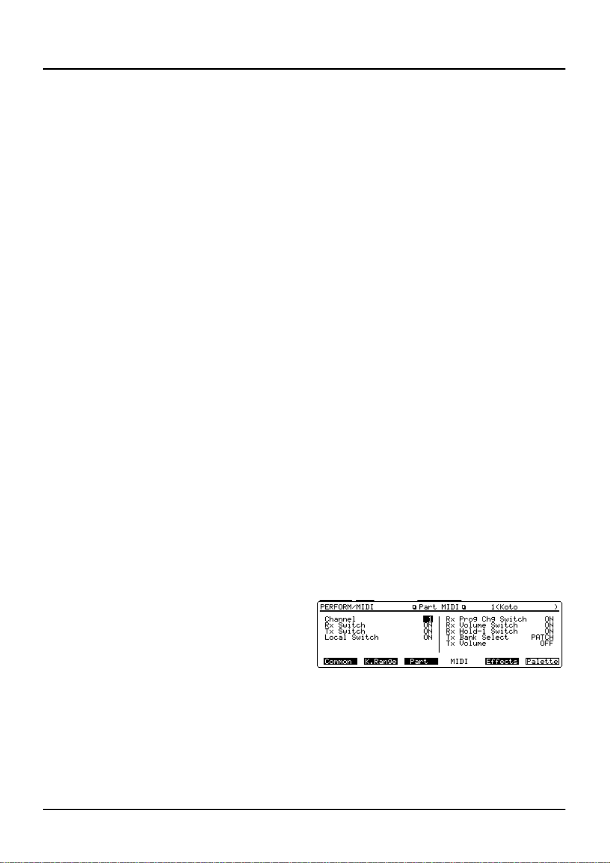
In the text, parameters are referred to as “Channel parameter
(PERFORM/MIDI/Part MIDI) for instance. This means the
Channel parameter is found in the MIDI Group’s Part MIDI
display in Performance mode. Display screens will also be
referred to in a similar manner; e.g., “Part MIDI display
(PERFORM/MIDI).”
For parameters located in the same display, descriptions in
parentheses () are omitted; e.g., “Rx Switch parameter.”
Display screens
Display screen figures in this manual may sometimes differ
from factory settings.
Mode
Display nameDisplay group
7
Chapter outlines
Page 6

8
Important notes ..........................................................................................................................4
Features of the XP-80.................................................................................................................6
Chapter outlines .........................................................................................................................7
Contents......................................................................................................................................8
Names and functions of buttons and controls......................................................................14
Chapter 1. An overview of the XP-80 ................................................................18
XP-80 configuration..................................................................................................................18
Basic configuration.....................................................................................................................18
Classification of XP-80 sound types...........................................................................................18
Basic operation.........................................................................................................................20
Switching modes ........................................................................................................................20
Switching displays......................................................................................................................20
Moving the cursor.......................................................................................................................23
Modifying a value........................................................................................................................23
Assigning a name.......................................................................................................................24
Chapter 2. Playing...............................................................................................26
Playing in Patch mode .............................................................................................................26
Selecting a Patch........................................................................................................................26
Displaying a Patch list ................................................................................................................27
Making a Patch sound thick or thin (turning a Tone on/off)........................................................27
Playing single notes (Solo).........................................................................................................28
Creating smooth pitch changes (Portamento)............................................................................28
Quick sound character changes (Sound Palette).......................................................................28
Playing in Performance mode .................................................................................................29
Selecting a Performance............................................................................................................29
Displaying a Performance’s Sound List window.........................................................................29
Playing fatter and richer sounds by combining Patches (Layer) ................................................30
Splitting the keyboard to play separate Patches in different sections (Split)..............................30
Playing along with a song playback (XP-80 used as a multitimbral sound source)....................31
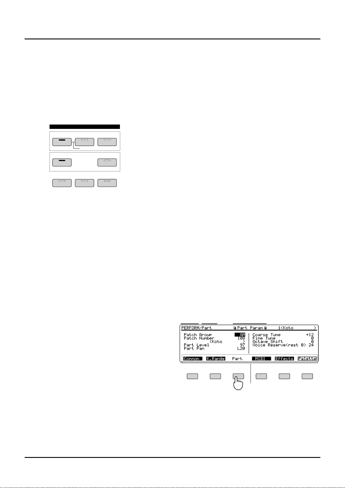
Assigning a different Patch to a Part..........................................................................................32
Quick sound character changes (Sound Palette).......................................................................32
Playing in Rhythm Set mode...................................................................................................33
Selecting a Rhythm Set..............................................................................................................33
Displaying Sound List window of a Rhythm Set.........................................................................34
Playing percussion instruments..................................................................................................34
Playing an arpeggio..................................................................................................................35
Playing an arpeggio over a preset keyboard area......................................................................36
Holding an arpeggio ...................................................................................................................36
Simulating a guitar cutting technique..........................................................................................36
Playing an arpeggio from an external MIDI device.....................................................................36
Creating an arpeggio pattern......................................................................................................36
Recording an arpeggio...............................................................................................................37
Convenient functions for performance...................................................................................37
Transposing the keyboard in octave units (Octave Shift)...........................................................37
Transposing the keyboard in semitone steps (Transpose).........................................................38
If ‘stuck’ notes occur or a note does not sound (Panic)..............................................................38
Contents
Page 7

9
1
2
3
4
5
6
7
8
9
10
11
12
Chapter 3. Creating your own sounds..............................................................39
Regarding effects .....................................................................................................................39
How effects units work in different modes..................................................................................39
Turning effects on/off..................................................................................................................40
Sound editing procedures.......................................................................................................40
Editing a Patch ...........................................................................................................................40
Editing a Performance................................................................................................................43
Editing a Rhythm Set..................................................................................................................44
Keeping edited sound .............................................................................................................45
Memory and data storage...........................................................................................................45
Storing a sound you modify into user memory...........................................................................46
Functions of Patch parameters...............................................................................................46
Settings common to the entire Patch (Common)........................................................................46
Modifying waveform and pitch (WG) ..........................................................................................51
Modifying the brightness of sound with a filter (TVF) .................................................................54
Changing the sound’s volume (TVA) .........................................................................................55
Modulating sounds-Adding Vibrato, Tremolo, etc./Using controllers to Change
how sounds are played (LFO&Ctl) .............................................................................................57
Setting effects for a Patch (Effects)............................................................................................60
Functions of Performance parameters...................................................................................65
Settings common to the entire Performance (Common)............................................................65
Setting the keyboard range (K.Range).......................................................................................66
Making settings for each Part (Part)...........................................................................................66
Making MIDI settings for a Part (MIDI).......................................................................................67
Setting effects for a Performance (Effects).................................................................................68
Confirming MIDI information for each Part (Info) .......................................................................69
Functions of Rhythm Set parameters.....................................................................................70
Naming a Rhythm Set (Common) ..............................................................................................70
Modifying waveform and pitch of a Rhythm Tone (Key WG)......................................................70
Changing the tone (filter) of a Rhythm Tone (Key TVF).............................................................71
Changing the volume of a Rhythm Tone (Key TVA) ..................................................................72
Controlling how a Rhythm Tone will sound with controllers (Key Ctl) ........................................72
Setting effects for a Rhythm Tone (Effects)................................................................................73
EFX effect types (EFX Parameter)...........................................................................................74
XP-80 operating environment setup (System parameters and their functions) .................88
Setups and keyboard settings (Setup) .......................................................................................88
Adjusting tuning (Tune) ..............................................................................................................89
MIDI settings (MIDI)....................................................................................................................90
Assigning sliders, pedals and other controllers (Control)...........................................................92
Arpeggio settings (Arpeg)...........................................................................................................93
Confirming the XP-80’s current conditions (Info)........................................................................95
Page 8

10
Chapter 4. Playing back and recording a song................................................96
About the sequencer................................................................................................................96
Songs .........................................................................................................................................96
Track configuration.....................................................................................................................96
Position for storing a song..........................................................................................................96
Playing back a song.................................................................................................................97
Playing back a song directly from disk (Quick Play)...................................................................98
Fast-forwarding or ‘rewinding’ a song.........................................................................................98
Resuming playback from the middle of a song (MIDI Update) ..................................................99
Programming songs for playback...............................................................................................99
Changing the Part to be played from the keyboard....................................................................99
Changing the instrument sounds for song playback...................................................................99
Silencing specific instruments 1 (Muting Phrase tracks)..........................................................100
Silencing specific instruments 2 (Turning the Receive channel off).........................................100
Playing back a song with a tempo change...............................................................................100
Playing back a song with a constant tempo (Muting the Tempo track)....................................101
Playing back a Pattern..............................................................................................................101
Playing back a song created in the S-MRC format ..................................................................102
Repeatedly playing back a song (Loop Play)...........................................................................102
Changing sound character during playback.............................................................................102
Adjusting volume balance between Parts.................................................................................103
Adjusting panning of each Part.................................................................................................103
Before you start to record......................................................................................................104
Recording process....................................................................................................................104
How Phrase tracks, Parts and MIDI channels interact.............................................................104
Recording methods ..................................................................................................................104
Recording destinations of performance data............................................................................104
Selecting instrument sounds ....................................................................................................105
Erasing the song from internal memory....................................................................................105
Setting the time signature.........................................................................................................105
Recording as you play (Realtime recording)........................................................................106
Settings for realtime recording..................................................................................................106
Performing realtime recording..................................................................................................108
Recording specific data only (Recording Select)......................................................................109
Changing the Phrase track during recording (Non-stop Loop Recording)................................109
Checking instrument sounds or phrases during recording (Rehearsal) ...................................109
Deleting unwanted data during recording (Realtime Erase).....................................................110
Recording tempo changes........................................................................................................110
Changing instrument during recording .....................................................................................110
Modifying parameter values of each Part during recording......................................................111
Checking MIDI messages received by each Part during recording..........................................111
Changing the sound character of each Part during recording..................................................111
Recording volume balance between Parts...............................................................................112
Panning Parts during recording ...............................................................................................112
Canceling recording (Undo)......................................................................................................112
Inputting data step by step (Step recording).......................................................................113
Inputting notes and rests..........................................................................................................113
Assigning a Pattern to a Phrase track......................................................................................114
Deleting recording (Undo) ........................................................................................................115
Saving the recorded song to disk.........................................................................................115
Saving sound data along with a song.......................................................................................115
Saving only a song...................................................................................................................116
Saving a song in the Standard MIDI File format.......................................................................116
Page 9

Chapter 5. Editing a song.................................................................................117
Sequencer operating environment setup.............................................................................117
Settings for an entire song....................................................................................................118
Naming a song (Song Name)...................................................................................................118
Naming a Pattern (Pattern Name)............................................................................................118
Monitoring Phrase track data and settings...............................................................................119
Locate function.........................................................................................................................119
Setting loop...............................................................................................................................120
Editing performance data over the specified range (Track Edit)........................................121
About Track Edit.......................................................................................................................121
Setting the editing area.............................................................................................................122
Erasing data input mistakes — 1 Erase ...................................................................................123
Deleting unwanted data portions — 2 Delete...........................................................................124
Copying a phrase — 3 Copy ....................................................................................................124
Inserting blank measures — 4 Insert Meas (Insert measure)...................................................126
Transposing the pitch — 5 Transpose......................................................................................126
Modifying velocity — 6 Chg Velocity (Change velocity) ...........................................................127
Changing MIDI channel — 7 Chg Channel (Change MIDI channel)........................................128
Changing note length — 8 Chg Gate Time (Change gate time)...............................................129
Combining two Phrase Tracks/Patterns into one — 9 Merge...................................................130
Extracting and moving a part of performance data — 10 Extract.............................................131
Shifting performance data backward or forward — 11 Shift Clock ..........................................132
Thinning out performance data — 12 Data Thin ......................................................................133
Exchanging Phrase tracks/Patterns — 13 Exchange...............................................................134
Adjusting the song playback time — 14 Time Fit ....................................................................134
Deleting blank measures — 15 Truncate.................................................................................135
Aligning a song’s timing (Quantize) .....................................................................................136
About quantizing.......................................................................................................................136
Grid quantize............................................................................................................................137
Shuffle quantize........................................................................................................................138
Groove quantize.......................................................................................................................139
Editing performance data one at a time (Microscope Edit)................................................144
Viewing the Microscope display ...............................................................................................144
Viewing only specific performance data...................................................................................146
Modifying performance data recorded in a Phrase track/Pattern.............................................146
Modifying tempo change recorded on the Tempo track...........................................................147
Modifying data recorded on the Beat track...............................................................................147
Setting the time signature of a Pattern.....................................................................................147
Inserting new performance data into a Phrase track/Pattern ...................................................147
Changing the tempo during a song ..........................................................................................148
Changing the time signature during a song..............................................................................148
Erasing performance data........................................................................................................149
Moving performance data.........................................................................................................149
Copying performance data.......................................................................................................149
Chapter 6. Realtime Phrase Sequencing (RPS).............................................150
Getting ready to use RPS ......................................................................................................150
RPS parameters.......................................................................................................................150
Playing using RPS..................................................................................................................151
Playing a Pattern from a external MIDI keyboard using RPS...................................................151
Recording performance using RPS..........................................................................................151
11
Page 10

12
Chapter 7. Playing songs in sequence (Chain Play)......................................153
Getting ready for Chain Play .................................................................................................153
Saving a chain to disk............................................................................................................154
Chain play ...............................................................................................................................154
Chapter 8. XP-80 memory settings (Utility mode)..........................................155
About Utility mode..................................................................................................................155
Storing sound data in user memory — 1 Write ...................................................................156
Performance write ....................................................................................................................156
Patch write................................................................................................................................156
Rhythm Set write......................................................................................................................156
Copying sound source settings — 2 Copy ..........................................................................157
Performance copy ....................................................................................................................157
Patch copy................................................................................................................................158
Rhythm Set copy......................................................................................................................159
Initializing sound source settings — 3 Initialize..................................................................160
Performance initialize...............................................................................................................160
Patch initialize...........................................................................................................................160
Rhythm Set initialize.................................................................................................................160
Transmitting sound settings — 4 Data Transfer..................................................................161
Transmitting data to an external MIDI device...........................................................................161
Transmitting data to the internal song......................................................................................161
Transmitting data to user memory............................................................................................162
Preventing user memory writing operation — 5 Protect (User memory protect).............164
Erasing the internal song — 6 Song Init (Song initialize) ..................................................164
Checking internal memory consumption — 7 Memory Info (Internal memory information)
..164
Recalling factory default settings — 8 Factory (Factory preset) .......................................165
Chapter 9. Disk-related functions (Disk mode)..............................................166
About Disk mode....................................................................................................................166
Loading a file from disk into the XP-80 — 1 Load...............................................................167
Saving data to disk — 2 Save................................................................................................168
Formatting the disk for the XP-80 — 3 Format ....................................................................169
Making a copy of a disk — 4 Backup....................................................................................170
Checking files recorded on disk — 5 Verify.........................................................................170
Changing the name of disk — 6 Volume (Change volume label).......................................170
Deleting unwanted files — 7 Delete (Delete file)..................................................................171
Renaming a file — 8 Rename ................................................................................................171
Checking the contents of disk — 9 Info (Disk information)................................................172
Chapter 10. Using the XP-80 as the GM sound source.................................173
Entering GM mode..................................................................................................................173
Initializing the sound source for GM System basic settings .....................................................173
Playing back a GM score..........................................................................................................173
Modifying GM mode settings ................................................................................................174
Setting a Part (Part)..................................................................................................................174
Making effects settings in GM mode (Effects)..........................................................................174
Confirming MIDI information of each Part (Info).......................................................................175
Page 11

Convenient functions in GM mode (GM Utility)...................................................................176
Copying effects settings — 2 Copy (GM Copy)........................................................................176
Initializing GM mode — 3 Initialize (GM Initialize)....................................................................176
Transmitting GM mode settings — 4 Data Transfer (GM Data Transfer).................................177
Chapter 11. Getting the full potential of the XP-80........................................178
Techniques for using Patches...............................................................................................178
Reinforcing filter characteristics................................................................................................178
Making the up-beat note sound at the same time you play a down-beat note ........................178
Holding a note with modulation retained ..................................................................................178
Syncing the LFO cycle to sequencer tempo.............................................................................178
Modifying EFX to match the tempo of a song...........................................................................178
Using a pedal switch to modify the rotary speed of the Rotary effect ......................................179
Playing breakbeats at a song’s tempo......................................................................................179
Using the C1 slider to pan sounds in real time.........................................................................179
Using the XP-80 to play live...................................................................................................179
Changing multiple sounds of an external MIDI device simultaneously.....................................179
Changing sounds with a pedal switch ......................................................................................180
Using a pedal switch to start and stop playback ......................................................................180
Matching the song’s playback tempo with the tempo of the band that’s playing......................180
Playing a drum referring to a XP-80 click.................................................................................180
Song making techniques.......................................................................................................180
Recording a song with a consistent volume level regardless of keyboard playing dynamics...180
Having a song fade in or out.....................................................................................................180
Changing a sound during a song..............................................................................................181
Avoiding sound dropouts in a song ..........................................................................................182
Using external MIDI devices..................................................................................................182
Using the XP-80 to change the sound on an external MIDI device..........................................182
Using the XP-80 to control external MIDI devices....................................................................182
Playing the XP-80 sound source from an external MIDI device...............................................183
Synchronization with external MIDI devices........................................................................183
Syncing an external sequencer to the XP-80’s sequencer.......................................................183
Syncing the XP-80’s sequencer to an external sequencer.......................................................183
Recording a song from an external sequencer into the XP-80’s sequencer ............................183
Synchronizing to the VS-880 Hard Disk Recorder...............................................................184
Getting ready to sync to the VS-880.........................................................................................184
Playing back Song files ..........................................................................................................185
Recording on the VS-880.........................................................................................................185
Recording on the XP-80 ..........................................................................................................186
Chapter 12. Supplementary material...............................................................187
Troubleshooting......................................................................................................................187
Error messages ......................................................................................................................188
Parameter list..........................................................................................................................190
Factory preset settings..........................................................................................................206
Arpeggio style list ..................................................................................................................213
MIDI implementation ..............................................................................................................214
Specifications....................................................................................................231
Quick reference of displays.............................................................................232
Index...................................................................................................................241
13
Page 12
14
❚
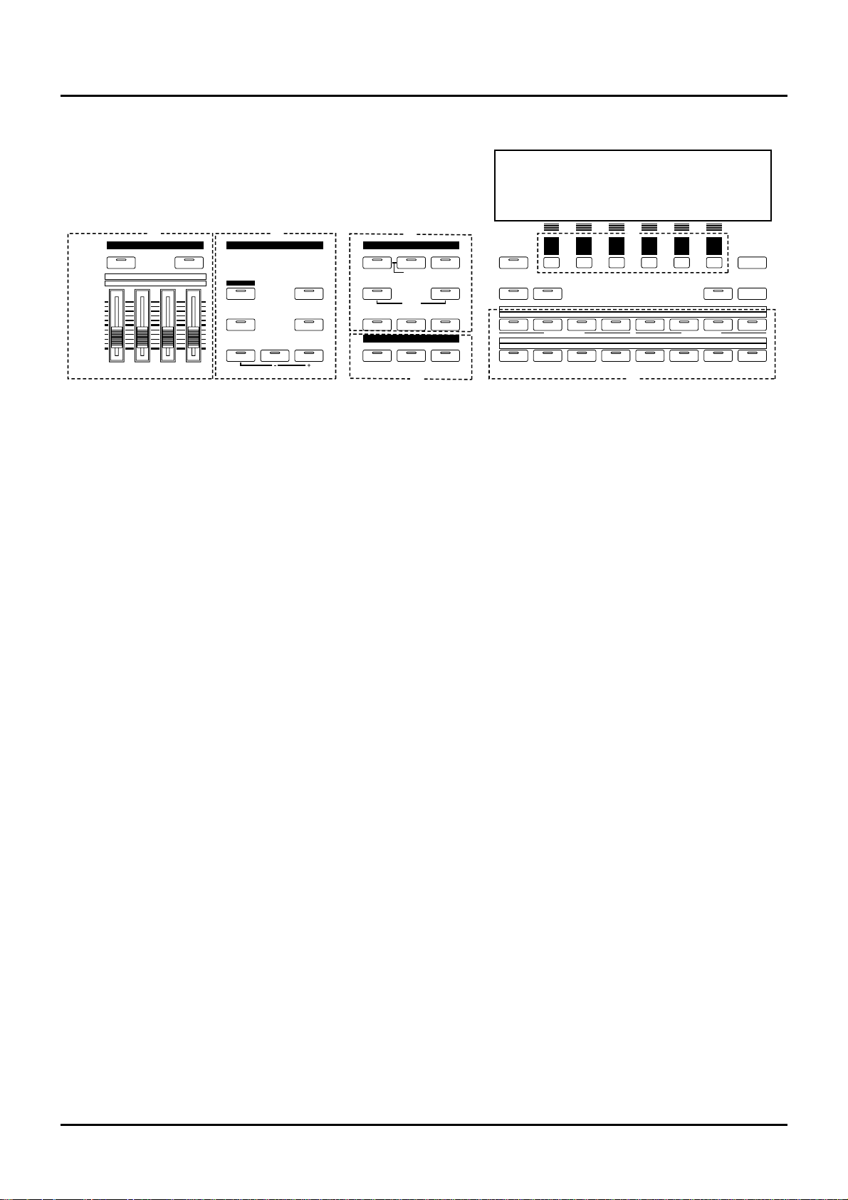
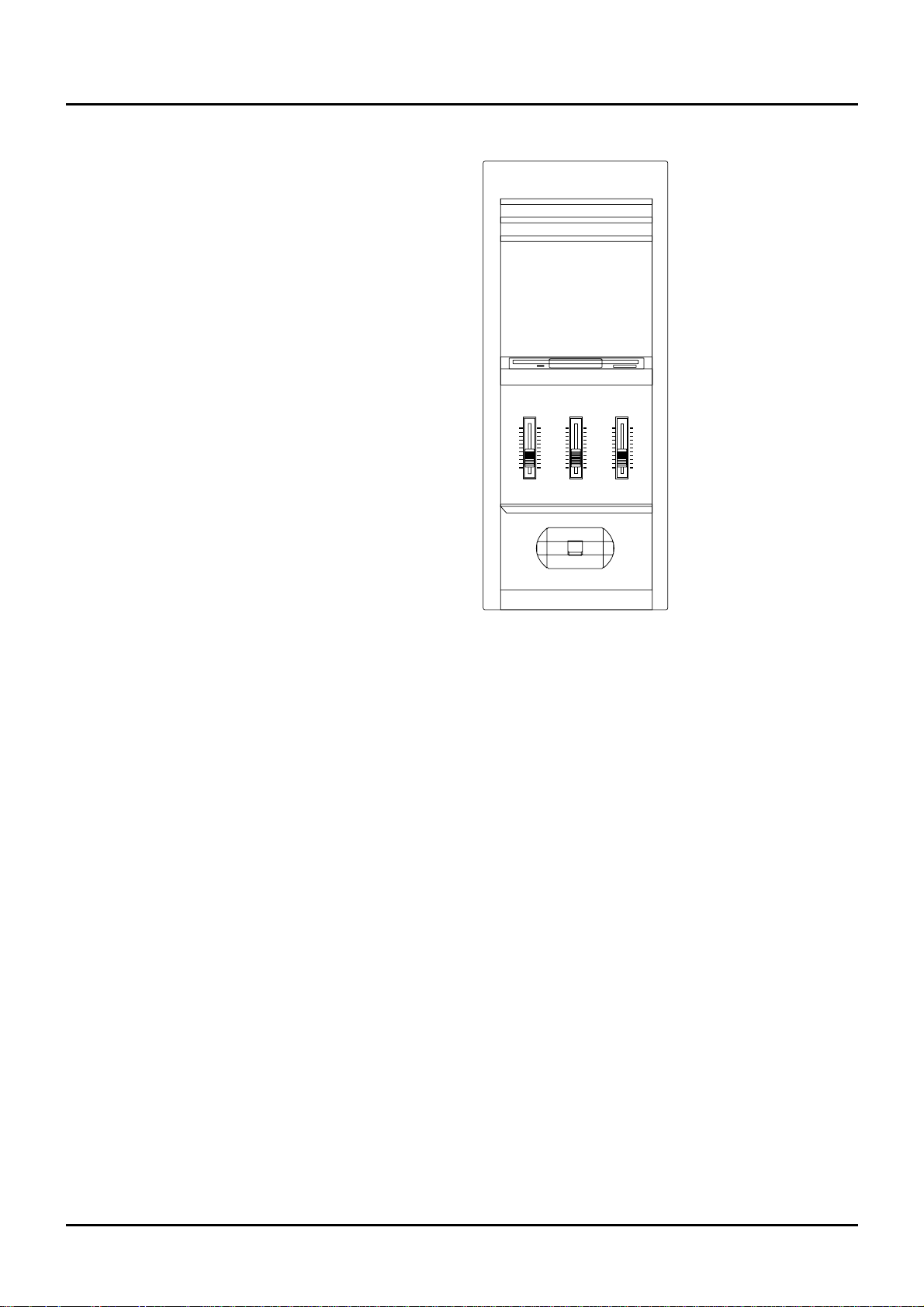
Front panel
A. SOUND PALETTE section
Use the four sliders to modify sounds in real time.
[FILTER/ENV]
Press this button ON when modifying filter and/or
envelope settings in real time using the four sliders
(p.28, 32).
[LEVEL]
Press this button ON when adjusting volume balance
in real time using the four sliders (p.28, 32).
B. KEY EFFECTS section
The buttons in this section allow you to assign various
functions to the keys of the XP-80’s keyboard.
[RPS]
Switches RPS on/off (p.151).
[ARPEGGIO]
Switches Arpeggiator on/off (p.35).
[PORTAMENTO]
Switches Portamento on/off (p.28).
[SOLO]
Specifies playing a single note at a time (p.28).
[TRANSPOSE]
Specifies transposing the keyboard in semitone steps
(p.38).
[+OCT], [-OCT]
These buttons adjust the pitch of the keyboard in
octave steps (p.37).
Pressing either of these buttons while holding down
[TRANSPOSE] allows you to set the desired amount
of transposition (p.38).
C. MODE section
The buttons in this section select modes. The button
indicator of the selected mode will light (p.20).
D. EFFECTS section
The buttons in this section turn their respective internal effects (EFX, Chorus and Reverb) on/off.
[EFX]
Switches the multiple effects unit (EFX) on/off (p.40).
[CHORUS]
Switches Chorus on/off (p.40).
[REVERB]
Switches Reverb on/off (p.40).
E. [F1]–[F6] (Function buttons)
Each of these buttons corresponds to a function indicated at the display bottom. The functions of these
buttons change depending on the selected mode or the
current display (p.20).
F.
[LOCAL/TX/RX]
This button opens the LOCAL/TX/RX window for
switching Local, Transmit and Receive switches
on/off (p.30).
[EXIT] / [PANIC]
The function of this button changes depending on
whether you hold down [SHIFT] or not.
EXIT: Press this button to return to the Play display of
a mode (p.21), or when you want to cancel the current
operation.
PANIC: If notes stick or do not sound, hold down
[SHIFT] and press this (p.38).
GM PANIC
F1
EFFECTS
MODESOUND PSOUND PALEALETTETE
KEY EFFECTS
F2 F3 F4 F5 F6
EXIT
CHAIN PLAYSEQUENCER
RHYTHMPATCH
UNDO/ REDO
l
LOCATE
+ OCT- OCTTRANSPOSE
PORTAMENTO SOLO
ARPEGGIO
REVERBCHORUSEFX
SOUND LIST
12345678
9 10111213141516
12345678
1
TRACK/ PART
TRACK/ PART
BANK
NUMBER
2345678
LOCAL/ TX/ RX
PERFORMFILTER/ ENV
l
LEVEL
UTILITYSYSTEM DISK
RPS
FILTER/ENV
l
LEVEL
1
DECAYRESO. ATTACKCUTOFF
234
PART
TEMPO/ BEAT PA TTERN
TONE SWITCH
TONE SELECT
DEMO
A B
C
D
G
E
K
F
F
a/b/c/d
Names and functions of buttons and controls
Page 13
[SOUND LIST] / [TEMPO/BEAT]
The function of this button changes depending on the
selected mode.
SOUND LIST: Opens the Sound List window when a
sound source mode display is up (p.27, 29, 34).
TEMPO/BEAT: Press this button for selecting a tempo
track or beat track when a Sequencer mode display is
up. If you have temporarily modified the tempo and
wish to play back the song with its initial tempo, press
it while holding down [SHIFT] (p.100).
[a/b/c/d] / [PATTERN]
The function of this button changes depending on the
mode on display.
a/b/c/d: Select a subgroup (a/b/c/d) when selecting
a Patch/Performance/Rhythm Set using the
Bank/Number method (p.26, 29, 33).
PATTERN: Select a Pattern when a Sequencer mode
display is up.
[LOCATE]
This button opens the Locate window to specify and
move the locate position (p.119).
[UNDO/REDO]
Press this button to restore a modified value to its previous (pre-modified) state, or when cancelling recording or a currently executing operation. Pressing this
button again will restart the recording/operation
(p.24).
G.
BANK [1]–[8], NUMBER [1]–[8] / TRACK / PART
[1]–[16]
The functions of these buttons change depending on
the display which is showing.
Play display of a sound source mode: Selects a
Patch/Performance/Rhythm Set with the Bank
/Number method. Use BANK [1]–[8] buttons to select
a bank and NUMBER [1]–[8] buttons to select a number (p.26, 29, 33).
Performance edit display: Use TRACK/PART [1]–[16]
buttons to select the Part to be modified (p.43).
Patch edit display: TRACK/PART [1]–[4] buttons
(TONE SWITCH) are used to switch a Tone on/off
(p.27). Use TRACK/PART [5]–[8] buttons (TONE
SELECT) to select the Tone to be modified (p.40).
Rhythm Set edit display: Use TRACK/PART [5]–[8]
buttons (TONE SELECT) to select the note of the keyboard to be modified (p.44).
Sequencer mode: Use TRACK/PART [1]–[16] buttons
to select a phrase track or Part (p.108). During song
playback/recording, these buttons can be used to
switch between the Play and Mute of a phrase track
(p.100).
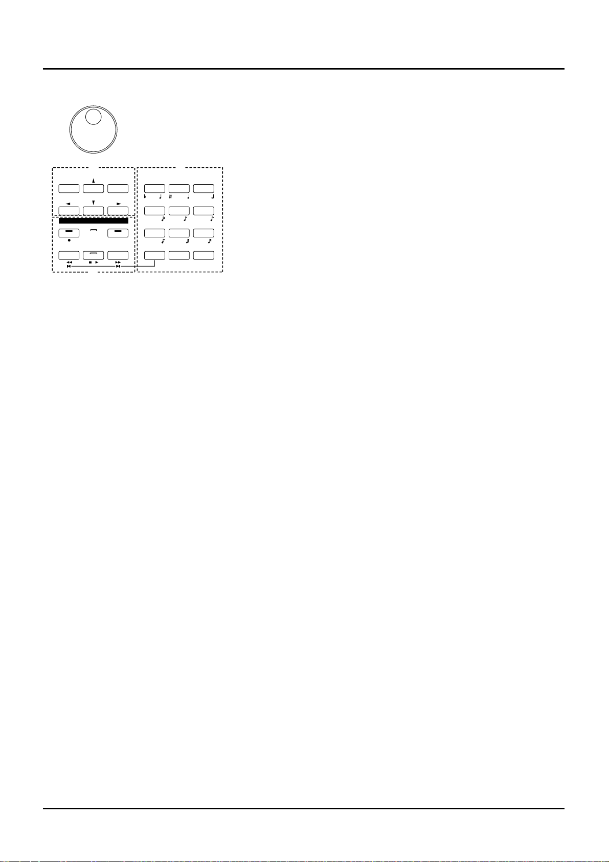
H.
[l ], [r ], [u ], [d ] (Cursor buttons)
Move the cursor (black box) with these (p.23).
[INC], [DEC]
Use these buttons to modify values. If you keep on
holding down one button and pressing the other, the
value change accelerates. If you press one of these buttons while holding down [SHIFT], the value will
change in bigger increments (p.23).
I. SEQUENCER section
The buttons in this section are used for playback and
recording of the XP-80’s sequencer.
[REC]
Press this to begin recording (p.106, 113).
BEAT indicator
This blinks in sync with the tempo and beat of the
song.
[LOOP]
Press this to turn Loop Play and Loop Recording
on/off (p.102).
[BWD]
Press this to “rewind” a song. Pressing this button
while holding down [SHIFT] moves you right back to
the beginning of the song. If you hold down this button as you press [FWD], the song will “rewind” faster
(p.98).
[STOP/PLAY]
Press this button to start or stop playback of the song.
E F
G
B
C
A DIGIT HOLD
l
D
3
3
3
+ -
SEQUENCER
YZ!VWXSTU
PQRMNOJKL
GHIDEFABC
ENTERSHIFT SPACE
REC BEAT
BWD FWDSTOP/ PLAY
l
I
LOOP
DEC INC
VALUE
0
123
456
789
L
H
I
J
15
Page 14
16
[FWD]
Use this button to fast-forward the song. Pressing this
button while holding down [SHIFT] moves you to the
end of the song. If you hold down this button as you
press [BWD], the song will fast-forward faster (p.98).
J.
[0]–[9] (Numeric keys)
Use these to set a value. They can be used to enter
numeric values as well as alphabetical characters and
notes (p.23).
[SHIFT]
This is used in combination with other buttons. Some
buttons on the front panel include grey-printed characters. They indicate the button’s function when
[SHIFT] is held down.
[ENTER] / [DIGIT HOLD]
The function of this button changes depending on
whether [SHIFT] is being held down or not.
ENTER: Use this button to finalize a value (p.23).
DIGIT HOLD: Press this button while holding down
[SHIFT] to turn the Digit Hold function on/off. With
the Digit Hold on, the 100’s place and 10’s place will
be fixed and only the 1’s place will change. This means
that you can select Patches simply by pressing the
numeric key for the 1’s place, without having to press
[ENTER] (p.27).
K.
Display
Shows various information for the currently selected
function or operation.
L.
VALUE dial
This dial is used to modify values. If you hold down
[SHIFT] as you turn the VALUE dial, the value will
change in greater increments (p.23).
❚
Side panel
VOLUME slider
This slider adjusts the overall output level from the
rear panel OUTPUT and PHONES jacks.
C1 slider, C2 slider
Various parameters or functions can be assigned to
these sliders, so you can control the sound source section as you play (p.92).
Pitch bend / modulation lever
This allows you to control pitch bend or apply vibrato.
Depending on the settings, other specified parameters
can also be controlled.
Floppy disk drive
3.5" 2DD/2HD floppy disks can be used. Press the
eject switch located at the lower right of the disk drive
to remove a disk.
VOLUME C2C 1
Page 15
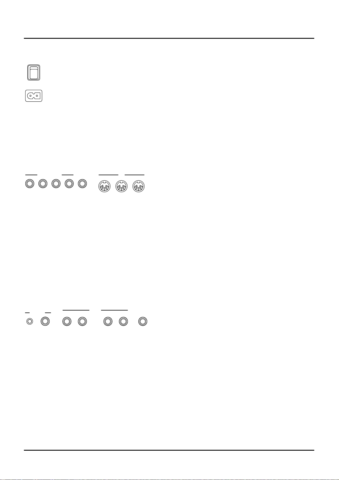
❚
Rear panel
Power switch
Press to turn the power on/off.
AC inlet
Connect the AC power cable (included) to this inlet.
✳
With units rated for 117V operation, the AC cable is
already connected to the unit.
CONTROL PEDAL 1–4 jacks
You can connect optional expression pedals to these
jacks. By assigning a desired function to a pedal, you
can use it to select or modify sound or perform various other control. You can also connect optional pedal
switches to sustain sound (p.92).
HOLD jack
An optional pedal switch can be connected to this jack
for use as a hold pedal.
MIDI connectors
These connectors can be connected to other MIDI
devices to receive and transmit MIDI messages.
CLICK OUT LEVEL knob
Adjusts the level of the click sound to be output to
external devices (p.180).
CLICK OUT OUTPUT jack
Connect a cable to this jack when sending clicks to
external devices (p.180).
OUTPUT DIRECT R jack, OUTPUT DIRECT L jack
These jacks output only the direct sound (no effects
applied) or EFX’d sound in stereo.
OUTPUT MIX R jack, OUTPUT MIX L jack
These jacks output the audio signal to the connected
mixer/amplifier system in stereo. For mono output,
use the L jack.
PHONES jack
An optional set of headphones can be connected to
this jack. Make sure that your headphones have an
impedance of 8–150 ohms.
AC
POWER
OUTTHRU
IN
MIDI
1
CONTROL PEDAL
324
HOLD
R
OUTPUTLEVEL
OUTPUT
CLICK OUT
L
R
PHONES
L
MIX
DIRECT
17 18 ❚
Page 16
XP-80 configuration
Basic configuration
The XP-80 consists of a sound source, a sequencer and controllers.
Sound source
The XP-80 sound source produces sound by responding to
commands in the form of MIDI messages received from its
controllers and sequencer. It will also produce sound by
responding to commands received from various external
devices it can be connected to.
Sequencer
The sequencer records various controller operations as MIDI
messages and transmits them to the sound source. MIDI
messages recorded on the sequencer can also be transmitted
from the MIDI OUT connector to allow the XP-80 to also
control external MIDI devices.
Controllers
Controllers include the keyboard, front panel sliders and
pedals which are connected to their respective rear panel
jacks. Adjusting these controllers enable you to produce or
modify sound.
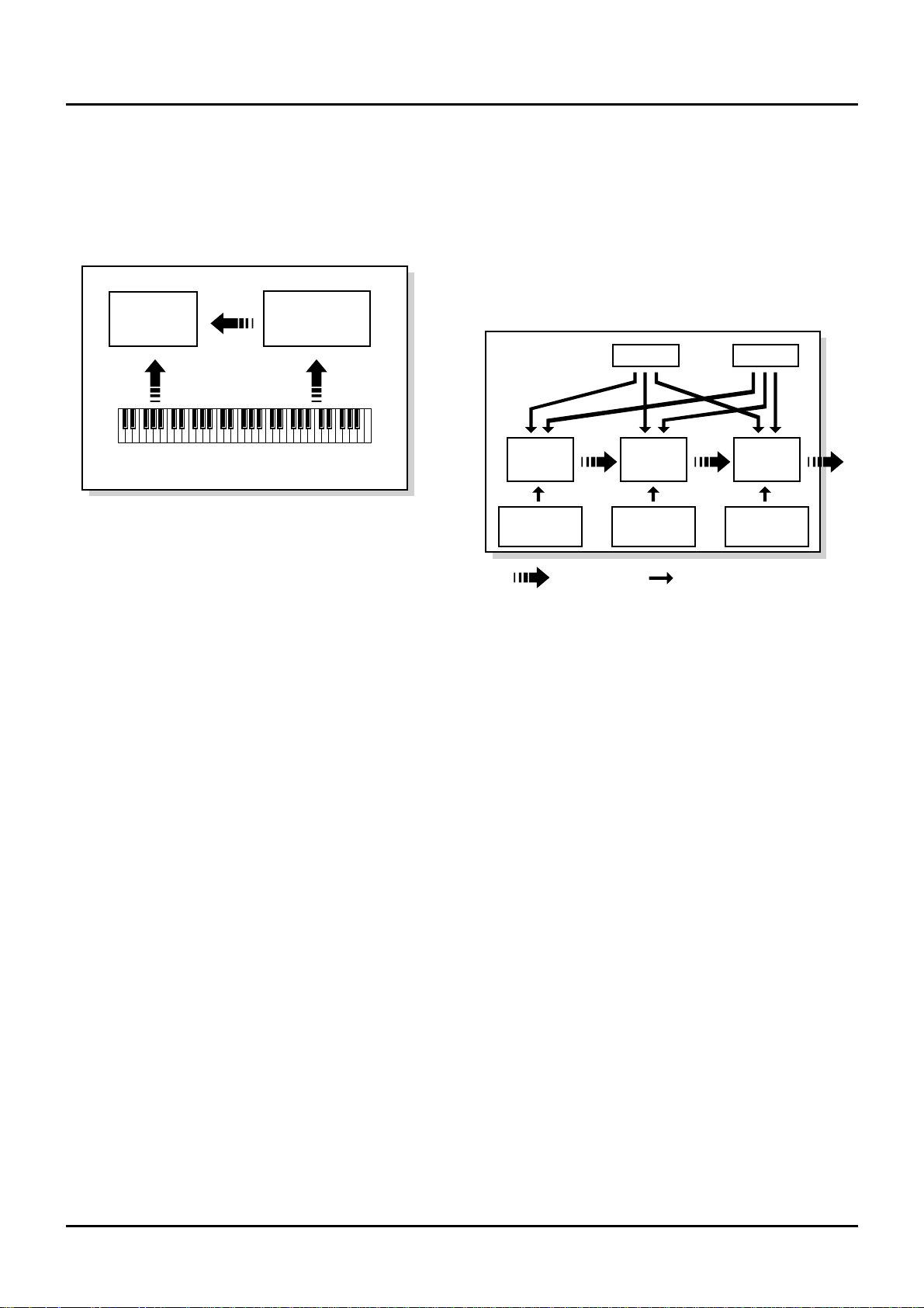
Classification of XP-80 sound types
XP-80 sounds are made up of the following types:
Tones
In the XP-80, the Tone is the smallest class of sound. Each
Tone consists of one sound. But when you play the XP-80
you will mostly play a Patch, which is made up of several
Tones. Tones therefore are the elements which collectively
form a Patch.
Tone configuration:
WG (Wave Generator)
Using the Wave Generator, you select a waveform and set its
pitch.
TVF (Time Variant Filter)
With the Time Variant Filter, you modify the waveform’s
frequency characteristics.
TVA (Time Variant Amplifier)
With the Time Variant Amplifier, you set volume level and
set the sound’s position in a stereo soundfield.
Envelope
You use Envelope to initiate changes to occur to a sound
over time. There are separate Envelopes for the WG (pitch),
TVF (filter) and TVA (volume). For example, to modify a
sound’s attack and decay time, you would use TVA
Envelope to adjust volume changes to the sound over time.
LFO (Low Frequency Oscillator)
Use the LFO to create cyclic changes (modulation) in a
sound. The XP-80 has two LFOs. Either one or both can be
applied to effect the WG (pitch), TVF (filter) and/or TVA
(volume). To illustrate this control’s action, you can apply an
LFO to modify the WG (pitch) to create vibrato. If the LFO is
used to modify the TVA (volume), you’ll get tremolo.
Controller section (controllers such as
keyboard, pitch bend lever, etc.)
Sound source
section
Playback
Sequencer
section
Play
Recording
WG
Pitch
Envelope
TVF
TVF
Envelope
TVA
Envelope
TVA
LFO 1 LFO 2
control signal
Tone
audio signal
Chapter 1. An overview of the XP-80
Chapter 1. An overview of the XP-80
Page 17
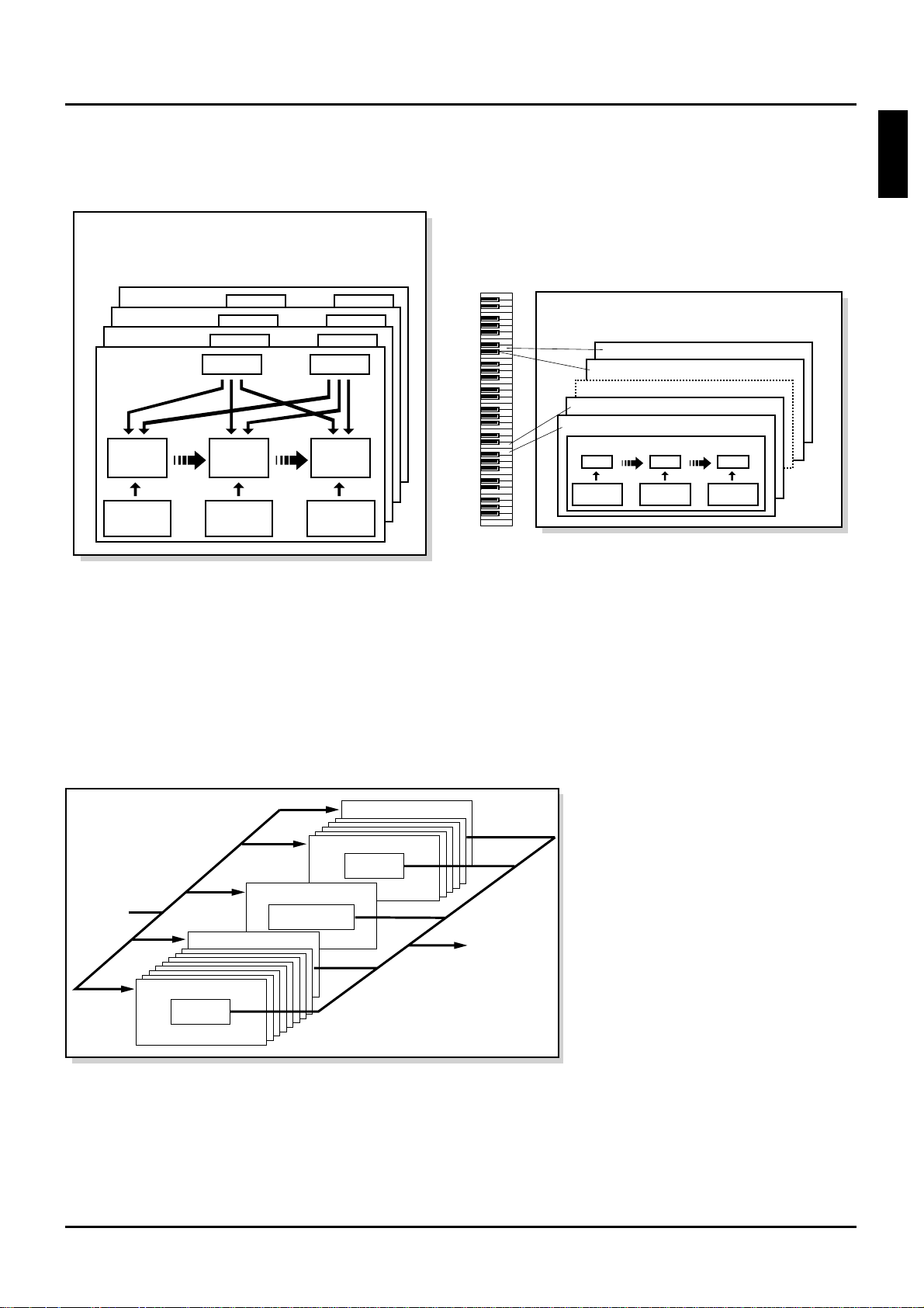
Patches
Patches are the basic sound configurations that you play
during a performance. Each Patch can be configured by combining up to four Tones. How the four Tones are combined
is determined on the Structure display (Patch/Common).
Performances
The next level in sound configuration. A single Performance
groups 15 Patches and one Rhythm Set so that they can be
combined to play ensembles or produce fabulously rich,
thick sounds. One Performance allows a single XP-80 to control up to 16 instrument sounds. Because the XP-80 sound
source can control multiple sounds (instruments) it is called
a ‘multitimbral sound source.’
Rhythm Sets
A Rhythm Set is a grouping of percussion instruments
(Rhythm Tones). Since percussion instruments generally do
not play melodies, there is no need for a percussion instrument sound to be able to play a scale on the keyboard. It is
however, more important that as many as possible percussion instruments be available to you at the same time.
Therefore, each key (Note number) of a Rhythm Set will produce a different percussion instrument.
Parts
When the XP-80 is used as a multitimbral sound source,
another sound configuration called a Part comes into play. A
Part contains a Patch or Rhythm Set. For multimbral applications, the Performance consists of 16 Parts. A specific Patch
can be assigned to each Part except Part 10 because Part 10 is
universally set as the Drum Part to which a Rhythm Set (discussed above) is assigned. In a multimbral context, it helps
to think of a Performance as an orchestra, each Part in it
being a musician, and the Patch or Rhythm Set that musician’s instrument.
For details regarding following items, please
refer to each corresponding page.
About the Memory (p. 45)
About the Effects (p. 39)
About the Sequencer (p. 96)
About the Song (p. 97)
Patch
Tone 4
Tone 3
Tone 2
Tone 1
WG
Pitch
Envelope
TVF
TVF
Envelope
TVA
Envelope
TVA
LFO 1 LFO 2
Note Number 98 (D7)
Note Number 97 (C#7)
Note Number 36 (C2)
Note Number 35 (B1)
Rhythm Tone (Percussion instrument sound)
Rhythm Set
WG
Pitch
Envelope
TVF
TVF
Envelope
TVA
Envelope
TVA
19
Chapter 1. An overview of the XP-80
2
3
4
5
6
7
8
9
10
11
12
1
Performance
Patch
Rhythm Set
Part 10 (MIDI receive ch.)
Part 11 (MIDI receive ch.)
Part 16 (MIDI receive ch.)
Patch
Part 1 (MIDI receive ch.)
Part 9 (MIDI receive ch.)
Sequencer,
Keyboard,
MIDI
Sound
Page 18
20
❚
Basic operation
Switching modes
The XP-80 has enough functions to bewilder you. To make it
easy to access the functions you need for specific applications, they’re grouped into modes. The mode you’ve selected determines how the sound source operates and what the
display shows. Select a Mode button. It will light and the
Play display of that selected mode will appear.
Sound source
Selecting Patch mode, Performance mode, Rhythm Set
mode, and GM mode will determine sound source operation. One mode always has to be selected.
Patch mode
In this mode, you can play an individual Patch from the keyboard or modify Patch settings. If you’re using an external
MIDI device to control the XP-80 in this mode, it will function as a single-patch sound source.
Performance mode
This mode makes the XP-80 function as a multitimbral
sound source, and Performance settings can be modified. If
you’re using an external MIDI device to control the XP-80 in
this mode, it will function as a multitimbral sound source.
To modify the settings of a Patch that’s assigned to a Part,
hold down [PERFORM] and press [PATCH]. Both button
indicators will light.
Rhythm Set mode
This is how you can play a Rhythm Set from the keyboard
and modify the Rhythm Set settings. In this mode, the keyboard will play the Rhythm Set, but the XP-80 continues to
function as a multitimbral sound source. So your effects settings of the currently selected Performance will be heard as
you play the Rhythm Set. Rhythm Sets are assigned to Part
10 of the Performance. If you’re using an external MIDI
device to control the XP-80 in this mode, it will still function
as a multitimbral sound source.
GM mode
This special mode makes the XP-80 function as a GM compatible sound source. You should select this mode when you
want to play back a GM score (music data created for GM
sound source).
To set GM mode, hold down [SHIFT] and press [PERFORM]. [PERFORM], [PATCH] and [RHYTHM] indicators
will not light.
Sequencer
Selecting Sequencer mode and Chain Play mode determines
how the sequencer will operate. One or the other of these
modes has to be selected for the sequencer to operate.
Sequencer mode
For recording, playing back and editing a song.
Chain Play mode
This allows you to select the order of how you want songs to
play back.
System mode
This mode is for determining global XP-80 settings such as
tuning, display contrast and how MIDI messages are
received.
✳ Some System mode parameters relate to an entire
Patch or an entire Performance. To set these parameters, press [SYSTEM] in the selected mode (Patch or
Performance).
Utility mode
The mode for saving and transmitting sound source settings.
✳ Some Utility mode parameters relate to an entire
Patch, Performance or Rhythm Set. To set these parameters, press [UTILITY] in the selected mode (Patch,
Performance or Rhythm Set).
Disk mode
For saving/loading data to/from the internal Floppy Disk.
Switching displays
Displays are grouped by mode. The bottom line displays
functions corresponding to [F1]–[F6] (function buttons).
Press the corresponding function button to call up the
desired display.
<Procedure>
❶ On the Play display of a selected mode (Menu display
will appear for Disk mode and Utility mode), press a
function button to choose a display group.
One of the selected group’s display pages will appear.
✳ The number of display pages varies by group.
PERFORM
SEQUENCER
SYSTEM
PATCH
CHAIN P LA Y
UTILITY
RHYTHM
PART
DISK
GM
Sound source
Sequencer
MODE
Mode
Display group
Display name
F1 F2 F3 F4 F5 F6
Function Name
Chapter 1. An overview of the XP-80
Page 19
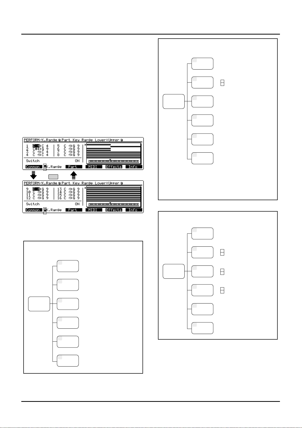
❷ Press the respective function button to call up a
desired display page.
When a function button is pressed, the highlighting of the
function name will disappear.
✳ When a function name is boxed, without being high-
lighted, it means that special functions like GoTo
another display page or an operation execute has been
assigned to that function button.
✳ Data may require two or more display pages if it can-
not all be shown on a single page. In that case, the
index mark indicating the total number of display
pages and the current display page appears to the left
of the function name. Repeat-pressing the function
button will allow you move to the other display pages.
✳ To return to the home Play display, press [EXIT].
Displays are divided into groups for each mode:
F2
Index mark
Play
Patch Mode
F3
TVF
F4
TVA
F5
LFO&Ctl
F6
Effects
F2
WG
F1
Common
Group Display
[F1] Common General
[F2] Common Control
[F3] Structure
[F4] Tone Key Range Lower:Upper
[F5]
Tone Vel Range Lower:Upper: Fade
[F1] Wave Param
[F2] Pitch
[F3] Pitch Envelope
[F1] TVF Param
[F2] TVF Envelope
[F1] TVA Param
[F2] TVA Envelope
[F1] LFO 1 Param
[F2] LFO 2 Param
[F3] Control Param
[F4] Control Switch
[F1] General
[F2] EFX Param
[F3] EFX Control
[F4] Chorus
[F5] Reverb
Play
Performance Mode
F3
Part
F4
MIDI
F5
Effects
F6
Info
F2
K.Range
F1
Common
Group Display
Common
Part Key Range Upper:Lower (Par1-8)
Part Key Rnage Upper:Lower (Part9-16)
Part Param
Part MIDI
[F1] General
[F2] EFX Param
[F3] EFX Control
[F4] Chorus
[F5] Reverb
--Part Infomation-[F1] Modulation
[F2] Breath
[F3] Foot
[F4] Volume
[F5] Pan
--Part Information-[F1] Expression
[F2] Hold-1
[F3] Pitch Bend
[F4] Channel After touch
[F5] Voices
--Part Information-[F1] System Control 1
[F2] System Control 2
Play
Rhythm Set Mode
F3
Key TVF
F4
Key TVA
F5
Key Ctl
F6
Effects
F2
Key WG
F1
Common
Group Display
Rhythm Set Name
Wave
Pitch Envelope
TVF Param
TVF Envelope
TVA Param
TVA Envelope
Control Param
[F1] General
[F2] EFX Param
[F3] EFX Control
[F4] Chorus
[F5] Reverb
21
Chapter 1. An overview of the XP-80
Page 20
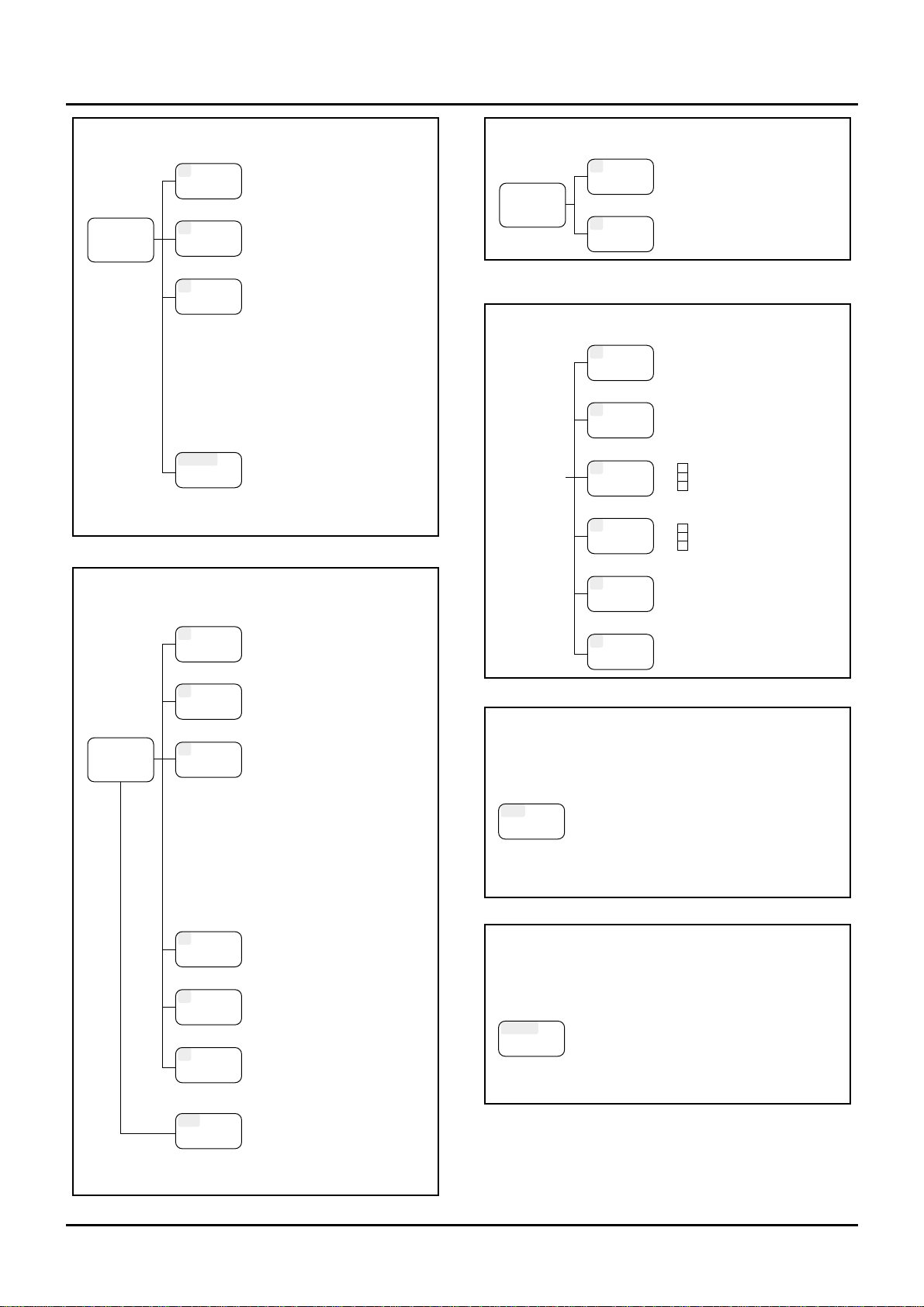
22
Play
GM Mode
F6
Info
UTILITY
UTILITY
F5
Effects
F4
Part
Group Display
Part Param
[F1] General
[F2] EFX Param
[F3] EFX Control
[F4] Chorus
[F5] Reverb
--Part Information-[F1] Modulation
[F2] Breath
[F3] Foot
[F4] Volume
[F5] Pan
--Part Information-[F1] Expression
[F2] Hold-1
[F3] Pitch Bend
[F4] Channel Aftertouch
[F5] Voices
Utility Menu
-----Menu 1----[F2] Copy
[F3] Initialize
[F4] Data Transfer
-----Menu 2----[F6] Song Initialize
[F7] Memory Info
-----Menu 3----[F8] Factory
Play
(Song/Pattern)
Sequencer Mode
F3
Trk Edit
F4
Micro
F5
Loop
F6
List
F2
Quantiz
F1
Setup
Group Display
REC
REC
[F1] Song Name
[F2] Pattern Name
[F3] Track Information
[F4] RPS Setup
[F6] SEQ System Setup
[F1] Grid Quantize
[F2] Shuffle Quantize
[F3] Groove Quantize
-----Menu 1----[F1] Erase
[F2] Delete
[F3] Copy
[F4] Insert Meas
[F5] Transpose
-----Menu 2----[F1] Change Velocity
[F2] Change Channel
[F3] Change Gate Time
[F4] Merge
[F5] Extract
-----Menu 3----[F1] Shift Clock
[F2] Data Thin
[F3] Exchange
[F4] Time Fit
[F5] Truncate
[F1] Create Event
[F3] Move Event
[F6] View Select
[REC]Step Recording
Loop Window
Song List Window
[F1] Part Palette
[F2] Part Information
[F3] Rec Filter Window
[F4] Auto Punch I/O Window
[F5] Loop Window
[F6] Rec Quantize Window
[
STOP
/PLAY] Recording Realtime
Rec Stand-by
Play
Chain Play Mode
F6
List
F5
Save
Group Display
Save
Chain File List Window
System Mode
F3
MIDI
F4
Control
F5
Arpeg
F6
Info
F2
Tune
F1
Setup
Group Display
Setup
Tune
MIDI Param 1
MIDI Param 2
Bank Select Group
Control Assign
Pedal Assign
Control Source
Arpeggio
System Information
Disk Mode
DISK
DISK
Display
Disk Menu
-----Menu 1----[F1] Load
[F2] Save
[F3] Format
[F4] Backup
[F5] Verify
-----Menu 2----[F1] Volume
[F2] Delete
[F3] Rename
-----Menu 3----[F1] Disk Information
Utility Mode
UTILITY
UTILITY
Display
Utility Menu
-----Menu 1----[F1] Write (Patch/Perform/Rhythm)
[F2] Copy (Patch/Perform/Rhythm)
[F3] Initialize (Patch/Perform/Rhythm)
[F4] Data Transfer (to MIDI/to Seq/to User)
[F5] User Memory Protect
-----Menu 2----[F1] Song Initialize
[F2] Internal Memory Information
-----Menu 3----[F1] Factory Preset
Chapter 1. An overview of the XP-80
Page 21
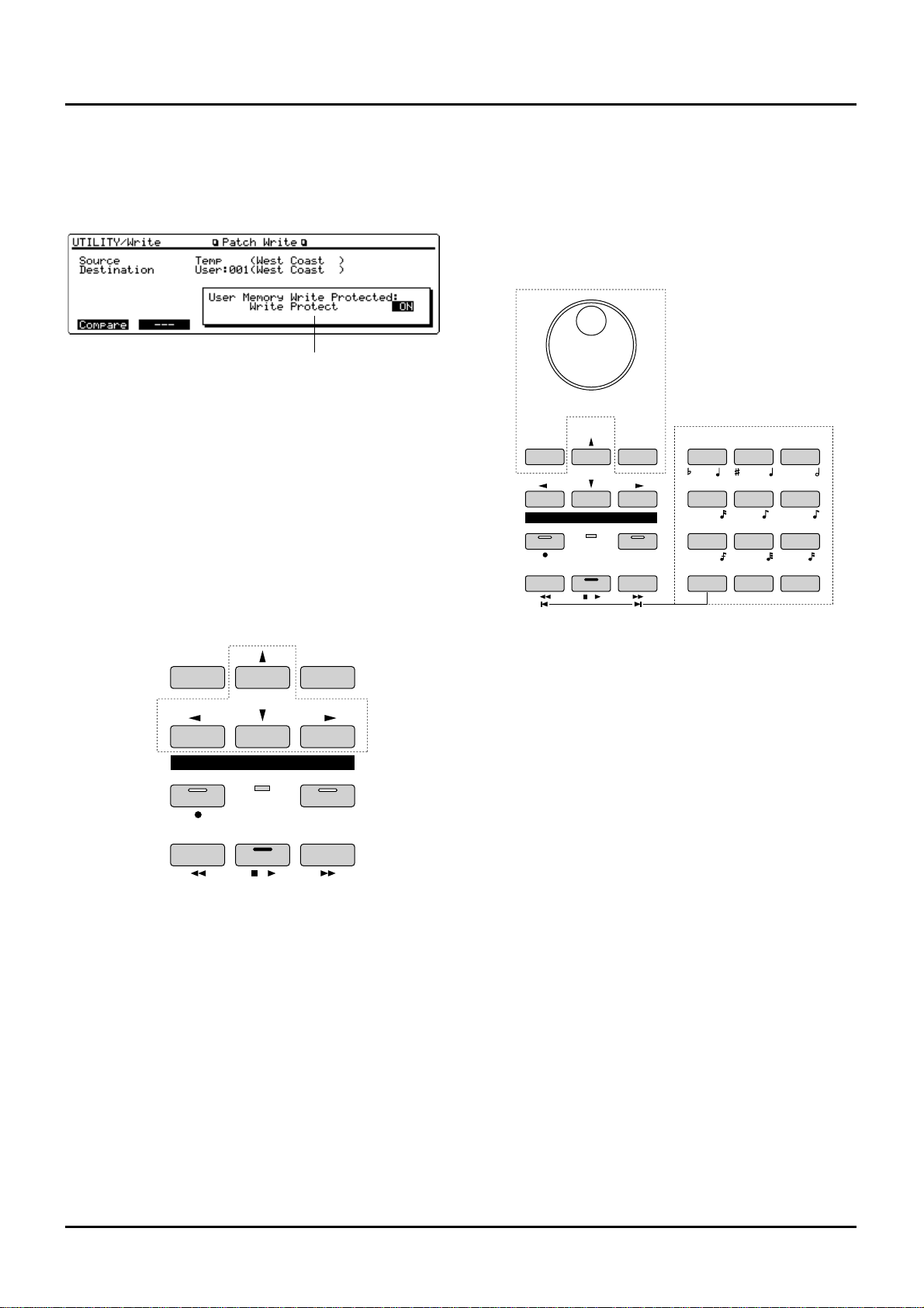
...........................................................................................................
<Windows>
To assist you, a small window box may appear. It can indi-
cate a list, confirm operation, or help input procedure
depending on the situation.
Windows can be opened with their respective buttons and
closed by pressing [EXIT] or the button you used to open it.
Some windows will close automatically after a pertinent
operation is executed.
...........................................................................................................
Moving the cursor
Generally a single display page indicates two or more items
(parameters). Move the cursor (black box with value highlighted) to the parameter whose value you want to set or
modify. Move the cursor with the [u], [d], [l] and [r] (cursor buttons).
[u]: moves the cursor up.
Pressing this button when the cursor is at the upper left
parameter (home position) shifts it to the lower right parameter.
[d]: moves the cursor down.
Pressing this button when the cursor is at the lower right
parameter shifts it to the upper left parameter (home position).
[l]: moves the cursor to the left.
Holding down [SHIFT] while you press this button shifts the
cursor back to home.
[r]: moves the cursor to the right.
✳ If the value of the parameter has not been finalized, the
value on which cursor is positioned is only boxed
without highlighting. Press [ENTER] to finalize the
value and return to the normal display.
Modifying a value
To modify a value, use the VALUE dial, [INC]/[DEC] or
[0]–[9] (numeric keys).
✳ Each parameter has a specific range, so you cannot set
any value smaller than the minimum value or greater
than the maximum value.
VALUE dial
Turning the VALUE dial clockwise increases the value,
counterclockwise decreases the value. Holding down
[SHIFT] as you move the VALUE dial increases value increments so you can make large value changes faster.
[INC] and [DEC]
Pressing [INC] increases the value, and [DEC] decreases it.
Keep [INC] or [DEC] pressed for continuous adjustment. For
faster value increases, keep [INC] pressed down and press
[DEC]. For decreasing value faster, keep [DEC] pressed
down and press [INC].
If you press [INC] or [DEC] while holding down [SHIFT],
the value increments will get bigger.
[0]–[9] (Numeric Keys)
[0]–[9] are called ‘numeric keys’ and are for directly specifying numerical values. When you enter a number using the
numeric keys, the cursor will change from a black box to a
white box, and the highlight of the value will be removed.
Now finalize the value by pressing [ENTER].
To go from a positive to negative value (+/-), or vice versa,
hold down [SHIFT] and press [0].
✳ Some parameters do not require you to [ENTER] them.
Window
SEQUENCER
REC BEAT
BWD FWDSTOP/ PLAY
l
I
LOOP
DEC INC
EF
G
B
C
A DIGIT HOLD
l
D
3
3
3
+ -
SEQUENCER
YZ!VWXSTU
PQRMNOJKL
GHIDEFABC
ENTERSHIFT SPACE
REC BEAT
BWD FWDSTOP/ PLAY
l
I
LOOP
DEC INC
0
123
456
789
Numeric Key
23
Chapter 1. An overview of the XP-80
Page 22
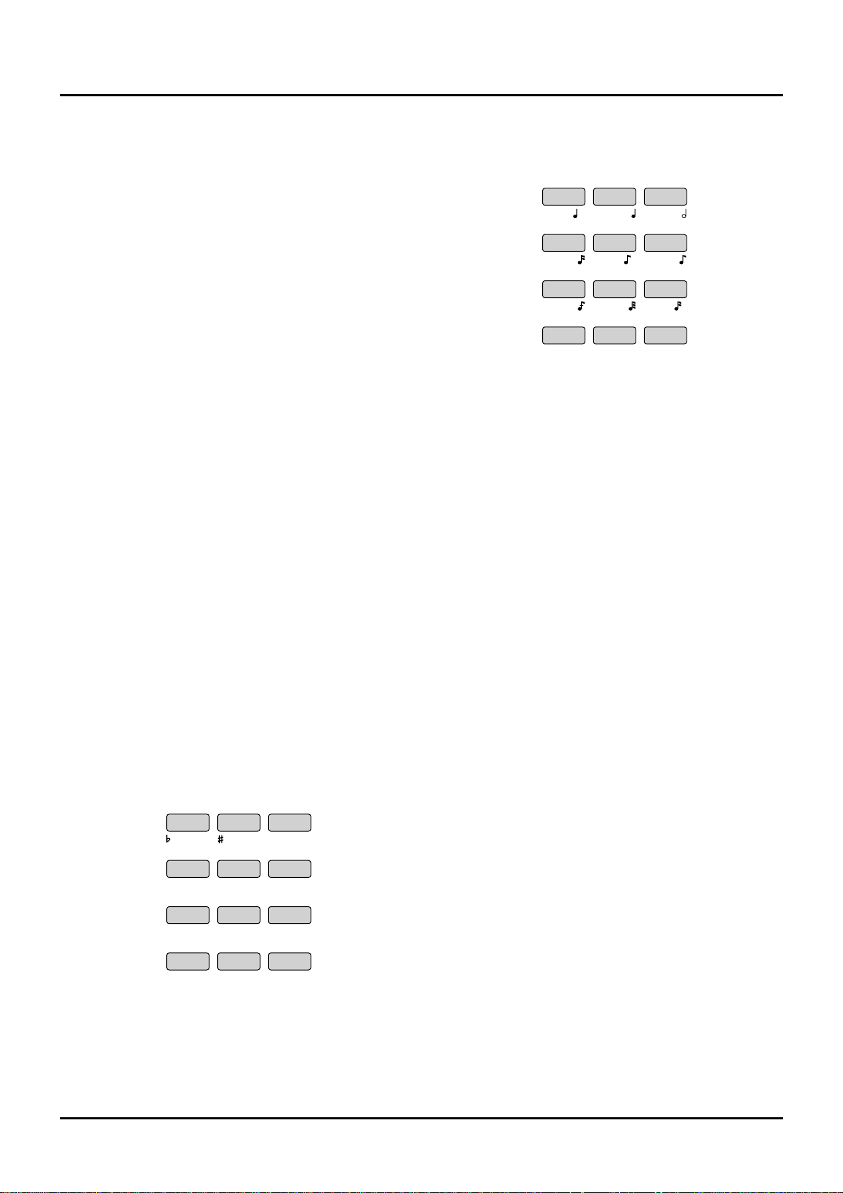
24
(Example)
<To enter a value of 38>
Press [3] → press [8] → press [ENTER].
<To enter a value of -60>
While holding down [SHIFT] press [0] → press [6] → press
[ENTER].
✳ You can switch from a positive to negative numerical
value anytime before you press [ENTER].
Special functions of the numeric keys
You can use the numeric keys to specify non-numerical settings for some parameters.
Performance/Patch/Rhythm Set group
On the Play displays for Performance, Patch or Rhythm Set
mode, you can hold down [SHIFT] and press numeric keys
to specify groups.
Buttons Group
SHIFT+0 USER
SHIFT+1 PR-A (Preset A)
SHIFT+2 PR-B (Preset B)
SHIFT+3 PR-C (Preset C)
SHIFT+4 GM (General MIDI)
SHIFT+5
XP-A (Wave Expansion Board installed in EXP-A Slot)
SHIFT+6
XP-B (Wave Expansion Board installed in EXP-B Slot)
SHIFT+7
XP-C (Wave Expansion Board installed in EXP-C Slot)
SHIFT+8
XP-D (Wave Expansion Board installed in EXP-D Slot)
✳ This procedure also applies when editing
Performances, Patches or Rhythm Sets, and for Utility
mode.
Note name
To enter a note name in Track editing mode or Microscope
editing mode, hold down [SHIFT] and press the appropriate
numeric key. The corresponding note name is at the lower
left of each numeric key.
Note value
Use numeric keys to specify a note value in step recording,
etc. The corresponding note value is at the lower right of
each numeric key.
Characters
When assigning a name for Patches, Performances, files and
songs, you can use the numeric keys to specify alphabetic
characters.
✳ For details, refer to “Assigning a name” below.
Restoring a previous value (Undo)
If you wish to restore a value to its immediate previous
value, press [UNDO/REDO] to return the value to its premodified state.
The Undo function can be used when modifying sound
source settings, recording a song, editing a song, etc.
✳ If you are in the middle of an operation that requires
rewriting large amounts of data (such as song editing),
a message window will show “Memory is low!! So you
cannot undo. Execute anyway?” If you are sure you
won’t have to undo the current operation, press [F5]
(OK). Pressing [F6] (Cancel) cancels the operation.
Assigning a name
The XP-80 allows you to assign a name to data types such as:
Patch, Performance, Rhythm Set, Song, Pattern, Song File,
Chain File, Data File, User Groove Template File, Standard
MIDI File, Volume Label
The procedure is the same for each data type.
<Procedure>
❶ Move the cursor to where you want to input a charac-
ter.
❷ Turn the VALUE dial, or press [INC]/[DEC] to specify
the character.
Available characters/symbols are:
space, A–Z, a–z, 0–9, +-*/|=!?<>()[]{}:;.,"'`#%&$\@^_
Lowercase characters and some symbols (+*/|=?<>[]:;.,"\)
cannot be used for filenames and volume labels.
✳ You can also use numeric keys to select alphabet or
numeric characters.
EF
G
B
C
A
D
3
3
3
Chapter 1. An overview of the XP-80
Page 23
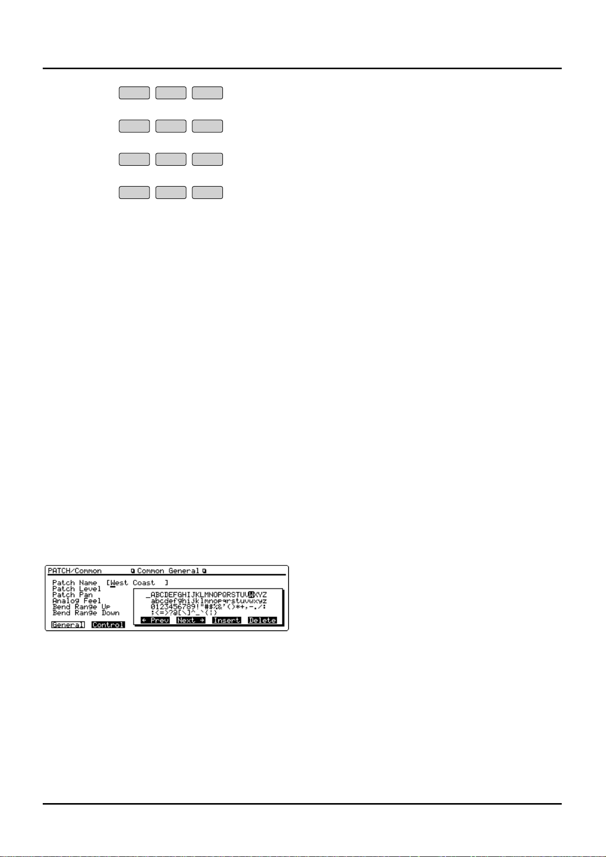
Each time you press a numeric key, the display will cycle
through the characters and numerals printed above each
key. For instance, pressing [1] will make the display change
1→A→B→C→1→A... To specify lowercase characters, hold
down [SHIFT] and press the numeric key.
❸ Repeat steps 1 and 2 as necessary.
✳ If you enter a space in filenames or volume labels, it
will be replaced with an underline “__” after the operation is executed. However, a blank entered at the end
of a name will be left as a blank.
Assigning a name using a Name window
You can use a Name window to assign a name. As the Name
window displays a list of characters that can be entered, you
can quickly select a desired character.
<Procedure>
❶ From any display in which you can assign a name,
press the following buttons to open a Name window.
Name Button
Patch [F1] (General)
Performance [F1] (Common)
Rhythm Set [F1] (Common)
Song [F1] (SngName)
Pattern [F2] (PtnName)
Filenames and volume labels [F1] (Name)
❷ Press [F3] (←Prev) or [F4] (Next→) to move the cursor
to the location where you wish to input a character.
❸ Press cursor buttons or [INC]/[DEC], or turn the
VALUE dial to specify the character.
To enter a space at the cursor position, press [F5] (Insert).
To delete the character at the cursor position, press [F6]
(Delete).
❹ Repeat steps 2 and 3 as necessary.
❺ After assigning a name, press [EXIT] or the button you
used to open the Name window to close it.
YZ!VWXSTU
PQRMNOJKL
GHIDEFABC
SPACE0
123
456
789
25
Chapter 1. An overview of the XP-80
Page 24
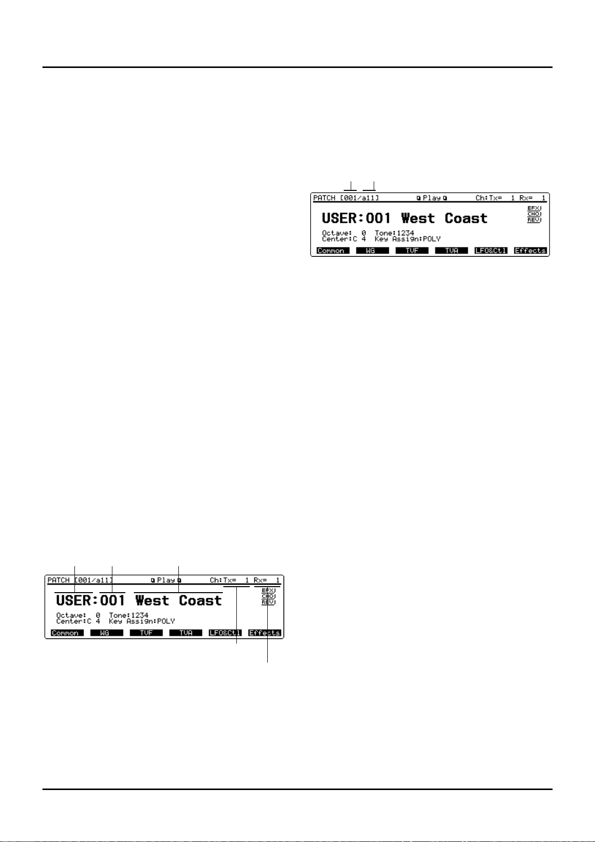
26
❚
Playing in Patch mode
Patches are what you normally play during a performance.
Select a Patch before playing.
Selecting a Patch
The XP-80 offers five groups of Patches (User, Presets A–C
and GM) with each group having 128 Patches for a total of
640 Patches.
Up to four optional Wave Expansion Boards can be installed
to provide a whopping 1,660 Patches.
USER
The XP-80’s user memory contains 128 Patches that can be
rewritten to create your own Patches.
PR-A–C (Presets A–C)
The XP-80 includes 384 preset Patches that are not userrewritable. But you can call up preset Patch settings into the
temporary area, modify them, and then store them in User
memory.
GM (General MIDI)
GM Patches are for instruments compatible with the GM
System. The aim of this system is to standardize MIDI specifications among different equipment makers or models. The
XP-80 contains 128 GM Patches that are not user-rewritable.
But you can call up GM Patch settings into the temporary
area, modify them, and then store them in User memory.
XP-A–D (Wave Expansion Boards installed in EXP-A–D Slots)
The Patches included in optional Wave Expansion Boards
are not user-rewritable. But you can call up those Patch settings into the temporary area, modify them, and then store
them in User memory.
✳ A Patch XP-A–D cannot be accessed if the Wave
Expansion Board it belongs to has not been installed.
<Procedure>
❶ Press [PATCH] to call up the Play display (PATCH).
❷ Turn the VALUE dial or press [INC]/[DEC] to select a
Patch.
Selecting a Patch with Bank/Number method
You can select a Patch by combining BANK [1]–[8] and
NUMBER [1]–[8] buttons in the center of the front panel.
This selection style is called the ‘Bank/Number method.’
When selecting a Patch on the XP-80 using the
Bank/Number method, the bank/number corresponding to
each Patch number is shown at the upper left of the display.
Patch number: 001 002 003 ... 064 065 066 067
Bank/number: a11 a12 a13 ... a88 b11 b12 b13 ... b88
With the Bank/Number method, 64 Patches in bank 1/num-
ber 1 through bank 8/number 8 make up a single subgroup.
Subgroups (a/b/c/d) can be changed in units of 64 Patches.
✳ Subgroup c or d can be chosen only when selecting a
Patch from a Wave Expansion Board.
<Procedure>
❶ Press [PATCH] to call up the Play display (PATCH).
❷ Turn the VALUE dial, or press [INC]/[DEC] or numer-
ic keys to select a Patch group.
❸ Press [a/b/c/d] to select a subgroup. Subgroups a and
b will be toggled each time the button is pressed.
✳ When selecting a Patch from a Wave Expansion Board,
pressing this button will cycle through subgroups a, b,
c, and d.
❹ Press BANK [1]–[8] to select a bank.
❺ Press NUMBER [1]–[8] to select a number.
Selecting a Patch using numeric keys
You can use numeric keys to directly select a desired Patch.
<Procedure>
❶ Press [PATCH] to call up the Play display (PATCH).
❷ Hold down [SHIFT] and press numeric keys [0]–[8] to
select a Patch group.
Patch group Numeric key
USER [SHIFT] + [0]
PR-A [SHIFT] + [1]
PR-B [SHIFT] + [2]
PR-C [SHIFT] + [3]
GM [SHIFT] + [4]
XP-A [SHIFT] + [5]
XP-B [SHIFT] + [6]
XP-C [SHIFT] + [7]
XP-D [SHIFT] + [8]
Patch group Patch number Patch name
Patch transmit
channel
Patch receive
channel
Patch number Bank/Number
Chapter 2. Playing
Chapter 2. Playing
Page 25
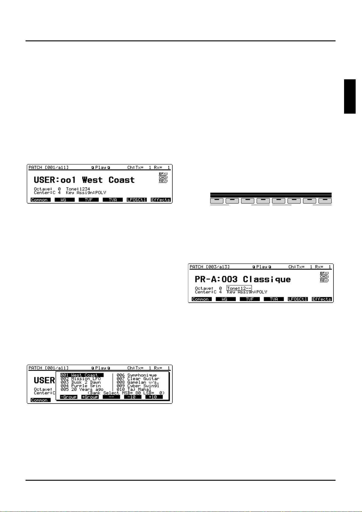
❸ Use numeric keys to input a Patch number (001–128).
The Patch number and Patch name are boxed, meaning the
entry has not yet been finalized.
❹ Press [ENTER] to finalize the entry.
...........................................................................................................
<Express Patch select (Digit Hold)>
With the Digit Hold function turned on, the 100’s position
and 10’s position will be fixed when the numeric keys are
used to select a Patch. This means that the numeric keys will
only change the 1’s position, and you won’t have to press
[ENTER] for each selection. The same applies to selecting
Performances and Rhythm Sets.
<Procedure>
❶ Hold down [SHIFT] and press [ENTER] to turn on
Digit Hold.
The numbers in the 100’s position and 10’s position will be
displayed in a smaller size to indicate Digit Hold is on.
❷ When you enter a numeric key number, the 1’s posi-
tion will change immediately without having to press
[ENTER].
❸ To turn off Digit Hold, hold down [SHIFT] and press
[ENTER] once again.
...........................................................................................................
Displaying a Patch list
You can view a Patch list when selecting a Patch. Ten
Patches are displayed at once for each Patch group, allowing
your desired Patch to be quickly accessed. This Patch list is
called the ‘Sound List window.’
<Procedure>
❶ Make sure that the Play display (PATCH) is showing.
❷ Press [SOUND LIST] to display the Sound List win-
dow. The cursor is on the currently selected Patch.
(Bank Select MSB=, LSB=) at the bottom line indicates
the Bank Select (MSB and LSB) of the current Patch.
❸ When changing Patches in units of 10, press either [F5]
(-10) or [F6] (+10). Holding down either button will
change Patch groups as well. Patch groups can also be
changed by pressing [F2] (-Group) or [F3] (+Group).
❹ When selecting a Patch, turn the VALUE dial, or press
[INC]/[DEC] or cursor buttons to move the cursor to
the desired Patch.
❺ Press [EXIT] to close the Sound List window.
Making a Patch sound thick or thin
(turning a Tone on/off)
Since a Patch is a combination of up to four Tones, you can
switch unwanted (Tones out of the four) off and get just the
sound of a specific Tone.
✳ Use the Tone Switch parameter (PATCH/WG/Wave
Param) to set each Tone on/off. This setting can be
stored as a part of Patch data. So if you want just one
or two Tones to sound in a Patch, turn the others off
and store that setting on a Patch. This cuts nonessential
use of the XP-80’s simultaneous voices.
<Procedure>
❶ Make sure that the Play display (PATCH) is showing.
❷ Press any button from [F1] (Common)–[F6] (Effect).
❸ Use TONE SWITCH [1]–[4] (BANK [1]–[4] ) to turn
Tones on (indicator lights) or off (indicator off).
TONE SWITCH buttons switch Tones 1, 2, 3, and 4 on/off in
sequence going from left to right.
❹ Press [EXIT] to return to the Play display (PATCH)
and start playing the Patch.
“Tone:” at the display bottom center shows the numbers of
Tones which are turned on. The Tones turned off are indicated with “-.”
1 2 3 4 5 6 7 8
1 2 3 4
TONE 1 TONE 2 TONE 3 TONE 4
5 6 7 8
TRACK/ PART
BANK
TONE SWITCH
TONE SELECT
27
Chapter 2. Playing
1
2
3
4
5
6
7
8
9
10
11
12
Page 26
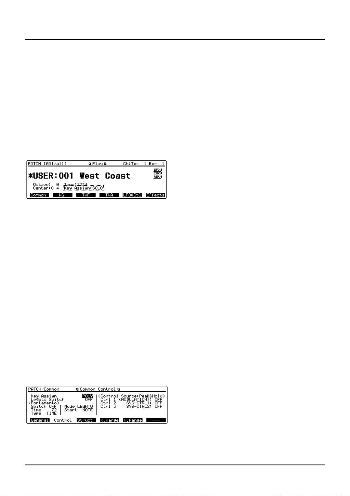
28
Playing single notes (Solo)
Normally, the XP-80 allows you to play chords. Pressing
[SOLO] allows performance using single notes. This function
is effective when performing a solo using single-note
Patches like sax and flute.
✳ The Solo function on/off setting can be stored as a part
of each Patch setting using the Key Assign parameter
(PATCH/Common/Common Control).
<Procedure>
❶ Make sure that the Play display (PATCH) is showing.
❷ Press [SOLO] so its indicator lights.
Now you can play a solo.
✳ This setting is also shown for “Key Assign” at the bot-
tom center of the display.
❸ Play the XP-80 keyboard.
✳ If you press [SOLO] when Single Performance is select-
ed, the Solo function can be switched on or off for the
current Part. When Layer Performance is selected, the
Solo function can be switched on or off for the Parts
with the Local Switch parameter (PERFORM/MIDI/
Part MIDI) set ON. If a Rhythm Set is selected, [SOLO]
cannot be turned on.
Creating smooth pitch changes
(Portamento)
Portamento ensures a smooth pitch changeover from one
note to the next note played. When [SOLO] is on (indicator
lights), you can simulate techniques like violin glissandos.
✳ The Portamento function on/off setting can be stored
as a part of each Patch setting using the Switch parameter (PATCH/Common/Common Control).
<Procedure>
❶ Make sure that the Play (PATCH) display is showing.
❷ Press [PORTAMENTO]. Its indicator lights.
You’re ready to play portamento.
❸ To adjust portamento, Press [F1] (Common), then [F2]
(Control) to call up the Common Control display
(PATCH/Common).
❹ Move the cursor over to Time, Type, Mode or Start
parameter.
See p.47 for each parameter’s functions.
❺ Turn the VALUE dial or press [INC]/[DEC] to get the
value you want.
❻ Press [EXIT] to return to the Play display (PATCH)
and play.
✳ If you press [PORTAMENTO] when Single
Performance is selected, the Portamento function can
be switched on or off for the current Part. When Layer
Performance is selected, the Portamento function can
be switched on or off for the Parts with the Local
Switch parameter (PERFORM/MIDI/Part MIDI) set
ON. If a Rhythm Set is selected, [PORTAMENTO] cannot be turned on.
Quick sound character changes
(Sound Palette)
With the four sliders in the Sound Palette section, you can
create sound variations or volume changes in real time.
✳ Sound variations or volume changes made with the
Sound Palette affect only the performance. They have
no effect on current Patch settings. Change the Patch
and these Sound Palette settings will be lost.
✳ The sound character and volume changes created
using the Sound Palette will also be transmitted to the
XP-80’s sequencer and external MIDI devices.
Changing sound characters
<Procedure>
❶ Make sure that the Play display (PATCH) is showing.
❷ Press [FILTER/ENV] and its indicator lights.
❸ Move the sliders while you play to vary the sound.
To modify the brightness, move the CUTOFF slider.
To change resonance, move the RESO. slider.
To change attack time, move the ATTACK slider.
To change decay time, move the DECAY slider.
Changing the volume of each Tone
<Procedure>
❶ Make sure that the Play display (PATCH) is showing.
❷ Press [LEVEL] and its indicator lights.
❸ Move the LEVEL slider as you play the keyboard to
adjust volume as desired.
Sliders 1, 2, 3, and 4 are used to change the volume of Tones
1, 2, 3, and 4, respectively.
Chapter 2. Playing
Page 27
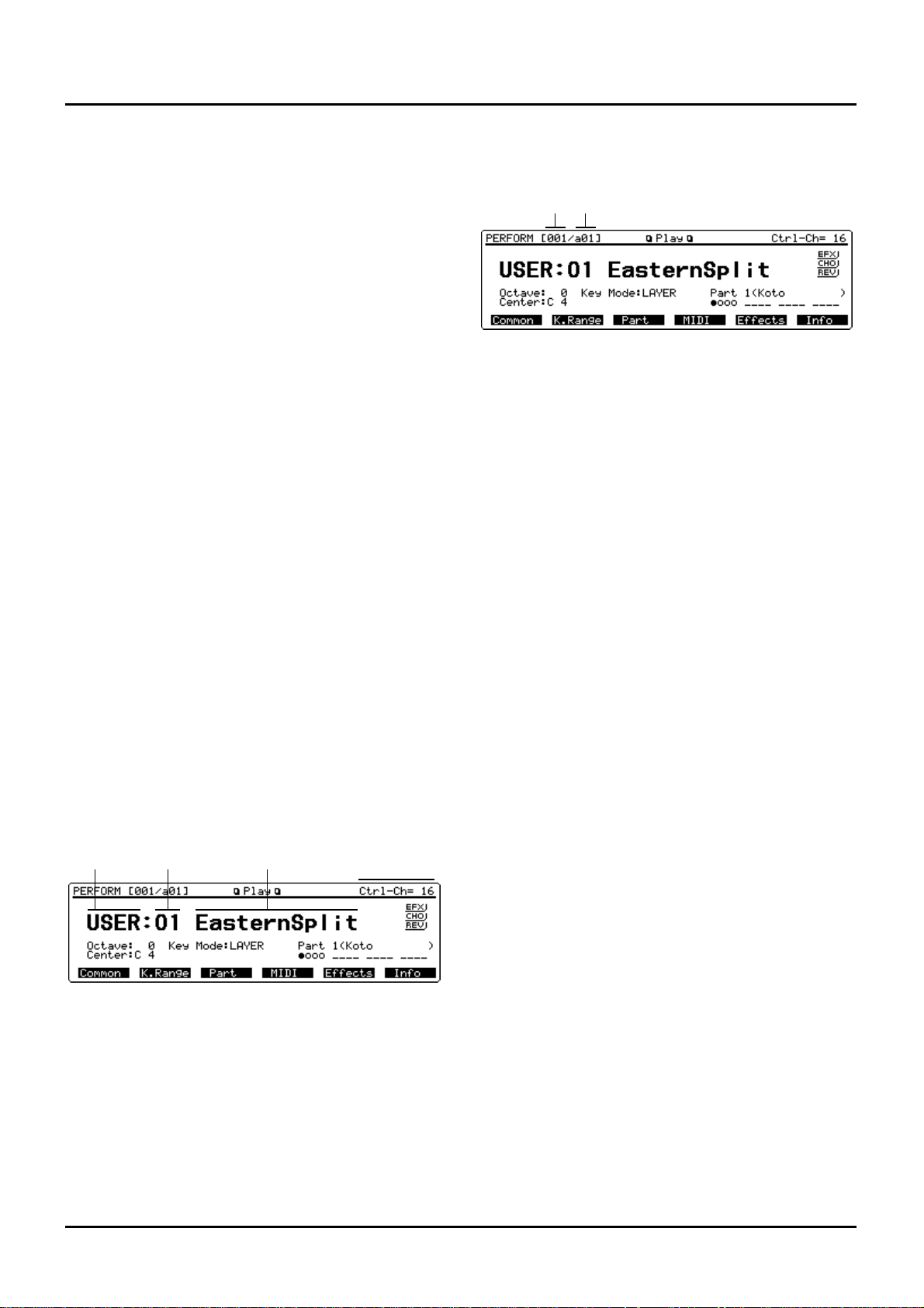
❚
Playing in Performance mode
There are Single and Layer Performances. The “Key
Mode:LAYER” indication under the Performance name represents Layer Performance, while the “Key Mode:SINGLE”
indication represents Single Performance.
Layer Performance allows playing two or more Parts simultaneously on the keyboard. Select Layer Performance if you
want fat, rich sounds of two or more Patches, or play different Patches in a split keyboard’s different sections.
Single Performance plays only the Part shown in the display
(current Part). Select Single Performance for playing a song
using two or more instruments.
✳ Make your Performance type selection with the Key
Mode parameter (PERFORM/Common/Common) .
The Key Mode parameter determines how the XP-80
keyboard will play the internal sound source. It has no
effect on how the XP-80 sound source is played from
the built-in sequencer or an external MIDI device.
Selecting a Performance
The XP-80 offers three groups of Performances (User, Presets
A and B) with each group having 32 Performances. A total of
96 Performances is available.
USER
The XP-80 user memory includes 32 Performances that can
be rewritten to produce your own Performances.
PR-A–B (Preset A–B)
The XP-80 contains 64 preset Performances that cannot be
rewritten. But you can call up preset Performance settings
into the temporary area, modify them, and then store them
in user memory.
<Procedure>
❶ Press [PERFORM] to call up the Play display (PER-
FORM).
❷ Turn the VALUE dial or press [INC]/[DEC] to select a
Performance.
Selecting a Performance with Subgroup/Number
method
You can select a Performance using TRACK/PART [1]–[16]
at front panel center. Each Performance group contains 32
Performances, so you can choose a Performance using 16
buttons in subgroups a and b.
If you use this method to select a Performance, you’ll see the
subgroup and number corresponding to each Performance
number at the upper left of the display.
Performance number:01 02 03 ... 16 17 18 19 ... 32
Subgroup/number: a01 a02 a03 ... a16 b01 b02 b03 ... b16
<Procedure>
❶ Press [PERFORM] to call up the Play display (PER-
FORM).
❷ Turn the VALUE dial, or press [INC]/[DEC] or numer-
ic keys to select a Performance group.
❸ Press [a/b/c/d] to select a subgroup. Subgroups a and
b will toggle with each button press.
❹ Press a button from TRACK/PART [1]–[16] to select a
number.
Selecting a Performance using numeric keys
You can choose a Performance with direct numeric key
input.
<Procedure>
❶ Press [PERFORM] to call up the Play display (PER-
FORM).
❷ Hold down [SHIFT] and press numeric keys [0]–[2]
corresponding to your desired Performance group.
Performance group Numeric key
USER [SHIFT] + [0]
PR-A [SHIFT] + [1]
PR-B [SHIFT] + [2]
❸ Use numeric keys to input the Performance number
(001–032).
The Performance number and Performance name are boxed,
indicating that the Performance has not yet been finalized.
❹ Press [ENTER] to finalize the entry.
✳ Using Digit Hold, a Performance can be selected sim-
ply by specifying the 1’s place number (p.27).
Displaying a Performance’s Sound List
window
A Performance Sound List window can be viewed. Ten
Performances are displayed in sequential order at one time
for each Performance group so you can quickly select the
desired Performance.
<Procedure>
❶ Make sure that the Play display (PERFORM) is show-
ing.
❷ Press [SOUND LIST] to display the Sound List win-
dow.
Performance
group
Performance
number
Performance
name
Control
channel
Performance
number
Subgroup/Number
29
Chapter 2. Playing
Page 28
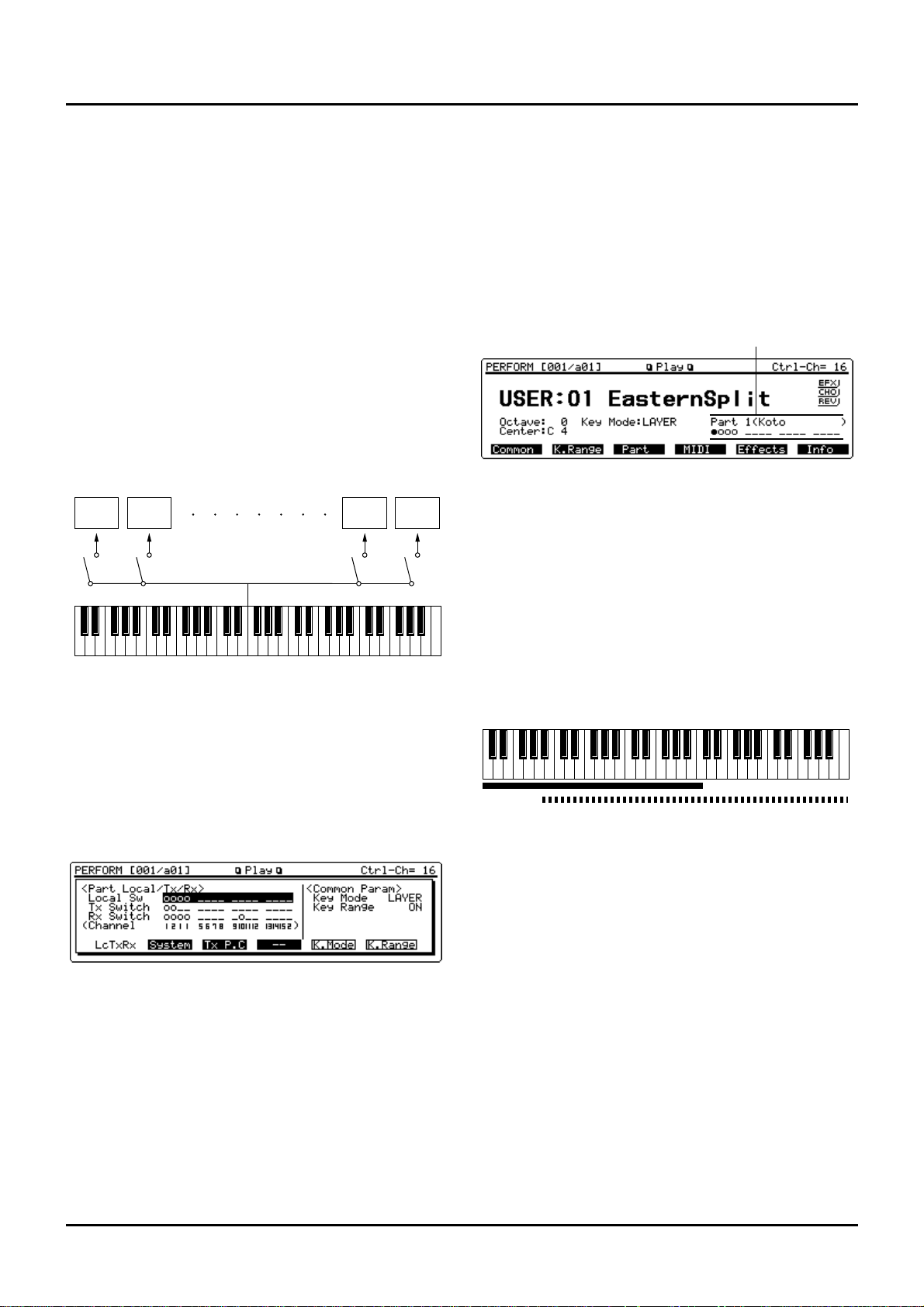
30
The cursor is at the current Performance. (Bank Select MSB=,
LSB=) at the bottom line indicates the Bank Select (MSB and
LSB) of the current Patch.
❸ When changing Performances in units of 10, press
either [F5] (-10) or [F6] (+10).
Holding down either button will change Performance
groups as well. Performance groups can also be changed by
pressing [F2] (-Group) or [F3] (+Group).
❹ When selecting a Performance, turn the VALUE dial,
or press [INC]/[DEC] or cursor buttons to move the
cursor to the desired Performance.
❺ Press [EXIT] to close the Sound List window.
Playing fatter and richer sounds by combining Patches (Layer)
If a Layer Performance is selected, you can play all Parts
with the Local Sw parameter (PERFORM/MIDI/Part MIDI)
ON. Combining the Parts will produce, thicker, fatter
sounds.
<Procedure>
❶ Make sure that Play display (PERFORM) is showing.
❷ Note “Key Mode:LAYER” is below the Performance
name.
If “Key Mode:SINGLE” is displayed, it means that a Single
Performance is selected. Change it to Layer Performance.
❸ Press [LOCAL/TX/RX] to open the LOCAL/TX/RX
window.
❹ Press [F5] (K.Mode) to select LAYER.
Pressing this button again re-selects SINGLE.
✳ If you set the Key Mode parameter in the LOCAL/TX/
RX window, the Key Mode parameter (PERFORM/
Common/Common) value will also change.
❺ Making sure that the cursor is positioned at the Local
Sw parameter, press TRACK/PART [1]–[16] to turn on
the Part you want to hear (indicator lit).
The display will indicate “o” for the Parts with Local Sw
parameter ON and “-” for the Parts with Local Sw parameter
OFF.
✳ The setting you make in the LOCAL/TX/RX window
will also affect the Local Sw parameter value (PERFORM/MIDI/Part MIDI).
❻ After you complete your settings, press [LOCAL/TX/
RX] or [EXIT] to close the LOCAL/TX/RX window
and return to the Play display (PERFORM). Now start
playing.
The lower right of the display will indicate “o” for the Parts
with Local Sw parameter ON and “-” for the Parts with
Local Sw parameter OFF. The cursor is located on the current Part selected.
Splitting the keyboard to play separate
Patches in different sections (Split)
If you’ve selected a Layer Performance, you can split the
keyboard to play separate Patches with different sections of
the keyboard. As the note range that plays each Part can be
specified individually, you can split the keyboard into a
maximum of 16 sections.
For instance, you can play strings in the lower note section,
piano in the higher note section and both sounds in the middle note section.
✳ If a K.Range Lower:Upper display(PATCH/Common)
has been set, sounds are produced in the overlapping
sections between the key ranges specified for the Patch
and Performance.
<Procedure>
❶ Make sure that the Play display (PERFORM) is show-
ing.
❷ Press [LOCAL/TX/RX] to open the LOCAL/TX/RX
window.
❸ If you have selected a Single Performance, Press [F5]
(K.Mode) to select LAYER.
Pressing this button again re-selects SINGLE.
✳ If you set the Key Mode parameter in the LOCAL/TX/
RX window, the Key Mode parameter (PERFORM/
Common/Common) value will also change.
❹ Making sure that the cursor is positioned at the Local
Sw parameter and press a button from TRACK/PART
[1]–[16] so the button indicator of the Part you wish to
play lights.
Part 1 Part 2 Part 15 Part 16
Local Sw parameters
Current part (Patch name)
Part 1: Strings
Part 1 + Part 2:
(Strings + Piano)
Part 2: Piano
Chapter 2. Playing
Page 29
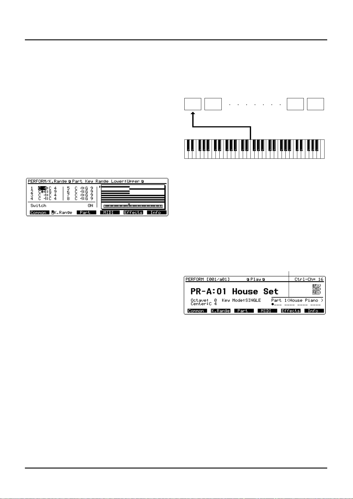
On the display, Parts with Local Sw parameter ON are
shown with “o,” and those with Local Sw parameter OFF
with “-.”
✳ The setting you make in the LOCAL/TX/RX window
will also affect the Local Sw parameter value (PERFORM/MIDI/Part MIDI).
❺ Make sure that the Key Range parameter is set ON. If
OFF, press [F6] (K.Range) to set it ON.
✳ If the Key Range parameter is OFF, the keyboard can-
not be split even when you set the key range.
✳ If you set the Key Range parameter in the LOCAL/
TX/RX window, the switch parameter (PERFORM/
K.Range/Part Key Range Lower:Upper) value will also
change.
❻ After completing your settings, press [LOCAL/TX/
RX] or [EXIT] to close the LOCAL/TX/RX window.
❼ Press [F2] (K.Range) to call up the Part Key Range
Lower:Upper display (PERFORM/Common).
✳ Part Key Range Lower:Upper display (PERFORM/
Common) is available in two pages: one for displaying
Parts 1 through 8 and the other for displaying Parts 9
through 16. To flip between these two pages, press [F2]
(K.Range).
❽ Move the cursor to a Part with Local Sw parameter ON
and specify the note range while confirming this operation on the display.
The value at left of each Part indicates the lowest note
(lower) and the value at right indicates the highest note
(upper).
✳ By specifying sections for different Parts so that they
overlap each other, you can combine two or more
Patches only in a specific section.
❾ After completing your settings, press [EXIT] to return
to the Play display (PERFORM) and start playing.
Playing along with a song playback (XP-80
used as a multitimbral sound source)
When a Single Performance is selected, the XP-80’s keyboard
will play only the Part you selected from the keyboard, convenient when you play the keyboard along with a song playback.
Selecting a Part you want to play on the keyboard
If a Single Performance is selected, press [l] or [r] to select
the Part you want to play. The selected Part is called the
‘current Part.’
<Procedure>
❶ Make sure that the Play display (PERFORM) is show-
ing.
❷ Press [l] or [r] to choose the Part to be played.
The current Part number will be seen at the lower right of
the display with the Patch name indicated within parentheses ( ). The cursor($) also moves to the current Part.
Muting a specific Part (turning Receive channel
on/off)
While you play along with the playback of a song, you can
turn on/off any specific Part. This allows you to turn off the
melody Part for karaoke applications or for practicing the
muted Part.
<Procedure>
❶ Press [LOCAL/TX/RX] to open the LOCAL/TX/RX
window.
❷ Move the cursor to the Rx Switch parameter and press
a button from TRACK/PART [1]–[16] to mute the Part.
The button indicator of the muted Part will go off.
On the display, Parts which are on are shown with “o,” and
those off are shown with “-.”
✳ The setting you make in the LOCAL/TX/RX window
will also affect the Rx Switch parameter value (PERFORM/MIDI/Part MIDI).
Part 1 Part 2 Part 15 Part 16
Current part (Patch name)
31
Chapter 2. Playing
Page 30
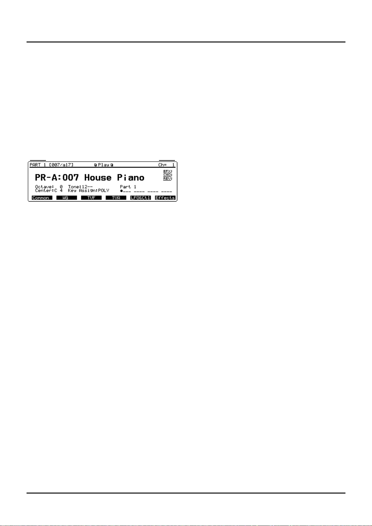
32
Assigning a different Patch to a Part
✳ The Patch assigned to each Part can be stored as a part
of a Performance using Patch Group parameter and
Patch Number parameter (PERFORM/Part/Part
Param).
<Procedure>
❶ Make sure that the Play display (PERFORM) is show-
ing.
❷ Press [l] or [r] to choose the Part to which you want
to assign a different Patch.
❸ While holding down [PERFORM], press [PATCH] or
[d] to call up the Play display of the Patch assigned to
a specific Part.
The current Part number is shown at the lower right of the
display and the cursor moves to the Part.
❹ Use the same procedure as in Patch mode to select a
Patch.
❺ Press [PERFORM] or [EXIT] or [u ] to return to the
Play display (PERFORM).
Quick sound character changes
(Sound Palette)
Using the Sound Palette function, you can modify sound
characters of the Patch assigned to a Part or adjust the volume level of each Part.
✳ Sound variations or volume changes made with the
Sound Palette function affect only the performance.
They have no effect on the currently selected
Performance, so the Sound Palette settings cannot be
saved. If you change the Performance, these settings
will be lost.
✳ The sound character and volume changes created
using the Sound Palette will also be transmitted to the
XP-80’s sequencer and external MIDI devices.
Changing sound characters
✳ If Single Performance is selected, the effect applies
only to the current Part. With Layer Performance
selected, this affects only the Parts with Local Switch
parameter (PERFORM/MIDI/Part MIDI) set ON.
<Procedure>
❶ Make sure that the Play display (PERFORM) is show-
ing.
❷ Press [FILTER/ENV] to light its indicator.
❸ Move the sliders while you play the XP-80’s keyboard
to vary the sound.
To change brightness, move the CUTOFF slider.
To change resonance, move the RESO slider.
To change attack time, move the ATTACK slider.
To change decay time, move the DECAY slider.
Changing the level (volume) of each Part
<Procedure>
❶ Make sure that the Play display (PERFORM) is show-
ing.
❷ Press [LEVEL] to light its indicator.
❸ Press [l] or [r] to select the Part whose level (volume)
you want to change.
If you’ve selected any of Parts 1–4, sliders 1, 2, 3, and 4
adjust Parts 1, 2, 3, and 4, respectively.
If you’ve selected any of Parts 5–8, sliders 1, 2, 3, and 4
adjust Parts 5, 6, 7, and 8, respectively.
If you’ve selected any of Parts 9–12, sliders 1, 2, 3, and 4
adjust Parts 9, 10, 11, and 12, respectively.
If you’ve selected any of Parts 13–16, sliders 1, 2, 3, and 4
adjust Parts 13, 14, 15, and 16, respectively.
❹ Move the slider as you play to adjust the level (vol-
ume) of each Part as desired.
Current part
MIDI channel
Chapter 2. Playing
Page 31

❚
Playing in Rhythm Set mode
In Rhythm Set mode, you can play Rhythm Tones on the
keyboard. As the percussion instrument assigned to each
key varies by the Rhythm Set selected, you can play a wide
range of percussion instruments.
Selecting a Rhythm Set
The XP-80 offers five groups of Rhythm Sets (User, Presets
A–C and GM) with each group having two Rhythm Sets – a
total of 10 Rhythm Sets. In addition, up to four optional
Wave Expansion Boards can be installed for accessing even
more percussion instruments.
USER
The XP-80’s user memory contains two Rhythm Sets that can
be rewritten to make up your own Rhythm Sets.
PR-A–C (Presets A–C)
The XP-80 includes six preset Rhythm Sets that are not userrewritable. But you can call up preset Rhythm Set settings
into the temporary area, modify them, and then store them
in user memory.
GM (General MIDI)
GM Rhythm Sets are for instruments compatible with the
General MIDI System intended to standardize MIDI specifications among different equipment makers or models. The
XP-80 offers two GM Rhythm Sets that are not userrewritable. But you can call up GM Rhythm Set settings into
the temporary area, modify them, and then store them in
user memory.
XP-A–D (Wave Expansion Boards installed in EXP-A–D Slots)
These Rhythm Sets are included in optional Wave Expansion
Boards and are not user-rewritable. But you can call up
Rhythm Set settings into the temporary area, modify them,
and then store them in user memory.
✳ A Patch XP-A–D cannot be accessed if the Wave
Expansion Board it belongs to has not been installed.
<Procedure>
❶ Press [RHYTHM] to call up the Play display
(RHYTHM).
❷ Turn the VALUE dial or press [INC]/[DEC] to select a
Rhythm Set.
Selecting a Rhythm Set with Bank/Number method
You can select a Rhythm Set by combining BANK [1]–[8]
and NUMBER [1]–[8] located at front panel center. This is
called ‘Bank/Number method.’ However, when you select a
Rhythm Set stored in the XP-80, Bank is fixed at 1. So specify
the number by pressing NUMBER [1] or [2] only.
The bank/number corresponding to each Rhythm Set number is shown at the upper left of the display for your reference when selecting a Rhythm Set using the Bank/Number
method.
Rhythm Set number: 001 002 .... 008
Bank/number: a11 a12 ... a18
<Procedure>
❶ Press [RHYTHM] to call up the Play display
(RHYTHM).
❷ Turn the VALUE dial, or press [INC]/[DEC] or numer-
ic keys to select a Rhythm Set group.
❸ Press NUMBER [1]–[8] to select a number.
✳ When selecting a Rhythm Set from a Wave Expansion
Board, a bank and subgroup may have to be specified.
For details, refer to the Owner’s Manual for optional
Wave Expansion Boards.
Rhythm set
group
Rhythm set
number
Rhythm set
name
MIDI channel
Rhythm set
number
Bank/Number
33
Chapter 2. Playing
Page 32

34
Selecting a Rhythm Set using numeric keys
Using numeric keys, you can direct input a desired Rhythm
Set.
<Procedure>
❶ Press [RHYTHM] to call up the Play display
(RHYTHM).
❷ Hold down [SHIFT] and press numeric keys [0]–[8] to
select a Rhythm Set group.
Rhythm Set group Numeric key
USER [SHIFT] + [0]
PR-A [SHIFT] + [1]
PR-B [SHIFT] + [2]
PR-C [SHIFT] + [3]
GM [SHIFT] + [4]
XP-A [SHIFT] + [5]
XP-B [SHIFT] + [6]
XP-C [SHIFT] + [7]
XP-D [SHIFT] + [8]
❸ Use numeric keys to input a Rhythm Set number
(001–002).
The Rhythm Set number and name are boxed, meaning the
entry has not yet been finalized.
❹ Press [ENTER] to finalize the entry.
✳ Using Digit Hold, a Rhythm Set can be selected simply
by specifying the 1’s place number (p.27).
Displaying Sound List window of a
Rhythm Set
The Sound List window for each Rhythm Set group is displayed so you can quickly choose a Rhythm Set.
<Procedure>
❶ Make sure that the Play display (RHYTHM) is show-
ing.
❷ Press [SOUND LIST] to display the Sound List win-
dow.
The cursor is on the currently selected Rhythm Set. (Bank
Select MSB=, LSB=) at the bottom line indicates the Bank
Select (MSB and LSB) of the current Patch.
❸ To call up another Rhythm Set group, press [F2] (-
Group) or [F3] (+Group).
✳ You can also change Rhythm Set groups by continu-
ously pressing [F5] (-10) or [F6] (+10).
❹ When selecting a Rhythm Set, turn the VALUE dial, or
press [INC]/[DEC] or cursor buttons to move the cursor to the desired Rhythm Set.
❺ Press [EXIT] to close the Sound List window.
Playing percussion instruments
<Procedure>
❶ Press [RHYTHM] to call up the Play display
(RHYTHM).
❷ Select a desired Rhythm Set.
❸ Press a key on the keyboard to play a Rhythm Tone.
The key (Note name) you press and its Rhythm Tone name
(the same as the Wave it uses) will be displayed below the
Rhythm Set name.
Note name
Percussion instrument name
Chapter 2. Playing
Page 33

❚
Playing an arpeggio
The XP-80’s Arpeggiator lets you produce an arpeggio (broken chord) simply by playing a chord. In addition to normal
arpeggios, you can also accurately simulate guitar cutting or
strumming techniques depending on the Arpeggiator settings. The Arpeggiator can in fact be used as a handy automatic arranger.
By pressing [ARPEGGIO], the indicator lights and allows
playing arpeggios from the XP-80 keyboard.
✳ If you press [ARPEGGIO] to turn this function on
when Single Performance is selected, the current Part
will play arpeggios. When a Layer Performance is
selected, an arpeggio will sound for the Part specified
by the Part parameter (SYSTEM/Arpeg/Arpeggo).
✳ The arpeggios played by the arpeggiator are also trans-
mitted from the MIDI OUT connector to external MIDI
devices.
(Basic Procedure)
❶ Make sure that the Play display of a sound source
mode (PERFORM, PATCH, RHYTHM or GM) is up.
❷ Press [ARPEGGIO] to turn the Arpeggiator on.
The Arpeggio window for setting Arpeggiator parameters
opens.
✳ If the Play display of a sequencer mode (SEQ or
CHAIN) is up, it is possible to turn the Arpeggiator on
(the button indicator is lit) but the Arpeggio window
will not open.
✳ To change the sound while the Arpeggio window is
open, use BANK [1]–[8], NUMBER [1]–[8] or
[a/b/c/d].
❸ If you wish to change the arpeggio style, move the cur-
sor to “Arpeggio Style” and select the style you want.
✳ The selection you make here will also affect the Style
parameter (SYSTEM/Arpeg/Arpeggio) settings.
There are 33 arpeggio styles available. For selection, refer to
the following guideline.
Playing an arpeggio according to the timing interval of a
note
1/4–1/32
Playing a glissando
GLISSAND
Playing a bass part
SYNTH BASS, SLAP BASS A, SLAP BASS B, WALK BASS
Playing a guitar
RHYTHM GTR A, RHYTHM GTR B, RHYTHM GTR C,
RHYTHM GTR D, RHYTHM GTR E, 3FINGER GTR,
STRUMMING GTR
Playing a keyboard instrument
KBD COMPING A, KBD COMPING B
Playing a waltz
KBD COMPING C, KBD COMPING D
Playing in reggae style
KBD COMPING E
Playing percussion instruments
PERCUSSION
✳ There are also other styles besides the above, including
those used for random play and for creating your own
styles. For details regarding each style, refer to
“Arpeggio display” (p.93).
❹ When you wish to change the tempo of an arpeggio,
move the cursor to “ ” and specify the value. If you
want to play an arpeggio along with the song playback, set the tempo here.
✳ This setting will also affect the Tempo parameter (SYS-
TEM/Arpeg/Arpeggio) settings.
❺ To change the key range over which you want arpeg-
gio to take place, move the cursor to “Oct” and specify
the value.
If you want the arpeggio to sound using only the notes that
you actually play, set this to 0. With a +1 setting, arpeggio
will take place over a range up to 1 octave higher than the
notes you play. A -1 setting will result in arpeggio occurring
over the range down to 1 octave lower than the notes you
play.
✳ This setting will also affect the Octave Range parame-
ter (SYSTEM/Arpeg/Arpeggio) settings.
❻ To close the Arpeggio window, press [F6] (Close).
To reopen the Arpeggio window, press [F6] (Arpeg).
✳ When the Arpeggio window is closed, [F6] will be
assigned to re-open the Arpeggio window. If you wish
to use the button’s original function on each Play display, hold down [SHIFT] as you press [F6].
✳ If you don’t like opening the Arpeggio window each
time [ARPEGGIO] is pressed, set the Arpeggio
Window parameter (SYSTEM/Arpeg/Arpeggio) DISABLE.
❼ Play a chord to produce an arpeggio.
✳ If you play a chord while a song is playing back, an
arpeggio will begin at the timing of the following
eighth note.
❽ To stop the arpeggio, press [ARPEGGIO] to turn off
the indicator.
The Arpeggio window will also close.
35
Chapter 2. Playing
Page 34

36
Playing an arpeggio over a preset keyboard area
As soon as you press [ARPEGGIO] to turn the Arpeggiator
on, the keyboard will be set to play arpeggios so conventional keyboard playing is no longer possible.
If you split the keyboard into two different areas, you can
use one area for normal playing and the other for playing
arpeggios. This setting, for instance, allows you to play
arpeggios with the left hand and a melody with the right
hand.
<Procedure>
❶ Press [PERFORM] to call up the Play display (PER-
FORM).
❷ If you have selected a Single Performance, set the Key
Mode parameter (PERFORM/Common/Common) to
LAYER.
❸ Set the Part parameter (SYSTEM/Arpeg/Arpeggio) to
the Part you want for playing arpeggio.
❹ Set the Local Switch parameter (PERFORM/MIDI/
Part MIDI) ON for the Part you want to hear.
❺ Press [F2] (K.Range) to call up the Part Key Range
Lower:Upper display (PERFORM/K.Range).
❻ Set the Switch parameter (PERFORM/K.Range) ON.
❼ Move the cursor to the Part you want playing arpeg-
gio, and set the key range.
❽ Move the cursor to another Part (that doesn’t need to
play arpeggio), and set the key range so that it does not
overlap with the key range for playing arpeggio.
❾ After you finish settings, call up the Play display (PER-
FORM) again and play a chord.
✳ If you play an arpeggio using Layer Performance but
without setting key range, the chords will sound for all
Parts except for the specified Part.
Holding an arpeggio
If you play an arpeggio while pressing the hold pedal, the
arpeggio will continue to be played even if you release the
chord.
<Procedure>
❶ Connect an optional pedal switch to the HOLD jack.
❷ Play a chord while pressing the hold pedal.
❸ To play another chord, release the pedal, press it again
as you play the next chord.
Simulating a guitar cutting technique
You can simulate a guitar cutting technique by following the
procedure below. By using the Sound Palette, it is also possible to apply a wah effect as you play.
<Procedure>
❶ Select a guitar Patch.
❷ Set the Style parameter (SYSTEM/Arpeg/Arpeggio) to
RHYTHM GTR B, RHYTHM GTR C, RHYTHM GTR D
or RHYTHM GTR E.
❸ Press [FILTER/ENV] so the indicator lights.
❹ Move the CUTOFF slider or RESO slider while you
play a chord.
Playing an arpeggio from an external MIDI
device
The XP-80 can also produce arpeggios with incoming Note
messages from an external MIDI device.
<Procedure>
❶ Connect the XP-80’s MIDI IN connector and the MIDI
OUT connector of an external MIDI device with a
MIDI cable.
❷ Press [SYSTEM], then hold down MIDI [F3] until the
MIDI Param 1 will appear.
❸ Set the Remote Keyboard Sw parameter (SYSTEM/
MIDI/MIDI Param 1) ON.
❹ Play the external MIDI device.
Creating an arpeggio pattern
There are a total of 10 parameters that can be set for the
Arpeggiator, but the most important is the Style parameter
setting. The arpeggio pattern is largely determined by this
setting.
When you set the Style parameter, the Motif, Beat Pattern,
Accent Rate and Shuffle Rate parameters will automatically
be set to optimum settings. This allows you to call up the
most appropriate pattern simply by selecting the arpeggio
style. After selecting the style, you can also set Octave Range
and Key Velocity parameters, etc. In most cases, you’ll specify the pattern in this way.
If this selection does not provide the pattern you want, modify the settings of the Motif, Beat Pattern, Accent Rate and
Shuffle Rate parameters to add variations to the style as
desired.
✳ Motif, Beat Pattern, Accent Rate and Shuffle Rate set-
tings will be lost if you select another style or turn the
power off. These settings cannot be saved. Settings of
other parameters (except the Tempo parameter) can be
stored into system memory.
✳ It is possible to store just one style into the system
memory. Set the Style parameter to LIMITLESS then
specify the Motif, Beat Pattern, Accent Rate and Shuffle
Rate parameters as you like.
<Procedure>
❶ Make sure that the Arpeggio window is open.
❷ Press [F5] (Detail) to call up the Arpeggio display.
You can also call up this display by pressing [SYSTEM] then
[F5] (Arpeg).
✳ For details regarding each parameter, refer to
“Arpeggio display” (p.93)
❸ Move the cursor to “Style” and specify the style you
want.
❹ Move the cursor to “Motif” and specify the order in
which the notes of the chord will be played.
Chapter 2. Playing
Page 35

✳ The available choices depend on the Style parameter
setting. For details, refer to “Arpeggio Style list”
(p.213).
❺ Move the cursor to “Beat Pattern” to change the beat
(rhythm).
✳ The available settings will depend on the Style para-
meter setting. For details, refer to “Arpeggio Style list”
(p.213).
❻ Move the cursor to “Accent Rate” and specify the
groove rate.
A 100% setting will result in the most pronounced ‘groove’
feel.
❼ Move the cursor to “Shuffle Rate” and specify the
swing rate.
With a setting of 50%, the notes will be spaced evenly. As
the value increases, the note timing will have more of a
‘swing’ feel.
❽ Move the cursor to “Octave Range” and specify the
key range over which you want arpeggio.
❾ Move the cursor to “Key Velocity” and specify the
force of the chord.
When REAL is selected, the velocity at which the notes are
actually played will be used. With a setting of 1–127, the
specified velocity value will be used regardless of the force
with which you play the chord.
❿ If you want to play an arpeggio using Layer
Performance, move the cursor to “Part” and specify the
Part for which you want arpeggio.
✳ Parts other than that specified here will not sound as
arpeggios, and the notes of the chord will sound as
you play.
Move the cursor to “Tempo” and specify the speed of
an arpeggio.
✳ The Tempo parameter works the same way as the
sequencer tempo. Changing the Tempo parameter setting will also vary the song playback tempo.
After you finish settings, press [EXIT].
Recording an arpeggio
You can realtime record arpeggios just like with conventional playing.
<Procedure>
❶ Press [ARPEGGIO] to play an arpeggio.
❷ Make sure that Arpeggiator parameters have been set
correctly.
❸ Press [REC] to get ready for realtime recording.
✳ To prepare for realtime recording, refer to “Recording
as you play” (p.106).
❹ Begin recording.
When you play a chord, an arpeggio will start at the timing
of the next eighth note.
❺ To stop recording, press [STOP/PLAY].
❚
Convenient functions for performance
Transposing the keyboard in octave units
(Octave Shift)
The Octave Shift function transposes the pitch of the keyboard in 1 octave units (-3– +3 octaves).
For playing a bass part more easily using your right hand,
transpose the keyboard down by 1 or 2 octaves.
<Procedure>
❶ Press [+OCT] or [-OCT] and its indicator will light.
Pressing [+OCT] once will raise the keyboard 1 octave and
pressing [-OCT] once will lower it 1 octave.
The specified Octave Shift setting will be shown in the
“Octave” and “Center” indication at the lower left of each
Play display of the sound source. For instance, if you press
[+OCT] once to raise the keyboard 1 octave, “Octave: +1,
Center:C5” will be indicated. This means that when you
press the C4 key, the C5 note will sound.
✳ There is only one Octave Shift setting in the XP-80 so it
remain valid even if you select a different Patch,
Performance or Rhythm Set or turn power off.
❷ To turn off the Octave Shift function, press the other
button [+OCT] or [-OCT] of that pressed in step 1 the
same number of times. The indicator will go off.
37
Chapter 2. Playing
Page 36

38
Transposing the keyboard in semitone
steps (Transpose)
Transpose changes keyboard pitch in units of semitones (-5–
+6 semitones).
This function is useful when you play transposed instruments such as trumpet or clarinet following a printed score.
<Procedure>
❶ Press [TRANSPOSE] to light indicator.
This turns Transpose on.
❷ While holding down [TRANSPOSE], press [+OCT] or
[-OCT] to transpose the keyboard.
Pressing [+OCT] once while holding down [TRANSPOSE]
will raise the keyboard one semitone. Pressing [-OCT] once
while holding down [TRANSPOSE] will lower the keyboard
one semitone.
The specified Transpose setting will be added to the Octave
Shift value. For example, if you hold down [TRANSPOSE]
and press [+OCT] once to raise the keyboard a semitone, the
display will indicate “CENTER:C#4.” So when C4 is pressed,
the C#4 note will sound.
❸ To turn off Transpose, press [TRANSPOSE] once again
so that its indicator goes off.
The Transpose setting you make will be maintained.
✳ The Transpose setting you make here will also change
the Transpose Value parameter (SYSTEM/Setup/
Setup).
✳ The setting you make will be maintained even if you
select a different Patch, Performance or Rhythm Set, or
turn the power off.
If ‘stuck’ notes occur or a note does not
sound (Panic)
If a note played on the XP-80 or from an external device
“locks” or keeps sounding and you can’t shut it off, hit the
Panic button. Do the same if a note does not sound.
When ‘stuck’ notes occur
<Procedure>
❶ Press [SHIFT] and [EXIT] at the same time.
MIDI messages for Note Off and Hold Off will be transmit-
ted to the Parts (MIDI channels) receiving Note On/Hold
On messages.
❷ The display will indicate “Muting....” while the Panic
function is being executed. When this message goes
off, you can start playing.
When a note does not sound
❶ Press [SHIFT] and [EXIT] at the same time for more
than a second.
MIDI messages for Volume (127), All Note Off, Pitch Bend
(center), Channel Aftertouch (0), Modulation (0), and Hold 1
(0) will be transmitted to all Parts (MIDI channels).
❷ The display will indicate “Transmitting...” while the
Panic function is being executed. When this message
goes off, you can start playing.
Chapter 2. Playing
Page 37

❚
Regarding effects
The XP-80 contains three independent effects units.
EFX (multiple effects)
The EFX offers 40 different effects ranging from single effects
such as distortion and delay to powerful combination
effects. The EFX also includes chorus and reverb effects
which are independent of the Chorus and Reverb outlined
below.
Chorus
Chorus adds depth and spaciousness to the sound.
Reverb
Reverb adds reverberation characteristics of hall or auditorium ambiences.
Connection of the three effects units depend on the mode
you’ve selected.
How effects units work in different modes
In Patch mode
The EFX, Chorus and Reverb effects can be set individually
for each Patch. Adjusting the signal level to be sent to each
effects unit (Send Level) provides control over the effect
intensity that’s applied to each Tone.
In Performance mode/GM mode
The EFX, Chorus and Reverb effects can be set individually
for each Performance and GM mode. The intensity of each
effect will be set for each Part (Fig. 1), but the Send Level setting for each Tone can also influence effect intensity (Fig. 2).
Effects settings of the Patch assigned to each Part will be
ignored, but EFX applied to a Patch assigned to a given Part
can also be applied to the entire Performance.
In Rhythm Set mode
Because in Rhythm Set mode, only Part 10 of a Performance
is called up, the effects settings of a Performance in the temporary area will be used.
Chorus
Reverb
TONE
EFX
Patch
Performance
Part16
Chorus
Reverb
TONE
EFX
Patch
Part 1
Fig.1 – When Output Assign is set to "EFX" in the Performance
mode (the output settings for Tone are ignored)
Performance
Part16
Fig.2 – When Output Assign is set to "Patch" in the Performance
mode (the output settings for Tone are valid)
Chorus
Reverb
TONE EFX
Patch
Part 1
39
Chapter 3. Creating your own sounds
1
2
3
4
5
6
7
8
9
10
11
12
Chapter 3. Creating your own sounds
Page 38

40
Turning effects on/off
Built-in effects units (EFX, Chorus and Reverb) can be
turned on/off for the XP-80 as a whole. Turn them off if you
want to edit sound while listening to the original sound or if
you want to use external effects units.
<Procedure>
❶
Press [EFX], [CHORUS] and [REVERB] to switch each
on (indicator lights) or off (indicator off).
On the Play display of each sound source, EFX, CHO, and
REV are respectively indicated at right when switched on.
✳
If [EFX], [CHORUS] and/or [REVERB] are OFF, parameter settings will have no effect. On the General display (PATCH/Effects), (PERFORM/Effects) or
(RHYTHM/Effects), effects which are turned off will
be indicated with a gray box.
❚
Sound editing procedures
With the XP-80, you have total control over various settings.
Each item to be set is a parameter. Editing refers to modifying any parameter value. This section goes over editing procedures for Patches, Performances and Rhythm Sets.
Editing a Patch
Start by editing a preexisting Patch to create a new one. Since
a Patch is a combination of up to any four Tones, you should
listen to how the individual Tones sound before you edit.
...........................................................................................................
<Four tips for editing Patches>
Start with a Patch that’s somewhat familiar sounding
It’s hard to create a new sound that’s exactly what you want
if you just select a Patch and modify its parameters at random. It makes sense to start with a Patch whose sound is
related to what you have in mind.
Deciding on the Tone to use
When creating a Patch, deciding on the Tones you’ll use is
crucial. For each Tone, use the TONE SWITCH [1]–[4]
(BANK [1]–[4]) to decide whether to turn it on (have it
sound) or off. Turn off Tones you don’t need to avoid using
more voices than required. A Tone switches on/off each
time its respective button is pressed. When a Tone’s indicator lights, it’ll sound.
Check the Structure setting
The important Structure Type parameter (PATCH/
Common/Structure) determines how the four Tones combine. Before editing Tones, make sure you really understand
how they work together.
Turn off effects
Since XP-80 effects really influence the sound, turn them off
to listen to the sound itself so you can better evaluate the
changes you’re making. Sometimes just changing effects settings can give you the sound you want.
...........................................................................................................
<Procedure>
❶
In the Play display (PATCH), press a button from [F1]
(Common)–[F6] (Effects) to choose the display group
you want.
❷
Press a button from [F1]–[F6] to call up the desired display page.
❸
If you have selected any of [F2] (WG)–[F6] (Effects) in
step 1, press TONE SELECT [1]–[4] (BANK [5]–[8]) to
choose the Tone you wish to modify. The button indicator of the selected Tone will light and the Tone number will appear at the display upper right.
1 2 3 4 5 6 7 8
1 2 3 4
TONE 1 TONE 2 TONE 3 TONE 4
5 6 7 8
TRACK/ PART
BANK
TONE SWITCH
TONE SELECT
Chapter 3. Creating your own sounds
Page 39

For simultaneously modifying the same parameter for two
or more Tones, hold down one of TONE SELECT [1]–[4] buttons and press another TONE SELECT [1]–[4] button, then
another if so desired. An asterisk (*) will be indicated for
Tones other than the first-selected Tone.
If you decide not to edit a specific Tone, press TONE
SELECT [1]–[4] corresponding to that Tone while holding
down [SHIFT]. Pressing TONE SELECT [1]–[4] while holding down [SHIFT] again allows that Tone to be edited.
✳
If you have selected [F1] (Common) in step 1, your
editing will modify a parameter that’s common to the
entire Patch so you can’t pick any specific Tone to
modify.
❹
Press the cursor buttons to move the cursor to the
parameter you want to modify.
❺
Use the VALUE dial, [INC]/[DEC] or numeric keys
and modify the parameter value.
If you’ve selected two or more Tones, your editing will modify the parameter values for all selected Tones by the same
amount.
✳
If you’ve made a mistake in setting the parameter
value or you don’t like the changes, just press
[UNDO/REDO] to restore the value to what it was.
❻
Repeat steps 1–5 to complete a Patch.
❼
When you finish making settings, press [EXIT] or
[PATCH] to return to the Play display (PATCH).
An asterisk (*) will be displayed at the left of the Patch
group. This shows patch settings have been modified.
✳
If you select another Patch in the group with an asterisk (*), the modified Patch settings will be lost. If you
wish to keep these modified settings, you must write
them into user memory (p.46).
...........................................................................................................
<GoTo an another display group>
In each of the WG, TVF, TVA and LFO&Ctl display groups,
the GoTo function is assigned to [F4] and [F5] buttons. [F4]
cycles through WG, TVF and TVA in this order. For
instance, using [F4] when you set each group’s envelope
speeds up the process.
[F5] switches between LFO&Ctl and WG, between LFO&Ctl
and TVF, and between LFO&Ctl and TVA display groups.
It’s especially convenient when changing LFO depth or
depth of Control 1&2.
...........................................................................................................
Editing Patches using the Palette display
When editing a Tone in a Patch, the parameter values of the
four Tones can be displayed together on a single display
called the ‘Palette display.’ Use it when you want to modify
parameter values as you compare the settings of the four
Tones.
<Procedure>
❶
When modifying a Tone, press [F6] (Palette) to call up
the Palette display.
✳
You can press [F6] (Palette) only when the Palette display can be active.
❷
Press a TONE SELECT [1]–[4] button , [l ] or[r ] to
choose the Tone to modify.
The button indicator for the selected Tone will light and the
Tone number and Wave name appear at the display upper
right.
For modifying the same parameter of two or more Tones
simultaneously, hold down one of TONE SELECT [1]–[4]
buttons and press another. All selected Tones will be highlighted.
If you decide not to edit a specific Tone, press TONE
SELECT [1]–[4] corresponding to that Tone while holding
down [SHIFT]. Pressing TONE SELECT [1]–[4] while holding down [SHIFT] again allows that Tone to be edited.
❸
Press [u ] or [d ] to move the cursor to the parameter
you’re going to modify.
❹
Use the VALUE dial, [INC]/[DEC] or numeric keys to
change the parameter value.
If you’ve selected two or more Tones, your editing will modify the parameter values for all selected Tones by the same
amount.
If you want to set all selected Tones to the same value, select
the Tone having that value by pressing [l
] or [r ] (the
selected Tone number will be highlighted) and while holding down [SHIFT], press [ENTER].
✳
If you’ve made a mistake in setting the parameter
value or you don’t like the changes, press [UNDO/
REDO] to restore the value to what it was.
❺
Repeat steps 1–4 to complete a Patch.
❻
To exit the Palette display, press [F6].
The Tone number that the display will return to will be indicated for [F6].
F6
41
Chapter 3. Creating your own sounds
Page 40

42
Note on Tone editing
Because the XP-80 is designed to create wholly realistic
sounds, editing necessarily affects the complex PCM waveforms sound are based on. So if you try to create a sound
which is totally different from the original waveform, the
results may not be what you want. XP-80 waveforms are
divided into:
One-shot : These waveforms contain sounds that have short
decays. A one-shot waveform records the initial rise and fall
of the sound. Some of the XP-80’s one-shot waveforms are
sounds that are complete in themselves, such as percussive
instrument sounds. The XP-80, however, contains many
other one-shot waveforms that are only partial elements of
sounds. These include attack components such as piano
hammer sounds and guitar fret noises.
Looped : These waveforms contain sounds with long decays
or sustained sounds. With looped waveforms, the latter part
of the sound is generated repeatedly over a specified portion
of the waveform for as long as the note is held (allowing
wave memory to be used more efficiently). The XP-80’s
looped waveforms include such sound components as piano
string vibrations and hollow sounds of brass instruments.
The following diagram shows an example of sound (electric
organ) that combines one-shot and looped waveforms.
Notes for editing one-shot waveforms
An envelope cannot be used for giving a one-shot waveform
a longer decay than the original waveform’s, or make it a
sustaining sound. Even if you were to make such envelope
settings, you would simply be controlling a non-existent
portion of the sound, so such settings would have no meaning.
Notes for editing looped waveforms
With many acoustic instruments like piano and sax, radical
timbral changes occur during the first few moments of the
note. This initial attack is what defines much of the instrument’s character. The XP-80 provides a variety of waveforms
containing realistic acoustic instrument attacks. To obtain
the maximum realism when using these waveforms, it is
best to leave the filter wide open during the attack. This
way, all the complex timbral changes can be heard. For the
decay portion of the sound, you can use the envelope to produce the desired changes. If you use the envelope to modify
the attack portion as well, the natural attack contained in the
waveform itself will not be heard to full advantage, and you
may not achieve the result you want.
If you try to make just the attack brighter and subdue just
the decay using the TVF filter, you need to keep in mind the
timbral characters of the original waveform. And particularly if you’re making a part of the sound brighter than the
original waveform, you should first generate upper harmonics (not present in the original waveform) using FXM Color
and FXM Depth parameters (PATCH/WG/Wave Param)
before filtering. If you don’t, the results will be disappointing. To make the entire sound brighter than the original
waveform, try adjusting effects such as enhancer and equalizer before modifying the parameter values on the TVF
Param (PATCH/TVF) display.
TVA ENV for looped Organ
waveform (sustain portion)
Key-off
Resulting TVA ENV change
TVA ENV for one-shot Keyclick waveform (attack portion)
Key-off
+=
Tone change stored
with the wave
Envelope
for the TVF filter
Resulting tone change
Looped Portion
Chapter 3. Creating your own sounds
Page 41

Editing a Performance
Start with an existing Performance and edit it to create a new
Performance. But before you do, try to envision what the
entire Performance will sound like and decide which Patch
to assign to each of 16 Parts.
<Procedure>
❶
In the Play display (PERFORM), press a button from
[F1] (Common)–[F6] (Info) to choose a display group.
❷
If you have selected Effects or Info group, press a button from [F1]–[F6] to call up the desired display page.
✳
As the Common, K.Range, Part and MIDI display
groups have only one display page, you can call up the
desired display page simply by selecting any of these
groups.
❸
If you have pressed any of [F2] (K.Range)–[F5] (Effects)
in step 1, press TRACK/PART [1]–[16] to choose the
Part you want to modify.
The button indicator of the selected Part will light and the
Part number and the Patch name assigned to the Part will be
displayed at display upper right.
✳
If you have selected [F1] (Common) in step 1, your
editing will modify a parameter that’s common to the
entire Performance so you can’t pick any specific Part
to modify.
❹
Move the cursor to the parameter you wish to modify.
❺
Use the VALUE dial, [INC]/[DEC] or numeric keys to
change the parameter value.
✳
If you’ve made a mistake in setting the parameter
value or you don’t like the changes, press [UNDO/
REDO] to restore the value to what it was.
❻
Repeat steps 1–5 to complete a Performance.
❼
When you finish making settings, press [EXIT] or
[PERFORM] to return to the Play display (PERFORM).
An asterisk (*) will be displayed at the left of the
Performance group to indicate Performance settings have
been modified.
✳
If you select another Performance in the group with an
asterisk (*), the modified Performance settings will be
lost. To keep these modified settings, you must write
them into user memory (p.46).
Editing a Performance using Palette display
You can also edit a Performance using the Palette display in
Performance mode. When modifying Part settings for a
Performance, the values for eight Parts (Part 1–8 or Part
9–16) will be displayed together on a single display. This is
useful when you wish to change parameter values while
comparing each Part settings.
<Procedure>
❶
When modifying a Part, press [F6] (Palette) to call up
the Palette display.
✳
You can press [F6] (Palette) only when the Palette display can be active.
❷
Press a TRACK/PART [1]–[16] button or [l ] and [r ]
to choose the Part you want to modify.
The button indicator of the selected Part will light and the
Part number and the Patch name assigned to the Part will be
shown at display upper right.
✳
To call up the Palette display for Parts 9–16 when the
Part 1–8 Palette is on display, press [F1] (9-16). Press
[F1] (1-8) for vice versa.
❸
Press [u ] or [d ] to move the cursor to the parameter
you want to modify.
❹
Use the VALUE dial, [INC]/[DEC] or numeric keys to
change the parameter value.
✳
If you’ve made a mistake in setting the parameter
value or you don’t like the changes, press
[UNDO/REDO] to restore the value to what it was.
❺
Repeat steps 1–4 to configure a Performance.
❻
To exit the Palette display, press [F6].
The Part number to which the display will return will be
indicated for [F6].
Part number
Patch name
F6
43
Chapter 3. Creating your own sounds
Page 42

44
Modifying the Patch assigned to a Part
When using Patches in Performance mode, some settings
such as effects settings will be affected by Performance settings. If you wish to edit a Patch while hearing how it will
sound in the Performance, use this procedure:
<Procedure>
❶
Make sure that the Play display (PERFORM) is showing.
❷
Press [l ] or [r ] to select the Part to which the selected
Patch is assigned.
❸
While holding down [PERFORM], press [PATCH] or
press [d
]. This will call up the Play display of the
Patch assigned to the currently selected Part.
❹
The following steps are the same as when you modify
a Patch in Patch mode.
❺
When you finish making settings, press [EXIT] to call
up the Play display of the Patch assigned to the Part.
An asterisk (*) will be displayed at the left of the Patch
group. This indicates the Patch settings have been modified.
❻
To return to the Play display (PERFORM), press [u ],
[PERFORM] or [EXIT].
✳
If you select another Patch in the group with an asterisk (*), the modified Patch settings will be lost. To keep
these modified settings, you must write them into user
memory (p.46).
Editing a Rhythm Set
You can change the percussion instrument assigned to each
key. As each percussion instrument consists of a single
Rhythm Tone, there is no Palette display.
<Procedure>
❶
In the Play display (RHYTHM), press a button from
[F1] (Common)–[F6] (Effects) to choose the display
group you want.
❷
Press a [F1]–[F6] button to call up the desired display
page.
❸
If you have pressed any of [F2] (WG)–[F5] (Key Ctl) in
step 1, press a key (on the keyboard) to select the
Rhythm Tone you want to modify.
The selected key (Note name) and Wave name will be displayed at display upper right.
✳
It is also possible to select a note (Rhythm Tone) by
pressing TONE SELECT [1]–[4] (BANK [5]–[8]).
TONE SELECT 1 (BANK [5]): selects a 1-octave lower note.
TONE SELECT 2 (BANK [6]): selects a semitone-lower note.
TONE SELECT 3 (BANK [7]): selects a semitone-higher note.
TONE SELECT 4 (BANK [8]): selects a 1-octave higher note.
❹
Move the cursor to the parameter you want to modify.
❺
Use the VALUE dial, [INC]/[DEC] or numeric keys to
modify the parameter value.
✳
If you’ve made a mistake in setting the parameter
value or you don’t like the changes, press [UNDO/
REDO] to restore the value to what it was.
❻
Repeat steps 1–5 to configure a Rhythm Set.
❼
When you finish making settings, press [EXIT] or
[RHYTHM] to return to the Play display (RHYTHM).
An asterisk (*) will be displayed at the left of the Rhythm Set
group. This indicates that the Rhythm Set settings have been
modified.
✳
If you select another Rhythm Set in the group with an
asterisk (*), the modified Rhythm Set settings will be
lost. To keep these modified settings, you must write
them into user memory (p.46).
Part number
MIDI channel
1 2 3 4 5 6 7 8
1 2 3 4 5 6 7 8
TRACK/ PART
BANK
TONE SWITCH
TONE SELECT
Note name Wave name
Chapter 3. Creating your own sounds
Page 43

❚
Keeping edited sound
Memory and data storage
The location where Patch and Performance settings, etc. are
stored is ‘memory.’ There are three memory types: temporary memory, rewritable memory and non-rewritable memory.
Temporary memory
Temporary area
This area holds data for the Performance, Patch, and Rhythm
Set you select using the front panel buttons, etc. When you
play the keyboard or play back a sequence, sound is produced based on data in the temporary area. When you modify a Performance, Patch or Rhythm Set, you are modifying
the data that has been called into the temporary area instead
of the data in memory.
Settings in the temporary area are temporary, and will be
lost when the power is turned off or when you select another
Performance/Patch/Rhythm Set. To keep the settings you
have modified, you must write them into rewritable memory.
Rewritable memory
System memory
System memory stores system parameter settings that determine how the XP-80 functions. When you modify these settings, the system memory settings are rewritten directly.
These settings are non-volatile, being retained even when
the power is turned off.
User memory
User memory contains data for 32 Performances, 128 Patches
and two Rhythm Sets.
Disk (optional: 3.5" 2DD, 2HD)
A diskette can contain a set of data for Patches,
Performances and Rhythm Sets as well as System parameter
settings. This set of data is called a ‘data file.’
Non-rewritable memory
Preset memory
Data in Preset memory (Patch: PR-A–C, GM, Performance:
PR-A–B, Rhythm Set: PR-A–C, GM) cannot be rewritten.
However, you can call up settings from preset memory into
the temporary area, modify them and then store the modified data in rewritable memory.
Wave Expansion Boards (optional: SR-JV80 series)
Up to four Wave Expansion Boards can be installed in EXPA–D Slotw in the XP-80. Wave Expansion Boards contain
Wave data, as well as Patches and Rhythm Sets that use this
Wave data, which can be called directly into the temporary
area and played.
✳
When playing a Patch or Rhythm Set that use the
Wave data from a Wave Expansion Board, the appropriate Wave Expansion Board must be installed in the
XP-80 for the sound to play correctly.
...........................................................................................................
<Installing a Wave Expansion Board>
To install an optional Wave Expansion Board (SR-JV80
series), the unit’s bottom cover must be removed. For details
refer to the instructions included with the Wave Expansion
Board. Here are some precautions when installing a Wave
Expansion Board into the XP-80.
There are four slots (EXP-A–D) into which a board can be
installed. Slots EXP-A–D correspond to the group (XP-A–
XP-D) you need to select in order to use a Wave, Patch or
Rhythm Set from the Wave Expansion Board.
✳
Make sure to turn off the power and unplug the power
cord before installing a board.
✳
Remove only the specified screws. Carefully handle
the components as instructed.
✳
Be careful not to cut your hand on the slot opening
when inserting a board.
✳
Do not install any board which has not been manufactured and/or approved by Roland.
✳
The components on the board can be damaged by static electricity. Before you handle the board, discharge
any static present in your body or on clothing by
touching a grounded metal object.
✳
Hold the board only by the green edge, and do not
touch the electrical contacts or components mounted
on the board.
✳
Do not force the board into place. If it does not go in
smoothly, remove it and try again.
✳
When you finish installing the board, check to make
sure that it is installed correctly.
...........................................................................................................
XP-80 sound
Preset GM (GM)
Preset C (PR-C)
Preset B (PR-B)
Preset A (PR-A)
Temporary area
EXP-D Slot
EXP-C Slot
EXP- B Slot
EXP-A Slot
Performance
32
Patch
128
Rhythm set
2
User (USER)
Performance
32
Patch
128
Rhythm set
2
Write
Patch
Rhythm set
Expansion board
Load Save
Disk
Performance
32
Patch
128
Rhythm set
2
System
45
Chapter 3. Creating your own sounds
Page 44

46
Storing a sound you modify into user
memory
The modified settings you make are only temporary, and
will be lost if you turn the power off or select another Patch,
Performance or Rhythm Set. To keep the modified settings,
you must write them into user memory.
<Procedure>
❶
In Patch mode (when storing a Patch), Performance
mode (when storing a Performance) or in Rhythm Set
mode (when storing a Rhythm Set), press [UTILITY].
The Utility Menu display (UTILITY/Menu) will
appear.
❷
Press [1] of the numeric keys, then [ENTER].
The Write display (UTILITY/Write) will appear.
❸
Use the VALUE dial, [INC]/[DEC] or numeric keys to
specify the Patch, Performance or Rhythm Set number
of the destination of writing.
❹
Press [F6] (Execute) to execute writing.
If Write Operation parameter (UTILITY/Protect/User
Memory Protect) is OFF, the specified Patch, Performance or
Rhythm Set will be overwritten by your new edited settings.
✳
If Write Operation parameter (UTILITY/Protect/User
Memory Protect) is ON, the window will open.
Change the ON setting to OFF, and you’ll be ready to
write your data into user memory. Press [EXIT] to
close the window and then press [F6] (Execute) again
to execute writing.
❚
Functions of Patch parameters
Settings common to the entire Patch
(Common)
Common General display
On this display you can assign a name to a Patch and set the
volume and pan of the entire Patch.
Patch Name
You can call the Patch any name of up to 12 alphanumeric
characters.
Patch Level
Adjust the Patch’s volume level. The Tone Level parameter
(PATCH/TVA/TVA Param) lets you level each Tone.
Patch Pan
Places or pans the Patch to a desired point in the stereo
soundfield. L64 is hard left, 0 is center, and 63R is hard right.
The Tone Pan parameter (PATCH/TVA TVA Param) lets
you pan each Tone.
Analog Feel (Analog feel depth)
Adjusts the depth at which 1/f modulation is applied to the
Patch.
...........................................................................................................
<1/f modulation>
‘1/f’ is a mathematical ratio that expresses the amount of
‘predictable randomness’ occurring in natural sounds that
sound pleasing to the human ear, such as gentle breezes or
murmuring brooks. The XP-80 can modulate the pitch and
volume of sounds by this ratio to create the warmth that
analog synthesizers have.
...........................................................................................................
Bend Range Up
Specifies the degree of pitch change (in semitones) when the
Bender lever is all the way right. When set to 12 and the
Bender is fully at right, the pitch will go up 1 octave.
Bend Range Down
Specifies the degree of pitch change (in semitones) when the
Bender lever is all the way left. When set to 48 and the
Bender is fully at left, the pitch will go down 4 octaves.
Octave Shift
Specifies transposing a Patch in 1 octave units (-3– +3
octaves).
Chapter 3. Creating your own sounds
[PATCH] ➞ [F1] (Common) ➞ [F1] (General)
Page 45

Stretch Tune Depth
Selects a stretch tuning curve. The curve selected decides
how the notes of a chord will sound. The diagram below
shows available tuning curves. The horizontal axis represents the scale, and the vertical axis represents the pitch difference relative to equal temperament. When this parameter
is OFF, the notes of the keyboard will be in mathematically
equal temperament. With a setting of 3, the high and low
note ranges will be stretched to the maximum possible.
...........................................................................................................
<Stretched tuning>
Acoustic pianos are normally tuned for a slightly flatter low
note range and a slightly sharper high note range compared
to a mathematically calculated equal temperament (i.e.,
octave precisely doubles the frequency of the previous
octave). This tuning is most often used compared to any
other simply because pianos sound better and richer when
stretch-tuned.
...........................................................................................................
Voice Priority
Specifies which currently played notes take priority when
notes turned off to accommodate newly requested notes
when the limits of 64 simultaneous voices are exceeded.
LAST : Latter played notes take priority. When the 65th voice
is requested, the first notes currently being sounded will be
turned off.
LOUDEST : Louder notes take priority. When the 65th voice
is requested, the softest notes currently being sounded will
be turned off.
Clock Source (Patch clock source)
Some parameters let you set a time value in terms of a note
length which is determined by a tempo setting or tempo
source you specify (reference tempo). Such parameters
include Rate parameter (PATCH/LFO&Ctl/LFO1,2 Param),
Time parameter (PATCH/WG/Wave Param), and some
EFX parameters. The reference tempo can be set for each
Patch. Select the tempo source for synchronization.
PATCH : Synchronizes to the Patch Tempo setting.
SEQUENCER : Synchronizes to the tempo clock of the
sequencer.
✳
When syncing to the tempo clock of external devices,
set the Clock Source to SEQUENCER and Sync Mode
(SEQUENCER/Setup/SEQ System Setup) to SLAVE.
Patch Tempo
Set the Patch tempo.
✳
The Patch tempo clock is a reference for controlling
Rate parameter (PATCH/LFO&Ctl/LFO1, 2 Param),
Time parameter (PATCH/WG/Wave Param) and
some EFX parameters, and does not transmit clock
messages from MIDI OUT connector.
Common Control display
This display lets you specify controller function.
Key Assign
Specifies how notes will be played. When playing a solo
instrument Patch (such as sax or flute), setting this parameter to SOLO is recommended. This setting also appears on
the Play display (PATCH).
POLY : Two or more notes will be played simultaneously.
SOLO : Only one note will sound at a time.
✳
Pressing [SOLO] to light its indicator selects SOLO,
and pressing it again to turn its indicator off selects
POLY.
Legato Switch (Solo legato switch)
The Solo Legato function works only when the Key Assign
parameter is set to SOLO. Turn this parameter ON when
you use Solo Legato and OFF when you don’t.
With the Legato Switch parameter ON, pressing a key while
continuing to press a previous key causes the note to change
pitch to the pitch of the most recently pressed key, sounding
all the while. This is useful when you want to simulate playing techniques such as a guitar hammer-ons and pull-offs.
...........................................................................................................
<Portamento>
Portamento makes a smooth pitch transition from one note
to the next note played. With the Key Assign parameter set
to SOLO, portamento is especially effective when simulating
playing techniques such as a violin glissandos.
...........................................................................................................
Switch (Portamento switch)
Set this parameter ON for using Portamento.
✳
Turning [PORTAMENTO] on/off will also change this
parameter’s setting.
Time (Portamento time)
Adjusts the changeover time for one pitch to change into the
new pitch. The higher the setting the longer the time.
1
2
3
OFF
2
1
OFF
3
High note range
Pitch difference from
equal temperament
Parameter value
Low note range
47
Chapter 3. Creating your own sounds
[PATCH] ➞ [F1] (Common) ➞ [F2] (Control)
Page 46

48
Type (Portamento type)
Selects the Portamento effect wanted.
RATE : Pitch change time varies in relation to the pitch dif-
ference.
TIME : Pitch change time stays constant, regardless of pitch
difference.
Mode (Portamento mode)
Selects how Portamento is to be applied.
NORMAL : Portamento will always be applied.
LEGATO : Portamento effects only legato notes (i.e., when
you press one key before releasing the previously pressed
key).
Start (Portamento start pitch)
Starts a new portamento if you press another key during
pitch change. This setting specifies the pitch where the new
portamento starts.
PITCH : Starts a new portamento when another key is
pressed while the pitch is changing.
NOTE : A new portamento starts from the pitch change desti-
nation.
...........................................................................................................
<Control Source>
You can use controllers to control a specific Tone parameter
for each Patch, assigning functions that are different from
those offered by conventional controllers to a controller. For
example, changing Tone pitch by holding down a key (aftertouch) or TVF resonance through the Pitch Bend lever.
Each Patch can have up to three controller assignments (Ctrl
1–3), and you can assign the following controllers to Control
Source. The Control Source for Ctrl 1 is fixed at MODULATION.
OFF : A controller will not be used.
SYS-CTRL1 : System controller 1
SYS-CTRL2 : System controller 2
MODULATION : Modulation (Controller number 1)
BREATH : Breath (Controller number 2)
FOOT : Foot (Controller number 4)
VOLUME : Volume (Controller number 7)
PAN : Pan (Controller number 10)
EXPRESSION : Expression (Controller number 11)
PITCH BEND : Pitch bend
AFTERTOUCH : Aftertouch
LFO1 : Adjusts the modulation rate of the LFO1 waveform
–Rate parameter (PATCH/LFO&Ctl/LFO 1 Param)
LFO2 : Adjusts the modulation rate of the LFO2 waveform
–Rate parameter (PATCH/LFO&Ctl/LFO 2 Param)
VELOCITY : Velocity
KEYFOLLOW : Adjusts parameter value depending on the
key position, relative to the C4 key (0)
PLAYMATE : Adjusts parameter value depending on the
time duration of the key press
✳
If you want to use a controller that is common to all
Patches, or to use a controller that is not available for
selection here, first select SYS-CTRL1 or SYS-CTRL2
for Control Source, then use the Sys-Ctrl1 parameter
(SYSTEM/Control/Control Assign) or Sys-Ctrl2 para-
meter (SYSTEM/Control/Control Assign) to select the
controller.
✳
Set the Tone parameter to be modified and its value on
the Control Param display (PATCH/LFO&Ctl) (p.58).
...........................................................................................................
...........................................................................................................
<Peak&Hold>
Pedal messages conventionally hold only note– not MIDI
messages like modulation and aftertouch. This makes it
impossible to hold a sound (using a hold pedal) with aftertouch applied as you play the phrase.
The XP-80 can hold parameter value changes (maximum
change value) even when the controller is returned to its
original position after receiving pedal messages.
Use Peak&Hold to specify how parameter values will be
held after receiving pedal messages.
OFF : Parameter values will not be held even if pedal mes-
sages are received.
HOLD : Parameter values will be held when pedal messages
are received.
PEAK : Parameter values will be held when pedal messages
are received. But if a parameter value greater than the current one is received while Hold is still ON, the new value
will be held.
✳
When using this function, make sure you also set the
Hold-1 parameter (PATCH/LFO&Ctl/Control Switch) ON.
C5
D4
C4
press D4 key
Pitch
Time
press C4 key
press C5 key
C5
D4
C4
press D4 key
Pitch
Time
press C4 key
press C5 key
Chapter 3. Creating your own sounds
[PATCH] ➞ [F1] (Common) ➞ [F2] (Control)
Page 47

✳
If HOLD is selected for Peak&Hold, you must also set
the Hold parameter (SYSTEM/Control/Control
Source) to the type of pedal message to be controlled.
✳
If PEAK is selected for Peak&Hold, you must also set
the Peak parameter (SYSTEM/Control/Control
Source) to the type of pedal message to be controlled.
...........................................................................................................
Ctrl 1 (Controller 1)
Ctrl 1 uses Modulation to control a specific Tone parameter.
Select how parameter values will be held using Peak&Hold.
Ctrl 2 (Controller 2)
Select the controller to control Ctrl 2 parameter with Control
Source. Select how parameter values will be held using
Peak&Hold.
Ctrl 3 (Controller 3)
Select the controller to control Ctrl 3 parameter with Control
Source. Select how parameter values will be held using
Peak&Hold.
Structure display
Use this display to determine how Tones are combined.
Structure Type 1&2
Structure Type 3&4
Each of the above two parameters determines how Tone 1
and 2, and Tone 3 and 4 are connected. Ten structures are
available.
✳
Space limitations make these symbols B: Booster and
R: Ring Modulator necessary.
TYPE1 : This keeps Tone 1 and 2 (or 3 and 4) independent of
each other. Select this when you want to preserve PCM
sounds or create new sounds and combine them for each
Tone.
TYPE2 : Two filters combine to enhance filter response. The
TVA for Tone 1 (or 3) controls the volume balance between
the two Tones.
TYPE3 : Filters the mix of Tone 1 (or 3) and Tone 2 (or 4),
before sending the signal through a booster to distort the
waveforms.
TYPE4 : Two filters combine and a booster is applied to dis-
tort waveforms. The TVA for Tone 1 (or 3) controls the volume balance between the two Tones and adjusts booster
level.
TYPE5 : Combines two filters and boosts the upper harmon-
ics by processing with the ring modulator. The TVA for
Tone 1 (or 3) is used to adjust ring modulation depth.
TYPE6 : Combines two filters, boosts harmonics by ring
modulation and mixes in Tone 2 (or 4). As the sound from
the ring modulator and Tone 2 (or 4) can be mixed, the TVA
for Tone 1 (or 3) adjusts the amount of ring-modulated
sound.
TYPE7 : Sends Tone 1 (or 3) which has been filtered and
Tone 2 (or 4) through the ring modulator to boost harmonics.
TYPE8 : Sends Tone 1 (or 3) which has been filtered and
Tone 2 (or 4) through the ring modulator, then mixes it with
the filtered Tone 2 (or 4).
TYPE9 : Sends the filtered Tones through the ring modulator
to boost the harmonics. The TVA for Tone 1 (or 3) controls
the volume balance between the two Tones and adjusts ring
modulation depth.
TYPE10 : Sends the filtered Tones through the ring modula-
tor to boost harmonics, then mixes the result with Tone 2 (or
4). As the sound from the ring modulator can be mixed with
Tone 2 (or 4), the TVA for Tone 1 (or 3) adjusts the amount
of ring-modulated sound.
✳
In a selection of TYPE2–10, turning off one Tone will
make the other Tone have a TYPE1 structure.
Booster 1&2 (Booster gain 1&2)
Booster 3&4 (Booster gain 3&4)
If TYPE3 or TYPE4 is selected for the Structure Type parameter, you can adjust the degree of Boost. The Booster
amplifies the incoming signal to distort it, an effect like the
distortion used with electric guitars.
...........................................................................................................
<Booster>
The Booster is used to distort the incoming signal.
You can also create a PWM (Pulse Width Modulation) like
effect by using a Tone’s waveform (WG1) as an LFO to shift
the other Tone’s waveform (WG2) up and down. This parameter works best when you use it in conjunction with the
Gain parameter (PATCH/WG/Wave Param).
...........................................................................................................
Booster level
TVA
WG1
WG2
Booster
Adds to WG1
Shift in waveform by WG1
Distorted area of the
waveform changes
WG2
Uses WG1
as LFO
Adjusts WG1
output
49
Chapter 3. Creating your own sounds
[PATCH] ➞ [F1] (Common) ➞ [F3] (Struct)
Page 48

50
...........................................................................................................
<Ring Modulator>
The Ring Modulator multiples the waveforms of two Tones,
creating a new sound that includes many harmonics (inharmonic partials) not present in the two original Tones. (As
long as one Tone’s waveform is not a sine wave, virtually no
frequency components sound at regular intervals). As the
pitch difference between the two waveforms changes the
harmonic structure, the result will be an unpitched metallic
sound. This is especially suitable for creating bell and other
metallic sounds.
...........................................................................................................
Tone Key Range Lower: Upper display
On this display, you can specify the range of notes that will
play each Tone. This can be used to make notes in different
areas of the keyboard play different Tones. The specified
range is displayed graphically.
Tone 1 (Tone 1 key range lower:upper)
Tone 2 (Tone 2 key range lower:upper)
Tone 3 (Tone 3 key range lower:upper)
Tone 4 (Tone 4 key range lower:upper)
Lower specifies the lowest note to play each Tone and Upper
specifies the highest, over the C-1 to G9 range.
✳
You cannot set Lower to a value greater than Upper, or
Upper to a value smaller than Lower. If you should do
this by mistake, the two values will change together. If
this is the case, reset the value.
✳
If you have used [+OCT] or [-OCT] or the Transpose
parameter (SYSTEM/Setup/Setup) to transpose the
pitch of the XP-80’s keyboard, the keyboard area specified by Key Range will also shift.
Tone Vel Range Lower:Upper:Fade (Tone velocity
range) display
Here you can specify the range of velocities that will play
each Tone. You can make different velocities play different
Tones. The specified range is displayed graphically.
Tone 1 (Tone 1 velocity range lower:upper:crossfade)
Tone 2 (Tone 2 velocity range lower:upper:crossfade)
Tone 3 (Tone 3 velocity range lower:upper:crossfade)
Tone 4 (Tone 4 velocity range lower:upper:crossfade)
Lower specifies the lowest velocity limit to play each Tone,
over the range of 1 to 127. Notes played softer than the set
limit will not sound at all or be hardly audible.
Upper specifies the highest velocity limit to play each Tone,
over the range of 1 to 127. Notes played more stronger than
the set limit will not sound at all or be hardly audible.
Crossfade specifies how the volume of the Tone changes
when the velocity of a note is outside the specified velocity
range. Higher settings will result in a more gradual attenuation. If you don’t want the Tone to sound at all for velocities
outside the specified range, set this parameter to 0.
✳
Lower cannot have a value greater than Upper, or
Upper any value smaller than Lower. If you should do
this by mistake, the two values will change together. If
this is the case, reset the value.
Switch (Velocity range switch)
Specifies if the velocity range setting will be used or not. The
velocity range setting is used when the Switch parameter is
ON.
+
=
Lower Upper
Lower Upper Crossfade
1
parameter value
Level
Velocity
Lower
Upper
parameter value
Chapter 3. Creating your own sounds
[PATCH] ➞ [F1] (Common) ➞ [F4] (K.Range)/[F5] (V.Range)
Page 49

Modifying waveform and pitch (WG)
Wave Param (Wave parameter) display
Selects the basic sound source waveform for a Tone and
modify it.
Wave Group
Selects the waveform group.
INT A–B : Waveform stored in the internal memory
EXP A–D : Waveform stored in Wave Expansion Board
installed in EXP-A–D slots
✳
To display the waveform list, press [SOUND LIST].
✳
You cannot select a waveform group of a Wave
Expansion Board which is not installed.
Wave Number
Selects the basic waveform for a Tone. The name of the wave
will be displayed in parentheses ( ).
✳
To display the waveform list, press [SOUND LIST].
Wave Gain
Adjusts the gain of the wave to boost it. The range is -6– +12
dB, in steps of 6 dB. An increase of 6 dB doubles the gain. If
you use Booster to distort the sound, turn this right up!
Tone Switch
Turn it on when you want a specific Tone. Keep it OFF otherwise. This allows you to make best use of the available
number of simultaneous voices because unused Tones can
be turned off.
✳
When you use TONE SWITCH [1] –[4] buttons to turn
a Tone on/off, this parameter setting will also change
accordingly.
...........................................................................................................
<FXM (Frequency Cross Modulation>
FXM applies frequency modulation by adding a specific
waveform to the original waveform to create new and more
complex harmonic components. It really helps when you
want to create radical sounds or effects.
...........................................................................................................
FXM Switch
Set it ON for using the FXM, otherwise keep it OFF.
FXM Color
Selects one of four different types for FXM frequency modulation method. Higher settings will result in a grainier sound
and lower settings will result in a more metallic sound.
FXM Depth
Adjusts frequency modulation depth created by the FXM.
...........................................................................................................
<Tone Delay>
This parameter delays the time from when a key is pressed
(or released) to when the Tone actually sounds. Since you
can change the timing of each Tone to sound, you can create
effects not possible with conventional delay units. For
instance, you can change the sound for a Tone to be delayed
or can play an arpeggio simply by pressing a single key if
you’ve assigned a different pitch to each Tone.
You can also sync delay time to the XP-80’s sequencer or
MIDI clock of an external device.
✳
If you are not going to use Tone Delay, set the Mode
parameter (discussed below) to NORMAL and Time
parameter to 0.
...........................................................................................................
Mode (Tone delay mode)
Selects delay type to be applied to each Tone.
NORMAL : The Tone will sound after the time specified with
the Time parameter.
HOLD : If the key is pressed for a longer time than what you
specified for the Time parameter, the Tone will sound after
the delay time elapses. If the key is released earlier than the
specified delay time, the Tone will not sound.
PLAYMATE : If less than 2 seconds elapse before pressing the
next key, the Tone will sound after the time specified by the
Time parameter. If 2 seconds or more elapse before you
press the next key, the Tone will not sound.
CLOCK-SYNC : Syncs delay time to the Patch Tempo para-
meter setting (PATCH/Common/Common General) or
Perform Tempo parameter setting (PERFORM/Common/
Common), or the XP-80 sequencer’s tempo clock.
If you want to use a fixed tempo in Patch mode (Patch
Tempo parameter setting), set the Clock Source parameter
(PATCH/Common/Common General) to PATCH and set
the desired tempo.
If you want to use the sequencer’s tempo clock in Patch
mode, set the Clock Source parameter (PATCH/Common/
Common General) to SEQUENCER.
release key
Delay Time
press key
release key
Delay Time
Tone does not
sound
press key
release key press key
Delay
Time
51
Chapter 3. Creating your own sounds
[PATCH] ➞ [F2] (WG) ➞ [F1] (WG Prm)
Page 50

52
If you want to use a fixed tempo in Performance mode
(Perform Tempo parameter setting), set the Clock Source
parameter (PERFORM/Common/Common) to PERFORM
and set the desired tempo.
If you want to use the sequencer’s tempo clock in
Performance mode, set the Clock Source parameter (PERFORM/Common/Common) to SEQUENCER.
KEY-OFF-N : The Tone will not sound while the key is being
pressed, but will sound after the Time parameter setting, if
the key is released.
KEY-OFF-D : The Tone will not sound while the key is being
pressed, but will sound after the Time parameter setting, if
the key is released. Please remember that this setting allows
the TVA envelope of the Tone to begin changing, so in most
cases only the decay portion of the sound will be heard.
✳
If you have selected a decay type sound wave (i.e., a
sound that fades naturally even if the key is not
released), selecting KEY-OFF-N or KEY-OFF-D may
result in no sound being produced.
TEMPO-SYNC : If you select a Wave with tempo (BPM)
being displayed when an optional Wave Expansion Board
“SR-JV80-06: Dance” is installed, the Tone will synchronize
to the tempo clock of the sequencer regardless of which key
is pressed. This is most effective when playing breakbeats in
sync with the tempo of a song (p.179).
If you want to sync to the tempo of a song in Patch mode, set
the Clock Source parameter (PATCH/Common/Common
General) to SEQUENCER.
If you want to sync to the tempo of a song in Performance
mode, set the Clock Source parameter (PERFORM/
Common/Common) to SEQUENCER.
✳
When TEMPO-SYNC is selected, pitch and FXM settings will be ignored.
✳
When selecting TEMPO-SYNC, also set the Time parameter to 0. If other values are set, Tone Delay will be
activated.
Time (Tone delay time)
Specifies the time that elapses from when the key is pressed
(or from key release if KEY-OFF-N or KEY-OFF-D has been
selected for the Mode parameter) to when the Tone will
sound (using Tone Delay).
If PLAYMATE has been selected for the Mode parameter, a
setting of 64 will set delay time to the interval between the
previous Note On and the current Note On. To extend time
about twice as long as a 64 setting, try 127. To cut the time
by half, try setting it to 32. At a 0 setting, the Tone will not
sound. For example, to make two notes sound (one note followed by the other) with one key, use two Tones and set one
Tone’s Time parameter to 0 and the other Tone’s Time parameter to 32 or whatever delay you prefer.
If the Mode parameter is set to CLOCK-SYNC, the setting
will be in quarter-note steps, and the corresponding note
value symbol will also be displayed. This lets you specify the
delay time in note length relative to synch tempo. For
instance, if the tempo is 120 with resolution set to 96= ,
delay time will be 0.5 second. In other words, a tempo of 120
produces 120 quarter-notes per minute (60 seconds), so 60
divided by 120 equals 0.5 second.
✳
If Structure Type 1&2 (or 3&4) parameter (PATCH/
Common/Structure) is set to Type2–10, the outputs of
Tone 1 (or 3) and 2 (or 4) will be combined into Tone 2
(or 4). The settings of Tone 1 (or 3) will be ignored.
Pitch display
You can set the WG pitch of each Tone.
Coarse Tune
Adjusts pitch in semitone steps (-4– +4 octaves).
Fine Tune
Adjusts pitch in 1-cent (1/100th of a semitone) steps (-50–
+50 cents).
Random Pitch Depth
For random pitch changes with every key press, use this
parameter to set the desired amount (in cents) of pitch
change. If you don’t want random pitch changes set it to O.
Pitch Keyfollow
Sets the amount of pitch change as you move 1 octave on the
keyboard. The pitch change is displayed graphically.
For a conventional keyboard pitch change of 1 octave when
keyboard position goes up 1 octave, set this parameter to
+100. For a 2 octave pitch changes when keyboard position
goes up 1 octave, set this parameter to +200. Negative (-) values will lower pitch even as you go up the keyboard. A setting of 0 makes all keys have the same pitch.
release key
Delay
Time
press key
release key
Delay
Time
press key
Chapter 3. Creating your own sounds
[PATCH] ➞ [F2] (WG) ➞ [F2] (Pitch)
Page 51

Pitch Envelope display
This is where to set the pitch envelope (how pitch changes
over time) according to keyboard playing dynamics. The
pitch envelope is displayed graphically.
Time1-4 (Pitch envelope time 1–4)
Sets pitch envelope’s time (Time 1–4). Higher settings extend
the duration over which pitch changes from one point to
another (for example, time for the pitch to change from
Level 1 to Level 2 for Time 2).
Level1-4 (Pitch envelope level 1–4)
Sets pitch envelope level (Level 1–4) to determine pitch of
each point relative to the reference pitch (pitch set for Coarse
Tune or Fine Tune). Positive (+) values will raise pitch over
the reference pitch, and negative (-) values lower pitch
below the reference pitch.
Envelope Depth (Pitch envelope depth)
Adjusts pitch envelope amount. Higher settings produce
more change. Negative (-) values invert the envelope.
Velocity Sens (Pitch envelope velocity sensitivity)
This parameter should be used when you want keyboard
playing dynamics (velocity) to impact on pitch envelope
amount. With positive (+) values, the amount of pitch envelope increases as the key is pressed with increasing force.
Negative (-) values reduce pitch envelope amount as the key
is pressed with increasing force.
Velocity Time 1 (Pitch envelope velocity time 1 sensitivity)
Use this parameter when you want keyboard playing
dynamics (velocity) to impact on the Time1 parameter of the
pitch envelope. With positive (+) settings, a higher keyboard
velocity will reduce (speed up) Time1 value. With negative
(-) settings, higher keyboard velocity will increase (slow
down) Time1 value.
Velocity Time 4 (Pitch envelope velocity time 4 sensitivity)
Use this parameter when you want key release speed to
impact on Time4 value of the pitch envelope. If you want a
quicker release to reduce (speed up) Time4 value, use positive (+) values. For a quicker release to increase Time4 (slow
down) value, use negative (-) settings.
Time Keyfollow (Pitch envelope time keyfollow)
Use this parameter when you want a pressed key to control
pitch envelope time (Time2–Time4 parameter settings).
Higher settings will have a greater time change relative to
the envelope time at middle C (C4). Positive (+) settings will
reduce the time when keys higher than middle C are
pressed. Negative (-) settings will increase the time for notes
higher than middle C.
Time 1 Time 2 Time 3 Time 4
Level 3
Level 4
Level 2
Level 1
key is
released
Pitch
Time
key is
pressed
53
Chapter 3. Creating your own sounds
[PATCH] ➞ [F2] (WG) ➞ [F3] (Pch Env)
Page 52

54
Modifying the brightness of sound with a
filter (TVF)
TVF Param (TVF parameter) display
This display is for TVF (Time Variant Filter) settings. By
changing a sound’s brightness or thickness, a Tone can be
modified. Frequency characteristics of the filter are displayed graphically at screen lower left.
Filter Type
Selects the filter type. A filter attenuates a specific frequency
range to modify the brightness or thickness of sound.
OFF : No filter is used.
LPF : Low Pass Filter cuts frequencies above the cutoff fre-
quency to round off the sound. This is the most common filter used in synthesizers.
BPF : Band Pass Filter cuts frequencies below and above the
cutoff frequency range. Most effective for creating sounds
with strong characteristics.
HPF : High Pass Filter cuts the frequencies below the cutoff
frequency. Suitable for creating percussive sounds emphasizing highs.
PKG : Peaking Filter emphasizes frequencies around the cut-
off frequency. You can use this to create wah-wah effects by
employing an LFO to change the cutoff frequency cyclically
(p.58).
Cutoff Frequency
Sets the frequency at which the filter begins to have effect on
the waveform’s frequency components.
With LPF selected for the Filter Type parameter, lower
Cutoff Frequency settings will reduce upper harmonics for a
more rounded sound. Higher settings will make sound
brighter.
If BPF is selected, harmonic components will change
depending on the Cutoff Frequency setting. Using this parameter effectively will create some highly distinctive sounds.
With HPF selected, higher Cutoff Frequency settings will
reduce lower harmonics to emphasize just the brighter components of the sound.
With PKG selected, the harmonics to be emphasized will
vary depending on Cutoff Frequency setting.
Resonance
Emphasizes frequencies around the cutoff frequency.
Excessive level at some settings can cause oscillation and
distortion.
Resonance Vel Sens (Resonance velocity sensitivity)
Use this parameter if you want velocity to influence the
Resonance parameter. If you want higher keyboard velocities to create more changes in Resonance, use positive (+)
values. For less Resonance change, use negative (-) values.
Cutoff Keyfollow (Cutoff frequency keyfollow)
Use this parameter if you want the cutoff frequency to be
influenced by the key pressed. Higher settings will increase
change relative to middle C (C4). Positive (+) settings will
make cutoff frequency rise as you play higher on the keyboard. Negative (-) settings will lower the cutoff frequency.
This setting is graphically displayed at screen lower right.
TVF Envelope display
This display is used for setting TVF envelope (how cutoff
frequency changes over time). The TVF envelope is displayed graphically.
Time1-4 (TVF envelope time 1–4)
Sets TVF envelope time (Time 1–4). Higher settings will
extend the time over which cutoff frequency changes from
one point to the next point (for example, time during which
the cutoff frequency changes from Level 1 to Level 2 for
Time 2).
Level1-4 (TVF envelope level 1–4)
Sets the TVF envelope level (Level 1–4) to determine cutoff
frequency of each point relative to the specified Cutoff
Frequency parameter value.
Envelope Depth (TVF envelope depth)
Adjusts degree of TVF envelope. Higher settings result in
more change. Negative (-) settings invert the envelope.
Velocity Curve (TVF envelope velocity curve)
Selects one of seven curves to set how keyboard playing
dynamics (velocity) influences cutoff frequency. The selected
curve is shown at the right of the number.
Time 1 Time 2 Time 3 Time 4
Level 3
Level 1
Level 2 Level 4
key is released
Cutoff
Frequency
Time
key is pressed
Chapter 3. Creating your own sounds
[PATCH] ➞ [F3] (TVF) ➞ [F1] (TVF Prm)/[F2] (TVF Env)
Page 53

Velocity Sens (TVF envelope velocity sensitivity)
The parameter to use when you want keyboard playing
dynamics (velocity) to affect TVF envelope amount. Positive
(+) settings increase TVF envelope amount as a key is
pressed harder. Negative (-) settings decrease TVF envelope
amount when the key is pressed harder.
Velocity Time 1 (TVF envelope velocity time 1 sensitivity)
The parameter to use when you want keyboard playing
dynamics (velocity) to affect Time1 parameter of the TVF
envelope. At positive (+) settings, higher keyboard velocities
will reduce (speed up) Time1 value.
At negative (-) settings, higher keyboard velocities will
increase (slow down) Time1 value.
Velocity Time 4 (TVF envelope velocity time 4 sensitivity)
The parameter to use when you want key release speed to
control the Time4 value of the TVF envelope. For a quicker
release to reduce (speed up) the Time4 value, use positive
(+) settings. To increase (slow down) Time4 value, use negative (-) settings.
Time Keyfollow (TVF envelope time keyfollow)
The parameter to use when you want key position to control
the time of the TVF envelope (Time2–Time4 parameter settings). Higher settings produce more time change relative to
the envelope time at middle C (C4). Positive (+) settings will
reduce time when keys higher than middle C are pressed.
Negative (-) settings will extend time.
Changing the sound’s volume (TVA)
TVA Param (TVA Parameter) display
This display is used when setting volume for each Tone.
Tone Level
Adjusts the volume of each Tone. Use this parameter to
adjust the volume balance between Tones as desired.
✳
To set overall volume for a Patch, use the Patch Level
parameter (PATCH/Common/Common General). The
Tone Level parameter setting will be multiplied by the
Patch Level value.
Tone Pan
Adjusts the pan (location in stereo soundfield) for each Tone.
L64 pans hard left, 0 is center and 63R pans hard right.
✳
To pan a complete Patch, use the Patch Pan parameter
(PATCH/Common/Common General). The Tone Pan
parameter setting will be added to the Patch Pan value.
Pan KeyFollow
Use this parameter if you want key position to affect panning. Higher values will have more pan relative to middle C
(C4). Positive (+) settings will pan notes toward keyboard
right when keys higher than middle C are pressed. Negative
(-) settings will pan left.
Random Pan Depth
Use this parameter to select key-initiated random panning.
Higher values result in greater panning.
Alternate Pan Depth
Use this parameter for key-initiated left/right alternate panning. Higher values result in greater panning. L or R values
can be set, and these can be used to reverse the left/right
panning order if desired. If you want to alternate the pan
position of two Tones, set them to opposite L and R settings.
...........................................................................................................
<Bias>
Set this parameter for key position to influence the Tone
Level parameter. This is useful for changing volume through
keyboard position (pitch) when playing acoustic instruments. The specified Bias curve is displayed graphically.
...........................................................................................................
Direction (Bias direction)
Selects the direction in which the change will occur relative
to the key set for the Position parameter.
LOWER : Changes the volume in the range below the key set
for the Position parameter.
UPPER : Changes the volume in the range above the key set
for the Position parameter.
55
Chapter 3. Creating your own sounds
[PATCH] ➞ [F4] (TVA) ➞ [F1] (TVA Prm)
Page 54

56
LOW&UP : Changes the volume symmetrically in the ranges
below and above the key set for the Position parameter.
ALL : A straightline volume change is created over the entire
keyboard range, relative to the key set for the Position parameter.
Position:Level (Bias position: Bias level)
Use the Position parameter to select the key from which volume will begin to change.
Level parameter adjusts the volume change curve to occur in
the direction determined by the Direction parameter. Higher
values will result in a steeper curve. Negative (-) values will
invert the change.
TVA Envelope display
This display is used when setting TVA envelope (how TVA
level changes over time). The specified TVA envelope is displayed graphically.
Time1-4 (TVA envelope time 1–4)
Sets TVA envelope time (Time 1–4). Higher settings will
extend the time over which the volume changes from one
point to the next (for example, duration for volume to
change from Level 1 to Level 2 for Time 2).
Level1-3 (TVA envelope level 1–3)
Sets TVA envelope level (Level 1–3) to adjust the volume
level of each point relative to the reference volume (specified
Tone Level value).
Velocity Curve (TVA envelope velocity curve)
Selects one of seven curves to set how velocity (keyboard
playing dynamics) influences TVA envelope amount. The
selected curve is shown at the right of the number.
Velocity Sens (TVA envelope velocity sensitivity)
Use this parameter when you want velocity to influence
TVA envelope amount. Positive (+) settings increase the
amount of TVA envelope as the key is pressed with increasing force. Negative (-) settings do the reverse.
Velocity Time 1 (TVA envelope velocity time 1 sensitivity)
Use this parameter when you want velocity to influence the
Time1 parameter of the TVA envelope. With positive (+) settings, greater keyboard velocities will reduce (speed up)
Time1 value.
With negative (-) settings, greater keyboard velocities will
increase (slow down) Time1 value.
Velocity Time 4 (TVA envelope velocity time 4 sensitivity)
Use this parameter when you want key-release speed to
influence the Time4 value of the TVA envelope. For a quicker release to reduce (speed up) the Time4 value, use positive
(+) settings. To increase (slow down) Time4 value, use negative (-) settings.
Time Keyfollow (TVA envelope time keyfollow)
Use this parameter for a key position to influence TVA envelope time (Time2–Time4 parameter settings). Higher settings
result in a greater time change relative to the envelope time
at middle C (C4). Positive (+) settings will reduce time when
keys above middle C are pressed. Negative (-) settings will
extend time.
Time 1 Time 2 Time 3 Time 4
Level 3
Level 1
Level 2
key is released
Level
Time
key is pressed
Chapter 3. Creating your own sounds
[PATCH] ➞ [F4] (TVA) ➞ [F2] (TVA Env)
Page 55

Modulating sounds–Adding Vibrato,
Tremolo, etc.
Using controllers to change how sounds
are played (LFO&Ctl)
LFO1 Prm (LFO 1 parameter) display/LFO2 Prm
(LFO2 parameter) display
An LFO (Low Frequency Oscillator) causes change over a
cycle in a sound. Each Tone has two LFOs, and these can be
used to cyclically change the pitch, cutoff frequency and volume to create modulation-type effects such as vibrato, wahwah and tremolo. Both LFOs have the same parameters so
only one explanation is needed.
Waveform (LFO waveform)
Selects the waveform of the LFO. The selected waveform is
graphically displayed.
TRI : Triangle wave
SIN : Sine wave
SAW : Sawtooth wave
SQR : Square wave
TRP : Trapezoidal wave
S&H : Sample and hold wave
RND : Random wave
CHS : Chaos wave
Key Sync (LFO key sync)
Specifies whether you want the LFO cycle to start in sync
with the timing of a key press (ON) or not (OFF).
Rate (LFO rate)
Adjusts the modulation rate of the LFO waveform.
✳
If you have selected CHS (chaos waveform) for
Waveform parameter, the Rate parameter setting has
no effect.
✳
If you have set the Ext Sync parameter to CLK, this
parameter will indicate a note value in multiples of a
quarter note. The corresponding note value symbol is
also displayed. This allows you to set the Rate parameter in terms of a note length in the sync tempo.
Ext Sync (LFO external sync)
Selects how the LFO is to be synchronized.
OFF : Unsynchronized.
CLK : Synchronizes the LFO delay time to the Patch Tempo
parameter setting (PATCH/Common/Common General) or
Perform Tempo parameter setting (PERFORM/Common/
Common) or sequencer’s tempo clock.
If you want to use a fixed tempo in Patch mode, set the
Clock Source parameter (PATCH/Common/Common
General) to PATCH and set the desired tempo.
If you want to use the sequencer tempo clock in Patch mode,
set the Clock Source parameter (PATCH/Common/
Common General) to SEQUENCER.
If you want to use a fixed tempo in Performance mode
(Perform Tempo parameter setting), set the Clock Source
parameter (PERFORM/Common/Common) to PERFORM
and set the desired tempo.
If you want to use the sequencer tempo clock in Performance
mode, set the Clock Source parameter (PERFORM/
Common/Common) to SEQUENCER.
Fade Mode (LFO fade mode)
Selects how the LFO is to be applied.
ON-IN : The LFO will fade in after the key is pressed.
ON-OUT : LFO is applied immediately on key press then
fades out.
OFF-IN : LFO will fade in after key release.
OFF-OUT : LFO is applied immediately when the key is
pressed and will begin to fade out at key release.
key is
pressed
high (more)
low (less)
WG Pitch /
TVF Cutoff Frequency /
TVA Level / TVA Pan
Delay
Time
Fade
Time
Depth
key is
pressed
high (more)
low (less)
WG Pitch /
TVF Cutoff Frequency /
TVA Level / TVA Pan
Delay Time Fade Time
Depth
high (more)
low (less)
WG Pitch /
TVF Cutoff Frequency /
TVA Level / TVA Pan
Delay
Time
Fade
Time
Depth
key is
pressed
key is
released
key is
pressed
high (more)
low (less)
WG Pitch /
TVF Cutoff Frequency /
TVA Level / TVA Pan
Delay
Time
Fade
Time
Depth
key is
released
57
Chapter 3. Creating your own sounds
[PATCH] ➞ [F5] (LFO&Ctl) ➞ [F1] (LFO1)/[F2] (LFO2)
Page 56

58
Delay Time (LFO delay time)
When the Fade Mode parameter is set to ON-IN, this parameter specifies the time from key press to when the LFO
begins to take effect. When the ON-OUT is selected, this
parameter sets the time over which the LFO continues to be
active after key press.
When the Fade Mode parameter is set to OFF-IN, this parameter specifies the time from key release to when the LFO
begins to take effect. When OFF-OUT is selected, this parameter sets the time over which the LFO continues to be
active after key release.
Refer to the Fade Mode parameter diagrams.
Fade Time (LFO fade time)
Specifies time after the delay time until the LFO amplitude
reaches maximum (or minimum).
Refer to the Fade Mode parameter diagrams.
Offset (LFO level offset)
Adjusts the LFO waveform up or down from the center
value (pitch or cutoff frequency). Positive (+) settings will
move the waveform up from the center value. Negative (-)
settings will move it down from the center value.
...........................................................................................................
<Depth (LFO depth)>
The Depth parameters adjust how LFO affects each parame-
ter. Applying LFO to the pitch creates vibrato, applying it to
the cutoff frequency will create a wah-wah effect, and applying it to the volume creates tremolo.
...........................................................................................................
Pitch (Pitch LFO depth)
Adjusts degree to which LFO influences pitch.
Filter (Filter LFO depth)
Adjusts degree to which LFO influences cutoff frequency.
Level (Amplitude LFO depth)
Adjusts degree to which LFO influences volume.
Pan (Pan LFO depth)
Adjusts degree to which LFO influences panning.
✳
Pitch or volume changes reverse in relation from each
other between positive (+) and negative (-) Depth parameter settings. Setting a Depth parameter to a positive
(+) value for one Tone and setting another Tone with
the same numerical value but negative (-), the modulation phase for the two Tones will be in reversed from
each other. This allows you to shift back and forth
between two different Tones and cyclically move the
stereo soundfield position in combination with panning.
Control Param (Control parameter) display
Specifies Tone parameters to be controlled by the Ctrl 1–3
controllers specified on the Common Control display
(PATCH/Common).
...........................................................................................................
<Control Dest:Depth (Control destination: Control depth)>
Ctrl 1–3 can simultaneously control up to four parameters
for each Tone.
For instance, filter opens by pressing down the key.
Use Control Dest to select the parameters to be controlled by
Ctrl 1–3:
OFF : No control
PCH : Pitch
CUT : Cutoff frequency parameter (PATCH/TVF/TVF
Param)
RES : Resonance parameter (PATCH/TVF/TVF Param)
LEV : Tone Level parameter (PATCH/TVA/TVA Param)
PAN : Tone Pan parameter (PATCH/TVA/TVA Param)
MIX : Mix/EFX Send Level parameter (PATCH/Effects/
Geneal)
CHO : Chorus Send Level parameter (PATCH/Effects/
General)
REV : Reverb Send Level parameter (PATCH/Effects/
General)
PL1 : Vibrato depth–Pitch parameter (PATCH/LFO&Ctl/
LFO1 Param)
PL2 : Vibrato depth–Pitch parameter (PATCH/LFO&Ctl/
LFO2 Param)
FL1 : Wah-Wah effect depth–Filter parameter (PATCH/
LFO&Ctl/LFO1 Param)
FL2 : Wah-Wah effect depth–Filter parameter (PATCH/
LFO&Ctl/LFO2 Param)
Control Source
Aftertouch
Control Dest: Depth
CUT: +63
Control Dest: Depth Control Dest: Depth Control Dest: Depth
Tone 1
Ctrl 2
Open the Tone 1 filter with aftertouch.
Chapter 3. Creating your own sounds
[PATCH] ➞ [F5] (LFO&Ctl) ➞ [F3] (Control)
Page 57

AL1 : Tremolo depth–Level parameter (PATCH/LFO&Ctl/
LFO1 Param)
AL2 : Tremolo depth–Level parameter (PATCH/LFO&Ctl/
LFO2 Param)
pL1 : Depth of LFO1 applied to panning–Pan parameter
(PATCH/LFO&Ctl/LFO1 Param)
pL2 : Depth of LFO2 applied to panning–Pan parameter
(PATCH/LFO&Ctl/LFO2 Param)
L1R : Modulation rate of the LFO1 waveform–Rate parame-
ter (PATCH/LFO&Ctl/LFO1 Param)
L2R : Modulation rate of the LFO2 waveform–Rate parame-
ter (PATCH/LFO&Ctl/LFO2 Param)
Depth parameter adjusts the degree of change applicable to
the Tone parameters selected for the Control Dest. Higher
values will cause more change. Negative (-) values will
reverse the direction of change. For Rate parameter
(PATCH/LFO&Ctl/LFO Param 1/2), negative (-) values
will make modulation slower while positive (+) values will
be faster.
✳
Tone parameter changes made with Ctrl 1–3 affect only
the performance. They do not modify a Value of the
tone parameter.
...........................................................................................................
Ctrl 1 (Controller 1)
Control Dest specifies the four Tone parameters to be controlled by Ctrl 1 controller. Depth is used to adjust the
degree of Tone parameter change.
✳
The Ctrl 1 controller is fixed at MODULATION.
Ctrl 2 (Controller 2)
Control Dest specifies the four Tone parameters to be controlled by Ctrl 2 controller. Depth is used to adjust the
degree of Tone parameter change.
Use Control Source to set Ctrl 2 controller. This setting also
changes the Control Source setting of the Ctrl2 parameter
(PATCH/Common/Common Control).
Ctrl 3 (Controller 3)
Control Dest specifies the four Tone parameters to be controlled by Ctrl 3 controller. Depth is used to adjust the
degree of Tone parameter change.
Use Control Source to set the Ctrl 3 controller. This setting
also changes the Control Source setting of the Ctrl3 parameter (PATCH/Common/Common Control).
Control Switch display
On this display, you can specify whether you want each
Tone to receive MIDI messages for volume, pan, pitch bend,
etc.
✳
Generally, volume messages control the volume, pan
messages control stereo location and pitch bend messages control the pitch of the currently sounding note.
However, the XP-80 allows these messages to control
other specific tone parameters. Therefore, when you
set any specific tone parameters to be controlled by
such messages, make sure the respective control switch
is OFF. If ON, the original functions of these MIDI
messages will also be activated.
Volume (Volume control switch)
Set this ON when you want each Tone to receive volume
messages. If not, set OFF.
Pan (Pan control switch)
Specifies how the pan messages are received.
OFF : Not received.
CONTINUOUS : Whenever pan messages are received, the
stereo position of the note specified will be changed.
KEY-ON : The stereo position of a specific note is changed
when the note is played. The stereo position of the specified
note will not change until the next key press even if pan
messages are received while it is being played. In this case,
only the stereo position of the next played note will change,
not the current note which is sounding.
Pitch Bend (Pitch bend control switch)
Set this ON when you want each Tone to receive pitch bend
messages. If not, set OFF.
Hold-1 (Hold1 control switch)
Set this ON when you want each Tone to receive Hold1 messages. If not, set OFF.
Redamper (Redamper control switch)
If Hold1 massages are received during the time period from
key release to sound decay, this parameter specifies whether
or not to sustain the currently sounding note. If you want to
sustain the sound, set this ON. When using this function,
also set the Hold-1 parameter ON. This function is effective
for piano sounds.
59
Chapter 3. Creating your own sounds
[PATCH] ➞ [F5] (LFO&Ctl) ➞ [F4] (Ctrl sw)
Page 58

60
Setting effects for a Patch (Effects)
✳
With the Arpeggiator on, closing the Arpeggio window in the Play display (PATCH) will assign the function to re-open the Arpeggio window to [F6]. To set
effects parameters, hold down [SHIFT] as you press
[F6] to call up the relevant display.
...........................................................................................................
<Routing effects>
Deciding how you want the effects to be ‘connected’ (rout-
ing) depends mainly on how each Tone and effected sounds
are output. Set the routing, then send level of the signal that
is to be effected. At 0 level, nothing is sent and no effects are
connected.
The first step is to configure effects routing on the General
(Effects general) display. The basic procedure for deciding
effects routing is discussed below.
✳
The graphic display as well as parameters on display
will change with the settings.
(Basic Procedure)
❶
Press [EFX], [CHORUS] and/or [REVERB] to turn on
the effects you want.
Parameter settings have no effect unless you’ve turned on
the effects you want.
❷
Deciding Tone destination.
Use Output Assign to specify how each Tone is output. If
you want each Tone to go through EFX, select EFX and use
the Mix/EFX Send Level parameter to adjust Tone level.
❸
Adjusting Chorus and/or Reverb amount.
Make your basic Chorus and Reverb settings for each Tone
here.
For Chorus, set the Chorus Send Level parameter. Set it to 0
if you don’t want this effect.
For Reverb, set the Reverb Send Level parameter. Set it to 0
if you don’t want this effect.
✳
Detailed settings such as how chorus is to sound or is
output should be made on the Chorus display. Do the
same for reverb type, reverb time, etc. on the Reverb
display.
❹
Selecting EFX type.
If you’ve selected EFX in step 2, use the EFX Type parameter
to select EFX type.
✳
Detailed settings for the EFX type you’ve selected
should be made on the EFX Param display.
❺
Adding chorus or reverb to a sound that’s gone
through EFX.
If you want to apply chorus and/or reverb to the sound after
it’s gone through the EFX, adjust the amount of chorus and
or reverb using the EFX Chorus Send Level and EFX Reverb
Send Level parameters. If not, set it to 0.
❻
Deciding on the destination of sound that’s gone
through the EFX.
Use EFX Output Assign parameter to send it to the MIX
OUTPUT jack or DIR OUTPUT jack.
❼
Make fine adjustments for EFX, Chorus and Reverb to
adjust the balance between these effects.
...........................................................................................................
General (Effects general) display
Use this display to decide how effects are to be connected.
Parameters on display differ with the Output Assign parameter setting.
✳
If you have selected 2–10 for Structure Type 1&2 (or
3&4) parameters (PATCH/Common/Structure), Tone
1 (or 3) and Tone 2 (or 4) outputs are combined into
Tone 2 (or 4). Tone 1 (or 3) settings will be ignored.
Output Assign parameter set to MIX
Output Assign
MIX : The direct sound is output to MIX OUTPUT jack. If
Chorus and/or Reverb is selected, these effects are output
together with the direct sound.
Reverb Send Level
Adjusts reverb intensity for each Tone.
Chorus Send Level
Adjusts chorus amount for each Tone.
Mix/EFX Send Level
Adjusts volume of each Tone.
Chorus Level
Adjusts volume level of chorus sound.
✳
This setting also affects the Level parameter value
(PATCH/Effects/Chorus).
Chorus Output Assign
Specifies how chorus sound is to be output.
EFX Type name
Parameter name with the cursor
Tone parameter Parameters for each Patch
Output Assign
Chorus Level
Chorus Output Assign
Reverb Level
Reverb Send Level
Chorus Send Level
Output Level
Chapter 3. Creating your own sounds
[PATCH] ➞ [F6] (Effects) ➞ [F1] (General)
Page 59

MIX : The sound will be output from the MIX OUTPUT jacks
just as it is.
REV : Reverb will be applied.
M+R : The sound will be output from the MIX OUTPUT jacks
and to reverb.
✳
This setting also affects Output parameter (PATCH/
Effects/Chorus) value.
Reverb Level
Adjusts the volume level of the reverb sound.
✳
This setting also affects Level parameter (PATCH/
Effects/Reverb) value.
Output Assign parameter set to EFX
Output Assign
EFX : The direct sound is sent to EFX. After passing through
EFX, the sound proceeds to the destination specified by the
EFX OUTPUT Assign parameter.
Reverb Send Level
Adjusts reverb intensity for each Tone.
Chorus Send Level
Adjusts the amount of chorus for each Tone.
Mix/EFX Send Level
Adjusts the volume level of EFX’d sound for each Tone.
EFX Reverb Send Level
Adjusts reverb intensity applied to the sound that passes
through EFX.
EFX Type
Select EFX type from the 40 types available. Set each EFX
type’s parameters on the EFX display (PATCH/Effects). For
details, refer to “EFX effect types (EFX Parameter)” (p.74).
EFX Chorus Send Level
Adjusts the amount of chorus applied to the sound that
passes through EFX.
EFX Output Level
Adjusts volume level of the output sound that passes
through EFX.
EFX Output Assign
Specifies how the sound passing through EFX will be output.
MIX : The sound that passes through EFX will be output to
the MIX OUTPUT jack. If Chorus and/or Reverb is selected,
all these effects are output together with the direct sound.
DIR : The sound that passes through EFX will be output to
the DIRECT OUTPUT jack. If Chorus and/or Reverb is
selected, these settings have no effect.
Chorus Level
Adjusts volume level of chorus sound.
✳
This setting also affects the Level parameter (PATCH/
Effects/Chorus) value.
Chorus Output Assign
Specifies how chorus sound is to be output.
MIX : The sound will be output from the MIX OUTPUT jacks
just as it is.
REV : Reverb will be applied.
M+R : The sound will be output from the MIX OUTPUT jacks
and to reverb.
✳
This setting also affects the Output parameter
(PATCH/Effects/Chorus) value.
Reverb Level
Adjusts the level of the reverb sound.
✳
This setting also affects the Level parameter (PATCH/
Effects/Reverb) value.
Output Assign parameter set to DIR
Output Assign
DIR : Only the direct sound will be sent to the DIRECT OUT
jack. If Chorus and/or Reverb is selected, the effect settings
have no effect.
Mix/EFX Send Level
Adjusts the volume level of each Tone.
...........................................................................................................
<Effects routing setting examples>
You can set parameters from 1–127. Some parameters do not
have numerical value settings.
Output Assign
Reverb Level
EFX Type
Reverb Send Level
Chorus Send Level
Mix/ EFX Send Level
EFX Chorus Level
EFX Output Level
EFX Output Assign
Chorus Level
Chorus Output Assign
EFX Reverb Send Level
Output Assign
Mix/ EFX Send Level
61
Chapter 3. Creating your own sounds
[PATCH] ➞ [F6] (Effects) ➞ [F1] (General)
Page 60

62
When sending unprocessed direct sound to the
MIX OUTPUT jack:
Output Assign: MIX
Mix/EFX Send Level: 1–127
Chorus Send Level: 0
Reverb Send Level: 0
Connecting Reverb and Chorus in series:
Output Assign: MIX
Mix/EFX Send Level: 1–127
Chorus Send Level: 1–127
Reverb Send Level: 0
Chorus Level: 1–127
Chorus Output Assign: REV
Reverb Level: 1–127
Using EFX only:
Output Assign: EFX
Mix/EFX Send Level: 1–127
Chorus Send Level: 0
Reverb Send Level: 0
EFX Output Assign: MIX
EFX Output Level: 1–127
EFX Chorus Send Level: 0
EFX Reverb Send Level: 0
Applying Reverb to only the chorus sound and
connecting it and EFX in parallel:
Output Assign: EFX
Mix/EFX Send Level: 1–127
Chorus Send Level: 1–127
Reverb Send Level: 0
EFX Output Assign: MIX
EFX Output Level: 1–127
EFX Chorus Send Level: 0
EFX Reverb Send Level: 0
Chorus Level: 1–127
Chorus Output Assign: REV
Reverb Level: 1–127
Connecting EFX, Chorus and Reverb in series:
Output Assign: EFX
Mix/EFX Send Level: 1–127
Chorus Send Level: 0
Reverb Send Level: 0
EFX Output Assign: MIX
EFX Output Level: 1–127
EFX Chorus Send Level: 1–127
EFX Reverb Send Level: 1–127
Chorus Level: 1–127
Chorus Output Assign: REV
Reverb Level: 1–127
Connecting parallel-connected Chorus and Reverb
to EFX in series:
Output Assign: EFX
Mix/EFX Send Level: 1–127
Chorus Send Level: 0
Reverb Send Level: 0
EFX Output Assign: MIX
EFX Output Level: 1–127
EFX Chorus Send Level: 1–127
EFX Reverb Send Level: 1–127
Chorus Level: 1–127
Chorus Output Assign: MIX
Reverb Level: 1–127
Connecting EFX, Chorus and Reverb in parallel:
Output Assign: EFX
Mix/EFX Send Level: 1–127
Chorus Send Level: 1–127
Chapter 3. Creating your own sounds
[PATCH] ➞ [F6] (Effects) ➞ [F1] (General)
Page 61

Reverb Send Level: 1–127
EFX Output Assign: MIX
EFX Output Level: 1–127
EFX Chorus Send Level: 0
EFX Reverb Send Level: 0
Chorus Level: 1–127
Chorus Output Assign: MIX
Reverb Level: 1–127
Using parallel and series connections simultaneously:
Output Assign: EFX
Mix/EFX Send Level: 1–127
Chorus Send Level: 1–127
Reverb Send Level: 1–127
EFX Output Assign: MIX
EFX Output Level: 1–127
EFX Chorus Send Level: 1–127
EFX Reverb Send Level: 1–127
Chorus Level: 1–127
Chorus Output Assign: M+R
Reverb Level: 1–127
Sending unprocessed direct sound to the DIRECT
OUTPUT jack:
Output Assign: DIR
Sending sound through the EFX to the DIRECT
OUTPUT jack:
Output Assign: DIR
Mix/EFX Send Level: 1–127
EFX Output Assign: DIR
EFX Output Level: 1–127
...........................................................................................................
EFX Param display
EFX parameters that you can set differ by the type selected
using the EFX Type parameter. For details refer to “EFX
effect types (EFX Parameter)” (p.74).
EFX Control display
As with Tone parameters, you can also modify EFX parameters using controllers. EFX parameters that can be controlled
are indicated in parentheses ( ). They will differ by the EFX
Type parameter (PATCH/Effects/General) settings. For
details refer to “EFX effect types (EFX Parameter)” (p.74).
...........................................................................................................
<Control Source>
Each Patch can have up to three controller assignments (EFX
Ctrl 1–3), and you can assign the following controllers to
Control Source.
OFF : A controller will not be used.
SYS-CTRL1 : System controller 1
SYS-CTRL2 : System controller 2
MODULATION : Modulation (MIDI controller number 1)
BREATH : Breath (MIDI controller number 2)
FOOT : Foot (MIDI controller number 4)
VOLUME : Volume (MIDI controller number 7)
PAN : Pan (MIDI controller number 10)
EXPRESSION : Expression (MIDI controller number 11)
PITCH BEND : Pitch bend
AFTERTOUCH : Aftertouch
✳
If you want to use a controller that is common to all
Patches, or to use a controller that is not available for
selection here, first select SYS-CTRL1 or SYS-CTRL2
for Control Source, then use the Sys-Ctrl1 parameter
(SYSTEM/Control/Control Assign) or Sys-Ctrl2 parameter (SYSTEM/Control/Control Assign) to select the
controller.
...........................................................................................................
...........................................................................................................
<Depth>
Adjusts the degree of EFX parameter changes to occur in
response to controller movement. Higher values will result
in more change. Negative (-) values will invert the change
direction.
...........................................................................................................
...........................................................................................................
<Peak&Hold>
Pedal messages conventionally hold only note messages–
not effects settings. This makes it impossible to hold effects
settings as you play the phrase.
The XP-80 can hold parameter value changes (maximum
change value) even when the controller is returned to its
original position after receiving pedal messages.
...........................................................................................................
63
Chapter 3. Creating your own sounds
[PATCH] ➞ [F6] (Effects) ➞ [F2] (EFX Prm)/[F3] (EFX Ctl)
Page 62

64
EFX Ctrl 1 (EFX Controller 1)
Select the controller to control EFX Ctrl 1 parameter with
Control Source. Set the amount of EFX parameter change
using Depth.
EFX Ctrl 2 (EFX Controller 2)
Select the controller to control EFX Ctrl 2 parameter with
Control Source. Set the amount of EFX parameter change
using Depth.
EFX Ctrl Peak&Hold (EFX Controller Peak&Hold)
Use Peak&Hold to specify how EFX parameter values will
be held after receiving pedal messages.
OFF : EFX parameter values will not be held even if pedal
messages are received.
HOLD : EFX parameter values will be held when pedal mes-
sages are received.
PEAK : EFX parameter values will be held when pedal mes-
sages are received. But if a parameter value greater than the
current one is received while Hold is still ON, the new value
will be held.
✳
When using this function, make sure you also set the
Hold-1 parameter (PATCH/LFO&Ctl/Control Switch)
ON.
✳
If HOLD is selected for Peak&Hold, you must also set
the Hold parameter (SYSTEM/Control/Control
Source) to the type of pedal message to be controlled.
✳
If PEAK is selected for Peak&Hold, you must also set
the Peak parameter (SYSTEM/Control/Control
Source) to the type of pedal message to be controlled.
Chorus display
On this display you can make the Chorus settings for how
chorus will sound and be output.
Level (Chorus level)
Adjusts the volume level of the chorus sound.
✳
This setting will also affect Chorus Level parameter
(PATCH/Effects/General) value.
Rate (Chorus rate)
Adjusts modulation speed for the chorus.
Depth (Chorus depth)
Adjusts modulation depth for the chorus.
Pre-Delay
Adjusts time from when the direct sound begins to when the
chorus sound is heard. Higher values create a more spacious
sound.
Feedback (Chorus feedback level)
Adjusts the amount of chorus sound that is returned (fed
back) to the chorus. Higher values create a more intense
effect.
Output (Chorus output assign)
Specifies how chorus sound is to be output.
MIX : The sound will be output from the MIX OUTPUT jacks
just as it is.
REVERB : Reverb will be applied.
MIX+REV : The sound will be output from the MIX OUTPUT
jacks and to reverb.
✳
This setting can also be made on the General display
(PATCH/Effects).
Reverb display
This display is used for making reverb effect settings such as
reverb type and reverb time.
Type (Reverb/Delay type)
Selects reverb or delay type.
ROOM1 : Short, dense reverb
ROOM2 : Short, sparse reverb
STAGE1 : Reverb with greater late reverberation
STAGE2 : Reverb with strong early reflections
HALL1 : Reverb with clear reverberation
HALL2 : Reverb with rich reverberation
DELAY : Conventional delay
PAN-DLY : Delay with echoes that pan left and right
Level (Reverb/Delay level)
Adjusts the level of the reverb (or delay) sound.
✳
This setting also affects Reverb Level parameter
(PATCH/Effects/General) values.
Time (Reverb/Delay time)
For any ROOM1–HALL2 Type, this parameter adjusts
reverb time. For DELAY or PAN-DLY, this parameter
adjusts delay time. Higher values make for a more spacious
sound.
Chapter 3. Creating your own sounds
[PATCH] ➞ [F6] (Effects) ➞ [F4] (Chorus)/[F5] (Reverb)
Page 63

HF damp (Reverb/Delay HF damp)
Adjusts the frequency above which reverb will be cut. The
lower this setting, the more the high frequency cut, resulting
in a softer, muted reverb. If you want reverb with full frequency extension, set this parameter to BYPASS.
Delay Feedback (Delay feedback level)
If you have selected DELAY or PAN-DLY Type, this parameter adjusts the amount of delayed sound that is returned
(fed back) to the delay. Higher values will result in more
delay repeats.
❚
Functions of Performance parameters
Settings common to the entire
Performance (Common)
Common display
This display is used when setting parameters that are not
part of other groups. These include Performance Name and
Key Mode.
Performance Name
You can use up to 12 alphanumeric characters to name the
Performance.
Key Mode
Sets for how the sound source will play from the XP-80 keyboard. Key Mode setting appears on the Play display (PERFORM).
LAYER : With a Layer Performance, all Parts with Local Sw
parameter (PERFORM/MIDI/Part MIDI) set ON will sound
as the keyboard is played. MIDI messages will be transmitted from the keyboard to the sequencer as determined by the
Local Sw parameter (PERFORM/MIDI/Part MIDI) setting
for each Part.
Transmission of MIDI messages from the keyboard to external MIDI devices is determined by the Tx Switch parameter
(PERFORM/MIDI/Part MIDI) setting for each Part.
SINGLE : With a Single Performance, only the current Part
will sound when the keyboard is played. MIDI messages can
be transmitted from the keyboard to the sequencer/external
MIDI devices even if the current Part’s Local Sw parameter
(PERFORM/MIDI/Part MIDI) is set OFF.
✳
It is also possible to switch between SINGLE and
LAYER by pressing [LOCAL/TX/RX] to open the
LOCAL/TX/RX window, and pressing [F5] (K.Mode).
✳
If LAYER has been selected and you try to play
Patches of all Parts, you probably won’t be able to play
many simultaneous voices. When layering Patches, be
aware of the number of voices available and turn off
unnecessary Parts. Making Key Range settings for each
Part allows you to split the keyboard to play different
Parts in separate sections.
65
Chapter 3. Creating your own sounds
[PERFORM] ➞ [F1] (Common)
Page 64

66
Clock Source (Performance Clock Source)
With some parameters you can set a time value in terms of a
note length which can be determined by a tempo you specify
(reference tempo). These include Rate parameter (PATCH/
LFO&Ctl/LFO1,2 Param), Time parameter (PATCH/WG/
Wave Prm), and some EFX parameters. A reference tempo
can be set for each Patch, but if a Patch is used in
Performance mode, the Patch settings will be ignored. Select
your sync source.
PERFORM : Synchronizes to the Performance Tempo setting.
SEQUENCER : Synchronizes to the sequencer’s tempo clock.
✳
The Performance Clock does not transmit clock messages from MIDI OUT.
Performance Tempo
Sets the Performance tempo.
Setting the keyboard range (K.Range)
Part Key Range Lower:Upper display
On this display, you can specify the range of notes that will
play each Part. Use this option to make notes in different
keyboard areas play different Parts. The specified range will
be displayed graphically.
✳
Part Key Range Lower: Upper consists of two display
pages: a Part 1–8 page and a Part 9–16 page. To change
display page, press [F2] (K.Range).
1 (Part 1 key range lower:upper)– 16 (Part 16 key range
lower:upper)
Lower specifies the lowest note that each Part can play and
Higher specifies the highest, from C-1 to G9.
✳
If K.Range (PATCH/Common/Tone Key Range) settings have been assigned to the Patch, only the overlapping notes made in the Key Range settings (of Patch
and Performance) will play.
✳
Lower cannot be set to a value greater than Upper, or
Upper to a value smaller than Lower. If you do this by
mistake, the two values will change together.
✳
If you’ve used [+OCT] or [-OCT] or the Transpose
parameter (SYSTEM/Setup/Setup) to transpose XP-80
keyboard pitch, the keyboard area specified by Key
Range will also shift.
Switch (Key range switch)
Specifies if key range setting is to be used or not. The key
range setting is used when the Switch parameter is ON.
✳
It is also possible to switch between ON and OFF by
pressing [LOCAL/TX/RX] to open the LOCAL/TX/
RX window, and pressing [F6] (K.Range).
Making settings for each Part (Part)
Part Param (Part parameter) display
This display is for assigning a Patch for each Part and setting
volume and other adjustments for the Part.
Patch Group
Selects the Patch group for each Part (or Rhythm Set for Part
10).
USER : Patches from user memory
PR-A–PR-C : Patches from preset memory A–C
GM
: GM Patches
XP-A–XP-D : Patches from Wave Expansion Boards installed
in EXP-A–D slots
✳
To display the Patch list (Rhythm Set for Part 10), press
[SOUND LIST].
✳
Selecting a Patch group from a Wave Expansion Board
that is not installed is of course not possible.
Patch Number
Selects the Patch number assigned to each Part (or Rhythm
Set number for Part 10).
✳
To display the Patch list (Rhythm Set for Part 10), press
[SOUND LIST].
Part Level
Adjusts the volume of each Part. Use this parameter mainly
for adjusting the volume balance between Parts.
Part Pan
Adjusts pan for each Part. L64 pans hard left, 0 is center and
63R pans hard right.
✳
As Pan settings are also contained in a Patch, each
Patch will move by what is specified here from its cur-
rent position in the stereo soundfield.
Lower Upper
Key range specified for Performance
Key range specified for Patch
The range in which notes will play
Chapter 3. Creating your own sounds
[PERFORM] ➞ [F2] (K.Range)/[F3] (Part)
Page 65

Coarse Tune (Part coarse tune)
Adjusts pitch of each Part in semitone steps (-4– +4 octaves).
The pitch will change relative to the pitch specified for the
Patch as being 0.
Fine Tune (Part fine tune)
Adjusts the pitch specified for the Coarse Tune parameter in
1-cent (1/100th of a semitone) steps (-50– +50 cents).
Octave Shift
Adjusts pitch for each Part in 1-octave steps (-4– +4 octaves).
The pitch will shift relative to the pitch specified for the
Patch as being 0.
Voice Reserve
This setting determines how many voices will be reserved
for each Part when more than 64 simultaneous voices are
requested.
✳
You can set any Voice Reserve value until the total of
all Parts reaches 64 voices. The number of remaining
voices available is indicated at the right of the parameter name (rest). Refer to this when you make settings.
Making MIDI settings for a Part (MIDI)
Part MIDI display
Use this display to determine how each Part will transmit
and receive MIDI messages.
Channel (MIDI channel)
Specifies each Part’s MIDI channel.
✳
If you set this to the same channel as specified by the
Perform Ctrl-Ch parameter (SYSTEM/MIDI/MIDI
Param 1), Control Channel selection will take priority.
Trying to use Program Change messages to select
Patches will select Performances instead. In order to
select Patches, change the Perform Ctrl-Ch parameter
(SYSTEM/MIDI/MIDI Param 1) to a different setting.
Rx Switch (Receive switch)
Specifies whether each Part is to receive MIDI messages
(ON) or not (OFF). Set OFF, and the Part will respond to the
keyboard, but not to the internal sequencer or external MIDI
devices. This is normally left ON, but you set it OFF when
you don’t want a specific Part to be playing during a song
playback.
✳
This setting can also be switched using Rx Switch parameter in the Local/Tx/Rx window.
Tx Switch (Transmit switch)
Specifies whether you want each Part to transmit MIDI messages from the controller section (ON) or not (OFF). At OFF,
the Part responds to the keyboard, but keyboard
Performance data (MIDI messages) will not be sent from
MIDI OUT. This is normally left ON, but you can set it OFF
when you don’t want the XP-80 to control external sound
sources.
✳
This setting can also be switched using the Tx Switch
parameter in the Local/Tx/Rx window.
Local Switch
Specifies whether you want to disconnect the controller section from the internal sound source (ON) or not (OFF) for
each Part. At OFF, the keyboard will not play that Part, but
keyboard performance data (MIDI messages) will be sent
from MIDI OUT. This is normally left ON, but you can set it
OFF when you want the XP-80 keyboard and controllers to
only control external sound sources.
✳
This setting can also be switched using the Local Sw
parameter in the Local/Tx/Rx window.
Rx Prog Chg Switch (Receive program change switch)
Specifies whether you want each Part to receive MIDI
Program Change messages (ON) or not (OFF).
Rx Volume Switch (Receive volume switch)
Specifies whether you want each Part to receive MIDI
Volume messages (ON) or not (OFF).
Rx Hold-1 Switch (Receive hold 1 switch)
Specifies whether you want each Part to receive MIDI Hold
1 messages (ON) or not (OFF).
Tx Bank Select (Transmit bank select group)
When you select a Performance, the XP-80 will normally
transmit the Performance's Bank Select and Program numbers to external MIDI devices. If you set the Tx Bank Select
parameter to GROUP1–7, the Program number of the Patch
or Rhythm Set assigned to each Part as well as the Bank
Select number you've set on the Bank Select Group display
(SYSTEM/MIDI) will also be transmitted simultaneously.
This allows changing sounds on multiple external devices
(p.179).
PATCH: When you select a Performance, only the Bank
Select and Program numbers of that Performance will be
transmitted to external MIDI devices. This setting should
normally be used.
GROUP1: When you select a Performance, the Program
number of the Patch or Rhythm Set assigned to each Part
and the values set for <Grp 1>'s Bank LSB parameter and
Bank MSB parameter (SYSTEM/MIDI/Bank Select Group)
will be transmitted to external MIDI devices together with
the Performance's Bank Select and Program numbers.
GROUP2: This setting works the same way as GROUP1, but
the Bank LSB parameter and Bank MSB parameter (SYSTEM/MIDI/Bank Select Group) values for <Grp 2> will be
transmitted to external devices, instead of <Grp 1>.
GROUP3: This setting works the same way as GROUP1, but
the Bank LSB parameter and Bank MSB parameter (SYSTEM/MIDI/Bank Select Group) values for <Grp 3> will be
transmitted to external devices, instead of <Grp 1>.
GROUP4: This setting works the same way as GROUP1, but
the Bank LSB parameter and Bank MSB parameter (SYSTEM/MIDI/Bank Select Group) values for <Grp 4> will be
transmitted to external devices, instead of <Grp 1>.
67
Chapter 3. Creating your own sounds
[PERFORM] ➞ [F4] (MIDI)
Page 66

68
GROUP5: This setting works the same way as GROUP1, but
the Bank LSB parameter and Bank MSB parameter (SYSTEM/MIDI/Bank Select Group) values for <Grp 5> will be
transmitted to external devices, instead of <Grp 1>.
GROUP6: This setting works the same way as GROUP1, but
the Bank LSB parameter and Bank MSB parameter (SYSTEM/MIDI/Bank Select Group) values for <Grp 6> will be
transmitted to external devices, instead of <Grp 1>.
GROUP7: This setting works the same way as GROUP1, but
the Bank LSB parameter and Bank MSB parameter (SYSTEM/MIDI/Bank Select Group) values for <Grp 7> will be
transmitted to external devices, instead of <Grp 1>.
✳
If a Single Performance is selected, this setting is
ignored.
✳
With a GROUP1–7 setting, the Program number of the
Patch or Rhythm Set assigned to each Part and the
Bank Select number you've set on the Bank Select
Group display (SYSTEM/MIDI) will not be recorded
on the XP-80's internal sequencer. When the Tx Switch
parameter is set OFF, the Program number of the Patch
or Rhythm Set assigned to each Part and the Bank
Select number set on the Bank Select Group display
(SYSTEM/MIDI) will not be transmitted to external
MIDI devices.
✳
With a GROUP1–7 setting, the Program number of the
Patch or Rhythm Set assigned to each Part and the
Bank Select number you've set on the Bank Select
Group display (SYSTEM/MIDI) will be transmitted on
the Part's MIDI channel.
Tx Volume (Transmit volume)
If you want Volume messages for each Part to be transmitted
to external MIDI devices when you select a Performance, set
the desired volume here. If not, set this OFF.
Setting effects for a Performance (Effects)
Effects parameter configurations are almost identical for
Performance and Patch. For details regarding effects refer to
“Setting effects for a Patch” (p.60). Here only effects parameters different from those of the Patch are discussed.
✳
When setting effects for a Performance, follow the procedure discussed in “Routing effects” (p.60), but substitute Part for Tone.
General (Effects general) display
This is where you decide how the effects you want to use
will be connected. Parameters on the display will reflect the
Output Assign parameter setting.
Output Assign
MIX : The direct sound is output to MIX OUTPUT jack. If
Chorus and/or Reverb is selected, these effects are output
together with the direct sound.
EFX : The direct sound is sent to EFX. After passing through
EFX, the sound travels to the destination specified by the
EFX OUTPUT Assign parameter.
DIR : Only direct sound is output to the DIRECT OUT jack. If
Chorus and/or Reverb is selected, these settings have no effect.
PAT : The direct sound is output as specified by the Output
Assign parameter of the Patch assigned to each Part. The
Part’s Output Assign, Mix/EFX Send Level, Chorus Send
Level and Reverb Send Level parameter settings will be multiplied by those settings for the Patch.
Reverb Send Level
Adjusts reverb intensity for each Part.
✳
If DIR is selected for the Output Assign parameter, this
setting has no effect because reverb is not applied.
Chorus Send Level
Adjusts chorus amount for each Part.
✳
If DIR is selected for the Output Assign parameter, this
setting has no effect because chorus is not applied.
Mix/EFX Send Level
Adjusts volume of each Part.
If EFX is selected for the Output Assign parameter, higher
values will increase EFX sound volume. With MIX or
DIRECT, higher values increase direct sound volume.
EFX Src (EFX source)
Selects the EFX parameter settings to be used by the
Performance. If you want to apply the Performance’s EFX
parameter settings to the entire Performance, select PERFORM. To use the EFX parameter settings of the Patch that’s
assigned to one of the Parts, select the Part number.
✳
Part 10 (Rhythm Set) can’t be selected because it does
not contain effects settings. If you’ve selected any of
PARTs 1–9 and 11–16, the EFX settings of the Patch
assigned to that Part will be displayed and you’ll be
able to modify them. To keep the modified EFX set-
tings, rewrite the Patch settings.
...........................................................................................................
<Using the set Tone volume balance (the varying levels of
the four Tones) of a Patch in a Part>
Set the Output Assign parameter to PAT.
This lets you adjust the Part’s Mix/EFX Send Level, Chorus
Send Level and Reverb Send Level parameter settings while
keeping the relative value differences among Tones.
<Using Patch EFX parameter settings for the Performance>
Set the Output Assign parameter to PAT and the EFX Src
parameter to the Part number to which the desired Patch is
assigned (PART1–9, 11–16).
The EFX parameter settings of the Patch assigned to the
selected Part will apply to the entire Performance.
...........................................................................................................
Chapter 3. Creating your own sounds
[PERFORM] ➞ [F5] (Effects)
Page 67

Confirming MIDI information for each Part
(Info)
✳
With the Arpeggiator on, closing the Arpeggio window in the Play display (PERFORM) will assign the
function to re-open the Arpeggio window to [F6]. To
call up the Part Information display, hold down
[SHIFT] as you press [F6].
Part Information display
On this display you can confirm the receive status of various
MIDI messages for all 16 Parts at once, convenient when you
want to see if the sound source is responding correctly to
messages from the keyboard, sequencer or external MIDI
controllers.
✳
To reset the values shown on the Part Information display to the standard values, hold down [SHIFT] as you
press [EXIT].
The Part Information display consists of three menus. After
selecting a menu through [F6] (Menu), press [F1]–[F5] to call
up the display page for each MIDI message.
Modulation : [F1] (Mod)
Breath : [F2] (Breath)
Foot : [F3] (Foot)
Volume : [F4] (Volume)
Pan : [F5] (Pan)
Expression : [F1] (Exp)
Hold-1 : [F2] (Hold)
Pitch Bend : [F3] (Bend)
Channel Aftertouch : [F4] (Aft)
Voices : [F5] (Voices)
The number of voices
System Control 1: [F1] (Sys 1)
MIDI message specified by the Sys-Ctrl 1 parameter (SYSTEM/Control/Control Assign)
System Control 2: [F2] (Sys2)
MIDI message specified by the Sys-Ctrl 2 parameter (SYS-
TEM/Control/Control Assign).
...........................................................................................................
<MIDI message transmission>
When you modify a value shown on the Part Information
display (excluding Voice), the MIDI message of the modified
value will be transmitted to the current Part, and to the XP80’s sequencer or external MIDI devices on that Part’s MIDI
channel simultaneously.
If Layer Performance has been selected, this MIDI message
will not be transmitted to external MIDI devices if the Tx
Switch parameter (PERFORM/MIDI/Part MIDI) of the current Part is set OFF.
<Transmitting MIDI messages using the Sound Palette>
With the Sound Palette’s four sliders, you can transmit each
Modulation through System Control 2 MIDI message to the
current Part, internal sequencer and external MIDI devices.
This lets you use the Sound Palette as a mixer.
<Procedure>
❶
Call up the Part Information display of the MIDI message to be transmitted.
❷
Press [l ] or [r ] to move the cursor to the Part whose
value you want to modify.
You can adjust the values of the boxed four Parts using the
sliders.
If you’ve selected any of Parts 1–4, sliders 1, 2, 3, and 4
adjust Parts 1, 2, 3, and 4, respectively.
If you’ve selected any of Parts 5–8, sliders 1, 2, 3, and 4
adjust Parts 5, 6, 7, and 8, respectively.
If you’ve selected any of Parts 9–12, sliders 1, 2, 3, and 4
adjust Parts 9, 10, 11, and 12, respectively.
If you’ve selected any of Parts 13–16, sliders 1, 2, 3, and 4
adjust Parts 13, 14, 15, and 16, respectively.
❸
Move each slider to adjust the respective value.
...........................................................................................................
69
Chapter 3. Creating your own sounds
[PERFORM] ➞ [F6] (Info)
Page 68

70 ❚
Functions of Rhythm Set parameters
Naming a Rhythm Set (Common)
Rhythm Set Name display
Rhythm Set Name
You can use up to 12 alphanumeric characters to name the
Rhythm Set.
Modifying waveform and pitch of a
Rhythm Tone (Key WG)
✳
The Key WG group consists of Wave and Pitch
Envelope display pages. To flip between these two,
press [F2] (Key WG).
Wave display
Select the basic Rhythm Tone waveform and modify it or
adjust pitch.
Wave Group
Selects the waveform group.
INT A–B : Waveform stored in the unit’s internal memory.
EXP A–D : Waveform stored in a Wave Expansion Board
installed in EXP-A–D slots.
✳
To display the waveform list, press [SOUND LIST].
✳
Selecting a Patch group from a Wave Expansion Board
that is not installed is of course not possible.
Wave Number
Selects the basic waveform for a Rhythm Tone. The name of
the wave will be displayed in parentheses ( ).
✳
To display the waveform list, press [SOUND LIST].
Wave Gain
Adjusts the gain over a -6– +12 dB range, in steps of 6 dB. An
increase of 6 dB doubles the gain.
Tone Switch
Turn it on when you want a specific Rhythm Tone. Keep it
OFF otherwise.
Coarse Tune
Sets the key pitch for the Rhythm Tone played.
Fine Tune
Adjusts pitch in 1-cent (1/100th of a semitone) steps (-50–
+50 cents).
Random Pitch Depth
For random pitch changes with every key press, use this
parameter to set the desired amount (in cents) of pitch
change. If you don’t want random pitch changes set it to O.
Pitch Envelope display
This is where to set the pitch envelope (how pitch changes
over time). The pitch envelope is displayed graphically.
Time1-4 (Pitch envelope time 1–4)
Sets pitch envelope’s time (Time 1–4). Higher settings extend
the duration over which pitch changes from one point to
another (for example, time for the pitch to change from
Level 1 to Level 2 for Time 2).
Level1-4 (Pitch envelope level 1–4)
Sets pitch envelope level (Level 1–4) to determine pitch of
each point relative to the reference pitch (pitch set for Coarse
Tune or Fine Tune). Positive (+) values will raise pitch over
the reference pitch, and negative (-) values lower pitch
below the reference pitch.
Envelope Depth (Pitch envelope depth)
Adjusts pitch envelope amount. Higher settings produce
more change. Negative (-) values invert the envelope.
Velocity Sens (Pitch envelope velocity sensitivity)
This parameter should be used when you want keyboard
playing dynamics (velocity) to impact on pitch envelope
amount. With positive (+) values, the amount of pitch envelope increases as the key is pressed with increasing force.
Negative (-) values reduce pitch envelope amount as the key
is pressed with increasing force.
Velocity Time (Pitch envelope velocity time sensitivity)
Use this parameter when you want keyboard playing
dynamics (velocity) to impact on the pitch envelope time.
With positive (+) settings, a higher keyboard velocity will
reduce (speed up) Time value. With negative (-) settings,
higher keyboard velocity will increase (slow down) Time
value.
Time 1 Time 2 Time 3 Time 4
Level 3
Level 4
Level 2
Level 1
key is
released
Pitch
Time
key is
pressed
Chapter 3. Creating your own sounds
[RHYTHM] ➞ [F1] (Common)/[F2] (Key WG)
Page 69

Changing the tone (filter) of a Rhythm
tone (Key TVF)
✳
The Key TVF group consists of the TVF Param and
TVF Envelope display pages. To switch between these
two, press [F3] (Key TVF).
TVF Param (TVF parameter) display
This display is for TVF (Time Variant Filter) settings. By
changing a sound’s brightness or thickness, a Rhythm Tone
can be modified. Frequency characteristics of the filter are
displayed graphically.
Filter Type
Selects the filter type. A filter attenuates a specific frequency
range to modify the brightness or thickness of sound.
OFF : No filter is used.
LPF : Low Pass Filter cuts frequencies above the cutoff fre-
quency to round off the sound. This is the most common filter used in synthesizers.
BPF : Band Pass Filter cuts frequencies below and above the
cutoff frequency range. Most effective for creating sounds
with strong characteristics.
HPF : High Pass Filter cuts the frequencies below the cutoff
frequency. Suitable for creating percussive sounds emphasizing highs.
PKG : Peaking Filter emphasizes frequencies around the cut-
off frequency. This expresses the special sound of a drum.
Cutoff Frequency
Sets the frequency at which the filter starts to have an effect
(cutoff frequency) on the waveform’s frequency components.
With LPF selected for the Filter Type parameter, lower
Cutoff Frequency settings will reduce upper harmonics for a
more rounded sound. Higher settings will make sound
brighter.
If BPF is selected, harmonic components will change
depending on the Cutoff Frequency setting. Using this setting effectively will create some highly distinctive sounds.
With HPF selected, higher Cutoff Frequency settings will
reduce lower harmonics to emphasize just the brighter components of the sound.
With PKG selected, the harmonics to be emphasized will
vary depending on Cutoff Frequency setting.
Resonance
Emphasizes frequencies around the cutoff frequency.
Excessive level at some settings can cause oscillation and
distortion.
Resonance Vel Sens (Resonance velocity sensitivity)
Use this parameter if you want velocity to influence the
Resonance parameter. If you want higher keyboard velocities to create more changes in Resonance, use positive (+)
values. For less Resonance change, use negative (-) values.
TVF Envelope display
This display is used for setting TVF envelope (how cutoff
frequency changes over time). The TVF envelope is displayed graphically.
Time1-4 (TVF envelope time 1–4)
Sets TVF envelope time (Time1–4). Higher settings will
extend the time over which cutoff frequency changes from
one point to the next point (for example, time during which
the cutoff frequency changes from Level 1 to Level 2 for
Time 2).
Level1-4 (TVF envelope level 1–4)
Sets the TVF envelope level (Level1–4) to determine cutoff
frequency of each point relative to the specified Cutoff
Frequency parameter value.
Envelope Depth (TVF envelope depth)
Adjusts TVF envelope amount. Higher settings result in
more change. Negative (-) settings invert the envelope.
Velocity Sens (TVF envelope velocity sensitivity)
The parameter to use when you want keyboard playing
dynamics (velocity) to affect TVF envelope amount. Positive
(+) settings increase TVF envelope amount as a key is
pressed harder. Negative (-) settings decrease TVF envelope
amount when the key is pressed harder.
Velocity Time (TVF envelope velocity time sensitivity)
The parameter to use when you want keyboard playing
dynamics (velocity) to affect the TVF envelope time. At positive (+) settings, higher keyboard velocities will reduce
(speed up) Time value. At negative (-) settings, higher keyboard velocities will increase (slow down) Time value.
Time 1 Time 2 Time 3 Time 4
Level 3
Level 1
Level 2 Level 4
key is released
Cutoff
Frequency
Time
key is pressed
71
Chapter 3. Creating your own sounds
[RHYTHM] ➞ [F3] (Key TVF)
Page 70

72
Changing the volume of a Rhythm Tone
(Key TVA)
✳
The Key TVA group consists of two display pages
–TVA Param display and TVA Envelope display. To
change the display page, press [F4] (Key TVA).
TVA Param (Key TVA Parameter) display
TVA (Time Variant Amplifier) controls volume changes and
panning for each Rhythm Tone.
Tone Level (Rhythm Tone level)
Adjusts the basic volume of a Rhythm Tone. Use this parameter to adjust the volume balance between Rhythm Tones
as desired.
Tone Pan (Rhythm Tone pan)
Adjusts the pan (location in stereo soundfield) for each
Rhythm Tone. L64 pans hard left, 0 is center and 63R pans
hard right.
Random Pan Depth
Use this parameter to select key-initiated random panning.
Set a desired value for the panning change. Set this to 0 if
you don’t want random panning.
Alternate Pan Depth
Use this parameter for key-initiated left/right alternate panning. Higher values result in greater panning. L or R values
can be set, and these can be used to reverse the left/right
panning order if desired. If you want to alternate the pan
position of two Rhythm Tones, set them to opposite L and R
settings.
TVA Envelope display
This display is used when setting TVA envelope (how TVA
level changes over time). The specified TVA envelope is displayed graphically.
Time1-4 (TVA envelope time 1–4)
Sets TVA envelope time (Time 1–4). Higher settings will
extend the time over which the volume changes from one
point to the next (for example, duration for volume to
change from Level 1 to Level 2 for Time 2).
Level1-3 (TVA envelope level 1–3)
Sets TVA envelope level (Level 1–3) to adjust the volume
level of each point relative to the reference volume (specified
Tone Level value).
Velocity Sens (TVA envelope velocity sensitivity)
Use this parameter when you want velocity to influence
TVA envelope amount. Positive (+) settings increase the
amount of TVA envelope as the key is pressed with increasing force. Negative (-) settings do the reverse.
Velocity Time (TVA envelope velocity time sensitivity)
Use this parameter when you want velocity to influence the
Time parameter of the TVA envelope. With positive (+) settings, greater keyboard velocities will reduce (speed up)
Time value.
With negative (-) settings, greater keyboard velocities will
increase (slow down) Time value.
Controlling how a Rhythm Tone will sound
with controllers (Key Ctl)
Control Param (Control parameter) display
On this display you can assign functions to the XP-80’s controllers and determine how each key will sound.
Bend Range (Pitch bend range)
Sets the amount of pitch change (in semitones) that will
occur when the Bender lever is moved (-1– +1 octave).
Mute Group
The Mute Group function lets you keep certain Rhythm
Tones with the same settings from sounding at the same
time. Take an acoustic drum set as an example. An open hihat and a closed hi-hat can’t sound simultaneously. To simulate this situation on the XP-80, set each hi-hat sound to the
same Mute Group number.
Up to 31 Mute Groups can be used. When not muting notes,
set it OFF.
Envelope Mode
Usually when a looped Wave (p.42) is selected, sound will
continue as long as a key remains pressed. Select NO-SUS if
you want sound to decay naturally even if the key is not
released.
✳
If you select a one-shot Wave, it will not sustain even if
this parameter is set to SUSTAIN.
Time 1 Time 2
Time 3 Time 4
Level 3
Level 1
Level 2
key is released
Level
Time
key is pressed
Chapter 3. Creating your own sounds
[RHYTHM] ➞ [F4] (Key TVA)/[F5] (Key Ctl)
Page 71

Volume (Volume control switch)
If you want Volume messages to be received, set this parameter ON. If not, set it OFF.
Pan (Pan control switch)
Specifies how pan messages are received.
OFF : Not received.
CONTINUOUS : Whenever pan messages are received, the
stereo position of the specified note will change.
KEY-ON : The stereo position of a specific note changes when
the note is played. The stereo position of the specified note
will not change until the next key press even if pan messages
are received while it is being played. In this case, only the
stereo position of the next played note will change, not the
current sounding note.
Hold-1 (Hold1 control switch)
Set this ON when you want Hold1 messages to be received.
If not, set it OFF.
✳
If NO-SUS is selected for the Envelope Mode parameter, the Hold-1 parameter values will have no effect.
Setting effects for a Rhythm Tone (Effects)
When in Rhythm Set Mode, only Part 10 of a Performance is
selected, so effects settings of the currently selected
Performance will be used. The following parameters, however, can be specified for each note (Rhythm Tone).
✳
For details regarding effects refer to “Setting effects for
a Patch” (p.60) or “Setting effects for a Performance”
(p.68).
✳
With the Arpeggiator on, closing the Arpeggio window in the Play display (RHYTHM) will assign the
function to re-open the Arpeggio window to [F6]. To
set effects parameters, hold down [SHIFT] as you press
[F6] to call up the relevant display.
General (Effects general) display
Output Assign
Specifies how each Rhythm Tone will be output.
MIX : The direct sound is output to the MIX OUTPUT jack. If
Chorus and/or Reverb is selected, these effects are output
together with the direct sound.
EFX : The direct sound is output to the EFX. After passing
through the EFX, the sound is output as specified by the EFX
OUTPUT Assign parameter.
DIR : Only direct sound is output to DIRECT OUT. If Chorus
and/or Reverb is selected, the settings of
these effects will have no effect.
Mix/EFX Send Level
Sets the volume level of each Rhythm Tone.
With EFX selected for the Output Assign parameter, higher
values will increase the EFX sound volume. If MIX or
DIRECT is selected, higher values will increase direct sound
volume.
Chorus Send Level
Adjusts the amount of chorus for each Rhythm Tone.
✳
If DIR is selected for the Output parameter, this cannot
be set as no chorus is applied.
Reverb Send Level
Adjusts the intensity of reverb for each Rhythm Tone.
✳
If DIR is selected for the Output parameter, this cannot
be set as no reverb is applied.
73
Chapter 3. Creating your own sounds
[RHYTHM] ➞ [F5] (Key Ctl)
Page 72

74 ❚
EFX effect types (EFX Parameter)
EFX provides 40 types of effect. Some of these consist of two
different effects connected in series or parallel.
Select the EFX type you want using the EFX Type parameter
on the General display and set each EFX parameter on the
EFX Param display.
✳
Parameters marked with a sharp (#) can be controlled
using a specified controller. Settings in the Patch or
Performance EFX Control display (PATCH/Effects),
EFX Control display (PERFORM/Effects) will determine how these parameters are controlled.
The EFX control sources can be set for each Patch or
Performance.
1: STEREO-EQ (Stereo equalizer)
This is a four-band stereo equalizer (low, mid x 2, high).
Low Freq (Low frequency)
Select the frequency of the low range (200 Hz/400 Hz).
Low Gain
Adjust the gain of the low frequency.
High Freq (High frequency)
Select the frequency of the high range (4000 Hz/8000 Hz).
High Gain
Adjust the gain of the high frequency.
P1 Freq (Peaking 1 frequency)
Adjust the frequency of Peaking 1 (mid range).
P1 Q (Peaking 1 Q)
This parameter adjusts the width of the area around the P1
Freq parameter that will be affected by the Gain setting.
Higher values of Q will result in a narrower area being
affected.
P1 Gain (Peaking 1 gain)
Adjust the gain for the area specified by the P1 Freq parameter and P1 Q parameter settings.
P2 Freq (Peaking 2 frequency)
Adjust the frequency of Peaking 2 (mid range).
P2 Q (Peaking 2 Q)
This parameter adjusts the width of the area around the P2
Freq parameter that will be affected by the Gain setting.
Higher values of Q will result in a narrower area being
affected.
P2 Gain (Peaking 2 gain)
Adjust the gain for the area specified by the P2 Freq parameter and P2 Q parameter settings.
Level (Output level) #
Adjust the output level.
2: OVERDRIVE
This effect creates a soft distortion similar to that produced
by vacuum tube amplifiers.
Drive #
Adjust the degree of distortion. The volume will change
together with the degree of distortion.
Amp Type (Amp simulator type)
Select the type of guitar amp.
SMALL : small amp
BUILT-IN : single-unit type amp
2-STACK : large double stack amp
3-STACK : large triple stack amp
Low Gain
Adjust the gain of the low frequency range.
High Gain
Adjust the gain of the high frequency range.
Pan (Output pan) #
Adjust the stereo location of the output sound. L64 is far left,
0 is center, and 63R is far right.
Level (Output level)
Adjust the output level.
3: DISTORTION
This effect produces a more intense distortion than
Overdrive.
EFX Type name
L
R
EQ
EQ
Amp
Simulator
EQ
Pan
L
R
Over
drive
Amp
Simulator
EQ
Pan
L
R
Distortion
Chapter 3. Creating your own sounds
Page 73

Drive #
Adjust the degree of distortion. The volume will change
together with the degree of distortion.
Amp Type (Amp simulator type)
Select the type of guitar amp.
SMALL : small amp
BUILT-IN : single-unit type amp
2-STACK : large double stack amp
3-STACK : large triple stack amp
Low Gain
Adjust the gain of the low frequency range.
High Gain
Adjust the gain of the high frequency range.
Pan (Output pan) #
Adjust the stereo location of the output sound. L64 is far left,
0 is center, and 63R is far right.
Level (Output level)
Adjust the output level.
4: PHASER
A phaser adds a phase-shifted sound to the original sound,
producing a twisting modulation that creates spaciousness
and depth.
Manual #
Adjust the basic frequency from which the sound will be
modulated.
Rate #
Adjust the frequency (period) of modulation.
Depth
Adjust the depth of modulation.
Resonance
Adjust the amount of Phaser feedback. Larger values produce a more distinctive sound.
Mix (Mix level)
Adjust the ratio with which the phase-shifted sound is combined with the direct sound.
Pan (Output pan)
Adjust the stereo location of the output sound. L64 is far left,
0 is center, and 63R is far right.
Level (Output level)
Adjust the output level.
5: SPECTRUM
Spectrum is a type of filter which modifies the timbre by
boosting or cutting the level at specific frequencies. It is similar to an equalizer, but has 8 frequency points fixed at locations most suitable for adding character to the sound.
Band 1 (Band 1 gain)
Adjust the 250 Hz level.
Band 2 (Band 2 gain)
Adjust the 500 Hz level.
Band 3 (Band 3 gain)
Adjust the 1 kHz level.
Band 4 (Band 4 gain)
Adjust the 1250 Hz level.
Band 5 (Band 5 gain)
Adjust the 2000 Hz level.
Band 6 (Band 6 gain)
Adjust the 3150 Hz level.
Band 7 (Band 7 gain)
Adjust the 4000 Hz level.
Band 8 (Band 8 gain)
Adjust the 8000 Hz level.
Width (Band width)
Simultaneously adjust the width of the adjusted areas for all
the frequency bands.
Pan (Output pan) #
Adjust the stereo location of the output sound. L64 is far left,
0 is center, and 63R is far right.
Level (Output level) #
Adjust the output level.
6: ENHANCER
The Enhancer controls the overtone structure of the high frequencies, adding sparkle and tightness to the sound.
Sens (Sensitivity) #
Adjust the sensitivity of the enhancer.
Phaser
Pan
L
R
L
R
Spectrum
Pan
L
R
EQ
EQ
Enhancer
Enhancer
75
Chapter 3. Creating your own sounds
Page 74

76
Mix (Mix level) #
Adjust the ratio with which the overtones generated by the
enhancer are combined with the direct sound.
Low Gain
Adjust the gain of the low frequency range.
High Gain
Adjust the gain of the high frequency range.
Level (Output level)
Adjust the output level.
7: AUTO-WAH
The Auto Wah cyclically controls a filter to create cyclic
change in timbre.
Filter Type
Select the type of filter.
LPF : The wah effect will be applied over a wide frequency
range.
BPF : The wah effect will be applied over a narrow frequen-
cy range.
Sens (Sensitivity)
Adjust the sensitivity with which the filter is controlled.
Manual #
Adjust the center frequency from which the effect is applied.
Peak
Adjust the amount of the wah effect that will occur in the
area of the center frequency. Lower settings will cause the
effect to be applied in a broad area around the center frequency. Higher settings will cause the effect to be applied in
a more narrow range.
Rate #
Adjust the frequency of the modulation.
Depth
Adjust the depth of the modulation.
Level (Output level)
Adjust the output level.
8: ROTARY
The Rotary effect simulates the sound of the rotary speakers
often used with the electric organs of the past. Since the
movement of the high range and low range rotors can be set
independently, the unique type of modulation characteristic
of these speakers can be simulated quite closely. This effect
is most suitable for electric organ Patches.
Low Slow Rate(Low frequency slow rate)
Adjust the slow speed (SLOW) of the low frequency rotor.
Low Fast Rate (Low frequency fast rate)
Adjust the fast speed (FAST) of the low frequency rotor.
Low Accleration (Low frequency acceleration)
Adjust the time it takes the low frequency rotor to reach the
newly selected speed when switching from fast to slow (or
slow to fast) speed. Lower values will require longer times.
Low Level (Low frequency level)
Adjust the volume of the low frequency rotor.
High Slow Rate(High frequency slow rate)
Adjust the slow speed (SLOW) of the high frequency rotor.
High Fast Rate(High frequency fast rate)
Adjust the fast speed (FAST) of the high frequency rotor.
High Accleration (High frequency acceleration)
Adjust the time it takes the high frequency rotor to reach the
newly selected speed when switching from fast to slow (or
slow to fast) speed. Lower values will require longer times.
High Level (High frequency level)
Adjust the volume of the high frequency rotor.
Separation
Adjust the spatial dispersion of the sound.
Speed #
Simultaneously switch the rotational speed of the low frequency rotor and high frequency rotor.
SLOW : Slow down the rotation to the specified speed (the
Low Slow Rate parameter / Hi Slow Rate parameter values).
FAST : Speed up the rotation to the specified speed (the Low
Slow Rate parameter / Hi Slow Rate parameter values).
Level (Output level) #
Adjust the output level.
9: COMPRESSOR
The Compressor flattens out high levels and boosts low levels, smoothing out unevenness in volume.
Attack
Adjust the attack time of an input sound.
L
R
Wah
L
R
Rotary
L
R
Compressor
EQ
Pan
Chapter 3. Creating your own sounds
Page 75

Sustain
Adjust the time over which low level sounds are boosted
until they reach the specified volume.
Post Gain
Adjust the output gain.
Low Gain
Adjust the low frequency gain.
High Gain
Adjust the high frequency gain.
Pan (Output pan) #
Adjust the stereo location of the output sound. L64 is far left,
0 is center, and 63R is far right.
Level (Output level) #
Adjust the output level.
10: LIMITER
The Limiter compresses signals that exceed a specified volume level, preventing distortion from occurring.
Threshold (Threshold level)
Adjust the volume at which compression will begin.
Ratio (Compression ratio)
Adjust the compression ratio.
Release (Release time)
Adjust the time from when the volume falls below the
Threshold Level until compression is no longer applied.
Post Gain
Adjust the output gain.
Low Gain
Adjust the low frequency gain.
High Gain
Adjust the high frequency gain.
Pan (Output pan) #
Adjust the stereo location of the output sound. L64 is far left,
0 is center, and 63R is far right.
Level (Output level) #
Adjust the output level.
11: HEXA-CHORUS
Hexa-chorus uses a six-phase chorus (six layers of chorused
sound) to give richness and spatial spread to the sound.
Pre Delay (Pre delay time)
Adjust the time delay from when the direct sound begins
until the processed sound is heard.
Rate #
Adjust the rate of modulation.
Depth
Adjust the depth of modulation.
Pre Delay Deviation
Pre Delay determines the time from when the direct sound
begins until the processed sound is heard. Pre Delay
Deviation adjusts the differences in Pre Delay between each
chorus sound.
Depth Deviation
Adjust the difference in modulation depth between each
chorus sound.
Pan Deviation
Adjust the difference in stereo location between each chorus
sound. With a setting of 0, all chorus sounds will be in the
center. With a setting of 20, each chorus sound will be
spaced at 60 degree intervals relative to the center.
Balance (Effect balance) #
Adjust the volume balance between the direct sound and the
processed sound.
Level (Output level)
Adjust the output level.
12: TREMOLO-CHORUS
Tremolo Chorus is a chorus effect with added Tremolo
(cyclic modulation of volume).
Pre Delay (Pre delay time)
Adjust the time delay from when the direct sound begins
until the chorus sound is heard.
Chorus Rate
Adjust the modulation speed of the chorus effect.
Chorus Depth
Adjust the modulation depth of the chorus effect.
Chorus Phase
Adjust the spread of the chorus effect.
L
R
Limiter
EQ
Pan
L
R
Hexa Chorus
L
R
Tremolo Chorus
77
Chapter 3. Creating your own sounds
Page 76

78
Tremolo Rate #
Adjust the modulation speed of the tremolo effect.
Tremolo Separation
Adjust the spread of the tremolo effect.
Balance (Effect balance) #
Adjust the volume balance between the direct sound and the
processed sound.
Level (Output level)
Adjust the output level.
13: SPACE-D
Space-D is a multiple chorus that applies two-phase modulation in stereo. It gives no impression of modulation, but produces a transparent chorus effect.
Pre Delay (Pre delay time)
Adjust the time delay from when the direct sound begins
until the processed sound is heard.
Rate #
Adjust the rate of modulation.
Depth
Adjust the depth of modulation.
Phase
Adjust the spatial spread of the sound.
Low Gain
Adjust the gain of the low frequency range.
High Gain
Adjust the gain of the high frequency range.
Balance (Effect balance) #
Adjust the volume balance between the direct sound and the
processed sound.
Level (Output level)
Adjust the output level.
14: STEREO-CHORUS
This is a stereo chorus. A filter is provided so that you can
adjust the timbre of the chorus sound.
Pre Delay (Pre delay time)
Adjust the time delay from when the direct sound begins
until the processed sound is heard.
Rate #
Adjust the rate of modulation.
Depth
Adjust the depth of modulation.
Phase
Adjust the spatial spread of the sound.
Filter Type
Select the type of filter.
OFF : A filter will not be used.
LPF : cut the frequency range above the cutoff frequency
HPF : cut the frequency range below the cutoff frequency
Cutoff Freq (Cutoff frequency)
Adjust the basic frequency of the filter.
Low Gain
Adjust the gain of the low frequency range.
High Gain
Adjust the gain of the high frequency range.
Balance (Effect balance) #
Adjust the volume balance between the direct sound and the
processed sound.
Level (Output level)
Adjust the output level.
15: STEREO-FLANGER
This is a stereo flanger. (The LFO has the same phase for left
and right.) It produces a metallic resonance that rises and
falls like a jet airplane taking off or landing. A filter is provided so that you can adjust the timbre of the flanged sound.
Pre Delay (Pre delay time)
Adjust the time delay from when the direct sound begins
until the processed sound is heard.
Rate #
Adjust the rate of modulation.
Depth
Adjust the depth of modulation.
Feedback (Feedback level) #
Adjust the amount (%) of the processed sound that is
returned (fed back) into the input. Positive (+) settings will
return the sound in phase, and negative (-) settings will
return the sound in reverse phase.
L
R
Space D
EQ
EQ
L
R
EQ
Chorus
Chorus
EQ
L
R
EQ
Flanger
Flanger
EQ
Chapter 3. Creating your own sounds
Page 77

Phase
Adjust the spatial spread of the sound.
Filter Type
Select the type of filter.
OFF : a filter will not be used
LPF : cut the frequency range above the cutoff frequency
HPF : cut the frequency range below the cutoff frequency
Cutoff Freq(Cutoff frequency)
Adjust the basic frequency of the filter.
Low Gain
Adjust the gain of the low frequency range.
High Gain
Adjust the gain of the high frequency range.
Balance (Effect balance)
Adjust the volume balance between the direct sound and the
processed sound.
Level (Output level)
Adjust the output level.
16: STEP-FLANGER
The Step Flanger effect is a flanger in which the flanger pitch
changes in steps. The speed at which the pitch changes can
also be specified in terms of a note-value of a specified
tempo.
Pre Delay (Pre delay time)
Adjust the time delay from when the direct sound begins
until the processed sound is heard.
Rate
Adjust the rate of modulation.
Depth
Adjust the depth of modulation.
Feedback (Feedback level) #
Adjust the amount (%) of the processed sound that is
returned (fed back) into the input. Negative (-) settings will
invert the phase.
Phase
Adjust the spatial spread of the sound.
Step Rate #
Adjust the rate (period) of pitch change. This parameter can
be set as a note-value of a specified tempo. In this case, specify the value of the desired note.
As the specified tempo, you may use either the Patch Tempo
parameter (PATCH/Common/General), Performance
Tempo (PERFORM/Common/Common), or the tempo
clock of the XP-80’s sequencer.
If you want to use a fixed tempo in Patch mode (Patch
Tempo parameter setting), set the Clock Source parameter
(PATCH/Common/Common General) to PATCH and set
the desired tempo.
If you want to use the sequencer’s tempo clock in Patch
mode, set the Clock Source parameter (PATCH/Common/
Common General) to SEQUENCER.
If you want to use a fixed tempo in Performance mode
(Perform Tempo parameter setting), set the Clock Source
parameter (PERFORM/Common/Common) to PERFORM
and set the desired tempo.
If you want to use the sequencer’s tempo clock in
Performance mode, set the Clock Source parameter (PERFORM/Common/Common) to SEQUENCER.
Low Gain
Adjust the gain of the low frequency range.
High Gain
Adjust the gain of the high frequency range.
Balance (Effect balance)
Adjust the volume balance between the direct sound and the
processed sound.
Level (Output level)
Adjust the output level.
17: STEREO-DELAY
This is a stereo delay.
When Feedback Mode parameter is NORMAL:
When Feedback Mode parameter is CROSS:
Delay Left (Delay time left)
Adjust the time from the original sound until when the left
delay sound is heard.
L
R
EQ
Flanger
Flanger
EQ
L
R
Delay
Delay
EQ
EQ
L
R
Delay
Delay
EQ
EQ
79
Chapter 3. Creating your own sounds
Page 78

80
Delay Right (Delay time right)
Adjust the time from the original sound until when the right
delay sound is heard.
Feedback (Feedback level) #
Adjust the proportion (%) of the processed sound that is fed
back into the effect. Negative (-) settings will invert the
phase.
Feedback Mode
Select the way in which processed sound is fed back into the
effect.
NORMAL : The left delay sound will be fed back into the left
delay, and the right delay sound into the right delay.
CROSS : The left delay sound will be fed back into the right
delay, and the right delay sound into the left delay.
Phase Left (Feedback phase left)
Select the phase of the left delay sound.
NORMAL : Phase is not changed.
INVERT : Phase is inverted.
Phase Right (Feedback phase right)
Select the phase of the right delay sound.
NORMAL : Phase is not changed.
INVERT : Phase is inverted.
HF Damp
Adjust the frequency above which sound fed back to the
effect will be cut. If you do not want to cut the high frequencies of the feedback, set this parameter to BYPASS.
Low Gain
Adjust the gain of the low frequency range.
High Gain
Adjust the gain of the high frequency range.
Balance (Effect balance) #
Adjust the volume balance between the direct sound and the
processed sound.
Level (Output level)
Adjust the output level.
18: MODULATION-DELAY
This effect adds modulation to the delayed sound, producing an effect similar to a flanger.
When Feedback Mode parameter is NORMAL:
When Feed back Mode parameter is CROSS:
Delay Left (Delay time left)
Adjust the time from the original sound until when the left
delay sound is heard.
Delay Right (Delay time right)
Adjust the time from the original sound until when the right
delay sound is heard.
Feedback (Feedback level)
Adjust the proportion (%) of the processed sound that is fed
back into the effect. Negative (-) settings will invert the
phase.
Feedback Mode
Select the way in which processed sound is fed back into the
effect.
NORMAL : The left delay sound will be fed back into the left
delay, and the right delay sound into the right delay.
CROSS : The left delay sound will be fed back into the right
delay, and the right delay sound into the left delay.
Rate #
Adjust the speed of the modulation.
Depth
Adjust the depth of the modulation.
Phase
Adjust the spatial spread of the sound.
HF Damp
Adjust the frequency above which sound fed back to the
effect will be cut. If you do not want to cut the high frequencies of the feedback, set this parameter to BYPASS.
Low Gain
Adjust the gain of the low frequency range.
High Gain
Adjust the gain of the high frequency range.
Balance (Effect balance) #
Adjust the volume balance between the direct sound and the
processed sound.
Level (Output level)
Adjust the output level.
L
R
Delay
Delay
EQ
EQ
L
R
Delay
Delay
EQ
EQ
Chapter 3. Creating your own sounds
Page 79

19: TRIPLE-TAP-DELAY
The Triple Tap Delay produces three delay sounds; center,
left and right. The center delay time can be specified as a
note value of a specified tempo.
Delay Center (Delay time center)
Adjust the time delay from the direct sound until when the
center delay sound is heard. This parameter can be set as a
note-value of a specified tempo. In this case, specify the
value of the desired note.
Delay Left (Delay time left)
Adjust the time delay from the direct sound until when the
left delay sound is heard. This parameter can be set as a
note-value of a specified tempo. In this case, specify the
value of the desired note.
Delay Right (Delay time right)
Adjust the time delay from the direct sound until when the
right delay sound is heard. This parameter can be set as a
note-value of a specified tempo. In this case, specify the
value of the desired note.
...........................................................................................................
As the specified tempo, you may use either the Patch Tempo
parameter (PATCH/Common/General), Performance
Tempo (PERFORM/Common/Common), or the tempo
clock of the XP-80’s sequencer.
If you want to use a fixed tempo in Patch mode (Patch
Tempo parameter setting), set the Clock Source parameter
(PATCH/Common/Common General) to PATCH and set
the desired tempo.
If you want to use the sequencer’s tempo clock in Patch
mode, set the Clock Source parameter (PATCH/Common/
Common General) to SEQUENCER.
If you want to use a fixed tempo in Performance mode
(Perform Tempo parameter setting), set the Clock Source
parameter (PERFORM/Common/Common) to PERFORM
and set the desired tempo.
If you want to use the sequencer’s tempo clock in
Performance mode, set the Clock Source parameter (PERFORM/Common/Common) to SEQUENCER.
...........................................................................................................
Feedback (Feedback level) #
Adjust the proportion (%) of the processed sound that is fed
back into the effect. Negative (-) settings will invert the
phase.
Center Level
Adjust the volume of center delay sound.
Left Level
Adjust the volume of left delay sound.
Right Level
Adjust the volume of right delay sound.
HF Damp
Adjust the frequency above which sound fed back to the
effect will be cut. If you do not want to cut the high frequencies of the feedback, set this parameter to BYPASS.
Low Gain
Adjust the gain of the low frequency range.
High Gain
Adjust the gain of the high frequency range.
Balance (Effect balance) #
Adjust the volume balance between the direct sound and the
processed sound.
Level (Output level)
Adjust the output level.
20: QUADRUPLE-TAP-DELAY
The Quadruple Tap Delay has four delays. Each of the Delay
Time parameters can be specified as a note length of the
selected tempo.
The stereo location of each delay sound is as follows.
Delay 1 (Delay time 1)
Adjust the time delay from the direct sound until when
delay 1 sound is heard. These parameters can be set as a
note-value of a specified tempo. In this case, specify the
value of the desired note.
Delay 2 (Delay time 2)
Adjust the time delay from the direct sound until when
delay 2 sound is heard. These parameters can be set as a
note-value of a specified tempo. In this case, specify the
value of the desired note.
L
R
Left Tap
Right Tap
Center Tap
R
Delay 4
L
Delay 3
Delay 2
Delay 1
1
23
4
L
R
81
Chapter 3. Creating your own sounds
Page 80

82
Delay 3 (Delay time 3)
Adjust the time delay from the direct sound until when
delay 3 sound is heard. These parameters can be set as a
note-value of a specified tempo. In this case, specify the
value of the desired note.
Delay 4 (Delay time 4)
Adjust the time delay from the direct sound until when
delay 4 sound is heard. These parameters can be set as a
note-value of a specified tempo. In this case, specify the
value of the desired note.
...........................................................................................................
As the specified tempo, you may use either the Patch Tempo
parameter (PATCH/Common/General), Performance
Tempo (PERFORM/Common/Common), or the tempo
clock of the XP-80’s sequencer.
If you want to use a fixed tempo in Patch mode (Patch
Tempo parameter setting), set the Clock Source parameter
(PATCH/Common/Common General) to PATCH and set
the desired tempo.
If you want to use the sequencer’s tempo clock in Patch
mode, set the Clock Source parameter (PATCH/Common/
Common General) to SEQUENCER.
If you want to use a fixed tempo in Performance mode
(Perform Tempo parameter setting), set the Clock Source
parameter (PERFORM/Common/Common) to PERFORM
and set the desired tempo.
If you want to use the sequencer’s tempo clock in
Performance mode, set the Clock Source parameter (PERFORM/Common/Common) to SEQUENCER.
...........................................................................................................
Level 1
Adjust the volume of delay 1 sound.
Level 2
Adjust the volume of delay 2 sound.
Level 3
Adjust the volume of delay 3 sound.
Level 4
Adjust the volume of delay 4 sound.
Feedback (Feedback level) #
Adjust the proportion (%) of the processed sound that is fed
back into the effect. Negative (-) settings will invert the
phase.
HF Damp
Adjust the frequency above which sound fed back to the
effect will be cut. If you do not want to cut the high frequencies of the feedback, set this parameter to BYPASS.
Balance (Effect balance) #
Adjust the volume balance between the direct sound and the
processed sound.
Level (Output level)
Adjust the output level.
21: TIME-CONTROL-DELAY
This effect allows you to use a specified controller (the controller selected in EFX Control display) to control the delay
time and pitch in realtime. Lengthening the delay will lower
the pitch, and shortening it will raise the pitch.
Delay (Delay time) #
Adjust the time delay from the direct sound until when each
delay sound is heard.
Acceleration
This parameter adjusts the time over which the Delay Time
will change from the current setting to a newly specified setting. The rate of change for the Delay Time directly affects
the rate of pitch change.
Feedback (Feedback level) #
Adjust the proportion (%) of the processed sound that is fed
back into the effect. Negative (-) settings will invert the
phase.
HF Damp
Adjust the frequency above which sound fed back to the
effect will be cut. If you do not want to cut the high frequencies of the feedback, set this parameter to BYPASS.
Pan (Output pan)
Adjust the stereo location of the processed sound. L64 is far
left, 0 is center, and 63R is far right.
Low Gain
Adjust the gain of the low frequency range.
High Gain
Adjust the gain of the high frequency range.
Balance (Effect balance)
Adjust the volume balance between the direct sound and the
processed sound.
Level (Output level)
Adjust the output level.
22: 2VOICE-PITCH-SHIFTER
A Pitch Shifter shifts the pitch of the original sound. This 2voice pitch shifter has two pitch shifters, and can add two
pitch shifted sounds to the original sound.
L
R
EQ
Delay
EQ
L
R
Pitch 1
Pitch 2
Chapter 3. Creating your own sounds
Page 81

Coarse A (Coarse pitch A) #
Adjust the pitch of Pitch Shift A in semitone steps (-2—+1
octaves).
Fine A (Fine pitch A)
Make fine adjustments to the pitch of Pitch Shift A in 2-cent
steps (-100—+100 cents).
✳
One cent is 1/100th of a semitone.
Pan A (Output pan A)
Adjust the stereo location of the Pitch Shift A sound. L64 is
far left, 0 is center, and 63R is far right.
Pre Delay A (Pre delay time A)
Adjust the time delay from when the direct sound begins
until the Pitch Shift A sound is heard.
Coarse B (Coarse pitch B) #
Adjust the pitch of Pitch Shift B in semitone steps (-2—+1
octaves).
Fine B (Fine pitch B)
Make fine adjustments to the pitch of Pitch Shift B in 2-cent
steps (-100—+100 cents).
Pan B (Output pan B)
Adjust the stereo location of the Pitch Shift B sound. L64 is
far left, 0 is center, and 63R is far right.
Pre Delay B (Pre delay time B)
Adjust the time delay from when the direct sound begins
until the Pitch Shift A sound is heard.
Mode (Pitch shifter mode)
Higher settings of this parameter will result in slower
response, but steadier pitch.
Level Balance
Adjust the volume balance between the Pitch Shift A and
Pitch Shift B sounds.
Balance (Effect balance)
Adjust the volume balance between the direct sound and the
processed sound.
Level (Output level)
Adjust the output level.
23: FBK-PITCH-SHIFTER (Feedback pitch shifter)
This pitch shifter allows the pitch shifted sound to be fed
back into the effect.
Coarse (Coarse pitch) #
Adjust the pitch of the pitch shifted sound in semitone steps
(-2—+1 octaves).
Fine (Fine pitch)
Make fine adjustments to the pitch of the pitch shifted sound
in 2-cent steps (-100—+100 cents).
Pan (Output pan)
Adjust the stereo location of the pitch shifted sound. L64 is
far left, 0 is center, and 63R is far right.
Pre Delay (Pre delay time)
Adjust the time delay from when the direct sound begins
until the pitch shifted sound is heard.
Mode (Pitch shifter mode)
Higher settings of this parameter will result in slower
response, but steadier pitch.
Feedback (Feedback level) #
Adjust the proportion (%) of the processed sound that is fed
back into the effect. Negative (-) settings will invert the
phase.
Low Gain
Adjust the gain of the low frequency range.
High Gain
Adjust the gain of the high frequency range.
Balance (Effect balance)
Adjust the volume balance between the direct sound and the
processed sound.
Level (Output level)
Adjust the output level.
24: REVERB
The Reverb effect adds reverberation to the sound, simulating an acoustic space.
Type (Reverb type)
Select the type of Reverb effect.
ROOM1 : dense reverb with short decay
ROOM2 : sparse reverb with short decay
STAGE1 : reverb with greater late reverberation
STAGE2 : reverb with strong early reflections
HALL1 : reverb with clear reverberance
HALL2 : reverb with rich reverberance
Pre Delay (Pre delay time)
Adjust the time delay from when the direct sound begins
until the reverb sound is heard.
Time (Reverb time) #
Adjust the time length of reverberation.
L
R
Pitch
EQ
EQ
L
R
Reverb
EQ
EQ
83
Chapter 3. Creating your own sounds
Page 82

84
HF Damp
Adjust the frequency above which the reverberant sound
will be cut. As the frequency is set lower, more of the high
frequencies will be cut, resulting in a softer and more muted
reverberance. If you do not want the high frequencies to be
cut, set this parameter to BYPASS.
Low Gain
Adjust the gain of the low frequency range.
High Gain
Adjust the gain of the high frequency range.
Balance (Effect balance) #
Adjust the volume balance between the direct sound and the
processed sound.
Level (Output level)
Adjust the output level.
25: GATE-REVERB
Gate Reverb is a special type of reverb in which the reverberant sound is cut off before its natural length.
Type (Gate reverb type)
Select the type of reverb.
NORMAL : conventional gate reverb
REVERSE :backwards reverb
SWEEP1 : the reverberant sound moves from right to left
SWEEP2 : the reverberant sound moves from left to right
Pre Delay (Pre delay time)
Adjust the time delay from when the direct sound begins
until the reverb sound is heard.
Gate Time
Adjust the time from when the reverb is heard until when it
disappears.
Low Gain
Adjust the gain of the low frequency range.
High Gain
Adjust the gain of the high frequency range.
Balance (Effect balance) #
Adjust the volume balance between the direct sound and the
processed sound.
Level (Output level) #
Adjust the output level.
26: OVERDRIVE ➞ CHORUS
This effect connects an overdrive and a chorus in series.
OD Drive
Adjust the degree of overdrive distortion. The volume will
change together with the degree of distortion.
OD Pan (Output pan) #
Adjust the stereo location of the overdrive sound. L64 is far
left, 0 is center, and 63R is far right.
Chorus Pre Delay (Chorus pre delay time)
Adjust the time delay from when the direct sound begins
until the chorus sound is heard.
Chorus Rate
Adjust the modulation speed of the chorus effect.
Chorus Depth
Adjust the modulation depth of the chorus effect.
Chorus Balance #
Adjust the volume balance between the overdrive sound
that is sent through the chorus and the overdrive sound that
is not sent through the chorus. With a setting of “D100: 0E,”
only the overdrive sound will be output. With a setting of
“D0: 100E,” only the overdrive sound that is sent through
the chorus will be output.
Level (Output level)
Adjust the output level.
27: OVERDRIVE ➞ FLANGER
This effect connects an overdrive and a flanger in series.
OD Drive
Adjust the degree of overdrive distortion. The volume will
change together with the degree of distortion.
OD Pan (Output pan) #
Adjust the stereo location of the overdrive sound. L64 is far
left, 0 is center, and 63R is far right.
Flanger Pre Delay (Flanger pre delay time)
Adjust the time delay from when the direct sound begins
until the flanger sound is heard.
Flanger Rate
Adjust the modulation speed of the flanger effect.
Flanger Depth
Adjust the modulation depth of the flanger effect.
Flanger Feedback (Flanger feedback level)
Adjust the proportion (%) of the flanger sound that is fed
back into the effect. Negative (-) settings will invert the
phase.
L
R
Chorus
Overdrive
L
R
Flanger
Overdrive
Chapter 3. Creating your own sounds
Page 83

Flanger Balance #
Adjust the volume balance between the overdrive sound
that is sent through the flanger and the overdrive sound that
is not sent through the flanger. With a setting of “D100: 0E,”
only the overdrive sound will be output. With a setting of
“D0: 100E,” only the overdrive sound that is sent through
the flanger will be output.
Level (Output level)
Adjust the output level.
28: OVERDRIVE ➞ DELAY
This effect connects an overdrive and a delay in series.
OD Drive
Adjust the degree of overdrive distortion. The volume will
change together with the degree of distortion.
OD Pan (Output pan) #
Adjust the stereo location of the overdrive sound. L64 is far
left, 0 is center, and 63R is far right.
Delay Time
Adjust the time delay from when the direct sound begins
until the delay sound is heard.
Delay Feedback (Delay feedback level)
Adjust the proportion (%) of the delay sound that is fed back
into the effect. Negative (-) settings will invert the phase.
Delay HF Damp
Adjust the frequency above which delayed sound fed back
to the effect will be cut. If you do not want to cut the high
frequencies of the feedback, set this parameter to BYPASS.
Delay Balance #
Adjust the volume balance between the overdrive sound
that is sent through the delay and the overdrive sound that
is not sent through the delay. With a setting of “D100: 0E,”
only the overdrive sound will be output. With a setting of
“D0: 100E,” only the overdrive sound that is sent through
the delay will be output.
Level (Output level)
Adjust the output level.
29: DISTORTION ➞ CHORUS
This effect connects a distortion and a chorus in series. The
parameters are the same as for “26: OVERDRIVE
→
CHO-
RUS.”
30: DISTORTION ➞ FLANGER
This effect connects a distortion and a flanger in series. The
parameters are the same as for “27: OVERDRIVE
→
FLANGER.”
31: DISTORTION ➞ DELAY
This effect connects a distortion and a delay in series. The
parameters are the same as for “28: OVERDRIVE
→
DELAY.”
32: ENHANCER ➞ CHORUS
This effect connects an enhancer and a chorus in series.
EH Sens (Enhancer Sensitivity) #
Adjust the sensitivity of the enhancer.
EH Mix (Enhancer Mix level)
Adjust the ratio with which the overtones generated by the
enhancer are combined with the direct sound.
Chorus Pre Delay (Chorus pre delay time)
Adjust the time delay from when the direct sound begins
until the chorus sound is heard.
Chorus Rate
Adjust the modulation speed of the chorus effect.
Chorus Depth
Adjust the modulation depth of the chorus effect.
Chorus Balance #
Adjust the volume balance between the enhancer sound that
is sent through the chorus and the enhancer sound that is
not sent through the chorus. With a setting of “D100: 0E,”
only the enhancer sound will be output. With a setting of
“D0: 100E,” only the enhancer sound that is sent through the
chorus will be output.
Level (Output level)
Adjust the output level.
L
R
Delay
Overdrive
L
R
Chorus
Distortion
L
R
Flanger
Distortion
L
R
Delay
Distortion
Enhancer
Enhancer
Chorus
L
R
85
Chapter 3. Creating your own sounds
Page 84

86
33: ENHANCER ➞ FLANGER
This effect connects an enhancer and a flanger in series.
EH Sens (Enhancer Sensitivity) #
Adjust the sensitivity of the enhancer.
EH Mix (Enhancer Mix level)
Adjust the ratio with which the overtones generated by the
enhancer are combined with the direct sound.
Flanger Pre Delay (Flanger pre delay time)
Adjust the time delay from when the direct sound begins
until the flanger sound is heard.
Flanger Rate
Adjust the modulation speed of the flanger effect.
Flanger Depth
Adjust the modulation depth of the flanger effect.
Flanger Feedback (Flanger Feedback level)
Adjust the proportion (%) of the flanger sound that is fed
back into the effect. Negative (-) settings will invert the
phase.
Flanger Balance #
Adjust the volume balance between the enhancer sound that
is sent through the flanger and the enhancer sound that is
not sent through the flanger. With a setting of “D100: 0E,”
only the enhancer sound will be output. With a setting of
“D0: 100E,” only the enhancer sound that is sent through the
flanger will be output.
Level (Output level)
Adjust the output level.
34: ENHANCER ➞ DELAY
This effect connects an enhancer and a delay in series.
EH Sens (Enhancer Sensitivity) #
Adjust the sensitivity of the enhancer.
EH Mix (Enhancer Mix level)
Adjust the ratio with which the overtones generated by the
enhancer are combined with the direct sound.
Delay Time
Adjust the time delay from when the direct sound begins
until the delay sound is heard.
Delay Feedback (Delay feedback level)
Adjust the proportion (%) of the delay sound that is fed back
into the delay input. Negative (-) settings will invert the
phase.
Delay HF Damp
Adjust the frequency above which delayed sound fed back
to the delay input will be cut. If you do not want to cut the
high frequencies of the delay feedback, set this parameter to
BYPASS.
Delay Balance (Delay balance) #
Adjust the volume balance between the enhancer sound that
is sent through the delay and the enhancer sound that is not
sent through the delay. With a setting of “D100: 0E,” only
the enhancer sound will be output. With a setting of “D0:
100E,” only the enhancer sound that is sent through the
delay will be output.
Level (Output level)
Adjust the output level.
35: CHORUS ➞ DELAY
This effect connects a chorus and a delay unit in series.
Chorus Pre Delay (Chorus pre delay time)
Adjust the time delay from when the direct sound begins
until the chorus sound is heard.
Chorus Rate
Adjust the modulation speed of the chorus effect.
Chorus Depth
Adjust the modulation depth of the chorus effect.
Chorus Balance #
Adjust the volume balance between the direct sound and the
chorus sound. With a setting of “D100: 0E,” only the direct
sound will be output. With a setting of “D0: 100E,” only the
chorus sound will be output.
Delay Time
Adjust the time delay from when the direct sound begins
until the delay sound is heard.
Delay Feedback (Delay feedback level)
Adjust the proportion (%) of the delay sound that is fed back
into the delay input. Negative (-) settings will invert the
phase.
Delay HF Damp
Adjust the frequency above which delayed sound fed back
to the delay input will be cut. If you do not want to cut the
high frequencies of the feedback, set this parameter to
BYPASS.
Enhancer
Enhancer
Flanger
L
R
Enhancer
Enhancer
Delay
L
R
L
R
Chorus
Delay
Chapter 3. Creating your own sounds
Page 85

Delay Balance #
Adjust the volume balance between the chorus sound that is
sent through the delay and the chorus sound that is not sent
through the delay. With a setting of “D100: 0E,” only the
chorus sound will be output. With a setting of “D0: 100E,”
only the chorus sound that is sent through the delay will be
output.
Level (Output level)
Adjust the output level.
36: FLANGER ➞ DELAY
This effect connects a flanger and a delay in series.
Flanger Pre Delay (Flanger pre delay time)
Adjust the time delay from when the direct sound begins
until the flanger sound is heard.
Flanger Rate
Adjust the modulation speed of the flanger effect.
Flanger Depth
Adjust the modulation depth of the flanger effect.
Flanger Feedback (Flanger feedback level)
Adjust the proportion (%) of the flanger sound that is fed
back into the effect. Negative (-) settings will invert the
phase.
Flanger Balance #
Adjust the volume balance between the direct sound and the
flanger sound. With a setting of “D100: 0E,” only the direct
sound will be output. With a setting of “D0: 100E,” only the
flanger sound will be output.
Delay Time
Adjust the time delay from when the direct sound begins
until the delay sound is heard.
Delay Feedback (Delay feedback level)
Adjust the proportion (%) of the delay sound that is fed back
into the delay input. Negative (-) settings will invert the
phase.
Delay HF Damp
Adjust the frequency above which delayed sound fed back
to the delay input will be cut. If you do not want to cut the
high frequencies of the delay feedback, set this parameter to
BYPASS.
Delay Balance #
Adjust the volume balance between the flanger sound that is
sent through the delay and the flanger sound that is not sent
through the delay. With a setting of “D100: 0E,” only the
flanger sound will be output. With a setting of “D0: 100E,”
only the flanger sound that is sent through the delay will be
output.
Level (Output level)
Adjust the output level.
37: CHORUS ➞ FLANGER
This effect connects a chorus and a flanger in series.
Chorus Pre Delay (Chorus pre delay time)
Adjust the time delay from when the direct sound begins
until the chorus sound is heard.
Chorus Rate
Adjust the modulation speed of the chorus effect.
Chorus Depth
Adjust the modulation depth of the chorus effect.
Chorus Balance #
Adjust the volume balance between the direct sound and the
chorus sound. With a setting of “D100: 0E,” only the direct
sound will be output. With a setting of “D0: 100E,” only the
chorus sound will be output.
Flanger Pre Delay (Flanger pre delay time)
Adjust the time delay from when the direct sound begins
until the flanger sound is heard.
Flanger Rate
Adjust the modulation speed of the flanger effect.
Flanger Depth
Adjust the modulation depth of the flanger effect.
Flanger Feedback (Flanger feedback level)
Adjust the proportion (%) of the flanger sound that is fed
back into the effect. Negative (-) settings will invert the
phase.
Flanger Balance #
Adjust the volume balance between the chorus sound and
the chorus sound that is passed through the flanger. With a
setting of “D100: 0E,” only the chorus sound will be output.
With a setting of “D0: 100E,” only the chorus sound that
passes through the flanger will be output.
Level (Output level)
Adjust the output level.
L
R
Flanger
Delay
L
R
Chorus
Flanger
87
Chapter 3. Creating your own sounds
Page 86

88
38: CHORUS/DELAY
This effect connects a chorus and a delay in parallel. The
parameters are the same as for “35: CHORUS
→
DELAY.”
However, the Delay Balance parameter adjusts the volume
balance between the direct sound and the delay sound.
39: FLANGER/DELAY
This effect connects a flanger and a delay in parallel. The
parameters are the same as for “36: FLANGER
→
DELAY.”
However, the Delay Balance parameter adjusts the volume
balance between the direct sound and the delay sound.
40: CHORUS/FLANGER
This effect connects a chorus and a flanger in parallel. The
parameters are the same as for “37: CHORUS
→
FLANGER.”
However, the Delay Balance parameter adjusts the volume
balance between the direct sound and the flanger sound.
❚
XP-80 operating environment setup
(System parameters and their functions)
✳
System mode settings will be retained until they are
reset the next time.
Setups and keyboard settings (Setup)
Setup display
This display is used when you adjust display brightness and
set keyboard touch, etc.
LCD Contrast
Adjusts display screen contrast (brightness). Higher values
make display brighter.
Patch Remain (Patch remain switch)
Specifies whether you want the notes that are sounding to
remain (ON) or turn off (OFF) when you select a new Patch
or Rhythm Set.
Power Up Mode
Specifies how you want the state of the XP-80 when power is
turned on.
LAST-SET : The XP-80 remains in the state it was when
power was turned off.
DEFAULT : The XP-80 will be ready to play Patch USER:001.
Character Style
Selects large character type (for Patch names, file names,
etc.) shown on each mode’s Play display.
TYPE 1 : Bold characters of equal width
TYPE 2 : Light characters of equal width
TYPE 3 : Bold characters of differing widths
TYPE 4 : Light characters of differing widths
Transpose Value
If you wish to transpose the range of the keyboard, this parameter specifies the transpose amount in semitones. Tonic is
indicated in parentheses ( ).
✳
When transposing the keyboard range, press [TRANSPOSE] and indicator lights.
✳
The octave-shift amount and the transpose amount are
shown at lower left in each source’s Play display.
✳
To change transpose amount on a Play display, hold
down [TRANSPOSE] and press [-OCT] or [+OCT].
L
R
Chorus
Delay
L
R
Flanger
Delay
L
R
Chorus
Flanger
Chapter 3. Creating your own sounds
[SYSTEM] ➞ [F1] (Setup)
Page 87

Keyboard Sens (Keyboard sensitivity)
Specifies keyboard touch.
LIGHT : Light
MEDIUM : Normal
HEAVY : Heavy
Keyboard Velocity
Specifies the velocity value to be transmitted when you play
the keyboard. If you want actual keyboard velocity to be
transmitted, set this to REAL. For a fixed velocity value to be
transmitted regardless of how you play, specify value
desired.
Aftertouch Sens (Aftertouch sensitivity)
Specifies aftertouch sensitivity. Higher values allow aftertouch to be easier applied. Default setting is 100.
✳
If “Internal Memory Full!” appears during song
recording, it may be helpful to reset this parameter to a
smaller value.
Adjusting tuning (Tune)
Tune display
On this display you can tune the XP-80 and change the scale
of the keyboard.
Master Tune
Sets overall tuning of the XP-80’s sound source. A4 key frequency is displayed as the tuning value.
Master Key Shift
Specifies sound source’s scale pitch in semitones.
Switch (Scale tune switch)
Set this parameter ON when playing the keyboard in a scale
other than equal temperament.
Scale Tune
You can set the scale graphically on the display. To set a
scale, specify the amount of pitch to be shifted for each note
relative to the pitch of the equal temperament scale in 1-cent
units.
Two scales can be set – one for Patch mode, and the other
one for Performance, Rhythm Set and GM modes.
When setting the keyboard scale in Patch mode, press [SYSTEM] in Patch mode and press [F2] (Tune) to call up the
Tune display. Tuning the notes of a single octave (C–B) will
tune the pitch of all octaves. When setting a scale in other
modes, press [SYSTEM] in the respective mode and press
[F2] (Tune) to call up the Tune display. If the notes of a single octave (C–B) are tuned, the pitch of all octaves (for the
Part currently selected) will be tuned. To set pitch tuning for
another Part, select the Part by pressing the corresponding
TRACK/PART [1]–[16] button.
✳
1 cent is 1/100th of a semitone.
...........................................................................................................
<Equal Temperament>
This scale divides an octave into 12 equal parts for the tun-
ing system that is most widely used in Western music. The
XP-80 employs equal temperament when the Switch parameter is set OFF.
<Pure Temperament (Tonic is C)>
With this tuning, the three fundamental chords sound richer
compared to equal temperament. This effect only applies to
one key, and transposition makes the chord ambiguous.
<Arabian Scale>
In this scale, E and B are a quarter-note lower and C#, F# and
G# are quarter-note higher compared to equal temperament.
The intervals between G and B, C and E, F and G#, A# and
C#, and D# and F# have a natural third (the interval between
a major third and a minor third). With the XP-80, you can
play Arabian scale in G, C and F keys.
(Examples)
Note Equal Pure temperament Arabian scale
name temperament (tonic C)
C0 0 -6
C# 0 -8 +45
D0 +4 -2
D# 0 +16 -12
E 0 -14 -51
F 0 -2 -8
F# 0 -10 +43
G0 +2 -4
G# 0 +14 +47
A 0 -16 0
A# 0 +14 -10
B 0 -12 -49
...........................................................................................................
89
Chapter 3. Creating your own sounds
[SYSTEM] ➞ [F2] (Tune)
Page 88

90
MIDI settings (MIDI)
✳
MIDI Param1 display varies depending on the sound
source mode selected prior to [SYSTEM] being
pressed. Other displays are common to all modes.
✳
The MIDI group consists of three display pages: MIDI
Param 1, MIDI Param 2 and Bank Select Group. To
change the display page, press [F3] (MIDI).
MIDI Param1 (Performance MIDI Parameter 1) display
When [SYSTEM] is pressed in Performance mode (or
Rhythm Set mode), the following display will appear.
✳
It is also possible to set the Performance Ctrl-Ch and
Local Switch parameters in the System Parameter window you open by pressing [LOCAL/TX/RX] then [F2]
(System) in Performance mode.
Performance Ctrl-Ch (Control channel)
Selects the receive channel used for selecting Performances
via MIDI messages (Bank Select and Program Change messages). If you don’t want to use Program Change messages
to select Performances, set this OFF. If you set this control to
the same channel as the receive channel for a Part specified
by the Channel parameter (PERFORM/MIDI/Part MIDI),
Performance selection will have priority and Program
Change messages cannot be used for selecting Patches on
that Part.
✳
This setting is displayed for “Ctrl-Ch=” at the upper
right of the Play display (PERFORM).
Local Switch
Specifies whether all Parts will be played by the keyboard
(ON) or not (OFF). Normally this is left ON, but if you wish
to use the XP-80’s keyboard and controllers to control only
external sound sources, set it OFF.
✳
If you want the keyboard to disconnect only from a
specific Part or Parts, use the Local Sw parameter
(PERFORM/MIDI/MIDI Param).
Remote Keyboard Sw (Remote keyboard switch)
Set this parameter ON for using an external MIDI keyboard
instead of the XP-80’s keyboard. In this case, the transmit
channel of the external MIDI keyboard can be set to any
channel. Normally this parameter is left OFF.
✳
Set this parameter ON if you want performance using
the RPS function to be controlled by an external MIDI
device.
Device ID Number
For transmitting or receiving System Exclusive messages, set
this parameter to match the device ID number of the other
MIDI device.
Rx Sys.Excl (Receive system exclusive switch)
Set ON if you want System Exclusive messages to be
received. If not, set OFF.
Tx Edit Data (Transmit edit data switch)
If you want System Exclusive messages to be transmitted for
each change you make while editing a Patch, Performance or
Rhythm Set, set this ON. If not, set it OFF.
Rx GM-ON Message (Receive GM-ON switch)
Set ON for receiving GM-ON messages. Otherwise set OFF.
MIDI Param1 (Patch MIDI Parameter 1) display
When [SYSTEM] is pressed in Patch mode, the following
display will appear.
✳
You can also set the Patch Rx-Ch, Patch Tx-Ch and
Local Switch parameters in the System Parameter window you open by pressing [LOCAL/TX/RX] in Patch
mode.
Patch Rx-Ch (Patch receive channel)
Specifies the channel on which MIDI messages will be
received in Patch mode.
✳
This setting is displayed for “Rx=” at the upper right of
the Play display (PATCH).
Patch Tx-Ch (Patch transmit channel)
Specifies the channel on which MIDI messages will be transmitted in Patch mode. Set OFF if you’re not going to be
sending MIDI messages to external MIDI devices. If you
always want the transmit channel to match the Patch Rx-Ch
parameter setting, set this parameter to Rx-Ch.
✳
This setting is displayed for “Tx=” at the upper right of
the Play display (PATCH).
Local Switch
Specifies whether sounds will be produced by the keyboard
(ON) or not (OFF). Normally set ON, but set OFF when
using the XP-80’s keyboard and controllers solely to control
external sound sources.
Remote Keyboard Switch
Set this parameter ON when you want to use an external
MIDI keyboard instead of the XP-80’s keyboard. In this case,
the transmit channel of the external MIDI keyboard can be
set to any channel. Normally this parameter should be OFF.
✳
Set this parameter ON for performance using the RPS
function to be controlled by an external MIDI device.
Device ID Number
When transmitting or receiving System Exclusive messages,
set this parameter to match the device ID number of the
other MIDI device.
Chapter 3. Creating your own sounds
[SYSTEM] ➞ [F3] (MIDI)
Page 89

Rx Sys. Excl (Receive system exclusive switch)
For receiving System Exclusive messages, set this ON. If not,
set it OFF.
Tx Edit Data (Transmit edit data switch)
If you want System Exclusive messages to be transmitted for
each change you make while editing a Patch, Performance or
Rhythm Set, set this ON. If not, set it OFF.
Rx GM-ON Message (Receive GM-ON switch)
If you want to receive GM-ON messages, set this ON. If not,
set it OFF.
MIDI Param1 (GM MIDI Parameter) display
When [SYSTEM] is pressed in GM mode, the following display will appear.
Local Switch
Specifies whether all Parts will be played by the keyboard
(ON) or not (OFF). Normally left ON, but if you use the XP80’s keyboard and controllers for controlling only external
sound sources, set this OFF.
✳
It is also possible to set the Local Switch parameters in
the System Parameter window you open by pressing
[LOCAL/TX/RX] then [F2] (System).
Remote Keyboard Switch
Set this parameter ON when you want to use an external
MIDI keyboard instead of the XP-80’s keyboard. In this case,
the transmit channel of the external MIDI keyboard can be
set to any channel. Normally this parameter should be OFF.
✳
Set this parameter ON for performance using the RPS
function to be controlled by an external MIDI device.
Device ID Number
For transmitting or receiving System Exclusive messages, set
this parameter to match the device ID number of the other
MIDI device.
Rx GM-ON Message (Receive GM-ON switch)
If you want to receive GM-ON messages, set this ON. If not,
set it OFF.
MIDI Param 2 (MIDI parameter 2) display
Rx Program Change (Receive program change switch)
If you want to receive Program Change messages, set this
ON. If not, set it OFF.
Rx Bank Select (Receive bank select switch)
If you want to receive Bank Select messages, set this ON. If
not, set it OFF.
Tx Program Change (Transmit program change switch)
If you want to send Program Change messages, set this ON.
If not, set it OFF.
Tx Bank Select (Transmit bank select switch)
If you want to send Bank Select messages, set this ON. If not,
set it OFF.
Tx Active Sensing (Transmit active sensing switch)
If you want to transmit Active Sensing messages, set this
ON. If not, set it OFF.
Bank Select Group display
If you have selected GROUP1–GROUP7 for the Tx Bank
Select parameter (PERFORM/MIDI/MIDI Param), the Bank
Select Group parameter specifies the Bank Select number to
be transmitted for Grp1–Grp7 parameters.
Grp1-Grp7 (Bank select group number 1–7)
Set Bank MSB and Bank LSB for each of <Grp1>–<Grp7>
(group number). Use the Switch parameter to specify
whether Bank Select messages of each group will be transmitted (ON) or not (OFF).
91
Chapter 3. Creating your own sounds
[SYSTEM] ➞ [F3] (MIDI)
Page 90

92
Assigning sliders, pedals and other controllers (Control)
✳
The Control group consists of three display pages –
Control Assign, Pedal Assign and Control Source. To
change the display page, press [F4] (Control).
Control Assign display
This display is for assigning the function of each slider.
C1 Slider
C2 Slider
Specifies the function of the C1 slider and C2 slider, respectively.
Use the Assign parameter to specify the functions controlled
by each slider.
CC01–95 : Controller numbers 1–95 (except for 6, 32–63).
PITCH BEND : Pitch bend
AFTERTOUCH : Aftertouch
Use the Output parameter to select the sound source(s) (the
internal sound source and/or external sound sources connected to MIDI OUT connector) to be controlled by the sliders.
OFF : Neither will be controlled.
INT : Only the internal sound source will be controlled.
MIDI : Only external sound sources will be controlled.
INT&MIDI : Both the internal sound source and external
sound sources will be controlled.
Sys-Ctrl1 (System Controller 1)
Sys-Ctrl2 (System Controller 2)
These parameters allow you to choose up to two controllers
for common use for controlling Patch or Performance parameters. The settings in each Patch (or Performance) determines which of the two controllers you choose here will
actually be used. You also need to specify the parameters to
be controlled for each Patch (or Performance).
Use the Assign parameter to specify functions controlled by
each slider.
CC01–95 : Controller numbers 1–95 (except for 6, 32–63).
PITCH BEND: Pitch bend
AFTERTOUCH : Aftertouch
✳
To use the selected controllers, you need to make necessary System settings and Patch/Performance settings
so that the MIDI messages transmitted by the selected
controllers will be received.
✳
For most control change messages, the function performed by message number is defined in MIDI specifications. Please note these settings allow you to use
control change messages without regard to officially
defined functions.
Pedal Assign display
Use this display for assigning functions to the pedals.
Pedal 1–Pedal 4
Hold Pedal
Specifies the functions of Pedals 1–4 and the Hold Pedal.
Use the Assign parameter to specify the functions controlled
by each pedal.
✳
Hold Pedal's Assign is fixed at CC64: HOLD-1.
CC01–95 : Controller numbers 1–95 (except for 6, 32–63).
PITCH BEND : Pitch bend
AFTERTOUCH : Aftertouch
PROG-UP : Every press of the pedal selects the next
Performance number, Patch number, or Rhythm Set.
PROG-DOWN : Every press of the pedal selects the previous
Performance number, Patch number, or Rhythm Set.
START/STOP : Every press of the pedal makes the sequencer
alternate between playback and stop.
PUNCH-I/O : Every press of the pedal makes the sequencer
alternate between starting and stopping manual punch-in
recording.
TAP-TEMPO : Tap tempo (a tempo specified by the interval
at which you press the pedal).
OCT-UP: Each pedal press raises the key range in octave
steps (up to 3 octaves higher).
OCT-DOWN: Each pedal press lowers the key range in
octave steps (up to 3 octaves lower).
Use the Output parameter to select the sound source(s) (the
internal sound source and/or external sound sources connected to MIDI OUT connector) to be controlled by the
pedal.
OFF : Neither will be controlled.
INT : Only the internal sound source will be controlled.
MIDI : Only external sound sources will be controlled.
INT&MIDI : Both the internal sound source and external
sound sources will be controlled.
Chapter 3. Creating your own sounds
[SYSTEM] ➞ [F4] (Control)
Page 91

The Polarity parameter switches the polarity of the pedals.
On some pedals, the electrical signal output by a pedal when
pressed or released may be in opposite polarity to the other
pedals. If using this type of pedal, set this parameter to
REVERSE. If you are using a Roland pedal (no polarity
switch), set this parameter to STANDARD.
Control Source display
Select the type of pedal messages that will be used to control
Peak&Hold (p.48).
Hold (Hold control source)
Selects the type of pedal message that will be used to hold
the current parameter values.
OFF : Not used
HOLD-1 : Hold 1 (controller number 64)
SOSTENUTO : Sostenuto (controller number 66)
SOFT : Soft pedal (controller number 67)
HOLD-2 : Hold 2 (controller number 69)
Peak (Peak control source)
Selects the type of pedal message that will be used to hold
the highest parameter values received.
OFF : Not used
HOLD-1 : Hold 1 (controller number 64)
SOSTENUTO : Sostenuto (controller number 66)
SOFT : Soft pedal (controller number 67)
HOLD-2 : Hold 2 (controller number 69)
Volume (Volume control source)
Specifies whether or not Expression messages (controller
number 11) will affect the volume of a Patch or Part, as with
Volume messages (controller number 7).
VOLUME : Only Volume messages will affect the volume, not
Expression messages.
VOL&EXP : Both Volume and Expression messages will
affect the volume.
Aftertouch (Aftertouch control source)
Selects the types of aftertouch messages that will affect the
internal sound source.
CHANNEL : Channel aftertouch (aftertouch applied equally
to all keys).
POLY : Polyphonic aftertouch (aftertouch applied indepen-
dently to each key)
CH&POLY : Channel aftertouch and polyphonic aftertouch
✳
The XP-80’s keyboard will not transmit polyphonic
aftertouch messages.
Arpeggio settings (Arpeg)
Arpeggio display
This is where to set Arpeggiator parameters.
Style
Sets the style of the arpeggio. Select from the following 33
options. For creating your own style, choose LIMITLESS.
1/4 : Beats with a quarter note interval.
1/6 : Beats with a quarter note triplet interval.
1/8 : Beats with an eighth note interval.
1/12 : Beats with an eighth note triplet interval.
1/16 : Beats with a sixteenth note interval.
1/32 : Beats with a thirty-second note interval.
GLISSANDO : A glissando occurs in ascending and descend-
ing scales with a thirty-second note interval between the
lowest and highest keys pressed.
SEQUENCE A : A sequence pattern often used in techno
music.
SEQUENCE B : A sequence pattern containing small notes.
SEQUENCE C : A slightly unusual sequence pattern.
ECHO : Echo-type style.
SYNTH BASS : A typical synth bass pattern. With Octave
Range set to +1, a bass pattern can be played simply by
pressing a single note.
SLAP BASS A : Chopper bass style.
SLAP BASS B : Light chopper bass style.
WALK BASS : Walking bass style.
RHYTHM GTR A : Rhythm guitar style (with a single note).
Clavinet Tone works well with this style.
RHYTHM GTR B : Rhythm guitar style (with a chord).
RHYTHM GTR C : A style adding a variation to a rhythm
guitar.
RHYTHM GTR D : A style adding a variation to a rhythm
guitar.
RHYTHM GTR E : A style adding a variation to a rhythm
guitar. As the timing in which sound is produced varies
between strings, more of an acoustic guitar-like sound will
be heard.
3 FINGER GTR : Folk guitar’s three-finger picking style.
STRUMMING GTR : A style simulating an upward or down-
ward chord strum on a guitar. Effective when five or six
notes are held.
93
Chapter 3. Creating your own sounds
[SYSTEM] ➞ [F5] (Arpeg)
Page 92

94
KBD COMPING A : Piano backing style.
KBD COMPING B : Keyboard instrument backing style.
KBD COMPING C : Triplet-meter style.
KBD COMPING D : Swing waltz style.
KBD COMPING E : Reggae-type style. Effective when three
notes are held.
PERCUSSION : A style suitable for percussion instrument
sounds.
HARP : A style simulating harp playing.
SHAMISEN : A style simulating shamisen playing.
BOUND BALL : A style similar to a bouncing ball.
RANDOM : Keys pressed will sound an arpeggio in random
order at sixteenth note intervals.
LIMITLESS : Settings for the Motif, Beat Pattern, Shuffle Rate
and Accent Rate parameters can be combined in any way
you like and stored.
✳
Choices can be set for the Motif, Beat Pattern, Shuffle
Rate and Accent Rate parameters for each style. Refer
to the “Arpeggio Style list” (p.213).
Motif
Sets the order in which notes of the chord will sound. Some
settings will not be available depending on the Style parameter setting.
SINGLE UP : Notes will sound singly, starting from the low-
est key pressed.
SINGLE DOWN : Notes will sound singly, starting from the
highest key pressed.
SINGLE UP&DOWN : Notes will sound singly, starting from
the lowest key pressed, going up and then back down.
SINGLE RANDOM : Notes will sound singly in random
order.
DUAL UP : Notes will sound in pairs, starting from the low-
est key pressed.
DUAL DOWN : Notes will sound in pairs, starting from the
highest key pressed.
DUAL UP&DOWN : Notes will sound in pairs, starting from
the lowest key pressed, going up and then back down.
DUAL RANDOM : Notes will sound in pairs, in random
order.
NOTE ORDER : Notes will sound in the order that they were
pressed. Up to 128 notes can be stored, so you can create
melody lines by pressing keys in the appropriate order.
GLISSANDO : Notes will be played in an ascending and
descending chromatic scale between the lowest and the
highest keys that are pressed. Simply press two notes, the
lowest and highest.
CHORD : All notes that are pressed will sound simultaneous-
ly.
BASS+CHORD1–5 : The lowest note that is pressed and
other notes will sound as a chord.
BASS+UP1–8 : The lowest note that is pressed and other
notes will sound as an arpeggio.
BASS+RANDOM1–3 : The lowest note that is pressed and
other notes will sound randomly.
TOP+UP1–6 : The highest note that is pressed and other
notes will sound as an arpeggio.
BASS+UP+TOP : Simulated fingering of folk guitar’s three-
finger picking technique.
Beat Pattern
Select the beat pattern from the choices below. This setting
will affect the location of the accent and length of the notes
to determine the beat (rhythm).
Some settings will not be available depending on the Style
parameter setting.
1/4
1/6
1/8
1/12
1/16 1–3
1/32 1–3
SEQ-A 1–7
SEQ-B 1–4
SEQ-C 1–2
ECHO1–3
MUTE01–16
STRUM1–8
REGGAE
REFRAIN1–2
PERC1–4
WALKBS
HARP
BOUND
RANDOM
Accent Rate
Modifies the strength of accents and the length of the notes
to adjust the ‘groove’ feel of the arpeggio. A setting of 100%
will produce the most pronounced groove feel.
Shuffle Rate
This parameter allows you to modify the timing of an upbeat between two down-notes next to each other, to create
shuffle rhythms. With a setting of 50%, the notes will be
spaced evenly. Higher values will give more of a ‘dotted’
(shuffle) feel.
Chapter 3. Creating your own sounds
[SYSTEM] ➞ [F5] (Arpeg)
Page 93

Octave Range
Sets the key range in octaves over which arpeggio will take
place. If you want the arpeggio to sound using only the
notes that you actually play, set this parameter to 0. To have
the arpeggio sound using the notes you play and notes 1
octave higher, set this parameter to +1. A setting of -1 will
make the arpeggio sound using the notes you play and notes
l octave lower.
Key Velocity
Sets the force of the chord. If you wish to use the velocity at
which the notes are actually played, set this parameter to
REAL. To use a constant velocity regardless of the force with
which you play the keyboard, choose a desired value from
1–127.
Part (Arpeggio part)
When using a Layer performance, you can use this parameter to specify the Part for playing an arpeggio. Parts other
than that you specify will sound as you play on the keyboard.
✳
This setting will be invalid if Single performance, Patch
mode or Rhythm Set mode is selected.
Tempo(=SEQ)
Sets the speed of the arpeggio. This setting is the same as the
tempo of the song. Changing this setting will also affect the
song’s playback tempo.
Arpeggio Window
Specifies whether you want or don’t want the Arpeggio window to open when the Play display of a sound source mode
is up. Specify ENABLE if you want the Arpeggio window to
open each time [ARPEGGIO] is pressed. If not, set this parameter to DISABLE.
✳
If you have selected ENABLE for the Arpeggio
Window parameter and close the Arpeggio window by
pressing [F6] (Close) or [EXIT], [F6] (Arpeg) on the
Play display of a sound source mode will re-open the
Arpeggio window. If you want to use the button’s
original function in each Play display, hold down
[SHIFT] while you press [F6].
Confirming the XP-80’s current conditions
(Info)
On this display you can confirm the Wave Expansion Boards
installed as well as XP-80 battery status.
System Information display
<Expansion>A–D (Information expansion boards)
The names of Wave Expansion Boards installed in slots A–D
are displayed within parentheses (). Slots without any
boards installed are indicated “–––.”
Internal Battery (Internal battery check)
The XP-80 incorporates batteries to preserve data. Internal
Battery checks battery voltage. An “OK” indication means
optimal performance, while a “LOW” indication means lowered battery voltage. This would be a good time to ask your
nearest Roland Service Center for a battery replacement.
95
Chapter 3. Creating your own sounds
[SYSTEM] ➞ [F6] (Info)
Page 94

96
❚
About the sequencer
A sequencer records keyboard performance and controller
movements as MIDI messages. As the data plays back, the
recorded MIDI messages are sent to a sound source which
will produce the required sounds. The sequencer actually
plays instruments instead of the musician, and since it can
record a musical performance, it is a tape recorder as well.
But in reality a sequencer doesn’t record sound, but actually
the steps that cause the sound source to produce sound, so it
offers several advantages. Sound quality is always excellent,
the equivalent of first-generation tape, no matter how many
times the data plays back; tempo changes have no effect on
pitch; detailed editing is possible, etc.
Songs
For the XP-80, musical performance data for one song or
composition is referred to as a ‘song.’ A song combines performance data recorded on Phrase tracks 1–16, a Tempo
track, a Beat track and a Pattern track, as discussed below.
Track configuration
Each section of a song which stores musical performance
data is called a ‘track.’
Phrase tracks 1–16
Phrase tracks record the musical performance of an instrument. There are 16 Phrase tracks, and each track records data
of 16 MIDI channels. Totally, up to 16 tracks✕16 MIDI channels of data can be recorded.
Tempo track
The Tempo track records tempo changes of a song over time.
It can be used for tempo changes during a song. If a song has
the same tempo from beginning to end, the Tempo track can
be ignored.
When a song is first recorded on the XP-80, a tempo setting
at the time of recording will be stored at the beginning of the
Tempo track. Therefore when song playback starts from the
beginning, the song will always play back at this initial
tempo.
Thus playback tempo is determined by the Tempo track setting. If you modify the tempo during playback, the overall
tempo of the song will be controlled by the setting you
make.
Beat track
The Beat track records the time signature of each measure of
a song. Set the Beat track when recording a new song, or
when you want to change time signature during a song.
Pattern track
You can also use the Pattern track to record musical passages, separately from the Phrase tracks. Musical data in the
Pattern track is regarded as separate Patterns. Up to 100
Patterns can be created, and each Pattern can contain data
for 16 MIDI channels, as with Phrase tracks.
Pattern Call massages (messages commanding specified
Patterns to play back) can also be recorded on a Phrase track
and a song created by combining several Patterns.
Positions for storing a song
Internal memory
The sequencer has an area called ‘internal memory’ that can
temporarily store one song. So we call this temporary song
‘Internal Song’.
To play back a song saved to a disk with the XP-80, it
doesn’t have to be loaded into internal memory. Only when
you’re going to record a song or edit a song saved to disk,
do you have to load it into internal memory. Since only one
song can be worked on during recording or editing, all the
internal memory has to do is store one song (about 60,000
notes).
The song in internal memory is volatile and will be lost
when the power is turned off. To keep a song, you must save
it to disk.
Disk
When keeping a recorded or edited song in internal memory, save it to disk as a song file. Up to 99 songs can be saved
to a single disk.
A disk can contain five file types. The three-letter symbol
shown in parentheses () is a file name extension that distinguishes the different file types.
Song file (.SVQ)
This file is a song created on the XP-80. It is called an ‘MRC
Pro song.’ Other MRC Pro songs include those created on
the XP-50.
Phrase track 16
Phrase track 2
Phrase track 1
Tempo track
Beat track
Pattern track
Pattern1Pattern
2
Pattern
100
Song
Chapter 4. Playing back and recording a song
Chapter 4. Playing back and recording a song
Page 95

97
Chapter 4. Playing back and recording a song
1
2
3
4
5
6
7
8
9
10
11
12
Standard MIDI File (.MID)
Standard MIDI File is a standard file format that allows performance data to be exchanged between most musical applications. XP-80 files can be saved as Standard MIDI Files.
Also, the XP-80 plays back commercial GM System compatible Standard MIDI File releases.
Chain file (.SVC)
This file contains Chain Play settings.
User groove template file (.SVT)
This file contains user groove templates which are the basics
for groove quantize.
Data file (.SVD)
This file contains Sound Source and System settings.
❚
Playing back a song
Volume label
When a disk is in the disk drive, “ ” is displayed. If the disk
has a name (volume label), it will be displayed in square
brackets [ ].
Song number
The song number corresponds to the alphabetic order of the
file names for the MRC Pro and Standard MIDI File songs
saved on a disk, starting from 01. However, the number of
the song in internal memory (internal song) is 00.
File name
When a song is selected by changing the song number, its
file name will be displayed. The file name is the name used
to save a song to the disk.
If the internal song is selected, the display will indicate
“Internal Song.”
Song name
The song name represents the title of the currently selected
song. If the selected song does not have a name, nothing will
be displayed.
Next (Programmed song)
Up to three songs can be programmed for successive playback while the current song is playing.
M (Measure)
Shows the current measure number of a song.
(Playback tempo)
Displays the tempo a song plays back in (playback tempo). If
you change the tempo here, the overall tempo of the song
will change accordingly.
B (Beat)
Shows the time signature of a song.
Loop
Specifies playback to repeat over a section of a song you
specify (p.102).
Sequencer section
Internal memory
Sound source section
User memory
Disk
Song file
Standard MIDI file
Chain file
User template file
Data file
Load Save
Song number
Song name
File name
Volume lavel
Sequencer status
STOP: Stop
PLAY: Playback
STBY:
Recording standby
WAIT:
Waiting for recording
REC: Recording
Patch/Rhythm set
Page 96

98
TRK (Phrase tracks)
Shows the status of Phrase tracks.
Phrase tracks with performance data recorded are displayed
with “o,” and those not containing performance data with “.” The Phrase tracks that contain performance data but that
are not to be played back are displayed in grey.
PART
This information appears when Performance mode is selected. The Part that will be played from the keyboard (current
Part) is displayed with “o,” and those Parts not to be played
with “_.” If a Layer Performance is selected, Parts with the
Local Switch parameter (PERFORM/MIDI/Part MIDI) set
ON are indicated with “o,” and all such Parts will be played
from the keyboard.
If Patch mode or Rhythm Set mode is selected, “Patch
Mode” or “Rhythm Mode” will appear instead.
Patch/Rhythm Set
The name of the Patch or Rhythm Set assigned to the current
Part will be displayed in parentheses ( ). When changing the
Patch or Rhythm Set, set new group and number. This also
applies when Patch mode or Rhythm Set mode is selected.
Playing back a song directly from disk
(Quick Play)
The XP-80 will play back songs from disk directly without
first loading them into internal memory. This is the Quick
Play function.
The Quick Play function can be used for MRC Pro songs
(extension: .SVQ) and Standard MIDI Files (extension:
.MID).
<Procedure>
❶ Insert the disk with the song into the disk drive.
❷ Press [SEQUENCER] to call up the Play display
(SEQ(Song)).
✳ If the Play display (SEQ(Pattern)) appears, press
[SEQUENCER] again or press [EXIT] or [PATTERN].
❸ Move the cursor to the song number and select the
number of the song you wish to play back.
The number and name of the selected song will be boxed,
which indicates song selection has yet to be finalized.
❹ Press [ENTER] to finalize the song.
The box around the song number and song name will disap-
pear to show that the song selection has been finalized.
❺ Press [STOP/PLAY] to begin playback.
When the song ends, playback will stop automatically. To
interrupt playback, press [STOP/PLAY].
✳ There may be a slight delay before playback starts – if
setup data is included at the song’s beginning or if the
song uses the RPS function.
✳ If you have interrupted song playback, “+” may be dis-
played at the right of the measure number. This indicates that the song is stopped in mid measure.
✳ If you press [STOP/PLAY] instead of [ENTER] in step
4 above, playback will begin immediately.
...........................................................................................................
<Displaying a song list>
To view the list of songs that can be quick played, you open
the Song List window. Up to seven songs can be displayed
in alphabetical order at one time. This allows you to quickly
select the desired song.
<Procedure>
❶ Make sure that the Play display (SEQ(Song)) is up.
❷ Press [F6] (List) to open the Song List window.
The cursor is positioned at the song currently selected.
❸ Press [u], [d], [INC] or [DEC] or turn the VALUE dial
to select the desired song. You can also select the song
by specifying its song number with the numeric keys.
As the song entry has not yet been finalized, the song number and file name will be boxed.
✳ A u mark or d mark appearing at the display upper
left or lower left shows there are more songs which
don’t appear on current display page.
✳ To return the cursor to the currently selected song,
press [EXIT]. Pressing [EXIT] again will close the Song
List window.
❹ Press [F6] (Select) or [ENTER] to finalize the song
entry.
The song entry will be finalized and the Song List window
will be closed. Pressing [STOP/PLAY] instead will begin the
playback immediately.
...........................................................................................................
Fast-forwarding or ‘rewinding’ a song
You can fast-forward or ‘rewind’ a song from stop as well as
in playback.
Press [FWD] to fast-forward the song, and press [BWD] to
‘rewind’ it. To continuously fast-forward or ‘rewind’ the
song, keep on pressing the respective button.
If you hold down [FWD] as you press [BWD], the song will
fast-forward at a faster speed. Pressing [FWD] while holding
down [BWD] will ‘rewind’ a song faster.
To instantly go to the end of the song, press [FWD] while
holding down [SHIFT]. Pressing [BWD] while holding down
[SHIFT] moves you right back to the beginning of the
song.Executing any of these operations while the song plays
back will interrupt playback.
If you move the cursor to “M” and specify the measure number with numeric keys, you will go right to the specified
measure.
✳ Fast-forwarding or ‘rewinding’ a song during quick
play may take a little time.
Chapter 4. Playing back and recording a song
Page 97

Resuming playback from the middle of a
song (MIDI Update)
When you fast-forward or ‘rewind’ a song to a different
Song position and resume playback, sometimes the correct
Patches may not have been selected, or pitch bend or other
controller data has been left ‘hanging.’ This is because data
in the intervening measures has not been sent to the internal
sound source. In such cases, use the MIDI Update function.
MIDI Update transmits all MIDI messages (except Note messages) in the skipped measures (from the beginning of the
song to the new Song position) to the sound source, ensuring that the sound source is correctly set for playback to
resume from the new Song position.
<Procedure>
❶ Make sure that the Play display (SEQ(Song)) is up and
song playback is stopped.
MIDI Update cannot be executed while a song is playing
back.
❷ While holding down [SHIFT], press [STOP/PLAY].
While processing is taking place, the display will indicate “MIDI Update...” When processing is completed,
“COMPLETE” will appear.
Programming songs for playback
If you want to play back other songs in succession, you can
select up to three songs while the current song is playing.
<Procedure>
❶ Make sure that the Play display (SEQ(Song)) is up and
the song is playing.
Song programming is possible only during playback.
❷ Move the cursor to the song number, and select the
song(s) you wish to program.
❸ Press [ENTER] to finalize the selection. The pro-
grammed song numbers will appear on the display in
the order you selected them.
✳ To cancel a song you programmed, press [EXIT]. Each
time you press [EXIT], the last-programmed song will
be cancelled.
✳ If you press [STOP/PLAY] instead of [ENTER], the
song currently playing will stop and the song you just
programmed will begin playing back. At this time, the
previously programmed songs will be cancelled.
Changing the Part to be played from the
keyboard
When playing the keyboard along with an ensemble song
playback, select the Part to be played from the keyboard.
This will allow you to play bass or drums from the keyboard.
<Procedure>
❶ Make sure that the Play display (SEQ(Song)) is up.
❷ Move the cursor to “PART.”
✳ If you move the cursor to “PART” while a song is play-
ing back, the button indicators for TRACK/PART
[1]–[16] light or remain off. Lighted indicators show
that these Parts are receiving MIDI messages.
❸ Press a TRACK/PART [1]–[16] button to select the Part
to play from the keyboard.
If you change the Part by pressing TRACK/PART [1]–[16],
the correspondingly numbered Phrase track will be chosen.
If you want to change only the Part, turn the VALUE dial or
press [INC]/[DEC].
✳ If you have selected a Layer Performance, pressing a
key will make all the Parts indicated with “o” sound.
Changing the instrument sounds for song
playback
When playing back a song, you can change the Patch or
Rhythm Set to enable song playback with any instrument
sound you want.
<Procedure>
❶ Make sure that the Play display (SEQ(Song)) is up.
❷ Move the cursor to “PART.”
✳ If Patch mode or Rhythm Set mode has been selected,
“Patch Mode” or “Rhythm Set Mode” will appear
instead of “PART,” so steps 2 and 3 will be omitted.
❸ Press a TRACK/PART [1]–[16] button to choose the
Part to which you want to assign a new Patch or
Rhythm Set.
If you select a Part using TRACK/PART [1]–[16], the correspondingly numbered Phrase track will also be selected. If
you want to change only the Part, turn the VALUE dial or
press [INC]/[DEC].
❹ Press [d ] to move the cursor down and change the
group and number to select the Patch or Rhythm Set
you want.
✳ When you’ve changed the Patch or Rhythm Set
assigned to a Part, the setting will be lost if power is
turned off or if you select another Performance. If you
wish to keep this setting, you must rewrite the
Performance.
Reserve 1
Reserve 2
Reserve 3
99
Chapter 4. Playing back and recording a song
Page 98

100
Silencing specific instruments 1 (Muting
Phrase tracks)
If you wish to silence specific instruments during playback,
you can mute the appropriate Phrase track containing that
performance data.
✳ It is not possible to use this procedure to mute Phrase
tracks when quick playing Standard MIDI Files or
when the Phrase track contains performance data of
multiple instruments (channels). Follow the procedure
discussed in the “Silencing specific instruments 2”
below.
✳ Note that if you save a song with a Phrase track muted
in the Standard MIDI File format, that Phrase track’s
data will not be saved. If you save a song that has a
muted Phrase track in the MRC Pro song format, the
mute status of the track will also be saved.
<Procedure>
❶ Make sure that the Play display (SEQ(Song)) is up.
❷ Move the cursor to a position other than “TRK” or
“PART.”
❸ Press TRACK/PART [1]–[16] to make the button indi-
cators of your selected Phrase track(s) to be muted go
off.
❹ To play the muted Phrase track, press the appropriate
button from TRACK/PART [1]–[16] again to make its
indicator light.
To play only a specific Phrase track, hold down [SHIFT] as
you press the appropriate button from TRACK/PART
[1]–[16] to light its indicator. Pressing TRACK/PART
[1]–[16] while holding down [SHIFT] again will play all
Phrase tracks.
✳ The button indicator of the Phrase track containing no
performance data is always kept off, meaning that the
track cannot be played.
Silencing specific instruments 2 (Turning
the Receive channel off)
If you wish to silence specific instruments during quick play
of a Standard MIDI File or during playback of a song with
multiple instrument (MIDI channels) performance data on a
specific Phrase track, use the following procedure to turn off
the desired Part(s).
<Procedure>
❶ Make sure that the Play display (SEQ(Song)) is up.
❷ Press [LOCAL/TX/RX] to open the LOCAL/TX/RX
window.
❸ Move the cursor to “Rx Switch.”
The display will indicate the Parts to produce sound with
“o.”
❹ Press TRACK/PART [1]–[16] to make the button indi-
cators of the Part(s) to be muted, go off.
Parts turned off (indicator off) will be indicated with “_”.
❺ To play the muted Part, press the appropriate button
again to make its indicator light.
❻ Press [EXIT] or [LOCAL/TX/RX] to close the window.
✳ This setting can be saved as part of the Performance
settings.
Playing back a song with a tempo change
When playing back a song, the XP-80’s sequencer follows the
tempo recorded on the Tempo track, but you can also
change the entire song’s tempo during playback. The tempo
you actually use to play back a song is called ‘playback
tempo.’ To change the play tempo, you can either use buttons or the Tap Tempo function that sets the tempo to the
interval at which you press the control pedal.
✳ Playback tempo is only a temporary setting, so if you
change the song or turn the power off, the setting will
be lost. If you also want to play the song again at the
same play tempo, save the song to the disk again.
✳ Playback tempo can be modified over the range from
1/2 to twice the tempo changes recorded on the
Tempo track.
✳ If after modifying playback tempo you want to restore
the tempo changes recorded on the Tempo track, hold
down [SHIFT] and press [TEMPO/BEAT].
Changing the tempo using buttons
<Procedure>
❶ Make sure that the Play display (SEQ(Song)) is up.
❷ Move the cursor to “ .”
❸ Turn the VALUE dial, press [INC]/[DEC] or numeric
keys to change tempo.
Changing the tempo using the Tap Tempo function
❶ Make sure that the Play display (SEQ(Song)) is up.
❷ Connect an optional pedal switch to any of CONTROL
PEDAL 1–4 jacks.
❸ Press [SYSTEM].
❹ Continue pressing [F4] (Control) until the Pedal Assign
display will appear.
Each time [F4] (Control) is pressed, the display will cycle
through the Control Assign display, Pedal Assign display,
Control Source display and then back to the Control Assign
display, and so on.
❺ Move the cursor to <Assign> of the CONTROL
PEDAL jack to which a pedal switch is connected, and
choose “102:TAP-TEMPO.”
❻ Press [EXIT] to return to the Play display (SEQ(Song)).
❼ Press the pedal at the tempo you want to play the
song. Pressing the pedal three or more times at regular
intervals will set the tempo to the interval at which you
press the pedal.
Chapter 4. Playing back and recording a song
Page 99

Playing back a song with a constant
tempo (Muting the Tempo track)
If the song changes tempo during playback, these tempo
changes are recorded on the Tempo track. If you want to
play back the song at a constant tempo (without tempo
changes), you can mute the Tempo track.
<Procedure>
❶ Make sure that the Play display (SEQ(Song)) is up and
the song is stopped.
You cannot mute the Tempo track while a song is playing
back.
❷ Move the cursor to a position other than “TRK.”
❸ Press [TEMPO/BEAT] to make the button indicator go
off.
To cancel the muting, press [TEMPO/BEAT] again to make
the indicator light.
Playing back a Pattern
Aside from the Phrase tracks, songs also contain a Pattern
track. Patterns are a unit of musical data which can be handled and played back separately from Phrase tracks.
However, it is not possible to quick play a Pattern. To play
back a Pattern, the song containing the Pattern must be
loaded into internal memory.
Pattern number
Shows the number (001–100) of each Pattern recorded on the
Pattern track.
Pattern name
If you select a Pattern by changing the Pattern number, that
Pattern’s name will be displayed. Nothing will appear if a
name is not assigned to the Pattern.
Song name
Shows the name of the selected song.
M (Measure number)
Shows the current measure number of the Pattern.
(Playback tempo)
Shows the playback tempo of a song.
✳ As Patterns have no Tempo track for tempo manage-
ment, it is impossible to set an independent tempo for
each Pattern.
B (Beat)
Shows the time signature of the Pattern (Pattern beat).
Loop
Specifies repeated playback over the section of a song you
specify (p.102).
✳ Each song can have only one Loop setting; it is not pos-
sible to specify a Loop setting for each Pattern.
PART
If Performance mode is selected, the display will show the
Part to be played from the keyboard (current Part) with “o,”
and those not to be played with “_”. If a Layer Performance
is selected, however, Parts with the Local Switch parameter
(PERFORM/MIDI/Part MIDI) set ON will be indicated with
“o,” meaning that all such Parts will be played from the keyboard.
If you are in Patch mode or Rhythm Set mode, “Patch
Mode” or “Rhythm Mode” will respectively appear instead.
✳ Each song can have only one Part setting; a separate
Part setting for each Pattern cannot be specified.
Patch/Rhythm Set
The name of the Patch or Rhythm Set assigned to the current
Part will appear in parentheses (). To change the Patch or
Rhythm Set, modify the group and number. Do the same
when you are in Patch mode or Rhythm Set mode.
✳ Each song can have only one Patch/Rhythm Set set-
ting; a separate Patch/Rhythm Set setting for each
Pattern cannot be specified.
<Procedure>
❶ Insert the disk into the disk drive.
❷ Press [DISK].
❸ Press the numeric key [1], then [ENTER].
❹ Move the cursor to “File Type” and choose SONG.
❺ Move the cursor to “File Name” and select the song
you want to load.
❻ Press [F6] (Execute).
The song has been loaded into the internal memory. The
Play (SEQ(Song)) will appear.
❼ Press [PATTERN] to call up the Play display
(SEQ(Pattern)).
❽ Move the cursor to the Pattern number and select the
Pattern you want to play back.
❾ Press [STOP/PLAY] to play back the Pattern.
When the song finishes, playback will stop automatically. To
interrupt Pattern playback, press [STOP/PLAY].
✳ It is possible to change the playback tempo or mute the
Tempo track during the Pattern playback. However,
this tempo change is part of the song’s setting, not the
Pattern’s.
❿ When you finish playing back the Pattern, press [PAT-
TERN], [EXIT] or [SEQUENCER] to return to the Play
display (SEQ(Song)).
Pattern number Pattern name Song name
101
Chapter 4. Playing back and recording a song
Page 100

102
Playing back a song created in the S-MRC
format
The XP-80 can play back S-MRC format songs created on the
Roland MC-50 or other sequencers as well as MRC Pro songs
or Standard MIDI Files. It is, however, not possible to quick
play an S-MRC format song. To play it back, you have to
load it into the internal memory first and convert it to the
MRC Pro format.
<Procedure>
❶ Insert the disk into the disk drive.
❷ Press [DISK].
❸ Press the numeric key [1], then [ENTER].
❹ Move the cursor to “File Type” and choose “S-MRC.”
❺ Move the cursor to “File Name” and select the song
you want to load.
❻ Press [F6] (Execute).
The song has been loaded into the internal memory. The
Play (SEQ(Song)) will appear.
❼ Press [STOP/PLAY] to play back the song.
When the song finishes, playback stops automatically. To
interrupt playback, press [STOP/PLAY].
Repeatedly playing back a song
(Loop Play)
You can repeatedly play back the entire song or a specified
area using the Loop function.
<Procedure>
❶ Make sure that the Play display (SEQ(Song)) is up.
❷ Press [LOOP] to make the indicator light.
Now you’re ready for loop play.
❸ Move the cursor to “Loop” and specify the loop area.
OFF: Loop play will not be used. [LOOP] indicator will go
off.
POINT: Playback over the area specified by the Loop points
will repeat the specified number of times. The loop area will
be displayed in parentheses ( ).
1: Loop play will occur from the beginning of the current
measure over one measure, the specified number of times.
2: Loop play will take place from the beginning of the current measure over two measures, the specified number of
times.
4: Loop play will take place from the beginning of the current measure over four measures, the specified number of
times.
8: Loop play will take place from the beginning of the current measure over eight measures, the specified number of
times.
16: Loop play will take place from the beginning of the current measure over 16 measures, the specified number of
times.
ALL: The entire song will play back the specified number of
times.
✳ If you have selected a song saved on disk, you can
choose either OFF or POINT only. Pressing [LOOP]
will toggle between OFF and POINT. To select another
value, load the song into internal memory.
✳ Set the Loop points and playback repeat number in the
Loop window that can be opened by pressing [F5]
(Loop) (p.120). If you have selected a song saved on
disk, a window asks “This Song is not Internal Song.
Load anyway?” If you want to erase the song from the
internal memory and load the new song, press [F5]
(OK). If you decide not to erase the song from the
internal memory, press [F6] (Cancel).
❹ Press [STOP/PLAY] to begin playback.
When the song finishes, playback will automatically stop. To
interrupt playback, press [STOP/PLAY].
✳ You can cancel loop play by pressing [LOOP] while the
song is loop playing. Other settings, however, cannot
be modified.
✳ If you save the song as an MRC Pro song when
[LOOP] is on, this setting will be stored as part of the
song data. Therefore, each time the song is played
back, it will loop play.
Changing sound character during playback
If you want to add attack to the sound or adjust its decay
during playback, use the Sound Palette.
❶ Make sure that the Play display (SEQ(Song)) is up.
❷ Move the cursor to “PART” and press TRACK/PART
[1]–[16] to choose the Part you want to modify.
If you are using a Single Performance, only the sound character of the current Part will vary. If you’ve selected a Layer
Performance, the sound character of the Parts with the Local
Switch parameter (PERFORM/MIDI/Part MIDI) set ON will
vary.
✳ If you’ve selected Patch mode, “Patch Mode” will
appear instead of “Part,” so step 2 will be omitted.
❸ Raise the sliders to appropriate positions.
❹ Press [FILTER/ENV] to make the indicator light.
❺ Move the sliders to change the sound character as
desired.
To modify the brightness, move the CUTOFF slider.
To change the resonance, move the RESO. slider.
To apply attack to the sound, move the ATTACK slider.
To change the decay time, move the DECAY slider.
Chapter 4. Playing back and recording a song
 Loading...