

Page 1
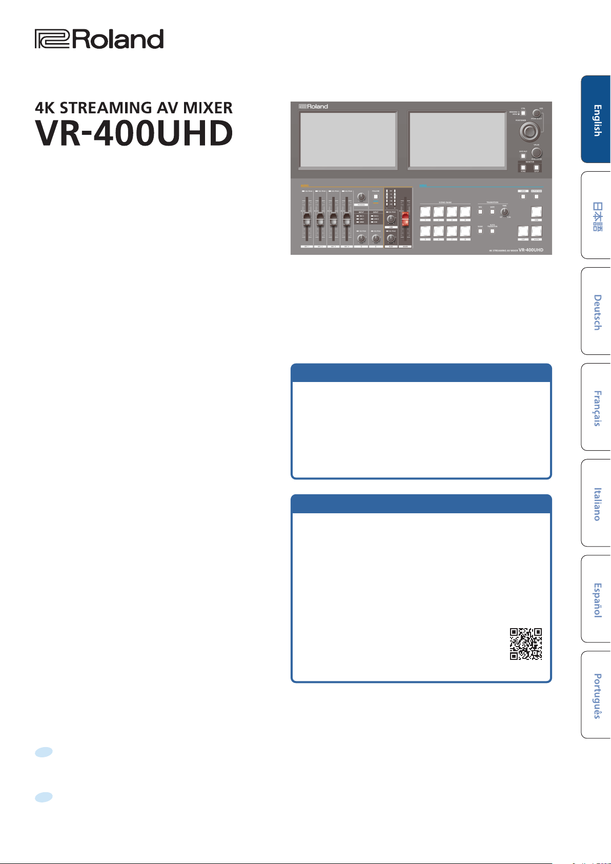
Startup Guide
Checking the Included Items
Check that all of the included items are present. If any of the
included items are missing, contact your dealer.
ÂVR-400UHD unit
ÂPower cord
ÂStartup Guide (this document)
PDF Manual (download from the Web)
Reference Manual
Contains more detailed explanations on operating this unit, a list of
menus and more.
Remote Control Guide
Contains information regarding the LAN/RS-232 and a list of control
commands.
Downloading
1. Enter the following URL in your computer.
https://proav.roland.com/manuals/
2. Choose “VR-400UHD” as the product name.
Before using the unit, ensure that its system program is at the most recent version. For information on available upgrades for the system program, see
the Roland website (https://proav.roland.com/).
You can check the system program version as follows: [SETUP] button Ó <System> tab in the Setup screen Ó <Version> Ó “System”.
Before using this unit, carefully read “IMPORTANT SAFETY INSTRUCTIONS” (inside front cover), “USING THE UNIT SAFELY” (p. 2), and “IMPORTANT NOTES”
(p. 4). After reading, keep the document(s) where it will be available for immediate reference.
© 2023 Roland Corporation
Page 2
ALWAYS OBSERVE THE FOLLOWING
USING THE UNIT SAFELY
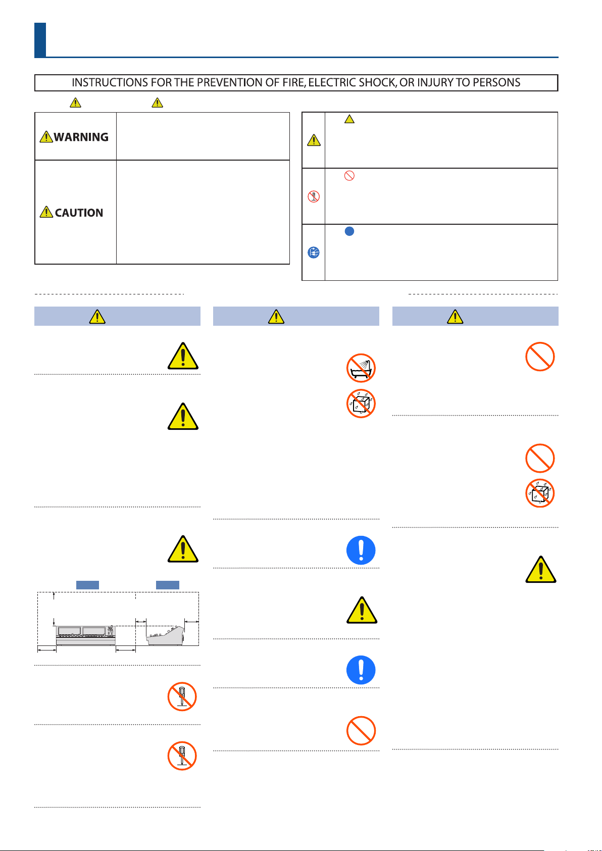
About WARNING and CAUTION Notices
Used for instructions intended to alert the
user to the risk of death or severe injury
should the unit be used improperly.
Used for instructions intended to alert the
user to the risk of injury or material
damage should the unit be used
improperly.
* Material damage refers to damage or
other adverse eects caused with
respect to the home and all its
furnishings, as well to domestic animals
or pets.
WARNING
Make sure that the power cord is grounded
Connect mains plug of this model
to a mains socket outlet with a
protective earthing connection.
To completely turn o power to the unit, pull out
the plug from the outlet
Even with the power switch turned
o, this unit is not completely
separated from its main source of
power. When the power needs to
be completely turned o, turn o the power
switch on the unit, then pull out the plug
from the outlet. For this reason, the outlet
into which you choose to connect the power
cord’s plug should be one that is within easy
reach and readily accessible.
Secure a sucient amount of space at the setup
location
Since this unit normally emits a
slight amount of heat, make sure to
secure sucient space around it, as
shown below.
Front Side
30 cm (12 in.)
or greater
20 cm (8 in.) or greater
5 cm (2 in.)
or greater
20 cm (8 in.) or greater
15 cm (6 in.)
or greater
Do not disassemble or modify by yourself
Do not carry out anything unless
you are instructed to do so in the
owner’s manual. Otherwise, you
risk causing malfunction.
Do not repair or replace parts by yourself
Be sure to contact your dealer, a
Roland service center, or an ocial
Roland dealer.
For a list of Roland service centers
and ocial Roland dealers, refer to the
Roland website.
Do not use or store in the following types of
locations
¹ Subject to temperature extremes
(e.g., direct sunlight in an
enclosed vehicle, near a heating
duct, on top of heat-generating
equipment); or are
¹ Damp (e.g., baths, washrooms,
on wet oors); or are
¹ Exposed to steam or smoke; or are
¹ Subject to salt exposure; or are
¹ Exposed to rain; or are
¹ Dusty or sandy; or are
¹ Subject to high levels of vibration and
shakiness; or are
¹ Placed in a poorly ventilated location.
Do not place in an unstable location
Otherwise, you risk injury as the
result of the unit toppling over or
dropping down.
Connect the power cord to an outlet of the
correct voltage
The unit should be connected to
a power supply only of the type
described as marked on the side
of unit.
Use only the supplied power cord
Use only the attached power cord.
Also, the supplied power cord must
not be used with any other device.
Do not bend the power cord or place heavy
objects on it
Otherwise, re or electric shock
may result.
About the Symbols
The symbol alerts the user to important instructions or
warnings.The specic meaning of the symbol is
determined by the design contained within the triangle. In
the case of the symbol at left, it is used for general
cautions, warnings, or alerts to danger.
The symbol alerts the user to items that must never be
carried out (are forbidden). The specic thing that must
not be done is indicated by the design contained within
the circle. In the case of the symbol at left, it means that
the unit must never be disassembled.
The symbol alerts the user to things that must be
carried out. The specic thing that must be done is
indicated by the design contained within the circle. In the
case of the symbol at left, it means that the power-cord
plug must be unplugged from the outlet.
WARNING
WARNING
Avoid extended use at high volume
Use of the unit at high volume
for extended periods of time may
cause hearing loss. If you ever
experience any hearing loss or
ringing in the ears, you should immediately
stop using the unit and consult a specialized
physician.
Do not allow foreign objects or liquids to enter
unit; never place containers with liquid on unit
Do not place containers containing
liquid (e.g., ower vases) on this
product. Never allow foreign
objects (e.g., ammable objects,
coins, wires) or liquids (e.g., water
or juice) to enter this product.
Doing so may cause short circuits,
faulty operation, or other malfunctions.
Turn o the unit if an abnormality or
malfunction occurs
In the following cases, immediately
turn o the power, remove the
power cord from the outlet, and
contact your dealer, a Roland
service center, or an ocial Roland dealer for
service.
¹ The power cord has been damaged; or
¹ If smoke or unusual odor occurs; or
¹ Objects have fallen into, or liquid has been
spilled onto the unit; or
¹ The unit has been exposed to rain (or
otherwise has become wet); or
¹ The unit does not appear to operate
normally or exhibits a marked change in
performance.
For a list of Roland service centers and ocial
Roland dealers, refer to the Roland website.
2
Page 3
USING THE UNIT SAFELY
WARNING
Be cautious to protect children from injury
Always make sure that an adult is
on hand to provide supervision and
guidance when using the unit in
places where children are present,
or when a child will be using the unit.
Do not drop or subject to strong impact
Otherwise, you risk causing
damage or malfunction.
Do not share an outlet with an unreasonable
number of other devices
Otherwise, you risk overheating
or re.
Do not use overseas
Before using the unit in overseas,
consult with your retailer, the
nearest Roland service center, or an
authorized Roland distributor.
For a list of Roland service centers and ocial
Roland dealers, refer to the Roland website.
Don’t block ventilation openings
Don’t allow the unit’s ventilation
openings to be blocked by a
newspaper, tablecloth, curtains, or
similar objects.
Don’t place burning objects on the unit
Don’t place any burning object
(such as a candle) on the unit.
Be aware of weather conditions
Use the apparatus in moderate
climates.
CAUTION
When disconnecting the power cord, grasp it by
the plug
To prevent conductor damage,
always grasp the power cord by its
plug when disconnecting it.
Periodically clean the power plug
An accumulation of dust or foreign
objects between the power plug
and the power outlet can lead to
re or electric shock.
At regular intervals, be sure to pull out the
power plug, and using a dry cloth, wipe away
any dust or foreign objects that may have
accumulated.
Disconnect the power plug whenever the unit
will not be used for an extended period of time
Fire may result in the unlikely event
that a breakdown occurs.
Route all power cords and cables in such a way as
to prevent them from getting entangled
Injury could result if someone were
to trip on a cable and cause the
unit to fall or topple.
Avoid climbing on top of the unit, or placing
heavy objects on it
Otherwise, you risk injury as the
result of the unit toppling over or
dropping down.
Never connect/disconnect a power plug if your
hands are wet
Otherwise, you could receive an
electric shock.
Disconnect all cords/cables before moving the
unit
Before moving the unit, disconnect
the power plug from the outlet,
and pull out all cords from external
devices.
Before cleaning the unit, disconnect the power
plug from the outlet
If the power plug is not removed
from the outlet, you risk receiving
an electric shock.
Whenever there is a threat of lightning,
disconnect the power plug from the outlet
If the power plug is not removed
from the outlet, you risk causing
malfunction or receiving an electric
shock.
Keep small items out of the reach of children
To prevent accidental ingestion
of the parts listed below, always
keep them out of the reach of small
children.
¹ Removable Parts
Cable holder (p. 8)
Screw (p. 8)
CAUTION
Handle the ground terminal carefully
If you remove the screw from the
ground terminal, be sure to replace
it; don’t leave it lying around where
it could accidentally be swallowed
by small children. When refastening the
screw, make that it is rmly fastened, so it
won’t come loose.
Take care not to get burned
The bottom, side, and rear may
become hot, so take care to avoid
burns.
Precautions concerning use of phantom power
supply
Always turn the phantom power o
when connecting any device other
than condenser microphones that
require phantom power. You risk
causing damage if you mistakenly supply
phantom power to dynamic microphones,
audio playback devices, or other devices that
don’t require such power. Be sure to check
the specications of any microphone you
intend to use by referring to the manual that
came with it.
(This instrument’s phantom power:
48 V DC, 10 mA Max)
3
Page 4

IMPORTANT NOTES
Power Supply
¹ Do not connect this unit to same electrical
outlet that is being used by an electrical
appliance that is controlled by an
inverter or a motor (such as a refrigerator,
washing machine, microwave oven, or
air conditioner). Depending on the way
in which the electrical appliance is used,
power supply noise may cause this unit
to malfunction or may produce audible
noise. If it is not practical to use a separate
electrical outlet, connect a power supply
noise lter between this unit and the
electrical outlet.
Placement
¹ Using the unit near power ampliers (or
other equipment containing large power
transformers) may induce hum. To alleviate
the problem, change the orientation of
this unit; or move it farther away from the
source of interference.
¹ This unit may interfere with radio and
television reception. Do not use this unit in
the vicinity of such receivers.
¹ Noise may be produced if wireless
communications devices, such as cell
phones, are operated in the vicinity of this
unit. Such noise could occur when receiving
or initiating a call, or while conversing.
Should you experience such problems, you
should relocate such wireless devices so
they are at a greater distance from this unit,
or switch them o.
¹ When moved from one location to
another where the temperature and/or
humidity is very dierent, water droplets
(condensation) may form inside the unit.
Damage or malfunction may result if you
attempt to use the unit in this condition.
Therefore, before using the unit, you must
allow it to stand for several hours, until the
condensation has completely evaporated.
¹ Depending on the material and
temperature of the surface on which you
place the unit, its rubber feet may discolor
or mar the surface.
¹ Do not place containers or anything else
containing liquid on top of this unit. Also,
whenever any liquid has been spilled on
the surface of this unit, be sure to promptly
wipe it away using a soft, dry cloth.
Repairs and Data
¹ Before sending the unit away for repairs, be
sure to make a backup of the data stored
within it; or you may prefer to write down
the needed information. Although we will
do our utmost to preserve the data stored
in your unit when we carry out repairs, in
some cases, such as when the memory
section is physically damaged, restoration
of the stored content may be impossible.
Roland assumes no liability concerning the
restoration of any stored content that has
been lost.
Maintenance
¹ Never use benzine, thinners, alcohol or
solvents of any kind, to avoid the possibility
of discoloration and/or deformation.
Additional Precautions
¹ Any data stored within the unit can be lost
as the result of equipment failure, incorrect
operation, etc. To protect yourself against
the irretrievable loss of data, be sure to
make a backup of the data stored within
it; or you may prefer to write down the
needed information.
¹ Roland assumes no liability concerning the
restoration of any stored content that has
been lost.
¹ Use a reasonable amount of care when
using the unit’s buttons, sliders, or other
controls; and when using its jacks and
connectors. Rough handling can lead to
malfunctions.
¹ Never strike or apply strong pressure to the
display.
¹ When disconnecting all cables, grasp the
connector itself—never pull on the cable.
This way you will avoid causing shorts, or
damage to the cable’s internal elements.
¹ A small amount of heat will radiate from the
unit during normal operation.
¹ To avoid disturbing others nearby, try to
keep the unit’s volume at reasonable levels.
¹ When disposing of the packing carton
or cushioning material in which this unit
was packed, you must observe the waste
disposal regulations that apply to your
locality.
¹ This unit allows you to switch images at
high speed. For some people, viewing such
images can cause headache, nausea, or
other discomfort. Do not use this unit to
create video that might cause these types
of health problems. Roland Corporation will
accept no responsibility for any such health
problems that may occur in yourself or in
viewers.
¹ Do not use connection cables that contain a
built-in resistor.
¹ This unit cannot be used to directly
connect to a network operated by
a telecommunications provider
(such as a mobile or landline-based
telecommunications company, an Internet
provider or the likes), including a public
wireless LAN. You must use a router or
similar equipment when connecting this
unit to the Internet.
¹ This document explains the specications of
the product at the time that the document
was issued. For the latest information, refer
to the Roland website.
Using External Memories
¹ Please observe the following precautions
when handling external memory devices.
Also, make sure to carefully observe all the
precautions that were supplied with the
external memory device.
– Do not remove the device while reading/
writing is in progress.
– To prevent damage from static electricity,
discharge all static electricity from your
person before handling the device.
Intellectual Property Right
¹ It is forbidden by law to make an audio
recording, video recording, copy or
revision of a third party’s copyrighted work
(musical work, video work, broadcast, live
performance, or other work), whether
in whole or in part, and distribute, sell,
lease, perform or broadcast it without the
permission of the copyright owner.
¹ Do not use this product for purposes
that could infringe on a copyright
held by a third party. We assume no
responsibility whatsoever with regard to
any infringements of third-party copyrights
arising through your use of this product.
¹ This product is using the open source
license (GPL/LGPL) software. You have the
right to acquire, modify and distribute the
source code for this open source license
software.
You can obtain the open source license
source code used in this product by
downloading it from the following website:
https://proav.roland.com/global/support/
¹ This product contains eParts integrated
software platform of eSOL Co.,Ltd. eParts is
a trademark of eSOL Co., Ltd. in Japan.
¹ Roland is an either registered trademark
or trademark of Roland Corporation in the
United States and/or other countries.
¹ Company names and product names
appearing in this document are registered
trademarks or trademarks of their
respective owners.
4
Page 5
Video Output: Overview
With the VR-400UHD, you can freely arrange multiple input videos and combine them into a single screen.
The combined video image is called a “scene”. You can switch between output videos for each scene. The scene preview is shown on the built-in
monitor, letting you check the preview while switching between scenes.
By preparing the scenes beforehand according to how the event proceeds, including the titles and captions as well as the screen layout, you can
smoothly operate this unit and produce a video with a live-action feel.
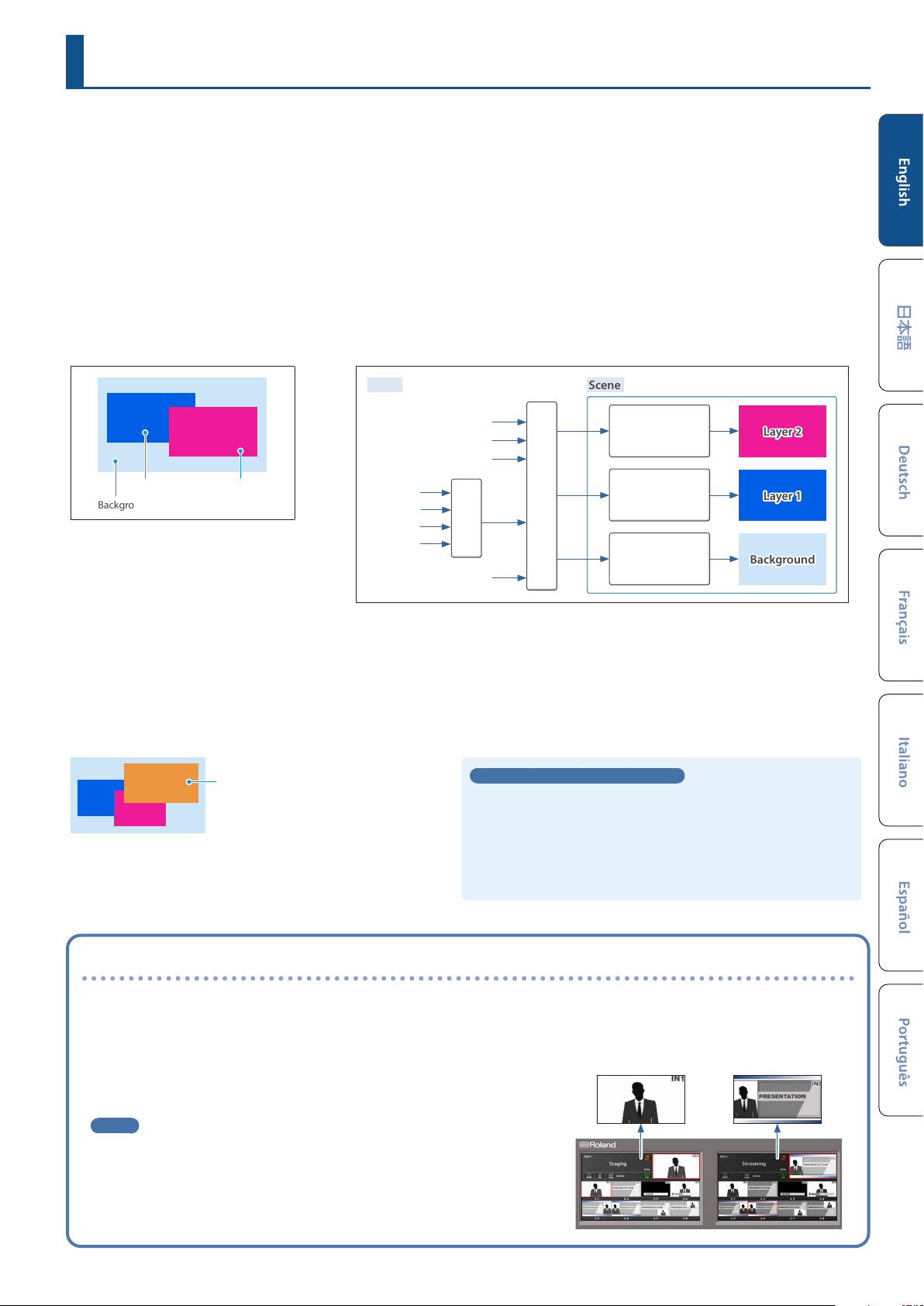
How the scenes are organized
Each scene is composed of three layers: a background layer, layer 1 and layer 2.
On each layer, you can display the input video signal from the HDMI 4K IN connector and the still images imported into this unit. You can also use
the crop function to cut out a certain part of the input video or still image.
It’s easy to create the screen layout you want just by enlarging or shrinking the layer window (display region) or by moving a window to the
desired location. You can also use the luminance key or chroma key on layers 1 and 2 to create a key composite video.
Scene organization Layer video
Layer 2Layer 1
Background
¹ The layer stacking order cannot be edited.
¹ You can choose whether to show or hide each
layer.
Input
HDMI 4-1
HDMI 4-2
HDMI 4-3
HDMI 4-4
HDMI 1
HDMI 2
HDMI 3
Selector
Still images (8)
Scene
Enlarge/shrink,
crop,
key composite
Enlarge/shrink,
crop,
key composite
Cross-point
Enlarge/shrink,
crop
Number of scenes that can be created
Each group of eight scenes is managed as a “bank”.
The VR-400UHD has eight banks, so you can create a total of 64 scenes (8 scenes × 8 banks).
DSK layer
A DSK layer is positioned in front of the scenes. The DSK layer lets you use DSK composition to add video or text (titles, captions, etc.) to a scene.
DSK layer
¹ Video on the DSK layer cannot be magnied or reduced.
¹ In addition to the DSK layer, you can composite the still image from the
logo layer, but only for video output from the 4K STREAMING port.
What is a DSK (downstream keyer)?
DSK is a function that lets you composite more video and text on top
of an already composited video.
This is called “downstream keyer” because the key is composited in
the downstream process.
For DSK composition, you can use a luminance key, a chroma key or a
still image (.png) with an alpha channel as the alpha key.
Outputting separate scenes to dierent output destinations (Dual mode)
There are two methods of outputting a scene: PGM/PST mode (factory setting)
and Dual mode.
For PGM/PST mode, only one scene is output. For Dual mode, two scenes can be
output independently.
This lets you select the optimal scene to match output destinations for dierent
purposes (example: for stage use and for streaming).
MEMO
¹ You can use two video buses, PGM 1 and PGM 2 in Dual mode. You can also
set the video bus assignment for each output connector.
Scene switching is always performed as a freeze-frame cut.
¹ The output method for scenes is set in System mode. For details on System
mode, refer to the Reference Manual (Roland website).
Output images in Dual mode
You can use the two built-in monitors on this unit to
select the scene to send to each video bus (PGM 1,
PGM 2).
5
Page 6
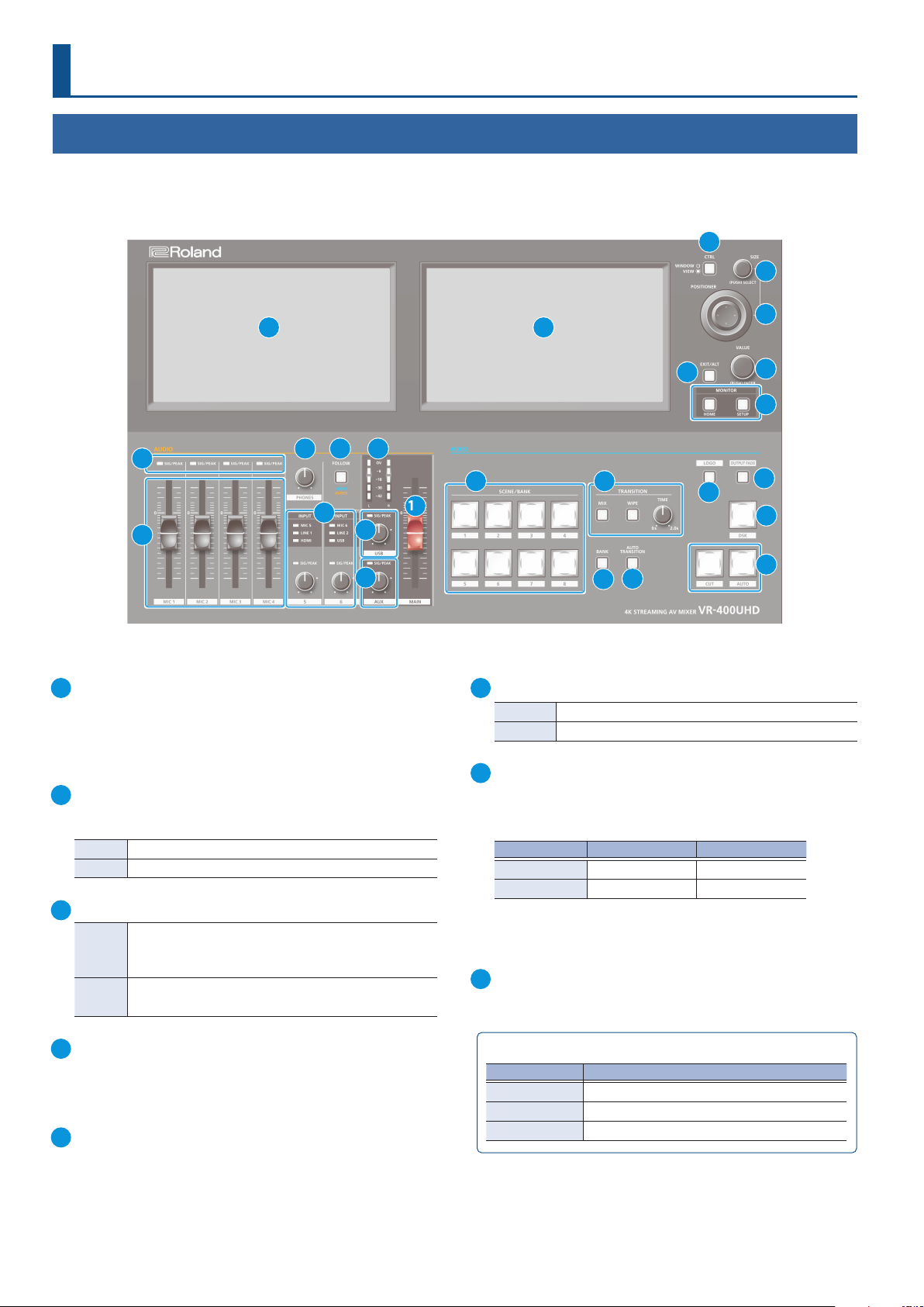
Panel Descriptions
Top Panel
* Do not block the cooling-fan intake and exhaust ports on the side panels. If the cooling-fan intake and exhaust ports are blocked, the internal
temperatures may rise, causing malfunctions due to excessive heat.
2
3
1
8
10 11 12
13
9
14
15
1
Monitor (touch panel)
This shows various information and settings screens, depending on
the operation.
You can operate the VR-400UHD by directly touching the screen.
* This device does not support multi-touch operations.
2
[CTRL] button
This selects what is controlled by the [SIZE] knob and the
[POSITIONER] stick.
Unlit Window size/position
Lit Zoom ratio/position of video in the window
3
[SIZE] knob
Adjusts the window size or the zoom ratio of the video
Turning
Pressing
inside the window.
* Use the [CTRL] button to select what is controlled.
Switches the Positioner popup between visible and hidden.
Select the layer to be controlled in the Positioner popup.
16
1
4
5
6
7
17
18
21
22
23
24
20
19
6
[VALUE] knob
Turning Edits the values on each settings screen.
Pressing Closes the numerical value popups and other controls.
7
MONITOR
[HOME] button
Shows the home screen on this unit’s monitor.
The home screen changes according to the system mode.
System mode Left monitor Right monitor
PGM/PST Audio mixer screen Multi-view screen
Dual PGM 1 screen PGM 2 screen
[SETUP] button
Shows the Setup screen on this unit’s monitor.
8
SIG/PEAK indicators (MIC 1–4)
Indicates the audio input levels for the MIC 1–4 jacks.
4
[POSITIONER] stick
Adjusts the window position or the position of the video inside the
window.
* Use the [CTRL] button to select what is controlled.
5
[EXIT/ALT] button
Exits the settings screen that’s currently displayed.
When on the multi-view screen, use this in combination with the
touch operations on the display to recall a specic function.
6
SIG/PEAK indicator
Indicator color Status
Red Volume is excessive (0 dB or higher)
Yellow Volume is suitable (-18 – -1 dB)
Green Volume is insucient (-42 – -19 dB)
Page 7
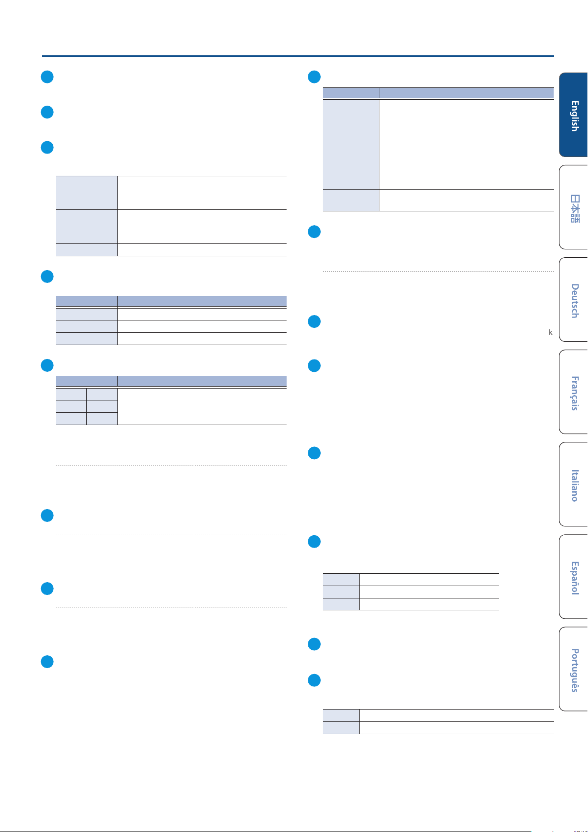
9
[MIC 1]–[MIC 4] faders
Adjusts the input level of the MIC 1–4 jacks.
10
[PHONES] knob
Adjusts the volume of the headphones.
11
[FOLLOW] button
Turns the “Video Follows Audio” function or the “Audio Follows Video”
function on/o.
Turns the Video Follows Audio function on.
Lit blue
Lit orange
Unlit O
12
MAIN level meter
Indicates the audio output level of the MAIN jacks.
Indicator color Status
Red Excessive (0 dB or higher)
Yellow Suitable (-18 – -1 dB)
Green Insucient (-42 – -19 dB)
The scene automatically switches in tandem with
the audio input.
Turns the Audio Follows Video function on.
The audio output automatically switches in
tandem with the scenes.
Panel Descriptions
17
SCENE/BANK [1]–[8] buttons
[BANK] button SCENE/BANK button function
These buttons select the scene to be output next
(the preset video).
The color of the button indicates the output
O (unlit)
On (lit)
18
TRANSITION
[MIX] [WIPE] button
Select the video transition eects (MIX or WIPE). The selected button
is lit.
[TIME] knob
Species the video transition time.
19
[BANK] button
When this is ON (lit), the SCENE/BANK [1]–[8] buttons function as bank
select buttons for the scene.
destination video bus.
Red: PGM bus
Green: PST bus
* This is how the unit works when the system
mode is set to “PGM/PST” (the factory setting).
Switches the scene bank. The selected button is lit
blue.
13
INPUT indicators (INPUT 5, 6)
Indicator Explanation
MIC 5 MIC 6
LINE 1 LINE 2
HDMI USB
Shows the audio source that’s controlled by the
[5] and [6] knobs.
SIG/PEAK indicators (INPUT 5, 6)
Indicates the input levels for the audio source that’s currently selected
(p. 6).
INPUT [5] [6] knobs
Adjusts the input level for the audio source that’s currently selected.
14
SIG/PEAK indicator (USB)
Indicates the audio output level of the 4K STREAMING port (p. 6).
[USB] knob
Adjusts the audio output level of the 4K STREAMING port.
15
SIG/PEAK indicator (AUX)
Indicates the audio output level of the AUX jacks (p. 6).
[AUX] knob
Adjusts the audio output level of the AUX jacks.
16
[MAIN] fader
Adjusts the audio output level of the MAIN jacks.
20
[AUTO TRANSITION] button
Turns the auto transition function on/o.
When this is turned ON (lit), the operation for the [AUTO] button is
automatically executed when you select the next scene to output
(preset video).
* This function is only enabled when the system mode is set to
“PGM/PST”.
21
[LOGO] button
Turns the LOGO layer composite on/o for the scene (video) that’s
output from the 4K STREAMING port (USB).
* Only still images saved in this unit can be used as sources for the
LOGO layer.
* The LOGO layer is composited regardless of the video bus you select
for the USB output.
22
[OUTPUT FADE] button
Fades the audio and PGM bus video in/out.
The [OUTPUT FADE] button indicates the fade status.
Lit
Blinking
Unlit
* The fade time is specied by the [TIME] knob setting.
23
[DSK] button
Turns DSK composition on/o for the PGM bus scene.
24
[CUT] [AUTO] buttons
Use these buttons to automatically output the PST bus scene to the
PGM bus.
[CUT] The scene switches instantly.
[AUTO] The scene switches with a transition eect applied.
Fade-out completed
Now fading-in/out
Normal output
* This is how the unit works when the system mode is set to “PGM/PST”
(the factory setting).
7
Page 8
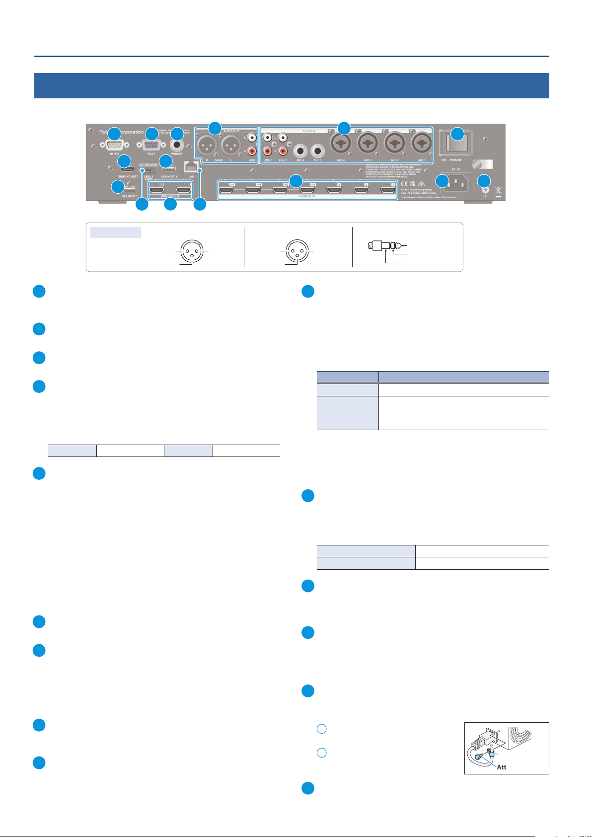
Panel Descriptions
2: HOT
3: COLD
2: HOT
1: GND
3: COLD
2: HOT
3: COLD
TIP: HOT
RING: COLD
SLEEVE: GND
2: HOT
1: GND
3: COLD
SLEEVE: GND
Rear Panel
* To prevent malfunction and equipment failure, always turn down the volume, and turn o all the units before making any connections.
1 2 3
4
7 8
9
11
10 12
Pin assignment MAIN jacks (XLR) MIC 1–4 jacks (XLR) MIC 1–6 jacks (TRS)
1: GND
1
RS-232 connector
You can connect this to a computer equipped with an RS-232
connector, and remotely control the VR-400UHD.
2
TALLY connector
Use this to connect to devices that have a tally indicator feature.
3
PHONES jack (Stereo 1/4-inch phone type)
Connect headphones.
4
MAIN, AUX jacks
These jacks output audio. Choose the jacks that are appropriate for
the connected devices.
You can congure what’s assigned to the audio bus (MAIN, AUX)
for each jack. With the factory settings, the bus assignments are as
follows.
MAIN jacks MAIN bus AUX jacks AUX bus
5
MIC 1–6, LINE 1, LINE 2 jacks
These jacks input audio. Choose the jacks that are appropriate for the
connected devices.
About phantom power
You can supply phantom power (+48 V) from the MIC 1–4 jacks (XLR).
Turn on phantom power when you’re using a condenser microphone
that requires phantom power.
Press the [HOME] button, access MIC 1–4 <EDIT> from the audio
mixer screen and then set “+48V” on the Audio Input Setup screen to
“Enable”.
* If you don’t need phantom power, be sure to turn phantom power o.
You risk causing damage if you mistakenly supply phantom power to
dynamic microphones or other devices that don’t require such power.
6
[POWER] switch
Turns the power on/o.
7
HDMI HD OUT connector
Outputs the same video as the built-in monitor. You can select which
video to output (either the video shown on the left monitor or on the
right). The same audio as the audio output from the MAIN connectors
is outputted.
* The output format is always HD (720/60p).
8
USB HOST 2 port
Connect a USB ash drive. Use this for backing up/restoring the
internal settings, or for loading still images.
9
USB HOST 1 port
Connect a USB ash drive. This is used to update the system program.
8
5
6
13 14 15
1: GND
10
4K STREAMING port (USB Type-C®)
Outputs video/audio to a computer that’s connected to this unit.
When the [LOGO] button on the top panel is on, you can overlay a still
image (a logo or image) on top of the scene to output.
This is also used to input audio played on your computer to the
VR-400UHD.
* To output the video, connect this port to a computer that supports
USB 3.0 or 3.2 Gen 2. USB 2.0 only supports audio.
USB standard Limitations
USB 2.0 Video cannot be output. Only audio is output.
USB 3.0
(USB 3.2 GEN 1)
USB 3.2 GEN 2 None
* If you connect via an extension cable or a USB hub, the computer
might not recognize the VR-400UHD.
* Do not use a USB cable that is designed only for charging a device.
Charge-only cables cannot transmit data.
11
HDMI 4K OUT 1, 2 connectors
These connectors output video and audio.
The video output from each connector diers depending on the
system mode and video bus settings. With the factory settings, the
video bus assignments are as follows.
HDMI 4K OUT 1 connector PGM bus (program video)
HDMI 4K OUT 2 connector PST bus (preview video)
12
LAN port
Connect a controlling device and use a command-line app such as
Terminal or the command prompt to remotely control the VR-400UHD
over a network.
13
HDMI 4K IN 1–3, 4-1–4-4 connectors
These connectors input video and audio. Select one input of the HDMI
4K IN 4-1 through 4-4 connectors, which you can use as a scene or DSK
source.
The input format is automatically recognized.
14
AC IN jack
Connect the included power cord.
You can fasten the power cord with the cable holder to keep it in place.
Loosen the attaching screw and
1
remove the cable holder.
Reattach the cable holder with the
2
power cord fastened underneath,
and tighten the screw back in place.
15
Ground terminal
Connect this to an external earth or ground if necessary.
TIP: HOT
RING: COLD
Video sizes greater than 1080p cannot be output.
Cable holder
Attaching screw
Page 9
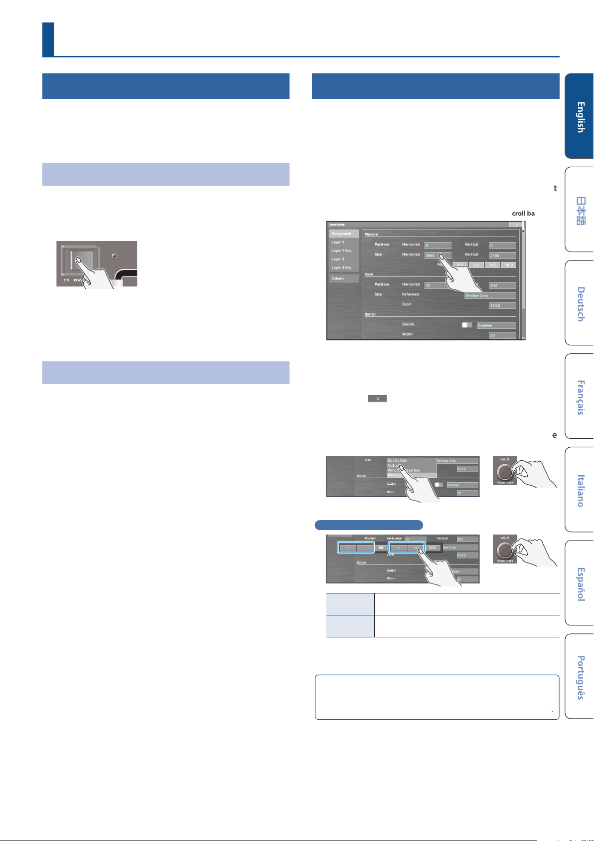
Basic Operations
Turning the Power On/O
* Before turning the unit on/o, always be sure to turn the volume
down. Even with the volume turned down, you might hear some
sound when switching the unit on/o. However, this is normal
and does not indicate a malfunction.
Turning the Power On
1. Make sure that all devices are powered-o.
2. Turn on the [POWER] switch on the VR-400UHD to turn
on the power.
3. Turn on the power in the order of source devices
output devices.
Turning the Power O
1. Turn o the power in the order of output devices
source devices.
Ó
Ó
Screen (Touch Panel) Operations
Here’s how to congure the video/audio settings along with the
settings for this unit by operating the screen.
1. Press the [HOME] button or [SETUP] button.
The home screen or SETUP screen appears.
2. Touch the screen to select the setting item that you want
to edit.
Scroll bar
* When the scroll bar is shown:
Touch and drag up/down on the screen to scroll it.
3. Repeat step 2 as needed.
Touching < > on the screen or pressing the [EXIT/ALT]
button returns you to the previous screen.
2. Turn o the [POWER] switch on the VR-400UHD to turn
o the power.
* If you need to turn o the power completely, rst turn o the unit,
then unplug the power cord from the power outlet.
Refer to “To completely turn o power to the unit, pull out the
plug from the outlet” (p. 2).
4. Touch the screen or turn the [VALUE] knob to change the
setting value.
Changing numerical values
INIT
NUM
Saving your settings
The settings are saved to this unit if you don’t operate the unit for
four seconds, or if you press the [HOME] button to close the screen.
Returns the current setting item you’re setting to its
default value.
Displays the numerical value popup. You can enter a
numerical value by touching the number keys.
9
Page 10
Switching Between Scenes
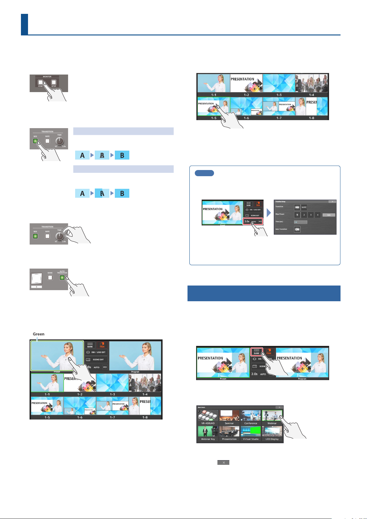
This explains how to switch between scenes in PGM/PST mode (p. 5), which is the factory setting.
1. Press the [HOME] button.
The audio mixer screen is shown on the left
monitor, and the multi-view screen is shown
on the right monitor.
2. Press the [MIX] or [WIPE] button to select the transition
eect.
Mix
The two videos are mixed as the transition
occurs.
Wipe
The next video moves across to replace the
original video.
3. Use the [TIME] knob to set the video transition time
(0.0–2.0 sec).
6. Touch the scene to output on the multi-view screen.
The program output scene changes.
* You can also press the SCENE/BANK [1]–[8] buttons to switch
between scenes.
MEMO
¹ When you touch the transition eect area on the multi-view
screen, the Transition Setup window appears, where you can
edit the transition pattern for the wipe eect and so on.
4. Press the [AUTO TRANSITION] button to turn the auto-
transition function on (the button lights up).
Auto-transition is a function that automatically switches between
scenes when you select the scene (preset video) to be output next.
5. Touch the preset area in the multi-view screen.
Green border
¹ You can also use the [CUT] and [AUTO] buttons to manually
switch between scenes without using the auto-transition
function.
Switching the Scene Bank
Each group of eight scenes is managed as a “bank”. The VR-400UHD
features eight banks.
This explains how to switch between banks on the multi-view screen.
1. Touch <BANK> on the multi-view screen.
The Bank Select window appears.
2. Touch the bank you want to use.
A green border appears around the preset area.
While the green border is shown, you can select the next scene
(preset video) from scenes 1–8 to output.
10
This switches to the new bank.
3. Touch < > to close the Bank Select window.
Page 11
Editing the Scenes
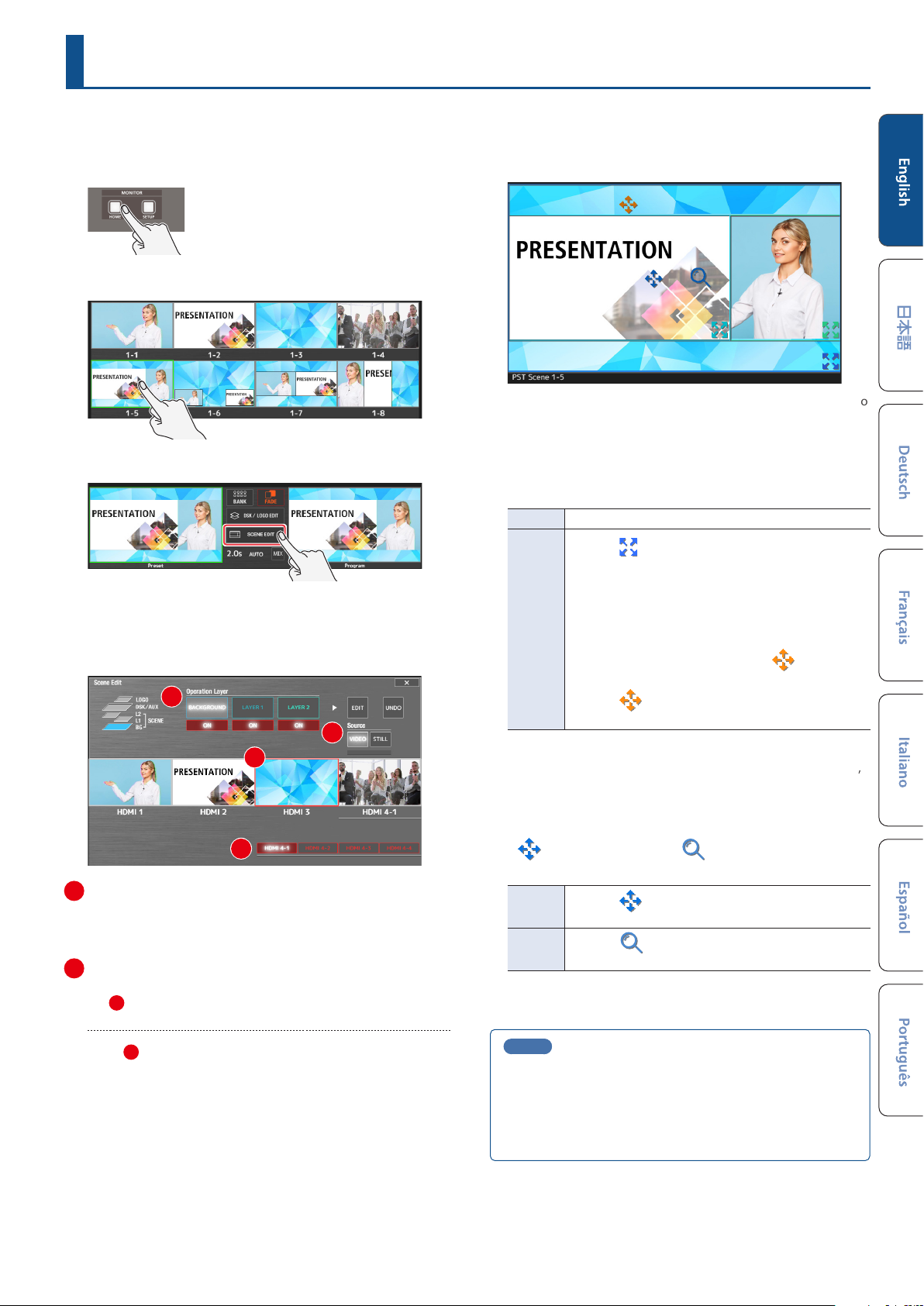
This section explains the basic methods of editing a scene.
1. Press the [HOME] button.
The audio mixer screen is shown on the left
monitor, and the multi-view screen is shown
on the right monitor.
2. Touch the scene to edit on the multi-view screen.
3. Touch <SCENE EDIT>.
The Scene Edit screen appears on the left and right monitors.
4. Edit the scene on the Scene Edit screen.
(Right-side screen)
1
2
3
(Left-side screen)
Square boxes (layer windows) are shown on the left-side screen to
represent each layer’s position and size.
The layer that’s selected in the right-side screen in “Operation
Layer” is targeted for editing.
Layer window operations
Position Drag a layer window to move it.
Drag the
corner of a layer window to enlarge or shrink the
window.
Size
* You can also change the position and size of layer windows that
aren’t targeted for editing. For the parts of windows that overlap,
the layer targeted for editing is given priority.
Moving only one side of a window
When you touch one side of a layer window in a layer
that’s targeted for editing, an orange
(edge icon) appears.
Drag the
targeted window.
symbol (size icon) at the bottom right
symbol
symbol to move only one side of the
4
1
Select the layer to edit (operation layer)
Touch the layer to edit.
Touch <ON> to show or hide the respective layer.
2
Select the input video (source)
Touch and select <VIDEO> to view the input video signals from
the 3 HDMI 4K IN connectors. Touch the input video to select
which video you want to assign to the layer.
4
Touch
input video signals.
* A black screen is shown when switching between video signals.
* The input video for HDMI 4 uses the same settings as VR-400UHD.
You can’t congure the settings for each layer or scene.
<HDMI 4-1>–<HDMI 4-4> to switch between the HDMI 4
Video operations inside a layer window
symbol (view icon) and a symbol (zoom icon) are
A
shown in the windows of layers that are targeted for editing.
Position
Size
MEMO
¹ Since the changes you make to a scene are automatically
saved, you don’t need to do anything to save them.
¹ When you touch <UNDO> on the right-hand screen before
the Scene Edit screen closes, you can revert the scene to how
it was before editing.
Drag the
video inside the layer window.
Drag the
enlarge or shrink the video inside the layer window.
symbol to adjust the position of the
symbol (zoom icon) up and down to
11
Page 12

 Loading...