

Page 1
Data List
Copyright © 2016 ROLAND CORPORATION
Page 2
Contents
DRUM KIT . . . . . . . . . . . . . . . . . . . . . . . . . . . . . . . . . . . . . . . . . . . . . . . . . 3
DRUM KIT Screen . . . . . . . . . . . . . . . . . . . . . . . . . . . . . . . . . . . . . . . . 3
KIT SETTINGS . . . . . . . . . . . . . . . . . . . . . . . . . . . . . . . . . . . . . . . . . . . 3
KIT SETTINGS 1 (page 1) . . . . . . . . . . . . . . . . . . . . . . . . . . . . . 3
KIT SETTINGS 2 (page 2) . . . . . . . . . . . . . . . . . . . . . . . . . . . . . 4
PAD CONTROL (page 3) . . . . . . . . . . . . . . . . . . . . . . . . . . . . . 4
PAD MIDI (page 4) . . . . . . . . . . . . . . . . . . . . . . . . . . . . . . . . . . 5
KIT CUSTOMIZE . . . . . . . . . . . . . . . . . . . . . . . . . . . . . . . . . . . . . . . . . . . 6
INSTRUMENT . . . . . . . . . . . . . . . . . . . . . . . . . . . . . . . . . . . . . . . . . . . 6
INSTRUMENT (page 1) . . . . . . . . . . . . . . . . . . . . . . . . . . . . . . 6
MIC POSITION (page 2) . . . . . . . . . . . . . . . . . . . . . . . . . . . . . 9
TRANSIENT (page 3) . . . . . . . . . . . . . . . . . . . . . . . . . . . . . . . . 9
SUB INST (page 4) . . . . . . . . . . . . . . . . . . . . . . . . . . . . . . . . . . 10
AMBIENCE . . . . . . . . . . . . . . . . . . . . . . . . . . . . . . . . . . . . . . . . . . . . . . 11
AMBIENCE LEVEL (page 1) . . . . . . . . . . . . . . . . . . . . . . . . . . . 11
ROOM (page 2) . . . . . . . . . . . . . . . . . . . . . . . . . . . . . . . . . . . . 11
REVERB (page 3) . . . . . . . . . . . . . . . . . . . . . . . . . . . . . . . . . . . 12
STEREO ENHANCER (page 4) . . . . . . . . . . . . . . . . . . . . . . . . . 12
MIXER . . . . . . . . . . . . . . . . . . . . . . . . . . . . . . . . . . . . . . . . . . . . . . . . . . 13
MIXER VOLUME (page 1) . . . . . . . . . . . . . . . . . . . . . . . . . . . . 13
PAD EQ (page 2) . . . . . . . . . . . . . . . . . . . . . . . . . . . . . . . . . . . 14
PAD COMP (page 3) . . . . . . . . . . . . . . . . . . . . . . . . . . . . . . . . 14
MULTI EFFECT (MFX) (page 4) . . . . . . . . . . . . . . . . . . . . . . . . 15
MASTER COMP (page 5) . . . . . . . . . . . . . . . . . . . . . . . . . . . . . 16
MASTER EQ (page 6) . . . . . . . . . . . . . . . . . . . . . . . . . . . . . . . . 17
USER SAMPLE . . . . . . . . . . . . . . . . . . . . . . . . . . . . . . . . . . . . . . . . . . . . . 18
SAMPLE LIST. . . . . . . . . . . . . . . . . . . . . . . . . . . . . . . . . . . . . . . 18
SONG . . . . . . . . . . . . . . . . . . . . . . . . . . . . . . . . . . . . . . . . . . . . . . . . . . . . . 19
SONG (page 1) . . . . . . . . . . . . . . . . . . . . . . . . . . . . . . . . . . . . . 19
SONG INFO (page 2) . . . . . . . . . . . . . . . . . . . . . . . . . . . . . . . . 19
SET LIST. . . . . . . . . . . . . . . . . . . . . . . . . . . . . . . . . . . . . . . . . . . . . . . . . . . 20
SETUP . . . . . . . . . . . . . . . . . . . . . . . . . . . . . . . . . . . . . . . . . . . . 20
CLICK . . . . . . . . . . . . . . . . . . . . . . . . . . . . . . . . . . . . . . . . . . . . . . . . . . . . . 21
TRIGGER . . . . . . . . . . . . . . . . . . . . . . . . . . . . . . . . . . . . . . . . . . . . . . . . . . 22
TRIG BASIC (page 1) . . . . . . . . . . . . . . . . . . . . . . . . . . . . . . . . 22
TRIG ADVANCED (page 2) . . . . . . . . . . . . . . . . . . . . . . . . . . . 24
TRIG MONITOR (page 3) . . . . . . . . . . . . . . . . . . . . . . . . . . . . . 26
Multi-Eect Parameters . . . . . . . . . . . . . . . . . . . . . . . . . . . . . . . . . . . 34
DELAY . . . . . . . . . . . . . . . . . . . . . . . . . . . . . . . . . . . . . . . . . . . . 35
TAPE ECHO . . . . . . . . . . . . . . . . . . . . . . . . . . . . . . . . . . . . . . . . 35
REVERSE DELAY . . . . . . . . . . . . . . . . . . . . . . . . . . . . . . . . . . . . 35
3TAP PAN DELAY . . . . . . . . . . . . . . . . . . . . . . . . . . . . . . . . . . . 35
OD0DELAY . . . . . . . . . . . . . . . . . . . . . . . . . . . . . . . . . . . . . . 36
DS0DELAY . . . . . . . . . . . . . . . . . . . . . . . . . . . . . . . . . . . . . . . 36
CHORUS . . . . . . . . . . . . . . . . . . . . . . . . . . . . . . . . . . . . . . . . . . 36
SPACE-D . . . . . . . . . . . . . . . . . . . . . . . . . . . . . . . . . . . . . . . . . . 36
OD0CHORUS . . . . . . . . . . . . . . . . . . . . . . . . . . . . . . . . . . . . 36
DS0CHORUS . . . . . . . . . . . . . . . . . . . . . . . . . . . . . . . . . . . . . 36
PHASER A . . . . . . . . . . . . . . . . . . . . . . . . . . . . . . . . . . . . . . . . . 37
PHASER B . . . . . . . . . . . . . . . . . . . . . . . . . . . . . . . . . . . . . . . . . 37
STEP PHASER . . . . . . . . . . . . . . . . . . . . . . . . . . . . . . . . . . . . . . 37
FLANGER . . . . . . . . . . . . . . . . . . . . . . . . . . . . . . . . . . . . . . . . . . 37
REVERB . . . . . . . . . . . . . . . . . . . . . . . . . . . . . . . . . . . . . . . . . . . 38
LONG REVERB . . . . . . . . . . . . . . . . . . . . . . . . . . . . . . . . . . . . . 38
SUPER FILTER . . . . . . . . . . . . . . . . . . . . . . . . . . . . . . . . . . . . . . 38
FILTER+DRIVE . . . . . . . . . . . . . . . . . . . . . . . . . . . . . . . . . . . . . . 38
AUTO WAH . . . . . . . . . . . . . . . . . . . . . . . . . . . . . . . . . . . . . . . . 39
OD/DS0TWAH . . . . . . . . . . . . . . . . . . . . . . . . . . . . . . . . . . . 39
LOFI COMPRESS . . . . . . . . . . . . . . . . . . . . . . . . . . . . . . . . . . . . 39
DISTORTION . . . . . . . . . . . . . . . . . . . . . . . . . . . . . . . . . . . . . . . 39
OVERDRIVE . . . . . . . . . . . . . . . . . . . . . . . . . . . . . . . . . . . . . . . . 39
SATURATOR . . . . . . . . . . . . . . . . . . . . . . . . . . . . . . . . . . . . . . . 39
T-SCREAM . . . . . . . . . . . . . . . . . . . . . . . . . . . . . . . . . . . . . . . . . 40
BIT CRUSHER . . . . . . . . . . . . . . . . . . . . . . . . . . . . . . . . . . . . . . 40
ISOLATOR . . . . . . . . . . . . . . . . . . . . . . . . . . . . . . . . . . . . . . . . . 40
RING MODULATOR . . . . . . . . . . . . . . . . . . . . . . . . . . . . . . . . . 40
PITCH SHIFTER . . . . . . . . . . . . . . . . . . . . . . . . . . . . . . . . . . . . . 40
AUTO PAN . . . . . . . . . . . . . . . . . . . . . . . . . . . . . . . . . . . . . . . . . 40
Drum Kit List . . . . . . . . . . . . . . . . . . . . . . . . . . . . . . . . . . . . . . . . . . . . . . 41
Instrument List . . . . . . . . . . . . . . . . . . . . . . . . . . . . . . . . . . . . . . . . . . . 42
Song List . . . . . . . . . . . . . . . . . . . . . . . . . . . . . . . . . . . . . . . . . . . . . . . . . . 46
Drum Kit Parameter Structure . . . . . . . . . . . . . . . . . . . . . . . . . . . . 47
Block Diagram . . . . . . . . . . . . . . . . . . . . . . . . . . . . . . . . . . . . . . . . . . . . 48
SETUP . . . . . . . . . . . . . . . . . . . . . . . . . . . . . . . . . . . . . . . . . . . . . . . . . . . . 27
OUTPUT . . . . . . . . . . . . . . . . . . . . . . . . . . . . . . . . . . . . . . . . . . . . . . . . 27
PAD OUTPUT (page 1) . . . . . . . . . . . . . . . . . . . . . . . . . . . . . . 27
OTHER OUTPUT (page 2) . . . . . . . . . . . . . . . . . . . . . . . . . . . . 28
OUTPUT ROUTING (page 3) . . . . . . . . . . . . . . . . . . . . . . . . . . 29
USB AUDIO . . . . . . . . . . . . . . . . . . . . . . . . . . . . . . . . . . . . . . . . . . . . . 30
OPTION . . . . . . . . . . . . . . . . . . . . . . . . . . . . . . . . . . . . . . . . . . . . . . . . 30
CONTROL. . . . . . . . . . . . . . . . . . . . . . . . . . . . . . . . . . . . . . . . . . . . . . . 31
MIDI . . . . . . . . . . . . . . . . . . . . . . . . . . . . . . . . . . . . . . . . . . . . . . . . . . . 32
AUTO OFF . . . . . . . . . . . . . . . . . . . . . . . . . . . . . . . . . . . . . . . . . . . . . . 33
INFO . . . . . . . . . . . . . . . . . . . . . . . . . . . . . . . . . . . . . . . . . . . . . . . . . . . 33
2
Page 3
DRUM KIT
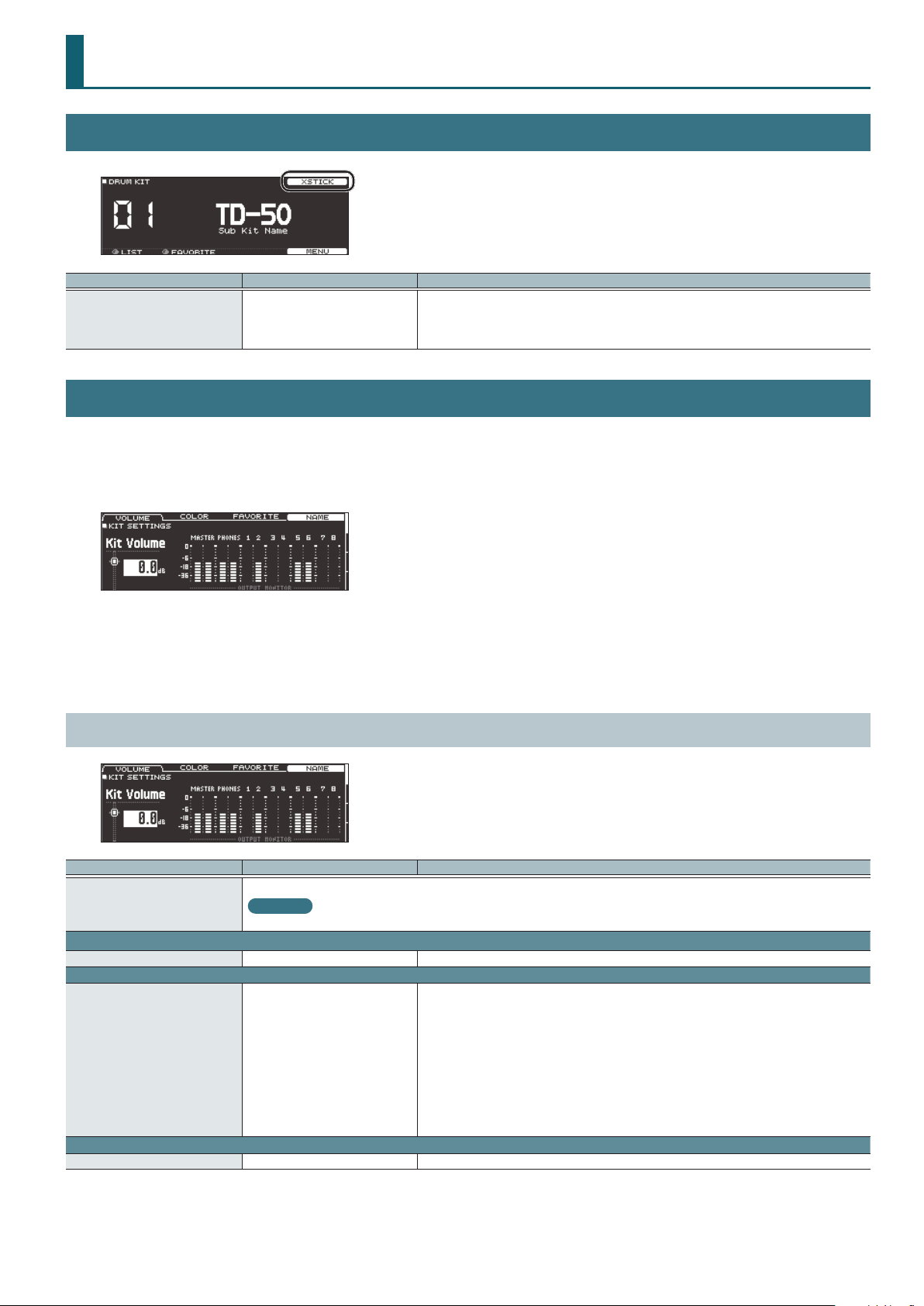
DRUM KIT Screen
Parameter Value Explanation
Species whether a snare pad produces the cross-stick sound (ON) or not (OFF).
XSTICK OFF, ON
KIT SETTINGS
1. Press the [KIT] button.
1. Press the [F5] (MENU) button.
The menu screen appears.
If the trigger input of a pad that supports both cross-stick technique and digital connection (such
as the PD-140DS) is assigned to a snare, cross-stick playing is always possible. In this case, the
screen does not show the XSTICK icon.
2. Use the PAGE [UP] [DOWN] buttons to access the editing screen.
3. Use cursor buttons to select a parameter, and use the [–] [+] buttons or the dial to edit the value.
4. Press the [KIT] button to return to the DRUM KIT screen.
KIT SETTINGS 1 (page 1)
Parameter Value Explanation
Edits the name of the drum kit.
[F4] button
VOLUME tab
Kit Volume -INF–+6.0 dB Drum kit volume
COLOR tab
Kit Color
FAVORITE tab
Favorite OFF, ON Registers (ON)/de-registers (OFF) the drum kit in favorites.
Reference
For details on how to assign a name, refer to “Renaming a Drum Kit” in the “Reference Manual” (PDF).
1: WHITE
2: RED
3: GREEN
4: BLUE
5: PINK
6: PURPLE
7: ORANGE
8: YELLOW
9: EMERALD
10: RAINBOW
Use the [KIT] button or [R1]–[R3] knobs to specify the illumination color.
3
Page 4
DRUM KIT
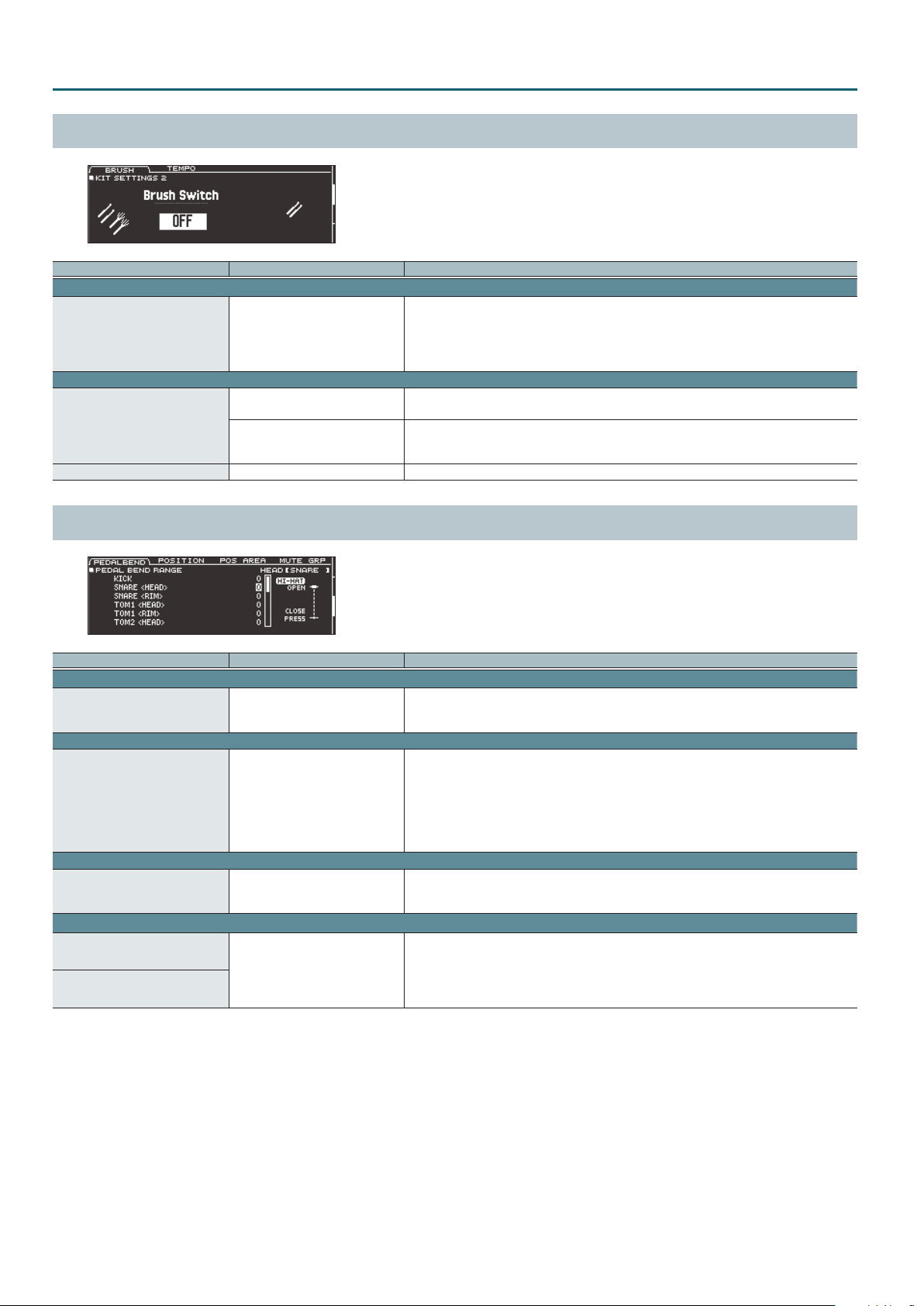
KIT SETTINGS 2 (page 2)
Parameter Value Explanation
BRUSH tab
Species whether you’re performing with sticks (OFF) or brushes (ON).
Brush Switch OFF, ON
KIT TEMPO tab
OFF
Kit Tempo
ON
Tempo 20–260 Tempo specied for each drum kit
If this is “ON,” you can perform by scraping (sweeping) the brushes.
* This is supported starting with program version 1.05. Refer to the Roland website for the latest
information.
http://www.roland.com/support/
Use a common tempo (p. 21) for the entire TD-50.
The tempo does not change when you switch drum kits.
Use the tempo that is specied by each drum kit.
The click tempo and the tempo of tempo-synchronized eects can be individually specied for
each drum kit.
PAD CONTROL (page 3)
Parameter Value Explanation
PEDALBEND tab
Species the amount of pitch change that occurs according to the depth to which you press the
Pedal Bend Range -24–0–+24
POSITION tab
Position Control*1 OFF, ON
POS AREA tab
Position Area*1 INSIDE -5–DEFAULT– OUTSIDE +5
MUTE GRP tab
MUTE SEND
– (OFF), 1–8
MUTE RECEIVE
*1 This supports the following trigger inputs.
5 SNARE
5 TOM1–4
5 The bow (head) of RIDE
5 AUX1–4
* Depending on the pad that is connected or the instrument that is selected, there might be cases in which this has no eect.
hi-hat pedal.
You can set this for each pad (head and rim separately) in semitone units.
Turns on/o tonal changes that occur depending on your strike location or the nuances of your rim
shots.
You can set this for the snare (head, rim), tom (head, rim), ride (bow), and AUX (head, rim) trigger
inputs.
Head: Strike position
Rim: Rim shot nuance
Bow: Strike position
Species the striking area for the head or rim.
“INSIDE” settings make it easier to play notes toward the inside; “OUTSIDE” settings make it easier to
play toward the outside.
Specify the mute group number.
When you strike the pad of the number specied in MUTE SEND, the sound of the pad assigned to
the same number in MUTE RECEIVE is muted.
* Even if you specify the same number in MUTE SEND and MUTE RECEIVE for the same location
(e.g., head or rim) of the same pad, muting does not occur.
4
Page 5
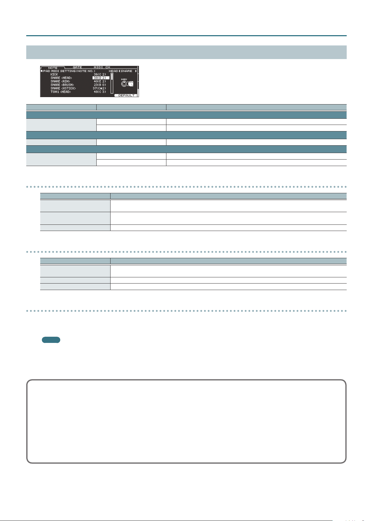
PAD MIDI (page 4)
Parameter Value Explanation
NOTE tab
Note No.
GATE tab
Gate Time 0.1– 8.0 s Duration of the note transmitted by each pad
MIDI CH tab
MIDI Channel
MIDI note numbers transmitted and received by the hi-hat
Item Explanation
HI-HAT OPEN <BOW>
HI-HAT OPEN <EDGE>
HI-HAT CLOSE <BOW>
HI-HAT CLOSE <EDGE>
HI-HAT PEDAL MIDI note number transmitted and received by pedal hi-hat
0(C -)–127(G 9) MIDI note number transmitted and received by each pad
OFF Note messages are not transmitted or received
CH1–CH16 MIDI channel on which each pad transmits or receives note messages or control change messages
GLOBAL Transmitted and received on the transmit/receive channel specied in SETUP (p. 32)
MIDI note number transmitted and received by open hi-hat (bow, edge)
MIDI note number transmitted and received by closed hi-hat (bow, edge)
DRUM KIT
MIDI note numbers transmitted and received by the snare
Parameter Explanation
SNARE <HEAD>
SNARE <RIM>
SNARE <BRUSH> MIDI note number transmitted and received by brush sweep
SNARE <XSTICK> MIDI note number transmitted and received by cross stick
MIDI note number transmitted and received by head shot and rim shot
When setting multiple pads to the same note number
When playing the internal sound generator of the TD-50, if an incoming note number is assigned to more than one pad, that note plays the
instrument of the pad with the lowest trigger input number. If the same note number is assigned to both the head and the rim, the head instrument
is sounded.
MEMO
An asterisk (*) appears at the right of the note number for trigger inputs that are not sounded.
Example:
Note number “38 (D 2)” is set for the head and rim of trigger input 2 SNARE and the head of trigger input 3 TOM 1. In this case, when note number 38
(D2) is received, the instrument assigned to the head of trigger input 2 SNARE is played.
About the gate time
Percussion sound modules normally produce sound only in response to “Note on” messages, and ignore “Note o” messages. However generalpurpose sound modules or samplers do receive the note-o messages that are transmitted and respond by turning o the sound.
Since gate time is normally not necessary for a percussion sound module, this is set to the minimum value when the unit is shipped from the
factory. If a note-o message is received while the sound module has this setting, it is received as an extremely brief note that has almost no
time to be heard, and is nearly inaudible. (Alternatively, it is possible that this could be heard as an unwanted noise.) To avoid this, specify the
note duration of the MIDI performance data that is produced when you strike each pad.
* If the same note number is sounded again in an overlapping manner, a note-o is transmitted before transmitting note-on, even if it is
within the gate time.
5
Page 6
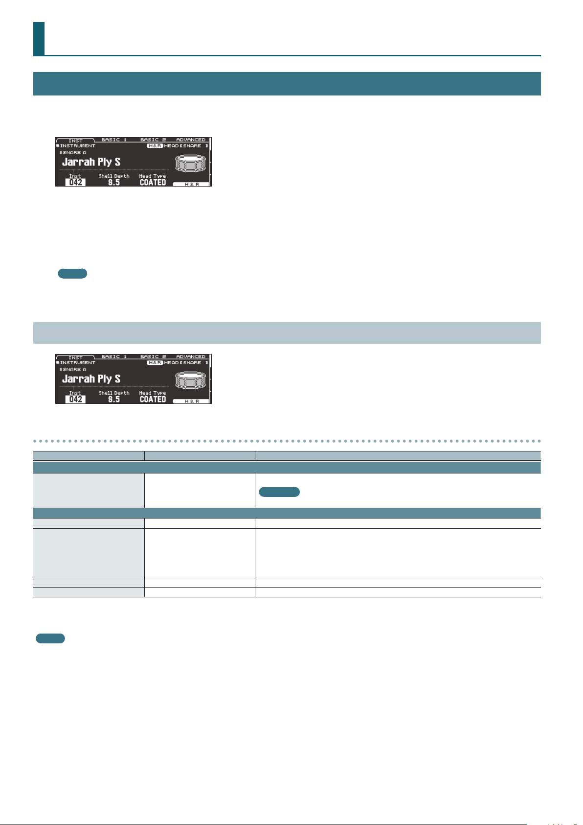
KIT CUSTOMIZE
INSTRUMENT
1. Press the [INSTRUMENT] button.
The INSTRUMENT screen appears.
2. Select the pad that you want to edit.
3. Use the PAGE [UP] [DOWN] buttons and function buttons to select the item that you want to edit.
* The parameters that you can edit depend on the pad and instrument.
4. Use cursor buttons to select a parameter, and use the [–] [+] buttons or the dial to edit the value.
MEMO
For some parameters, you can also use the rotary knobs to edit the value.
5. Press the [KIT] button to return to the DRUM KIT screen.
INSTRUMENT (page 1)
Parameters that can be edited for each instrument
Parameter Value Explanation
INST tab
Inst
ADVANCED tab
Pitch -4800–4800 Instrument pitch (units of one cent)
Pitch Sweep*1 -100–100
Decay*1 1–100 Length of decay
Dynamic Enhancer Sw*1, *2 OFF, ON Species whether the sense of strong strikes is enhanced (ON) or not enhanced (OFF).
*1 If a user sample is assigned to the instrument, you can’t specify Dynamic Enhancer Sw. Also, if the user sample’s Play Type (p. 18) is set to “LOOP ALT,” the Pitch Sweep and Decay
have no eect.
*2 For some instruments, this cannot be set.
MEMO
If you press the [F5] (H&R) button to turn it “ON,” you can simultaneously make settings for the head area and rim area, etc.
001– (preset)
U001–U500 (user sample)
Instrument number
Reference
For more about instruments, refer to “Instrument List” (p. 42).
After the sound begins, the pitch gradually rises (falls).
Positive (+) values make the pitch start high and then fall; negative (-) values make the pitch start
low and then rise.
Larger values produce greater change.
* In some cases, changing the Pitch setting by a large amount might limit the Pitch Sweep eect.
6
Page 7
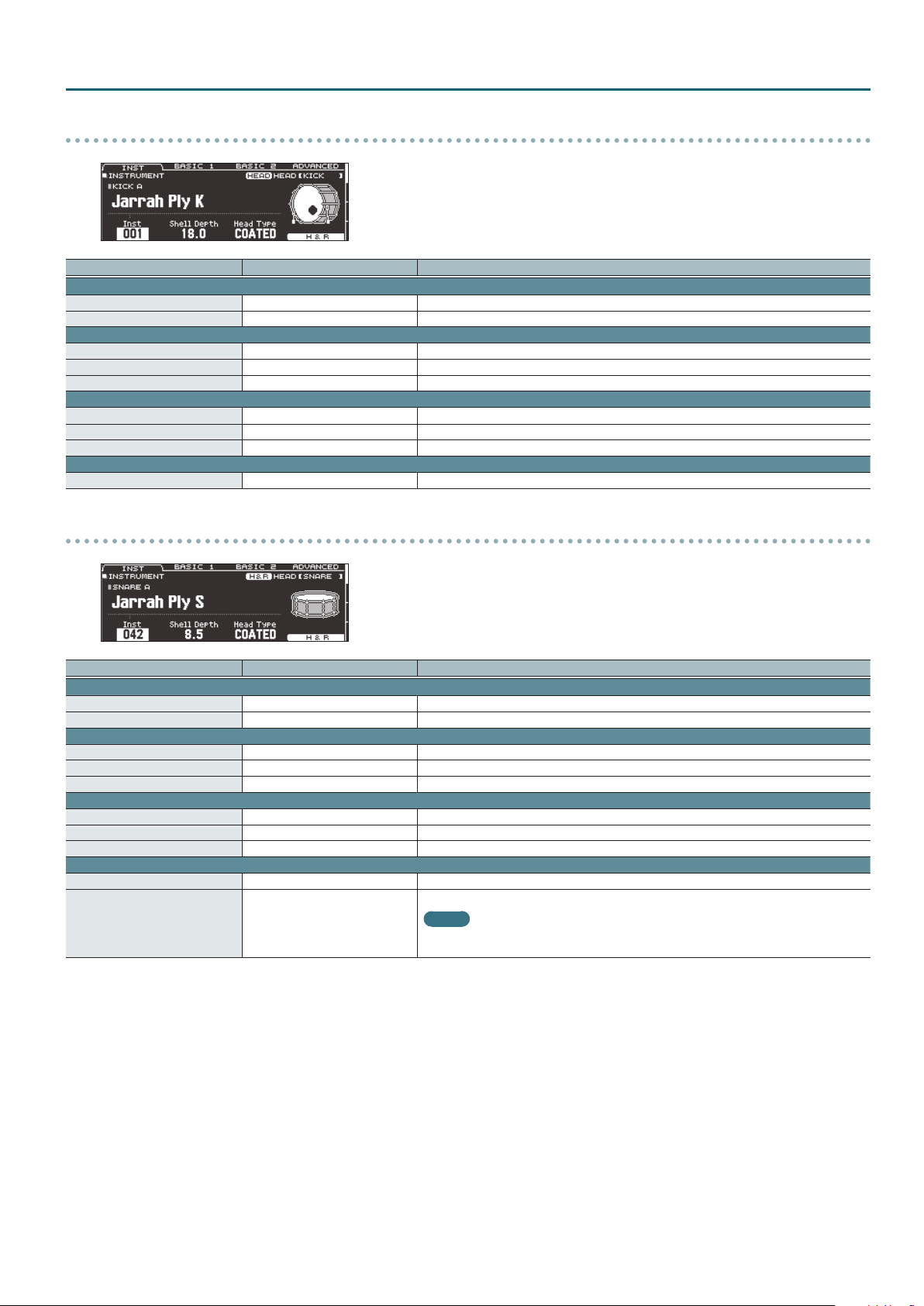
KICK A
Parameter Value Explanation
INST tab
Shell Depth 1.0–30.0 Depth of the shell
Head Type CLEAR, COATED, PINSTRIPE Type of head
BASIC 1 tab
Tuning -100–100 Tuning of the head
Muing
Beater Type FELT1, 2, WOOD, PLASTIC1, 2 Type of beater
BASIC 2 tab
Snare Buzz OFF, 1–8 Resonance to the snare
Low Level -5–NORMAL–+5 Volume of low-frequency sound
Low Decay -2–NORMAL–+2 Decay length of low-frequency sound
ADVANCED tab
Kit Resonance OFF, 1–8 Amount of resonance for the entire drum kit
OFF, TAPE1–4, BLANKET1–3, WEIGHT1, 2
Muing (muting) setting
SNARE A/CROSS STICK/SNARE BRUSH
KIT CUSTOMIZE
Parameter Value Explanation
INST tab
Shell Depth*1 1.0–30.0 Depth of the shell
Head Type*1 CLEAR, COATED, PINSTRIPE Type of head
BASIC 1 tab
Tuning -100–100 Tuning of the head
Muing OFF, TAPE1–7, DONUT1, 2 Muing (muting) setting
Overtone*1, *2 -5–NORMAL–+5 Amount of overtone components
BASIC 2 tab
Strainer Adj.*2 LOOSE1–3, MEDIUM1–3, TIGHT1–3 Tension of the strainer (resonating cords)
Wire Type*2 TYPE1–3 Type of strainer
Wire Level*2 -4–NORMAL–+5 Volume of strainer
ADVANCED tab
XStick Inst*3 1–5 Cross-stick sound selection
Cross-stick sound volume
XStick Inst Volume*3 -INF–+6.0 dB
*1 Unavailable if the instrument group is CROSS STICK.
*2 Unavailable if the instrument group is SNARE BRUSH.
*3 Only if the SNARE A/CROSS STICK instrument is assigned to the rim of the snare (or to the rim of a digitally connected pad that is assigned to snare)
* PINSTRIPE is a registered trademark of Remo Inc., U.S.A.
MEMO
The “XStick Volume” can also be edited from the MIXER DRUM KIT VOLUME screen (KIT VOL tab)
of the MIXER (p. 13).
7
Page 8
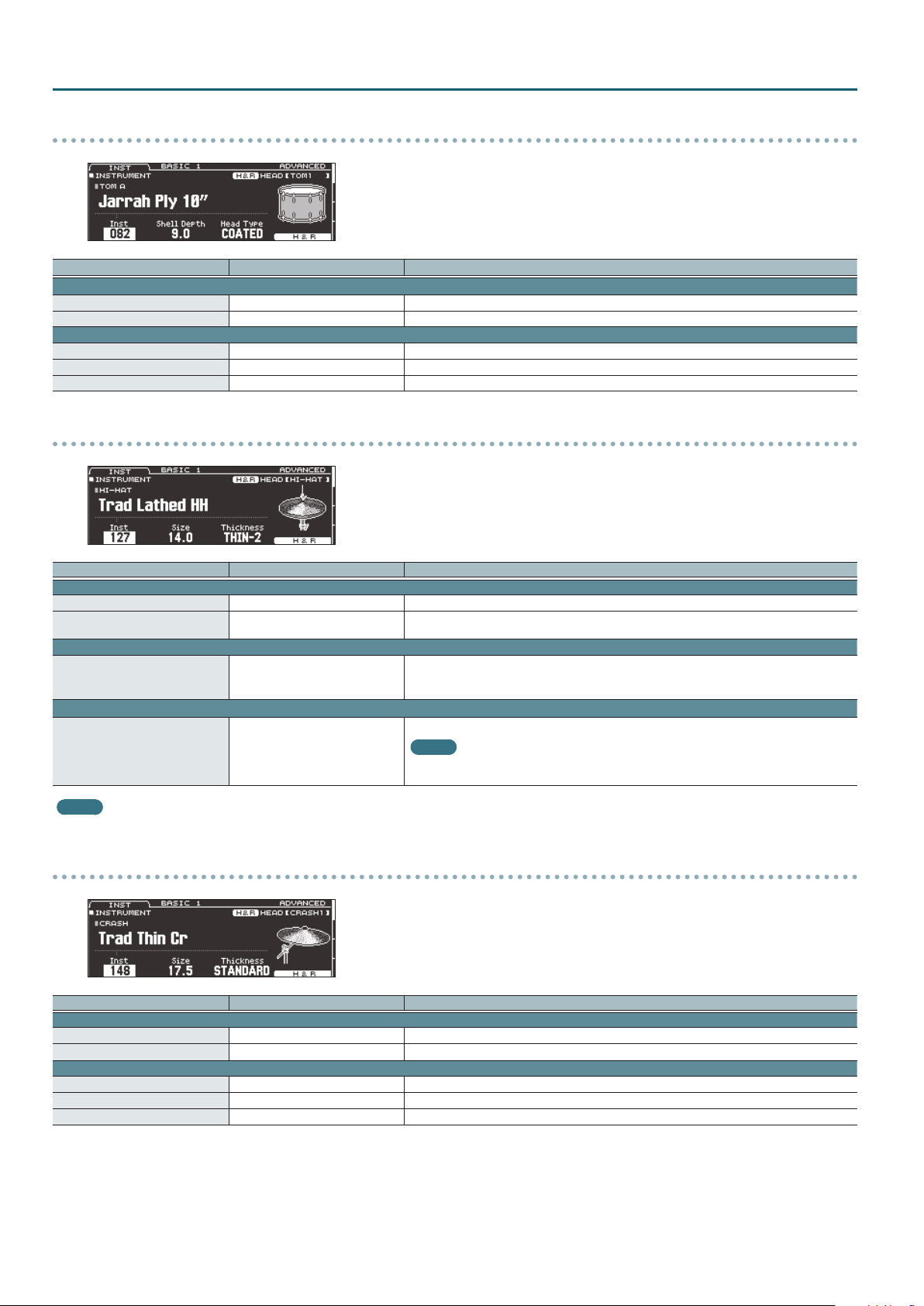
KIT CUSTOMIZE
TOM A/TOM BRUSH
Parameter Value Explanation
INST tab
Shell Depth 1.0–30.0 Depth of the shell
Head Type CLEAR, COATED, PINSTRIPE Type of head
BASIC 1 tab
Tuning -100–100 Tuning of the head
Muing OFF, TAPE1–5, FELT1–4 Muing (muting) setting
Snare Buzz OFF, 1–8 Resonance to the snare
HI-HAT
Parameter Value Explanation
INST tab
Size 1.0–40.0 Hi-hat diameter
Thickness THIN-5–STANDARD–THICK +5 Thickness of the hi-hat
BASIC 1 tab
Fixed NORMAL, PRESS, CLOSE, HALF, OPEN
ADVANCED tab
Pedal HH Volume -INF–+6.0 dB
Openness of the hi-hat
If something other than “NORMAL” is selected, the openness of the hi-hat does not change,
regardless of how you press the hi-hat pedal.
Volume of pedal hi-hat
MEMO
The “Pedal HH Volume” can also be edited from the MIXER DRUM KIT VOLUME screen
(KIT VOL tab) of the MIXER (p. 13).
MEMO
The closed hi-hat position (Fixed = CLOSE) can be enabled by pressing an optional footswitch or hitting a pad switch. Please refer to “CONTROL” (p. 31).
CRASH/CHINA/SPLASH/STACKED CYMBAL
Parameter Value Explanation
INST tab
Size 1.0–40.0 Cymbal diameter
Thickness THIN-5–STANDARD–THICK +5 Thickness of the cymbal
BASIC 1 tab
Muing OFF, TAPE1–19 Muing (muting) setting
Sizzle Type OFF, RIVET, CHAIN, BEADS Type of sizzle
Sizzle Amount -3–+3 Amount of sizzle
8
Page 9
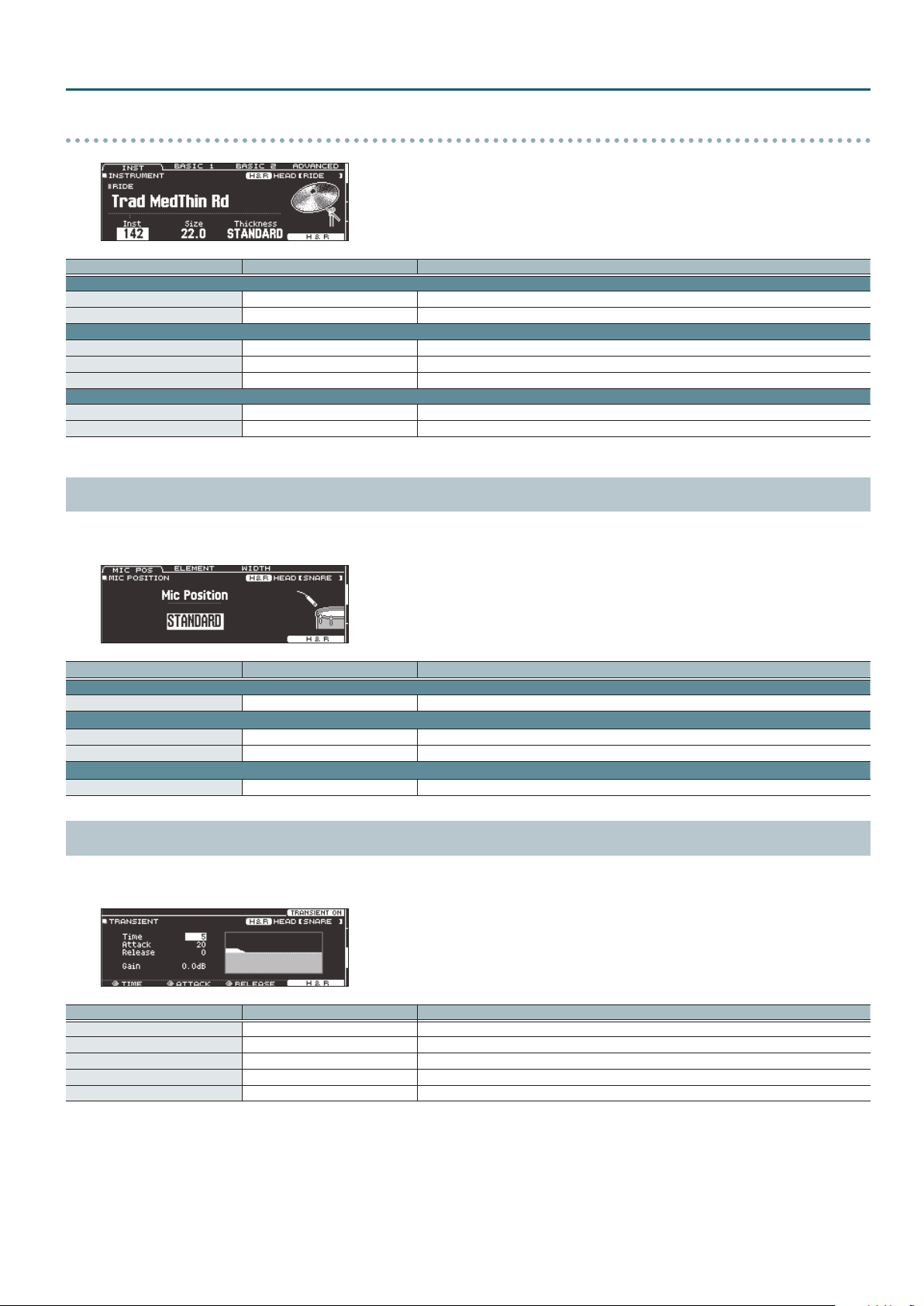
RIDE
Parameter Value Explanation
INST tab
Size 1.0–40.0 Cymbal diameter
Thickness THIN-5–STANDARD–THICK +5 Thickness of the cymbal
BASIC 1 tab
Muing OFF, TAPE1–19 Muing (muting) setting
Sizzle Type OFF, RIVET, CHAIN, BEADS Type of sizzle
Sizzle Amount -3–+3 Amount of sizzle
BASIC 2 tab
Ping Color*1 LIGHT2, 1, STANDARD, HEAVY1, 2 Tonal character of the ride’s ping sound
Ping Level*1 -4–NORMAL–+5 Volume of the ride’s ping sound
*1 For some instruments, these settings are not available.
MIC POSITION (page 2)
You can edit the mic position and volume for each instrument.
* For some instruments, these settings are not available.
KIT CUSTOMIZE
Parameter Value Explanation
MIC POS tab
Mic Position OUTSIDE4–STANDARD–INSIDE4 Tonal change caused by mic position
ELEMENT tab
Overhead -INF–+6.0 dB Volume of overhead mic
Room -INF–+6.0 dB Volume of room mic
WIDTH tab
Mic Width -5–+5 Spread of the overhead mic and room mic
TRANSIENT (page 3)
You can adjust the attack and release (transient) for each instrument.
* For some instruments, these settings are not available.
Parameter Value Explanation
[F4] button OFF, TRANSIENT ON Turns the transient eect on/o.
Time ([R1] knob) 1–10 Time over which the attack changes
Attack ([R2] knob) -100–+100 Adjustment of the attack
Release ([R3] knob) -100–+100 Adjustment of the release
Gain -12.0–+6.0 dB Volume following transient adjustment
9
Page 10
KIT CUSTOMIZE
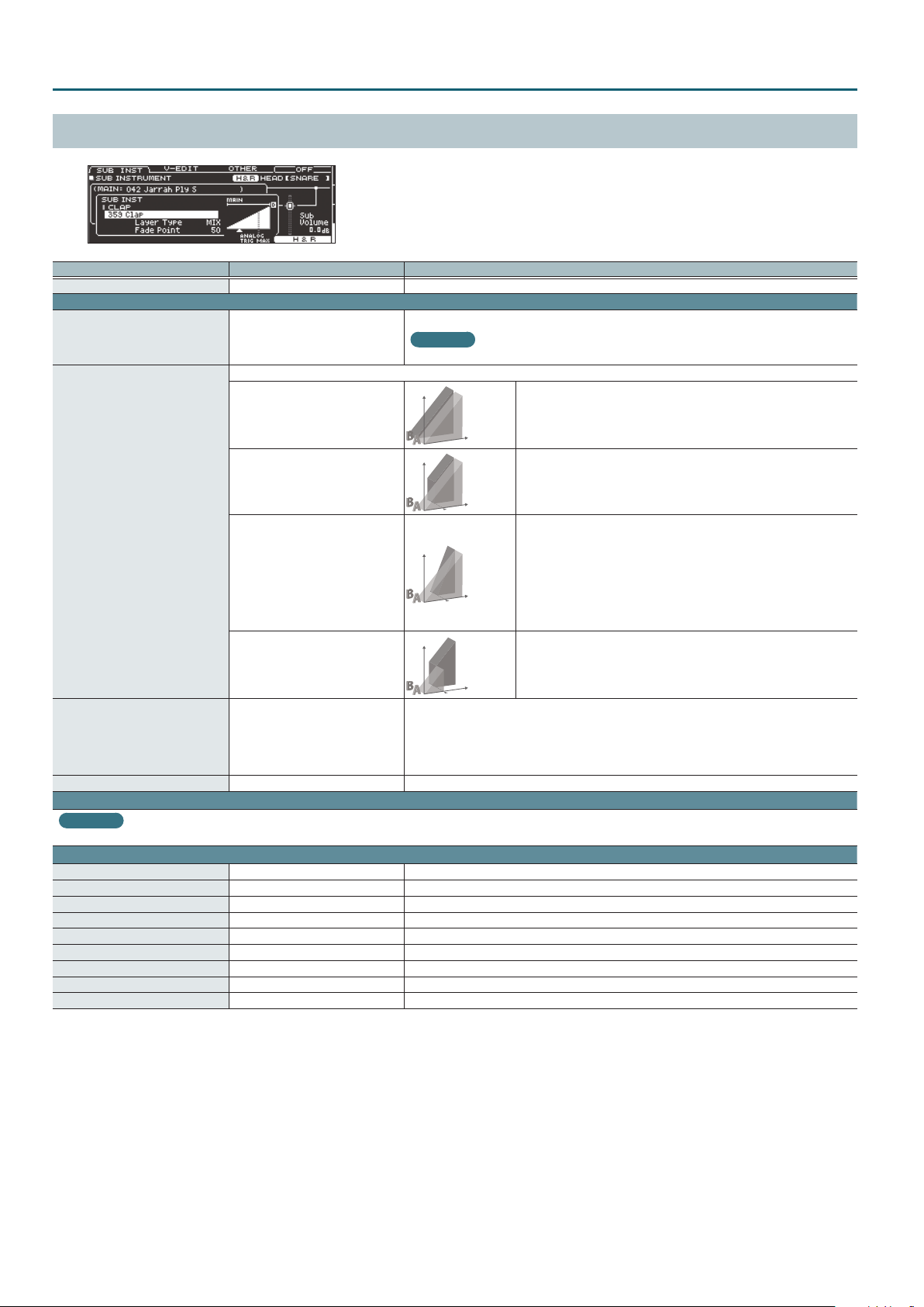
SUB INST (page 4)
Parameter Value Explanation
[F4] button OFF, SUB ON Turns the sub-instrument on/o.
SUB INST tab
SUB INST
Layer Type
Fade Point 1–127+32
Sub Volume -INF–+6.0 dB Volume of the sub-instrument
V-EDIT tab
001– (preset)
U001–U500 (user sample)
These parameters specify how the sub instrument will be sounded.
MIX
FADE1
FADE2, FADE3
SWITCH
Reference
For details on the parameters that can be edited, refer to “INSTRUMENT (page 1)” (p. 6).
OTHER tab
Mic Position OUTSIDE4–STANDARD–INSIDE4 Tonal change caused by mic position
Mic Overhead -INF–+6.0 dB Volume of the overhead mics
Mic Room -INF–+6.0 dB Volume of the room mics
Mic Width -5–+5 Spread of the overhead mics and the room mics
Transient Sw OFF, TRANSIENT ON Transient on/o
Transient Time 1–10 Time over which the attack changes
Transient Attack -100–+100 Adjustment of the attack
Transient Release -100–+100 Adjustment of the release
Transient Gain -12.0–+6.0 dB Volume following transient adjustment
Sub-instrument number
Reference
For more about instruments, refer to “Instrument List” (p. 42).
Volume
The main instrument (A) and sub instrument (B) always sound together as
Playing
Volume
Volume
Volume
Species the force of the strike at which the sub instrument begins to be sounded.
If this is “1,” the sub instrument is sounded by a strike of any force.
If this is “127” (“127+32” for a pad that supports digital connection), the sub instrument is sounded
only by the strongest strike.
* This is not available if Layer Type is “MIX.”
Dynamics
Playing
Dynamics
Playing
Dynamics
Playing
Dynamics
a layer.
The sub instrument (B) is added as a layer only if the strike is stronger than
“Fade Point.”
If the strike is stronger than “Fade Point,” the sub instrument (B) is added as
a layer according to the strength of that strike.
FADE2:
At 127 or higher, the main instrument (A) and sub instrument (B) are the
same volume.
FADE3:
At 127+32, the main instrument (A) and sub instrument (B) are the same
volume (for pads that support digital connection).
Strikes weaker than “Fade Point” sound the main instrument (A), and strikes
stronger than “Fade Point” switch to sound the sub instrument (B).
* For some instruments, these settings are not available.
10
Page 11
AMBIENCE
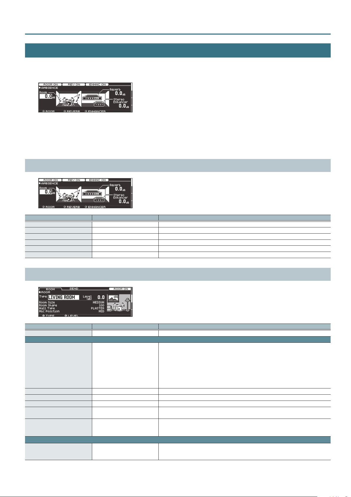
1. Press the [AMBIENCE] button.
The AMBIENCE screen appears.
2. Use the PAGE [UP] [DOWN] buttons to access the editing screen.
3. Use cursor buttons to select a parameter, and use the [–] [+] buttons or the dial to edit the value.
4. Press the [KIT] button to return to the DRUM KIT screen.
AMBIENCE LEVEL (page 1)
KIT CUSTOMIZE
Parameter Value Explanation
[F1] button ROOM OFF, ROOM ON Turns the room ambience (the type and size of room) eect on/o.
[F2] button REV OFF, REV ON Turns the reverb (reverberation) eect on/o.
[F3] button ENHNC OFF, ENHNC ON Turns the stereo enhancer (spaciousness) eect on/o.
Room ([R1] knob) -INF–+6.0 dB Volume of room ambience
Reverb ([R2] knob) -INF–+6.0 dB Volume of reverb
Stereo Enhancer ([R3] knob) -INF–+6.0 dB Volume of stereo enhancer
ROOM (page 2)
Parameter Value Explanation
[F4] button OFF, ROOM ON Turns room ambience on/o.
ROOM tab
BEACH, LIVING ROOM, BATH ROOM,
STUDIO, GARAGE, LOCKER ROOM,
THEATER, CAVE, GYMNASIUM,
Type ([R1] knob)
Level ([R2] knob) -INF–+6.0 dB Volume of room ambience
Room Size TINY, SMALL, MEDIUM, LARGE, HUGE Size of the room
Room Shape 0–100 Room shape and reverberation length
Wall Type
Mic Position
SEND tab
Room Send Volume -INF–+6.0 dB
DOME STADIUM, BOOTH A, BOOTH
B, STUDIO A, STUDIO B, BASEMENT,
JAZZ CLUB, ROCK CLUB, BALLROOM,
GATE, CONCERT HALL, SPORTS
ARENA, EXPO HALL, BOTTLE, CITY,
SPIRAL
CURTAIN, CLOTH, WOOD,
PLASTER, CONCRETE, GLASS
NEXT DOOR, LOW FLOOR,
LOW, MID LOW, MID,
MID HIGH, HIGH, CEILING A, CEILING B
Type of room reverberation
Wall material
Tonal change caused by mic position
Amount of room ambience applied to each pad
If you press the [F5] (H&R) button to turn it “ON,” you can simultaneously make settings for the head
area and rim area, etc.
11
Page 12
KIT CUSTOMIZE
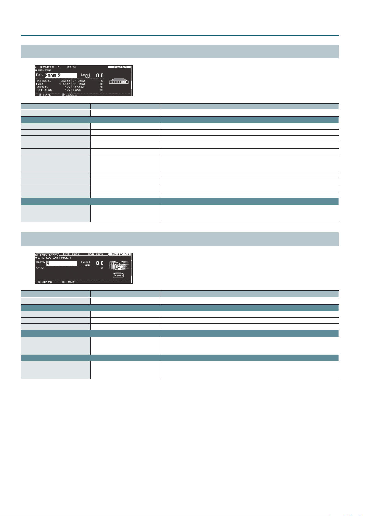
REVERB (page 3)
Parameter Value Explanation
[F4] button OFF, REV ON Turns reverb on/o.
ROOM tab
Type ([R1] knob) ROOM 1, 2, HALL 1, 2, PLATE Type of reverb
Level ([R2] knob) -INF–+6.0 dB Volume of reverb
Pre Delay 0–100 mSec Adjusts the delay time from the direct sound until the reverb sound is heard
Time 0.1–10.0 Sec Time length of reverberation
Density 0–127 Density of reverb sound
Diusion 0–127
LF Damp 0–100 Adjusts the low-frequency region of the reverb sound.
HF Damp 0–100 Adjusts the high-frequency region of the reverb sound.
Spread 0–127 Spread of the reverb sound
Tone 0–127 Tonal character of reverb sound
SEND tab
Reverb Send Volume -INF–+6.0 dB
Change in the density of the reverb sound over time
The higher the value, the denser the sound becomes as time elapses (The eect is more obvious for
longer reverb times).
Amount of reverb applied to each pad
If you press the [F5] (H&R) button to turn it “ON,” you can simultaneously make settings for the head
area and rim area, etc.
STEREO ENHANCER (page 4)
Parameter Value Explanation
[F4] button OFF, ENHNC ON Turns stereo enhancer on/o.
ROOM tab
Width ([R1] knob) MONO, 1–4 Spread of stereo enhancer
Level ([R2] knob) -INF–+6.0 dB Volume of stereo enhancer
Color 1–6 Tonal character of stereo enhancer
MAIN SEND tab
Stereo Enhancer Main Inst Send
SUB SEND tab
Stereo Enhancer Sub Inst Send -INF–+6.0 dB
-INF–+6.0 dB
Amount of stereo enhancer applied to each pad (main instrument)
If you press the [F5] (H&R) button to turn it “ON,” you can simultaneously make settings for the head
area and rim area, etc.
Amount of stereo enhancer applied to each pad (sub-instrument)
If you press the [F5] (H&R) button to turn it “ON,” you can simultaneously make settings for the head
area and rim area, etc.
12
Page 13
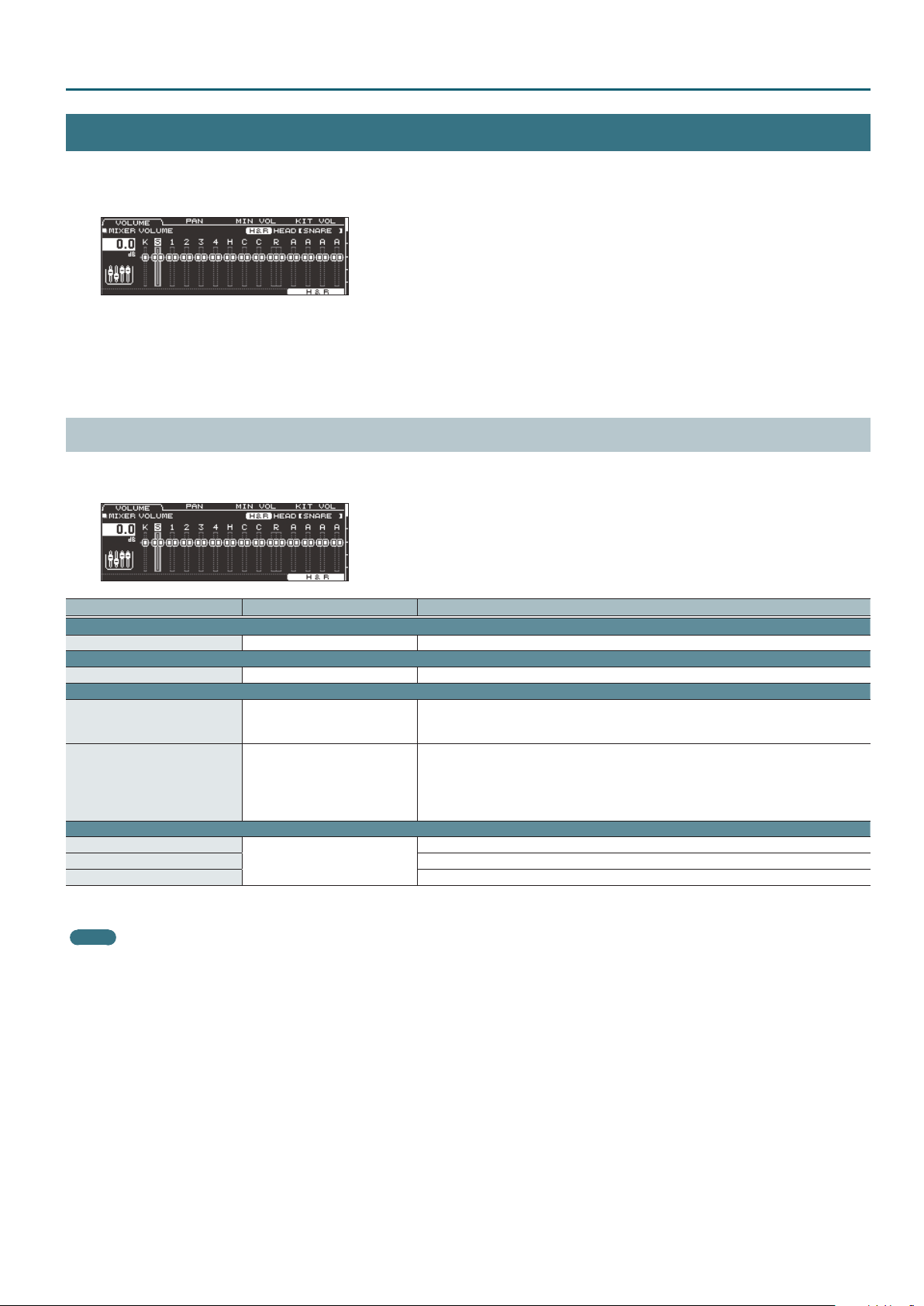
MIXER
1. Press the [MIXER] button.
The MIXER screen appears.
2. Use the PAGE [UP] [DOWN] buttons to access the editing screen.
3. Use cursor buttons to select a parameter, and use the [–] [+] buttons or the dial to edit the value.
4. Press the [KIT] button to return to the DRUM KIT screen.
MIXER VOLUME (page 1)
For each drum kit, you can adjust the volume of each pad and adjust the overall volume of the entire drum kit.
You can also adjust how the volume responds to the striking force.
KIT CUSTOMIZE
Parameter Value Explanation
VOLUME tab
Volume -INF–+6.0 dB Volume of each pad
PAN tab
Pan L30–CTR–R30 Stereo position of each pad
MIN VOL tab
Pad Minimum Volume*1 0–15
Pad Maximum Volume*1 -5–0
KIT VOL tab
Kit Volume*2
Pedal HH Volume Pedal hi-hat volume
Xstick Volume Cross-stick volume
*1 Use the cursor [H] [I] buttons to choose whether you’re setting the Pad Minimum Volume or the Pad Maximum Volume.
*2 You can also set “Kit Volume” in the KIT SETTINGS screen (VOLUME tab) (p. 3).
MEMO
If you press the [F5] (H&R) button to turn it “ON,” you can simultaneously make settings for the head area and rim area, etc.
-INF–+6.0 dB
Minimum volume of each pad
This lets you increase the volume of the softest hits while preserving the volume of the strongest
hits. This can make it easier to hear ghost notes on the snare or legato notes on the ride cymbal.
Maximum volume of each pad
This lets you decrease the volume of the strongest hits while preserving their nuances.
You can limit the volume while preserving the nuances of the strongest hits.
* This is available only for pads that support digital connection and for input from the MIDI IN
connector.
Drum kit volume
13
Page 14
KIT CUSTOMIZE
PAD EQ (page 2)
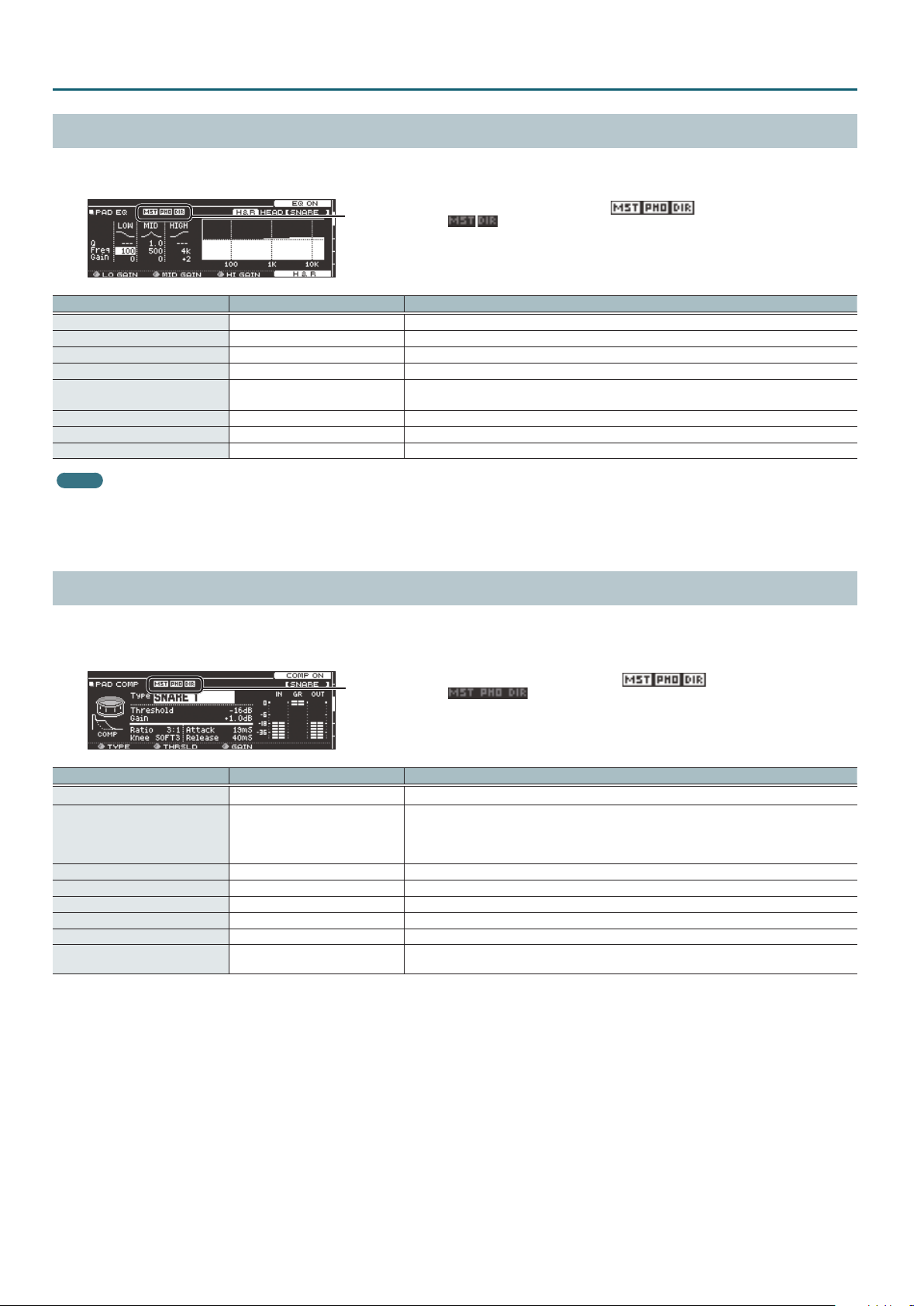
This is a three-band equalizer that each drum kit provides for each strike location of each pad.
You can disable the pad equalizer eect that is output from the DIRECT OUT jacks (p. 29).
This indicates whether the pad equalizer eect is output ( ) from each
jack or is not output ( ).
MST: MASTER OUT jacks
PHO: PHONES jacks (always output)
DIR: DIRECT OUT jacks
Parameter Value Explanation
[F4] button OFF, EQ ON Turns pad equalizer on/o.
Low Freq 20 Hz–1 kHz Center frequency of the low range
Low Gain ([R1] knob) -15–+15 dB Amount of boost/cut for the low range
Mid Freq 20 Hz–16 kHz Center frequency of the mid range
Mid Q 0.5–8.0
Mid Gain ([R2] knob) -15–+15 dB Amount of boost/cut for the mid range
High Freq 1 kHz–16 kHz Center frequency of the high range
High Gain ([R3] knob) -15–+15 dB Amount of boost/cut for the high range
MEMO
If you press the [F5] (H&R) button to turn it “ON,” you can simultaneously make settings for the head area and rim area, etc.
* If the routing setting (p. 29) PadEq/Comp to direct is “OFF,” the pad equalizer eect does not apply to the sound that is output from the DIRECT OUT jacks.
* If the routing setting (p. 29) PadEq/Comp to direct is “OFF,” and Master OUT is set to “DIRECT,” the pad equalizer eect does not apply to the sound that is output from the DIRECT
OUT jacks and MASTER OUT jacks.
Width of the frequency range
A higher Mid Q narrows the aected area.
PAD COMP (page 3)
This is a compressor that each drum kit provides for each pad.
The pad compressor eect can be applied only to the output from the DIRECT OUT jacks. You can also disable the pad compressor eect from being
applied to the PHONES jack output (p. 29).
This indicates whether the pad compressor eect is output ( ) from each
jack or is not output ( ).
MST: MASTER OUT jacks
PHO: PHONES jacks
DIR: DIRECT OUT jacks
Parameter Value Explanation
[F4] button OFF, COMP ON Turns pad compressor on/o.
Type ([R1] knob)
Threshold ([R2] knob) -48–0 dB Volume level at which compression begins
Gain ([R3] knob) -24–+24 dB Output level of the compressor
Ratio 1:1–100:1 Compression ratio
Knee HARD, SOFT1–3 Attack of the sound at the moment compression is applied
Attack 0–100 mSec Time from when the volume goes up the threshold level until the compressor eect applies
Release 10–1000 mSec
* Pad compressor settings are made for individual pads. They cannot be made for individual strike locations (such as the head or rim).
* If the routing setting (p. 29) PadEq/Comp to direct is “OFF,” the pad compressor eect does not apply to the sound that is output from the DIRECT OUT jacks.
* If the routing setting (p. 29) PadEq/Comp to direct is “OFF,” and Master Out is set to “DIRECT,” the pad compressor eect does not apply to the sound that is output from the
DIRECT OUT jacks and the MASTER OUT jacks.
* If the routing setting (p. 29) PadComp to Phones is “OFF,” the pad compressor eect does not apply to the sound that is output from the PHONES jacks.
KICK 1, 2, SNARE1, 2, TOM 1, 2, CYM 1,
2, SOFT, HARD, LIMITER
Character of the compressor
* When you change this parameter, the pad compressor’s parameters Ratio, Knee, Attack, and
Release change to optimal settings for your selection. You can then make further adjustments to
these parameters as necessary.
Time from when the volume falls below the threshold level until the compressor eect no longer
applies
14
Page 15
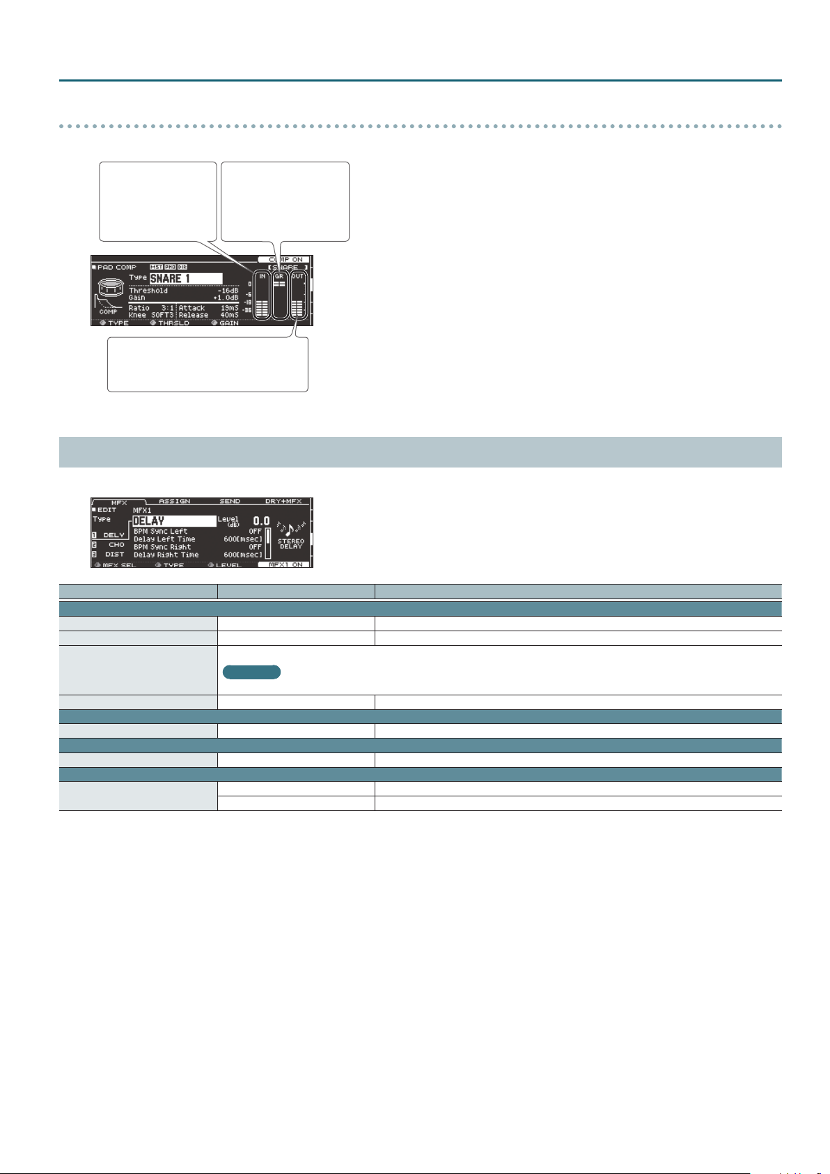
Meters shown in the PAD COMP screen
In the PAD COMP screen, the “input meter,” the “gain reduction meter,” and the “output meter” are displayed.
KIT CUSTOMIZE
Input meter
The “input meter”
shows the level (dB)
being input to the pad
compressor.
Output meter
The “output meter” shows the output level
following the pad compressor.
Gain reduction meter
The “gain reduction meter”
shows the change in level
(dB) produced by the pad
compressor.
Adjust the pad compressor’s “Gain” so that the output meter does not exceed 0 dB (i.e., so that it does not clip).
MULTI EFFECT (MFX) (page 4)
You can use three multi-eects simultaneously for each drum kit.
Parameter Value Explanation
MFX tab
[F5] button OFF, MFX1–3 ON Turns on/o the multi-eect 1–3 selected by the [R1] knob.
MFX SEL ([R1] knob) MFX1–3 You can use three multi-eects simultaneously for each drum kit.
Type of multi-eect
Type ([R2] knob)
Level ([R3] knob) -INF–+6.0 dB Volume of the eect sound for the selected multi-eect
ASSIGN tab
MFX Assign MFX1–3 Select the multi-eect 1–3 that is applied to each pad.
SEND tab
MFX Send Volume -INF–+6.0 dB Eect send level for each pad
DRY+MFX tab
MFX DRY+WET*1
*1 MFX DRY+WET is specied for each pad. It cannot be specied for individual strike locations (such as the head or rim).
If MFX DRY+WET is set to “MFX ONLY,” some multi-eect settings might cause no sound to be output.
Reference
For more about multi-eects, refer to “Multi-Eect Parameters” (p. 34).
DRY+MFX The dry sound and eect sound will be output.
MFX ONLY Only the eect sound will be output.
15
Page 16
KIT CUSTOMIZE
MASTER COMP (page 5)
This is a two-band equalizer that is provided for each drum kit.
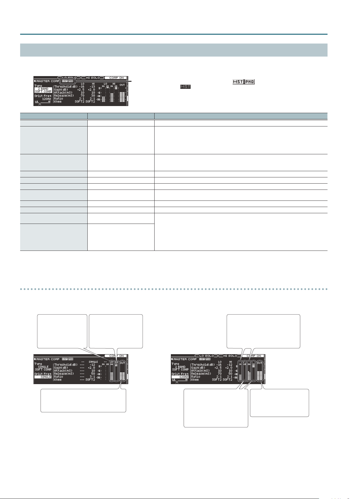
The master compressor is output from the MASTER OUT jacks and the PHONES jacks.
This indicates whether the master comp eect is output ( ) from
each jack or is not output ( ).
MST: MASTER OUT jacks
PHO: PHONES jacks (always output)
Parameter Value Explanation
[F4] button OFF, COMP ON Turns master comp on/o.
SINGLE SOFT COMP, SINGLE HARD
Type
Split Freq SINGLE, 10–16000 Hz
Threshold*1 -48–0 dB Volume level at which compression begins
Gain*1 -24–+24 dB Output level of the compressor
Attack*1 0–100 mSec Time from when the volume goes up the threshold level until the compressor eect applies
Release*1 10–1000 mSec
Ratio*1 1:1–100:1 Compression ratio
Knee*1 HARD, SOFT1–3 Attack of the sound at the moment compression is applied
[F2] button*2 LO SOLO
[F3] button*2 HI SOLO
*1 If Split Freq is set to something other than “SINGLE,” the low band and high band can be set independently.
*2 Only if Split Freq is set to something other than “SINGLE”
* If the routing setting (p. 29) Master Out is “DIRECT,” the master compressor does not apply to the sound that is output from the MASTER OUT jacks.
COMP, SINGLE LIMITER, 2BAND SOFT
COMP, 2BAND HARD COMP, 2BAND
LIMITER
Character of the compressor
* When you change this parameter, all parameters of the master compressor change to optimal
settings for your selection. You can then make further adjustments to these parameters as
necessary. Depending on the settings of these parameters, the resulting eect might not match
the Type setting.
Bandwidth of the compressor
If this is “SINGLE,” the master compressor operates as a single-band compressor that is used only on
the high band.
Time from when the volume falls below the threshold level until the compressor eect no longer
applies
When this is operating as a two-band compressor, you can individually audition the low-frequency
and high-frequency bands.
* These settings are reset if you perform any of the following operations.
5 Respecify the Type parameter as single band compressor
5 Set the Split Freq parameter to “SINGLE”
5 Exit the MASTER COMP screen
Meters shown in the MASTER COMP screen
In the MASTER COMP screen, the “input meter,” the “gain reduction meter,” and the “output meter” are displayed.
When Split Freq is “SINGLE” (single compressor) When Split Freq is “10–16000 Hz” (2-band compressor)
Input meter
The “input meter” shows
the level (dB) being
input to the master
comp.
Output meter
The “output meter” shows the output level
following the master comp.
Adjust the master comp’s “Gain” so that the output meter does not exceed 0 dB (i.e., so that it does not clip).
Gain reduction meter
The “gain reduction meter”
shows the change in level
(dB) produced by the
master comp.
Input meter
The “input meter” shows the level (dB)
being input to the master comp.
This is shown individually for the low
and high bands.
Gain reduction meter
The “gain reduction meter”
shows the change in level (dB)
produced by the master comp.
This is shown individually for the
low and high bands.
Output meter
The “output meter” shows the
output level following the
master comp.
16
Page 17
MASTER EQ (page 6)
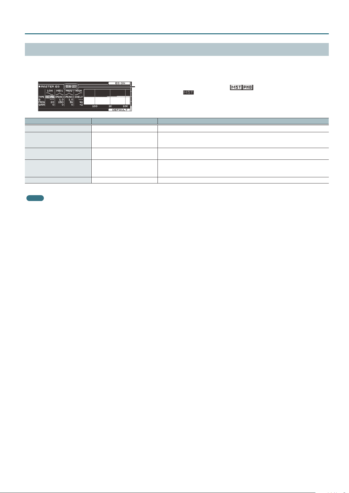
This is a four-band equalizer that is provided for each drum kit.
You can adjust the equalizer’s eect (shelving and peaking) for the low frequency (LOW) and high frequency (HIGH).
The master EQ is not output from the MASTER OUT jacks and PHONES jacks.
This indicates whether the master EQ eect is output ( ) from
each jack or is not output ( ).
MST: MASTER OUT jacks
PHO: PHONES jacks (always output)
Parameter Value Explanation
[F4] button OFF, EQ ON Turns master EQ on/o.
Type
Q
Freq
Gain -12–+12 dB Amount of boost/cut
* If the routing setting (p. 29) Master Out is set to “DIRECT,” the eect of the master EQ does not apply to the sound that is output from the MASTER OUT jacks.
MEMO
To return to the default values, press the [F5] (DEFAULT) button.
SHELV (Shelving),
PEAK (MID1 and MID2: xed to
“PEAK”)
0.5–8.0 (only when Type is set to
“PEAK”)
20 Hz– 1 kHz (LOW)
20 Hz–16 kHz (MID1, 2)
1 kHz–16 kHz (HIGH)
Type of equalizer
Width of the frequency range
A higher Q narrows the aected area.
Center frequency
KIT CUSTOMIZE
17
Page 18
USER SAMPLE
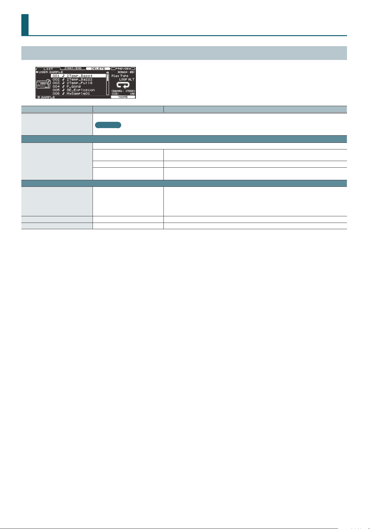
SAMPLE LIST
Parameter Value Explanation
Renames the currently selected user sample.
[F5] button
LIST tab
Play Type
START/END tab
Zoom ([R1] knob) –
Start ([R2] knob)*1 0–07937742 Adjusts the start point (the location at which the user sample starts playing).
End ([R3] knob)*1 257–07937999 Adjusts the end point (the location at which the user sample stops playing).
*1 You can’t set the end point earlier than the start point.
You can’t set the start point and end point to the same value.
For both the start point and end point, you can’t specify a value that exceeds the length of the user sample.
Reference
For details on how to assign a name, refer to “Renaming a Drum Kit” in “Reference Manual” (PDF).
Species how the user sample is sounded.
ONESHOT MONO
ONESHOT POLY When you strike the pad repeatedly, the sounds of the notes are heard overlapping.
LOOP ALT
When you strike the pad, the currently-heard sound is silenced before the new sound is heard.
Notes do not overlap.
The user sample plays repeatedly (loop).
Each time you strike the pad, the sound alternately plays or stops.
Zooms the waveform display in or out.
You can zoom-in/out on the horizontal axis by turning the [R1] knob or by holding down the
[SHIFT] button and pressing the cursor [K] [J] buttons.
If you hold down the [SHIFT] button and turn the [R1] knob or use the cursor [H] [I] buttons, you’ll
zoom-in/out on the vertical axis.
18
Page 19
SONG
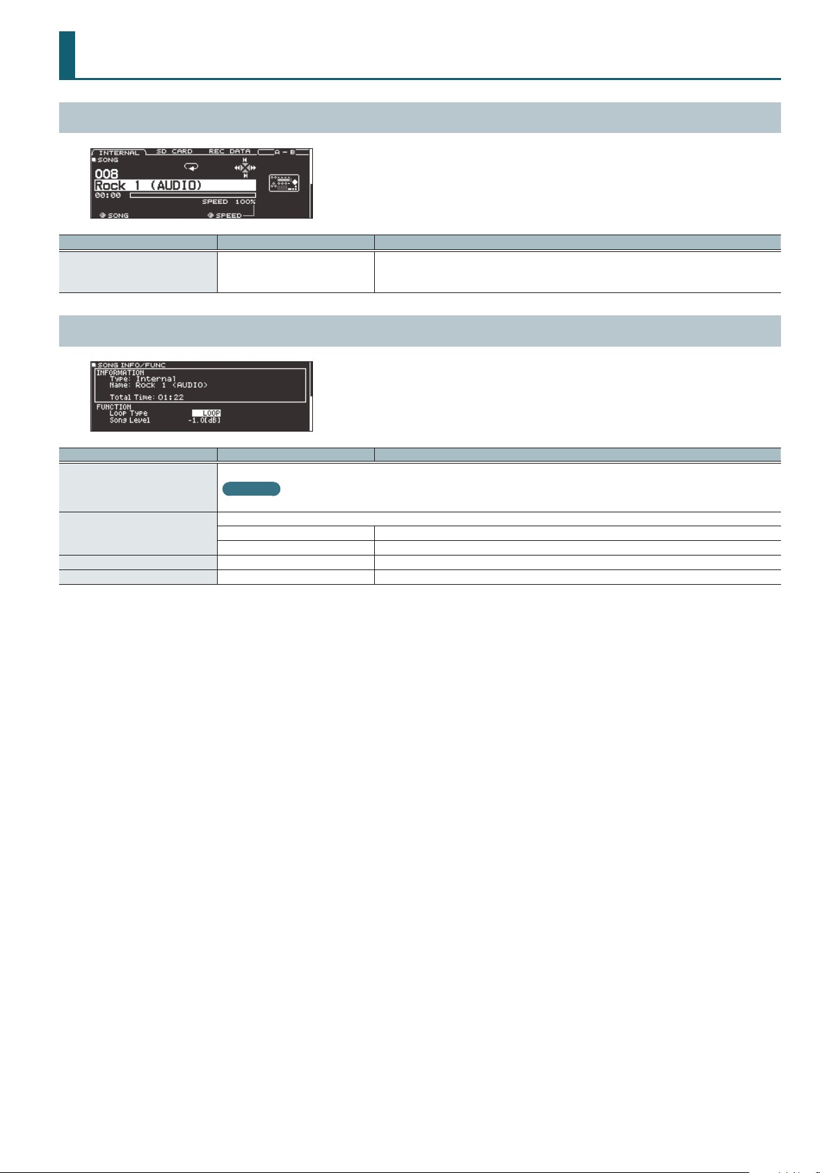
SONG (page 1)
Parameter Value Explanation
Speed ([R3] knob) 50–150 %
SONG INFO (page 2)
Parameter Value Explanation
Change the name of recorded data.
[F4] button*1
Loop Type
Song Level -INF–+6.0 [dB] Song volume
Click Track Level*2 -INF–+6.0 [dB] Click track volume
*1 Only recorded data
*2 Only if there is a click track corresponding to the song
Reference
For details on how to assign a name, refer to “Renaming a Drum Kit” in “Reference Manual” (PDF).
Species how the song is played back.
ONE SHOT Play back only once and then stop.
LOOP Play repeatedly.
Changes the song’s (audio le) playback speed.
* When you switch songs, this returns to 100%. Depending on the type of song, this might not be
available.
19
Page 20
SET LIST
SETUP
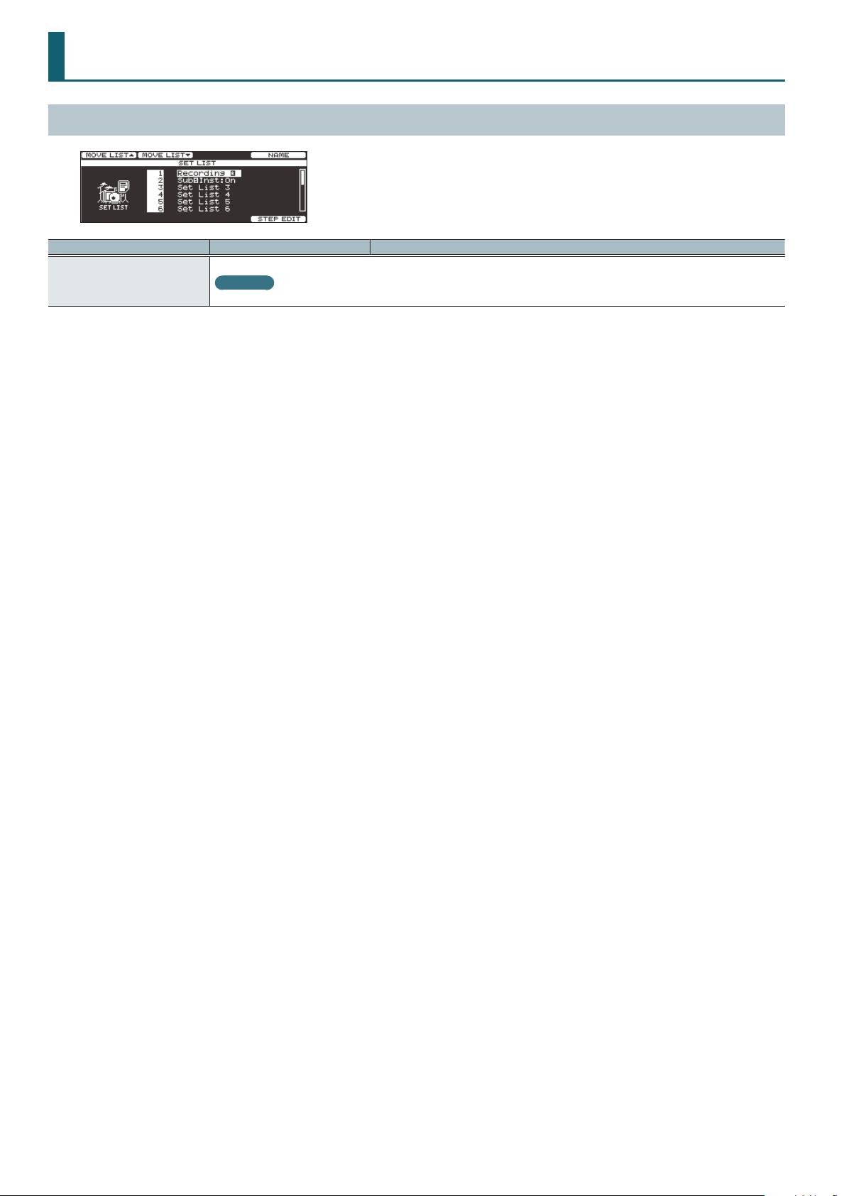
Parameter Value Explanation
Renames the set list.
[F4] button
Reference
For details on how to assign a name, refer to “Renaming a Drum Kit” in “Reference Manual” (PDF).
20
Page 21
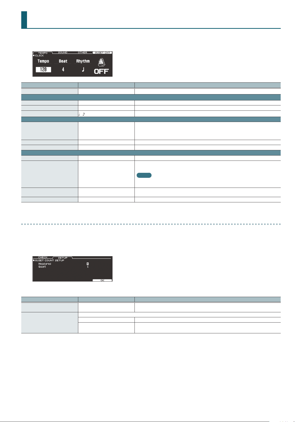
CLICK
1. Press the [CLICK] button.
The CLICK screen appears.
Parameter Value Explanation
[F5] button OFF, ON Turns click on/o.
TEMPO tab
Tempo*1 20–260 Tempo
Beat*1 1–9 Number of beats per measure
Rhythm
SOUND tab
Sound
Level -INF–+6.0 dB Volume of click
LED Ref OFF, ON Species whether the [CLICK] button blinks in time with the click (ON) or does not blink (OFF).
OTHER tab
Click Pan L30–CTR (CENTER)–R30 Stereo position of the click
Amb(Reverb)Send -INF–+6.0 dB
Tap Sw OFF, ON
Tap Pad KICK–PREVIEW Select the pad or button that can be struck or pressed to set the tap tempo.
*1 This cannot be changed while playing back a drum performance data song (p. 46) or recorded data.
–
METRONOME, CLICK, VOICE, BEEP 1,
BEEP 2, TEK CLICK, STICKS, CLAVES,
WOOD BLOCK, COWBELL, TRIANGLE,
TAMBOURINE, MARACAS, CABASA
Interval of the click
Sound for the click
Depth of ambience reverb
Applying ambience reverb makes the click easier to hear.
MEMO
The eect specied by the ambience reverb setting is applied. This means that reverb must be
turned on (p. 12).
You can specify the tempo by striking the pad specied by Tap Pad or by pressing a button
(Tap Tempo).
Quiet Count settings
1. In the CLICK screen, press the [F4] (QUIET CNT) button.
2. Press the [F2] (SETUP) button.
The setting screen appears.
3. Use cursor buttons to select a parameter, and use the [–] [+] buttons or the dial to edit the value.
Parameter Value Explanation
Measures 2, 4, 8, 16 (Measures)
Of the measures specied by “Measures,” this setting species the length of the measures that will be “Quiet.”
Quiet
RANDOM The length of the Quiet interval will randomly change each time.
1, 2, 4
Specify the length (measures) of the interval for which the click will alternate between “Sounding”
and “Quiet.”
Species the length (number of measures) of the Quiet interval.
* This setting cannot be longer than half of the Measures value.
21
Page 22
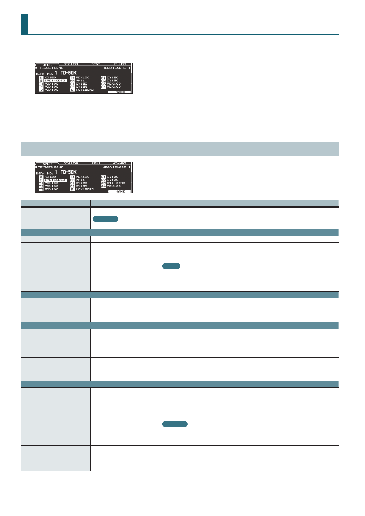
TRIGGER
1. Press the [TRIGGER] button.
The TRIGGER screen appears.
2. Use the PAGE [UP] [DOWN] buttons to access the editing screen.
3. Use cursor buttons to select a parameter, and use the [–] [+] buttons or the dial to edit the value.
4. Press the [KIT] button to return to the DRUM KIT screen.
TRIG BASIC (page 1)
Parameter Value Explanation
Renames the trigger bank.
[F5] button
BANK tab
Bank No. 1–8 Trigger bank number
Trig Type
DIGITAL tab
Assign N/A, KICK–AUX4
SENS tab
Trig Type This parameter is the same as the Trig Type parameter of the BANK tab.
Sensitivity 1.0–32.0
Rim Gain 0–3.2
HI-HAT tab
Trig Type This parameter is the same as the Trig Type parameter of the BANK tab.
Hi-Hat Type
Oset*1, *2 -100–+100 (automatically)
Foot Splash Sens*2 -10–+10 Amount of how easy to make the foot splash
Noise Cancel*1, *2 1–3
CC MAX*2, *3 90, 127
*1 Only if Trig Type is set to “VH13” or “VH12.”
*2 Digitally-connected pads do not support hi-hat pedal performance.
*3 Only if Trig Type is set to something other than “VH13” or “VH12”
22
Reference
For details on how to assign a name, refer to “Renaming a Drum Kit” in “Reference Manual” (PDF).
Species the model of pad (trigger type) that is connected to each trigger input.
* You can’t change the trigger type of a trigger input that’s assigned to a pad that supports a
digital connection.
For details, refer to “Trig Type list”
(p. 23).
Type of hi-hat
This is set automatically according to the parameter selected in Trig Type.
MEMO
When you specify the trigger type, the trigger parameters (with the exception of certain
parameters such as cross-stick cancel) are set to optimal values. These values are only general
guidelines; you can make ne adjustments as appropriate according to how you attach the pad
and how you use it.
Species the trigger input to which a digitally-connected pad is assigned.
A digitally connected pad for which you select “N/A” is not used; the settings of the pad connected
to the TRIGGER IN jack are applied.
* Even if this is assigned to “HI-HAT,” hi-hat open/close techniques cannot be performed.
You can adjust the sensitivity of the pads to accommodate your personal playing style.
Increasing this value increases the sensitivity, so that even soft strikes on the pad are sounded at
high volume. Decreasing this value decreases the sensitivity, so that even strong strikes on the pad
are sounded at low volume.
Adjusts the balance between the force of striking the rim or edge and the loudness of the sound.
If you increase this value, even soft strikes on the rim are sounded at high volume. If you decrease
this value, even strong strikes on the rim are sounded at low volume.
This is available for pads that support rim shots.
Extent of opening Hi-Hat
The bigger the value is, the wider the opening extent is.
Reference
For details on how to adjust the oset, refer to “Reference Manual.” You can make ne
adjustments to the hi-hat parameters as necessary.
Amount of strength to cancel the bow and edge noise when you play foot close.
The bigger the value is, the more dicult to have a noise excluding the foot close.
Amount of control change that is transmitted in stepping the hi-hat pedal down completely.
* There’s no need to change this setting if you’re performed only with the TD-50 and the pads.
Page 23
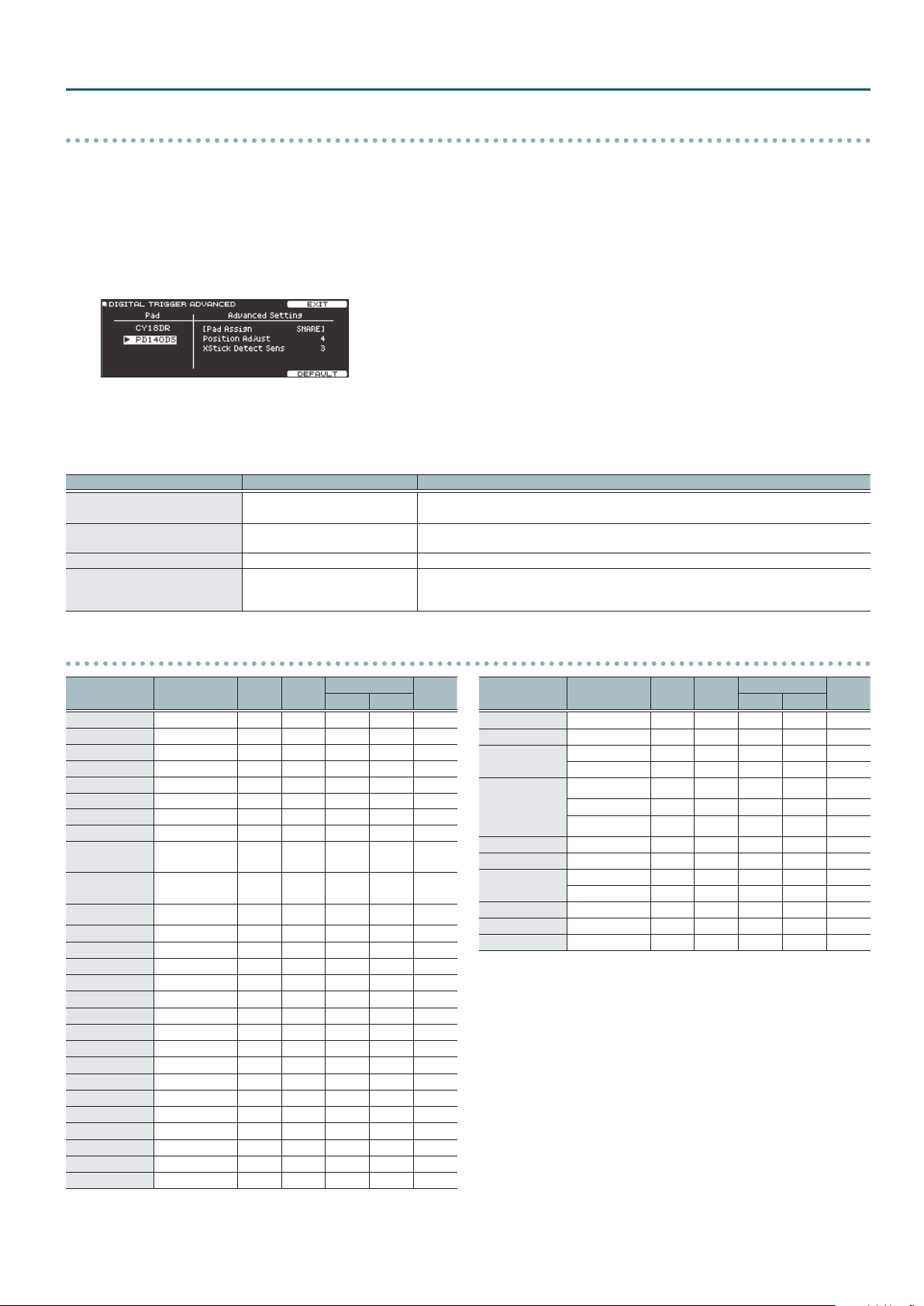
TRIGGER
Making detailed settings for digitally-connected pads
1. Press the [TRIGGER] button.
2. Press the PAGE [UP] button to access page 1 (TRIG BASIC).
3. Press the [F2] (DIGITAL) button.
4. Press the [F5] (ADVANCED) button.
The DIGITAL TRIGGER ADVANCED screen appears.
5. Use cursor buttons to select a parameter, and use the [–] [+] buttons or the dial to edit the value.
6. Press the [F4] (EXIT) button to return to the DIGITAL TRIGGER IN screen.
* The parameters that can be set dier depending on the type of pad.
Parameter Value Explanation
Position Adjust 1–10
XStick Detect Sens OFF, 1–5
Choke Sens OFF, 1–5 Adjusts the sensitivity of choking technique. If this is “OFF,” choking technique is unavailable.
Bell Gain 0–3.2
Adjusts how the tonal character is aected by strike position.
Lower values adjust toward the center, and higher values adjust toward the circumference.
Adjusts how easy it is to use cross-stick playing technique. If this is “OFF,” cross-stick technique is
unavailable.
Adjusts the balance between the force of a strike on the bell (bell shot technique) and the loudness
of the sound. With higher values of this setting, a high volume can be produced even by a soft
strike on the bell.
Trig Type list
Used modes Trig Type
KD-A22 KDA22 – – – – –
KD-140 KD140 – – – – –
KD-120 KD120 – – – – –
KD-85 KD85 – – – – –
KD-9 KD9 – – – – –
KD-8 KD8 – – – – –
KD-7 KD7 – – – – –
KT-10 KT10 – – – – –
PD-128S,
PD-128
PD-125XS,
PD-125X
PD-125 PD125
PD-108 PD108
PD-105X PD105X
PD-105 PD105
PD-85 PD85
PDX-100 PDX100
PDX-8 PDX8
PDX-6 PDX6
PD-8 PD8
VH-13 VH13
VH-12 VH12
VH-11 VH11
CY-15R CY15R
CY-14C CY14C
CY-13R CY13R
CY-12C CY12C
CY-12R/C CY12R/C
PD128
PD125X
Rim
shot
(
(
(
(
(
(
(
(
(
(
(
(
(
(
( ( (
(
( ( (
(
( ( (
Positional sensing
Bell
shot
Head Rim
( (
–
( (
–
( (
–
( (
–
( (
–
( (
–
( (
–
( (
–
– – – –
– – – –
– – –
– – –
– – –
– – –
–
(
–
–
–
–
(
–
–
Choke
play
Used modes Trig Type
CY- 8 CY8
CY- 5 CY5
BT-1
Generic pads
–
–
–
–
–
–
–
–
(
(
(
(
(
(
(
(
(
RT-30K RT30K – – – – –
RT-30HR RT30HR
RT-30H
RT-10K RT10K – – – – –
RT-10S RT10S
RT-10T RT10T – – – – –
*1 When using the BT-1, it is possible to further increase the sensitivity for soft strikes,
but this increases the possibility of unwanted triggering by vibration from the
surroundings.
*2 Select this if you attach an RT-30H to the snare.
*3 Select this if you attach an RT-30H to a tom.
BT1 – – – – –
BT1 SENS*1 – – – – –
PAD1
PAD2
PAD3
RT30H SN*2 – – – – –
RT30H TM*3 – – – – –
Rim
shot
(
(
(
(
(
(
(
Positional sensing
Bell
shot
Head Rim
– – –
– – –
– – –
– – – –
– – –
– – – –
– – – –
Choke
play
(
(
(
(
23
Page 24
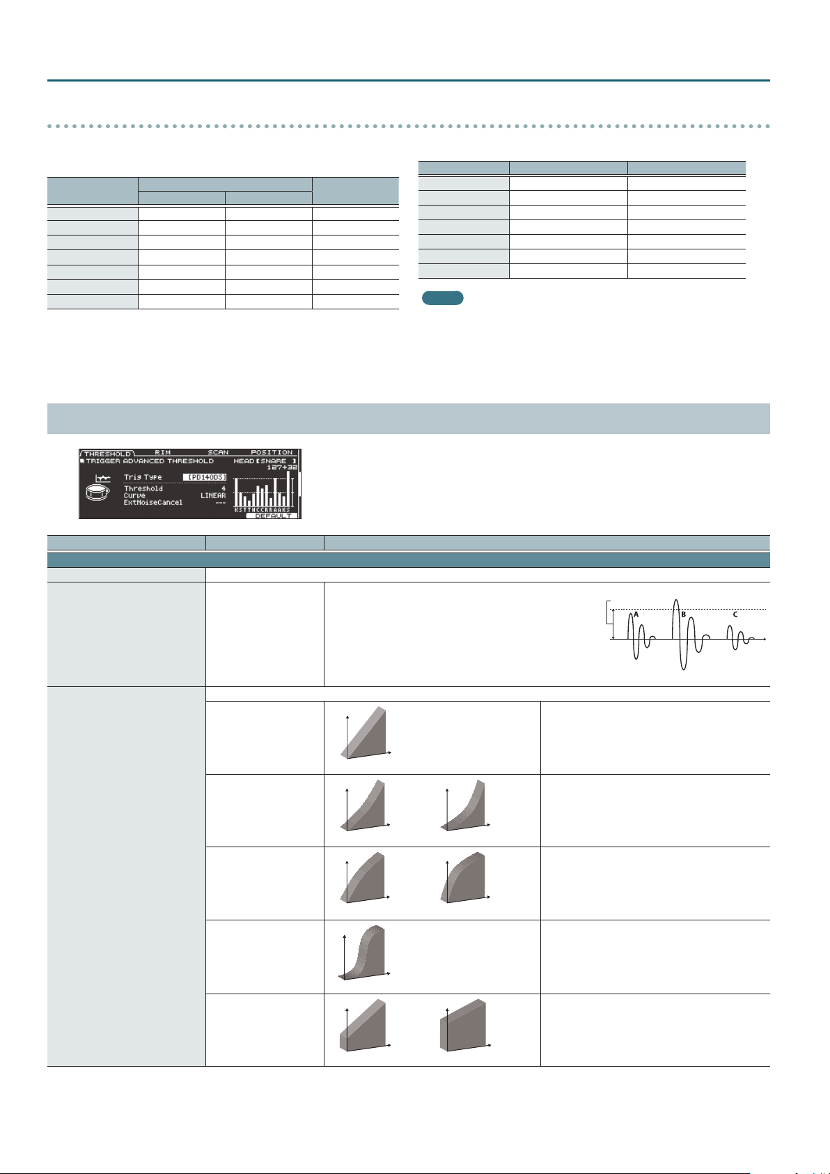
TRIGGER
LINEAR
EXP2EXP1
EXP2EXP1
LOG2LOG1
LOG2LOG1
SPLINE
LOUD2LOUD1
LOUD2LOUD1
Trigger inputs and playing methods corresponding chart
Rim shot/cross stick
* Use a dual-trigger type pad.
Trigger Input
KICK – – –
SNARE
TOM 1–4
HI-HAT
CRASH 1, 2
RIDE
AUX 1–4
Rubber Pad Mesh Pad
Rim Shot
( ( (
( (
(
(
(
( (
– –
– –
– –
Cross Stick
–
–
Positional sensing/rim shot nuance
Trigger Input Positional Sensing (Head) Rim Shot Nuance
KICK – –
SNARE
TOM 1–4
HI-HAT – –
CRASH 1, 2 – –
RIDE
AUX 1–4
MEMO
5 Brush sweep can be used only SNARE.
5 Each playing method can be used with the instruments corresponding to it.
5 Bell shots are possible only for “RIDE.”
5 Cross-stick is possible only for “SNARE.”
TRIG ADVANCED (page 2)
Parameter Value Explanation
THRESHOLD tab
Trig Type This is the same parameter as Trig Type (p. 22) in the BANK tab.
Minimum sensitivity of the pad
This setting allows a trigger signal to be received only when the
pad is above a determined force level (velocity). This can be used
Threshold 0–31
Volume change in response to pad strike strength
LINEAR
EXP1, EXP2
Curve
LOG1, LOG2
SPLINE
LOUD1, LOUD2
to prevent a pad from sounding because of vibrations from other
pads. In the following example, B will sound but A and C will not
sound.
Check this and adjust accordingly. Repeat this process until you get
the perfect setting for your playing style.
Volume
Playing
dynamics
Volume Volume
Playing
dynamics
Volume Volume
Playing
dynamics
Volume
Playing
dynamics
Volume Volume
Playing
dynamics
Playing
dynamics
Playing
dynamics
Playing
dynamics
( (
( (
(
( (
Threshold
The standard setting. This produces the most natural
correspondence between playing dynamics and
volume change.
Compared to “LINEAR,” strong dynamics produce a
greater change.
Compared to “LINEAR,” a soft playing produces a
greater change.
Extreme changes are made in response to playing
dynamics.
Very little dynamic response, making it easy to
maintain strong volume levels. If you’re using a drum
trigger as an external pad, these settings will produce
reliable triggering.
–
24
Page 25
Parameter Value Explanation
THRESHOLD tab
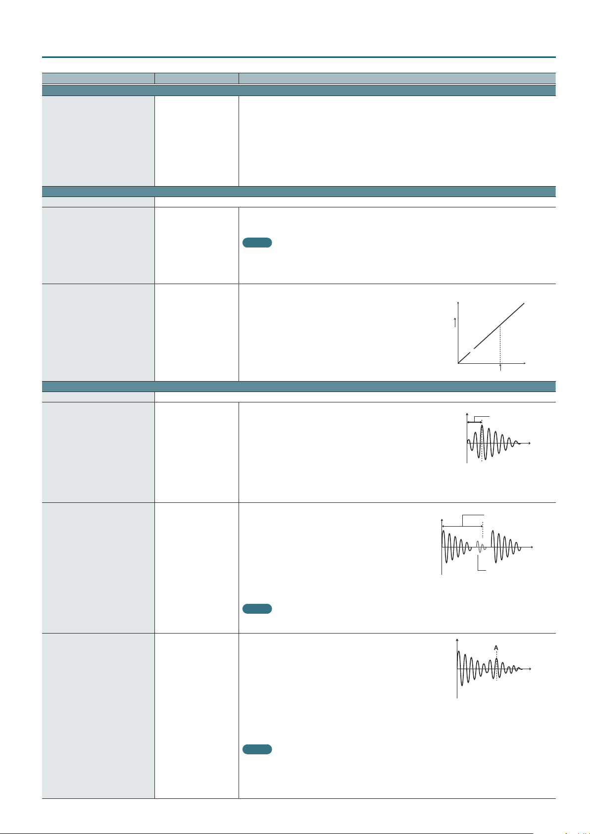
This setting lets you prevent a drum from being triggered unwantedly by a strike on a drum to which no
drum trigger is attached, or by sound or vibration from the surroundings (noise cancellation).
This noise cancel function can be used if you use a stereo cable to connect an “RT-30K” or “RT-30HR” drum
trigger to the following TRIGGER IN jacks and specify the Trig Type.
ExtNoiseCancel*1 OFF, 1–5
RIM tab
Trig Type This is the same parameter as Trig Type (p. 22) in the BANK tab.
Head/Rim Adjust*2 0–80
XStick Threshold*2 0–127
SCAN tab
Trig Type This is the same parameter as Trig Type (p. 22) in the BANK tab.
Scan Time 0–4.0 ms
Mask Time 0–64 ms
Supported TRIGGER IN jacks
5 KICK
5 SNARE
5 TOM1–4
5 AUX1–4
* The “RT-30H” does not support the noise cancel function.
If the rim sound is heard when you strike the head strongly, increase this value. If the head sound is heard
when you play an open rim shot, decrease this value. If the head sound is heard when you softly play a rim
shot, decrease this value.
MEMO
If the rim shot sound is heard when you play a head shot, or if a head shot sound is heard when you play
a rim shot, make small changes to the Head/Rim Adjust values while you continue trying out the results.
Extreme changes to the values will cause the wrong sound to be heard when you strike the pad, for
example producing the rim shot sound when you play a head shot.
For a pad that is connected to a TRIGGER IN jack, this species the force at which to switch between the cross
stick sound and open rim shot sound.
Setting this to a higher value makes it easier to get cross stick
sounds. When set to “0,” playing a cross stick produces the open rim
shot sound.
For a digitally connected pad that allows cross stick technique,
playing a cross stick with a strike that is stronger than the value of
this setting produces the open rim shot sound.
* For a pad that is connected to a TRIGGER IN jack, be aware that if
this value is raised excessively, the cross stick sound will also be
heard when you play an open rim shot.
Trigger signal detection time
Since the rise time of the trigger signal waveform may dier slightly
depending on the characteristics of each pad or acoustic drum trigger
(drum pickup), you may notice that identical hits (velocity) may produce
sound at dierent volumes. If this occurs, you can adjust the “Scan Time” so
that your way of playing can be detected more precisely.
While repeatedly hitting the pad at a constant force, gradually raise the Scan
Time value from 0 msec, until the resulting volume stabilizes at the loudest
level. At this setting, try both soft and loud strikes, and make sure that the volume changes appropriately.
* As the value is set higher, the time it takes for the sound to be played increases. Set this to the lowest value
possible.
Double triggering prevention
When playing a kick trigger the beater can bounce back and hit the
head a second time immediately after the intended note—with
acoustic drums sometimes the beater stays against the head—this
causes a single hit to “double trigger” (two sounds instead of one).
The Mask Time setting helps to prevent this. Once a pad has been
hit, any additional trigger signals occurring within the specied
“Mask Time” will be ignored.
Adjust the “Mask Time” value while playing the pad. When using a
kick trigger, try to let the beater bounce back and hit the head very
quickly, then raise the “Mask Time” value until there are no more sounds made by the beater rebound.
MEMO
If two or more sounds are being produced when you strike the head just once, then adjust Retrigger
Cancel.
Detecting trigger signal attenuation
Important if you are using acoustic drum triggers. Such triggers can
produce altered waveforms, which may also cause inadvertent sounding
at Point A in the following gure (Retrigger).
This occurs in particular at the decaying edge of the waveform. Retrigger
Cancel detects such distortion in and prevents retriggering from
occurring.
While repeatedly striking the pad, raise the “Retrigger Cancel” value until
Retrigger Cancel 1–16
retriggering no longer occurs.
Although setting this to a high value prevents retriggering, it then becomes easy for sounds to be omitted
when the drums played fast (roll etc.). Set this to the lowest value possible while still ensuring that there is no
retriggering.
MEMO
You can also eliminate this problem of retriggering with the Mask Time setting. Mask Time does not detect
trigger signals if they occur within the specied amount of time after the previous trigger signal was
received. Retrigger Cancel detects the attenuation of the trigger signal level, and triggers the sound after
internally determining which trigger signals were actually generated when the head was struck, while
weeding out the other false trigger signals that need not trigger a sound.
High
Low
Volume
Rim Shot
Sound
Cross Stick
Sound
XStick Threshold
Scan Time
Mask Time
Sound not produced
TRIGGER
Playing
dynamics
HardSoft
Time
Time
Time
25
Page 26
TRIGGER
Parameter Value Explanation
POSITION tab
Trig Type This is the same parameter as Trig Type (p. 22) in the BANK tab.
Positional sensing on/o
If you turn strike position detection on, you’ll be able to produce tonal change by varying the strike position on the head or by changing
Position Detect*2
Head OFF, ON Turns head strike position detection on/o
Rim OFF, ON Turns rim strike position detection on/o
*1 Only when Trig Type is set to “RT30K” or “RT30HR”
*2 For some Trig Type settings, this cannot be specied.
the nuance of your rim shots.
MEMO
To return to the default values, press the [F5] (DEFAULT) button.
The following parameters do not return to their default values when you change the Trig Type or press the [F5] (DEFAULT) button.
5 Hi-hat parameters
5 Oset
5 Foot Splash Sens
5 Noise Cancel
5 CC MAX
5 XStick Threshold
5 XTalk Cancel Rate
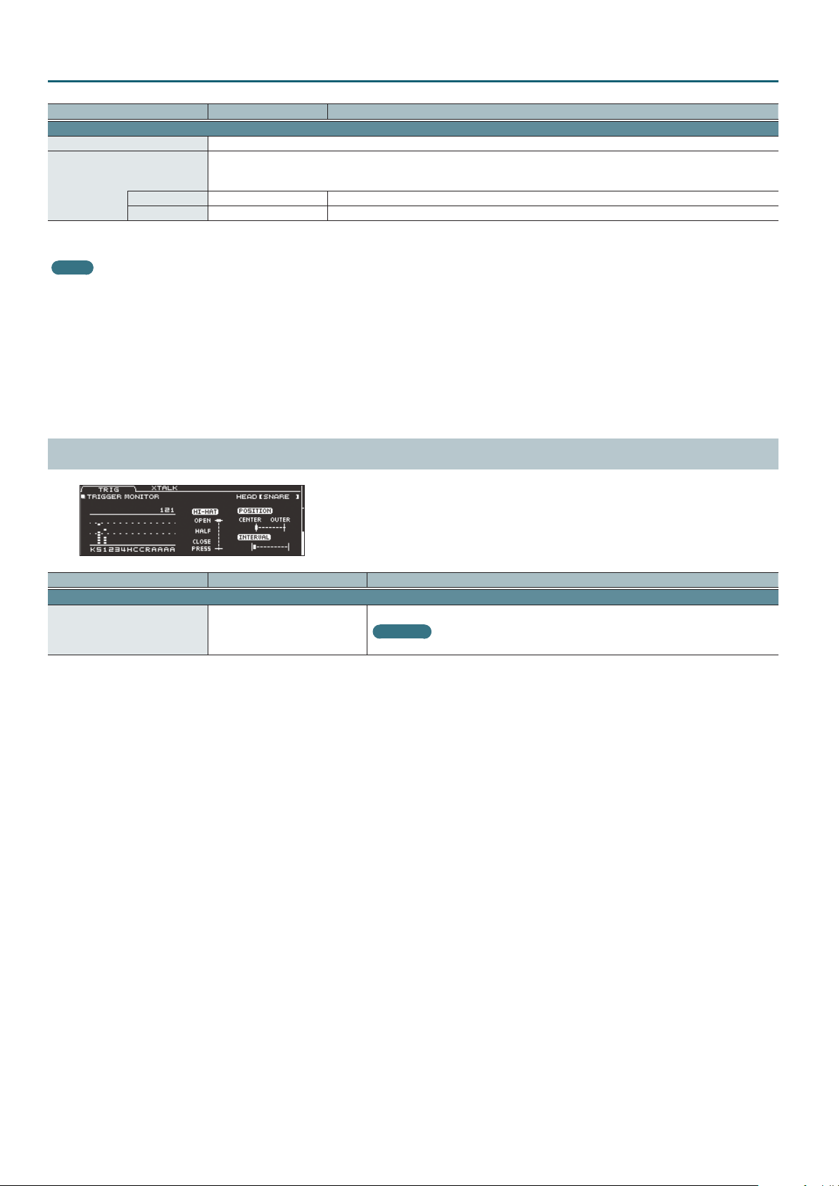
TRIG MONITOR (page 3)
Parameter Value Explanation
XTALK tab
Strength of crosstalk cancellation
XTalk Cancel Rate 0–80
Reference
For details on how to make these settings, refer to “Reference Manual.”
26
Page 27
SETUP
1. Press the [SETUP] button.
The SETUP MENU screen appears.
2. Use the PAGE [UP] [DOWN] buttons and the function buttons to select the setup menu that you want to edit.
Setup menu Explanation Page
OUTPUT Species the output destination of the sounds. p. 27
USB AUDIO Makes USB audio settings. p. 30
OPTION Makes settings for the [PREVIEW] button, the MIX IN jacks, and the display. p. 30
CONTROL Assigns functions to the footswitch and pads. p. 31
MIDI Makes MIDI settings. p. 32
AUTO OFF Makes AUTO OFF settings. p. 33
INFO Displays information about the TD-50 itself, such as the program version. p. 33
Returns the TD-50 to its factory settings.
FACTORY RESET
Reference
For details on the factory reset operation, refer to “Reference Manual” (PDF).
3. Edit the settings of the menu that you selected.
Reference
For details on operations in the setup menu, refer to “Reference Manual” (PDF).
–
OUTPUT
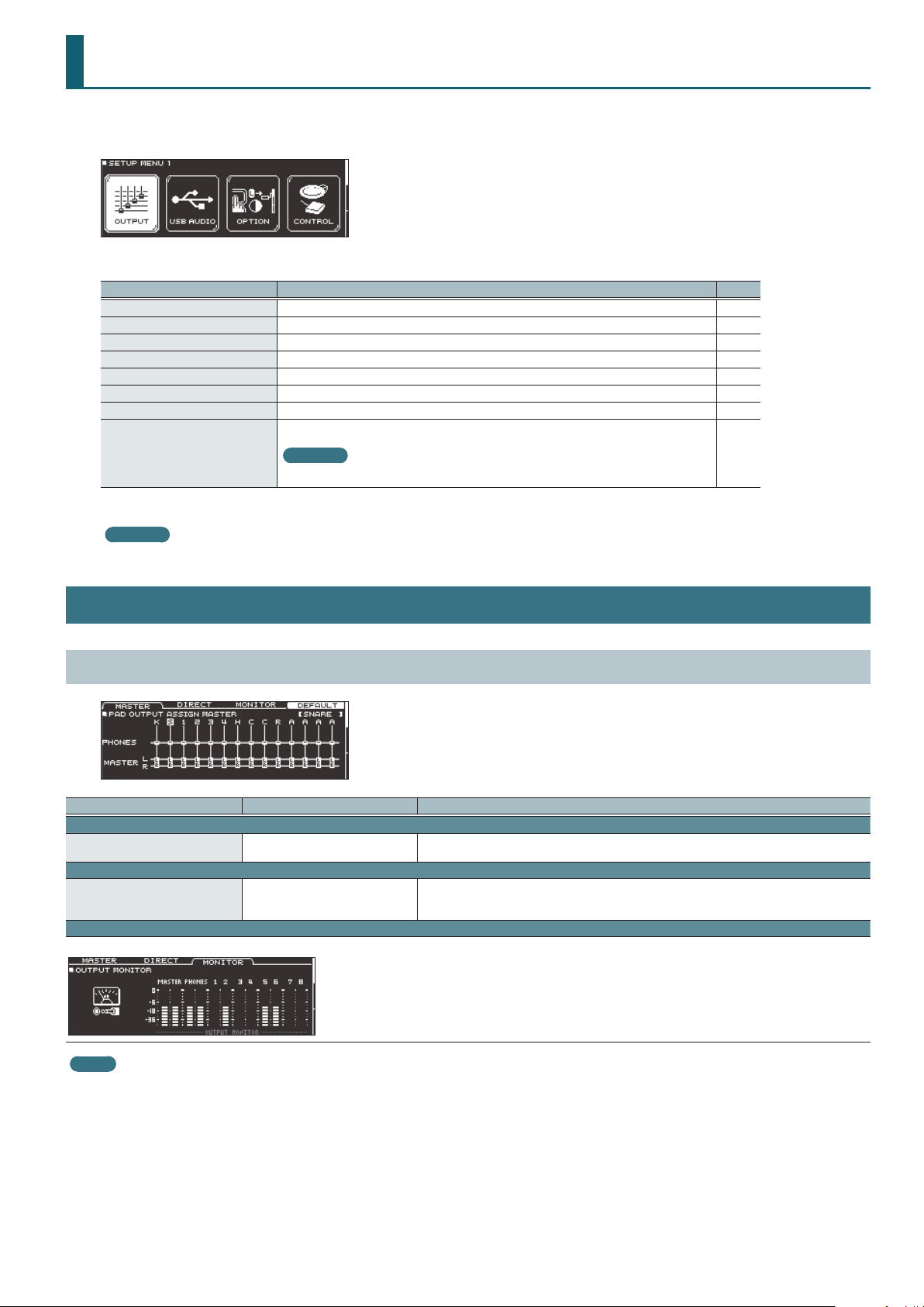
PAD OUTPUT (page 1)
Parameter Value Explanation
MASTER tab
PAD OUTPUT ASSIGN MASTER
DIRECT tab
PAD OUTPUT ASSIGN DIRECT
MONITOR tab
Monitor the output volume of each jack.
PHONES (MASTER OFF),
PHONES+MASTER LR
OFF, 1, 2, 1+2, 3, 4, 3+4, 5, 6, 5+6, 7,
8, 7+8, MASTER DIRECT L, MASTER
DIRECT R, MASTER DIRECT L+R
Species each pad’s output from the PHONES jacks and the MASTER OUT jacks (when Master Out
(p. 29) is “NORMAL”).
Species each pad’s output from the DIRECT OUT 1–8 jacks and the MASTER OUT jacks (when
Master Out (p. 29) is “DIRECT ”).
MEMO
If you want to return to the default values, press the [F4] (DEFAULT) button. If the [F2] (DIRECT ) button is selected, pressing the [F4] (DEFAULT) button lets you select the default
values (factory-set state) or an additional output setting (STEREO ALL) (supported starting with program version 1.05).
Use the cursor buttons to select “DEFAULT” if you want to return to the default values (factory-set state) or “STEREO ALL” if you want to select the other output setting; then press
the [F5] (RESET) button.
27
Page 28
SETUP
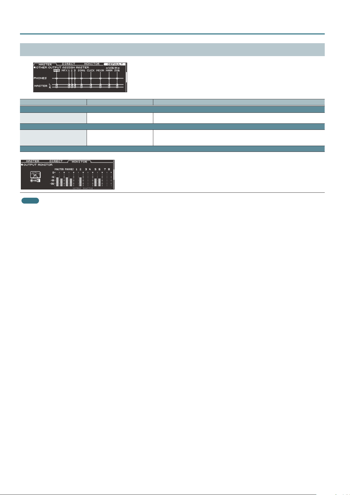
OTHER OUTPUT (page 2)
Parameter Value Explanation
MASTER tab
OTHER OUTPUT ASSIGN MASTER
DIRECT tab
OTHER OUTPUT ASSIGN DIRECT
MONITOR tab
Monitor the output volume of each jack.
PHONES (MASTER OFF),
PHONES+MASTER LR
OFF, 1, 2, 1+2, 3, 4, 3+4, 5, 6, 5+6, 7,
8, 7+8, MASTER DIRECT L, MASTER
DIRECT R, MASTER DIRECT L+R
MEMO
To return to the default values, press the [F4] (DEFAULT) button.
Species how ambience and MFX are output from the PHONES jacks and the MASTER OUT jacks
(when Master Out (p. 29) is “NORMAL”).
Species how ambience and MFX are output from the DIRECT OUT1–8 jacks and the MASTER OUT
jacks (when Master Out (p. 29) is “DIRECT ”).
28
Page 29
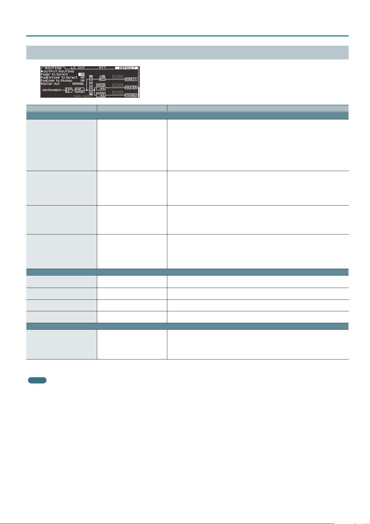
OUTPUT ROUTING (page 3)
Parameter Value Explanation
ROUTING tab
Species whether the fader values are applied to the output from the DIRECT OUT jacks (ON) or are
not applied (OFF).
If this is “OFF,” the output from the DIRECT OUT jacks is not aected by the panel faders.
If the OUTPUT ROUTING Master Out is “DIRECT,” and Fader to Direct is “OFF,” the output from the
Fader to Direct*1 OFF, ON
PadEq/Comp to Direct*1 OFF, ON
PadComp to Phones OFF, ON
Master Out*1 NORMAL, DIRECT
LO CUT tab
LoCut Frequency 20–200 Hz
DirectOut*2 OFF, ON
MasterOut*2 OFF, ON
PhonesOut OFF, ON
ATT tab
Direct Out Att*2 -12, -6, 0db
*1 This also applies to the TD-50’s sound that is output via USB audio.
*2 Low cut and attenuator do not apply to the TD-50’s sound that is output via USB audio.
MEMO
To return to the default values, press the [F4] (DEFAULT) button.
MASTER OUT jacks is also unaected by the panel faders.
Regardless of the Fader to Direct setting, the output from the PHONES jacks is always aected by
the panel faders.
This means that the faders at hand can be used to adjust the balance of the sound monitored by
the performer, independently of the balance adjusted by the PA.
Species whether the pad equalizer (p. 14) and pad compressor (p. 14) eects are applied (ON) or
are not applied (OFF) to the sound that is output from the DIRECT OUT jacks.
If this is “OFF,” the pad equalizer and pad compressor are bypassed for the output of the DIRECT
OUT jacks.
If the OUTPUT ROUTING Master Out is “DIRECT,” and PadEq/Comp to Direct is “OFF,” the output from
the MASTER OUT jacks also bypasses the pad equalizer and pad compressor.
Species whether the pad compressor (p. 14) is applied (ON) or is not applied (OFF) to the sound
that is output from the PHONES jacks.
If this is “OFF,” the pad compressor does not aect the output from the PHONES jacks.
For example, this lets you use the pad compressor to reduce the dynamic range for the drum
monitor or PA, but hear the full dynamics in the monitor headphones while you perform.
Selects whether the output of the MASTER OUT jacks is the same signal as the DIRECT OUT jacks
(DIRECT) or not (NORMAL).
If this is “DIRECT,” the output of the MASTER OUT jacks is not aected by the master compressor
and master EQ, allowing you to use the MASTER OUT jacks as DIRECT OUT jacks (the setting of the
[MASTER] knob does apply).
This setting also applies to the USB audio output to your computer.
Cuts the frequency region below the specied frequency (low cut).
This setting is common to all output jacks.
Species whether low cut is applied (ON) or is not applied (OFF) to the sound that is output from
the DIRECT OUT jacks.
Species whether low cut is applied (ON) or is not applied (OFF) to the sound that is output from
the MASTER OUT jacks.
Species whether low cut is applied (ON) or is not applied (OFF) to the sound that is output from
the PHONES jacks.
Lowers the volume of the DIRECT OUT jacks (attenuator).
This lets you decrease the volume if the output of the TD-50 is too high, causing distortion on the
device that receives these signals.
This applies to all DIRECT OUT jacks.
If Master Out is set to “DIRECT,” this also applies to the output from the MASTER OUT jacks.
SETUP
29
Page 30
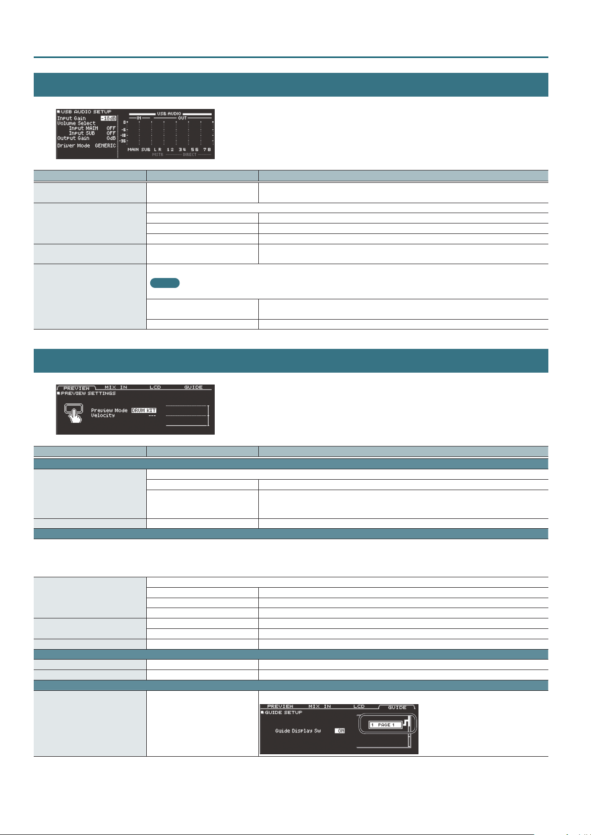
SETUP
USB AUDIO
Parameter Value Explanation
Input Gain -36–+12 dB
Species the knob that adjusts the input volume of USB audio (Input MAIN, SUB).
Volume Select
Input MAIN, SUB
Output Gain -24–+24 dB
OFF The volume is not adjusted by a knob.
SONG The [SONG] knob adjusts the volume.
CLICK The [CLICK] knob adjusts the volume.
Switches between the TD-50’s dedicated USB driver and the driver provided by your operating system.
MEMO
Driver Mode
The setting takes eect when the TD-50 is powered o and on again.
GENERIC
VENDOR Use the TD-50’s dedicated driver provided by Roland. USB MIDI and USB audio can be used.
Adjusts the input level
This setting is common to Input MAIN and SUB.
Adjusts the output level
This setting is common to all outputs.
Use the driver provided by the operating system.
Operation is limited to USB MIDI.
OPTION
Parameter Value Explanation
PREVIEW tab
Species how the sound is played when the [PREVIEW] button is pressed.
Preview Mode
Velocity 1–127+32 Velocity when Preview Mode is set to “FIXED”
MIX IN tab
The MIX IN jack can be used not only as a stereo input but also as mono input x2.
For example, if the click sound is being played through the L-channel of the MIX IN jack and the backing through the R-channel, set Mode to “MONO” so that the click and backing
are both heard from the center.
This setting is common to the front panel and rear panel MIX IN jacks.
Input
Mode
Gain 0, +6, +12 dB Adjusts the input level
LCD tab
Contrast 1–16 Display contrast
Brightness 1–16 Display brightness
GUIDE tab
FIXED The sound is heard at a xed volume regardless of how strongly the button is pressed.
DRUM KIT
Selects the jack(s) to use as an input.
L + R Use both channels
L ONLY Use only the left channel
R ONLY Use only the right channel
STEREO Use as stereo input
MONO Use as monaural x 2
The velocity changes depending on how strongly the button is pressed.
The velocity changes in the range of 1–127 according to the pad that is connected. For a digitally
connected pad, the velocity changes in the range of 1–127+32.
Species whether the guide is shown (ON) or not shown (OFF) on the screen when switching pages.
Guide Display Sw OFF, ON
30
Page 31
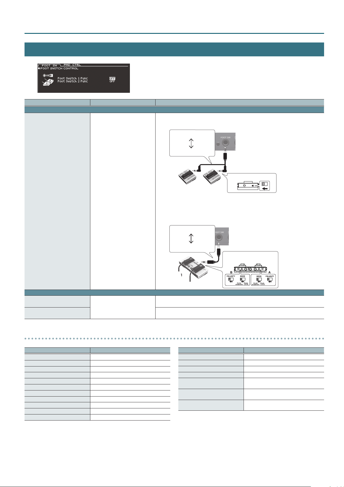
CONTROL
Parameter Value Explanation
FOOT SW tab
Assigns a function to a footswitch (separately sold: BOSS FS-5U, FS-6) connected to the TD-50.
Connecting an FS-5U
SETUP
Stereo 1/4” phone type
1/4” phone type x 2
Foot Switch 1 Func(SW1),
Foot Switch 2 Func(SW2)
PAD CTRL tab
Aux3 Head Func,
Aux3 Rim Func
Aux4 Head Func,
Aux4 Rim Func
See below
See below
RING
SW 2SW 1
TIP
POLARITY switch
* If you use a mono cable to connect a single FS-5U, it will operate as SW 2.
* The FS-5L cannot be used.
Connecting an FS-6
Stereo 1/4” phone type
Stereo 1/4” phone type
MODE/POLARITY switch
SW 1
SW 2
Assigns functions to a pad connected to TRIGGER IN jack 13/AUX3.
You can assign separate functions to the head and to the rim.
Assigns functions to a pad connected to TRIGGER IN jack 14/AUX4.
You can assign separate functions to the head and to the rim.
Functions that you can assign to a footswitch or pad
Value Explanation
OFF No function is assigned.
KIT# INC Calls up the previous kit.
KIT# DEC Calls up the next kit.
SETLIST# INC Calls up the previous set list.
SETLIST# DEC Calls up the next set list.
SONG# INC Calls up the previous song.
SONG# DEC Calls up the next song.
SONG PLAY Play the song.
SONG STOP Stop the song.
SONG TOP Return to the beginning of the song.
SONG PLAY/STOP Play/stop the song.
*1 If the trigger input (p. 22) of a digitally-connected pad (such as the PD-140DS) is assigned to snare, “XSTICK ON/OFF” has no eect.
Value Explanation
SONG AB REPEAT Species A-B repeat.
MFX 1 ON/OFF Turns on/o the multi-eect 1.
MFX 2 ON/OFF Turns on/o the multi-eect 2.
MFX 3 ON/OFF Turns on/o the multi-eect 3.
XSTICK ON/OFF*1
FIXED HH ON/OFF
ALL SOUND OFF
Switches between sounding or not sounding
the cross-stick sound.
Switches between setting the hi-hat Fixed
(p. 8) to “CLOSE” or not.
Stops the currently-sounding drum
performance sound or user sample playback.
31
Page 32
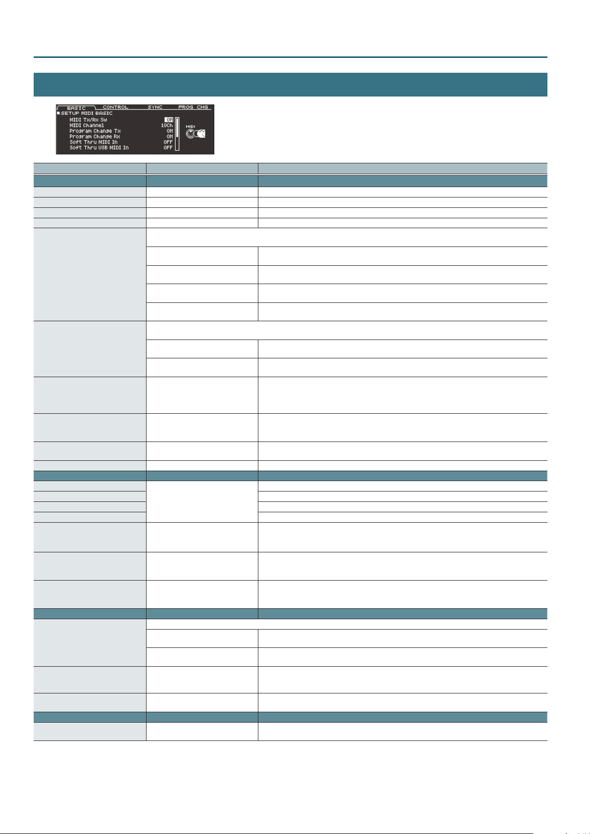
SETUP
MIDI
Parameter Value Explanation
BASIC tab
MIDI Tx/Rx Sw OFF, ON Turns the transmitting and receiving MIDI messages on/o.
MIDI Channel 1–16Ch Transmit and receive channel.
Program Change Tx OFF, ON Turns program change transmission on/o
Program Change Rx OFF, ON Turns program change reception on/o
This allows performance data from a MIDI device connected to the TD-50’s MIDI IN connector to be transmitted to another MIDI device
connected to the MIDI OUT connector or to a computer connected to the USB COMPUTER port.
OFF
Soft Thru MIDI In
Soft Thru USB MIDI In
Local Control OFF, ON
Device ID 17–32
Transmit Edit Data OFF, ON
Receive Exclusive OFF, ON Species whether system exclusive messages are received (ON) or not received (OFF).
CONTROL tab
HH Pedal CC
Snare CC Control change used for transmitting/receiving the strike position of the snare
Ride CC Control change used for transmitting/receiving the strike position of the ride
TOMs/AUXs CC Control change used for transmitting/receiving the strike position of the tom 1–4 and AUX 1–4
HH Note# Border 0–127
Hi-Reso Velocity OFF, ON
Cymbal Choke Shot OFF, ON
SYNC tab
Sync Mode
Clock Source MIDI, USB MIDI
Sync Out OFF, ON
PROG CHG tab
MIDI Program Change 1–127
ON (MIDI OUT)
ON (USB MIDI)
ON (MIDI+USB)
Performance data from a computer connected to the TD-50’s USB COMPUTER port can be transmitted to a MIDI device connected to the
MIDI OUT connector.
OFF
ON (MIDI OUT)
OFF, 1, 2, 4, 11, 16, 17, 18, 19
Species the synchronization signal according to which the TD-50 operates.
INTERNAL
EXTERNAL
Performance data received from the TD-50’s MIDI IN connector will not be sent to the MIDI OUT
connector or the USB COMPUTER port.
Performance data received from the TD-50’s MIDI IN connector will be sent to the MIDI OUT
connector.
Performance data received from the device connected to the TD-50’s MIDI IN connector will be sent
to the USB COMPUTER port.
Performance data received from the device connected to the TD-50’s MIDI IN connector will be sent
to the MIDI OUT connector and the USB COMPUTER port.
Performance data received via the TD-50’s USB COMPUTER port is not transmitted to the MIDI OUT
connector.
Performance data received via the TD-50’s USB COMPUTER port is transmitted to the MIDI OUT
connector.
Turns on/o the connection between the performance data from the pads and the TD-50’s sound
generator section
Normally you’ll leave this “ON.” If this is “OFF,” the performance data from the pads is not connected
to the TD-50’s sound generator section.
Device ID setting
The setting described here is necessary only when you wish to transmit separate data to two or
more TD-50 units at the same time. Do not change this setting in any other case.
Species whether changes in the TD-50’s settings are transmitted as system exclusive messages
(ON) or not transmitted (OFF).
Control change used for transmitting/receiving the depth to which the hi-hat pedal pressed
This number species the pedal position at which to switch from open hi-hat to closed hi-hat.
* There’s no need to change this setting if you’re performed and recording only with the TD-50
and the pads.
Disables CC#88 (high resolution velocity prex).
If this is disabled, the maximum velocity handled by the TD-50 is limited to 127. Velocity is also
limited to 127 for strikes on digitally-connected pads and for input via the MIDI IN connector.
Switches support for the performance technique of striking a pad while choking it.
If this is “ON,” striking a pad while choking it immediately mutes the sound after it begins. If this is
“OFF,” the sound is not muted immediately even if you strike a pad while choking it.
Choose this setting if you’re using the TD-50 by itself without synchronizing it to another device, or
if you want another device to operate in synchronization with the TD-50.
The TD-50 operates as a slave device. Choose this setting if you want the TD-50 to operate
according to synchronization messages that it receives from another device.
When Sync Mode is “EXTERNAL,” this species whether the TD-50 synchronizes to synchronization
messages from the MIDI IN connector (MIDI) or to synchronization messages from the USB
COMPUTER port (USB MIDI).
Species whether MIDI synchronization messages are transmitted to another device (ON) or not
transmitted (OFF).
You can freely specify the correspondence between drum kits and the program change numbers
that are transmitted and received.
32
Page 33
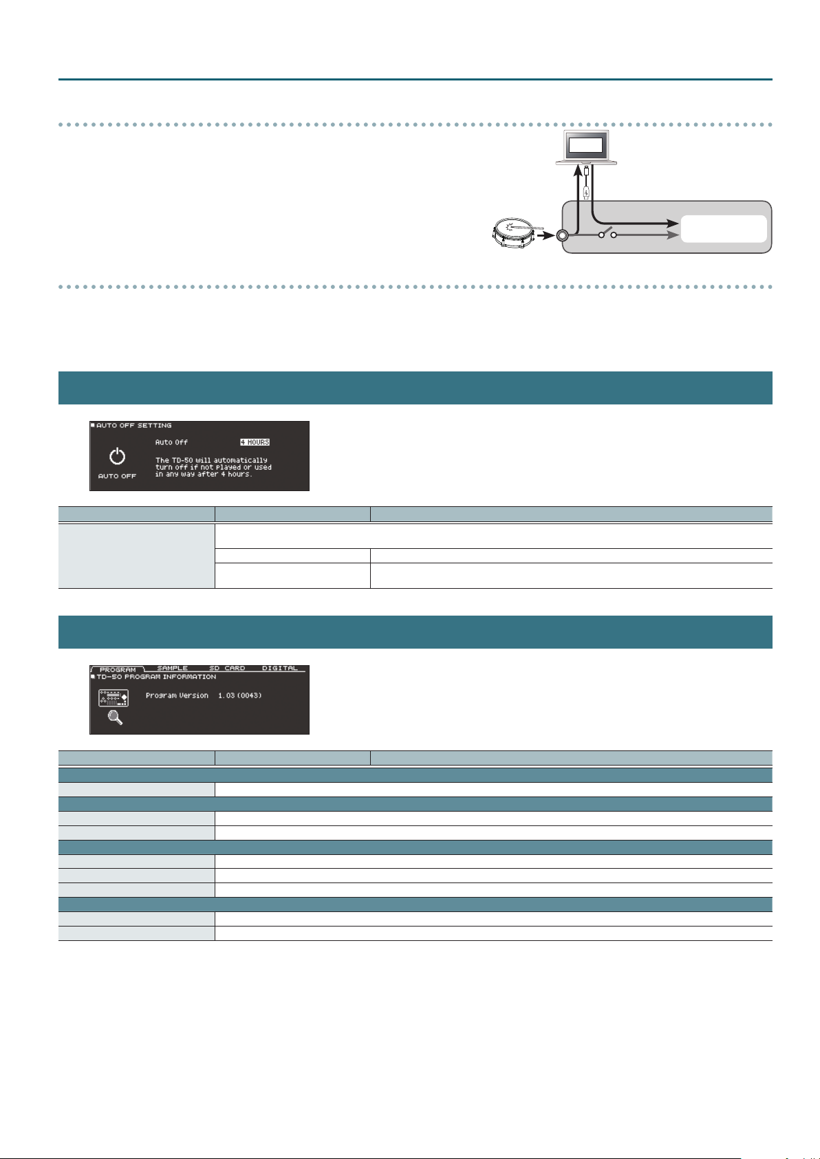
Using the Local Control setting
SETUP
If you’re using a DAW with the performance data from the pads and TD-50’s sound generator section, you
should turn the Local Control “OFF.” Here’s why.
We need to connect these sections in the following order: the performance data from the pads
a DAW0the TD-50’s sound generator section.
Since the performance data from the pads and TD-50’s sound generator section are connected internally,
such a connection order would normally be impossible. However, if the Local Control is “OFF,” the
performance data from the pads and TD-50’s sound generator section will be independent, allowing you to
use a DAW as shown here in the illustration.
0
Pad
DAW
TD-50
Local Control: OFF
Sound generator
section
Specifying the HH Note# Border
The note number transmitted when you strike the hi-hat will change depending on the amount of pressure on the hi-hat pedal.
At the factory default value (127), the closed hi-hat note number will be transmitted only if the hi-hat pad is played with the pedal completely depressed. If you want this note
number to be transmitted when the pedal is slightly raised, set this to a value such as “90.”
* In some cases, changing the hi-hat note number border setting might cause a song to play back dierently than when it was recorded.
AUTO OFF
Parameter Value Explanation
Species whether the unit will turn o automatically after a certain time has elapsed. If you don’t want the unit to turn o automatically,
choose “OFF” setting
Auto O
OFF The power does not turn o automatically.
4 HOURS
When four hours have elapsed without any pad being struck or any operation being performed, the
unit will turn o automatically.
INFO
Parameter Value Explanation
PROGRAM tab
Program Version Program version
SAMPLE tab
Imported Sample Number of imported user samples
Memory Remain Remaining amount for user samples in user memory
SD CARD tab
Backup All Backup data saved on the SD card (all settings)
1 Kit Kit backup data saved on the SD card
Rec Data Number of recorded data saved on the SD card
DIGITAL tab
Pad Indicates a pad that is digitally connected to the TD-50.
Program Version Indicates the program version of a pad that is digitally connected to the TD-50.
33
Page 34
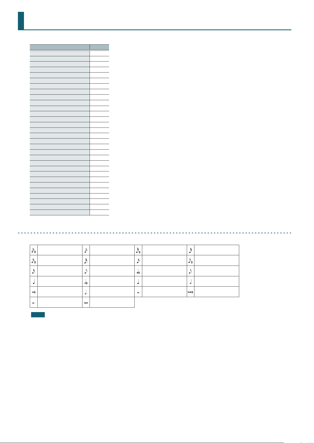
Multi-Eect Parameters
The multi-eects feature 30 dierent kinds of eects. Some of the eects consist of two or more dierent eects connected in series.
Eect type Page
DELAY p. 35
TAPE ECHO p. 35
REVERSE DELAY p. 35
3TAP PAN DELAY p. 35
OD0DELAY
DS0DELAY
CHORUS p. 36
SPACE-D p. 36
OD0CHORUS
DS0CHORUS
PHASER A p. 37
PHASER B p. 37
STEP PHASER p. 37
FLANGER p. 37
REVERB p. 38
LONG REVERB p. 38
SUPER FILTER p. 38
FILTER+DRIVE p. 38
AUTO WAH p. 39
OD/DS0TWA H
LOFI COMPRESS p. 39
DISTORTION p. 39
OVERDRIVE p. 39
SATURATOR p. 39
T-SCREAM p. 40
BIT CRUSHER p. 40
ISOLATOR p. 40
RING MODULATOR p. 40
PITCH SHIFTER p. 40
AUTO PAN p. 40
p. 36
p. 36
p. 36
p. 36
p. 39
About note values
Some eect parameters (such as Rate or Delay Time) can be set by using note values.
Sixty-fourth-note triplet Sixty-fourth note Thirty-second-note triplet Thirty-second note
Sixteenth-note triplet Dotted thirty-second note Sixteenth note Eighth-note triplet
Dotted sixteenth note Eighth note Quarter-note triplet Dotted eighth note
Quarter note Half-note triplet Dotted quarter note Half note
Whole-note triplet Dotted half note Whole note Double-note triplet
Dotted whole note Double note
NOTE
If you set the delay time as a note value, slowing down the tempo will not change the delay time beyond a certain length. There is an upper limit
for the delay time so if it is set as a note value and you slow down the tempo until this upper limit is reached, the delay time cannot change any
further. This upper limit is the maximum value that can be specied when setting the delay time as a numerical value.
34
Page 35
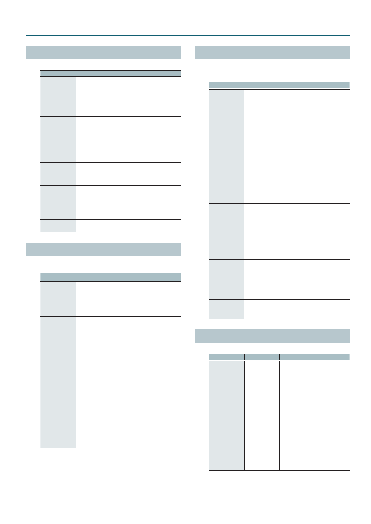
Multi-Eect Parameters
DELAY
This is a stereo delay.
Parameter Value Explanation
Tempo Sync Left,
Right
Delay Left, Right
Time
Phase Left, Right NORMAL, INVERSE Phase of the delay sound
Feedback Mode NORMAL, CROSS
Feedback -98–+98 %
HF Damp
Low Gain -15–+15 dB Gain of the low frequency range
High Gain -15–+15 dB Gain of the high frequency range
Level 0–127 Output Level
OFF, ON
1–1300 ms, note
200–8000
Hz, BYPASS
Species whether the delay time
value of the left/right delay sounds
is specied as a note value (ON) or
not (OFF).
Delay time from the original sound
until the left/right delay sound is
heard
Selects the way in which delay sound
is fed back into the eect
NORMAL: The left/right delay sounds
are fed back without modication.
CROSS: The left/right delay sounds
are alternately exchanged when fed
back.
Adjusts the amount of the delay
sound that’s fed back into the eect.
Negative “-” settings will invert the
phase.
Adjusts the frequency above which
sound fed back to the eect is
ltered out. If you don’t want to lter
out any high frequencies, set this
parameter to BYPASS.
TAPE ECHO
A virtual tape echo that produces a realistic tape delay sound. This
simulates the tape echo section of a Roland RE-201 Space Echo.
Parameter Value Explanation
Combination of playback heads to
use Select from three dierent heads
Mode
Repeat Rate 0–127
Intensity 0–127 Amount of delay repeats
Bass -15–+15 dB
Treble -15–+15 dB
Head S Pan L64–R63
Head M Pan L64–R63
Head L Pan L64–R63
Tape Distortion 0–5
W/F Rate 0–127
W/F Depth 0–127 Depth of wow/utter
Level 0–127 Output level
S, M, L, S+M, S+L,
M+L, S+M+L
with dierent delay times
S: Short
M: Middle
L: Long
Tape speed
Increasing this value will shorten the
spacing of the delayed sounds.
Boost/cut for the lower range of the
echo sound
Boost/cut for the upper range of the
echo sound
Independent stereo location for the
short, middle, and long playback
heads
Amount of tape-dependent
distortion to be added
This simulates the slight tonal
changes that can be detected by
signal-analysis equipment. Increasing
this value will increase the distortion.
Speed of wow/utter (complex
variation in pitch caused by tape
wear and rotational irregularity)
REVERSE DELAY
This is a reverse delay that adds a reversed and delayed sound to
the input sound. A tap delay is connected immediately after the
reverse delay.
Parameter Value Explanation
Threshold 0–127
Tempo Sync Rev OFF, ON
Rev Delay Time 1–1300 ms, note
Rev Delay
Feedback
Rev Delay HF
Damp
Rev Delay Pan L64–63R
Rev Delay Level 0–127 Volume of the reverse delay sound
Tempo Sync
Delay 1–3
Delay 1–3 Time 1–1300 ms, note
Delay 3 Feedback -98–+98 %
Delay HF Damp
Delay 1 Pan,
Delay 2 Pan
Delay 1 Level,
Delay 2 Level
Low Gain -15–+15 dB Gain of the low frequency range
High Gain -15–+15 dB Gain of the high frequency range
Level 0–127 Output Level
-98–+98 %
200–8000 Hz,
BYPASS
OFF, ON
200–8000 Hz,
BYPASS
L64–63R
0–127 Volume of the tap delay sounds
Volume at which the reverse delay
will begin to be applied
Species whether the delay time
value of the reverse delay is specied
as a note value (ON) or not (OFF).
Delay time from when sound is input
into the reverse delay until the delay
sound is heard
Proportion of the delay sound that
is to be returned to the input of the
reverse delay.
Negative “-” settings will invert the
phase.
Frequency at which the highfrequency content of the
reverse-delayed sound will be cut
(BYPASS: no cut)
Stereo location of the reverse delay
sound
Species whether the delay time
value of the tap delay is specied as a
note value (ON) or not (OFF).
Delay time from when sound is input
into the tap delay until the delay
sound is heard
Proportion of the delay sound that
is to be returned to the input of the
tap delay (negative values invert the
phase)
Frequency at which the high
frequency content of the tap delay
sound will be cut (BYPASS: no cut)
Stereo location of the tap delay
sounds
3TAP PAN DELAY
Produces three delay sounds; center, left and right.
Parameter Value Explanation
Tempo Sync Left,
Right, Center
Delay Left, Right,
Center Time
Center Feedback -98–+98 %
HF Damp
Left, Right,
Center Level
Low Gain -15–+15 dB Gain of the low frequency range
High Gain -15–+15 dB Gain of the high frequency range
Level 0–127 Output Level
OFF, ON
1–2600 ms, note
200–8000 Hz,
BYPASS
0–127 Volume of each delay
Species whether the delay time
value of the left/right/center delay
sound is specied as a note value
(ON) or not (OFF).
Adjusts the time until the delay
sound is heard.
Adjusts the amount of the delay
sound that’s fed back into the eect.
Negative “-” settings invert the phase.
Adjusts the frequency above which
sound fed back to the eect is
ltered out. If you do not want to
lter out any high frequencies, set
this parameter to BYPASS.
35
Page 36
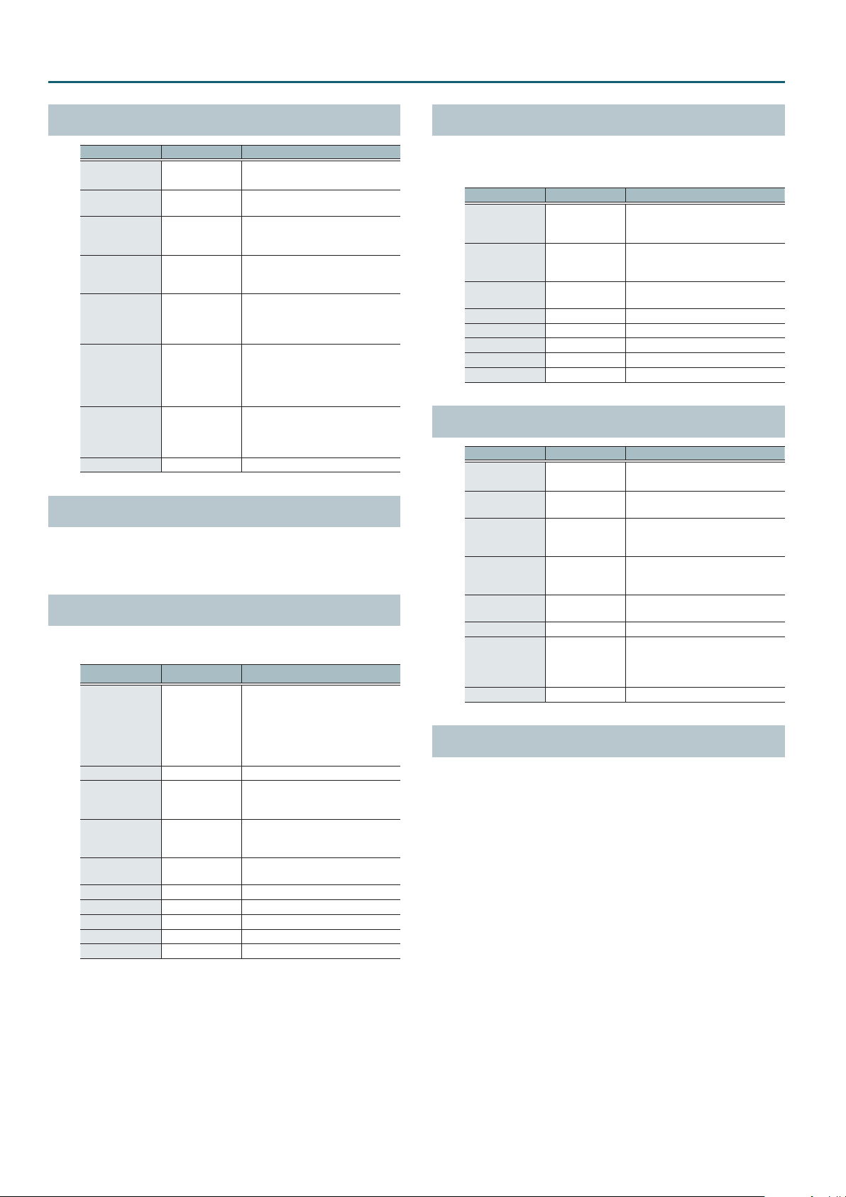
Multi-Eect Parameters
0
OD
DELAY
SPACE-D
Parameter Value Explanation
Overdrive Drive 0–127
Overdrive Pan L64–63R
Tempo Sync OFF, ON
Delay Time 1–2600 ms, note
Delay Feedback -98–+98 %
Delay HF Damp
Delay Balance
Level 0–127 Output Level
0
DS
DELAY
The parameters are essentially the same as in “OD0DELAY” with
the exception of the following two.
Overdrive Drive0Distortion Drive, Overdrive Pan0Distortion Pan
200–8000 Hz,
BYPASS
D100:0W–
D0:100W
Degree of distortion
Also changes the volume.
Stereo location of the overdrive
sound
Species whether the delay time
value of the delay is specied as a
note value (ON) or not (OFF).
Adjusts the delay time from the
direct sound until the delay sound
is heard.
Adjusts the proportion of the delay
sound that is fed back into the eect.
Negative “-” settings will invert the
phase.
Adjusts the frequency above which
sound fed back to the eect will be
cut. If you do not want to cut the
high frequencies, set this parameter
to BYPASS.
Adjusts the volume balance between
the sound that is sent through the
delay (W) and the sound that is not
sent through the delay (D).
CHORUS
This is a stereo chorus. A lter is provided so that you can adjust the
timbre of the chorus sound.
Parameter Value Explanation
Type of lter
OFF: no lter is used
Filter Type OFF, LPF, HPF
Cuto Freq 200–8000 Hz Basic frequency of the lter
Pre Delay 0.0–100.0 ms
Tempo Sync OFF, ON
Rate
Depth 0–127 Depth of modulation
Phase 0–180 deg Spatial spread of the sound
Low Gain -15–+15 dB Gain of the low range
High Gain -15–+15 dB Gain of the high range
Level 0–127 Output Level
0.05–10.00 Hz,
note
LPF: cuts the frequency range above
the Cuto Freq
HPF: cuts the frequency range below
the Cuto Freq
Adjusts the delay time from the
direct sound until the chorus sound
is heard.
Species whether the modulation
rate is specied as a note value (ON)
or not (OFF).
Frequency of modulation
This is a multiple chorus that applies two-phase modulation in
stereo. It gives no impression of modulation, but produces a
transparent chorus eect.
Parameter Value Explanation
Pre Delay 0.0–100.0 ms
Tempo Sync OFF, ON
Rate
Depth 0–127 Depth of modulation
Phase 0–180 deg Spatial spread of the sound
Low Gain -15–+15 dB Gain of the low range
High Gain -15–+15 dB Gain of the high range
Level 0–127 Output Level
0
OD
DS
CHORUS
Parameter Value Explanation
Overdrive Drive 0–127
Overdrive Pan L64–63R
Chorus Pre Delay 0.0–100.0 ms
Tempo Sync OFF, ON
Rate
Chorus Depth 0–127 Depth of modulation
Chorus Balance
Level 0–127 Output Level
0
CHORUS
The parameters are essentially the same as in “OD0CHORUS” with
the exception of the following two.
Overdrive Drive0Distortion Drive, Overdrive Pan0Distortion Pan
0.05–10.00 Hz,
note
0.05–10.00 Hz,
note
D100:0W–
D0:100W
Adjusts the delay time from the
direct sound until the chorus sound
is heard.
Species whether the modulation
rate is specied as a note value (ON)
or not (OFF).
Frequency of modulation
Degree of distortion
Also changes the volume.
Stereo location of the overdrive
sound
Adjusts the delay time from the
direct sound until the chorus sound
is heard.
Species whether the modulation
rate is specied as a note value (ON)
or not (OFF).
Frequency of modulation
Adjusts the volume balance between
the sound that is sent through the
chorus (W) and the sound that is not
sent through the chorus (D).
36
Page 37
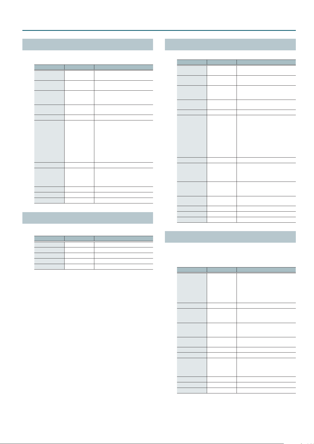
Multi-Eect Parameters
PHASER A
A phase-shifted sound is added to the original sound and
modulated.
Parameter Value Explanation
Mode
Manual 0–127
Tempo Sync OFF, ON
Rate
Depth 0–127 Depth of modulation
Polarity
Resonance 0–127 Amount of feedback
Cross Feedback -98–+98 %
Low Gain -15–+15 dB Gain of the low range
High Gain -15–+15 dB Gain of the high range
Level 0–127 Output Level
4-STAGE, 8-STAGE,
12-STAGE
0.05–10.00 Hz,
note
INVERSE,
SYNCHRO
Number of stages in the phaser
Adjusts the basic frequency from
which the sound will be modulated.
Species whether the modulation
rate is specied as a note value (ON)
or not (OFF).
Frequency of modulation
Selects whether the left and right
phase of the modulation will be the
same or the opposite.
INVERSE: The left and right phase
will be opposite. When using a mono
source, this spreads the sound.
SYNCHRO: The left and right phase
will be the same. Select this when
inputting a stereo source.
Adjusts the proportion of the phaser
sound that is fed back into the eect.
Negative “-” settings will invert the
phase.
PHASER B
STEP PHASER
The phaser eect will be varied gradually.
Parameter Value Explanation
Mode
Manual 0–127
Tempo Sync
(Rate)
Rate
Depth 0–127 Depth of modulation
Polarity
Resonance 0–127 Amount of feedback
Cross Feedback -98–+98 %
Tempo Sync
(Step Rate)
Step Rate
Low Gain -15–+15 dB Gain of the low range
High Gain -15–+15 dB Gain of the high range
Level 0–127 Output Level
4-STAGE, 8-STAGE,
12-STAGE
OFF, ON
0.05–10.00 Hz,
note
INVERSE,
SYNCHRO
OFF, ON
0.10–20.00 Hz,
note
Number of stages in the phaser
Adjusts the basic frequency from
which the sound will be modulated.
Species whether the modulation
rate is specied as a note value (ON)
or not (OFF).
Frequency of modulation
Selects whether the left and right
phase of the modulation will be the
same or the opposite.
INVERSE: The left and right phase
will be opposite. When using a mono
source, this spreads the sound.
SYNCHRO: The left and right phase
will be the same. Select this when
inputting a stereo source.
Adjusts the proportion of the phaser
sound that is fed back into the eect.
Negative “-” settings will invert the
phase.
Species whether the modulation
rate of the phaser eect is specied
as a note value (ON) or not (OFF).
Rate of the step-wise change in the
phaser eect
This simulates a dierent analog phaser than Phaser A.
Parameter Value Explanation
Speed 0–100 Frequency of modulation
Depth 0–127 Depth of modulation
Low Gain -15–+15 dB Gain of the low range
High Gain -15–+15 dB Gain of the high range
Level 0–127 Output Level
FLANGER
This is a stereo anger. (The LFO has the same phase for left and
right.) It produces a metallic resonance that rises and falls like a jet
airplane taking o or landing. A lter is provided so that you can
adjust the timbre of the anged sound.
Parameter Value Explanation
Type of lter
OFF: no lter is used
Filter Type OFF, LPF, HPF
Cuto Freq 200–8000 Hz Basic frequency of the lter
Pre Delay 0.0–100.0 ms
Tempo Sync OFF, ON
Rate
Depth 0–127 Depth of modulation
Phase 0–180 deg Spatial spread of the sound
Feedback -98–+98 %
Low Gain -15–+15 dB Gain of the low range
High Gain -15–+15 dB Gain of the high range
Level 0–127 Output Level
0.05–10.00 Hz,
note
LPF: cuts the frequency range above
the Cuto Freq
HPF: cuts the frequency range below
the Cuto Freq
Adjusts the delay time from when the
direct sound begins until the anger
sound is heard.
Species whether the modulation
rate is specied as a note value (ON)
or not (OFF).
Frequency of modulation
Adjusts the proportion of the anger
sound that is fed back into the eect.
Negative “-” settings will invert the
phase.
37
Page 38
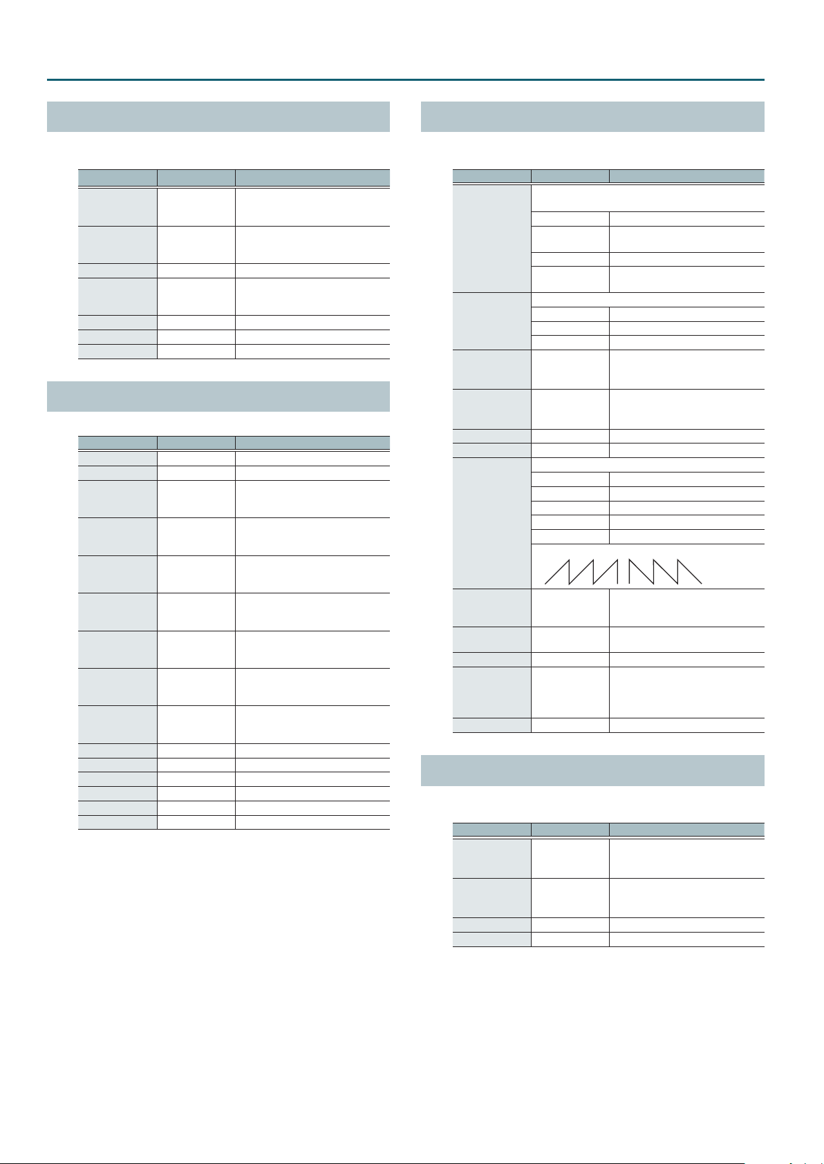
Multi-Eect Parameters
SAW1 SAW2
REVERB
Adds reverberation to the direct sound, simulating an acoustic
space.
Parameter Value Explanation
Type
Pre Delay 0.0–100 msec
Time 0–127 Time length of reverberation
HF Damp
Low Gain -15–+15 dB Gain of the low range
High Gain -15–+15 dB Gain of the high range
Level 0–127 Output Level
ROOM1, ROOM2,
STAGE1, STAGE2,
HALL1, HALL2
200–8000 Hz,
BYPASS
Type of reverb
Adjusts the delay time from the
direct sound until the reverb sound
is heard.
Adjusts the frequency above which
the reverberant sound will be cut
(BYPASS: no cut).
LONG REVERB
This is a very rich sounding reverb with a choice of character.
Parameter Value Explanation
Depth 0–127 Depth of the eect
Time 0–127 Time length of reverberation
Pre LPF
Pre HPF
Peaking Freq 200–8000 Hz
Peaking Gain -15–+15 dB
Peaking Q 0.5–8.0
HF Damp
LF Damp
Character 1–6 Type of reverb
EQ Low Freq 200–400 Hz Center frequency of the low region
EQ Low Gain -15–+15 dB Gain of the low range
EQ High Freq 2000–8000 Hz Center frequency of the high region
EQ High Gain -15–+15 dB Gain of the high range
Level 0–127 Output Level
16–15000 Hz,
BYPASS
BYPASS,
16–15000 Hz
16–15000 Hz,
BYPASS
BYPASS,
16–15000 Hz
Frequency of the lter that cuts the
high-frequency content of the input
sound (BYPASS: no cut)
Frequency of the lter that cuts the
low-frequency content of the input
sound (BYPASS: no cut)
Frequency of the lter that boosts/
cuts a specic frequency region of
the input sound
Amount of boost/cut produced by
the lter at the specied frequency
region of the input sound
Bandwidth of the lter that boosts or
cuts the specied frequency region
of the input sound
Frequency at which the highfrequency content of the resonant
sound will be cut (BYPASS: no cut)
Frequency at which the lowfrequency content of the resonant
sound will be cut (BYPASS: no cut)
SUPER FILTER
This is a lter with an extremely sharp slope. The cuto frequency
can be varied cyclically
Parameter Value Explanation
Filter type
Frequency range that will pass through each lter
LPF Frequencies below the cuto
Filter Type
Filter Slope
Filter Cuto 0–127
Filter Resonance 0–127
Filter Gain 0–+12 dB Amount of boost for the lter output
Modulation Sw OFF, ON On/o switch for cyclic change
Modulation Wave
Tempo Sync OFF, ON
Rate
Depth 0–127 Depth of modulation
Attack 0–127
Level 0–127 Output Level
BPF
HPF Frequencies above the cuto
NOTCH
Amount of attenuation per octave
-12 dB Gentle
-24 dB Steep
-36 dB Extremely steep
How the cuto frequency will be modulated
TRI Triangle wave
SQR Square wave
SIN Sine wave
SAW1 Sawtooth wave (upward)
SAW2 Sawtooth wave (downward)
0.05–10.00 Hz,
note
Frequencies in the region of the
cuto
Frequencies other than the region of
the cuto
Cuto frequency of the lter
Increasing this value will raise the
cuto frequency.
Filter resonance level
Increasing this value will emphasize
the region near the cuto frequency.
Species whether the modulation
rate is specied as a note value (ON)
or not (OFF).
Rate of modulation
Speed at which the cuto frequency
will change
This is eective if Modulation Wave is
SQR, SAW1, or SAW2.
FILTER+DRIVE
This is a low-pass lter equipped with overdrive. It cuts the upper
range and adds distortion.
Parameter Value Explanation
Cuto 0–127
Resonance 0–127
Drive 0–127 Amount of distortion
Level 0–127 Output Level
Cuto frequency of the lter
Increasing this value will raise the
cuto frequency.
Filter resonance level
Increasing this value will emphasize
the region near the cuto frequency.
38
Page 39
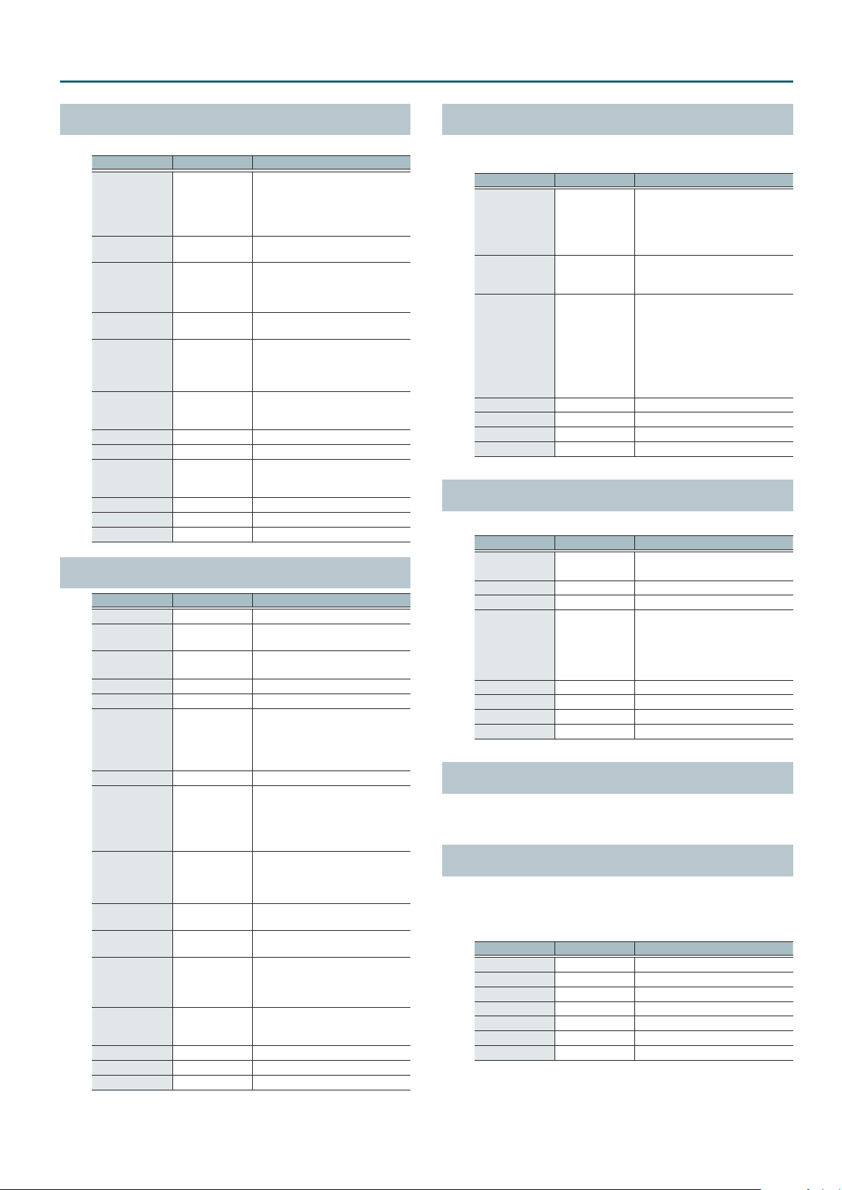
Multi-Eect Parameters
AUTO WAH
Cyclically controls a lter to create cyclic change in timbre.
Parameter Value Explanation
Type of lter
LPF: The wah eect will be applied
Filter Type LPF, BPF
Manual 0–127
Peak 0–127
Sens 0–127
Polarity UP, DOWN
Tempo Sync OFF, ON
Rate
Depth 0–127 Depth of modulation
Phase 0–180 deg
Low Gain -15–+15 dB Gain of the low range
High Gain -15–+15 dB Gain of the high range
Level 0–127 Output Level
OD/DS
0
Parameter Value Explanation
Drive Switch OFF, ON Turns overdrive/distortion on/o
Drive Type
Drive 0–127
Tone 0–127 Sound quality of the Overdrive eect
Amp Switch OFF, ON Turns the Amp Simulator on/o.
Amp Type
Touch Wah Switch
Touch Wah Mode LPF, BPF
Touch Wah
Polarity
Touch Wah Sens 0–127
Touch Wah
Manual
Touch Wah Peak 0–127
Touch Wah
Balance
Low Gain -15–+15 dB Gain of the low range
High Gain -15–+15 dB Gain of the high range
Level 0–127 Output Level
0.05–10.00 Hz, note
TWAH
OVERDRIVE,
DISTORTION
SMALL, BUILT-IN,
2-STACK, 3-STACK
OFF, ON Wah on/o
DOWN, UP
0–127
D100:0W–
D0:100W
over a wide frequency range.
BPF: The wah eect will be applied
over a narrow frequency range.
Adjusts the center frequency at
which the eect is applied.
Width of the frequency region at
which the wah eect is applied
Increasing this value will make the
frequency region narrower.
Adjusts the sensitivity with which the
lter is controlled.
Direction in which the lter will move
UP: Move toward a higher frequency
DOWN: Move toward a lower
frequency
Species whether the modulation
rate is specied as a note value (ON)
or not (OFF).
Frequency of modulation
Adjusts the degree of phase shift of
the left and right sounds when the
wah eect is applied.
Type of distortion
Degree of distortion
Also changes the volume.
Type of guitar amp
SMALL: small amp
BUILT-IN: single-unit type amp
2-STACK: large double stack amp
3-STACK: large triple stack amp
Type of lter
LPF: Produces a wah eect in a broad
frequency range.
BPF: Produces a wah eect in a
narrow frequency range.
Direction in which the lter will move
UP: Move toward a higher frequency
DOWN: Move toward a lower
frequency
Sensitivity with which the lter is
modied
Center frequency at which the wah
eect is applied
Width of the frequency region at
which the wah eect is applied
Increasing this value will make the
frequency region narrower.
Volume balance of the sound that
passes through the wah (W) and the
unprocessed sound (D)
LOFI COMPRESS
This is an eect that intentionally degrades the tone character for
creative purposes.
Parameter Value Explanation
Selects the type of lter applied to
the sound before it passes through
Pre Filter Type 1–6
LoFi Type 1–9
Post Filter Type OFF, LPF, HPF
Post Filter Cuto 200–8000 Hz Basic frequency of the Post Filter
Low Gain -15–+15 dB Gain of the low range
High Gain -15–+15 dB Gain of the high range
Level 0–127 Output Level
the Lo-Fi eect.
1: Compressor o
2–6: Compressor on
Degrades the tone character. The
tone character grows poorer as this
value is increased.
Selects the type of lter applied to
the sound after it passes through the
Lo-Fi eect.
OFF: no lter is used
LPF: cuts the frequency range above
the Cuto
HPF: cuts the frequency range below
the Cuto
DISTORTION
This is a distortion eect that provides heavy distortion.
Parameter Value Explanation
Drive 0–127
Tone 0–127 Sound quality of the Overdrive eect
Amp Sw OFF, ON Turns the Amp Simulator on/o.
Amp Type
Low Gain -15–+15 dB Gain of the low range
High Gain -15–+15 dB Gain of the high range
Pan L64–63R Stereo location of the output sound
Level 0–127 Output Level
SMALL, BUILT-IN,
2-STACK, 3-STACK
Degree of distortion
Also changes the volume.
Type of guitar amp
SMALL: small amp
BUILT-IN: single-unit type amp
2-STACK: large double stack amp
3-STACK: large triple stack amp
OVERDRIVE
This is an overdrive that provides heavy distortion. The parameters
are the same as for “DISTORTION.”
SATURATOR
A saturator which distorts the sound is connected in parallel with
a compressor, producing a rougher tonal character and boosting
the loudness. This also cuts the low-frequency region of the input
audio.
Parameter Value Explanation
Saturator Gain 0–127 Input volume to the saturator
Saturator Drive 0–127 Degree of distortion
Saturator Level 0–127 Output volume of the saturator
Comp Depth 0–127 Amount of compression
Comp Level 0–127 Output volume of the compressor
Hi Gain -12–+6 dB Gain of the high range
Level 0–127 Output Level
39
Page 40
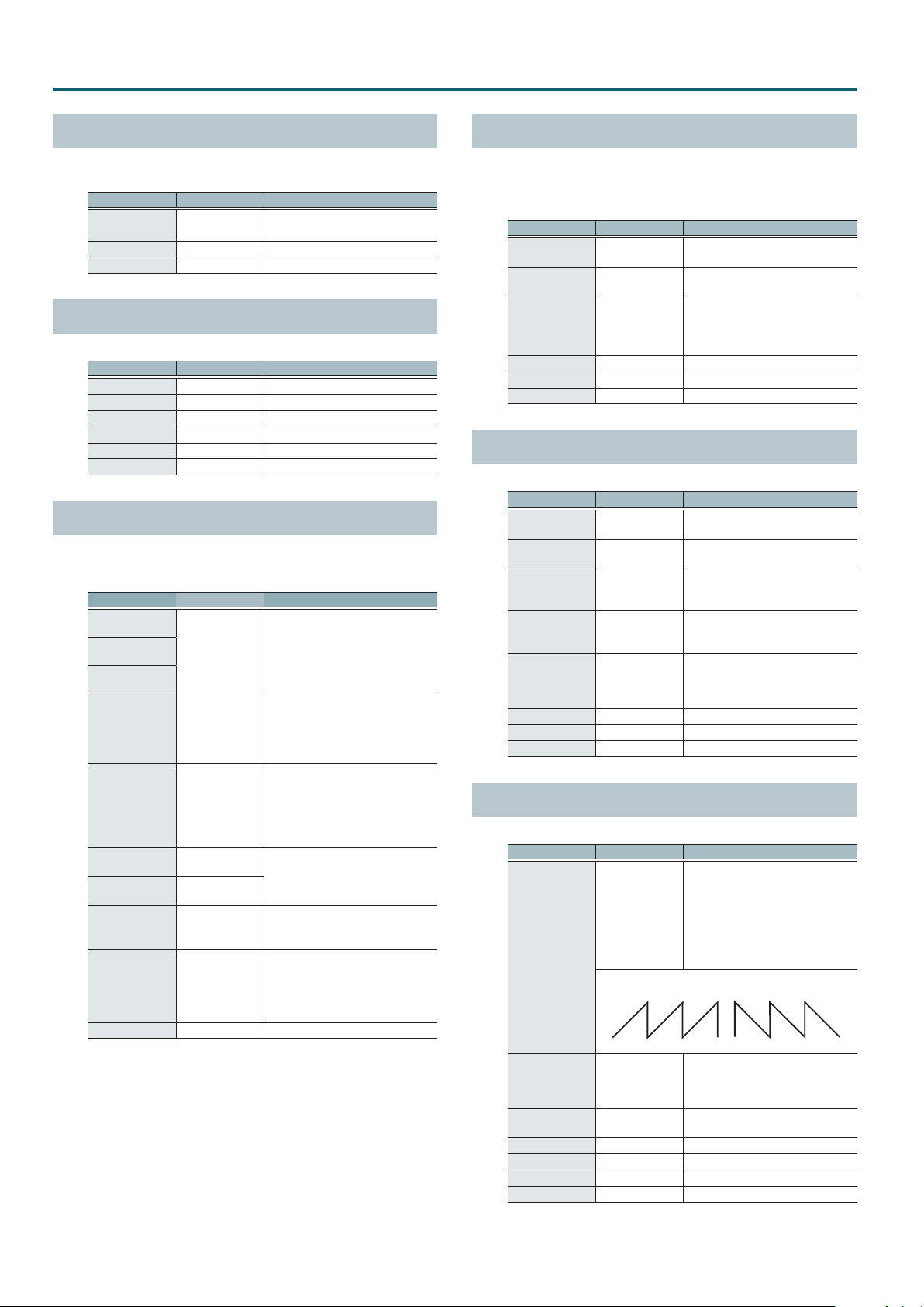
Multi-Eect Parameters
T-SCREAM
This models the analog overdrive of the past.
It adds a nice amount of overtones without dirtying the sound.
Parameter Value Explanation
Distortion 0–127
Tone 0–127 Sound quality of the Overdrive eect
Level 0–127 Output Level
Degree of distortion
Also changes the volume.
BIT CRUSHER
This creates a lo- sound.
Parameter Value Explanation
Sample Rate 0–127 Adjusts the sample rate.
Bit Down 0–18 Adjusts the bit depth.
Filter 0–127 Adjusts the lter depth.
Low Gain -15–+15 dB Gain of the low range
High Gain -15–+15 dB Gain of the high range
Level 0–127 Output Level
ISOLATOR
This is an equalizer which cuts the volume greatly, allowing you to
add a special eect to the sound by cutting the volume in varying
ranges.
Parameter Value Explanation
Boost/Cut Low
Boost/Cut Mid
Boost/Cut High
Anti Phase Low
Sw
Anti Phase Low
Level
Anti Phase Mid
Sw
Anti Phase Mid
Level
Low Boost Sw OFF, ON
Low Boost Level 0–127
Level 0–127 Output Level
-60–+4 dB
OFF, ON
0–127
OFF, ON
0–127
These boost and cut each of the
High, Middle, and Low frequency
ranges
At -60 dB, the sound becomes
inaudible. 0 dB is equivalent to the
input level of the sound.
Turns the Anti-Phase function on/o
for the Low frequency ranges
When turned on, the counterchannel of stereo sound is inverted
and added to the signal.
Adjusts the level settings for the Low
frequency ranges
Adjusting this level for certain
frequencies allows you to lend
emphasis to specic parts (This is
eective only for stereo source.).
Settings of the Anti-Phase function
for the Middle frequency ranges
The parameters are the same as for
the Low frequency ranges.
Turns Low Booster on/o
This emphasizes the bottom to create
a heavy bass sound.
Increasing this value gives you a
heavier low end
* Depending on the Isolator and
lter settings this eect may be
hard to distinguish.
RING MODULATOR
This is an eect that applies amplitude modulation (AM) to the
input signal, producing bell-like sounds. You can also change the
modulation frequency in response to changes in the volume of the
sound sent into the eect.
Parameter Value Explanation
Frequency 0–127
Sens 0–127
Polarity UP, DOWN
Low Gain -15–+15 dB Gain of the low range
High Gain -15–+15 dB Gain of the high range
Level 0–127 Output Level
Adjusts the frequency at which
modulation is applied.
Adjusts the amount of frequency
modulation applied.
Direction in which the frequency
modulation will move
UP: Towards higher frequencies
DOWN: Towards lower frequencies
PITCH SHIFTER
A stereo pitch shifter.
Parameter Value Explanation
Coarse -24–+12 semi
Fine -100–+100 cent
Tempo Sync OFF, ON
Delay Time 1–1300 ms, note
Feedback -98–+98 %
Low Gain -15–+15 dB Gain of the low range
High Gain -15–+15 dB Gain of the high range
Level 0–127 Output Level
Adjusts the pitch of the pitch shifted
sound in semitone steps.
Adjusts the pitch of the pitch shifted
sound in 2-cent steps.
Species whether the delay time
value of the delay is specied as a
note value (ON) or not (OFF).
Adjusts the delay time from the
direct sound until the pitch shifted
sound is heard.
Adjusts the proportion of the pitch
shifted sound that is fed back into
the eect. Negative “-” settings will
invert the phase.
AUTO PAN
Cyclically modulates the stereo location of the sound.
Parameter Value Explanation
Modulation wave
TRI: Triangle wave
TRI, SQR, SIN,
SAW1, SAW2, TRP
Mod Wave
SAW1 SAW2
R R
L L
Tempo Sync OFF, ON
Rate
Depth 0–127 Depth to which the eect is applied
Low Gain -15–+15 dB Gain of the low range
High Gain -15–+15 dB Gain of the high range
Level 0–127 Output Level
0.05–10.00 Hz,
note
SQR: Square wave
SIN: Sine wave
SAW1: Sawtooth wave (upward)
SAW2: Sawtooth wave (downward)
TRP: Trapezoidal wave
Species whether the rate of
modulation applied to the eect is
specied as a note value (ON) or not
(OFF).
Frequency of the change
40
Page 41
Drum Kit List
No. Drum kit name Sub name
1 Jarrah Ply Hardwood
2 Rock Legend Studio"LiveRoom"
3 STUDIO B Med/Stone Wall
4 WalnutPopper Compact Kit
5 Power Metal
6 Rootsy Funk
7 BubingaBoom
8 FAT+808 RnB,HipHop Style
9 Perc Tribe Pedal:Pitch Bend
10 Beatnik Processed Hybrid
11 STUDIO A Large/Hi Celling
12 Stainless 70’s Vintage
13 Second Line New Orleans
14 Heavy Prog
15 Blues Club
16 JarrahFunk Contemporary
17 MuterBeat
18 Loop-U-Lator Ring Modulator
19 Cosmic Pop w/ Super Saw
20 Trash Noiser
21 Drum Booth Med/Cloth Wall
22 BigBeat Rock
23 Waxy Jazz Bebop Style
24 GroovePopper
25 Hard Rock 80’s/90’s
26 Moon Walk Tape Echo
27 Bubinga w/ 80’sBeechS
28 Hybrid DnB
29 Funky Fat Overdrive
30 TrashElectro 2nd Hi-Hat
31 Studio LiveRoom Session
32 Phasin’ Rock
33 Round Badge 60’s Vintage
34 80’s Studio Deep Shell Toms
35 ShallowShell w/ ProtoChinaCym
36 Roots Reggae w/ Timbales
37 RingingTones No Muing
38 Warm Groove
39 Jazz Hop Compact Kit
40 ExtremeMetal Lo-Fi Compress
41 Verb Ballad w/ Percussion
42 DownUnder West Coast
43 60/70’s Hit
44 Dance Beats Old School
45 House=909 2nd Hi-Hat
46 Ana Hybrid Flanger&Phaser
47 Short Tail Melodic Toms
48 Unplugged Cajon CompactKit
49 +Latin Perc w/ Tambourine HH
50 Laboratory Sound Textures
51 User Kit
52 User Kit
53 User Kit
54 User Kit
55 User Kit
56 User Kit
57 User Kit
58 User Kit
59 User Kit
60 User Kit
61 User Kit
62 User Kit
63 User Kit
64 User Kit
65 User Kit
66 User Kit
67 User Kit
68 User Kit
69 User Kit
No. Drum kit name Sub name
70 User Kit
71 User Kit
72 User Kit
73 User Kit
74 User Kit
75 User Kit
76 User Kit
77 User Kit
78 User Kit
79 User Kit
80 User Kit
81 User Kit
82 User Kit
83 User Kit
84 User Kit
85 User Kit
86 User Kit
87 User Kit
88 User Kit
89 User Kit
90 User Kit
91 User Kit
92 User Kit
93 User Kit
94 User Kit
95 User Kit
96 User Kit
97 User Kit
98 User Kit
99 User Kit
100 User Kit
41
Page 42
Instrument List
No. Instrument name Instrument group Remarks
0 OFF OFF
1 Jarrah Ply K KICK A *M1 *T
2 MapleWlnutChrryK KICK A *M1 *T
3 Birch 18" K KICK A *M1 *T
4 Bubinga 9Ply K KICK A *M1 *T
5 60sRoundBdge20"K KICK A *M1 *T
6 70s Maple 24" K KICK A *M1 *T
7 70sStainless24"K KICK A *M1 *T
8 Tight Kick 1 KICK PROC
9 Tight Kick 2 KICK PROC
10 Tight Kick 3 KICK PROC
11 Impact Kick KICK PROC
12 Hybrid Kick KICK PROC
13 Tronic Kick KICK PROC
14 Electro Knock K KICK PROC
15 Minimal House K KICK PROC
16 Early House Kick KICK PROC
17 BreakBeats Kick1 KICK PROC
18 BreakBeats Kick2 KICK PROC
19 DnB Kick 1 KICK PROC
20 DnB Kick 2 KICK PROC
21 Nu Hip Kick KICK PROC
22 Lo-Fi Kick KICK PROC
23 Hi Jumper Kick KICK PROC
24 Lo Jumper Kick KICK PROC
25 Dance Kick KICK PROC
26 Dancer Kick KICK PROC
27 Voice Kick 1 KICK PROC
28 Voice Kick 2 KICK PROC
29 Analog Kick 1 KICK ELEC
30 Analog Kick 2 KICK ELEC
31 Analog Kick 3 KICK ELEC
32 CR-78 Kick KICK ELEC
33 TR-606 Kick KICK ELEC
34 TR-808 Kick 1 KICK ELEC
35 TR-808 Kick 2 KICK ELEC
36 TR-808 Kick Long KICK ELEC
37 TR-909 Kick 1 KICK ELEC
38 TR-909 Kick 2 KICK ELEC
39 TR-909 Kick 3 KICK ELEC
40 DR-110 Kick KICK ELEC
41 R-8 Kick KICK ELEC
42 Jarrah Ply S SNARE A *P *M1 *X *T *D
43 Jarrah Ply SR SNARE A *P *M1 *X *T *D
44 MapleOilFinish S SNARE A *P *M1 *X *T *D
45 MapleOilFinishSR SNARE A *P *M1 *X *T *D
46 80sBeech 12Ply S SNARE A *P *M1 *X *T *D
47 80sBeech12Ply SR SNARE A *P *M1 *X *T *D
48 Steel TubeLugs S SNARE A *P *M1 *X *T *D
49 SteelTubeLugs SR SNARE A *P *M1 *X *T *D
50 WalnutPopper12"S SNARE A *P *M1 *X *T *D
51 WalnutPoper12"SR SNARE A *P *M1 *X *T *D
52 Jarrah Ply X CROSS STICK *M1 *X *T
53 MapleOilFinish X CROSS STICK *M1 *X *T
54 80sBeech 12Ply X CROSS STICK *M1 *X *T
55 Steel TubeLugs X CROSS STICK *M1 *X *T
56 WalnutPopper12"X CROSS STICK *M1 *X *T
57 OldSchool Snare SNARE PROC
58 DnB Snare SNARE PROC
59 Dub Step Snare SNARE PROC
60 Disto Slap Snare SNARE PROC
61 House Low Snare SNARE PROC
No. Instrument name Instrument group Remarks
62 Hip Snare SNARE PROC
63 Garage Snare SNARE PROC
64 Radio Snare SNARE PROC
65 Voice Snare SNARE PROC
66 Voice CrossStick SNARE PROC
67 Analog Snare 1 SNARE ELEC
68 Analog Snare 2 SNARE ELEC
69 CR-78 Snare SNARE ELEC
70 TR-808 Snare 1 SNARE ELEC
71 TR-808 Snare 2 SNARE ELEC
72 TR-909 Snare SNARE ELEC
73 TR-909 S w/ Clap SNARE ELEC
74 TR-606 Snare SNARE ELEC
75 TR-707 Snare SNARE ELEC
76 DR-110 Snare SNARE ELEC
77 CR-78 Rim SNARE ELEC
78 TR-808 Rim SNARE ELEC
79 TR-909 Rim SNARE ELEC
80 Jarrah Ply 8" TOM A *M1 *T
81 Jarrah Ply 8" R TOM A *P *M1 *T
82 Jarrah Ply 10" TOM A *M1 *T
83 Jarrah Ply 10" R TOM A *P *M1 *T
84 Jarrah Ply 12" TOM A *M1 *T
85 Jarrah Ply 12" R TOM A *P *M1 *T
86 Jarrah Ply 14" TOM A *M1 *T
87 Jarrah Ply 14" R TOM A *P *M1 *T
88 Jarrah Ply 16" TOM A *M1 *T
89 Jarrah Ply 16" R TOM A *P *M1 *T
90 Bubinga 9Ply 10" TOM A *M1 *T
91 Bubinga9Ply10" R TOM A *P *M1 *T
92 Bubinga 9Ply 12" TOM A *M1 *T
93 Bubinga9Ply12" R TOM A *P *M1 *T
94 Bubinga 9Ply 14" TOM A *M1 *T
95 Bubinga9Ply14" R TOM A *P *M1 *T
96 Bubinga 9Ply 16" TOM A *M1 *T
97 Bubinga9Ply16" R TOM A *P *M1 *T
98 60sRoundBadge13" TOM A *M1 *T
99 60sRoundBdge13"R TOM A *P *M1 *T
100 60sRoundBadge16" TOM A *M1 *T
101 60sRoundBdge16"R TOM A *P *M1 *T
102 70sStainless 12" TOM A *M1 *T
103 70sStainless12"R TOM A *P *M1 *T
104 70sStainless 13" TOM A *M1 *T
105 70sStainless13"R TOM A *P *M1 *T
106 70sStainless 16" TOM A *M1 *T
107 70sStainless16"R TOM A *P *M1 *T
108 70sStainless 18" TOM A *M1 *T
109 70sStainless18"R TOM A *P *M1 *T
110 Gong Drum 20" TOM A *M1 *T
111 Analog Tom1 T1 TOM ELEC
112 Analog Tom1 T2 TOM ELEC
113 Analog Tom1 T3 TOM ELEC
114 Analog Tom1 T4 TOM ELEC
115 Analog Tom2 T1 TOM ELEC
116 Analog Tom2 T2 TOM ELEC
117 Analog Tom2 T3 TOM ELEC
118 Analog Tom2 T4 TOM ELEC
119 TR-808 Tom T1 TOM ELEC
120 TR-808 Tom T2 TOM ELEC
121 TR-808 Tom T3 TOM ELEC
122 TR-808 Tom T4 TOM ELEC
123 TR-909 Tom T1 TOM ELEC
42
Page 43
Instrument List
No. Instrument name Instrument group Remarks
124 TR-909 Tom T2 TOM ELEC
125 TR-909 Tom T3 TOM ELEC
126 TR-909 Tom T4 TOM ELEC
127 Trad Lathed HH HI-HAT *M2 *T
128 Trad Lathed HHE HI-HAT *M2 *T
129 Dark&Warm HH HI-HAT *M2 *T
130 Dark&Warm HHE HI-HAT *M2 *T
131 Club Hi-Hat HI-HAT PROC
132 Sharp Hi-Hat HI-HAT PROC
133 Hip Hi-Hat HI-HAT PROC
134 House Hi-Hat HI-HAT PROC
135 DnB Hi-Hat HI-HAT PROC
136 LowStep Hi-Hat HI-HAT PROC
137 Voice Hi-Hat HI-HAT PROC
138 Spoke Hi-Hat HI-HAT PROC
139 CR-78 Hi-Hat HI-HAT ELEC
140 TR-808 Hi-Hat HI-HAT ELEC
141 TR-909 Hi-Hat HI-HAT ELEC
142 Trad MedThin Rd RIDE *P *M2 *T
143 Trad MedThin RdE RIDE *M2 *T
144 Trad MedThin RdB RIDE *M2 *T
145 Dry & Heavy Rd RIDE *P *M2 *T
146 Dry & Heavy RdE RIDE *M2 *T
147 Dry & Heavy RdB RIDE *M2 *T
148 Trad Thin Cr CRASH *M2 *T
149 Trad Thin CrE CRASH *M2 *T
150 Warm MedThin Cr CRASH *M2 *T
151 Warm MedThin CrE CRASH *M2 *T
152 Silvery Cr CRASH *M2 *T
153 Silvery CrE CRASH *M2 *T
154 Legacy Thin Cr CRASH *M2 *T
155 Legacy Thin CrE CRASH *M2 *T
156 Power Medium Cr CRASH *M2 *T
157 Power Medium CrE CRASH *M2 *T
158 Eight-sided Cr CRASH *M2 *T
159 Eight-sided CrE CRASH *M2 *T
160 Bright Thin Cr CRASH *M2 *T
161 Bright Thin CrE CRASH *M2 *T
162 Warm & Dark Ch CHINA *M2 *T
163 Warm & Dark ChE CHINA *M2 *T
164 Dark Swish Ch CHINA *M2 *T
165 Dark Swish ChE CHINA *M2 *T
166 70s BlackLogo Ch CHINA *M2 *T
167 70sBlackLogo ChE CHINA *M2 *T
168 Mini China CHINA *M2 *T
169 Mini China E CHINA *M2 *T
170 TinyPrototype Ch CHINA *M2 *T
171 TinyPrototypeChE CHINA *M2 *T
172 Warm MedThin Sp SPLASH *M2 *T
173 Warm MedThin SpE SPLASH *M2 *T
174 BrightMedThin Sp SPLASH *M2 *T
175 BrightMedThinSpE SPLASH *M2 *T
176 NickelCoating Sp SPLASH *M2 *T
177 NickelCoatingSpE SPLASH *M2 *T
178 Chinese Type Sp SPLASH *M2 *T
179 Chinese Type SpE SPLASH *M2 *T
180 CleanSuperThinSp SPLASH *M2 *T
181 CleanSuprThinSpE SPLASH *M2 *T
182 18"Ch+18"Ch St STACKED CYMBAL *M2 *T
183 18"Ch+18"Ch StE STACKED CYMBAL *M2 *T
184 12"Ch+12"Ch St STACKED CYMBAL *M2 *T
185 12"Ch+12"Ch StE STACKED CYMBAL *M2 *T
No. Instrument name Instrument group Remarks
186 10"Ch+8"Ch St STACKED CYMBAL *M2 *T
187 10"Ch+8"Ch StE STACKED CYMBAL *M2 *T
188 10"HH+8"Ch+Sp St STACKED CYMBAL *M2 *T
189 10"HH+8"Ch+SpStE STACKED CYMBAL *M2 *T
190 18"ChCr+12"ChSt STACKED CYMBAL *M2 *T
191 18"ChCr+12"ChStE STACKED CYMBAL *M2 *T
192 18"Ch+12"Ch St STACKED CYMBAL *M2 *T
193 18"Ch+12"Ch StE STACKED CYMBAL *M2 *T
194 18"Cr+12"Ch St STACKED CYMBAL *M2 *T
195 18"Cr+12"Ch StE STACKED CYMBAL *M2 *T
196 18"Ch+11"TrashSt STACKED CYMBAL *M2 *T
197 18"Ch+11"TrshStE STACKED CYMBAL *M2 *T
198 Accent Cymbal CYMBAL OTHERS
199 Chime Cymbal CYMBAL OTHERS
200 Cross Cymbal 1 CYMBAL OTHERS
201 Cross Cymbal 2 CYMBAL OTHERS
202 Mini Cymbal CYMBAL OTHERS
203 Metal Crasher CYMBAL OTHERS
204 Pair Cymbal 1 CYMBAL OTHERS
205 Pair Cym 1 Smash CYMBAL OTHERS
206 Pair Cymbal 2 CYMBAL OTHERS
207 Pair Cym 2 Choke CYMBAL OTHERS
208 Sweep Crash CYMBAL PROC
209 Lo-Fi Crash CYMBAL PROC
210 Ambient Crash CYMBAL PROC
211 Verby Crash CYMBAL PROC
212 Trashy Ride CYMBAL PROC
213 Phasing Ride CYMBAL PROC
214 Cosmo Bell CYMBAL PROC
215 Electra Bell CYMBAL PROC
216 Reective Bell CYMBAL PROC
217 Voice Crash CYMBAL PROC
218 Analog Cymbal CYMBAL ELEC
219 TR-808 Cymbal CYMBAL ELEC
220 TR-606 Cymbal CYMBAL ELEC
221 Finger Cymbal BELL/CHIME/GONG
222 Rama Cymbal BELL/CHIME/GONG
223 Zil BELL/CHIME/GONG
224 Crotale BELL/CHIME/GONG
225 Sleigh Bells BELL/CHIME/GONG
226 Bell Tree BELL/CHIME/GONG
227 Tree Chime BELL/CHIME/GONG
228 Pin Chime BELL/CHIME/GONG
229 Tam Tam BELL/CHIME/GONG
230 Gong BELL/CHIME/GONG
231 Bend Gong BELL/CHIME/GONG
232 Cowbell 1 BLOCK/COWBELL
233 Cowbell 1 Tip BLOCK/COWBELL
234 Cowbell 2 BLOCK/COWBELL
235 Cowbell 2 Tip BLOCK/COWBELL
236 Cowbell 3 BLOCK/COWBELL
237 Cowbell 4 BLOCK/COWBELL
238 Cowbell 5 BLOCK/COWBELL
239 Cowbell 6 BLOCK/COWBELL
240 Cowbell 7 BLOCK/COWBELL
241 Agogo Hi BLOCK/COWBELL
242 Agogo Lo BLOCK/COWBELL
243 Wood Block Hi BLOCK/COWBELL
244 Wood Block Lo BLOCK/COWBELL
245 Plastic Block Hi BLOCK/COWBELL
246 Plastic Block Lo BLOCK/COWBELL
247 Mini Block BLOCK/COWBELL
43
Page 44
Instrument List
No. Instrument name Instrument group Remarks
248 Temple Block Hi BLOCK/COWBELL
249 Temple Block Lo BLOCK/COWBELL
250 Bongo Hi Open PERCUSSION
251 Bongo Hi Slap PERCUSSION
252 Bongo Lo Open PERCUSSION
253 Bongo Lo Slap PERCUSSION
254 Conga Open PERCUSSION
255 Conga Slap PERCUSSION
256 Conga Bass PERCUSSION
257 Conga Gliss PERCUSSION
258 Tumba Open PERCUSSION
259 Tumba Slap PERCUSSION
260 Tumba Bass PERCUSSION
261 Tumba Gliss PERCUSSION
262 Timbale Hi Open PERCUSSION
263 Timbale Hi Rim PERCUSSION
264 Timbale Hi Paila PERCUSSION
265 Timbale Mid Open PERCUSSION
266 Timbale Mid Rim PERCUSSION
267 Timbale MidPaila PERCUSSION
268 Timbale Lo Open PERCUSSION
269 Timbale Lo Rim PERCUSSION
270 Timbale Lo Paila PERCUSSION
271 Cajon Open PERCUSSION
272 Cajon Edge PERCUSSION
273 Cajon Slap PERCUSSION
274 Cajon Bass PERCUSSION
275 Pandeiro Open PERCUSSION
276 Pandeiro Slap PERCUSSION
277 Pandeiro Bass PERCUSSION
278 Pandeiro Jingle PERCUSSION
279 Djembe Open PERCUSSION
280 Djembe Slap PERCUSSION
281 Djembe Bass PERCUSSION
282 Djembe Ears PERCUSSION
283 Pot Drum Side PERCUSSION
284 Pot Drum Bass PERCUSSION
285 Pot Drum Release PERCUSSION
286 Pot Drum Side/Mt PERCUSSION
287 Tabla Na PERCUSSION
288 Tabla Ti PERCUSSION
289 Tabla Tin PERCUSSION
290 Tabla Tun PERCUSSION
291 Baya Ge PERCUSSION
292 Baya Ge Slide PERCUSSION
293 Baya Gin PERCUSSION
294 Baya Ka PERCUSSION
295 Darabuka Open PERCUSSION
296 Darabuka Slap PERCUSSION
297 Darabuka Bass PERCUSSION
298 Hira Taiko PERCUSSION
299 Hira Taiko Rim PERCUSSION
300 Nagado Taiko PERCUSSION
301 Nagado Taiko Rim PERCUSSION
302 Timpani Hi D PERCUSSION
303 Timpani Lo G PERCUSSION
304 Doumdoumba PERCUSSION
305 Doumdoumba Rim PERCUSSION
306 Repinique PERCUSSION
307 Repinique Rim PERCUSSION
308 Tamborim PERCUSSION
309 Surdo PERCUSSION
No. Instrument name Instrument group Remarks
310 Bombo PERCUSSION
311 Bendir PERCUSSION
312 Tambourine 1 PERCUSSION
313 Tambourine 2 PERCUSSION
314 Tambourine 3 PERCUSSION
315 Triangle 1 PERCUSSION
316 Triangle 1 Mute PERCUSSION
317 Triangle 2 PERCUSSION
318 Triangle 2 Mute PERCUSSION
319 Castanets PERCUSSION
320 Clapsticks PERCUSSION
321 Claves 1 PERCUSSION
322 Claves 2 PERCUSSION
323 Afro Claves PERCUSSION
324 Guiro Slide PERCUSSION
325 Guiro Shot PERCUSSION
326 Maracas PERCUSSION
327 Metal Maracas PERCUSSION
328 Shaker PERCUSSION
329 Caxixi PERCUSSION
330 Ganza PERCUSSION
331 Chafchas PERCUSSION
332 Afuche PERCUSSION
333 African Bracelet PERCUSSION
334 African Jingle PERCUSSION
335 Ankle Beads PERCUSSION
336 Rain Stick PERCUSSION
337 Vibra-Slap PERCUSSION
338 Ratchet PERCUSSION
339 Flex Metal PERCUSSION
340 FlexMetal BendUp PERCUSSION
341 Waterphone Hit PERCUSSION
342 CR-78 Bongo PERC ELEC
343 CR-78 Cowbell PERC ELEC
344 CR-78 Claves PERC ELEC
345 CR-78 Guiro PERC ELEC
346 CR-78 Maracas PERC ELEC
347 CR-78 Tambourine PERC ELEC
348 CR-78 Metal Beat PERC ELEC
349 TR-808 Conga Hi PERC ELEC
350 TR-808 Conga Mid PERC ELEC
351 TR-808 Conga Lo PERC ELEC
352 TR-808 Cowbell 1 PERC ELEC
353 TR-808 Cowbell 2 PERC ELEC
354 TR-808 Claves PERC ELEC
355 TR-808 Maracas PERC ELEC
356 TR-707 Cowbell PERC ELEC
357 TR-727 Agogo PERC ELEC
358 DR-55 Claves PERC ELEC
359 Clap CLAP
360 Claps CLAP
361 Torio Clap CLAP
362 Flamenco Clap CLAP
363 Ambience Clap CLAP
364 House Clap CLAP
365 Noise Clap CLAP
366 TR-808 Clap CLAP
367 TR-909 Clap CLAP
368 Finger Snap CLAP
369 Dense Click SOUND FX
370 Pulse SOUND FX
371 High Q SOUND FX
44
Page 45
Instrument List
No. Instrument name Instrument group Remarks
372 Dyna Filter SOUND FX
373 Random Noise 1 SOUND FX
374 Random Noise 2 SOUND FX
375 Beep SOUND FX
376 Fat Beep SOUND FX
377 Disto Beep SOUND FX
378 Techno Beef SOUND FX
379 Space Beep SOUND FX
380 Voice Beep SOUND FX
381 Super Low SOUND FX
382 Prevision SOUND FX
383 Ejector SOUND FX
384 Echoic Shot SOUND FX
385 Super Shot SOUND FX
386 Rusty Iron SOUND FX
387 Digi Cup SOUND FX
388 Abstract Noise SOUND FX
389 Industrial 1 SOUND FX
390 Industrial 2 SOUND FX
391 Junk SOUND FX
392 Emergency SOUND FX
393 Discovery SOUND FX
394 Cave SOUND FX
395 Stomped Box SOUND FX
396 LP Noise SOUND FX
397 Low Frequency 1 ELEMENTS
398 Low Frequency 2 ELEMENTS
399 Low Frequency 3 ELEMENTS
400 Attack 1 ELEMENTS
401 Attack 2 ELEMENTS
402 Attack 3 ELEMENTS
403 Attack 4 ELEMENTS
404 Noise 1 ELEMENTS
405 Noise 2 ELEMENTS
406 Noise 3 ELEMENTS
407 Noise 4 ELEMENTS
408 Noise 5 ELEMENTS
409 Noise 6 ELEMENTS
410 White Noise 1 ELEMENTS
411 White Noise 2 ELEMENTS
412 Sine Wave 1kHz ELEMENTS
413 Sine Wave C ELEMENTS
414 Triangle Wave C ELEMENTS
415 Square Wave C ELEMENTS
416 Sawtooth Wave1 C ELEMENTS
417 Sawtooth Wave2 C ELEMENTS
418 Super Saw C ELEMENTS
419 Brush Snare SNARE BRUSH *B *M3 *T
420 Brush Snare Rim SNARE BRUSH *M3 *T
421 Brush Tom 12" TOM BRUSH *M3 *T
422 Brush Tom 14" TOM BRUSH *M3 *T
*P Can get various changes of the sound in accordance with the positioning
where on the pad you hit with a stick. In rim sounds, can get such various
changes of the sound in accordance with the depth of the stick on the rim.
*M1 Mic Position, Mic Overhead, Mic Room, and Mic Width are supported.
*M2 Mic Position, Mic Overhead, and Mic Width are supported.
*M3 Mic Position is supported.
*X
Rim shot and cross stick can be played separately.
*T TRANSIENT is supported.
*D Dynamic Enhancer is supported.
*B Brush playing is supported.
* For details on how the trigger input corresponds to your performance technique
and striking position, refer to “Trig Type list” (p. 23).
* The instrument groups SNARE BRUSH and TOM BRUSH are supported starting
with program version 1.05). Refer to the Roland website for the latest information.
http://www.roland.com/support/
45
Page 46
Song List
001–007: Drum performance data
008–027: Audio data
No. Song name
001 Drum Solo
002 Ride Demo
003 Kick Demo
004 Toms Demo
005 Preview 1
006 Preview 2
007 Preview 3
008 Rock 1 (AUDIO)
009 Rock 2 (AUDIO)
010 Rock 3 (AUDIO)
011 Rock 4 (AUDIO)
012 Jazz 1 (AUDIO)
013 Jazz 2 (AUDIO)
014 Jazz 3 (AUDIO)
015 Jazz 4 (AUDIO)
016 Pop 1 (AUDIO)
017 Pop 2 (AUDIO)
018 Pop 3 (AUDIO)
019 Funk 1 (AUDIO)
020 Funk 2 (AUDIO)
021 Funk 3 (AUDIO)
022 Funk 4 (AUDIO)
023 Metal 1 (AUDIO)
024 Metal 2 (AUDIO)
025 Latin (AUDIO)
026 Dance 1 (AUDIO)
027 Dance 2 (AUDIO)
46
Page 47
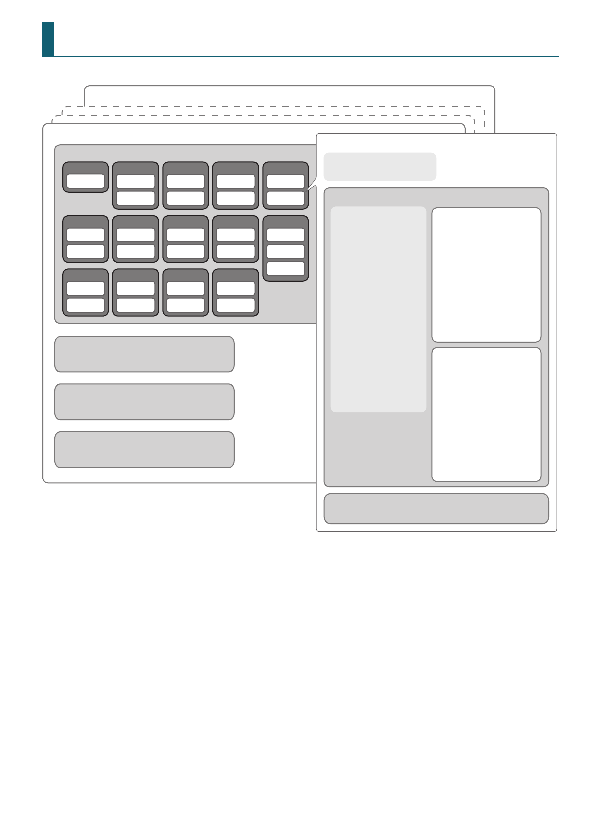
Drum Kit Parameter Structure
Drum kit 100
Drum kit 1
Pads
KICK *1
Head
TOM 4
Head
Rim
AUX 1
Head
Rim
[AMBIENCE] (p. 11)
ROOM, REVERB, STEREO ENHANCER
[MIXER] (p. 3)
MULTI-EFFECT, MASTER COMP, MASTER EQ,
PEDAL HH VOLUME, XSTICK VOLUME
[KIT] (MENU) (p. 3)
KIT NAME, KIT VOLUME, COLOR, FAVORITE,
BRUSH SWITCH, KIT TEMPO SWITCH/TEMPO
SNARE
Head
Rim
HI-HAT
Head
Rim
AUX 2
Head
Rim
TOM 1
Head
Rim
CRASH 1
Head
Rim
AUX 3
Head
Rim
TOM 2
Head
Rim
CRASH 2
Head
Rim
AUX 4
Head
Rim
TOM 3
Head
Rim
RIDE *2
Head
Rim
Bell
Pad settings
[MIXER] (p. 13)
PAD COMP, MFX DRY + WET
Head
[INSTRUMENT] (p. 6)
5 SUB INST ON/OFF
5 SUB INST LAYER TYPE
5 SUB INST FADE POINT
[AMBIENCE] (p. 11)
5 ROOM SEND VOLUME
5 REVERB SEND VOLUME
[MIXER] (p. 13)
5 PAN
5 MINIMUM/MAXIMUM
VOLUME
5 PAD EQ
5 MFX ASSIGN,
SEND VOLUME
[KIT] (MENU) (p. 3)
5 PEDAL BEND/POSITION/
POSITION AREA/MUTE
GROUP
5 MIDI NOTE/GATE/
CHANNEL
Instrument (main)
[INSTRUMENT] (p. 6)
5 INST NUMBER
5 V-EDIT PARAMETER
5 MIC POSITION/
ELEMENT LEVEL/WIDTH
5 TRANSIENT
[AMBIENCE] (p. 11)
5 STEREO ENHANCER SEND
VOLUME
[MIXER] (p. 13)
5 MAIN INST VOLUME
Sub-instrument
[INSTRUMENT] (p. 6)
5 INST NUMBER
5 V-EDIT PARAMETER
5 MIC POSITION/
ELEMENT LEVEL/WIDTH
5 TRANSIENT
5 SUB VOLUME
[AMBIENCE] (p. 11)
5 STEREO ENHANCER SEND
VOLUME
[MIXER] (p. 13)
5 (NONE)
*1 KICK does not have a rim.
*2 For RIDE, the bell can be set in the same way as the head.
Rim
Same as the head
47
Page 48
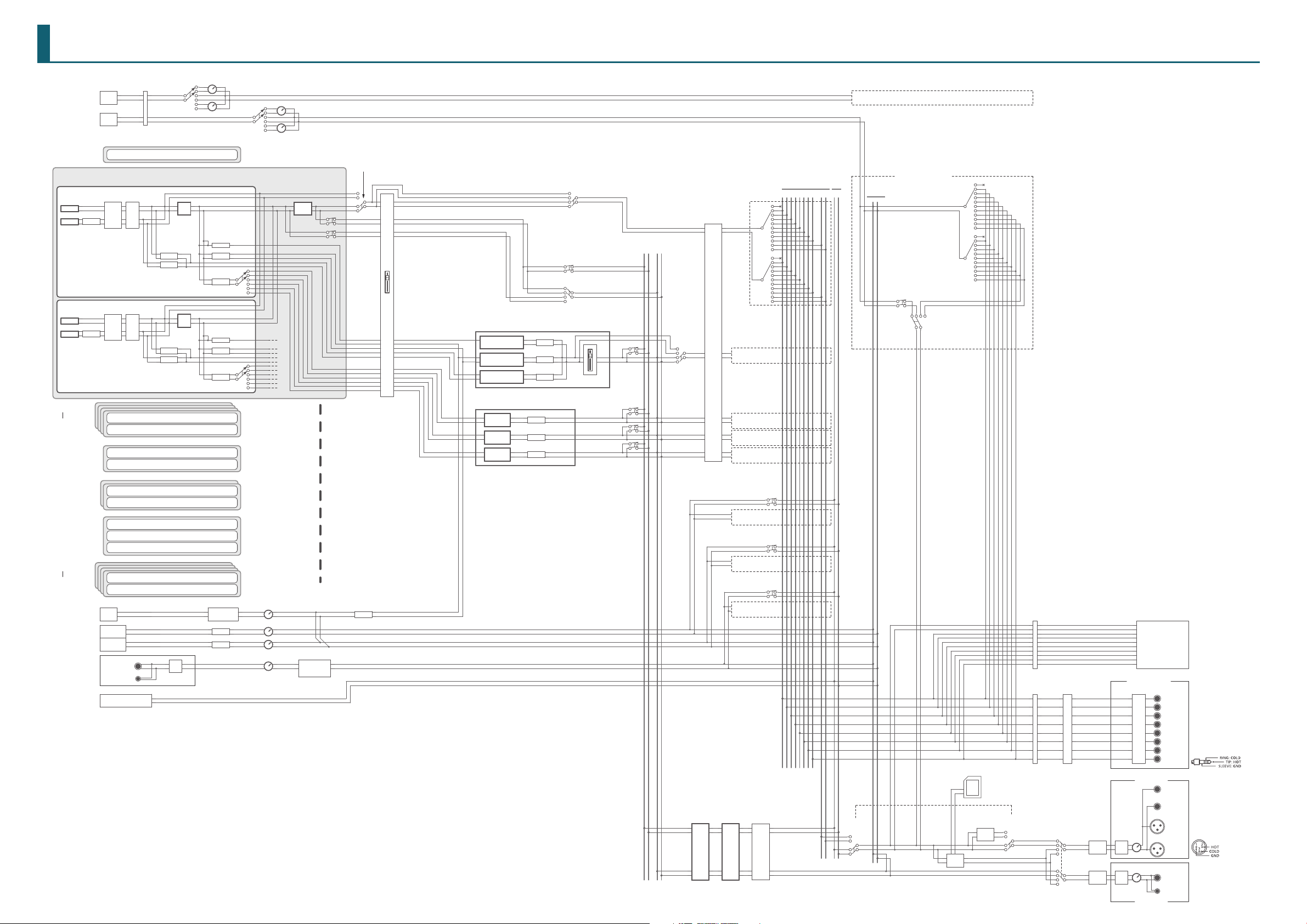
USB Audio
I
PHONES
C
MIX IN
1 KICK
(Fader KICK)
SONG
7 HI-HAT
(Fader HI-HAT)
8 CRASH1,
9 CRASH2
(Fader CRASH)
SETUP/USB AUDIO/
3 TOM1
6 TOM4
(Fader TOMS)
11 AUX1
14 AUX4
(Fader AUX)
MASTER OUT (BALANCED) jacks
10 RIDE
(Fader RIDE)
Block Diagram
Volume Select/
Input MAIN
NPUT
INPUT
MAIN
INPUT
SUB
SETUP/USB AUDIO/
Input Gain
[SONG]
[CLICK]
SETUP/USB AUDIO/
Volume Select/
Input SUB
[SONG]
[CLICK]
(USB AUDIO INPUT ROUTING)
2 SNARE
(Fader SNARE)
HEAD
MAIN INST
SUB INST
INSTRUMENT/
Sub Volume
RIM
MAIN INST
SUB INST
INSTRUMENT/
Sub Volume
LICK
HEAD
MIXER
VOLUME
MIXER
VOLUME
HEAD
RIM
HEAD
RIM
HEAD
RIM
HEAD
RIM
BELL
HEAD
RIM
CLICK
SOUND
SONG (AUDIO)
INTERNAL/SD
SONG CLICK
TRACK
Rear
(Stereo, 1/4 TRS)
Front
(Stereo, Mini)
USER SAMPLE PREVIEW
(from SD/Internal)
MIXER
PAN
MIXER
PAN
PAD
EQ
Amb Stereo Enhancer
Main Send
Amb Stereo Enhancer
Sub Send
PAD
EQ
Amb Stereo Enhancer
Main Send
Amb Stereo Enhancer
Sub Send
A/D
Amb Room Send
Amb Reverb Send
MFX Send
MFX
ASSIGN
Amb Room Send
Amb Reverb Send
MFX Send
MFX
ASSIGN
CLICK SETTING
Pan, Level
SONG/Song Level
SONG/Song Click Track Level
[CLICK]
[SONG]
[CLICK]
[MIX IN]
PAD
COMP
MFX WET+DRY
MIX IN SETTING
Input, Mode, Gain
SETUP/OUTPUT ROUTING/
PadEq/Comp to Direct
OFF
ON
CLICK/Amb (Reverb) Send
[FADER]
AMBIENCE
ROOM
REVERB
STEREO
ENHANCER
MULTI EFFECT(MFX)
MFX1
MFX2
MFX3
ROOM LEVEL
REVERB LEVEL
STEREO ENHANCER
LEVEL
MFX1 LEVEL
MFX2 LEVEL
MFX3 LEVEL
SETUP/OUTPUT/OUTPUT ROUTING/
OFF
Fader to Direct
ON
SETUP/OUTPUT/
PAD OUTPUT ASSIGN MASTER
ON
SETUP/OUTPUT/OUTPUT ROUTING/
OFF
PadComp to Phones
[FADER]
(AMBIENCE)
SETUP/OUTPUT/
OTHER OUTPUT
ASSIGN MASTER
SETUP/OUTPUT/
OTHER OUTPUT
ASSIGN MASTER
(Drum Mix
for MASTER)
(Drum Mix
for PHONES)
OFF
ON
SETUP/OUTPUT/
OUTPUT ROUTING/
Fader to Direct
MASTER
COMP
KIT
Volume
SETUP/OUTPUT/
PAD OUTPUT
ASSIGN DIRECT
SETUP/OUTPUT/
OTHER OUTPUT
ASSIGN DIRECT
SETUP/OUTPUT/
OTHER OUTPUT
ASSIGN DIRECT
SETUP/OUTPUT/
OTHER OUTPUT
ASSIGN DIRECT
SETUP/OUTPUT/
OTHER OUTPUT
ASSIGN DIRECT
SETUP/OUTPUT/
OTHER OUTPUT
ASSIGN DIRECT
SETUP/OUTPUT/
OTHER OUTPUT
ASSIGN DIRECT
SETUP/OUTPUT/
OTHER OUTPUT
ASSIGN DIRECT
MASTEREQKIT
SETUP/OUTPUT/
OTHER OUTPUT
ASSIGN MASTER
SETUP/OUTPUT/
OTHER OUTPUT
ASSIGN MASTER
SETUP/OUTPUT/
OTHER OUTPUT
ASSIGN MASTER
Volume
MASTER
(NORMAL)
DIRECT
MASTER
87654321
RL
MASTER DIRECT
DiRDiL
MASTER NORMAL
SETUP/OUTPUT/
OUTPUT ROUTING/
Master Out
DIRECT
NORMAL
OFF
1
2
3
4
5
6
7
8
DiL
DiR
OFF
1
2
3
4
5
6
7
8
DiL
DiR
DIRECT 1–8
(USB AUDIO INPUT ROUTING)
PHONES
L R
SETUP/OUTPUT/
OTHER OUTPUT ASSIGN MASTER
SETUP/OUTPUT/
OUTPUT ROUTING/
Master Out
SETUP/OUTPUT/
OTHER OUTPUT
ASSIGN DIRECT
DIRECTNORMAL
SONG
EXPORT
Gain
OFF
1
2
3
4
5
6
7
8
DiL
DiR
OFF
1
2
3
4
5
6
7
8
DiL
DiR
SD
SONG EXPORT
Card
(Audio, SMF)
SETUP/OUTPUT/
OUTPUT ROUTING/
Direct Out Att
SETUP/USB AUDIO/
Output Gain
SETUP/OUTPUT/
OUTPUT ROUTING/
Direct Out Att
SETUP/OUTPUT/
OUTPUT ROUTING/
Master Out
DIRECT
NORMAL
SETUP/OUTPUT/
OUTPUT ROUTING/
Lo Cut DirectOut
(Sw)
(SONG Export Preview)
SETUP/OUTPUT/
OUTPUT
ROUTING/
Lo Cut MaterOut
(Sw)
(Sw)
SETUP/OUTPUT/
OUTPUT ROUTING/
Lo Cut PhonesOut
(MASTER L)
(MASTER R)
(IN 1)
(IN 2)
(IN 3)
(IN 4)
(IN 5)
(IN 6)
(IN 7)
(IN 8)
DIRECT OUT
DA CONVERTER
D/A
[MASTER]
D/A
[PHONES]
MASTER
USB Audio
Output
DIRECT 1/L
(BALANCED)
DIRECT 2/R
(BALANCED)
DIRECT 3/L
(BALANCED)
DIRECT 4/R
(BALANCED)
DIRECT 5/L
(BALANCED)
DIRECT 6/R
(BALANCED)
DIRECT 7/L
(BALANCED)
DIRECT 8/R
(BALANCED)
L/MONO
(UNBALANCED)
R
(UNBALANCED)
L
(BALANCED)
R
(BALANCED)
1/4 TRS
MINI
Pin assignment of the
DIRECT OUT (BALANCED) jacks
Pin assignment of the
02
 Loading...