

Page 1
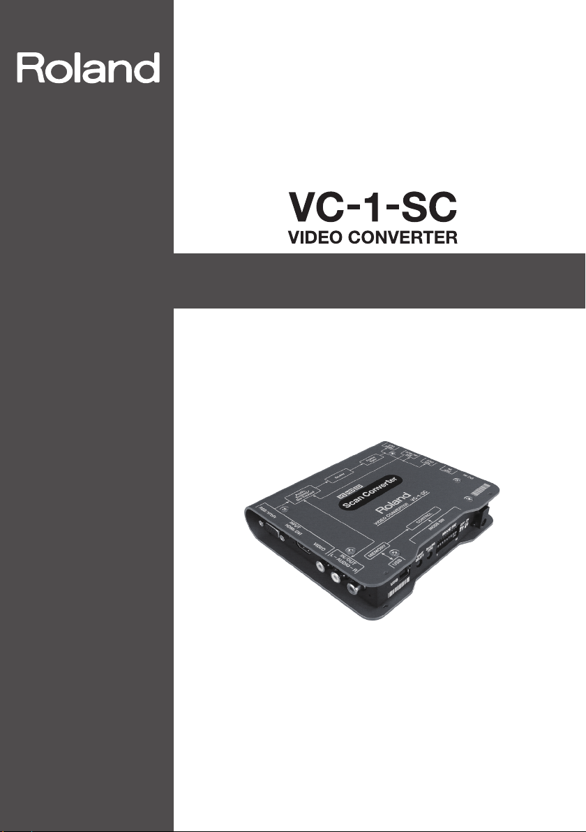
Owner’s Manual
Before using this unit, carefully read the sections entitled “USING THE UNIT
SAFELY” (p. 3) and “IMPORTANT NOTES” (p. 6). These sections provide important
information concerning the proper operation of the unit. Additionally, in
order to feel assured that you have gained a good grasp of every feature of
your new unit, read Owner’s Manual in its entirety. This manual should be
saved and kept on hand as a convenient reference.
Scan Converter
Copyright © 2013 ROLAND CORPORATION
All rights reserved. No part of this publication may be reproduced in any form without the
written permission of ROLAND CORPORATION.
Page 2

IMPORTANT: THE WIRES IN THIS MAINS LEAD ARE COLOURED IN ACCORDANCE WITH THE FOLLOWING CODE.
NEUTRAL
BLUE:
LIVE
BROWN:
As the colours of the wires in the mains lead of this apparatus may not correspond with the coloured markings identifying
the terminals in your plug, proceed as follows:
The wire which is coloured BLUE must be connected to the terminal which is marked with the letter N or coloured BLACK.
The wire which is coloured BROWN must be connected to the terminal which is marked with the letter L or coloured RED.
Under no circumstances must either of the above wires be connected to the earth terminal of a three pin plug.
For the U.K.
2
Page 3
USING THE UNIT SAFELY
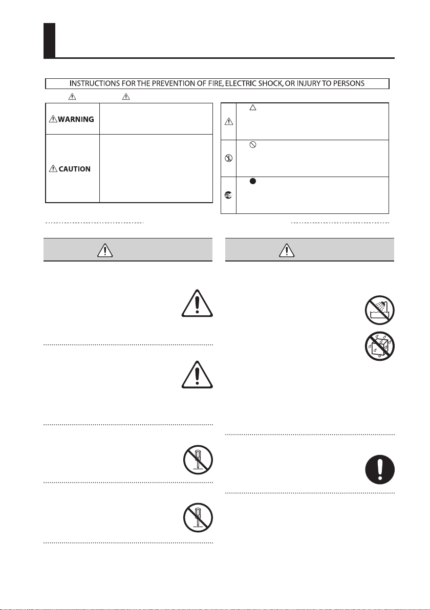
About WARNING and CAUTION Notices
Used for instructions intended to alert the
user to the risk of death or severe injury
should the unit be used improperly.
Used for instructions intended to alert the
user to the risk of injury or material
damage should the unit be used
improperly.
* Material damage refers to damage or
other adverse eects caused with
respect to the home and all its
furnishings, as well to domestic animals
or pets.
ALWAYS OBSERVE THE FOLLOWING
WARNING WARNING
To completely turn o power to the unit, pull out
the plug from the outlet
When the power needs to be completely
turned o, pull out the plug from the
outlet. For this reason, the outlet into
which you choose to connect the power
cord’s plug should be one that is within
easy reach and readily accessible.
Concerning the Auto O function
The power to this unit will be turned o
automatically after a predetermined
amount of time has passed since the last
input of signal (AUTO OFF function). If
you do not want the power to be turned
o automatically, disengage the Auto O function
(p. 12).
Do not disassemble or modify by yourself
Do not carry out anything unless you are
instructed to do so in the owner’s manual.
Otherwise, you risk causing malfunction.
Do not repair or replace parts by yourself
Refer all servicing to your retailer, the
nearest Roland Service Center, or an
authorized Roland distributor, as listed on
the “Information.”
About the Symbols
The symbol alerts the user to important instructions or
warnings. The specic meaning of the symbol is
determined by the design contained within the triangle. In
the case of the symbol at left, it is used for general
cautions, warnings, or alerts to danger.
The symbol alerts the user to items that must never be
carried out (are forbidden). The specic thing that must
not be done is indicated by the design contained within
the circle. In the case of the symbol at left, it means that
the unit must never be disassembled.
The symbol alerts the user to things that must be
carried out. The specic thing that must be done is
indicated by the design contained within the circle. In the
case of the symbol at left, it means that the power-cord
plug must be unplugged from the outlet.
Do not use or store in the following types of
locations
• Subject to temperature extremes
(e.g., direct sunlight in an enclosed
vehicle, near a heating duct, on top
of heat-generating equipment);
or are
• Damp (e.g., baths, washrooms, on
wet oors); or are
• Exposed to steam or smoke; or are
• Subject to salt exposure; or are
• Exposed to rain; or are
• Dusty or sandy; or are
• Subject to high levels of vibration and
shakiness.
Do not place in an unstable location
Otherwise, you risk injury as the result of
the unit toppling over or dropping down.
3
Page 4
USING THE UNIT SAFELY
WARNING WARNING
Use only the supplied AC adaptor and the correct
voltage
Be sure to use only the AC adaptor
supplied with the unit. Also, make sure
the line voltage at the installation
matches the input voltage specied on
the AC adaptor’s body. Other AC adaptors
may use a dierent polarity, or be designed for a
dierent voltage, so their use could result in
damage, malfunction, or electric shock.
Use only the supplied power cord
Use only the attached power cord. Also,
the supplied power cord must not be
used with any other device.
Do not bend the power cord or place heav y
objects on it
Otherwise, re or electric shock may
result.
Avoid extended use at high volume
Use of the unit at high volume for
extended periods of time may cause
hearing loss. If you ever experience any
hearing loss or ringing in the ears, you
should immediately stop using the unit
and consult a specialized physician.
Do not allow foreign objects or liquids to enter
unit; never place containers with liquid on unit
Do not place containers containing liquid
(e.g., ower vases) on this product. Never
allow foreign objects (e.
objects, coins, wires) or liquids (e.g., water
or juice) to enter this product. Doing so
may cause short circuits, faulty operation,
or other malfunctions.
g., ammable
Turn o the unit if an abnormality or
malfunc tion occurs
Immediately remove the AC adaptor from
the outlet, and request servicing by your
retailer, the nearest Roland Service
Center, or an authorized Roland
distributor, as listed on the “Information”
when:
• The AC adaptor or the power cord has been
damaged; or
• If smoke or unusual odor occurs; or
• Objects have fallen into, or liquid has been
spilled onto the unit; or
• The unit has been exposed to rain (or otherwise
has become wet); or
• The unit does not appear to operate normally or
exhibits a marked change in performance.
Be cautious to protect children from injury
Always make sure that an adult is on
hand to provide supervision and
guidance when using the unit in places
where children are present, or when a
child will be using the unit.
Do not drop or subject to strong impact
Otherwise, you risk causing damage or
malfunction.
Do not share an outlet with an unreasonable
number of other devices
Otherwise, you risk overheating or re.
Do not use overseas
Before using the unit in overseas, consult
with your retailer, the nearest Roland
Service Center, or an authorized Roland
distributor, as listed on the “Information.”
4
Page 5

USING THE UNIT SAFELY
CAUTION
Place in a well ventilated location
The unit and the AC adaptor should be
located so their location or position does
not interfere with their proper
ventilation.
When disconnecting the power cord, grasp it by
the plug
To prevent conductor damage, always
grasp the power cord by its plug when
disconnecting it from this unit or from a
power outlet.
Periodically clean the power plug
An accumulation of dust or foreign
objects between the power plug and the
power outlet can lead to re or electric
shock.
At regular intervals, be sure to pull out the
power plug, and using a dry cloth, wipe away any
dust or foreign objects that may have accumulated.
Disconnect the power plug whenever the unit
will not be used for an extended period of time
Fire may result in the unlikely event that a
breakdown occurs.
Route all power cords and cables in such a way as
to prevent them from getting entangled
Injury could result if someone were to
trip on a cable and cause the unit to fall
or topple.
Avoid climbing on top of the unit, or placing
heavy objects on it
Otherwise, you risk injury as the result of
the unit toppling over or dropping down.
CAUTION
Disconnect all cords/cables before moving the
unit
Before moving the unit, disconnect the
power plug from the outlet, and pull out
all cords from external devices.
Before cleaning the unit, disconnect the power
plug from the outlet
If the power plug is not removed from the
outlet, you risk receiving an electric
shock.
Whenever there is a threat of lightning,
disconnect the power plug from the outlet
If the power plug is not removed from the
outlet, you risk receiving an electric
shock.
Keep small items out of the reach of children
To prevent accidental ingestion of the
parts listed below, always keep them out
of the reach of small children.
• Included Parts
Rubber feet (p. 8)
Handle the ground terminal carefully
If you remove the screw from the ground
terminal, be sure to replace it; don’t leave
it lying around where it could accidently
be swallowed by small children. When
refastening the screw, make that it is
rmly fastened, so it won’t come loose.
Take care not to get burned
This unit may become hot, so take care to
avoid burns.
Never connect/disconnec t a power plug if your
hands are wet
Otherwise, you could receive an electric
shock.
5
Page 6

IMPORTANT NOTES
Power Supply
• Do not connect this unit to same electrical outlet
that is being used by an electrical appliance that
is controlled by an inver ter or a motor (such as a
refrigerator, washing machine, microwave oven, or
air conditioner). Depending on the way in which
the electrical appliance is used, power supply noise
may cause this unit to malfunction or may produce
audible noise. If it is not practical to use a separate
electrical outlet, connect a power supply noise
lter between this unit and the electrical outlet.
• The AC adaptor will begin to generate heat after
long hours of consecutive use. This is normal, and
is not a cause for concern.
Placement
• Using the unit near power ampliers (or other
equipment containing large power transformers)
may induce hum. To alleviate the problem, change
the orientation of this unit; or move it farther away
from the source of interference.
• This unit may interfere with radio and television
reception. Do not use this unit in the vicinity of
such receivers.
• Noise may be produced if wireless communications
devices, such as cell phones, are operated in the
vicinity of this unit. Such noise could occur when
receiving
or initiating a call, or while conversing.
Should you experience such problems, you should
relocate such wireless devices so they are at a
greater distance from this unit, or switch them o.
• When moved from one location to another where
the temperature and/or humidity is very dierent,
water droplets (condensation) may form inside
the unit. Damage or malfunction may result if you
attempt to use the unit in this condition. Therefore,
before using the unit, you must allow it to stand
for several hours, until the condensation has
completely evaporated.
• Depending on the material and temperature of the
surface on which you place the unit, its rubber feet
may discolor or mar the surface.
You can place a piece of felt or cloth under the
rubber feet to prevent this from happening. If you
do so, please make sure that the unit will not slip or
move accidentally.
• Do not place containers or anything else
containing liquid on top of this unit. Also,
whenever any liquid has been spilled on the
surface of this unit, be sure to promptly wipe it
away using a soft, dr y cloth.
Maintenance
• For everyday cleaning wipe the unit with a soft,
dry cloth or one that has been slightly dampened
with water. To remove stubborn dirt, use a cloth
impregnated with a mild, non-abrasive detergent.
Afterwards, be sure to wipe the unit thoroughly
with a soft, dry cloth.
• Never use benzine, thinners, alcohol or solvents of
any kind, to avoid the possibility of discoloration
and/or deformation.
Repairs and Data
• Before sending the unit away for repairs, be sure to
make a backup of the data stored within it; or you
may prefer to write down the needed information.
Although we will do our utmost to preserve the
data stored in your unit when we carry out repairs,
in some cases, such as when the memory section
is physically damaged, restoration of the stored
content may be impossible. Roland assumes no
liability concerning the restoration of any stored
content that has been lost.
Additional Precautions
• Any data stored within the unit can be lost as the
result of equipment failure, incorrect operation,
etc. To protect yourself against the irretrievable
loss of data, try to make a habit of creating regular
backups of the data you’ve stored in the unit.
• Roland assumes no liability
restoration of any stored content that has been
lost.
• Use a reasonable amount of care when using
the unit’s switches, jacks and connec tors. Rough
handling can lead to malfunctions.
• When disconnecting all cables, grasp the
connector itself—never pull on the cable. This way
you will avoid causing shorts, or damage to the
cable’s internal elements.
• To avoid disturbing others nearby, try to keep the
unit’s volume at reasonable levels.
concerning the
6
Page 7

IMPORTANT NOTES
• When you need to transport the unit, pack it
in shock-absorbent material. Transporting the
unit without doing so can cause it to become
scratched or damaged, and could lead to
malfunction.
About Intellectual Property Rights
• It is forbidden by law to make an audio recording,
video recording, copy or revision of a third party's
copyrighted work (musical work, video work,
broadcast, live performance, or other work),
whether in whole or in part, and distribute,
sell, lease, perform, or broadcast it without the
permission of the copyright owner.
• Do not use this product for purposes that could
infringe on a copyright held by a third party. We
assume no responsibility whatsoever with regard
to any infringements of third-party copyrights
arising through your use of this product.
• MMP (Moore Microprocessor Portfolio) refers to a
patent portfolio concerned with microprocessor
architecture, which was developed by Technology
Properties Limited ( TPL). Roland has licensed this
technology from the TPL Group.
• Roland is an either registered trademark or
trademark of Roland Corporation in the United
States and/or other countries.
• Company names and product names appearing
in this document are registered trademarks or
trademarks of their respective owners.
7
Page 8
Check the Included Items
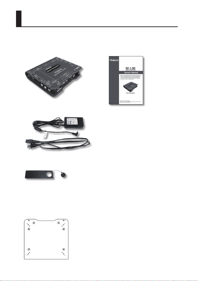
The following items are included. Please make sure that all items are present. If anything is
missing, please contact your dealer.
VC-1-SC itself
AC adaptor and power cord
Rubber feet
* The rubber feet are arranged onto one
pad. Remove each one from the pad if you
wish to install them.
* Attach the included rubber feet to the
locations of bottom panel below as
needed.
Owner’s Manual
8
Page 9

Contents
USING THE UNIT SAFELY .................................................................................................3
IMPORTANT NOTES
Check the Included Items
About the Power Supply
Connecting the AC Adaptor .................................................................................. 10
About Securing the Power Cord ........................................................................11
Turning the Power On and O ............................................................................12
About AUTO OFF ........................................................................................................... 12
Panel Descriptions
Front Panel .........................................................................................................................13
Rear Panel ........................................................................................................................... 14
Side Panel ...........................................................................................................................15
Indicator Colors/Operation ....................................................................16
About Input/Output Formats
Input Formats ..................................................................................................................18
Output Formats .............................................................................................................. 20
Connecting External Equipment
Connecting Source Equipment ..........................................................................21
...............................................................................................................6
.............................................................................................8
............................................................................................10
............................................................................................................. 13
..............................................................................18
.....................................................................21
Connecting Output Equipment .........................................................................23
Connecting a Computer for Remote Control ............................................24
Setting the Operation Mode
Appendices
Main Specications ......................................................................................................27
Dimensions ........................................................................................................................29
Troubleshooting ............................................................................................................ 30
.................................................................................................................................27
................................................................................. 25
9
Page 10
About the Power Supply
Connecting the AC Adaptor
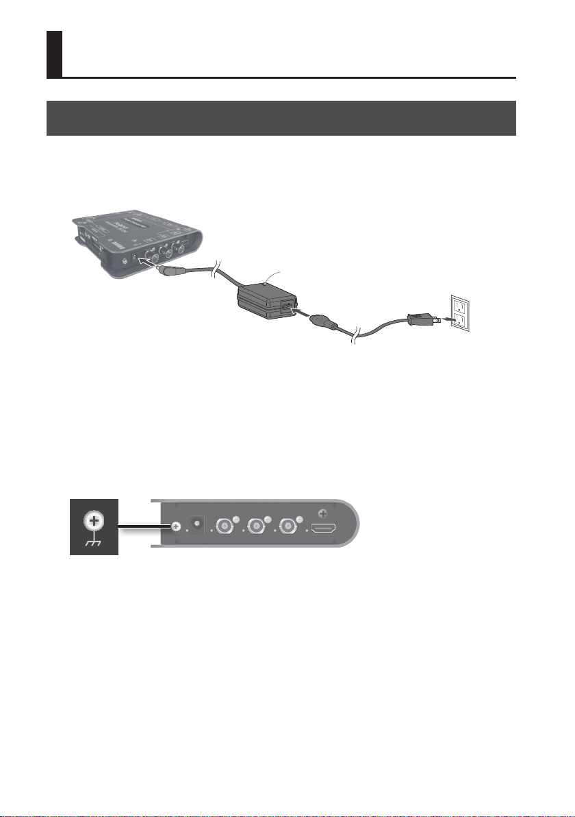
Connect the AC Adaptor as shown in the gure below.
Place the AC adaptor so the side with the indicator (see illustration) faces upwards and the side
with textual information faces downwards.
The indicator will light when you plug the AC adaptor into an AC outlet.
Indicator
Ground terminal
Depending on the circumstances of a particular setup, you may experience a discomforting
sensation, or perceive that the surface feels gritty to the touch when you touch this device, or the
metal portions of other objects. This is due to an innitesimal electrical charge, which is absolutely
harmless. However, if you are concerned about this, connect the ground terminal (see gure)
with an external ground. When the unit is grounded, a slight hum may occur, depending on the
particulars of your installation. If you are unsure of the connection method, contact the nearest
Roland Service Center, or an authorized Roland distributor, as listed on the “Information” leaet.
Unsuitable places for connection
• Water pipes (may result in shock or electrocution)
• Gas pipes (may result in re or explosion)
• Telephone-line ground or lightning rod (may be dangerous in the event of lightning)
10
Page 11
About the Power Supply
About Securing the Power Cord
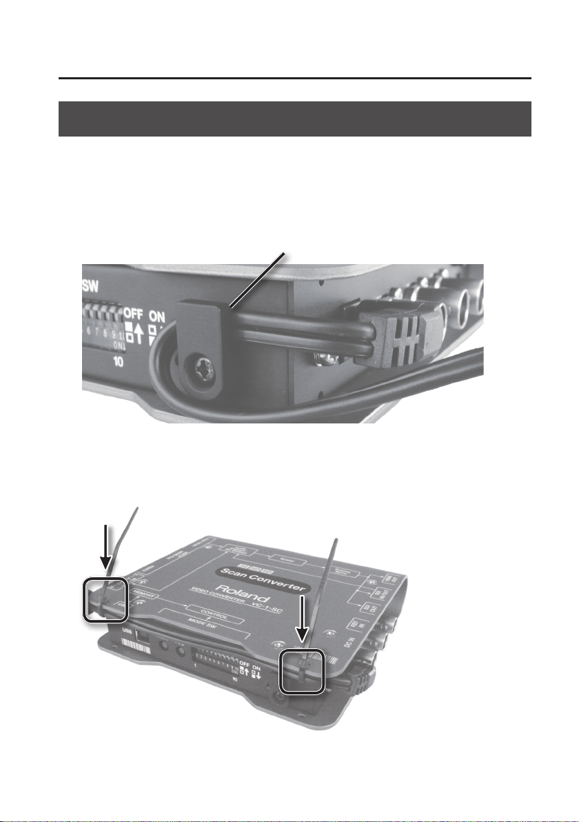
You can use either of the two methods described below to secure the power cord in place. Doing
this can prevent inadvertent disruption of power to your unit (should the plug be pulled out
accidentally) and avoid applying undue stress to the DC IN jack.
Securing using the cord hook
You can secure the cord in place as shown below.
Cord hook
Securing using the holes in the top/bottom panel
You can secure the cord using the holes in the top or bottom panel, as shown below.
11
Page 12

About the Power Supply
Turning the Power On and O
Once everything is properly connected, be sure to follow the procedure below to turn on their
power. If you turn on equipment in the wrong order, you risk causing malfunction or equipment
failure.
* This unit is equipped with a protection circuit. A brief interval (a few seconds) after turning the
unit on is required before it will operate normally.
* Before turning the unit on/o, always be sure to turn the volume down. Even with the volume
turned down, you might hear some sound from the audio output when switching the unit on/
o. However, this is normal and does not indicate a malfunction.
Turning the power on
1. Connect the peripheral devices.
Connect any video cameras and other equipments. To prevent malfunction and equipment
failure, turn o all the units before making any connections.
2. Turn on the power to the VC-1-SC.
Inserting the power cord starts the VC-1-SC.
3. Turn on the power to external equipment.
Turn on the power to the external devices connected to the VC-1-SC.
Turning the power o
1. Turn o the power to external equipment.
Turn o the power to the external devices connected to the VC-1-SC.
2. Turn o the power to the VC-1-SC.
Disconnecting the power cord turns o the power.
About AUTO OFF
The power to this unit will be turned o automatically after a predetermined amount of time
(240 minutes) has passed since the last input of signal or others (AUTO OFF function). AUTO OFF
function activates under following conditions.
• Mode switch (MODE SW) 10 (CONTROL) is set to “ON”
• No USB connection to a computer
• No video input
• No audio input
To turn on the power again, disconnect and reinsert the power cord.
* To disable the AUTO OFF function, set mode switch 10 (CONTROL) to “OFF” (p. 26).
You can also use dedicated remote-control software (VC-1 RCS) to change this setting (p. 24).
12
Page 13
Panel Descriptions
Front Panel
1 2 3 4
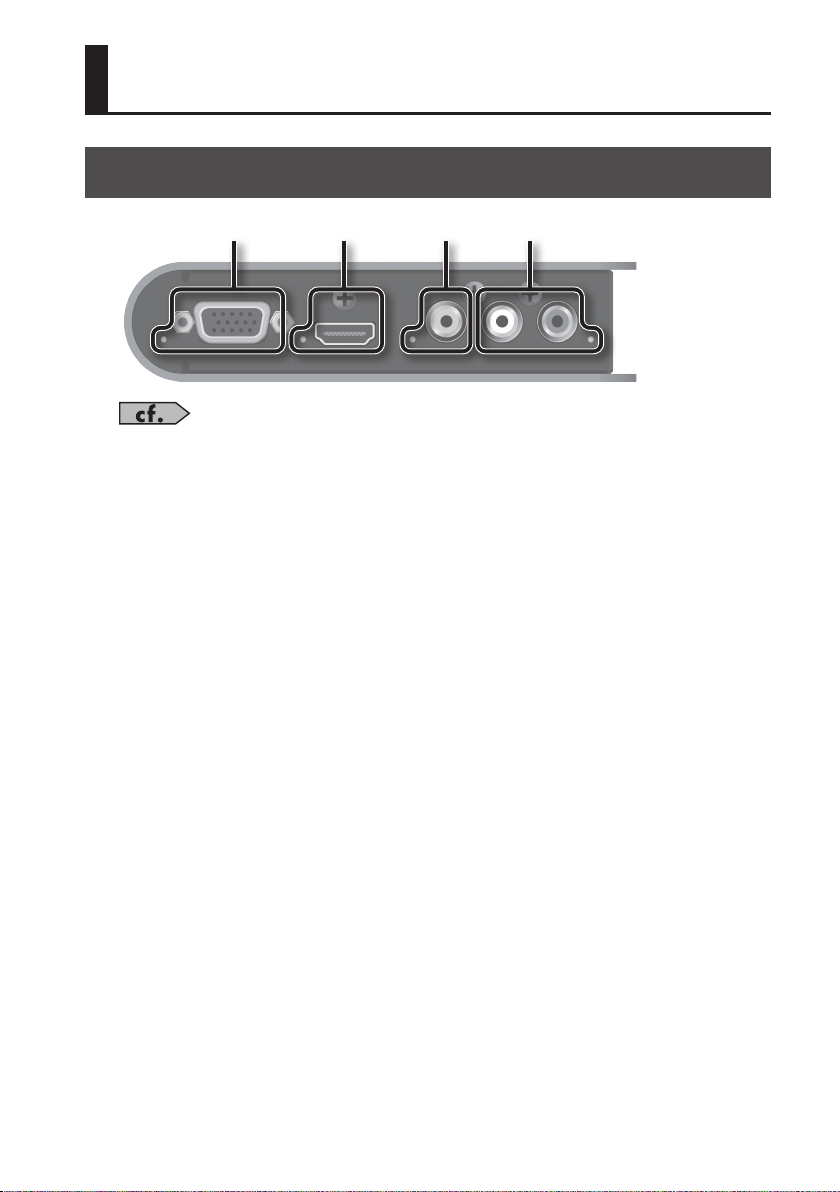
For information on what the colors and the lighted and ashing states of the indicators mean,
refer to “Indicator Colors/Operation” (p. 16).
1. RGB/YPbPr INPUT connector/indicator
Connect RGB signals from a computer, analog-component signals from a video camera, or other
such equipment.
2. HDMI/DVI INPUT connector/indicator
Connect a video camera or other HDMI source equipment.
You can also input DVI-D signals from a computer by using a conversion cable.
3. VIDEO INPUT jack/indicator
Connect composite signals from a video camera or other such equipment.
4. AUDIO IN/OUT jacks/indicator
Connect video-camera audio signals or the like.
You can switch between input (embedding) and output (de-embedding) by operating mode
switch 1 (MODE SW 1; p. 25).
13
Page 14
Panel Descriptions
Rear Panel
1 2 3 4 5
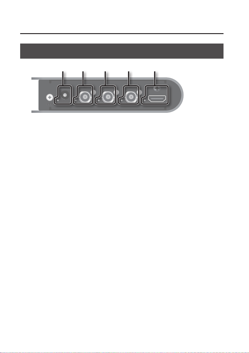
1. DC IN jack/indicator
Connect the included AC Adaptor. The indicator lights up when the VC-1-SC is receiving power.
2. REF IN connector/indicator
Connect a clock source device for synchronization.
* It is possible to use this unit as a frame synchronizer when supported sync signal is input.
3. SDI OUT connector/indicator
Connect a video deck, monitor, or other SDI input equipment.
4. SDI IN/OUT connector/indicator
This functions as input when SDI input has been selected and as output at other times.
When using this for input, connect a video camera or other SDI source equipment.
When using this for output, connect a video deck, monitor, or other SDI input equipment.
5. HDMI OUT connector/indicator
Connect a TV monitor or other HDMI input equipment.
14
Page 15
Panel Descriptions
Side Panel
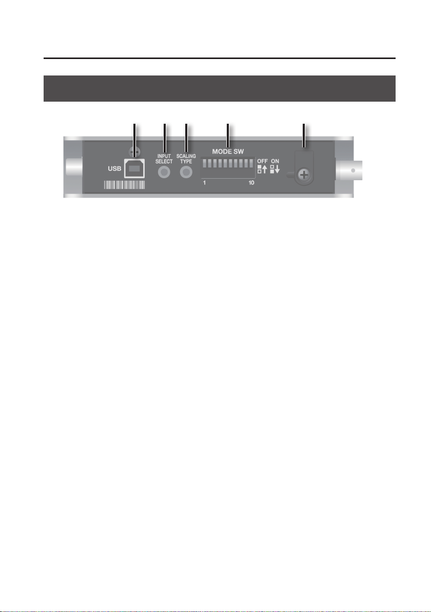
3 4 51 2
1. USB port
Connect a computer used for remote control (p. 24).
* Operating the VC-1-SC by remote control requires downloading of the dedicated software
(VC-1 RCS) and installing it on a computer. You can download the dedicated software from the
following Roland website.
http://www.rolandsystemsgroup.net/
2. INPUT SELECT switch
Each press switches the input connector. Refer to “Setting the Operation Mode” (p. 25).
* If the switch is dicult to press, use the tip of a pen or other narrow object to press it.
3. SCALING TYPE switch
Each press changes the screen aspect (scaling). Refer to “Setting the Operation Mode” (p. 25).
* If the switch is dicult to press, use the tip of a pen or other narrow object to press it.
4. Mode switches (MODE SW)
These set the VC-1-SC’s operation mode. Refer to “Setting the Operation Mode” (p. 25).
* Use the tip of a pen or similar object to change the setting of a switch.
5. Cord hook
Use this to secure the AC Adaptor cord in place. Refer to “About Securing the Power Cord” (p. 11).
15
Page 16
Panel Descriptions
Indicator Colors/Operation
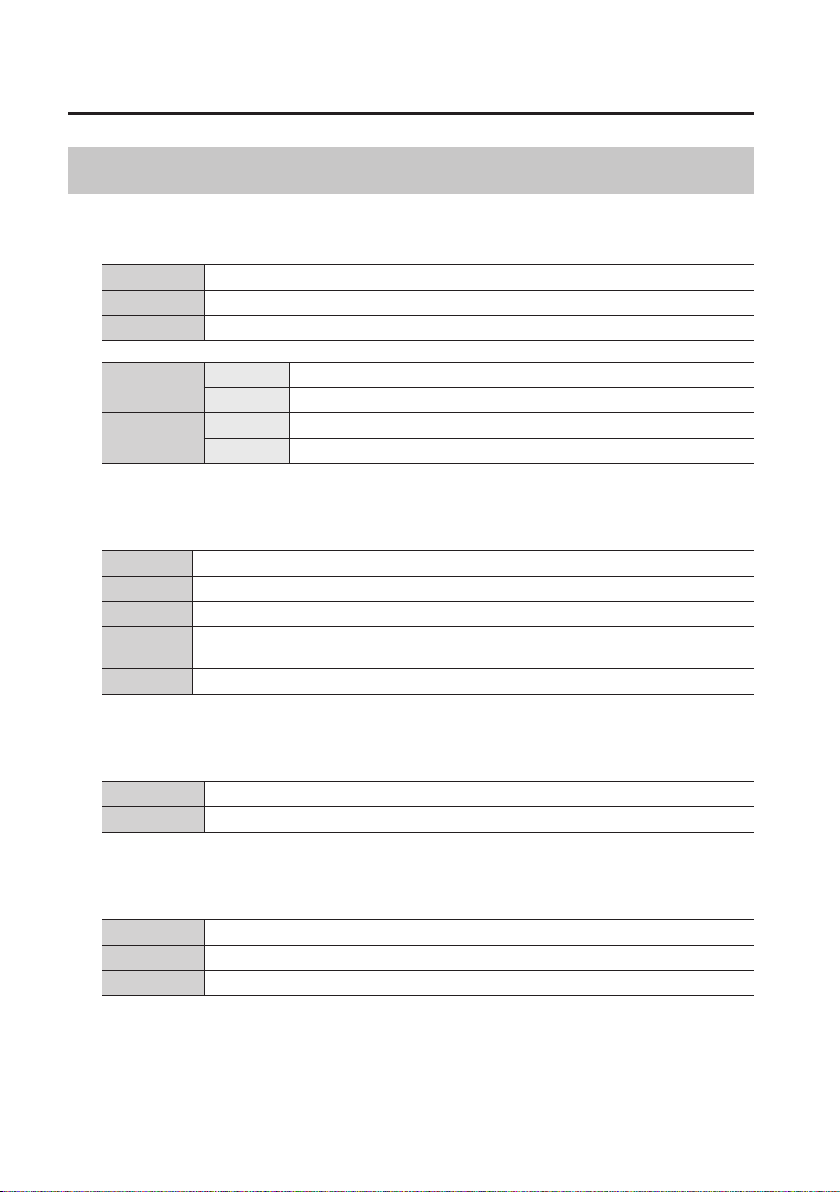
SDI IN/OUT
Red SD-SDI input/output
Orange HD-SDI input/output
Green 3G-SDI input/output
SDI IN
SDI OUT
Lighted Proper input
Flashing Input connector selected (no input)
Lighted Proper output
Flashing Cannot output properly
HDMI IN/OUT
Red RGB input/output
Orange YCC 444 input/output
Green YCC 422 input/output
Flashing
Unlighted Input connector unselected
Cannot input/output properly because of no HDCP support
or input connector selected (no input)
AUDIO IN/OUT
Green/lighted -24 dB input/output
Red/lighted -6 dB input/output
REF IN
Lighted The unit locks to clock from the source device
Flashing Unsupported clock is input
Unlighted No input via REF IN (video input locked or free-run)
16
Page 17
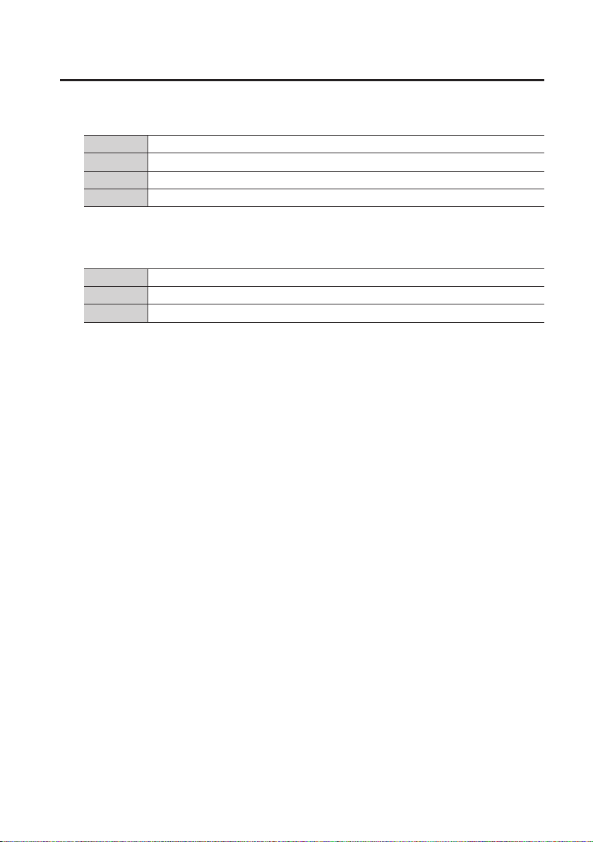
RGB/YPbPr IN
Red RGB input
Green YPbPr input
Lighted Input connector selected (no input)
Unlighted Input connector unselected
VIDEO IN
Lighted Signal input
Flashing Input connector selected (no input)
Unlighted Input connector unselected
Panel Descriptions
17
Page 18
About Input/Output Formats
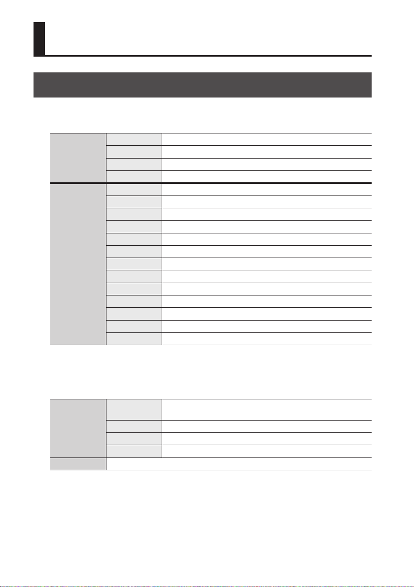
Input Formats
RGB/YPbPr IN connector
1920 x 1080 60p, 59.94p, 50p, 60i, 59.94i, 50i, 24PsF, 23.98PsF
YPbPr
RGB
1280 x 720 60p, 59.94p, 50p
720 x 480 59.94p, 59.94i
720 x 576 50p, 50i
640 x 480 60, 72, 75, 85 Hz
800 x 600 56, 60, 72, 75, 85 Hz
1024 x 768 60, 70, 75, 85 Hz
1280 x 768 60, 75, 85 Hz
1360 x 768 60 Hz
1152 x 864 75 Hz
1400 x 900 60, 75, 85 Hz
1280 x 960 60, 85 Hz
1280 x 1024 60, 75 Hz
1400 x 1050 60, 75 Hz
1680 x 1050 60 Hz
1600 x 1200 60 Hz
1920 x 1200 60 Hz Reduced blanking
* RGB IN compatible only with input compliant with VESA DMT Version 1.0 Revision 11.
SDI IN connector
1920 x 1080
Video
Audio Linear PCM, 24 bits/48 kHz, 16 channels
1280 x 720 60p, 59.94p, 50p, 30p, 29.97p, 25p, 24p, 23.98p
720 x 487 59.94i
720 x 576 50i
18
60p, 59.94p, 50p, 30p, 29.97p, 25p, 24p, 23.98p, 60i, 59.94i, 50i, 24PsF,
23.98PsF
Page 19
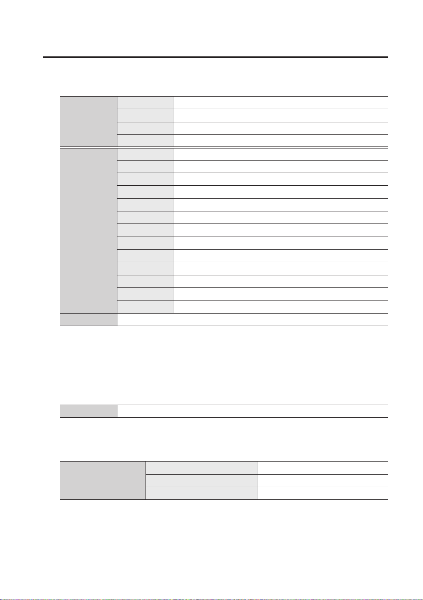
HDMI/DVI IN connector
1920 x 1080 60p, 59.94p, 50p, 30p, 29.97p, 25p, 24p, 23.98p, 60i, 59.94i, 50i
HDMI
DVI
Audio Linear PCM, 24 bits/48 kHz, 8 channels
1280 x 720 60p, 59.94p, 50p, 30p, 29.97p, 25p, 24p, 23.98p
720 x 480 59.94p, 59.94i
720 x 576 50p, 50i
640 x 480 60, 72, 75, 85 Hz
800 x 600 56, 60, 72, 75, 85 Hz
1024 x 768 60, 70, 75, 85 Hz
1280 x 768 60, 75, 85 Hz
1360 x 768 60 Hz
1152 x 864 75 Hz
1400 x 900 60, 75, 85 Hz
1280 x 960 60, 85 Hz
1280 x 1024 60, 75 Hz
1400 x 1050 60, 75 Hz
1680 x 1050 60 Hz
1600 x 1200 60 Hz
1920 x 1200 60 Hz Reduced blanking
About Input/Output Formats
* The VC-1-SC supports HDCP (High-bandwidth Digital Content Protection system). When an
HDCP-applied signal is input, output is possible from only the HDMI OUT connector. Output from
the SDI OUT connector and AUDIO OUT connectors is stopped.
VIDEO IN jack
Video NTSC, PAL
AUDIO IN jacks
Nominal input level -6 dBV
Analog audio
Maximum input level +6 dBV
Input impedance 22 kΩ
19
Page 20
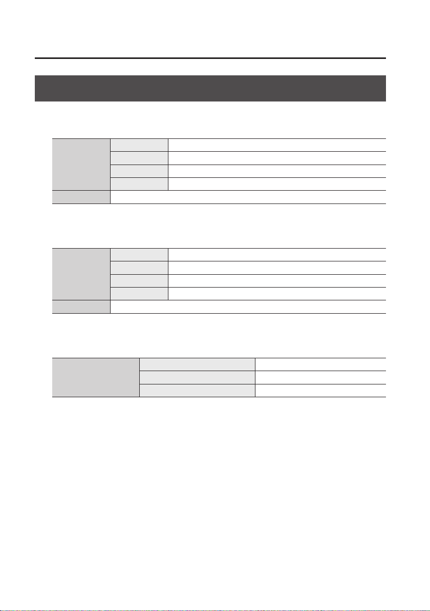
About Input/Output Formats
Output Formats
SDI OUT connectors
1920 x 1080 59.94p, 50p, 59.94i, 50i
Video
Audio Linear PCM, 24 bits/48 kHz, 2 channels
HDMI OUT connector
Video
Audio Linear PCM, 24 bits/48 kHz, 2 channels
AUDIO OUT jacks
1280 x 720 59.94p, 50p
720 x 487 59.94i
720 x 576 50i
1920 x 1080 59.94p, 50p, 59.94i, 50i
1280 x 720 59.94p, 50p
720 x 480 59.94i
720 x 576 50i
20
Analog audio
Nominal output level -6 dBV
Maximum output level +6 dBV
Output impedance 2.2 kΩ
Page 21
Connecting External Equipment
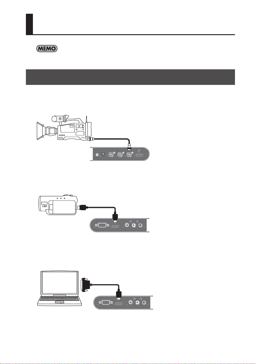
For information on operation modes refer to “Setting the Operation Mode” (p. 25).
Connecting Source Equipment
Connecting SDI equipment
Connect a video camera or other device capable of SDI output to the SDI IN connector.
Connecting HDMI equipment
Connect a video camera or other device capable of HDMI output to the HDMI INPUT connector.
Connecting DVI equipment
Using a conversion cable, connect a computer or other equipment capable of DVI output to the
HDMI/DVI INPUT connector.
21
Page 22
Connecting External Equipment
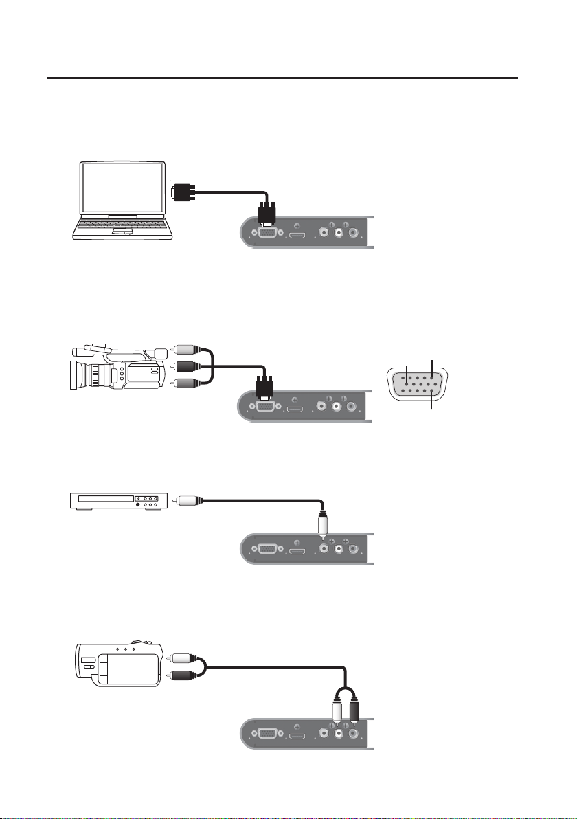
Connecting RGB equipment
Connect a computer or other equipment capable of RGB output to the RGB/YPbPr INPUT
connector.
Connecting component equipment
Using a conversion cable, connect equipment capable of component output to the RGB/YPbPr
INPUT connector.
Female connector
-----------
-----------
----------
15
69
1015
Connecting composite equipment
Connect equipment capable of composite output to the VIDEO INPUT jack.
Connecting audio source equipment
Connect analog audio output from a video camera or other equipment to the AUDIO IN jacks.
Set MODE SW 1 (p. 25) to “OFF” to
switch to AUDIO IN jacks.
1 : Pr
2 : Y
3 : Pb
6 : GND (Pr)
7 : GND (Y)
8 : GND (Pb)
22
Page 23
Connecting External Equipment
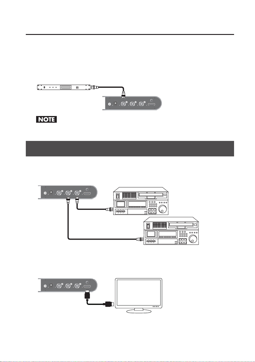
Connecting a clock source
Connect a clock source to the REF IN connector. The VC-1-SC supports the following external
clocks.
• Black burst
• Bi-level/Tri-level synchronization
Never input a signal that includes video. Doing so might cause synchronization to be lost.
Connecting Output Equipment
Connecting SDI equipment
Connect a video deck or other equipment capable of SDI input to the SDI OUT connector.
When the INPUT SELECT switch
(p. 25) is set to Auto, the SDI IN/OUT
connector is locked to operation
as input connector. Use as output
connectors is not possible.
Connecting HDMI equipment
Connect a TV monitor or other equipment capable of HDMI input to the HDMI OUT connector.
23
Page 24
Connecting External Equipment
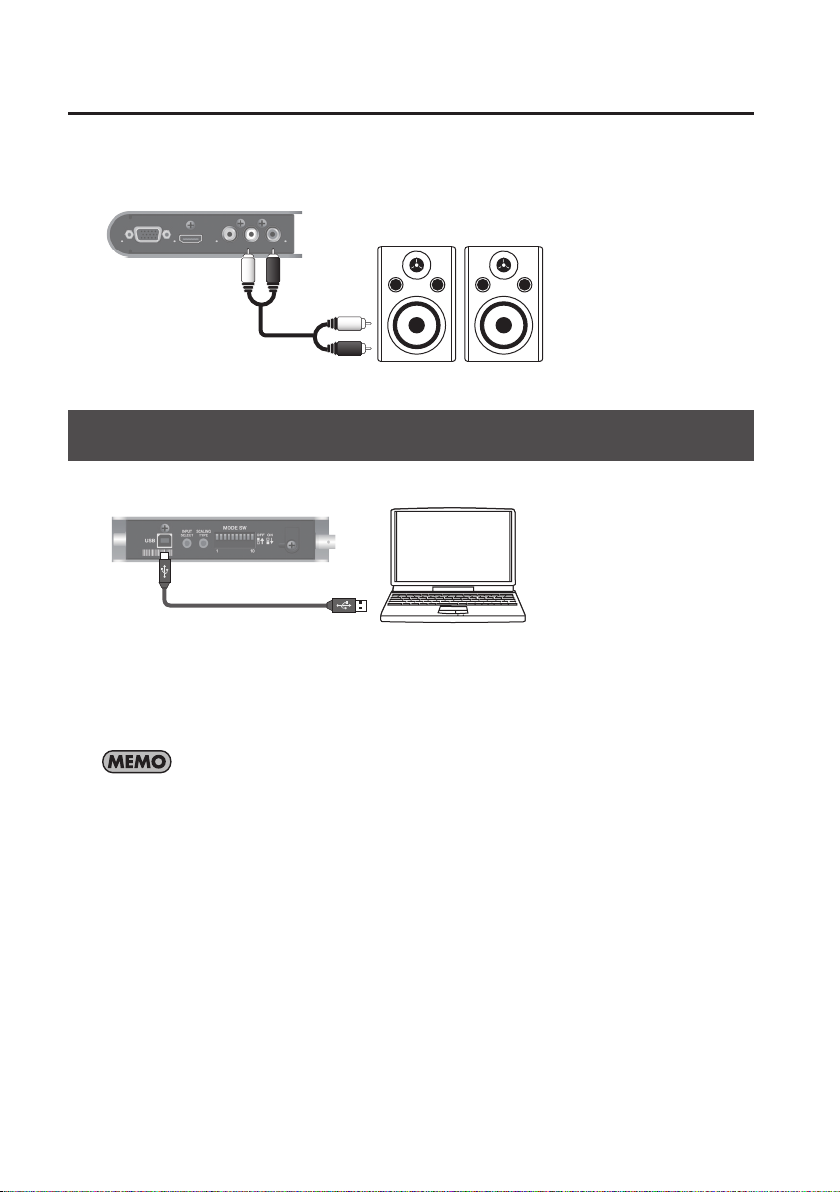
Connecting audio output equipment
Connect powered speakers or the like to the AUDIO OUT jacks.
Set MODE SW 1 (p. 25) to “ON” to
switch to AUDIO OUT jacks.
Connecting a Computer for Remote Control
Connect a computer for remote control to the USB port.
* Operating the VC-1-SC by remote control requires downloading of the dedicated software
(VC-1 RCS) and installing it on a computer. You can download the dedicated software from the
following Roland website.
http://www.rolandsystemsgroup.net/
The VC-1 RCS enables you to make detailed settings that cannot be made using the unit’s mode
switches. The values of the settings are saved to the unit’s internal memory. You can use such
saved settings even when you are using the unit alone, without connecting a computer.
24
Page 25
Setting the Operation Mode
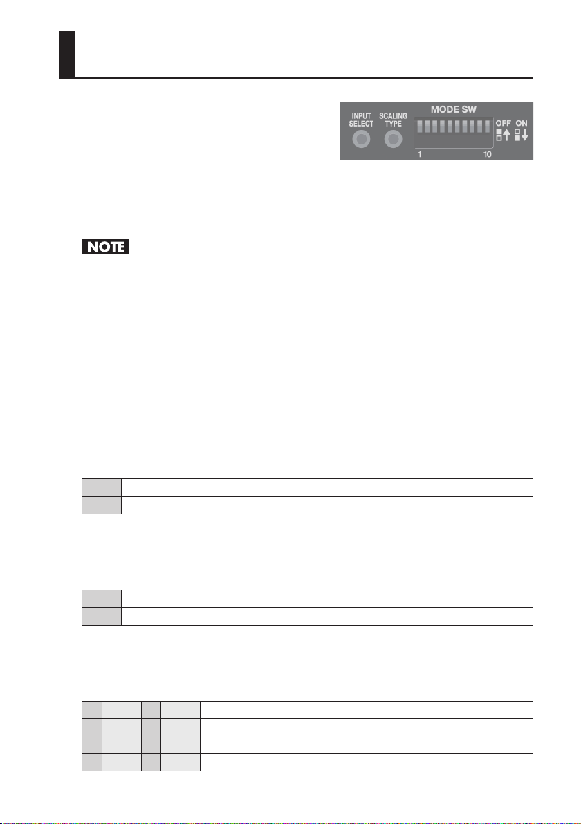
Use the mode switches (MODE SW) on the side panel
to set the operation mode of the VC-1-SC. By default,
only switch 10 is set to “ON.” Before making any
setting changes, rst set switch 10 to “OFF.”
INPUT SELECT switch
Each press switches the input connector as shown below.
Auto g SDI IN g HDMI/DVI IN g RGB/YPbPr IN g VIDEO IN g Auto g
* The indicator for the currently selected connector ashes or lights up steadily.
When the Auto setting has been made, the SDI IN/OUT connector is locked to operation as input
connector. Use as output connector is not possible. Also, when the Auto setting is in eect, never
make simultaneous connections to multiple input connectors.
SCALING TYPE switch
Each press changes the screen aspect (scaling) as shown below.
Full (full-screen output, regardless of dierences in input and output aspect)
g Letterbox (black borders inserted according to dierences in input and output aspect)
g Cropped (parts of the screen cut o according to dierences in input and output aspect)
g Dot by dot (output as-is, with no scaling performed)
g Full g
MODE SW 1
This species audio input and output (embedding/de-embedding).
OFF Audio jacks are used for input (embedding).
ON Audio jacks are used for output (de-embedding).
MODE SW 2
This species the groups for embedding/de-embedding the SDI audio.
OFF 8 channels of Group 1 and Group 2
ON 8 channels of Group 3 and Group 4
MODE SW 3/4
These specify the channels for embedding/de-embedding the audio.
3 OFF 4 OFF Channels 1 and 2
3 ON 4 OFF Channels 3 and 4
3 OFF 4 ON Channels 5 and 6
3 ON 4 ON Channels 7 and 8
25
Page 26
Setting the Operation Mode
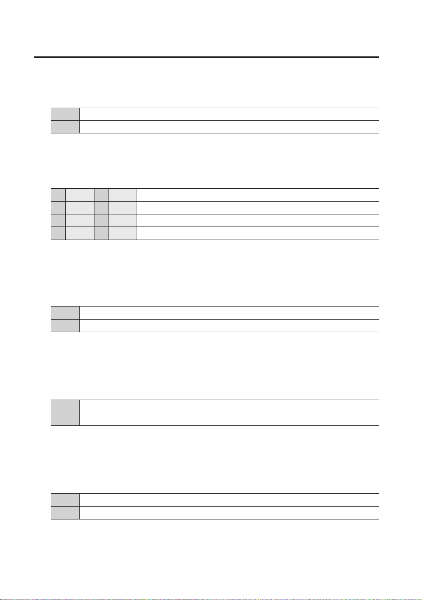
MODE SW 5
This species the frame rate of output.
OFF 59.94 Hz
ON 50 Hz
MODE SW 6/7
This species the output resolution.
6 OFF 7 OFF Output at SD resolution
6 ON 7 OFF Output at 1280 x 720 progressive resolution
6 OFF 7 ON Output at 1920 x 1080 interlaced resolution
6 ON 7 ON Output at 1920 x 1080 progressive resolution
MODE SW 8
This species the setup level for composite input and SD component input.
* This is valid only for NTSC input and 480i input.
OFF Used mainly in Japan
ON Used mainly in NTSC regions other than Japan
MODE SW 9
This species the type of 3G-SDI output coming out from the SDI OUT connector.
* The signal type of SDI IN is detected automatically.
OFF Output with Level A mapping structure
ON Output with Level B mapping structure
MODE SW 10
This species the control mode.
* This also enables/disables the AUTO OFF function (p. 12).
OFF Mode is controlled by switches 1–9.
ON The unit operates according to the settings in the internal memory (Set with VC-1 RCS software).
26
Page 27
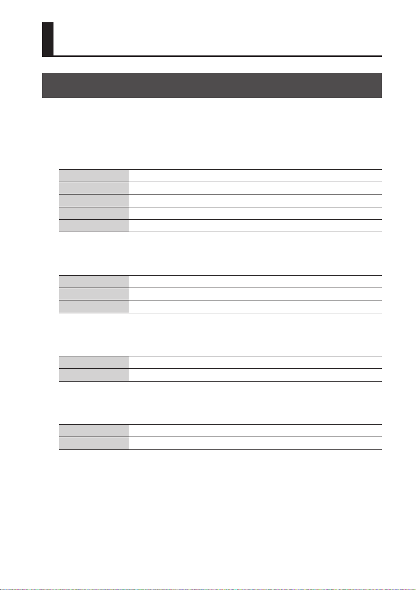
Appendices
Main Specications
Input/Output formats
Refer to “About Input/Output Formats” (p. 18).
Input connectors
SDI BNC type x 1 (combined use with one output connector)
HDMI/DVI Type A (19 pins) x 1
RGB/YPbPr 15-pin mini D-Sub type x 1
VIDEO RCA phono type x 1
AUDIO RCA phono type x 1 pair (L/R) (combined use with output jacks)
Output connectors
SDI BNC type x 2 (one in combined use with input connector)
HDMI Type A (19 pins) x 1
AUDIO RCA phono type x 1 pair (L/R) (combined use with input jacks)
Other connectors
Reference (REF IN) BNC type x 1
USB Type B (Hi-Speed USB) x 1
Signal standards
SDI SMPTE 424M (SMPTE 425M-AB), SMPTE 292M, SMPTE 259M-C
Reference (REF IN) Black Burst, bi-level/tri-level
27
Page 28
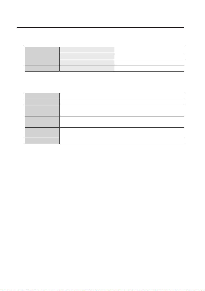
Appendices
Signal level/impedance
Nominal Input Level -6 dBV
Analog Audio
Reference (REF IN) Output Impedance 75 Ω
Maximum Input Level +6 dBV
Input Impedance 22 kΩ
Others
Power Supply DC 9 V (AC Adaptor)
Power Consumption 18 W
Dimensions
Weight
Operation
Temperature
Accessories AC adaptor, Power Cord, Rubber Foot (four), Owner’s Manual
* In the interest of product improvement, the specications and/or appearance of this unit are
subject to change without prior notice.
150 (W) x 130 (D) x 30 (H) mm
5-15/16 (W) x 5-1/8 (D) x 1-3/16 (H) inches
500 g
1 lb 2 oz (excluding AC adaptor)
degrees Celsius
±0–+40
28
Page 29
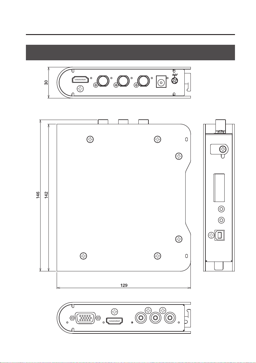
Dimensions
Appendices
Unit: mm
29
Page 30

Appendices
Troubleshooting
Nothing is output from the SDI OUT connector.
Is an HDCP-applied signal being input via the HDMI IN connector?
The VC-1-SC supports HDCP, and when an HDCP-applied signal is input, output via the SDI OUT
connector stops. When this happens, output is made only via the HDMI OUT connector.
No audio from the HDMI IN connector is output.
Does the connected HDMI source device support linear PCM output?
The VC-1-SC supports linear PCM at only 48 kHz. Accordingly, if a dierent format is input, audio
might not be output.
After a period of no operation, the unit turned itself o.
Is the AUTO OFF function activated?
By default, the AUTO OFF function is set to ON. When the unit is to be left powered up for a long
time, set mode switch 10 to “OFF” to turn o the AUTO OFF function.
Settings cannot be changed using the mode switches.
Is mode switch 10 at the “ON” position?
When making setting changes, be sure to set switch 10 to “OFF.”
The volume level of the equipment connected to AUDIO IN/OUT jacks is too
low.
Could you be using a connection cable that contains a resistor?
Use a connection cable that does not contain a resistor.
30
Page 31
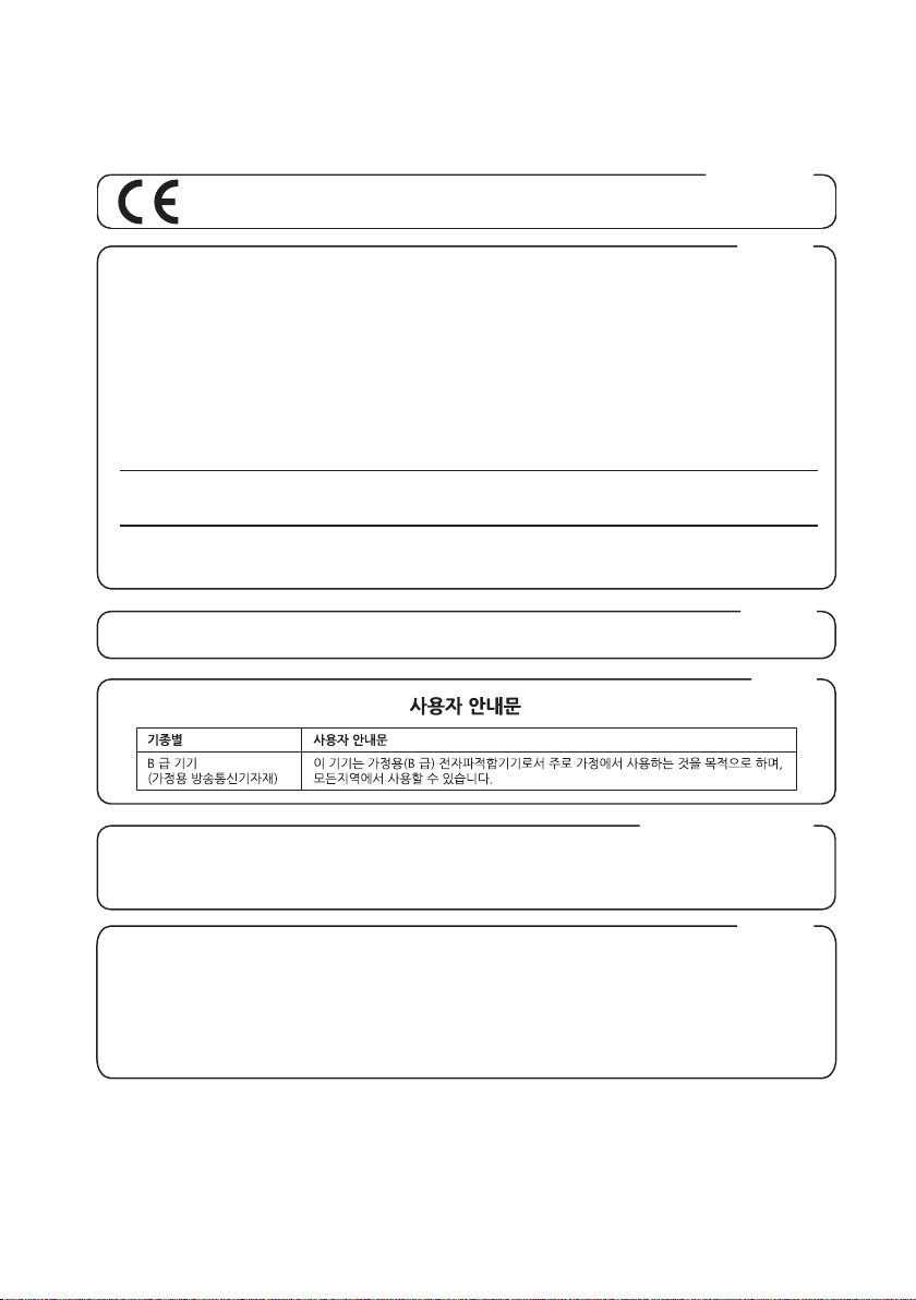
For EU Countries
This product complies with the requirements of EMC Directive 2004/108/EC.
For the USA
FEDERAL COMMUNICATIONS COMMISSION
RADIO FREQUENCY INTERFERENCE STATEMENT
This equipment has been tested and found to comply with the limits for a Class B digital device, pursuant to Part 15 of the
FCC Rules. These limi ts are designed to prov ide reasonable protection against har mful interference in a residential
installation. This equipment generates, uses, and can radiate radio frequency energy and, if not installed and used in
accordance with the instructions, may cause harmful interference to radio communications. However, there is no guarantee
that interference will not occur in a particular installation. If this equipment does cause harmful interference to radio or
television reception, which can be determined by turning the equipment off and on, the user is encouraged to try to correct the
interference by one or more of the following measures:
– Reorient or relocate the receiving antenna.
– Increase the separation between the equipment and receiver.
– Connect the equipment into an outlet on a circuit different from that to which the receiver is connected.
– Consult the dealer or an experienced radio/TV technician for help.
This device complies with Part 15 of the FCC Rules. Operation is subject to the following two conditions:
(1) this device may not cause harmful interference, and
(2) this device must accept any interference received, including interference that may cause undesired operation.
This equipment requires shielded interface cables in order to meet FCC class B limit.
Any unauthorized changes or modifications not expressly approved by the party responsible for compliance could void the user’s
authority to operate the equipment.
For Canada
CAN ICES-3 (B)/NMB-3 (B)
For Korea
For C.A. US (Proposition 65
WARNING
This product contains chemicals known to cause cancer, birth defects and other reproductive harm, including lead.
DECLARATION OF CONFORMITY
Compliance Information Statement
Model Name :
Type of Equipment :
Responsible Party :
Address :
Telephone :
VC-1-SC
Video Converter
Roland Systems Group U.S.
5100 S.Eastern Avenue, Los Angeles, CA 90040-2938, U.S.A.
(323) 890 3700
)
For the USA
31
Page 32
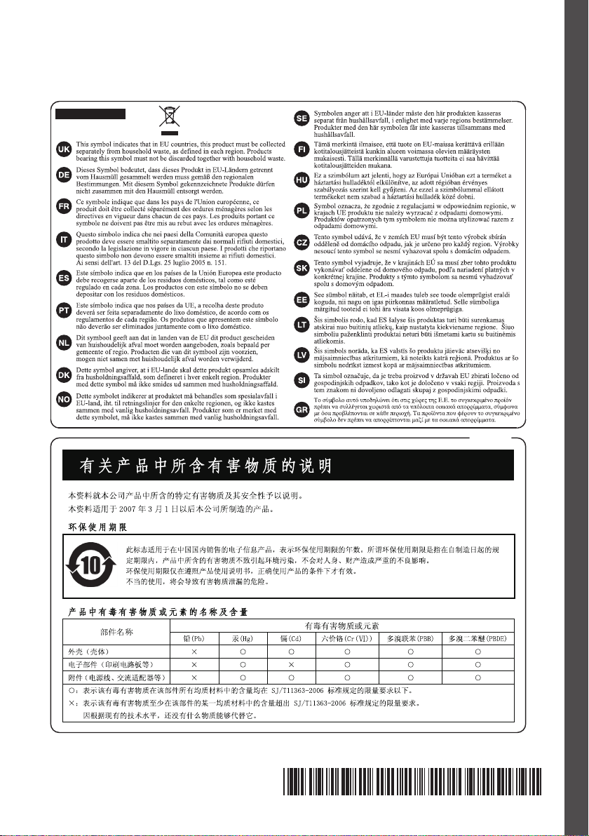
For EU Countries
For China
* 5 1 0 0 0 3 3 7 1 2 - 0 1 *
 Loading...