

Page 1
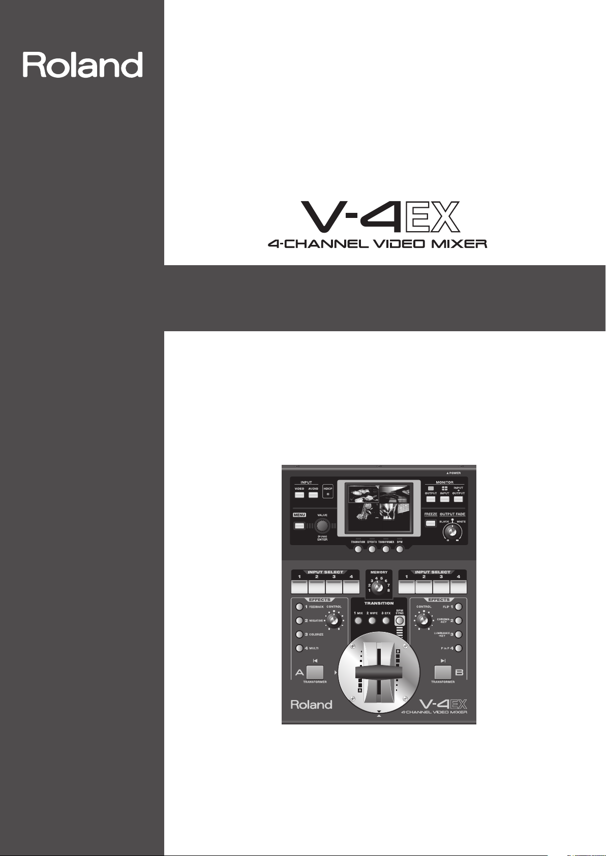
Owner's Manual
Before using this unit, carefully read the sections entitled “USING THE UNIT SAFELY” (p. 3) and
“IMPORTANT NOTES” (p. 5). These sections provide important information concerning the
proper operation of the unit. Additionally, in order to feel assured that you have gained a good
grasp of every feature of your new unit, owner’s manual should be read in its entirety. This manual
should be saved and kept on hand as a convenient reference.
Copyright © 2012 ROLAND CORPORATION
All rights reserved. No part of this publication may be reproduced in any form without the written
permission of ROLAND CORPORATION.
* Roland is either registered trademark or trademark of Roland Corporation in the United States and/or other countries.
* All product names mentioned in this document are trademarks or registered trademarks of their respective owners.
Page 2

2
Page 3
USING THE UNIT SAFELY
WARNING
001-60
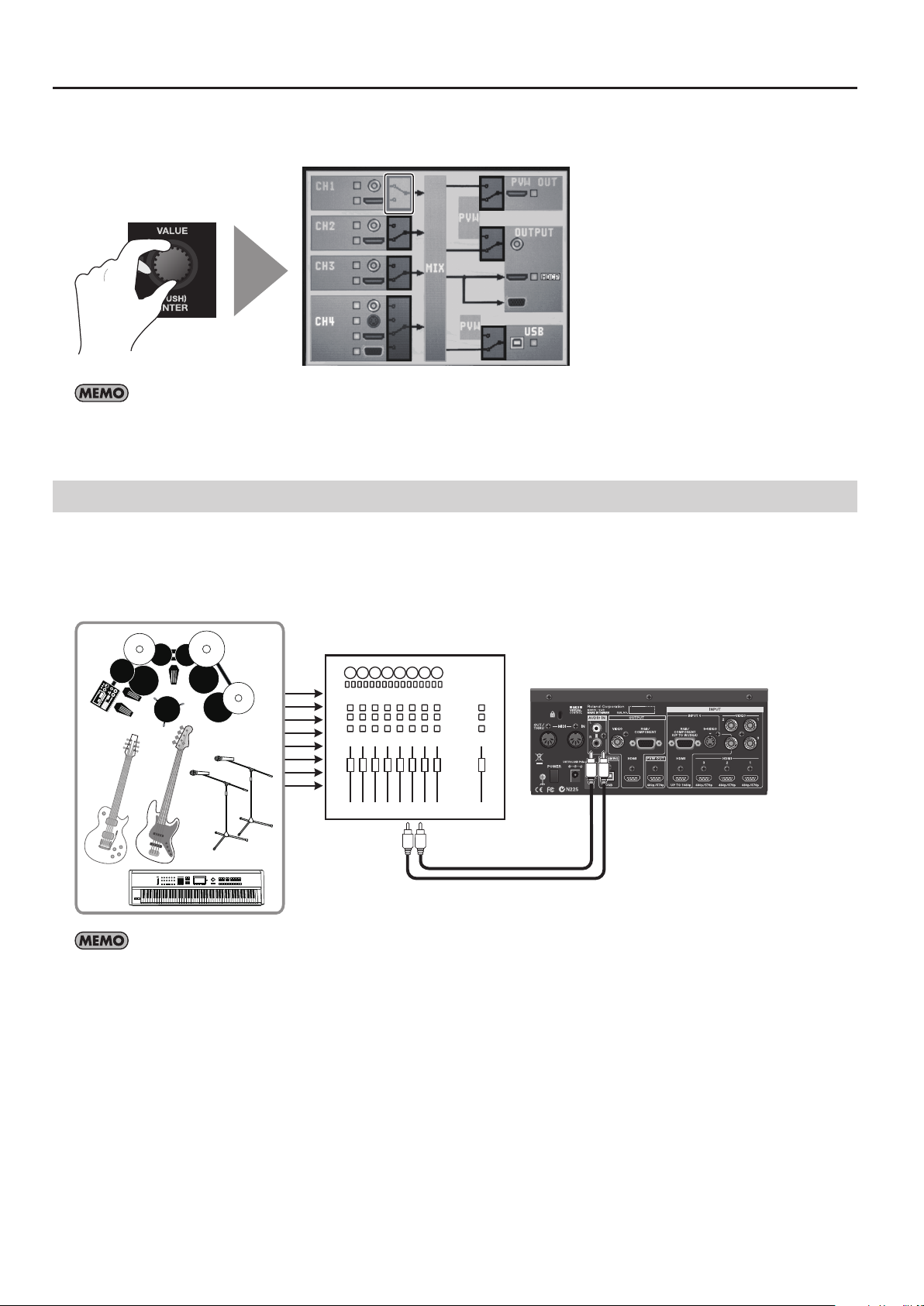
To completely turn o power to the unit, pull out
the plug from the outlet
• Even with the power switch turned o, this unit is not
completely separated from its main source of power. When
the power needs to be completely turned o, turn o the
power switch on the unit, then pull out the plug from the
outlet. For this reason, the outlet into which you choose to
connect the power cord’s plug should be one that is within
easy reach and readily accessible.
001-70
Concerning the AUTO OFF function
• The power to this unit will be turned o automatically
after a predetermined amount of time has passed
since its buttons or controls were last operated (AUTO
OFF function).
automatically, disengage the AUTO OFF function (p. 10).
002d
Do not disassemble or modify by yourself
• Do not open or perform any internal modications on the
unit or its AC adaptor. (The only exception would be where
this manual provides specic instructions which should be
followed in order to put in place the video fader; see p. 57.)
003
Do not repair or replace parts by yourself
• Do not attempt to repair the unit, or replace parts within
it (except when this manual provides specic instructions
directing you to do so). Refer all servicing to your retailer,
the nearest Roland Service Center, or an authorized Roland
distributor, as listed on the “Information” sheet.
004
Do not use or store in the following types of
locations
• Subject to temperature extremes (e.g., direct sunlight in
an enclosed vehicle, near a heating duct, on top of heatgenerating equipment); or are
• Damp (e.g., baths, washrooms, on wet oors); or are
• Exposed to steam or smoke; or are
• Subject to salt exposure; or are
• Humid; or are
• Exposed to rain; or are
• Dusty or sandy; or are
• Subject to high levels of vibration and shakiness.
If you do not want the power to be turned o
WARNING
007
Do not place in an unstable location
• Make sure you always have the unit placed so it is level and
sure to remain stable. Never place it on stands that could
wobble, or on inclined surfaces.
008c
Use only the supplied AC adaptor and the correct
voltage
• Be sure to use only the AC adaptor supplied with the unit.
Also, make sure the line voltage at the installation matches
the input voltage specied on the AC adaptor’s body. Other
AC adaptors may use a dierent polarity, or be designed
for a dierent voltage, so their use could result in damage,
malfunction, or electric shock.
008e
Use only the supplied power cord
• Use only the attached power-supply cord. Also, the supplied
power cord must not be used with any other device.
009
Do not bend the power cord or place heavy
objects on it
• Do not excessively twist or bend the power cord, nor
place heavy objects on it. Doing so can damage the cord,
producing severed elements and short circuits. Damaged
cords are re and shock hazards!
011
Don’t allow foreign objects or liquids to enter
unit; never place containers with liquid on unit
• Do not place containers containing liquid (e.g., ower vases)
on this product. Never allow foreign objects (e.g., ammable
objects, coins, wires) or liquids (e.g., water or juice) to enter
this product. Doing so may cause short circuits, faulty
operation, or other malfunctions.
3
Page 4
USING THE UNIT SAFELY
WARNING
012b
Turn o the unit if an abnormality or malfunction
occurs
• Immediately turn the unit o, remove the AC adaptor from
the outlet, and request servicing by your retailer, the nearest
Roland Service Center, or an authorized Roland distributor,
as listed on the “Information” sheet when:
• The AC adaptor, the power-supply cord, or the plug has
been damaged; or
• If smoke or unusual odor occurs; or
• Objects have fallen into, or liquid has been spilled onto
the unit; or
• The unit has been exposed to rain (or otherwise has
become wet); or
• The unit does not appear to operate normally or exhibits
a marked change in performance.
013
Adults must provide supervision in places where
children are present
• When using the unit in locations where children are present,
be careful so no mishandling of the unit can take place. An
adult should always be on hand to provide supervision and
guidance.
014
Do not drop or subject to strong impact
• Protect the unit from strong impact.
(Do not drop it!)
015
Do not share an outlet with an unreasonable
number of other devices
• Do not force the unit’s power-supply cord to share an
outlet with an unreasonable number of other devices. Be
especially careful when using extension cords - the total
power used by all devices you have connected to the
extension cord’s outlet must never exceed the power rating
(watts/amperes) for the extension cord. Excessive loads can
cause the insulation on the cord to heat up and eventually
melt through.
016
Do not use overseas
• Before using the unit in overseas, consult with your retailer,
the nearest Roland Service Center, or an authorized Roland
distributor, as listed on the “Information” sheet.
022b
Turn the unit o before removing the video fader
• Always turn the unit o and unplug the AC adaptor before
attempting to remove the video fader (p. 57).
CAUTION
101b
Place in a well ventilated location
• The unit and the AC adaptor should be located so their
location or position does not interfere with their proper
ventilation.
102c
When disconnecting an AC adaptor, grasp it by
the plug
• To prevent conductor damage, always grasp the AC adaptor
by its plug when disconnecting it from this unit or from a
power outlet.
CAUTION
103b
Periodically clean the AC adaptor’s plug
• At regular intervals, you should unplug the AC adaptor
and clean it by using a dry cloth to wipe all dust and other
accumulations away from its prongs. Also, disconnect the
power plug from the power outlet whenever the unit is
to remain unused for an extended period of time. Any
accumulation of dust between the power plug and the
power outlet can result in poor insulation and lead to re.
104
Manage cables for safety
• Try to prevent cords and cables from becoming entangled.
Also, all cords and cables should be placed so they are out
of the reach of children.
106
Avoid climbing on top of the unit, or placing
heavy objects on it
• Never climb on top of, nor place heavy objects on the unit.
107c
Do not connect or disconnect the AC adaptor
with wet hands
• Never handle the AC adaptor or its plugs with wet hands
when plugging into, or unplugging from, an outlet or this
unit.
108b
Disconnect everything before moving the unit
• Before moving the unit, disconnect the AC adaptor and all
cords coming from external devices.
109b
Unplug the AC adaptor from the outlet before
cleaning
• Before cleaning the unit, turn it o and unplug the AC
adaptor from the outlet (p. 9).
110b
If there is a possibility of lightning strike,
disconnect the AC adaptor from the outlet
• Whenever you suspect the possibility of lightning in your
area, disconnect the AC adaptor from the outlet.
118d
Keep small items out of the reach of children
• To prevent accidental ingestion of the parts listed below,
always keep them out of the reach of small children.
• Included Parts
RCA - BNC conversion plug
• Removable Parts
Screw for the video fader (p. 57)
118e
Handle the ground terminal carefully
• If you remove the screw from the ground terminal, be
sure to replace it; don’t leave it lying around where it
could accidently be swallowed by small children. When
refastening the screw, make that it is rmly fastened, so it
won’t come loose.
4
Page 5

IMPORTANT NOTES
Power Supply
301 (QA-EMC)
• Do not connect this unit to same electrical outlet that is being used
by an electrical appliance that is controlled by an inverter or a motor
(such as a refrigerator, washing machine, microwave oven, or air
conditioner). Depending on the way in which the electrical appliance
is used, power supply noise may cause this unit to malfunction or may
produce audible noise. If it is not practical to use a separate electrical
outlet, connect a power supply noise lter between this unit and the
electrical outlet.
302
• The AC adaptor will begin to generate heat after long hours of
consecutive use. This is normal, and is not a cause for concern.
307
• To prevent malfunction and equipment failure, always make sure
to turn o the power on all your equipment before you make any
connections.
Placement
351 (QA-EMC)
• Using the unit near power ampliers (or other equipment containing
large power transformers) may induce hum. To alleviate the problem,
change the orientation of this unit; or move it farther away from the
source of interference.
352a (QA-EMC)
• This device may interfere with radio and television reception. Do not
use this device in the vicinity of such receivers.
352b (QA-EMC)
• Noise may be produced if wireless communications devices, such as cell
phones, are operated in the vicinity of this unit. Such noise could occur
when receiving or initiating a call, or while conversing. Should you
experience such problems, you should relocate such wireless devices so
they are at a greater distance from this unit, or switch them o.
354a
• Do not expose the unit to direct sunlight, place it near devices that
radiate heat, leave it inside an enclosed vehicle, or otherwise subject it
to temperature extremes. Excessive heat can deform or discolor the unit.
355b
• When moved from one location to another where the temperature
and/or humidity is very dierent, water droplets (condensation) may
form inside the unit. Damage or malfunction may result if you attempt
to use the unit in this condition. Therefore, before using the unit, you
must allow it to stand for several hours, until the condensation has
completely evaporated.
360
• Depending on the material and temperature of the surface on which
you place the unit, its rubber feet may discolor or mar the surface.
You can place a piece of felt or cloth under the rubber feet to prevent
this from happening. If you do so, please make sure that the unit will
not slip or move accidentally.
361
• Do not place containers or anything else containing liquid on top of
this unit. Also, whenever any liquid has been spilled on the surface of
this unit, be sure to promptly wipe it away using a soft, dry cloth.
Maintenance
401a
• For everyday cleaning wipe the unit with a soft, dry cloth or one that
has been slightly dampened with water. To remove stubborn dirt, use
a cloth impregnated with a mild, non-abrasive detergent. Afterwards,
be sure to wipe the unit thoroughly with a soft, dry cloth.
402
• Never use benzine, thinners, alcohol or solvents of any kind, to avoid
the possibility of discoloration and/or deformation.
Repairs and Data
452
• Please be aware that all data contained in the unit’s memory may
be lost when the unit is sent for repairs. Important settings should
be written down on paper (when possible). During repairs, due care
is taken to avoid the loss of data. However, in certain cases (such as
when circuitry related to memory itself is out of order), we regret that
it may not be possible to restore the data, and Roland assumes no
liability concerning such loss of data.
Additional Precautions
551
• Please be aware that the contents of memory can be irretrievably
lost as a result of a malfunction, or the improper operation of the
unit. To protect yourself against the risk of losing important data, we
recommend that you periodically write your setting down on paper.
552
• Unfortunately, it may be impossible to restore the contents of data
that was stored in the unit’s memory once it has been lost. Roland
Corporation assumes no liability concerning such loss of data.
553
• Use a reasonable amount of care when using the unit’s buttons,
sliders, or other controls; and when using its jacks and connectors.
Rough handling can lead to malfunctions.
554
• Never strike or apply strong pressure to the display.
556
• When disconnecting all cables, grasp the connector itself - never pull
on the cable. This way you will avoid causing shorts, or damage to the
cable’s internal elements.
559a
• When you need to transport the unit, package it in the box (including
padding) that it came in, if possible. Otherwise, you will need to use
equivalent packaging materials.
562
• Some connection cables contain resistors. Do not use cables that
incorporate resistors for connecting to this unit. The use of such cables
can cause the sound level to be extremely low, or impossible to hear.
For information on cable specications, contact the manufacturer of
the cable.
568
• This unit allows you to switch images sat high speed. For some
people, viewing such images can cause headache, nausea, or other
discomfort. Do not use this unit to create video that might cause
these types of health problems. Roland Corporation will accept no
responsibility for any such health problems that may occur in yourself
or in viewers.
About Intellectual Property Rights
Roland
• Roland is an either registered trademark or trademark of Roland
Corporation in the United States and/or other countries.
Others
• Company names and product names appearing in this document are
registered trademarks or trademarks of their respective owners.
C-01-1
• It is forbidden by law to make an audio recording, video recording,
copy or revision of a third party’s copyrighted work (musical work,
video work, broadcast, live performance, or other work), whether in
whole or in part, and distribute, sell, lease, perform, or broadcast it
without the permission of the copyright owner.
C-01-2
• Do not use this product for purposes that could infringe on a
copyright held by a third party. We assume no responsibility
whatsoever with regard to any infringements of third-party copyrights
arising through your use of this product.
C-02
• This product can be used to record or duplicate audio or visual
material without being limited by certain technological copyprotection measures. This is due to the fact that this product is
intended to be used for the purpose of producing original music or
video material, and is therefore designed so that material that does
not infringe copyrights belonging to others (for example, your own
original works) can be recorded or duplicated freely.
MMP
• MMP (Moore Microprocessor Portfolio) refers to a patent portfolio
concerned with microprocessor architecture, which was developed
by Technology Properties Limited (TPL). Roland has licensed this
technology from the TPL Group.
5
Page 6
Check the Included Items
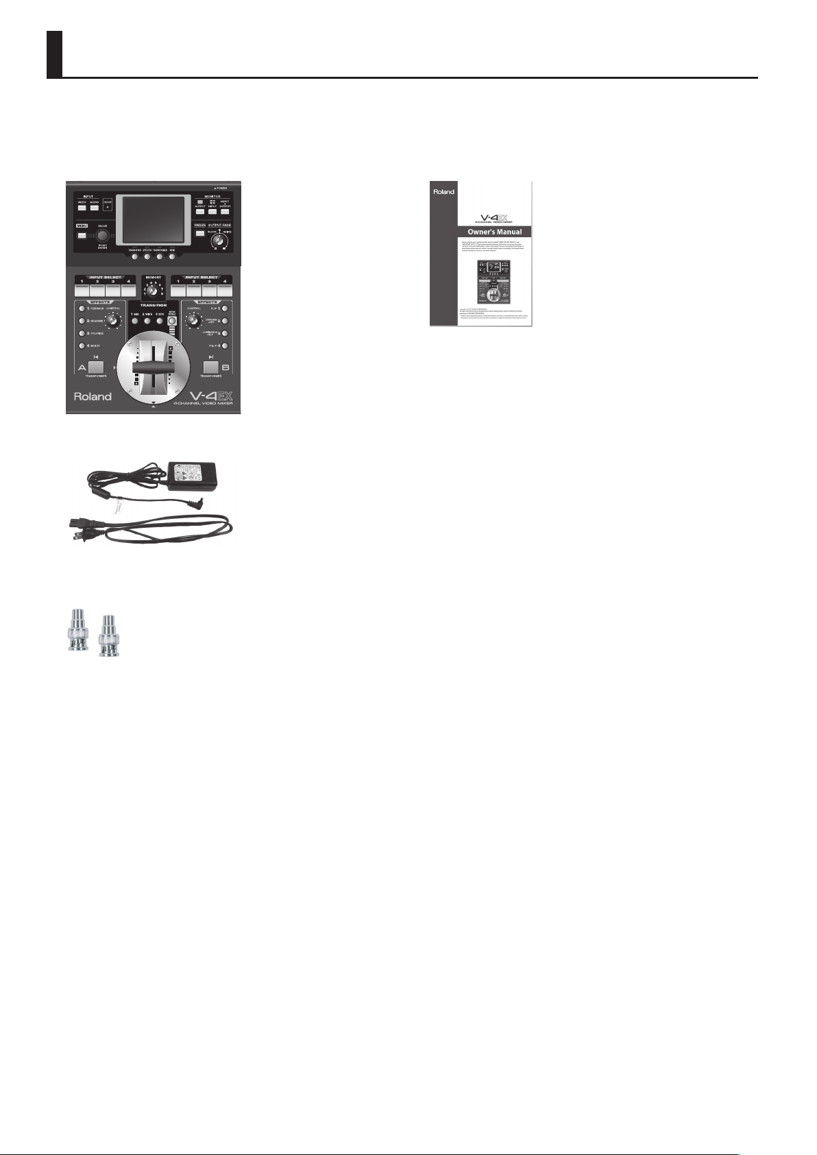
The following items are included. Please make sure that all items are present. If anything is missing, please contact your dealer.
V-4EX itself
g.V-4EX-itself.eps
AC adaptor and power cord
g.PSB1U.eps
Owner’s manual
g.owners-manual.eps
RCA - BNC conversion plug (two)
g.RCA-BNC-plug.eps
The explanations in this manual include illustrations that depict what should typically be shown by the display. Note, however, that
your unit may incorporate a newer, enhanced version of the system (e.g., includes newer sounds), so what you actually see in the
display may not always match what appears in the manual
6
Page 7

Contents
Check the Included Items .....................................................................................6
About the Power Supply ....................................................................................... 9
Connecting the AC Adapter ..............................................................................................................................................................9
About the Cord Hook...........................................................................................................................................................................9
Caution Regarding the Power Supply ...........................................................................................................................................9
Turning the Power On and O ...................................................................................................................................................... 10
Part Names and Functions..................................................................................11
Top Panel ............................................................................................................................................................................................... 11
Rear Panel ............................................................................................................................................................................................. 14
Connecting External Equipment ........................................................................15
Signal Flow ........................................................................................................................................................................................... 15
Connecting Source Equipment ..................................................................................................................................................... 16
Connecting Video Source Equipment .......................................................................................................................... 16
Switching the Enabled Connector ................................................................................................................................. 17
Connecting Audio Source Equipment ..........................................................................................................................18
Connecting Output Equipment .................................................................................................................................................... 19
Connecting a Projector or Recording Unit .................................................................................................................. 19
Connecting a Preview Monitor ........................................................................................................................................ 19
Connecting a Computer for Streaming ........................................................................................................................ 20
Checking the Connections ............................................................................................................................................................. 22
About Input/Output Formats .............................................................................23
Inputting HDCP Signals ......................................................................................24
Basic Operations .................................................................................................25
Switching the Monitor View Mode .............................................................................................................................................. 25
Changing Various Settings ............................................................................................................................................................. 26
Switching the Video .......................................................................................................................................................................... 27
Switching the Picture Using the Video Fader ............................................................................................................. 27
Switching Using the Touch Panel ................................................................................................................................... 28
Switching Using the Transformer Buttons...................................................................................................................29
Switching Automatically in Time with the Musical Rhythm ................................................................................. 29
Applying Fade to Final Output ...................................................................................................................................................... 31
Freezing the Final Output ............................................................................................................................................................... 31
About AUTO SCAN Function .......................................................................................................................................................... 31
Applying Filter Eects to Video .........................................................................32
Compositing Two Pictures ..................................................................................33
Key Compositing ................................................................................................................................................................................ 33
Compositing Using Chroma Key .....................................................................................................................................33
Compositing Using Luminance Key ..............................................................................................................................34
Compositing Using Picture-in-Picture ........................................................................................................................................ 35
7
Page 8

Contents
About Other Features .........................................................................................36
Adjusting the Audio Balance/Volume ........................................................................................................................................ 36
Aligning the Timing of Video and Audio (Lip-sync) ............................................................................................................... 37
About AUDIO FOLLOW Function .................................................................................................................................................. 37
Saving Settings ................................................................................................................................................................................... 38
Making the Settings for Video Fader Operation ..................................................................................................................... 39
Menu Operations and Menu List ........................................................................40
Menu Operations ............................................................................................................................................................................... 40
Menu List ............................................................................................................................................................................................... 41
Appendices ..........................................................................................................45
Main Specications ........................................................................................................................................................................... 45
Eects List ............................................................................................................................................................................................. 46
Calibrating and Changing the Installed Orientation of the Video Fader ....................................................................... 56
About Remote Control ..................................................................................................................................................................... 58
Security Slot ......................................................................................................................................................................................... 58
Dimensions .......................................................................................................................................................................................... 58
Troubleshooting ................................................................................................................................................................................. 59
Index ....................................................................................................................60
8
Page 9
About the Power Supply
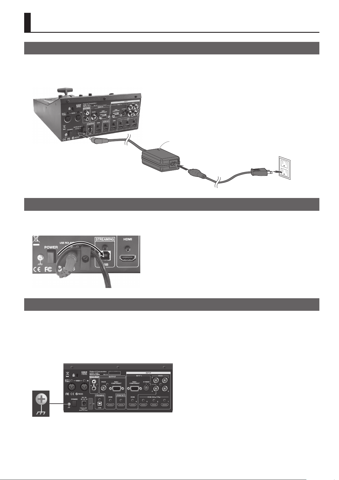
Connecting the AC Adapter
Connect the AC adapter as shown in the gure below.Place the AC adaptor so the side with the indicator (see illustration) faces
upwards and the side with textual information faces downwards.
* The indicator will light when you plug the AC adaptor into an AC outlet.
g.connect-PSB1U.eps
Indicator
About the Cord Hook
To prevent the inadvertent disruption of power to your unit (should the plug be pulled out accidentally), and to avoid applying
undue stress to the DC IN connector, anchor the power cord using the cord hook, as shown in the illustration.
g.cord-hook.eps
Caution Regarding the Power Supply
Depending on the circumstances of a particular setup, you may experience a discomforting sensation or perceive that the surface
feels gritty to the touch when you touch this device or the metal portions of a video camera, monitor, or other devices connected
to it. This is due to an innitesimal electrical charge, which is absolutely harmless. However, if you are concerned about this,
connect the ground terminal (see gure) to an external ground. When the unit is grounded, a slight hum may occur, depending
on the particulars of your installation. If you are unsure of the connection method, contact the nearest Roland Service Center or an
authorized Roland distributor.
g.earth-terminal.eps
Unsuitable places for connection
• Water pipes (may result in shock or electrocution)
• Gas pipes (may result in re or explosion)
• Telephone-line ground or lightning rod (may be dangerous in the event of lightning)
9
Page 10
About the Power Supply
Turning the Power On and O
Once everything is properly connected, be sure to follow the procedure below to turn on their power. If you turn on equipment in
the wrong order, you risk causing malfunction or equipment failure.
* This unit is equipped with a protection circuit. A brief interval (a few seconds) after turning the unit on is required before it will operate normally.
Turning the Power On
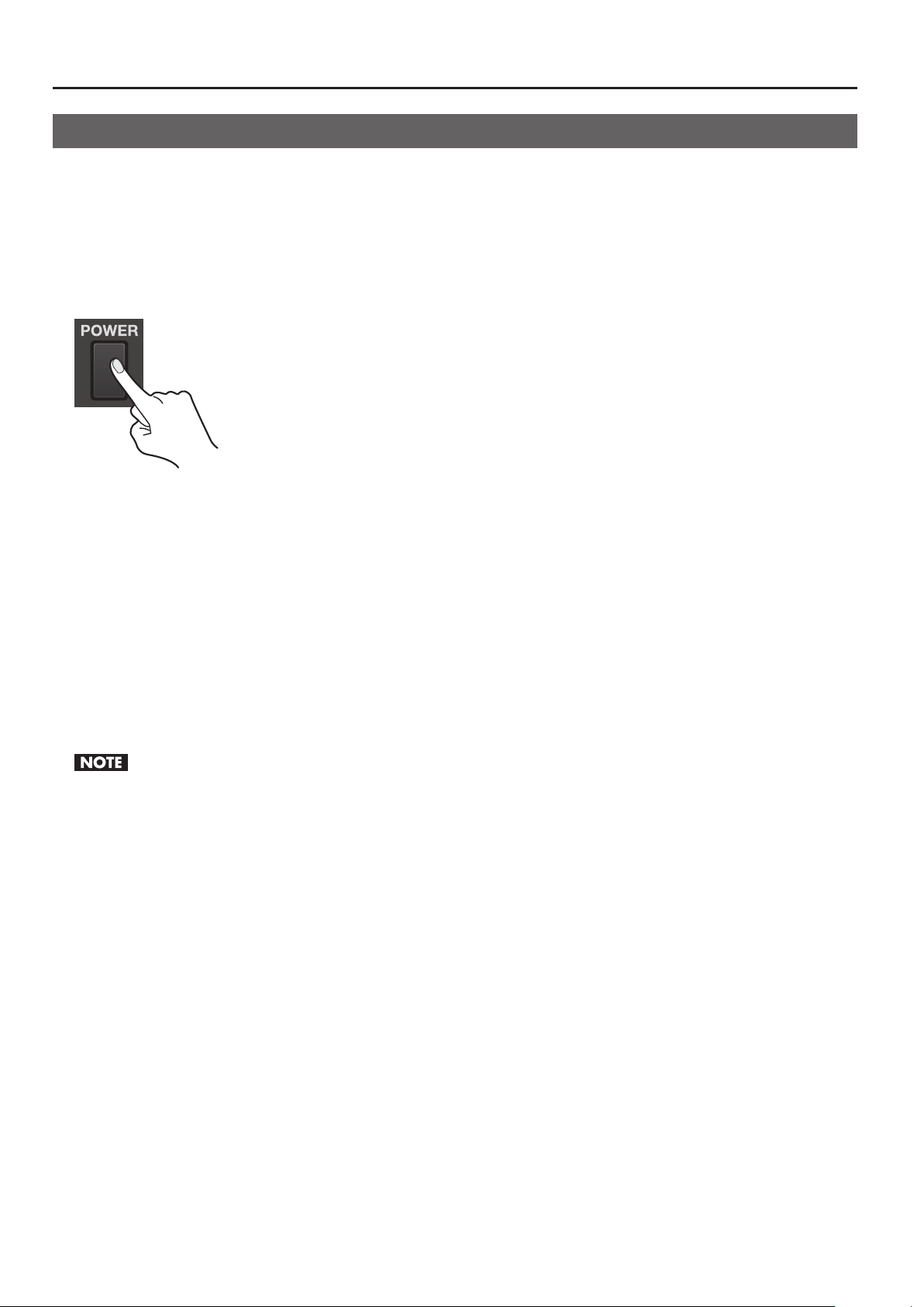
Make sure the power cable is securely inserted, then press the [POWER] button located on the rear panel. The buttons and
indicators on the top panel ash, and the V-4EX starts up.
g.power-button.eps
Turning the Power O
Press the [POWER] button on the rear panel. The buttons and indicators on the top panel go dark, and the power to the V-4EX is
switched o.
About AUTO OFF
When all of the conditions described below continue for 240 minutes or longer, the V-4EX automatically powers down (AUTO OFF
feature).
• No operation of the unit (including operation by remote control)
• No video input
To keep the power from being turned o automatically, disable the AUTO OFF feature. You can disable the AUTO OFF feature by
going to the [SETUP] menu and setting [AUTO OFF] to [OFF]. Refer to “Menu Operations” (p. 40) and “SETUP Menu” (p. 44).
• Any settings that you are in the process of editing will be lost when the power is turned o. If you have any settings that you want to keep, you
should save them beforehand.
• To restore power, turn the power on again.
10
Page 11
1
Part Names and Functions
Top Panel
g.top-panel.eps
2
3
4
5
11
12
13
6
7
8
9
10
14
15
16
17
18
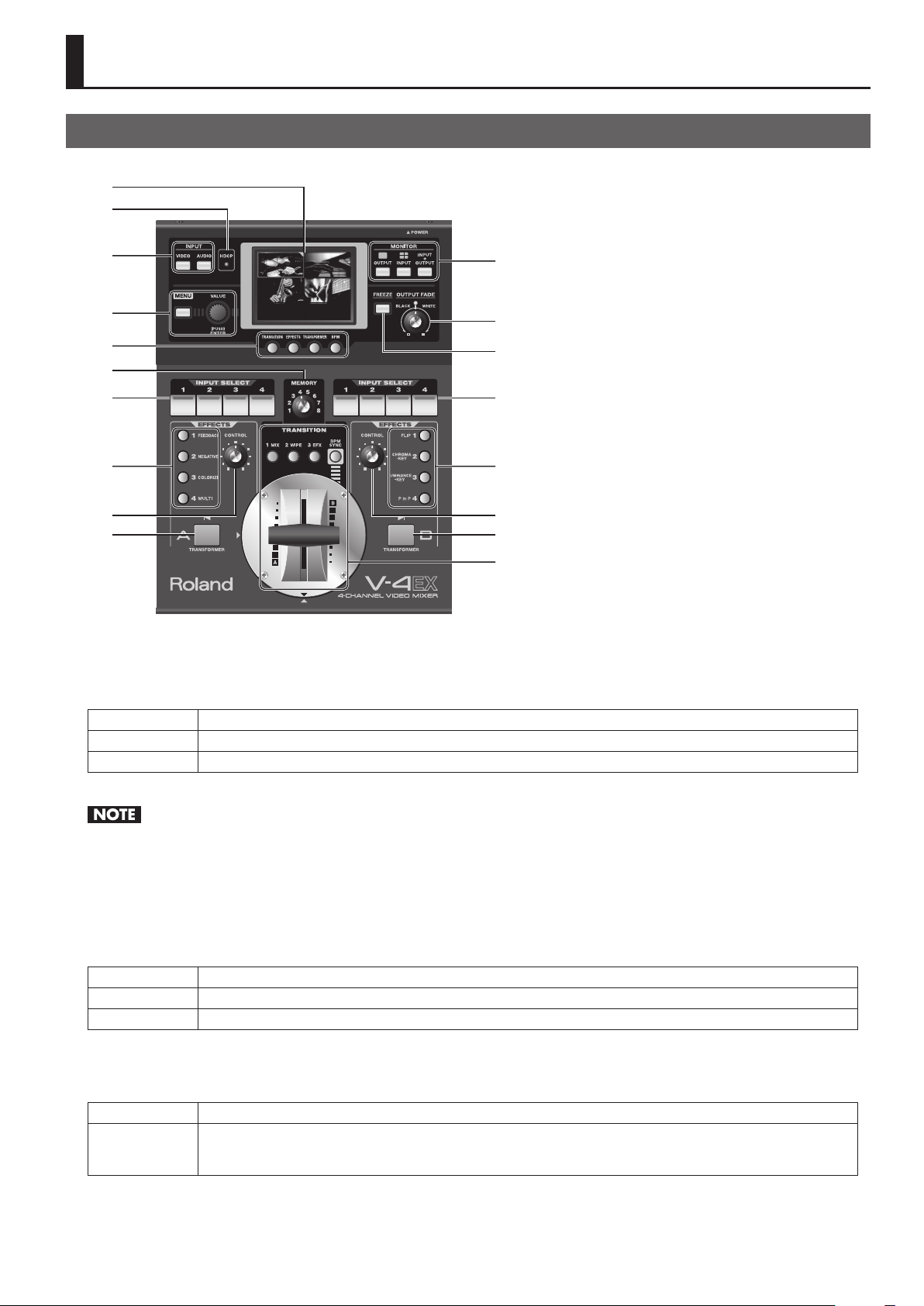
1 Monitor
This displays video from source equipment or the video output from the V-4EX. You can select a view mode from below by pressing
the MONITOR buttons.
OUTPUT This displays the current video output from the V-4EX on a single screen.
INPUT This displays video input from source equipment on a four-way split screen.
INPUT + OUTPUT
This displays the current video output as an inset screen on a four-way split screen displaying the input from source equipment.
You can also use the touch panel to switch the video.
Note the following points when you switch video using the touch panel.
• Move the video fader all the way to the end of its stroke. The bus of one end is the target for switching. The touch panel cannot be used for
switching if the fader has not been moved all the way to one end.
• The touch panel cannot be used for switching while the menu screen is displayed. Exit the menu when you switch using the touch panel.
2 HDCP Indicator
This operates as described below, depending on the HDCP setting (p. 24).
Lighted It lights up when an HDCP-compatible device is connected as the output device.
Flashing It ashes when no output device is connected or when the connected device is not compatible with HDCP.
Unlighted It goes dark when the V-4EX’s HDCP-signal input/output mode is o.
3 INPUT Buttons
Pressing one of these displays the input/output setting screen for video or audio.
VIDEO This determines the assignments to channels 1 through 4. For each channel, you can select the enabled input connector.
This displays the mixing settings for audio. With the V-4EX, you can output video and audio together (embedded audio) from
AUDIO
the HDMI connector and USB port. Use this to perform balance/volume adjustment (p. 36) and set the amount of delay for
audio (p. 37).
4 MENU Button and VALUE Dial
Use these to display the menu screen and make various settings for the V-4EX (p. 40).
11
Page 12

Part Names and Functions
5 Setup Buttons
Use these to make the settings for transition eects, lter eects etc. (p. 26).
6 MEMORY Dial
You can save the current settings of the V-4EX to the dierent positions on the dial (p. 37).
* When [1] has been selected, settings can be changed, but cannot be saved.
7 A-bus Input Selectors
These select the channel to be sent to A-bus.
8 A-bus Eect Buttons
These apply eects to the video sent to A-bus.
* By default, from top down, the assigned eects are Strobe, Negative, Colorize, and Multi.
9 A-bus Eect Control Dial
This changes the amount of eect applied to the video on A-bus in a smooth and continuous manner.
10 A-bus Transformer
Pressing this performs a transition for the video on A-bus. The video on A-bus is displayed while the button is depressed (p. 29).
* By default, the transition is made using a cut. You can also use menu settings to apply a transition eect.
11 MONITOR Buttons
These switch the view mode for the monitor.
12 OUTPUT FADE Dial
This applies fade to nal output. Turning counterclockwise applies a fade-out to black, and turning clockwise applies a fade-out to
white. To apply a fade-in, return the dial to its center position (p. 31).
* The indicator ashes when the dial is at any position other than center.
13 FREEZE Button
This freezes the nal output. It lights up while the still video is being output. Pressing the control a second time makes it go dark
and ends the output freezing (p. 31).
14 B-bus Input Selectors
These select the channel to be sent to B-bus.
15 B-bus Eect Buttons
These apply eects to the video sent to B-bus.
* By default, from top down, the assigned eects are Mirror, Chroma Key, Luminance Key, and Picture-in-Picture.
16 B-bus Eect Control Dial
This changes the amount of eect applied to the video on B-bus in a smooth and continuous manner.
17 B-bus Transformer
Pressing this performs a transition for the video on A-bus. The video on A-bus is displayed while the button is depressed (p. 29).
* By default, the transition is made using a cut. You can also use menu settings to apply a transition eect.
18 Transition Section
Use this section when switching between the A-bus video and the B-bus video. For information on part names and functions, refer
to the following page.
12
Page 13
Transition Section
g.transition-section.eps
Part Names and Functions
1
3
2
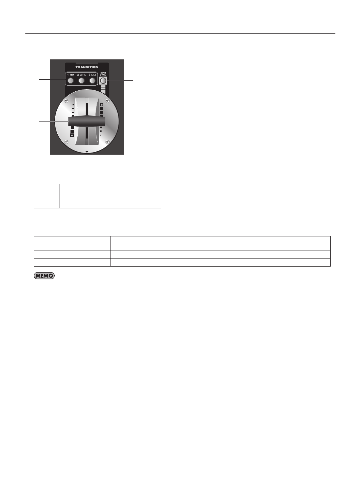
1 Transition Eect Buttons
You can assign transition eects to buttons 1 through 3. By default, the following three types are assigned.
1 MIX The A and B pictures change gradually.
2 WIPE The A and B pictures change using a wipe.
3 EFX The A and B pictures change using a soft wipe.
2 Video Fader
This has the following three applications.
A/B switching
Adjustment of the amount of keying When you are carrying out chroma or luminance key composition, this adjusts the degree of extraction.
Inset screen display-level adjustment When you are carrying out Picture-in-Picture composition, this adjusts the display level of the inset screen.
When no compositing eect is being applied, moving the fader forward or backward switches the video
between A-bus and B-bus.
By default, the video fader is installed vertically (operating front to back), but you can reinstall it horizontally (operating side to side). Refer to
“Changing the Installed Orientation of the Video Fader” (p. 57).
3 BPM SYNC Button
You can make A/B switching or turning eects on/o to occur in sync with the BPM (beats per minute). Pressing this button to
make it light up enables the automatic switching (p. 29).
13
Page 14
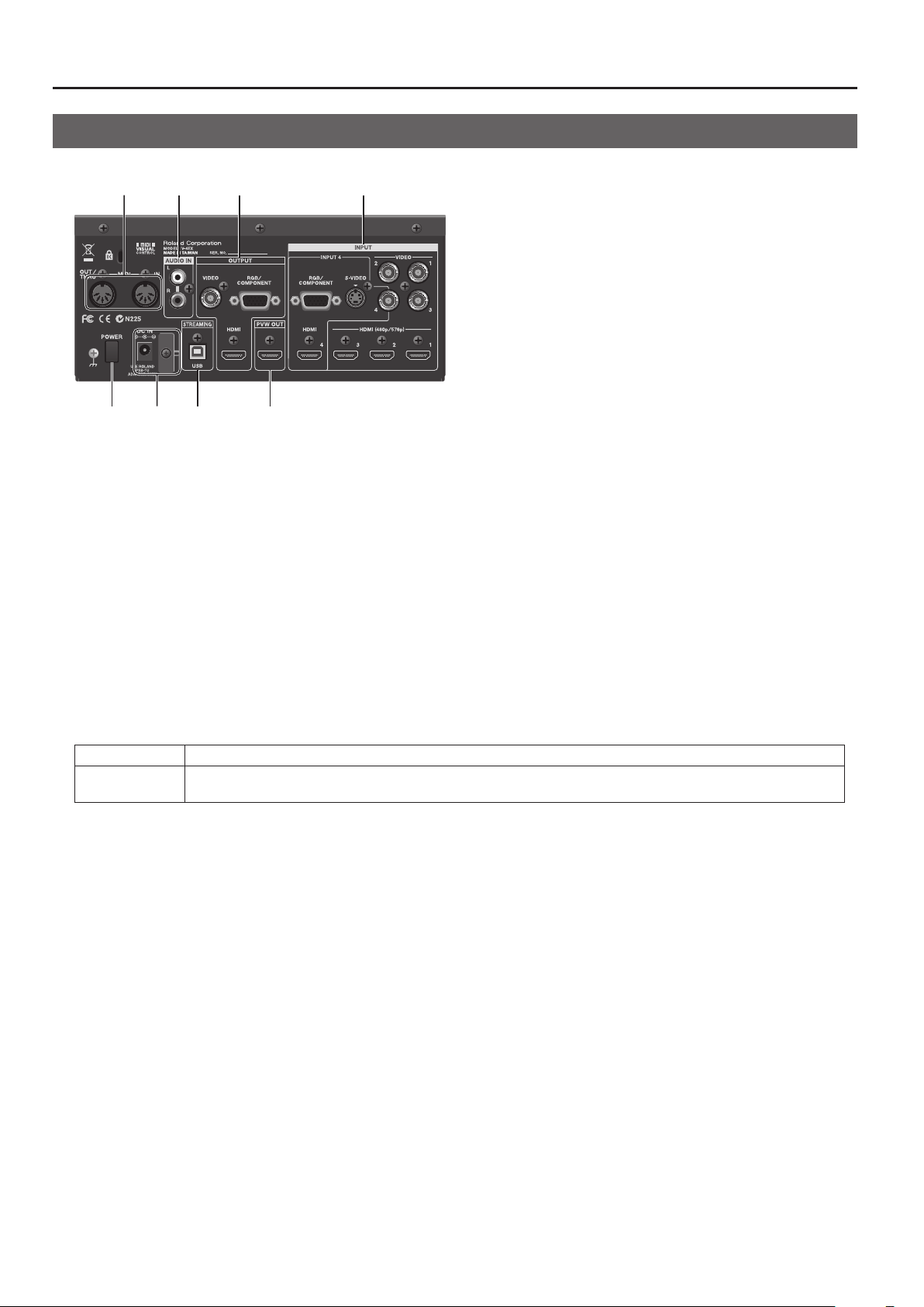
Part Names and Functions
12 34
5678
Rear Panel
g.rear-panel.eps
1 MIDI IN and OUT/THRU Connectors
Use these when remotely controlling the unit from an external MIDI device (a device compatible with MIDI VISUAL CONTROL or the
like), or when using the unit to perform remote control of another device.
2 AUDIO IN Connectors
Use these AUDIO INPUT connectors to connect source equipment for analog audio.
3 OUTPUT Connectors
These connectors output the results of mixing on the V-4EX. Connect a projector or recording equipment. On the V-4EX, you can
output video and audio together (embedded audio) from the HDMI connector and the USB port.
* You can also use the composite connector (VIDEO) to output four-way split video.
4 INPUT Connectors
Connect video source equipment. Sections 1 through 4 are each provided with the connectors below. Use the menus to select the
enabled input connector.
INPUT 1 -- 3 Connect composite (VIDEO) or HDMI sources. By default, HDMI input is enabled for each channel.
INPUT 4
In addition to composite or HDMI, you can also connect sources with S-Video or analog RGB (15-pin mini D-Sub type) outputs.
By default, HDMI input is enabled.
5 POWER Button
This turns the power to the V-4EX on and o.
6 DC IN Connector and Cord Hook
These are for connecting the included AC adapter.
7 USB Port
When streaming output from the V-4EX or remotely controlling the V-4EX from a computer, use USB cable to make the connection
to the computer (p. 20).
8 PVW OUT Connector
Connect a monitor for preview output. You can select an output mode from below.
• Four-way split video. Same as [INPUT] mode for the built-in monitor.
• Final video output. Same as [OUTPUT] for the built-in monitor.
* Output format of the PVW OUT connector is 480/59.94i (when set to NTSC) or 576/50i (when set to PAL).
14
Page 15
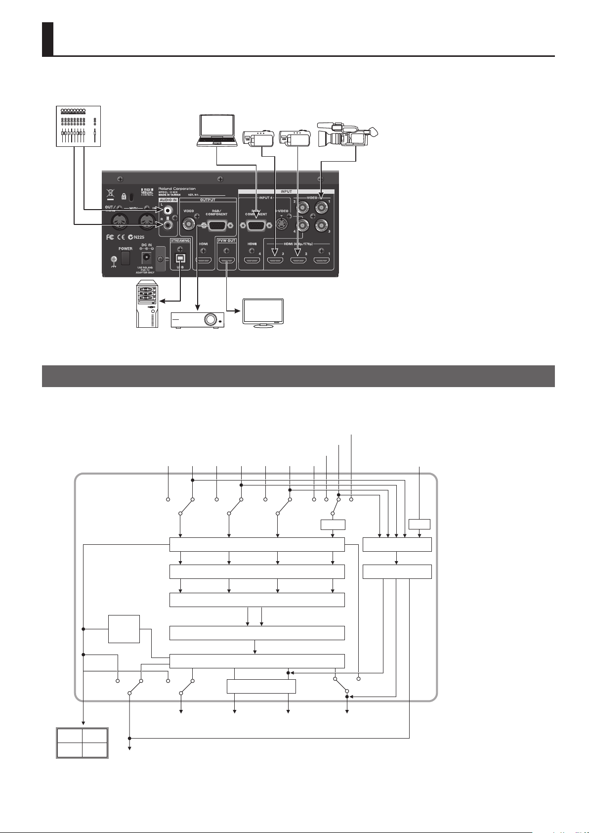
RGB/
Connecting External Equipment
Connect external equipment as shown in this chapter. For information on specic connection methods, refer to the following pages.
* To prevent malfunction and equipment failure, always turn down the volume, and turn o all the units before making any connections.
g.peripheral-connection.eps
For information on signal formats that can be input and output, refer to “About Input/Output Formats” (p. 23).
Signal Flow
The internal signal ow of the V-4EX is as shown below.
g.signal-ow.eps
Component
HDMI
S-Video
Output
+
Input
HDMIVideo
1234
HDMIVideo HDMIVideo
Frame Sync (480p/576p)
Input Selector
A-BUS B-BUS
Video Mixer / PinP / Key / Eect
Video
Scaler
Audio In
Delay
Audio Mixer
Delay
12
34
PVW OUT
Composite
OUT
Output Fade / Freeze
Scaler
RGB/Component
OUT
HDMI OUT
USB OUT
15
Page 16
Connecting External Equipment
Connecting Source Equipment
Regardless of the input resolution of the source device, internal processing by the V-4EX is carried out at 480p (when set to NTSC) or 576p (when set
to PAL).
Almost all equipment capable of HDMI output supports 480/59.94p or 576/50p and can be connected to INPUT 1 through 3 on the V-4EX, but some
devices do not support. If the video from such a source device cannot be input correctly via INPUT 1 through 3, connect the device to INPUT 4.
Connecting Video Source Equipment
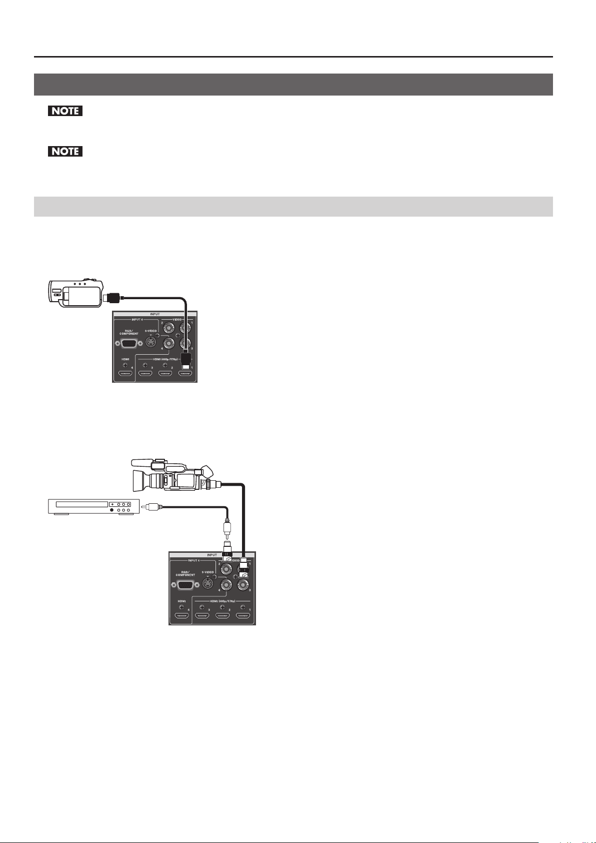
Making HDMI Connections
Connect video cameras or other devices capable of HDMI output to the [HDMI] connector at INPUT 1 through 4.
g.HDMI-connection.eps
Making Composite Connections
Connect video cameras, DVD players, or other devices capable of composite output to the [VIDEO] connectors at INPUT 1 through 4.
* When connecting equipment that has RCA pin type output connectors, use the included RCA-BNC conversion plug.
g.composite-connection.eps
To connect composite source equipment, the enabled connector must be switched from [HDMI] to [VIDEO]. Refer to the following
“Switching the Enabled Connector” and change the setting.
Making S-Video Connections
You can make an S-Video connection at INPUT 4 only. In the same way as for a composite connection, when making an S-Video
connection, the enabled connector must be switched from [HDMI] to [S-VIDEO]. Refer to the following “Switching the Enabled
Connector” and change the setting.
16
Page 17
Connecting External Equipment
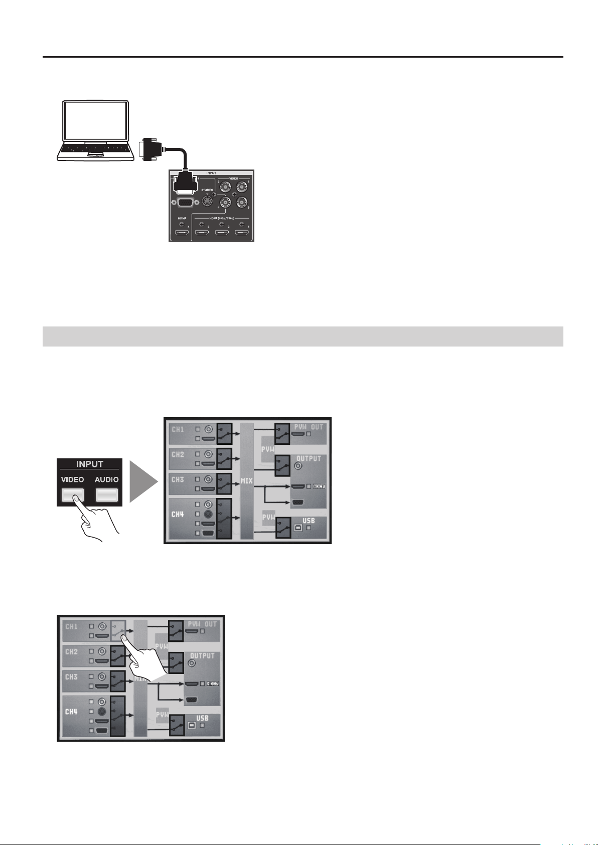
Making an RGB/Component Connection
g.connect-PC-RGB.eps
You can make an RGB/component connection at INPUT 4 only. In the same way as for a composite or S-Video connection, the
enabled connector must be switched from [HDMI] to [RGB/COMPONENT]. Refer to the following “Switching the Enabled Connector”
and change the setting.
* For equipment provided with component output, make the connection using a conversion cable from component to mini D-Sub 15-pin type
connectors.
Switching the Enabled Connector
Use the procedure described below to enable connectors other than HDMI.
1. Display the input setup screen.
Press the [VIDEO] button in INPUT section to display the input setup screen for video.
g.input-video-button.eps
2. Select the channel.
Use the touch panel to select the channel where the non-HDMI source is connected.
* You can also select the channel by turning and pressing the [VALUE] dial.
g.select-composite-ch.eps
17
Page 18
Connecting External Equipment
3. Enable the input.
Turn the [VALUE] dial to change the enabled connector.
g.select-VIDEO.eps
You can also change the enabled connector using the [VIDEO] button and the input selector buttons of A-Bus. Hold down the [VIDEO] button and
press the input selector of the channel you want to change the enabled connector. On channels 1 through 3, switching alternates between HDMI
and composite. Channel 4 is switched in this sequence of : composite -> S-Video -> HDMI -> RGB/component.
Connecting Audio Source Equipment
Connect an audio mixer or other source device to the AUDIO IN connectors. Input made via these connectors is output from the
HDMI connectors and the USB port together with the results of video mixing (embedded audio).
* When connection cables with resistors are used, the volume level of equipment connected to the inputs (AUDIO IN) may be low. If this happens,
use connection cables that do not contain resistors.
g.audio-connection.eps
Audio Mixer
Use the menus to adjust the balance/volume of the audio output (p. 36) or delay its timing to sync with the video (p. 37).
18
Page 19
Connecting External Equipment
Connecting Output Equipment
For information on the signal formats that can be output from the V-4EX, refer to “About Input/Output Formats” (p. 23).
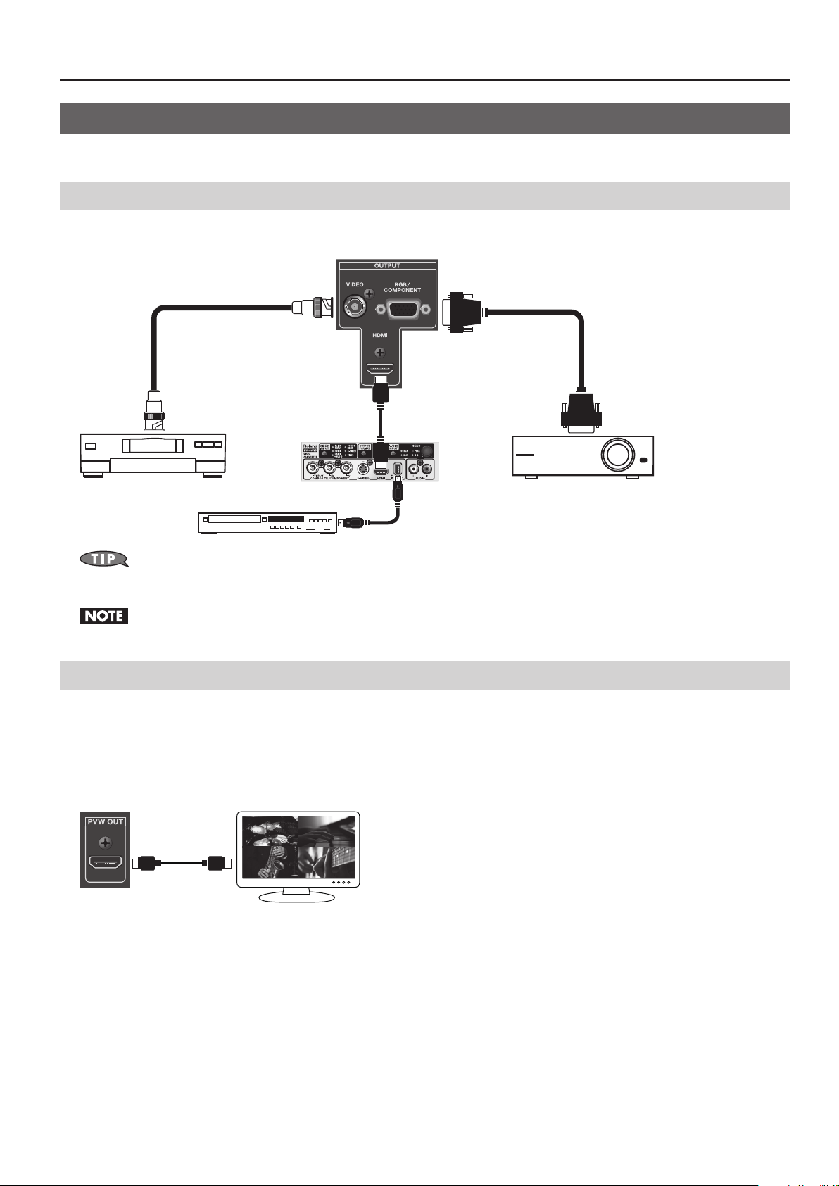
Connecting a Projector or Recording Unit
Make the connections to the [VIDEO], [RGB/COMPONENT], or [HDMI] output connectors.
g.output-connection.eps
You can connect the VC-30HD to HDMI output. Using the i.LINK output of the VC-30HD, you can connect a digital video recorder, Blu-ray Disc
recorder, or other such device.
When HDCP is turned on, composite and RGB/component output is stopped. Note, however, that HDMI output continues (p. 24).
Connecting a Preview Monitor
Connect a preview monitor to the PVW OUT connector. Output from this connector is 480/59.94p (when set to NTSC) or 576/50p
(when set to PAL). Connect a compatible monitor.
You can select the output mode from below.
• Four-way split video. Same as [INPUT] for built-in monitor.
• Final video output. Same as [OUTPUT] for built-in monitor.
g.preview-connection
19
Page 20
Connecting External Equipment
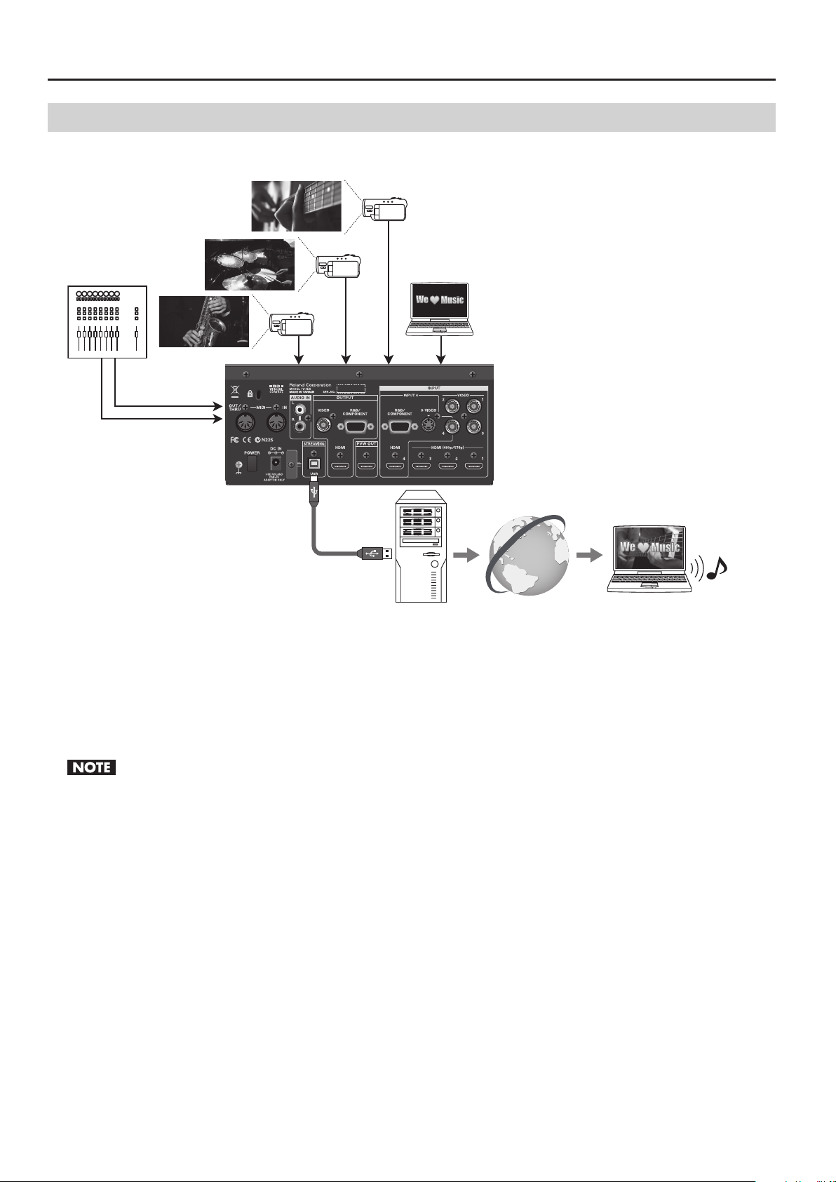
Connecting a Computer for Streaming
You can send video and audio signals to a computer connected to the USB port.
g.PC-USB-connection.eps
Supported Operating Systems
Make connections to computers running the following operating systems.
• Windows XP Home Edition/Professional Edition Service Pack 3 or later
• Windows Vista Service Pack 2 or later
• Windows 7
• Mac OS X 10.6 or later
Connection and operation of the V-4EX with standard computers running the operating systems described above have been veried, but
connection and operation with all computers satisfying such conditions is not assured. Connection or operation may be impossible due to
dierences in setting specications or the usage environment that are specic to the equipment.
20
Page 21
Connecting External Equipment
Making the Connection to a Computer
To make the connection to a computer, carry out the steps described below.
1. Connect a computer.
After starting the V-4EX and the operating system on the computer, use USB cable to connect the USB port on the V-4EX to a USB
port of your computer.
Making the connection through an extension cable or USB hub may result in failure of the computer to detect the V-4EX. We recommend
connecting the V-4EX and computer directly.
2. Wait for communication between the V-4EX and the computer to be established.
A short while after making the connection, communication with the computer starts, and the standard driver for the operating
system is automatically installed. Installing a special driver is not necessary.
* The computer recognizes the V-4EX as a USB video class device/audio class device.
Performing Output to a Computer
For the video and audio signals from the V-4EX to be viewed and heard correctly on the computer, software that supports USB
video class and USB audio class must be installed and set up on the computer.
1. Prepare output of video or audio.
Operate the V-4EX to prepare the video and audio output for the computer.
2. On the computer, check the input from the V-4EX.
Start the program that supports USB video class/audio class, and check the video or audio input from the V-4EX.
You can use the menus to adjust the volume/balance of the audio output (p. 36) or delay its timing to sync with the video (p. 37).
Output Signals
The following signals are output from the USB port on the V-4EX.
Video 720 x 480 pixels (when set to NTSC) or 720 x 576 pixels (when set to PAL)/Motion JPEG
Audio 16 bits/48 kHz/linear PCM
21
Page 22
Connecting External Equipment
Checking the Connections
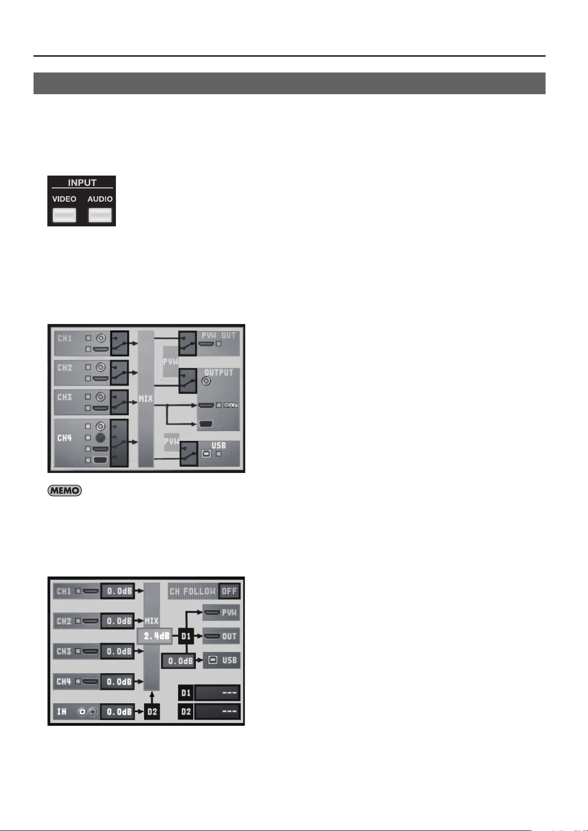
You can check the connections of input and output equipment at the screens described below. To access the checking screens,
press the [VIDEO] button or [AUDIO] button in INPUT section.
* Depending on the input and output connectors used, some connections cannot be checked.
* The checking screen is displayed over the picture on the monitor. You can hide the picture on the monitor by pressing the lighted MONITOR
button to make it go dark.
g.input-buttons.eps
Video Input/Output Equipment
Pressing the [VIDEO] button in INPUT section displays the screen shown below. A yellow box next to the icon for a connector
indicates that the connection is recognized by the V-4EX. If the box is gray, no connection is detected.
* The recognition status (grey or yellow) of CH4’s S-Video and RGB/Component connectors are displayed only while the connector is selected.
When it is not selected, there is no display of box regardless to the recognition status.
g.video-connect-screen.eps
The [HDCP] indicator is displayed while [HDCP] is turned on and HDCP compatible device is connected.
Audio Input/Output Equipment
Pressing the [AUDIO] button in INPUT section displays the screen shown below. A yellow box next to the icon for a connector
indicates that the connection is recognized by the V-4EX. If the box is gray, no connection is detected.
g.audio-connect-screen.eps
22
Page 23

About Input/Output Formats
Regardless of the input resolution from the source device, internal processing by the V-4EX is carried out at 480p (when set to NTSC) or 576p (when
set to PAL). Composite signals (interlaced) are internally converted to progressive signals by the V-4EX. The picture might appear jagged at this time.
This is due to progressive conversion, and is not a malfunction.
Input Formats
The input formats of the connectors are as follows.
Composite Connectors (INPUT 1 -- 4)
480/59.94i (when set to NTSC), 576/50i (when set to PAL)
HDMI Connectors (INPUT 1 -- 3)
480/59.94p (when set to NTSC), 576/50p (when set to PAL)
Almost all equipment capable of HDMI output supports 480/59.94p or 576/50p and can be connected to INPUT 1 through 3 on the V-4EX, but some
devices do not support. If the video from such a source device cannot be input correctly via INPUT 1 through 3, connect the device to INPUT 4.
When connecting HDMI sources to INPUT 1 through 3 on the V-4EX, set the output format of such devices to 480p (when set to NTSC) or 576p
(when set to PAL). If the HDMI device you are using lacks such a setting, set it to “AUTO.” If you are using a device that has no output setting, select an
SD resolution for shooting/recording.
HDMI Connector and RGB/COMPONENT Connector (INPUT 4)
480/59.94i (when set to NTSC), 576/50i (when set to PAL)
480/59.94p (when set to NTSC), 576/50p (when set to PAL)
720/59.94p (when set to NTSC), 720/50p (when set to PAL),
1080/59.94i (when set to NTSC), 1080/50i (when set to PAL),
1080/59.94p (when set to NTSC), 1080/50p (when set to PAL)
640 x 480/60 Hz, 800 x 600/60 Hz, 1024 x 768/60 Hz, 1280 x 768/60 Hz, 1280 x 1024/60 Hz, 1366 x 768/60 Hz, 1400 x 1050/60 Hz,
1600 x 1200/60 Hz, 1920 x 1200/60 Hz
* The refresh rates noted above are the maximum values for the respective resolutions.
S-Video Connector (INPUT 4)
480/59.94i (when set to NTSC), 576/50i (when set to PAL)
Output Formats
The output formats of the connectors are as follows.
Composite Connector
480/59.94i (when set to NTSC), 576/50i (when set to PAL)
HDMI Connector and RGB/COMPONENT Connector
480/59.94i (when set to NTSC), 576/50i (when set to PAL), 480/59.94p (when set to NTSC), 576/50p (when set to PAL),
720/59.94p (when set to NTSC), 720/50p (when set to PAL), 1080/59.94i (when set to NTSC), 1080/50i (when set to PAL)
640 x 480, 800 x 600, 1024 x 768, 1280 x 768, 1280 x 1024, 1366 x 768, 1400 x 1050, 1600 x 1200, 1920 x 1200
* The refresh rate for RGB format is 60 Hz at all resolutions when set to NTSC. When set to PAL, the rate is 50 Hz at underlined resolutions and 75 Hz
at others.
* HDMI audio output is 16 bits/48 kHz/linear PCM.
HDMI output and RGB/COMPONENT output always have the same format. Dierent format cannot be selected independently. When an interlaced
output format is selected, component signals are output from the RGB/COMPONENT connector. When a non-interlaced format is selected, RGB
signals are output from the RGB/COMPONENT connector.
PVW OUT Connector
480/59.94p (when set to NTSC), 576/50p (when set to PAL)
USB Port
720 x 480 pixels (when set to NTSC) or 720 x 756 pixels (when set to PAL)/Motion JPEG
* USB audio output is 16 bits/48 kHz/linear PCM.
23
Page 24
FO
Inputting HDCP Signals
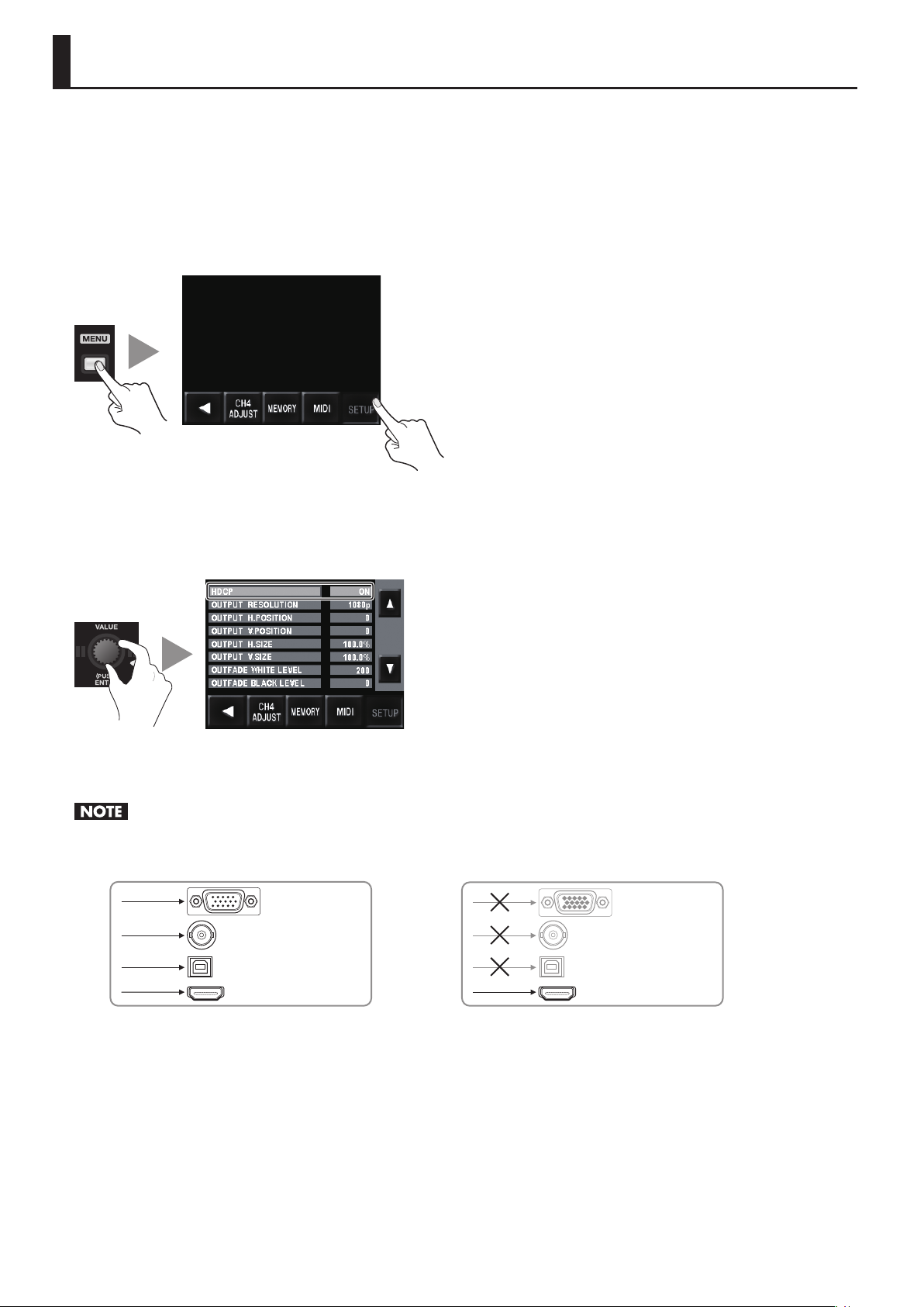
By default, the HDCP (High-bandwidth Digital Content Protection) setting of the V-4EX is turned o. This means that HDCPapplied signals from Blu-ray Disc players and the like cannot be input. When inputting signals to which HDCP is applied, follow the
procedure shown below to change the setting.
* HDCP is copyright-protection technology that prevents unlawful copying of content by encoding the path when sending digital signals from a
video playback device to a display monitor or other display equipment.
1. Display the SETUP menu.
Press the [MENU] button to display the menu. Use the touch panel to select [SETUP].
g.open-system-menu.eps
2. Change the setting.
Use the [VALUE] dial or the touch panel to select [HDCP]. Turn the [VALUE] dial to change the setting from [OFF] to [ON]. When the
conrmation screen appears, press the [VALUE] dial or use the touch panel to conrm the change.
g.HDCP-setting.eps
3. Exit the menu.
Press the [MENU] button several times to quit the menu.
When the setting change just described has been made, video output from the composite connector, the RGB/COMPONENT connector and the
USB port is stopped. Note, however, that HDCP-applied signals are output via the HDMI connector. Preview output also continues.
g.HDCP-signal-ow.eps
OF
RGB/COMPONENT
VIDEO
N
USB USB
HDMI
RGB/COMPONENT
VIDEO
HDMI
About the HDCP Indicator
The [HDCP] indicator on the top panel operates as described below.
• It lights up when an HDCP-compatible device is connected as the output device.
• It ashes when nothing is connected or when the connected device is not compatible with HDCP.
• It goes dark when [HDCP] is set to [OFF].
24
Page 25
Basic Operations
g.caution.eps
Using this unit makes it possible to create video transitions that occur at extremely high speeds. Depending on physical condition,
viewing such video might cause headache or discomfort. Never use this unit to create or present such video that might be
distressful to health. Roland assumes no responsibility in the event of any distress experienced by you or other viewers.
Switching the Monitor View Mode
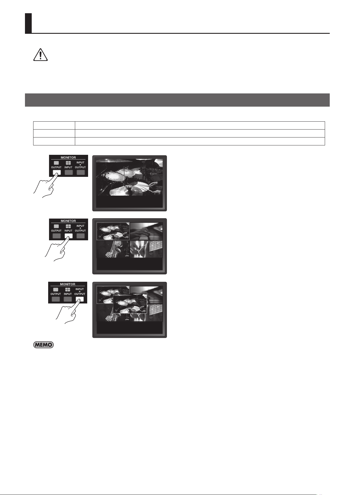
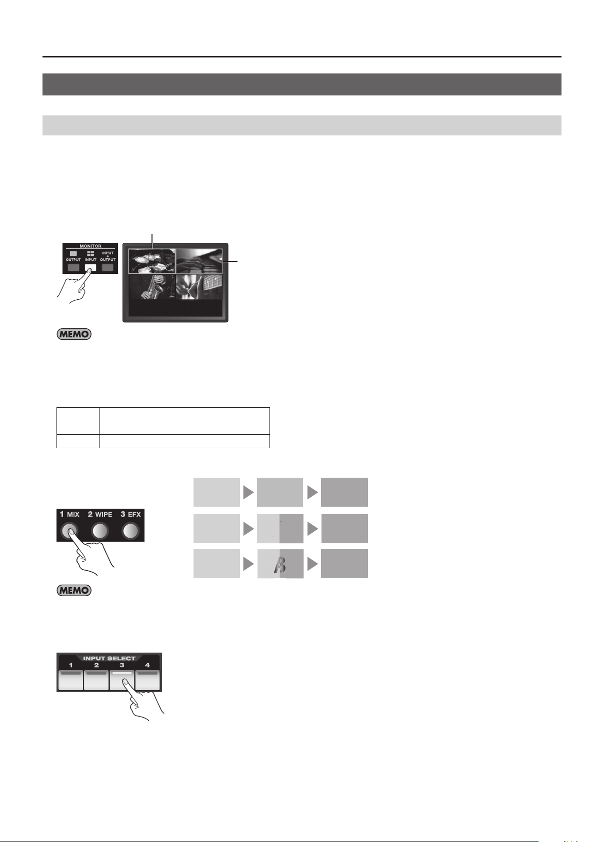
The V-4EX’s built-in monitor has the following three types of view modes. Use the MONITOR buttons to change the mode.
OUTPUT This displays the current video output from the V-4EX on a single screen.
INPUT This displays video input from source equipment on a four-way split screen.
INPUT + OUTPUT This displays the current video output by overlaying it on a four-way split screen displaying the input from source equipment.
g.monitor-mode.eps
You can select either 16:9 or 4:3 as the aspect ratio for video displayed on the monitor. Go to the SETUP menu (p. 44) and select [LCD PREVIEW ASPECT].
25
Page 26
Basic Operations
Changing Various Settings
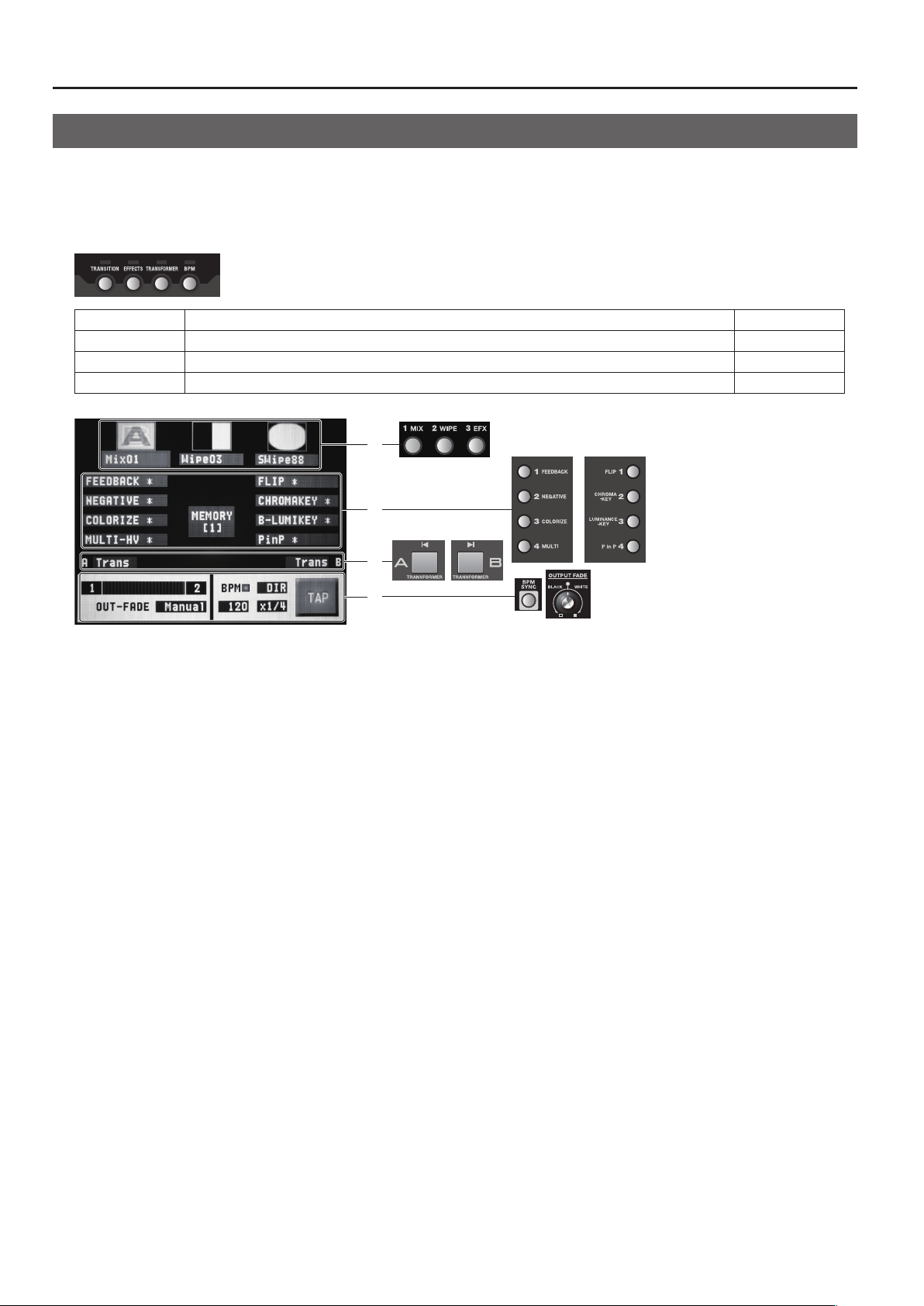
You can use the buttons under the built-in monitor to access various setup screens.
* The screen associated with the pressed button is displayed. The other areas of the monitor display the picture selected by the view mode.
* The setup screens are displayed overlaid on the picture on the monitor. You can hide the picture on the monitor by pressing the lighted
MONITOR button to make it go dark.
g.setup-buttons.eps
TRANSITION Press this to change transition eect settings. p. 27
EFFECTS Press this to change lter/composition eect settings. p. 32, p. 33
TRANSFORMER Press this to assign an eect to a Transformer button. p. 29
BPM Press this to change the automatic switching rhythm or to change the output fade mode. p. 29, p. 31
g.setup-screen.eps
1
2
3
4
1 Transition Eects
Pressing the [TRANSITION] button displays this area. From left to right, these correspond to the [1 MIX], [2 WIPE], and [3 EFX]
buttons.
Use the touch panel to choose the transition eect (1 through 3) whose settings you want to change, and turn the [VALUE] dial to
select the transition eects assigned to the respective buttons.
2 Filter/Compositing Eect
Pressing the [EFFECTS] button displays this area. The left side corresponds to Eect buttons 1 through 4 for A-Bus, and the right side
corresponds to Eect buttons 1 through 4 for B-Bus.
Use the touch panel to choose the Eect (A1 through A4 or B1 through B4) whose settings you want to change, and turn the
[VALUE] dial to select the lter/composition eects assigned to the respective buttons.
3 Transformer
Pressing the [TRANSFORMER] button displays this area. It corresponds to the A-Bus and B-Bus Transformers.
Use the touch panel to choose the bus (A or B) where you want to assign a transition eect, and turn the [VALUE] dial to select the
transition eect to assign.
4 BPM
Pressing the [BPM] button displays only this area.
For detailed information on BPM, refer to “Switching Automatically in Time with the Musical Rhythm” (p. 29).
This area displays the following information.
• Channel selected for A-Bus/B-Bus
• Position of the video fader
• Output fade mode
26
•
Page 27
Basic Operations
Red
StartFinish
A
A
Switching the Video
Switching the Picture Using the Video Fader
1. Check which channels are currently selected.
Before you carry out a transition operation, check which channels are currently selected. At powerup of the V-4EX, channel 1 is
selected for the A-Bus input selectors, and channel 2 is selected for the B-Bus input selectors. The bus corresponding to the end
to which the video fader has been moved is output, and when the built-in monitor is in the INPUT mode, a red border is displayed
around the output picture. A green border is displayed around the picture on the opposite bus (the standby video).
g.current-output.eps
Green
When the pictures on A and B are output simultaneously, such as during the application of a transition eect or a compositing eect, red borders
are displayed around both pictures.
2. Select a transition eect.
Use the transition eect buttons to select the transition eect you want to apply. By default, you can select from below.
1 MIX The pictures on A and B change gradually.
2 WIPE The pictures on A and B change using a wipe.
3 EFX The pictures on A and B change using a soft wipe.
g.transition-select.eps
MIX
WIPE
EFX
To assign other transition eects to 1 through 3, press the [TRANSITION] button to access the setup screen.
3. Select the channel on the opposite bus.
On the opposite bus, select the channel you want to output next. The indicator for the selected channel lights up green.
g.select-next-ch.eps
A AB
A
A B
A
A
B
B
Video sources blend together during
the switch process.
Video sources wipe from one to the other
during the switch process.
Video sources wipe (soft edge) from one to
the other during the switch process.
27
Page 28
Basic Operations
4. Switch between the A-Bus and the B-Bus.
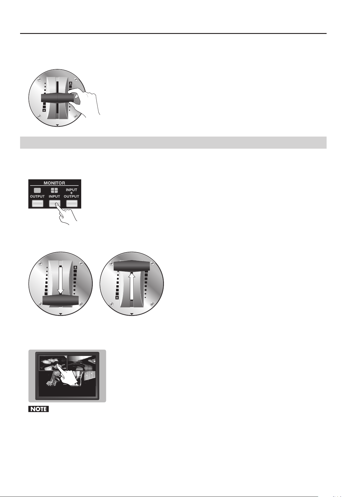
Move the video fader to the end for the bus of the channel you selected in step 3. The transition eect you selected in step 2 is
applied, and the output picture is switched.
g.move-fader.eps
Switching Using the Touch Panel
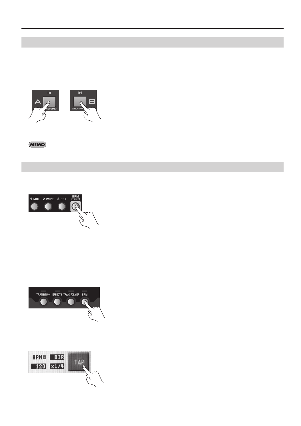
1. Change the monitor’s view mode to INPUT.
Press the MONITOR [INPUT] button to change the view mode to the INPUT mode. The display changes to a four-way split screen.
g.select-PVW-mode.eps
2. Select the bus.
Move the video fader all the way to the A-Bus end or the B-Bus end.
g.select-bus.eps
3. Use the touch panel to make the switch.
Touch the monitor to select the output picture. When you do this, a red border appears around the picture being output. The input
selector for the bus you selected in step 2 also lights up.
g.touch-select.eps
Note the following points when you switch video using the touch panel.
• Move the video fader all the way to the end of its stroke. The bus of one end is the target for switching. The touch panel cannot be used for
switching if the fader has not been moved all the way to one end.
• The touch panel cannot be used for switching while the menu screen is displayed. Exit the menu when you switch using the touch panel.
28
Page 29
Switching Using the Transformer Buttons
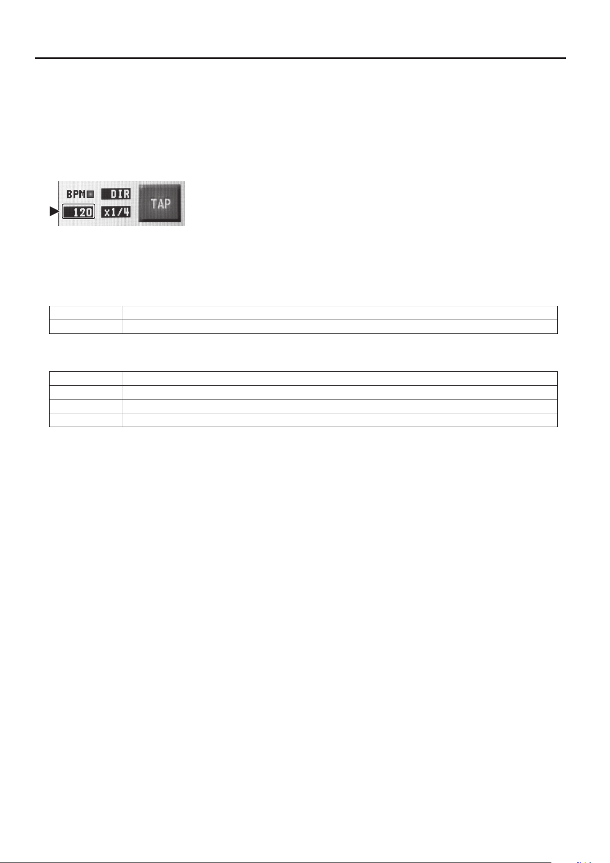
1. Select the channel on the opposite bus.
On the opposite, select the channel you want to output next. The indicator for the selected channel lights up.
2. Use the Transformer buttons to switch the picture.
Press the Transformer button for the bus of the channel selected in step 1. The output picture is switched using a cut.
g.transformer.eps
3. Return to the output on the original bus.
Releasing the Transformer button returns the output to the picture on the original bus.
To assign a transition eect to a Transformer button, press the [TRANSFORMER] button to access the setup screen.
Switching Automatically in Time with the Musical Rhythm
Basic Operations
Pressing the [BPM SYNC] button to make it light up causes automatic switching between A and B.
* Press the [BPM SYNC] button again and make it go dark to stop the automatic switching.
g.BMP-SYNC-button.eps
Use this feature when you want to perform switching on the rhythm of background music. By default, switching is performed at
120 BPM (beats per minute). You can use either of the following two methods to change the BPM setting.
Setting the BPM by Tapping
At times such as when the BPM value of the music is not known, set the BPM by tapping the screen with your nger.
1. Access the BPM setup screen.
Press the [BPM] button to access the BPM setup screen.
g.press-BPM-button.eps
2. Tap on the rhythm of the music.
Tap the on-screen [TAP] button on the rhythm of the background music. Tap several times to set the BPM value. The BPM indicator
starts to ash according to the BPM.
g.tap-BPM.eps
3. Exit the BPM setup screen.
Press the [BPM] button again to quit the setup screen.
29
Page 30
Basic Operations
Setting the BPM Numerically
If you know the BPM value of the music, you can set the numerical value directly.
1. Access the BPM setup screen.
Press the [BPM] button to access the BPM setup screen.
2. Change the value for BPM.
Select the BPM value area (set at “120” by default) to select it. Turn the [VALUE] dial to change the value.
g.BPM-value.eps
3. Exit the BPM setup screen.
Press the [BPM] button again to quit the setup screen.
About the Automatic Switching Mode
You can select either of the following two modes by selecting the area where [DIR] or [TRANS] is displayed and turning the [VALUE] dial.
DIR This means direct. The picture is switched using a cut.
TRANS This is the default setting and means transition. The picture is switched with the currently selected transition eect applied.
You can select the speed of automatic switching by selecting the area where numeric like [x1/4] or [x1/2] is displayed and turning
the [VALUE] dial.
x1/4 The picture is switched at quarter speed of the currently set BPM.
x1/2 This is the default setting. The picture is switched at half speed of the currently set BPM.
x1 The picture is switched at the same speed as the currently set BPM.
x2 The picture is switched at doubled speed of the currently set BPM.
30
Page 31
Basic Operations
Applying Fade to Final Output
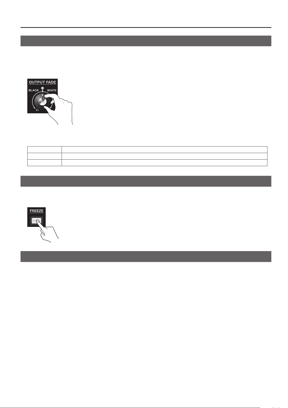
You can use the [OUTPUT FADE] dial to apply a fade to the V-4EX’s nal output. Applying a fade makes the output video gradually
disappear (fade-out) or appear (fade-in). Turning the dial counterclockwise applies a fade-out to black, and turning it clockwise
applies a fade-out to white. The indicator above the dial ashes while the fade is being applied. Returning the dial to its center
position makes the indicator light up continuously and returns the unit to 100% output.
g.fade-dial.eps
About the Output Fade Modes
You can select a mode from below by selecting the [OUT-FADE] area of BPM setting screen and turning the [VALUE] dial.
Manual This is the default setting. Apply a white or black fade by turning the dial.
Auto A fade-in/fade-out is repeated automatically. The speed varies according to the position of the dial.
No Ctrl Dial operation is disabled.
Freezing the Final Output
You can stop (freeze) the video being output. Pressing the [FREEZE] button freezes the picture being output and makes the button
light up. Press the button again to end the freezing.
g.freeze-button.eps
About AUTO SCAN Function
Press the [MENU] button and turn on [AUTO CHANNEL SCAN] in SETUP menu. The V-4EX switches channels 1 through 4
automatically. You can also set the following parameters.
• AUTO SCAN TIME You can set the interval of channel switching.
• AUTO TRANSITION TIME You can set the time of transition eect that is applied while switching.
* The V-4EX skips the channel where no video signal is input.
31
Page 32
Applying Filter Eects to Video
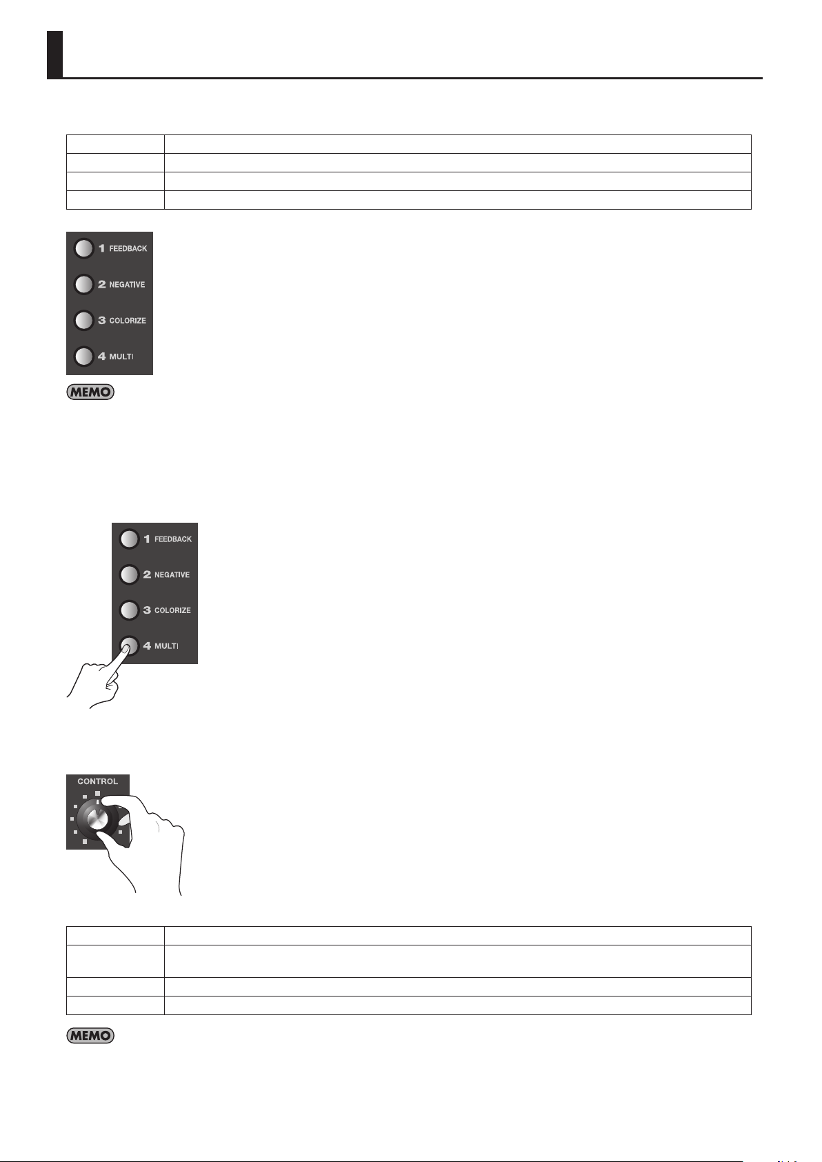
You can apply lter eects to the video on A-Bus by using the A-Bus Eect buttons. By default, the following lter eects are
assigned to 1 through 4.
FEEDBACK This repeats layering of the picture upon itself.
NEGATIVE This inverts the colors or brightness levels of the picture.
COLORIZE This eect adds color to the picture, producing a painting-like feel.
MULTI This splits the screen and reduces the size of the pictures.
g.A-bus-eects.eps
You can display a screen for assigning other eects by pressing the [EFFECTS] button.
1. Output the video to which you want to apply an eect.
Select and output the A-Bus channel you want to apply an eect.
2. Select the eect to apply.
Use the A-Bus Eect buttons to select the eect to apply.
g.select-lter-eect.eps
3. Adjust the amount of eect.
Turn the A-Bus Eect Control dial to adjust the amount of eect.
g.A-bus-control-dial.eps
The default lter eects change as follows when you turn the Eect Control dial.
FEEDBACK Turning the control clockwise shortens the repeating interval.
NEGATIVE
COLORIZE The colorization pattern varies according to the position of the dial.
MULTI Turning the dial clockwise increases the number of screen divisions.
By default, in addition to the four types of lter eects just described, [FLIP] is assigned to a B-Bus Eect button. When using this eect, select the
video on B-Bus. Pressing the B-Bus [FLIP] Eect button applies the ip eect. Also, to adjust the parameter of eect (or to change the direction of
screen ipping), use the B-Bus Eect Control dial.
Turning the dial clockwise cycles through these settings: brightness inversion -> color inversion -> brightness and color
inversion.
32
Page 33
Compositing Two Pictures
Use the compositing eects described below to composite (combine) two pictures. By default, these eects are assigned to B-Bus
Eect buttons 2 through 4.
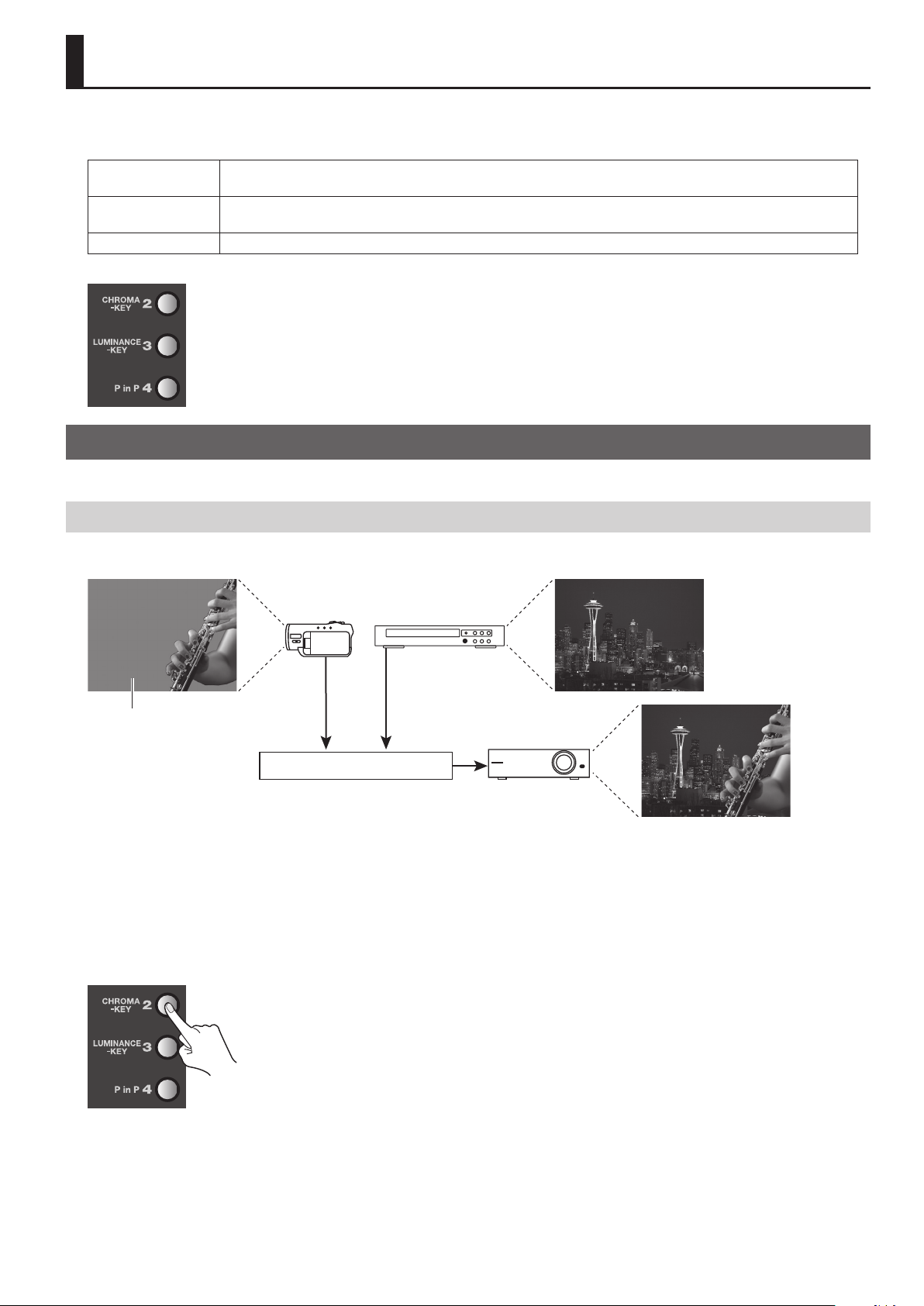
CHROMA-KEY
LUMINANCE-KEY
PinP (Picture-in-Picture) This reduces the size of the foreground picture and composites with the background picture as an inset screen.
g.composition-eects.eps
This extracts (blanks out) blue or green areas in the foreground picture and composites with the background picture.
By default, blue areas are extracted.
This extracts black or white areas of the foreground picture and composites with the background picture.
By default, black areas are extracted.
Key Compositing
You can use the KEY menu (p. 41) to change settings like the extraction color for chroma key or luminance key.
Compositing Using Chroma Key
Using chroma key, you can composite video that has a blue or green background. Blue is extracted by default..
g.chroma-key-image.eps
Blue (Green)
Chroma Key
1. Choose the background picture.
Use the A-Bus input selectors to select the channel of the background.
2. Select the video to display in the foreground.
Use the B-Bus input selectors to select the channel of the video to be displayed in foreground.
3. Perform compositing.
Press the B-Bus [CHROMA-KEY] Eect button to make it light up.
g.press-chroma-key.eps
33
Page 34
Compositing Two Pictures
4. Adjust the amount of keying.
Turn the B-Bus Eect Control dial to adjust the amount of keying.
g.adjust-key-level.eps
5. Adjust the level of the foreground video.
You can adjust the display level of the foreground video by moving the video fader forward or backward. Moving it all the way to
the B-Bus end displays the foreground video at a level of 100%. Moving it all the way to the A-Bus end makes the foreground video
disappear.
Compositing Using Luminance Key
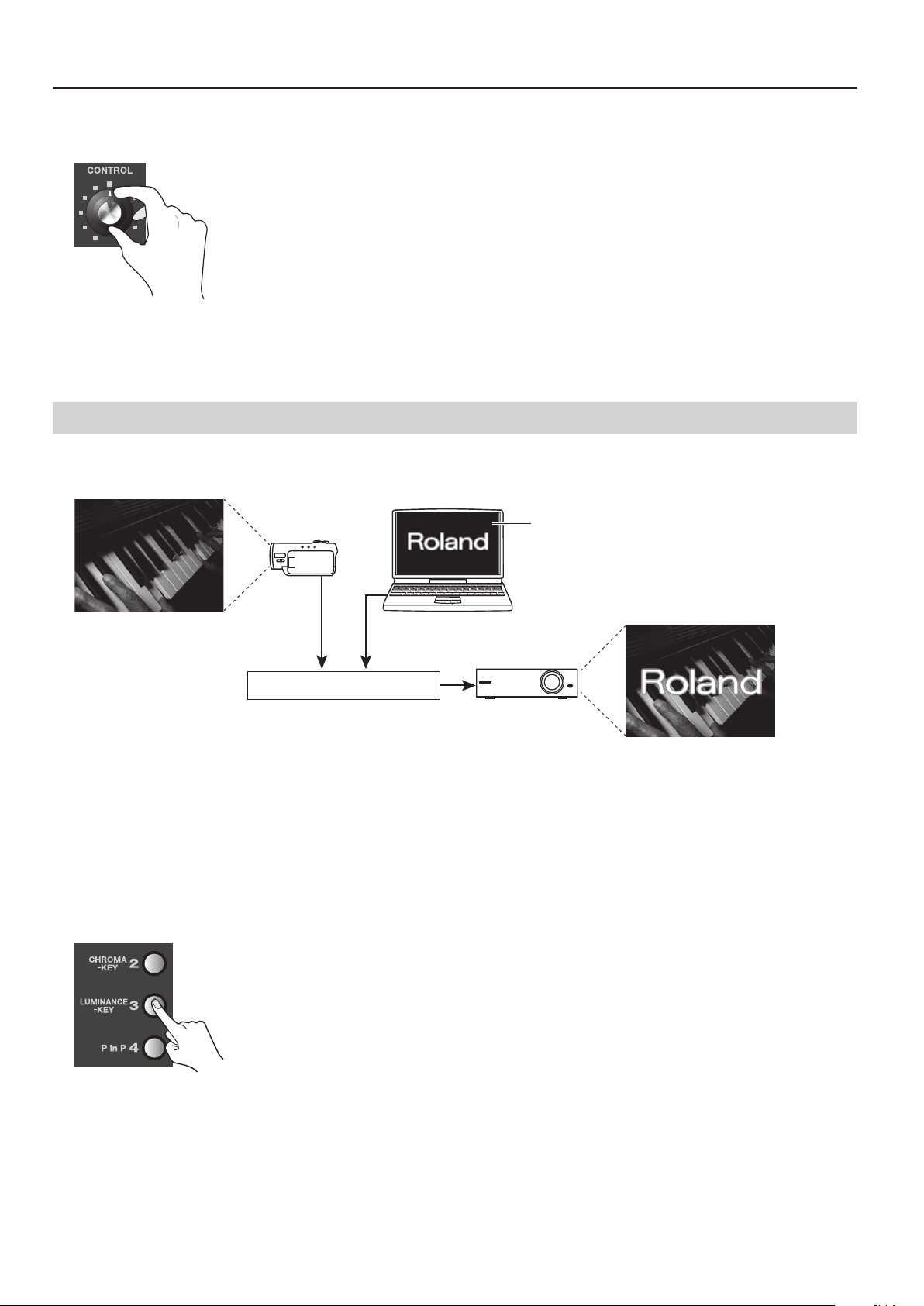
Using luminance key, you can superimpose logos or text on a background picture. You can connect RGB output from a computer to
INPUT 4 and composite with video. By default, black is extracted.
g.luminance-key-image.eps
Black (White)
Luminance Key
1. Choose the background picture.
Use the A-Bus input selectors to select the channel of the background.
2. Select the video to display in the foreground.
Use the B-Bus input selectors to select the channel to be displayed in the foreground. To composite a logo or text input from a
computer, select [4].
* Enable the input connector where the computer is connected.
3. Perform compositing.
Press the B-Bus [LUMINANCE-KEY] Eect button to make it light up.
g.press-luminance-key.eps
4. Adjust the amount of keying.
Turn the B-Bus Eect Control dial to adjust the amount of keying.
5. Adjust the level of the foreground video.
You can adjust the display level of the logo or text by moving the video fader forward or backward. Moving it all the way to the
B-Bus end displays the logo or text at a level of 100%. Moving it all the way to the A-Bus end makes the logo or text disappear.
34
Page 35
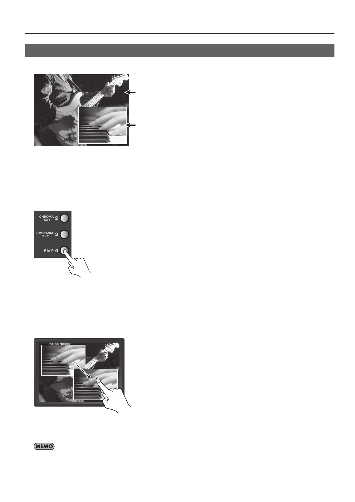
Compositing Using Picture-in-Picture
Compositing that overlays an inset screen on a background is called “Picture-in-Picture” (PinP).
g.PinP-image.eps
Background
Inset Screen
1. Choose the background picture.
Use the A-Bus input selectors to select the channel of the background.
2. Select the video to display as the inset screen.
Use the B-Bus input selectors to select the channel to be displayed as the inset screen.
3. Perform compositing.
Press the B-Bus [P in P] Eect button to make it light up.
g.press-PinP.eps
Compositing Two Pictures
4. Change the size of the inset screen.
Turn the B-Bus Eect Control dial to change the size of the inset screen.
* Turning the dial sequentially recalls the PinP 1 through 8 settings.
5. Change the position of the inset screen.
Press the [OUTPUT] MONITOR button to display the composited results on the built-in monitor. You can change the position of the
inset screen by sliding your nger on the touch panel.
g.adjust-inset-position.eps
6. Adjust the display level of the inset screen.
You can adjust the display level of the inset screen by moving the video fader forward or backward. Moving it all the way to the
B-Bus end displays the inset screen at a level of 100%. Moving it all the way to the A-Bus end makes the inset screen disappear.
You can also use the PinP menu (p. 42) to make settings for the position and size of the inset screen. You can save up to eight sets of settings at
the PinP menu (EFFECTS 140 through 147). To save settings, press the [MENU] button to display the menu, then press the on-screen [PinP 1 - 4] or
[PinP 5 - 8] button. Selecting [SAVE CURRENT PinP] lets you save the current settings to the corresponding number.
35
Page 36
About Other Features
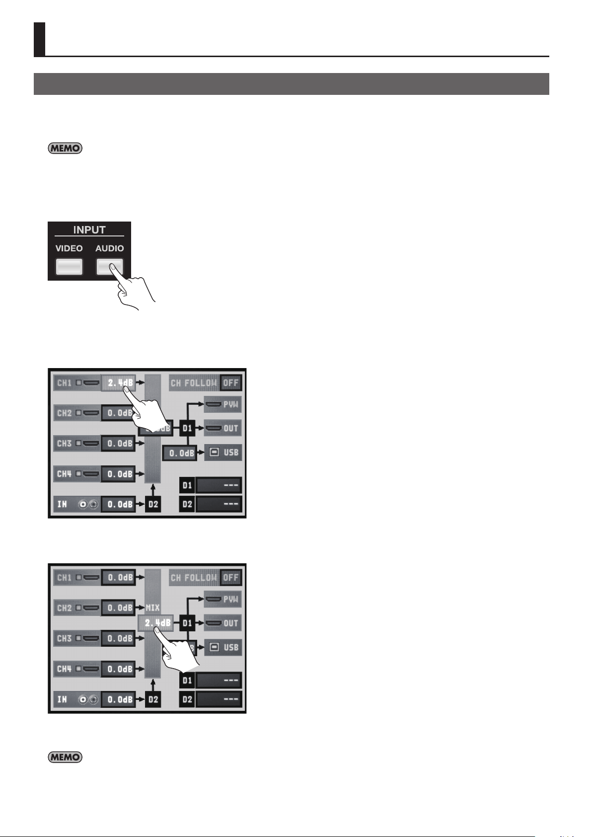
Adjusting the Audio Balance/Volume
On the V-4EX, you can output video and audio together (embedded audio) from the HDMI connector and the USB port. Using the
procedure in this chapter, you can adjust the balance of analog audio (1 stereo) input via the AUDIO IN connectors and audio (4
stereo) input via HDMI. After that, you can also adjust the output volume.
The results of balance/volume adjustment are applied to the audio output via HDMI and USB. Carry out balance/volume adjustment while
monitoring the sound via connected monitor speakers or the computer’s speakers.
1. Display the audio setup screen.
Press the [AUDIO] button in the INPUT section to display the setup screen for audio.
g.audio-setup-button.eps
2. Adjust the balance for each channel.
Use the touch panel to select from among [CH 1] to [CH 4] or [IN], then turn the [VALUE] dial to raise or lower the level.
* [CH 1] through [CH 4] correspond to HDMI inputs 1 through 4. [IN] corresponds to analog input.
g.adjust-ch-level.eps
3. Adjust the volume of the nal output.
Use the touch panel to select [MIX], then turn the [VALUE] dial to raise or lower the level.
g.adjust-out-level.eps
4. Close the setup screen.
Press the [AUDIO] button in the INPUT section again to return to the original screen.
You can mute/unmute the sound by holding down the [AUDIO] button in INPUT section and press an input selector. The A-Bus input selectors
(1 through 4) correspond to channels 1 through 4. B-Bus input selectors [1] corresponds to AUDIO IN. B-Bus input selector [4] corresponds to the
output. Each press mutes/unmutes the sound of the corresponding channel. The output switches between mute and the currently set output level.
36
Page 37
Aligning the Timing of Video and Audio (Lip-sync)
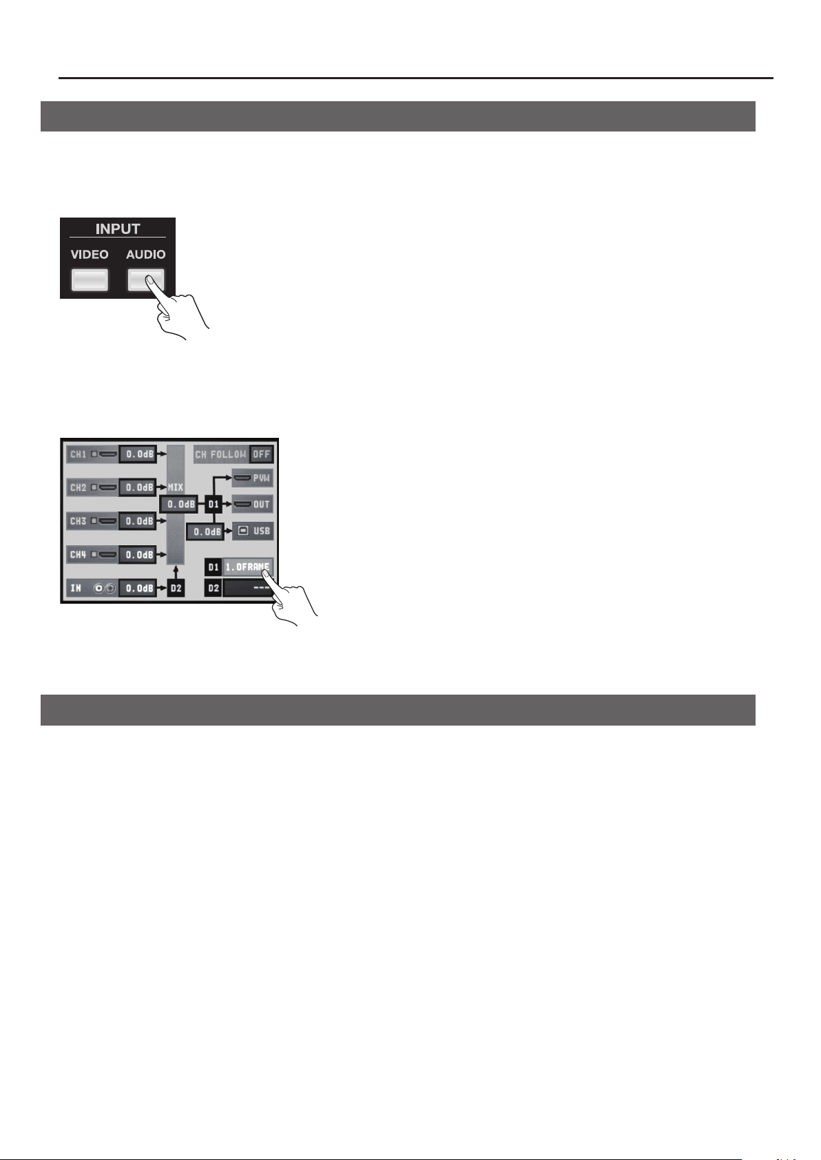
You can use the procedure described below to apply delay to audio and align the video/audio timing.
1. Display the audio setup screen.
Press the [AUDIO] button in the INPUT section to display the setup screen for audio.
g.audio-setup-button.eps
2. Adjust the amount of delay.
Use the touch panel to select [D1] or [D2], then operate the [VALUE] dial to adjust the amount of delay.
* [D1] is delay applied globally to the output, and [D2] is delay applied only to AUDIO IN input.
* You can set [D1] in a range of 0.0 to 4.0 frames and [D2] in a range of 0.0 to 2.0 frames.
g.adjust-delay.eps
About Other Features
3. Close the setup screen.
Press the [AUDIO] button in the INPUT section to return to the original screen.
About AUDIO FOLLOW Function
The V-4EX automatically increases the level of same audio channel when you switch video channel (1-4) if the [CH FOLLOW] is
turned on. In this case, the audio outputs of other channels are muted.
* AUDIO IN level can follow switching video channel 4.
37
Page 38
About Other Features
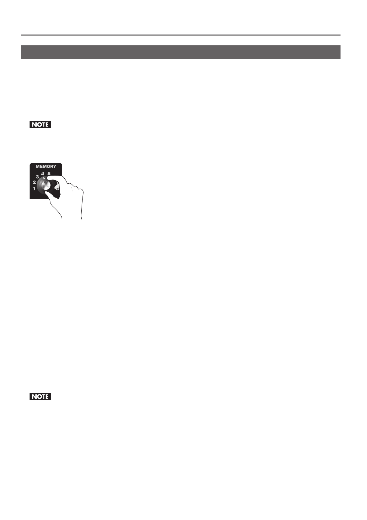
Saving Settings
The MEMORY dial on the V-4EX has positions from [1] to [8]. You can save the button and dial settings described below to [2]
through [8].
• Eects assigned to A-Bus and B-Bus Eect buttons
• Settings of the A-Bus and B-Bus TRANSFORMER buttons
• Eects assigned to transition buttons (MIX/WIPE/EFX)
• The BPM SYNC setting
• The setting of the OUT FADE dial
When [1] has been selected, settings can be changed, but not saved.
1. Select the number to save to.
Turn the MEMORY dial to select a number from [2] to [8] as the destination for saving.
g.turn-memory-dial.eps
2. Change the setting.
Refer to “Menu Operations and Menu List” (p. 40) to change the settings for the buttons and dials. When you close the menu
screen, they are saved at the number you selected in step 1.
3. Return the unit to its factory-default state.
Turning the MEMORY dial to [1] returns the unit to its factory-default state.
Copying/Exchanging/Protecting Settings
You can take settings saved at a number from [2] to [7] and copy them to a dierent number or exchange (swap) them with the
values saved at another number. You can also protect the values saved at a specic number.
* Before carrying out this operation, turn the MEMORY dial to access the number whose settings you want to copy, exchange, or protect.
Copy
Press the [MENU] button and use the MEMORY menu (p. 43) to select [COPY]. Turn the [VALUE] dial to select the copy-destination
number, then press the [VALUE] dial to execute the copy operation.
* Selecting [ALL] as the copy destination copies the current settings at all numbers except [1].
Exchange
Press the [MENU] button and use the MEMORY menu to select [EXCHANGE]. Turn the [VALUE] dial to select the exchangedestination number, then press the [VALUE] dial to execute the exchange.
Protect
Press the [MENU] button and use the MEMORY menu to select [PROTECT]. When this is set to [ON], settings cannot be rewritten.
MEMORY [1] cannot be selected for copying, exchange.
38
Page 39
About Other Features
Curve-C
Making the Settings for Video Fader Operation
Operation Mode of the Video Fader
When video is switched using the Transformers or [BPM SYNC], situations might occur in which the position of the video fader
does not match the actual output. Selecting [QUICK] as the operation mode lets you make the actual output match the position of
the video fader instantly when you move the fader. Note, however, that when [QUICK] has been selected, the output video might
change suddenly. To avoid such sudden changes, use the unit with the [NORMAL] setting.
• NORMAL This is the default setting. The picture does not change until the position of the video fader matches the actual output.
• QUICK The actual output immediately changes to match the video fader position the instant you move the fader.
To change the operation mode for the video fader, go to the SETUP menu (p. 44) and change the setting for [FADER MODE].
Video Fader Operating Curve
You can select one from three types of operating curves below.
• Curve A This is the default setting. The entire stroke of the video fader is used to perform A/B switching.
• Curve B Response is more sensitive at the center of the stroke. Response at either end is less sensitive.
• Curve C Only the center of the stroke is eective. The ends are completely unresponsive.
g.fader-curve.eps
Output
B-Bus
Curve-A
Curve-B
A-Bus
A
To change the operating curve of the video fader, go to the SETUP menu (p. 44) and change the setting for [FADER CURVE].
Video Fader
B
39
Page 40
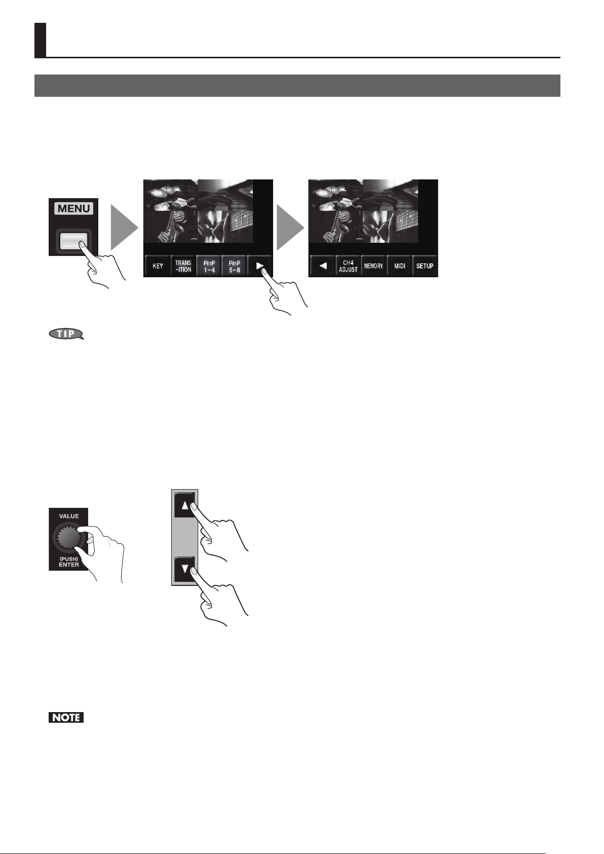
Menu Operations and Menu List
Menu Operations
Use the [MENU] button and the [VALUE] dial, or the touch panel on the built-in monitor, to make various settings.
1. Access the menu.
Display the menu screen on the built-in monitor by pressing the [MENU] button. Displayed rst is the top menu. From here, you can
access the setup screens for various items.
g.open-menu.eps
When all MONITOR buttons (OUTPUT, INPUT, and INPUT + OUTPUT) are dark, input and output video is hidden and only the menus are displayed.
When you want to display only the menus and hide the video, press the currently lighted button to make it go dark.
2. Select the item to set.
Select the item to set by turning and pressing the [VALUE] dial or by using the touch panel on the built-in monitor. A list of the
items is displayed. If you do not nd the item you want to set on the rst page, you can use the left and right cursor buttons or the
[VALUE] dial to scroll the displayed pages.
3. Select a parameter.
Select a parameter by turning and pressing the [VALUE] dial or by using the touch panel on the built-in monitor. If the parameter
cannot be displayed on just one page, you can use the [VALUE] dial or the up and down buttons to scroll through them.
g.parameter-up-down.eps
or
4. Change and apply the setting value.
Change the setting value by turning the [VALUE] dial, then apply the value by pressing the dial.
5. Go back to the original screen.
Press the [MENU] button several times to go back to the original screen.
The settings of the menu items are saved to the internal memory when the menu disappears and you return to the original screen. Turning o the
power while the menu is displayed causes any settings that have been made to be lost.
40
Page 41
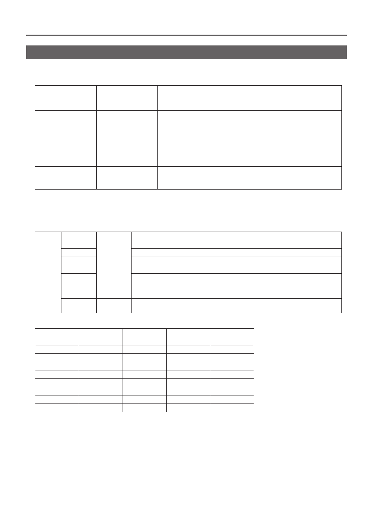
Menu Operations and Menu List
Menu List
* Display setting values shown enclosed in square brackets (“[ ]”) are factory-default values.
KEY Menu
WHITE LUMI KEY LEVEL 0 - [128] - 255 This species the degree of white-key extraction.
WHITE LUMI KEY EDGE 1 - [14] - 15 This species the degree of edge blur for white-key extraction.
BLACK LUMI KEY LEVEL 0 - [128] - 255 This species the degree of black-key extraction.
BLACK LUMI KEY EDGE 1 - [14] - 15 This species the degree of edge blur for black-key extraction.
BLUE-MGNT, [BLUE-CYAN],
RED-MGNT, RED-YELW,
CHROMA KEY COLOR
CHROMA KEY LEVEL 0 - [128] - 255 This species the degree of extraction for chroma key.
CHROMA KEY EDGE 1 - [14] - 15 This species the degree of edge blur for chroma key.
SILHOUETTE LEVEL 0 - [128] - 255
TRANSITION Menu
This species a user transition (p. 41). You can assign individual transition eects to positions 1 through 8 of the video fader. Making
this setting lets you use multiple transition eects in combination.
* The values of 001 through 227 correspond to the transition eect numbers.
POSITION 1
POSITION 2 This species the eect assigned to position 2.
POSITION 3 This species the eect assigned to position 3.
POSITION 4 This species the eect assigned to position 4.
USER 1 -- 4
POSITION 5 This species the eect assigned to position 5.
POSITION 6 This species the eect assigned to position 6.
POSITION 7 This species the sound assigned to position 7.
POSITION 8 This species the eect assigned to position 8 (B-Bus end).
SWITCHING
MGNT-RED, MGNT-BLUE,
CYAN-GREN, GREN-CYAN,
GREN-RED, CYAN-BLUE,
YELW-GREN, YELW-RED
this species the eect assigned to position 1 (A-Bus end).
001 - 227
* Except 204
-- 207
OFF, BPMx1,
BPMx2, BPMx4
This turns on/o the automatic switching feature for synchronization in time with the BPM.
This species the extraction color for chroma key.
When you are using Silhouette (Eect No. 052 -- 060), this species the threshold value
of the area between the light and dark areas of the picture.
The default assignments to POSITION 1 -- 8 are as follows.
USER 1 USER 2 USER 3 USER 4
POSITION 1 099 : Wipe94 010 : Wipe05 054 : Wipe49 092 : Wipe87
POSITION 2 096 : Wipe91 011 : Wipe06 060 : Wipe55 081 : Wipe76
POSITION 3 094 : Wipe89 014 : Wipe09 057 : Wipe52 104 : Wipe99
POSITION 4 093 : Wipe88 015 : Wipe10 058 : Wipe53 049 : Wipe44
POSITION 5 094 : Wipe90 017 : Wipe12 054 : Wipe49 029 : Wipe24
POSITION 6 097 : Wipe92 018 : Wipe13 060 : Wipe55 073 : Wipe68
POSITION 7 098 : Wipe93 019 : Wipe14 057 : Wipe52 029 : Wipe24
POSITION 8 099 : Wipe94 021 : Wipe16 058 : Wipe53 092 : Wipe87
SWITCHING O O BPMx2 O
41
Page 42
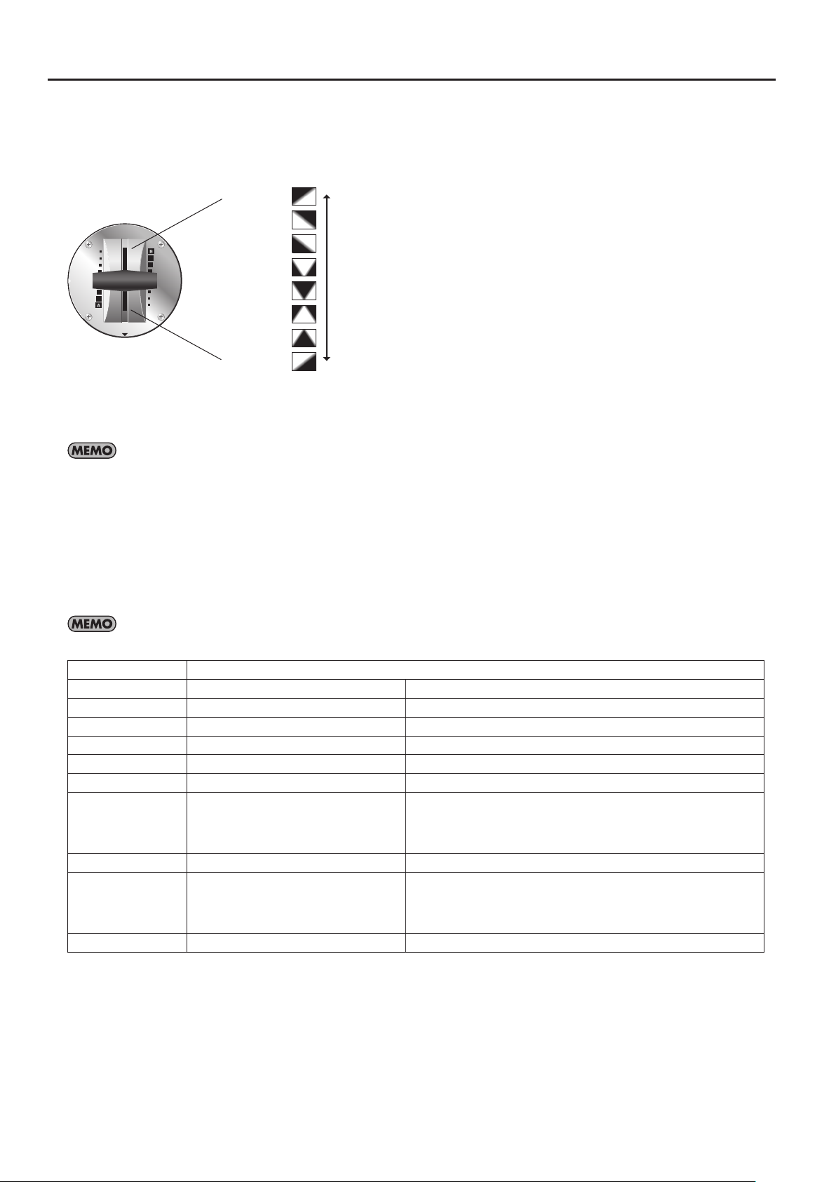
Menu Operations and Menu List
Example
User-set Transition Eects (User Transition)
Using the user transition feature lets you assign eight transition eects to the video fader. As the following gure shows, transition
eects are assigned to eight equally spaced positions along the stroke of the video fader.
g.eight-transitions.eps
POSITION 8 =
POSITION 7 =
POSITION 6 =
POSITION 5 =
POSITION 4 =
POSITION 3 =
POSITION 2 =
POSITION 1 =
Use the following procedure to make assignments.
• From the TRANSITION menu, select a user-setting number (USER 1 -- USER 4).
• Select the position to assign the transition eect (POSITION 1 -- POSITION 8).
You can also perform automatic switching at the tempo set using BPM as you apply a transition eect set to POSITION 1 through 8. Go to the
TRANSITION menu and select [SWITCHING], then select the setting from among the following. Selecting OFF results in no automatic switching.
• BPMx1 Automatic switching is performed at the tempo set using BPM.
• BPMx2 Automatic switching is performed at double the BPM tempo.
• BPMx4 Automatic switching is performed at four times the BPM tempo.
PinP Menu
Use the [PinP 1-4] button or [PinP 5-8] button to access the setup menu. Select a value from 1 to 8, then make the settings for the
following items.
PinP 1 -- 8 correspond to eect numbers 140 -- 147. You can access the settings for PinP 1 -- 8 by pressing the [EFFECTS] button.
SAVE CURRENT PinP This saves the current PinP settings.
H.POSITION 0 - 705 This species the position of the inset screen in the horizontal direction.
V.POSITION 0 - 239 This species the position of the inset screen in the vertical direction.
HV.SIZE 1 - 220 This adjusts the size of the inset screen at a xed aspect ratio.
H.SIZE 1 - 220 This adjusts the horizontal size of the inset screen.
V.SIZE 1 - 220 This adjusts the vertical size of the inset screen.
BORDER 0 - 15 This adjusts the border width for the inset screen.
BLACK, WHITE, GRAY, RED, GREEN, BLUE,
BORDER COLOR
SHADOW 0 - 15 This species the length of the shadow added to the inset screen.
SHADOW COLOR
TRIMMING 0 - 30 This species the trimming width for the inset screen.
YELLOW, CYAN, MAGENTA, ORANGE,
GREN-CYAN, BLUE-MGNT, YELW-GREN,
BLUE-CYAN, PINK
BLACK, WHITE, GRAY, RED, GREEN, BLUE,
YELLOW, CYAN, MAGENTA, ORANGE,
GREN-CYAN, BLUE-MGNT, YELW-GREN,
BLUE-CYAN, PINK
This species the border color for the inset screen.
This species the color of the shadow added to the inset screen.
42
Page 43
CH 4 ADJUST Menu
You can set the following items for input on channel 4 only.
However, it’s not possible to adjust values below for composite input of CH 4.
H.POSITION -200 - [0] - 500 This adjusts the display position in the horizontal direction.
V.POSITION -200 - [0] - 500 This adjusts the display position in the vertical direction.
H.SIZE [100.0%] - 150.0% This adjusts the size in the horizontal direction.
V.SIZE [100.0%] - 150.0% This adjusts the size in the vertical direction.
CONTRAST 0 - [64] - 127 This adjusts the contrast.
BRIGHTNESS 0 - [64] - 127 This adjusts the brightness.
SHARPNESS [0] - 127 This adjusts the sharpness of outlines.
FLICK FILTER 0 - [7] - 10
COLOR 0 - [64] - 127 This adjusts the color.
[AUTO], 480/576i, 480/576p,
720p, 1080i, 1080p, 640x480,
INPUT RESOLUTION
800x600, 1024x768, 1280x768,
1280x1024, 1366x768,
1400x1050, 1600x1200,
1920x1200
This adjusts the degree of icker reduction. The icker lter works to blur or equalize the
brightness dierences between scanning lines.
This sets the input resolution. This setting is eective when the input setting for channel 4 is
HDMI or RGB/COMPONENT.
Menu Operations and Menu List
* The valid setting range of H.POSITION and V.POSITION diers depending of the input resolution. In the invalid range, changing of the value does
not alter the image position.
MEMORY Menu
COPY MEMORY Current No. ->[2] - 8 This copies the data at the current memory number to a dierent number.
EXCHANGE
MEMORY
MEMORY PROTECT [OFF], ON This protects the data at the current memory number.
Current No. <->[2] - 8 This exchanges the data at the current memory number with the data at another number.
MIDI Menu
For information about operating the unit by remote control using MIDI, download “Remote Control Guide” from the following
Roland website.
http://www.rolandsystemsgroup.net/
43
Page 44

Menu Operations and Menu List
SETUP Menu
HDCP [OFF], ON This turns HDCP on/o.
[AUTO], 480/576i,
480/576p, 720p, 1080i,
1080p, 640x480, 800x600,
OUTPUT RESOLUTION
OUTPUT H.POSITION -200 - [0] - 500 This adjusts the output position in the horizontal direction.
OUTPUT V.POSITION -200 - [0] - 500 This adjusts the output position in the vertical direction.
OUTPUT H.SIZE 50.0% - [100.0%] - 150.0% This adjusts the output size in the horizontal direction.
OUTPUT V.SIZE 50.0% - [100.0%] - 150.0% This adjusts the output size in the vertical direction.
OUTPUT CONTRAST 0 - [64] - 127 This adjusts the output contrast.
OUTPUT BRIGHTNESS 0 - [64] - 127 This adjusts the output brightness.
OUTPUT COLOR 0 - [64] - 127 This adjusts the output color.
OUTPUT COLOR SPACE
OUTPUT DVI-D/HDMI [AUTO], DVI-D, HDMI This sets the output mode of the HDMI connector.
OUTFADE WHITE LEVEL 0 - [255] This sets the white level during output fade.
OUTFADE BLACK LEVEL [0] - 255 This sets the black level during output fade.
AUTO CHANNEL SCAN [OFF], ON This turns on/o the auto swtiching of CH1 through CH4.
AUTO SCAN TIME 1 - [5] - 120 sec This sets the interval of auto switching.
AUTO TRANSITION TIME 0.0 - [0.5] - 4.0 sec This sets the time of transition eect that is applied for auto switching.
AUDIO IN-CH4 FOLLOW [OFF], ON When [ON] is selected, the level of AUDIO IN is increased when you switch video channel 4.
NAM/FAM CROSS
POINT
FADER MODE [NORMAL], QUICK This selects the operation mode of the video fader.
FADER CURVE
FADER CALIBRATE A This performs calibration of the video fader at the A-Bus end.
FADER CALIBRATE B This performs calibration of the video fader at the B-Bus end.
LCD PREVIEW ASPECT [16:9], 4:3 This selects the aspect ratio of monitor display.
LCD BRIGHTNESS LOW, [HIGH] This sets the brightness of the monitor.
MENU DISPLAY LEVEL 5 - [13] - 15 This adjusts the appearance level of menu display.
BCKGND LEV - OVERLAY 1 - [12] This adjusts the brightness of the background (four-way split screen) in overlay display.
NO SIGNAL BACK [BLACK], BLUE This selects the background color at times of no input.
COLOR BAR OUTPUT [OFF], ON This selects whether a color bar is output.
AUTO OFF OFF, [ON]
USB STREAMING [OUTPUT], MONITOR This selects the output from the USB port.
NTSC/PAL NTSC, PAL This switches between NTSC and PAL.
FACTORY RESET This returns the unit to its factory defaults.
1024x768, 1280x768,
1280x1024, 1366x768,
1400x1050, 1600x1200.,
1920x1200
[AUTO], RGB-FULL,
RGB-LIMIT, YCbCr
0 - [50] - 100 This sets the point during NAM/FAM transition (p. 46).
[CURVE-A],
CURVE-B, CURVE-C
This species the output resolution.
This sets the output color space.
This selects the operating curve of the video fader.
This makes the setting for AUTO OFF. When [ON] is selected, power is turned o
automatically (p. 10).
* The valid setting range of OUTPUT H.POSITION and OUTPUT V.POSITION diers depending of the output resolution. In the invalid range,
changing of the value does not alter the image position.
44
Page 45
Appendices
Main Specications
Signal Processing
Video 4:2:2 (Y/Pb/Pr), 8 bits (Internal Processing : 480/59.94p when set to NTSC, 576/50p when set to PAL)
Audio Sampling Rate : 24 bits/48 kHz, 2 ch
Input/Output Formats
Refer to “About Input/Output Formats” (p. 23).
Input/Output Connectors
HDMI Type A (19 pins) x 4 (INPUT 1 -- 4)
Input
Output
Video
Audio RCA pin type x 1 pair (AUDIO IN)
Final Output
Preview Output HDMI Type A (19 pins) x 1 (PVW OUT)
RGB/Component
Composite BNC Type x 4 (INPUT 1 -- 4)
S-Video 4-pin mini DIN type x 1 (INPUT 4)
HDMI Type A (19 pins) x 1 (OUTPUT)
RGB/Component HD DB-15 type x 1 (OUTPUT)
Composite BNC type x 1 (OUTPUT)
HD DB-15 type x 1 (INPUT 4)
Other Connectors
MIDI 5 pins DIN type x 2 (IN, OUT/THRU)
USB B type x 1 (for streaming and remote control)
Signal Level/Impedance
RGB/Component
Composite
S-Video
Analog Audio
Signal Level 1.0 Vp-p (luminance), 0.7 Vp-p (chroma)
Impedance 75 ohms
Signal Level 1.0 Vp-p
Impedance 75 ohms
Signal Level 1.0 Vp-p
Impedance 75 ohms
Nominal Input Level - 10 dBu
Maximum Input Level + 8 dBu
Impedance 15 k ohms
Video Eects
Transition Mix, Cut, Wipe (259 patterns)
Composition/Filter Picture in Picture, Luminance Key, Chroma Key, Strobe, Negative, Colorize, Feedback, Emboss, Multi, Mirror etc. (148 types)
Others Output Fade, Freeze
Others
Display Graphic Color LCD, 320 x 240 dots, touch panel
Power Supply AC adaptor (DC 9 V)
Current Draw 2.0 A
Dimensions
Weight
(excl. AC adaptor)
Accessories AC adaptor, Power Cord, RCA - BNC conversion plug x 2, Owner’s Manual
225 (W) x 296 (D) x 105 (H) mm
8-7/8 (W) x 11-11/16 (D) x 4-3/16 (H) inches
2.6 kg
5 lbs 12 oz
* 0 dBu = 0.775 Vrms
* In the interest of product improvement, the specications and/or appearance of this unit are subject to change without prior notice.
45
Page 46
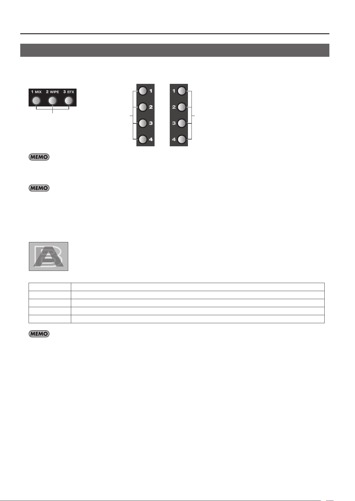
Appendices
Eects List
You can assign transition eects to the MIX, WIPE, and EFX buttons. You can also allocate lter eects and compositing eects to
the A-A-Busnd B-Bus Eect buttons.
g.eect-assign.eps
Transition Eects
If an eect has an “*” (asterisk) after its name, you can change its setting value in a smooth, continuous manner by turning the Eect Control dial.
Pressing a button to which such an eect is assigned makes the button ash. If no eect indicated by an “*” is assigned to the button, the button
lights up steadily when pressed. In such cases, operation of the Eect Control dial has no eect.
When multiple controllable eects are assigned to these buttons, you can control the eect of last pressed button using the dial. In such case, the
last pressed button ashes and previously pressed button(s) lights up steadily.
Filter/Composition
Eects
Filter/Composition
Eects
Transition Eects
Mix
g.MIX.eps
001 : Mix01 The A and B video is switched gradually.
002 : Fam01 This is an abbreviation of “full additive mix.” The A and B luminance levels are maintained during the transition.
003 : Fam* You can move the A/B cross point during FAM transition.
004 : Nam01 This is an abbreviation of “non-additive mix.” Display during transition starts with areas of high luminance.
005 : Nam* You can move the A/B cross point during NAM transition.
You can set the cross point (0% to 100%) by going to the SETUP menu (p. 44) and setting [NAM/FAM CROSS POINT].
46
Page 47
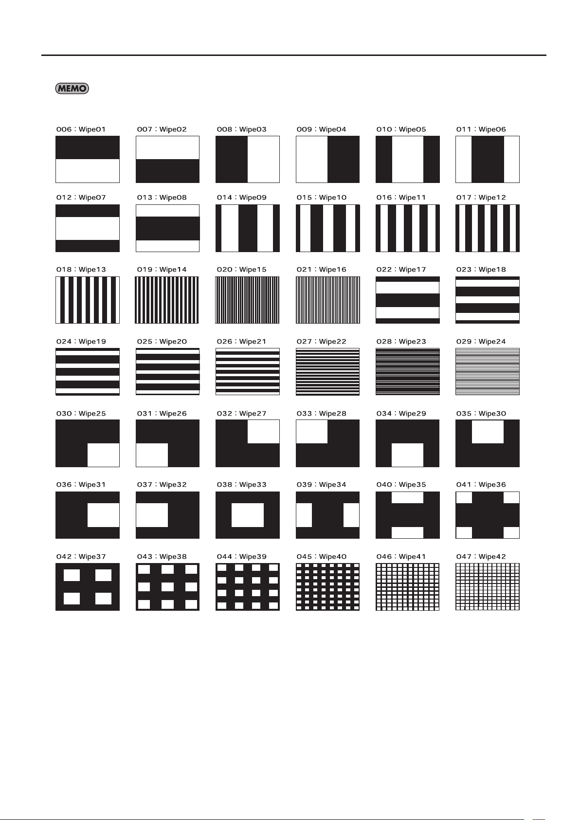
Appendices
Wipe
In the following wipe illustrations, black areas represent the picture after the transition (the picture that appears), and white areas represent the
picture before the transition (the picture that disappears).
47
Page 48
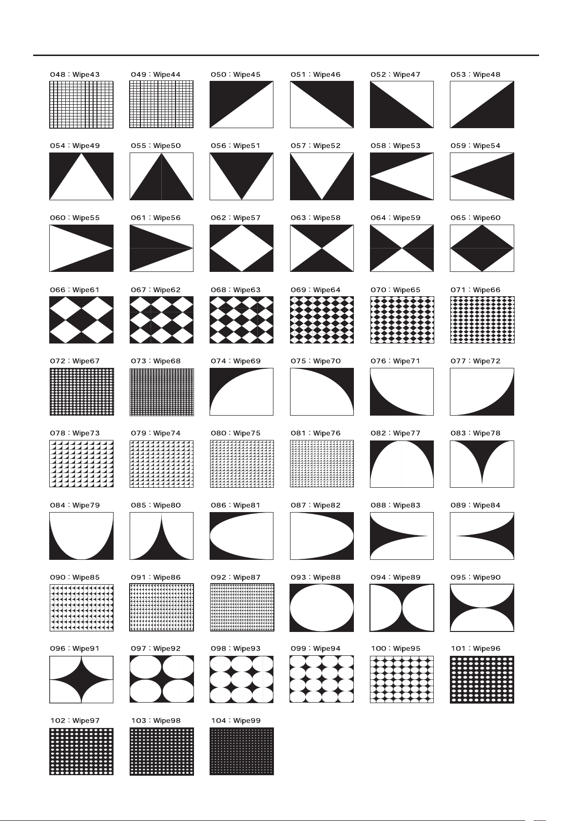
Appendices
48
Page 49
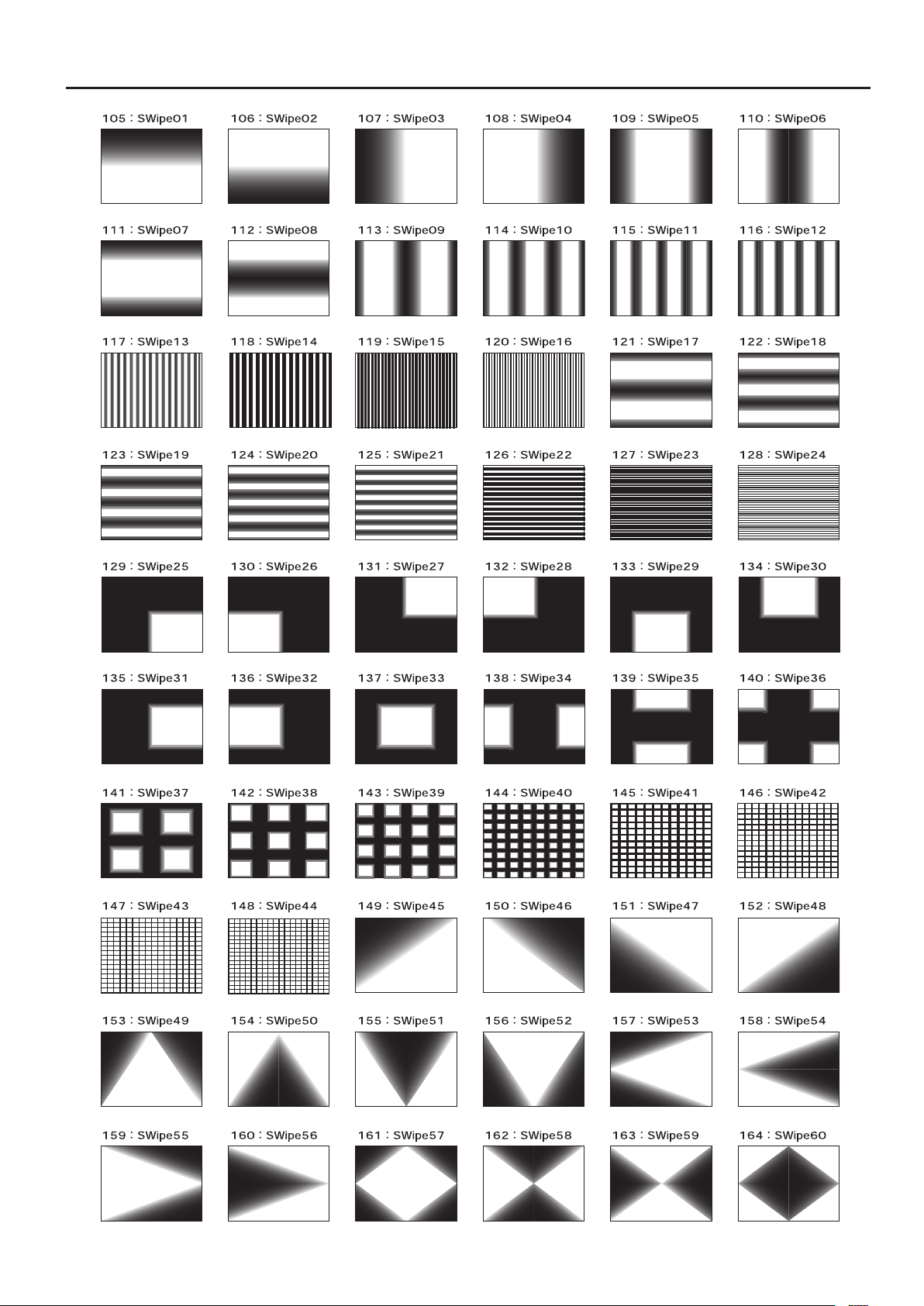
Appendices
49
Page 50
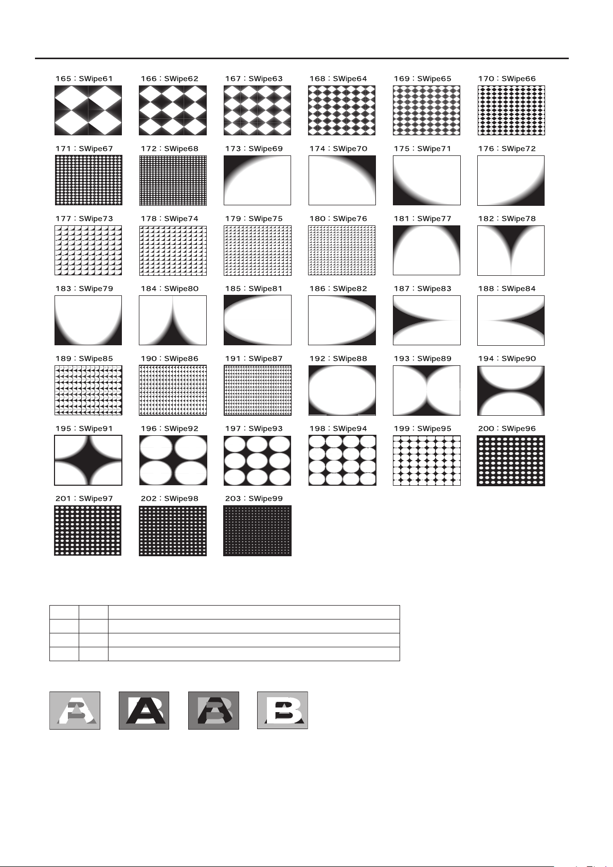
Appendices
Key
The transition starts at light areas or dark areas.
204 Key01 The dark part of the A-Bus picture transitions to the light part of the B-Bus picture.
205 Key02 The light part of the A-Bus picture transitions to the dark part of the B-Bus picture.
206 Key03 The light part of the B-Bus picture transitions to the dark part of the A-Bus picture.
207 Key04 The dark part of the B-Bus picture transitions to the light part of the A-Bus picture.
g.key-icons.eps
204 : Key01 205 : Key02 206 : Key03 207 : Key04
50
Page 51
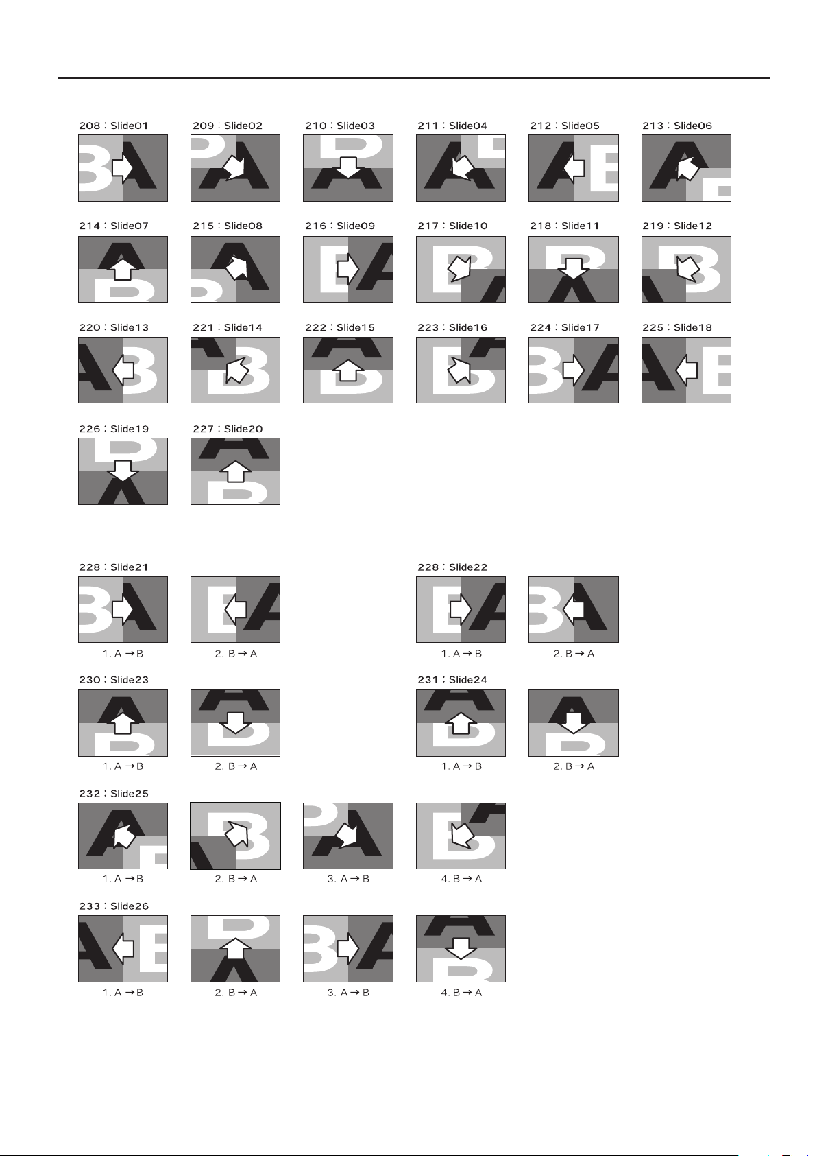
Slide (Normal)
Appendices
Slide (Sequential)
51
Page 52
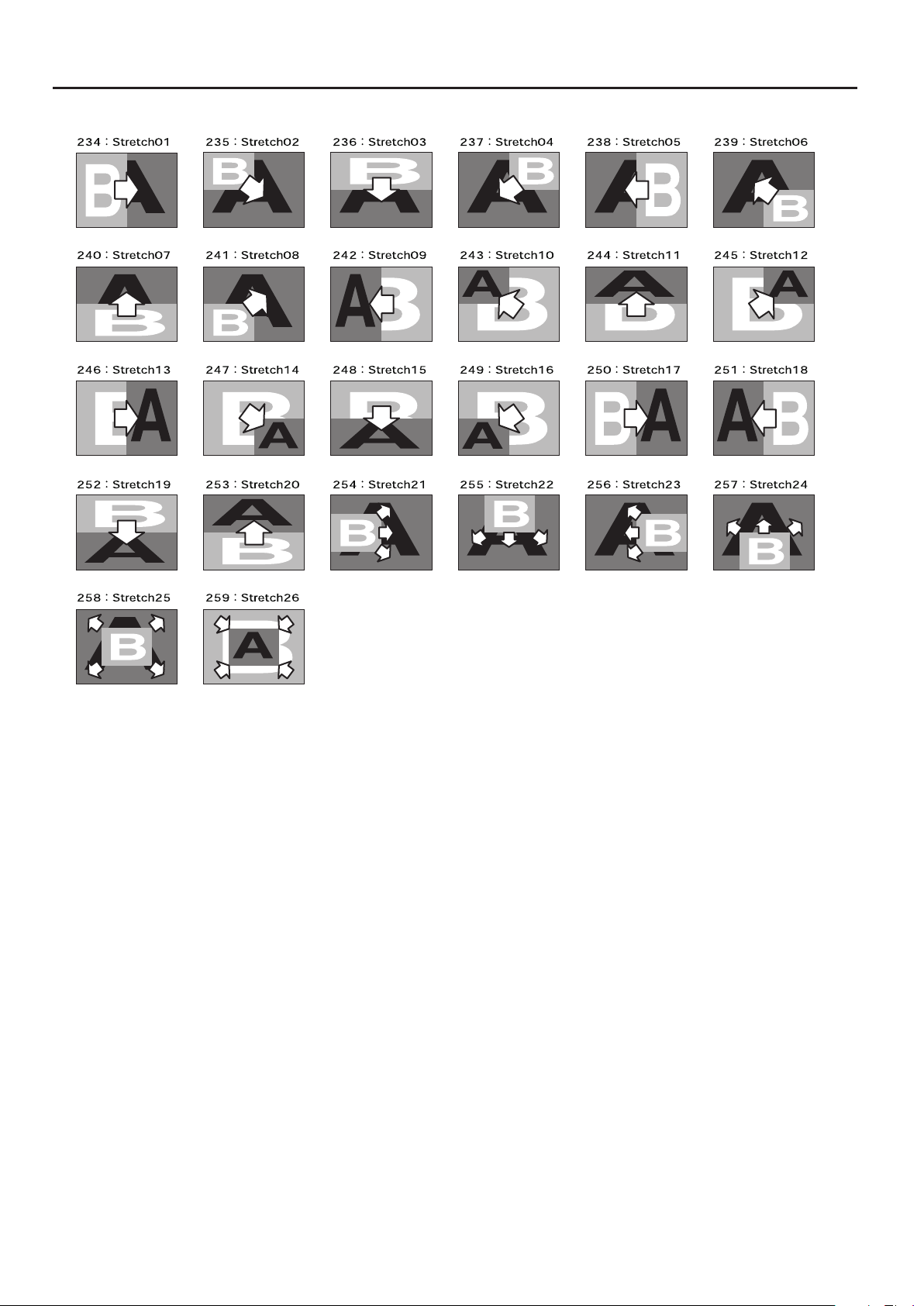
Appendices
Stretch
52
Page 53
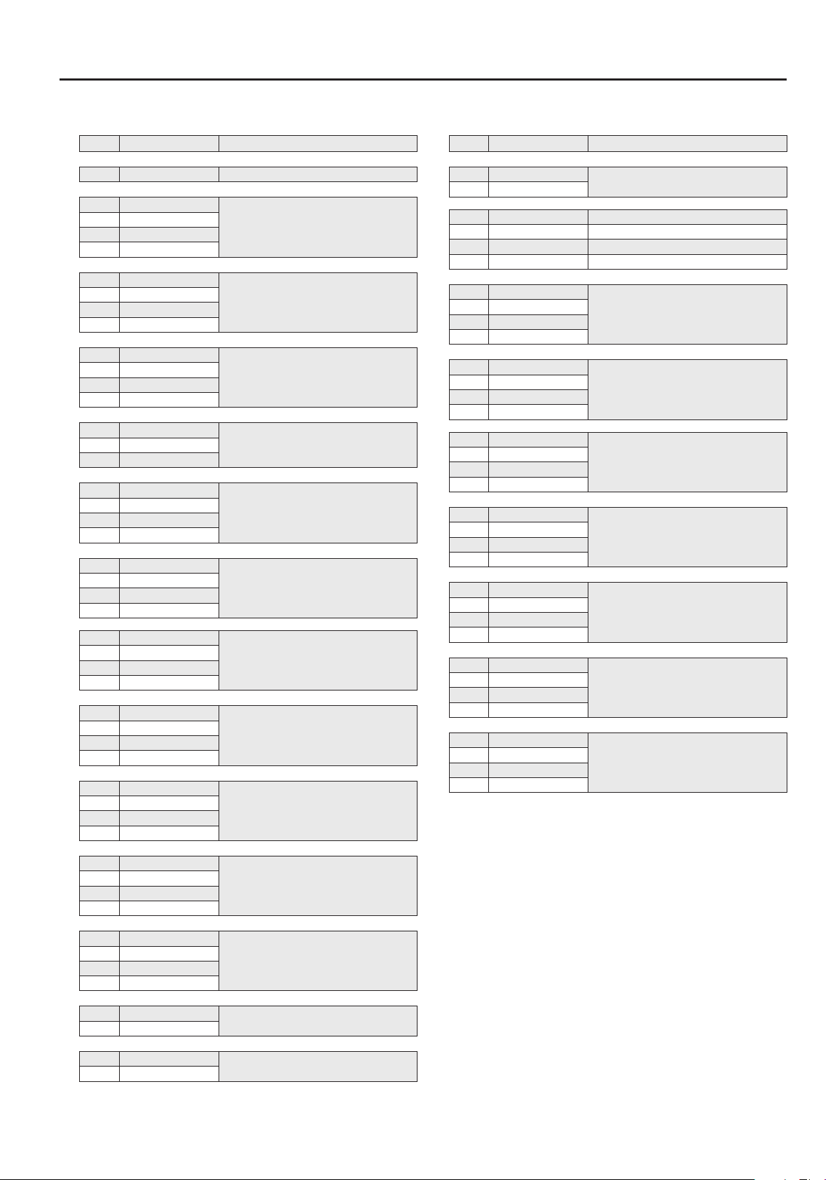
Filter/Compositing Eects
Appendices
No. Eect name Description
001 STILL Still (Field Freeze)
002 STROBE1
: :
010 STROBE9
011 STROBE*
012 AFTERIMAGE1
: :
015 AFTERIMAGE4
016 AFTERIMAGE*
017 FEEDBACK1
: :
020 FEEDBACK4
021 FEEDBACK*
022 SHAKE1*
027 SHAKE6*
028 NEGATIVE1
: :
030 NEGATIVE3
031 NEGATIVE*
032 COLORIZE1
: :
039 COLORIZE8
040 COLORIZE*
041 FINDEDGE1
: :
048 FINDEDGE8
049 FINDEDGE*
050 SILHOUETTE1
: :
057 SILHOUETTE8
058 SILHOUETTE*
059 MONOCOLOR1
: :
066 MONOCOLOR8
067 MONOCOLOR*
Strobe
Afterimage (image-trailer eect)
Feedback (repeated layering of the
picture upon itself)
Shake: :
Negative (inversion of brightness/color)
Colorize (addition of color to the picture)
Find edge (extraction of outlines)
Silhouette (dividing the picture into light
and dark areas, blackening dark areas,
and applying dierent color to light
areas)
Monocolor (single-color lter)
No. Eect name Description
095 CHROMAKEY
096 CHROMAKEY*
097 FLIP-H Flip (left/right ip)
098 FLIP-V Flip (top/bottom ip)
099 FLIP-HV Flip top/bottom and left/right ip)
100 FLIP* Flip (variable)
101 MULTI-H1
: :
107 MULTI-H7
108 MULTI-H*
109 MULTI-V1
: :
115 MULTI-V7
116 MULTI-V*
117 MULTI-HV1
: :
123 MULTI-HV7
124 MULTI-HV*
125 MIRROR-H1
: :
128 MIRROR-H4
129 MIRROR-H*
130 MIRROR-V1
: :
133 MIRROR-V4
134 MIRROR-V*
135 MIRROR-HV1
: :
138 MIRROR-HV4
139 MIRROR-HV*
140 PinP1
: :
147 PinP8
148 PinP*
Chroma key
Multi-screen (divided horizontally)
Multi-screen (divided vertically)
Multi-screen (divided horizontally and
vertically)
Mirror (divided horizontally)
Mirror (divided vertically)
Mirror (divided horizontally and
vertically)
Picture-in-Picture
068 EMBOSS1
: :
075 EMBOSS8
076 EMBOSS*
082 COLORPASS1
: :
089 COLORPASS8
090 COLORPASS*
091 W-LUMIKEY
092 W-LUMIKEY*
093 B-LUMIKEY
094 B-LUMIKEY*
Emboss (concave/convex image)
Color pass (making monochrome while
leaving a specic color)
Luminance key (white extraction)
Luminance key (black extraction)
53
Page 54
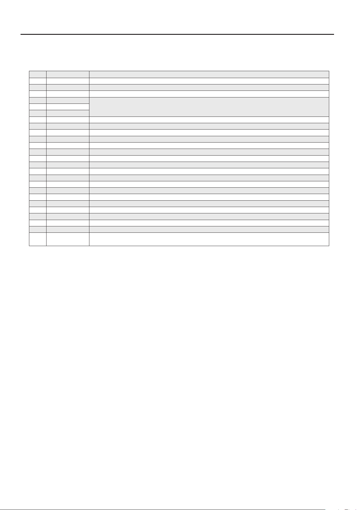
Appendices
Eects that Can Be Controlled by the [CONTROL] Dial
If you have assigned an eect that has an “*“ (asterisk) following its eect name, you can use the [CONTROL] dial to modify the
following settings. The EFFECTS button whose settings can be modied will ash.
No. Eect name Setting controlled by the [CONTROL] dial
011 STROBE* Change the spacing at which the still images will be output (nine levels).
016 AFTERIMAGE* Change the time that the afterimage is shown (four levels).
021 FEEDBACK* Change the strength of the eect over four levels.
022 SHAKE1*
Adjusts the speed at which the image will shake.:
026 SHAKE6*
031 NEGATIVE* Change the portion that is inverted (Invert brightness and color > Invert color > Invert brightness >).
040 COLORIZE] Change the colorization pattern (eight types).
049 FINDEDGE] Smoothly changes the color of the outline edge and background.
058 SILHOUETTE] Smoothly changes the color applied to the image.
067 MONOCOLOR] Smoothly changes the color of the color lter.
076 EMBOSS] Smoothly changes the color applied to the image.
081 POSTERIZE] Change the strength of the eect (four levels).
090 COLORPASS] Change the color that remains (eight types).
092 W-LUMIKEY] Change the white luminance key level.
094 B-LUMIKEY] Change the black luminance key level.
096 CHROMAKEY ] Change the chromakey level.
100 FLIP] Change the direction in which the image is ipped (Flip left/right/top/bottom > Flip top/bottom > Flip left/right >).
108 MULTI-H] Change the pattern by which the image is divided vertically (seven types).
116 MULTI-V] Change the pattern by which the image is divided horizontally (seven types).
124 MULTI-HV] Change the pattern by which the image is divided horizontally and vertically (seven types).
129 MIRROR-H] Change the pattern by which the image is divided vertically (four types).
134 MIRROR-V ] Change the pattern by which the image is divided horizontally (four types).
139 MIRROR-HV ] Change the pattern by which the image is divided horizontally and vertically (four types).
148 PinP]
Changes the position (eight types) of the subscreen.
* The position of the subscreen will reect the [140: PinP1] -- [147: PinP8] settings.
54
Page 55
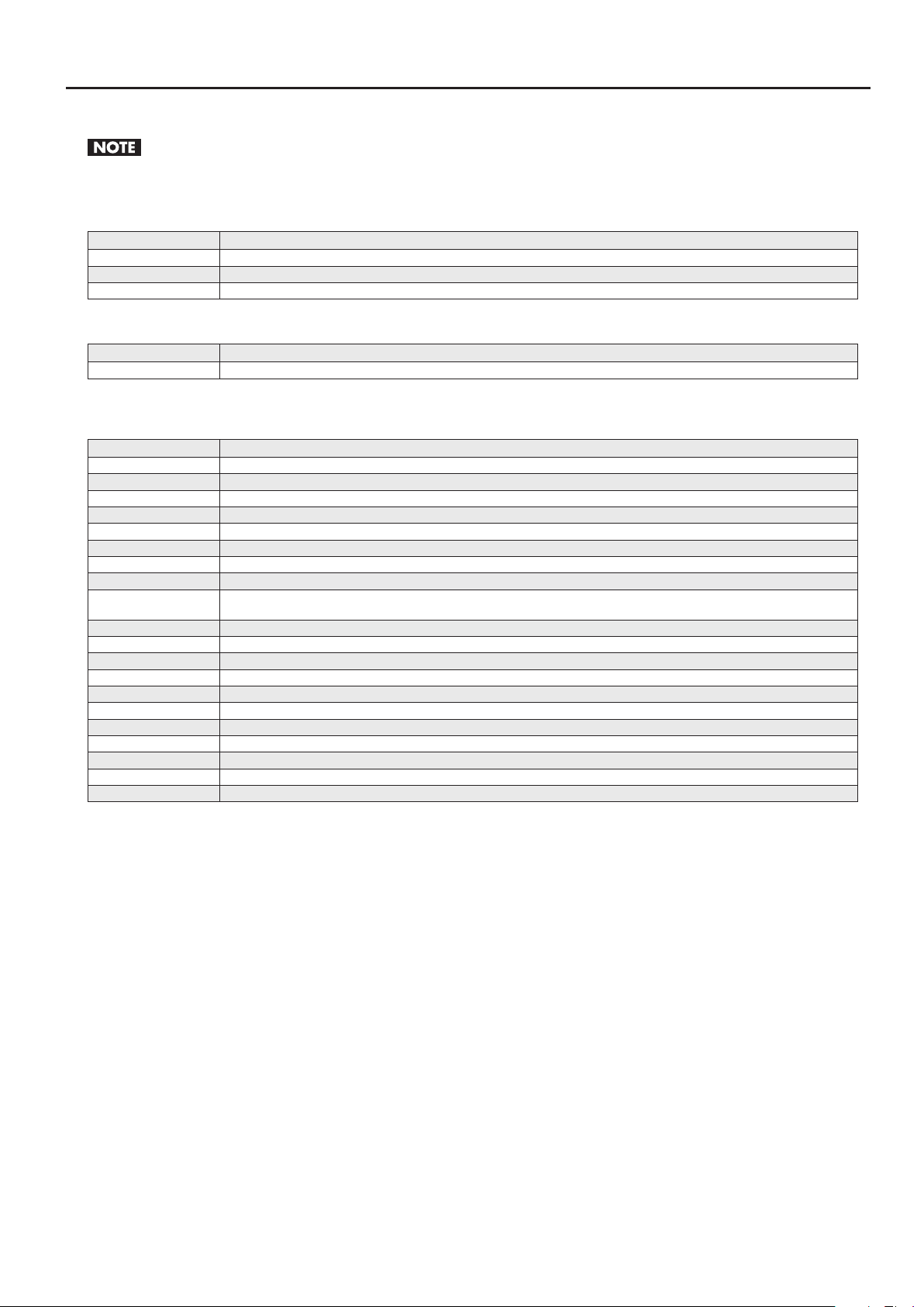
Eects That Cannot Be Used Simultaneously
The following eect combinations cannot be used simultaneously. When such eect is selected, the eect name is shown as [------] in the setup
screen (p. 26).
Combinations Composed of a Transition Eect and a Filter/Compositing Eect
Transition eect Filter/compositing eects that cannot be used simultaneously
Key SILHOUETTE, W-LUMIKEY, B-LUMIKEY, CHROMAKEY
Slide SILHOUETTE, SHAKE, W-LUMIKEY, B-LUMIKEY, CHROMAKEY, FLIP, MULTI, MIRROR, PinP
Stretch SILHOUETTE, SHAKE, W-LUMIKEY, B-LUMIKEY, CHROMAKEY, FLIP, MULTI, MIRROR, PinP
Combinations Composed of a Composition Eect and a Transition Eect
Composition eect Transition eects that cannot be used simultaneously
PinP Fam, Nam, Wipe, SWipe, Key, Slide, Stretch, User
* When PinP is turned on, the assigned eects to [TRANSITION] buttons are all changed to MIX for a while.
Combinations Composed of Two Filter/Compositing Eects
First eect Filter/compositing eects that cannot be used simultaneously
STILL STILL, STROBE, AFTERIMAGE, FEEDBACK, FINDEDGE, EMBOSS, MULTI, PinP
STROBE STILL, STROBE, FINDEDGE, EMBOSS, MULTI, PinP
AFTERIMAGE AFTERIMAGE, FEEDBACK(*1), SILHOUETTE, W-LUMIKEY, B-LUMIKEY, CHROMAKEY, PinP
FEEDBACK AFTERIMAGE(*2), FEEDBACK, SILHOUETTE, W-LUMIKEY, B-LUMIKEY, CHROMAKEY, PinP
SHAKE SHAKE, FLIP, MULTI, MIRROR, PinP
NEGATIVE NEGATIVE, COLORIZE, FINDEDGE, SILHOUETTE, MONOCOLOR, EMBOSS, POSTERIZE, COLORPASS
COLORIZE NEGATIVE, COLORIZE, FINDEDGE, SILHOUETTE, MONOCOLOR, EMBOSS, POSTERIZE, COLORPASS
FINDEDGE NEGATIVE, COLORIZE, FINDEDGE, SILHOUETTE, MONOCOLOR, EMBOSS, POSTERIZE, COLORPASS
SILHOUETTE
MONOCOLOR NEGATIVE, COLORIZE, FINDEDGE, SILHOUETTE, MONOCOLOR, EMBOSS, POSTERIZE, COLORPASS
EMBOSS NEGATIVE, COLORIZE, FINDEDGE, SILHOUETTE, MONOCOLOR, EMBOSS, POSTERIZE, COLORPASS
POSTERIZE NEGATIVE, COLORIZE, FINDEDGE, SILHOUETTE, MONOCOLOR, EMBOSS, POSTERIZE, COLORPASS
COLORPASS NEGATIVE, COLORIZE, FINDEDGE, SILHOUETTE, MONOCOLOR, EMBOSS, POSTERIZE, COLORPASS
W-LUMIKEY AFTERIMAGE, FEEDBACK, SILHOUETTE, W-LUMIKEY, B-LUMIKEY, CHROMAKEY
B-LUMIKEY AFTERIMAGE, FEEDBACK, SILHOUETTE, W-LUMIKEY, B-LUMIKEY, CHROMAKEY
CHROMAKEY AFTERIMAGE, FEEDBACK, SILHOUETTE, W-LUMIKEY, B-LUMIKEY, CHROMAKEY
FLIP STILL(*3), STROBE (*3), SHAKE, FLIP, MULTI, MIRROR, PinP
MULTI STILL(*4), STROBE (*4), SHAKE, FLIP, MULTI, MIRROR, PinP
MIRROR STILL(*5), STROBE (*5), SHAKE, FLIP, MULTI, MIRROR, PinP
PinP STILL(*6), STROBE(*6), AFTERIMAGE, FEEDBACK, SHAKE, SILHOUETTE, FLIP, MULTI, MIRROR, PinP,
AFTERIMAGE, FEEDBACK, NEGATIVE, COLORIZE, FINDEDGE, SILHOUETTE, MONOCOLOR, EMBOSS, POSTERIZE, COLORPASS,
W-LUMIKEY, B-LUMIKEY, CHROMAKEY, PinP
Appendices
*1 “FEEDBACK” takes priority for both A-Bus and B-Bus.
*2 “AFTERIMAGE” takes priority for both A-Bus and B-Bus.
*3 When “FLIP*” is on, operating [CONTROL] turns o “STILL” or “STROBE.”
*4 When “MULTI-H*,” “MULTI-V*,” or “MULTI-HV*” is on, operating [CONTROL] turns o “STILL” or “STROBE.”
*5 When “MIRROR-H*,” “MIRROR-V*,” or “MIRROR-HV*” is on, operating [CONTROL] turns o “STILL” or “STROBE.”
*6 When “PinP*” is on, operating [CONTROL] turns o “STILL” or “STROBE.”
55
Page 56
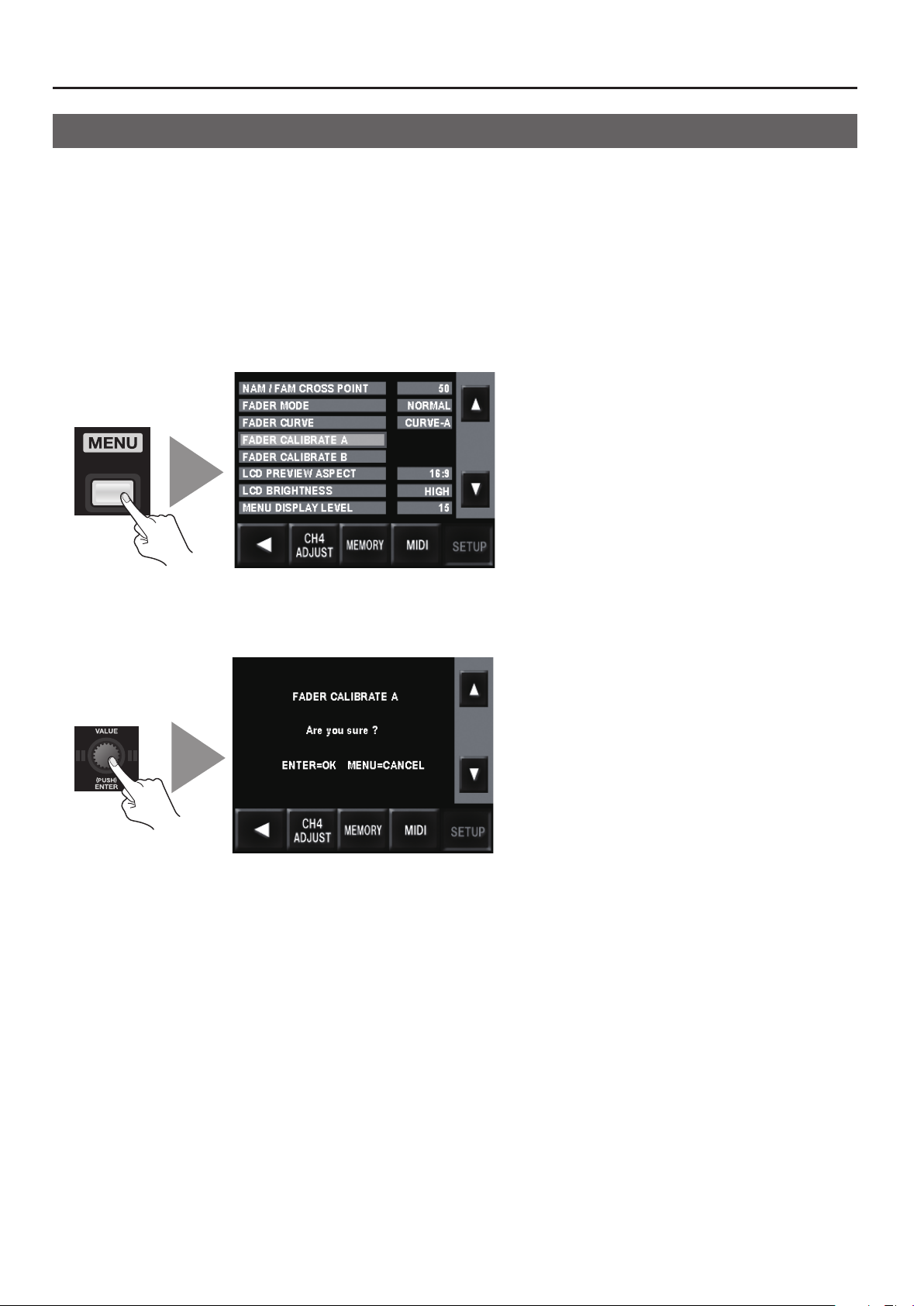
Appendices
Calibrating and Changing the Installed Orientation of the Video Fader
Calibrating the Video Fader
After repeated use of the V-4EX, you may nd that 100% of the image is not output even when you’ve moved the video fader all the
way toward A-Bus or B-Bus. If this occurs, perform calibration of the video fader.
1. Move to the A-Bus end.
Move the video fader all the way toward the A-Bus position.
2. Access the SETUP menu.
Press the [MENU] button to access the menu screen, then use the touch panel to select [SETUP].
g.utility-menu.eps
3. Calibrate the A-Bus position.
Select [FADER CALIBRATE A] and press the [VALUE] dial. The display changes to a conrmation screen. Press the [VALUE] dial once more.
g.calibrate-menu.eps
4. Move to the B-Bus end.
Move the video fader all the way to the B-Bus position.
5. Calibrate the B-Bus position.
Select [FADER CALIBRATE B] and press the [VALUE] dial. The display changes to a conrmation screen. Press the [VALUE] dial once more.
6. Go back to the original screen.
Press the [MENU] button several times to quit the menu screen and go back to the original screen.
56
Page 57
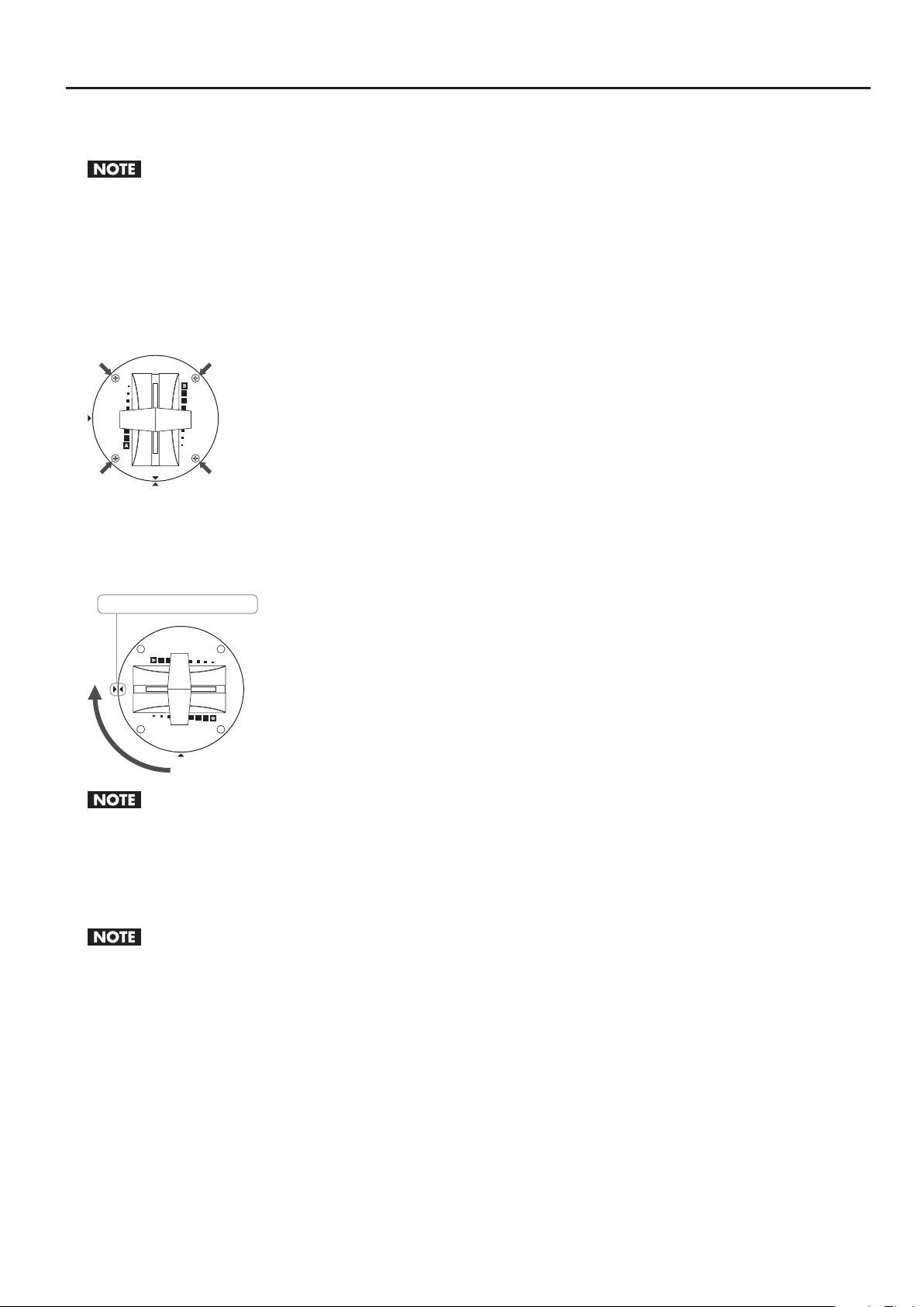
Changing the Installed Orientation of the Video Fader
You can change the orientation in which the video fader is installed by 90 degrees.
Before you remove the video fader, turn o the power to the unit and unplug the AC adapter from the power outlet.
1. Turn o the power.
Before you attempt to change the orientation of the video fader, be sure to turn o the power to the V-4EX.
2. Remove the screws.
Remove the four screws shown below.
After you remove the screws, keep from touching the internal circuitry or connectors with your hands.
g.unscrew.eps
Appendices
3. Change the orientation of the video fader.
Rotate the video fader 90 degrees. When doing this, align the triangular symbol printed on the video fader panel (circular) with the
triangular symbol printed on the V-4EX’s top panel.
g.turn-fader.eps
Align the triangular symbols.
When changing the orientation of the video fader, never pull the video fader upward or rotate it more than 90 degrees. Doing so may disconnect or
break the cable that connects the video fader to the V-4EX.
4. Secure the video fader in place.
Using the screws you removed in step 2, fasten the video fader panel to the top panel of the V-4EX. After securing it in place, check
again to make sure it is installed correctly.
When fastening, never use and screws other than the ones you removed in step 2.
57
Page 58
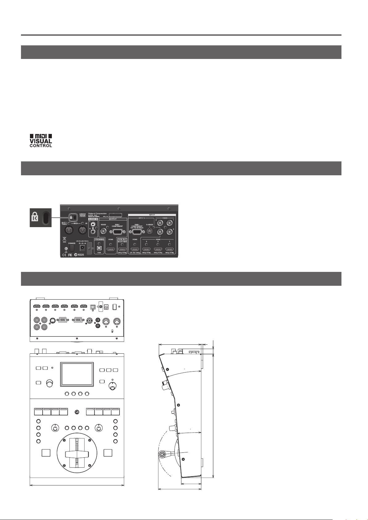
Appendices
About Remote Control
MIDI and USB
The V-4EX supports remote control by MIDI or USB, and can be operated remotely from an external device. When performing
remote control, download “Remote Control Guide” from the following Roland website.
http://www.rolandsystemsgroup.net/
MIDI VISUAL CONTROL
The V-4EX can be operated remotely from a device that supports MIDI Visual Control. MIDI Visual Control is a feature that uses MIDI
to link visual expression to a musical performance.
g.MVC-logo.eps
Security Slot
You can attach a commercially available security wire here to prevent theft.
http://www.kensington.com/
g.kensington.eps
Dimensions
g.dimension.eps
Unit : mm
101
2
4
11.8
0
296
5
58
225
47.6
102.5
Page 59

Appendices
Troubleshooting
The volume level of equipment connected to the AUDIO IN jacks is too low.
Are you using connection cables that contain resistors? Use connector cables that do not contain resistors.
No input picture is displayed.
Is a device that does not support 480p or 576p output connected to INPUT 1, 2, or 3? Connect such unsupported equipment to
INPUT 4.
No signal is output from the RGB/COMPONENT connector or the composite jack.
Is HDCP turned on? Turning on HDCP stops RGB/component, composite and USB output. Note, however, that HDCP-applied signals
continue to be output from the HDMI connectors. Refer to “Inputting HDCP Signals” (p. 24).
The color of the picture output from the RGB/COMPONENT connector is strange.
Has the precise output format been selected? When an interlaced output format is selected, component signals are output from
the RGB/COMPONENT connector. When a noninterlaced format is selected, RGB signals are output from the RGB/COMPONENT
connector.
A-Bus or B-Bus does not transition completely.
If output of a slight amount of the picture on the opposite bus continues even when the control has been moved all the way, carry
out the procedure in “Calibrating the Video Fader” (p. 56).
Nothing is displayed on the preview monitor.
Does the connected monitor support 480/59.94p (when set to NTSC) or 576/50p (when set to PAL)? Connect equipment that
supports these output formats.
Nothing is displayed on the built-in monitor.
Is any of the MONITOR buttons illuminated? Nothing is displayed when all are dark.
Video cannot be switched using the touch panel.
Has the video fader been moved all the way to one end of its stroke? The touch panel cannot be used to perform a transition when
the video fader has not been moved all the way. The touch panel also cannot be used to perform a transition while a menu is
displayed.
Fade cannot be applied to output.
Has operation of the [OUTPUT FADE] dial been disabled? When [OUT-FADE] has been set to [No Ctrl] at the setup screens, the dial
cannot be used to apply fade.
Panel settings cannot be saved.
Is [1] selected by the MEMORY dial? Settings cannot be saved when the dial is at [1]. Select a dierent number before changing
settings.
Are settings protected? Even when a number other than [1] is selected, settings cannot be saved if they are protected. Go to the
MEMORY menu and set [PROTECT] to [OFF].
The stroke ends of the video fader are unresponsive.
Is the operating curve set to [Curve B] or [Curve C]? When the setting is Curve B, the end areas are less sensitive. When the setting is
Curve C, the end areas are completely unresponsive. Going to the SETUP menu and selecting [Curve A] for [FADER CURVE] makes it
possible to use the full length of the stroke.
Two eects cannot be used simultaneously.
With some combinations of eects, using two eects simultaneously is not possible. Refer to “Eects That Cannot Be Used
Simultaneously” (p. 54).
59
Page 60

Index
A
Audio Balance ................................................... 36
Audio Source .................................................... 18
AUTO OFF ....................................................... 10
B
BPM ............................................................. 29
C
Calibrate ........................................................ 56
Chroma Key ..................................................... 33
Component ..................................................... 17
Composite ...................................................... 16
Computer ....................................................... 20
Cord Hook ......................................................... 9
D
delay ............................................................ 37
E
Eects List ....................................................... 46
Enabled Connector .............................................. 17
F
Fade ............................................................ 31
Filter ............................................................ 32
Formats ......................................................... 23
freeze ........................................................... 31
T
Touch Panel ..................................................... 28
transition eect ................................................. 27
Transition Section ............................................... 13
U
User Transition .................................................. 42
V
Video Fader ..................................................... 27
View Mode ...................................................... 25
Volume. . . . . . . . . . . . . . . . . . . . . . . . . . . . . . . . . . . . . . . . . . . . . . . . . . . . . . . . . . 36
H
HDCP ........................................................... 24
HDMI. . . . . . . . . . . . . . . . . . . . . . . . . . . . . . . . . . . . . . . . . . . . . . . . . . . . . . . . . . . . 16
L
Lip-sync ......................................................... 37
Luminance Key .................................................. 34
M
MEMORY ........................................................ 38
Menu ........................................................... 40
MIDI ............................................................ 58
MIDI VISUAL CONTROL ........................................... 58
Monitor ......................................................... 11
O
Operating System ............................................... 20
Orientation ...................................................... 57
P
Picture-in-Picture ................................................ 35
Preview Monitor ................................................. 19
Projector ........................................................ 19
R
Remote Control ................................................. 58
RGB ............................................................. 17
S
Signal Flow ...................................................... 15
Source .......................................................... 16
Streaming ....................................................... 20
S-Video .......................................................... 16
Switching ....................................................... 27
60
Page 61
Model Name :
Type of Equipment :
Responsible Party :
Address :
Telephone :
V-4EX
Video Mixer
Roland Systems Group U.S.
5100 S.Eastern Avenue, Los Angeles, CA 90040-2938, U.S.A.
(323) 890 3700
61
Page 62
62
Page 63
63
Page 64

 Loading...