

Page 1

Thank you very much for purchasing this product.
To ensure correct and safe usage with a full understanding of this product's performance, please be sure to read
through this manual completely and store it in a safe location.
Unauthorized copying or transferral, in whole or in part, of this manual is prohibited.
The contents of this operation manual and the specifications of this product are subject to change without notice.
The operation manual and the product have been prepared and tested as much as possible. If you find any mis-
print or error, please inform us.
Roland DG Corp. assumes no responsibility for any direct or indirect loss or damage which may occur through
use of this product, regardless of any failure to perform on the part of this product.
Roland DG Corp. assumes no responsibility for any direct or indirect loss or damage which may occur with respect
to any article made using this product.
R9-171102
Page 2

Page 3
For the USA
FEDERAL COMMUNICATIONS COMMIS-
SION RADIO FREQUENCY INTERFERENCE
STATEMENT
NOTE:
This equipment has been tested and found to comply with the
limits for a Class A digital device, pursuant to part 15 of the
FCC Rules. These limits are designed to provide reasonable
protection against harmful interference when the equipment
is operated in a commercial environment. This equipment
generates, uses, and can radiate radio frequency energy and, if
not installed and used in accordance with the instruction manual, may cause harmful interference to radio communications.
Operation of this equipment in a residential area is likely
to cause harmful interference in which case the user will be
required to correct the interference at his own expense.
Unauthorized changes or modication to this system can void
the users authority to operate this equipment.
Use only I/O cables that have been designed and manufac-
tured specically for this device.
For Canada
NOTICE
This Class A digital apparatus meets all requirements of the
Canadian Interference-Causing Equipment Regulations.
AVIS
Cet appareil numerique de la classe A respecte toutes
les exigences du Reglement sur le materiel brouileur du
Canada.
For California
WARNING:
State of California to cause cancer and birth defects or other reproductive harm. For more
information go to www.P65Warnings.ca.gov.
This product can expose you to chemicals including lead, which is known to the
For EU Countries
WARNING
This is a Class A product. In a domestic environment this product may cause radio interference in
which case the user may be required to take adequate measures.
For EU Countries
Manufacturer:
ROLAND DG CORPORATION
1-6-4 Shinmiyakoda, Kita-ku, Hamamatsu-shi, Shizuoka-ken, 431-2103 JAPAN
The importer in the EU:
Roland DG Europe Holdings B.V.
Prof. J.H. Bavincklaan 2, 1183 AT, Amstelveen, The Netherlands
RolandDG Corp. has licensed the MMP technology from the TPL Group.
1
Page 4

For China
产品中有毒有害物质或元素的名称及含量
有毒有害物质或元素
部件名称
印刷电路板 × ○ × ○ ○ ○
头部 × ○ ○ ○ ○ ○
壳体、底架 × ○ ○ ○ ○ ○
电源 × ○ × ○ ○ ○
其他(电缆、附件等) × ○ ○ ○ ○ ○
○:表示该有毒有害物质在该部件所有均质材料中的含量均在 GB/T26572-2011 标准规定的限量要求以下。
×:表示该有毒有害物质至少在该部件的某一均质材料中的含量超出 GB/T26572-2011 标准规定的限量要求。
环
保使用期限
铅(Pb) 汞(Hg) 镉(Cd)
此标志适用于在中国国内销售的电子信息产品,表示环保使用期限的年数。
所谓环保使用期限是指在自制造日起的规定期限内,产品中所含的有害物质
不致引起环境污染,不会对人身、财产造成严重的不良影响。
环保使用期限仅在遵照产品使用说明书,正确使用产品的条件下才有效。
不当的使用,将会导致有害物质泄漏的危险。
六价铬
(Cr(Ⅵ))
多溴联苯
(PBB)
多溴二苯醚
(PBDE)
For EU Countries
This product must be disposed of
separately at your local waste recycling
center. Do not dispose of in household
waste bin.
Bitte führen Sie dieses Produkt separat
Ihrer örtlichen Entsorgungsstelle zu.
Bitte nicht mit dem normalen Hausmüll
entsorgen.
Ne jetez pas le produit avec vos
ordures ménagères. Portez-le dans un
centre recyclage des déchets.
Questo prodotto deve essere smaltito
negli appositi contenitori per la raccolta
differenziata, non buttare nel cestino
dei rifiuti casalinghi.
Este producto debe devolverse al
centro de reciclaje más cercano a su
domicilio para su correcta eliminación.
No lo tire a la basura.
Lever dit product in bij een lokaal
afvalverzamelpunt. NIET met normaal
huishoudelijk afval afvoeren.
Dette Produkt skal smides særskilt
væk på den lokale affalds- og
genbrugsstation. Må ikke smides ud
sammen med almindeligt
husholdningsaffald.
Tätä tuotetta ei saa hävittää
normaalien talousjätteiden mukana,
vaan se on toimitettava
ongelmajätteiden keräilypisteeseen
hävitettäväksi.
Produkten måste kasseras separat på
din lokala återvinningscentral. Släng
inte produkten tillsammans med
hushållssoporna.
Μην πετάξετε το αντικείμενο αυτό στο
καλάθι των απορριμμάτων. Αφαιρέστε
τις μπαταρίες και προσκομίστε το στο
τοπικό κέντρο ανακύκλωσης.
Deite fora separadamente este produto
no seu centro de reciclagem local. Não
o deite fora no seu caixote do lixo.
2
Page 5

Contents
Contents ...................................................................................................................................... 3
To Ensure Safe Use ............................................................................................................... 4
Important Notes on Handling and Use ....................................................................................... 8
User's Manual .....................................................................................................................................9
1. Getting Started ...................................................................................................................... 10
System Features ...........................................................................................................................................................................10
Main Compatible Models (As of April 2016) ......................................................................................................................10
Changes in Printer Functioning .............................................................................................................................................10
Part Names and Functions .......................................................................................................................................................11
2. Checking the Included Items ................................................................................................. 12
3. Assembling and Installing ......................................................................................................14
Read This First .............................................................................................................................................................................. 14
Assembling and Installing ........................................................................................................................................................14
4. Operation ..............................................................................................................................22
Operating Conditions for the Take-up Unit .......................................................................................................................22
About the Paper Tube ................................................................................................................................................................22
How to Load Media .....................................................................................................................................................................23
To Take Up Media Manually .....................................................................................................................................................29
How to Remove Taken-up Media ...........................................................................................................................................30
5. What to do if... ....................................................................................................................... 31
The Take-up Unit Doesn't Take Up Media. ..........................................................................................................................31
Media Take-up Is Not Straight. ................................................................................................................................................ 31
6. Appendix ...............................................................................................................................32
Locations of the Power Rating and Serial Number Labels............................................................................................32
Specications ................................................................................................................................................................................32
Company names and product names are trademarks or registered trademarks of their respective holders.
Copyright © 2008-2017 Roland DG Corporation
http://www.rolanddg.com/
3
Page 6

To Ensure Safe Use
Improper handling or operation of this machine may result in injury or damage to property. Points which
must be observed to prevent such injury or damage are described as follows.
About WARNING and CAUTION Notices
WARNING
CAUTION
Used for instructions intended to alert the user to the risk of death or severe
injury should the unit be used improperly.
Used for instructions intended to alert the user to the risk of injury or material
damage should the unit be used improperly.
* Material damage refers to damage or other adverse effects caused with
About the Symbols
The symbol alerts the user to important instructions or warnings. The specic mean-
ing of the symbol is determined by the design contained within the triangle. The symbol
at left means "danger of electrocution."
The symbol alerts the user to items that must never be carried out (are forbidden).
The specic thing that must not be done is indicated by the design contained within the
circle. The symbol at left means the unit must never be disassembled.
The symbol alerts the user to things that must be carried out. The specic thing that
must be done is indicated by the design contained within the circle. The symbol at left
means the power-cord plug must be unplugged from the outlet.
respect to the home and all its furnishings, as well to domestic animals or
pets.
Media weighs 30 kg (66 lb.)
WARNING
Handling roll media is an operation that
must be performed by two persons or
more, and care must be taken to prevent
falls.
Attempting to lift heavy media in a manner
that taxes your strength may cause physical
injury.
When storing roll media, implement adequate safety measures to ensure that the
stored media will not roll, fall, or topple
over.
Danger exists of becoming pinned under the
media and suffering serious injury.
4
WARNING
If the printer’s usable media weight is less
than 30 kilograms (66 lb.), media weighing
more than this cannot be used.
Page 7

To Ensure Safe Use
Incorrect operation may cause injury.
WARNING
Be sure to follow the operation procedures
described in this documentation. Never
allow anyone unfamiliar with the usage or
handling of the machine to touch it.
Incorrect usage or handling may lead to an
accident.
Keep children away from the machine.
The machine includes areas and components
that pose a hazard to children and may result
in injury, blindness, choking, or other serious
accident.
Never operate the machine while tired or
after ingesting alcohol or any medication.
Operation requires unimpaired judgment. Impaired judgment may result in an accident.
Never use the machine for any purpose
for which it is not intended, or use the
machine in an undue manner that exceeds
its capacity.
Doing so may result in injury or re.
For accessories (optional and consumable
items, AC adapter, power cord, and the
like), use only genuine articles compatible
with this machine.
Incompatible items may lead to an accident.
CAUTION
Exercise caution to avoid being pinched or
becoming caught.
Inadvertent contact with certain areas may
cause the hand or ngers to be pinched or
become caught. Use care when performing
operations.
Never attempt operation while wearing a
necktie, necklace, or loose clothing. Bind
long hair securely.
Such items may become caught in the machine, resulting in injury.
Conduct operations in a clean, brightly lit
location.
Working in a location that is dark or cluttered
may lead to an accident, such as becoming
caught in the machine as the result of an inadvertent stumble.
Never climb or lean on the machine.
The machine is not made to support a person. Climbing or leaning on the machine may
dislodge components and cause a slip or fall,
resulting in injury.
Before attempting cleaning, maintenance,
or attachment or detachment of optional
items, disconnect the power cord.
Attempting such operations while the machine
is connected to a power source may result in
injury or electrical shock.
Never attempt to disassemble, repair, or
modify the machine.
Doing so may result in re, electrical shock,
or injury. Entrust repairs to a trained service
technician.
5
Page 8
To Ensure Safe Use
Danger of electrical short, shock, electrocution, or re
WARNING
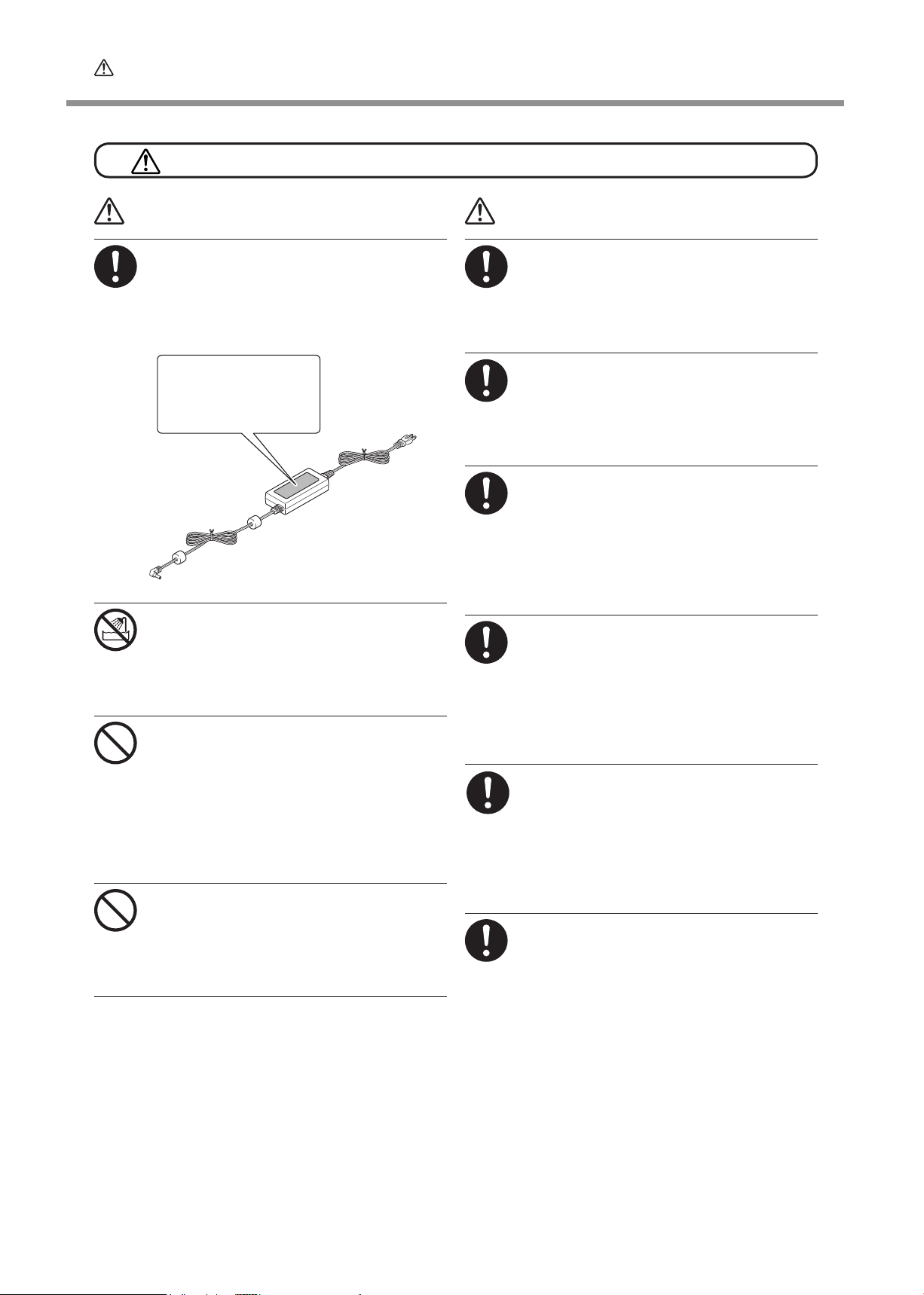
Connect to an electrical outlet that complies with this machine's ratings (for voltage, frequency, and current).
Incorrect voltage or insufcient current may
cause re or electrical shock.
Ratings
Never use out of doors or in any location
where exposure to water or high humidity
may occur. Never touch with wet hands.
Doing so may result in fire or electrical
shock.
Never allow any foreign object to get inside.
Never expose to liquid spills.
Inserting objects such as coins or matches
or allowing beverages to be spilled into the
ventilation ports may result in re or electrical
shock. If anything gets inside, immediately
disconnect the power cord and contact your
authorized Roland DG Corp. dealer.
Never place any ammable object nearby.
Never use a combustible aerosol spray
nearby. Never use in any location where
gases can accumulate.
Combustion or explosion may be a danger.
WARNING
When the machine will be out of use
for a prolonged period, disconnect the
power cord.
This can prevent accidents in the event of
current leakage or unintended startup.
Handle the power cord, plug, and electrical
outlet correctly and with care. Never use
any article that is damaged.
Using a damaged article may result in re or
electrical shock.
When using an extension cord or power
strip, use one that adequately satises the
machine's ratings (for voltage, frequency,
and current).
Use of multiple electrical loads on a single
electrical outlet or of a lengthy extension cord
may cause re.
Position so that the power plug is within
immediate reach at all times.
This is to enable quick disconnection of the
power plug in the event of an emergency.
Install the machine next to an electrical outlet.
Also, provide enough empty space to allow
immediate access to the electrical outlet.
If sparking, smoke, burning odor, unusual sound, or abnormal operation occurs,
immediately unplug the power cord.
Never use if any component is damaged.
Continuing to use the machine may result in
re, electrical shock, or injury. Contact your
authorized Roland DG Corp. dealer.
Do not use the supplied power supply
cord for other products.
6
Page 9

Important notes about the power cord, plug, and electrical outlet
To Ensure Safe Use
Never place any object on top or subject to
damage.
Never bend or twist with undue force.
Never allow to get wet.
Never make hot.
Never pull with undue force.
Never bundle, bind, or roll up.
Dust may cause re.
7
Page 10

Important Notes on Handling and Use
This machine is a precision device. To ensure the full performance of this machine, be sure to observe the
following important points. Failure to observe these may not only result in loss of performance, but may
also cause malfunction or breakdown.
This Machine Is a Precision Device
Handle carefully, and never subject the machine to impact or excessive force.
Never cover the ventilation holes with cloth, tape, or anything else.
8
Page 11

User's Manual
9
Page 12

1. Getting Started
System Features
This is a take-up unit for large-format printers from Roland DG Corp.
This unit automatically takes up media as it is being printed. This enables lengthy output and unattended operation at
night to be accomplished eciently.
Media weighing up to 30 kilograms can be used. Stable take-up is possible even for heavy media. (If the printer's usable
media weight is less than 30 kilograms, media weighing more than this cannot be used.)
Main Compatible Models (As of April 2016)
TrueVIS series
PRO II/PRO II V series (including SOLJET PRO II V series, SOLJET PRO II series, Hi-Fi JET PRO II
series, CAMM JET PRO II series)
VersaCAMM series (including VS series, VP series, SP series)
VersaArt series (including RS series, RA series, RE series)
Changes in Printer Functioning
Installing this unit changes the printer's menus and other behavior in the following ways
VG-640/540, VS-640/540/420/300, VS-640i/540i/300i
At the [SETUP SHEET] screen, selecting whichever [ROLL], [TU], or [TU2] is now possible. When performing printing us-
ing this unit, select “TU2” (accompanying the pull-back operation) or “TU” (not accompanying the pull-back operation).
User’s Manual for the VS series, “Using Media Take-up System“ in “Chapter 4 Part of Practice“
RS-640/540, VP-540i/300i, SP-540i/300i, RA-640, RE-640
At the [SETUP SHEET] screen, selecting either [ROLL] or [TU] is now possible. When performing printing using this unit,
select [TU].
10
Page 13
Part Names and Functions
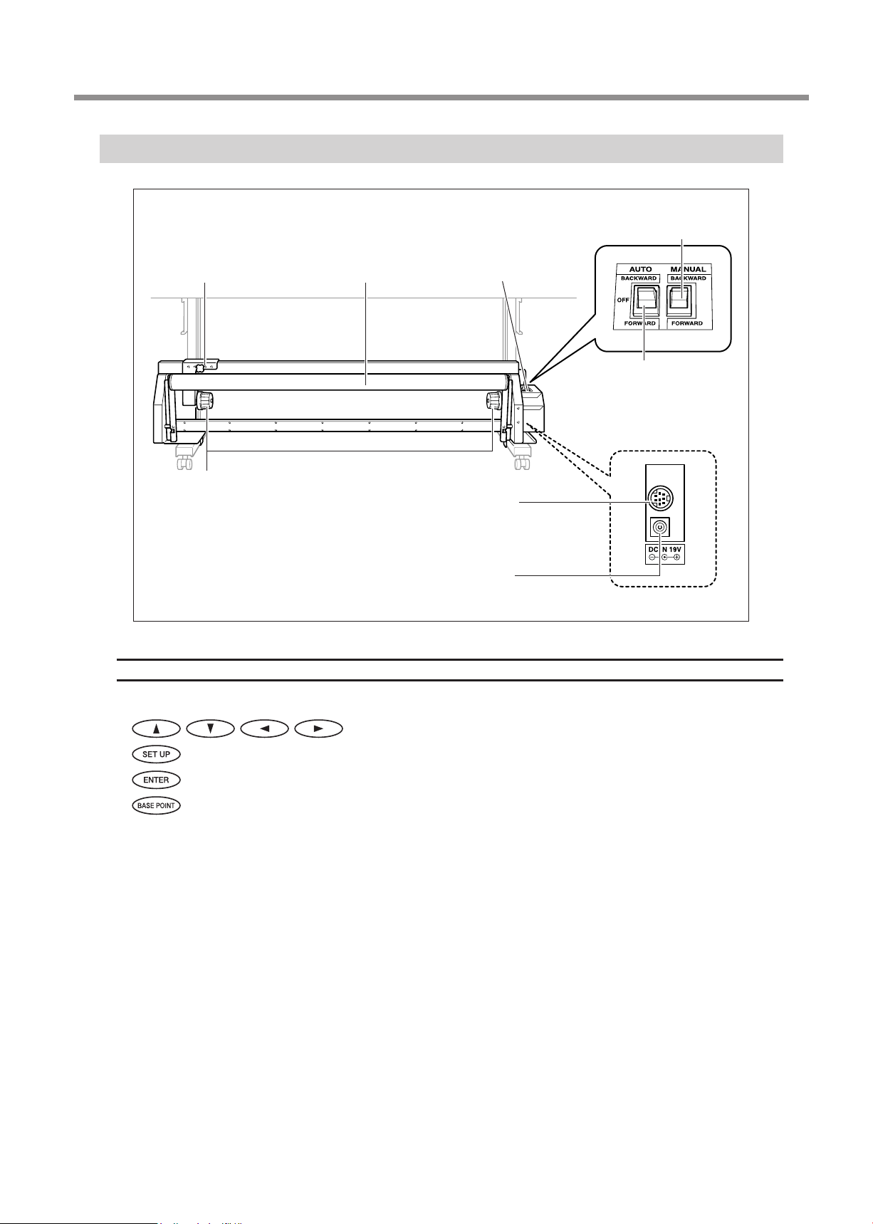
Arm
This is used to mount the
paper tube for take-up.
Dancer roller
This maintains uniform
tension for media.
Control box
This controls takeup of the media.
1. Getting Started
MANUAL switch
You use this when you want to
operate the take-up unit manually.
AUTO switch
This makes the direction of
rotation for take-up during
printing change automatically.
The back of the unit
End caps
Here is where you
mount the paper tube
for taking up media.
Printer connector
This connector is used for making the connection when using the
printer connector cable included with
the unit.
AC Adapter Jack
Here is where you connect the
included dedicated AC adapter.
About the Notation Used in This Manual
This document uses the following images to indicate the keys and lights on the printer's operation panel.
Cursor keys
SETUP key/light
ENTER key
BASE POINT key
11
Page 14
2. Checking the Included Items
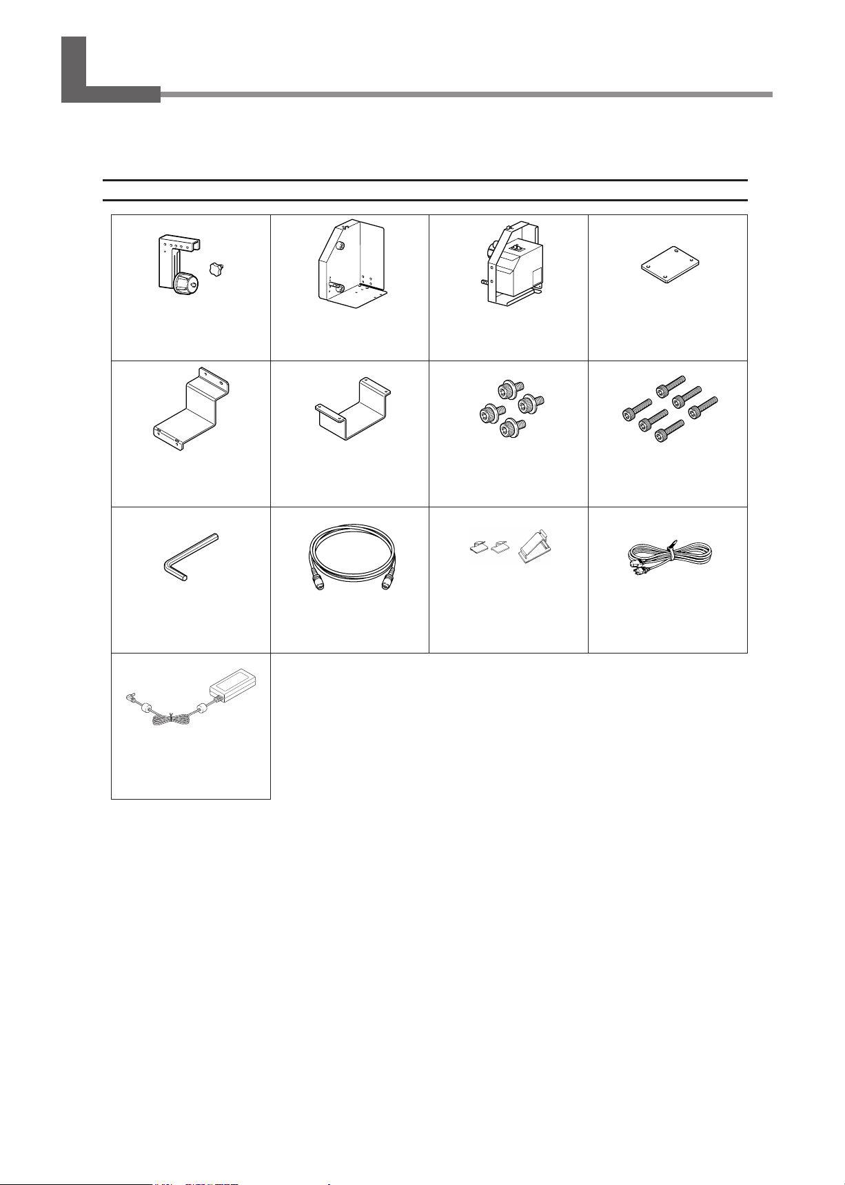
The following included items are contained in two packing cartons. Make sure they are all present and accounted for.
Control Box (TUC-2)
Arm/Arm retaining screw
(one for each)
Mounting xture B (1) Mounting xture C (1) Bolts with washers (4) Small Bolts (6)
Hex wrench (small) (1) Printer connector cable (1)
Frame (1) Control box (1) Mounting xture A (1)
Small
Cable clamps
(small) (2) (large) (1)
Large
Power Cord (1)
12
AC adapter (1)
Page 15
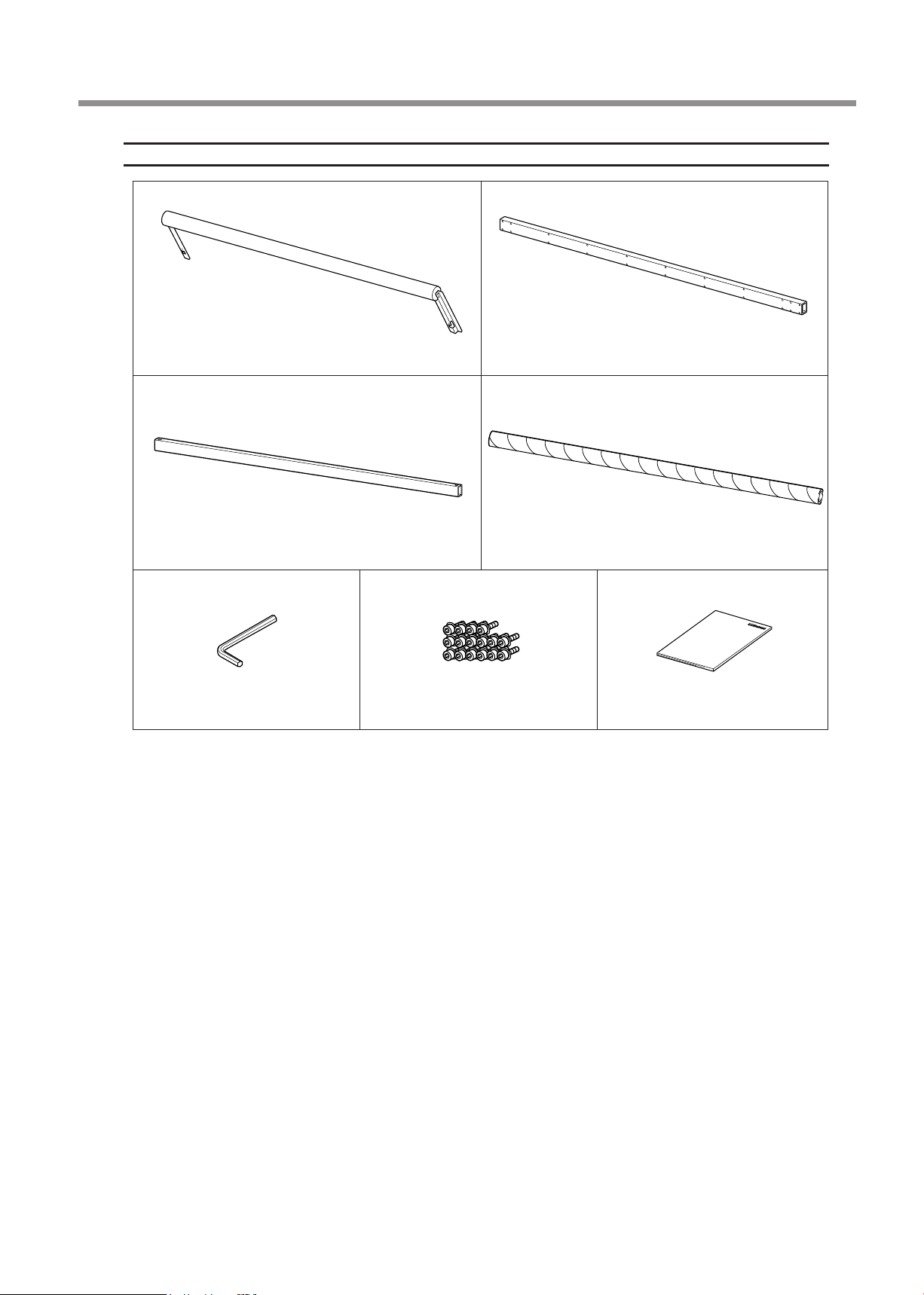
Rail and Accessories (TU2-74/64/54/42/30)
Dancer roller (1) Support bar (1)
2. Checking the Included Items
Rail slider (1) Paper tube (1)
Hex wrench (large) (1) Large bolts (16) User's manual (this document) (1)
13
Page 16
3. Assembling and Installing
Read This First
Before attempting the operations described here, rst install the printer you're using at the target loca-
tion.
Carry out the operations in a location that is at, level, and stable.
We recommend carrying out the operations at a location near to where the printer you're using is
installed.
Assembling and Installing
CAUTION
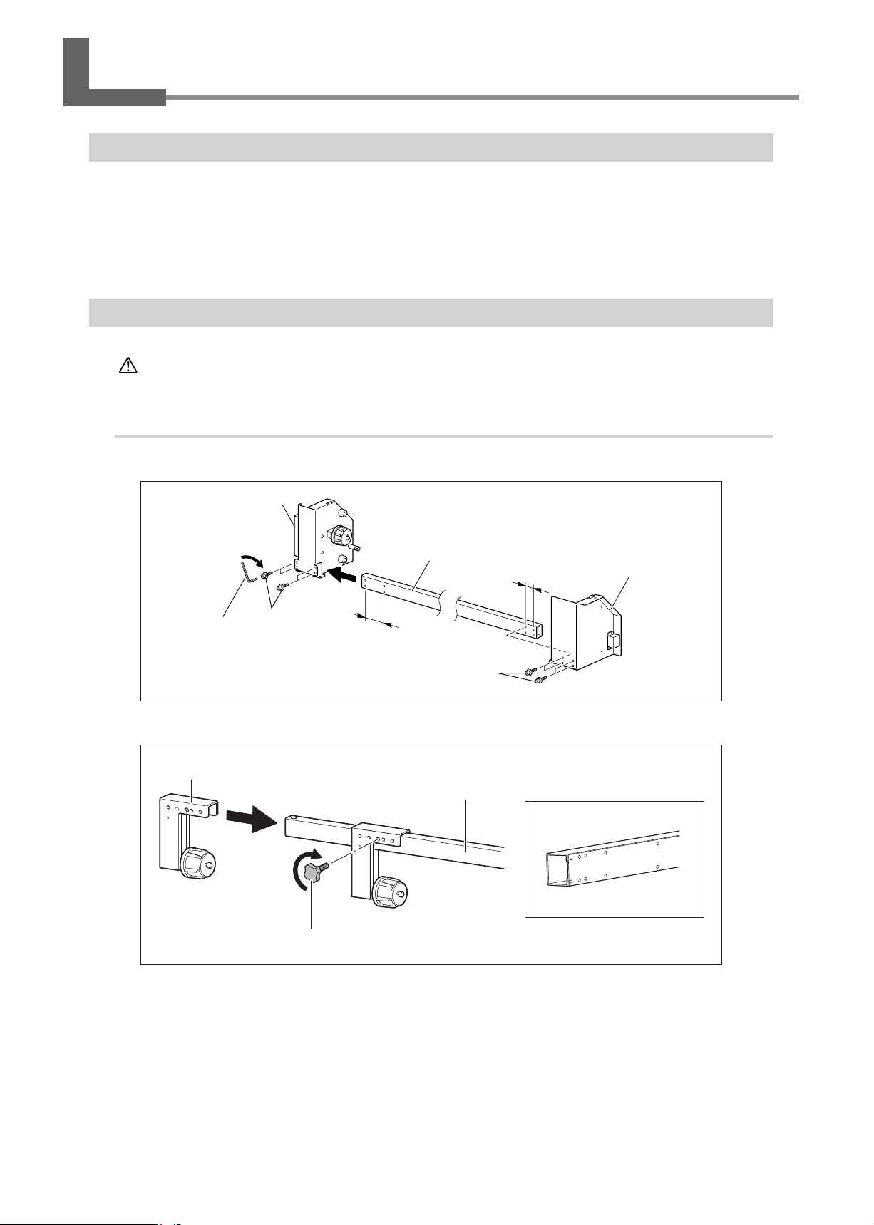
1.
Assemble the take-up unit.
Attach the frame and control box to the support bar.
Hex wrench
(large)
Attach the arm to the rail slider and secure in place with the arm retaining screw.
Arm
Unpacking and installation must be carried out by two or more persons.
Otherwise the machine or the stand may fall, resulting in injury.
Control box
4 pcs.
Large bolt
Wide
Support bar
Large bolts
Rail slider
Narrow
4 pcs.
Orient this side toward the rear.
Frame
14
Arm retaining screw
Page 17
3. Assembling and Installing
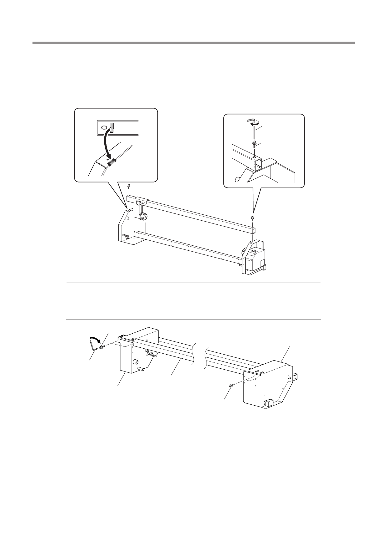
Place the rail slider on the control box and the frame and secure it in place.
Line up the tab on the frame with the slot in the rail slider, then use large bolts to secure it in place rst to the control
box, and then to the frame.
Line up the tab with the slot.
Bottom surface of the rail slider
slot
Slot
Tab
Hex wrench
(large)
Large bolt
Lay the unit on its side oriented as shown in the gure, then use large bolts to fasten the
control box and the frame to the support bar.
Large bolts
Frame
Hex wrench
(large)
Support bar
Control box
Large bolts
15
Page 18
3. Assembling and Installing
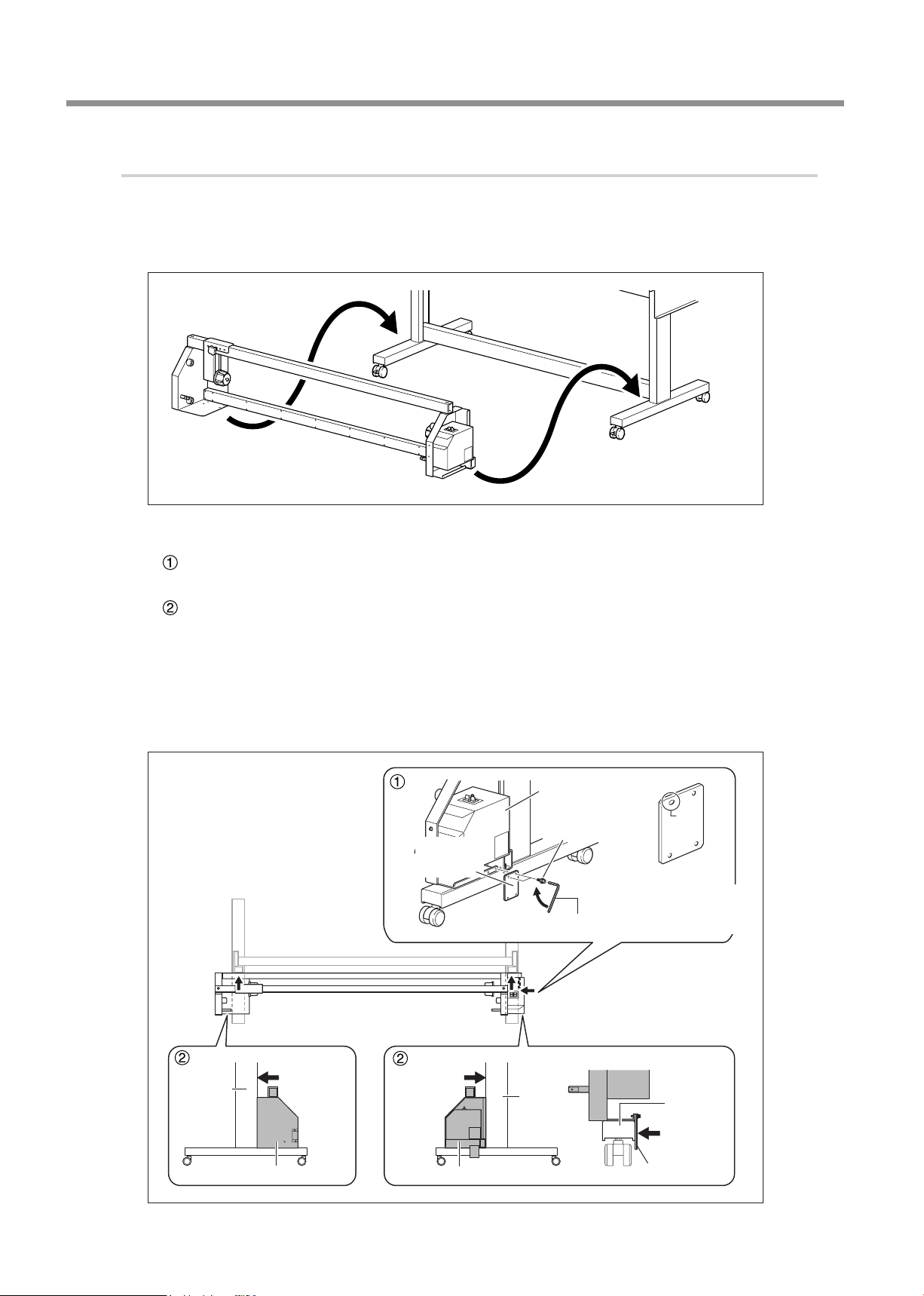
2.
Secure the assembled take-up unit in place on the printer stand.
Check to make sure the screws on the printer stand are not loose.
Retighten if loose.
Place the take-up unit on the stand.
Determine where to secure the take-up unit in place.
Secure mounting xture A in place using bolts with washers.
The mounting location varies according to the printer.
Make sure the take-up unit is completely ush with the stand.
Place so that the control box and frame are pressed against the stand leg and mounting xture A is pressed against
the caster.
TrueVIS series (VG-640,VG-540)
Attaching method of the VG-640, VG-540, refer to exhibit manual "Change notice for the user's manual contents".
PRO II/PRO II V series, SP-540V
Control box
Bolts with
washers
Mounting
xture A
Hex wrench (small)
Top
Slot
Bottom
Mounting xture A
The left and right sides
have no handedness.
16
Stand leg
Front side of the printer
Place
pressed
against.
Frame
Place
pressed
against.
Control box
Stand
leg
Caster
Place
pressed
against.
Mounting xture A
Page 19
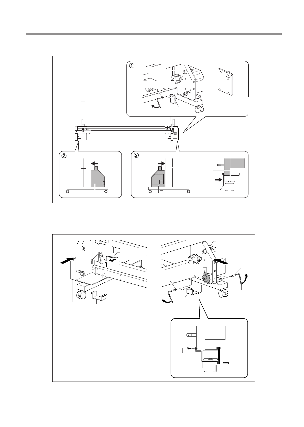
3. Assembling and Installing
Other Models (VS series, RS series, VP series, SP-300V/300, SP-540i/300i, RA-640, RE-640 etc.)
Stand leg
Frame
Bolts with washers
Hex wrench
(small)
Front side of the printer
Place
pressed
against.
Control box
Place
pressed
against.
Control box
Mounting
xture A
Stand leg
Place pressed
against.
Top
Slot
Bottom
Mounting xture A
The left and right sides
have no handedness.
Caster
Mounting
xture A
Attach mounting xtures B and C and secure the take-up unit to the stand.
Tighten the screws while holding the take-up unit pressed against the stand leg.
PRO II/PRO II V series, SP-540V
Press against
the stand leg.
Frame
Small bolts
Mounting xture C
Hex wrench
(small)
Bolts with
washers
Hex wrench
(small)
Mounting
xture A
Mounting
xture B
Bolt with
washer
Mounting
xture B
Control box
Press against
the stand leg.
Small bolts
Hex wrench
(small)
Small bolt
Mounting
xture A
17
Page 20
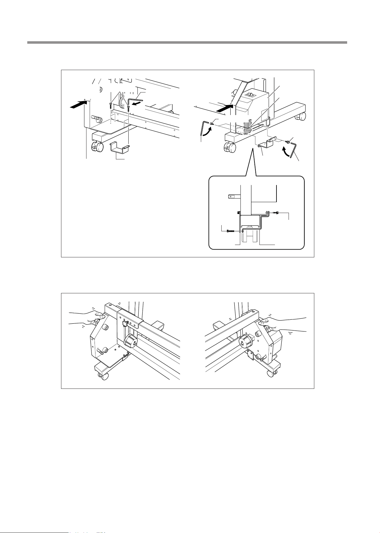
3. Assembling and Installing
Other Models (VS series, RS series, VP series, SP-300V/300, SP-540i/300i, RA-640, RE-640 etc.)
Press against
the stand leg.
Frame
Small bolts
Mounting xture C
Hex wrench
(small)
Press against
the stand leg.
Hex wrench
(small)
Small bolt
Mounting
xture A
Small bolts
Mounting
xture B
Control box
Mounting
xture A
Bolts with
washer
Hex wrench
(small)
Bolt with
washer
Mounting
xture B
After securing in place, hold the unit at the locations shown in the gure, apply gentle pressure, and make sure the
assembly is free of looseness. If looseness is present, again press the take-up unit against the stand leg and caster
and tighten the small bolts.
18
Page 21
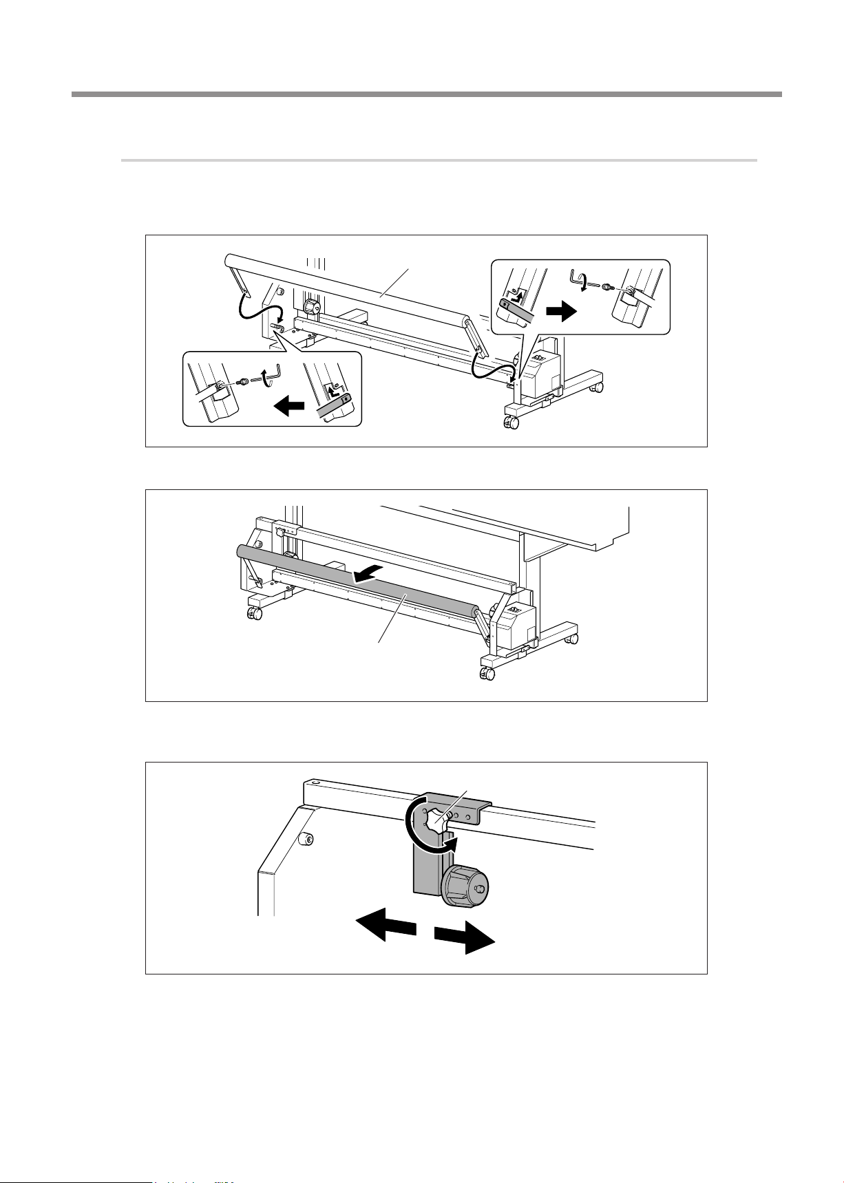
3.
Attach the dancer roller and mount the paper tube.
Attach the dancer roller.
Working from the right side rst, secure in place.
Dancer roller
Line up with the
bolt hole and
secure in place.
3. Assembling and Installing
Line up with the bolt hole
and secure in place.
Pull the dancer roller back toward you.
Dancer roller
Loosen the arm adjustment screw.
Loosen the screw just enough to allow the arm to move left and right.
Arm retaining screw
19
Page 22
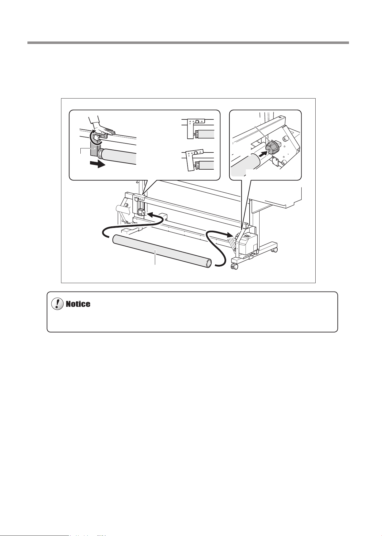
3. Assembling and Installing
Attach the end caps to the paper tube and secure the arm in place.
First, t the paper tube securely onto the end cap on the same side as the right stand leg. Next, press the end cap on
the same side as the arm into the paper tube and securely t the end cap into the paper tube. Finally, secure the arm
in place using the arm retaining screw.
Tighten the screw
while pressing down
from above.
Arm
Fit onto this securely.
End cap
OK
Paper
tube
Not
OK
Fit onto this securely.
Paper tube
For the paper tube, use the included item. Using something other than the included item may result in spinning without
traction or other problems that impede media take-up.
20
Page 23
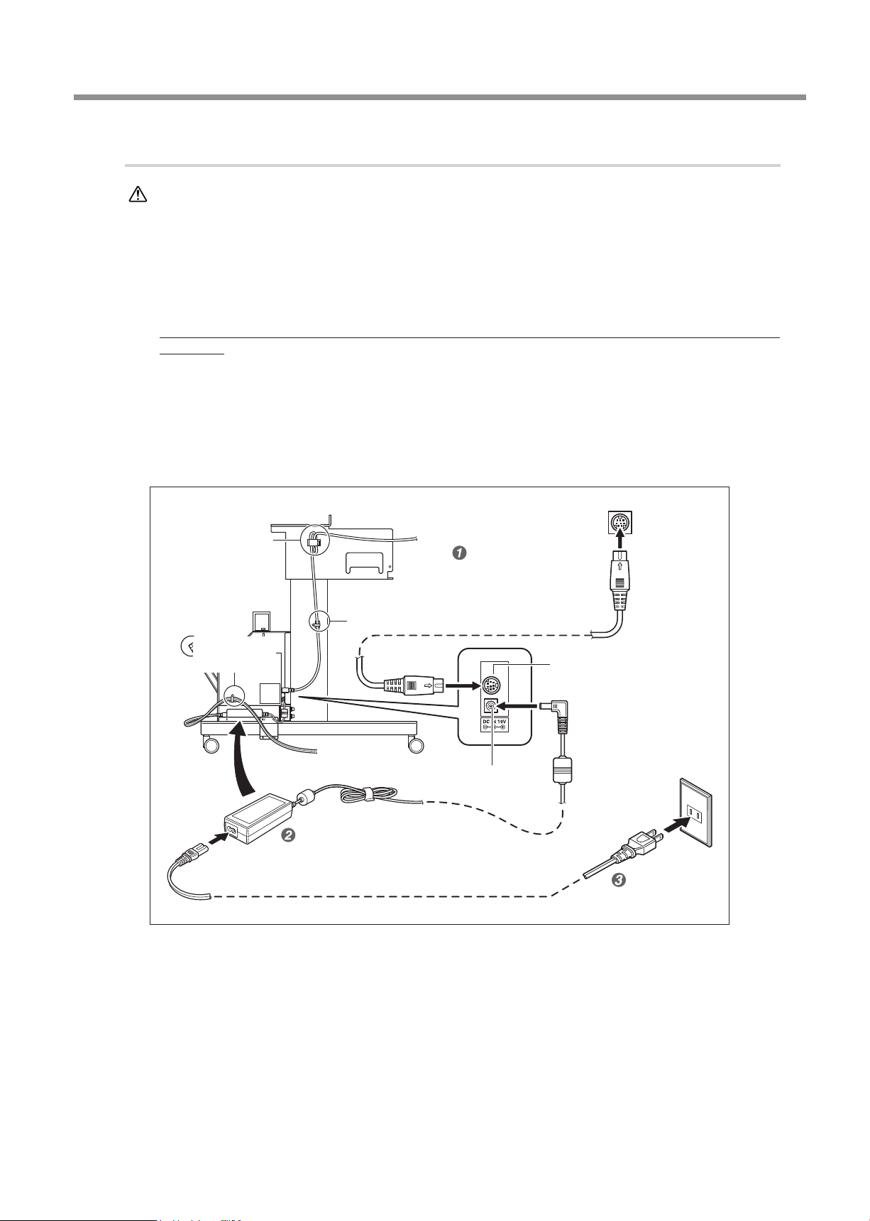
4.
Connect the cables.
3. Assembling and Installing
WARNING
Insert the printer connector cable into the printer connector and connect the other end to
Connect to electrical outlet that complies with this machine's ratings (for voltage,
frequency, and current).
Incorrect voltage or insufcient current may cause re or electrical shock.
the printer.
Ax large and small cable clamps at the locations shown in the gure and secure the cables in place. Bundle excess
cable into the large cable clamp.
If you're using a PRO II/PRO II V series or SP series (except SP-540i and 300i) printer, this cable connection is not
necessary.
Place the AC adapter at the location shown in the gure and connect it to the AC adapter
jack.
Connect the power cord.
Ax a small cable clamp at the location shown in the gure and secure the power cord in place.
Printer connector (*1)
Cable clamp
(large)
Printer connector cable
After connecting this cable,
connect the AC adapter.
Cable clamp (small)
Cable clamp
(small)
Place inside the
control box.
AC adaptor
(*1) The position of the printer connector diers depending on the model. On the VG series, the connector is located on
the front of the printer, below the heater. On the VS series, the connector is located on the back of the printer, close to
the power supply.
AC adaptor jack
Printer connector
Electrical outlet
Power cord
21
Page 24
4. Operation
Operating Conditions for the Take-up Unit
Never pull the media with excessive force.
Pulling the media with excessive force may actuate the protective feature and result in an error. To avoid pulling the media
with excessive force, be sure to observe the following points.
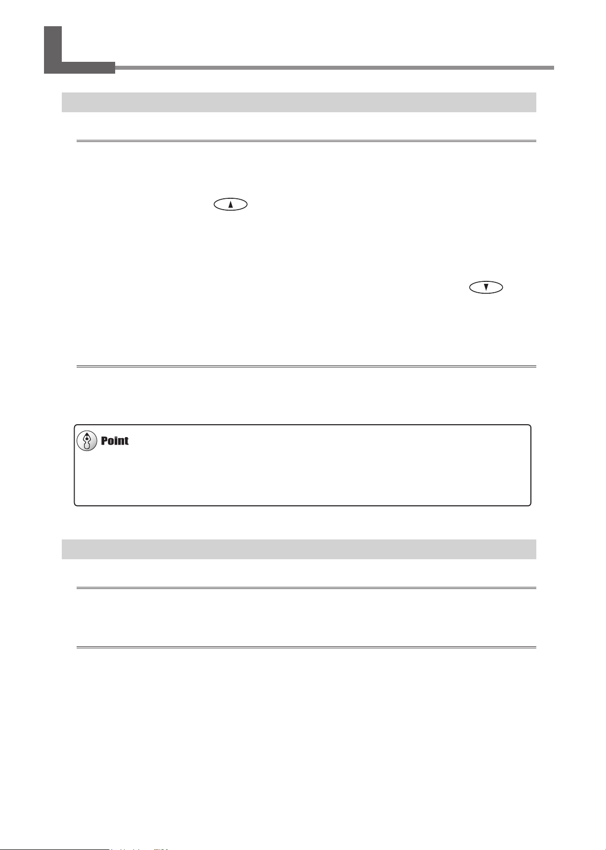
Never operate the MANUAL switch for the take-up unit when the loading lever is engaged (lowered).
Never use the cursor key ( ) to feed the media in reverse.
Media may pulled by excessive force and result in an error.
If the printer is provided with a cutting feature, be sure to observe the following points as well. These are all intended to
avoid pulling the media with excessive force.
Never perform cutting operations.
When feeding out media toward the front of the machine by pressing the cursor key ( ) , be
sure to set the base point.
Set the [PREFEED] setting-menu item to "DISABLE."
If a [FEED FOR DRY] menu item is available, set it to "DISABLE."
Never use the automatic-cutoff feature for media.
When the setting to execute automatic cuto of the media is made on the computer, media cuto is performed when
printing of one page nishes. When you're performing continuous printing and take-up for two or more pages, turn o the
automatic-cuto feature on the computer. Take-up quits as soon as the media is cut o.
For those who use the VS-series printers:
With the machines of the VS series, you can perform cutting operations by selecting [TU2] from the [SETUP SHEET]
menu. (Refer to the procedure
User’s Manual for the VS series, “Using Media Take-up System“ in “Chapter 4 Part of Practice“
1.-
in P. 23, "How to Load Media").
About the Paper Tube
For the paper tube, use the included item.
The included paper tube is a special part exclusively for use with this machine. Using something other than the included
item may result in spinning without traction or other problems that impede media take-up.
The paper tube is a part that wears out.
22
The replacement cycle varies according to usage conditions, but to ensure good media take-up, monitor the state of the
paper tube and replace it when necessary. To purchase a replacement, contact your authorized Roland DG Corp. dealer.
Page 25
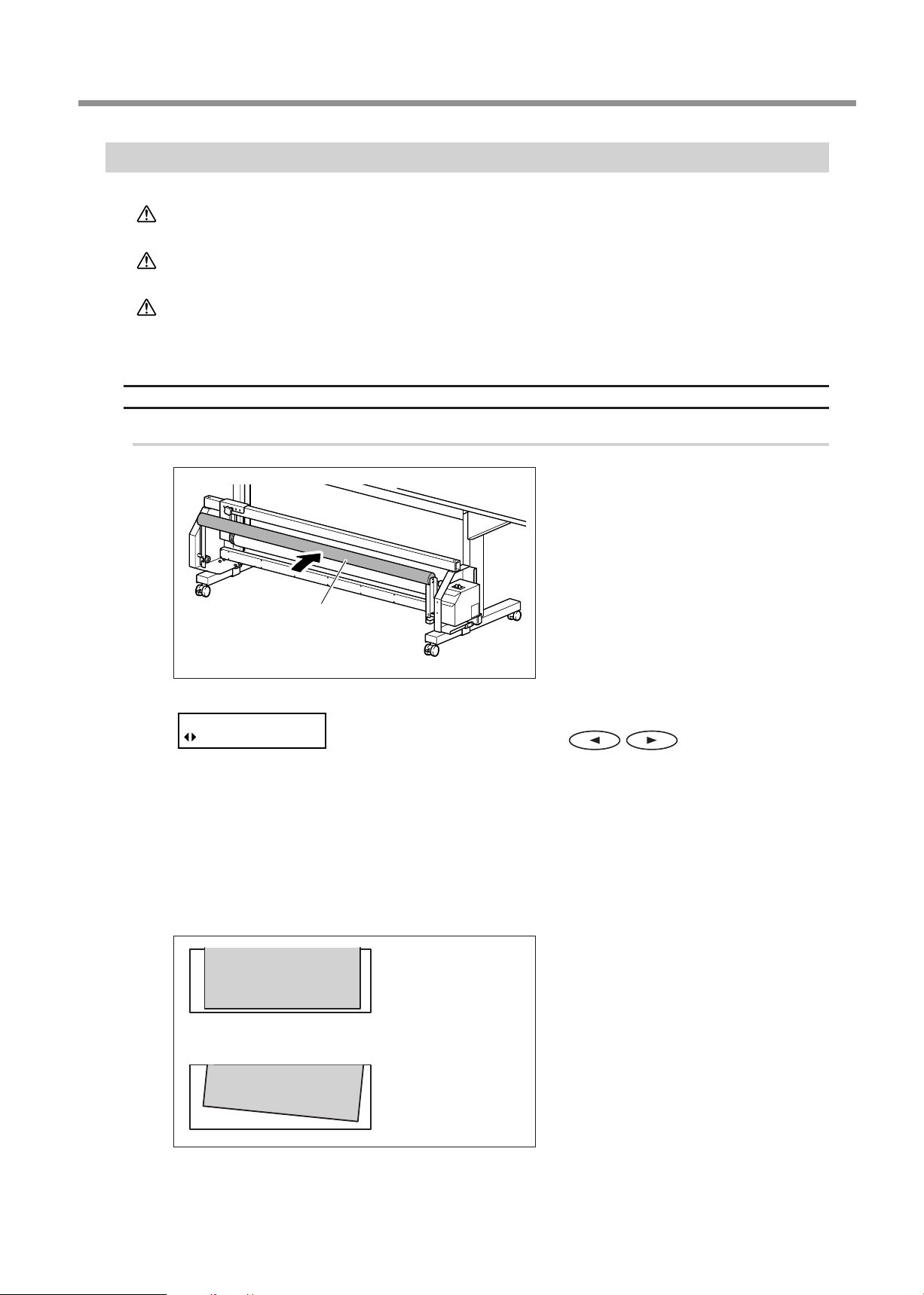
How to Load Media
SETUP SHEET
TU
4. Operation
CAUTION
CAUTION
CAUTION
VG series,VS series, RS series, VP series, SP-540i/300i, RA-640, RE-640
1.
Pass the media through the printer.
Load roll media correctly.
Otherwise the media may fall and cause injury.
Roll media weighs about 30 kg (66 lb.). To avoid injury, handle with care.
Never load media that weighs more than 30 kg (66 lb.).
The printer may fail to withstand the weight and topple over, or the media may fall
from the unit.
Move the dancer roller toward the
rear.
Dancer roller
VP series, RS series, SP-540i/300i, RA-640, RE-640 or when selecting [TU] with VG
series, VS series:
Make sure the printer's [PREFEED] and [FEED FOR DRY] menu items are each set to
"DISABLE." (For RS series, RA-640 and RE-640, check [FEED FOR DRY] only.)
For information on how to check or change setting values, refer to the user's manual for the printer.
Switch on the printer's sub power, and when the screen shown
in the gure appears, press
companying the pull-back operation) or [TU] (not accompanying
the pull-back operation).
[TU2] is available only when you’re using the VS series printer.
Load roll media onto the printer, then
lower the loading lever.
OK
Not
For information on how to perform loading, refer
to the user's manual for the printer.
After loading, check the following points.
The media is loaded straight.
All areas of the media are taut.
If the media is slack or crooked, raise the loading
lever and reload the media.
to select [TU2] (ac-
OK
23
Page 26
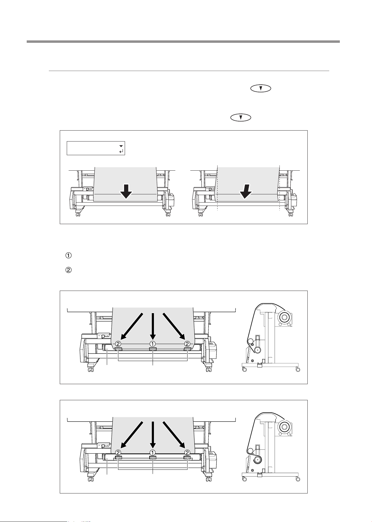
4. Operation
2.
Fasten the media to the paper tube.
Make sure the screen shown in the gure is displayed, then use
dia until its leading
out straight at this time.
If the media is not straight, redo the loading operation.
You can adjust the length of the media in 10-millimeter steps by pressing
hold down the key. )
LOAD SHEET
TO TAKE-UP
Using adhesive tape, fasten the center and side edges of the media to the paper tube
(fasten a total of three locations).
Secure the center of the media in place while keeping the media stretched taut to keep
it free of slack.
While pulling the media from the center outward, fasten the left and right edges.
edge reaches the paper tube. Check to make sure the media is pulled
OK
(To pull out media continuously,
to pull out the me-
Not
OK
Take-up with outward curl
Paper tube
Take-up with inward curl
Adhesive tape
24
Paper tube
Adhesive tape
Page 27
4. Operation
TILT DANCER
ROLLER TO FRONT
Pull the dancer roller back toward you, then make sure the media is stretched taut, and
press
The screen shown in the gure appears.
3.
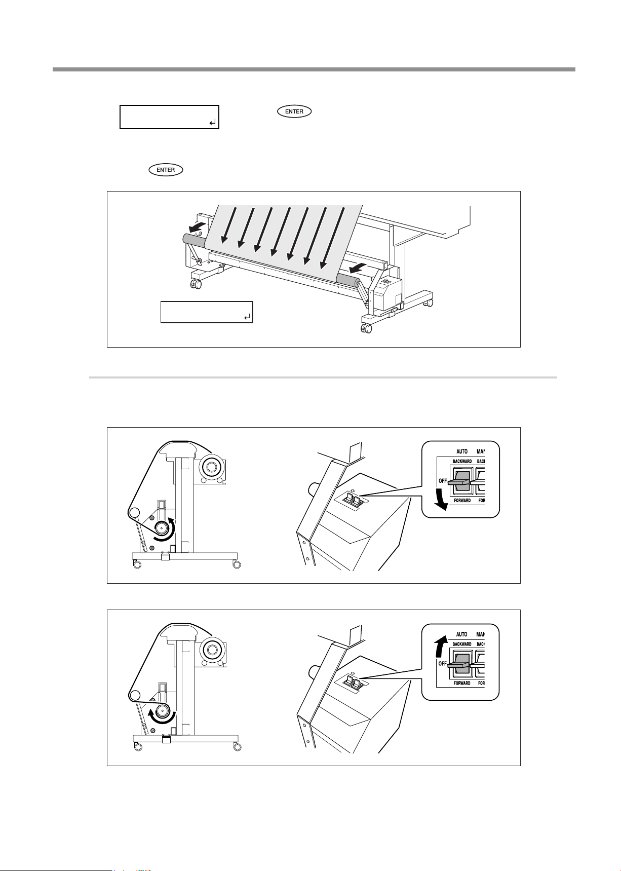
Take up the media.
Make the setting for the AUTO switch on the take-up unit.
Take-up with outward curl
.
CHECK
TAKE-UP SETTING
Press .
The media is pulled out and the screen shown in the gure appears.
Take-up with inward curl
25
Page 28
4. Operation
W1200mm
When you begin take-up, take care to ensure that the end of the media does not become rolled or
creased.
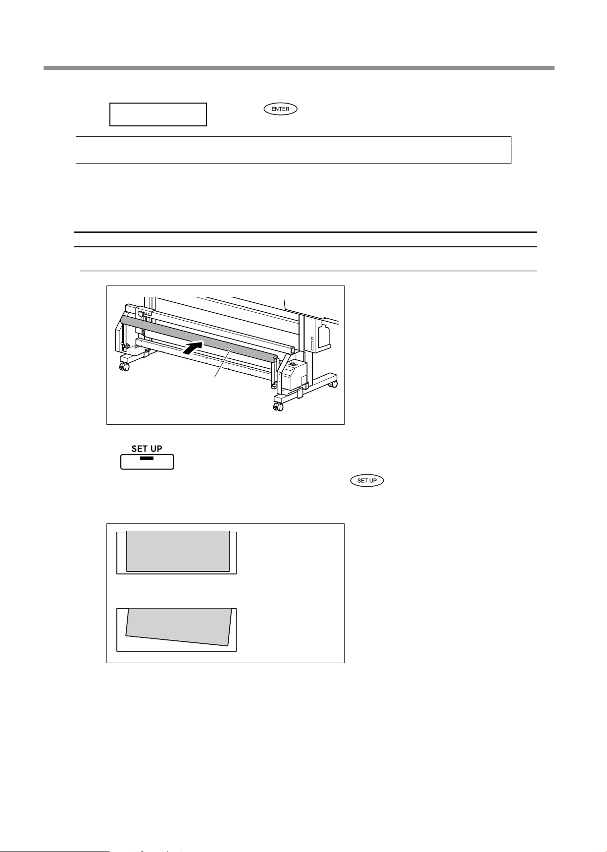
This completes loading of the media.
PRO II/PRO II V series, SP series (except SP-540i and 300i)
1.
Pass the media through the printer.
Dancer roller
Press .
The screen shown in the gure appears.
Move the dancer roller toward the
rear.
Steadily lighted
OK
Load roll media onto the printer and put
the printer in the setup state (so that
is illuminated).
For information on how to perform loading, refer
to the user's manual for the printer.
After loading, check the following points.
The media is loaded straight.
All areas of the media are taut.
If the media is slack or crooked, cancel the setup
state and reload the media.
Not
OK
Check to make sure the following setting-menu items on the printer are each set to "DIS-
ABLE."
The [PREFEED] setting-menu item
The [FEED FOR DRY] setting-menu item (only on models where this setting is available)
For information on how to check or change setting values, refer to the user's manual for the printer.
26
Page 29
4. Operation
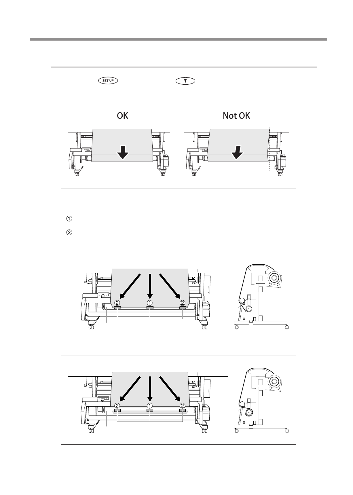
2.
Fasten the media to the paper tube.
Make sure is lighted, then use to pull out the media until its leading edge
reaches the paper tube. Check to make sure the media is pulled out straight at this time.
If the media is not straight, redo the loading operation.
Using adhesive tape, fasten the center and side edges of the media to the paper tube
(fasten a total of three locations).
Secure the center of the media in place while keeping the media stretched taut to keep
it free of slack.
While pulling the media from the center outward, fasten the left and right edges.
Take-up with outward curl
Paper tube
Take-up with inward curl
Adhesive tape
Paper tube
Adhesive tape
27
Page 30
4. Operation
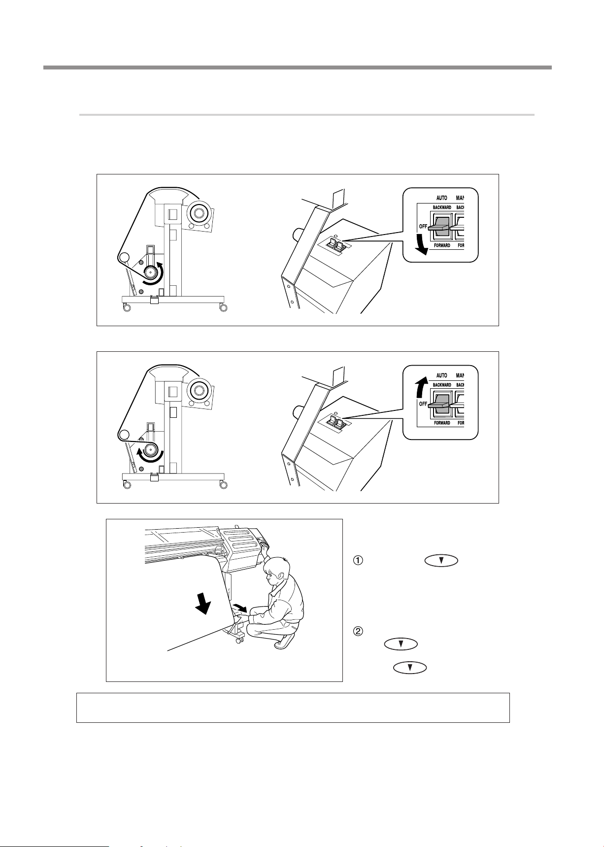
3.
Take up the media.
Make the setting for the AUTO switch on the take-up unit.
Take-up with outward curl
Take-up with inward curl
While supporting the dancer roller
feed out media and take it up on the
paper tube.
While using to feed out the
media a little at a time, pull the dancer
roller back toward you, stopping at a
place where the dancer roller doesn't
go back into the machine when you
let go of it.
Let go of the dancer roller, then
press
up unit starts to perform take-up,
release
again. When the take-
.
28
When you begin take-up, take care to ensure that the end of the media does not become rolled or
creased.
Page 31
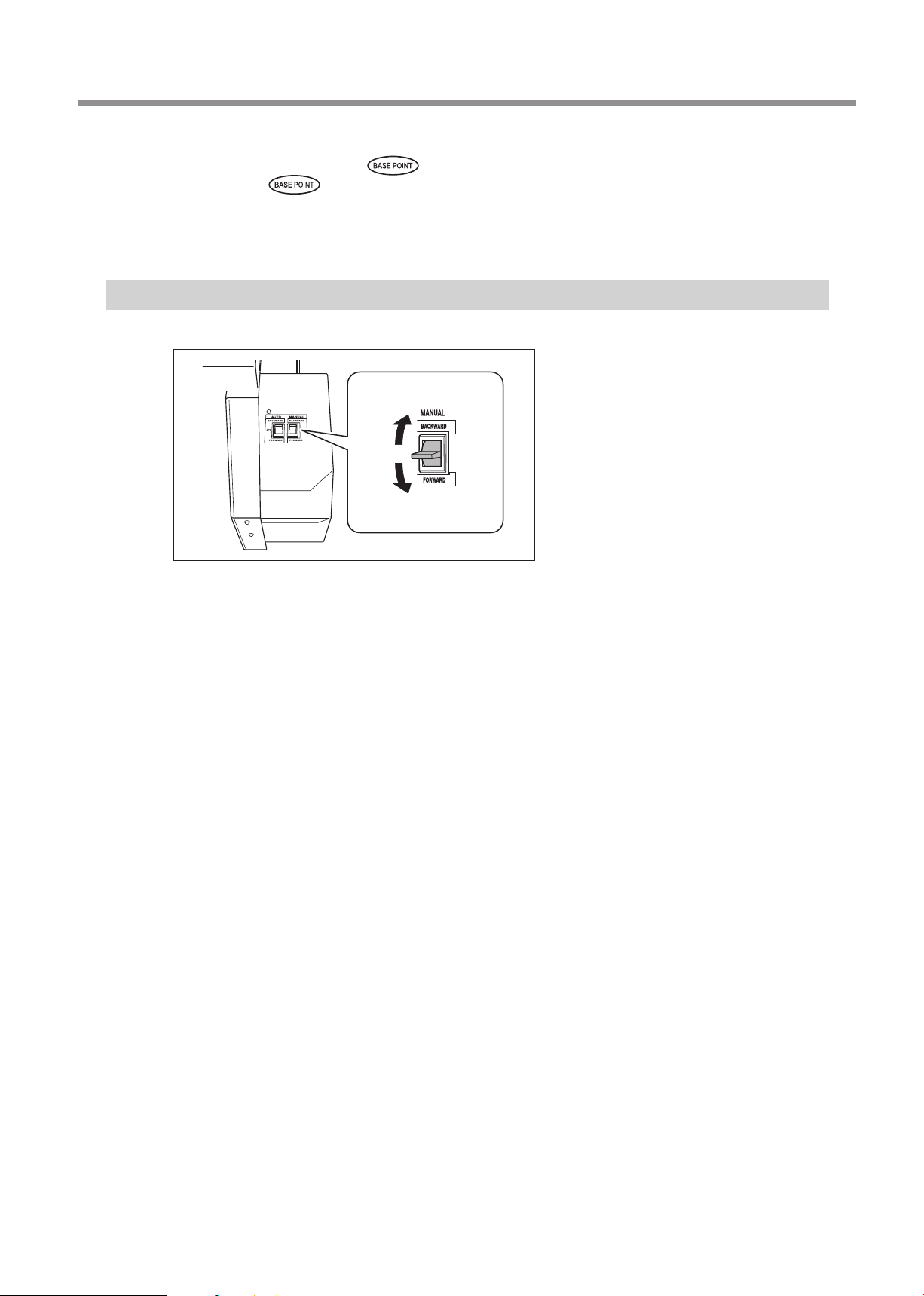
Press BASE POINT key ( ).
Be sure to press and set the base point (the output-start location). Attempting to start printing with the
base point left unset causes the media to be taken up with excessive force and results in a motor error.
This completes loading of the media.
To Take Up Media Manually
Take-up with inward
curl
Take-up with outward
curl
4. Operation
You can take up media by using the MANUAL
switch.
However, never operate the MANUAL switch
while the loading lever is engaged (lowered).
Doing so may cause the media to be pulled with
excessive force, actuating the protective feature
and resulting in an error.
29
Page 32
4. Operation
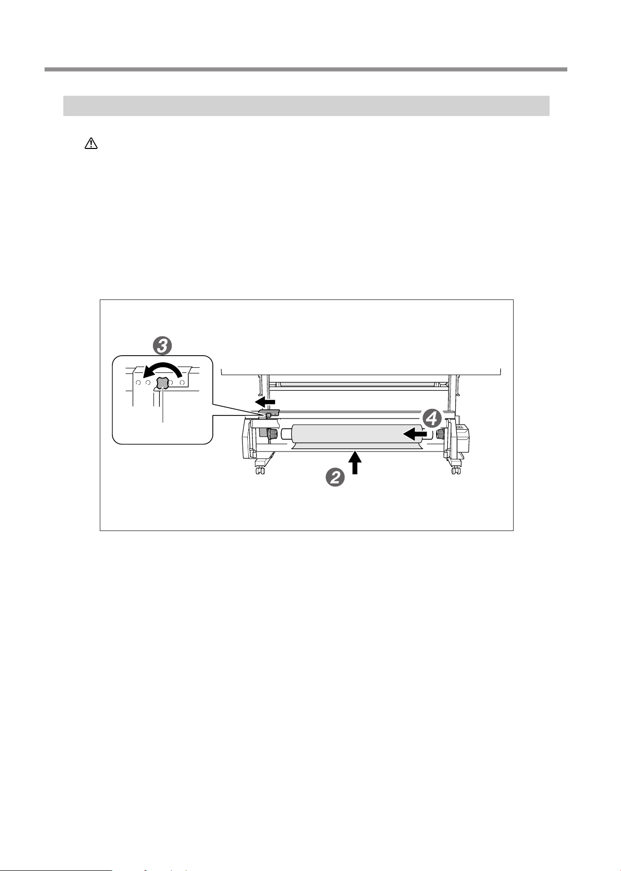
How to Remove Taken-up Media
CAUTION
Cut off the media.
For more information about how to perform cuto, refer to the user's manual included with the printer.
Support the paper tube to prevent it from falling.
Loosen the retaining screw and move the arm.
Detach the paper tube from the end caps.
Arm retaining screw
Removal of taken-up roll media from the unit is a task which must be carried out
by two or more persons.
If dropped, such items may cause injury.
30
Page 33

5. What to do if...
The Take-up Unit Doesn't Take Up Media.
Are the power cord and AC adapter connected correctly?
Connect securely, so that the connection will not come loose or be incomplete.
Is the AUTO switch set to [OFF]?
Set the AUTO switch to match the direction of take-up.
Is the setting for the AUTO switch at the correct position?
Orient the setting of the AUTO switch to match the direction of take-up for the media.
Is automatic cutoff of the media being performed?
Take-up quits as soon as the media is cut o. On the computer (the software RIP), make the setting so that the printer doesn't
perform automatic cuto. For more information about the setting for automatic cuto, refer to the documentation for the
software RIP.
Is the paper tube installed correctly?
Securely insert the paper tube onto the end caps. If the paper tube is not attached correctly, it may spin without traction
and fail to take up the media.
P. 20, "Assembling and Installing" Procedure 3.-
Is the paper tube bent or sagging?
Media cannot be taken up smoothly when the paper tube is bent or sagging.
Are you using the included paper tube?
For the paper tube, use the included item. Using something other than the included item may result in spinning without
traction or other problems that impede media take-up.
P. 22, "About the Paper Tube"
Media Take-up Is Not Straight.
Is the media loaded correctly?
Remove the media, then redo media loading from the beginning.
31
Page 34
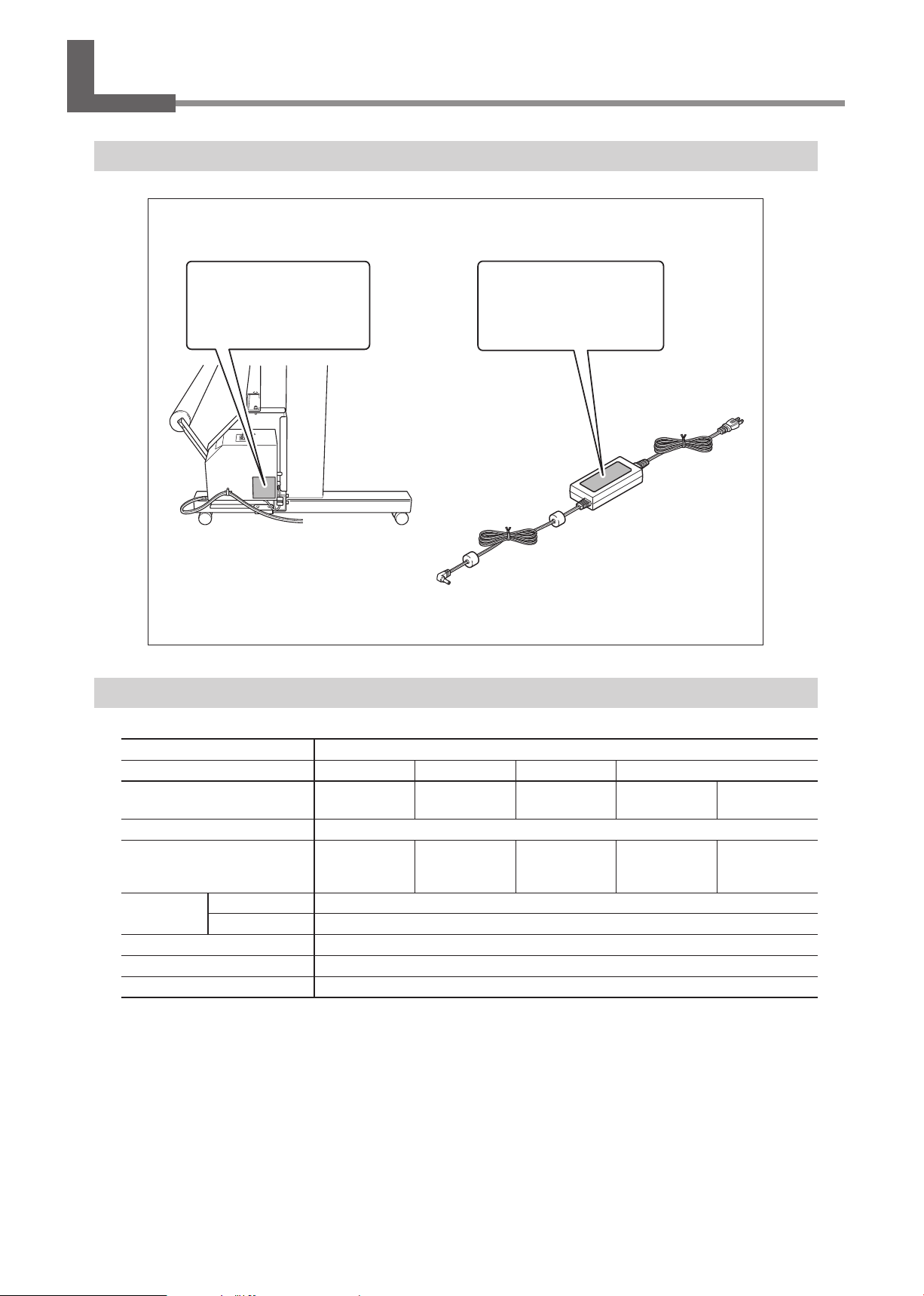
6. Appendix
Locations of the Power Rating and Serial Number Labels
Serial Number
This is required when you seek
maintenance, servicing, or support. Never peel o the label or let
it get dirty.
Specications
Power Rating
Use an electrical outlet that meets
the requirements for voltage,
frequency, and amperage given
here.
TUC-2
Rail and Accessaries TU2-74 TU2-64 TU2-54 TU2-42 TU2-30
Acceptable media widths
Acceptable media weights
Weight
(Total including control box,
rail, and accessories)
Power
requirements
Power consumption
Acoustic noise level
Environmental
(*)
NOTE: The actual usable media weight may depend on the printer's conditions for usable media.
Dedicated AC adapter
Machine
Less than 1,879
mm(74 in.)
26.5 kg
(58.4 lb.)
AC 100 to 240 V ± 10% 50/60 Hz
DC 19 V 2.1 A
Approx. 20 W
64 dB (A) or less
Temperature: 5 to 40ºC (41 to 104ºF), humidity: 20 to 80%RH (non-condensing)
Less than 1,625
mm(64 in.)
25 kg
(55.1 lb.)
Less than 1,371
mm(54 in.)
Maximum 30 kg (*)
22 kg
(48.5 lb.)
Less than 1,071
mm(42 in.)
20.5 kg
(45.2 lb.)
Less than 762
mm(30 in.)
18.5 kg
(40.8 lb.)
32
Page 35
Page 36
 Loading...