

Page 1
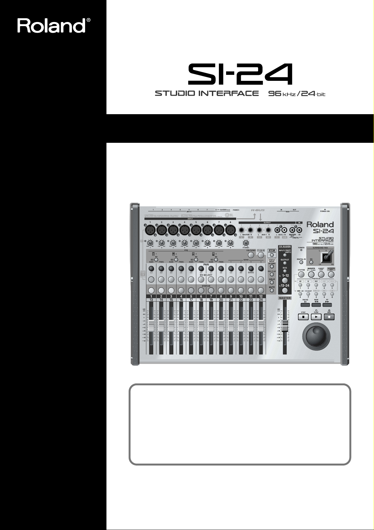
Owner’s Manual
Before using this unit, carefully read the sections entitled: “IMPORTANT
SAFETY INSTRUCTIONS” (Owner’s Manual p. 2), “USING THE UNIT
SAFELY” (Owner’s Manual p. 3), and “IMPORTANT NOTES” (Owner’s
Manual p. 5). These sections provide important information concerning the
proper operation of the unit. Additionally, in order to feel assured that you
have gained a good grasp of every feature provided by your new unit,
Owner’s Manual should be read in its entirety. The manual should be saved
and kept on hand as a convenient reference.
Copyright © 2002 ROLAND CORPORATION
All rights reserved. No part of this publication may be reproduced in any form without the
written permission of ROLAND CORPORATION.
Roland Web Site http://www.roland.co.jp/
Page 2
CAUTION
RISK OF ELECTRIC SHOCK
DO NOT OPEN
ATTENTION: RISQUE DE CHOC ELECTRIQUE NE PAS OUVRIR
CAUTION: TO REDUCE THE RISK OF ELECTRIC SHOCK,
DO NOT REMOVE COVER (OR BACK).
NO USER-SERVICEABLE PARTS INSIDE.
REFER SERVICING TO QUALIFIED SERVICE PERSONNEL.
The lightning flash with arrowhead symbol, within an
equilateral triangle, is intended to alert the user to the
presence of uninsulated “dangerous voltage” within the
product’s enclosure that may be of sufficient magnitude to
constitute a risk of electric shock to persons.
The exclamation point within an equilateral triangle is
intended to alert the user to the presence of important
operating and maintenance (servicing) instructions in the
literature accompanying the product.
INSTRUCTIONS PERTAINING TO A RISK OF FIRE, ELECTRIC SHOCK, OR INJURY TO PERSONS.
IMPORTANT SAFETY INSTRUCTIONS
SAVE THESE INSTRUCTIONS
WARNING - When using electric products, basic precautions should always be followed, including the following:
1. Read these instructions.
2. Keep these instructions.
3. Heed all warnings.
4. Follow all instructions.
5. Do not use this apparatus near water.
6. Clean only with a dry cloth.
7. Do not block any of the ventilation openings. Install in
accordance with the manufacturers instructions.
8. Do not install near any heat sources such as radiators,
heat registers, stoves, or other apparatus (including
amplifiers) that produce heat.
9. Do not defeat the safety purpose of the polarized or
grounding-type plug. A polarized plug has two blades with
one wider than the other. A grounding type plug has two
blades and a third grounding prong. The wide blade or the
third prong are provided for your safety. When the provided
plug does not fit into your outlet, consult an electrician for
replacement of the obsolete outlet.
WARNING:
IMPORTANT:
As the colours of the wires in the mains lead of this apparatus may not correspond with the coloured markings identifying
the terminals in your plug, proceed as follows:
The wire which is coloured GREEN-AND-YELLOW must be connected to the terminal in the plug which is marked by the
letter E or by the safety earth symbol or coloured GREEN or GREEN-AND-YELLOW.
The wire which is coloured BLUE must be connected to the terminal which is marked with the letter N or coloured BLACK.
The wire which is coloured BROWN must be connected to the terminal which is marked with the letter L or coloured RED.
THIS APPARATUS MUST BE EARTHED
THE WIRES IN THIS MAINS LEAD ARE COLOURED IN ACCORDANCE WITH THE FOLLOWING CODE.
GREEN-AND-YELLOW: EARTH, BLUE: NEUTRAL, BROWN: LIVE
10. Protect the power cord from being walked on or pinched
particularly at plugs, convenience receptacles, and the
point where they exit from the apparatus.
11. Only use attachments/accessories specified by the
manufacturer.
12. Never use with a cart, stand, tripod, bracket,
or table except as specified by the
manufacturer, or sold with the apparatus.
When a cart is used, use caution when
moving the cart/apparatus combination to
avoid injury from tip-over.
13. Unplug this apparatus during lightning storms or when
unused for long periods of time.
14. Refer all servicing to qualified service personnel. Servicing
is required when the apparatus has been damaged in any
way, such as power-supply cord or plug is damaged, liquid
has been spilled or objects have fallen into the apparatus,
the apparatus has been exposed to rain or moisture, does
not operate normally, or has been dropped.
For the U.K.
2
Page 3
USING THE UNIT SAFELY
Used for instructions intended to alert
the user to the risk of death or severe
injury should the unit be used
improperly.
Used for instructions intended to alert
the user to the risk of injury or material
damage should the unit be used
improperly.
* Material damage refers to damage or
other adverse effects caused with
respect to the home and all its
furnishings, as well to domestic
animals or pets.
001
• Before using this unit, make sure to read the
instructions below, and the Owner’s Manual.
..........................................................................................................
002a
• Do not open or perform any internal modifications on the unit.
..........................................................................................................
003
• Do not attempt to repair the unit, or replace parts
within it (except when this manual provides
specific instructions directing you to do so). Refer
all servicing to your retailer, the nearest Roland
Service Center, or an authorized Roland
distributor, as listed on the “Information” page.
..........................................................................................................
004
• Never use or store the unit in places that are:
• Subject to temperature extremes (e.g., direct
sunlight in an enclosed vehicle, near a heating
duct, on top of heat-generating equipment); or
are
• Damp (e.g., baths, washrooms, on wet floors);
or are
• Humid; or are
• Exposed to rain; or are
• Dusty; or are
• Subject to high levels of vibration.
..........................................................................................................
007
• Make sure you always have the unit placed so it is
level and sure to remain stable. Never place it on
stands that could wobble, or on inclined surfaces.
..........................................................................................................
008a
• The unit should be connected to a power supply
only of the type described in the operating instructions, or as marked on the bottom of unit.
..........................................................................................................
008e
• Use only the attached power-supply cord.
..........................................................................................................
The symbol alerts the user to important instructions
or warnings.The specific meaning of the symbol is
determined by the design contained within the
triangle. In the case of the symbol at left, it is used for
general cautions, warnings, or alerts to danger.
The symbol alerts the user to items that must never
be carried out (are forbidden). The specific thing that
must not be done is indicated by the design contained
within the circle. In the case of the symbol at left, it
means that the unit must never be disassembled.
The ● symbol alerts the user to things that must be
carried out. The specific thing that must be done is
indicated by the design contained within the circle. In
the case of the symbol at left, it means that the powercord plug must be unplugged from the outlet.
009
• Do not excessively twist or bend the power cord,
nor place heavy objects on it. Doing so can
damage the cord, producing severed elements and
short circuits. Damaged cords are fire and shock
hazards!
..........................................................................................................
010
• This unit, either alone or in combination with an
amplifier and headphones or speakers, may be
capable of producing sound levels that could
cause permanent hearing loss. Do not operate for
a long period of time at a high volume level, or at
a level that is uncomfortable. If you experience
any hearing loss or ringing in the ears, you should
immediately stop using the unit, and consult an
audiologist.
..........................................................................................................
011
• Do not allow any objects (e.g., flammable material,
coins, pins); or liquids of any kind (water, soft
drinks, etc.) to penetrate the unit.
..........................................................................................................
013
• In households with small children, an adult
should provide supervision until the child is
capable of following all the rules essential for the
safe operation of the unit.
..........................................................................................................
014
• Protect the unit from strong impact.
(Do not drop it!)
..........................................................................................................
015
• Do not force the unit’s power-supply cord to share
an outlet with an unreasonable number of other
devices. Be especially careful when using
extension cords—the total power used by all
devices you have connected to the extension
cord’s outlet must never exceed the power rating
(watts/amperes) for the extension cord. Excessive
loads can cause the insulation on the cord to heat
up and eventually melt through.
..........................................................................................................
3
Page 4
016
• Before using the unit in a foreign country, consult
with your retailer, the nearest Roland Service
Center, or an authorized Roland distributor, as
listed on the “Information” page.
..........................................................................................................
101a
• The unit should be located so that its location or
position does not interfere with its proper ventilation.
..........................................................................................................
102b
• Always grasp only the plug on the power-supply
cord when plugging into, or unplugging from, an
outlet or this unit.
..........................................................................................................
104
• Try to prevent cords and cables from becoming
entangled. Also, all cords and cables should be
placed so they are out of the reach of children.
..........................................................................................................
106
• Never climb on top of, nor place heavy objects on
the unit.
..........................................................................................................
107b
• Never handle the power cord or its plugs with wet
hands when plugging into, or unplugging from,
an outlet or this unit.
..........................................................................................................
108a
• Before moving the unit, disconnect the power
plug from the outlet, and pull out all cords from
external devices.
..........................................................................................................
109a
• Before cleaning the unit, turn off the power and
unplug the power cord from the outlet (Refer to
"Turning the power off" p. 16).
..........................................................................................................
110a
• Whenever you suspect the possibility of lightning
in your area, pull the plug on the power cord out
of the outlet.
..........................................................................................................
118
• Should you remove a ground screw, make sure to
put them in a safe place out of children's reach, so
there is no chance of them being swallowed
accidentally.
..........................................................................................................
• Avoid using the unit immediately after it has been
moved to a location with a level of temperature
and humidity that is greatly different than its
former location. Rapid changes in the
environment can cause condensation to form
inside the unit, which will adversely affect the
operation of the unit and/or damage it. When the
unit has been moved, allow it to become accustomed to the new environment (allow a few
hours) before operating it.
..........................................................................................................
4
Page 5

IMPORTANT NOTES
291b
In addition to the items listed under “IMPORTANT SAFETY INSTRUCTIONS” and “USING THE UNIT SAFELY” on pages 2
and 3–4, please read and observe the following:
Power Supply
301
• Do not use this unit on the same power circuit with any
device that will generate line noise (such as an electric
motor or variable lighting system).
307
• Before connecting this unit to other devices, turn off the
power to all units. This will help prevent malfunctions
and/or damage to speakers or other devices.
Placement
351
• Using the unit near power amplifiers (or other equipment
containing large power transformers) may induce hum.
To alleviate the problem, change the orientation of this
unit; or move it farther away from the source of interference.
352a
• This device may interfere with radio and television
reception. Do not use this device in the vicinity of such
receivers.
352b
• Noise may be produced if wireless communications
devices, such as cell phones, are operated in the vicinity of
this unit. Such noise could occur when receiving or initiating a call, or while conversing. Should you experience
such problems, you should relocate such wireless devices
so they are at a greater distance from this unit, or switch
them off.
354a
• Do not expose the unit to direct sunlight, place it near
devices that radiate heat, leave it inside an enclosed
vehicle, or otherwise subject it to temperature extremes.
Excessive heat can deform or discolor the unit.
355
• To avoid possible breakdown, do not use the unit in a wet
area, such as an area exposed to rain or other moisture.
Maintenance
401a
• For everyday cleaning wipe the unit with a soft, dry cloth
or one that has been slightly dampened with water. To
remove stubborn dirt, use a cloth impregnated with a
mild, non-abrasive detergent. Afterwards, be sure to wipe
the unit thoroughly with a soft, dry cloth.
402
• Never use benzine, thinners, alcohol or solvents of any
kind, to avoid the possibility of discoloration and/or
deformation.
Additional Precautions
551
• Please be aware that the contents of memory can be
irretrievably lost as a result of a malfunction, or the
improper operation of the unit. To protect yourself
against the risk of losing important data, we
recommend that you periodically save a backup copy of
important data you have stored in the unit’s memory on
a storage device (e.g., hard disk or MO disk).
552
• Unfortunately, it may be impossible to restore the contents
of data that was stored on a storage device (e.g., hard disk
or MO disk) once it has been lost. Roland Corporation
assumes no liability concerning such loss of data.
553
• Use a reasonable amount of care when using the unit’s
buttons, sliders, or other controls; and when using its jacks
and connectors. Rough handling can lead to malfunctions.
556
• When connecting / disconnecting all cables, grasp the
connector itself—never pull on the cable. This way you
will avoid causing shorts, or damage to the cable’s
internal elements.
557
•A small amount of heat will radiate from the unit during
normal operation.
558a
• To avoid disturbing your neighbors, try to keep the unit’s
volume at reasonable levels. You may prefer to use
headphones, so you do not need to be concerned about
those around you (especially when it is late at night).
559a
• When you need to transport the unit, package it in the box
(including padding) that it came in, if possible. Otherwise,
you will need to use equivalent packaging materials.
562
• Use a cable from Roland to make the connection. If using
some other make of connection cable, please note the
following precautions.
• Some connection cables contain resistors. Do not use
cables that incorporate resistors for connecting to this
unit. The use of such cables can cause the sound level
to be extremely low, or impossible to hear. For information on cable specifications, contact the manufacturer of the cable.
Copyright
852a
• When exchanging audio signals through a digital
connection with an external instrument, this unit can
perform recording without being subject to the restrictions
of the Serial Copy Management System (SCMS). This is
because the unit is intended solely for musical production,
and is designed not to be subject to restrictions as long as
it is used to record works (such as your own compositions) that do not infringe on the copyrights of others.
(SCMS is a feature that prohibits second-generation and
later copying through a digital connection. It is built into
MD recorders and other consumer digital-audio
equipment as a copyright-protection feature.)
853
• Do not use this unit for purposes that could infringe on a
copyright held by a third party. We assume no responsibility whatsoever with regard to any infringements of
third-party copyrights arising through your use of this
unit.
5
Page 6

6
204
* Microsoft and Windows are registered trademarks of Microsoft Corporation.
206c
* Windows® 98 is known officially as: “Microsoft® Windows® 98 operating system.”
206f
* Windows® 2000 is known officially as: “Microsoft® Windows® 2000 operating system.”
206g
* Windows® Me is known officially as: “Microsoft® Windows® Millennium Edition operating system.”
***
* Windows® XP is known officially as: “Microsoft® Windows® XP operating system.”
207
* Apple and Macintosh are registered trademark of Apple Computer, Inc.
209
* MacOS is a trademark of Apple Computer, Inc.
231
* OMS is a registered trademark of Opcode Systems, Inc.
***
* Logic RPC Pro, Logic 5, and EASI are trademark of Emagic Soft-und Hardware GmbH.
***
* Pro Tools is a registered trademark of Digidesign, Inc.
***
* HUI is a trademark of Mackie Designs, Inc.
233+added
* Cubase, Cubase VST, and ASIO are trademark of Steinberg Media Technologies AG.
220
* All product names mentioned in this document are trademarks or registered trademarks of their
respective owners.
Page 7

Contents
USING THE UNIT SAFELY......................................................................................................................3
IMPORTANT NOTES................................................................................................................................5
Before you begin....................................................................................................................8
Check the contents of the package........................................................................................................... 8
Main features of the SI-24.......................................................................................................................... 8
Panel Description...................................................................................................................9
Top panel.....................................................................................................................................................9
Input/output section...................................................................................................................... 9
Control section............................................................................................................................... 10
Rear panel.................................................................................................................................................. 13
Preparing to use the SI-24...................................................................................................14
Connecting peripheral equipment......................................................................................................... 14
Turning the power on/off....................................................................................................................... 16
Using phantom power............................................................................................................................. 16
Adjusting the input sensitivity............................................................................................................... 17
Using the digital input.............................................................................................................................18
Overall signal flow ...............................................................................................................19
Monitoring the SI-24’s inputs..............................................................................................20
Using the RPC-1’s mixer to return the input sound............................................................................ 21
Using the RPC-1’s direct monitoring function to return the input sound....................................... 23
Returning the input sound from your application software..............................................................24
Making system settings.......................................................................................................25
Making settings appropriate for your application .............................................................................. 25
Selecting the protocol ...................................................................................................................25
Setting/registering user mode settings .....................................................................................26
Saving user mode settings on your computer—Dump...........................................................28
Loading user mode settings that you saved on your computer—Load ............................... 28
Using the MIDI connectors to transmit/receive control data—MIDI Control Mode....................29
Outputting the RPC-1’s R-Bus Out 7/8 from the SI-24.......................................................................30
Controlling Logic RPC Pro..................................................................................................31
Making the SI-24 settings ........................................................................................................................ 31
Making Logic RPC Pro settings.............................................................................................................. 31
Selecting channels.....................................................................................................................................32
Switching the status of a channel........................................................................................................... 33
Controlling the equalizer.........................................................................................................................34
Controlling the bus send levels..............................................................................................................35
Controlling plug-ins.................................................................................................................................35
Registering a song location—Marker Create........................................................................................ 36
Recalling screens assigned to the numeric keys—Screen Sets........................................................... 37
SHORTCUT button Operations .............................................................................................................37
Transport Operations............................................................................................................................... 37
Controlling Pro Tools (version 4.1 or later).......................................................................38
Notes concerning the control of Pro Tools............................................................................................38
Making the SI-24 settings ........................................................................................................................ 38
Making Pro Tools settings....................................................................................................................... 39
How the SI-24’s controls will function..................................................................................................40
Controlling Cubase VST (version 5.0 or later)...................................................................42
Cautions when controlling Cubase........................................................................................................ 42
Making the SI-24 settings ........................................................................................................................ 42
Making Cubase settings...........................................................................................................................43
How the SI-24 controls will function..................................................................................................... 44
Glossary................................................................................................................................46
Block Diagram......................................................................................................................47
Specifications.......................................................................................................................48
7
Page 8

Before you begin
*If th
25) i
Check the contents of the package
❑ SI-24
❑ Owner’s manual (this document)
❑ Power supply cable
❑ Pro Tools mode labels (*)
Main features of the SI-24
The SI-24 supports R-BUS. When R-BUS is used to connect the SI-24 to a computer
in which an RPC-1 is installed, you can transfer eight channels (IN/OUT) of digital
audio, and control applications via MIDI.
■
Dedicated channel editing functionality
The SI-24 provides twelve knobs and four buttons for editing the equalizer, send
level, and pan of each channel. This allows rapid and direct operation.
■
Moving faders
e protocol (p.
to “Pro Tools mode,” the
button and knob functions
will differ in some ways
from the panel. If you are
using “Pro Tools mode,”
you will find it convenient
to use the SI-24 with the Pro
Tools mode labels affixed.
For details, refer to “Putting
Pro Tools mode labels”
(
p. 38
).
In order to use the SI-24 to
handle audio, or to transfer
audio to and from your
computer, you must connect it
to a computer in which an
R-BUS interface card (RPC-1)
is installed.
s set
The SI-24 has thirteen moving faders (including the MASTER fader) for optimal
operability.
■
Joystick controller
A dedicated joystick is provided for surround control.
■
A full array of connectors
❍ The eight analog inputs support a wide range of input sensitivities, ranging from
line level (+4 dB) to mic level (-50 dB). The eight XLR connectors can provide
phantom power, allowing condenser mics that require external power to be
directly connected. A high impedance phone jack (GUITAR) is also provided for
directly connecting a guitar.
❍ Six phone jack analog outputs are provided. In addition to MASTER jacks
(stereo) and AUX1 jacks (stereo), the SI-24 provides RCA phono type AUX2 jacks
(stereo).
❍ Coaxial type digital I/O connectors (IN and OUT) are provided, allowing
consumer digital audio devices (such as electronic musical instruments, DAT
recorders, or the Roland VS series) to be digitally connected.
❍ All inputs and outputs support up to 24-bit/96 kHz sampling for high audio
quality.
8
❍ MIDI connectors (IN, OUT) are provided. When the SI-24 is connected to your
computer via R-BUS, the SI-24’s MIDI connectors can be used as a MIDI interface
for your computer (channel 2–16 only).
If “MIDI control” (p. 29) is turned on, you can control your computer or MIDI
devices via the MIDI connectors.
SI-24 cannot be used as MIDI
interface on some applications.
Page 9
Panel Description
Top panel
Panel Description
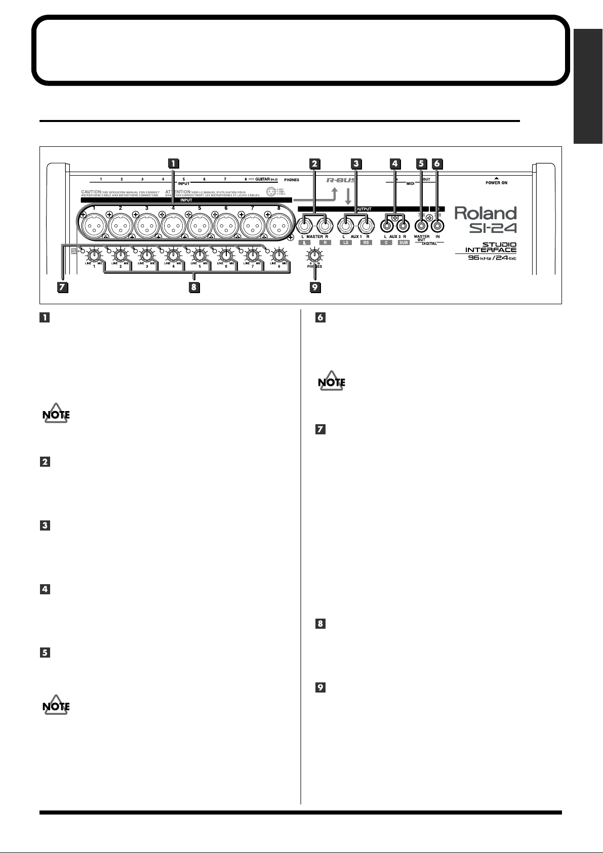
Input/output section
fig.**
INPUT jacks 1–8/XLR type
Devices with XLR type plugs can be connected to these jacks.
The audio that is input to INPUT 1–8 of the SI-24 will be sent
to “R-Bus In 1–8” of the RPC-1.
Phantom power can be supplied to each jack.
➔ For details, refer to “Using phantom power” (p. 16).
DIGITAL IN connector
Digital audio devices such as electronic musical instruments,
DAT recorders, or the Roland VS series can be connected to
this coaxial type connector.
In order to use digital input, you must change settings on the SI-24
and RPC-1. For details, refer to “Using the digital input” (p. 18).
Do not connect a plug to both the XLR and phone jacks for an
identically numbered INPUT.
MASTER jacks
These are analog audio output jacks.
They will output “R-Bus Out 1” and “R-Bus Out 2” of the
RPC-1. Use the MASTER fader to adjust the volume.
AUX1 jacks
These are analog audio output jacks.
They will output “R-Bus Out 3” and “R-Bus Out 4” of the
RPC-1.
AUX2 jacks
These are analog audio output jacks.
They will output “R-Bus Out 5” and “R-Bus Out 6” of the
RPC-1.
DIGITAL OUT connector
This is a digital audio (stereo) output connector.
It outputs “R-Bus Out 1/2” of the RPC-1.
If desired, the RPC-1’s “R-Bus Out 7/8” can be output from
DIGITAL OUT. For details, refer to “Outputting the RPC-1’s R-Bus
Out 7/8 from the SI-24” (p. 30).
Peak indicators
● Input level
These indicate whether the sound being input to each INPUT
jack is distorting. They provide a guideline for adjusting the
input sensitivity knobs to an appropriate input level.
➔ For details, refer to “Adjusting the input sensitivity”
(p. 17).
● Phantom power
While you hold down [SHIFT], these indicate the phantom
power on/off status.
Indicator lit: phantom power on
Indicator dark: phantom power off
➔ For details, refer to “Using phantom power” (p. 16).
INPUT sensitivity knobs
These knobs adjust the input sensitivity of the INPUT jacks.
➔ For details, refer to “Adjusting the input sensitivity”
(p. 17).
PHONES knob
Adjusts the volume of the headphones.
9
Page 10
Panel Description
Control section
fig.**
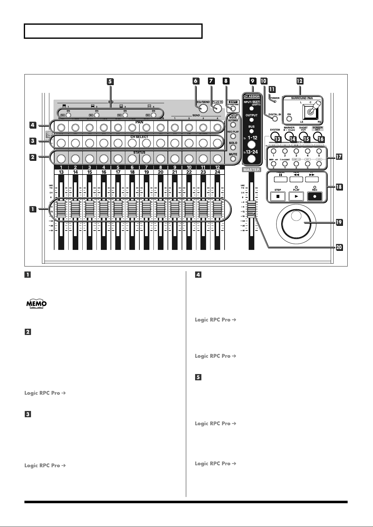
Faders
These move the on-screen faders to adjust the volume level of
the channels.
When you use the mouse to move the on-screen faders, the faders of
the SI-24 will move in tandem.
STATUS buttons
STATUS MODE
The function of [STATUS] will change according to the
selected STATUS MODE.
Pressing [STATUS] repeatedly changes the status of the
channel. The current status is shown by the color of the
button.
For details, refer to “Selecting channels”
(p. 32).
CH SELECT (Channel Select) buttons
Select the channel that will be the object of operations. The
[CH SELECT] indicator of the selected channel will light.
When used in conjunction with [SHIFT], these will function as
phantom power switches for the INPUT jacks (XLR type).
For details, refer to “Using phantom power”
(p. 16).
PAN 1–12 knobs
Adjust the pan of the channels you selected in CH ASSIGN
(channel assign).
When [EQ/SEND] is on (lit), these knobs control the equalizer
or bus send levels.
For details, refer to “Controlling the
equalizer” (p. 34) or “Controlling the bus send levels” (p. 35).
When [PLUG-IN] is on (lit), these knobs control plug-in
parameters.
For details, refer to “Controlling plug-ins”
(p. 35).
ON/INS (On/Insert) 1–4 buttons
● When [EQ/SEND] is on (lit)
Functions as EQ [ON].
Switches each of the four equalizer bands on/off. When the
equalizer is on, EQ [ON] will light.
For details, refer to “Controlling the
equalizer” (p. 34).
● When [PLUG-IN] is on (lit)
Functions as [INS]. Selects the plug-in that is to be edited.
For details, refer to “Controlling plug-ins”
(p. 35).
10
Page 11
Panel Description
Panel Description
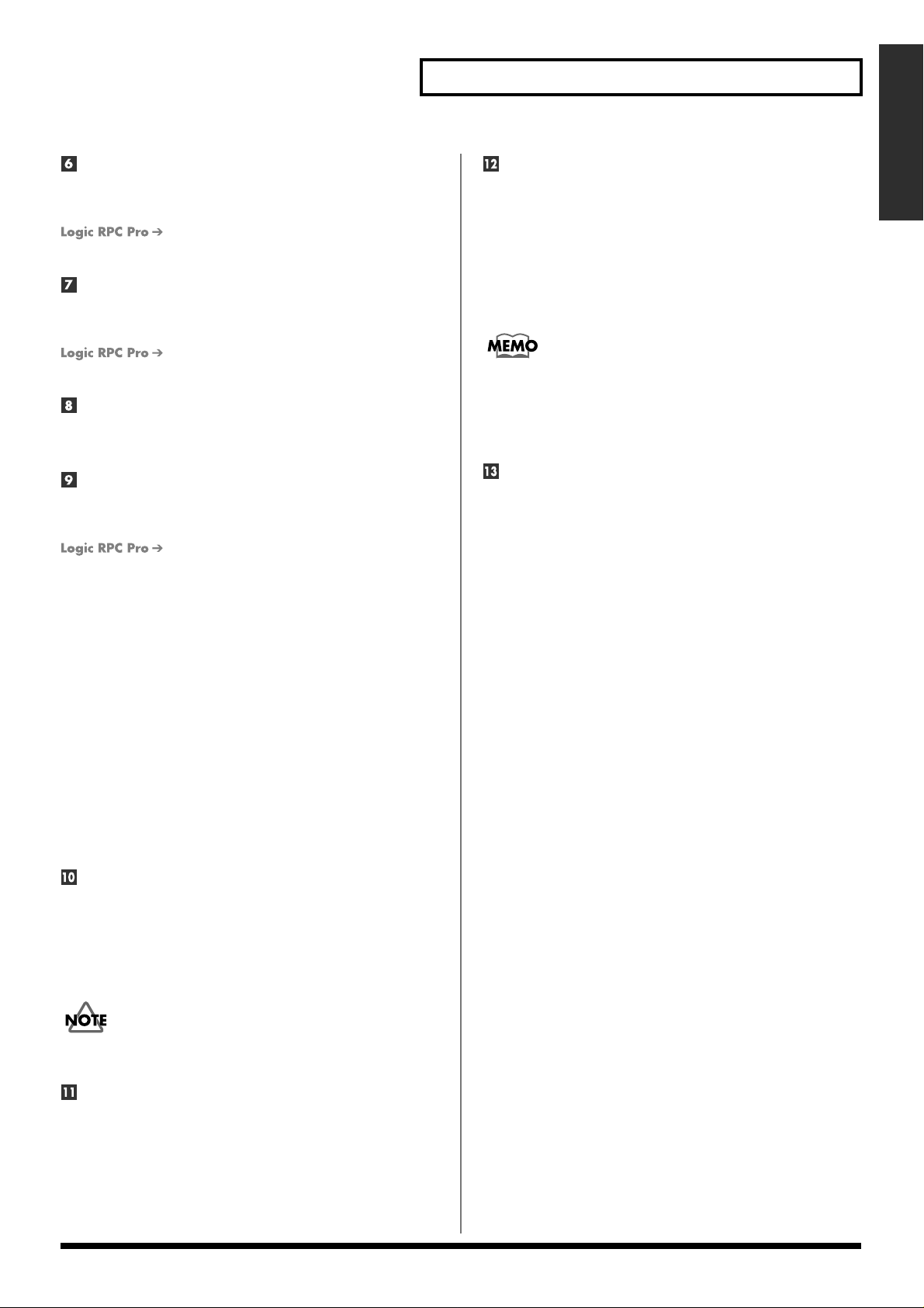
EQ/SEND (Equalizer/Send) button
When [EQ/SEND] is on (lit), you can use PAN knobs 1–12 to
adjust the equalizer or the bus send level.
For details, refer to “Controlling the
equalizer” (p. 34 or “Controlling the bus send levels” (p. 35).
PLUG-IN button
When [PLUG-IN] is on (lit), you can adjust various parameters
of the plug-in.
For details, refer to “Controlling plug-ins”
(p. 35).
SHIFT button
This is used in conjunction with other buttons to change the
function of those buttons.
CH ASSIGN (Channel Assign)
Use these buttons to select the mixer section that you want to
control. The selected button will light.
For details, refer to “Selecting channels”
(p. 32).
● INPUT/INST (Input/Instrument) button
Select this when you want to control the inputs.
When you want to control instruments, hold down the
[SHIFT] key and select [INPUT/INST].
● OUTPUT button
Select this when you want to control the outputs.
● BUS button
Select this when you want to control the buses.
● Tr 1–12 (Track 1–12) button
Select this when you want to control tracks 1–12.
● Tr 13–24 (Track 13–24) button
Select this when you want to control tracks 13–24.
DIGITAL IN button
Use this when you want to send the DIGITAL IN input to the
RPC-1.
When [DIGITAL IN] is on (lit), the input signal from DIGITAL
IN (instead of the analog signal from INPUT 7–8) will be sent
to the RPC-1.
In order to use digital input, you must also change settings on the
RPC-1. For details, refer to “Using the digital input” (p. 18).
POWER indicator
This indicates the power on/off status of the SI-24. The
indicator will light when the power is on.
SURROUND PAN
● ON button
This button switches Surround mode on/off.
When SURROUND PAN [ON] is on (lit), the currently selected
channel will switch to surround mode. At the same time, the
Surround screen will appear.
When surround mode is switched off, the normal pan display
will reappear.
The PAN knob will not function when Surround mode is on.
● Joystick
When SURROUND PAN [ON] is on (lit), this controls
surround panning.
SYSTEM button
This button is used to make SI-24 system settings. While you
hold down [SYSTEM], [0]–[9] will function as system setting
buttons.
[1]–[5]: Select the protocol.
➔ For details, refer to “Selecting the protocol” (p. 25).
[6] (MIDI Ctrl):
When this is on (lit), a computer or MIDI device connected
to the SI-24 can be controlled via the MIDI connector.
➔ For details, refer to “Using the MIDI connectors to
transmit/receive control data—MIDI Control Mode”
(p. 29).
[7] (7/8>D.OUT):
When this is on (lit), the RPC-1’s “R-Bus Out 7/8” signal
will be output from DIGITAL OUT.
➔ For details, refer to “Outputting the RPC-1’s R-Bus
Out 7/8 from the SI-24” (p. 30).
[8] (DUMP/LD):
Use this when you want to save user mode settings on
your computer, or to load previously saved data.
➔ For details, refer to “Saving user mode settings on your
computer—Dump” (p. 28), or “Loading user mode
settings that were saved on your computer—Load” (p. 28).
[9] (KEY):
When making user mode settings, this switches key/fader
setting mode on/off.
➔ For details, refer to “Setting/registering user mode
settings” (p. 26).
[0] (LED):
When making user mode settings, this switches LED
setting mode on/off.
➔ For details, refer to “Making/registering user mode
settings” (p. 26).
11
Page 12
Panel Description
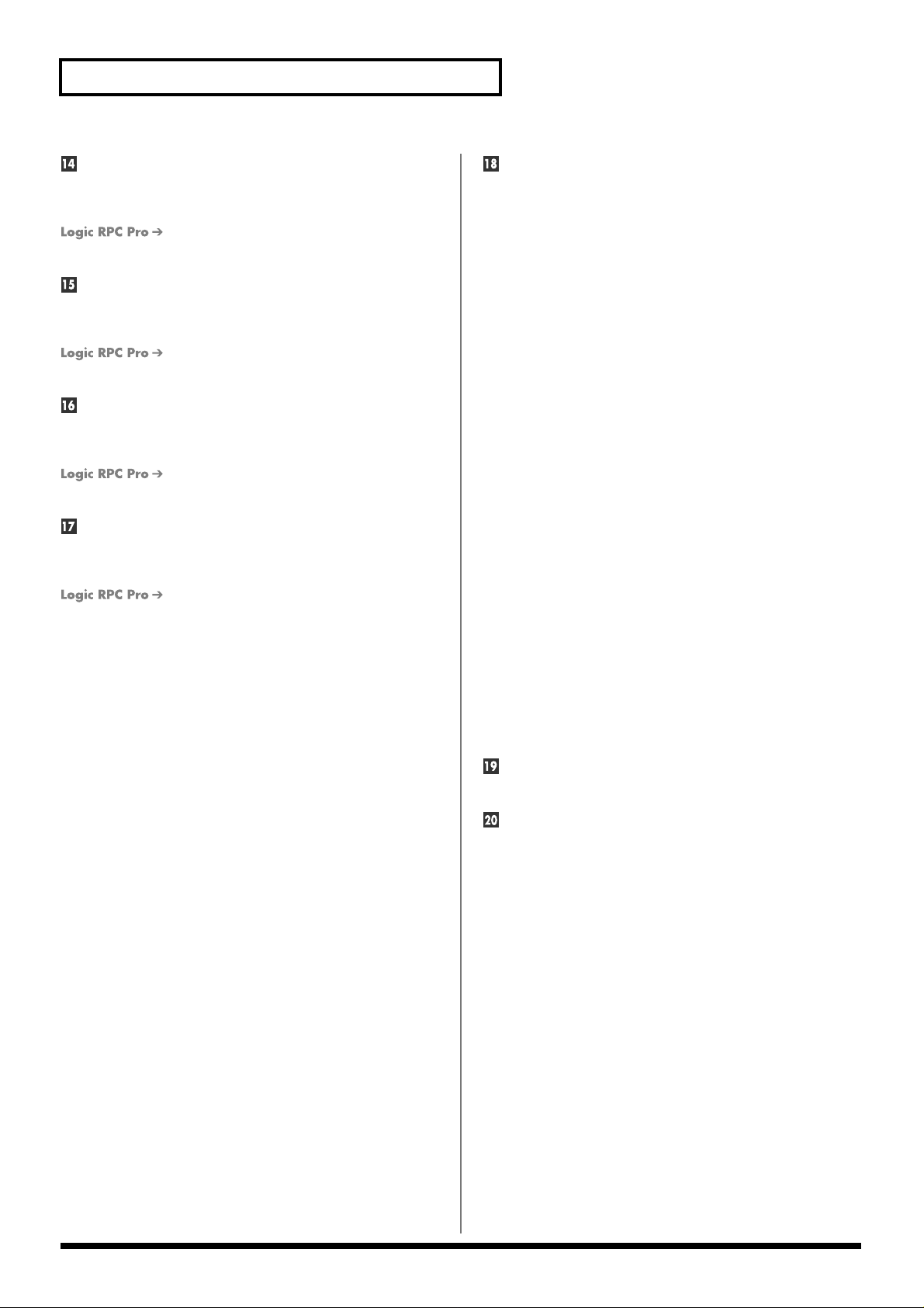
MARKER button
When [MARKER] is on (lit), [0] will function as the Marker
Request button. Markers will be registered (stored) to [1]–[9].
For details, refer to “Registering a song
location—Marker Create” (p. 36).
SHORTCUT button
When [SHORTCUT] is on (lit), [0]–[9] will function as
command execution buttons.
For details, refer to “SHORTCUT button
operations” (p. 37).
SCREEN SET button
When [SCREEN SET] is on (lit), [0]–[9] will function as
screen set buttons.
For details, refer to “Recalling screens
registered to the numeric keys—Screen Set” (p. 37).
[0] –[9]
These are used as marker buttons, screen set buttons, shortcut
buttons, and system setting buttons.
For details, refer to the corresponding
section.
To use as marker buttons:
“Registering song locations—Marker Create” (p. 36)
To use as screen set buttons:
“Recalling screens registered to the numeric keys—Screen
Set” (p. 37)
To use as shortcut buttons:
“SHORTCUT button operations” (p. 37)
To use as system setting buttons:
“Making system settings” (p. 25–30)
Transport
These buttons operate the transport.
● STOP button
Stops playback or recording.
● PLAY indicator
This will light during playback or recording.
● PLAY button
Starts playback.
● REC (Recording) indicator
This will light during recording.
● REC (Recording) button
Starts recording.
● PAUSE button
Pauses song playback or recording.
● REW (Rewind) button
Logic RPC Pro:
Rewind the song. Press [STOP] to stop rewinding.
Pro Tools/Cubase:
While you hold down [REW], the song will rewind.
● FF (Fast-forward) button
Logic RPC Pro:
Fast-forward the song. Press [STOP] to stop fastforwarding.
Pro Tools/Cubase:
While you hold down [FF], the song will fast-forward.
Jog dial
This moves the time location within the song.
MASTER fader
This adjusts the overall volume.
The MASTER fader always controls the RPC-1’s “R-Bus Out
1–2” fader, regardless of the CH ASSIGN (Channel Assign)
selection.
12
Page 13
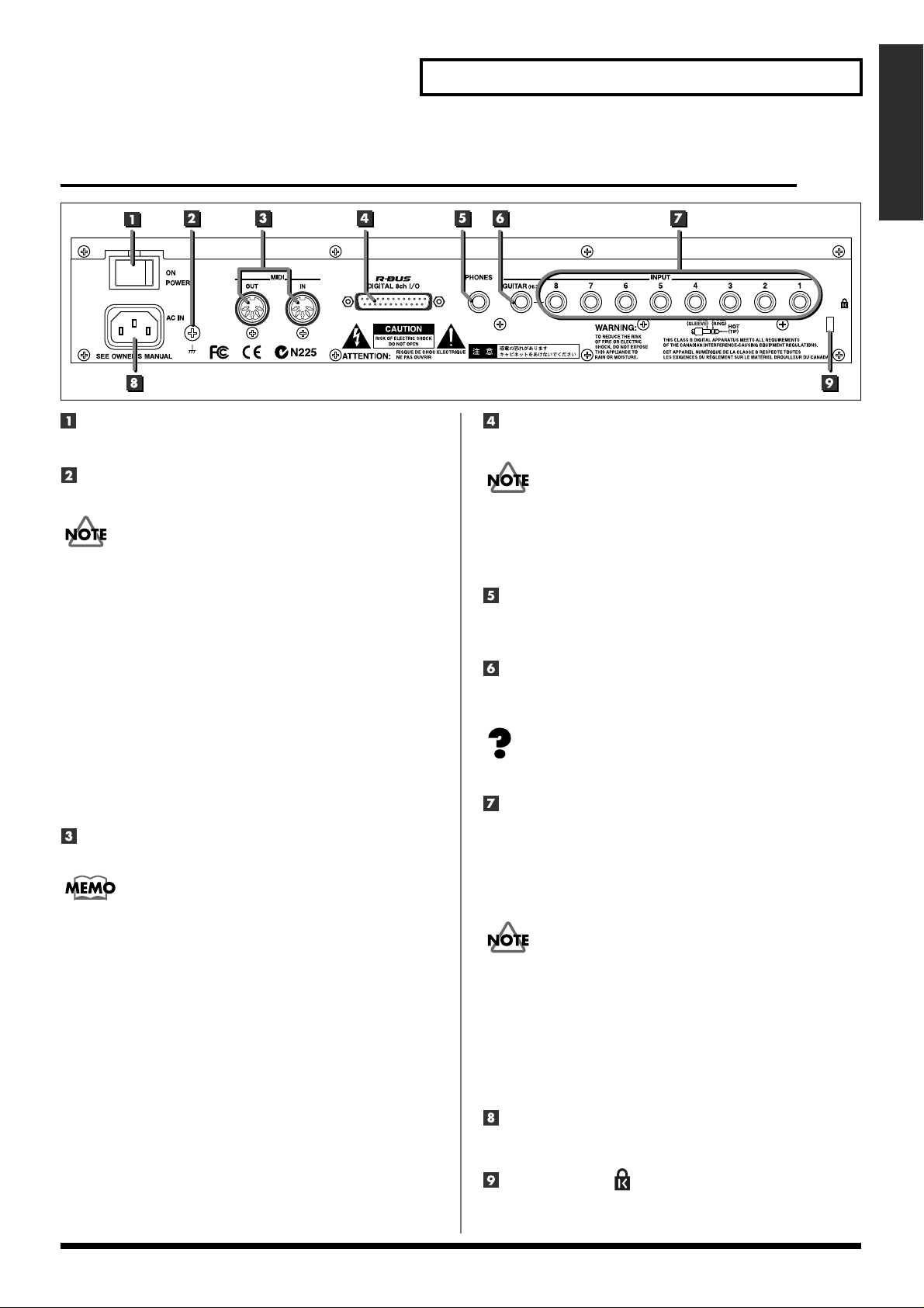
Rear panel
Panel Description
Panel Description
Panel Description
Power switch
Turns the power on/off.
Earth Connector
Connect the ground cable here.
In some cases, depending on the environment in which the unit is
installed, the surface of the panel may sometimes feel rough and
grainy. This is due to an infinitesimal electrical charge, which is
absolutely harmless. However, if you are concerned about this,
connect the ground terminal (see figure) with an external ground.
When the unit is grounded, a slight hum may occur, depending on
the particulars of your installation. If you are unsure of the
connection method, contact the nearest Roland Service Center, or an
authorized Roland distributor, as listed on the “Information” page.
Unsuitable places for connection
• Water pipes (may result in shock or electrocution)
• Gas pipes (may result in fire or explosion)
• Telephone-line ground or lightning rod (may be dangerous in the
event of lightning)
MIDI connectors (IN, OUT)
Connect a MIDI sequencer or other external MIDI device here.
In order for a MIDI device connected to the SI-24 to be controlled via
the MIDI connector, you must switch MIDI Control Mode on. For
details, refer to “Using the MIDI connectors to transmit/receive
control data—MIDI Control Mode” (p. 29).
● IN
This connector receives MIDI messages from another MIDI
device. Connect it to the MIDI OUT connector of the external
MIDI device.
● OUT
This connector transmits MIDI messages. Connect it to the
MIDI IN connector of the external MIDI device.
R-BUS connector
Use this connector to connect the SI-24 and RPC-1.
• You must use a special R-BUS cable to make this connection.
The SI-24 cannot use a five meter R-BUS cable (RBC-5).
• The R-BUS connector of SI-24 can not be used by connecting with
the equipment requires power supply via R-BUS such as DIF-AT,
VE-7000 and so on.
PHONES jack
A set of stereo headphones can be connected here.
* This jack will output the same sound as MASTER L/R.
GUITAR jack
This is a high-impedance jack. An electric guitar or bass can be
connected directly to this jack.
Impedance (p. 46)
INPUT jacks 1–8/phone type
These jacks allow devices with phone plugs to be connected.
The audio signals that are input to INPUT 1–8 of the SI-24 are
sent to “R-Bus In 1–8” of the RPC-1.
* These are TRS phone jacks that allow either balanced or unbalanced
connections.
• You cannot use the GUITAR jack and the INPUT 8 jack (phone
type/XLR type) simultaneously. If devices are connected to both
jacks, the GUITAR jack input will take priority. If you want to use
the input from the INPUT 8 jack (phone type/XLR type), do not
connect anything to the GUITAR jack.
• Do not connect plugs to both the XLR type and phone type
INPUT jack of the same number.
• When using the phone type INPUT jack, you must switch
phantom power off.
AC inlet
Connect the power supply cable to this inlet.
Security Slot ( )
You can lock this product using ordinary sold security wire
etc. See “http://www.kensington.com/” for details.
13
Page 14
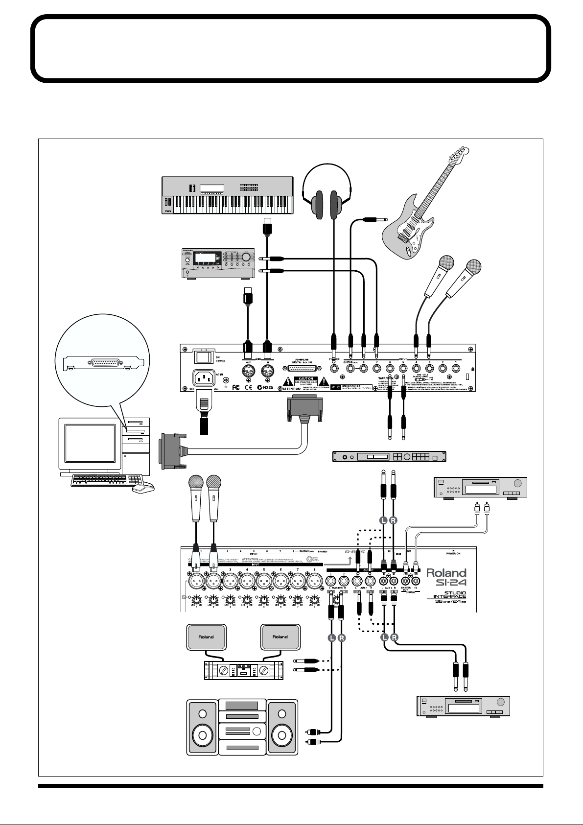
Preparing to use the SI-24
Connecting peripheral equipment
Make connections correctly, as shown in the diagram below.
fig.02-**
RPC-1
Keyboard etc.
MIDI Sound Module etc.
To Power Outlet
Stereo Headphones
Electric Guitar
Electric Bass
Mic
PC
Mic
Power amp
Effect etc.
DAT Recorder, VS series, etc.
DAT Recorder, VS series, etc.
14
Audio Set etc.
Page 15
Preparing to use the SI-24
• Do not connect plugs to both the XLR type and
phone type INPUT jack of the same number.
• You cannot use the GUITAR jack and the INPUT 8 jack
(phone type/XLR type) simultaneously. If devices are
connected to both jacks, the GUITAR jack input will take
priority. If you want to use the input from the INPUT 8
jack (phone type/XLR type), do not connect anything to
the GUITAR jack.
• If using the phone type INPUT jack, you must switch
phantom power off. For details, refer to “Using phantom
power” (p. 16).
• In order to handle audio with the SI-24 and to transfer
audio between the SI-24 and your computer, you must
connect it to a computer in which an R-BUS interface card
(RPC-1) has been installed.
You must use a special R-BUS cable to make this connection.
•
The SI-24 cannot use a five meter R-BUS cable (RBC-5).
•
The R-BUS connector of SI-24 can not be used by connecting with
the equipment requires power supply via R-BUS such as DIF-AT,
VE-7000 and so on.
• To prevent malfunction and/or damage to speakers or
other devices, always turn down the volume, and turn off
the power on all devices before making any connections.
Preparing to use the SI-24
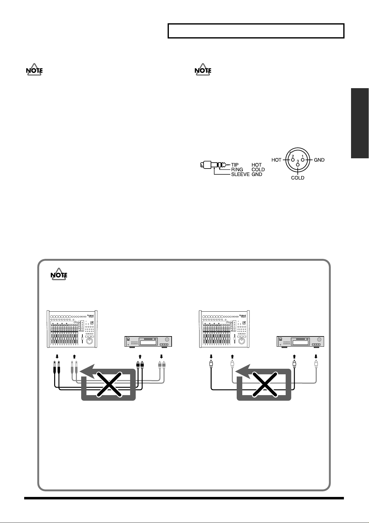
• This instrument is equipped with balanced (XLR/TRS)
type input jacks. Wiring diagrams for these jacks are
shown below. Make connections after first checking the
wiring diagrams of other equipment you intend to
connect.
• Howling could be produced depending on the location of
microphones relative to speakers. This can be remedied
by:
1. Changing the orientation of the
microphone(s).
2. Relocating microphone(s) at a greater
distance from speakers.
3. Lowering volume levels.
Be careful of loop connections
fig.3-2e
Example of an Analog Loop Connection Example of a Digital Loop Connection
SI-24
MD Recorder/
VS series etc.
OUTPUT INPUT
LINE OUTLINE IN DIGITAL OUT DIGITAL IN
When the SI-24 is connected as shown in the above diagram to a device that passes the input sound through
to its output (a DAT recorder/the Roland VS series that is recording), the SI-24 and that device will form a
loop that can cause oscillation, producing an unexpectedly loud sound.
This type of connection can cause malfunction and damage to speakers and other equipment; take care to
avoid these conditions.
In addition to the above figure, take a moment now to check your connections for the following conditions.
• Could there be a looped connection between the analog and digital realms?
• Has any looped connection resulted from insertion of a mixer or other piece of equipment between the
devices?
SI-24
MD Recorder/
VS series etc.
DIGITAL OUTDIGITAL IN
15
Page 16
Preparing to use the SI-24
Turning the power on/off
■ Turning the power on
1. Use the rear panel POWER switch to turn on the power of the SI-24.
When the power is turned on, the power indicator will light.
2. Turn on the power of your audio system.
3. Raise the volume of your audio system to an appropriate level.
■
Turning the power off
1. Turn off the power of your audio system.
2. Use the rear panel POWER switch to turn off the power of the SI-24.
When the power is turned off, the power indicator will go out.
Using phantom power
Turn phantom power on if you connect a condenser mic that requires phantom
power. When phantom power is turned on, phantom power will be supplied to the
XLR type INPUT jacks.
• Always turn the phantom power off when connecting any device other than
condenser microphones that require phantom power. You risk causing damage if
you mistakenly supply phantom power to dynamic microphones, audio playback
devices, or other devices that don’t require such power. Be sure to check the
specifications of any microphone you intend to use by referring to the manual that
came with it. (This instrument’s phantom power: 15 V DC, 10 mA Max)
• Once the connections have
been completed (p. 14), turn
on power to your various
devices in the order specified.
By turning on devices in the
wrong order, you risk causing
malfunction and/or damage
to speakers and other devices.
• This unit is equipped with a
protection circuit. A brief
interval (a few seconds) after
power up is required before
the unit will operate normally.
• The SI-24 is able to supply phantom power to condenser mics for which the 15V
current is no more than 10 mA. Also, if you are using phantom power with multiple
INPUT jacks, you must ensure that the total current does not exceed 80mA. We
cannot guarantee operation for condenser mics that require more electrical power
than this. In such cases, you will need to use a phantom power supply device.
• Phantom power is not supplied to the phone type INPUT jacks on the rear panel. If
you need phantom power, use the XLR type INPUT jacks on the top panel.
• To prevent hazard or damage, ensure hat only microphone cables and microphones
designed to IEC-268-15A are connected.
• Afin d'eviter tout resque ou dommage, ne brancher que des cables de microphone
et des microphones conformes a la norme IEC-268-15A.
1. Hold down [SHIFT], and press the [CH SELECT] button of the number
corresponding to the INPUT jack for which you want to switch phantom power on.
❍ Number of [CH SELECT] buttons (1-8) corresponds to same numbered input
jacks (XLR).
❍ While you hold down [SHIFT], the peak indicators and [CH SELECT] will
show the phantom power on/off status.
16
Indicator lit: phantom power on
Indicator dark: phantom power off
Page 17

Adjusting the input sensitivity
Use the INPUT sensitivity knobs to adjust the input sensitivity. You can adjust the
input sensitivity over a range from line level (+4 dB) to mic level (-50 dB).
The peak indicators will light at a level below the point at which the sound distorts.
When you input sound, adjust the INPUT sensitivity knobs until your levels are as
high as you can get them without causing any peak indicators to light.
■
When connecting a mic
Preparing to use the SI-24
Preparing to use the SI-24
Set the INPUT sensitivity knob to about the 3 o’clock position.
■
When connecting an electronic musical instrument (synthesizer)
Set the INPUT sensitivity knob to about the 9 o’clock position.
■
When connecting an electric guitar or electric bass
Use the GUITAR jack if you want to connect an electric guitar or electric bass directly
to the SI-24. The input sensitivity of the GUITAR jack is adjusted with the INPUT 8
sensitivity knob. In this case, set the INPUT 8 sensitivity knob to about the 9
o’clock position.
Q: The volume level of the
instrument connected to
INPUT jacks are too low.
A: Could you be using a
connection cable that
contains a resistor?
Use a connection cable
that does not contain a
resistor.
17
Page 18

Preparing to use the SI-24
Using the digital input
The output of a digital audio device (e.g., electronic musical instrument, DAT
recorder, or the Roland VS series) connected to the SI-24 can be input to RPC-1 while
still in digital form.
If you want to use the DIGITAL IN input, use the following procedure to change the
settings.
1. Connect the SI-24’s DIGITAL IN connector to the digital out connector of your
digital audio device.
2. Press [DIGITAL IN] to turn it on (lit).
* In case [DIGITAL IN] blinks after pressing, no digital signal is coming to DIGITAL IN jack. (The
blinking of [DIGITAL IN] stops after a while and turns off.) Please check the connection or signal
from digital audio devices in such case.
3. Change the RPC-1 settings.
3-1. Access the RPC-1 Control Panel.
For details on operation, refer to the column “How to open the RPC-1 control
panel” (p. 20).
3-2. Select the “Hardware Settings” tab.
fig.digital-**
3-3. Change the “Master Clock” setting from
“Int. Clock” (Internal Clock) to “Ext. Clock”
(External Clock).
fig.digital-**
3-4. Change the “Ext. Clock Sample Rate”
setting the same frequency as the output of
the digital audio device.
The SI-24’s digital interface
complies with IEC60958
(consumer format). If you
want to use the digital input,
use a digital audio device that
IEC (p. 46)
How word clock is handled
on the SI-24
When [DIGITAL IN] is off
(dark), the SI-24 will
synchronize to the word clock
of the RPC-1. However, when
[DIGITAL IN] is on (lit), the
SI-24 will synchronize to the
word clock of the digital audio
device. In this case, the RPC-1
will also need to synchronize
to the word clock of the digital
audio device. In order for this
to happen, you must change
the settings of the RPC-1
(step 3).
3-5. Click to close the RPC-1 Control Panel.
When you have finished making RPC-1 settings, the input from DIGITAL IN
will be sent to the RPC-1, instead of the analog input from INPUT 7–8.
4. If you want to use the input from INPUT 7–8, turn [DIGITAL IN] off (dark). Then
change the RPC-1’s “Master Clock” setting to “Int. Clock.”
18
Page 19

Overall signal flow
OUTPUT
OUTPUT
RECORDER
RECORDER
OUTPUT 2
OUTPUT 1
TR 2
TR 1
OUTPUT 8
OUTPUT 7
TR 24
TR 23
Overall signal flow
INPUT OUTPUT
RPC-1
SI-24
INPUT 2
INPUT 1
INPUT MIXER
INPUT MIXER
Logic RPC Pro
19
Page 20

Monitoring the SI-24’s inputs
The SI-24 does not provide mixing functionality. For this reason, if you want to use
the master output or headphones to monitor the sounds that are being sent to the
SI-24’s inputs, the sounds that are being input to the SI-24 must be sent back from the
computer to the SI-24. Broadly speaking, there are three ways to return the input
sounds from the computer.
Using the RPC-1’s internal mixer to return the input sound (p. 21)
This allows latency-free monitoring (i.e., monitoring with no delay). Also, you will
be able to monitor the input sound at any time, unless you change the settings.
Using the RPC-1’s direct monitoring function to return the input sound (p. 23)
This allows latency-free monitoring only for the input sounds in your application
software.
Returning the input sound from your application software (p. 24)
This allows monitoring only for the input sounds that are set to record mode in your
application software. The sound will be delayed by the latency specified in the
RPC-1 control panel, but you will be able to monitor the sound processed by the
software effects.
How to open the RPC-1 control panel
If the computer is not
powered-on, you will not be
able to monitor the input
sound.
This is possible only when
using ASIO or EASI drivers on
Windows.
20
Windows 98/Me/2000:
Start ➔ Settings ➔ in the Control Panel, double-click “Roland RPC-1 H/W”
Windows XP:
Start ➔ double-click “Roland RPC-1 H/W” in the control panel (if this is not
displayed, click “Switch to classic view”)
Macintosh:
double-click the “Roland RPC-1 Control Panel” icon that you copied when
installing the software
Page 21

Monitoring the SI-24’s inputs
Using the RPC-1’s mixer to return the input sound
This allows latency-free monitoring (i.e., monitoring with no delay). Also, you will
be able to monitor the input sound at any time, unless you change the settings.
1. Open the RPC-1 control panel.
2. Click the “Monitor Mixer” tab.
3. Make settings as shown in the illustration.
fig.M01
Set both “WavOut 1/2” faders to 0 dB (highest).
Set pan to left and right.
Uncheck both “Mute” boxes.
For details on operation, refer
to the column “How to open
the RPC-1 control panel”
(p. 20).
4. Use the slide bar ( ) to scroll the screen to the left, to display
“R-Bus In 1/2”–”R-Bus In 7/8.”
5. Make settings as shown in the illustration.
fig.M02
Set all of the “R-Bus In 1/2”–“R-Bus In 7/8”
faders to 0 dB (highest).
Adjust the pan as appropriate.
Uncheck all “Mute” boxes.
fig.M03
6. Click the “Patchbay/Router” tab.
fig.M04
7. As shown in the illustration, set the “R-Bus Out 1/2”
source to “Monitor Mixer.”
Monitoring the SI-24’s inputs
21
Page 22

Monitoring the SI-24’s inputs
8. Click the “Hardware Settings” tab.
9. ● Windows 98/ME
Check “Disable audio app use of Monitor Mixer and Patchbay/Router.”
fig.M05
● Windows 2000/XP
Check “Disable Control of the Monitor Mixer and Patchbay/Router by Audio
Applications.”
fig.M05
10.Click , assign a name to your settings, and click to save
them.
fig.M06
In the event that the settings
are changed, click the RPC-1
control panel ,
and load the settings you
saved in step 10.
11.Click to close the RPC-1 control panel.
12.Make the following settings according to the application you are using.
For details, refer to the manual for your application.
● Logic RPC Pro/Logic 5 users:
Audio ➔ Audio Hardware & Drivers
Uncheck “Software Monitoring” if you are using ASIO or EASI drivers.
fig.M09
● Cubase users:
Options ➔ Audio Setup ➔ System
Check “ASIO Direct Monitoring” and “Global Disable.”
fig.M08
22
Page 23

Monitoring the SI-24’s inputs
Using the RPC-1’s direct monitoring function to return the input sound
This allows latency-free monitoring only for the input sounds in your application
software.
1. Open the RPC-1 control panel.
2. Click the “Hardware Settings” tab.
3. ● Windows 98/ME
Uncheck “Disable audio app use of Monitor Mixer and Patchbay/Router.”
fig.M05
● Windows 2000/XP
Uncheck “Disable Control of the Monitor Mixer and Patchbay/Router by Audio
Applications.”
fig.M07
4. Make the following settings according to the application you are using.
For details, refer to the manual for your application.
● Logic RPC Pro/Logic 5 users:
Audio ➔ Audio Hardware & Drivers
Uncheck “Software Monitoring” if you are using ASIO or EASI drivers.
fig.M09
This is possible only when
using ASIO or EASI drivers on
Windows.
For details on operation, refer
to the column “How to open
the RPC-1 control panel”
(p. 20).
Monitoring the SI-24’s inputs
● Cubase users:
Options ➔ Audio Setup ➔ System
Check “ASIO Direct Monitor” and “Record Enable Type.”
fig.M08
23
Page 24

Monitoring the SI-24’s inputs
Returning the input sound from your application software
This allows monitoring only for the input sounds that are set to record mode in your
application software. The sound will be delayed by the latency specified in the
RPC-1 control panel, but you will be able to monitor the sound processed by the
software effects.
1. Open the RPC-1 control panel.
2. Click the “Hardware Settings” tab.
3. ● Windows 98/ME
Check “Disable audio app use of Monitor Mixer and Patchbay/Router.”
fig.M05
● Windows 2000/XP
Check “Disable Control of the Monitor Mixer and Patchbay/Router by Audio
Applications.”
fig.M10.
For details on operation, refer
to the column “How to open
the RPC-1 control panel”
(p. 20).
4. Make the following settings according to the application you are using.
For details, refer to the manual for your application.
● Logic RPC Pro/Logic 5 users:
Audio ➔ Audio Hardware&Drivers
Check “Software Monitoring” if you are using ASIO or EASI drivers.
fig.M12
● Cubase users:
Options ➔ Audio Setup ➔ System
• Uncheck “ASIO Direct Monitoring.”
• Check “Record Enable Type.”
fig.M11
24
Page 25

Making system settings
b
b
Making settings appropriate for your application
Selecting the protocol
In order to use the SI-24 to control your application, you must select the appropriate
protocol.
1. Hold down [SYSTEM] and press the mode button [1]–[5] for the settings you
want to use.
The button you pressed will light, and the settings will be switched.
The modes are assigned to [1] –[5] as follows.
[1] (L5): Logic 5 mode. These settings are for Logic RPC Pro/Logic 5.
For details, refer to “Controlling Logic RPC Pro” (p. 31).
[2] (H): Pro Tools mode. These settings are for Pro Tools.
For details, refer to “Controlling Pro Tools (version 4.1 or later)” (p. 38).
[3] (S.C): Cubase mode. These settings are for Cubase.
For details, refer to “Controlling Cubase VST (version 5.0 or later)”
(p. 42).
[4] (USR 1): User mode 1. These are user settings you registered (stored) in
“Setting/registering user mode settings” (p. 26).
If you select a mode that is not
appropriate for your
application, the SI-24 will not
e able to control the
application correctly.
While you hold down
[SYSTEM], one of the mode
uttons will light to indicate
the current mode.
[5] (USR 2): User mode 2. These are user settings you registered (stored) in
“Setting/registering user mode settings” (p. 26).
Making system settings
25
Page 26

Making system settings
Setting/registering user mode settings
You can assign different MIDI events of your choice to the buttons and knobs of the
SI-24, and register these settings to [4] (USR 1) or [5] (USR 2). The settings you
register will be remembered even when the power is turned off.
■
Assigning MIDI events to buttons and faders (Send)
As an example, here’s how to make user mode settings for [4] (USR 1).
1. Hold down [SYSTEM] and press [4] (USR 1) to select the location for which you
want to register settings.
[SYSTEM] and [4] (USR 1) will light, and user mode 1 will be selected.
2. Press [9] (KEY).
[9] (KEY) are turned on (lit), and you will enter key/fader setting mode.
3. Operate the key (button, PAN knob, fader, or the jog dial) for which you want to
assign a MIDI event.
The key you moved last will be the key your MIDI parameter will be assigned to.
4. Input the MIDI event that you want to send when keys or faders are operated
from R-BUS or from MIDI IN.
[4] (USR 1) will change from lit to blinking, indicating that the setting has been
changed.
* Whether you input the MIDI event from R-BUS or from MIDI IN will depend on the MIDI
control mode setting. For details, refer to “Using the MIDI connectors to transmit/receive control
data—MIDI Control Mode” (p. 29).
5. Input the MIDI event that you want to send when you leave your fingers from
buttons via R-BUS or MIDI IN.
* In case you do not want to send MIDI event when you leave your fingers from buttons, this step
is not necessary.
6. Press [9](KEY) again.
[9] (KEY) turns off and returns to user mode 1. Press the key specified on above step
3 to check the assignment.
If you want to correct, return to above step 2.
7. Repeat steps 2–6 as necessary to make assignments for other keys.
8. To finalize the user settings, press [4] (USR 1).
[4] (USR 1) will change from blinking to lit, indicating that the settings have been
finalized. At the same time, [9] (KEY) will turn off (go dark).
If you press [MARKER], [SHORTCUT], or [SCREEN SET] instead of [4] (USR 1),
the settings will not be registered. [9] (KEY) will turn off (go dark), and you will
return to the state the SI-24 was in before you made the settings.
User mode settings can also be
saved on your computer or
another device. For details,
refer to “Saving user mode
settings on your computer—
Dump” (p. 28). To load the
user mode settings you saved,
refer to “Loading user mode
settings from your computer—
Load” (p. 28).
SI-24 supports the MIDI
message as follows.
<Buttons>
• Note On/Off
• Polyphonic Key Pressure
• Pitch Bend
• Control Change
• Channel Pressure
• Program Change
<Faders>
• Note On/Off
• Polyphonic Key Pressure
• Pitch Bend
• Control Change
Specify fader parameter by
number of third byte.
➔ 0 (bottom)–127 (top)
<PAN knobs/Jog dial>
• Note On/Off
• Polyphonic Key Pressure
• Pitch Bend
• Control Change
The following number will be
inserted at third byte.
Rotated counter clock wise: 127
Rotated clock wise: 1
26
Page 27

■ Assigning MIDI events to LEDs and faders (Return)
As an example, here’s how to make user mode settings for [4] (USR 1).
1. Hold down [SYSTEM] and press [4] (USR 1) to select the button for which you
want to register settings.
[SYSTEM] and [4] (USR 1) will light, and user mode 1 will be selected.
2. Press [0] (LED).
[0] (LED) will turn on (lit), and you will enter the LED setting mode.
3. Operate the button to which you want to assign a MIDI event.
If you operate more than one button, the button/fader you operated last will be the
button your MIDI parameter will be assigned to.
4. Input the desired MIDI event from R-BUS or from MIDI IN.
[4] (USR 1) will change from lit to blinking, indicating that the setting has been
changed.
* You cannot assign single MIDI event to multiple faders or buttons. In case fader moves or button
blinks on input of MIDI event, it means the MIDI event is already assigned.
If you want to cancel the LED setting mode, press [0] (LED). The LED of [0] (LED) turns off.
Then return to step 1.
If you want to cancel the prior assignment and want to assign MIDI event on step 3, you need to
input MIDI event once again.
If you want the prior assignment unchanged, input different MIDI event.
* Whether you input the MIDI event from R-BUS or from MIDI IN will depend on the MIDI
control mode setting. For details, refer to “Using the MIDI connectors to transmit/receive control
data—MIDI Control Mode” (p. 29).
5. Press [0](LED) again.
[0] (LED) turns off and returns to user mode 1. Press button or move fader specified
on above step 3 to check the assignment.
If you want to correct, return to above step 2.
6. Repeat steps 3–5 as necessary to make assignments for other buttons/faders.
7. To finalize the user settings, press [4] (USR 1).
[4] (USR 1) will change from blinking to lit, indicating that the settings have been
finalized. At the same time, [0] (LED) will turn off (go dark).
If you press [MARKER], [SHORTCUT], or [SCREEN SET] instead of [4] (USR 1),
the settings will not be registered. [0] (LED) will turn off (go dark), and you will
return to the state you were in before you made the setting.
Making system settings
SI-24 supports the MIDI
message as follows.
<buttons/Faders>
Note On/Off
• Polyphonic Key Pressure
• Pitch Bend
• Control Change
Specify fader parameter or
color of LEDs by number of
third byte.
Faders
0 (bottom)–127 (top)
LEDs 0: Off
1: Lit Green
2: Lit red
3: Lit orange
others: Lit red
Making system settings
27
Page 28

Making system settings
Saving user mode settings on your computer—Dump
You can save user mode settings on your computer or sequencer. This provides a
convenient way to back up the settings you register to [4] (USR 1) or [5] (USR 2), or
allows you to prepare several sets of user mode settings.
As an example, here’s how to save [4] (USR 1) settings.
1. Hold down [SYSTEM] and press [4] (USR 1).
[SYSTEM] and [4] (USR 1) will light, and user mode 1 will be selected.
2. Press [8] (DUMP/LD).
[8] (DUMP/LD) will light, and the SI-24 will be ready to transmit data.
3. Operate your computer or external device so that it is ready to receive data.
4. Press [8] (DUMP/LD) once again.
[8] (DUMP/LD) will blink and the PLAY indicator will light, while the SI-24 is
transmitting MIDI messages.
When transmission is completed, [8] (DUMP/LD) and PLAY indicator will go dark.
Whether the SI-24 transmits the
MIDI message from R-BUS or
from MIDI OUT will depend on
the MIDI control mode setting.
For details, refer to “Using the
MIDI connectors to transmit/
receive control data—MIDI
Control Mode” (p. 29).
Loading user mode settings that you saved on your computer—Load
Here’s how user mode settings you saved on your computer or sequencer can be
loaded back into the SI-24.
As an example, we will describe the procedure for loading the saved settings into
[4] (USR 1).
1. Hold down [SYSTEM], and press [4] (USR 1).
[SYSTEM] and [4] (USR 1) will light, and you will switch to User Mode 1.
2. Press [8] (DUMP/LD).
[8] (DUMP/LD) will light, and the SI-24 will be ready to receive data.
3. Operate your computer or other external device to make it transmit previouslysaved User mode MIDI messages.
The PLAY indicator and REC indicator will light while the SI-24 is receiving the
MIDI message.
When reception is completed, [8] (DUMP/LD), the PLAY indicator, and REC
indicator will go dark.
Whether the SI-24 receives the
MIDI message from R-BUS or
from MIDI IN will depend on
the MIDI control mode setting.
For details, refer to “Using the
MIDI connectors to transmit/
receive control data—MIDI
Control Mode” (p. 29).
28
Page 29

Using the MIDI connectors to transmit/receive control data—MIDI Control Mode
With the factory settings, the SI-24 will transmit and receive control data via R-BUS.
If you are controlling a MIDI device or a computer that does not have R-BUS, set the
SI-24 to MIDI Control Mode so it will use the MIDI connectors to transmit and
receive control data.
1. Hold down [SYSTEM] and press [6] (MIDI Ctrl) to turn it on (lit).
If [6] (MIDI Ctrl) is on (lit):
MIDI Control Mode is selected. SI-24 control data will be transmitted from
MIDI OUT. If a device is connected to MIDI IN, control data from the
connected device will be received at MIDI IN.
If [6] (MIDI Ctrl) is off (dark):
SI-24 control data and control data from the connected device will be
transmitted and received via R-BUS.
2. To change the setting back, hold down [SYSTEM] once again and press
[6] (MIDI Ctrl).
[6] (MIDI Ctrl) will turn off (go dark).
Making system settings
The signal flow is as follows.
fig.04-**
● [6] (MIDI Ctrl): ON
● [6] (MIDI Ctrl): OFF
MIDI OUT
MIDI IN
MIDI OUT
MIDI OUT (channel 2–16)
MIDI IN
Making system settings
MIDI IN
(channel 2–16)
MIDI OUT
MIDI IN
29
Page 30

Making system settings
Outputting the RPC-1’s R-Bus Out 7/8 from the SI-24
With the factory settings, the RPC-1’s “R-Bus Out 7/8” will not be output from the
SI-24. If you want “R-Bus Out 7/8” to be output from the SI-24, change the setting as
follows.
1. Hold down [SYSTEM] and press [7] (7/8>D.OUT) to turn it on (lit).
If [7] (7/8>D.OUT) is on (lit):
RPC-1 “R-Bus Out 7/8” will be output from DIGITAL OUT.
If [7] (7/8>D.OUT) is off (dark):
RPC-1 “R-Bus Out 1/2” will be output from DIGITAL OUT.
2. To change the setting back, once again hold down [SYSTEM] and press
[7] (7/8>D.OUT).
[7] (7/8>D.OUT) will turn off (go dark).
The RPC-1’s “R-Bus Out 1–8” correspond to the SI-24’s OUTPUT as follows.
RPC-1
[7] (7/8>D.OUT): off (dark) [7] (7/8>D.OUT): on (lit)
R-Bus Out 1 MASTER-L, DIGITAL OUT (L) MASTER-L
R-Bus Out 2 MASTER-R, DIGITAL OUT (R) MASTER-R
R-Bus Out 3 AUX1-L AUX1-L
R-Bus Out 4 AUX1-R AUX1-R
R-Bus Out 5 AUX2-L AUX2-L
R-Bus Out 6 AUX2-R AUX2-R
R-Bus Out 7 – DIGITAL OUT (L)
R-Bus Out 8 – DIGITAL OUT (R)
SI-24 OUTPUT
30
Page 31

Controlling Logic RPC Pro
You can remotely control Logic RPC Pro from the SI-24.
* The software upgrade of Logic RPC Pro may make the operation process different or may include
additional functions.
Making the SI-24 settings
Use the following procedure to switch the settings of the SI-24.
1. Hold down [SYSTEM] and press [1] (L5).
[1] (L5) will light, and you will switch to Logic 5 mode.
2. If you want to use the MIDI connectors (and not R-BUS) to exchange data
between the SI-24 and your computer, hold down [SYSTEM] and press
[6] (MIDI ctrl) to turn it on (lit).
For details, refer to “Using the MIDI connectors to transmit/receive data—MIDI
Control Mode” (p. 29).
For details on modes
(protocols), refer to “Selecting
the protocol” (p. 25).
Making Logic RPC Pro settings
The setting of Logic RPC Pro should be made one following procedure.
1. Select [Scan] (Options ➔ Control Surfaces ➔ Scan).
1-1. Scan of the connected devices will start.
1-2. When your computer detect SI-24, the icon of SI-24 will appear on Setup
window.
You are now able to use SI-24 as remote controlling device for Logic PRC PRO.
Controlling Logic RPC Pro
31
Page 32

Controlling Logic RPC Pro
Selecting channels
1. Use CH ASSIGN to select the Logic RPC Pro mixer section that you want to
control.
The selected button will light.
[INPUT/INST]: Select this when you want to control INPUT.
If you want to control instruments, hold down [SHIFT] and press
[INPUT/INST].
[OUTPUT]: Select this when you want to control OUTPUT.
[BUS]: Select this when you want to control the buses.
[Tr 1–12]: Select this when you want to control TRACK 1–12.
[Tr 13–24]: Select this when you want to control TRACK 13–24.
For details on the Logic RPC
Pro mixer, refer to the column
“The structure of the Logic
RPC Pro mixer section”
(p. 32)
2. Press [CH SELECT] to select the channel that you want to control.
[CH SELECT] of the selected channel will light.
The structure of the Logic RPC Pro mixer section
The Logic RPC Pro mixer consists of the following five sections.
For each section you can change insert effect, bus send, pan, and volume settings.
Input section
■
This sends the inputs to the output section.
Instrument section
■
Software synthesizers are inserted here for use.
Output section
■
This mixes the sound of each channel and sends this mix to an output.
It is not possible to send audio
from the input section to the
track section. For details, refer to
“Overall signal flow” (p. 19).
You will need to purchase
software synthesizers separately.
32
Track section
■
These are the tracks that record the input audio on the hard disk of the computer
and play it back. The playback audio is sent to the buses or outputs.
Bus section
■
This section allows effects to be inserted and used as send effects, or can be used
as a group mixer.
Page 33

Switching the status of a channel
The function of [STATUS] will change depending on the STATUS MODE.
1. As described in the preceding section “Selecting channels,” select the Logic RPC
Pro mixer section that you want to control.
2. Select STATUS MODE, and press [STATUS] to switch the status of the channel.
The functions of STATUS MODE and [STATUS] correspond as follows.
STATUS MODE [STATUS] function
[MUTE] Switches muting on/off for each channel.
Lit: Mute on
Dark: Mute off
[SOLO] Switches solo on/off for each channel.
Lit: Solo on
Dark: Solo off
[REC/PLAY]
(Recording/Play)
[AUTOMIX] Switches the Automix Mode status of each channel.
Switches the record/playback status of each track.
Dark: The track can be played.
Lit red: Now recording.
Blinking red: Selected as a recording destination.
Record mode (lit red) will be selected when you press
[REC].
Lit green: Read automix (Read).
Lit red: Write automix (Write).
Lit orange: Automix will be overwritten from the moment
you operate the SI-24 (Latch).
Dark: Automix off (Off).
Controlling Logic RPC Pro
When you are writing automix data on Latch mode, it is
convenient to press [SHIFT] to
stop the movement of faders.
33
Controlling Logic RPC Pro
Page 34

Controlling Logic RPC Pro
Controlling the equalizer
The buttons and knobs of the SI-24 correspond to the Logic RPC Pro equalizer
parameters as follows.
fig.4-01
EQ4EQ1 EQ3EQ2
EQ1
EQ2
EQ3
EQ4
Logic RPC PRO
ON
(FREQ)
Hz
(GAIN)
dB
ON
(FREQ)
Hz
(GAIN)
dB
ON
(FREQ)
Hz
(GAIN)
dB
ON
(FREQ)
Hz
(GAIN)
dB
PAN knobs 1–8 will operate the equalizer (EQ GAIN 1–4, EQ FREQ 1–4).
Knob 1 ➔ EQ1 GAIN
Knob 2 ➔ EQ1 FREQ
Knob 3 ➔ EQ2 GAIN
Knob 4 ➔ EQ2 FREQ
Knob 5 ➔ EQ3 GAIN
Knob 6 ➔ EQ3 FREQ
Knob 7 ➔ EQ4 GAIN
Knob 8 ➔ EQ4 FREQ
Use the following procedure to operate the equalizer.
1. Press [EQ/SEND] to turn it on (lit).
2. As described in “Selecting channels” (p. 32), select the channel that you want to
control.
The [CHANNEL SELECT] of the selected channel will light.
3. Press EQ [ON] for the equalizer you want to operate, to turn it on/off.
When the equalizer is on, EQ [ON] will light.
4. Use knobs 1–8 to adjust the equalizer “GAIN” and “FREQ.”
In order to control equalizer
parameters from the SI-24, you
must first make settings EQ
Type in Logic RPC Pro.
For details on the procedure,
refer to the Logic RPC Pro
owner’s manual.
34
Page 35

Controlling the bus send levels
Controlling Logic RPC Pro
The send levels to four buses can be controlled from the SI-24.
PAN knobs 9–12 will control the send levels to the buses.
Knob 9 ➔ SEND 1
Knob 10 ➔ SEND 2
Knob 11 ➔ SEND 3
Knob 12 ➔ SEND 4
SEND 1
SEND 2
SEND 3
SEND 4
Use the following procedure to control the send levels.
1. Press [EQ/SEND] to turn it on (lit).
2. As described in “Selecting channels” (p. 32), select the channel that you want to
control.
The [CHANNEL SELECT] of the selected channel will light.
3. Use knobs 9–12 to adjust the send levels (SEND 1–4).
In order to control send levels
from the SI-24, you must first
make settings in Logic RPC
Pro to specify the buses to
which SEND 1–4 will be
assigned. For details on the
procedure, refer to the Logic
RPC Pro owner’s manual.
Controlling plug-ins
Logic RPC Pro lets you insert up to two plug-ins into each channel. An inserted plugin can be controlled from the SI-24.
EQ [ON 1] – [ON 2] will act as [INS 1] – [INS 2] to select the plug-in that you want
to edit.
[INS 1] (EQ [ON 1]) ➔ First plug-in
[INS 2] (EQ [ON 2]) ➔ Second plug-in
PAN knobs 1–11 will control the parameters of the plug-in.
Knobs 1–10 ➔ The parameters of the plug-in will automatically be
assigned to each knob.
Knob 11 ➔ Bypass function
1. As described in “Selecting channels” (p. 32), select the channel that you want to
control.
[CH SELECT] of the selected channel will light.
2. Press [PLUG-IN] to turn it on (lit).
3. Use [INS 1] – [INS 2] to select which plug-in you want to edit.
The PLUG-IN screen for the selected plug-in will appear.
4. Use knobs 1–11 to edit the parameters of the plug-in.
A maximum of ten plug-in
parameters can be controlled
from the SI-24.
Controlling Logic RPC Pro
If no plug-in has been inserted
into the channel you selected
in step 2, [PLUG-IN] will not
turn on (light).
35
Page 36

Controlling Logic RPC Pro
Registering a song location—Marker Create
Logic RPC Pro has a Marker Create function that lets you assign a marker at the
desired location in a song.
Here’s how to control Logic RPC Pro’s Marker Create function from the SI-24.
■
Assigning a marker
1. Press [MARKER] to turn it on (lit).
2. Move to the location that you want to register, and press the marker request
button [0].
You may do this while the song is recording, playing, or stopped.
Markers will be registered to [1]–[9] in playback order. Registered buttons will be lit.
About marker registration
The markers are registered to the nine buttons [1]–[9] in the order of playback. This
means that if you assign a new marker at a location that is earlier than a previously
assigned marker, subsequent markers will be renumbered upward.
fig.4-1
Marker1 Marker2
Marker1 Marker2
Moving to a marker location
■
1. Press [MARKER] to turn it on (lit).
2. Press a lit [1]–[9] button to move to the registered location.
Erasing a marker
■
1. Press [MARKER] to turn it on (lit).
2. Of the lit [1]–[9] buttons, press the button for the marker that you want to erase.
3. Hold down [SHIFT] and press [0].
The registration will be erased, and the button will go dark.
Marker3 Marker4 Marker5
Marker3 Marker4
Time
Time
36
Page 37

Recalling screens assigned to the numeric keys —Screen Sets
Logic RPC Pro lets you register various configurations of windows (“screen sets”) to
numeric keys 1–9 of the keyboard, and recall these screen sets by pressing a numeric
key.
Here’s how screen sets assigned to the numeric keys of the keyboard can be recalled
from the SI-24.
1. Press [SCREEN SET] to turn it on (lit).
2. Press one of the [1]–[9] buttons, and the screen set assigned to the corresponding
numeric key will be recalled just as if you had pressed a numeric key of the
keyboard.
SHORTCUT button Operations
Controlling Logic RPC Pro
You can lock/unlock the
screen set pressing [0]. When
screen set is locked, [0] lits.
[0]–[9] will execute the following Logic RPC Pro commands.
1. Press [SHORTCUT] to turn it on (lit).
[1]: Save [2]: Undo [3]: Copy [4]: Paste
[5]: Clear [6]: Scrub [7]: Cycle [8]: Drop
[9]: Automation View Volume [0]: Automation View Pan
Transport Operations
It is possible to control the transports of Logic RPC Pro using the following buttons.
[STOP]: Stops playback or recording.
[PLAY]: Starts playback.
[REC]: Starts recording.
[PAUSE]: Pauses song playback or recording.
[REW]: Rewind the song. Press [STOP] to stop rewinding.
[FF]: Fast-forward the song. Press [STOP] to stop fast-forwarding.
Jog dial: This moves the time location within the song.
Controlling Logic RPC Pro
37
Page 38

Controlling Pro Tools (version 4.1 or later)
Digidesign Pro Tools can be remotely controlled from the SI-24.
The SI-24 supports Pro Tools software version 4.1 or later.
Putting Pro Tools mode labels
■
When controlling Pro Tools, the button and knob functions will differ in some ways
from the panel. You will find it convenient to affix the included Pro Tools mode
labels when using the SI-24 with Pro Tools (see figure).
Before putting Pro Tools mode
labels on top panel of SI-24,
please wipe dust or dirt
adheres with a soft dry cloth.
Notes concerning the control of Pro Tools
● The SI-24 is not able to exchange audio with Pro Tools TDM or Pro Tools LE.
● When the protocol (p. 25) is Pro Tools mode, the following buttons and knobs
cannot be used.
• Faders 9–12
• Master fader
• [STATUS 9]
• [STATUS 10]
• CH ASSIGN [INPUT]
• Joystick
• SURROUND PAN [ON]
Making the SI-24 settings
Use the following procedure to switch the settings of the SI-24.
1. Hold down [SYSTEM] and press [2] (H).
[2] (H) will light, and Pro Tools mode will be selected.
For details on modes
(protocols), refer to “Selecting
the protocol” (p. 25).
2. If you want to use the MIDI connectors (and not R-BUS) to exchange data
between the SI-24 and your computer, hold down [SYSTEM] and press
[6] (MIDI ctrl) to turn it on (lit).
For details, refer to “Using the MIDI connectors to transmit/receive control data—
MIDI Control Mode” (p. 29).
38
Page 39

Making Pro Tools settings
*O
Use the following procedure to make settings in Pro Tools.
1. Start up Pro Tools.
2. From the Setups menu, choose Peripherals.
The Peripherals window will open.
fig.P1
2-1. Click .
Controlling Pro Tools (version 4.1 or later)
2-1
2-2
2-2. In MIDI Controllers #1, set Type to “HUI.” Also set the Receive from and Send
to fields to the device corresponding to the SI-24.
2-3. Click , and communication between Pro Tools and the SI-24
will begin.
3. From the Setups menu, choose “Preferences.”
The Preferences window will open.
fig.P2
3-1
3-2
3-1. Click .
3-2. For the Numeric Keypad Mode field, choose “Classic.” (*)
n software version 4.x of
Pro Tools, there is no setting
of “Numeric Keypad Mode.”
g.P
In some cases, the Macintosh will
frequently display an error message
stating that “Pro Tools can’t communicate
with HUI.”
In this case, exit Pro Tools, and then delete
“Pro Tools Preferences” from “Default
settings” in the “System folder.” Then
restart Pro Tools.
However, after restarting, the Peripherals
and Preference settings will have to be
made once again.
Controlling Pro Tools
39
Page 40

Controlling Pro Tools (version 4.1 or later)
b
How the SI-24’s controls will function
The explanation in this section will use the button names corresponding to the
included Pro Tools mode labels.
■
Faders 1–8
These control the faders of the area enclosed in blue within the Pro Tools Mix
window.
The target of control can be selected with [ ] (Tr 1-12), [ ] (Tr 13-24),
[] (OUTPUT), and [ ] (BUS).
■
STATUS buttons
These switch the status of the channel according to the selected STATUS MODE. The
current status is shown by the color of the buttons.
STATUS MODE [STATUS] function
[MUTE] Switches muting on/off for each channel.
Lit red: Mute on
Dark: Mute off
Blinking red: Muted by solo
[SOLO] Switches solo on/off for each channel.
Lit red: Solo on
Dark: Solo off
[REC/PLAY]
(Recording/Play)
[AUTOMIX] Switches the Automix Mode status of each channel.
■ CH SELECT (Channel Select) buttons
Switches the record/playback status of each track.
Lit green: The track can be played.
Lit red: Now recording.
Blinking red: Selected as a recording destination.
Record mode (lit red) will be selected when you press
[REC] or when you enter the auto-punch region.
Lit green: Read automix.
Lit red: Write automix.
Blinking red: Ready to write automix.
Dark: Automix off.
There are four automix writing
modes, as follows.
Write: Automix will be
overwritten.
Latch: Automix will be
overwritten from the
moment you operate
the SI-24.
Touch: Automix will be
overwritten only while
you are operating the
SI-24.
Trim:
Fader operations will
apply a relative change,
overwriting the data.
When you are writing automix data on Latch mode or
Touch mode, it is convenient
to press [SHIFT] to stop the
movement of faders.
These buttons select the target channel when you control the send levels or plug-ins.
The [CH SELECT] of the channel selected for operations will light.
By simultaneously pressing two or more [CH SELECT] buttons, you can create a
group of channels.
If all [CH SELECT] buttons are
dark, a track outside the range
eing controlled by the SI-24
has been selected.
For details, refer to “SHORTCUT button” (p. 41).
■
PAN 1–8 knobs
These control the channel panning.
You can control the panning more precisely by turning [SHORTCUT] on (lit) and
then holding down [8] (FINE) while you turn the knobs.
40
Page 41

■ EQ/SEND (Equalizer/Send) buttons
b
Controlling Pro Tools (version 4.1 or later)
You can press [EQ/SEND] to turn it on (lit), and use SEND 1–4 (PAN 9–12) to control
the send levels of the channel you selected in [CH SELECT].
■ PLUG-IN button
When you press [PLUG-IN] to turn it on (lit), you will be able to control plug-in
effects.
Use the following procedure to control plug-in effects.
1. Press [PLUG-IN] to turn it on (lit).
The plug-in window will appear.
2. Use [CH SELECT] to select the track into which the plug-in you want to control
has been inserted.
3. Use [INS 1] (ON 1)–[INS 4] (ON 4) to select the slot into which the plug-in you
want to control has been inserted.
4. Use PARAM 1–4 (PAN 9–12) and [ON 1–4] (CH SELECT 9–12) to control the
parameters of the plug-in.
5. Use [< SCROLL] (STATUS 11) or [SCROLL >] (STATUS 12) to change the range
of parameters being controlled. Knobs or buttons within the region of
parameters being controlled will be displayed in blue.
If you want to view the send
levels in the screen, choose the
Display menu in Pro Tools,
and in “Sends View Shows,”
select Send A–D as desired.
■
MARKER button
When you press [MARKER] to turn it on (lit), [0] will function as the marker request
button. Markers will be registered to [1]–[9], and you can press one of these buttons
to move to the registered location.
■
SHORTCUT button
When you press [SHORTCUT] to turn it on (lit), [0]–[9] will execute the following
Pro Tools commands.
[1]: Save [2]: Undo [3]: Copy [4]: Paste [5]: Clear
[6]: Group [7]: Create Group [8]: Fine [9]: Escape [0]: Enter
■
SCREEN SET button
When you press [SCREEN SET] to turn it on (lit), [1]–[6] will open the Pro Tools
window assigned to each button.
[1]: Mix [2]: Edit [3]: Transport
[4]: Memory Locations [5]: Status [6]: Plug-in
■
Transport
You can use [STOP], [PLAY], [REC], [ZERO RETURN] (PAUSE), [REW], and [FF]
to operate the Pro Tools transport.
You can use the jog dial to move the song position line.
[7] (Create Group) groups the
tracks that you selected by
simultaneously pressing two
or more [CH SELECT]
uttons. [6] (Group) turns the
group function on/off. While
you hold down [8] (Fine), you
will be able to adjust the pan or
send level more precisely.
Controlling Pro Tools
41
Page 42

Controlling Cubase VST (version 5.0 or later)
The SI-24 can remotely control Steinberg Corporation’s Cubase series programs.
•A remote control file is required for Cubase settings.
You can download a remote control file for Cubase from the Roland web site.
http://www.roland.co.jp/
• The SI-24 supports Cubase version 5.0 and later.
Cautions when controlling Cubase
● When the selected protocol (p. 25) is “Cubase mode,” the following buttons and
knobs cannot be used.
• STATUS MODE [REC/PLAY] and [AUTOMIX]
• Joystick
• SURROUND PAN [ON]
● When used with Cubase, the SI-24’s MIDI is used only for VST remote. In this
case, the SI-24 cannot be used as a MIDI interface.
Making the SI-24 settings
Use the following procedure to make settings on the SI-24.
1. Hold down [SYSTEM] and press [2] (S.C.).
[2] (S.C.) will light, and the SI-24 will switch to Cubase mode.
2. If you want to use the MIDI connectors (and not R-BUS) to exchange data
between the SI-24 and your computer, hold down [SYSTEM] and press
[6] (MIDI ctrl) to turn it on (lit).
For details, refer to “Using the MIDI connectors to transmit/receive control data—
MIDI Control Mode” (p. 29).“
For details on modes
(protocols), refer to “Selecting
the protocol” (p. 25).
42
Page 43

Making Cubase settings
Use the following procedure to make Cubase settings.
1. Start up Cubase.
2. From Remote Setup on the Option menu, choose Setup.
The VST Remote window will appear.
fig.C1
Controlling Cubase VST (version 5.0 or later)
Controlling Cubase VST
3. Make Remote, Input, and Output settings as follows.
Remote: Generic Remote
Input: MIDI In Roland RPC-1 (on the Macintosh, the device corresponding to the
SI-24 in OMS setup)
Output: MIDI Out Roland RPC-1 (on the Macintosh, the device corresponding to
the SI-24 in OMS setup)
4. When you have finished making settings, click .
fig.C2
The Generic Remote window will
appear.
5. In the Generic Remote window, click .
The Generic Remote Setup window will appear.
fig.C3
5-1
5-1. Click the Import button, and specify the “Roland SI-24.xml” file.
5-2. Close the Generic Remote Setup window.
43
Page 44

Controlling Cubase VST (version 5.0 or later)
How the SI-24 controls will function
■ Faders 1–12
These will control the Cubase faders.
The CH ASSIGN (Channel Assign) settings correspond as follows to the faders that
will be controlled.
[INPUT]: VST instrument mixer
[OUTPUT]: VST master mixer
[BUS]: VST channel mixer 2 (group mixer 1–8)
[Tr 1-12]: VST channel mixer channels 1–12
[Tr 13-24]: VST channel mixer channels 13–24
STATUS buttons
■
These buttons will switch the status of the channel according to the selected STATUS
MODE. The current status is shown by the color of the buttons.
STATUS MODE [STATUS] function
[MUTE] Switches muting on/off for each channel.
Lit orange: Mute on
Dark: Mute off
[SOLO] Switches solo on/off for each channel.
Lit red: Solo on
Dark: Solo off
■ CH SELECT (Channel Select) buttons
These buttons select the target channel when controlling the equalizer or send level.
The [CH SELECT] of the target channel will light.
■
PAN 1–12 knobs
Adjust the channel pan.
■
EQ/SEND (Equalizer/Send) button
When you press [EQ/SEND] to turn it on (lit), you will be able to control the
equalizer and send levels of the channel that is selected by its [CH SELECT].
PAN knobs 1–12 will control the equalizer (EQ GAIN 1–4, EQ FREQ 1–4) and the
send levels (SEND 1–4).
fig.C4
Pressing [EQ/SEND] will not cause the
VST Channel Settings window to appear.
To open the VST Channel Settings
window, click the mouse on the channel
.
44
Page 45

■ MARKER button
When you press [MARKER] to turn it on (lit), the [0]–[9] buttons will function as
locator buttons.
[1]: Set left locator [2]: Set right locator
[3]: Set locator 1 [4]: Set locator 2
[5]: Set locator 3 [6]: Move to left locator
[7]: Move to right locator [8]: Move to locator 1
[9]: Move to locator 2 [0]: Move to locator 3
SHORTCUT button
■
When you press [SHORTCUT] to turn it on (lit), the [0]–[9] buttons will execute the
assigned Cubase commands.
[1]: Save [2]: Redo [3]: Copy [4]: Paste
[5]: Cut [6]: Punch-in [7]: Cycle [8]: Punch-out
[9]: Click [0]: Synchronization
SCREEN SET button
■
Controlling Cubase VST (version 5.0 or later)
Controlling Cubase VST
■
Transport
When you press [SCREEN SET] to turn it on (lit), the [0]–[6] buttons will open the
assigned Cubase windows.
[1]: VST mixer [2]: VST effects [3]: VST master effects
[4]: VST inputs [5]: VST performance [6]: VST instruments
You can use [STOP], [PLAY], [REC], [PAUSE] (functions as ZERO RETURN),
[REW], and [FF] to operate the Cubase transport.
You can use the jog dial to move the song position line.
45
Page 46

Glossary
Condenser microphone
A type of microphone that applies the principle of a
condenser. It has excellent high-frequency response, and
allows more subtle nuances of sound to be captured. This
type of microphone requires external, phantom power
unless it has its own battery power.
Dynamic microphone
A type of microphone that uses the same principle as an
electrical generator. It operates without a power source.
The most common types are quite durable, and are widely
used as vocal and instrument mics.
IEC
The signals that are transferred via the digital input/
output of this device comply with the IEC60958 and
IEC958 (consumer) formats.
Impedance
The total resistance of an electrical circuit to an alternating
voltage such as audio, expressed in units of an Ohm (Ω).
When transmitting a signal, the output impedance of the
transmitting device must match the input impedance of
the receiving device. If not, problems such as distortion,
noise, and lowered signal level can occur.
On the SI-24, a high-impedance input jack is used for
directly connecting a guitar or bass.
SCMS
SCMS stands for Serial Copy Management System. This is
a function that protects the rights of copyright holders by
prohibiting recording via a digital connection for more
than two generations. When digital connections are made
between digital recorders that implement this function,
SCMS data will be recorded along with the audio data.
Digital audio data which contains this SCMS data cannot
again be recorded via a digital connection.
Phantom Power
This is a method of providing electrical power to
condenser mics via the mic cables. Generally, a mixer’s
internal phantom power source supplies 6–48 volts (DC).
Supplying phantom power to dynamic mics, audio
playback devices, or other such equipment may result in
damage to the equipment. Turn the phantom power
switch on only when connecting condenser mics which
need phantom power; otherwise, leave it switched off.
MIDI
MIDI stands for Musical Instrument Digital Interface. It is
a worldwide standard that allows electronic musical
instruments and personal computers to exchange musical
performance data and messages such as sound selections.
Any MIDI-compatible device can transmit musical data
(as appropriate for the type of device) to any other
MIDI-compatible device, regardless of its manufacturer or
model type.
R-BUS
Roland’s digital communication specification developed
to allow audio and control data to be exchanged between
devices. Multi-channel audio signals, word clock, and
MIDI-compatible operation data and synchronization
signals can be exchanged. A single R-BUS connector
allows simultaneous bi-directional transfer of eight
channels of up to 96 kHz 24-bit digital audio data. The
connector is a DB-25 type, and uses a special cable for
connections. It should NOT be connected to other types of
ports that use similar connectors! Also, you can not use a
computer SCSI cable for R-BUS connections.
46
Page 47

Block Diagram
R-BUS
INPUT 1
INPUT 2
INPUT 3
INPUT 4
INPUT 5
INPUT 6
INPUT 7
INPUT 8
DIGITAL IN
AD
AD
AD
AD
1/2
3/4
5/6
7/8
OFF
ON
OUT 1/2
OUT 3/4
DIGITAL IN
OUT 5/6
OUT 7/8
MIDI IN
MIDI OUT
IN 7/8
IN 3/4
IN 5/6
IN 1/2
1/2
3/4
5/6
7/8
DA
DA
DA
OFF
ON
7/8 D.OUT
GAIN
PHONES
MASTER L
MASTER R
AUX 1 L
AUX 1 R
AUX 2 L
AUX 2 R
DIGITAL OUT
Block Diagram
MIDI IN
IN OUT
CONTROLLER
ANALOG INPUT 1 - 8
INPUT 8 ONLY
GUITAR
TRS
XLR
OFFON
MIDI ctrl
MIDI OUT
MIDI
PEAK
GAIN
to AD
PHANTOM
47
Page 48

Specifications
SI-24: SUDIO INTERFACE
■ Sample Rate
22.05 kHz, 32 kHz, 44.1 kHz, 48 kHz, 88.2 kHz, 96 kHz
Frequency Response
■
96 kHz: 0 Hz–40 kHz (+0/-3 dB)
48 kHz: 20 Hz–22 kHz (+0/-3 dB)
44.1 kHz: 20 Hz–20 kHz (+0/-3 dB)
Nominal Input Level (variable)
■
INPUT 1–8 (XLR, TRS): +4 dBu– -50 dBu
GUITAR (Hi-Z): +4 dBu– -50 dBu
Input Impedance
■
INPUT 1–8 (XLR, TRS): 24 k ohms
GUITAR (Hi-Z): 1 M ohms
Nominal Output Level
■
MASTER: 0 dBu
AUX 1 (L, R): 0 dBu
AUX 2 (L, R): 0 dBu
Output Impedance
■
MASTER: 1 k ohms
AUX 1 (L, R): 1 k ohms
AUX 2 (L, R): 1 k ohms
PHONES: 22 ohms
Recommended Load Impedance
■
MASTER: 10 k ohms or more
AUX 1 (L, R): 10 k ohms or more
AUX 2 (L, R): 10 k ohms or more
PHONES: 8–600 ohms
■
Connectors
R-BUS Connector
Input Jack 1–8 (1/4 inch TRS phone type)
Input Jack 1–8 (XLR type, balanced, phantom power)
Guitar (Hi-Z) Jack (1/4 inch phone type)
Digital In Connector (Coaxial type)
Digital Out Connector (Coaxial type)
Headphones Jack (Stereo 1/4 inch phone type)
Master Out Jack L/R (1/4 inch phone type)
AUX 1 Send Jack L/R (1/4 inch phone type)
AUX 2 Send Jack L/R (RCA phono type)
Power Supply
■
AC 117 V, AC 230 V or AC 240 V
Power Consumption
■
20 W
Dimensions
■
446.0 (W) x 326.0 (D) x 103.0 (H) mm
17-9/16 (W) x 12-7/8 (D) x 4-1/16 (H) inches
Weight
■
4.8 kg
10 lbs 10 oz
Accessories
■
Power supply cable
Owner's manual
Pro Tools mode labels
Residual Noise Level (SENS: LINE, IHF-A,
■
Sampling Rate: 96kHz typ.)
MASTER: -86 dBu or less
AUX 1 (L, R): -86 dBu or less
AUX 2 (L, R): -86 dBu or less
Interface Connectors
■
Digital I/O: Coaxial
conforms to IEC60958 (consumer format)
48
(0 dBu = 0.775 Vrms)
* In the interest of product improvement, the specifications and/or
appearance of this unit are subject to change without prior
notice.
Page 49

...MEMO...
49
Page 50

Information
When you need repair service, call your nearest Roland Service Center or authorized Roland distributor in your country as
shown below.
AFRICA
AFRICA
EGYPT
Al Fanny Trading Office
9, EBN Hagar A1 Askalany Street,
ARD E1 Golf, Heliopolis,
Cairo 11341, EGYPT
TEL: 20-2-417-1828
REUNION
Maison FO - YAM Marcel
25 Rue Jules Hermann,
Chaudron - BP79 97 491
Ste Clotilde Cedex,
REUNION ISLAND
TEL: (0262) 218-429
SOUTH AFRICA
That Other Music Shop
(PTY) Ltd.
11 Melle St., Braamfontein,
Johannesbourg, SOUTH AFRICA
P.O.Box 32918, Braamfontein 2017
Johannesbourg, SOUTH AFRICA
TEL: (011) 403 4105
Paul Bothner (PTY) Ltd.
17 Werdmuller Centre,
Main Road, Claremont 7708
SOUTH AFRICA
P.O.BOX 23032, Claremont 7735,
SOUTH AFRICA
TEL: (021) 674 4030
ASIA
CHINA
Roland Shanghai Electronics
Co.,Ltd.
5F. No.1500 Pingliang Road
Shanghai, CHINA
TEL: (021) 5580-0800
Roland Shanghai Electronics
Co.,Ltd.
(BEIJING OFFICE)
10F. No.18 Anhuaxili
Chaoyang District, Beijing,
CHINA
TEL: (010) 6426-5050
HONG KONG
Tom Lee Music Co., Ltd.
Service Division
22-32 Pun Shan Street, Tsuen
Wan, New Territories,
HONG KONG
TEL: 2415 0911
INDIA
Rivera Digitec (India) Pvt. Ltd.
409, Nirman Kendra Mahalaxmi
Flats Compound Off. Dr. Edwin
Moses Road, Mumbai-400011,
INDIA
TEL: (022) 2493 9051
INDONESIA
PT Citra IntiRama
J1. Cideng Timur No. 15J-150
Jakarta Pusat
INDONESIA
TEL: (021) 6324170
KOREA
Cosmos Corporation
1461-9, Seocho-Dong,
Seocho Ku, Seoul, KOREA
TEL: (02) 3486-8855
MALAYSIA
BENTLEY MUSIC SDN BHD
140 & 142, Jalan Bukit Bintang
55100 Kuala Lumpur,MALAYSIA
TEL: (03) 2144-3333
PHILIPPINES
G.A. Yupangco & Co. Inc.
339 Gil J. Puyat Avenue
Makati, Metro Manila 1200,
PHILIPPINES
TEL: (02) 899 9801
SINGAPORE
Swee Lee Company
150 Sims Drive,
SINGAPORE 387381
TEL: 6846-3676
CRISTOFORI MUSIC PTE
LTD
Blk 3014, Bedok Industrial Park E,
#02-2148, SINGAPORE 489980
TEL: 6243-9555
TAIWAN
ROLAND TAIWAN
ENTERPRISE CO., LTD.
Room 5, 9fl. No. 112 Chung Shan
N.Road Sec.2, Taipei, TAIWAN,
R.O.C.
TEL: (02) 2561 3339
THAILAND
Theera Music Co. , Ltd.
330 Verng NakornKasem, Soi 2,
Bangkok 10100, THAILAND
TEL: (02) 2248821
VIETNAM
Saigon Music
138 Tran Quang Khai St.,
District 1
Ho Chi Minh City
VIETNAM
TEL: (08) 844-4068
AUSTRALIA/
NEW ZEALAND
AUSTRALIA
Roland Corporation
Australia Pty., Ltd.
38 Campbell Avenue
Dee Why West. NSW 2099
AUSTRALIA
TEL: (02) 9982 8266
NEW ZEALAND
Roland Corporation Ltd.
32 Shaddock Street, Mount Eden,
Auckland, NEW ZEALAND
TEL: (09) 3098 715
CENTRAL/LATIN
AMERICA
ARGENTINA
Instrumentos Musicales S.A.
Av.Santa Fe 2055
(1123) Buenos Aires
ARGENTINA
TEL: (011) 4508-2700
BRAZIL
Roland Brasil Ltda
Rua San Jose, 780 Sala B
Parque Industrial San Jose
Cotia - Sao Paulo - SP, BRAZIL
TEL: (011) 4615 5666
COSTA RICA
JUAN Bansbach
Instrumentos Musicales
Ave.1. Calle 11, Apartado 10237,
San Jose, COSTA RICA
TEL: 258-0211
CHILE
Comercial Fancy S.A.
Rut.: 96.919.420-1
Nataniel Cox #739, 4th Floor
Santiago - Centro, CHILE
TEL: (02) 688-9540
EL SALVADOR
OMNI MUSIC
75 Avenida Norte y Final
Alameda Juan Pablo ,
Edificio No.4010 San Salvador,
EL SALVADOR
TEL: 262-0788
MEXICO
Casa Veerkamp, s.a. de c.v.
Av. Toluca No. 323, Col. Olivar
de los Padres 01780 Mexico D.F.
MEXICO
TEL: (55) 5668-6699
PANAMA
SUPRO MUNDIAL, S.A.
Boulevard Andrews, Albrook,
Panama City, REP. DE PANAMA
TEL: 315-0101
PARAGUAY
Distribuidora De
Instrumentos Musicales
J.E. Olear y ESQ. Manduvira
Asuncion PARAGUAY
TEL: (021) 492-124
URUGUAY
Todo Musica S.A.
Francisco Acuna de Figueroa 1771
C.P.: 11.800
Montevideo, URUGUAY
TEL: (02) 924-2335
VENEZUELA
Musicland Digital C.A.
Av. Francisco de Miranda,
Centro Parque de Cristal, Nivel
C2 Local 20 Caracas
VENEZUELA
TEL: (212) 285-8586
EUROPE
AUSTRIA
Roland Austria GES.M.B.H.
Siemensstrasse 4, P.O. Box 74,
A-6063 RUM, AUSTRIA
TEL: (0512) 26 44 260
BELGIUM/HOLLAND/
LUXEMBOURG
Roland Benelux N. V.
Houtstraat 3, B-2260, Oevel
(Westerlo) BELGIUM
TEL: (014) 575811
DENMARK
Roland Scandinavia A/S
Nordhavnsvej 7, Postbox 880,
DK-2100 Copenhagen
DENMARK
TEL: 3916 6200
FRANCE
Roland France SA
4, Rue Paul Henri SPAAK,
Parc de l'Esplanade, F 77 462 St.
Thibault, Lagny Cedex FRANCE
TEL: 01 600 73 500
FINLAND
Roland Scandinavia As,
Filial Finland
Lauttasaarentie 54 B
Fin-00201 Helsinki, FINLAND
TEL: (0)9 68 24 020
GERMANY
Roland Elektronische
Musikinstrumente HmbH.
Oststrasse 96, 22844 Norderstedt,
GERMANY
TEL: (040) 52 60090
GREECE
STOLLAS S.A.
Music Sound Light
155, New National Road
Patras 26442, GREECE
TEL: 2610 435400
HUNGARY
Roland East Europe Ltd.
Warehouse Area ‘DEPO’ Pf.83
H-2046 Torokbalint, HUNGARY
TEL: (23) 511011
IRELAND
Roland Ireland
Audio House, Belmont Court,
Donnybrook, Dublin 4.
Republic of IRELAND
TEL: (01) 2603501
ITALY
Roland Italy S. p. A.
Viale delle Industrie 8,
20020 Arese, Milano, ITALY
TEL: (02) 937-78300
NORWAY
Roland Scandinavia Avd.
Kontor Norge
Lilleakerveien 2 Postboks 95
Lilleaker N-0216 Oslo
NORWAY
TEL: 2273 0074
POLAND
P. P. H. Brzostowicz
UL. Gibraltarska 4.
PL-03664 Warszawa POLAND
TEL: (022) 679 44 19
PORTUGAL
Tecnologias Musica e Audio,
Roland Portugal, S.A.
Cais Das Pedras, 8/9-1 Dto
4050-465 PORTO
PORTUGAL
TEL: (022) 608 00 60
ROMANIA
FBS LINES
Piata Libertatii 1,
RO-4200 Gheorghehi
TEL: (095) 169-5043
RUSSIA
MuTek
3-Bogatyrskaya Str. 1.k.l
107 564 Moscow, RUSSIA
TEL: (095) 169 5043
SPAIN
Roland Electronics
de España, S. A.
Calle Bolivia 239, 08020
Barcelona, SPAIN
TEL: (93) 308 1000
SWEDEN
Roland Scandinavia A/S
SWEDISH SALES OFFICE
Danvik Center 28, 2 tr.
S-131 30 Nacka SWEDEN
TEL: (0)8 702 00 20
SWITZERLAND
Roland (Switzerland) AG
Landstrasse 5, Postfach,
CH-4452 Itingen,
SWITZERLAND
TEL: (061) 927-8383
UKRAINE
TIC-TAC
Mira Str. 19/108
P.O. Box 180
295400 Munkachevo, UKRAINE
TEL: (03131) 414-40
UNITED KINGDOM
Roland (U.K.) Ltd.
Atlantic Close, Swansea
Enterprise Park, SWANSEA
SA7 9FJ,
UNITED KINGDOM
TEL: (01792) 700139
MIDDLE EAST
BAHRAIN
Moon Stores
No.16, Bab Al Bahrain Avenue,
P.O.Box 247, Manama 304,
State of BAHRAIN
TEL: 211 005
CYPRUS
Radex Sound Equipment Ltd.
17, Diagorou Street, Nicosia,
CYPRUS
TEL: (022) 66-9426
IRAN
MOCO, INC.
No.41 Nike St., Dr.Shariyati Ave.,
Roberoye Cerahe Mirdamad
Tehran, IRAN
TEL: (021) 285-4169
ISRAEL
Halilit P. Greenspoon &
Sons Ltd.
8 Retzif Ha'aliya Hashnya St.
Tel-Aviv-Yafo ISRAEL
TEL: (03) 6823666
JORDAN
AMMAN Trading Agency
245 Prince Mohammad St.,
Amman 1118, JORDAN
TEL: (06) 464-1200
KUWAIT
Easa Husain Al Yousifi Est.
Abdullah Salem Street,
Safat, KUWAIT
TEL: 243-6399
LEBANON
Chahine S.A.L.
Gerge Zeidan St., Chahine Bldg.,
Achrafieh, P.O.Box: 16-5857
Beirut, LEBANON
TEL: (01) 20-1441
QATAR
Al Emadi Co. (Badie Studio
& Stores)
P.O. Box 62,
Doha, QATAR
TEL: 4423-554
SAUDI ARABIA
aDawliah Universal
Electronics APL
Corniche Road, Aldossary Bldg.,
1st Floor, Alkhobar,
SAUDI ARABIA
P.O.Box 2154, Alkhobar 31952
SAUDI ARABIA
TEL: (03) 898 2081
SYRIA
Technical Light & Sound
Center
Khaled Ebn Al Walid St.
Bldg. No. 47, P.O.BOX 13520,
Damascus, SYRIA
TEL: (011) 223-5384
TURKEY
Barkat muzik aletleri ithalat
ve ihracat Ltd Sti
Siraselviler Caddesi Siraselviler
Pasaji No:74/20
Taksim - Istanbul, TURKEY
TEL: (0212) 2499324
U.A.E.
Zak Electronics & Musical
Instruments Co. L.L.C.
Zabeel Road, Al Sherooq Bldg.,
No. 14, Grand Floor, Dubai, U.A.E.
TEL: (04) 3360715
NORTH AMERICA
CANADA
Roland Canada Music Ltd.
(Head Office)
5480 Parkwood Way Richmond
B. C., V6V 2M4 CANADA
TEL: (604) 270 6626
Roland Canada Music Ltd.
(Toronto Office)
170 Admiral Boulevard
Mississauga On L5T 2N6
CANADA
TEL: (905) 362 9707
U. S. A.
Roland Corporation U.S.
5100 S. Eastern Avenue
Los Angeles, CA 90040-2938,
U. S. A.
TEL: (323) 890 3700
As of December 1, 2002 (Roland)
Page 51

For EU Countries
This product complies with the requirements of European Directives EMC 89/336/EEC and LVD 73/23/EEC.
For the USA
FEDERAL COMMUNICATIONS COMMISSION
RADIO FREQUENCY INTERFERENCE STATEMENT
This equipment has been tested and found to comply with the limits for a Class B digital device, pursuant to Part 15 of the
FCC Rules. These limits are designed to provide reasonable protection against harmful interference in a residential
installation. This equipment generates, uses, and can radiate radio frequency energy and, if not installed and used in
accordance with the instructions, may cause harmful interference to radio communications. However, there is no guarantee
that interference will not occur in a particular installation. If this equipment does cause harmful interference to radio or
television reception, which can be determined by turning the equipment off and on, the user is encouraged to try to correct the
interference by one or more of the following measures:
– Reorient or relocate the receiving antenna.
– Increase the separation between the equipment and receiver.
– Connect the equipment into an outlet on a circuit different from that to which the receiver is connected.
– Consult the dealer or an experienced radio/TV technician for help.
This device complies with Part 15 of the FCC Rules. Operation is subject to the following two conditions:
(1) This device may not cause harmful interference, and
(2) This device must accept any interference received, including interference that may cause undesired operation.
Tested To Comply With FCC Standards
FOR HOME OR OFFICE USE
Unauthorized changes or modification to this system can void the users authority to operate this equipment.
This equipment requires shielded interface cables in order to meet FCC class B Limit.
For Canada
NOTICE
This Class B digital apparatus meets all requirements of the Canadian Interference-Causing Equipment Regulations.
AVIS
Cet appareil numérique de la classe B respecte toutes les exigences du Règlement sur le matériel brouilleur du Canada.
For the USA
DECLARATION OF CONFORMITY
Compliance Information Statement
Model Name :
Type of Equipment :
Responsible Party :
Address :
Telephone :
SI-24
Studio Interface
Roland Corporation U.S.
5100 S. Eastern Avenue Los Angeles, CA 90040-2938, U. S. A.
(323) 890 3700
Page 52

984
*A separate publication titled “MIDI Implementation” is also available. It provides complete details concerning the way MIDI
has been implemented on this unit. If you should require this publication (such as when you intend to carry out byte-level
programming), please contact the nearest Roland Service Center or authorized Roland distributor.
This owner’s manual is printed on recycled paper.
03010945 ’03-1-A2-41KS
 Loading...