

Page 1
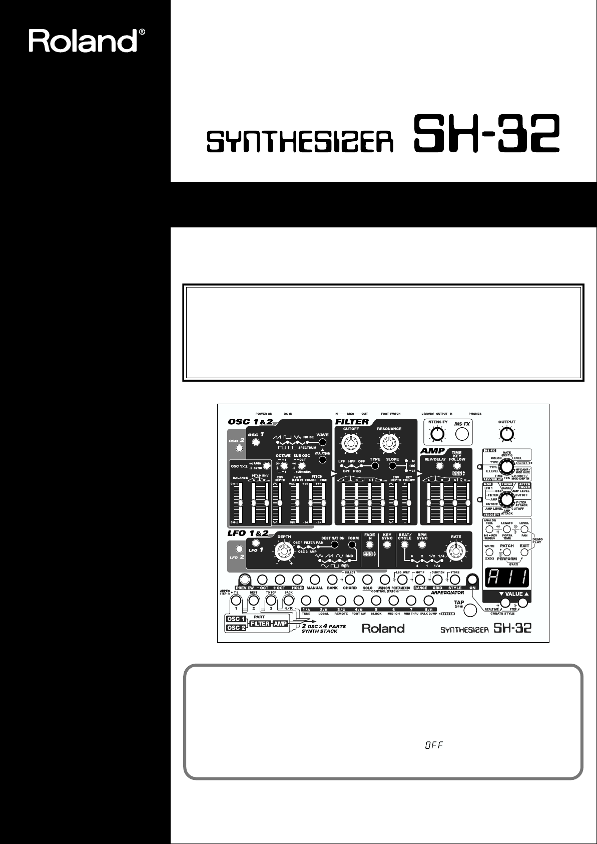
OWNER’S MANUAL
Thank you, and congratulations on your choice of the Roland Synthesizer SH-32.
Before using this unit, carefully read the sections entitled: “USING THE UNIT
SAFELY” and “IMPORTANT NOTES” (p. 2; p. 4). These sections provide important
information concerning the proper operation of the unit. Additionally, in order to
feel assured that you have gained a good grasp of every feature provided by your
new unit, Owner’s Manual should be read in its entirety. The manual should be
saved and kept on hand as a convenient reference.
The SH-32’s
systems with insufficient low end, is set to ON at the factory. When using the SH-32 with
large speakers or a PA, we recommend turning this feature off. Use the following procedure.
1. While holding down [2/B], turn on the SH-32’s power.
2. Press [VALUE ▼] to switch the function to “ ” (Off).
3. Turn the power off, then on again.
Copyright © 2001 ROLAND CORPORATION
All rights reserved. No part of this publication may be reproduced in any form without
the written permission of ROLAND CORPORATION.
Low Boost function
, which compensates for smaller speakers and other
Page 2
For the U.K.
IMPORTANT: THE WIRES IN THIS MAINS LEAD ARE COLOURED IN ACCORDANCE WITH THE FOLLOWING CODE.
BLUE:
BROWN:
As the colours of the wires in the mains lead of this apparatus may not correspond with the coloured markings identifying
the terminals in your plug, proceed as follows:
The wire which is coloured BLUE must be connected to the terminal which is marked with the letter N or coloured BLACK.
The wire which is coloured BROWN must be connected to the terminal which is marked with the letter L or coloured RED.
Under no circumstances must either of the above wires be connected to the earth terminal of a three pin plug.
Used for instructions intended to alert
the user to the risk of death or severe
injury should the unit be used
improperly.
Used for instructions intended to alert
the user to the risk of injury or material
damage should the unit be used
improperly.
* Material damage refers to damage or
other adverse effects caused with
respect to the home and all its
furnishings, as well to domestic
animals or pets.
NEUTRAL
LIVE
The symbol alerts the user to important instructions
or warnings.The specific meaning of the symbol is
determined by the design contained within the
triangle. In the case of the symbol at left, it is used for
general cautions, warnings, or alerts to danger.
The symbol alerts the user to items that must never
be carried out (are forbidden). The specific thing that
must not be done is indicated by the design contained
within the circle. In the case of the symbol at left, it
means that the unit must never be disassembled.
The ● symbol alerts the user to things that must be
carried out. The specific thing that must be done is
indicated by the design contained within the circle. In
the case of the symbol at left, it means that the powercord plug must be unplugged from the outlet.
001
• Before using this unit, make sure to read the instructions
below, and the Owner’s Manual.
........................................................................................................................
002c
• Do not open (or modify in any way) the unit or its AC
adaptor.
........................................................................................................................
003
• Do not attempt to repair the unit, or replace parts within it
(except when this manual provides specific instructions
directing you to do so). Refer all servicing to your retailer,
the nearest Roland Service Center, or an authorized
Roland distributor, as listed on the “Information” page.
........................................................................................................................
004
• Never use or store the unit in places that are:
• Subject to temperature extremes (e.g., direct sunlight
in an enclosed vehicle, near a heating duct, on top of
heat-generating equipment); or are
• Damp (e.g., baths, washrooms, on wet floors); or are
• Humid; or are
• Exposed to rain; or are
• Dusty; or are
• Subject to high levels of vibration.
........................................................................................................................
007
• Make sure you always have the unit placed so it is level
and sure to remain stable. Never place it on stands that
could wobble, or on inclined surfaces.
........................................................................................................................
008c
• Be sure to use only the AC adaptor supplied with the unit.
Also, make sure the line voltage at the installation matches
the input voltage specified on the AC adaptor’s body.
Other AC adaptors may use a different polarity, or be
designed for a different voltage, so their use could result
in damage, malfunction, or electric shock.
........................................................................................................................
009
• Do not excessively twist or bend the power cord, nor place
heavy objects on it. Doing so can damage the cord,
producing severed elements and short circuits. Damaged
cords are fire and shock hazards!
........................................................................................................................
010
• This unit, either alone or in combination with an amplifier
and headphones or speakers, may be capable of
producing sound levels that could cause permanent
hearing loss. Do not operate for a long period of time at a
high volume level, or at a level that is uncomfortable. If
you experience any hearing loss or ringing in the ears, you
should immediately stop using the unit, and consult an
audiologist.
........................................................................................................................
011
• Do not allow any objects (e.g., flammable material, coins,
pins); or liquids of any kind (water, soft drinks, etc.) to
penetrate the unit.
........................................................................................................................
2
Page 3
USING THE UNIT SAFELY
012c
• Immediately turn the power off, remove the AC adaptor
from the outlet, and request servicing by your retailer, the
nearest Roland Service Center, or an authorized Roland
distributor, as listed on the “Information” page when:
• The AC adaptor or the power-supply cord has been
damaged; or
• Objects have fallen into, or liquid has been spilled
onto the unit; or
• The unit has been exposed to rain (or otherwise has
become wet); or
• The unit does not appear to operate normally or
exhibits a marked change in performance.
........................................................................................................................
013
• In households with small children, an adult should
provide supervision until the child is capable of following
all the rules essential for the safe operation of the unit.
........................................................................................................................
014
• Protect the unit from strong impact.
(Do not drop it!)
........................................................................................................................
015
• Do not force the unit’s power-supply cord to share an
outlet with an unreasonable number of other devices. Be
especially careful when using extension cords—the total
power used by all devices you have connected to the
extension cord’s outlet must never exceed the power
rating (watts/amperes) for the extension cord. Excessive
loads can cause the insulation on the cord to heat up and
eventually melt through.
........................................................................................................................
016
• Before using the unit in a foreign country, consult with
your retailer, the nearest Roland Service Center, or an
authorized Roland distributor, as listed on the “Information” page.
........................................................................................................................
101b
• The unit and the AC adaptor should be located so their
location or position does not interfere with their proper
ventilation.
........................................................................................................................
102d
• Always grasp only the plug or the body of the AC adaptor
when plugging into, or unplugging from, an outlet or this
unit.
........................................................................................................................
103b
• Whenever the unit is to remain unused for an extended
period of time, disconnect the AC adaptor.
........................................................................................................................
104
• Try to prevent cords and cables from becoming entangled.
Also, all cords and cables should be placed so they are out
of the reach of children.
........................................................................................................................
106
• Never climb on top of, nor place heavy objects on the unit.
........................................................................................................................
107d
• Never handle the AC adaptor body, or its plugs, with wet
hands when plugging into, or unplugging from, an outlet
or this unit.
........................................................................................................................
108b
• Before moving the unit, disconnect the AC adaptor and all
cords coming from external devices.
........................................................................................................................
109b
• Before cleaning the unit, turn off the power and unplug
the AC adaptor from the outlet (p. 17).
........................................................................................................................
110b
• Whenever you suspect the possibility of lightning in your
area, disconnect the AC adaptor from the outlet.
........................................................................................................................
3
Page 4
IMPORTANT NOTES
In addition to the items listed under “USING THE UNIT SAFELY” on page 2, please read and observe the following:
Power Supply
301
• Do not use this unit on the same power circuit with any device
that will generate line noise (such as an electric motor or variable
lighting system).
302
• The AC adaptor will begin to generate heat after long hours of
consecutive use. This is normal, and is not a cause for concern.
307
• Before connecting this unit to other devices, turn off the power to
all units. This will help prevent malfunctions and/or damage to
speakers or other devices.
Placement
352a
• This device may interfere with radio and television reception. Do
not use this device in the vicinity of such receivers.
352b
• Noise may be produced if wireless communications devices, such
as cell phones, are operated in the vicinity of this unit. Such noise
could occur when receiving or initiating a call, or while
conversing. Should you experience such problems, you should
relocate such wireless devices so they are at a greater distance
from this unit, or switch them off.
355
• To avoid possible breakdown, do not use the unit in a wet area,
such as an area exposed to rain or other moisture.
Maintenance
401a
• For everyday cleaning wipe the unit with a soft, dry cloth or one
that has been slightly dampened with water. To remove stubborn
dirt, use a cloth impregnated with a mild, non-abrasive detergent.
Afterwards, be sure to wipe the unit thoroughly with a soft, dry
cloth.
402
• Never use benzine, thinners, alcohol or solvents of any kind, to
avoid the possibility of discoloration and/or deformation.
Repairs and Data
452
• Please be aware that all data contained in the unit’s memory may
be lost when the unit is sent for repairs. Important data should
always be backed up in another MIDI device (e.g., a sequencer).
During repairs, due care is taken to avoid the loss of data.
However, in certain cases (such as when circuitry related to
memory itself is out of order), we regret that it may not be possible
to restore the data, and Roland assumes no liability concerning
such loss of data.
Memory Backup
501b
• This unit contains a battery which powers the unit’s memory
circuits while the main power is off. When this battery becomes
weak, the message shown below will appear in the display. Once
you see this message, have the battery replaced with a fresh one as
soon as possible to avoid the loss of all data in memory. To have
the battery replaced, consult with your retailer, the nearest Roland
Service Center, or an authorized Roland distributor, as listed on
the “Information” page.
Additional Precautions
551
• Please be aware that the contents of memory can be irretrievably
lost as a result of a malfunction, or the improper operation of the
unit. To protect yourself against the risk of loosing important data,
we recommend that you periodically save a backup copy of
important data you have stored in the unit’s memory in another
MIDI device (e.g., a sequencer).
552
• Unfortunately, it may be impossible to restore the contents of data
that was stored in the unit’s memory, or other device (e.g., a
sequencer) once it has been lost. Roland Corporation assumes no
liability concerning such loss of data.
553
• Use a reasonable amount of care when using the unit’s buttons,
sliders, or other controls; and when using its jacks and connectors.
Rough handling can lead to malfunctions.
556
• When connecting / disconnecting all cables, grasp the connector
itself—never pull on the cable. This way you will avoid causing
shorts, or damage to the cable’s internal elements.
558a
• To avoid disturbing your neighbors, try to keep the unit’s volume
at reasonable levels. You may prefer to use headphones, so you do
not need to be concerned about those around you (especially
when it is late at night).
559a
• When you need to transport the unit, package it in the box
(including padding) that it came in, if possible. Otherwise, you
will need to use equivalent packaging materials.
• In order to fully broaden the range of expression that is possible
from its sounds, the SH-32 makes it possible to make settings for a
wider range of parameters than those offered by an ordinary
sound module. When turning up the filter resonance, effect
feedback, or other parameters to extreme levels, reduce the
volume so as not to overload the equipment used for playback.
• Since some of the Preset Patches were designed with a specific
purpose in mind, they sound best if played within the appropriate
range, or with suitable phrases. Such sounds may get distorted
if played outside the intended range. When changing the
register or phrase being used, reset the parameters for your sound
so that such distortion is avoided.
• About reception of MIDI messages while the Arpeggiator is
functioning
• Internally, the SH-32 gives priority to the sound processing
that uses the Wave Acceleration method. Due to the limitations of the system, demands for the processing of large
amounts of data for additional functions other than those
related to the sound generation section (such as for the
Arpeggiator or certain kinds of MIDI messages) may
prevent the SH-32 from operating correctly.
• If a large volume of Control Change or Aftertouch messages
are transmitted while the Arpeggiator is being used, or
otherwise when numerous voices are sounding, processing for
the sound generator is given priority. As a result, the Arpeggiator may stop working correctly, or the tempo may not be
maintained. In particular, you should be careful with consecutive streams of densely packed MIDI messages, which is
what devices other than the SH-32 may sometimes be sending.
“” (Battery Low)
4
Page 5
How To Use This Manual
This owner’s manual is organized as follows.
Quick Start
For those who are using the SH-32 for the first time, this section
provides a simple explanation of how to use and enjoy various
functions. Please read the “Quick Start” and follow along by actually
operating the SH-32. This will help you understand most of what
you need to know for basic operations. More advanced ways of
using the SH-32 or details of other operations are explained in the
“Advanced Use” section.
Advanced Use
The “Advanced Use” section is divided into 9 chapters. Before you
read this manual, you should read through the “Quick Start” manual
so you’re familiar with the basic operation of the unit.
Chapter 1. An Overview of the SH-32
This chapter explains how the SH-32 is organized, the available
memory locations, and the differences among settings depending on
the mode. Reading it is essential for understanding SH-32
operational procedures.
Chapter 2. Creating Your Own Sounds
This chapter explains how SH-32 sounds are created, together with a
description of how the parameters are organized. Comprehending
the information in the chapter is an essential prerequisite before
creating your own sounds.
Chapter 3. Applying Effects to the
Sound (INS-FX, REV/DELAY)
This chapter explains how to make settings for the SH-32’s onboard
effects. Be sure to read this when adding effects to Patches and
Performances.
Chapter 4. Playing the Rhythm Sets
This chapter explains how to play and create Rhythm Sets. Read this
chapter when using Rhythm Sets.
Chapter 7. Using the Chord Memory
Function (CHORD)
This chapter explains how to use and make settings for the Chord
Memory function. Read this chapter when using the Chord Memory
function.
Chapter 8. Using the SH-32 with
External MIDI Devices
This chapter provides a description of MIDI, and explains how to
use an external MIDI device to switch sounds, save settings onto
external devices, and carry out other tasks. Read this material as
necessary.
Chapter 9. Other Settings
This chapter explains how to set the system parameters, which
determine the SH-32’s operational environment, as well as the
parameter functions, how to restore the default factory settings, and
other related information. Read this material as necessary.
Appendices
This chapter contains a troubleshooting section for use when the SH32 is not functioning as expected. There is also a list of error
messages that you can refer to if an error message appears on the
display. This chapter also contains information such as Patch/
Rhythm Set/Performance lists, parameter lists and the MIDI
implementation chart.
Notation Used in This Owner’s Manual
To make operation procedures easy to understand, the following
notation system is adopted:
Characters and numbers in square brackets [ ] indicate knobs and
buttons on the front panel. For example, [CUTOFF] represents the
CUTOFF knob and [PREVIEW] stands for the PREVIEW button.
(p. **) refers to pages within the manual.
Below are the meanings of the symbols preceding certain sentences
in the text.
Chapter 5. Using in Performance Mode
This chapter explains how to play and create Performances. Read
this chapter when you wish to use Performances.
Chapter 6. Using Arpeggiator
(ARPEGGIATOR)
This chapter explains how to use and make settings for the
Arpeggiator, how to create Styles, and other related information.
Read this chapter when you wish to use the arpeggiator.
These are notes. Please be sure to read them.
These are reference memos. Read these as necessary.
These are hints for operating the SH-32. Read these as necessary.
These provide information from related reference pages. Read
these as necessary.
5
Page 6

Contents
IMPORTANT NOTES ...............................................................................4
How To Use This Manual........................................................................5
Notation Used in This Owner’s Manual...................................................................................... 5
Main Features........................................................................................11
Panel Descriptions................................................................................12
Front Panel.................................................................................................................................................12
Rear Panel.................................................................................................................................................. 15
Getting Ready........................................................................................16
Connecting External Devices.................................................................................................................. 16
Turning On the Power............................................................................................................................. 17
Turning Off the Power ................................................................................................................. 17
Restoring the Factory Settings (Factory Reset).....................................................................................17
Listening to the Demo Songs..................................................................................................................18
Quick Start...................................19
Producing Sound..................................................................................20
Getting Started.......................................................................................................................................... 20
About the Playing Modes of the SH-32 (PATCH/PERFORMANCE)..................................20
Switching Modes...........................................................................................................................20
Standalone Play of Sounds (PREVIEW)................................................................................................21
Playing a Sound with a MIDI Keyboard...............................................................................................22
Listening to the Preset Sounds ............................................................................................................... 23
Using the Effects....................................................................................................................................... 24
Playing a Rhythm Set............................................................................................................................... 25
Modifying the Sound ............................................................................26
Creating Sounds .......................................................................................................................................26
Easy Sound Editing.................................................................................................................................. 27
1. Selecting a Waveform (Oscillator).......................................................................................... 27
2. Working on Oscillator Waveforms (FILTER) .......................................................................29
3. Adding Changes in the Volume (AMP) ................................................................................31
4. Adding Modulation to the Sound (LFO)............................................................................... 32
5. Adding an Effect .......................................................................................................................34
Saving the Sound......................................................................................................................................35
Playing Arpeggio (Arpeggiator)...........................................................36
Turning On/Off the Arpeggiator...........................................................................................................36
Changing the Arpeggiator Tempo.........................................................................................................38
Playing the Arpeggio Together with a Rhythm Pattern.....................................................................39
Playing a Chord at the Touch of a Finger (Chord Memory)..............41
Using the Chord Memory Function.......................................................................................................41
Switching Chord Forms........................................................................................................................... 42
6
Page 7

Contents
Advanced Use ..............................43
Chapter 1. An Overview of the SH-32..................................................44
How the SH-32 is Organized Internally................................................................................................44
MIDI Connectors...........................................................................................................................44
Sound Generator ........................................................................................................................... 44
Arpeggiator....................................................................................................................................44
Controller ....................................................................................................................................... 44
Patches, Rhythm Sets, and Performances.............................................................................................45
Patches (A11–D88) ........................................................................................................................ 45
Rhythm Sets (r1U, r2U, r3P, r4P)................................................................................................45
Performances (1-1–8-8)................................................................................................................. 46
How Characters and Numerals Are Displayed................................................................................... 46
About Memory..........................................................................................................................................47
Temporary Memory......................................................................................................................47
Rewritable Memory......................................................................................................................47
Non-Rewritable Memory............................................................................................................. 47
Main Setting Destinations............................................................................................................48
Objects of Settings That Change with the SH-32’s Mode...................................................................50
Chapter 2. Creating Your Own Sounds...............................................52
Creating Sounds that Reflect the Position of Sliders/Knobs (MANUAL).......................................52
Using Preview Function Hold to Continue Playing a Sound............................................................ 52
Determining the Basic Waveform and Pitch (OSC 1 & 2) .................................................................. 52
Oscillator ON/OFF and Mix Balance (OSC 1, OSC 2, BALANCE)....................................... 52
Selecting the Fundamental Waveform (WAVE, VARIATION) ............................................. 53
Determining the Pitch (OCTAVE, PITCH)................................................................................ 54
Creating a Fatter Sound by Adding Components One Octave Below the Sound
(SUB OSC)......................................................................................................................................54
Changing the Pitch Over Time (PITCH ENV, ENV DEPTH)................................................. 54
Changing the Pulse Width of a Square Wave Periodically (PWM).......................................55
Creating a Metallic Sound (OSC 1X2 RING)—Ring Modulator ............................................ 55
Creating an Assertive Solo Sound (OSC 1X2 SYNC)—Oscillator Sync ................................ 55
Changing the Characteristics of Sounds (FILTER).............................................................................. 56
Internal Filter Types and Functions (TYPE, SLOPE) ............................................................... 56
Setting the Cutoff Frequency (CUTOFF)................................................................................... 57
Using Resonance to Add Fullness to the Sound (RESONANCE).......................................... 57
Changing the Cutoff Over Time (A D S R, ENV DEPTH) ...................................................... 57
Changing the Filter According to the Keyboard Position (KEY FOLLOW)......................... 58
Changing the Volume (AMP).................................................................................................................58
Changing the Volume Over Time (A D S R, ENV DEPTH)....................................................58
Increasing and Decreasing the Rate of Change in Volume According to the Keyboard
Position (TIME KEY FOLLOW).................................................................................................. 59
Setting the Volume for Each Patch, Rhythm Set, or Performance.........................................59
Modulating the Sound (LFO 1 & 2) ....................................................................................................... 59
LFO Arrangement and Functions...............................................................................................59
Turning the LFO On and Off, and Switching Waveforms (LFO 1, LFO 2, FORM)............. 59
Adjusting the Rate of Modulation (RATE)................................................................................ 60
Adjusting the Modulation Depth (DESTINATION, DEPTH)................................................60
Synchronizing the Modulation to the Song Tempo (BPM SYNC, BEAT/CYCLE)............. 61
Other LFO Settings (FADE IN, KEY SYNC) ............................................................................. 61
7
Page 8

Contents
Other Settings (settings that can be saved to Patches)........................................................................ 61
Settings for Use in Playing Monophonic Sounds (SOLO, LEGATO)....................................61
Layering Sounds for Greater Fatness (UNISON)..................................................................... 62
Applying the Portamento Function (PORTAMENTO, PORTA TIME)................................62
Applying Analog-Like Modulation to the Pitch (ANALOG FEEL)......................................62
Changing the Pan When Using Stereo Output (PAN) ............................................................ 63
Effect Settings ................................................................................................................................63
Saving the Sounds You Have Created (WRITE)..................................................................................63
Auditioning to a Patch at the Save Destination........................................................................63
Chapter 3. Applying Effects to the Sound (INS-FX, REV/DELAY) ....64
About the Onboard Effects .....................................................................................................................64
Ways of Connecting Effects (INS > REV SERIES).................................................................... 64
Using the Insertion Effects (INS-FX)......................................................................................................64
Turning the Insertion Effects On and Off..................................................................................64
Selecting the Insertion Effects Type (TYPE)..............................................................................64
Setting the Insertion Effects......................................................................................................... 65
Using the Reverb/Delay (REV/DELAY)..............................................................................................65
Turning the Reverb/Delay On and Off.....................................................................................65
Selecting the Reverb/Delay Type (TYPE).................................................................................65
Setting the Reverb/Delay ............................................................................................................ 66
Applying Effects in Performance Mode................................................................................................66
Selecting the Effect Settings Used in a Performance (Effect Source).....................................66
About Effect Settings in Performance Mode.............................................................................67
Chapter 4. Playing the Rhythm Sets ...................................................68
Selecting Rhythm Sets and Playing the Percussion Instruments ...................................................... 68
Editing a Rhythm Set...............................................................................................................................68
Making Settings for the Overall Rhythm Set ............................................................................ 68
Making Settings for Each Rhythm Tone (Percussion Instrument) ........................................69
Saving Changed Settings (WRITE)........................................................................................................70
Chapter 5. Using in Performance Mode..............................................71
Selecting a Performance and Playing the Patch for Each Part...........................................................71
Selecting the Patch for Each Part (Part Assign Mode).............................................................71
Playing Sound in More Than One Part (Multitimbre)........................................................................ 71
Layering Patches for a Thicker Sound (Part Stack Function).............................................................72
Editing a Performance ............................................................................................................................. 72
Settings Affecting the Overall Performance..............................................................................72
Making Settings for Each Patch or Rhythm Set in the Parts...................................................73
Securing the Number of Oscillators in Each Part (Oscillator Reserve).................................73
Saving Changed Settings (WRITE)........................................................................................................73
Chapter 6. Using Arpeggiator (ARPEGGIATOR)................................74
About Arpeggiator................................................................................................................................... 74
Playing Arpeggios....................................................................................................................................74
Turning Arpeggiator On and Off ...............................................................................................74
Determining the Tempo for Arpeggio Performances..............................................................74
Selecting Styles for Arpeggio Performances (STYLE) .............................................................74
The Relationship Between Arpeggio Styles and Rhythm Styles............................................ 75
Changing the Beat and Shuffle (GRID)......................................................................................75
Applying Staccato and Tenuto (DURATION)..........................................................................76
Changing the Range of the Arpeggio (RANGE) ...................................................................... 76
Selecting Ascending/Descending Variations (Different Ways of Playing the Sounds)
(MOTIF).......................................................................................................................................... 76
8
Page 9

Contents
Creating Your Own Styles.......................................................................................................................77
Creating Styles by Playing the Notes as They Are to Be Performed (REALTIME)............. 77
Creating Styles by Playing Sounds One At a Time (STEP).....................................................78
Creating Styles Using an External Sequencer........................................................................... 79
Saving the Styles You Have Created (STORE) ......................................................................... 79
Using Arpeggiator in Performance Mode ............................................................................................ 80
Selecting the Style .........................................................................................................................80
Specifying the Part Used to Play the Arpeggio ........................................................................ 80
Arpeggiator Parameter Settings..................................................................................................80
Creating Styles...............................................................................................................................80
Chapter 7. Using the Chord Memory Function (CHORD)..................81
About the Chord Memory Function......................................................................................................81
Performing with the Chord Memory Function.................................................................................... 81
Turning Chord Memory Function On and Off.........................................................................81
Selecting Chord Forms.................................................................................................................81
Creating Your Own Chord Forms.............................................................................................. 82
Using the Chord Memory Function in Performance Mode...............................................................82
Selecting the Chord Form ............................................................................................................ 82
Specifying the Part to Use the Chord Memory Function........................................................ 82
Chord Memory Parameter Settings............................................................................................ 83
Creating Chord Forms.................................................................................................................. 83
Chapter 8. Using the SH-32 with External MIDI Devices ...................84
About MIDI...............................................................................................................................................84
MIDI Connectors...........................................................................................................................84
About MIDI Channels..................................................................................................................84
Setting the MIDI Channel (MIDI CH)...................................................................................................84
Setting the Receive Channel in Patch Mode..............................................................................84
Setting the Receive Channel for Each Part ................................................................................ 84
Playing the SH-32 from an External MIDI Keyboard ......................................................................... 85
Changing the Sound with Modulation (MOD) ........................................................................85
Determining the Amount the Pitch is Changed with the Pitch Bender (P. BEND).............86
Changing the Sound with Aftertouch (AFTERTOUCH) ........................................................ 86
Changing the Sound According to the Force Used to Play the Keys (VELOCITY) ............ 87
Selecting SH-32 Sounds from an External MIDI Device..................................................................... 87
Synchronizing Arpeggiator and the LFO to an External MIDI Device............................................88
Saving SH-32 Settings on an External Sequencer (BULK DUMP) .................................................... 88
Restoring Saved Content to the SH-32.......................................................................................89
Chapter 9. Other Settings.....................................................................90
Settings Applied to the SH-32 Overall (System Settings)...................................................................90
Procedure for Making the System Settings ............................................................................... 90
What the System Settings Do/System Setting Functions .......................................................90
Switching the Low Boost Function On and Off........................................................................92
Selecting the Status to Use When the Power is Turned On....................................................93
Selecting the MIDI Messages Used to Transmit Panel Control Information ....................... 93
Changing the SH-32’s Device ID Number.................................................................................93
Restoring the Factory Settings (Factory Reset).....................................................................................94
9
Page 10

Contents
Appendices ..................................95
Troubleshooting....................................................................................96
Error Message List................................................................................98
Patch List...............................................................................................99
Rhythm Set List...................................................................................100
Performance List.................................................................................101
Arpeggio Style List .............................................................................102
Rhythm Style List................................................................................103
Chord Form List..................................................................................104
Parameter List.....................................................................................105
Patch Parameters....................................................................................................................................105
Rhythm Set Parameters ......................................................................................................................... 106
Performance Parameters .......................................................................................................................106
System Parameters ................................................................................................................................. 106
Effects List...........................................................................................107
Insertion Effects Parameters ................................................................................................................. 107
Reverb/Delay Parameters..................................................................................................................... 113
MIDI Transmit/Receive Setting List...................................................115
MIDI Implementation Chart ................................................................116
Specifications......................................................................................117
Index.....................................................................................................118
Blank Chart..........................................................................................121
10
Page 11
Main Features
PART 1
PART 2
PART 3
PART 4 / RHYTHM
FILTER AMP
LFO2
OSC 1
SUB OSC
OSC 2
SUB OSC
MIX/
RING/
SYNC
ENV
ENVENV
LFO1
ARPEGGIATOR
(PROGRAMMABLE)
BPM SYNC
PREVIEW
/CHORD MEMORY
INS-FX
2 x EFFECTS
REV/DELAY
TO ARPEGGIATOR
● Rich Sound with Full Synth Presence
Development of the SH-32 has involved a variety of approaches to
thoroughly analyze synthesizer sounds in order to realize the “fat,
sharp, clear sound” that is characteristic of analog synths.
To quantify these sound characteristics, various measurements and
blind tests using renowned vintage synths, analog modeling synths,
and other gear were carried out. The findings of such research
formed the basis for designing our new Wave Acceleration Sound
Generator(*), which is capable of the complete realization of the
sound variations and qualities of a synthesizer. This allows you to
produce vintage synth sounds and a wide variety of other
waveforms, all with this one instrument.
The SH-32 synthesizer offers not only the sounds being demanded
on today’s music scene, but also provides the convenient operation
that you get only with a digital unit.
* This is a new approach to sound generation that permits creation of a
wide variety of high-quality waveforms, while featuring numerous
oscillators, something impossible with simple DSP synths.
● Full Freedom to Create Your Own
Unique Sounds
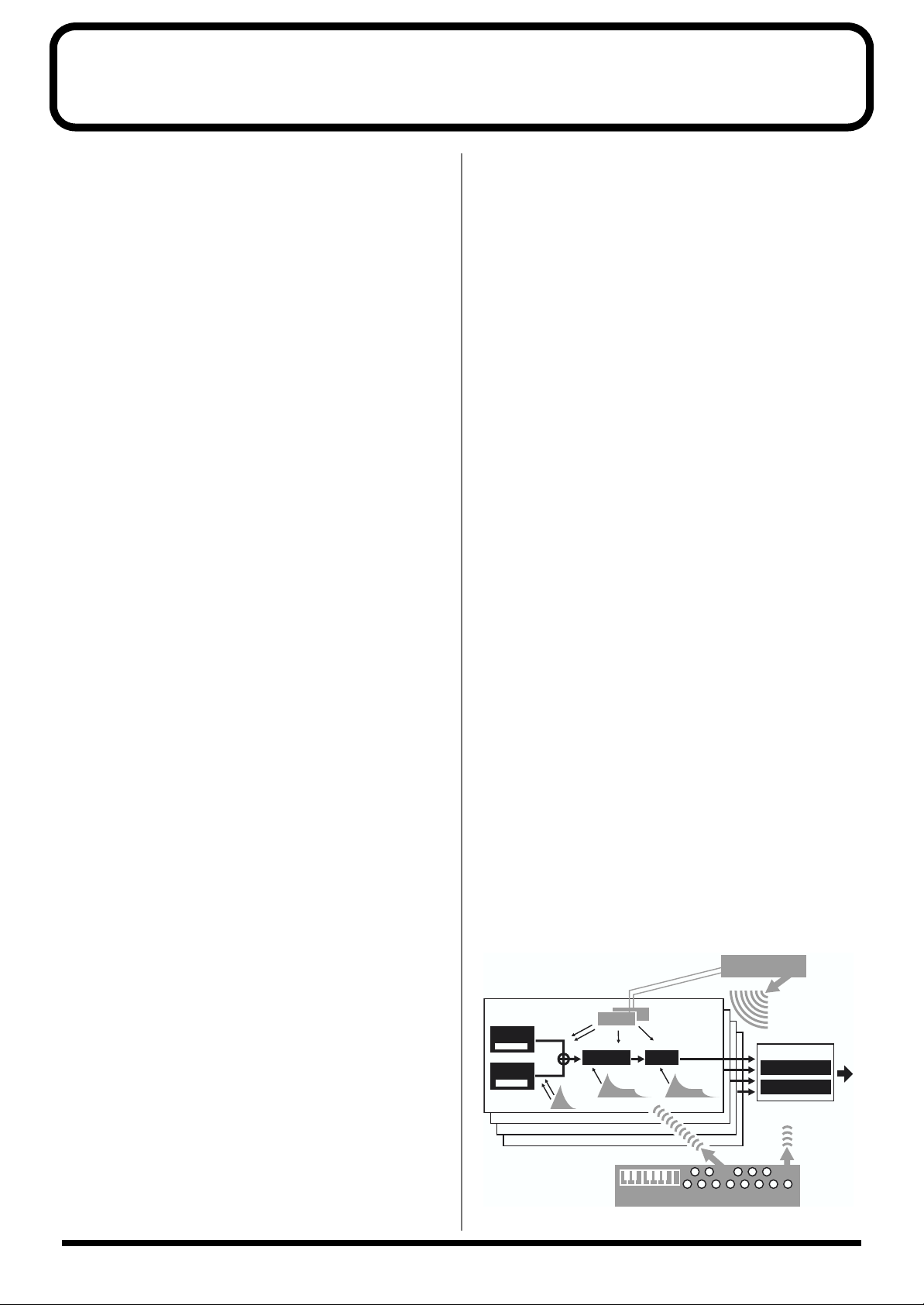
With the architecture of the SH-32’s sound generator, you get two
oscillators, one filter, an amp, and two LFOs for each sound, all
controlled with an analog synth-like interface. The great freedom in
creating sounds presented by this synthesizer means that you are
likely to truly enjoy the sound creation process.
Each of the seven groups of waveforms, SAW, SQUARE, PULSE,
PWM, TRIANGLE/SINE, SPECTRUM and NOISE, which comprise
the foundation for creating sounds, also contains a number of
variation waveforms, each featuring a different character. With a
total of 67 different oscillator waveforms at your fingertips, the SH32 makes it possible for you to create sounds unlike any others.
The SH-32 also includes four Rhythm Sets (two Preset and two User)
that feature TR-909/808 and other drum waveforms. With 32
oscillators, far surpassing previous analog modeling synths, and
four-part multitimbral sound, you can create songs that combine
synth parts and rhythm part, all with one machine.
What’s more, the SH-32 is also packed with a variety of useful
features and functions for creating sounds, including a Suboscillator
with subsonic mode (which makes it easy to add more to the low
end), Oscillator Sync, a Ring Modulator, synchronization of the LFO
to the tempo using the TAP button, and more. Whether it be the
sounds of some of the most popular synthesizers, or sounds that
were once very difficult to create using conventional analog and DSP
synths, you can handle them all, since the sound creation potential
you now have at your fingertips is enormous.
● Built-In Effect Functions Help Create
a More Polished Sound
The SH-32 is equipped with internal effects processors that help
make this a complete synthesizer module. You can use effects from
two systems: 35 individual Insertion Effects, including distortion,
phaser, flanger, and other effects, and 10 different kinds of reverb
and delay (loop effects), allowing you to create an even greater
variety of sounds.
● Programmable Arpeggiator Brings
Out the Power in Your Performances
The SH-32 includes an Arpeggiator function, which allows the user
to program Styles. Styles can be input in steps or in real time. In
Performance mode, you can have arpeggios using the synth sounds
played along with rhythm patterns that use TR-909/808 and other
drum waveforms.
In addition, you can easily play a variety of complex chords, like
those used in Trance and Techno music, in parallel by using this
feature in combination with the Chord Memory function, which
allows you to perform prerecorded chords with the press of a single
button.
● Panel Designed for Intuitive
Operation
The SH-32 features an intuitive panel design that lets you
concentrate on creating sounds. For example, knobs are used for the
filter, and sliders for the envelope; in all cases, the most convenient
control for the purpose is used.
In addition, the panel includes thirteen buttons that can be used for
note-entry, much like a keyboard. Using the Preview function, you
can check your sounds over a scale of notes, without having to
connect a MIDI keyboard.
On top of this, the SH-32’s compact desktop design means you can
always have it at hand, ready to use. Use it with PCs, workstations,
keyboards, groove gear and other equipment to bring out the full
potential of this synthesizer, regardless of the application.
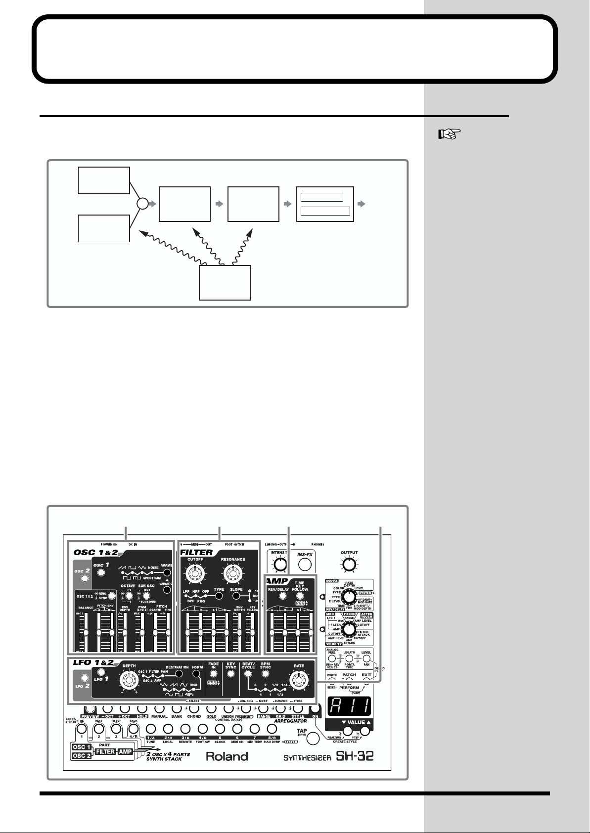
SH-32 Block Diagram (Conceptual)
fig.SH-32 block
11
Page 12
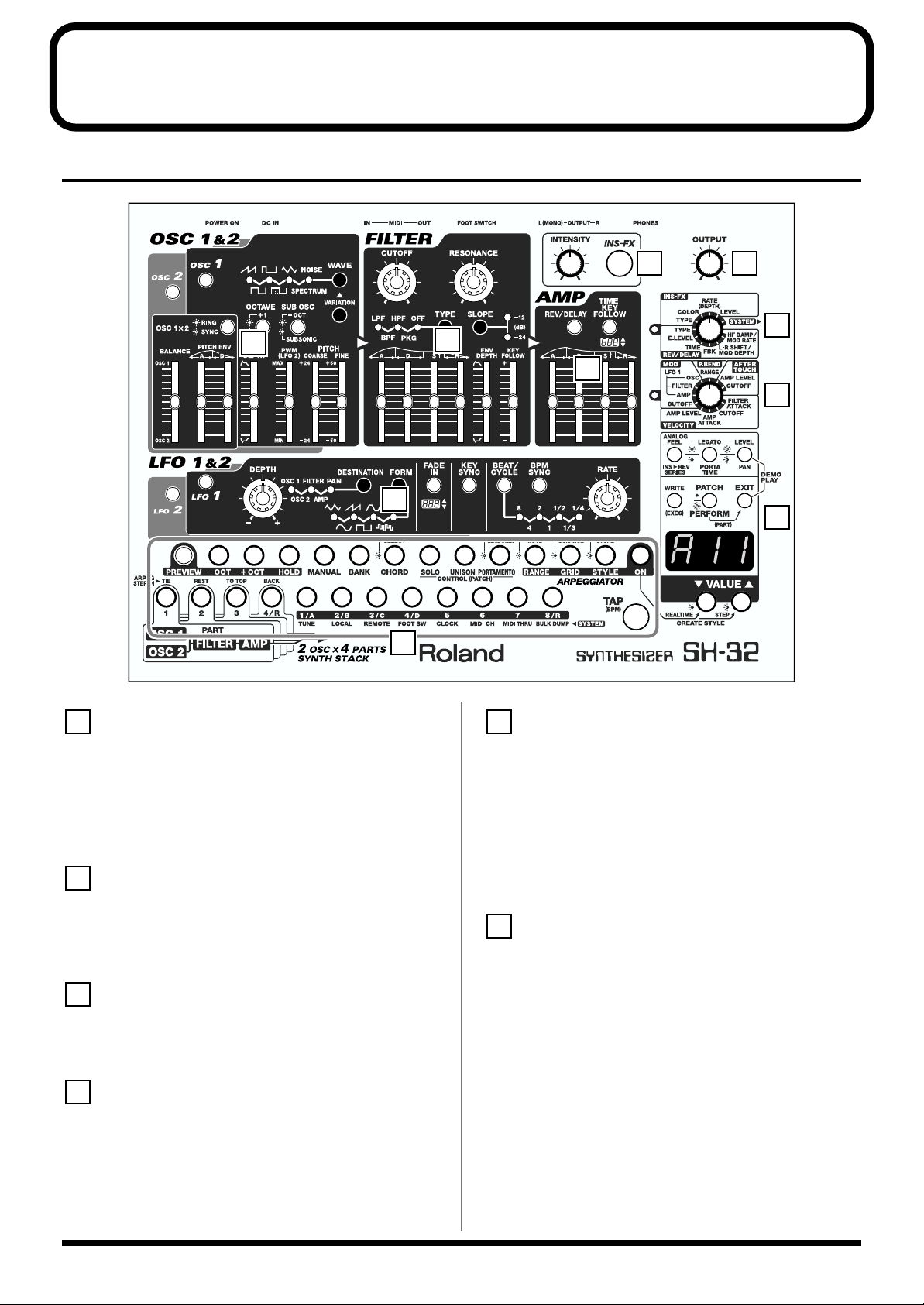
Panel Descriptions
5
6
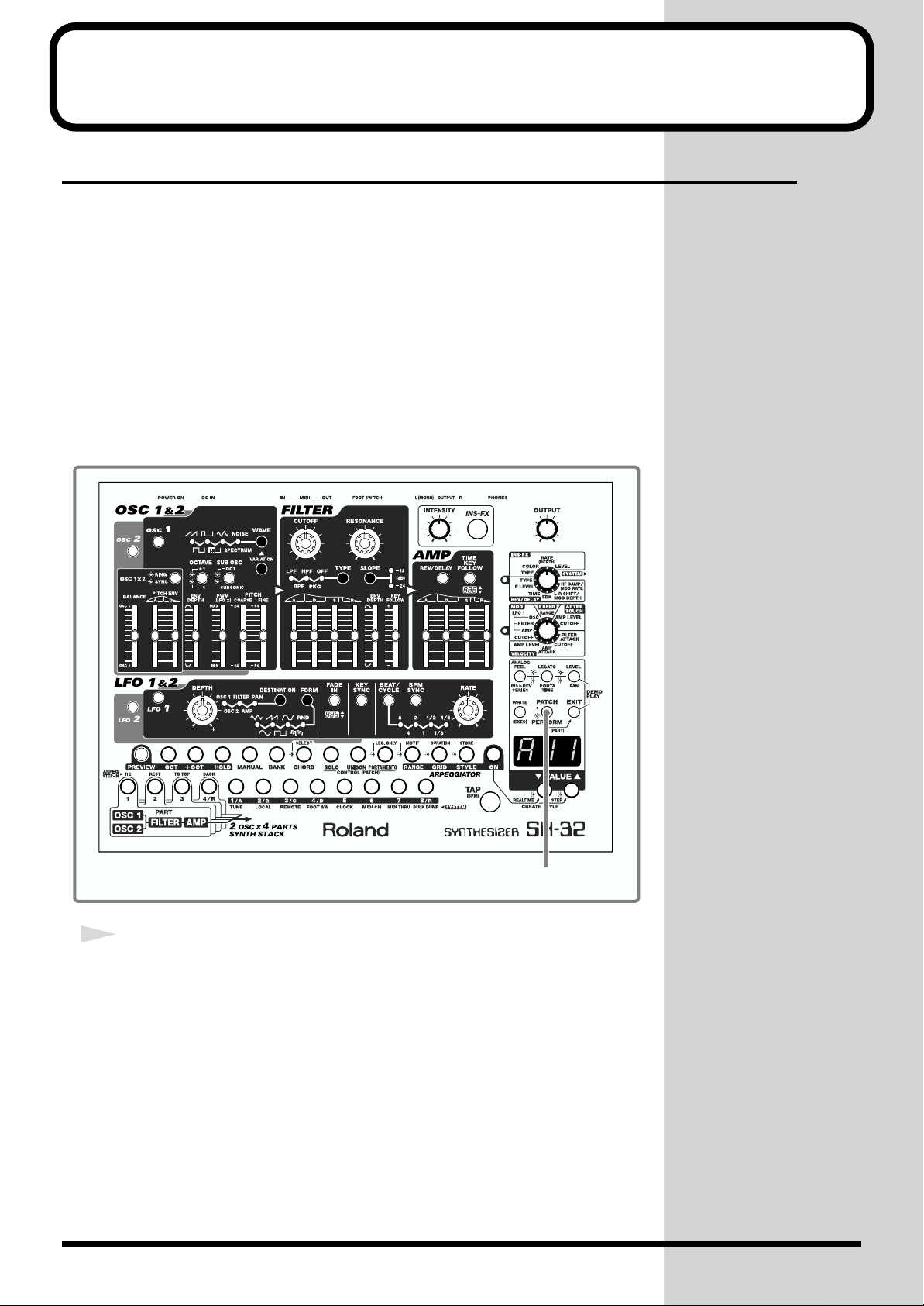
Front Panel
fig.00-02
5 6
1
4
10
1
OSC 1 & 2 (Oscillator 1 & 2)
Section
Select the waveforms on which sounds are based, and adjust the
pitch and other components of the sound. In addition, you can
combine OSC 1 and OSC 2 to create a wide variety of sounds. → (p.
52)
2
FILTER Section
2
7
3
8
9
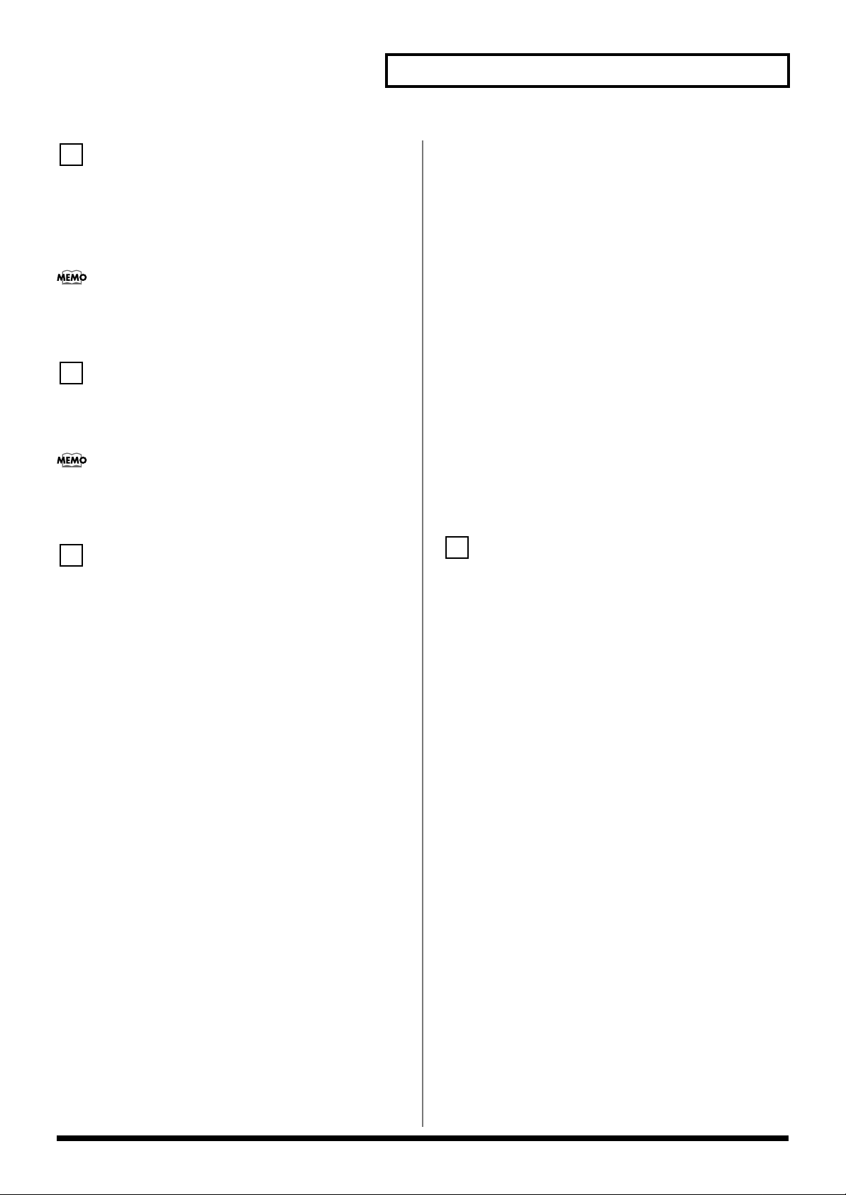
[INTENSITY]
Change the settings values of the Insertion Effects parameters. The
parameters that can be set vary according to the selected Insertion
Effects. → (p. 65)
[INS-FX]
Switches the Insertion Effects on and off. → (p. 64)
Change the type of filter used, and alter the characteristics of the
sound by making various changes to the output waveforms. → (p.
56)
[OUTPUT]
3
AMP (Amplifier) Section
Alter the sound by changing the volume and the way sounds are
output and muted. → (p. 58)
4
LFO 1 & 2 (Low Frequency
Adjusts the overall volume that is output from the rear panel
OUTPUT jacks and PHONES jack. → (p. 17)
Oscillator 1 & 2) Section
Use the LFO 1 and 2 waveforms to create cyclic changes in the pitch,
brightness, volume, and other aspects of the sounds produced by the
waveforms from OSC 1 and OSC 2. → (p. 59)
12
Page 13
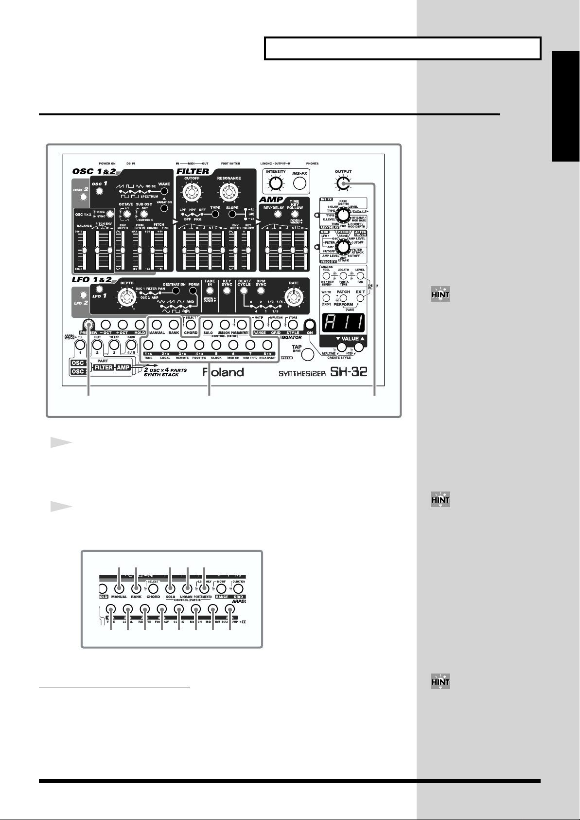
Panel Descriptions
10
7
FX/SYSTEM Knob
Selects the “INS-FX” (Insertion Effects) or “REV/DELAY” (Reverb/
Delay) parameters to be set. → (p. 65, p. 66)
When this is set to “SYSTEM,” you can make changes to the settings
that govern the SH-32’s overall behavior (system parameters). → (p.
90)
When you select a parameter for which you want to make
settings, the indicator on the left begins to blink, indicating that
the SH-32 is ready for changes in the settings.
8
MIDI Settings Knob
Selects the parameter to be set when modifying sounds as the result
of messages (Modulation, Pitch Bend, Aftertouch, Velocity) received
from an external MIDI device. → (p. 85)
When you select a parameter for which you want to make
settings, the indicator on the left begins to blink, indicating that
the SH-32 is ready for changes in the settings.
9
[ANALOG FEEL]/[INS > REV SERIES]
ANALOG FEEL: Press this button, causing the indicator to light, to
set the degree to which analog-like modulation is applied to the
pitch. → (p. 62)
INS > REV SERIES: Press this button, causing the indicator to blink,
to select the way the Insertion Effects and Reverb/Delay are
connected. → (p. 64)
[LEGATO]/[PORTA TIME]
LEGATO: Press this button, causing the indicator to light, to turn the
Legato function on and off. → (p. 61)
PORTA TIME: Press this button, causing the indicator to blink, to set
the time over which the pitch changes when playing portamento. →
(p. 62)
[LEVEL]/[PAN]
LEVEL: Press this button, causing the indicator to light, to set the
volume of the Patch or Performance. → (p. 59)
PAN: Press this button, causing the indicator to blink, to set the
panning. → (p. 63)
Additionally, when used simultaneously with [EXIT], this allows
you to listen to the demo songs. → (p. 18)
[WRITE (EXEC)]
This is pressed when saving (WRITE) tone, Arpeggiator, and other
settings, or when executing (EXEC) various functions.
[PATCH]/[PERFORM]
PATCH: Press this button, causing the indicator light to go off, to
switch to Patch mode. → (p. 20)
PERFORM: Press this button, causing the indicator to light, to
switch to Performance mode. When in Performance mode, hold
down [PERFORM] and press [EXIT] to switch to Part Assign mode.
→ (p. 20, p. 71)
[EXIT]
Pressed to cancel settings and other various operations.
Additionally, when used simultaneously with [LEVEL/PAN], this
allows you to listen to the demo songs. → (p. 18)
Display
A variety of information, including the number of the selected sound
and the values of various parameter settings, is displayed here.
[VALUE ▼/▲]
These change the various settings values.
To rapidly increase the value, hold down [▲] and press [▼].
To rapidly decrease the value, hold down [▼] and press [▲].
[PREVIEW]
Switches the Preview function on and off. → (p. 21)
[-OCT], [+OCT]
These shift the register played using the Preview function in octave
units. → (p. 21)
[HOLD]
Switches the Preview function’s Hold On and Hold Off. → (p. 21)
[MANUAL]
Switches the Manual function on and off. → (p. 52)
[BANK]
This is pressed when tone banks and numbers are switched. → (p.
23)
[CHORD]
Switches the Chord Memory function on and off. → (p. 81)
[SOLO]
Switches the Solo function on and off. → (p. 61)
[UNISON]
Switches the Unison function on and off. → (p. 62)
[PORTAMENTO]/[LEG. ONLY]
PORTAMENTO: Press this button, causing the indicator to light, and
portamento will be turned on. → (p. 62)
LEG. ONLY: Press this button, causing the indicator to blink, to use
portamento only when playing legato. → (p. 62)
13
Page 14
Panel Descriptions
[RANGE]/[MOTIF]
RANGE: Press this button, causing the indicator to light, to set, in
octave units, the range in which arpeggios are played. → (p. 76)
MOTIF: Press this button, causing the indicator to blink, to select the
arpeggio variation to be played during arpeggio performances. → (p.
76)
[GRID]/[DURATION]
GRID: Press this button, causing the indicator to light, to select the
timing used to sound arpeggios during arpeggio performances. →
(p. 75)
DURATION: Press this button, causing the indicator to blink, to
select the note length used to play arpeggios during arpeggio
performances. → (p. 76)
[STYLE]/[STORE]
STYLE: Press this button, causing the indicator to light, to select the
basic style used to play arpeggios. → (p. 74)
STORE: Press this button, causing the indicator to blink, to save the
arpeggio styles you have created. → (p. 79)
About the Symbols on the Panel
The following symbols, which appear on the SH-32’s panel, are
meant to depict the illumination state of the indicators.
: Lit
: Blinking
: Off
[ON]
Switches the arpeggiator on/off. → (p. 74)
Hold down [ON] and press [▼ (REALTIME)] to input arpeggio
styles in real time. → (p. 77)
Hold down [ON] and press [▲ (STEP)] to input arpeggio styles in
steps. → (p. 78)
[1]–[4/R]/[TIE], [REST], [TO TOP], [BACK]
1–4/R: Selects the Parts that are to be played simultaneously in
Performance mode, or the Part for which settings are to be changed.
→ (p. 72, p. 73)
When you are inputting arpeggio styles in steps, these buttons
perform the following functions. → (p. 78)
TIE: Inputs a tie.
REST: Inputs a rest.
TO TOP: Returns you to the beginning grid line.
BACK: Deletes the last note or rest that has been input.
[1/A]–[8/R]
These switch the tone banks and numbers. → (p. 23)
Setting the FX/SYSTEM knob to “SYSTEM” allows for selection of
parameters with settings that affect the SH-32 as a whole (system
parameters). → (p. 90)
[TAP (BPM)]
Sets the tempo (BPM) for arpeggios. You can also set the tempo by
tapping this button at the desired rhythm. → (p. 74)
14
Page 15
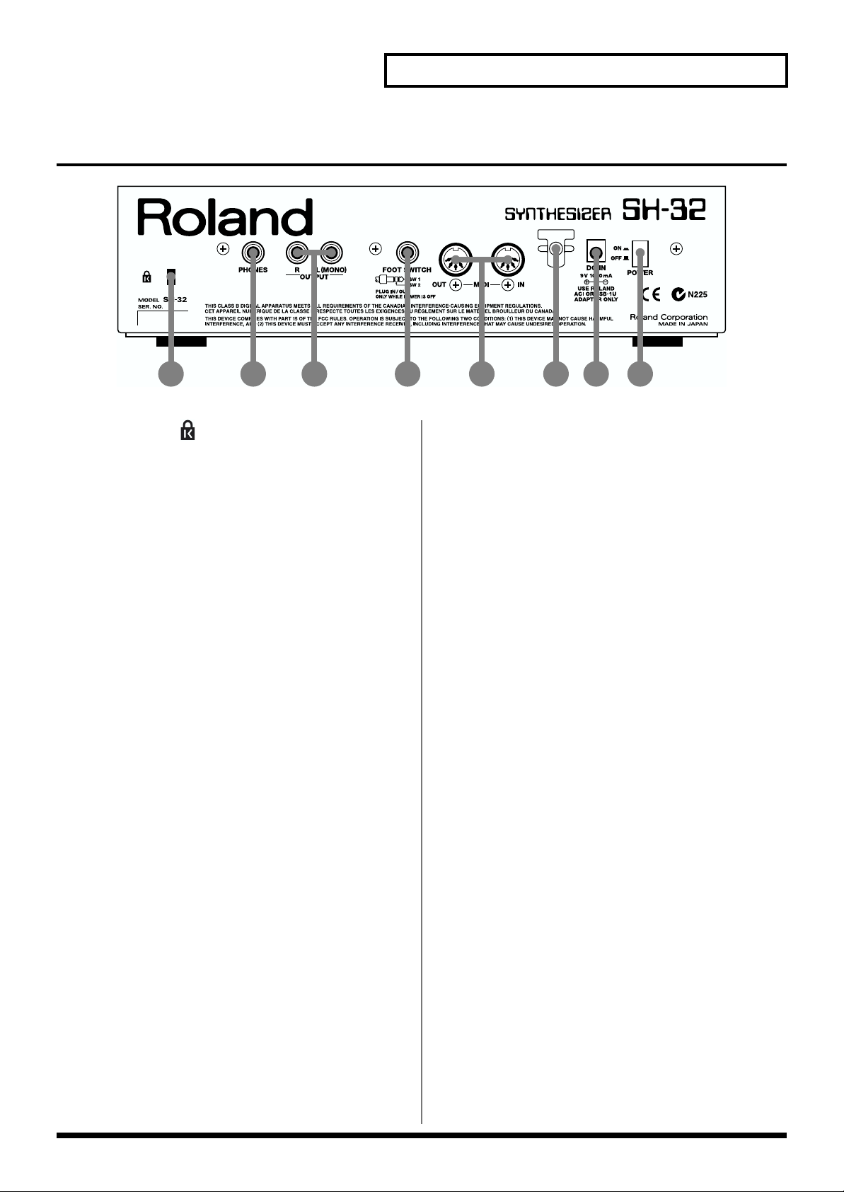
Rear Panel
fig.00-03
Panel Descriptions
1 2 4 6 7 8
3 5
1. Security Slot ( )
http://www.kensington.com/
2. PHONES Jack
This is the jack for connecting headphones (sold separately). → (p.
16)
3. OUTPUT Jacks (L (MONO), R)
These jacks output the audio signal to the connected mixer/amplifier
system in stereo. For mono output, use the L jack. → (p. 16)
4. FOOT SWITCH Jack
You can connect optional foot switch (BOSS FS-5U) or pedal switch
(DP-2) to this jack, you can use it to select or modify sound or
perform various other control. → (p. 16, p. 91)
5. MIDI Connectors (IN, OUT)
These connectors can be connected to other MIDI devices to receive
and transmit MIDI messages. → (p. 16, p. 84, p. 92)
6. Cord Hook
Anchor the supplied AC adaptor cord using the cord hook. → (p. 16)
7. DC IN Jack
Connect the supplied AC adaptor to this jack. → (p. 16)
8. POWER Switch
This turns the power on/off. → (p. 17)
15
Page 16
Getting Ready
Connecting External Devices
The SH-32 does not contain an amp or speakers. In order to produce sound, you need to hook up audio
equipment such as a monitor speaker or a stereo set, or use headphones.
To prevent malfunction and/or damage to speakers or other devices, always turn down the volume, and turn
off the power on all devices before making any connections.
1. Before you make connections, make sure that power is turned off for all devices.
2. Connect supplied AC adaptor to the DC IN jack, and plug the other end into an AC power outlet.
To prevent the inadvertent disruption of power to your unit (should the plug be pulled out accidentally), and
to avoid applying undue stress to the AC adaptor jack, anchor the power cord using the cord hook, as shown
in the illustration.
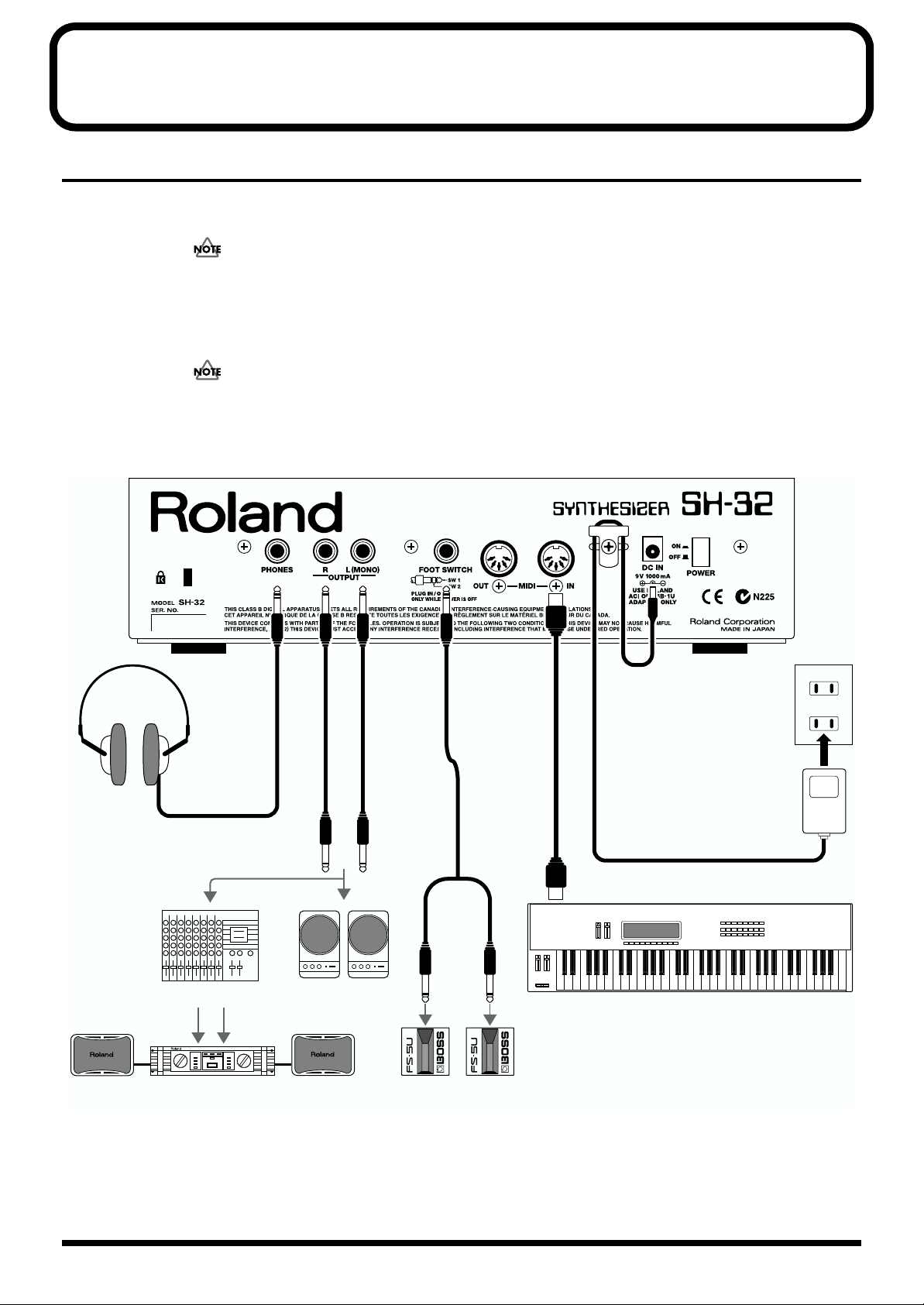
3. Connect the SH-32 and the external device as shown in the figure.
fig.00-04.e
Stereo headphones
AC adaptor
PCS-31
Mixer etc.
Power amp
Use audio cables to connect audio equipment, such as an amp or speakers. Use MIDI cables to connect MIDI
keyboard. If you are using headphones, plug them into the PHONES jack. Connect foot switches or pedal
switches as necessary (p. 91).
Monitor speakers
(powered)
Foot switch (BOSS FS-5U)
or pedal switch (DP-2)
MIDI OUT
MIDI keyboard
16
Page 17
In order to take full advantage of the SH-32’s performance, we
recommend using a stereo amp/speaker system, If you are using
a mono system, make you connections to the OUTPUT jack L
(MONO).
Audio cables, MIDI cables, headphones, foot switches, and pedal
switches are not included. These cables must be acquired
separately.
Getting Ready
Turning Off the Power
1. Before turning off the power, make sure of the following
point.
• Have the volume controls of the SH-32 and all connected audio
devices been turned to the minimum position?
• Have you saved the sounds or other data you’ve created?
2. Turn off the power of the connected audio devices.
3. Turn off the POWER switch of the SH-32.
Turning On the Power
Once the connections have been completed (p. 16), turn on
power to your various devices in the order specified. By turning
on devices in the wrong order, you risk causing malfunction
and/or damage to speakers and other devices.
1. Before you turn the power on, check to make sure that:
• Are peripheral devices connected correctly?
• Have the volume controls of the SH-32 and all connected audio
devices been turned to the minimum position?
2. Turn on the POWER switch located on the rear panel of the
SH-32.
fig.00-05
This unit is equipped with a protection circuit. A brief interval (a
few seconds) after power up is required before the unit will
operate normally.
3. Turn on the power of the connected audio equipment.
4. Play the SH-32 and gradually raise the volume controls of
the SH-32, or the connected audio equipment to an
appropriate volume level.
fig.00-06
Be careful not to raise the volume excessively. Excessive volume
may damage your amp/speaker system or could cause hearing
problems.
Restoring the Factory Settings (Factory Reset)
When using the SH-32 for the first time, start out by restoring the
settings programmed at the factory to ensure that the SH-32
functions correctly according to the procedures described in the
Owner’s Manual.
While you may already have created important data that you
want to keep, all such existing data is lost when Factory Reset
is carried out. If you do have data that you want to keep, save
the data to an external MIDI sequencer or similar device (p. 88).
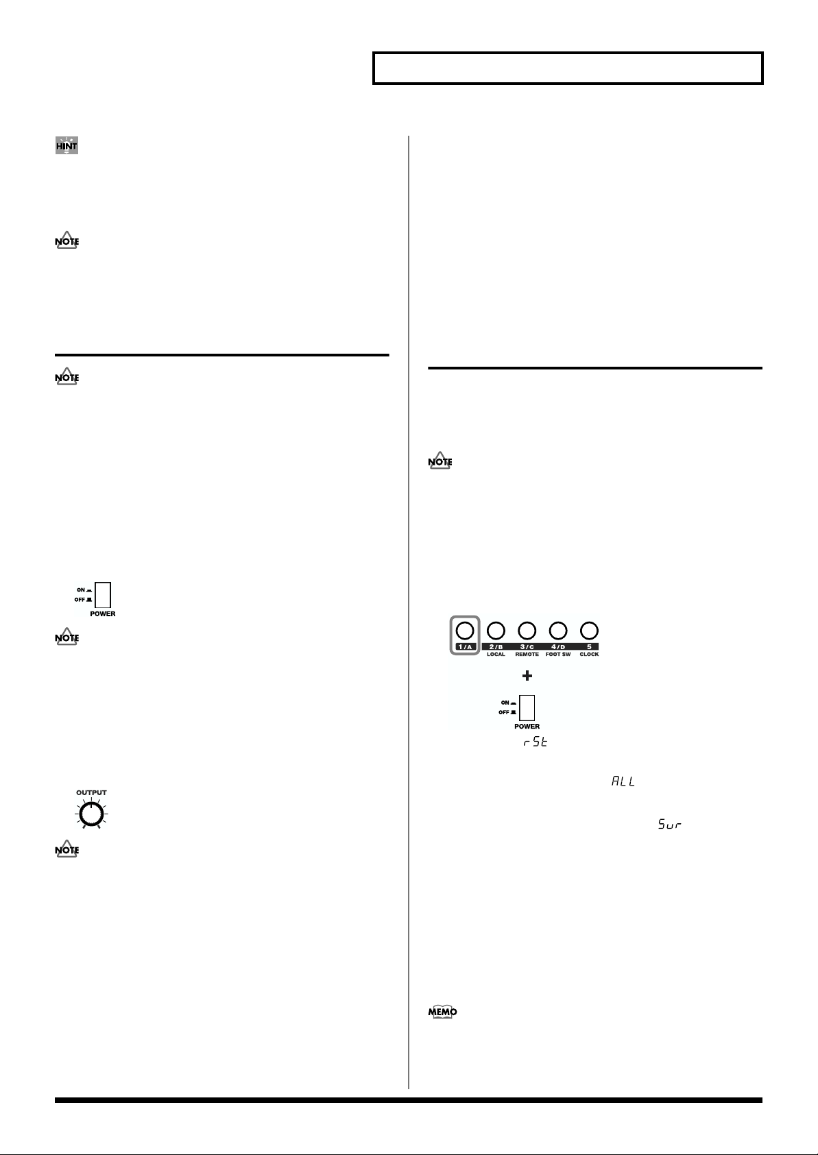
1. First, turn off the power by pressing the POWER switch on
the rear panel.
2. While holding down [1/A], turn the power back on.
fig.00-07
[1/A] blinks; “ ” (Reset) appears in the display as long as
you continue to hold down [1/A].
3. Press [VALUE ▼/▲] to select “ ” (All Data).
4. Press [WRITE (EXEC)].
[WRITE (EXEC)] blinks, and the message “ ” (Sure?) blinks
in the display, prompting you to confirm that you want to carry
out a Factory Reset.
5. Press [WRITE (EXEC)] once more to have the Factory Reset
be carried out. To cancel the Factory Reset, press [EXIT].
All Patches, Rhythm Sets, Performances, Arpeggio Styles,
Rhythm Styles, Chord Forms, and system settings are returned
to the original factory-programmed settings.
6. When you have finished Factory Reset, turn the power off,
then on again.
You can also select the type of data you want to restore to the
original factory settings when carrying out Factory Reset with
the SH-32 (p. 94).
17
Page 18
Getting Ready
Listening to the Demo Songs
The SH-32 comes with three prerecorded demonstration songs.
Playing back these demo songs is called Demo Play. Try starting out
by playing the demo songs, and enjoy listening to the SH-32’s
excellent tones and effects.
No. Song Name Composer Copyright
1 TRAVELER WALL5 2001 © Roland Corporation
2 SPANK SHIBUICHI ABE
(from PCM)
3 CompFusion Ken Suzuki 2001 © Roland Corporation
All rights reserved. Unauthorized use of this material for
purposes other than private, personal enjoyment is a violation of
applicable laws.
2001 © Roland Corporation
Unsaved settings changes may be lost when you start Demo
Play. Carry out the write procedure as required to save such
data before listening to the demo songs (p. 63, p. 70, p. 73).
1. Simultaneously press [LEVEL/PAN] and [EXIT].
This starts Demo Play.
fig.00-08
2. Press [VALUE ▼/▲] if you want to change the song to be
played back.
3. Press [EXIT] to stop Demo Play and return to the normal
operating mode.
• No data for the music that is played will be output from MIDI
OUT.
• The second demo song (spank) is intended to introduce you to
the expanded capabilities provided by the SH-32. Understand
that this demo uses extreme sounds that differ radically from
those used in ordinary demonstration songs.
18
Page 19
Quick Start
Quick Start
19
Page 20
Producing Sound
Getting Started
About the Playing Modes of the SH-32 (PATCH/PERFORMANCE)
SH-32 offers two modes, allowing you to choose the one that is best for the purpose
you have in mind. You can either work with single “Patches” (Patch mode), or use
four Patches (including a Rhythm Set) to play in combination with one another
(Performance mode).
All procedures described in this Quick Start Manual assume that you’re in the Patch
mode, unless stated otherwise. Before operating the SH-32, first be sure that the
Patch mode is selected.
Switching Modes
fig.030
20
1
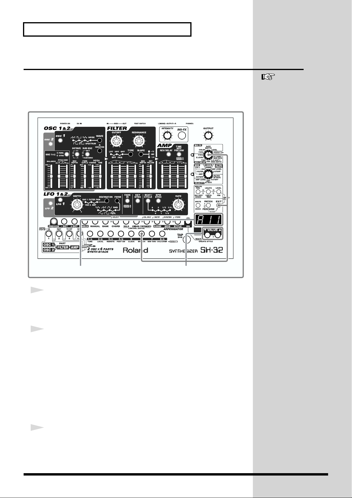
Press [PATCH/PERFORM].
When [PATCH/PERFORM] is not lighted, you are in Patch mode; if it’s lighted,
you’re in Performance mode.
Press the button to toggle between Patch mode and Performance mode.
1
Page 21
Standalone Play of Sounds (PREVIEW)
b
b
b
b
Producing Sound
You can use the note-entry buttons on the unit to play notes (Preview function).
fig.001
12
1
Press [PREVIEW].
[PREVIEW] lights up in red, and the buttons you can use in the preview mode (noteentry buttons) light up in orange.
[OUTPUT]
Quick Start
You can raise or lower the
octave setting by pressing [OCT] or [+OCT] to the right of
[PREVIEW].
Each time you press [-OCT],
the octave goes down. Each
time you press [+OCT], the
octave goes up. You can shift
y up to four octaves in either
direction. You can check the
current octave through the
linking of the button. To
restore the original conditions,
press [-OCT] and [+OCT]
simultaneously.
2
Press any of the note-entry buttons to play a note.
You will hear the note assigned to the button you press.
fig.002
C# D# F# G# A#
C
D E F G A B C
To cancel the Preview function, press [PREVIEW] again to turn off the button.
If you press [HOLD] (lights up
in red), you can have the note
continue to play after you
release the note-entry button
(Hold function). When a note
is played using the Hold
function, the note-entry button
links in amber. To stop the
held note, press the note-entry
utton again.
To cancel the Hold function,
press [HOLD] again to turn off
the button.
How to Change the Volume
Turn [OUTPUT] to change the volume.
By holding down [PREVIEW]
and pressing [VALUE ▼/▲],
you can set the Velocity value
(000–127) for the notes played
with the note-entry buttons.
However, this setting is not
saved.
21
Page 22
Producing Sound
Playing a Sound with a MIDI Keyboard
You can play the SH-32’s sounds using a MIDI keyboard. To do so, you need to
connect the MIDI OUT connector of your keyboard with the MIDI IN connector of
the SH-32 (p. 16).
fig.003
See “Chapter 8. Using the
SH-32 with External MIDI
Devices” (p. 84) for details on
MIDI settings.
Display
1
Set the channel of the MIDI keyboard.
Set the MIDI transmit channel of the keyboard to Channel 1 (refer to the manual that
came with your MIDI keyboard).
2
Set the MIDI channel of the SH-32.
Set the MIDI receive channel to Channel 1.
1. Turn the FX/SYSTEM knob to “SYSTEM.”
2. Press [6 (MIDI CH)].
[6 (MIDI CH)] blinks, and the MIDI channel number appears in the display.
3. Press [VALUE ▼/▲] to select MIDI channel number “1.”
The MIDI receive channel on the SH-32 is set to channel 1.
4. Press [EXIT].
3
Play something on the MIDI keyboard.
The SH-32 sounds the notes that have been played on the MIDI keyboard.
2
22
Page 23
Listening to the Preset Sounds
b
Producing Sound
The SH-32 comes with 128 different Preset Patches, so you can immediately enjoy
having a wealth of sounds at your fingertips.
fig.004
Quick Start
See “Patches (A11–D88)” (p.
45) for detailed information
about the Patches.
“A11” through “B88” are User
Patches, “C11” through “D88”
are Preset Patches. When
shipped from the factory, the
User Patches are the same as
the Preset Patches.
12, 3
1
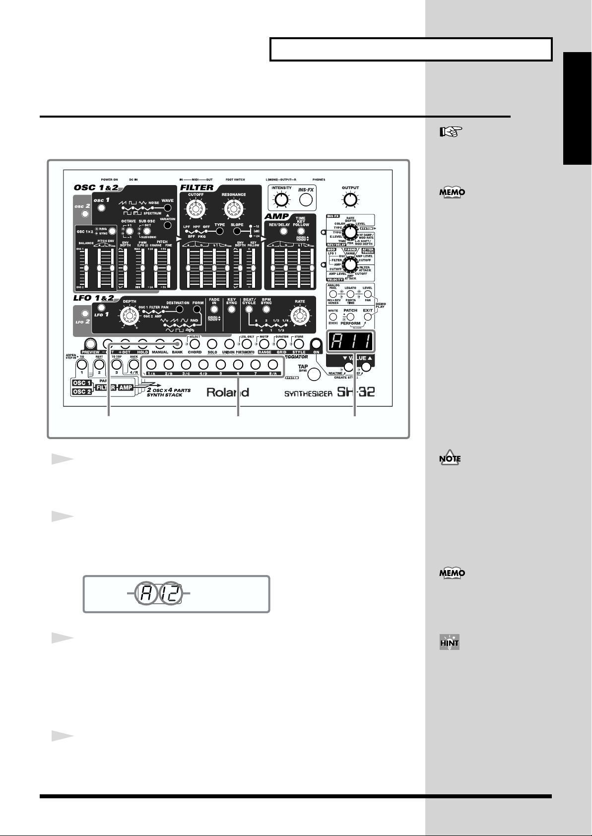
Press [BANK].
[BANK] lights up, and [1/A]–[4/D] and [8/R] blink.
2
Select a bank.
Press [1/A]–[4/D] to select a bank (“A” through “D”).
The selected bank is shown in the display.
fig.005
Bank Patch number
3
Select a Patch number.
Press [1/A]–[8/R] twice to select a Patch number (“11” through “88”). Press the first
button to enter the 2nd digit of the number. Then press another to enter the first digit
of the number.
The selected Patch number is shown in the display.
Display
In step 1, if all of the buttons
from [1/A] through [8/R] are
linking after you press
[BANK], you will need to press
[PATCH/PERFORM] to turn
them off, then press [BANK]
again (Patch mode p. 20).
In step 2, you can select a
Rhythm Set by pressing [8/R]
(p. 25).
When a Patch number is
shown in the display, you can
also press [VALUE ▼/▲] to
select a preset sound.
4
Use the Preview function (p. 21), or a MIDI keyboard to play some
sounds.
The selected sound will be heard.
23
Page 24
Producing Sound
Using the Effects
The SH-32 comes with two independent effects processors; one of them provides
spatial effects such as reverb and delay (Reverb/Delay), while the other is used for
inserting distortion, phaser, tremolo, and various other effects (Insertion Effects).
Effects can be switched on or off at the touch of a button.
fig.006
See “Chapter 3. Applying
Effects to the Sound (INSFX, REV/DELAY)” (p. 64) for
details on effects.
1
1
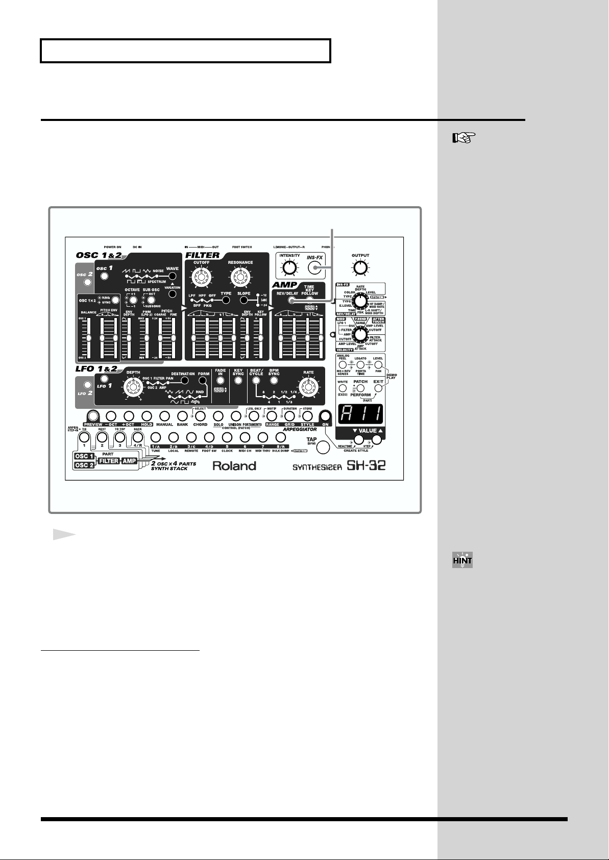
Press [INS-FX] or [REV/DELAY].
When you press [INS-FX], the button lights up, and the Insertion Effects is turned on.
When you press [REV/DELAY], the button lights up, and the Reverb/Delay is
turned on.
The Insertion Effects and Reverb/Delay can be used at the same time.
How to Turn Off the Effects
Press [INS-FX] or [REV/DELAY] to turn them off.
24
You can set the type, intensity,
and other details (p. 34).
Page 25
Playing a Rhythm Set
b
Producing Sound
Apart from general synthesizer sounds, the SH-32 also has four Rhythm Sets. By
using the onboard Arpeggiator (p. 36, p. 74), you can play a loop of simple rhythm
patterns.
fig.007
Quick Start
See “Rhythm Sets (r1U, r2U,
r3P, r4P)” (p. 45) for details on
Rhythm Sets.
13 2
1
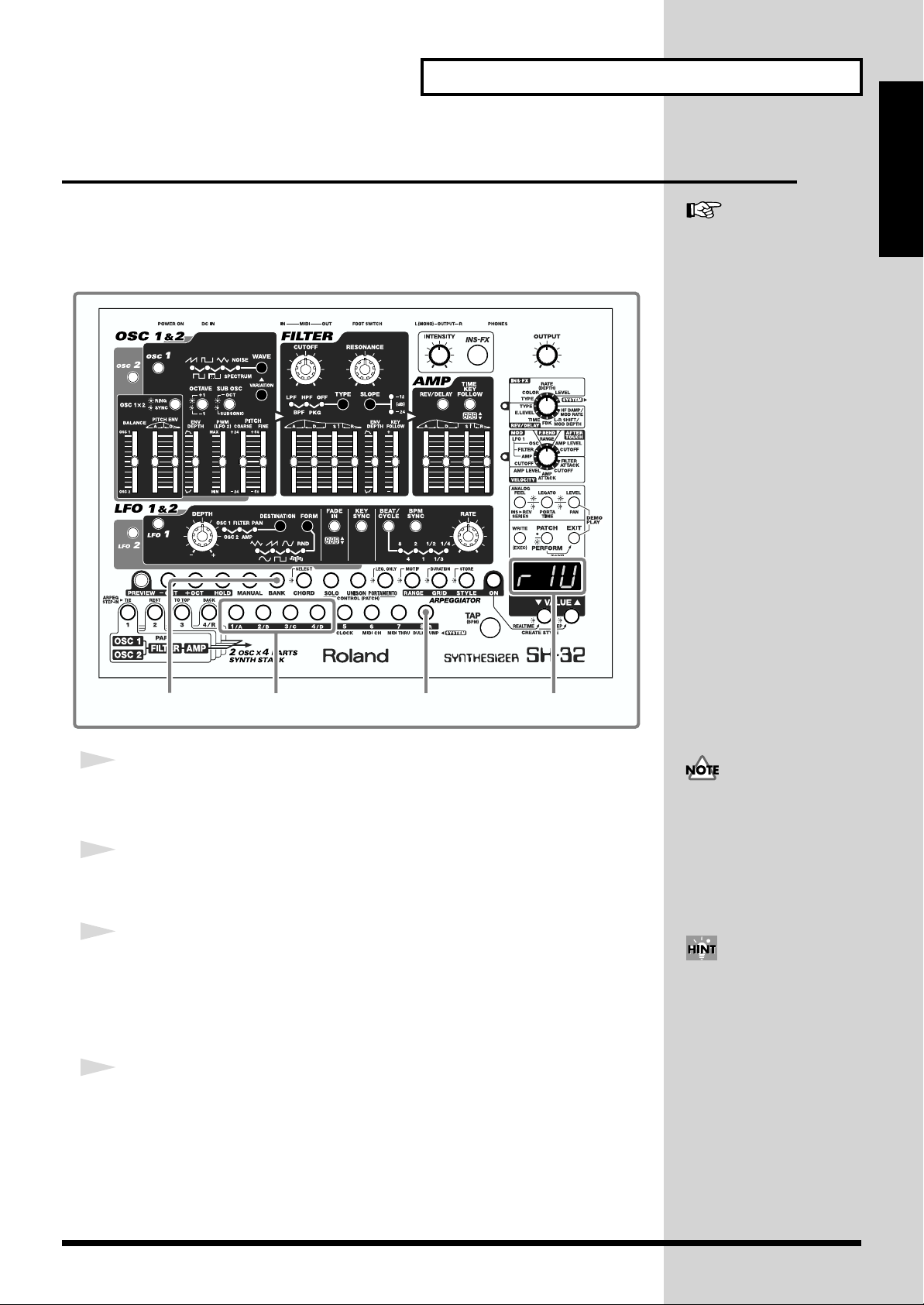
Press [BANK].
[BANK] lights up, and [1/A]–[4/D], [8/R] blink.
2
Press [8/R].
You can select a Rhythm Set.
3
Press [1/A]–[4/D] to select a Rhythm Set number.
The selected Rhythm Set number is shown in the display.
r1U, r2U: User Rhythm Sets (can be overwritten)
r3P, r4P: Preset Rhythm Sets (cannot be overwritten)
4
Use the Preview function (p. 21), or a MIDI keyboard to play some
sounds.
The selected Rhythm Set will be heard.
Display
In step 1, if all of the buttons
from [1/A] through [8/R] are
linking after you press
[BANK], you will need to press
[PATCH/PERFORM] to turn
them off, then press [BANK]
again (Patch mode p. 20).
When a Rhythm Set number is
shown in the display, you can
also press [VALUE ▼/▲] to
select a Rhythm Set.
25
Page 26
Modifying the Sound
Creating Sounds
The SH-32 creates sounds in much the same way as other analog type synthesizers,
as shown below.
fig.008
OSC 1
Filter
Amplifier Effects
See “Chapter 1. An Overview
of the SH-32” (p. 44) for
details of the SH-32’s structure.
Oscillators
OSC 2
MIX
FILTER
LFO 1, 2
AMP
applies effects
LFO
INS-FX
REV/DELAY
Output
OSC (Oscillators)
Generate the basic waveforms used as the sound source by the synthesizer (p. 27).
FILTER
Alters the tone color by cutting or boosting the harmonic content of the waveforms
created by the oscillators (p. 29).
AMP (Amplifier)
Produces changes in the amplitude of the sound, and creates the attack or decay
portions of a sound (p. 31).
LFO (Low Frequency Oscillator)
An extra slow-rate oscillator that controls the oscillators, filter and amp, creating
effects such as vibrato (p. 32).
Effects
Insert or create various effects such as reverb, delay, flanger, etc. (p. 34)
fig.009
26
OSC (Oscillator) FILTER AMP (Amplifier) LFO
Page 27
Easy Sound Editing
Modifying the Sound
In the following, you will learn how to create a sound using the basic functions of the
SH-32.
When creating a sound, play sounds using the Preview function (p. 21), or using a
MIDI keyboard.
To present a generalized view of what you need to do to edit sounds, this Quick Start
Manual introduces the operation while using Preset Patch “D88.” So, before you
begin, be sure to select Preset Patch “D88” (p. 23).
First, you need to select a waveform for the sound source.
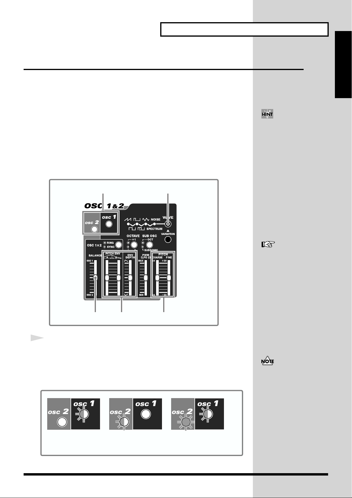
1. Selecting a Waveform (Oscillator)
Here you create the waveforms for the sound source of the synthesizer.
The SH-32 provides 2 oscillators, which can be used independently or mixed.
fig.010
12
Quick Start
When you select a preset
sound (p. 23), the position of
the sliders and knobs may not
always correspond to the
parameters (i.e., the sliders and
knobs do not match the
sound). However, if you press
[MANUAL] (lighting it), the
currently selected parameter
will be set to the values
indicated by the sliders and
knobs. For details, see
“Creating Sounds that
Reflect the Position of
Sliders/Knobs (MANUAL)”
(p. 52).
54 3
1
Press [OSC 1] or [OSC 2] to select the oscillator you want to work
with.
The button you’ve pressed blinks, indicating that it is ready to be manipulated.
When the button is illuminated, it indicates that the oscillator is turned on (when
turned off, the button is extinguished).
fig.012
blinking blinking lit blinking
OSC 2 off / OSC 1 on
You can control
OSC 1 parameters.
OSC 2 on / OSC 1 off
You can control
OSC 2 parameters.
OSC 2 on / OSC 1 on
You can control the parameters of
the OSC whose button is blinking.
See “Determining the Basic
Waveform and Pitch (OSC 1
& 2)” (p. 52) for details on the
oscillator.
The oscillator control panel
controls both OSC 1 and OSC
2. When you select OSC 2 after
setting OSC 1, the values of
settings may not match the
positions of the panel controls.
This happens because, even
after you select the other OSC,
the panel controls remain at
the same positions. Be careful
with the position of controls
when you are operating with
OSC 1 and OSC 2 at different
settings.
27
Page 28
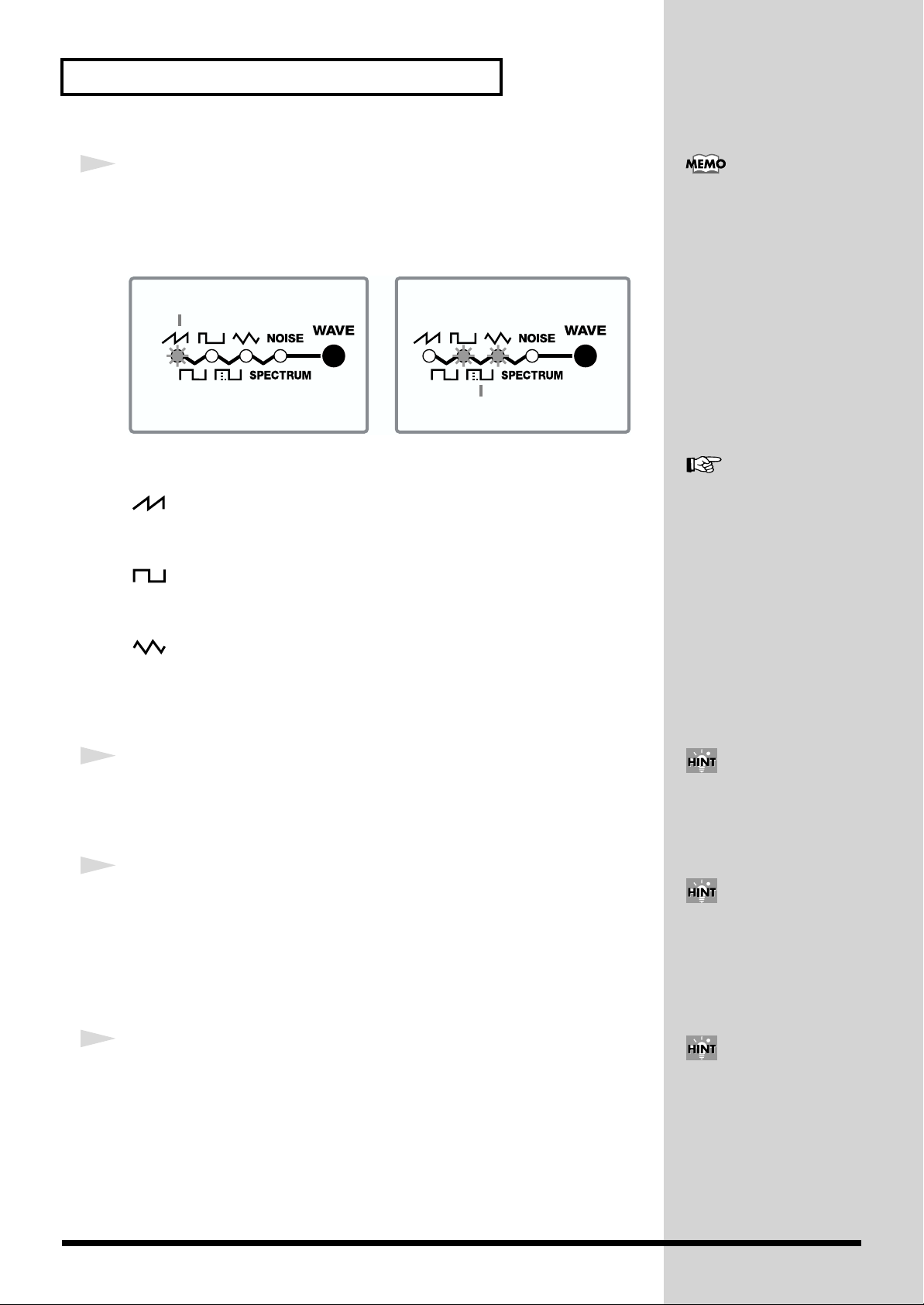
Modifying the Sound
b
2
Press [WAVE] to select a waveform group.
The indicator for the currently selected waveform lights. To select one of the lower
waveforms, get the two indicators above the waveform to light.
fig.011
The selected waveform
Here are some examples of waveform groups.
Saw Tooth waveform group
The waveforms of this group contain a fundamental sine wave and its integral
harmonics, at a fixed ratio. This produces a sharp and bright tone.
Each group of waveforms has
various waveform patterns,
which you can select by
pressing [VARIATION] (p. 53).
The selected waveform
See “Determining the Basic
Waveform and Pitch (OSC 1
& 2)” (p. 52) for details on
waveforms.
Square waveform group
The waveforms of this group contain a fundamental sine wave and its odd
numbered harmonics at a fixed ratio.
Triangle waveform group
This waveform group contains two types of sine waves and does not have any strong
harmonics.
Monitor the sound while you choose the preferred waveform group.
3
Slide [PITCH COARSE] and [PITCH FINE] to set the sound’s pitch.
Slide [PITCH COARSE] to change the pitch extensively. Slide [PITCH FINE] to finetune the pitch.
4
Slide [ENV DEPTH] and [PITCH ENV] to change the pitch over time.
Slide [ENV DEPTH] to adjust the depth of the pitch envelope.
Slide [PITCH ENV/A] to set the time required for the pitch change to reach its
maximum. Slide [PITCH ENV/D] to set the time required for the pitch change to
drop from the maximum to its original state. Both oscillators use [PITCH ENV A/D]
in common.
You can easily shift the octave
up or down by pressing
[OCTAVE] (one octave up or
down) (p. 54).
Using [SUB OSC] (p. 54), you
can also add portions an
octave lower to create a deep
ass sound.
5
Using [BALANCE], adjust the balance between oscillators 1 and 2.
When [OSC 1] or [OSC 2] is illuminated and its counterpart is blinking (when both
are not off), set the balance between the both.
With this, the waveform upon which your sound is to be based is now ready. Next,
we’ll refine the sound by applying a filter to the waveform.
You can also synchronize the
oscillator 1 waveform to the
oscillator 2 pitch (p. 55).
28
Page 29
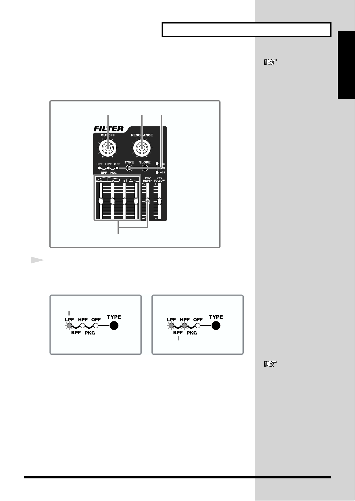
Modifying the Sound
2. Working on Oscillator Waveforms (FILTER)
The filter alters the tone color by cutting or boosting the harmonics of the waveforms
created by the oscillator.
fig.013
213
See “Changing the
Characteristics of Sounds
(FILTER)” (p. 56) for details on
the Filter.
Quick Start
4
1
Press [TYPE] to select a filter type.
The indicator of the selected filter type lights up. To select a filter type on the lower
row, get the two indicators above the name to light.
fig.014
The selected filter
The selected filter
LPF (Low Pass Filter)
Passes lower frequencies and blocks high frequencies. With this filter you can soften
sharp sounds.
BPF (Band Pass Filter)
Passes specific frequencies and blocks other high and low frequencies. With this
filter you can enhance the midrange frequencies of the sound.
HPF (High Pass Filter)
Passes high frequencies and blocks low frequencies. With this filter you can keep the
upper sound portions, while eliminating the lower sound portions.
PKG (Peaking Filter)
Boosts the frequencies near the cutoff frequency. You can create a wah effect by
adding a constant change to the cutoff frequencies with the LFO (p. 32).
See “Internal Filter Types and
Functions (TYPE, SLOPE)”
(p. 56) for details on filter
types.
29
Page 30
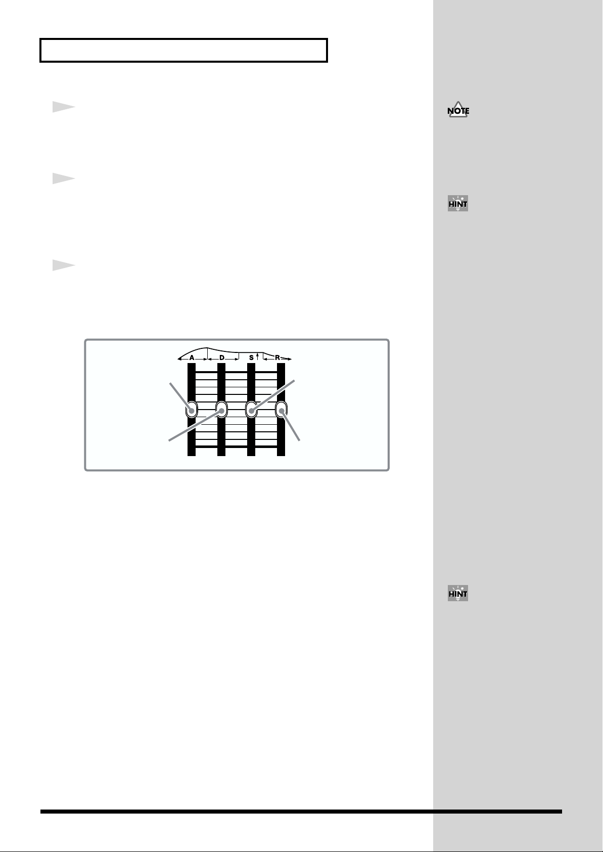
Modifying the Sound
2
Turn [CUTOFF] to set the frequency you want to cut off (Cutoff Point).
Here you determine the Cutoff Point of the filter you selected in step 1. Turn the
knob clockwise to raise the Cutoff Point, and turn it counterclockwise to lower it.
3
Turn [RESONANCE] to enhance the frequency near the Cutoff Point
set in step 2.
The further clockwise you turn the knob, the more the sound takes on a unique
character.
4
To set the filter effect according to time lapse, use the Envelope
sliders and [ENV DEPTH].
Slide [ENV DEPTH] to set the depth of the filter effect (either to + or -), and the
Envelope sliders to set the time characteristics.
fig.015
If you turn [CUTOFF] too
much, all of the audible
frequencies could get
eliminated, and you may hear
no sound.
By operating the [CUTOFF]
and [RESONANCE] knobs you
used in steps 2 and 3 while
playing, you can also create a
special effect.
Attack time slider
Decay time slider
[A]: Attack Time
Sets the time required for the filter’s effect to reach its peak. This time increases as
you raise the slider.
[D]: Decay Time
Determines the time required for the transition from the peak to the sustain level. If
the sustain level is at its maximum, this will have no effect.
[S]: Sustain Level
Determines the level that is to be maintained after the peak has been reached. While
you continue to press a note-entry button (or the key of a MIDI keyboard) it will be
maintained at this level.
[R]: Release Time
Sets the time that is to pass before returning to the original cutoff value, after you
release your finger from a note-entry button (or the key of a MIDI keyboard).
Sustain level slider
Release time slider
You can also change the filter
Cutoff Point by the key range
of the note-entry buttons or
MIDI keyboard (KEY
FOLLOW) (p. 58).
30
Next, let’s make the volume-related settings.
Page 31

3. Adding Changes in the Volume (AMP)
After a sound’s been created by the oscillators and has been filtered, you can apply
changes to the volume of the sound, and control the attack or decay of the sound.
fig.016
1
Modifying the Sound
See “Changing the Volume
(AMP)” (p. 58) for details on
the amp.
Quick Start
1
Use the Envelope sliders to adjust the changes in volume.
fig.015
Attack time slider
Decay time slider
[A]: Attack Time
Sets the time required for the volume to reach its peak. This time increases as you
raise the slider.
[D]: Decay Time
Determines the time required for the volume to drop from the peak to the sustain
level. If the sustain level is at its maximum, this will have no effect.
[S]: Sustain Level
Determines the level at which the volume is to be maintained after the peak has been
reached. While you continue to press a note-entry button (or the key of a MIDI
keyboard) it will keep sounding at this level.
[R]: Release Time
Sets the time needed for the volume to reach zero after you release your finger from
a note-entry button (or the key of a MIDI keyboard).
For example, if you shorten the attack time and lengthen the release time, it may
sound like a piano. If the sustain level is at maximum, it may sound like an organ,
and if the attack time is long, it may sound like a strings section.
Sustain level slider
Release time slider
You can also get the volume
modification times to change
depending on the keyboard
range within which the noteentry buttons or MIDI
keyboard have been played
(TIME KEY FOLLOW) (p. 59).
Now, try modifying the sound using the LFO.
31
Page 32

Modifying the Sound
b
4. Adding Modulation to the Sound (LFO)
The LFO creates waveforms that can control the oscillator, filter, and amp, and add
some extra change to the sound.
The SH-32 has two LFOs. Each LFO can be used independently in setting a different
modulation depth with respect to the oscillator, filter, amp, and pan.
fig.017
23
See “Modulating the Sound
(LFO 1 & 2)” (p. 59) for details
on LFO.
1 4
1
Press [LFO 1] or [LFO 2] to select the LFO you want to control.
The pressed button blinks, indicating that it is available for control.
When the button is illuminated, it indicates that the LFO is turned on (when turned
off, the button is extinguished).
fig.018
blinking lit
LFO 2 off / LFO 1 on
You can control
LFO 1 parameters.
2
Press [FORM] to select a waveform.
The indicator of the selected waveform lights up. To select a waveform on the lower
row, get the two indicators above the waveform to light.
fig.020
blinking blinking
LFO 2 on / LFO 1 off
You can control
LFO 2 parameters.
LFO 2 on / LFO 1 on
You can control the parameters of
the LFO whose button is blinking.
5
The LFO control panel controls
oth LFO 1 and LFO 2. When
you select LFO 2 after setting
LFO 1, the values of settings
may not match the positions of
the panel controls. This
happens because, even after
you select the other LFO, the
panel controls remain at the
same positions. Be careful with
the position of controls when
you are operating with LFO 1
and LFO 2 at different settings.
See “Turning the LFO On and
Off, and Switching
Waveforms (LFO 1, LFO 2,
FORM)” (p. 59) for details on
waveforms.
The selected waveform
The selected waveform
The manner in which sound changes depends on the waveform.
32
Page 33

3
Press [DESTINATION] to set the destination for which the modulation
depth is to be set by means of [DEPTH].
The indicator of the selected destination lights up. To select a destination on the
lower row, get the two indicators above the name to light.
fig.019
The destination
The destination
The manner in which sound changes depends on the destination of the LFO.
OSC 1,2
Adds an effect to the pitch of the waveform, creating a vibrato effect.
FILTER
Adds an effect to the Cutoff Point of the filter, creating a wah effect.
AMP
Adds an effect to the amp, creating a tremolo effect.
PAN
Applies an effect to the left/right positioning of sound, creating an auto-pan effect.
Modifying the Sound
Quick Start
See “Adjusting the
Modulation Depth
(DESTINATION, DEPTH)” (p.
60) for details on the effects.
You can add one LFO effect to
several destinations.
4
Turn [DEPTH] to set the depth of the LFO effect.
The effect increases as you turn the knob clockwise.
5
Turn [RATE] to adjust the frequency (speed) of the LFO.
The speed becomes faster as you turn the knob clockwise, and slower when you turn
it counterclockwise.
You can also synchronize the
LFO with the tempo (BPM) (p.
61).
33
Page 34

Modifying the Sound
5. Adding an Effect
You can add effects to the sound created so far. The SH-32 has two independent
effects processors; one of them provides spatial effects such as reverb and delay
(Reverb/Delay), while the other is used for inserting distortion, phaser, tremolo, and
other various effects (Insertion Effects).
fig.031
See “Chapter 3. Applying
Effects to the Sound (INSFX, REV/DELAY)” (p. 64) for
details on effects.
1
Display
1
Press [INS-FX] or [REV/DELAY].
When you press [INS-FX], the button lights up, and the Insertion Effects is turned on.
When you press [REV/DELAY], the button lights up, and the Reverb/Delay
processor is turned on.
2
Select an effect type and set the rate.
To set the Insertion Effects, turn [INTENSITY] to adjust the intensity, and use the
FX/SYSTEM knob and [VALUE ▼/▲] to set the type and other details.
To set the Reverb/Delay, use the FX/SYSTEM knob and [VALUE ▼/▲] to set the
value.
The effect types and values are shown in the display. See “Chapter 3. Applying
Effects to the Sound (INS-FX, REV/DELAY)” (p. 64) for details.
Are you satisfied with the sound you created?
The sound settings created so far will be lost when you switch off the SH-32. Let’s
now save the sound into the internal memory.
2
You can use the Insertion
Effects and Reverb/Delay at
the same time. You can also
line them up in series or in
parallel (p. 64).
34
Page 35

Saving the Sound
Modifying the Sound
Sound created on the SH-32 relies on a unique interaction of several parameters, so
it’s a good idea to save your sound settings whenever you achieve something you
like, and may want to use later. You can save as many as 128 different sound settings
on the SH-32.
fig.021
Quick Start
Display
1
When you’ve reached the point where you have a sound you want to
save, press [WRITE].
[WRITE] lights up, and a Patch number blinks in the display.
2
Press [VALUE ▼/▲] to select the place where you want to save your
Patch ([A11]–[B88]).
3
Press [WRITE].
The “ ” (Sure?) confirmation message appears in the display. To cancel the save,
press [EXIT].
4
Press [WRITE] again.
First, “ ” (Ok) blinks in the display, then the display returns to its original state.
The sound is now saved to the selected Patch number.
21, 3, 4
You can also select a Patch
number by pressing [BANK],
selecting a bank with [1/A] or
[2/B], and then selecting the
save destination with [1/A]–
[8/R].
35
Page 36

Playing Arpeggio (Arpeggiator)
The SH-32 provides an automatic arpeggio function (Arpeggiator). With this
function, you can play a chord in arpeggio. Also, when a Rhythm Set is selected, you
can play a rhythm pattern.
An arpeggio is played in accord with the keys that are pressed. There are a number
of preset Arpeggio Styles from which you can choose (Arpeggio Styles).
Turning On/Off the Arpeggiator
Let’s play with the Arpeggiator.
fig.024
See “Chapter 6. Using
Arpeggiator
(ARPEGGIATOR)” (p. 74) for
details on Arpeggiator.
21
1
Press [ON].
The button lights up, and the Arpeggiator is turned on.
2
Press [STYLE] to light up the button, and press [VALUE ▼/▲] to select
an Arpeggio Style.
The Arpeggio Style number is shown in the display (“11.a” through “88.a”).
When a Rhythm Set is selected, you can select a Rhythm Style (“11.r” through
“88.r”).
Display
If you press [STYLE] again
while the button is
illuminated, it blinks,
indicating that it is now in
style-save mode (p. 79). When
you press it again, it will
return to style-selection mode.
See “About Arpeggio Styles”
(p. 75) for details on Arpeggio
Styles.
36
Page 37

3
Press a chord by using the Preview function (p. 21) or a MIDI keyboard
to start playing arpeggio.
The Arpeggio Style of the SH-32 starts playing arpeggio according to the position of
the touched key.
fig.023
Example
Playing Arpeggio (Arpeggiator)
You can also create new
Arpeggio Styles (p. 77).
Quick Start
When you select
this style,
When you select a Rhythm Set in Patch mode (p. 25), the selected Rhythm Style will
be played regardless of the position of the touched key.
and play this cord,
How to Turn Off the Arpeggiator
Press [ON] to turn the button off.
you will hear this.
37
Page 38

Playing Arpeggio (Arpeggiator)
Changing the Arpeggiator Tempo
You can change the tempo for arpeggio performances.
fig.025
3
1
Press [TAP (BPM)].
[TAP (BPM)] lights up.
2
Press [VALUE ▼/▲] to set the desired tempo.
The tempo is shown in the display.
3
Press [EXIT] to turn the button off.
21
Display
You can also set the tempo to
the timing you’ve used when
tapping the buttons (Tap
Tempo) (p. 74).
38
Page 39

Playing Arpeggio (Arpeggiator)
Playing the Arpeggio Together with a Rhythm Pattern
In Performance mode, you can play the arpeggio while playing a rhythm pattern.
fig.026
Quick Start
2, 4, 7, 9, 111, 2, 96, 13
3, 68, 13 3, 10 5, 12
1
Press [PATCH/PERFORM] to light up the button, and to enter
Performance mode.
In Performance mode, you can play four Parts (each with its own Patch assigned to
it) at the same time.
2
Press [EXIT] while pressing [PATCH/PERFORM], getting both buttons
to blink.
The unit is now in the Part Assign mode.
3
Set the Rhythm Set to Part 4.
1. Press [4/R].
[4/R] blinks.
2. Press [BANK], and then press [8/R].
3. Press [1/A]–[4/D] to select a Rhythm Set number.
The Rhythm Set number is shown in the display.
The Rhythm Set can only be set to Part 4.
Display
See “Chapter 5. Using in
Performance Mode” (p. 71)
for details on Performance
mode.
See “Selecting the Patch for
Each Part (Part Assign
Mode)” (p. 71) for details on
the Part Assign mode.
39
Page 40

Playing Arpeggio (Arpeggiator)
4
Press [EXIT] to return to Performance mode.
5
Press [STYLE] to light up the button and then press [VALUE ▼/▲] to
select a Rhythm Style.
The Rhythm Style number is shown in the display.
6
Press [4/R] while pressing [ON] to light up [4/R].
The Part 4 is set for the arpeggio play.
7
Press [EXIT].
8
Press [1]–[3] to choose a Part you want to play in arpeggio.
The button of the selected Part blinks.
See “About Rhythm Styles”
(p. 75) for details on Rhythm
Styles.
9
Press [EXIT] while pressing [PATCH/PERFORM], getting both buttons
to blink.
The unit is in the Part Assign mode.
10
Select a Patch for the Part you selected in step 8.
1. Press [BANK], and then press [1/A]–[4/D].
2. Press [1/A]–8/R] to select a Patch number.
The Patch number is shown in the display.
11
Press [EXIT] to return to Performance mode.
12
Press [STYLE] to light up the button, and then press [VALUE ▼/▲] to
select an Arpeggio Style.
The Arpeggio Style number is shown in the display.
13
Press the Part button that was selected in Step 8 while pressing [ON]
to light up the Part button.
The selected Part is set for arpeggio play.
See “Selecting the Patch for
Each Part (Part Assign
Mode)” (p. 71) for details on
the Part Assign mode.
See “About Arpeggio Styles”
(p. 75) for details on Arpeggio
Styles.
40
14
Use the Preview function (p. 21), or a MIDI keyboard to play some
sounds.
The rhythm pattern and arpeggio start playing.
Page 41

Playing a Chord at the Touch of a Finger (Chord Memory)
You can easily play a chord simply by touching just one key to which a “Chord
See
Form” has been registered (Chord Memory function). The SH-32 can remember 64
different Chord Forms (11.c–88.c)
Using the Chord Memory Function
Here’s how you can play a chord by using the Chord Memory function.
fig.027
“Chapter 7. Using the
Chord Memory Function
(CHORD)”
the Chord Memory function.
The Chord Memory function
cannot be used with Rhythm
Sets.
(p. 81) for details on
Quick Start
1
1
Press [CHORD] to light up the button.
The Chord Memory function is turned on.
2
Use the Preview function (p. 21), or a MIDI keyboard to play a single
note.
You will hear a chord that corresponds to the Chord Form you’ve selected (p. 42).
When you press the C4 key, you will hear the actual chord that is stored in the Chord
Form. The other keys produce chords in a parallel manner relative to the C4 key.
How to Turn Off the Chord Memory Function
Press [CHORD] twice to turn off the button, and the Chord Memory function is
turned off.
You can also use a foot switch
to turn on/off the Chord
Memory function (p. 91).
41
Page 42

Playing a Chord at the Touch of a Finger (Chord Memory)
Switching Chord Forms
You can select the Chord Form that has the chord you want to play from the preset
Chord Forms.
fig.028
See “Selecting Chord Forms”
(p. 81) for more information
about Chord Forms.
1 2
1
Press [CHORD] to make it blink.
2
Press [VALUE ▼/▲] to select a Chord Form number (11.c–88.c).
The Chord Form number appears in the display.
3
Use the Preview function (p. 21), or a MIDI keyboard to play sounds.
Display
You can also change the Chord
Form by pressing [BANK] and
[1/A]–[8/R]. In this case, you
will hear the C4 sound for
confirmation.
You can also use a foot switch
to change the Chord Form (p.
91).
Not only can you use the
Chord Forms that come preprogrammed from the factory,
you can also freely create and
rewrite your own original
Chord Forms as well. For more
detailed instructions on
creating Chord Forms, refer to
“Creating Your Own Chord
Forms” (p. 82).
42
Page 43

Advanced Use
Chapter 1Chapter 2Chapter 3Chapter 4Chapter 5Chapter 6Chapter 7Chapter 8Chapter 9
43
Page 44

Chapter 1. An Overview of the SH-32
How the SH-32 is Organized Internally
The SH-32 is broadly organized as follows.
fig.01-01.e
Local Switch
SH-32
Controller Arpeggiator
Preview Switch
Preview Function
Sound
Generator
MIDI Thru
Switch
OFF
ON
Remote
Switch
MIDI OUT MIDI IN
MIDI OUT
MIDI Keyboard
MIDI Connectors
The SH-32 is equipped with two MIDI connectors (IN, OUT).
When the Remote Keyboard switch (REMOTE; p. 90) is set to ON,
actions performed on an external MIDI keyboard connected to the MIDI
IN connector are treated in the same way as those performed using the
SH-32’s Preview function (p. 21) to play sounds. You can also choose to
have the OUT connector function as a THRU connector (p. 92).
Sound Generator
This is the section that produces the sound. You can play sounds
using note messages from an external MIDI device. In addition,
when the Preview function is turned on, you can play sounds by
pressing designated button (note-entry buttons) on the SH-32 (p. 21).
About Maximum Simultaneous Notes
The SH-32 is capable of using 32 oscillators simultaneously. Data for
greater numbers results in sounds being omitted. When all 32
oscillators are being used, any further sounds are given priority,
deleting the sounds currently being played one at a time, starting
with the least recent sound and progressing in order as more sounds
are added. Keep this in mind when playing sounds with a lot of
reverb, or when using the Chord Memory function.
(Note, though, that turning on the Suboscillator function does not
impact the oscillator count.)
Arpeggiator
Arpeggios can be played in accord with note messages from an
external MIDI device.
In addition, Using the Preview function, you can also control the
Arpeggiator by pressing the designated buttons (note-entry buttons)
(p. 21).
Controller
Controllers are the sliders, knobs, and buttons arranged on the
panel. By operating these controllers, you can modify sounds.
Naturally, you can use an external MIDI controller (such as a
keyboard, pitch bend lever, or modulation lever) to make changes in
the sounds.
44
Page 45

Chapter 1. An Overview of the SH-32
Patches, Rhythm Sets, and Performances
Patches (A11–D88)
An individual sound used in a performance is called a Patch. The
SH-32 offers a total of 256 Patches, divided into 128 “User Patches”
and 128 “Preset Patches.”
fig.01-02.e
Patch
OSC
PITCH
Envelope
audio signal
Patches consist of the following five components.
OSC (Oscillator)
Provides for selection of the waveforms (waves) that form the basis
for sounds, and sets the pitch. There are two oscillators (OSC 1 and
OSC 2), and you can combine these to create a wide variety of
different sounds.
You can only make pitch-related settings for the Rhythm Tones
(percussion instruments) in the OSC section.
FILTER
Changes the brightness and other qualities of the sound, by setting
the characteristics of the constituent frequencies.
LFO 1 LFO 2
FILTER
FILTER
Envelope
control signal
AMP
AMP
Envelope
LFO (Low Frequency Oscillator)
Use the LFO to create cyclic changes (modulation) in a sound. There
are two LFOs (LFO 1 and LFO 2), and the effects of each one are
applied to OSC (pitch), FILTER (filter), and AMP (volume or pan).
When an LFO is applied to the OSC pitch, a vibrato effect is
produced. When an LFO is applied to the FILTER cutoff frequency, a
wah effect is produced. When an LFO is applied to the AMP volume,
a tremolo effect is produced.
You cannot apply LFO effects to the Rhythm Tones (percussion
instruments).
Rhythm Sets (r1U, r2U, r3P, r4P)
A collection of multiple percussion instrument sounds is called a
Rhythm Set. The SH-32 comes with four Rhythm Sets, divided into
two “User Rhythm Sets” and two “Preset Rhythm Sets.”
Since percussion instruments generally do not play melodies, there
is no need for a percussion instrument sound to be able to play a
scale on the keyboard. It is, however, more important that as many
percussion instruments as possible be available to you at the same
time. Therefore, each key (note number) of a Rhythm Set will
produce a different percussion instrument.
fig.01-03.e
Rhythm Set
Note number 98 (D7)
Note number 97 (C#7)
Note number 36 (C2)
Note number 35 (B1)
Rhythm tone (Percussion instrument sound)
OSC
PITCH
Envelope
Each percussion instrument consists of the following four elements.
(For details, refer to the explanations for “Patches.”)
FILTER
FILTER
Envelope
AMP
AMP
Envelope
Chapter 1
AMP (Amplifier)
Sets the changes in volume.
Envelope
You use Envelope to initiate changes to occur to a sound over time.
There are separate envelopes for Pitch, FILTER (filter), and AMP
(volume). For example if you wish to modify the way in which the
sound attacks or decays over time, you would adjust the AMP
envelope.
OSC (Oscillator)
FILTER
AMP (Amplifier)
Envelope
45
Page 46

Chapter 1. An Overview of the SH-32
Performances (1-1–8-8)
A combination of four Patches, or of three Patches and a Rhythm Set,
is called a Performance. The SH-32 contains 64 Performances; all of
these are User Performances that can be overwritten at will.
With Performances, four separate tones are handled simultaneously,
thus allowing you to enjoy playing ensemble performances or
performances using lush tones.
fig.01-04.e
Performance
Part 4/R
Patch/
Rhythm Set
Part 3
Part 2
Part 1
Patch
Part
A Part is the place to which a Patch or Rhythm Set is assigned when
using the SH-32 in Performance mode. A single Performance
comprises four Parts, with a Patch being assigned to each Part. You
can also assign a Rhythm Set to only Part 4.
How Characters and Numerals Are Displayed
The display of the SH-32 indicates characters and numbers as
follows.
fig.01-04a.e
A
B C D E F G H I J K L M N
Capital
letters
Small
letters
O P Q R S T U V W X Y Z
Capital
letters
Small
letters
1 2 3 4 5 6 7 8 9 0
• Since Performances store only information such as the Patch
numbers used by individual Parts, they do not contain any
actual sound parameter settings. Accordingly, if you modify any
content saved to a Patch, it affects the sound of every
Performance in which that Patch is used.
• Other than switching them on and off and adjusting the levels,
no settings are made for the two effects processors (INS-FX,
REV/DELAY) in the Performance itself. INS-FX (Insertion
Effects) and REV/DELAY (Reverb/Delay) are each specified in
Parts (p. 66), and the effect settings in the Patches assigned to
those Parts are treated as the effect settings for the Performance
as a whole.
The Different Data Saved Separately to
Patches and Performances
● Arpeggio Styles/Rhythm Styles
These contain the arpeggios’ basic styles; they are used by the
Arpeggiator. 64 of each kind are provided, all of which can be
overwritten by the user (p. 79).
● Chord Forms
These contain combinations of note numbers, which are used
with the Chord Memory function. The unit provides 64 Forms,
all of which can be overwritten by the user (p. 83).
46
Page 47

Chapter 1. An Overview of the SH-32
About Memory
Patch and Performance settings are stored in what is referred to as
memory. There are three kind of memory: temporary, rewritable,
and non-rewritable.
fig.01-05.e
SH-32
System
Preset
Patch
128
Rhythm Set
2
Select Select
Rhythm Set
Performance
Temporary Area
Temporary Memory
Patch
128
2
64
User
Arpeggio Style
Rhythm Style
Chord Form
64
64
64
Write
Rewritable Memory
System Memory
System memory stores system parameter settings that determine
how the SH-32 functions.
User Memory
User memory is where you normally store the data you need. User
memory contains 128 patches, 2 rhythm sets, 64 performances, 64
arpeggio styles, 64 rhythm styles, and 64 chord forms.
Arpeggio Styles, Rhythm Styles, and Chord Forms are saved as
separate settings, independent of Patches and Performances.
When these are overwritten or changed, it affects how sounds of
Patches (including the Preset Patches) and Performances that use
the Arpeggiator and Chord Memory functions are played.
Non-Rewritable Memory
Preset Memory
The contents of preset memory cannot be rewritten. However, you
can call up settings from preset memory into the temporary area,
modify them and then store the modified data in rewritable
memory.
Chapter 1
Temporary Area
This is the area that holds the data for the Patch, Rhythm Set, or
Performance that you’ve selected using the panel buttons.
When you play the keyboard or play back a sequence, sound is
produced based on data in the temporary area. When you edit a
Patch, Rhythm Set, or Performance, you do not directly modify the
data in memory; rather, you call up the data into the temporary area,
and edit it there.
Settings in the temporary area are temporary, and will be lost when
the power is turned off or when you select another Patch/Rhythm
Set/Performance. To keep the settings you have modified, you must
write them into rewritable memory.
Separate “Patch temporary areas” are maintained independently
for the Patch mode and Performance mode. If you have switched
between these two modes during the process of editing one and
the same Patch, and then you save your changes while in one of
these modes, the content of the temporary area for the other
mode will not be revised.
47
Page 48

Chapter 1. An Overview of the SH-32
Main Setting Destinations
■ Patches and Performances
fig.01-06.e
Patch
STYLE No. (A)
Basic T ones
OSC1/OSC2
LFO1/LFO2
PATCH LEVEL
PATCH PAN
Arpeggiator Settings
BPM
ON/OFF
FILTER
AMP
Arpeggio Style
Rhythm Style
Effective only in
Patch mode
GRID TYPE
DURATION
RANGE
MOTIF
Control
SOLO
UNISON
PORTAMENTO
LEGATO
ANALOG FEEL
Chord Memory
ON/OFF
CHORD No.
Effects
ON/OFF(INS)
ON/OFF(REV)
SERIES SW
MIDI
P.BEND
AFTER TOUCH
MOD
VELOCITY
Effective in both modes
(In Performance mode,
only settings for the
Part specified as the
reference are enabled)
INS-FX detailed parameters
(COLOR, DEPTH ...)
REV/DELAY detailed
parameters (TIME, FBK, ...)
Used in both modes
(in Performance
mode, enabled for
each separate Part)
Chord
PERFORMANCE LEVEL
MIDI CH
PART TUNE
PART LEVEL
PART PAN
OSC RESERVE
Arpeggiator Settings
STYLE No. (R)
STYLE No. (A)
BPM
ON/OFF
Part Stack
Edits Patch
and Rhythm
Set settings
Patch No.
Dest. Part
GRID TYPE
DURATION
RANGE
MOTIF
Performance
Effects
REV/DELAY
Send Level
Effects
ON/OFF(INS)
ON/OFF(REV)
SERIES SW
Chord
Memory
Effective only in
Performance mode
ON/OFF(INS)
ON/OFF(REV)
PART 1
INS-FX Setting
Source Part
REV/DELAY Setting
Source Part
Dest. Part CHORD No.
2
3
4
48
Page 49

fig.01-07.e
Chapter 1. An Overview of the SH-32
■ Rhythm Sets and Performances
Rhythm Set
RHYTHM SET LEVEL
Arpeggiator Settings
STYLE No. (R) GRID TYPE
ON/OFF
INST LEVEL INST PAN
Basic T ones
PITCH
FILTER
AMP
Rhythm Style
VELOCITY
Effective only in
Patch mode
BPM
MIDI
P.BEND
Effects
ON/OFF(INS)
ON/OFF(REV)
SERIES SW
REV/DELAY
Send Level
ON/OFF(INS)
ON/OFF(REV)
Effective in both modes
(in Performance mode,
only used when a
Rhythm Part is
specified as the
referred source)
INS-FX detail
(COLOR, DEPTH ...)
REV/DELAY detail
(TIME, FBK, ...)
Used in both modes
(each key; different
settings can be made
for each percussion
instrument)
Chapter 1
PERFORMANCE LEVEL
PART PITCH
PART LEVEL
PART PAN
OSC RESERVE
PART 4/R
3
2
1
Arpeggiator Settings
STYLE No. (R)
BPM
ON/OFF
GRID TYPE
Performance
MIDI CH
Edits Rhythm
Set settings
Rhythm Set No.
Effects
ON/OFF(INS)
ON/OFF(REV)
SERIES SW
Effects
REV/DELAY
Send Level
REV/DELAY Setting
Effective only in
Performance mode
ON/OFF(INS)
ON/OFF(REV)
INS-FX Setting
Source Part
Source Part
49
Page 50

Chapter 1. An Overview of the SH-32
Objects of Settings That Change with the SH-32’s Mode
Even when the same knobs and buttons are used, the parameters that are changed with various settings vary
according to the current mode as shown by the table on the following page.
50
Page 51

Chapter 1. An Overview of the SH-32
Patch Mode Performance Mode Part Assign Mode Rhythm Tone Edit
Preview function
turned on with a
Rhythm Set selected
in each mode
• You can switch the Insertion Effects
(INS-FX) or Reverb/Delay (REV/
DELAY) on (indicator lit), or off (indicator off) for each individual
Patch or Rhythm Set (p. 64, p. 65).
• You can save settings content to
each Patch or Rhythm Set with the
write procedure (p. 63, p. 70).
* When assigning Patches to the Parts
in Performance mode, the settings
here are disabled, and the settings
for each Part in Part Assign mode
go into effect.
• Makes the detailed Insertion Effects
(INS-FX) or Reverb/Delay (REV/
DELAY) settings for each Patch or
Rhythm Set (p. 65, p. 66).
• Turn the knob to the desired parameter (other than SYSTEM), then
press [VALUE ▼/▲] to make the
settings.
• You can save settings content to
each Patch or Rhythm Set with the
write procedure (p. 63, p. 70).
• Sets the volume (LEVEL) or panning (PAN) for each individual
Patch or Rhythm Set (p. 59, p. 63).
• Press the button: if the indicator is
lit, the volume is set; the pan is set
when the indicator is blinking. Press
[VALUE ▼/▲] to set the values.
• You can save settings content to
each Patch or Rhythm Set with the
write procedure (p. 63, p. 70).
* When assigning Patches to the Parts
in Performance mode, both the settings here as well as the settings for
each Part made in Part Assign mode
are enabled.
• Sets whether Insertion Effects (INSFX) and Reverb/Delay (REV/DELAY) for each Patch or Rhythm Set
are to be connected in series (SEr),
or in parallel (PAr) (p. 64).
• Press the button, causing the indicator to blink, then press [VALUE ▼/
▲] to make the settings.
• You can save settings content to
each Patch or Rhythm Set with the
write procedure (p. 63, p. 70).
* When assigning Patches to the Parts
in Performance mode, the settings
here are disabled, and the Performance settings go into effect.
• You can also change Patch tones using controls other than the sliders
and knobs mentioned above.
• You can switch the Insertion Effects
(INS-FX) or Reverb/Delay (REV/
DELAY) on (indicator lit), or off (indicator off) for each individual Performance (p. 64, p. 65).
• You can save settings content to
each Performance with the write
procedure (p. 73).
• Sets the parameters of the Patch or
Rhythm Set assigned to the Part
specified as the Performance’s effect
source (p. 65, p. 66).
• The procedure for making the settings is the same as in Patch mode.
• You can save settings content to
each Patch or Rhythm Set with the
write procedure (p. 73).
* Effect parameter settings are not
saved to the Performances.
• Sets the volume (LEVEL) setting for
each individual Performance (p.
59). The panning (PAN) cannot be
set.
• The procedure for making the settings is the same as in Patch mode.
• You can save settings content to
each Performance with the write
procedure (p. 73).
* The pan settings for Performances
are saved to each Part in Part Assign
mode.
• Sets whether Insertion Effects (INSFX) and Reverb/Delay (REV/DELAY) for each Performance are to be
connected in series (SEr), or in parallel (PAr) (p. 64).
• The procedure for making the settings is the same as in Patch mode.
• You can save settings content to
each Performance with the write
procedure (p. 73).
* When assigning Patches to the Parts
in Performance mode, the Patch settings are disabled, and the settings
made here go into effect.
• You can use controls other than the
sliders and knobs mentioned above
to change tone settings in Patches
assigned to each Part in Performance mode.
• You can switch the Insertion Effects
(INS-FX) or Reverb/Delay (REV/
DELAY) on (indicator lit), or off (indicator off) for each individual Part
in a Performance (p. 64, p. 65).
• Press [1]–[4/R] (Part buttons) to
specify the Part to be set.
• You can save the settings content in
groups consisting of four Parts to
Performances with the write procedure (p. 73).
* When assigning Patches to the Parts
in Performance mode, the Patch settings are disabled, and the settings
made here go into effect.
• You can set only the REV/DELAY
E.LEVEL (Effect Level) in each individual Part of a Performance (p. 67).
• Press [1]–[4/R] (Part buttons) to
specify the Part to be set.
• The procedure for making the settings is the same as in Patch mode.
• You can save settings content to
each Performance with the write
procedure (p. 73).
• Sets the volume (LEVEL) or panning (PAN) for each individual Part
in a Performance (p. 59, p. 63).
• Press [1]–[4/R] (Part buttons) to
specify the Part to be set.
• The procedure for making the settings is the same as in Patch mode.
• You can save settings content to
each Performance with the write
procedure (p. 73).
* When assigning Patches to the Parts
in Performance mode, both the
Patch settings as well as the settings
made here are enabled.
• This cannot be set.
* Conforms to the Performance’s set-
tings.
• You cannot use controls other than
the sliders and knobs mentioned
above to change the settings.
• You can switch the Insertion Effects
(INS-FX) or Reverb/Delay (REV/
DELAY) on (indicator lit), or off (indicator off) for each individual
Rhythm Tone (percussion instrument) (p. 64, p. 65).
• Press a note-entry button to specify
the Rhythm Tone to be set.
• You can save settings content to
each Rhythm Set with the write procedure (p. 70).
* When turning Rhythm Sets on and
off as a whole, set the Preview function to off.
• You can set only the REV/DELAY
E.LEVEL (Effect Level) in each individual Rhythm Tone (percussion instrument) (p. 66).
• Press a note-entry button to specify
the Rhythm Tone to be set.
• The procedure for making the settings is the same as in Patch mode.
• You can save settings content to
each Rhythm Set with the write procedure (p. 70).
• Sets the volume (LEVEL) or panning (PAN) for each individual
Rhythm Tone (percussion instrument) (p. 59, p. 63).
• Press a note-entry button to specify
the Rhythm Tone to be set.
• The procedure for making the settings is the same as in Patch mode.
• You can save settings content to
each Rhythm Set with the write procedure (p. 70).
• Conforms to the Rhythm Set’s settings.
• You can use controls other than the
sliders and knobs mentioned above
to change the Rhythm Tone (percussion instrument) settings.
Chapter 1
51
Page 52

Chapter 2. Creating Your Own Sounds
Creating Sounds that Reflect the Position of Sliders/Knobs (MANUAL)
In Manual mode, you edit parameter values by setting them to the
current position of the sliders and knobs.
When you edit a Patch to change the sound, the various parameter
values will not necessarily match the positions of the sliders or
knobs. When working in Manual mode, the sound reflects the slider
and knob positions, which is useful when you want to create sounds
from scratch.
Press [MANUAL], causing the indicator to light up; of the
parameters for the currently selected Patch, those that are
represented on the panel will assume the actual settings, as
determined by the positions of sliders and knobs.
• This operation deletes any current settings in the temporary area
(p. 47). If you want to keep the settings, save them to a Patch (p.
63).
• Parameter settings not represented on the panel will not change
even when you press [MANUAL]. With OSC 1 and OSC 2, for
example, the settings for the oscillator not currently being edited
(where the indicator is not blinking) are not operational in
Manual mode. In this case, when you call up the parameters to
the panel display, the [MANUAL] indicator light then goes out.
If necessary, you then can return the Manual mode by pressing
[MANUAL] again.
2. Press [HOLD] to make the indicator light.
3. Press the button for the key that you want to play.
The pressed button’s indicator blinks, and the sound continues
to play after you release the button.
4. Press the same button once more to stop the sound.
Determining the Basic Waveform and Pitch (OSC 1 & 2)
fig.02-02
With the OSC 1 & 2 (Oscillator 1 & 2) section, select the waveform
upon which the sound is based, then adjust the pitch and other
aspects of the sound. You can also combine OSC 1 and OSC 2 to
create a wide variety of sounds.
Parameters Not Shown in the Panel
Display
• Settings for the oscillator (either OSC 1 or OSC 2) not currently
being edited
• Settings for the LFO (either LFO 1 or LFO 2) not currently being
edited
• Parameters for the currently selected [DEPTH] setting other than
those selected with [DESTINATION]
Using Preview Function Hold to Continue Playing a Sound
By having the Preview function hold, you can have sounds continue
to play, even without having to hold down the SH-32’s note-entry
buttons. This is very a convenient feature, as it allows you to keep
both hands free to adjust sliders and knobs while monitoring how a
sound changes when, for example, you are editing sounds.
1. Press [PREVIEW] to make the indicator light.
Indicators are lit for buttons that may be used as the note-entry
buttons.
fig.02-01
Oscillator ON/OFF and Mix Balance (OSC 1, OSC 2, BALANCE)
[OSC 1]/[OSC 2]
These switch the oscillators on and off. Press the button; the selected
oscillator is on when the indicator is lit or blinking, and off when the
indicator light is off. When both OSC 1 and OSC 2 are on, the
oscillator with the blinking indicator is the one being edited. To turn
off the oscillator that is not being edited, press the blinking button.
Pressing [OSC 1] and [OSC 2] simultaneously causes both
indicators to blink, and both OSC 1 and OSC 2 become the edited
objects, thus allowing you to make identical settings to the two
oscillators at the same time.
Using Patches in which two oscillators are played reduces the
polyphony by half.
[BALANCE]
Adjusts the volume balance between OSC 1 and OSC 2. The OSC 1
volume increases as the slider is moved upwards; moving the slider
down increases the OSC 2 volume.
52
Page 53

Selecting the Fundamental Waveform (WAVE, VARIATION)
[WAVE]
Select the waveform groups on which the synthesizer’s sounds are
based. Each time [WAVE] is pressed, the selected waveform group is
switched in the order shown right.
Holding down [WAVE] and pressing [VARIATION] switches
the waveform groups in the reverse order of that shown right.
[VARIATION]
Each waveform group selected by pressing [WAVE] features a
number of variations, providing you with an even wider sound
palette. Pressing [VARIATION] switches the variations in order of
variation number. Once you have selected a variation, press [EXIT].
By holding down [VARIATION] and pressing [WAVE], you can
switch the variations in the reverse order. You can also select
variations by pressing [VARIATION] and then pressing
[VALUE ▼/▲].
• The number of variations differs with the waveform group.
•“ ” (PWM waveform) includes no variations.
Chapter 2. Creating Your Own Sounds
Waveform Group Number of
Variations
(Sawtooth Wave)
(Square Wave)
(Pulse Wave)
(PWM Wave)
(Triangle Wave/
Sine Wave)
SPECTRUM 20 (1–20) You can select waveforms
NOISE 10 (1–10) Select from different noise
12 (1–12) Often used in creating
10 (1–10) Often used in creating
9 (1–9) The Pulse group contains
1 (N/A) With this waveform, you
5 (1–5) This tone includes few har-
Description
characteristic synthesizer
sounds. Variation 12 is
constructed from multiple,
detuned, sawtooth waves
layered together.
characteristic synthesizer
sounds. The subtle differences in waveforms that a
variety of popular, classic
synthesizers had can be expressed through switching
variations.
nine pulse wave variations
you can switch through,
with duty cycles ranging
from 5% to 45%, set in multiples of 5%.
can have the pulse width
of a square wave change
periodically. Use this
when you want to create
subtle changes in the tone.
monics and no unusual
characteristics. The subtle
differences in waveforms
that a variety of popular,
classic synthesizers had
can be expressed through
switching variations.
that are difficult to achieve
with general analog synthesizers, such as voicetype waveforms and other
waveforms with special
harmonic structures and
waves with formants.
types, including white
noise, pink noise, and
noise for which the pitch
can be changed with the
keyboard.
Chapter 2
53
Page 54

Chapter 2. Creating Your Own Sounds
Determining the Pitch (OCTAVE, PITCH)
[OCTAVE]
Adjusts the pitch of the sound up or down in units of an octave (+/-1
octave). Press the button, causing the indicator to light, to raise the
pitch one octave (+1); when the indicator blinks, the sound is
lowered one octave (-1).
[PITCH COARSE]
Adjusts the pitch of the sound up or down in semitone steps (+/-2
octaves). The more the slider is moved upwards, the higher the pitch
becomes, while moving the slider downwards lowers the pitch.
In Part Assign mode (p. 71), you can set the pitch for Parts
selected in Performance mode, and then save these settings to
each individual Performance.
[PITCH FINE]
Adjusts the pitch of the sound up or down in 1-cent steps (+/-50
cents). The further up you move the slider, the higher the pitch
becomes, while lowering the slider also lowers the pitch.
• One cent is 1/100th of a semitone.
• In Part Assign mode (p. 71), you can set the pitch for Parts
selected in Performance mode, and then save these settings to
each individual Performance.
The Suboscillator function has two operational modes; these are
switched by pressing [SUB OSC], causing it to light or blink.
-OCT Mode
Press [SUB OSC] to make the button indicator light. A dedicated sub
oscillator wave one octave below the pitch current set, providing a
thicker sound.
The dedicated wave that is added in -OCT mode recalls the
suboscillator wave of the vintage Roland Juno Series synths.
Now it’s easy to reproduce the sound of that legendary synth.
SUBSONIC Mode
Press [SUB OSC] to make the indicator start blinking. Frequency
components with special characteristics centered one octave below
the main oscillator pitch are added, resulting in a rock-solid, heavy,
low end.
The Suboscillator function, PWM function (p. 55), Ring
Modulator function (p. 55), and Oscillator Sync function (p. 55)
cannot be used simultaneously.
Changing the Pitch Over Time (PITCH ENV, ENV DEPTH)
[PITCH ENV A]
Sets the pitch envelope attack time. Moving the slider up increases
the value.
Creating a Fatter Sound
By selecting the same waveform for OSC 1 and OSC 2, setting
[PITCH COARSE] at the center position, and then slightly
shifting the pitch with [PITCH FINE], you can produce a sound
that has greater fatness and breadth (detune effect).
Creating a Fatter Sound by Adding Components One Octave Below the Sound (SUB OSC)
[SUB OSC]
Switches the suboscillator function on and off. Press the button; the
function is on when the indicator is lit or blinking, and off when the
indicator is off.
Turning the Suboscillator function on does not reduce the total
number of available oscillators.
[PITCH ENV D]
Sets the pitch envelope decay time. Moving the slider up increases
the value.
fig.02-10.e
Pitch
A
Note on
A: The time from when the key is pressed until the maximum pitch
change is reached
D: The time for the pitch to go from its point of greatest change back
to the original pitch
The PITCH ENV A/D setting is applied in common to OSC 1
and OSC 2.
D
Time
54
Page 55

Chapter 2. Creating Your Own Sounds
[ENV DEPTH]
Here’s how you can adjust the depth of the Pitch Envelope. The
more the slider is moved upwards, the greater the change is. Moving
the slider below the center position inverts the waveform, and the
change in the opposite direction increases. At the center position, the
pitch envelope does not create any change in pitch.
fig.02-11.e
Pitch
Time
Changing the Pulse Width of a Square Wave Periodically (PWM)
[PWM (LFO 2)]
Adding an LFO to the pulse width (of a square wave), which results
in a cyclic change in the square wave’s pulse width, is called Pulse
Width Modulation (PWM). The amount of PWM applied is set with
[PWM (LFO 2)]. The change in the pulse width increases as the slider
is moved upwards, resulting in a tone with greater breadth that
seems to spread out. The speed of modulation is set by turning the
“LFO 2” [RATE] knob (p. 60).
• The PWM effect is activated when “ ” (PWM wave) is
selected with [WAVE] and LFO 2 is on.
• The PWM effect is not available for Patches using the Ring
Modulator function (p. 55) or the Oscillator Sync function (p. 55).
For more detailed information about setting LFO 2, refer to
“Modulating the Sound (LFO 1 & 2)” (p. 59).
Creating a Metallic Sound (OSC 1X2 RING)—Ring Modulator
[OSC 1X2 RING]
This is the Ring Modulator function. Press the button, causing the
indicator to light, to turn on the Ring Modulator; this changes the
sound, producing a metallic tone.
• The ring modulation effect is only applied to OSC 1; the OSC 2
tone is not changed. If the ring modulator effect is not
sufficiently evident, raise [BALANCE] (toward the OSC 1 end).
Moving [BALANCE] allows you to alter the ratio of the OSC 1
sound (to which ring modulation is applied), and the normal
OSC 2 sound.
• Using [PITCH COARSE] or other controls to create different
pitches for OSC 1 and OSC 2 makes it easier to produce the ring
modulator effect.
The PWM function (p. 55) and Suboscillator function (p. 54)
cannot be used at the same time a Patch using Ring Modulator is
active.
What is a Ring Modulator?
The Ring Modulator combines the waves from OSC 1 and OSC
2 (producing the sum and difference at the output), to create a
“cross” of the two signals producing tones with numerous
harmonics (non-integer harmonics) not included in either of the
original waveforms.
As the pitch difference between the two waveforms changes the
harmonic structure, the result will be an unpitched metallic
sound. This function is suitable for creating metallic sounds
such as bells.
fig.Ring Mod
Chapter 2
Creating an Assertive Solo Sound (OSC 1X2 SYNC)—Oscillator Sync
[OSC 1X2 SYNC]
Press the button, causing the indicator to blink, to turn on the
Oscillator Sync function; this produces a complex tone containing
numerous harmonics. This is effective when the OSC 1 pitch is
higher than the OSC 2 pitch.
55
Page 56

Chapter 2. Creating Your Own Sounds
Oscillator Sync synchronizes the wave output from OSC 1 to the
wave output by OSC 2. When set to the OSC 2 pitch as shown in the
figure, Oscillator Sync forces the OSC 1 to return to the start of the
OSC 2 wave’s cycle, producing a complex waveform.
(image figure)
fig.02-12.e
OSC 2
OSC 1
Return to beginning of period
The Oscillator Sync effect is only applied to OSC 1; the OSC 2
tone is not changed. If the Oscillator Sync effect is not
sufficiently evident, raise [BALANCE] (toward the OSC 1 end).
Moving [BALANCE] allows you to alter the ratio of the OSC 1
sound, to which Oscillator Sync is applied, and the normal OSC
2 sound.
• On the SH-32, the Oscillator Sync function cannot be used
together with the sound generator section’s filter functions.
If you want to add a simple filter effect to a patch that uses
Oscillator Sync, use INS-FX as the filter type (p. 64).
• Patches using Oscillator Sync are sounded only in mono.
Furthermore, in Performance mode, they can be used only in
Part 1. When used with Part 2 or 3, the Oscillator Sync function
switches off automatically.
• When using Oscillator Sync, you cannot select a variation for the
OSC 1 waveform. When you press [WAVE] to select the
waveform group, an exclusive variation especially for synching
is selected automatically.
• The Suboscillator function (p. 54), PWM function (p. 55) and
Unison function (p. 62) cannot be used at the same time that a
Patch using Oscillator Sync is active.
• In some cases, a reoccurring, cyclic noise may be audible in the
low-frequency range in Patches using Oscillator Sync. This is a
characteristic of the SH-32’s synching operations, and does not
indicate any malfunction.
Changing Tones with Oscillator Sync
Turning [OSC 1X2 SYNC] on and then adjusting [PITCH
COARSE] and [PITCH FINE] changes the sound to produce a
variety of different tones.
Changing the Characteristics of Sounds (FILTER)
fig.02-13
This creates sounds filled with numerous harmonics of different
frequencies, but by using filters to pass only certain frequency bands
while blocking other frequencies, you can also change the
characteristics of the sound. By adjusting the filters in the FILTER
section, you can change the output waveforms in a variety of ways,
thus changing the sound.
Internal Filter Types and Functions (TYPE, SLOPE)
[TYPE]
Selects the type of filter.
Filter Type Description
LPF (Low Pass Filter) This filter passes low-frequency
harmonics under the cutoff frequency. This is the filter that is
most generally used, and it is effective for making sounds softer
and mellower.
BPF (Band Pass Filter) This filter passes harmonics with
frequencies near the cutoff frequency. This emphasizes the
midrange. This works well for
creating sounds with Particular
sound qualities.
HPF (High Pass Filter) This filter passes high-frequency
harmonics above the cutoff frequency. It is effective for creating
a brighter, sharper sound.
PKG (Peaking Filter) This filter boosts harmonics with
frequencies near the cutoff frequency. You can use this to create
wah effects by employing an LFO
to change the cutoff frequency
cyclically.
OFF No filter is used.
56
When the Oscillator Sync function (p. 55) is in use, this is
automatically set to “OFF” (filter cannot be used).
Page 57

Chapter 2. Creating Your Own Sounds
LPF BPF HPF PKG
parameter value
Level
Cutoff frequency
Frequency
High
Low
Cutoff Frequency
Time
A
D
Note on
R
S
Note off
[SLOPE]
Switches the filter slope.
When the “-12” indicator is lit, a gentler slope (-12 dB/octave) is
selected. When the “-24” indicator is lit, a steeper slope (-24 dB/
octave) is selected, making it easier to distinguish harmonics with
frequencies that are passed from those that are not.
fig.02-19.e
Level
–24dB/oct
–12dB/oct
Frequency
Setting the Cutoff Frequency (CUTOFF)
[CUTOFF]
Sets the filter’s cutoff frequency. Cutoff frequency is the parameter
that determines the frequency at which the filter no longer passes
(that is, cuts) harmonics with those frequencies. Changing the cutoff
frequency allows you to control the brightness of the sound. The
cutoff frequency rises the more the knob is turned to the right
(clockwise), creating a brighter sound.
The Relationship Between Filter Type and
Cutoff Frequency
When “LPF” is the selected filter, then fewer higher-order harmonics
are included as the cutoff frequency is lowered, which creates a
mellower sound. It simultaneously reduces the volume.
When “BPF” is the selected filter, then only frequencies in the
frequency range specified in the setting are output. At higher
settings values, the sounds from waves may cease to be output.
When “HPF” is the selected filter, then fewer lower-order harmonics
are included as the cutoff frequency is raised, which creates a
sharper sound. It simultaneously reduces the volume. At higher
settings values, the sounds from waves may cease to be output.
When “PKG” is the selected filter, the harmonic components that are
emphasized change according to the cutoff frequency value.
Using Resonance to Add Fullness to the Sound (RESONANCE)
[RESONANCE]
Turning this knob more to the right (clockwise) emphasizes the
frequencies near the cutoff frequency, giving the sound a special
quality.
fig.Resonance.e
Chapter 2
In response to demands by pro sound designers for tonechanging capabilities, the SH-32 permits a wide variety of
resonance settings. Because of this, raising the resonance level
too much results in extremely high output levels in specific
frequency ranges. Be careful to keep the volume settings down
when creating sounds in order to prevent overloading audio
playback equipment.
Changing the Cutoff Over Time (A D S R, ENV DEPTH)
[A D S R]
Sets the filter envelope attack time, decay time, sustain level, and
release time. Values increase the more the sliders are raised.
fig.02-24.e
A: Time from the moment when the key is pressed until the
brightness reaches its greatest change (attack time)
D: Time for the brightness to reach the sustain level (decay time)
S: Level at which the brightness remains at a fixed level (sustain
level)
R: Time from the moment when the key is released until the
brightness returns to the original level (release time)
57
Page 58

Chapter 2. Creating Your Own Sounds
Volume
Time
A
D
Note on
R
S
Note off
[ENV DEPTH]
Sets the amount of filter envelope applied. The change in the sound
increases the more you raise the slider above the center position.
Moving the slider below the center position inverts the shape, and
the change increases in the opposite direction. When set at the center
position, there is no change due to the filter envelope, and only the
[CUTOFF] setting (p. 57) is effective.
fig.02-25.e
Cutoff Frequency
Time
Changing the Filter According to the Keyboard Position (KEY FOLLOW)
[KEY FOLLOW]
Use this parameter if you want the cutoff frequency to change
according to the key that is pressed. With the cutoff frequency for the
C4 key (Middle C) used as the reference, when you raise the slider,
the cutoff frequency increases as you play keys in increasingly
higher ranges above C4; when you lower the slider, the cutoff
frequency decreases. The change itself increases the more the slider
is raised or lowered.
fig.Cutoff KF.e
Cutoff frequency
(Octave)
+2
+1
o
Changing the Volume (AMP)
fig.02-26
In the AMP (Amplifier) section, you can change the sound by
changing the sound volume and the way the sounds are output and
muted.
Changing the Volume Over Time (A D S R, ENV DEPTH)
[A D S R]
Sets the amplifier envelope attack time, decay time, sustain level,
and release time. Values increase the more the sliders are raised.
fig.02-27.e
A: Time from the moment when the key is pressed until the volume
reaches its greatest level attack time)
D: Time for the volume to reach the sustain level (decay time)
S: Level at which the volume remains at a fixed level (sustain level)
R: Time from the moment when the key is released until the volume
returns to zero (release time)
-1
-2
C4C3C2C1 C5 C6 C7
Key
Different Uses of Key Follow
The various ways you can use Key follow differ according to
the object. For example, if you are using a brass tone to play a
solo, then lower [KEY FOLLOW] below the center position to
round off the upper notes; if playing background, raise [KEY
FOLLOW] below the center position to flatten the sound.
58
Page 59

Chapter 2. Creating Your Own Sounds
OSC
PITCH
Envelope
FILTER
FILTER
Envelope
AMP
Envelope
AMP
LFO 1 LFO 2
control signal
Patch
audio signal
Increasing and Decreasing the Rate
of Change in Volume According to
the Keyboard Position
(TIME KEY FOLLOW)
[TIME KEY FOLLOW]
Set this to have the time following the decay time of the amplifier
envelope altered according to the position of the key pressed. With
the amplifier envelope for the C4 key (Middle C) as the reference,
then when values are positive (+), then the higher the key being
pressed is above the C4 key, the shorter the time, with negative (-)
values creating longer times. Larger settings will produce greater
change.
Press [TIME KEY FOLLOW], causing the indicator to blink, then
press [VALUE ▼/▲] to set the value (from -10 to 10). When you
have finished making the settings, either press [TIME KEY
FOLLOW] once more, or press [EXIT], causing the [TIME KEY
FOLLOW] indicator light to go off.
fig.Time KF.e
Time
10
5
Modulating the Sound (LFO 1 & 2)
fig.02-29
The LFO 1 & 2 (Low Frequency Oscillator 1 & 2) section outputs
waveforms that are used for purposes that are different than those of
the waveforms from the OSC 1 & 2 section. The waves from LFO 1 &
2 are used to create cyclic, periodic changes in the pitch, brightness,
volume, and other aspects of the OSC 1 & 2 wave sounds.
LFO Arrangement and Functions
fig.01-02.e
Chapter 2
0
-5
-10
C4C3C2C1 C5 C6 C7
Key
Setting the Volume for Each Patch, Rhythm Set, or Performance
fig.02-28
[LEVEL]
Sets the volume for each Patch, Rhythm Set, or Performance.
Press [LEVEL], causing the indicator to light up, then press [VALUE
▼/▲] to set the value (from 000 to 127). When you have finished
making the settings, press [EXIT], causing the [LEVEL] indicator
light to go off.
• In Rhythm Tone Edit (p. 69), this procedure sets the volume of
each individual percussion instrument in the Rhythm Set.
• In Part Assign mode (p. 71), the volume settings selected in
Performance mode are enabled, and these can be saved to
individual Performances.
Use the LFO to create cyclic changes (modulation) in a sound. There
are two LFOs (LFO 1/2), and these may affect OSC 1/2 (pitch),
FILTER, AMP (volume), and PAN. When an LFO is applied to the
OSC 1/2 pitch, a vibrato effect is produced. When an LFO is applied
to the FILTER cutoff frequency, a wah effect is produced. When an
LFO is applied to the AMP volume, a tremolo effect is produced.
Turning the LFO On and Off, and Switching Waveforms (LFO 1, LFO 2, FORM)
[LFO 1]/[LFO 2]
These switch the LFO 1/2 on and off. Press the button; the selected
LFO is on when the indicator is lit or blinking, and off when the
indicator light is off. When both LFO 1 and LFO 2 are on, the LFO
with the blinking indicator is the one being edited. To turn off the
LFO that is not being edited, press the blinking button.
• Pressing [LFO 1] and [LFO 2] simultaneously causes both
indicators to blink, and both LFO 1 and LFO 2 become the edited
objects, thus allowing you to make identical settings to the two
LFOs at the same time.
• By holding down [LFO 1] or [LFO 2] along with [EXIT], you can
clear the current LFO 1 or LFO 2 settings. You can then redo the
settings, starting from their default state.
59
Page 60

Chapter 2. Creating Your Own Sounds
[FORM]
Select the output waveform for LFO. The sound will be modulated
in the same shape as the selected LFO waveform.
Waveform Description
(Triangle Wave)
(Sine Wave)
(Sawtooth Wave)
(Square Wave)
The sound will be modulated
continuously. This is suitable
when you want to obtain a vibrato effect.
The sound will be modulated
continuously. This is suitable in
situations where, for example,
you want to obtain a smoother
sound.
Upon reaching the crest of the
wave, the wave returns to the
starting position, where it starts
to rise again. Turning [DEPTH]
to the left of center (counterclockwise) changes the phase of the
waveform (once the trough of the
wave is reached, the wave returns to the starting position,
where it starts to fall again).
The sound will be modulated as
if it were being switched between
two positions.
Adjusting the Rate of Modulation (RATE)
[RATE]
This adjusts the rate of the LFO’s modulation. As the knob is rotated
toward the right, the modulation will become faster.
fig.02-37
You can synchronize the LFO rate to Arpeggiator or an external
MIDI device’s tempo (clock). For more detailed information,
refer to “Synchronizing the Modulation to the Song Tempo
(BPM SYNC, BEAT/CYCLE)” (p. 61).
Adjusting the Modulation Depth (DESTINATION, DEPTH)
[DESTINATION]
Selects the waveform for which the modulation is to be set with
[DEPTH].
(Trapezoidal Wave)
(Sample & Hold Wave)
RND (Random Wave) The sound is modulated as if it
The waveforms depicted on the SH-32’s panel are merely images
used for reference. While the actual waveforms that are output
may resemble these images, they are not identical.
The sound will be modulated as
if it were being switched between
two positions. The sound produced is relatively smoother than
that of the square wave.
The sound is modulated as if it
were being switched randomly.
were being switched randomly.
The sound produced is relatively
smoother than that of the sample
and hold wave.
Destination Description
OSC 1 Sets the LFO depth applied to the
OSC 1 pitch, resulting in a vibrato
effect.
OSC 2 Sets the LFO depth applied to the
OSC 2 pitch, resulting in a vibrato
effect.
FILTER Sets the LFO depth applied to the
filter (brightness), resulting in a
wah effect.
AMP Sets the LFO depth applied to the
amplifier (volume), resulting in a
tremolo effect.
PAN Sets the LFO depth applied to the
pan, resulting in a Particular effect in which the sound image
moves cyclically.
[DEPTH]
Sets the amount of LFO that is applied (depth of modulation). The
effect will increase as the knob is rotated further toward the right of
center. Turning this to the left of center (counterclockwise) changes
the direction of the waveform. At the center position, the LFO has no
effect on the sound. Use [DESTINATION] to select the waveform to
which the LFO is applied.
60
Page 61

Synchronizing the Modulation to the Song Tempo (BPM SYNC, BEAT/CYCLE)
[BPM SYNC]
You can synchronize the LFO cycle to the tempo specified with [TAP
(BPM)] (p. 74). When you press [BEAT SYNC], causing its indicator
to light up, the SH-32 is readied for synchronization.
Chapter 2. Creating Your Own Sounds
If [KEY SYNC] is off while the PWM function is in use, the sonic
qualities of the attack portion are not constant, but instead
resemble the behavior of an analog synthesizer’s PWM.
Other Settings (settings that can be saved to Patches)
When CLOCK, a System function, is set to “ ” (MIDI), you
can synchronize to the tempo of an external MIDI device (p. 92).
The LFO tempo synchronization is effective only for the
modulation rate. It does not particularly have any control over
the phase (timing of the start and peak). Furthermore, even
when the LFO is synchronized with the tempo, the internal BPM
and MIDI clock operate independently. Although perfect
synchronization may not always be maintained when large
loads are placed on the sound generator section, it does not
indicate a malfunction. If necessary, press [KEY SYNC] to turn
on that function, then retransmit Note On at the appropriate
cycle.
[BEAT/CYCLE]
When [BPM SYNC] is on (indicator is lit), the synchronization of the
modulation is set in terms of the number of beats.
The indicator alternately lights and goes out each time the button is
pressed. You can select from these settings: 8, 4, 2, 1, 1/2, 1/3, 1/4.
For example, when “4” is selected, the length of the LFO cycle is four
beats. Similarly, when “1/4” is selected the cycle is one-fourth of a
beat (a sixteen note) in length.
Settings for Use in Playing Monophonic Sounds (SOLO, LEGATO)
These provide useful settings for use with sax, flute, or other
monophonic tones, or in other situations such as when playing solos
using only one sound.
[SOLO]
fig.02-43
Each note played when you press a key is crisp and distinct.
Press [SOLO], causing the indicator to light, to turn on the Solo function.
fig.02-44.e
Time
C4
Note on
E4
Note on
Each note has an attack
C4, E4
Note off
Chapter 2
The blinking of the [BEAT/CYCLE] indicator has nothing to do
with whether tempo synchronization is switched on or off, but
instead indicates the selected LFO cycle rate.
Other LFO Settings (FADE IN, KEY SYNC)
[FADE IN]
Sets the time for the LFO’s oscillation to reach the maximum level.
Press [FADE IN], causing the indicator to blink, then press [VALUE
▼/▲] to set the value (from 000 to 127). When you have finished
making the settings, either press [FADE IN] once more, or press
[EXIT], causing the [FADE IN] indicator light to go off.
[KEY SYNC]
Press [KEY SYNC], causing the indicator to light, when
synchronizing the timing at which keys are pressed and the start of
the LFO cycle.
Using this in combination with portamento (p. 62) smooths the
sound of the performance.
[LEGATO]
fig.02-45
Only when playing legato, where each following key is pressed
before the preceding key is released. This allows you to perform
smoothly, with no breaks between the notes.
Press [LEGATO], causing the indicator to light, then press [VALUE
▲] to display “ ” and turn on the legato function.
fig.02-46.e
Time
C4
Note on
Attacks disappear and the notes are connected smoothly
E4
Note on
C4, E4
Note off
61
Page 62

Chapter 2. Creating Your Own Sounds
If you press [VALUE ▲] while the Legato function is on, “ ” is
displayed, and the SH-32 switches to a retrigger-type legato. When
employing “Legato On” (as explained above), a smooth legato effect
can be obtained. However, the limitations of the sound generator’s
internal processing mean that there may be times when the pitch
does not change correctly when you jump to a key range that is not
adjacent to the current range (for example, the pitch may peak out).
In such cases, if you select “ ” (retrigger type), then while the
legato may lose a degree of fluidity, you can achieve a legato effect in
which the pitch changes correctly over a wider key range.
When you have finished making the settings, press [EXIT], causing
the [LEGATO] indicator light to go off.
When using glissando and other effects that create a continuous
change in the pitch while Legato is on, the pitch may not rise
beyond a certain fixed point, or there may be other limitations on
the range over which the pitch can change.
Layering Sounds for Greater Fatness (UNISON)
[UNISON]
fig.02-47
When using glissando and other effects that create a continuous
change in the pitch while Legato is on, the pitch may not rise
beyond a certain fixed point, or there may be other limitations on
the range over which the pitch can change.
Applying portamento while [SOLO] is on provides an effect
similar to the use of the slide technique on a violin.
[PORTA TIME]
fig.02-49
When portamento is used, this specifies the time over which the
pitch will change. Higher settings will cause the pitch change to the
next note to take more time.
Press [PORTA TIME], causing the indicator to blink, then press
[VALUE ▼/▲] to set the value (from 000 to 127). When you have
finished making the settings, press [EXIT], causing the [PORTA
TIME] indicator light to go off.
fig.02-50.e
Pitch
When the Unison function is on, then the sound of the currently
selected Patch is divided into four separate sounds (oscillators),
which are then layered, providing a fatter, more substantial sound.
Press [UNISON], causing its indicator to light, to turn the effect on.
• Patches automatically switch to a single note when the Unison
function is used. When the Unison and Solo (p. 61) functions are
switched on at the same time, then the [SOLO] indicator to light
up.
• The Unison function cannot be used in Patches that use
Oscillator Sync (p. 55).
Applying the Portamento Function (PORTAMENTO, PORTA TIME)
[PORTAMENTO]
fig.02-48
Portamento is an effect which smoothly changes the pitch from the
first-played key to the next-played key.
Press [PORTAMENTO], causing the indicator to light or blink, to
turn on portamento. When the indicator is lit, the portamento is
applied continuously; when the indicator is blinking, portamento is
applied only when you play legato (pressing one key before
releasing the previous key).
Portamento Time
Applying Analog-Like Modulation to the Pitch (ANALOG FEEL)
[ANALOG FEEL]
fig.02-51
This creates a sort of instability in the sound, like that from an analog
synthesizer.
Press [ANALOG FEEL], causing the indicator to light, then press
[VALUE ▼/▲] to set the value (from 000 to 127). When you have
finished making the settings, press [EXIT], causing the [ANALOG
FEEL] indicator light to go off.
62
Page 63

Chapter 2. Creating Your Own Sounds
Changing the Pan When Using Stereo Output (PAN)
[PAN]
fig.02-52
Sets the pan for the Patch or Rhythm Tone. “L64” is far left, “cnt” is
center, and “r63” is far right.
Press [PAN], causing the indicator to blink, then press [VALUE ▼/
▲] to set the value (L64–cnt–R63). When you have finished making
the settings, press [EXIT], causing the [PAN] indicator light to go off.
In Part Assign mode (p. 71), you can set the pan for Parts
selected in Performance mode, and then save these settings to
each individual Performance.
Effect Settings
The SH-32 has two independent onboard effects processors, known
as the “Insertion Effects” and “Reverb/Delay.” Using these effects,
you can create a wide variety of different sounds.
Press [INS-FX] or [REV/DELAY] to turn on the Insertion Effects or
Reverb/Delay, respectively (indicator lights). Press the button once
more to turn off the effects (indicator light goes off).
You can select one of 35 different Insertion Effects and one of ten
types of Reverb/Delay. To set the effect type and make more
detailed settings for the selection, turn the FX/SYSTEM knob to a
parameter name to call up that parameter, then press [VALUE ▼/▲]
to set the value (p. 65, p. 66).
You can switch between two ways of connecting the two effects
processors: they can be connected either in parallel or in series. Set
this by pressing [INS > REV SERIES] and then [VALUE ▼/▲].
Switch the connection according to the effect you want to obtain, as
well as the aim of the effect.
For more detailed information on how to use the effects, refer to
“Chapter 3. Applying Effects to the Sound (INS-FX, REV/
DELAY)” (p. 64).
You can make and save effect settings to individual Patches in
Patch mode. In Performance mode and Part Assign mode, the
types of parameters that can be set and whether or not those
settings are enabled in these modes are different in Patch mode.
For instructions on making settings in Performance mode and
Part Assign mode, refer to “Applying Effects in Performance
Mode” (p. 66).
Saving the Sounds You Have Created (WRITE)
Sounds with modified settings are temporary; your changes will be
discarded as soon as you turn off the power, or select some other
sound. When you want to keep a sound after changing its settings,
save the sound to the SH-32’s user memory.
A dot appears in the display when a Patch’s settings are
changed. The dot disappears when the settings are saved to the
SH-32.
fig.02-53
Chapter 2
Any data currently stored in the location to which the new data
is being saved is overwritten, and therefore lost, when the write
procedure is executed. However, the factory setting data can be
recovered by performing the Factory Reset procedure (p. 94).
1. Make sure that the Patch you wish to save is selected.
2. Press [WRITE] to make the indicator light.
The Patch number blinks in the display.
3. Specify the save-destination Patch with the same procedure
previously used in selecting the Patch (p. 23). Select a Patch
in the User banks (BANK A/B).
4. Press [WRITE] once again.
The indicator blinks, and the message “ ” (Sure?) blinks in
the display, prompting you to confirm the save.
5. Press [WRITE] once more to execute the save. To cancel the
save, press [EXIT].
Auditioning to a Patch at the Save Destination
Before saving a Patch when you have an external MIDI keyboard
connected to the SH-32’s MIDI IN connector, you can play the Patch
that is already at that save destination to determine whether or not
you really do want that Patch to be overwritten. This gives you better
protection against accidental overwriting of your important Patches.
You cannot use the SH-32’s note-entry buttons to check the sounds.
1. Follow the procedure in Step 3 of “Saving the Sounds You
Have Created (WRITE)” to select a save destination.
2. Press [PREVIEW], causing the indicator to blink.
3. Play the external MIDI keyboard to listen to the Patch at the
save destination, so you can decide whether or not you
mind having that Patch replaced.
4. After confirming the Patch, press [PREVIEW], causing the
indicator light to go off.
5. Press [WRITE] to perform the save.
63
Page 64

Chapter 3. Applying Effects to the Sound (INS-FX, REV/DELAY)
About the Onboard Effects
The SH-32 has two built-in effect units, and you can independently
edit each unit’s settings.
Insertion Effects
These effects are inserted directly into the signal path. Included here
are distortion, equalization, compression, Auto Wah, and other
effects. Imagine a “black box” that changes the sound itself.
Reverb/Delay (Looped Effects)
This type of effect taps the output from the signal path, and then
returns the effect-processed signal back to the signal path, mixing it
with the sound source. You can select reverb, delay, chorus, and
other effects that add reverberation or a wavering of the sound.
Ways of Connecting Effects (INS > REV SERIES)
You can make settings that determine whether Insertion Effects and
Reverb/Delay are connected serially or in parallel in each Patch,
Rhythm Set, or Performance.
1. Press [INS > REV SERIES], causing the indicator to blink.
fig.03-01
Using the Insertion Effects (INS-FX)
This section explains the procedures used when working with the
Insertion Effects.
Turning the Insertion Effects On and Off
You can set whether the Insertion Effects are used (switched on), or
not used (switched off) in each Patch, Rhythm Set, or Performance.
Turn these settings OFF when you wish to listen to the unprocessed
sound as you create a sound, or when you wish to use external
effects processors instead of the built-in effects.
In Part Assign mode (p. 71), the following procedure switches
each Part on and off, and the Insertion Effects for the selected
parts is switched on or off. In addition, you can turn the
individual Rhythm Tones (percussion instruments) in Rhythm
Tone Edit (p. 69) on and off.
1. Press [INS-FX], to switch the effects on or off.
The effect is on when the indicator is lit, and off when the
indicator light is off.
fig.03-06
2. Press [VALUE ▼/▲] to make the setting.
Select “ ” (Series) to connect serially or “ ” (Parallel)
to have the effects connected in parallel.
fig.03-02
INS-FX REV/DELAY
INS-FX
REV/DELAY
When you connect in series, you can add delay to the distortion
sound. Additionally, when the effects are connected in parallel,
you can set the level of the signal sent to the reverb or delay for
each individual Performance or Rhythm Tone in a Rhythm Set.
3. When you have finished making the settings, press [EXIT],
causing the [INS > REV SERIES] indicator light to go off.
4. To save the settings, press [WRITE] and carry out the write
procedure (p. 63, p. 70, p. 73).
If you select an Insertion Effects that is configured internally in
mono when this is set to “ ” (series), the sound generator
section’s pan setting and the LFO pan will have no effect.
OUTPUT
OUTPUT
2. To save the settings, press [WRITE] and carry out the write
procedure (p. 63, p. 70, p. 73).
Selecting the Insertion Effects Type (TYPE)
The SH-32 features 35 different types of internal Insertion Effects;
you can select the effect type for each individual Patch or Rhythm
Set.
1. Confirm that the SH-32 is in Patch mode.
2. Rotate the FX/SYSTEM knob to “TYPE” in the “INS-FX”
section.
fig.03-07.e
blinking
3. Press [VALUE ▼/▲] to select which of the effects you want
to use.
For details on the Insertion Effects, refer to “Insertion Effects
Parameters” (p. 107).
4. When you finish making settings, press [EXIT] to end the
procedure.
5. To save the settings, press [WRITE] and carry out the write
procedure (p. 63, p. 70).
64
Page 65

Chapter 3. Applying Effects to the Sound (INS-FX, REV/DELAY)
Setting the Insertion Effects
You can set a variety of parameters in each Patch or Rhythm Set for
the Insertion Effects selected with the effect type.
Using the INTENSITY Knob
Assigned to the INS-FX [INTENSITY] knob is the specific parameter
that is best suited for adjustment with the knob. The parameter
assigned is predetermined for the selected effect type.
fig.03-07a
Rotate [INTENSITY] while [INS-FX] is lit to change the amount of
the effect applied.
The functions of parameters that may be set differs according to
the effect selected with the effect type. For more details, refer to
“Insertion Effects Parameters” (p. 107).
After adjusting the effect with [INTENSITY], the knob’s settings are
saved when you press [WRITE] and carry out the write procedure.
Using the FX/SYSTEM Knob and
[VALUE ▼/▲]
1. Confirm that the SH-32 is in Patch mode.
2. Turn the FX/SYSTEM knob to the parameter to be set; select
“COLOR,” “RATE (DEPTH),” or “LEVEL.”
fig.03-08
Using the Reverb/Delay (REV/DELAY)
This section explains the procedures used when working with
Reverb/Delay.
Turning the Reverb/Delay On and Off
You can set whether Reverb/Delay are used (switched on), or not
used (switched off) in each Patch, Rhythm Set, or Performance. Turn
these settings OFF when you wish to listen to the unprocessed sound
as you create a sound, or when you wish to use external effects
processors instead of the built-in effects.
In Part Assign mode (p. 71), the following procedure switches
each Part on and off, and the Reverb/Delay for the selected parts
is switched on or off. In addition, you can turn the individual
Rhythm Tones (percussion instruments) in Rhythm Tone Edit (p.
69) on and off.
1. Press [REV/DELAY], to switch the effect on or off.
The effect is on when the indicator is lit, and off when the
indicator light is off.
fig.03-03
2. To save the settings, press [WRITE] and carry out the write
procedure (p. 63, p. 70, p. 73).
Chapter 3
The functions of parameters that may be set differs according to
the effect selected with the effect type. For more details, refer to
“Insertion Effects Parameters” (p. 107).
3. Press [VALUE ▼/▲] to select a value.
You can make settings for the selected parameter only when the
indicator to the left of the FX/SYSTEM knob is blinking.
4. When you finish making settings, press [EXIT] to end the
procedure.
5. To save the settings, press [WRITE] and carry out the write
procedure (p. 63, p. 70).
Selecting the Reverb/Delay Type (TYPE)
The SH-32 features 10 different types of internal Reverb/Delay
effects; you can select the effect type for each individual Patch or
Rhythm Set.
1. Confirm that the SH-32 is in Patch mode.
2. Rotate the FX/SYSTEM knob to “TYPE” in the “REV/DELAY”
section.
fig.03-04.e
blinking
3. Press [VALUE ▼/▲] to select which of the effects you want
to use.
For details on the Reverb/Delay, refer to “Reverb/Delay
Parameters” (p. 113).
4. When you finish making settings, press [EXIT] to end the
procedure.
5. To save the settings, press [WRITE] and carry out the write
procedure (p. 63, p. 70).
65
Page 66

Chapter 3. Applying Effects to the Sound (INS-FX, REV/DELAY)
Setting the Reverb/Delay
You can set a variety of parameters in each Patch or Rhythm Set for
the Reverb/Delay selected with the effect type.
1. Confirm that the SH-32 is in Patch mode.
2. Rotate the FX/SYSTEM knob to select the “REV/DELAY”
parameter to be set.
fig.03-05
Parameters That Can Be Set
E.LEVEL (Effect Level)
Sets the level of the signal sent to the Reverb/Delay.
When using the Preview function (p. 21) while setting the effects
for Rhythm Sets, you can set the effect level for each selected
Rhythm Tone (percussion instrument) individually.
TIME (Reverb/Delay Time)
This sets the length of the reverberation sound when a reverb effect
is selected with the effect type setting.
When a delay effect is selected, this sets the time delay from when
the original sound is played until the delay sound is produced.
When a chorus effect is selected, this sets the time delay from when
the original sound is played until the chorus sound is produced.
3. Press [VALUE ▼/▲] to set the value.
You can make settings for the selected parameter only when the
indicator at the left of the FX/SYSTEM knob is blinking.
4. When you finish making settings, press [EXIT] to end the
procedure.
5. To save the settings, press [WRITE] and carry out the write
procedure (p. 63, p. 70).
Applying Effects in Performance Mode
Unlike in Patch mode, where each Patch or Rhythm Set
includes its own effect parameters, Performance mode
uses the effect settings for the Patches and Rhythm Sets
that are assigned to Parts specified in each Performance.
Selecting the Effect Settings Used in a Performance (Effect Source)
For the effect settings used in a Performance, you can select one of
the effect settings from the Patches or Rhythm Sets assigned to each
Part. The effect settings selected here are referred to as the effect
source.
FBK (Feedback)
When a delay effect is selected with the effect type setting, this sets
the volume at which the delay sound is re-input (feedback volume).
Higher values result in more repeats.
L-R SHIFT/MOD DEPTH (L-R Shift/Modulation
Depth)
When Stereo Delay is selected with the effect type setting, this sets
the time delay from when the original sound is played until the
delay sound is produced in the left and right channels (Left: from -50
to 0 msec; Right: from 0 to 50 msec). This allows you to shift the left
and right delay times relative to each other. When set to 0 msec,
there is no difference between the left and right sides.
This sets the depth of the modulation effect or the modulation of the
chorus sound when Modulation Delay or Stereo Chorus is selected.
HF DAMP/MOD RATE (HF Damp/Modulation
Rate)
This sets the cutoff frequency for the high end of the delay feedback
sound when Modulation Delay is selected with the effect type
setting. When not cutting the high frequencies, set this to “byp”
(bypass).
This sets the cycle for the modulation effect only when Modulation
Delay or Stereo Chorus is selected (units: Hz).
When Selecting Insertion Effects
Settings
While holding down [INS-FX], press the button for the Part to which
the Patch or Rhythm Set with the effect settings you want to use is
assigned.
fig.03-09
Parts whose effect settings are used are indicated by the part
buttons that light up when [INS-FX] is pressed.
66
Page 67

Chapter 3. Applying Effects to the Sound (INS-FX, REV/DELAY)
When Selecting Reverb/Delay Settings
While holding down [REV/DELAY], press the button for the Part to
which the Patch or Rhythm Set with the effect settings you want to
use is assigned.
fig.03-10
Parts whose effect settings are used are indicated by the part
buttons that light up when [REV/DELAY] is pressed.
About Effect Settings in Performance Mode
When in Normal Performance Mode
Normal Performance mode refers to the mode the SH-32 is in after
you’ve pressed [PATCH/PERFORM], causing it to light up.
fig.03-11
In this mode, you can make effect settings, just as in Patch mode.
Any changes made in the various effects parameters result in
changes in the settings for the Patch or Rhythm Set assigned to the
Part designated as the effect source. Thus, settings changes are not
stored within Performances, but are instead saved as settings for the
Patch or Rhythm Set functioning as the effect source.
To save the settings, press [WRITE] and carry out the write
procedure (p. 73).
For more on how to set effects and parameters, refer to “Using
the Insertion Effects (INS-FX)” (p. 64) and “Using the Reverb/
Delay (REV/DELAY)” (p. 65).
When Using Part Assign Mode
Part Assign mode refers to the mode you are in after [EXIT] has been
pressed while [PATCH/PERFORM] was held down, causing the
indicators for both buttons to blink.
fig.03-12
At this point, you can set the “REV/DELAY” “E.LEVEL” only when
the Insertion Effects and Reverb/Delay are connected in parallel (p.
64). You cannot set parameters other than “E.LEVEL.”
E.LEVEL (Effect Level)
Sets the level of the signal sent to the Reverb/Delay in the currently
selected Part.
Rotate the FX/SYSTEM knob to “E.LEVEL” in “REV/DELAY,” then
press [VALUE ▼/▲] to set the value (from 000 to 127).
To save settings after changing E.LEVEL (effect level), press
[WRITE] and carry out the write procedure for the Performance (p.
73).
Setting the Reverb/Delay Level in
Performance Mode
● Master Effect Level Shared by All Parts
1. While in normal Performance mode, turn the FX/
SYSTEM knob to “E.LEVEL” in “REV/DELAY.”
2. Press [VALUE ▼/▲] to set the value (000–127), then
press [EXIT] to return to the original mode.
3. Save using the write procedure as needed.
The setting is saved to the effect source Patch.
● Effect Send Level for Each Part
1. While in Part Assign mode, turn the FX/SYSTEM knob to
“E.LEVEL” in “REV/DELAY.”
2. Press [VALUE ▼/▲] to set the value (000–127), then
press [EXIT] to return to the original mode.
3. Save using the write procedure as needed.
The four Parts are saved together to the Performance.
Chapter 3
67
Page 68

Chapter 4. Playing the Rhythm Sets
Switch the effect
connection
(series/parallel)
→ p. 64
[INS-FX]: Insertion Effects On/Off → p. 64
[REV/DELAY]: Reverb/Delay On/Off → p. 65
Rhythm Set Level
→ p. 59
Effect Settings
INS-FX
→ p. 65
REV/DELAY
→ p. 66
Arpeggiator Settings
[ON] → p. 74
[STYLE] → p. 74
[GRID] → p. 75
[BPM] → p. 74
Selecting Rhythm Sets and Playing the Percussion Instruments
The SH-32 has four different Rhythm Sets stored internally; these are
divided into two “User Rhythm Sets” and two “Preset Rhythm Sets.”
1. Press [PATCH/PERFORM], causing the indicator light to go
off.
The SH-32 switches to Patch mode.
2. Press [BANK].
The [1/A]–[4/D] and [8/R] indicators blink.
3. Press [8/R].
The Rhythm Set bank is selected, and the [1/A]–[4/D] indicators
blink.
4. Press one of the buttons from [1/A] through [4/D] to select a
Rhythm Set.
[1/A] r1U (User Rhythm Set)
[2/B] r2U (User Rhythm Set)
[3/C] r3P (Preset Rhythm Set)
[4/D] r4P (Preset Rhythm Set)
The factory-programmed User Rhythm Sets contain data that
differs from that in the Preset Rhythm Sets.
5. Play the MIDI keyboard connected to the MIDI IN connector
or use the Preview (note-entry) function to play percussion
instrument sounds.
If playing sounds with an external MIDI keyboard, be sure to
match the MIDI channels (p. 84).
Editing a Rhythm Set
Making Settings for the Overall Rhythm Set
Here’s how to make the common settings applied to all of the
percussion instruments in the Rhythm Set.
1. Select the Rhythm Set with the settings you want to change.
2. Confirm that the Preview function is off (the [PREVIEW]
indicator light to go off).
3. You can set the parameters shown in the following figure.
Use the knobs and buttons indicated for each parameter to
make the settings. In addition, some parameters include
values that are set by pressing [VALUE ▼/▲].
fig.04-01.e
For more detailed information on each of the parameters, see the
explanations on the reference pages for each parameter.
4. To save the settings, press [WRITE] and carry out the write
procedure (p. 70).
68
Page 69

fig.04-01a.e
fig.04-02.e
Chapter 4. Playing the Rhythm Sets
Making Settings for Each Rhythm Tone (Percussion Instrument)
Here’s how to make the settings for the individual percussion instruments in the Rhythm Set.
These settings can be made in Patch mode, Performance mode, or Part Assign mode.
1. Select the Rhythm Set with the settings you want to change.
2. Press [PREVIEW] to turn the Preview function on.
Note-entry buttons
3. Press the note-entry buttons to select the percussion instrument for which you want to make the
settings.
The pressed button blinks, indicating the selected percussion instrument.
4. You can set the parameters shown in the following figure. Use the knobs and buttons indicated for
each parameter to make the settings. In addition, some parameters include values that are set by
pressing [VALUE ▼/▲].
[INS-FX]: Insertion Effects On/Off → p. 64
[REV/DELAY]: Reverb/Delay On/Off → p. 65
Pitch Settings
[PITCH] → p. 54
[PITCH ENV] → p. 54
[ENV DEPTH] → p. 55
Filter Settings
[TYPE] → p. 56
[CUTOFF] → p. 57
[RESONANCE] → p. 57
[A D S R] → p. 57
[ENV DEPTH] → p. 58
Amplifier Envelope
→ p. 58
For more detailed information on each of the parameters, see the explanations on the reference pages for each
parameter.
5. To save the settings, press [WRITE] and carry out the write procedure (p. 70).
Effect Level → p. 66
Pitch Bend Range
→ p. 86
Velocity Settings → p. 87
Rhythm T one Level/P an
[LEVEL] → p. 59
[PAN] → p. 63
Chapter 4
• If you want to set the level of the signal sent to the Reverb/Delay (REV/DELAY-E.LEVEL) differently for
each Rhythm Tone, be sure to set the type of effects connection (INS > REV SERIES) to “ ” (parallel) (p.
64).
• You cannot use the panel controls to change the Rhythm Tone key number assignments.
• You can make filter and amp envelope settings (A, D, S, R) in Rhythm Tones as well. However, when the
sustain level set with [S] is reached, the envelope immediately goes on to the release without holding at that
level.
69
Page 70

Chapter 4. Playing the Rhythm Sets
Saving Changed Settings (WRITE)
Changes in settings are temporary, and are lost when the power is
turned off or when you select another tone. To keep the settings you
have modified, save them to the SH-32’s User Memory.
A dot appears in the display when a Rhythm Set’s settings are
changed. The dot disappears when the settings are saved to the
SH-32.
fig.04-03
Any data currently stored in the location to which the new data
is being saved is overwritten, and therefore lost, when the write
procedure is executed. However, the factory setting data can be
recovered by performing the Factory Reset procedure (p. 94).
1. Make sure that the Rhythm Set you wish to save is selected.
2. Press [WRITE] to make the indicator light.
The Rhythm Set number blinks in the display.
3. Specify the save-destination Rhythm Set with the same
procedure previously used in selecting the Rhythm Set (p.
68). Select a User Rhythm Set (r1U, r2U).
4. Press [WRITE] once again.
The indicator blinks, and the message “ ” (Sure?) blinks in
the display, prompting you to confirm the save.
5. Press [WRITE] once more to execute the save. To cancel the
save, press [EXIT].
70
Page 71

Chapter 5. Using in Performance Mode
Selecting a Performance and Playing the Patch for Each Part
The SH-32 has 64 different Performances stored internally; these are
all stored in the User Performances; there are no Preset (read only)
Performances.
1. Press [PATCH/PERFORM] to make its indicator light.
The SH-32 switches to Performance mode.
2. Press [BANK].
The [1/A]–[8/R] indicators blink.
3. Press one of the buttons from [1/A] through [8/R] to select a
bank (1–8).
The [1/A]–[8/R] indicators blink.
4. Once again, press one of the buttons from [1/A] through [8/
R] to select a Performance number.
1-1–8-8 (User Performances)
5. Play the MIDI keyboard connected to the MIDI IN connector
or use the Preview (note-entry) function to play sounds.
When using an external MIDI keyboard to play sounds, either
set it to the MIDI channel for the Part you want to play (p. 84), or
turn the Remote Keyboard Switch (REMOTE) on (p. 90).
When using the Preview function to play sounds, the sounds
from Patches in Parts selected with the Part buttons are played.
Selecting the Patch for Each Part (Part Assign Mode)
Select the Patches that are assigned to each Part in a Performance.
The Patch number assigned to each Part can be stored as a
Performance parameter.
1. Confirm that the SH-32 is in Performance mode.
2. While holding down [PATCH/PERFORM], press [EXIT].
Both buttons blink, and the SH-32 switches to Part Assign mode.
3. Press [1]–[4/R] (Part buttons) to select the Part to which the
Patch is being assigned.
4. Select the Patch with the same procedure used in selecting
the Patch in Patch mode (p. 23).
Playing Sound in More Than One Part (Multitimbre)
When composing songs or performing data, the Patch used in each
Part may be assigned to the Performance Parts, which are then set to
separate MIDI channels. This type of sound generator, in which each
Part is performed independently from the others, is called a
mutitimbral sound generator.
The following section explains the use of the SH-32 as a mutitimbral
sound generator.
1. Confirm that the SH-32 is in Performance mode.
2. Assign a Patch to each Part (see previous sections).
3. Next, set the MIDI channel for each Part. Turn the FX/
SYSTEM knob to “SYSTEM.”
fig.05-01.e
blinking
4. Press [6 (MIDI CH)] to make its indicator blink.
5. Press [1]–[4/R] (Part buttons) to select the Part whose MIDI
channel you want to set, causing the button to light up.
6. Press [VALUE ▼/▲] to select the MIDI channel number (1–
16). Set each Part to a different MIDI channel.
7. When you have finished making the settings, press [EXIT].
8. To save the settings, press [WRITE] and carry out the write
procedure (p. 73).
9. Now you can connect an external sequencer or other such
device to the SH-32 and compose songs and play back song
data for ensemble performances.
In Step 5, if you press a Part button that is already lit, then the
four Part buttons all light up simultaneously. At this point, you
can press [VALUE ▼/▲] to set the MIDI channel used for
receiving the Program Change message that switches the
Performance itself (Performance Control Channel: 1–16, OFF).
When this setting is made, it is automatically saved as a single
setting applied to the entire system (p. 85).
Chapter 5
You can also assign a Rhythm Set to Part 4/R.
5. Press [EXIT] to return to Performance mode.
6. To save the settings, press [WRITE] and carry out the write
procedure (p. 73).
When using the SH-32 as a mutitimbral sound generator, turn
the Remote Keyboard Switch (REMOTE) off (p. 90).
71
Page 72

Chapter 5. Using in Performance Mode
Layering Patches for a Thicker Sound (Part Stack Function)
By pressing more than one Part button at the same time in
Performance mode, causing those buttons to light up, you can have
all the Patches assigned to those Parts play simultaneously. This
function is called the Part Stack function. Use this feature to
achieve fat, complex sounds simply and easily.
With the SH-32’s Part Stack function, merely stacking
(simultaneously pressing multiple Part buttons) allows you to
have all these Parts act as if they were all set to the same
MIDI channel. Regardless of the individual channel settings in
each of the Parts used in a stack, messages are received only via
the MIDI channel for the Part with the lowest Part number.
1. Confirm that the SH-32 is in Performance mode.
2. Assign the Patches you want to have played to their
respective Parts (p. 71).
3. Simultaneously press the buttons ([1]–[4/R]) for any Parts
you want to have played together.
• You can stack up to a maximum of four Parts.
• Stacked Parts need not be adjacent; for example, you can stack
Part 1 and Part 3.
• You cannot set two Part stacks at the same time.
• The status of Part Stack can be saved together with the
Performance settings, using the write procedure.
• To exit Part Stack, press any of the stack’s Part buttons twice.
Editing a Performance
You can change these settings for the Patch or Rhythm Set assigned
to each Part even in Performance mode. You can save changes to the
settings to each Patch or Rhythm Set.
However, the parameters described in the following section,
“Settings Affecting the Overall Performance,” are set for the
Performance itself and can be saved to each Performance.
Settings Affecting the Overall Performance
Here’s how to make the common settings applied to all of the Parts
in the Performance.
1. Select the Performance with the settings you want to
change.
2. You can set the parameters shown in the following figure.
Use the buttons indicated for each parameter to make the
settings. In addition, some parameters include values that
are set by pressing [VALUE ▼/▲].
fig.05-02.e
[INS-FX]: Insertion Effects On/Off → p. 64
[REV/DELAY]: Reverb/Delay On/Off → p. 65
• Buttons for stacked Parts light/blink at the same time. If at this
time only one of the buttons (one Part) is blinking, it indicates
that part is being edited with the panel controls. When another
button in the stack is pressed, that button blinks, and the
corresponding Part becomes the one being edited. You cannot
edit more than one Part at the same time.
• If any part in the stack is included in the Parts used by
Arpeggiator (p. 80) or the Chord Memory function (p. 82), then
the relevant function acts upon all of the parts in the stack.
Performance
→ p. 59
Switch the effect
connection
(series/parallel)
→ p. 64
Arpeggiator Settings
[ON] → p. 74
[STYLE] → p. 74
[GRID] → p. 75
[DURATION] → p. 76
[RANGE] → p. 76
[MOTIF] → p. 76
[BPM] → p. 74
For more detailed information on each of the parameters, see the
explanations on the reference pages for each parameter.
3. To save the settings, press [WRITE] and carry out the write
procedure (p. 73).
Level
72
Page 73

Chapter 5. Using in Performance Mode
Making Settings for Each Patch or Rhythm Set in the Parts
Here’s how to make the settings for the individual Patches and
Rhythm Sets in the Performance’s Parts.
1. Select the Performance containing settings you want to
change.
2. Press [1]–[4/R] (Part buttons) to select the Part to which the
Patch or Rhythm Set with the settings you want to change is
assigned.
3. The procedure for making the settings is the same as that
used in Patch mode. Refer to “Chapter 2. Creating Your Own
Sounds” (p. 52) when making the settings.
4. To save the settings, press [WRITE] and carry out the write
procedure (p. 73).
Other Performance-Related Settings
For more information on the following procedures and settings
in Performance mode, refer to the pages listed.
• Using the Effects → (p. 66)
• Using Arpeggiator → (p. 80)
• Using the Chord Memory Function → (p. 82)
Securing the Number of Oscillators in Each Part (Oscillator Reserve)
When the number of sounds being played exceeds the SH-32’s
maximum 32 oscillators then any further sounds are given priority,
and the sounds from the oscillators currently being played are
deleted, starting with the least recent sound and progressing in
order as more sounds are added. To prevent sounds in Parts being
played in Performance mode from being cut off due to the sounds
being deleted, you can set the minimum number of oscillators to be
maintained for individual Parts. For example, when the Oscillator
Reserve for Part 1 is set to “10,” then even if all 32 oscillators are in
use, ten oscillators remain reserved for use by Part 1.
1. Confirm that the SH-32 is in Performance mode.
2. Hold down [PATCH/PERFORM] and press [EXIT].
Both buttons blink, and the SH-32 switches to Part Assign mode.
3. Press [1]–[4/R] (Part buttons) to select the Part whose
Oscillator Reserve settings you want to make.
4. Press [OSC 1], causing the indicator to blink.
5. Press [VALUE ▼/▲] to set the number of oscillators (0–32)
you want to reserve for that Part.
Saving Changed Settings (WRITE)
Changes in settings are temporary, and are lost when the power is
turned off or when you select another tone. To keep the settings you
have modified, save them to the SH-32’s User Memory.
A dot appears in the display when a Performance’s settings are
changed. The dot disappears when the settings are saved to the
SH-32.
fig.05-03
Any data currently stored in the location to which the new data
is being saved is overwritten, and therefore lost, when the write
procedure is executed. However, the factory setting data can be
recovered by performing the Factory Reset procedure (p. 94).
1. Make sure that Performance you wish to save is selected.
2. Press [WRITE] to make the indicator light.
The Performance number blinks in the display.
3. Specify the save-destination Performance with the same
procedure previously used in selecting the Performance (p.
71).
4. Press [WRITE] once again.
The [WRITE] and [PATCH/PERFORM] indicators blink. Once
“Pt1” (Part 1) appears blinking in the display, if the settings for
the Patch assigned to Part 1 are changed, then that Patch number
blinks in the display. If the settings for the Part 1 Patch are not
changed, then “---” blinks in the display.
5. If the Patch settings are changed, then specify a Patch for
the save destination. If you don’t want to save the Patch
settings, then press the button for the Part that is to be
saved, causing the button to light up.
6. Repeat Steps 4 and 5 to carry out the same process for Parts
2 through 4.
7. When you have finished with the procedure up to Part 4, the
message “ ” (Sure?) blinks in the display, prompting
you to confirm the save.
8. Press [WRITE] once more to execute the save. To cancel the
save, press [EXIT].
Chapter 5
You cannot make settings that would result in a combined total
of more than 32 oscillators reserved for all of the Parts.
6. Press [EXIT] to return to Performance mode.
7. To save the settings, press [WRITE] and carry out the write
procedure.
73
Page 74

Chapter 6. Using Arpeggiator (ARPEGGIATOR)
About Arpeggiator
The SH-32’s Arpeggiator function lets you perform arpeggios
(chords in which notes are played in succession, one note at a time)
just by playing the chords, using the notes in the chords you play.
Not only can you use the factory-set Arpeggio Styles, which
determine the way the arpeggio is played, but you can also freely
rewrite Styles and enjoy performing your own original arpeggios.
Furthermore, you can also play rhythm patterns when you have a
Rhythm Set selected. What’s more, you can perform in ensemble
using these arpeggios and rhythm patterns in Performance mode.
Playing Arpeggios
Turning Arpeggiator On and Off
You can save the Arpeggiator On/Off settings individually in each
Patch, Rhythm Set, or Performance.
1. Press ARPEGGIATOR [ON], causing the indicator to light.
fig.06-01
Determining the Tempo for Arpeggio Performances
This sets the Arpeggiator tempo. You can save the Arpeggiator
tempo settings individually in each Patch, Rhythm Set, or
Performance.
1. Press [TAP (BPM)], causing the indicator to light.
fig.06-02
The current tempo value appears in the display.
2. Press [VALUE ▼/▲] to set the tempo value (20–250), or set
the value by tapping [TAP (BPM)] a number of times with the
same rhythm (Tap Tempo).
By holding down [EXIT] and pressing [VALUE ▼/▲], you can
set the tempo value down to the first decimal place.
3. When you have finished making the setting, press [EXIT],
causing the [TAP (BPM)] indicator to go off.
4. To save the settings, press [WRITE] and carry out the write
procedure (p. 63, p. 70, p. 73).
When the Arpeggiator is turned on, you can then perform
arpeggios by playing a MIDI keyboard connected to the MIDI IN
connector or by using the Preview function (note-entry).
If nothing is recorded to the Arpeggio Style selected at this time,
then no sound will be played.
2. To turn off the Arpeggiator, press [ON] once more, causing
the indicator light to go off.
3. To save the settings, press [WRITE] and carry out the write
procedure (p. 63, p. 70, p. 73).
• When the System function FOOT SW (Foot Switch) is set to
“ ”, you can then use the foot switch connected to the
FOOT SWITCH jack to turn the Arpeggiator on and off (p. 91).
• By holding the Preview function, you can have arpeggios
continue to play even without having to hold down the SH-32’s
note-entry buttons (p. 21).
Using in Combination with the Chord
Memory Function
When performing with the Arpeggiator, you can also use it
along with the Chord Memory function (p. 81). After first
storing complex Chord Forms in memory, you can then call
them up when Arpeggiator is on, and you can easily create
complex arpeggio sounds just by pressing a single key (or one
note-entry button).
You can synchronize the tempo of the arpeggio performance to
the tempo of an external MIDI device. For details, refer to
“Synchronizing Arpeggiator and the LFO to an External MIDI
Device” (p. 88).
Selecting Styles for Arpeggio Performances (STYLE)
This selects the arpeggio’s basic performance Style. You can save
selected Style numbers separately to each Patch, Rhythm Set, or
Performance.
1. Press [STYLE], causing the indicator to light.
fig.06-03
The arpeggio’s Style number appears in the display.
2. Press [VALUE ▼/▲] to select a Style number (11.a–88.a).
You can also select Style numbers directly by pressing [BANK]
and pressing one of the buttons [1/A]–[8/R], then once again
pressing one of the buttons [1/A]–[8/R].
For more on the prepared Arpeggio Styles already programmed
in the SH-32, refer to the “Arpeggio Style List” (p. 102).
3. When you have finished selecting a Style, press [EXIT],
causing the [STYLE] indicator to go off.
4. To save the settings, press [WRITE] and carry out the write
procedure (p. 63, p. 70, p. 73).
74
Page 75

When the System function FOOT SW (Foot Switch) is set to
“ ”, you can also use the foot switch connected to the
FOOT SWITCH jack to switch Arpeggio Style numbers (p. 91).
About Arpeggio Styles
An Arpeggio Style is a series of data for basic arpeggio patterns and
chord styles recorded in the form of a grid consisting of a maximum
of 32 steps x 16 pitches.
fig.06-04
Chapter 6. Using Arpeggiator (ARPEGGIATOR)
About Rhythm Styles
A Rhythm Style is data recording the Arpeggiator action (which
creates the Rhythm Style) as applied to a Rhythm Set.
Although the data is organized the same way it is in Arpeggio Styles,
they differ from regular arpeggios in that it is always the notes
specified during input that are played. They do not change
according to the keys pressed during a performance, and they play
in a set, fixed rhythm pattern, regardless of the pitches of the keys
that are pressed.
Note 16
:
Note 05
Note 04
Note 03
Note 02
Each grid contains one of the following kinds of data.
• ON: Note On (with Velocity data)
• TIE: Tie (hold of the previous note)
• REST: Rest (no sound played)
The keys that are pressed along with the sequence in which they are
pressed is referenced to the “lowest-pitched key during input.”
An Arpeggio Style is not part of any Patch or Performance, but
rather independent data; you can store up to 64 Arpeggio
Styles. The numbers used for calling up these Arpeggio Styles
are saved as parameters in Patches and Performances. Thus,
you can use a single Arpeggio Style in different Patches and
Performances at the same time.
HIGH
REST REST REST REST REST
REST REST ON REST REST
REST ON ON REST
ON REST REST
REST REST
ONNote 01
REST
TIE TIE ON REST
12345
....
STEP
32
The Relationship Between Arpeggio Styles and Rhythm Styles
When you select a Rhythm Set in Patch mode, Arpeggiator
automatically switches to Rhythm Style performances or input.
When a Rhythm Set is assigned to Part 4/R in Performance mode,
you can have the rhythm pattern play together with the arpeggio. In
addition, if a Style is created when Part 4/R is selected with the Part
buttons, then automatically it is a Rhythm Style that is created.
A Rhythm Style is not part of any Rhythm Set or Performance,
but rather independent data; you can store up to 64 Rhythm
Styles. The numbers used for calling up these Rhythm Styles are
saved as parameters in Rhythm Sets and Performances. Thus,
you can use a single Rhythm Style in different Rhythm Sets and
Performances at the same time.
Changing the Beat and Shuffle (GRID)
This sets the particular note division and resolution in a “single
grid” used in creating the arpeggio in an Arpeggio Style, and how
much of a “shuffle” syncopation is to be to applied (none/weak/
strong) to it (grid type).
1. Press [GRID], causing the indicator to light.
fig.06-05
2. Press [VALUE ▼/▲] to select one of the following grid types.
04_: Quarter note (one grid section = one beat)
08_: Eighth note (two grid sections = one beat)
08L: Eighth note shuffle Light (two grid sections = one beat,
with a light shuffle)
08H: Eighth note shuffle Heavy (two grid sections = one beat,
with a heavy shuffle)
08t: Eighth note triplet (three grid sections = one beat)
16_: Sixteenth note (four grid sections = one beat)
16L: Sixteenth note shuffle Light (four grid sections = one beat,
with a light shuffle)
16H: Sixteenth note shuffle Heavy (four grid sections = one beat,
with a heavy shuffle)
16t: Sixteenth note triplet (six grid sections = one beat)
3. When you have finished making the settings, press [EXIT],
causing the indicator light to go off.
Chapter 6
75
Page 76

Chapter 6. Using Arpeggiator (ARPEGGIATOR)
Applying Staccato and Tenuto (DURATION)
This setting (duration) determines whether the sounds are played
staccato (short and clipped), or tenuto (fully drawn out).
This setting has no effect with Rhythm Styles.
1. Press [GRID], causing the indicator to blink.
fig.06-05
2. Press [VALUE ▼/▲] to set the duration.
Settings values: 30, 40, 50, 60, 70, 80, 90, 100, 120, FUL, Ft1, Ft2
For example, when set to “30,” the length of the note in a grid (or
when a series of grids is connected with ties, the final grid) is
30% of the full length of the note set in the grid type.
FUL (Full): Even if the linked grid is not connected with a tie, the
same note continues to sound until the point at which the next
new sound is specified.
Ft1 (Filter 1): Just as with regular arpeggios, the varying
combinations of note numbers are played according to the keys
pressed during the performance; these are then substituted with
the controls relative to the filter cutoff frequency. The patterns of
the filter switching on and off changes according to how the keys
are pressed.
Ft2 (Filter 2): The note numbers originally played when the
Arpeggio Style was created are produced, regardless of the keys
pressed during performance; then these are the controls relative
to the filter cutoff frequency. This yields a fixed pattern where
the changes occur in steps, similar to a step modulator.
With both “Ft1” (Filter 1) and “Ft2” (Filter 2), the note number
designating the sound to be produced by Arpeggiator is
replaced with the controls relative to the filter cutoff frequency.
This provides a filter effect that changes the sound to a scale that
progresses according to the rhythm.
Changing the Range of the Arpeggio (RANGE)
This adds an effect that shifts arpeggios one cycle at a time in octave
units (octave range). You can set the shift range upwards or
downwards (up to three octaves up or down).
Selecting Ascending/Descending Variations (Different Ways of Playing the Sounds) (MOTIF)
This selects the method used to play sounds (motif) when you have a
greater number of notes than programmed for the Arpeggio Style.
When the number of keys played is less than the number of
notes in the Style, the highest-pitched of the pressed keys is
played by default.
This setting has no effect with Rhythm Styles.
1. Press [RANGE], causing the indicator to blink.
fig.06-06
2. Press [VALUE ▼/▲] to select one of the following motifs.
UP.L: Only the lowest of the keys pressed is sounded each time,
and the notes play in order from the lowest of the pressed keys.
UP.H: Notes from both the lowest and highest pressed keys are
sounded each time, and the notes play in order from the lowest
of the pressed keys.
UP._: The notes play in order from the lowest of the pressed
keys. No one note is played every time.
dn.L: Only the lowest of the keys pressed is sounded each time,
and the notes play in order from the highest of the pressed keys.
dn.H: Notes from both the lowest and highest pressed keys are
sounded each time, and the notes play in order from the highest
of the pressed keys.
dn._: The notes play in order from the highest of the pressed
keys. No note is played every time.
Ud.L: Only the lowest of the keys pressed is sounded each time,
and the notes in the arpeggio are played in order from the lowest
of the pressed keys and then back again in the reverse order.
Ud.H: Notes from both the lowest and highest pressed keys are
sounded each time, and the notes play in order from the lowest
of the pressed keys and then back again in the reverse order.
Ud._: The notes play in order from the lowest of the pressed
keys, and then back again in the reverse order. No note is played
every time.
rn.L: While only the lowest of the keys pressed is sounded each
time, the notes in the arpeggio are played in random order.
This setting has no effect with Rhythm Styles.
1. Press [RANGE], causing the indicator to light.
fig.06-06
2. Press [VALUE ▼/▲] to set the octave range.
Settings value: -3–0–3
76
<Example>
Action of a Style starting from the lowest note, “1-2-3-2” when the
keys “C-D-E-F-G” are played
When “UP.L” is selected as the motif:
C-D-E-D → C-E-F-E → C-F-G-F (→ repeated)
When “UP._” is selected as the motif:
C-D-E-D → D-E-F-E → E-F-G-F (→ repeated)
When “Ud.H” is selected as the motif:
C-D-G-D → C-E-G-E → C-F-G-F → C-E-G-E (→ repeated)
Page 77

Chapter 6. Using Arpeggiator (ARPEGGIATOR)
Creating Your Own Styles
Not only can you use the prepared internal Arpeggio Styles and
Rhythm Styles that determine how arpeggios are played, but you
can also create them as well. This way, you can enjoy performing
your own original arpeggios.
• The SH-32 is shipped from the factory with 64 Arpeggio Styles
and 64 Rhythm Styles already programmed; all of these are
freely rewritable. However, note that since these Styles are used
in Preset Patches and factory-set User Performances as well,
when you make changes in the Styles, then the sounds of Preset
Patches and factory-set User Performances in which the
Arpeggiator is turned on change. By carrying out Factory Reset
(p. 94), you can get the SH-32 to once again sound exactly as it
did when you first took it out of the box.
• If you switch to something else or carry out the write
procedure before saving an Arpeggio Style or Rhythm Style
that you’ve created, the newly created Style will be lost. Be sure
to save the Style first if you want to keep it.
Creating Styles by Playing the Notes as They Are to Be Performed (REALTIME)
This creates styles in a similar manner to using a sequencer’s
Realtime Recording function. Record the performance just the way it
is played using the note-entry buttons or an external MIDI keyboard.
1. Set the grid type (GRID: p. 75), duration (DURATION: p. 76),
and tempo (BPM: p. 74) for the Arpeggio Style that is to be
created.
2. Hold down ARPEGGIATOR [ON] and press [VALUE ▼
(REALTIME)].
[ON] lights up while [WRITE] and [VALUE ▼] blink, indicating
that the SH-32 is in Realtime Input standby. Additionally, the
Preview (note-entry) function is turned on.
fig.06-07
4. Press [WRITE (EXEC)].
[WRITE (EXEC)] changes from a blinking to a constant light, the
metronome guide sound plays, and a countdown “-3, -2, -1, 0” is
displayed. Once the countdown has finished, the SH-32 is ready
for Realtime Input. Input by pressing the SH-32’s note-entry
buttons or playing an external MIDI keyboard along with the
progression “G.01, G.02, G.03, ...” that appears in the display.
• The metronome’s accent plays once each beat, and a different
click sound plays at the shortest interval that can be recorded in
the Style. You cannot record at shorter intervals than that
indicated by the click sound.
•A maximum of sixteen notes (specifying the sound pitch) can be
used within one Style. The pitches are no longer recorded once
you input the seventeenth and any other further notes that have
new pitches. Although in this case, the grid continues, but note
that the data is blank.
• With Realtime Input, recording for the length of the grid set in
Step 3 (when set to “G.08,” this would be “G.01”–”G.08”) is
repeated. You can layer further input of new notes with each
new pass. However, when you layer input in the same grid,
notes that have already been input to that grid are overwritten
and erased.
5. When you have finished recording with Realtime Input,
press [EXIT].
The metronome guide sound stops, and the SH-32 returns to the
original mode.
6. Confirm that Arpeggiator is on ([ON] is lit), and press the SH32’s note-entry buttons or play the external MIDI keyboard to
check the results of the Realtime Input.
You cannot do partial edits of Styles. If a mistake is made, reinput the Style.
7. Remake the setting for the grid type (GRID: p. 75), duration
(DURATION: p. 76), octave range (RANGE: p. 76), motif
(MOTIF: p. 76), and tempo (BPM: p. 74) as needed.
8. If satisfied with the results of Realtime Input, save the
created Style (p. 79). Additionally, if you also want to save
parameters changed in a previous step, carry out the write
procedure for the Patch or Performance.
Chapter 6
3. “G.**” appears in the display (** indicates the number of
grids). Press [VALUE ▼/▲] to specify the Style length in
terms of the number of grids (1–32).
This completes the preparations for Realtime Input.
You can create Rhythm Styles using the same procedure
described above when selecting a Rhythm Set in Patch
mode, or when selecting a Part (4/R) to which a Rhythm Set
is assigned while in Performance mode.
77
Page 78

Chapter 6. Using Arpeggiator (ARPEGGIATOR)
Creating Styles by Playing Sounds One At a Time (STEP)
This creates styles in a similar manner to using a sequencer’s Step
Recording function. Notes and rests are input and recorded one by
one.
1. Hold down ARPEGGIATOR [ON] and press [VALUE ▲
(STEP)].
[ON] lights up while [VALUE ▲] blinks. “toP” appears in the
display, indicating that the SH-32 is in Step Input standby.
Additionally, the Preview (note-entry) function is turned on
automatically.
fig.06-08
2. Press the SH-32’s note-entry buttons or play an external
MIDI keyboard to input the first note.
“G.02” appears in the display. The first note is input to the
beginning grid, and input to the next grid is enabled.
•A maximum of sixteen notes (specifying the sound pitch) can be
used within one Style. The pitches are no longer recorded once
you input the seventeenth and any other further notes that have
new pitches. Although in this case, the grid continues, but note
that the data is blank.
• Be aware that if you input a new note before releasing the noteentry button or key on the keyboard for the note currently being
input, both notes will be input together as a chord at the same
grid.
3. In Step Input, you can use the following buttons to input ties
and rests, and erase the immediately preceding input.
fig.06-09
[TIE] (Part button 1): A tie is input to the grid, and the note
input just before is connected with the tie.
[REST] (Part button 2): A rest is input to the grid.
[TO TOP] (Part button 3): This determines the Style’s length
when repeatedly layering input. When you press [TO TOP], the
last grid to have data input to it is made the final step of the
Style, and the Style returns to the beginning grid as the next grid
to which data is input. After this, while inputting on the second
and later cycles, when you reach the end of the Style as
determined in the first cycle, the Style automatically returns to
the beginning grid; you can continue with repeating input until
you press [EXIT].
If you continue to input data without pressing [TO TOP], the
Style returns to the beginning grid once the limit (32nd grid) is
reached.
[BACK] (Part button 4): Deletes the last note input and returns
you to the grid immediately preceding the current input grid.
You cannot go back more than one note.
4. When you have finished recording with Step Input, press
[EXIT].
5. Confirm that Arpeggiator is on ([ON] is lit), and press the SH32’s note-entry buttons or play the external MIDI keyboard to
check the results of the Step Input.
When inputting with an external MIDI keyboard, the force with
which the keys are pressed (velocity) is also recorded, and this is
reflected in arpeggios in the level and relative strength of the
notes expressed.
78
You cannot do partial edits of Styles. If a mistake is made, reinput the Style.
6. Remake the setting for the grid type (GRID: p. 75), duration
(DURATION: p. 76), octave range (RANGE: p. 76), motif
(MOTIF: p. 76), and tempo (BPM: p. 74) as needed.
7. If satisfied with the results of Step Input, save the created
Style (p. 79). Additionally, if you also want to save the
parameter settings changed in a previous step, carry out the
write procedure for the Patch or Performance.
You can create Rhythm Styles using the same procedure
described above when selecting a Rhythm Set in Patch
mode, or when selecting a Part (4/R) to which a Rhythm Set
is assigned while in Performance mode.
Page 79

Chapter 6. Using Arpeggiator (ARPEGGIATOR)
Creating Styles Using an External Sequencer
Using an external sequencer, you can create Arpeggios and Rhythm
Styles in the form of sequence data, then load that data into the SH32 to create Styles.
To load the data, you need to synchronize the SH-32 to the tempo of
the sequencer that’ll be doing the transmitting, and then carry out
Realtime Input.
1. Use a MIDI cable to connect the SH-32’s MIDI IN connector to
the MIDI OUT connector of the external sequencer.
2. Set the external sequencer so that it transmits its MIDI clock
(is the master).
For instructions on setting the external sequencer, refer to the
manual that came with your sequencer.
3. Record the sequence data on which the Style is based from
the sequencer to Measures 1 and 2. Three aspects of the
notes, the “pitch,” length,” and “velocity,” are expressed in
the Style.
• Even if you input sequence data too rapidly, remember that the
SH-32 cannot reproduce data that is of shorter duration than the
grid itself. For example, if you create sequence data that does not
include any shuffle or other similar form of expression, you can
add it afterwards by setting the SH-32’s grid type (GRID).
• Do not create sequence data containing more length than the
corresponding limit for the Arpeggiator Style length (32 grids).
4. At the beginning of the completed sequence data, insert a
four-beat empty measure as a leading to match the
Arpeggiator’s countdown.
5. Set the SH-32’s System function CLOCK setting to “ ”
(MIDI) (p. 92).
You can synchronize the SH-32 to the external sequencer’s
tempo (slave).
6. Set the grid type (GRID) to correspond to the Style’s note
division. For example, if using eighth notes, set this to
“08_” (p. 75).
7. Hold down ARPEGGIATOR [ON] and press [VALUE ▼] to put
the SH-32 in Realtime Input standby.
The Style’s length (final grid in the current Style) is indicated as,
for example, “G.16”; press [VALUE ▼/▲] to change this so that
it corresponds to the length of the sequence data prepared with
the sequencer.
8. Press [WRITE (EXEC)].
9. Play back the sequencer’s data from the beginning.
After the countdown, the SH-32 proceeds with Realtime Input.
After input of the designated number of measures is completed,
when you stop the playback of the sequencer (or press [EXIT]),
the metronome guide sound stops, and the SH-32 exits Realtime
Input.
10.Set the SH-32’s System function CLOCK setting to “ ”
(Internal) (p. 92).
11.Confirm that Arpeggiator is on ([ON] is lit), and press the SH32’s note-entry buttons or play the external MIDI keyboard to
check the results of the Realtime Input.
You cannot do partial edits of Styles. If a mistake is made, reinput the Style.
12.Remake the setting for the grid type (GRID: p. 75), duration
(DURATION: p. 76), octave range (RANGE: p. 76), motif
(MOTIF: p. 76), and tempo (BPM: p. 74) as needed.
13.If satisfied with the results of Realtime Input, save the
created Style. Additionally, if you also want to save
parameters changed in a previous step, carry out the write
procedure for the Patch or Performance.
Saving the Styles You Have Created (STORE)
The Styles you create are temporary; they are deleted as soon as you
turn off the power or select some other Style. If you want to keep a
Style you have made, save it to the SH-32’s memory.
• When you save a Style, any Style currently stored in the location
to which the new Style is being saved is overwritten, and
therefore lost. However, you can recover the Styles originally
programmed at the factory by carrying out the Factory Reset
procedure (p. 94).
• Settings for the grid type (GRID), duration (DURATION),
octave range (RANGE), motif (MOTIF), tempo (BPM), and
other parameters are saved as data to individual Patches
or Performances. Be aware that these settings are not
saved in the procedure for saving Styles.
1. Confirm that the current Style is the one you want to save.
2. Press [STYLE], causing the indicator to blink.
The Style number blinks in the display.
3. Press [VALUE ▼/▲] to specify the Style number to which
you want to save the data.
Arpeggio Styles: 11.a–88.a
Rhythm Styles: 11.r–88.r
4. Press [WRITE].
[WRITE] blinks, and the message “ ” (Sure?) blinks in the
display, prompting you to confirm that the data is to be saved.
5. Press [WRITE] once more to carry out the save. To cancel
the save, press [EXIT].
Arpeggiator Styles are also held in separate “temporary areas”
(p. 47) in Patch mode and Performance mode. Thus, even if a
Style is saved in one mode, it is not reflected in the temporary
area of the other mode until that sound is called up again.
Chapter 6
79
Page 80

Chapter 6. Using Arpeggiator (ARPEGGIATOR)
Using Arpeggiator in Performance Mode
When using Arpeggiator in Performance mode, by assigning a
Rhythm Set to Part 4/R, you can have rhythm patterns play at the
same time the regular arpeggio is performed.
If you want only a rhythm pattern to play while using the
Arpeggiator in Performance mode, as an alternative to sending a
Note message to the rhythm part, you can play the rhythm
pattern by transmitting a Hold 1 message (MIDI controller
number 64) over the same MIDI channel instead.
Selecting the Style
One Arpeggio Style may be selected for the entire Performance (you
cannot change Arpeggio Styles for each individual Part). However,
by assigning a Rhythm Set to Part 4/R, you can select a Rhythm
Style that differs from the Arpeggio Style.
Arpeggio Styles (11.a–88.a) and Rhythm Styles (11.r–88.r) can be
used both in Performance mode and Patch mode. Even if
different tones are used by a Style with the same number, you
can make settings to Arpeggiator parameters (grid type,
duration, octave range, motif) that can be saved to individual
Patches and Performances, allowing you to make changes in the
Styles that are performed.
Specifying the Part Used to Play the Arpeggio
This specifies which of the Parts 1–4/R that is to be played using
Arpeggiator. You can specify only one Part to play arpeggios, and
that setting can be saved to individual Performances.
1. Hold down ARPEGGIATOR [ON] and press a Part button
([1]–[4/R]) to select the Part you want to use with
Arpeggiator; the button’s light comes on.
If a Rhythm Set is assigned to Part 4/R, then you can select Part
4/R in addition to one of the Parts 1–3 to be used with
Arpeggiator. This way, you can simultaneously play an arpeggio
and a rhythm pattern.
2. When you carry out the procedure in Step 1 again, the light
for the Part button that you previously pressed goes off,
and the Part is removed as the subject for the Arpeggiator.
• If you turn on Arpeggiator without any Part being assigned for
the arpeggio performance, [ON] blinks, and no arpeggio is
played. When using Arpeggiator in Performance mode, always
be sure to carry out this step, and specify the Part in which the
arpeggio is to be played.
• Although in this procedure only one Part can be specified for the
arpeggio performance, if the specified Part is in a stack, then
Arpeggiator acts upon all of the stacked Parts. If you do not
want to have the Parts other then the one specified to be played
as arpeggios, do not stack these parts (p. 72).
When Selecting an Arpeggio Style
1. Confirm that the SH-32 is in Performance mode.
2. Press a Part button [1]–[3] to select a Part 1–3.
If a Patch is assigned to Part 4/R, then you can also select an
Arpeggio Style by selecting Part 4/R.
3. Press [STYLE], causing the indicator to light, then press
[VALUE ▼/▲] to select the Style number (11.a–88.a).
4. Press [EXIT], causing the [STYLE] indicator light to go off.
When Selecting a Rhythm Style
1. Confirm that the SH-32 is in Performance mode.
2. Press Part buttons [4/R] to select a Part 4/R.
3. Confirm that a Rhythm Style is assigned to Part 4/R.
4. Press [STYLE], causing the indicator to light, then press
[VALUE ▼/▲] to select the Style number (11.r–88.r).
5. Press [EXIT], causing the [STYLE] indicator light to go off.
Arpeggiator Parameter Settings
Basically, Arpeggiator parameters (On/Off, selected Style, grid type,
duration, octave range, motif, tempo) are set the same way as
parameters in Patch mode, and can be saved to individual
Performances. However, although the grid type and tempo settings
are shared by the arpeggios and rhythm patterns, the duration,
octave range, and motif settings are effective only in arpeggios.
Settings for Arpeggiator parameters stored in Patches have no
effect on operations in Performance mode. That is to say, even if
a Patch containing Arpeggiator-related settings is assigned to a
Part in a Performance, those settings do not affect the
Performance, while the settings in Performance mode are
enabled.
Creating Styles
You can also create original Arpeggio Styles in Performance mode
using the same procedure used in Patch mode. If Part 4/R is selected
while a Rhythm Set is assigned to it, a Rhythm Style is created.
For more detailed information about the procedures used for
creating Styles, refer to “Creating Your Own Styles” (p. 77).
80
Page 81

Chapter 7. Using the Chord Memory Function (CHORD)
About the Chord Memory Function
Chord Memory is a function that allows you to play chords based on
pre-programmed Chord Forms, just by pressing a single key on the
keyboard. The SH-32 can store 64 of these Chord Forms (11.c–88.c).
The 64 Chord Forms programmed at the factory are all fully
rewritable.
The Chord Memory function is not used with Rhythm Sets.
• When the System function FOOT SW (Foot Switch) is set to
“ ”, you can then use the foot switch connected to the
FOOT SWITCH jack to turn the Chord Memory function on and
off (p. 91).
• Both Chord Memory function On/Off settings and
Arpeggiator On/Off settings can be saved to individual Patches
and Performances. By selecting a suitable Chord Form for the
Arpeggio Style you are using, then while both functions are
switched on, you can create a Patch or Performance in which
the designated phrase can be played repeatedly just by
pressing a single key.
Performing with the Chord Memory Function
Turning Chord Memory Function On and Off
The Chord Memory function On/Off settings can be saved to each
Patch or Performance individually.
1. Press [CHORD], causing the indicator to light.
fig.07-01
The Chord Memory function is turned on. When you play the
MIDI keyboard connected to the MIDI IN connector or use the
Preview (note-entry) function, the chords based on the currently
selected Chord Forms are played.
When you press the C4 key (Middle C), the chord is played
using the exact chord structure recorded in the Chord Form. This
is referenced to the C4 key; parallel chords are played by
pressing other keys.
2. To turn off Chord Memory, press [CHORD] twice, causing
the button’s indicator light to go off.
3. To save the settings, press [WRITE] and carry out the write
procedure (p. 63, p. 73).
When you use the Chord Memory function with a tone for
which the Solo function is on ([SOLO] is lit), only one sound in
the chord is played. When using the Chord Memory function,
press [SOLO], [UNISON], and/or [OSC 1X2 SYNC] to turn off
the Solo function ([SOLO] light goes off).
Selecting Chord Forms
This selects the Chord Form to which the sounds making up the
chord being played are registered when the Chord Memory function
is used. The Chord Form numbers selected can be saved to
individual Patches and Performances.
1. Press [CHORD], causing the indicator to blink.
fig.07-01
The Chord Form number appears in the display.
2. Press [VALUE ▼/▲] to select a Chord Form number (11.c–
88.c).
You can also select Chord Form numbers directly by pressing
[BANK] and pressing one of the buttons [1/A]–[8/R], then once
again pressing one of the buttons [1/A]–[8/R]. In this case,
pressing the C4 key plays the sound so you can confirm the
selected Chord Form. Additionally, by pressing [HOLD],
causing the button to light up, you can have sounds continue to
play without having to hold down the buttons.
For more on the Chord Forms pre-programmed at the factory,
refer to the “Chord Form List” (p. 104).
3. When you have finished selecting a Chord Form, press
[CHORD], causing the indicator to go off.
4. To save the selected Chord Form number, press [WRITE]
and carry out the write procedure (p. 63, p. 73).
When the System function FOOT SW (Foot Switch) is set to
“ ”, you can also use the foot switch connected to the
FOOT SWITCH jack to switch Chord Memory numbers (p. 91).
Chapter 7
81
Page 82

Chapter 7. Using the Chord Memory Function (CHORD)
Creating Your Own Chord Forms
Not only can you use the prepared internal Chord Forms, which
determine the constituent notes of chords played using the Chord
Memory function, but you can also freely create and rewrite them as
well.
The Chord Forms pre-programmed at the factory are used in
Preset Patches and factory-programmed User Performances as
well, so note that when you rewrite part of the Chord Forms, the
sounds of Preset Patches and factory-set User Performances in
which the Chord Memory function is turned on change. By
carrying out Factory Reset (p. 94), you can get the SH-32 to once
again sound exactly as it did when you first took it out of the
box.
1. Press [CHORD], causing the indicator to blink.
fig.07-01
The Chord Form number appears in the display.
2. Press [VALUE ▼/▲] to select a Chord Form number with the
content you want to rewrite.
3. Press [WRITE], causing the button indicator to light.
The Preview (note-entry) function automatically turns on,
[HOLD] lights up, and the chord recorded to the Chord Form
selected in Step 2 continues to play.
4. Press [HOLD] to stop the sound.
5. Press a note-entry button to specify the note you want to be
played when you press the C4 key.
The button for the specified sound blinks, and the sound is held
and continues to play.
• You can deselect the held sound by pressing the blinking button
again. Alternatively, you can deselect all sounds at once by
pressing [HOLD].
• You can use [-OCT] and [+OCT] to specify sounds over an even
wider range.
6. When you have finished making the settings for the sound
you want to write to the Chord Form, press [WRITE] once
more.
[WRITE] blinks, and the message “ ” (Sure?) blinks in the
display, prompting you to confirm that the data is to be saved.
7. Press [WRITE] once more to carry out the save. To cancel
the save, press [EXIT].
Using the Chord Memory Function in Performance Mode
The Chord Memory function is not used with Rhythm Sets. Thus, the
Chord Memory function cannot be used with Part 4/R in
Performance mode if a Rhythm Set is assigned to that Part.
Selecting the Chord Form
One Chord Form may be selected for the entire Performance. You
cannot change Chord Forms for each individual Part.
Use of Chord Forms (11.c–88.c) and Rhythm Styles (11.r–88.r) is
shared by both Performance mode and Patch mode.
1. Confirm that the SH-32 is in Performance mode.
2. If a Rhythm Set is assigned to Part 4/R, press a Part button
[1]–[3] to select a Part 1–3.
When a Rhythm Set is assigned to Part 4/R, you cannot select a
Chord Form if you select Part 4/R.
3. Press [CHORD], causing the button indicator to blink, then
press [VALUE ▼/▲] to select the Chord Form number (11.c–
88.c).
4. Press [CHORD], causing the indicator light to go off.
Specifying the Part to Use the Chord Memory Function
Of the Parts to which Patches are assigned, this specifies the Parts
that are to be played using the Chord Memory function. Only one
Part can be specified for performances using the Chord Memory
function; that setting can be saved to individual Performances with
the write procedure.
1. Hold down [CHORD] and press a Part button ([1]–[4/R]) to
select the Part you want to use with the Chord Memory
function; the button’s light comes on.
• You cannot specify Part 4/R if a Rhythm Set is assigned to Part
4/R.
• Although in this procedure only one Part can be specified as
using the Chord Memory function, if the specified Part is part of
a stack, then Chord Memory still operates using the stacked
Parts. If you do not want to have the Chord Memory applied to
Parts other than the one specified, do not stack the Parts (p. 72).
You can create and save Chord Forms in both Patch mode and
Performance mode, and the same 64 Chord Forms are used from
both modes.
82
Page 83

Chord Memory Parameter Settings
The settings for the Chord Memory function On/Off and for
selection of the Chord Forms are set basically the same way as in
Patch mode, and these settings can be saved to individual
Performances.
Settings for Chord Memory parameters stored in Patches have
no effect on operations in Performance mode. That is to say, even
if a Patch containing Chord Memory settings is assigned to a
Part in a Performance, those settings do not affect the
Performance, while the settings in Performance mode are
enabled.
Creating Chord Forms
You can also create original Chord Forms in Performance mode
using the same procedure used in Patch mode. However, you cannot
create a Chord Form for Part 4/R if you select that Part while a
Rhythm Set is assigned to it.
Chapter 7. Using the Chord Memory Function (CHORD)
For more detailed information about the procedures used for
creating Chord Forms, refer to “Creating Your Own Chord
Forms” (p. 82).
Chapter 7
83
Page 84

Chapter 8. Using the SH-32 with External MIDI Devices
About MIDI
MIDI (Musical Instrument Digital Interface)
allows performance data and other information to be exchanged
among electronic musical instruments and computers. Data can be
transmitted and received if a MIDI cable is used to connect devices that
have MIDI connectors. Virtually all electronic musical instruments
today are equipped with MIDI. Without MIDI, we would not be able to
play the SH-32’s sounds using an external keyboard, or use the SH-32’s
Arpeggiator to play back MIDI performance data. Although the SH-32
can be used without knowing very much about MIDI, this chapter
provides a simple explanation of the SH-32’s MIDI functionality so that
you can take the fullest advantage of electronic musical instruments.
Upon reception of MIDI performance data, the SH-32 is capable of
switching its sounds appropriately, and playing back such music data.
*A separate publication titled “MIDI Implementation” is also
available. It provides complete details concerning the way MIDI has
been implemented on the SH-32. If you should require this publication
(such as when you intend to carry out byte-level programming), please
contact the nearest Roland Service Center or authorized Roland
distributor.
MIDI Connectors
The SH-32 has two MIDI connectors.
is a standard that
Setting the MIDI Channel (MIDI CH)
Setting the Receive Channel in Patch Mode
This sets the MIDI channel used for switching Patches and
controlling other operations in Patch mode from an external MIDI
device.
1. Press [PATCH/PERFORM], causing the indicator light to go
off.
The SH-32 switches to Patch mode.
2. Turn the FX/SYSTEM knob to “SYSTEM.”
fig.05-01.e
blinking
3. Press [6 (MIDI CH)] to make its indicator blink.
4. Press [VALUE ▼/▲] to select the MIDI channel number (1–
16).
5. When you finish making settings, press [EXIT] to end the
procedure.
MIDI OUT Connector
MIDI messages are transmitted from this connector to external MIDI
devices. This connector can also be used to re-output MIDI data
received from the MIDI IN connector, unchanged (MIDI THRU; p.
92).
MIDI IN Connector
Performance messages from an external MIDI device are received
here. When the SH-32 receives MIDI messages, it can produce
sounds or switch settings.
About MIDI Channels
MIDI transmits performance data for up to sixteen musical parts
over a single MIDI cable. This is made possible by MIDI channels.
MIDI channels allow messages intended for a given instrument to be
distinguished from messages intended for another instrument. There
are sixteen MIDI channels (1–16), and normally the transmitting
device must be set to the same MIDI channel as the receiving device
in order for messages to be received.
MIDI channel setting in Patch mode is a system setting. System
settings are saved the moment the parameter values are
changed. Thus, these settings are not lost when the power is
turned off, even without the write procedure being carried out.
Setting the Receive Channel for Each Part
This sets the MIDI Receive channel for each Part in the Performance.
1. Press [PATCH/PERFORM], causing the button indicator to
light.
The SH-32 switches to Performance mode.
2. Turn the FX/SYSTEM knob to “SYSTEM.”
3. Press [6 (MIDI CH)], causing the indicator to blink.
4. Press [1]–[4/R] (Part buttons) to select the Part for which the
MIDI Receive channel is to be set.
5. Press [VALUE ▼/▲] to select a MIDI channel number (1–16).
6. When you have finished setting the channel, press [EXIT].
7. To save the settings, press [WRITE] and carry out the write
procedure (p. 73).
84
Page 85

Setting the Performance Control
Channel
This sets the Receive channel (Performance Control Channel) used
when switching SH-32 Performances with MIDI messages (Program
Change, Bank Select) transmitted by an external MIDI device. When
you press the (lit) Part button selected in Step 4 of “Setting the
Receive Channel for Each Part,” all of the buttons [1]–[4/R] are
lit, and the Performance Control Channel can be set. Set this to
“OFF” when Performances are not being switched from a connected
MIDI device.
• The Performance Control Channel setting is a system setting.
System settings are saved the moment the parameter values are
changed. Thus, these settings are not lost when the power is
turned off, even without the write procedure being carried out.
• When receiving only Program Change messages, if the
Performance Control Channel setting is the same as the Part’s
MIDI Receive channel, then switching of the Performance is
given priority.
Chapter 8. Using the SH-32 with External MIDI Devices
When the Remote Keyboard Switch (REMOTE) is set to “On,”
then the external MIDI keyboard may be set to any channel (p.
90).
3. Perform on the external MIDI keyboard to play the SH-32’s
sounds.
Changing the Sound with Modulation (MOD)
Modulation messages (MIDI controller number 1) from an external
MIDI device connected to the MIDI IN connector can be used to
modify the sound.
1. Turn the MIDI settings knob to the “MOD” parameter you
want to set.
fig.08-02.e
blinking
Playing the SH-32 from an External MIDI Keyboard
Use an external MIDI keyboard to play the SH-32’s sounds.
1. Use a MIDI cable to connect the SH-32’s MIDI IN connector to
the MIDI OUT connector of the external MIDI keyboard.
fig.08-01.e
MIDI OUT
MIDI keyboard
MIDI IN
SH-32
2. Set the SH-32’s receive channel to match the external MIDI
keyboard’s transmit channel.
• For instructions on how to set the SH-32’s receive channel, refer
to “Setting the MIDI Channel (MIDI CH)” (p. 84).
• For instructions on how to set the transmit channel of the
external MIDI keyboard, refer to the owner’s manual for your
external MIDI keyboard.
Parameters That Can Be Set
LFO 1-OSC
This uses modulation to change the depth of the LFO 1 modulation
applied to the oscillator pitch.
LFO 1-FILTER
This uses modulation to change the depth of the LFO 1 modulation
applied to the filter cutoff.
LFO 1-AMP
This uses modulation to change the depth of the LFO 1 modulation
applied to the amplifier level.
When the value set is 1–63:
The sweep depth (depth of the modulation) increases in the positive
direction when a Modulation message is received.
When the value set is 0:
The sweep depth does not change, even when a Modulation message
is received.
When the value set is -63– -1:
The sweep depth increases in the negative direction when a
Modulation message is received.
CUTOFF
This applies modulation to change the filter’s cutoff frequency.
When the value set is 1–63:
The cutoff frequency increases above the value set for the Patch (p.
57) when a Modulation message is received.
When the value set is 0:
The cutoff frequency does not change, even when a Modulation
message is received.
When the value set is -63– -1:
The cutoff frequency decreases below the value set for the Patch (p.
57) when a Modulation message is received.
Chapter 8
85
Page 86

Chapter 8. Using the SH-32 with External MIDI Devices
2. Press [VALUE ▼/▲] to select the value (-63–63).
When the value is set to “0,” then no change occurs when
Modulation messages are received, and the sound is played
according to the value set for the Patch. The change in the sound
due to the modulation increases the more the value is increased
above or lowered below “0.”
You can set the parameter only when the indicator to the left of
the MIDI settings knob is blinking.
3. When you finish making settings, press [EXIT] to end the
procedure.
4. To save the settings, press [WRITE] and carry out the write
procedure (p. 63, p. 73).
Determining the Amount the Pitch is Changed with the Pitch Bender (P. BEND)
The pitch of the sound being played changes when you move the
external MIDI keyboard’s pitch bender. Here you can set the amount
the pitch can change when the pitch bender is moved to its fullest
extent (bend range) in semitone units (a maximum of two octaves
above or below the note).
1. Turn the MIDI settings knob to “P.BEND”–”RANGE.”
fig.08-03.e
blinking
2. Press [VALUE ▼/▲] to set the value (000–024).
3. When you finish making settings, press [EXIT] to end the
procedure.
4. To save the settings, press [WRITE] and carry out the write
procedure (p. 63, p. 70, p. 73).
Changing the Sound with Aftertouch (AFTERTOUCH)
Aftertouch is a function that changes the way a sound is played
when Aftertouch messages are received from an external MIDI
keyboard. Such messages are generated when you use greater force
to continue pressing down on a key after the note has sounded. You
can use this function if you’ve connected an external MIDI device
that is capable of transmitting Aftertouch messages (Channel
Pressure) via MIDI.
1. Turn the MIDI settings knob to “AFTERTOUCH”–“AMP
LEVEL” or “CUTOFF.”
fig.08-04.e
blinking
AMP LEVEL
This uses Aftertouch to change the volume.
When the value set is 1–63:
The volume increases when an Aftertouch message is received.
When the value set is 0:
The volume is unchanged when an Aftertouch message is received.
When the value set is -63– -1:
The volume decreases when an Aftertouch message is received.
CUTOFF
This changes the filter’s cutoff frequency with Aftertouch messages.
When the value set is 1–63:
The cutoff frequency increases above the value set for the Patch (p.
57) when an Aftertouch message is received.
When the value set is 0:
The cutoff frequency does not change, even when an Aftertouch
message is received.
When the value set is -63– -1:
The cutoff frequency decreases below the value set for the Patch (p.
57) when an Aftertouch message is received.
2. Press [VALUE ▼/▲] to set the value (from -63–63).
When the value is set to “0,” then no change occurs when
Aftertouch messages are received, and the sound is played
according to the value set for the Patch. The change in the sound
due to the aftertouch increases the more the value is increased
above or lowered below “0.”
86
You can set the parameter only when the indicator to the left of
the MIDI settings knob is blinking.
3. When you finish making settings, press [EXIT] to end the
procedure.
4. To save the settings, press [WRITE] and carry out the write
procedure (p. 63, p. 73).
Page 87

Chapter 8. Using the SH-32 with External MIDI Devices
Changing the Sound According to the Force Used to Play the Keys (VELOCITY)
You can use the variations in the force used to play the keys of an
external MIDI keyboard connected to the MIDI IN connector
(Velocity messages) to modify the sound.
1. Turn the MIDI settings knob to the “VELOCITY” parameter
you want to set.
fig.08-05.e
blinking
Parameters That Can Be Set
AMP LEVEL
This changes the volume according to the keyboard touch.
When the value set is 1–63:
The volume increases the more forcefully the keys are pressed,
approaching the volume set for the Patch (p. 59).
When the value set is -63– -1:
The volume decreases the more forcefully the keys are pressed. The
volume is lowest when the keys are played with the most force.
AMP ATTACK
This changes the attack time of the volume (“A” portion of A D S R)
according to the keyboard touch.
When the value set is 1–63:
The time for the attack portion of the envelope becomes shorter the
more forcefully the keys are pressed, yielding a sharper attack for
the sound. The time approaches the length set for the Patch (p. 58) as
the keys are played with less force.
When the value set is -63– -1:
The time of the attack portion of the envelope becomes longer as the
keys are pressed with greater force.
CUTOFF
This changes the filter’s cutoff frequency according to the keyboard
touch.
When the value set is 1–63:
The more forcefully the keys are played, the further above the value
set for the Patch (p. 57) the cutoff frequency becomes. The cutoff
frequency approaches the set value as the keys are played with less
force.
When the value set is -63– -1:
The more forcefully the keys are played, the further below the value
set for the Patch (p. 57) the cutoff frequency becomes. The cutoff
frequency approaches the set value as the keys are played with less
force.
FILTER ATTACK
This changes the attack time of the filter’s cutoff frequency (“A”
portion of A D S R) according to the keyboard touch.
When the value set is 1–63:
The change in the cutoff in the attack portion of the sound (“A”
portion of A D S R) becomes faster the more forcefully the keys are
pressed; the rate approaches that set for the Patch (p. 57) as the keys
are played with less force.
When the value set is -63– -1:
The change in the cutoff in the attack portion of the sound (“A”
portion of A D S R) becomes slower the more forcefully the keys are
pressed.
2. Press [VALUE ▼/▲] to select the value (-63–63).
When the value is set to “0,” the sound is played according to the
value set for the Patch, regardless of the velocity. The change in
the sound in response to your playing dynamics increases the
more the value is increased above or lowered below “0.”
You can set the parameter only when the indicator to the left of
the MIDI settings knob is blinking.
3. When you finish making settings, press [EXIT] to end the
procedure.
4. To save the settings, press [WRITE] and carry out the write
procedure (p. 63, p. 70, p. 73).
Selecting SH-32 Sounds from an External MIDI Device
By transmitting Bank Select messages (MIDI controller number 0
and 32) and Program Change messages from the external MIDI
device to the SH-32, you can select Patches, Rhythm Sets, or
Performances. In other words, when you select sounds on an
external MIDI device, the corresponding MIDI message will be
transmitted to the SH-32, causing the SH-32 to select the appropriate
Patch, etc.
1. Use a MIDI cable to connect the SH-32’s MIDI IN connector to
the MIDI OUT connector of the external MIDI device.
2. Set the SH-32’s receive channel to match the external MIDI
device’s transmit channel.
• For instructions on how to set the SH-32’s receive channel, refer
to “Setting the MIDI Channel (MIDI CH)” (p. 84).
• For instructions on how to set the transmit channel of the
external MIDI device, refer to the owner’s manual for your
external MIDI device.
3. From the external MIDI device, send a MIDI message for
changing the sound.
• If the Program Change numbers on your external MIDI device
are referenced as values from 0 to 127, find the appropriate
number by subtracting 1 from the number in the following
correspondence chart.
• If the SH-32 receives no Bank Select messages, but only Program
Change messages, it can switch only to sounds within certain
banks, such as BANK A/B.
Chapter 8
87
Page 88

Chapter 8. Using the SH-32 with External MIDI Devices
When Switching Patches
The MIDI messages transmitted by the external MIDI device will be
received by the SH-32 to select Patches as shown in the following
table.
Bank Number Bank Select Program
MSB LSB
A (User) 11–18 87 0 1–8
21–28 87 0 9–16
31–38 87 0 17–24
41–48 87 0 25–32
51–58 87 0 33–40
61–68 87 0 41–48
71–78 87 0 49–56
81–88 87 0 57–64
B (User) 11–18 87 0 65–72
21–28 87 0 73–80
31–38 87 0 81–88
41–48 87 0 89–96
51–58 87 0 97–104
61–68 87 0 105–112
71–78 87 0 113–120
81–88 87 0 121–128
C (Preset) 11–18 87 64 1–8
21–28 87 64 9–16
31–38 87 64 17–24
41–48 87 64 25–32
51–58 87 64 33–40
61–68 87 64 41–48
71–78 87 64 49–56
81–88 87 64 57–64
D (Preset) 11–18 87 64 65–72
21–28 87 64 73–80
31–38 87 64 81–88
41–48 87 64 89–96
51–58 87 64 97–104
61–68 87 64 105–112
71–78 87 64 113–120
81–88 87 64 121–128
Change Number
When Switching Performances
The MIDI messages transmitted by the external MIDI device will be
received by the SH-32 to select Performances as shown in the
following table.
Bank Number Bank Select Program
MSB LSB
(User) 1-1–1-8 85 0 1–8
2-1–2-8 85 0 9–16
3-1–3-8 85 0 17–24
4-1–4-8 85 0 25–32
5-1–5-8 85 0 33–40
6-1–6-8 85 0 41–48
7-1–7-8 85 0 49–56
8-1–8-8 85 0 57–64
Change Number
Synchronizing Arpeggiator and the LFO to an External MIDI Device
You can synchronize the Arpeggiator performance tempo and the
LFO modulation cycle to an external MIDI device’s tempo (clock).
1. Use a MIDI cable to connect the SH-32’s MIDI IN connector to
the MIDI OUT connector on the external MIDI device.
2. Set the System function’s CLOCK to “ ” (MIDI) (p. 92).
3. When synchronizing the LFO modulation rate, press [BPM
SYNC], causing the indicator to light.
4. Transmit the MIDI clock from the external MIDI device. For
instructions on how to do this, refer to the owner’s manual
for the external MIDI device.
This synchronizes the Arpeggiator performance tempo or LFO
modulation cycle to the external MIDI device’s tempo.
When Switching Rhythm Sets
The MIDI messages transmitted by the external MIDI device will be
received by the SH-32 to select Rhythm Sets as shown in the
following table.
Bank Number Bank Select Program
MSB LSB
(User) r1U 86 0 1
r2U 86 0 2
(Preset) r3P 86 64 1
r4P 86 64 2
Change Number
88
Saving SH-32 Settings on an External Sequencer (BULK DUMP)
With the SH-32, you can transmit various settings to an external
device in the form of exclusive messages. This is referred to as Bulk
Dump. Thus, you can save the SH-32’s settings by connecting an
external sequencer or other device and transmitting the data to the
sequencer. Alternatively, instead of an external sequencer, by
connecting another SH-32 and transmitting the data to it, you can set
two SH-32s simultaneously.
1. Use a MIDI cable to connect the SH-32’s MIDI OUT connector
to the MIDI IN connector of the external sequencer.
2. Turn the FX/SYSTEM knob to “SYSTEM.”
fig.05-01.e
blinking
Page 89

3. Press [8/R (BULK DUMP)] to make its indicator blink.
4. Press [VALUE ▼/▲] to select the data to be transmitted.
Type of Data to Transmit
(All Data): Patches, Rhythm Sets, Performances, Arpeggio
Styles, Rhythm Styles, Chord Forms, System Settings
(Sound Data): Patches, Rhythm Sets, Performances
(Arpeggio/Rhythm Styles): Arpeggio Styles, Rhythm Styles
(Chord Forms): Chord Forms
(System Setup): System Settings
(One Patch): Temporary area Patch
(One Performance): Temporary area Performance (including
Patches for each Part)
(One Rhythm Set): Temporary area Rhythm Set
(One Arpeggio/Rhythm Style): Temporary area Arpeggio/
Rhythm Style
(One Chord Form): Temporary area Chord Form
5. Put the external sequencer in record mode.
6. To save the settings, press [WRITE (EXEC)] and carry out
the Transmit procedure.
While the data is being transmitted, “ ” (Transmit)
appears in the display. When “ ” (Ok) is displayed, the
transmission has been completed.
7. Stop the external sequencer.
8. When you have finished transmitting the data, press [EXIT].
Restoring Saved Content to the SH-32
Returning data to the SH-32 overwrites the data currently stored
in the SH-32, and the overwritten data is lost. However, you can
recover the data originally programmed at the factory to its
original state by carrying out the Factory Reset procedure (p. 94).
1. Use a MIDI cable to connect the SH-32’s MIDI IN connector to
the MIDI OUT connector of the external sequencer.
2. Transmit (play back) the settings from the external
sequencer.
Chapter 8. Using the SH-32 with External MIDI Devices
When recording a song to an external sequencer, record to the
beginning of the song the settings for the SH-32’s temporary area
that are needed when the song is played.
By doing this, the appropriate Patches and Performance settings
are called up to the temporary area merely by playing back the
song, eliminating the need to reselect all the Patches and
Performance settings before the song is played back. In addition,
even if you change any settings after recording the song, you can
play back the song correctly just by selecting Patch mode or
Performance mode.
Temporary Area Settings Needed to Play Back
Songs
Select from the following data as needed when selecting the data to
be transferred with Bulk Dump.
In Patch mode: “1PA” (“1rH” for Rhythm Sets)
In Performance mode: “1PF”
When the song being performed uses the Arpeggiator or Chord
Memory function, also record the following Arpeggio Style, Rhythm
Style, and Chord Form data.
When Arpeggiator is used: “1AP”
When the Chord Memory function is used: “1Cd”
If any Bulk Dump data other than that for the temporary area
(ALL, Sou, ArP, CHd, SyS) is recorded at the beginning of the
song, then the settings stored in the SH-32 (content of the User
Memory and System Memory) are overwritten by the content of
the Bulk Dump when that data is received by the SH-32. Only
the temporary area data is needed for playback of the song.
Accordingly, if you have Bulk Dump data recorded at the
beginning of a song, we recommend that you select the
temporary area data (1PA, 1PF, 1rH, 1AP, 1Cd).
For more detailed information on the temporary area, User
Memory, and System Memory, refer to “About Memory” (p. 47).
Chapter 8
• When using the external sequencer to play back the data, make
sure to use the same tempo as was used when the Bulk Dump
was originally carried out. If played back at a faster tempo, the
settings may not be correctly restored.
• If the SH-32’s Device ID number used during reception of data
during Bulk Dump differs from that used when the Bulk Dump
data was saved, the data cannot be received correctly. Device ID
numbers are used to distinguish devices from each other when
MIDI messages are being transmitted and received by more than
one of the same device. Normally, however, when only one
device is used, there is no need to change the setting. For more
detailed information on the Device ID, refer to (p. 93).
89
Page 90

Chapter 9. Other Settings
This section explains how to set the system parameters, how they
work, and how to restore the settings as programmed at the factory.
Settings Applied to the SH-32 Overall (System Settings)
Settings whose parameters affect the SH-32’s overall operating
environment, such as tuning, the Local Switch On/Off, and so on,
are called system settings. Explained here are the procedures used
to make changes to the system settings, and the functions of the
different parameters.
Procedure for Making the System Settings
1. Turn the FX/SYSTEM knob to “SYSTEM.”
fig.05-01.e
blinking
2. Press a button below to select the parameter to set.
fig.09-01
The pressed button blinks, and the parameter indicated below
the button is called up.
3. Press [VALUE ▼/▲] to set the value.
What the System Settings Do/ System Setting Functions
For more on the procedures for setting the following parameters,
as well as the way they work, refer to the respective reference
pages.
• MIDI CH (MIDI Channel) → (p. 84)
• BULK DUMP (Bulk Dump) → (p. 88)
Setting the Master Tuning (TUNE)
This allows you to adjust the overall tuning for the SH-32. The
display indicates the frequency of the A4 key (Middle A), with the
hundreds place (i.e., 400) omitted.
Settings values: 26.0–40.0–54.0 (426.0–440.0–454.0 Hz)
Disconnecting the Preview (Note-Entry)
Function from the Internal Sound
Generator (LOCAL)
When you press [PREVIEW], turning on the Preview function, you
can then use the SH-32’s note-entry buttons to play sounds (p. 21).
In this case, you can also set whether the note-entry buttons are
disconnected from the internal sound generator (Local Switch: Off);
or remain connected (Local Switch: On). Set this to Off when you
want to prevent the overlapping of identical note messages within
the SH-32 (i.e., the note being played twice) due to a looped
connection with an external MIDI sequencer.
Settings values: (Off), (On)
You can make settings for the selected parameter only when the
indicator to the left of the FX/SYSTEM knob is blinking.
4. When you have finished making the settings, press [EXIT].
System settings are saved the moment the parameter values are
changed. Thus, these settings are not lost when the power is
turned off, even without the write procedure being carried out.
• When the Local Switch is set to Off, the Preview function’s noteentry buttons are disconnected from both the Arpeggiator and
Chord Memory functions, and performance data is only sent to
the MIDI OUT connector.
• When the Remote Keyboard Switch (REMOTE) is on, the
external MIDI keyboard connected to the MIDI IN connector
assumes the same function as the SH-32’s note-entry buttons.
Therefore, the Local Switch also affects the connection between
the external MIDI keyboard and the internal sound generator.
Having an External MIDI Keyboard
Operate Like the Preview Function
(REMOTE)
When the Remote Keyboard Switch (REMOTE) is on, the external
MIDI keyboard connected to the MIDI IN connector then functions
the same way as the SH-32’s note-entry buttons.
Settings values: (Off), (On)
While the Remote Keyboard Switch is on, the channels used by
MIDI messages that arrive from an external device won’t be
distinguished correctly.
90
Page 91

Setting the Foot Switch Function
(FOOT SW)
This selects the function controlled by the foot switch connected to
the FOOT SWITCH jack. You can connect two switches, “SW 1” and
“SW 2.” When using the DP-2 pedal switch (optional), you can use
only the SW 1 function. When you connect two BOSS FS-5U foot
switches (optional) with a PCS-31 splitter cable (optional), you can
use both the SW 1 and SW 2 functions.
fig.09-02.e
PCS-31
red
SW 2
white
SW 1
Chapter 9. Other Settings
Switches the Arpeggiator Arpeggio Styles.
• SW 1 (ARPEGGIO STYLE UP): Move forward by one Style
number each time the pedal is pressed.
• SW 2 (ARPEGGIO STYLE DOWN): Back up by one Style
number each time the pedal is pressed.
Switches the Arpeggiator Rhythm Styles.
• SW 1 (RHYTHM STYLE UP): Move forward by one Style
number each time the pedal is pressed.
• SW 2 (RHYTHM STYLE DOWN): Back up by one Style number
each time the pedal is pressed.
• SW 1 (TAP BPM): Sets the tempo value according to the timing
at which the pedal is pressed (Tap Tempo Teach).
• SW 2 (ARPEGGIATOR ON/OFF): Arpeggiator is alternately
switched on or off each time the pedal is pressed.
* Set the FS-5U’s Polarity switch
as shown in the figure below.
Polarity switch
Always turn off the power before connecting or disconnecting
the foot switch from the FOOT SWITCH jack. If you plug in or
pull out cords while the power is on, the unit may fail to operate
as expected.
Settings values:
Switches the Patch, Rhythm Set, or Performance.
• SW 1 (PATCH/PERFORMANCE UP): Move forward by one
tone number each time the pedal is pressed.
• SW 2 (PATCH/PERFORMANCE DOWN): Back up by one tone
number each time the pedal is pressed.
• SW 1 (INS-FX ON/OFF): INS-FX (Insertion Effects) are
alternately switched on or off each time the pedal is pressed.
• SW 2 (REV/DELAY ON/OFF): REV/DELAY (Reverb/Delay) is
alternately switched on or off each time the pedal is pressed.
You cannot turn this on and off in Part Assign mode.
• SW 1 (REV/DELAY ON/OFF): REV/DELAY (Reverb/Delay) is
alternately switched on or off each time the pedal is pressed.
• SW 2 (INS-FX ON/OFF): INS-FX (Insertion Effects) are
alternately switched on or off each time the pedal is pressed.
You cannot turn this on and off in Part Assign mode.
• SW 1 (CHORD MEMORY ON/OFF): The Chord Memory
function is alternately switched on or off each time the pedal is
pressed.
• SW 2 (ARPEGGIATOR ON/OFF): Arpeggiator is alternately
switched on or off each time the pedal is pressed.
Switches the Chord Forms in the Chord Memory function.
• SW 1 (CHORD FORM UP): Move forward by one Chord Form
number each time the pedal is pressed.
• SW 2 (CHORD FORM DOWN): Back up by one Chord Form
number each time the pedal is pressed.
You can determine whether or not Arpeggiator is played in the
synth part or rhythm part in Performance mode.
• SW 1 (ARPEGGIO START/STOP): Alternately switches the
playing or the arpeggio in the synth part on or off each time the
pedal is pressed.
• SW 2 (RHYTHM START/STOP): Alternately switches the
sounding of the rhythm part arpeggio (rhythm pattern) on or off
each time the pedal is pressed.
Chapter 9
91
Page 92

Chapter 9. Other Settings
• SW 1 (PORTAMENTO ON/OFF): Portamento is alternately
switched on (Legato only)/on (Normal)/off each time the pedal
is pressed.
• SW 2 (SOLO ON/OFF): The Solo function is alternately switched
on or off each time the pedal is pressed.
Switching the Low Boost Function On and Off
The SH-32 features a Low Boost function that is applied to the total
output in order to compensate for a lack of low frequencies that
occurs when you use small speakers and headphones. You can turn
this on and off whenever you want.
In Performance mode, the Part called up in the panel is affected.
• SW 1 (SOLO ON/OFF): The Solo function is alternately switched
on or off each time the pedal is pressed.
• SW 2 (PORTAMENTO ON/OFF): Portamento is alternately
switched on (Legato only)/on (Normal)/off each time the pedal
is pressed.
In Performance mode, the Part called up in the panel is affected.
Selecting the Clock Used to
Synchronize the Tempo (CLOCK)
This sets the clock used for synchronizing the Arpeggiator tempo or
LFO tempo either to the internal clock (BPM setting) ( ) or the
external MIDI clock ( ).
Settings values: (Internal), (MIDI)
The following occurs if no MIDI Clock messages are sent from
the external device while the clock is set to “ ” (MIDI).
• Arpeggiator performances do not start.
• The LFO set to ON in BPM SYNC (p. 61) stops.
In this case, although it appears that the SH-32 has stopped
producing sounds, the system functions correctly once the
MIDI Clock messages are received from the external device.
Using MIDI OUT as a THRU Connector
(MIDI THRU)
This sets whether the MIDI OUT connector is assigned its normal
transmission function (OFF), or functions as a THRU connector (On).
When set to “On,” most MIDI messages received at the MIDI IN
connector are retransmitted without change from the MIDI OUT
connector.
Settings values: (Off), (On)
Low Boost function is set to ON at the factory and immediately
after a Factory Reset has been carried out. When connecting to
large speakers or professional PA systems, we recommend
turning Low Boost off. When Low Boost is on, the characters
“” (Boost) blinks several times in the display after the
startup message appears when you turn on the power to the SH-
32.
1. First, press the POWER switch on the rear panel to turn off
the power.
2. While holding down [2/B], turn the power on again.
fig.09-03
[2/B] blinks, and “ ” (Boost) appears in the display while
[2/B] is held down.
3. Press [VALUE ▼/▲] to switch the function to “ ” (On) or
“” (Off).
4. When you have finished making the setting, turn the power
off, then on again.
The Low Boost function setting is a system setting. System
settings are saved the moment the parameter values are
changed. Thus, these settings are not lost when the power is
turned off, even without the write procedure being carried out.
Note messages from the note-entry buttons are not output from
the MIDI OUT connector if the Preview function is on while the
MIDI THRU function is turned on.
92
Page 93

Chapter 9. Other Settings
Selecting the Status to Use When the Power is Turned On
This selects the status to which the SH-32 switches when the power
is turned on (Power Up mode).
1. First, press the POWER switch on the rear panel to turn off
the power.
2. While holding down [3/C], turn the power on again.
fig.09-04
[3/C] blinks, and “ ” (Power up) appears in the display
while [3/C] is held down.
3. Press [VALUE ▼/▲] to switch the function to select the
status to be used when you turn on the power.
(Last set): Calls up the Patch or Performance selected at
the time the power was last turned off.
(Default): Always calls up Patch “A11.”
4. When you have finished making the setting, turn the power
off, then on again.
3. Press [VALUE ▼/▲] to switch the function to select the
setting.
(OFF): Related Control Changes are not transmitted or
received.
(MODE 1): MIDI messages, primarily System Exclusive
messages, are transmitted and received.
(MODE 2): MIDI messages, primarily Control Change
messages, are transmitted and received.
4. When you have finished making the setting, turn the power
off, then on again.
• The MIDI Transmission/Reception mode setting is a system
setting. System settings are saved the moment the parameter
values are changed. Thus, these settings are not lost when the
power is turned off, even without the write procedure being
carried out.
• In MODE 1, when System Exclusive message are being used to
transmit and receive information, if a Control Change or other
message is received, then that message is disregarded (exclusive
messages are always received).
For more detailed information about the MIDI messages
transmitted and received in each mode, refer to “MIDI Transmit/
Receive Setting List” (p. 115).
The Power Up mode setting is a system setting. System settings
are saved the moment the parameter values are changed. Thus,
these settings are not lost when the power is turned off, even
without the write procedure being carried out.
Selecting the MIDI Messages Used to Transmit Panel Control Information
This selects either MIDI Control Change messages or MIDI System
Exclusive messages as the main means of sending and receiving
information describing the actions of the panel sliders, knobs, and
other controls, or when using an external MIDI device to change
tones (MIDI Transmission/Reception mode).
1. First, press the POWER switch on the rear panel to turn off
the power.
2. While holding down [4/D], turn the power on again.
fig.09-05
Changing the SH-32’s Device ID Number
When exchanging System Exclusive messages(*) in a large-scale
MIDI system that uses multiple SH-32s, this sets a different MIDI
Device ID number for each SH-32, so the messages intended for
each unit can be distinguished from the others (normally, this setting
does not need to be changed).
*
MIDI System Exclusive messages
exclusively for a particular device; mastering the use of these messages
requires detailed knowledge of how MIDI works. Referring to a
particular device’s
A separate publication titled
available. It provides complete details concerning the way MIDI has been
implemented on the SH-32. If you should require this publication (such
as when you intend to carry out byte-level programming), please contact
the nearest Roland Service Center or authorized Roland distributor.
1. First, press the POWER switch on the rear panel to turn off
the power.
2. While holding down [5], turn the power on again.
fig.09-06
“MIDI Implementation”
“MIDI Implementation”
are MIDI messages intended
is also necessary.
is also
Chapter 9
[4/D] blinks, and “ ” (TxM) appears in the display while
[4/D] is held down.
[5] blinks, and “ ” (ID) appears in the display while [5] is held
down.
93
Page 94

Chapter 9. Other Settings
3. Press [VALUE ▼/▲] to switch the function to select the
Device ID number (017–032).
4. When you have finished making the setting, turn the power
off, then on again.
The MIDI Device ID number setting is a system setting. System
settings are saved the moment the parameter values are
changed. Thus, these settings are not lost when the power is
turned off, even without the write procedure being carried out.
Restoring the Factory Settings (Factory Reset)
This restores all of the data contained in the SH-32 (or specified types
of data) to the settings as programmed at the factory (Factory Reset).
When a Factory Reset is carried out, all of the data that
has been targeted for Factory Reset will be completely
lost; this data cannot be recovered. If you have created any
data that you want to keep, save the data by transmitting it
to an external MIDI sequencer or similar device (p. 88).
4. Press [WRITE (EXEC)].
[WRITE (EXEC)] blinks, and the message “ ” (Sure?) blinks
in the display, prompting you to confirm that you want to carry
out a Factory Reset.
5. Press [WRITE (EXEC)] once more to carry out the Factory
Reset. To cancel the Factory Reset, press [EXIT].
The data selected in Step 3 is erased and returned to the original
factory-programmed settings.
6. Once the Factory Reset is complete, turn the power off, then
on again.
When using the factory settings, in order to have Patches and
Performances in which the Arpeggiator or Chord Memory
function is set to “ON” play correctly, you need to carry out a
Factory Reset not only for the Patches and Performances, but for
the Arpeggio Styles, Rhythm Styles, and Chord Forms as well.
1. First, press the POWER switch on the rear panel to turn off
the power.
2. While holding down [1/A], turn the power on again.
fig.00-07
[1/A] blinks, and “ ” (Reset) appears in the display while
[1/A] is held down.
3. Press [VALUE ▼/▲] to select the data that is to be restored
to the way it was when the instrument was shipped from the
factory.
Types of Data That Can Be Returned to
Original Settings
(All Data): Patches, Rhythm Sets, Performances, Arpeggio
Styles, Rhythm Styles, Chord Forms, System Settings
(Sound Data): Patches, Rhythm Sets, Performances
(Arpeggio/Rhythm Styles): Arpeggio Styles, Rhythm Styles
(Chord Forms): Chord Forms
(System Setup): System Settings
94
Page 95

Appendices
95
Appendices
Page 96

Troubleshooting
If the SH-32 stops producing sound, or if it does not function the way you expect, please check the following points first.
If checking these points does not resolve the problem, please contact your dealer or a nearby Roland service center.
* Roland can take no responsibility for the recovery of any lost data, or for any damages incurred as a result of such loss.
Problem Cause Action
Power does not turn on Is the AC adaptor connected correctly to the SH-32 and
No Sound/Volume is low Is the power of the connected devices turned on? Make sure that the power of your amp or mixer system is turned on.
Pitch is wrong Are the Pitch settings of the OSC 1&2 section correct? Check the [COARSE] (Coarse Tune)/[FINE] (Fine Tune) settings of
Notes drop out
(are broken off)
Sound is cracked
(distorted)
A sputtering noise, either periodic or non-periodic, is audible
No panning effect Are you using a mono type INS-FX effect? When you use a mono INS-FX, the sound generator’s pan is disabled,
Sound generator filter not
functioning
REV/DELAY On/Off and the
individual Parts’ EFFECT
LEVEL sent to REV/DELAY
not effective
Sync type delay effects not
properly synchronized
Performances using Arpeggiator do not start
to an AC outlet?
Is the volume turned down? Check the volume of the SH-32 and of the connected amp or mixer.
Is there sound in the headphones? If there is sound in the headphones, it is possible that the connection
Is the Demo Song playback selected? Press [EXIT] to exit Demo Song playback mode (p. 18).
Is the Local Switch turned OFF? Turn the Local Switch ON (p. 90).
Is the Patch or Performance level set too low? Check the [LEVEL] setting (p. 59).
Is the Sustain level of the AMP section set too low? Check the [S] (AMP Env Sustain Level) setting of the AMP section (p.
Is the frequency of the FILTER section set too low? Check the [CUTOFF] setting of the FILTER section (p. 57).
Is the rate of the LFO 1 section set to slow? Check the [RATE] setting of the LFO 1 section (p. 60).
Have volume messages been received from an external
MIDI device to lower the volume?
Do the transmit channel and the receive channel
match?
Is the external MIDI clock reaching the SH-32 (when
CLOCK is set to “MIDI” and the LFO’s BPM SYNC or
Arpeggiator is on)?
Is the Arpeggio Style (or Rhythm Style) blank (contains
no notes) while Arpeggiator is on?
Is an external MIDI keyboard being used with the REMOTE function turned on and LOCAL set to OFF?
Is Slicer or a similar effect selected for INS-FX with an
extremely slow cycle set?
Is the Master Tune setting correct? Check the Master Tune setting (p. 90).
In Performance mode, are the tuning settings for each
Part enabled?
Has a Pitch Bend message been received from an exter-
nal device, leaving the pitch “hanging?”
Is Solo/Unison selected? When Solo or Unison is selected, only one note at a time will sound
Is the maximum simultaneous polyphony being exceeded?
Has the Patch level or other level been turned up? Check the [LEVEL] setting (p. 59).
Is the pan alternating over a wide range with a rapid
LFO cycle?
Is “Lon” (LOFI NOISE) selected as the INS-FX type? This effect type generates simulated analog recorder noise even when
Is Oscillator Sync turned on? Oscillator Sync and the sound generator section’s filter cannot be used
Is the filter’s ENV DEPTH set to “0” (when only A/D/
S/R is not effective)?
Is the Rhythm Set being edited (when only the SLOPE
cannot be switched)?
Is SEr (Series) selected in the INS > REV Series setting? Set INS > REV Series to PAr (Parallel) and then make the separate set-
Have you exceeded the maximum delay time that can
be set for the selected delay effect?
Has the MIDI clock from an external source been cancelled (when “MIDI” is selected for the CLOCK setting)?
Is the Arpeggio Style (or Rhythm Style) blank (contains
no notes)?
Could it be because the Part to be played as arpeggios
has not been specified (ARPEGGIATOR [ON] flashing)?
Check the AC adaptor connections.
cables are broken, or that the amp or mixer is malfunctioning. Check
the connection cables and your other equipment once again.
58).
Check the volume.
Make sure that the transmit and receive channels of the SH-32 and the
external MIDI device match (p. 84).
Set the external MIDI device so that the MIDI clock is transmitted
properly.
Either record notes to the Arpeggio Style (or Rhythm Style) or turn off
Arpeggiator.
When using the REMOTE function, set LOCAL to ON (p. 90).
Long periods in which no sound is produced can occur with these
sorts of settings. Check the Rate and other cycle-related settings.
the OSC 1&2 section (p. 54).
In Part Assign mode, set PITCH [COARSE] and [FINE] to (0).
Try moving the pitch bend lever of the connected MIDI keyboard.
even if two or more keys are pressed. If you wish to play two or more
notes at a time, press [SOLO] or [UNISON] to make the indicator go
dark, selecting Poly (p. 61, p. 62).
The SH-32 has a maximum polyphony of 32 voices. Try seeing if setting Oscillator Reserve can help (p. 73).
The SH-32 is not equipped with any supplemental circuitry (which
makes the connection between level changes smoother) for the pan, so
noise may be generated when the pan changes rapidly or over a wide
angle. If this becomes objectionable, use the INS-FX (Auto Pan Type)
instead of the LFO to control the pan (p. 111).
there is no input (this does not indicate a malfunction).
so sound is localized at the center when output. Either turn off INS-FX,
or use a stereo effect.
at the same time. By selecting Filter as the INS-FX type, you can easily
apply the filter effect.
Check the FILTER section’s [ENV DEPTH] setting.
The filter’s SLOPE cannot be replaced in Rhythm Sets (it is fixed at -12
dB).
tings for each Part (p. 64).
If the effect is synchronized correctly with shorter delay times, then
use a setting that falls within that range.
Set the external MIDI device so that the MIDI clock is correctly transmitted.
Record notes to the Arpeggio Style (or Rhythm Style).
Hold down ARPEGGIATOR [ON] and press a Part button to specify
the Part in which arpeggios are to be played.
96
Page 97

Problem Cause Action
Chords not sounding when
played/single notes played
even when Chord Memory is
on
MIDI messages are not transmitted / received correctly
When using MIDI Program
Changes, the switching of
sounds, and the production
of the sound after switching
takes too much time
Poor MIDI transmission and
reception of panel operations
When using the SH-32 with a
sequencer, Patches are
played late after being
switched
The SH-32's Arpeggiator loses the tempo or stops when
the transmitting MIDI device
is adjusted
Bulk Dump or other data and
System Exclusive messages
not received
Performances not switching
smoothly
Arpeggios not being played
by the Arpeggiator
The filter effect from the Arpeggiator is weak
Is SOLO, UNISON, OSC 1x2 SYNC (Oscillator Sync), or
some other function that would cause notes to be
played one at a time turned on?
Does the Chord Form data have only one note recorded
to it?
Are the various MIDI channel settings correct? Check the Part MIDI channel, Performance Control channel and Re-
Are the various receive switch settings correct? Check the settings of the Program Change Receive Switch and the Ex-
Is the Bulk Dump setting (type) correct? Check the Bulk Dump setting (p. 88).
Is the Device ID Number setting correct? Set the Device ID Number that was used when recording the exclusive
Is the sequencer being played back at a correct tempo? Playback the sequencer at the tempo that was used when recording
Program Changes generally result in the modification
of large amounts of data at one time. If large volumes of
MIDI data are being transferred before and/or after
switching sounds, the SH-32 may be unable to make the
switch rapidly.
The conditions and behavior of MIDI transmission and
reception can be influenced by the MIDI transmission
mode settings.
In general, when a multifunctional sound generating
device and a MIDI sequencer are used together, processing of the sounds being played may lag when
Patches are switched, or when large amounts of data
are transmitted.
Are numerous MIDI messages being sent by the transmitting MIDI device?
Do you have the Remote Keyboard Switch on, and the
Local Switch off?
Are the transmitting and receiving devices set to different Device ID numbers?
Do you have sounds switching continuously more than
is necessary, or are you transmitting unneeded MIDI
messages immediately after switching?
Do you have the Arpeggiator DURATION set to “Ft1”
(Filter 1) or “Ft2” (Filter 2) in the Patch or Performance?
Is the Arpeggiator's DURATION set to either “Ft1” (Filter 1) or “Ft2” (Filter 2)?
Is the Filter setting suitable? After confirming that the TYPE (Filter type) is not set to “OFF,” and
Turn off such functions.
Either record the Chord Form data over again or select a different
Chord Form (p. 81).
mote Keyboard Switch settings (p. 84, p. 90).
clusive Receive Switch (p. 93).
data to the sequencer (p. 93).
the exclusive data.
Try staggering the timing of such data transfers, for example by trans-
mitting data from the sequencer a little earlier, or otherwise preventing multiple, simultaneous switches. You can also try other
techniques, such as switching during breaks, or switching closer to the
end of a long note in a different Part (for studio work or other such demanding applications, we recommend the use of multiple sound generator modules or recording sequencer audio tracks sequentially,
mainly in Patch mode).
Refer to the “MIDI Transmit/Receive Setting List” (p. 115) to check
the conditions of transmission and reception.
Reduce the number of MIDI messages; for example, by using the sequencer to thin out the data stream.
Avoid having Program Changes occur simultaneously in multiple
Parts.
Use techniques such as switching sounds during breaks, whole notes,
or at other points where the beat is not conspicuous.
If at all possible, have any Patches that may be using two oscillators
use one oscillator instead. In addition, you may also want to use the
Suboscillator function.
Switch sounds with release times that are longer than necessary to
sounds with shorter release times.
Use an external MIDI splitter or thru box instead of the MIDI THRU
function.
Certain operations, including the use of the Arpeggiator, result in a
large number of sounds being created. In such cases, the SH-32's system gives priority to processing the sounds themselves, which may
halt the processing of large amount of MIDI data and prevent proper
functioning.
Set the Local Switch to ON when the Remote Keyboard Switch is on.
Match up the Device ID numbers (p. 93).
When buttons or Program Changes are used in switching Performances, internal processing of large amounts of data occurs all at once. This
may cause malfunctioning, so avoid using the SH-32 for such operations.
* Using Program Change messages to switch entire Performances is
not an appropriate technique for switching sounds within the song
being played.
In this case, rather than playing normal arpeggios, the SH-32 switches
to a function that creates the kind of sound changes you would get using a step filter; so, the keys that are pressed affect the filter.
When “Ft1” is selected, no effect is produced by pressing only one key.
that [RESONANCE] is set somewhat high, use [CUTOFF] to find the
point at which the effect is stronger.
Troubleshooting
97
Appendices
Page 98

Error Message List
If there has been a mistake in operation, or if the SH-32 is unable to continue processing as you directed,
an error message will appear in the display. Take the appropriate action for the displayed error message.
* This section gives the error messages in alphabetical order.
Display Situation Action
The internal backup battery (the battery which maintains
the data in the user memory) is running down.
It is possible that a MIDI cable has been pulled out or has
a short.
The checksum value of a system exclusive message was
incorrect.
Due to an inordinate volume of MIDI messages received,
the SH-32 has failed to process them properly.
It is possible that the power has been turned off for the
MIDI device connected to the SH-32’s MIDI IN connector.
A MIDI message was received incorrectly. If the same error message is displayed repeatedly, there is a problem
Contact your dealer or a nearby Roland service center to have the
battery replaced.
Check the MIDI cable.
Correct the checksum value.
Reduce the amount of MIDI messages to be transmitted.
Check the power of the connected MIDI device.
with the MIDI messages that are being transmitted to the SH-32.
98
Page 99

Patch List
Bank C (User) Bank D (User)
No. Patch Name Comment
C11 Bass 1 Bass sound with Resonance effect
C12 SyncLead 1 Oscillator Sync lead sound
C13 Slicer 1 Beat sound that uses the LFO
C14 Arpeggiator Saw 1 Dance sound with ample use of Arpeggiator
C15 Dist Lead Feedback lead with distortion strongly applied
C16 LFO Pulsing FX sound with heavy use of Noise waveform and LFO
C17 Spank Noize Noise sound used in the demo song “SPANK”
C18 GR300 Lead Lead sound using the distinctive analog-synth Saw wave
C21 Synth Orch Analog PAD sound
C22 Techno Saws Classic deeply-detuned Dance sound
C23 Ring Bell Bell sound produced with the Ring Modulator (INS-FX)
C24 Filter Arpeggiator Sound with a strong sense of beat produced with filter con-
C25 Noise Pad Noise sound with distinctive character
C26 Low Sweep Sweep sound typical of analog synth
C27 Bass Beat Bass sound with a sense of pulsation from the LFO
C28 Arpeggiator Saw 2 Dance sound with ample use of Arpeggiator
C31 Moving Noise FX sound using LFO
C32 Moving Strings String sound with changes produced using the LFO
C33 Soft Lead Distinctive analog-synth soft lead sound
C34 Arpeggiator Saw 3 Sequenced sound using Arpeggiator
C35 PWM Pad PAD sound using the PWM function
C36 Techno Voice Synth voice sound with Resonance
C37 Analog E.Piano Electric piano-type sound characteristic of analog synths
C38 Zap Classic sound that uses a higher Resonance setting
C41 Bass 2 Mild, low bass such as used in drum and bass
C42 Bass 3 Soft bass such as used in Hip Hop
C43 Bass 4 Classic SH-101-type bass sound
C44 Bass 5 SH-101-type bass sound with Resonance applied
C45 Bass 6 Classic Mini-type bass sound
C46 Bass 7 Synth bass using saw wave
C47 Comp-F Bass Bass sound used in the demo song “CompFusion”
C48 Bass 8 Bass sound with Resonance applied (variation)
C51 Bass 9 Bass sound with Unison function
C52 Bass 10 Bass sound using multiple oscillators
C53 Bass 11 Bass sound with Resonance applied (variation)
C54 Bass 12 TB-303 bass sound, as used frequently in Techno and other
C55 Bass 13 Bass sound with delay
C56 Spank Bass Bass sound used in the demo song “SPANK”
C57 Bass 14 Bass sound with distortion applied
C58 Lead 3 Pipe lead sound using triangle wave
C61 Lead 4 Pipe lead sound with combined rectangular wave and noise
C62 Lead 5 Lead sound with combined triangular wave and vibrato
C63 Lead 6 Lead sound using saw wave
C64 Lead 7 Lead sound with combined rectangular wave and pulse wave
C65 Lead 8 Lead sound using rectangular wave
C66 Lead 9 Lead sound with phaser added
C67 Lead 10 Lead sound with Resonance
C68 Lead 11 Lead sound with soft distortion added
C71 Lead 12 Lead sound using PWM
C72 Lead 13 Lead sound using SPECTRUM waveform
C73 Lead 14 Lead sound using Oscillator Sync
C74 Lead 15 Lead sound using distortion
C75 Lead 16 Lead sound with distortion and delay applied
C76 Syn Organ1 Synth organ sound
C77 Syn Organ1
C78 Synth Sitar Synth sitar
C81 Bell 1 Synth bell sound
C82 Bell 2 Synth bell sound variation
C83 Analog Piano 1 Analog synth piano-type sound
C84 Synth Clavi 1 Analog synth clavi sound
C85 Synth Clani 2 Analog clavi sound with distinctive attack
C86 Analog Key 1 Analog keyboard sound with Resonance
C87 Analog Key 2 Analog keyboard sound
C88 SEQ 1 Sound for analog sequences
trolled by Arpeggiator
styles
No. Patch Name Comment
D11 SEQ 2 Sound for analog sequences
D12 SEQ 3
D13 Reso BPF 1 Sound with Sweep, typically used in Techno and other styles
D14 Reso BPF 2 Techno Sweep sound variation
D15 Reso HPF Techno Sweep sound with special filter characteristics
D16 LoFiRing LoFi sound using Ring Modulator
D17 4th Saws Techno sound with oscillator layering fourths
D18 Comp-F Lead Lead sound used in the demo song “CompFusion”
D21 4th Reso Saw Techno sound with Resonance
D22 SEQ 4 80’s-style analog sequence sound
D23 SEQ 5 Sound for analog sequence
D24 PolySynth 1 Polysynth sound
D25 PolySynth 2
D26 PolySynth 3
D27 PolySynth 4
D28 Comp-F Poly Synth sound used in the demo song “CompFusion”
D31 TRAVELER 1 Synth sound used in the demo song “TRAVELER”
D32 SawStack 1 Saw stack sound used for Dance, Techno, and other styles
D33 SawStack 2
D34 SawStack 3
D35 Brass 1 Classic analog brass sound
D36 Brass 2 Soft synth brass
D37 Brass 3 Soft synth brass with lots of resonance
D38 SynthPad 1 Synth PAD sound using saw wave
D41 SynthPad 2 Analog PAD sound
D42 SynthPad 3 Soft PAD sound with sweep
D43 SynthPad 4
D44 SynthPad 5 PAD sound with Phaser
D45 Analog Strings Analog strings sound
D46 Soft Strings Soft analog strings
D47 Oct Strings Analog strings sound with added octave
D48 SynthPad 6 HPF-swept PAD sound
D51 SynthPad 7 Bell PAD sound
D52 SynthPad 8 PAD sound with filter controlled by Arpeggiator
D53 SynthPad 9
D54 Slicer 2 PAD sound using slicer
D55 LFOPad PAD sound using LFO
D56 StepFlanger 1 PAD sound using Step Flanger
D57 StepFlanger 2
D58 Pot Analog percussion sound
D61 MetalStick Analog tambourine-like sound
D62 Electronica 1 Driving sound used in Electronica and other styles
D63 Arpeggiator Saw 3 Dance sound with ample use of Arpeggiator
D64 SynthFX 1 FX sound with ample use of LFO Slicer
D65 SynthFX 2 FX sound with ample use of LFO
D66 SynthFX 3
D67 SynthFX 4 PAD FX sound using Noise
D68 SynthFX 5 FX sound with ample use of LFO
D71 SynthFX 6 Classic analog FX sound using sample and hold LFO
D72 SynthFX 7 FX sound using LFO and Noise
D73 SynthFX 8 Sweep FX sound
D74 SynthFX 9 Classic FX sound using pink noise
D75 SynthFX 10 Bell FX sound with delay added
D76 SynthFX 11 Noise Sweep FX sound
D77 SynthFX 12 Analog sound simulating drops of water
D78 SweepingUp FX sound used in the demo song “SPANK”
D81 TRAVELER 2 Synth sound used in the demo song “TRAVELER”
D82 TRAVELER 3
D83 TRAVELER 4
D84 TRAVELER 5
D85 TRAVELER 6
D86 TRAVELER 7
D87 TRAVELER Bs Bass sound used in the demo song “TRAVELER”
D88 INIT PATCH Initial Patch (convenient Patch to use when creating sounds
from scratch)
* After Factory Reset is executed, the content of Bank A is identical to that of Bank C, and the content of Bank B is identical to that of Bank D.
When the content of Arpeggio Styles and Chord Forms are overwritten, the sounds of Patch in which they are used change.
Appendices
99
Page 100

Rhythm Set List
C1
C2
C3
C4
C5
C6
C7
C8
Note No.
21
22
23
24
25
26
27
28
29
30
31
32
33
34
35
36
37
38
39
40
41
42
43
44
45
46
47
48
49
50
51
52
53
54
55
56
57
58
59
60
61
62
63
64
65
66
67
68
69
70
71
72
73
74
75
76
77
78
79
80
81
82
83
84
85
86
87
88
89
90
91
92
93
94
95
96
97
98
99
100
101
102
103
104
105
106
107
108
r1U (User)
Wave Name
BreakSnr2Rvs
TR808 Snr 5
TR909Snr4Rvs
TR909 Snr 3
TR909 Snr 7
TR909 Snr 5
TR909 Snr 5
TR909 Snr 7
Plastic BD 3
Plastic BD 4
TR909 Kick4
JungleKick 2
SH32 Kick
JungleKick 2
TR808 Kick1
TR808 Kick1
TR808 Rim
TR808 Snr 5
TR909 Clap 1
TR808 Snr 8
TR808 Tom
TR808 CHH 2
TR808 Tom
TR808 PHH 1
TR808 Tom
TR808 OHH 1
TR808 Tom
TR808 Tom
TR909 Crash
TR808 Tom
TR909 Ride
TR909 Crash
TR909CrshRvs
CR78 Tamb
HiBongo LoFi
TR808Cowbell
LoBongo LoFi
TR626 Shaker
JungleKick 2
SH32 Kick
TR808 RimLng
TR909 Snr 3
TR909 SnClp1
TR808 Snr 5
TR808 Tom
TR808 CHH 3
TR808 Tom
TR808 CHH 3
TR808 Tom
TR808 OHH 1
TR808 Tom
TR808 Tom
TR909 Crash
TR808 Tom
TR707 Ride
TR909 Crash
TR909CrshRvs
CR78 Beat
HiBongo LoFi
TR808Cowbell
LoBongo LoFi
TechnoShaker
TR909 Kick5
TR909 Kick4
TR707 Rim
Break Snare2
TR909 SnClp1
Flange Snr
Beam HiQ
TR909 CHH 2
MG Blip
TR909 PHH 2
MG Zap 7
TR909 OHH 2
MG Zap 12
P-Zing
TR909 Crash
CR78 Beat
TR606 Cym 1
TR909 Crash
Group Clap
TR808 Rim
TR909 SnClp2
MG Zap 6
TR909 Clap 1
TR808 RimLng
TR909 Clap 1
TR909 Clap 1
r2U (User)
Wave Name
BreakSnr2Rvs
TR808 Snr 5
TR909Snr4Rvs
Break Snare2
TR909 Snr 7
TR808 Snr 8
TR909 Snr 5
TR808 Snr 5
Plastic BD 3
Plastic BD 4
TR808 Kick1
JungleKick 2
TR808 Kick1
JungleKick 2
TR909 Kick9
SH32 Kick
Ragga Rim 2
Break Snare2
Group Clap
Flange Snr
TR808 Tom
TR909 CHH 2
TR808 Tom
TR909 PHH 2
TR808 Tom
TR909 OHH 3
TR808 Tom
TR808 Tom
TR909 Crash
TR808 Tom
TR909 Ride
TR909 Crash
TR909CrshRvs
CR78 Tamb
HiBongo LoFi
TR808Cowbell
LoBongo LoFi
TR626 Shaker
TR909 Kick9
Plastic BD 2
TR909 Rim
TR909 Snr 7
TR909 SnClp2
TR909 Snr 6
TR808 Tom
TR909 CHH 1
TR808 Tom
TR909 PHH 1
TR808 Tom
TR909 OHH 2
TR808 Tom
TR808 Tom
TR909 Crash
TR808 Tom
TR707 Ride
TR909 Crash
TR909CrshRvs
CR78 Beat
HiBongo LoFi
TR808Cowbell
LoBongo LoFi
CR78 Tamb
TR909 Kick5
TR909 Dst BD
TR707 Rim
FlangeSnrRvs
TR909 SnClp1
BreakSnr2Rvs
Beam HiQ
TR909 CHH 2
MG Blip
TR909 PHH 2
MG Zap 7
TR909 OHH 2
MG Zap 12
P-Zing
TR909 Crash
CR78 Beat
TR606 Cym 1
TR909 Crash
MgWhiteNz
TR808 Rim
TR909 SnClp2
MG Zap 6
TR909 Clap 1
TR808 RimLng
MgWhiteNz
MMGPinkNz
r3P (Preset)
Wave Name
BreakSnr2Rvs
TR808 Snr 5
TR909Snr4Rvs
Break Snare2
TR909 Snr 7
TR808 Snr 8
TR909 Snr 5
TR808 Snr 5
Plastic BD 3
Plastic BD 4
TR808 Kick1
JungleKick 2
TR808 Kick1
JungleKick 2
TR909 Kick4
SH32 Kick
Ragga Rim 2
TR909 Snr 3
Group Clap
TR909 Snr 5
TR808 Tom
TR909 CHH 1
TR808 Tom
TR909 PHH 1
TR808 Tom
TR909 OHH 2
TR808 Tom
TR808 Tom
TR909 Crash
TR808 Tom
TR909 Ride
TR909 Crash
TR909CrshRvs
CR78 Tamb
HiBongo LoFi
TR808Cowbell
LoBongo LoFi
TR626 Shaker
TR909 Kick9
Plastic BD 2
TR909 Rim
TR909 Snr 7
TR909 SnClp2
TR909 Snr 6
TR808 Tom
TR909 CHH 2
TR808 Tom
TR909 PHH 2
TR808 Tom
TR909 OHH 3
TR808 Tom
TR808 Tom
TR909 Crash
TR808 Tom
TR707 Ride
TR909 Crash
TR909CrshRvs
CR78 Beat
HiBongo LoFi
TR808Cowbell
LoBongo LoFi
TechnoShaker
TR909 Kick5
TR909 Dst BD
TR707 Rim
TR909 Snr 4
TR909 SnClp1
Flange Snr
Beam HiQ
TR909 CHH 2
MG Blip
TR909 PHH 2
MG Zap 7
TR909 OHH 2
MG Zap 12
P-Zing
TR909 Crash
CR78 Beat
TR606 Cym 1
TR909 Crash
Group Clap
TR808 Rim
TR909 SnClp2
MG Zap 6
TR909 Clap 1
TR808 RimLng
TR909 Clap 1
TR909 Clap 1
r4P (Preset)
Wave Name
BreakSnr2Rvs
TR808 Snr 5
TR909Snr4Rvs
Break Snare2
TR909 Snr 7
TR808 Snr 8
TR909 Snr 5
TR808 Snr 5
Plastic BD 3
Plastic BD 4
TR808 Kick1
JungleKick 2
TR808 Kick1
JungleKick 2
TR909 Kick5
SH32 Kick
Ragga Rim 2
TR909 Snr 3
Group Clap
TR909 Snr 5
TR808 Tom
TR909 CHH 1
TR808 Tom
TR909 PHH 1
TR808 Tom
TR909 OHH 2
TR808 Tom
TR808 Tom
TR909 Crash
TR808 Tom
TR909 Ride
TR909 Crash
TR909CrshRvs
CR78 Tamb
HiBongo LoFi
TR808Cowbell
LoBongo LoFi
TR626 Shaker
TR909 Dst BD
Plastic BD 2
TR909 Rim
TR909 Snr 7
TR909 SnClp2
TR909 Snr 6
TR808 Tom
TR909 CHH 2
TR808 Tom
TR909 PHH 2
TR808 Tom
TR909 OHH 3
TR808 Tom
TR808 Tom
TR909 Crash
TR808 Tom
TR707 Ride
TR909 Crash
TR909CrshRvs
CR78 Beat
HiBongo LoFi
TR808Cowbell
LoBongo LoFi
CR78 Tamb
TR909 Kick5
TR909 Kick4
TR707 Rim
FlangeSnrRvs
TR909 SnClp1
Flange Snr
Beam HiQ
TR909 CHH 2
MG Blip
TR909 PHH 2
MG Zap 7
TR909 OHH 2
MG Zap 12
P-Zing
TR909 Crash
CR78 Beat
TR606 Cym 1
TR909 Crash
Group Clap
TR808 Rim
TR909 SnClp2
MG Zap 6
TR909 Clap 1
TR808 RimLng
TR909 Clap 1
TR909 Clap 1
100
r1U and r2U are User Sets that can be overwritten. If these Rhythm Sets are overwritten,
the sound of Performances in which they are used changes.
A Factory Reset (p. 94) can be performed if you want to restore the sounds programmed at the factory.
 Loading...