

Page 1
Nov, 1999 SC-8820
Table of Contents 目次
SPECIFICATIONS
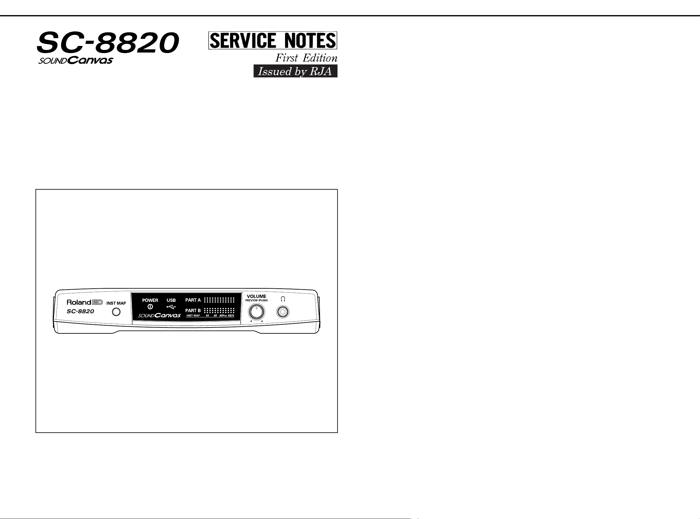
LOCATION OF CONTROLS
EXPLODED VIEW
PARTS LIST
IDENTIFYING VERSION NUMBER
VERSION UP
TEST MODE
BLOCK DIAGRAM
CIRCUIT BOARD
CIRCUIT DIAGRAM
111111111111111111111111111111111111111111111111111111111111111#
111111111111111111111111111111111111111111111111#
111111111111111111111111111111111111111111111111111111111111111#
1111111111111111111111111111111111111111111111111111111111111111111111111#
111111111111111111111111111111111111#
11111111111111111111111111111111111111111111111111111111111111111111111#
111111111111111111111111111111111111111111111111111111111111111111111111#
111111111111111111111111111111111111111111111111111111111111111#
1111111111111111111111111111111111111111111111111111111111111111#
1111111111111111111111111111111111111111111111111111111111111#
目次 Page
目次目次
主な仕様
パネル配置図
分解図
パーツリスト
バージョンナンバーの確認方法
バージョンアップ
テストモード
ブロック図
基板図
回路図
Page
PagePage
111111111111111111111111111111111111111111111111111111111111111111111 #
11111111111111111111111111111111111111111111111111111111111111 #
111111111111111111111111111111111111111111111111111111111111111111111111 #
11111111111111111111111111111111111111111111111111111111111111 #
111111111111111111111111111111111 #
111111111111111111111111111111111111111111111111111 #
1111111111111111111111111111111111111111111111111111111111 #
11111111111111111111111111111111111111111111111111111111111111111 #
1111111111111111111111111111111111111111111111111111111111111111111 #
11111111111111111111111111111111111111111111111111111111111111111 #
9∼10
11∼17
5∼6
6∼7
SPECIFICATIONS 主な仕様
Model: Sound Canvas SC-8820
(General MIDI System / GS Format)
• Number of parts
32
• Maximum Polyphony
64 (voices)
1
2
3
4
5
8
• Internal Sounds
Sound Maps: 4 (SC-8820, SC-88Pro, SC-88, SC-55)
Preset Sounds : 1608
Drum sound sets : 63
User sounds :
User drum sound sets:
•Effects
Reverb (8 types)
Chorus (8 types)
Delay (10 types)
2 Band Equalizer
Insertion Effect (64 types)
• Display
Power indicater
USB indicater
Part level indicater (PART A, PART B)
−
−
主な仕様
主な仕様主な仕様
製品名:サウンド・キャンバス
(GMシステム/GSフォーマット対応)
●パート数
32
●最大同時発音数
音(ボイス)
64
●内蔵音色
音色マップ:
プリセット音色数:
ドラム音色セット:
ユーザー音色数 :なし
ユーザー・ドラム音色セット:なし
●エフェクト
リバーブ(8種類)
コーラス(8種類)
ディレイ(10種類)
バンド・イコライザー
2
インサーション・エフェクト(64種類)
●ディスプレイ
パワー・インジケーター
インジケーター
USB
パート・レベル・インジケーター
4(SC-8820, SC-88Pro, SC-88, SC-55)
SC-8820
1608
63
(PART A, PART B)
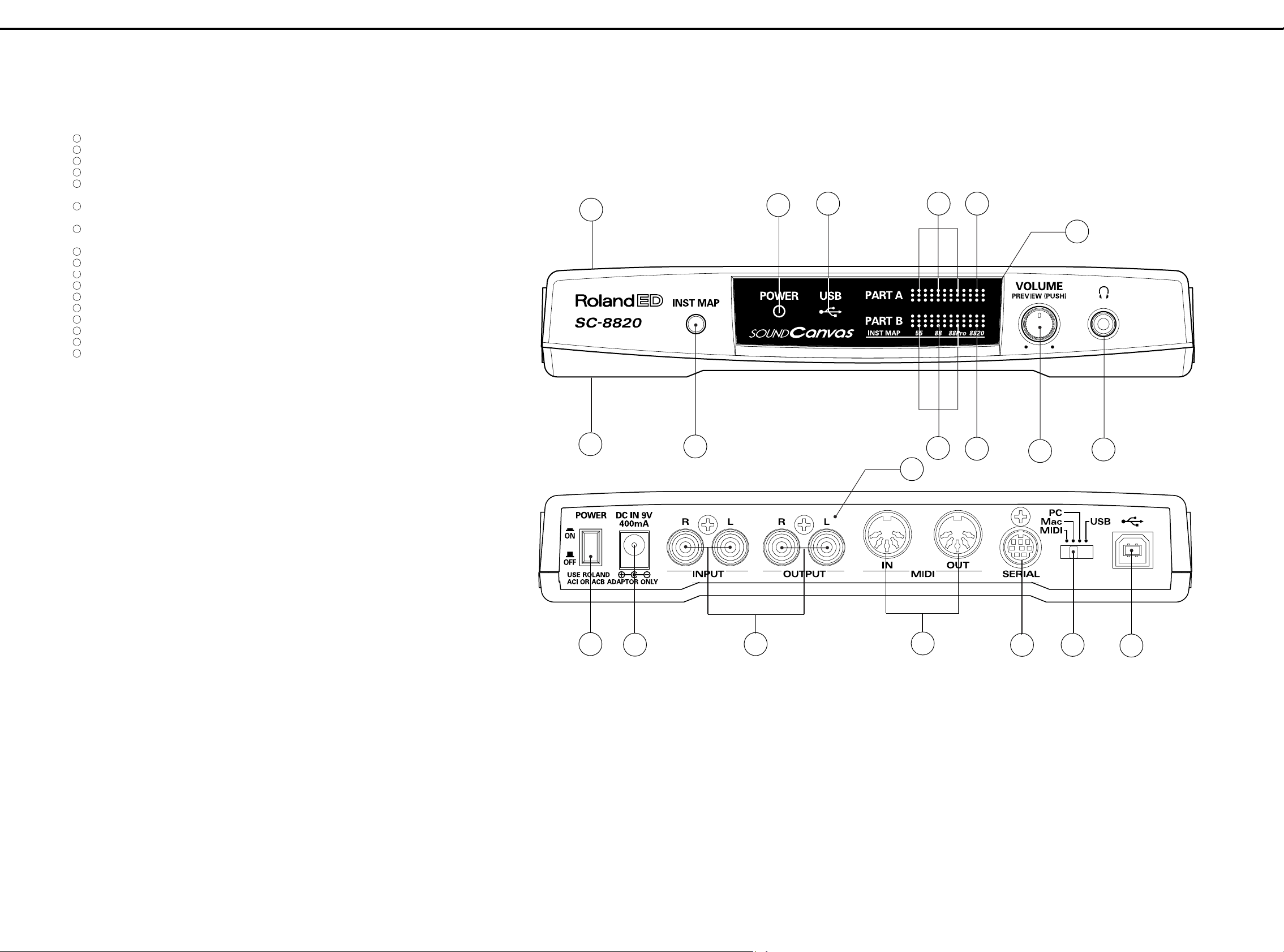
•Connectors
MIDI connectors (IN 1, OUT 1)
Audio Input jack (L, R)
Audio Output jack (L, R)
Headphones jack
Serial connector
USB connector
•Power Supply
DC 9V (AC Adaptor)
•Power Consumption
400 mA
•Dimensions
203 (W) x 159 (D) x 35 (H) mm
8 (W) x 6-1/4 (D) x 1-3/8 (H) inches
• Weight
0.4 kg
14 oz
•Accessories
AC ADAPTOR ACI-120C (#00905767)
ACI-230C (#01018312)
ACB-230E(#01458278)
ACB-240A(#12449549)
Owner's manual Japanese (#71560745)
English (#71560812)
CD-ROM DRIVER English (#71569578)
●接続端子
コネクター
MIDI
インプット・ジャック(ステレオ)
アウトプット・ジャック(ステレオ)
ヘッドホン・ジャック
シリアル・コネクター
コネクター
USB
●電源
DC 9 V(AC
●消費電流
400 mA
●最大外形寸法
(幅)
203
●重量
0.4 kg
●付属品
アダプター
AC
取扱説明書 和文
取扱説明書 英文
保証書
(#40232334)(JAPAN ONLY)
CD-ROM DRIVER (
(IN A, IN B)
アダプター)
(奥行)
x 159
ACI-100C (#00905756)
(#71560745)
(#71560812)
x 35
日本語版
(高さ)
)(#71569567)
mm
Copyright 1999 ROLAND CORPORATION
All rights reserved. No part of this publication may be reproduced in any form without the written permisson of
ROLAND CORPORATION.
本書の一部、もしくは全部を無断で複写・転載することを禁じます。
17059999
Printed in Japan (GE0) (CR)
* In the interest of product improvement, the
specifications and/or appearanceof this unit are subject
to change without prior notice.
●別売品
コンピューター・ケーブル
RSC-15N(D-sub25
RSC-15AT(D-sub9
RSC-15APL(Apple Macintosh
※製品の仕様、および外観は、改良のため予告なく変更す
ることがあります。
ピン・シリアル端子用)
ピン・シリアル端子用)
用)
1
Page 2
Nov, 1999SC-8820
1 2 3 4 5 6 7 8 9 10111213141516171819202122232425262728
#2#
LOCATION OF CONTROLS
A
NO.PART CODE PART NAME DESCRIPTION Q'TY
B
1
02011490 TOP CASE 1
2
02011823 BOTTOM CASE 1
3
02011834 DISPLAY COVER 1
4
C
D
E
F
G
02018089 REAR PANEL 1
5
22495521 BUTTON 249-521 1
13129369 PUSH SWITCH SPUN19430A 1
6
01340412 P R-KNOB SF-A BLK/LCG 1
13289209 9M/M ROTARY POTENTIOMETER RK0971214 10KBX2 (W/SWITCH) 1
7
22495607 R-BUTTON 249-607 1
13119710 SWITCH SKHQFM 1
8
02015956 SLIDE SWITCH SSSF124-S06N0 1
9
13429626 CONNECTOR (5P-DIN) M-S2 M1707 2
10
13429911 DIN JACK TCS7927-28-401 (RS422) 1
11
01124845 RCA(PIN) JACK YKC21-3105 WITH FRAME GROUND 2
12
13449433 3.5MM JACK STEREO YKB21-5130 1
13
13449720 DC JACK HEC2305-01-250 1
14
01459945 USB CONNECTOR YKF45-0002 1
15
00348490 LED (RED) SLR-325VCT31 1
16
00560745 LED (GREEN) SLR-325MCT31 6
17
01787045 LED (ORANGE) SLR-325DCT31 3
#2#
パネル配置図
パネル配置図
#2##2#
パネル配置図パネル配置図
1
15
17
16 17
3
H
I
J
K
L
M
N
O
P
2
5
13
7
11
4
9
16
17
6
12
8
810
14
Q
R
S
T
U
2
Page 3
Nov, 1999 SC-8820
1 2 3 4 5 6 7 8 9 10 11 12 13 14 15 16 17 18 19 20 21 22 23 24 25 26 27 28
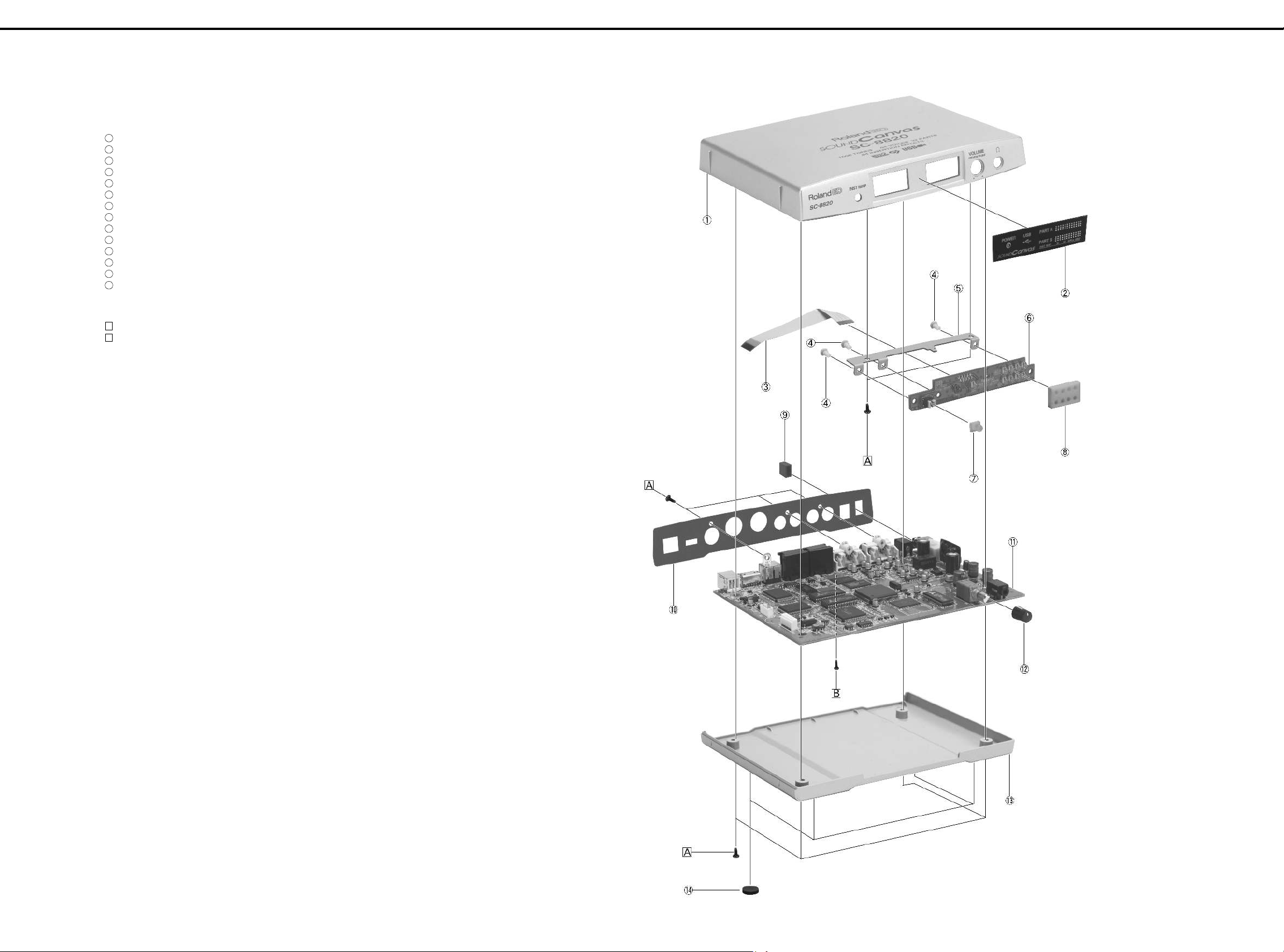
EXPLODED VIEW / 分解図
A
No. PART CODE PART NAME DESCRIPTION
1
B
C
D
E
02011490 TOP CASE
2
02011834 DISPLAY COVER
3
02120778 FPC CABLE FPC BNCD-P=1.25-K-10-90
4
40016590 NYLON RIVET NRP-345 BLACK
5
02018090 PANEL BOARD HOLDER
6
71565345 PANEL BOARD ASSY
7
22495607 R-BUTTON 249-607
8
02124767 ISOLATOR LED MASK
9
22495521 BUTTON 249-521
10
02018089 REAR PANEL
11
71560778 MAIN BOARD ASSY (EXG)
12
01340412 P R-KNOB SF-A BLK/LCG
13
02011823 BOTTOM CASE
14
02120012 FOOT D12 T2 ZULEN XCK020
分解図
分解図分解図
F
[SCREW ]
No. PART CODE PART NAME DESCRIPTION
A
G
40011312 SCREW M3X8 BINDING TAPTITE P FE BZC
B
40011490 SCREW M3X6 PAN MACHINE W/SW BZC
H
I
J
K
L
M
N
O
P
Q
R
S
T
U
3
Page 4
PARTS LIST /パーツリスト
SAFETY PRECAUTIONS:
The parts marked have
safety-related characteristics.
Use only listed parts for
replacement.
安全上の注意:
が付いている部品は、安全
上特別な規格でつくられたも
のです。
交換の際は、注意をよく読み、
指定された部品番号以外の部
品は使わないようにして下さ
い。
NOTE: The parts marked # are new. (initial parts)
注意:#が付いた部品は新規部品です。
CASING / ケース
# 02011823 BOTTOM CASE 1
# 02011490 TOP CASE 1
# 02011834 DISPLAY COVER 1
CHASSIS / シャーシ
# 02018090 PANEL BOARD HOLDER 1
# 02018089 REAR PANEL 1
KNOB, BUTTON / つまみ、ボタン
SWITCH / スイッチ
# 02015956 SSSF124-S06N0 SLIDE SWITCH SW1 on Main 1
JACK, SOCKET / ジャック、ソケット
PCB ASSY / 基板完成品
# 71565345 PANEL BOARD ASSY 1
# 71560778 MAIN BOARD ASSY (EXG) 1
IC / 集積回路
# 02010623 M37640E8FP IC (8BIT CPU) IC2 on Main 1
# 02015367 HD64F7017F28 IC (32BIT CPU) IC1 on Main 1
# 02016156 MASK ROM MX23C6410RC-12 IC (MASK ROM) IC39 on Main 1
# 02121512 23C064040LGY-541-MKH IC (MASK ROM) IC8 on Main 1
# 01897201 PCM1716E IC (AD/DA) IC14 on Main 1
# 01899790 UPC29L33T-E2 IC (REGULATOR) IC18 on Main 1
# 02017501 BP5220 SWITCHING REGULATOR IC20 on Main 1
TRANSISTOR / トランジスター
# 02017512 PW MOSFET 2SJ325-Z-E1 TRANSISTOR Q10 on Main 2
ケース
ケースケース
シャーシ
シャーシシャーシ
22495521 BUTTON 249-521 POWER 1
01340412 P R-KNOB SF-A BLK/LCG VOLUME 1
22495607 BUTTON 249-607 INST MAP 1
スイッチ
スイッチスイッチ
13119710 SKHQFM SWITCH SW1 on Panel 1
13129369 SPUN19430A PUSH SWITCH SW4 on Main 1
13159187 SSSS2-22-01 SLIDE SWITCH SW2 on Main 1
13429626 M-S2 CONNECTOR (5P-DIN) JK3, JK4 on Main 2
13429911 TCS7927-28-401 (RS422) DIN JACK JK2 on Main 1
01124845 YKC21-3105 WITH FRAME GROUND RCA(PIN) JACK JK5, JK6 on Main 2
13449433 STEREO YKB21-5130 3.5MM JACK JK8 on Main 1
13449720 HEC2305-01-250 DC JACK JK7 on Main 1
01459945 YKF45-0002 USB CONNECTOR JK1 on Main 1
基板完成品
基板完成品基板完成品
E
集積回路
集積回路集積回路
15239206 MB87837PF-G-BND IC (LSP) IC4 on Main 1
01679978 RA09-002 (XP6) IC (CUSTOM) IC3 on Main 1
01560289 TC55257DFL-55L(EL) IC (SRAM) IC12 on Main 1
01899556 DRAM AS4C256K16E0-50JCTR IC (DRAM) IC9-IC11 on Main 3
01891445 UPD23C128040LGY-823-MJH IC (MASK ROM) IC7 on Main 1
01561945 LH28F160S5T-L70 IC (FLASH MEMORY) IC5 on Main 1
15249121 TC7W04F(TE12L) IC (CMOS) IC22, IC40 on Main 2
15259887 TC7SU04F(TE85L) IC (CMOS) IC24 on Main 1
15249111 TC7WU04F(TE12L) IC (CMOS) IC23, IC27 on Main 2
15249116T0 TC7W00F(TE12L) IC (CMOS) IC36 on Main 1
15259758T0 TC74HC175AF(EL) IC (CMOS) IC30 on Main 1
15259884 TC7S08F(TE85L) IC (CMOS) IC29 on Main 1
15259885 TC7S32F(TE85L) IC (CMOS) IC28 on Main 1
00564545 TC74VHC04F(EL) IC (CMOS) IC35 on Main 1
15289105 UPC4570G2-E2 IC (BIPOLAR OP AMP) IC31, IC32 on Main 2
15189261 M5218AFP-600E IC (BIPOLAR OP AMP) IC33, IC34 on Main 2
15289404 IR3M03N2-T2 IC (REGULATOR) DC-DC IC21 on Main 1
15289712 M5M34051FP-42A IC (DRIVER) IC16 on Main 1
01675012 M62008FP-600 IC (RESET) IC17 on Main 1
15199937 M51953BFP-600C IC (RESET IC) IC19 on Main 1
!
15289125 PC-410KT 178FAY IC (PHOTO COUPLER) IC15 on Main 1
15309101 2SA1037KR T146 QRS TRANSISTOR Q3 on Main 1
15319105 2SC3326-A TRANSISTOR Q1, Q2 on Main 2
15329503 DTA124EK T146 DIGITAL TRANSISTOR Q5-Q7, Q11 on Main 4
/パーツリスト
/パーツリスト/パーツリスト
つまみ、ボタン
つまみ、ボタンつまみ、ボタン
ジャック、ソケット
ジャック、ソケットジャック、ソケット
トランジスター
トランジスタートランジスター
SAFETY PRECAUTIONS:
The parts marked have safety-related characteristics. Use only listed parts for replacement.
QTY PART NUMBER DESCRIPTION MODEL NUMBER
Ex. 10 22575241 Sharp Key C-20/50
15 2247017300 Knob (orange) DAC-15D
Failure to completely fill the above items with correct number and description will result in delayed or
even undelivered replacement.
パーツ発注に関するお願い
パーツ発注に関するお願い
パーツ発注に関するお願いパーツ発注に関するお願い
オーダーシートには、必ず下記の4項目は正確に記入して下さい。(例外は除く)
もし記入漏れ、誤記等が有る場合、必要部品が発送出来なかったり、大幅な遅れの原因になります。
ご協力をお願いします。
必要数
例
) 10 22575241 Sharp Key C-20/50
15 2247017300 Knob (orange) DAC-15D
パーツナンバー 品 名 使用機種
Nov, 1999SC-8820
DIODE / ダイオード
ダイオード
ダイオードダイオード
00348490 SLR-325VCT31 LED (RED) LED10 on Panel 1
00560745 SLR-325MCT31 LED (GREEN) LED1-LED3, LED5-LED7 on Panel 6
# 01787045 SLR-325DCT31 LED (ORANGE) LED4, LED8, LED9 on Panel 3
00673789 SB20-03P-TD SCHOTTKY DIODE D11 on Main 1
01017512 RB411D T146 SCHOTTKY DIODE D1 on Main 1
15339412 U1BC44(TE12L) DIODE D12 on Main 1
01121323 DA204U T106 ARRAY DIODE DA2, DA3 on Main 2
01126823 RD20S-T1 B ZENER DIODE D3-D8, on Main 6
RESISTOR
# 00567467 RPC05T 274 J MTL.FILM RESISTOR Chip on Main 1
POTENTIOMETER / ボリューム
CAPACITOR / コンデンサー
# 01675201 GRM39CH270J50PT CERAMIC CAPACITOR Chip on Main 2
# 01674401 ECUV1H331JCV CERAMIC CAPACITOR Chip on Main 3
INDUCTOR, COIL, FILTER / インダクター、コイル、フィルター
CRYSTAL, RESONATOR / クリスタル、発振子
RELAY / リレー
# 02120856 G6E-134P-US DC5V RELAY RL1 on Main 1
CONNECTOR / コネクター
# 01909589 10FE-BT-VK-N CONNECTOR CN1 on Panel, CN1 on Main 1 +1
WIRING, CABLE / ワイヤリング、ケーブル
# 02120778 FPC CABLE FPC BNCD-P=1.25-K-10-90 CN1 on Panel to CN1 on Main 1
/ 抵抗
抵抗
####
抵抗抵抗
00567412 RPC05T 104 J MTL.FILM RESISTOR Chip on Main 11
01011256 SR73K2ETD 0.47JOHM 1/2W MTL.FILM RESISTOR Chip on Main 1
01011856 RPC05T 0R0 J MTL.FILM RESIST0R Chip on Main 2
00567112 RPC05T 471 J MTL.FILM RESISTOR Chip on Main 4
00566912 RPC05T 220 J MTL.FILM RESISTOR Chip on Main 3
01345434 MCR18 EZH J 390 MTL.FILM RESISTOR Chip on Main 1
15399709 1/4W MCR25JZH 68 MTL.FILM RESISTOR Chip on Main 2
00566934 RPC05T 330 J MTL.FILM RESISTOR Chip on Main 1
00567134 RPC05T 681 J MTL.FILM RESISTOR Chip on Main 4
00567245 RPC05T 472 J MTL.FILM RESISTOR Chip on Main 3
00567190 RPC05T 222 J MTL.FILM RESISTOR Chip on Main 1
00567178 RPC05T 152 J MTL.FILM RESISTOR Chip on Main 1
00567156 RPC05T 102 J MTL.FILM RESISTOR Chip on Main 7
15419701 RR1220P-103-D 10KOHM (CHIP) MTL.FILM RESISTOR Chip on Main 4
00567289 RPC05T 103 J MTL.FILM RESISTOR Chip on Main 22
00897234 RR1220P-183-D 18K(D) (CHIP) MTL.FILM RESISTOR Chip on Main 4
00567301 RPC05T 153 J MTL.FILM RESISTOR Chip on Main 5
00567212 RPC05T 332 J MTL.FILM RESISTOR Chip on Main 1
01018212 RR1220Q-330-D MTL.FILM RESISTOR Chip on Main 2
00567323 RPC05T 223 J MTL.FILM RESISTOR Chip on Main 11
00567267 RPC05T 682 J MTL.FILM RESISTOR Chip on Main 1
00567023 RPC05T 101 J MTL.FILM RESISTOR Chip on Main 3
00567345 RPC05T 333 J MTL.FILM RESISTOR Chip on Main 4
00567501 RPC05T 474 J MTL.FILM RESISTOR Chip on Main 2
00567556 RPC05T 105 J MTL.FILM RESISTOR Chip on Main 2
00567067 RPC05T 221 J MTL.FILM RESISTOR Chip on Main 6
15399301 RPC10T 0R0 J MTL.FILM RESISTOR Chip on Main 2
15399445 RPC10T 104 J 1/10W MTL.FILM RESISTOR Chip on Main 1
15399975 RCE9A223JA (22KOHM X8) RESISTOR ARRAY RA8, RA9, RA16 on Main 3
15409113 EXBV8V103JV RESISTOR ARRAY RA1 on Main 1
15409115 EXBV8V223JV RESISTOR ARRAY RA3, RA10-RA13 on Main 5
00909801 EXBV8V220JV RESISTOR ARRAY RA2, RA4-RA7 on Main 5
00126112 EXBV8V101JV RESISTOR ARRAY RA14, RA15 on Main 2
ボリューム
ボリュームボリューム
13289209 RK0971214 10KBX2 (W/SWITCH) 9M/M ROTARY POTENTIOMETER VR1 on Main 1
コンデンサー
コンデンサーコンデンサー
01674189 ECUV1H120JCV CERAMIC CAPACITOR Chip on Main 2
01674190 ECUV1H150JCV CERAMIC CAPACITOR Chip on Main 2
01674234 ECUV1H330JCV CERAMIC CAPACITOR Chip on Main 7
15359225 GRM40B104K25PT CERAMIC CAPACITOR Chip on Main 1
01674423 ECUV1H471JCV CERAMIC CAPACITOR Chip on Main 1
01674445 ECUV1H681JCV CERAMIC CAPACITOR Chip on Main 1
01675167 GRM39CH100D50PT CERAMIC CAPACITOR Chip on Main 1
01675278 GRM39CH101J50PT CERAMIC CAPACITOR Chip on Main 3
00907689 GRM40F105Z16PT CERAMIC CAPACITOR Chip on Main 11
01674712 ECJ1VF1A105Z CERAMIC CAPACITOR Chip on Main 1
00567978 GRM39F104Z25PT CERAMIC CAPACITOR Chip on Main 57
00567945 GRM39B103K50PT CERAMIC CAPACITOR Chip on Main 1
00567823 GRM39B102K50PT CERAMIC CAPACITOR Chip on Main 4
01898423 ECHU1H222JX5 POLYEST. CAPACITOR Chip on Main 2
01899545 ECHU1H391JX5 POLYEST. CAPACITOR Chip on Main 2
15369109 ECEV0JA101SP CHEMICAL CAPACITOR Chip on Main 2
01340845 ECA0JM222B CHEMICAL CAPACITOR C57 on Main 1
15369152 ECEV1CA100SR CHEMICAL CAPACITOR Chip on Main 20
13629624S0 6SC10M+T (OS) 6.3V10 CHEMICAL CAPACITOR C6, C14 on Main 2
13639557M0 ECA1CM102B CHEMICAL CAPACITOR C54 on Main 1
01893223 TCFGA1A225K8R TANTALUM CAPACITOR C122 on Main 1
インダクター、コイル、フィルター
インダクター、コイル、フィルターインダクター、コイル、フィルター
01676023 SBCP-87331H CHOKE COIL L2, L5, L7 on Main 3
01340834 EXCML20A390 FERRITE-BEAD Chip on Main 25
00903167 N2012Z601T02 (CHIP) FERRITE-BEAD Chip on Main 3
クリスタル、発振子
クリスタル、発振子クリスタル、発振子
00891801 MA-406 24.000MHZ TE24 CRYSTAL X3 on Main 1
00901912 MA-406 24.576MHZ TE24 CRYSTAL X2 on Main 1
01126267 MA-406 7.056MHZ CRYSTAL X1 on Main 1
リレー
リレーリレー
!
コネクター
コネクターコネクター
ワイヤリング、ケーブル
ワイヤリング、ケーブルワイヤリング、ケーブル
4
Page 5
Nov, 1999 SC-8820
SCREW / ねじ類
PACKING / 梱包材
# 02011545 PACKING CASE JAPANESE 1
# 02019201 PACKING CASE ENGLISH 1
# 02122867 PAD L/R 2
# 02122878 PAD CENTER 1
# 02122889 PAD AC ADAPTOR 1
MISCELLANEOUS
# 02124767 ISOLATOR LED MASK 1
ACCESSORIES (STANDARD) / 標準付属品
# 71569567 DRIVER CD-ROM JAPANESE 1
# 71569578 DRIVER CD-ROM ENGLISH 1
# 71560745 OWNER'S MANUAL JAPANESE 1
# 71560812 OWNER'S MANUAL ENGLISH 1
ねじ類
ねじ類ねじ類
40011312 SCREW M3X8 BINDING TAPTITE P FE BZC 9
40011490
40016590 NYRON RIVET NRP-345 BLACK RIVET 3
02120012 FOOT D12 T2 ZULEN XCK020 4
!
00905756 AC ADAPTOR ACI-100C 1
!
00905767 AC ADAPTOR ACI-120C 1
!
01018312 AC ADAPTOR ACI-230C 1
!
01458278 AC ADAPTOR ACB-230E 230VE(DC9V.1200MA) 1
!
12449549 AC ADAPTOR ACB-240(A) *EXP ONLY* 1
******** DTM REGISTRATION CARD 1999 1
40232334
梱包材
梱包材梱包材
セムス
M3x6 BZC SCREW 1
/ その他
その他
####
その他その他
標準付属品
標準付属品標準付属品
保証書
JAPAN ONLY 1
IDENTIFYING VERSION NUMBER ////バージョンナンバーの確認方法
♦
Version Displaying Procedure
1. Entering the version display mode
•
Hold down Preview and switch power on.
•
While the Map key is lit, press Preview once, then press
the Map key.
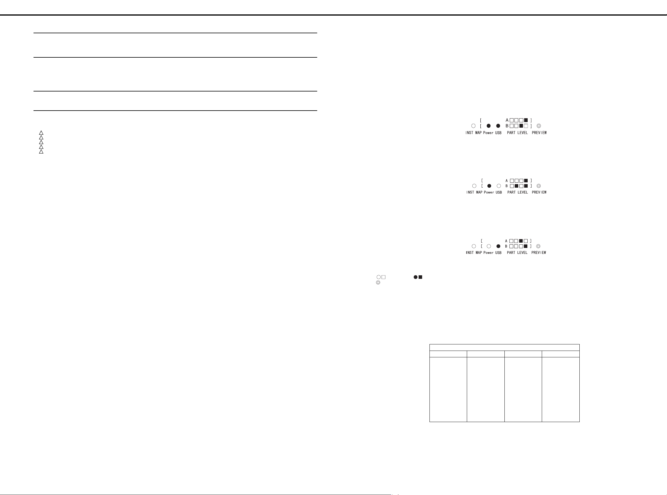
2. CPU ROM version display
Immediately after the unit is placed in the version display
mode by the operation in step 1, the CPU ROM version is
displayed. The Power and USB indicators are lit, and Part
A and Part B of the PART LEVEL indicator denote the
major number and minor number, respectively, in 4 bits.
For example, Ver 1.02 is indicated as follows:
Press the MAP key to shift to program ROM version
display.
3. Program ROM version display
The Power indicator is lit and the PART LEVEL indicator
denotes the version. For example, Ver 1.05 is indicated
as follows:
バージョンナンバーの確認方法
バージョンナンバーの確認方法バージョンナンバーの確認方法
◆バージョン表示方法
◆バージョン表示方法
◆バージョン表示方法◆バージョン表示方法
1.
バージョン表示モードに入る
バージョン表示モードに入る
バージョン表示モードに入るバージョン表示モードに入る
・
Previwe
・
Map Key
の後
2. CPU
1.
内
ジケータと
ル・インジケータの A がメジャー番号、B がマイナー番
号を
例えば
MAP Key で Program ROM
3. Program ROM
パワー・インジケータが点灯し、パートレベル・インジ
ケータがバージョンを表しています。例えば
以下のようになります。
を押しながら電源を立ち上げます。
が点灯している間に、
Map Key
内内内内
の操作でバージョン表示モードに入った直後は、
ROM
4bit
Ver1.02
を押して下さい。
ROM
バージョン表示
バージョン表示
バージョン表示バージョン表示
のバージョン表示になっています。パワー・イン
接続インジケータが点灯し、パートレベ
USB
で表示します。
ならば次のようになります。
バージョン表示
バージョン表示
バージョン表示バージョン表示
Previwe
バージョン表示に移ります。
を1回押し、そ
CPU
なら
Ver1.05
Press the MAP key to shift to UIPC version display.
4. UIPC version display
The USB indicator is lit and the PART LEVEL indicator
denotes the version. For example, Ver 2.01 is indicated
as follows:
Press the MAP key to return to CPU ROM version
display.
Note: denotes off, on, and * blink.
denotes the potentiometer knob.
VERSION UP ////バージョンアップの方法
♦
Items to Be Prepared
•
Programmable controller (e.g. MC-80)
•
Update disks (#17048429)
バージョンアップの方法
バージョンアップの方法バージョンアップの方法
SMF disk (2DD) containing Update Data: 2 disks (2DD x 4) /
アップデート用
アップデート用
アップデート用アップデート用
Disk #1 Disk #2 Disk #3 Disk #4
Update Date
(1 or 4)
SMF
データディスク(
データディスク(
データディスク(データディスク(
Update Data
(2 of 4)
Update Data
(3 of 4)
MAP Key で UIPC
4. UIPC
注)◯□は消灯、●■は点灯、*は点滅を表します。
◆用意するもの
◆用意するもの
◆用意するもの◆用意するもの
・シーケンサー(
・アップデートディスク(
バージョン表示
バージョン表示
バージョン表示バージョン表示
接続インジケータが点灯し、パートレベル・インジ
USB
ケータがバージョンを表しています。例えば
以下のようになります。
MAP Key で CPU 内ROM
◎は
Volume
2DD x 4
枚)
枚)
枚)枚)
Update Data
(4 of 4)
バージョン表示に移ります。
バージョン表示に戻ります。
ツマミ。
等)
MC-80
#17048429
Ver2.01
)
なら
ERASE.MID
SC882_00.MID
SC882_01.MID
SC882_02.MID
SC882_03.MID
SC882_04.MID
SC882_05.MID
SC882_06.MID
SC882_07.MID
•
MIDI cable
♦
Connection Method
•
Connect MIDI OUT of the PLC and MIDI IN of the SC8820 by the MIDI cable.
SC882_08.MID
SC882_09.MID
SC882_10.MID
SC882_11.MID
SC882_12.MID
SC882_13.MID
SC882_14.MID
SC882_15.MID
SC882_16.MID
SC882_17.MID
SC882_18.MID
SC882_19.MID
SC882_20.MID
SC882_21.MID
SC882_22.MID
SC882_23.MID
・
MIDI
◆接続方法
◆接続方法
◆接続方法◆接続方法
・シーケンサーの
ケーブルにて接続します。
SC882_24.MID
SC882_25.MID
SC882_26.MID
SC882_27.MID
SC882_28.MID
SC882_29.MID
SC882_30.MID
SC882_31.MID
ケーブル
MIDI OUTとSC-8820のMIDI INをMIDI
5
Page 6
Nov, 1999SC-8820
♦
Updating procedure
1. Hold down Preview and switch power on.
2. While the Map key is lit, press Preview three times, then
press the Map key.
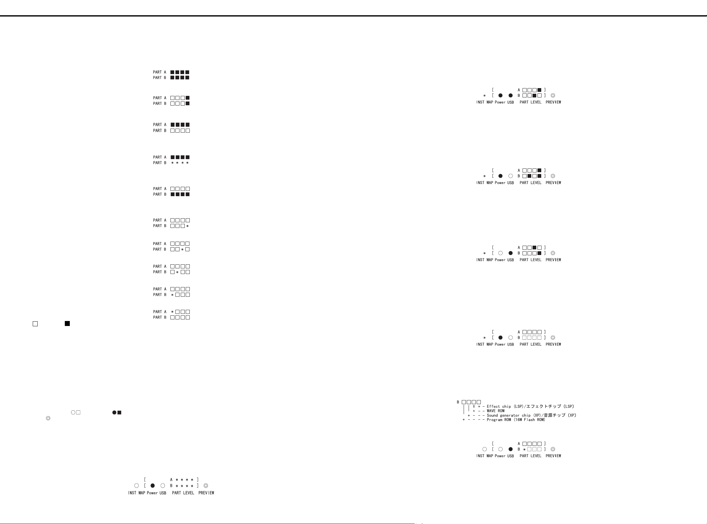
This lights up all the Level meters.
3. Send "erase.mid". Erase starts and the two rightmost
meters are lit.
4. When erase is finished, four LEDs of PART A turn on.
5. In this state, UPDATE SMFs can be received.
When UPDATE SMFs (32 SMFs in all) are sent, four LEDs
of PART B start blinking at short intervals.
6. UPDATE is complete when the transmission of the 32nd
SMF is finished and the four LED of PART B turn on.
♦
Error Indications during Updating
•
Device error
•
Erase failure
◆アップデート方法
◆アップデート方法
◆アップデート方法◆アップデート方法
1. Previwe
2. Map Key
その後
すると、
3.erase.mid
消去が終了すると、
4.
この状態で、
5.
UPDATE SMF(全32 SMF
つの
6. 32
が点灯したら、
Update
◆◆◆◆
・デバイスエラー
・消去失敗
を押しながら電源を立ち上げます。
が点灯している間に、
Map Key
Level Meter
を送る。と消去を始めて右端2つが点灯する。
UPDATE SMF
が細かく点滅を始めます。
LED
番目の
を送信終了して、
SMF
UPDATE
時のエラー表示
時のエラー表示
時のエラー表示時のエラー表示
を押す。
が全て点灯する。
PART A
)を送信すると、
完了。
LED
PART B
を3回押して、
が点灯します。
PART B
の4つの
LED
Previwe
の4つの
が受信できるようになる。
の4
2. CPU ROM version display
Immediately after the unit is placed in the test mode by
the operation in step 1, the CPU ROM version is
displayed. The Power and USB indicators are lit, and Part
A and Part B of the PART LEVEL indicator denote the
major number and minor number, respectively, in 4 bits.
For example, Ver 1.02 is indicated as follows:
[INST MAP] blinks to indicate that the unit can shift to the
next test item.
Press the MAP key to proceed to the next test.
3. Program ROM version display
The Power indicator is lit and the PART LEVEL indicator
denotes the version. For example, Ver 1.05 is indicated
as follows:
[INST MAP] blinks to indicate that the unit can shift to the
next test item.
Press the MAP key to proceed to the next test.
4. UIPC version display
The USB indicator is lit and the PART LEVEL indicator
denotes the version. For example, Ver 2.01 is indicated
as follows:
2. CPU
3. Program ROM
4. UIPC
ROM
内内内内
の操作でテストモードに入った直後は、
1.
のバージョン表示になっています。パワー・インジケー
タと
USB
インジケータの A がメジャー番号、B がマイナー番号
を
4bit
例えば
[INST MAP]
を表しています。
MAP Key
パワー・インジケータが点灯し、パートレベル・インジ
ケータがバージョンを表しています。例えば
ら以下のようになります。
[INST MAP]
を表しています。
MAP Key
バージョン表示
バージョン表示
バージョン表示バージョン表示
接続インジケータが点灯し、パートレベル・インジ
USB
ケータがバージョンを表しています。例えば
ら以下のようになります。
バージョン表示
バージョン表示
バージョン表示バージョン表示
CPU 内ROM
接続インジケータが点灯し、パートレベル・
で表示します。
ならば次のようになります。
Ver1 .0 2
は点滅していて次のテスト項目に移れること
を押すと次のテストに進みます。
バージョン表示
バージョン表示
バージョン表示バージョン表示
は点滅していて次のテスト項目に移れること
を押すと次のテストに進みます。
Ve r1 .0 5
Ve r2 .0 1
な
な
•
Write failure
•
Checksum error
•
MIDI error
Note: denotes off, on, and * blink.
TEST MODE //// テストモード
The test mode of the SC-8820 may be executed in either of the
following two ways:
1. Executed on the SC-8820 alone.
2. The SC-8850 is used.
When the test mode is executed in the method "2. The SC-8850
is used", the test results are displayed on the LCD for ease of
identification.
テストモード
テストモードテストモード
1. Executed on the SC-8820 alone.
Note: In the diagrams, denotes off, on, and *
blink. denotes the potentiometer knob.
1. Entering the test mode
•
Set the computer switch on the rear panel to "Mac".
•
Hold down Preview and switch power on.
•
While the Map key is lit, press Preview twice, then press
the Map key.
•
If all the PART LEDs blink as shown below, the computer
switch setting is wrong. Restart from step 1.
・書き込み失敗
・チェックサムエラー
・
エラー
MIDI
注)□は消灯、■は点灯、*は点滅を表します。
SC-8820
なお、「2.
した場合、
なっています。
1.
1.
1.1.
注)図の、◯□は消灯、●■は点灯、*は点滅を表します。◎
のテストモード以下の2種類あります。
1.
SC-8820
2.
SC-8850
SC-8820
は
1.
テストモードに入る
テストモードに入る
テストモードに入るテストモードに入る
・背面のコンピュータースイッチを
・
・
・次の図のように、
単体で行う。
を使用して行う。
SC-8850
LCD
Volume
Previwe
Map Key
その後
コンピュータースイッチの設定が間違えています。
の最初からやり直して下さい。
を使用して行う」でテストモード を実行
にテスト結果が表示される為より分かりやすく
単体で行う
単体で行う
単体で行う単体で行う
ツマミ。
を押しながら電源を立ち上げます。
が点灯している間に、
Map Key
を押して下さい。
PA RT LED
"Mac"
Previwe
がすべて点滅した場合は、
に設定します。
を2回押し、
1.
[INST MAP] blinks to indicate that the unit can shift to the
next test item.
Press the MAP key to proceed to the next test.
5. Device test
The flash ROM, XP chip, wave ROM and LSP chip are
tested.
If all are OK, [Power] turns on as shown below.
[INST MAP] blinks to indicate that the unit can shift to the
next test item.
Press the MAP key to proceed to the next test.
If any of the above devices is not good, [USB] is lit and
the PART B indicator LED corresponding to the faulty
device blinks. The relationships between faulty devices
and PART B indicator LEDs are as follows.
For example, if the flash ROM is not good, the following
display is provided.
(If the result is not good, you can proceed to the next test
by pressing the MAP key twice.)
[INST MAP]
を表しています。
MAP Key
5. Device
Flash Rom, XP Chip, Wave Rome, LSP Chip
します。
すべてが、
ます。
[INST MAP]
を表しています。
MAP Key
だった場合、
NG
スに対応する
す。エラーがあったデバイスと
LED
例えば、
します。
(
NG
むことが出来ます)
は点滅していて次のテスト項目に移れること
を押すと次のテストに進みます。
テスト
テスト
テストテスト
の場合は、以下のように
OK
は点滅していて次のテスト項目に移れること
を押すと次のテストに進みます。
PA R T B
の関係は以下の通りです。
Flash Rom が NG
の場合でも、
が点灯し、エラーがあったデバイ
[USB]
インジケータの
MAP Key
PA R T B
だった場合以下のように表示
を2回押すと次のテストに進
のテストを
が点灯し
[Power]
が点滅しま
LED
インジケータの
6
Page 7

Nov, 1999 SC-8820
6. LED on/off check
This test is made to check whether the LEDs turn on and
off properly. First, make sure that all the LEDs are on as
shown below.
Pressing the Preview switch extinguishes the LEDs one
by one in due order, starting from the Map LED. The
result is OK if all the LEDs have turned off. However, if
several or no LEDs have turned off by merely pressing
the Preview switch once, the LED scan line has a
problem (not good).
Press the Map key to proceed to the next test.
7. MIDI check
This test is made to check MIDI IN and OUT. As soon as
this test has started, only [USB] blinks as shown below.
In this status, connect MIDI OUT and MIDI IN of the SC8820 directly by the MIDI cable. If the MIDI functions
properly, [Power] is lit as shown below.
6. LED
点灯チェック
点灯チェック
点灯チェック点灯チェック
がちゃんと点灯、消灯するかのチェックです。ま
LED
ず、 以下のように
すべての
が点灯していることを確認して下さい。
LED
[INST MAP] blinks to indicate that the unit can shift to the
next test item.
If [USB] remains blinking after connection, the serial I/O
of the SC-8820 are not good. (If the result is not good,
you can proceed to the next test by pressing the MAP
key twice.)
9. Sound check
This test is conducted to check whether the SC-8820
Preview
LED
です。ただし、1回
に、
のスキャンラインに問題があります
MAP Key
7. MIDI
MIDI IN, OUT
点では、以下のように
*
この状態のときに、
MIDI
能していると以下のように
スイッチをおすと、
が消灯していきます。すべての
が複数個消えたり、1個も消えない場合は
LED
を押すと次のテストに進みます。
チェック
チェック
チェックチェック
のチェックです。このテストにはいった時
ケーブルで直結してください。うまく、
Map LED
Preview
SC-8820 の MIDI OUTと MIDI IN
スイッチを押しただけなの
のみ点滅しています。
[USB]
[Power]
から順に1個づつ
が消えたら
LED
。
(NG)
が点灯します。
MIDI
OK
LED
を、
が機
sounds properly.
As soon as this test has started, all the indicators are off.
Pressing the Preview switch provides the following
display and you hear a sine wave from the left side.
Check the volume and sound for any abnormality.
Pressing the Preview switch again provides the following
display and now you hear a sine wave from the right side.
Check the volume and sound for any abnormality.
Pressing the Preview switch further provides the following
display and now you hear sine waves from the both
sides.
[INST MAP]
を表しています。
接続しても
シリアル入出力
2回押すと次のテストに進むことが出来ます)
9.
サウンド・チェック
サウンド・チェック
サウンド・チェックサウンド・チェック
SC-8820
このテストにはいった時点ではインジケータは全消灯し
ています。
Preview
らサイン波が聞こえます。
音量、音をチェックして異常がないか聞いてみてくださ
い。
もう一度
て今度は右側からサイン波が聞こえます。
音量、音をチェックして異常がないか聞いてみてくださ
い。
さらに
今度は左右両方からサイン波が聞こえます。
は点滅していて次のテスト項目に移れること
が点滅したままの場合は、
[USB]
の音だしチェックです。
スイッチをおすと以下のように表示して左側か
Preview
Preview
です。(
NG
スイッチをおすと以下のように表示し
スイッチをおすと以下のように表示され
の場合でも、
NG
SC-8820 の
MAP Key
を
[INST MAP] blinks to indicate that the unit can shift to the
next test item.
Press the MAP key to proceed to the next test.
If [USB] remains blinking after connection, the MIDI
function of the SC-8820 is not good. (If the result is not
good, you can proceed to the next test by pressing the
MAP key twice.)
8. Serial check
This test is made to check the computer switch and serial
I/O.
As soon as this test has started, [USB] blinks and one of
the PART B indicator LEDs is on as shown below.
The PART B indicator denotes the computer switch
position.
The relationships between PART B indicator and
computer switch are as indicated below. Namely, the
above diagram shows that the computer switch is in the
Mac position.
First, the computer switch is checked. Move the computer
switch from USB to PC to Mac to MIDI and check that the
corresponding PART B indicator LEDs are lit.
Then, the serial I/O are checked. Connect the serial
check jig to the serial terminal. When the result is good,
[USB] stops blinking and [Power] turns on as shown
below.
[INST MAP]
を表しています。
MAP Key
接続しても
MIDI
(
NG
むことが出来ます)
8.
シリアル・チェック
シリアル・チェック
シリアル・チェックシリアル・チェック
コンピュータースイッチのチェックと、シリアル入出力
のチェックです。
このテストにはいった時点では、以下のように
点滅し、
います。
PA R T B
を示しています。
PA R T B
以下の通りです。すなわち、上図ではコンピュータ・ス
イッチが
まずは、コンピュータースイッチのチェックです。コン
ピュータースイッチを
PA R T B
確認してください。
次は、シリアル入出力のチェックです。シリアルチェッ
ク治具を、シリアル端子に接続してください。うまくい
くと、
点灯します。
は点滅していて次のテスト項目に移れること
を押すと次のテストに進みます。
が点滅したままの場合は、
[USB]
機能が
の場合でも、
[USB]
です。
NG
MAP Key
インジケータの
PA R T B
インジケータは、コンピュータ・スイッチの位置
インジケータとコンピュータ・スイッチの関係は
になっていることを示しています。
Mac
インジケータの対応する
が点滅が消灯して、以下のように
を2回押すと次のテストに進
の1つが点灯して
LED
USB,PC,Mac,MIDI
LED
と切り替えて、
が点灯することを
SC-8820 の
が
[USB]
[Power]
Check the volume and sound for any abnormality.
Further pressing the Preview switch returns to the left
side sound check.
[INST MAP] blinks to indicate that the unit can shift to the
next test item.
Press the MAP key to proceed to the next test.
10. Effect check
This test is performed to check the effect sounds.
As soon as this test has started, all the indicators are off.
Pressing the Preview switch puts the unit in the Insertion
Effect test and provides the following display.
Also, the snares sound as indicated below.
This bold On is a delay sound. Check the sound intervals
and delay sound for abnormality.
Pressing the Preview switch again places the unit in the
Delay (System Effect) test and provides the following
display.
Also, the castanets sound as indicated below.
が
This bold On is a delay sound. Check the sound intervals
and delay sound for abnormality.
音量、音をチェックして異常がないか聞いてみてくださ
い。
Preview
チェックに戻れます。
[INST MAP]
を表しています。
MAP Key
10.
エフェクト・チェック
エフェクト・チェック
エフェクト・チェックエフェクト・チェック
エフェクト音のチェックです。
このテストにはいった時点ではインジケータは全消灯し
ています。
Preview
なり以下の要に表示します。
また、スネアが、以下のように鳴ります。
この、太字のOnがディレイ音です。音の間隔と、ディ
レイ音に異常がないかチェックしてください。
もう一度
Effect)
また、カスタネットが、以下のように鳴ります。
この、太字の
レイ音に異常がないかチェックしてください。
スイッチをさらにおしていくと、左側の音
は点滅していて次のテスト項目に移れること
を押すと次のテストに進みます。
スイッチをおすと、
Preview
のテストになり、以下のように表示します。
スイッチをおすと、
がディレイ音です。音の間隔と、ディ
On
Insertion Effect
Delay (System
のテストに
7
Page 8

Nov, 1999SC-8820
Pressing the Preview switch further places the unit in the
Reverb (System Effect) test and provides the following
display.
The reverberated snares sound periodically. Check
whether the snares are reverberated properly.
Further pressing the Preview switch returns to the
Insertion Effect test.
This ends a series of tests. Switch power off.
2. The SC-8850 is used.
♦
Items to Be Prepared
1. SC-8850
2. MIDI cable
1. How to enter the test mode
1. Connect the SC-8820 and SC-8850.
Connect MIDI OUT of the SC-8820 and MIDI IN 1 of the
SC-8850 by the MIDI cable.
2. Entering the test mode
Set the computer switch on the rear of the SC-8850 to
"MIDI", and switch power on. (After this, the SC-8850 will
never be operated.)
Set the computer switch on the rear of the SC-8820 to
"Mac".
Hold down Preview and switch power on.
While the Map key is lit, press Preview twice, then press
the Map key.
If the LCD shows the following message,
the computer switch setting of the SC-8820 may be
wrong. Restart from step 2.
If nothing appears on the LCD, the computer switch
setting of the SC-8850 may be wrong. Restart from step
2.
2. CPU ROM version display
Immediately after the unit is placed in the test mode by the
operation in step 1, the CPU ROM version is displayed.
さらに
Preview
のテストになり以下の要に表示します。
Effect)
リバーブがかかったスネアが、定期的になります。正し
くリバーブがかかっているか確認してください。
Preview
ンエフェクトテストに戻れます。
これで、一通りのテストが終了です。電源を切って下さ
い。
2. SC8850
◆用意するもの
◆用意するもの
◆用意するもの◆用意するもの
1. SC-8850
ケーブル
2. MIDI
1.
テストモードへの入り方
テストモードへの入り方
テストモードへの入り方テストモードへの入り方
1. SC-8820 と SC-8850
SC-8820 の MIDI OUT と SC-8850 の MIDI IN 1 を MIDI
ケーブルで接続して下さい。
テストモードに入る
2.
SC-8850
設定して電源を立ち上げます。(この後
することはありません。)
SC-8820
設定します。
Previwe
Map Key
の後
Map Key
に、
LCD
が表示された場合は、
チの設定が間違えている可能性があります。2.の最初か
らやり直して下さい。
に、何も表示されない場合は、
LCD
ピュータースイッチが間違えている可能性があります。
の最初からやり直してみて下さい。
2.
2. CPU
内内内内
の操作でテストモードに入った直後は、
1.
バージョン表示になっています。
スイッチをおすと、
スイッチをさらにおしていくと、インサーショ
を使用して行う
を使用して行う
を使用して行うを使用して行う
を接続する。
の背面のコンピュータースイッチを
の背面のコンピュータースイッチを
を押しながら電源を立ち上げます。
が点灯している間に、
を押して下さい。
SC-8820
ROM
バージョン表示
バージョン表示
バージョン表示バージョン表示
Reverb (System
SC-8850
Previwe
のコンピュータースイッ
を2回押し、そ
SC-8850
CPU 内ROM
MIDI
を操作
Mac
のコン
に
に
の
4. UIPC version display
This display provides the version of the UIPC.
The above display denotes Version 1.10.
Press the MAP key to proceed to the next test.
5. Device test
The flash ROM, XP chip, wave ROM and LSP chip are
tested.
If all are OK, the following display is provided.
Press the MAP key to proceed to the next test.
If any of the above devices is not good, OK is replaced by
"NG X". For example, if the flash ROM is not good, the
following display is provided.
If the result is not good, you can proceed to the next test by
pressing the MAP key twice.
6. LED on/off check
This test is made to check whether the LEDs turn on and
off properly. Since the LEDs of the SC-8820 must be
checked, the following display is provided.
Look at the SC-8820 LEDs and make sure that all LEDs
are on.
Pressing the Preview switch extinguishes the LEDs one by
one in due order, starting from the Map LED. The result is
OK if all the LEDs have turned off. However, if several or
no LEDs have turned off by merely pressing the Preview
switch once, the LED scan line has a problem (not good).
Press the Map key to proceed to the next test.
4. UIPC
5. Device
6. LED
バージョン表示
バージョン表示
バージョン表示バージョン表示
のバージョン表示です。
UIPC
この場合、
MAP Key
Flash Rom, XP Chip, Wave Rome, LSP Chip
ます。
すべてが、
と表示されます。
MAP Key
NG
えば、
と表示されます。
NG
ことが出来ます)
LED
チェックは、
で、
のような表示になっています。
SC-8820 の LED
とを確認して下さい。
Preview
LED
です。ただし、1回
に、
のスキャンラインに問題があります
MAP Key
Version 1.10
を押すと次のテストに進みます。
テスト
テスト
テストテスト
の場合は、
OK
を押すと次のテストに進みます。
の場合、
の場合でも、
OK
Flash Rom がNG
点灯チェック
点灯チェック
点灯チェック点灯チェック
がちゃんと点灯、消灯するかのチェックです。この
が消灯していきます。すべての
LED
SC-8820の LED
スイッチをおすと、
が複数個消えたり、1個も消えない場合は
を押すと次のテストに進みます。
ということになります。
の部分に、
MAP Key
を見て、すべての
"NG X"
だった場合、
を2回押すと次のテストに進む
を確認しないといけないの
Map LED
Preview
スイッチを押しただけなの
の表示がされます。例
LED
LED
(NG)
のテストをし
が点灯しているこ
から順に1個づつ
が消えたら
。
OK
LED
The above display denotes Version 1.00.
Press the MAP key to proceed to the next test.
3. Program ROM version display
This display provides the version of the program ROM
(16-Mbit flash ROM).
The above display denotes Version 1.01.
Press the MAP key to proceed to the next test.
8
この場合、
MAP Key
Version 1.00
を押すと次のテストに進みます。
3. Program ROM
Program ROM (16Mbit Flash ROM)
す。
この場合、
MAP Key
Version 1.01
を押すと次のテストに進みます。
ということになります。
バージョン表示
バージョン表示
バージョン表示バージョン表示
ということになります。
のバージョン表示で
Page 9

Nov, 1999 SC-8820
7. MIDI check
This test is made to check MIDI IN and OUT.
When the above display is provided, connect MIDI OUT
and MIDI IN of the SC-8820 directly by the MIDI cable. If
the MIDI functions properly, the following display is
provided.
Press the MAP key to proceed to the next test.
If the preceding display remains unchanged, the MIDI
function of the SC-8820 is not good.
(If the result is not good, you can proceed to the next test
by pressing the MAP key twice.)
8. Serial check
This test is made to check the computer switch and serial
I/O.
7. MIDI
8.
チェック
チェック
チェックチェック
MIDI IN, OUT
このような、表示になっているときに、
OUT と MIDI IN を、MIDI
まく、
のような表示になります。
に進みます。
前の表示のまま変化がなかった場合は、
機能が
(
の場合でも、
NG
むことができます)
シリアル・チェック
シリアル・チェック
シリアル・チェックシリアル・チェック
コンピュータースイッチのチェックと、シリアル入出力の
チェックです。
のチェックです。
が機能していると、
MIDI
です。
NG
MAP Key
ケーブルで直結してください。う
MAP Key
を2回押すと次のテストに進
SC-8820 の MIDI
を押すと次のテスト
SC-8820 の MIDI
Pressing the Preview switch provides the following display,
and you hear a sine wave from the left side. Check the
volume and sound for any abnormality.
Pressing the Preview switch again provides the following
display,
and now you hear a sine wave from the right side. Check
the volume and sound for any abnormality.
Pressing the Preview switch further provides the following
display,
and now you hear sine waves from the both sides. Check
the volume and sound for any abnormality.
Further pressing the Preview switch returns to the left side
sound check.
Press the MAP key to proceed to the next test.
スイッチをおすと、
Preview
となり、左側からサイン波が聞こえます。音量、音を
チェックして異常がないか聞いてみてください。
もう一度
となり、今度は右側からサイン波が聞こえます。音量、音
をチェックして異常がないか聞いてみてください。
さらに
となり、今度は左右両方からサイン波が聞こえます。音
量、音をチェックして異常がないか聞いてみてください。
Preview
クに戻れます。
MAP Key
Preview
Preview
スイッチをさらにおしていくと、左側の音チェッ
を押すと次のテストに進みます。
スイッチをおすと
スイッチをおすと
At the beginning, the above display is provided.
First, the computer switch is checked. Move the computer
switch to PC.
Then,
the display shows that PC is selected. Similarly, move the
computer switch to USB, Mac and MIDI and make sure
that the display reflects the changing of the switch position
properly. If the display does not change after changing of
the switch position, the result is no good.
Then, the serial I/O are checked. Connect the serial check
jig to the serial terminal. When the result is good, OK
appears as shown below.
Press the MAP key to proceed to the next test.
If the preceding display remains unchanged, the serial I/O
of the SC-8820 are not good.
(If the result is not good, you can proceed to the next test
by pressing the MAP key twice.)
9. Sound check
This test is conducted to check whether the SC-8820
sounds properly.
はじめ、このような、表示になっています。
まずは、コンピュータースイッチのチェックです。コン
ピュータースイッチを
すると、
が選択された表示にかわります。同様に、
PC
に切り替えた時にちゃんと表示が反映されているこ
MIDI
とを確認してください。切り替えたのに、表示が切り替わ
らない場合は
次は、シリアル入出力のチェックです。シリアルチェック
治具を、シリアル端子に接続してください。うまくいくと、
の
の表示が出ます。
OK
進みます。
前の表示のまま変化がなかった場合は、
アル入出力
(
の場合でも、
NG
むことができます)
9.
サウンド・チェック
サウンド・チェック
サウンド・チェックサウンド・チェック
SC-8820
の音だしチェックです。
NG
NG
です。
です。
に切り替えてみて下さい。
PC
MAP Key
MAP Key
を押すと次のテストに
を2回押すと次のテストに進
USB, Mac,
SC-8820 の
シリ
10. Effect check
This test is performed to check the effect sounds.
By pressing the Preview switch,
the snares sound: On --(1.0 sec)-> On--(1.5 sec)-> On -(1.0 sec)-> On --(1.5 sec)-> ... This bold On is a delay
sound. Check the sound intervals and delay sound for
abnormality.
By pressing the Preview switch again,
the castanets sound: On --(1.0 sec)-> On--(1.5 sec)-> On -
-(1.0 sec)-> On --(1.5 sec)-> ... This bold On is a delay
sound. Check the sound intervals and delay sound for
abnormality.
By pressing the Preview switch further,
10.
エフェクト・チェック
エフェクト・チェック
エフェクト・チェックエフェクト・チェック
エフェクト音のチェックです。
スイッチをおすと、
Preview
スネアが、
> On --(1.5sec)-> ...
と鳴ります。この、太字の
隔と、ディレイ音に異常がないかチェックしてください。
もう一度
カスタネットが、
On --(1.0sec)-> On --(1.5sec)-> On --(1.0sec)-> On -(1.5sec)->
と鳴ります。この、太字の
隔と、ディレイ音に異 常がないかチェックしてください。
さらに
On --(1.0sec)-> On --(1.5sec)-> On --(1.0sec)-
がディレイ音です。音の間
On
Preview
Preview
スイッチをおすと
がディレイ音です。音の間
On
スイッチをおすと
the reverberated snares sound periodically. Check whether
the snares are reverberated properly.
Further pressing the Preview switch returns to the Insertion
Effect test.
This ends a series of tests. Switch power off.
リバーブがかかったスネアが、定期的になります。しっか
り、リバーブがかかっているか確認してください。
スイッチをさらにおしていくと、インサーションエ
Preview
フェクトテストに戻れます。
これで、一通りのテストが終了です。電源を切って下さい。
9
Page 10

Nov, 1999SC-8820
1 2 3 4 5 6 7 8 9 10111213141516171819202122232425262728
BLOCK DIAGRAM / ブロック図
A
ブロック図
ブロック図ブロック図
B
C
D
E
JK4
MIDI
OUT1
JK3
MIDI
IN1
F
G
PC
MIDI
USB
H
I
J
K
Panel Board
L
2 4
1
3
M
1 2
N
Compu ter I/F
JK2
123
456
7
1
4
4
2
2
5
5
3
1
4
4
2
2
5
5
3
12
D
+
5D
64
1
3
5
D
IC16
M34051
RS422
Driver
JK1
123
4
10
20
Serial Communication Ch.
TX0,1RX0,1
8
IC12
256k-SRAM
(Sub-System)
IC2 IC9 IC6 IC5
USB
M3 7640E
14
24MHz
8bit 16bit 16bit 16bit
CPU
1 2
1 2
SH7016
(64kB-MASK)
1 2
1 2
1 2
1 2
IC1
8bit 16bit
IC4
MB87837
(EFX)
IC11
1 2
1 2
4M-DRAM
(DelayLine)
7.056MHz
1 4
1 2
1 2
PC
20
Mac
30
10
1MHz
(forMac)
Note:
Exclusive Selection (IC5,IC6)
4M-DRAM
(WORK)
16M-MASK
(Pgm.+Prm.)
IC3
RA09-002
(Slave)
IC10 IC7 IC39
4M-DRAM
(DelayLine)
Mask-ROM
128Mbit
(WAVE)
*1
Mask-ROM
64Mbit
(WAVE)
16M-Flash
(Pgm.+Prm.)
IC14
*2
24.576MHz
1 4
D/A
PCM1716
20bit/32k Hz
12
DAout
10
O
P
Q
R
S
T
U
LINE-IN
(REAR)
JK5
12
22
11
DAout
IC32
AMP
A
IC31
LPF
13
12
11
A
IC34
JK8
2
AMP
IC33
AMP
23
22
21
A
3
1
A
JK6
12
22
11
A
Phones
(FRONT)
Output
(REAR)
Bus_Power
DC5V/500mA
AC-Adaptor
DC9V/1A
USB
JK7
JK1
123
4
10
20
D
12
SW4
11
13
2
1
3
Power SW
Relay
7
IC20 IC21
Regulator
DC5V
DD
-
1
6
Initial_Power Main_Power
+
10
12
21
22
23
SW4 Q10
D
Control
Power
2SJ325-Z
1
231 2
+
5D
Converter
+
5A
DC-DC
D
A5
-
A
Volume
POWER CONTROL DIAGRAM
Page 11

Nov, 1999 SC-8820
1 2 3 4 5 6 7 8 9 10 11 12 13 14 15 16 17 18 19 20 21 22 23 24 25 26 27 28
CURCUIT BOARD / 基板図
A
MAIN BOARD ASSY (71560778)
基板図
基板図基板図
B
C
D
E
F
G
H
I
J
K
L
M
N
O
P
Q
R
S
T
U
View from foil side.View from component side.
11
Page 12

Nov, 1999SC-8820
1 2 3 4 5 6 7 8 9 10111213141516171819202122232425262728
PANEL BOARD ASSY (71565345)
A
B
C
D
E
F
G
H
I
J
K
L
M
N
O
View from component side.
View from foil side.
12
P
Q
R
S
T
U
Page 13

Nov, 1999 SC-8820
1 2 3 4 5 6 7 8 9 10 11 12 13 14 15 16 17 18 19 20 21 22 23 24 25 26 27 28
CIRCUIT DIAGRAM / 回路図
A
回路図
回路図回路図
MAIN BOARD ASSY (71560778)
B
C
D
E
F
G
H
I
CPUPERI
IFSEL[0..3]
A[0..21]
D[0..15]
XWRL
XRD
CS2
CS1
XPWAIT
XPINT
LSPMUTE
IFSEL[0..3]
A[0..21]
D[0..15]
TG
A[0..21]
D[0..15]
XWRL
XRD
CS2
CS1
XPWAIT
XPINT
LSPMUTE
XRST
DALRCK
DABCK
DASD
XUCS0
XUCS1
ANALOG
DALRCK
DABCK
DASD
AMUTE
XRST
XFULL
ADPSNS
J
K
L
M
N
O
P
Q
XRST
AMUTE
CS3
FWRP
RAS
CASH
CASL
RDWR
PCCK
XUINT0
XUINT1
GP0
GP1
IFSNS
SHINT
MEMORY
A[0..21]
D[0..15]
XRD
XWRL
CS3
FWRP
RAS
CASH
CASL
RDWR
USB
XRST
A[0..21]
D[0..15]
XRD
XWRL
XUCS0
XUCS1
PCCK
XUINT0
XUINT1
GP0
GP1
IFSNS
SHINT
XFULL
IFSEL[0..3]
ADPSNS
R
S
T
U
13
Page 14

Nov, 1999SC-8820
1 2 3 4 5 6 7 8 9 10111213141516171819202122232425262728
MAIN BOARD ASSY 1/5 (71560778)
A
C1 33P
R1
B
C
D
E
10K
R9
10K
R5
R13
33K
33K
R2 10K
6
-
5
+
M5218AFP
A
C12 33P
R10 10K
2
-
3
+
IC34A
M5218AFP
A
IC34B
A
C3
10/16
+
5A
84
C4
IC34C
-
0.1
0.1
A
M5218AFP
+
C9
A5
-
PHL
PHR
C15
10/16
A
C2
10/16
7
C13
10/16
1
R6
100K
R14
100K
A
A
R4
68(1/4W)
(3225)
R11
68(1/4W)
(3225)
N2012Z601T02
C5
331P
C10
331P
N2012Z601T02
A
R3
C7
0.1
C14
10/6.3
+
AAA
0R47
(3225)
5D
A
L5
SBCP-87331H
R12
15K
L1
JK8
YKB21-5130
2
3
1
L6
L3
N2012Z601T02
C134
0.1
D
HeadPhone
(Mini-Jack)
L4
A D
C6
10/6.3
L2
+
5A
SBCP-87331H
A
A5
-
C8
100/6.3
A
IC21
IR3M03AN
8
CD
7
IPK
6
VCC
C11 331P
C16
100/6.3
A
VIN-
1
CS
2
ES
CTGND
R7
6.8K
5
R8
2.2K
1 3
D1
RB411D
A
L7
SBCP-87331H
A
34
F
+
G
H
I
J
K
L
M
N
O
P
Q
R
S
T
DC-IN 9V
JK7
2
1
3
HEC2305-01-250
DABCK
DALRCK
DASD
XRST
SW4A
SPUN19430A
L14
12
L15
D D D
11
13
D11
SB20-03P
1 2
C54
102B
C20
10/16
(256fs)
+
5A
AMUTE
SH2/PE9(107p)
9
C55
0.1
A
3
1
2
28
27
26
23
24
25
5
6
4
A
IC20
BP5220
5V/1.0A
VIN
ADJ
NC
6
7
R121
270K
BCK
LRCK
DATA
ML/IIS
MC/DM1
MD/DM0
CS/IWO
MODE
MUTE
XTI
XTO
CLK0
(9P-SIP)
NC
5
D
+5A+
5A
+
5A
910
VCC2RAGND2R
VOUTL
EXTL
VOUTR
EXTR
ZERORST
NC
NC
DGND VDD
AGND1 VCC1
AGND2L VCC2L
FB
GND
R120
D
100K
A
1
2
IC14
19 20
PCM1716
AA
1
R49
10K
A5
21
C56
0.1
D D
7 8
14 15
A
R47
10K
R44
22K
D
VOUT
CTL
3
4
C17
0.1
AAA
16
18
13
11
2122
17
12
C35
10/16
+
5A
Q3
2SA1037KR
R48
3 2
1K
-
USB
BusPower
VADP
3
DA3
DA204U
R122
C57
222B
5A+5A
C18
0.1
A
RL1A
G6 E-134P-US
7
39(1/4W)
(3216)
L-ch
R-ch
C36
10/16
A
MUTE
-
1
6
XFULL
UIPC/P31
SW4B
SPUN19430A
10
22
12
RL1B
G6 E-134P-US
1 2
D12
U1BC44
D
C22
10/16
R23
100K
A
C29
10/16
R36
100K
A
C37 0.1
C40
A
UIPC/P40(24p)
ADPSNS
+
21
23
R15 18K
R16
10K
R17
10K
R24
100K
A
10K
R37
100K
A
0.1
SD
R123
1/16
R57
100K
R30
+
5A
84
-
IC31C
+
UPC4570G
A5
-
Q10
2SJ325-Z
G
1
18K
10K
18K
23
R18
C25
2200P/50
A
R28 18K
R29
R31
C32
2200P/50
A
+
5D
6
5
A
2
3
A
C19
390P/50
7
+
IC31B
UPC4570G
C27
390P/50
1
+
IC31A
UPC4570G
C38 0.1
C41
0.1
A
C45 0.1
C48
0.1
A
VR1A
C23
10/16
RK0971214@10KB x2
13
12
11
A
VR1B
C30
10/16
RK0971214@10KB x2
23
22
21
A
+
5A
84
-
IC32C
+
UPC4570G
A5
-
+
5A
84
-
IC33C
+
M5218AFP
A5
-
R19 15K
R26 22K
R32 15K
R39 22K
C43
10/16
C51
10/16
C21 33P
R20 22K
6
-
5
+
IC33B
M5218AFP
C28 33P
R33
2
-
3
+
IC33A
M5218AFP
C39 33P
R41 22K
7
IC32B
UPC4570G
C46 33P
R50 22K
1
IC32A
UPC4570G
PHL
C24
R21
10/16
470
1
R34
470
R42
22K
R51
22K
Q1
2 3
2SC3326A
AA
PHR
C31
10/16
1
Q2
2 3
2SC3326A
AA
C42
10/16
R45
100K
A
C50
10/16
R53
100K
A
7
R27
10K
MUTE
22K
1
R40
10K
MUTE
6
-
5
+
A
2
-
3
+
A
R25
R38
R46
100K
R54
100K
33K
33K
R22
100
C26
102P
A
R35
100
C33
102P
A
A
R43
220
L11
C44
102P
A
A
R52
220
L12
C52
102P
A
A
L8
L9
12
11
22
21
JK6A
YKC21-3105
12
11
JK6B
YKC21-3105
22
21
L10
C34
0.1
A D
JK5A
YKC21-3105
JK5B
YKC21-3105
L13
C53
0.1
A D
OUTPUT(L)
OUTPUT(R)
JK6C
YKC21-3105
10
D
INPUT(L)
INPUT(R)
JK5C
YKC21-3105
10
D
U
14
Page 15

Nov, 1999 SC-8820
1 2 3 4 5 6 7 8 9 10 11 12 13 14 15 16 17 18 19 20 21 22 23 24 25 26 27 28
MAIN BOARD ASSY 2/5 (71560778)
A
D3
1 2
12
RD@20S
RD@20S
D
L16
L17
L18
L20
L21
D5
1 2
12
RD@20S
RD@20S
D7
1 2
12
RD@20S
D
RD@20S
21
26
SSSF124@S06N0
SW1B
XPWAIT
A21
A19
A18
A17
A16
A15
A14
A13
A12
A11
A10
A9
A8
A7
A6
A5
A4
A3
A2
A1
A0
D7
D6
3
D5
4
5
D3
6
D2
7
8
D0
9
XWRL
XRD
RDWR
RAS
CASH
CASL
CS3
CS2
CS1
+
5D
10K
XUINT1
XUINT0
XPINT
+
5D
Q6
DTA124EK
1
3 2
+
5D
Q7
DTA124EK
1
3 2
+
5D
Q11
DTA124EK
1
3 2
D4
D6
D8
22
23
24
25
RA2
22
RA4
22
RA5
22
RA6
22
RA7
22
+
5D
12
RA8
22K
+
5D
R59
R58
15K
R62
10K
R70
4.7K
D
A[0..21]
D[0..15]
D15
D14
D13
D12D4
D11
D10
D9
D8
IC35A
1 2
TC74VHC04F
IC35B
3 4
TC74VHC04F
IC35E
11 10
TC74VHC04F
IC35F
13 12
TC74VHC04F
10K
D
R63
10K
R69
22
3
4
5
6
7
8
9
+
+
5D
R60
10K
D
R64
4.7K
C60
0.01
A[0..21]
D[0..15]
12
RA9
22K
R113
680
R114
680
R115
680
R117
680
C129 101P
C130 101P
C131 101P
5D
D
IC24
+
5D
R65
IC16
M5M34051FP
2
1
6
7
14
13
10
11
4.7K
D
+
C59
5D
53
0.1
24
7SU04F
D
+
RA3
5D
4 5
3 6
2 7
1 8
IC35G
TC74VHC04F
MPSW
LED_PW
D
+
5D
+
5D
R61
16
3
5
4
15
12
9
8
D
D
10K
RXD1
CTS
TXD1
RTS
C58
1/16
D
PCCK
(1MHz) IFSEL0
UIPC/P73(68p)
SW1C
SSSF124@S06N0
IFSNS
15,25:
14,24:
13,23:
12,22: MIDI
D D
A21
A19
A18
22K
IC35D
TC74VHC04F
9 8
D
+
5D
147
+
5D
R116
10K
R124 1K
IC35C
5 6
TC74VHC04F
C74
0.1
D
D
CN1
10
10
9
9
8
8
7
7
6
6
5
5
4
4
3
3
2
2
1
1
D
10FE-BT-VK-N
10 20
10Px50 BB
BANCARD
1
10
USB
PC
Mac
1 8
2 7
3 6
4 5
RA1
10K
IFSEL1
IFSEL2
IFSEL3
Panel
Board
IFSEL0
IFSEL1
IFSEL2
IFSEL3
Right
Left
SW1A
SSSF124@S06N0
15
16
14
11
13
12
CN3
1
1
2
2
TXD1
3
3
RXD1
4
4
5
5
B5B-PH-K-S
6
+
5D
7
VCC
RST
4
DLY
GND
D
IC19
M51953BFP
IFSEL[0..3]
+
5D
D
NC
NC
NC
NC
D
+
+
5D
5D
R84
R83
470K
470K
+
5D
R110
10K
XRST
1
2
3
C128
8
5
1/16
D
B
C
D
E
F
G
H
I
J
K
L
M
N
O
P
Q
R
S
T
U
JK4
MS2M1707
3
5
L19
D
L24 L22L25 L23
R67
220
IC22B
7W04F
3 5
IC22C
7W04F
6 2
TXD0
XRST
C67
VR1C
RK0971214@10KB x2
MIDI-INMIDI-OUT
JK3
MS2M1707
425
234
32
1 7
0.1
D
1
1
R68
220
DTA124EK
R66
220
Q5
1
+
5D
IC22A
7W04F
+
84
3
5
+
5D
IC22D
1
425
1
234
3
D
5
5D
R72
1K
7W04F
D
+
5D
R112
10K
PVSW
31 32
D
0.1
C69
IC23B
3 5
7WU04F
D
IC23A
7WU04F
1 7
R80
1M
X1
1 4
C72
27P
D
MA-406@7.056MHz
1
RXD0
D
IC15
PC410
6 2
7WU04F
470
27P
D
DA2
DA204U
3
+
5D
64
C61
0.1
D
SW2A
SSSS222-01-A
11
13
LSPMUTE
AMUTE
SHINT
+
5D
IC23D
84
7WU04F
D
IC23C
R82
C73
21
D
FWRP
GP0
GP1
R81
100
XRST
470P
JK2
RTS/CKou t
1
CTS
2
TxD-
3
GND
4
RxD-
5
TxD+
6
-(NC)
7
RxD+
8
TCS7927-28-401
20
30
Computer
7
8
5
2
4
1
3
6
10
L26
D
I/F
NIU
+
SW2B
SSSS222-01-A
+
5D
21
23
D
C66
0.1
+
5D
+
5D
R73
10K
12
LED_PW
+
5D
C71
MPSW
D
C68
R77
220
C70
R78
3.3K
D
7MCK
R85
1K
TXD1
RXD1
TXD0
RXD0
0.1
0.1
73
MD3
75
MD2
78
MD1
79
MD0
D
47
TXD1/PA4
48
RXD1/PA3
50
TXD0/PA1
51
RXD0/PA0
112
PE13
111
PE12
110
PE11
108
PE10
107
PE9
106
PE8
105
PE7/TIOC2B
104
PE6/TIOC2A
102
PE5/TIOC1B
89
PE4/TIOC1A
99
AN7/PF7
98
AN6/PF6
96
AN5/PF5
95
AN4/PF4
94
AN3/PF3
93
AN2/PF2
92
AN1/PF1
91
AN0/PF0
+
5D
100
AVCC
97
AVSS
D
80
PLLVCC
82
PLLVSS
D
81
PLLCAP
74
EXTAL
72
XTAL
5D
R71
0R0
22
D
21
37
65
VCC
VCC
VSS
VSS
VSS
VSS
VSS
3
23
27
33
39
55
+
5D
C62
1/16
HD64F7017F28
77
103
VCC
VCC
VCC
*/WAIT/IRQ6/A20
PB5/IRQ3/RDWR
PB2/IRQ0/RAS
PB4/IRQ2/CASH
PB3/IRQ1/CASL
*/SCK1/IRQ1
*/SCK0/IRQ0
*/PE2/DREQ1
*/PE3/DRAK1
PE15/DACK1
*/PE0/DREQ0
*/PE1/DRAK0
*/AH/DACK0
VSS
VSS
VSS
VSS
VSS
61
71
90
101
+
5D
D
IC1
*/IRQ7/A21
PB7/A19
PB6/A18
PB1/A17
PB0/A16
PC15/A15
PC14/A14
PC13/A13
PC12/A12
PC11/A11
PC10/A10
PC9/A9
PC8/A8
PC7/A7
PC6/A6
PC5/A5
PC4/A4
PC3/A3
PC2/A2
PC1/A1
PC0/A0
PD15/D15
PD14/D14
PD13/D13
PD12/D12
PD11/D11
PD10/D10
PD9/D9
PD8/D8
PD7/D7
PD6/D6
PD5/D5
PD4/D4
PD3/D3
PD2/D2
PD1/D1
PD0/D0
PA13/WRH
PA12/WRL
PA14/RD
WDTOVF
*/PA7/CS3
*/PA6/CS2
PA11/CS1
PA10/CS0
*/PA9/IRQ3
*/PA8/IRQ2
CK/PA15RES
VSS
109
(112p-QFP)
D
C63
0.1
NMI
SH-2
+
5D
C64
D
32
31
30
29
22
20
19
18
17
16
15
14
13
12
11
10
9
8
7
6
5
4
52
53
54
56
57
58
59
60
62
63
64
66
67
68
69
70
36
38
34
28
35
24
26
25
44
45
40
41
42
43
46
49
76
87
88
2
85
86
1
8384
L27
+
5D
C65
0.1
D
D15
D14
D13
D12
D11
D10
D9
D8
D7
D6
D5
D4
D3 D1
D2
D1
D0
RTS
CTS
D
0.1
D
+
5D
1 8
2 7
3 6
4 5
1 8
2 7
3 6
4 5
1 8
2 7
3 6
4 5
1 8
2 7
3 6
4 5
1 8
2 7
3 6
4 5
R75 22
R76 22
R79
D
15
Page 16

Nov, 1999SC-8820
1 2 3 4 5 6 7 8 9 10111213141516171819202122232425262728
MAIN BOARD ASSY 3/5 (71560778)
A
B
C
D
C84
+
+
5D
C77
0.1
D
C78
+
5D
5D
C79
0.1
0.1
D
D D
IC18
UPC29L33T
+
5D
3
IN
0.1
GND
2
D
OUT
1
+
D3.3
C85
10/16
DD
+
D3.3
+
5D
C80
0.1
D D
C86
0.1
D
+
+
D3.3
C87
0.1
D
C81
+
5D
5D
C82
0.1
+
D3.3
C88
0.1
D
1/16
+
D3.3
1/16
D
C89
+
5D
C83
10/16
D
E
F
G
H
I
J
K
L
M
N
O
P
Q
R
S
T
U
XWRL
CS2
IRAS
ICAS
IWE
C95
A[0..23]
D[0..15]
+
5D
84
IC27D
0.1
X2
R88
1M
IC27C
6 2
7WU04F
1 4
C99
12P
D
7WU04F
D
R91
IC27A
1 7
7WU04F
470
C100
15P
D
MA-406@24.576MHz
+
C101
5D
53
0.1
D
1
2
4
IC28
TC7S32F
D
IC10
IA8
26
IA7
25
IA6
24
IA5
23
IA4
22
IA3
19
IA2
18
IA1
17
IA0
16
11
12
15
30
+
5D
14
28
29
13
27
D
A8
A7
A6
A5
A4
A3
A2
A1
A0
NC
NC
NC
NC
RAS
UCAS
LCAS
WE
OE
I/O15
I/O14
I/O13
I/O12
I/O11
I/O10
I/O9
I/O8
I/O7
I/O6
I/O5
I/O4
I/O3
I/O2
I/O1
I/O0
VCC
VCC
VCC
GND
GND
GND
AS4C256K16E0-50JCTR
39
38
37
36
34
33
32
31
10
9
8
7
5
4
3
2
20
6
1
40
35
21
IC27B
3 5
D
7WU04F
R89
33
XRD
XPWAIT
XPINT
ID7
ID6
ID5
ID4
ID3
ID2
ID1
ID0
C106
1/16
XRST
A[0..23]
D[0..15]
XPCK
C97
15P
D
C105
0.1
+
C90
5D
DD
TRS0
DABCLK
FA8
FA7
FA6
FA5
FA4
FA3
FA2
FA1
FA0
FD3
FD2
FD1
FD0
FRAS
FCAS
FWE
XPCK
+
5D
LSPMUTE
WA22
WA21
WA20
WA19
WA18
WA17
WA16
WA15
WA14
WA13
WA12
WA11
WA10
WA9
WA8
WA7
WA6
WA5
WA4
WA3
WA2
WA1
WCS1
XWOE
XRST
DABCK
FA8
26
FA0
25
FA7
24
FA1
23
FA6
22
FA2
19
FA5
18
FA3
17
FA4
16
11
12
15
30
+
5D
FRAS
FCAS
FWE
14
28
29
13
27
D
AS4C256K16E0-50JCTR
IC39
12
A21
13
A20
11
A19
14
A18
15
A17
2
A16
3
A15
4
A14
5
A13
6
A12
7
A11
8
A10
9
A9
10
A8
16
A7
17
A6
18
A5
19
A4
20
A3
21
A2
22
A1
23
A0
24
CE
27
OE
1
BYTE
36
NC
MX23C6410RC-12
+
C92
0.1
73
VDD
VDD
VSS
VSS
VSS
VSS
VSS
69
(80P-QFP)
5D
73347
VDD
VDD
DALRCK
DABCLK
ADCC
ADBCLK
CPUCK2
CPUCK1
EXTAL
VSS
VSS
1/16
TRS1
TRS0
TRR
EA9
EA8
EA7
EA6
EA5
EA4
EA3
EA2
EA1
EA0
ED4
ED3
ED2
ED1
ED0
RAS
CAS1
CAS0
WE
XTAL
VSS
CK
C94
VSS
0.1
IC4
67
66
68
65
77
79
78
1
13
14
15
16
18
19
20
21
22
80
8
9
5
6
3
11
10
4
48
46
76
41
40
VSS
21217232939425263
D
+
5D
1
11
33
44
45
66
77
88
89
121
A13
27
CA13
A12
25
A11
23
A10
21
A9
22
A8
24
A7
26
A6
28
A5
29
A4
30
A3
31
A2
32
A1
34
A0
35
D15
36
D14
41
D13
47
D12
52
D11
55
D10
50
D9
46
D8
40
D7
38
D6
43
D5
49
D4
54
D3
53
D2
48
D1
42
D0
CS2
XPCK
IRAS
ICAS
IWE
IA8
IA7
IA6
IA5
IA4
IA3
IA2
IA1
IA0
ID7
ID6
ID5
ID4
ID3
ID2
ID1
ID0
TSYNC
37
60
58
19
20
57
64
59
147
150
152
154
156
155
153
151
148
130
135
136
137
138
139
141
142
145
146
143
18
65
+
5D
R92
1K
+
5D+5D
DD
CA12
CA11
CA10
CA9
CA8
CA7
CA6
CA5
CA4
CA3
CA2
CA1
CA0
CD15
CD14
CD13
CD12
CD11
CD10
CD9
CD8
CD7
CD6
CD5
CD4
CD3
CD2
CD1
CD0
AS
CS
RW
DS
WAIT
INT
CK
RESET
EA8
EA7
EA6
EA5
EA4
EA3
EA2
EA1
EA0
ED7
ED6
ED5
ED4
ED3
ED2
ED1
ED0
RAS
CAS
EWE
SYI
SYO
TEST
VDD5
VDD5
VDD5
VDD5
VDD5
VDD5
VDD5
VDD5
VDD5
VSS
VSS
VSS
VSS
VSS
VSS
VSS
VSS
VSS
VSS
VSS
6
151617
39
51
616263
72
83
96
105
117
RA09-002
132
VDD5
VSS
127
133
VDD5
VDD5
VSS
VSS
131
165
134
176
VDD5
VSS
140
D3.3
12
VDD5
VSS
VSS
149
157
+
VDD3
VSS
56
VDD3
VSS
164
100
171
D
144
VDD3
VSS
IC3
VDD3
SDOA5
SDOA4
SDOA3
SDOA2
SDOA1
SDOA0
WA23
WA22
WA21
WA20
WA19
WA18
WA17
WA16
WA15
WA14
WA13
WA12
WA11
WA10
WA9
WA8
WA7
WA6
WA5
WA4
WA3
WA2
WA1
WA0
WD15
WD14
WD13
WD12
WD11
WD10
WD9
WD8
WD7
WD6
WD5
WD4
WD3
WD2
WD1
WD0
WCS7
WCS6
WCS5
WCS4
WCS3
WCS2
WCS1
WCS0
WOE1
WOE0
WREQ
WACK
OUTP2
OUTP1
OUTP0
WCKC
BCKC
SDOD
SDOC
WCKB
BCKB
SDIB
SDOB
WCKA
BCKA
SDIA5
SDIA4
SDIA3
SDIA2
SDIA1
SDIA0
WA23
67
WA22
68
WA21
70
WA20
69
WA19
71
WA18
73
WA17
95
WA16
WA15
WA14
WA13
WA12
WA11
WA10
WA9
WA8
WA7
WA6
WA5
WA4
WA3
WA2
WA1
WD15
WD14
WD13
WD12
WD11
WD10
WD9
WD8
WD7
WD6
WD5
WD4
WD3
WD2
WD1
WD0
WCS1
WCS0
XWOE
R93
22K
RA14
100
RA15
100
D
WD10
WD12
WD3
WD4
WD9
WD13
WD2
WD5
WD15
WD0
WD8
WD14
WD11
45
36
27
18
45
36
27
18
+
5D
(256fs)
ADBCLK
SDIB
BCKA
SDIA5
92
90
86
84
81
79
76
74
75
78
80
82
85
87
91
94
93
99
104
109
113
116
112
108
103
102
107
111
115
114
110
106
101
126
125
124
123
122
120
119
118
97
98
128
129
13
10
14
9
8
7
5
4
3
2
175
174
173
166
167
168
169
170
172
158
159
160
161
162
163
R90
22K
18
27
36
45
18
27
36
45
18
27
36
45
+
D3.3
RA10
22K
RA11
22K
RA12
22K
D
DALRCK
DABCK
DASD
WA23
WA22
WA21
WA20
WA19
WA18
WA17
WA16
WA15
WA14
WA13
WA12
WA11
WA10
WA9
WA8
WA7
WA6
WA5
WA4
WA3
WA2
WA1
WCS0
XWOE
+
D3.3
WA23
WA22
WA21
WA20
WA19
WA18
WA17
WA16
WA15
WA14
WA13
WA12
WA11
WA10
WA8
WA7
WA6
WA5
WA4
WA3
WA2
WA1
WCS1
XWOE
+
D3.3
36
12
13
11
14
15
2
3
4
5
6
7
8
9
10
16
17
18
19
20
21
22
23
24
1
36
12
13
11
14
15
2
3
4
5
6
7
8
9
10
16
17
18
19
20
21
22
23
24
1
IC7
A22
A21
A20
A19
A18
A17
A16
A15
A14
A13
A12
A11
A10
A9
A8
A7
A6
A5
A4
A3
A2
A1
A0
CE
WORD/BYTE
O15/A-1
O14
O13
O12
O11
O10
VCC
VCC
GND
GND
GNDOE/OE/DC
GND
O9
O8
O7
O6
O5
O4
O3
O2
O1
O0
23C128L-823J
IC8
A22
A21
A20
A19
A18
A17
A16
A15
A14
A13
A12
A11
A10
A9
A8
A7
A6
A5
A4
A3
A2
A1
A0
CE
WORD/BYTE
O15/A-1
O14
O13
O12
O11
O10
VCC
VCC
GND
GND
GNDOE/OE/DC
GND
O9
O8
O7
O6
O5
O4
O3
O2
O1
O0
23C640L-541K
64M-MaskROM
(48P-TSOP)
Revers e Bend
46
44
42
40
35
33
31
29
45
43
41
39
34
32
30
28
38
37
48
47
2627
25
46
44
42
40
35
33
31
29
45
43
41
39
34
32
30
28
38
37
48
47
2627
25
WD15
WD14
WD13
WD12
WD11
WD10
WD9
WD8
WD7
WD6
WD5
WD4
WD3
WD2
WD1
WD0
+
D3.3
C98
0.1
D
WD15
WD14
WD13
WD12
WD11
WD10
WD9
WD8
WD7
WD6
WD5
WD4
WD3
WD2
WD1WA9
WD0
+
D3.3
C104
0.1
D
XUCS1
XUCS0
CS1
A3
A2
A1
A0
D7
D6
D5
D4
D3
D2
D1
D0
LSPCS
XRD
XWRL
TSYNC
A21
A19
A18
C91
C93
0.1
+
5D
71
XE
70
X68
28
CA3
30
CA2
31
CA1
32
CA0
45
CD7
44
CD6
43
CD5
38
CD4
37
CD3
36
CD2
35
CD1
34
CD0
26
XCS
25
DS
24
RXW
27
INT
75
SYI
74
SYO
57
Q7
56
Q6
55
Q5
54
Q4
53
Q3
51
Q2
50
Q1
49
Q0
64
C
62
B
61
A
+
5D
58
G
59
XG2
60
XG1
D
72
TEST
MB87837
R87
10K
D
13
12
IC11
A8
A7
A6
A5
A4
A3
A2
A1
A0
NC
NC
NC
NC
RAS
UCAS
LCAS
WE
OE
1
2
0.1
D
5
4
1
9
D15/A-1
C96
D4
D3
D2
D1
CLR
CK
D14
D13
D12
D11
D10
VCC
VCC
VSS
VSS
VSS
VSS
53
D9
D8
D7
D6
D5
D4
D3
D2
D1
D0
IC29
7S08F
D
I/O15
I/O14
I/O13
I/O12
I/O11
I/O10
I/O9
I/O8
I/O7
I/O6
I/O5
I/O4
I/O3
I/O2
I/O1
I/O0
VCC
VCC
VCC
GND
GND
GND
46
44
42
40
35
33
31
29
45
43
41
39
34
32
30
28
38
37
48
47
26
25
0.1
4
+
5D
IC30
168
4Q
VCCGND
3Q
2Q
1Q
4Q
3Q
2Q
1Q
74H C175A
D
39
38
37
36
34
33
32
31
10
9
8
7
5
4
3
2
20
6
1
40
35
21
WD15
WD14
WD13
WD12
WD11
WD10
WD9
WD8
WD7
WD6
WD5
WD4
WD3
WD2
WD1
WD0
FD1
FD0
FD3
FD2
D
+
15
10
7
2
14
11
6
3
5D
C133
0.1
5D
C103
D
1/16
D
SDIA5
ADBCLK
SDIB
BCKA
1 8
2 7
3 6
4 5
+5D+
C102
0.1
D
RA13
22K
D
(176P-QFP)
Note: Exclusive selection IC7,IC39
16
Page 17

Nov, 1999 SC-8820
1 2 3 4 5 6 7 8 9 10 11 12 13 14 15 16 17 18 19 20 21 22 23 24 25 26 27 28
MAIN BOARD ASSY 4/5 (71560778)
A
XRD
D[0..15]
A[0..21]
CS3
IC5
A21
IC6
A21
11
A19
A18
A17
A16
A15
A14
A13
A12
A11
A10
A9
A8
A7
A6
A5
A4
A3
A2
A1
+
5D
A19
14
A18
15
A17
2
A16
3
A15
4
A14
5
A13
6
A12
7
A11
8
A10
9
A9
10
A8
16
A7
17
A6
18
A5
19
A4
20
A3
21
A2
22
A1
23
A0
24
CE
27
OE
1
BYTE
13
NC
36
NC
D15/A-1
D14
D13
D12
D11
D10
VCC
VCC
VSS
VSS
VSS
VSS
VSS
D9
D8
D7
D6
D5
D4
D3
D2
D1
D0
D15
46
D14
44
D13
42
D12
40
D11
35
D10
33
D9
31
D8
29
D7
45
D6
43
D5
41
D4
39
D3
34
D2
32
D1
30
D0
28
+
5D
37
38
C110
0.1
12
47
48
25
26
D
XWRL
FWRP
XRST
CS3
XRD
MX23C1610RC-12@
(NIU)
D
16M-MaskROM
4
A19
A18
A17
A16
A15
A14
A13
A12
A11
A10
A9
A8
A7
A6
A5
A4
A3
A2
A1
+
A20
5
A19
6
A18
7
A17
8
A16
10
A15
11
A14
12
A13
13
A12
17
A11
18
A10
19
A9
20
A8
22
A7
23
A6
24
A5
25
A4
26
A3
27
A2
28
A1
32
A0
5D
2
CE1
14
CE0
55
WE
54
OE
31
BYTE
53
STS
56
WP
16
RP
1
NC
LH28F160S5T-L70A
16M-Flash
(56P-TSOP)
DQ15
DQ14
DQ13
DQ12
DQ11
DQ10
DQ9
DQ8
DQ7
DQ6
DQ5
DQ4
DQ3
DQ2
DQ1
DQ0
NC
NC
NC
VPP
VCC
VCC
VCC
VSS
VSS
VSS
D15
52
D14
50
D13
47
D12
45
D11
41
D10
39
D9
36
D8
34
D7
51
D6
49
D5
46
D4
44
D3
40
D2
38
D1
35
D0
33
3
29
30
15
9
37
43
21
42
48
+
5D
C111
1/16
RAS
CASH
CASL
RDWR
D
A1
A3
A5
A7
A9
A8
A6
A4
A2
AS4C256K16E0-50JCTR
IC9
26
A8
25
A7
24
A6
23
A5
22
A4
19
A3
18
A2
17
A1
16
A0
11
NC
12
NC
15
NC
30
NC
14
RAS
28
UCAS
29
LCAS
13
WE
27
OE
D
4M-DRAM
(40P-SOJ)
I/O15
I/O14
I/O13
I/O12
I/O11
I/O10
I/O9
I/O8
I/O7
I/O6
I/O5
I/O4
I/O3
I/O2
I/O1
I/O0
VCC
VCC
VCC
GND
GND
GND
D15
39
D14
38
D13
37
D12
36
D11
34
D10
33
D9
32
D8
31
D0
10
D1
9
D2
8
D3
7
D4
5
D5
4
D6
3
D7
2
+
5D
20
6
1
40
35
21
D
+
5D
C108
0.1
+
5D
C109
1/16
DD
(48P-TSOP)
Reverse Bend
B
C
D
E
F
G
H
I
J
K
D[0..15]
A[0..21]
L
M
N
O
P
Q
R
S
T
U
1FFFFFFh
107FFFFh
1000000h
DRAM
(Not_Use)
4M-DRAM
for
Working
16bit_Devices
03FFFFFh
0300000h
0200000h
0020000h
0000000h
SC-8820 Address Map (Rev. 1.00)
CS0 CS1 CS2 CS3
07FFFFFh 0BFFFFFh 0FFFFFFh
(Shadow)(Shadow)(Shadow)
16M-Flash
16M-Mask
SystemProgram
Tone-Parameter
(Shadow)
(Not_Use)
(Reserved)
SH-Internal
(64kB_ROM)
(Shadow)
0700000h
06C0000h
0680000h
0640000h
0600000h
05C0000h
0580000h
0540000h
0500000h
(Not_Use)
(Not_Use)
(Not_Use)
(Not_Use)
(Not_Use)
UIPC(1)
UIPC(0)
LSP
(Shadow)
0400000h 0800000h 0C00000h
0B00000h
0900000h
0F00000h
XP6
(Master)
0D00000h
(Shadow)
8bit_Devices 16bit_Devices 16bit_Devices16bit_Devices
or
for
17
Page 18

Nov, 1999SC-8820
1 2 3 4 5 6 7 8 9 10111213141516171819202122232425262728
MAIN BOARD ASSY 5/5 (71560778)
A
B
C
D
E
F
G
H
I
J
K
L
M
N
O
P
Q
R
S
T
C118
0.1
VADP
C121
D
D
C116
NIU
L34
0.1
C122
2.2/10
JK1
YKF45-0002
D
XUINT1
XUINT0
123
C132
4
10
L31
R118
D
0R0
L32
NIU
1 2
4 3
R119
0R0
0.1
D
20
+
84
L29
0R0
L30
0R0
7W04F
5D
IC40D
7W04F
D
R95 33
R96 33
R97
1.5K
IC40B
IC40A
7W04F
+ +
+
C114
680P
D
C117
104P(K)
NIU
D9
C120
33P
35
D[0..15]
A[0..21]
17
SHINT
PCCK GP1
NIU
D10
NIU
A[0..21]
R111
10K
+
12
12
5D
D[0..15]
IFSEL[0..3]
D
R100
15K
D
A0
C125
10P
XUCS1
D7
D6
D5
D4
D3
D2
D1
D0
XWRL
XRD
XUCS0
IC40C
7W04F
62
D
MA-406@24.000MHz
R94
1K
URST
R102
1K
X3
1 4
D D
IFSEL0
IFSEL1
IFSEL2
IFSEL3
UDP
UDN
C126
12P
D
9
18
25
26
27
28
29
30
31
32
70
71
72
65
66
67
75
76
77
78
79
80
1
2
3
4
5
6
7
8
20
21
10
14
15
12
11
L28
C115
0.1
16
17
CNVSS
LPF
P87/RTS1
P86/CTS1
P85/URXD1
P84/UTXD1
P83/STXD/RTS2
P82/SRXD/CTS2
P81/SCLK/URXD2
P80/SRDY/UTXD2
P71/USB D+
P70/USB DXCVR POWER/EXTC
P76/OBF1
P75/IBF1/HLDA
P74/S1
P67/DQ7
P66/DQ6
P65/DQ5
P64/DQ4
P63/DQ3
P62/DQ2
P61/DQ1
P60/DQ0
P57/W(R/W)
P56/R(E)
P55/A0
P54/S0
P53/IBF0
P52/OBF0
P44/CNTR1
P43/CNTR0
RESET
XIN
XOUT
P50/XCIN
P51/TOUT/XCOUT
AVSS
19
AVCC
VSS
13
L33
VCC
C112
0.1
C113
10/16
74
VCC
P35/SYNCOUT
P34/PHAIOUT
P33/DMAOUT
VSS
73
M37640E8FP
(80p-QFP)
D
D
D
IC2
P17/AB15
P16/AB14
P15/AB13
P14/AB12
P13/AB11
P12/AB10
P11/AB9
P10/AB8
P07/AB7
P06/AB6
P05/AB5
P04/AB4
P03/AB3
P02/AB2
P01/AB1
P00/AB0
P27/DB7
P26/DB6
P25/DB5
P24/DB4
P23/DB3
P22/DB2
P21/DB1
P20/DB0
P37/RD
P36/WR
P32
P31
P30/RDY
P73/HOLD
P72/SOF
P42/INT1
P41/INT0
P40/EDMA
41
42
43
44
45
46
47
48
49
50
51
52
53
54
55
56
57
58
59
60
61
62
63
64
33
34
35
36
37
38
39
40
68
69
22
23
24
AB15
AB14
AB13
AB12
AB11
AB10
AB9
AB8
AB7
AB6
AB5
AB4
AB3
AB2
AB1
AB0
DB7
DB6
DB5
DB4
DB3
DB2
DB1
DB0
URD
UWR
C119
+
0.1
D
84
IC36C
TC7W00F
D
IC36B
12
RA16
22K
3
TC7W00F
3
4
5
6
7
8
9
5
6
AB15
UWR
URD
AB14
AB11
AB13
AB5
AB2
AB7
AB9
AB12
AB10
AB8
AB6
AB4
AB3
AB1
AB0
IC12
1
A14
26
A13
2
A12
23
A11
21
A10
24
A9
25
A8
3
A7
4
A6
5
A5
6
A4
7
A3
8
A2
9
A1
10
A0
20
CE
27
R/W
22
OE
I/O8
I/O7
I/O6
I/O5
I/O4
I/O3
I/O2
I/O1
VDD
GND
TC55257DFL-55L
DB7
19
DB6
18
DB4
17
DB2
16
DB0
15
DB1
13
DB3
12
DB5
11
+
C123
28
14
0.1
D
IC36A
GP0
ADPSNS
R103
10K
D
IFSNS
URST
5
NC
6
NC
4
NC
1
2
TC7W00F
+ +
IC17
M62008FP
3
8
INT
1
RST
VCC
7
GND
2
CD
C76
1/16
D D
7
10K
XFULL
R86
URST
18
U
Page 19

Nov, 1999 SC-8820
1 2 3 4 5 6 7 8 9 10 11 12 13 14 15 16 17 18 19 20 21 22 23 24 25 26 27 28
PANEL BOARD ASSY (71565345)
A
B
C
D
E
F
G
H
I
J
K
L
M
N
FPC Cable
10Px90
BANCARD
(BB)
10FE-BT-VK-N
CN1
10
VC
LD3
LD2
LD1
LD0
LS0
LS1
LS2
P-1 P-2 P-3 P-4
LED1
1 2
SLR-325MC
LED5
1 2
SLR-325MC
LED2
1 2
325MC
SLR-
LED6
1 2
SLR-325MC
LED3
1 2
SLR-325MC
LED7
1 2
SLR-325MC
LED4
1 2
SLR-
325DC
LED8
1 2
SLR-325DC
10
9
9
8
8
7
7
6
6
5
5
4
4
3
3
2
2
1
1
2 4
1
SW1A
SKHQFM
3
D
LED10
1 2
SLR-325
POWER
(RED)
P-5 P-6 P-7 P-8
(GREEN)
SW1B
56
SKHQFM
LED9
1 2
SLR-325DC
O
P
Q
R
S
T
U
(RED)
USB
(ORENGE)
19
 Loading...