

Page 1
Owner’s Manual
Page 2
For the U.K.
IMPORTANT: THE WIRES IN THIS MAINS LEAD ARE COLOURED IN ACCORDANCE WITH THE FOLLOWING CODE.
BLUE:
BROWN:
As the colours of the wires in the mains lead of this apparatus may not correspond with the coloured markings identifying
the terminals in your plug, proceed as follows:
The wire which is coloured BLUE must be connected to the terminal which is marked with the letter N or coloured BLACK.
The wire which is coloured BROWN must be connected to the terminal which is marked with the letter L or coloured RED.
Under no circumstances must either of the above wires be connected to the earth terminal of a three pin plug.
This product complies with the requirements of EMC Directive 2004/108/EC.
NEUTRAL
LIVE
For EU Countries
For the USA
FEDERAL COMMUNICATIONS COMMISSION
RADIO FREQUENCY INTERFERENCE STATEMENT
This equipment has been tested and found to comply with the limits for a Class B digital device, pursuant to Part 15 of the
FCC Rules. These limits are designed to provide reasonable protection against harmful interference in a residential
installation. This equipment generates, uses, and can radiate radio frequency energy and, if not installed and used in
accordance with the instructions, may cause harmful interference to radio communications. However, there is no guarantee
that interference will not occur in a particular installation. If this equipment does cause harmful interference to radio or
television reception, which can be determined by turning the equipment off and on, the user is encouraged to try to correct the
interference by one or more of the following measures:
– Reorient or relocate the receiving antenna.
– Increase the separation between the equipment and receiver.
– Connect the equipment into an outlet on a circuit different from that to which the receiver is connected.
– Consult the dealer or an experienced radio/TV technician for help.
This device complies with Part 15 of the FCC Rules. Operation is subject to the following two conditions:
(1) this device may not cause harmful interference, and
(2) this device must accept any interference received, including interference that may cause undesired operation.
Unauthorized changes or modification to this system can void the users authority to operate this equipment.
This equipment requires shielded interface cables in order to meet FCC class B Limit.
For Canada
NOTICE
This Class B digital apparatus meets all requirements of the Canadian Interference-Causing Equipment Regulations.
AVIS
Cet appareil numérique de la classe B respecte toutes les exigences du Règlement sur le matériel brouilleur du Canada.
For C.A. US (Proposition 65
WARNING
This product contains chemicals known to cause cancer, birth defects and other reproductive harm, including lead.
201a
Before using this unit, carefully read the sections entitled: “USING THE UNIT SAFELY” and “IMPORTANT NOTES” (p. 3; p. 5).
These sections provide important information concerning the proper operation of the unit. Additionally, in order to feel
assured that you have gained a good grasp of every feature provided by your new unit, Owner’s manual should be read in its
entirety. The manual should be saved and kept on hand as a convenient reference.
202
Copyright © 2008 ROLAND CORPORATION
All rights reserved. No part of this publication may be reproduced in any form without the written permission of
ROLAND CORPORATION.
)
Page 3
USING THE UNIT SAFELY
Used for instructions intended to alert the
user to the risk of death or severe injury
should the unit be used improperly.
Used for instructions intended to alert the
user to the risk of injury or material
damage should the unit be used
improperly.
* Material damage refers to damage or
other adverse effects caused with
respect to the home and all its
furnishings, as well to domestic animals
or pets.
002c
• Do not open (or modify in any way) the unit or its AC
adaptor.
....................................................................................................
003
• Do not attempt to repair the unit, or replace parts
within it (except when this manual provides specific
instructions directing you to do so). Refer all servicing
to your retailer, the nearest Roland Service Center, or
an authorized Roland distributor, as listed on the
“Information” page.
....................................................................................................
004
• Never install the unit in any of the following locations.
• Subject to temperature extremes (e.g., direct sunlight in
an enclosed vehicle, near a heating duct, on top of heatgenerating equipment); or are
• Damp (e.g., baths, washrooms, on wet floors); or are
• Exposed to steam or smoke; or are
• Subject to salt exposure; or are
• Humid; or are
• Exposed to rain; or are
• Dusty or sandy; or are
• Subject to high levels of vibration and shakiness.
....................................................................................................
Add
• If you want to attach the RMP-12 to a marching snare
carrier, use the specified model (Roland OP-RMP12).
....................................................................................................
007
• Make sure you always have the unit placed so it is
level and sure to remain stable. Never place it on
stands that could wobble, or on inclined surfaces.
....................................................................................................
008b
• Use only the specified AC adaptor (PSB-series), and
make sure the line voltage at the installation matches
the input voltage specified on the AC adaptor’s body.
Other AC adaptors may use a different polarity, or be
designed for a different voltage, so their use could
result in damage, malfunction, or electric shock.
The symbol alerts the user to important instructions or
warnings.The specific meaning of the symbol is
determined by the design contained within the triangle.
In the case of the symbol at left, it is used for general
cautions, warnings, or alerts to danger.
The symbol alerts the user to items that must never
be carried out (are forbidden). The specific thing that
must not be done is indicated by the design contained
within the circle. In the case of the symbol at left, it
means that the unit must never be disassembled.
The symbol alerts the user to things that must be
carried out. The specific thing that must be done is
indicated by the design contained within the circle. In
the case of the symbol at left, it means that the powercord plug must be unplugged from the outlet.
008e
• Use only the attached power-supply cord. Also, the
supplied power cord must not be used with any other
device.
....................................................................................................
009
• Do not excessively twist or bend the power cord, nor
place heavy objects on it. Doing so can damage the
cord, producing severed elements and short circuits.
Damaged cords are fire and shock hazards!
....................................................................................................
010
• This unit, either alone or in combination with an
amplifier and headphones or speakers, may be
capable of producing sound levels that could cause
permanent hearing loss. Do not operate for a long
period of time at a high volume level, or at a level that
is uncomfortable. If you experience any hearing loss
or ringing in the ears, you should immediately stop
using the unit, and consult an audiologist.
....................................................................................................
011
• Do not allow any objects (e.g., flammable material,
coins, pins); or liquids of any kind (water, soft drinks,
etc.) to penetrate the unit.
....................................................................................................
012b
• Immediately turn the power off, remove the AC
adaptor from the outlet, and request servicing by
your retailer, the nearest Roland Service Center, or an
authorized Roland distributor, as listed on the “Information” page when:
• The AC adaptor, the power-supply cord, or the plug has
been damaged; or
• If smoke or unusual odor occurs
• Objects have fallen into, or liquid has been spilled onto
the unit; or
• The unit has been exposed to rain (or otherwise has
become wet); or
• The unit does not appear to operate normally or exhibits
a marked change in performance.
3
Page 4
USING THE UNIT SAFELY
013
• In households with small children, an adult should
provide supervision until the child is capable of
following all the rules essential for the safe operation
of the unit.
....................................................................................................
014
• Protect the unit from strong impact.
(Do not drop it!)
....................................................................................................
015
• Do not force the unit’s power-supply cord to share an
outlet with an unreasonable number of other devices.
Be especially careful when using extension cords—the
total power used by all devices you have connected to
the extension cord’s outlet must never exceed the
power rating (watts/amperes) for the extension cord.
Excessive loads can cause the insulation on the cord to
heat up and eventually melt through.
....................................................................................................
016
• Before using the unit in a foreign country, consult
with your retailer, the nearest Roland Service Center,
or an authorized Roland distributor, as listed on the
“Information” page.
....................................................................................................
019
• Batteries must never be recharged, heated, taken
apart, or thrown into fire or water.
....................................................................................................
027
• Never expose battery to excessive heat such as
sunshine, fire or the like.
101b
• The unit and the AC adaptor should be located so
their location or position does not interfere with their
proper ventilation.
....................................................................................................
102c
• Always grasp only the plug on the AC adaptor cord
when plugging into, or unplugging from, an outlet or
this unit.
....................................................................................................
103b
• At regular intervals, you should unplug the AC
adaptor and clean it by using a dry cloth to wipe all
dust and other accumulations away from its prongs.
Also, disconnect the power plug from the power
outlet whenever the unit is to remain unused for an
extended period of time. Any accumulation of dust
between the power plug and the power outlet can
result in poor insulation and lead to fire.
....................................................................................................
104
• Try to prevent cords and cables from becoming
entangled. Also, all cords and cables should be
placed so they are out of the reach of children.
106
• Never climb on top of, nor place heavy objects on the
unit.
.....................................................................................................
107c
• Never handle the AC adaptor or its plugs with wet
hands when plugging into, or unplugging from, an
outlet or this unit.
.....................................................................................................
108b
• Before moving the unit, disconnect the AC adaptor
and all cords coming from external devices.
.....................................................................................................
109b
• Before cleaning the unit, turn off the power and
unplug the AC adaptor from the outlet (p. 17).
.....................................................................................................
110b
• Whenever you suspect the possibility of lightning in
your area, disconnect the AC adaptor from the outlet.
.....................................................................................................
111: Selection
• If used improperly, batteries may explode or leak and
cause damage or injury. In the interest of safety,
please read and observe the following precautions
(p. 11).
1
• Carefully follow the installation instructions for batteries,
and make sure you observe the correct polarity.
2
• Avoid using new batteries together with used ones. In
addition, avoid mixing different types of batteries.
3
• Remove the batteries whenever the unit is to remain
unused for an extended period of time.
5
• If a battery has leaked, use a soft piece of cloth or paper
towel to wipe all remnants of the discharge from the
battery compartment. Then install new batteries. To
avoid inflammation of the skin, make sure that none of
the battery discharge gets onto your hands or skin.
Exercise the utmost caution so that none of the
discharge gets near your eyes. Immediately rinse the
affected area with running water if any of the discharge
has entered the eyes.
6
• Never keep batteries together with metallic objects
such as ballpoint pens, necklaces, hairpins, etc.
.....................................................................................................
112
• Used batteries must be disposed of in compliance
with whatever regulations for their safe disposal that
may be observed in the region in which you live.
.....................................................................................................
118a
• Should you remove screw, the tuning bolts and the
washers, keep them in a safe place out of children’s
reach, so there is no chance of them being swallowed
accidentally.
4
Page 5

IMPORTANT NOTES
Power Supply: Use of Batteries
301
• Do not connect this unit to same electrical outlet that is being
used by an electrical appliance that is controlled by an
inverter (such as a refrigerator, washing machine, microwave
oven, or air conditioner), or that contains a motor. Depending
on the way in which the electrical appliance is used, power
supply noise may cause this unit to malfunction or may
produce audible noise. If it is not practical to use a separate
electrical outlet, connect a power supply noise filter between
this unit and the electrical outlet.
302
• The AC adaptor will begin to generate heat after long hours of
consecutive use. This is normal, and is not a cause for concern.
303a
• The use of an AC adaptor is recommended as the unit’s power
consumption is relatively high. Should you prefer to use
batteries, please use the alkaline type.
304a
• When installing or replacing batteries, always turn off the
power on this unit and disconnect any other devices you may
have connected. This way, you can prevent malfunction and/
or damage to speakers or other devices.
306b
• Batteries are supplied with the unit. The life of these batteries
may be limited, however, since their primary purpose was to
enable testing.
307
• Before connecting this unit to other devices, turn off the
power to all units. This will help prevent malfunctions and/or
damage to speakers or other devices.
Placement
351
• Using the unit near power amplifiers (or other equipment
containing large power transformers) may induce hum. To
alleviate the problem, change the orientation of this unit; or
move it farther away from the source of interference.
352a
• This device may interfere with radio and television reception.
Do not use this device in the vicinity of such receivers.
352b
• Noise may be produced if wireless communications devices,
such as cell phones, are operated in the vicinity of this unit.
Such noise could occur when receiving or initiating a call, or
while conversing. Should you experience such problems, you
should relocate such wireless devices so they are at a greater
distance from this unit, or switch them off.
354a
• Do not expose the unit to direct sunlight, place it near devices
that radiate heat, leave it inside an enclosed vehicle, or
otherwise subject it to temperature extremes. Excessive heat
can deform or discolor the unit.
355b
• When moved from one location to another where the
temperature and/or humidity is very different, water droplets
(condensation) may form inside the unit. Damage or
malfunction may result if you attempt to use the unit in this
condition. Therefore, before using the unit, you must allow it
to stand for several hours, until the condensation has
completely evaporated.
360
• Depending on the material and temperature of the surface on
which you place the unit, its rubber portion may discolor or
mar the surface.
You can place a piece of felt or cloth under the rubber portion
to prevent this from happening. If you do so, please make sure
that the unit will not slip or move accidentally.
Add
• The snare stand is supported by means of a tripod. When
installing the drum set, make sure the legs of the tripod are
opened wide enough to keep the equipment from falling
over.
Maintenance
401a
• For everyday cleaning wipe the unit with a soft, dry cloth or
one that has been slightly dampened with water. To remove
stubborn dirt, use a cloth impregnated with a mild, nonabrasive detergent. Afterwards, be sure to wipe the unit
thoroughly with a soft, dry cloth.
402
• Never use benzine, thinners, alcohol or solvents of any kind, to
avoid the possibility of discoloration and/or deformation.
Add
• The rubber portion of the striking surface is treated with a
preservative to maintain its performance. With the passage of
time, this preservative may appear on the surface as a white
stain, or reveal how the pads were struck during product
testing. This does not affect the performance or functionality
of the product, and you may continue using it with
confidence.
Repairs and Data
452
• Please be aware that all data contained in the unit’s memory
may be lost when the unit is sent for repairs. Important data
should always be written down on paper. During repairs, due
care is taken to avoid the loss of data. However, in certain
cases (such as when circuitry related to memory itself is out of
order), we regret that it may not be possible to restore the
data, and Roland assumes no liability concerning such loss of
data.
Additional Precautions
551
• Stored settings can be lost due to equipment malfunction or
incorrect operation. To prevent loss of your data, please back
up important content or make a note of it on paper.
552
• Unfortunately, it may be impossible to restore the contents of
data that was stored in the unit’s memory once it has been
lost. Roland Corporation assumes no liability concerning such
loss of data.
553
• Use a reasonable amount of care when using the unit’s
buttons, sliders, or other controls; and when using its jacks
and connectors. Rough handling can lead to malfunctions.
554
• Never strike or apply strong pressure to the display.
555
• A small amount of noise may be heard from the display during
normal operation.
5
Page 6

IMPORTANT NOTES
556
• When connecting / disconnecting all cables, grasp the
connector itself—never pull on the cable. This way you will
avoid causing shorts, or damage to the cable’s internal
elements.
558a
• To avoid disturbing your neighbors, try to keep the unit’s
volume at reasonable levels. You may prefer to use
headphones, so you do not need to be concerned about those
around you (especially when it is late at night).
558d
• This instrument is designed to minimize the extraneous
sounds produced when it’s played. However, since sound
vibrations can be transmitted through floors and walls to a
greater degree than expected, take care not to allow these
sounds to become a nuisance to neighbors, especially when
performing at night and when using headphones.
559a
• When you need to transport the unit, package it in the box
(including padding) that it came in, if possible. Otherwise, you
will need to use equivalent packaging materials.
562
• Some connection cables contain resistors. Do not use cables
that incorporate resistors for connecting to this unit. The use
of such cables can cause the sound level to be extremely low,
or impossible to hear. For information on cable specifications,
contact the manufacturer of the cable.
Main Features
927rev
• Depending on the circumstances of a particular setup, you
may experience a discomforting sensation, or perceive that
the surface feels gritty to the touch when you touch this
device, microphones connected to it, or the metal portions of
other objects, such as guitars. This is due to an infinitesimal
electrical charge, which is absolutely harmless. However, if
you are concerned about this, use the batteries (alkaline
batteries).
928
• When turning the unit upside-down, get a bunch of
newspapers or magazines, and place them under the four
corners or at both ends to prevent damage to the buttons and
controls. Also, you should try to orient the unit so no buttons
or controls get damaged.
929
• When turning the unit upside-down, handle with care to
avoid dropping it, or allowing it to fall or tip over.
❍
12-inch mesh head
❍
Head and rim
❍
Built-in sound generator unit provides
❍
Four memory buttons
❍
Dyna Pitch
❍
Metronome with Time Check function
❍
Rhythm Coach function
❍
Live mode
❍
Battery power allows you to practice or perform anywhere
❍
You can connect a CD, MD, or portable audio player to the MIX IN jack, and practice while listening to songs
❍
By using the OP-RMP12 (sold separately) you can attach the RMP-12 to a standard marching carrier
❍
The weight (3.7 kg including batteries) is less than half as much as an acoustic snare drum, placing less strain on
your body
with quiet and natural-feeling strike response
dual triggering
lets you vary the pitch by your striking force
prevents any unintended button operations, ensuring a glitch-free performance on stage
allow rim shots to be played
128 different sounds
allow you to switch sounds
to visually check the accuracy of your timing
provides a variety of practicing methods
, including marching snare
6
Page 7
Contents
USING THE UNIT SAFELY....................................... 3
IMPORTANT NOTES ............................................... 5
Main Features ........................................................ 6
Panel Descriptions................................................. 8
Top Panel ..................................................................................................8
Indications in the Display....................................................................9
Side Panel .............................................................................................. 10
Getting Ready to Play.......................................... 11
Check the Connections between the Sound Module
And the Pad ................................................................................11
Install the Batteries................................................................... 11
Connecting the AC Adaptor (Sold Separately) .............. 12
Adjusting the Head Tension................................................. 13
Attaching the RMP-12 to a Commercially Available
Snare Stand................................................................................. 13
Attaching the RMP-12 to a Marching Carrier (Sold
Separately) .................................................................................. 14
Turning the Power On and Off....................................................... 17
When Turning Off the Power ............................................... 17
Auto Power-off .......................................................................... 17
Selecting Sounds ................................................. 18
Selecting Sounds (Memory Buttons)........................................... 18
Practicing ............................................................. 19
Using the Metronome....................................................................... 19
Changing the Metronome Settings................................... 20
Practicing with Coach Mode........................................................... 21
Editing the Menu Settings..................................................... 21
Checking Your Timing Accuracy as a Numerical Score
(TimeScore: Time Check Score) ........................................... 22
Checking Your Timing Accuracy as the Tempo Gradually
Rises (SpeedCheck).................................................................. 22
Practicing Change-ups (RhythmNote).............................. 23
Improving Your Tempo Control and Endurance
(UP/DOWN)................................................................................. 23
Checking Your Dynamics and Timing Simultaneously
(DynaMeter)................................................................................ 24
Setting the Tempo by the Strike Interval
(TapTempo) ................................................................................ 24
Performing in Live Mode..................................... 28
Muting the Sound of the Pad.......................................................... 28
Muting Only While You Press the Button......................... 28
Keeping the Pad Muted.......................................................... 28
System Settings ................................................... 29
How to Make System Settings........................................................ 29
Adjusting the Display’s Contrast .........................................29
Adjusting the Volume of the OUTPUT Jack.....................29
Adjusting the Head Sensitivity............................................. 29
Adjusting the Sensitivity of the Rim................................... 29
Restoring the Factory Settings (Factory Reset) ........................30
Appendix ..............................................................31
If an Error Message Appears............................................................ 31
Replacing the Head and Hoop Rubber .......................................31
Replacing the Head..................................................................31
Specifications........................................................................................ 32
Index .....................................................................33
Conventions Used in This Manual
Operating buttons are enclosed by square brackets [ ];
e.g., [INST].
Reference pages are indicated by (p. **).
The following symbols are used.
This indicates an important note; be sure
to read it.
This indicates a memo regarding the
setting or function; read it as desired.
This indicates a useful hint for operation;
read it as necessary.
Changing the Settings of the Memory Buttons 25
Naming a Sound Set................................................................ 25
Sound List.................................................................................... 26
7
Page 8
Panel Descriptions
Top Panel
fig.FrontPanel.eps
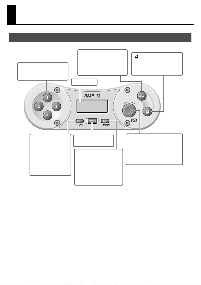
Memory Buttons [1]–[4]
These call up the sound sets
registered at memory locations 1–4.
[COACH] Button
This selects Coach mode.
Pressing this button twice in
succession will access the tap
tempo screen.
Display
[ (metronome)] Button
This starts or stops the metronome.
Also, this button is pressed to start
Coach mode.
[INST] Button
Use this to select the pad’s
sounds, or to make sound
settings.
By holding down this button
for a while (approximately
two seconds), you can enter
Live mode.
[POWER] Button
This turns the power on/off.
[BEAT] Button
Use this to make metronome
settings.
By holding down this button for a
while (approximately two
seconds), you can access the
System Setting screen.
Select Knob
This sets the tempo.
To edit a setting, turn the knob to
change the parameter or value, and
then press the knob to finalize the
parameter or value.
8
Page 9
Indications in the Display
fig.Display.eps
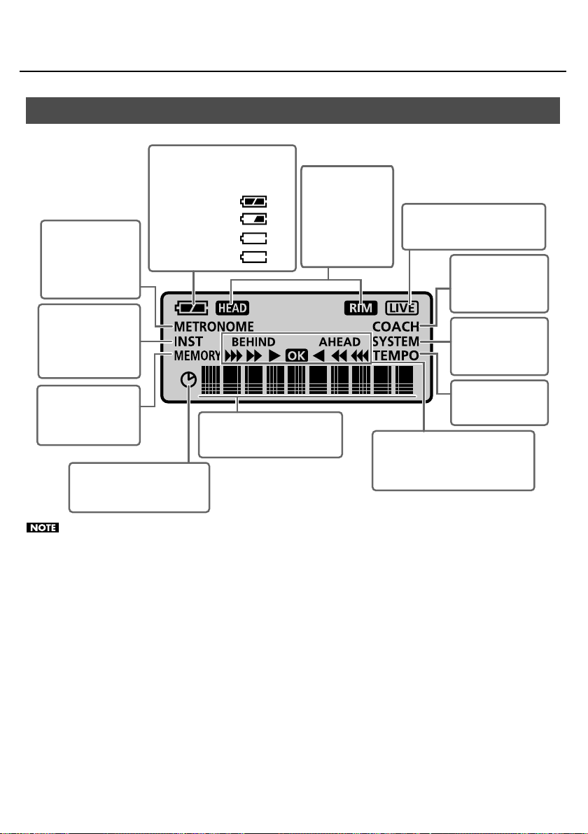
Battery Indicator
This indicates the remaining battery
power in four levels.
OK
METRONOME Icon
This will light or blink
when a metronome-
related parameter is
displayed.
INST Icon
This will light or blink
when a sound
(instrument) related
parameter is displayed.
MEMORY Icon
This will light when a
memory number is
displayed.
Timer Icon
This will light when the elapsed
time is displayed.
Approximately half
Little remaining
Replace the batteries. (blink)
Sound names, parameter names,
and parameter values are shown
here.
HEAD/RIM Icons
The HEAD icon will
light when you
strike the head, and
the RIM icon will
light when you
strike the rim.
Panel Descriptions
LIVE Icon
This will light when the RMP-12 is
in Live mode.
COACH Icon
This will light or blink
when the RMP-12 is in
Coach mode.
SYSTEM Icon
This will light or blink
when you’re making
system settings.
TEMPO Icon
This will light when the
tempo is displayed.
Time Check Indicator
This will appear when you’re using the
metronome or when the RMP-12 is in
Coach mode.
The battery indicator is an approximation. When the remaining battery power runs low, the audio quality may be affected or
operation may become unstable. Please replace the batteries as soon as possible.
9
Page 10
Panel Descriptions
Side Panel
fig.Connect.eps
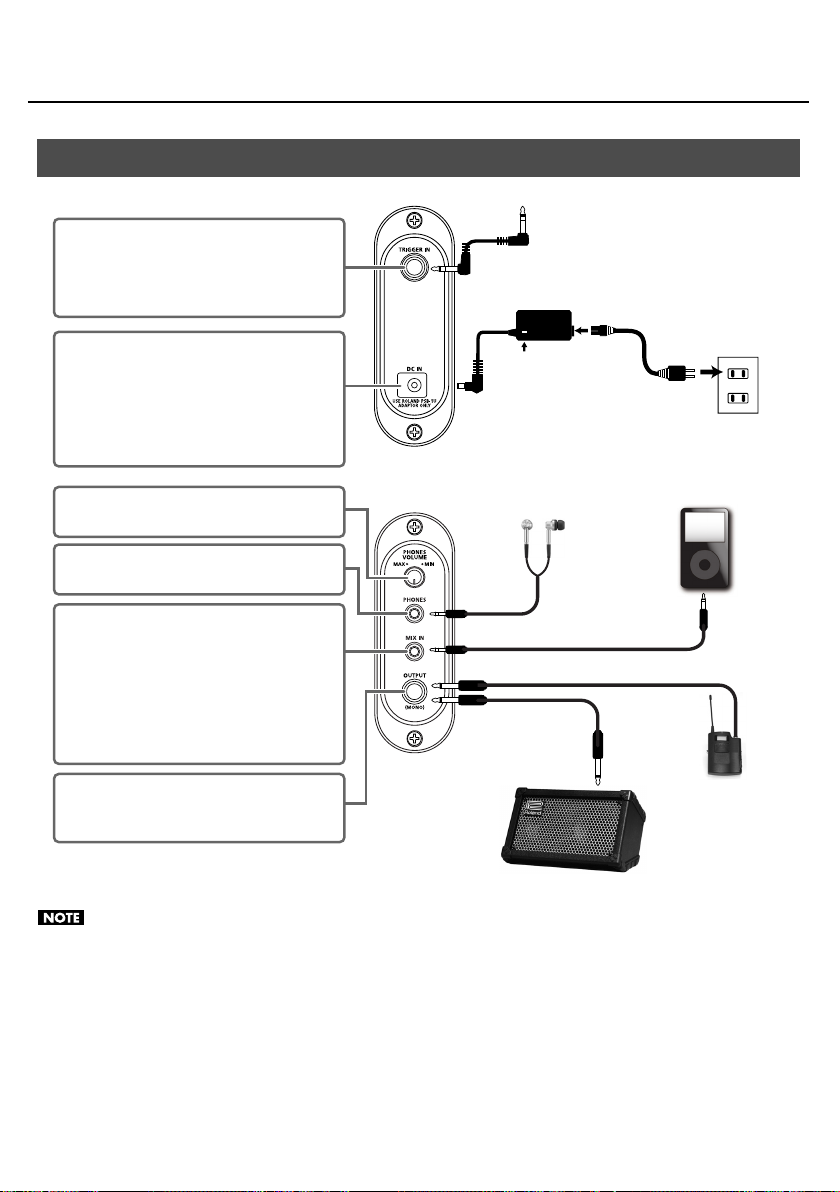
TRIGGER IN Jack
Use the included cable to connect the pad here.
* This cable is connected when the RMP-12 is
shipped from the factory.
to the TRIGGER OUT jack of the pad
AC adaptor
(sold separately)
DC IN Jack
You can connect an AC adaptor (ROLAND PSB-
series; sold separately) here.
If you use an AC adaptor, you’ll be able to perform
for an extended period of time without worrying
about the batteries running down.
[PHONES VOLUME] Knob
This adjusts the volume of the headphones.
PHONES Jack (stereo)
Connect your headphones here.
MIX IN Jack (stereo)
If you connect a portable audio player or other
audio source here, you’ll be able to practice along
with the music. The sound from this jack will be
output to the headphone jack.
* The sound received at the MIX IN jack is not
output from the OUTPUT jack.
OUTPUT (MONO) Jack
Connect this to your external amp or wireless
transmitter.
Indicator
Power Cord
Headphones
Monitor Amplifier, etc.
to Power outlet
Portable audio player,
etc.
Wireless transmitter,
etc.
• If you use an AC adaptor, use only the specified model (PSB-series).
• When connection cables with resistors are used, the volume level of equipment connected to the input (MIX IN jack) may be low. If
this happens, use connection cables that do not contain resistors.
• The RMP-12’s output is monaural.
• Do not use a conversion adaptor plug. The weight of the plug may cause it to fall out of the jack during performance.
• To prevent malfunction and/or damage to speakers or other devices, always turn down the volume, and turn off the power on all
devices before making any connections.
10
Page 11
Getting Ready to Play
• Avoid outdoor use (practice) in rainy conditions. Such
use will cause malfunctions.
• Take care that dirt or other foreign matter does not
enter the inside of the unit from the underside of the
pad. Such foreign matter will cause faulty operation or
malfunctions.
• Do not insert your hand or fingers from the rear of the
pad. Doing so may cause injury to you, or may cause
the unit to malfunction.
Check the Connections between the Sound Module And the Pad
fig.triggerin.eps
TRIGGER OUT
jack
TRIGGER IN
jack
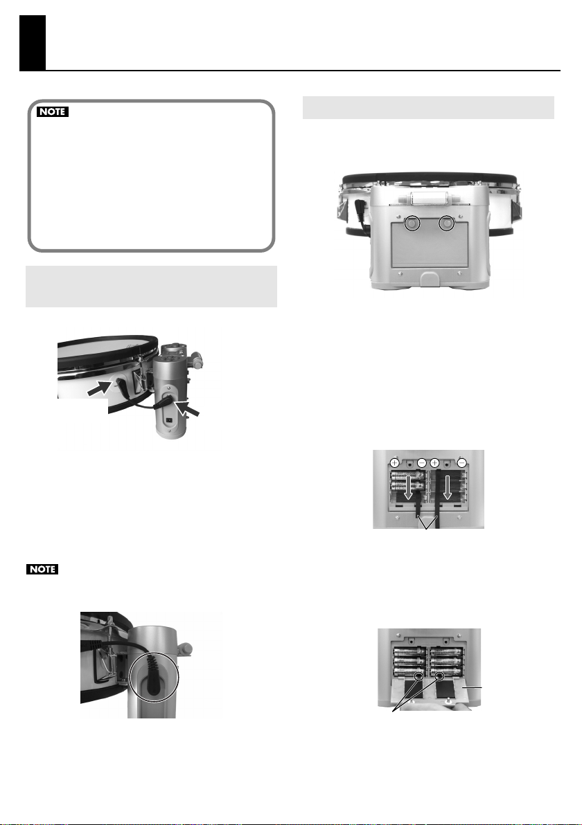
Install the Batteries
1.
Loosen the two screws that fasten the cover of the
battery compartment, and remove the cover.
2.
Install the supplied batteries into the battery
compartment, while carefully observing the
correct polarity (+/- orientation).
Insert the batteries from above the battery ties. Make sure
that the ends of the battery ties are not hidden below the
batteries.
As shown in the illustration, insert the batteries in order,
beginning at the top. You should insert the “+” end of each
battery first.
Make sure that the cable that connects the
1.
TRIGGER IN jack on the sound module’s side panel
to the TRIGGER OUT jack of the pad is connected
securely at both ends.
This cable is connected when the RMP-12 is shipped from
the factory.
Make sure that the plug is NOT in the position shown in
the photo below.
Battery ties
Firmly close the cover of the battery compartment,
3.
and fasten it using the screws you removed in step 1.
Be careful not to pinch the battery ties when you close the
battery cover.
Battery cover
Battery ties
11
Page 12

Getting Ready to Play
Removing the Batteries
To remove the batteries, switch off the RMP-12’s power, detach
the battery cover, and pull the end of the battery tie to remove
the batteries.
The batteries may fly out if you pull too strongly on a
battery tie. Use caution when removing the batteries.
Battery Lifespan
When the batteries run down, the battery indicator in the upper
left of the screen will blink. The power will turn off five seconds
after the “Batt Low!” indication appears. Please replace the
batteries as soon as possible.
• The reading of the battery indicator is an
approximation.
• When replacing the batteries, use AA alkaline batteries
(six batteries).
• Do not mix new and old batteries.
• When using alkaline batteries, their lifespan for
continuous operation at room temperature will be
approximately 8 hours. (This will vary depending on the
conditions of use.)
• Remove the batteries whenever the unit is to remain
unused for an extended period of time.
Connecting the AC Adaptor (Sold Separately)
A ROLAND PSB-series AC adaptor (sold separately) can be used to
power the RMP-12.
1.
Make sure that the power for the RMP-12 is
switched off.
2.
Connect the power cord to the AC adaptor.
3.
Connect the AC adaptor to the RMP-12’s DC IN
jack, and plug the power cord into an AC outlet.
fig.ACadaptor.eps
AC Adaptor
Power Cord
to AC Outlet
Indicator
Place the AC adaptor so the side with the indicator (see
illustration) faces upwards and the side with textual
information faces downwards. The indicator will light
when you plug the AC adaptor into an AC outlet.
Use only the ROLAND PSB-series AC adaptor. Other
adaptors may cause malfunction or damage to the
RMP-12 and must never be used.
12
Page 13

Getting Ready to Play
Adjusting the Head Tension
Before you begin playing, use the included drum key to adjust
the head tension for the desired strike response. The head is NOT
tuned before shipping.
Always tighten the tuning bolts in the order shown in the figure.
fig.TuningBolt.eps
24
65
3
If the head is tensioned too tightly, you won’t be able
to use the RMP-12’s performance functions correctly.
To learn more about tensioning the head, please watch
the included “Application Guide DVD” in conjunction
with this manual.
Failure to adjust the tension may result in damage to
the head.
Head tension may change with extended use. Make
adjustments as needed.
1
Attaching the RMP-12 to a Commercially Available Snare Stand
Caution when attaching the RMP-12 to a
• If you use a commercially available snare stand designed for
• Make sure to fully spread the legs of the stand.
• Place the RMP-12 so that its sound module is above one of
• Take care that the fasteners of the stand do not pinch the
• The RMP-12 is heavier on the side where the sound module
commercially available snare stand
performing while standing, choose a model that is able to
securely accommodate a 12-inch diameter snare.
the legs of the stand.
cable that connects the RMP-12’s pad and sound module.
is located. Take care not to drop the RMP-12 when placing it
on the stand.
Place the RMP-12 so that
its sound module is above
one of the legs of the stand
If you won't be using the RMP-12 for an extended
period of time, please loosen the head tension.
Using the Cable Tie
The cable that connects other equipment to the RMP-12 can be
fastened to the stand using the included cable tie; this will make
it less likely that the cable can be pulled out accidentally.
Allowing some slack in the cable, fasten it to the
1.
stand using the cable tie.
Leave some
slack in the
cables
Wind the
cable tie
once
Tighten it
not to slip
Turn back to
fix the cables
13
Page 14

Getting Ready to Play
Attaching the RMP-12 to a Marching Carrier (Sold Separately)
Caution when attaching the RMP-12 to a marching carrier
• If you want to attach the RMP-12 to a marching snare carrier,
use the specified model (sold separately:
RMP12
).
• Do not put your fingers
between the RMP-12 and
OP-RMP12. Your fingers
could get pinched, causing
injury.
Before replacing the
batteries, you must either
take off the marching carrier
or detach the RMP-12 from
the marching carrier.
• When placing the marching carrier on a floor or other
surface when the RMP-12 is attached, be careful not to
subject it to physical impact.
It may be damaged if you set it down roughly.
If you place the marching carrier on a floor or other surface,
you should fold it as shown in the photo.
fig.4j
Roland OP-
About the Attachable Marching Carrier
fig.1j
• J-rod type marching carrier for
snare
• Dimensions of appropriate J-rod
fig.1j
* In some cases, it will not be
14.0–14.3 mm
Diameter:
Length of portion “A”: 40mm or
greater
possible to attach a J-rod type
marching carrier even if it has
the above dimensions.
40mm
or greater
J-rod
A
About the Tilt Feature
It is possible to fold the RPM-12 upward as shown in
illustration.
fig.4j
fig.4j
• If you want to play the RMP-
12 while it’s attached to a
snare stand, you must
remove the OP-RMP12.
If you leave the OP-RMP12
attached, you may
experience noise during
performance, and you also
risk dropping the unit.
14
* The locks must be engaged when you fold the RMP-12
upward. If the locks are not engaged, the RMP-12 may
detach from the marching carrier, possibly causing
malfunction or injury.
* To avoid getting your fingers pinched when moving the
RMP-12 from the folded-up position to the normal playing
position, make sure to place both of your hands on the RMP-
12’s pad while you lower the unit.
Page 15

Attachment
1.
Using the drum key included with the RMP-12 or a
commercially available drum key, loosen the
screws (A, two locations) by approximately 10 mm.
fig.1j
A
10mm
* Avoid placing fingers inside the holes in which the J-rods are
inserted.
2.
Loosen the screws (B, two locations) that hold the
J-rods of the marching carrier in place—just
enough to make it possible to move the J-rods.
* Do not remove the screws (B) that hold the J-rods in place.
fig.2j
Getting Ready to Play
4.
Adjust the J-rods so that the OP-RMP12 is
horizontal and parallel.
fig.4j
Parallel
Fasten the J-rods by tightening the screws you
5.
loosened in step 2.
fig.j
6.
While making sure that the J-rods are inserted all
the way, securely tighten the screws on the OPRMP-12 that hold the J-rods in place.
fig.4j
A
B
Insert the OP-RMP12 into the J-rods.
3.
Insert it all the way, with the front and back oriented as
shown in illustrations.
fig.4j
* If the J-rods are not inserted all the way into the OP-RMP12,
the OP-RMP12 cannot be fastened securely, causing the risk
that it may come off of the J-rods while you perform.
Put the marching carrier onto your body.
7.
Turn the lock levers (C, two locations) so they're
8.
unlocked.
fig.j
C
Locked
Unlocked
15
Page 16

Getting Ready to Play
9.
Attach the RMP-12 and lock it in place.
fig.j
* You must lock them when the RMP-12 is mounted. If they
are not locked, the RMP-12 may detach from the marching
carrier during performance, possibly causing malfunction or
injury.
fig.j
10.
Adjust the marching carrier to adjust the height of
the RMP-12’s pad.
Using the Cable Tie
If you use the RMP-12 with an audio cable connected to its
OUTPUT jack, use the included cable tie to secure the cable.
If you use a cable tie, you’ll be able to perform without being
obstructed by the cable. The cable tie provides the additional
benefit of preventing the cable from being pulled out even if you
accidently step on it.
1.
Fasten the cable tie around the cable.
fig.4j
2.
Attach the cable tie to the J-rod.
Example 1
fig.4j
11.
Turn the angle adjustment screw (D) to adjust the
angle of the RMP-12’s pad
fig.4j
D
fig.4j
16
Example 2
fig.4j
Page 17

Getting Ready to Play
Turning the Power On and Off
Once the connections have been completed, turn on
power to your audio devices in the order specified.
Turning on devices in the wrong order may cause
malfunction and/or damage to speakers and other devices.
Turn the [PHONES VOLUME] knob to the minimum
1.
level.
2.
Switch on the power to the device that’s
connected to the MIX IN jack.
3.
Press the [POWER] button to turn on the power.
Always make sure to have the volume level turned
down before switching on power. Even with the
volume all the way down, you may still hear some
sound when the power is switched on, but this is
normal, and does not indicate a malfunction.
This unit is equipped with a protection circuit. A brief
interval (a few seconds) after power up is required
before the unit will operate normally.
While striking the head, gradually turn the [PHONES
4.
VOLUME] knob to adjust the volume level.
If an Amp is Connected to the OUTPUT Jack
Turn down the volume control on each of the
1.
devices in your system.
2.
Switch on the power to the device that’s
connected to the MIX IN jack.
Press the [POWER] button to turn on the power.
3.
4.
Turn on the connected amp system, and adjust the
volume to the desired level.
When Turning Off the Power
Before switching off the power, lower the volume on each of the
devices in your system and then turn off the devices in the
reverse order to which they were switched on.
Auto Power-off
To prevent the batteries from running down unnecessarily, the
Auto Power-off function will automatically turn off the power if
the pad has not been struck or any other operation performed for
ten minutes after the most recent button operation.
If the metronome is on, the power will automatically turn off if the
pad has not been struck or any other operation performed for
twenty minutes after the most recent button operation.
The Auto Power-off function will not operate in Live mode (p. 28).
17
Page 18

Selecting Sounds
Selecting Sounds (Memory Buttons)
A set of two sounds is assigned to each memory button [1]–[4]:
one sound played by the head and another sound played by the
rim.
1.
Press one of the [1]–[4] buttons.
The name of the sound set assigned to the selected button
will be displayed for approximately two seconds.
Then, the metronome tempo will be displayed.
Memory Number
2.
Strike the pad.
Striking the head and rim will produce different sounds.
If you strike the head and rim simultaneously, only one
of the sounds will be heard. It is not possible to play
both sounds simultaneously.
Factory settings
Sound Set Name Pad Instrument
Button
1 MarchSD
BD&Cym
2
3
4
Taiko
SFX
If you want to change the sound set assigned to the
memory button, or to edit settings such as tuning and
volume, refer to “Changing the Settings of the Memory
Buttons” (p. 25).
Head
Rim 2: mSD 1r
Head
Rim 58: Cym 1
Head
Rim 51: Taiko1r
Head
Rim 127: PhilHit
18
1: mSD 1
23: mBD 2
50: Taiko1
121: Scrtch3
Page 19

Practicing
Using the Metronome
Press the [ (metronome)] button.
1.
The metronome will sound.
The time check indicator will appear.
The timer icon will appear, allowing you to view the elapsed
time.
Elapsed time
2.
Use the select knob to set the tempo (20–300).
3.
The time check indicator will respond when you
strike the pad.
To stop the metronome, press the [
4.
(metronome)] button once again.
Time Check Indicator
The time check indicator will appear when you sound the
metronome.
The timing of your strikes will be analyzed to determine
whether they match the beat, and the result will be shown in
the time check indicator.
This helps you practice playing in accurate time while you
play along with the metronome.
You’re dragging.
You’re in perfect time.
You’re rushing.
19
Page 20

Practicing
Changing the Metronome Settings
1.
Press the [BEAT] button.
The METRONOME icon will blink in the display.
Turn the select knob to choose the parameter that
2.
you want to edit, and then press the select knob.
4.
When you’ve finished editing, turn the select knob
to choose “[OK],” and then press the select knob.
If you decide to discard your changes, turn the select knob
to choose “[CANCEL]” and then press the select knob.
You will exit the editing screen.
As an alternative to selecting “[OK]” in step 4, you can
press the [BEAT] button or one of the [1]–[4] buttons to
change the settings and exit the metronome setting
screen.
Parameter Value
The value of the parameter you’re editing will blink.
Parameter
Beat
Rhythm
Volume
Sound
Grade
LineOut
Value Explanation
Specifies the time signature of the
0–13
0–10
1–7
EASY, HARD
ON, OF
metronome. If you choose “0,” no accent will be applied.
Specifies how the metronome will
sound.
Whole note
Quarter note
Eighth note
Triplet
Sixteenth note
Adjusts the volume of the metronome.
Changes the sound of the metronome.
1: ELECTRONIC
2: SWEEP
3: STICKS
4: BEEP
5: PULSE
6: COWBELL
7: SHAKER
Specifies whether the Time Check indicator will evaluate your playing leniently (EASY) or strictly (HARD).
Specifies whether the metronome
sound will be sent from the OUTPUT
jack (ON) or not sent (OF).
The changes you've made will be lost if you turn off the
power without exiting the setting screen.
3.
Turn the select knob to edit the value, and then
press the select knob.
If there are only two values, you can press the select knob to
toggle between the two values.
20
Page 21

Practicing
Practicing with Coach Mode
Press the [COACH] button.
1.
The RMP-12 will enter Coach mode.
A menu name will appear.
Turn the select knob to select the desired menu.
2.
Menu
Menu name Explanation Page
TimeScore
Speed
Check
Rhythm
Note
Up/Down
Dyna
Meter
TapTempo
Time Check
Score
Speed Check
Rhythmic
Notes
Auto Up/
Down
Dyna Meter
Tap Tempo
Practice playing with accurate timing. Your accuracy
will be scored numerically.
Practice playing with accurate timing. The tempo will
increase as you continue
playing accurately.
Practice continuing to play
while the note length
changes.
Practice continuing to play
while the tempo increases
or decreases.
Visually confirm the force of
your strikes.
The metronome tempo will
be determined by the interval at which you strike the
pad.
* When you’re not in
Coach mode, you can
also access the Tap
Tempo screen by
pressing the [COACH]
button twice in
succession.
p. 22
p. 22
p. 23
p. 23
p. 24
p. 24
Editing the Menu Settings
1.
Press the [COACH] button.
The RMP-12 will enter Coach mode.
A menu name will appear.
2.
Turn the select knob to select the desired menu,
and then press the select knob.
3.
Turn the select knob to choose the parameter you
want to edit, and then press the select knob.
Parameter Value
For an explanation of the parameters, refer to the reference
page for each menu.
4.
Turn the select knob to choose the desired value,
and then press the select knob.
If there are only two values, you can press the select knob to
toggle between the two values.
When you’ve finished making settings, turn the
5.
select knob to choose “[START]” and then press
the select knob to start the menu.
At this time, you can return to the menu name screen by
turning the select knob to choose “[BACK]” and pressing the
select knob.
You can start by pressing the [ (metronome)]
button.
3.
Press the [ (metronome)] button to start the
menu.
The way in which the menu ends will depend on the menu.
Refer to the page that explains each menu.
4.
To exit Coach mode, press the [COACH] button.
You can use the memory buttons to switch sounds
even while you’re practicing in Coach mode.
The tempo you specify while in a menu will be the
tempo of the metronome after you exit Coach mode.
21
Page 22

Practicing
Checking Your Timing Accuracy as a Numerical Score (TimeScore: Time Check Score)
This function lets you practice your accuracy while listening to
the metronome.
The screen will indicate a numeric score according to how well
your pad strikes match the beat.
You can make the following settings.
Parameter
Grade
Meas
Tempo
As an alternative to pressing the [ (metronome)] button, you
can also start by turning the select knob to choose “[START].”
How to practice
When you start, there will be a two-measure count-in.
After the count-in, strike the pad in time with the
metronome.
You can turn the select knob to change the tempo even
while you practice.
When you’re finished practicing
When you reach the specified measure, practice will end,
and the score will be displayed.
Press the select knob to return to the menu name screen.
To start practice once again, press the [ (metronome)]
button instead of the select knob.
When you’re finished practicing, press the
[ (metronome)] button to stop the metronome and
return to the menu name screen.
Value Explanation
Specifies whether the Time Check indicator
EASY, HARD
8, 16, 32, 64
20–300
will evaluate your playing leniently (EASY) or
strictly (HARD).
Specifies the number of measures to be
evaluated.
Specifies the tempo at which you will practice.
Checking Your Timing Accuracy as the Tempo Gradually Rises (SpeedCheck)
This function lets you practice your accuracy while listening to
the metronome.
When you are able to play accurately, the tempo will increase
automatically.
You can make the following settings.
Parameter
Grade
Meas
Tempo
As an alternative to pressing the [ (metronome)] button, you
can also start by turning the select knob to choose “[START].”
How to practice
When you start, there will be a two-measure count-in.
After the count-in, strike the pad in time with the
metronome.
If you are able to play accurately for the specified number of
measures, the display will indicate “Good.” If only a few hits
were accurate, the display will indicate “Again.” If the “Good”
indication appears, the tempo will increase. If “Again”
appears, practice again at the same tempo.
When you’re finished practicing
When you’re finished practicing, press the
[ (metronome)] button to stop the metronome and
return to the menu name screen.
Value Explanation
Specifies whether the Time Check indicator
EASY, HARD
8, 16, 32, 64
20–300
will evaluate your playing leniently (EASY) or
strictly (HARD).
Specifies the number of measures to be
evaluated.
Specifies the tempo at which you will begin
practicing.
22
Page 23

Practicing
Practicing Change-ups (RhythmNote)
This function lets you practice playing while you change the
length of the notes. This is an effective way to practice changeups, or to improve your feel for note lengths.
The metronome’s rhythm type will change every two measures;
strike the pads in time with the sounds. You’ll start with half
notes, the note value will gradually become shorter, and then
you’ll return to half notes and continue repeating.
You can make the following settings.
Parameter
Type
Tempo
Value
20–300
Start
Start
Start
Start
Specifies the tempo at which you will practice.
As an alternative to pressing the [ (metronome)] button, you
can also start by turning the select knob to choose “[START].”
How to practice
When you start, the timer will start and there will be a two-
measure count-in.
After the count-in, strike the pad in time with the
metronome.
During the practice, the elapsed time will be displayed.
Even while practicing, you can change the tempo by turning
the select knob.
Explanation
Improving Your Tempo Control and Endurance (UP/DOWN)
This function lets you practice while the tempo gets faster and
slower. Raising and lowering the tempo will improve your
endurance.
The metronome’s value will start from the minimum value and
increase in steps of one. When it reaches the maximum value, it
will decrease to the minimum value in steps of one. This will
continue repeating.
You can make the following settings.
Parameter
Rate
Min
Max
As an alternative to pressing the [ (metronome)] button, you
can also start by turning the select knob to choose “[START].”
How to practice
When you start, the timer will start. Strike the pad in time
with the metronome.
If the specified “Max” value was too high, press the select
knob when you reach the fastest tempo you can play. The
maximum tempo will be reset to the tempo at the time you
pressed the select knob.
During practice, the elapsed time will be displayed.
When you’re finished practicing
When you’re finished practicing, press the [ (metronome)]
button to stop the metronome and return to the menu
name screen.
Value Explanation
Higher values will cause a faster tempo
1–5
20–300
21–300
change. With the “5” setting, the tempo will
change each beat.
Specifies the minimum tempo value.
* The tempo you specify here will be the
tempo of the metronome after you exit
Coach mode.
Specifies the maximum tempo value.
When you’re finished practicing
When you’re finished practicing, press the
[ (metronome)] button to stop the metronome and
return to the menu name screen.
23
Page 24

Practicing
Checking Your Dynamics and Timing Simultaneously (DynaMeter)
This function lets you view the force of your strikes as you
practice. This method of practicing is an effective way to make
the volume more consistent between your right hand and left
hand, and to improve the smoothness of your overall sound.
You can make the following settings.
Parameter
Tempo
As an alternative to pressing the [ (metronome)] button, you
can also start by turning the select knob to choose “[START].”
How to practice
When you start, the timer will start. Strike the pad in time
with the metronome.
During the practice, the elapsed time will be displayed each
minute.
Even while practicing, you can change the tempo by turning
the select knob.
Value Explanation
20–300
Weak Strong
Specifies the tempo at which you will practice.
Meter Tempo
Setting the Tempo by the Strike Interval (TapTempo)
You can also access the tap tempo screen by pressing
the [COACH] button twice in succession when you’re
not in Coach mode.
This sets the metronome tempo (20–300) by the interval at which
you strike the pad. For example, you can set the metronome
tempo by striking the pad in time with the song you want to play.
The tempo you specify here will still be valid when you exit Coach
mode.
If you press the [ (metronome)] button or the select knob to
start the menu.
The display will indicate “Tap:” and the value will blink.
To change the value, strike the pad in quarter-note intervals of
the desired tempo. You can also change the value by turning the
select knob.
When you’ve specified the tempo, press the select knob to
finalize the value and refer to the menu name screen.
When you’re finished practicing
When you’re finished practicing, press the
[ (metronome)] button to stop the metronome and
return to the menu name screen.
The indication will be stronger if you strike near the
center of the pad.
If you use a sound for which the tuning (p. 25) is set to
“DYNA1” or “DYNA2,” your striking force will be
reflected by the sound as well as shown in the Dyna
Meter, thus letting you practice more effectively.
24
Page 25

Changing the Settings of the Memory Buttons
A sound set together with settings such as tuning and volume
can be registered to each memory button.
Press one of the [1]–[4] buttons to select the
1.
memory location whose settings you want to
change.
Press the [INST] button.
2.
The INST icon in the display will blink.
3.
Turn the select knob to select the parameter that
you want to edit, and then press the select knob.
Parameter Value
The value of the chosen parameter will blink.
Parameter
(sound
name)
Tune
Volume
[Name…]
4.
If you want to change the sound, tuning, or
Value Explanation
1–128,
129 (OFF)
-600–+600
(cent)
DYNA1,
DYNA2
0–100
Renames the setting.
The name you assign here is shown when you press
the currently selected memory button (maximum of
seven characters)
For details, refer to “Naming a Sound Set.”
Refer to the “Sound list.” If you
choose “129,” there will be no sound
when you strike the pad.
Adjusts the tuning of the head or
rim.
The pitch will change according to
the force of your strike (
The pitch will rise for strong strikes,
and fall for weak strikes.
“DYNA1” will change the pitch
smoothly according to the force of
your strike.
“DYNA2” will change the pitch in
semitone steps according to the
force of your strike.
Adjusts the volume of the head or
rim.
Dyna Pitch
volume, strike the head or the rim to specify which
you want to change.
An icon (HEAD or RIM) will light to indicate whether you’re
editing the head or rim.
6.
When you’ve finished editing, turn the select knob
to select “OK,” and then press the select knob.
If you decide to cancel the settings, turn the select knob to
select “[CANCEL],” and then press the select knob.
You will exit the editing screen.
As an alternative to selecting “[OK]” in step 6, you can
press the [INST] button or one of the [1]–[4] buttons to
change the settings and exit the editing screen.
The changes you’ve made will be lost if you turn off the
power without exiting the editing screen.
Naming a Sound Set
Press one of the [1]–[4] buttons to select the
1.
memory that you want to edit.
Press the [INST] button.
2.
Turn the select knob to choose “[Name…],” and
3.
then press the select knob.
).
4.
Turn the select knob to select a character at the
blinking cursor location, and then press the select
knob.
When you press the select knob, the cursor will move one
space to the right.
You can assign a name of up to seven characters to the
sound set.
When the cursor is located at the seventh
5.
character, pressing the select knob will take you
back to the previous screen.
Press the [INST] button once again.
6.
You will exit the editing screen.
The changes you’ve made will be lost if you turn off the
power without exiting the editing screen.
Cursor
Turn the select knob to edit the value, and then
5.
press the select knob.
25
Page 26

Changing the Settings of the Memory Buttons
Sound List
No.
Display Name
1
mSD 1
2
mSD 1r
3
mSD 2
4
mSD 2r
5
mSD 3
6
mSD 3r
7
mSD 4
8
mSD 4r
9
mSD 5
10
mSD 5r
11
SD 1
12
SD 1r
13
SD 2
14
SD 2r
15
OrchSD
16
eSD
17
808SD
18
909SD
19
Xstick1
20
Xstick2
21
mBD 1
22
mBD 1r
23
mBD 2
24
mBD 2r
25
mBD 3
26
mBD 3r
27
mBD 4
28
mBD 4r
29
BD 1
30
BD 2
31
BD 3
32
BD 4
33
OrchBD
34
eBD 1
35
eBD 2
36
eBD 3
37
808BD
38
909BD
39
mTom 1
40
mTom 2
41
mTom 3
42
mTom 4
Marching Snare Drum 14"x12"
Marching Snare Drum 14"x12" Rim
Double Snare Drum 13"x11"
Double Snare Drum 13"x11" Rim
Short Snare Drum 14"x10"
Short Snare Drum 14"x10" Rim
Pipe Snare Drum 14"x12"
Pipe Snare Drum 14"x12" Rim
Parade Snare Drum 14"x12"
Parade Snare Drum 14"x12" Rim
Snare Drum 1
Snare Drum 1 Rim
Snare Drum 2
Snare Drum 2 Rim
Orchestral Snare Drum
Electronic Snare Drum
TR-808 Snare Drum
TR-909 Snare Drum
Cross Sticks 1
Cross Sticks 2
Marching Bass Drum 16"
Marching Bass Drum 16" Rim
Marching Bass Drum 20"
Marching Bass Drum 20" Rim
Marching Bass Drum 24"
Marching Bass Drum 24" Rim
Marching Bass Drum 28"
Marching Bass Drum 28" Rim
Bass Drum 1
Bass Drum 2
Bass Drum 3
Bass Drum 4
Orchestral Bass Drum
Electronic Bass Drum 1
Electronic Bass Drum 2
Electronic Bass Drum 3
TR-808 Bass Drum
TR-909 Bass Drum
Marching Quad Tom 6"
Marching Quad Tom 10"
Marching Quad Tom 12"
Marching Quad Tom 13"
Display Name
No.
43
mTom 5
44
808Tom1
45
808Tom2
46
808Tom3
47
eTom 1
48
eTom 2
49
eTom 3
50
Taiko1
51
Taiko1r
52
Taiko2
53
Taiko2r
54
TimpniC
55
TimpniG
56
TubBelC
57
TubBelG
58
Cym 1
59
Cym 1mt
60
Cym 2
61
Cym 3
62
Cym 4
63
Cym 5
64
Cym 6
65
RideCym
66
HH cl
67
HH op
68
808HHcl
69
808HHop
70
Claves
71
Tambrin
72
Tri op
73
Tri mt
74
Shaker
75
Cowbel1
76
Cowbel2
77
BlockH
78
BlockL
79
Ratchet
80
VibSlap
81
FlxTone
82
Crotale
83
ChnChng
84
Gong
85
WtrPhon
86
AccCym
87
XCym
Marching Quad Tom 14"
TR-808 Tom 1
TR-808 Tom 2
TR-808 Tom 3
Electronic Tom 1
Electronic Tom 2
Electronic Tom 3
Nagado Taiko
Nagado Taiko Rim
Hira Taiko
Hira Taiko Rim
Timpani C
Timpani G
Tublar Bell C
Tublar Bell G
Piatti Cymbals
Muted Piatti Cymbals
Crash Cymbal 13"
Thin Crash Cymbal 14"
Effect Cymbal 14"
Splash Cymbal 8"
China Cymbal 16"
Ride Cymbal 20"
Closed Hi-hat
Opened Hi-hat
Closed TR-808 Hi-hat
Opened TR-808 Hi-hat
Claves
Tambourine
Open Triangle
Muted Triangle
Shaker
Cowbell 1
Cowbell 2
Wood Block High
Wood Block Low
Ratchet
Vibra-slap
Flex Metal
Crotale
Cheng Cheng
Gong
Water Phone
Accent Cymbal
Cross Cymbal
26
Page 27

Display Name
No.
88
89
90
91
92
93
94
95
96
97
98
99
100
101
102
103
104
105
106
107
108
109
110
111
112
113
114
115
116
117
118
119
120
121
122
123
124
125
126
127
128
129
LayrCym
SleighB
BelTree
TrChime
TimbleH
TimbleL
CongaHi
CongaLo
BongoHi
BongoLo
Djembe
Tabla 1
Tabla 2
Tabla 3
Claps 1
Claps 2
Clap
FngSnap
Stomp
Hammer
FightBl
Sword
Gadgets
TypWtr1
TypWtr2
Clock
CarHorn
GlsCrsh
Bird
Thunder
Jet
Scrtch1
Scrtch2
Scrtch3
Laser
Verby
Byon
Trsform
SuperLo
PhilHit
PracPad
OFF
Layered Cymbal
Sleigh Bells
Bell Tree
Tree Chimes
Timbale High
Timbale Low
Conga High
Conga Low
Bongo High
Bongo Low
Djembe
Tabla Na
Tabla Tin
Tabla Tun
Hand Claps 1
Hand Claps 2
Hand Clap
Finger Snap
Stomp
Hammer
Fight Bell
Sword
Gadgets
Type Writer Key Click 1
Type Writer Key Click 2
Grandfather's Clock
Car Horn
Glass Crash
Bird
Thunder
Jet Plane
Scratch 1
Scratch 2
Scratch 3
Laser beam
Verby Stick
Byon
Transform
Super Low
Philly Hit
Practice Pad
Off
Changing the Settings of the Memory Buttons
27
Page 28

Performing in Live Mode
The RMP-12 provides a “Live mode” that lets you lock the function
of buttons that you would not use during a live performance, so
that the metronome will not start sounding even if you
inadvertently press a button.
Hold down the [INST] button for about two
1.
seconds.
The LIVE icon will light, and the RMP-12 will enter Live mode.
The display will indicate the number and name of the
currently selected memory button.
Muting the Sound of the Pad
You can prevent the pad from producing sound in Live mode
(Mute).
You can’t mute an already-playing sound.
Muting Only While You Press the Button
Press and hold down the select knob.
1.
The display will indicate “<MUTE>.”
Buttons that can be used in Live mode
• [1]–[4] buttons: Select sounds
• [POWER] button: Hold down (for approximately two
seconds) to turn off the power
* Live mode will be cancelled the next time you turn on
the power.
• Press the select knob: Mute function (see “Muting the
Sound of the Pad”)
Nothing will happen when you operate a button other than
those listed above, or turn the select knob.
To cancel Live mode, hold down the [INST] button
2.
(for approximately two seconds).
The LIVE icon will go dark.
The Auto Power-off function (p. 17) will not operate in
Live mode.
As long as you hold down the select knob, striking the pad
will not produce sound.
2.
To cancel muting, release the select knob.
Now the pad will produce sound when struck.
Keeping the Pad Muted
1.
While holding down the select knob, turn it
towards the “+” at least one third of a turn.
The display will blink <MUTE>.
Release the select knob.
Striking the pad will not produce sound.
To cancel muting, press the select knob.
2.
Now the pad will produce sound when struck.
28
Page 29

System Settings
How to Make System Settings
Settings that affect the entire RMP-12 are called “system settings.”
Hold down the [BEAT] button for a while.
1.
The SYSTEM icon will blink in the display.
2.
Turn the select knob to choose the parameter that
you want to edit, and then press the select knob.
Parameter Value
The value of the parameter you’re editing will blink.
For details, refer to the section that explains each parameter.
Parameter
LCDcont
LineVol
Sens
RimAdj
RimGain
Turn the select knob to edit the value, and then
3.
press the select knob.
When you’ve finished editing, turn the select knob
4.
to choose “[OK]” and then press the select knob.
If you decide to discard the changes you made, turn the
select knob to choose “[CANCEL]” and then press the select
knob.
You will exit the editing screen.
As an alternative to selecting “[OK]” in step 4, you can
confirm the change and exit the system setting screen
by pressing the [BEAT] button or a [1]–[4] button.
The changes you’ve made will be lost if you turn off the
power without exiting the editing screen.
Value Explanation
1–10
0–10
-5–+9
-9–+9
-9–+9
Adjusts the display’s contrast.
Adjusts the volume that is output
to the OUTPUT (MONO) jack.
Adjusts the sensitivity of the head.
Adjusts how easily the rim will
sound.
Adjusts the sensitivity of the rim.
Adjusting the Display’s Contrast
In step 2 of “How to make system settings,” choose “LCDcont.”
Specify a value of 1–10. Higher values will make the display
darker.
Adjusting the Volume of the OUTPUT Jack
In step 2 of “How to make system settings,” choose “LineVol.”
Specify a value of 0–10. Higher values will increase the volume
sent to the OUTPUT jack.
Adjusting the Head Sensitivity
In step 2 of “How to make system settings,” choose “Sens.”
This sets the sensitivity of the head, adjusting the way in which
your striking force affects the loudness of the sound.
Specify a value of -5–+9. Higher values will increase the
sensitivity, allowing loud volumes to be produced even when you
strike the pad softly. Lower values will decrease the sensitivity, so
that the volumes produced will be low even if you strike the pad
strongly.
Adjusting the Sensitivity of the Rim
In step 2 of “How to make system settings,” choose “RimAdj” or
“RimGain.”
RimAdj (Rim adjust)
This adjusts how easy it will be to play rim shots.
Specify a value from -9 to +9. If the rim sound is produced
inadvertently when you strike the head strongly, decreasing this
value will solve the problem. If this value is too low, it will be
difficult to sound the rim instrument.
RimGain (Rim gain)
This sets the rim sensitivity, adjusting the way in which your
striking force affects the loudness of the sound.
Specify a value from -9 to +9. Higher values will allow loud sounds
to be produced even when you strike the rim softly. Lower values
will produce softer sounds even if you strike the rim strongly.
If the “Sens,” “RimAdj,” and “RimGain” values are set too
high, the RMP-12’s sensor may respond to loud sounds
near the pad (such as a strong rim shot on an acoustic
drum), inadvertently causing sound to be produced.
29
Page 30

System Settings
Restoring the Factory Settings (Factory Reset)
This operation will return all of the RMP-12’s settings to their
factory-set condition.
If you execute Factory Reset, all the settings you’ve
changed will be lost.
1.
Hold down the [BEAT] button for a while.
The SYSTEM icon will blink in the display.
Turn the select knob to choose “[Reset...],” and
2.
then press the select knob.
The display will ask “Sure?”
3.
Turn the select knob to choose “[YES],” and then
press the select knob.
If you decide not to execute the factory reset, turn the select
knob to choose “[NO],” and then press the select knob.
Once the factory reset has been carried out, the display will
indicate “Completed!” and you will exit the setting screen.
30
Page 31

Appendix
If an Error Message Appears
This section lists the different error messages that may appear,
along with their meanings and measures to resolve the problems
described.
(Battery Low!)
Meaning
The batteries have run down.
(Memory Error!)
Meaning
It is possible that the RMP-12’s
internal memory is damaged.
(Wave Error!)
Meaning
There is a problem with the
internal system.
The RMP-12’s power will turn off in
five seconds.
Replace the batteries as soon as the
battery icon (p. 9) blinks.
When you press any button, a factory reset (p. 30) will be executed.
(Any changes you’ve made to the
settings will be lost.)
If this does not solve the problem,
please contact your dealer or a
Roland service center.
Please contact your dealer or a
Roland service center.
Action
Action
Action
Replacing the Head and Hoop Rubber
The head and hoop rubber are consumable items whose
performance will diminish with use over time. If the head surface
or the hoop rubber should become torn, or if there is slack in the
head surface even after you’ve adjusted the head tension, please
replace the head or hoop rubber.
To purchase a replacement head (MH-12 twelve-inch mesh head)
or to have the hoop rubber replaced, please contact your dealer
or a Roland customer service center.
Head
Replacing the Head
When replacing, use the included drum key.
Remove all tuning bolts.
1.
Gradually loosen each one in order, turning them
counterclockwise.
Do not lose the tuning bolts.
2.
Remove the old head.
3.
Place the new head in the case.
Hoop rubber
4.
Attach all six tuning bolts.
Adjust the tension of the head. Refer to “Adjusting the Head
Tension” (p. 13).
31
Page 32

Appendix
Specifications
RMP-12: Marching Percussion
Pad
Instruments
Instrument
Parameters
Memory Bank
Metronome
Rhythm Coach
Functions
Display
Connectors
Power Supply
Current Draw
Dimensions
Weight
Accessories
Options
Head Size
Trigger 2 (Head, Rim)
128
Tuning, Volume
4
Tempo
Beat 0–13
Rhythm Types 5 types
Click Sounds 7 types
Others Timer Function, Time Check Function
Time Check Score
Speed Check
Rhythmic Notes
Auto Up/Down
Dyna Meter
Tap Tempo
Custom Display
Phones Jack (Stereo miniature phone type)
Mix In Jack (Stereo miniature phone type)
Output Jack (1/4 inch phone type)
Trigger Input Jack (1/4 inch TRS phone type)
* This jack is connected to the pad with a cable when the RMP-12 is shipped from the factory.
AC Adaptor Jack
DC 9 V: Dry battery LR6 (AA) type (alkaline) x 6
or AC Adaptor (optional)
* Expected battery life under continuous use:
Alkaline: 8 hours
This figure will vary depending on the actual conditions of use.
220 mA
347.5 (W) x 416 (D) x 193.8 (H) mm
13-11/16 (W) x 16-7/16 (D) x 7-11/16 (H) inches
3.7 kg / 8 lbs 3 oz (including battery)
Owner’s Manual
Quick Guide
Application Guide DVD
Dry battery LR6 (AA) type (alkaline) x 6
Drum Key
Cable Tie
AC Adaptor: PSB-120/PSB-230EU/PSB-230UK/PSB-240A
Mesh Replacement Head: MH-12
Marching Carrier Attachment: OP-RMP12
12 inches
20–300
In the interest of product improvement, the specifications and/or appearance of this unit are subject to change without prior
notice.
32
Page 33

Index
Numerics
[1]–[4] buttons ................................................ 18
A
AC Adaptor....................................................... 12
Auto Power-off ............................................... 17
B
Batteries ............................................................ 11
Battery tie ......................................................... 11
Beat .................................................................... 20
[BEAT] button ................................... 20, 29–30
C
Cable Tie .................................................... 13, 16
[COACH] button ............................................. 21
Coach Mode .................................................... 21
D
DC IN jack ......................................................... 12
Display .................................................................. 9
Display’s Contrast ......................................... 29
Drum key .......................................................... 13
DynaMeter ....................................................... 24
Dyna Pitch ........................................................ 25
F
Factory Reset .................................................. 30
G
Grade ................................................................. 20
H
Head ........................................................... 18, 31
Head Tension .................................................. 13
Hoop Rubber .................................................. 31
I
[INST] button ............................................ 25, 28
L
LCDcont ........................................................... 29
LineOut ............................................................. 20
LineVol .............................................................. 29
Live Mode ........................................................ 28
M
Marching carrier ............................................ 14
Memory Buttons ..................................... 18, 25
Metronome ..................................................... 19
Sound ....................................................... 20
Time signature ....................................... 20
Volume ..................................................... 20
[Metronome] button ................................... 19
MUTE ................................................................. 28
Muting ............................................................... 28
N
Name... .............................................................. 25
O
OUTPUT Jack .................................................. 29
P
Power ................................................................ 17
[POWER] button ............................................. 17
Practicing ......................................................... 19
R
Rename ............................................................. 25
Rhythm .............................................................. 20
RhythmNote .................................................... 23
Rim ...................................................................... 18
RimAdj ............................................................... 29
RimGain ............................................................ 29
S
Sens .................................................................... 29
Sensitivity
Head .......................................................... 29
Rim ............................................................. 29
Side Panel ......................................................... 10
Snare Stand ..................................................... 13
Sound .................................................. 18, 20, 25
Volume ..................................................... 25
SpeedCheck .................................................... 22
System Settings ............................................. 29
T
Tap Tempo ....................................................... 24
Tempo ............................................................... 19
Tilt Feature ....................................................... 14
Time Check Indicator ................................... 19
TimeScore ........................................................ 22
Top Panel ............................................................. 8
TRIGGER IN jack .............................................. 11
TRIGGER OUT jack ......................................... 11
Tune ................................................................... 25
Tuning ............................................................... 25
Tuning bolts .................................................... 13
U
UP/DOWN ........................................................ 23
V
Volume ....................................................... 20, 25
OUTPUT jack ........................................... 29
33
Page 34

For EU Countries
For China
Page 35

Information
AFRICA
EGYPT
Al Fanny Trading Office
9, EBN Hagar Al Askalany
Street,
ARD E1 Golf, Heliopolis,
Cairo 11341, EGYPT
TEL: (022)-418-5531
REUNION
Maison FO - YAM Marcel
25 Rue Jules Hermann,
Chaudron - BP79 97 491
Ste Clotilde Cedex,
REUNION ISLAND
TEL: (0262) 218-429
SOUTH AFRICA
T.O.M.S. Sound & Music
(Pty)Ltd.
2 ASTRON ROAD DENVER
JOHANNESBURG ZA 2195,
SOUTH AFRICA
TEL: (011)417 3400
Paul Bothner(PTY)Ltd.
Royal Cape Park, Unit 24
Londonderry Road, Ottery 7800
Cape Town, SOUTH AFRICA
TEL: (021) 799 4900
ASIA
CHINA
Roland Shanghai Electronics
Co.,Ltd.
5F. No.1500 Pingliang Road
Shanghai 200090, CHINA
TEL: (021) 5580-0800
Roland Shanghai Electronics
Co.,Ltd.
(BEIJING OFFICE)
10F. No.18 3 Section Anhuaxili
Chaoyang District Beijing
100011 CHINA
TEL: (010) 6426-5050
HONG KONG
Tom Lee Music Co., Ltd.
Service Division
22-32 Pun Shan Street, Tsuen
Wan, New Territories,
HONG KONG
TEL: 2415 0911
Parsons Music Ltd.
8th Floor, Railway Plaza, 39
Chatham Road South, T.S.T,
Kowloon, HONG KONG
TEL: 2333 1863
INDIA
Rivera Digitec (India) Pvt. Ltd.
411, Nirman Kendra
Mahalaxmi Flats Compound
Off. Dr. Edwin Moses Road,
Mumbai-400011, INDIA
TEL: (022) 2493 9051
INDONESIA
PT Citra IntiRama
Jl. Cideng Timur No. 15J-15O
Jakarta Pusat
INDONESIA
TEL: (021) 6324170
KOREA
Cosmos Corporation
1461-9, Seocho-Dong,
Seocho Ku, Seoul, KOREA
TEL: (02) 3486-8855
MALAYSIA
Roland Asia Pacific Sdn. Bhd.
45-1, Block C2, Jalan PJU 1/39,
Dataran Prima, 47301 Petaling
Jaya, Selangor, MALAYSIA
TEL: (03) 7805-3263
VIET NAM
Suoi Nhac Company, Ltd
370 Cach Mang Thang Tam St.
Dist.3, Ho Chi Minh City,
VIET NAM
TEL: 9316540
When you need repair service, call your nearest Roland Service Center or authorized Roland
distributor in your country as shown below.
PHILIPPINES
G.A. Yupangco & Co. Inc.
339 Gil J. Puyat Avenue
Makati, Metro Manila 1200,
PHILIPPINES
TEL: (02) 899 9801
SINGAPORE
SWEE LEE MUSIC
COMPANY PTE. LTD.
150 Sims Drive,
SINGAPORE 387381
TEL: 6846-3676
TAIWAN
ROLAND TAIWAN
ENTERPRISE CO., LTD.
Room 5, 9fl. No. 112 Chung
Shan N.Road Sec.2, Taipei,
TAIWAN, R.O.C.
TEL: (02) 2561 3339
THAILAND
Theera Music Co. , Ltd.
100-108 Soi Verng
Nakornkasem, New
Road,Sumpantawongse,
Bangkok 10100 THAILAND
TEL: (02) 224-8821
AUSTRALIA/
NEW ZEALAND
AUSTRALIA/
NEW ZEALAND
Roland Corporation
Australia Pty.,Ltd.
38 Campbell Avenue
Dee Why West. NSW 2099
AUSTRALIA
For Australia
Tel: (02) 9982 8266
For New Zealand
Tel: (09) 3098 715
CENTRAL/LATIN
AMERICA
ARGENTINA
Instrumentos Musicales S.A.
Av.Santa Fe 2055
(1123) Buenos Aires
ARGENTINA
TEL: (011) 4508-2700
BARBADOS
A&B Music Supplies LTD
12 Webster Industrial Park
Wildey, St.Michael, Barbados
TEL: (246)430-1100
BRAZIL
Roland Brasil Ltda.
Rua San Jose, 780 Sala B
Parque Industrial San Jose
Cotia - Sao Paulo - SP, BRAZIL
TEL: (011) 4615 5666
CHILE
Comercial Fancy II S.A.
Rut.: 96.919.420-1
Nataniel Cox #739, 4th Floor
Santiago - Centro, CHILE
TEL: (02) 688-9540
COLOMBIA
Centro Musical Ltda.
Cra 43 B No 25 A 41 Bododega 9
Medellin, Colombia
TEL: (574)3812529
COSTA RICA
JUAN Bansbach Instrumentos
Musicales
Ave.1. Calle 11, Apartado
10237,
San Jose, COSTA RICA
TEL: 258-0211
CURACAO
Zeelandia Music Center Inc.
Orionweg 30
Curacao, Netherland Antilles
TEL:(305)5926866
DOMINICAN REPUBLIC
Instrumentos Fernando Giraldez
Calle Proyecto Central No.3
Ens.La Esperilla
Santo Domingo,
Dominican Republic
TEL:(809) 683 0305
ECUADOR
Mas Musika
Rumichaca 822 y Zaruma
Guayaquil - Ecuador
TEL:(593-4)2302364
EL SALVADOR
OMNI MUSIC
75 Avenida Norte y Final
Alameda Juan Pablo II,
Edificio No.4010 San Salvador,
EL SALVADOR
TEL: 262-0788
GUATEMALA
Casa Instrumental
Calzada Roosevelt 34-01,zona 11
Ciudad de Guatemala
Guatemala
TEL:(502) 599-2888
HONDURAS
Almacen Pajaro Azul S.A. de C.V.
BO.Paz Barahona
3 Ave.11 Calle S.O
San Pedro Sula, Honduras
TEL: (504) 553-2029
MARTINIQUE
Musique & Son
Z.I.Les Mangle
97232 Le Lamantin
Martinique F.W.I.
TEL: 596 596 426860
Gigamusic SARL
10 Rte De La Folie
97200 Fort De France
Martinique F.W.I.
TEL: 596 596 715222
MEXICO
Casa Veerkamp, s.a. de c.v.
Av. Toluca No. 323, Col. Olivar
de los Padres 01780 Mexico
D.F. MEXICO
TEL: (55) 5668-6699
NICARAGUA
Bansbach Instrumentos
Musicales Nicaragua
Altamira D'Este Calle Principal
de la Farmacia 5ta.Avenida
1 Cuadra al Lago.#503
Managua, Nicaragua
TEL: (505)277-2557
PANAMA
SUPRO MUNDIAL, S.A.
Boulevard Andrews, Albrook,
Panama City, REP. DE
PANAMA
TEL: 315-0101
PARAGUAY
Distribuidora De
Instrumentos Musicales
J.E. Olear y ESQ. Manduvira
Asuncion PARAGUAY
TEL: (595) 21 492147
PERU
Audionet
Distribuciones Musicales SAC
Juan Fanning 530
Miraflores
Lima - Peru
TEL: (511) 4461388
TRINIDAD
AMR Ltd
Ground Floor
Maritime Plaza
Barataria Trinidad W.I.
TEL: (868) 638 6385
URUGUAY
Todo Musica S.A.
Francisco Acuna de Figueroa
1771
C.P.: 11.800
Montevideo, URUGUAY
TEL: (02) 924-2335
VENEZUELA
Instrumentos Musicales
Allegro,C.A.
Av.las industrias edf.Guitar
import
#7 zona Industrial de Turumo
Caracas, Venezuela
TEL: (212) 244-1122
EUROPE
AUSTRIA
Roland Elektronische
Musikinstrumente HmbH.
Austrian Office
Eduard-Bodem-Gasse 8,
A-6020 Innsbruck, AUSTRIA
TEL: (0512) 26 44 260
BELGIUM/FRANCE/
HOLLAND/
LUXEMBOURG
Roland Central Europe N.V.
Houtstraat 3, B-2260, Oevel
(Westerlo) BELGIUM
TEL: (014) 575811
CROATIA
ART-CENTAR
Degenova 3.
HR - 10000 Zagreb
TEL: (1) 466 8493
CZECH REP.
CZECH REPUBLIC
DISTRIBUTOR s.r.o
Voctárova 247/16
CZ - 180 00 PRAHA 8,
CZECH REP.
TEL: (2) 830 20270
DENMARK
Roland Scandinavia A/S
Nordhavnsvej 7, Postbox 880,
DK-2100 Copenhagen
DENMARK
TEL: 3916 6200
FINLAND
Roland Scandinavia As, Filial
Finland
Elannontie 5
FIN-01510 Vantaa, FINLAND
TEL: (0)9 68 24 020
GERMANY
Roland Elektronische
Musikinstrumente HmbH.
Oststrasse 96, 22844
Norderstedt, GERMANY
TEL: (040) 52 60090
GREECE/CYPRUS
STOLLAS S.A.
Music Sound Light
155, New National Road
Patras 26442, GREECE
TEL: 2610 435400
HUNGARY
Roland East Europe Ltd.
Warehouse Area ‘DEPO’ Pf.83
H-2046 Torokbalint,
HUNGARY
TEL: (23) 511011
IRELAND
Roland Ireland
G2 Calmount Park, Calmount
Avenue, Dublin 12
Republic of IRELAND
TEL: (01) 4294444
ITALY
Roland Italy S. p. A.
Viale delle Industrie 8,
20020 Arese, Milano, ITALY
TEL: (02) 937-78300
NORWAY
Roland Scandinavia Avd.
Kontor Norge
Lilleakerveien 2 Postboks 95
Lilleaker N-0216 Oslo
NORWAY
TEL: 2273 0074
POLAND
ROLAND POLSKA SP. Z O.O.
UL. Gibraltarska 4.
PL-03 664 Warszawa
POLAND
TEL: (022) 679 4419
PORTUGAL
Roland Iberia, S.L.
Portugal Office
Cais das Pedras, 8/9-1 Dto
4050-465, Porto, PORTUGAL
TEL: 22 608 00 60
ROMANIA
FBS LINES
Piata Libertatii 1,
535500 Gheorgheni,
ROMANIA
TEL: (266) 364 609
RUSSIA
MuTek
Dorozhnaya ul.3,korp.6
117 545 Moscow, RUSSIA
TEL: (095) 981-4967
SLOVAKIA
DAN Acoustic s.r.o.
Povazská 18.
SK - 940 01 Nové Zámky
TEL: (035) 6424 330
SPAIN
Roland Iberia, S.L.
Paseo García Faria, 33-35
08005 Barcelona SPAIN
TEL: 93 493 91 00
SWEDEN
Roland Scandinavia A/S
SWEDISH SALES OFFICE
Danvik Center 28, 2 tr.
S-131 30 Nacka SWEDEN
TEL: (0)8 702 00 20
SWITZERLAND
Roland (Switzerland) AG
Landstrasse 5, Postfach,
CH-4452 Itingen,
SWITZERLAND
TEL: (061) 927-8383
UKRAINE
EURHYTHMICS Ltd.
P.O.Box: 37-a.
Nedecey Str. 30
UA - 89600 Mukachevo,
UKRAINE
TEL: (03131) 414-40
UNITED KINGDOM
Roland (U.K.) Ltd.
Atlantic Close, Swansea
Enterprise Park, SWANSEA
SA7 9FJ,
UNITED KINGDOM
TEL: (01792) 702701
MIDDLE EAST
BAHRAIN
Moon Stores
No.1231&1249 Rumaytha
Building Road 3931, Manama
339 BAHRAIN
TEL: 17 813 942
IRAN
MOCO INC.
No.41 Nike St., Dr.Shariyati Ave.,
Roberoye Cerahe Mirdamad
Tehran, IRAN
TEL: (021)-2285-4169
ISRAEL
Halilit P. Greenspoon & Sons
Ltd.
8 Retzif Ha'alia Hashnia St.
Tel-Aviv-Yafo ISRAEL
TEL: (03) 6823666
JORDAN
MUSIC HOUSE CO. LTD.
FREDDY FOR MUSIC
P. O. Box 922846
Amman 11192 JORDAN
TEL: (06) 5692696
KUWAIT
EASA HUSAIN AL-YOUSIFI
& SONS CO.
Al-Yousifi Service Center
P.O.Box 126 (Safat) 13002
KUWAIT
TEL: 00 965 802929
LEBANON
Chahine S.A.L.
George Zeidan St., Chahine
Bldg., Achrafieh, P.O.Box: 165857
Beirut, LEBANON
TEL: (01) 20-1441
OMAN
TALENTZ CENTRE L.L.C.
Malatan House No.1
Al Noor Street, Ruwi
SULTANATE OF OMAN
TEL: 2478 3443
QATAR
Al Emadi Co. (Badie Studio &
Stores)
P.O. Box 62, Doha, QATAR
TEL: 4423-554
SAUDI ARABIA
aDawliah Universal
Electronics APL
Behind Pizza Inn
Prince Turkey Street
aDawliah Building,
PO BOX 2154,
Alkhobar 31952
SAUDI ARABIA
TEL: (03) 8643601
SYRIA
Technical Light & Sound
Center
Rawda, Abdul Qader Jazairi St.
Bldg. No. 21, P.O.BOX 13520,
Damascus, SYRIA
TEL: (011) 223-5384
TURKEY
ZUHAL DIS TICARET A.S.
Galip Dede Cad. No.37
Beyoglu - Istanbul / TURKEY
TEL: (0212) 249 85 10
U.A.E.
Zak Electronics & Musical
Instruments Co. L.L.C.
Zabeel Road, Al Sherooq Bldg.,
No. 14, Ground Floor, Dubai,
U.A.E.
TEL: (04) 3360715
NORTH AMERICA
CANADA
Roland Canada Ltd.
(Head Office)
5480 Parkwood Way
Richmond B. C., V6V 2M4
CANADA
TEL: (604) 270 6626
Roland Canada Ltd.
(Toronto Office)
170 Admiral Boulevard
Mississauga On L5T 2N6
CANADA
TEL: (905) 362 9707
U. S. A.
Roland Corporation U.S.
5100 S. Eastern Avenue
Los Angeles, CA 90040-2938,
U. S. A.
TEL: (323) 890 3700
As of Oct. 1, 2007 (ROLAND)
Page 36

*05121812 -01 *
05121812 ’08-07-1N
 Loading...