

Page 1

User's Manual
Thank you very much for purchasing this product.
➢ T o ensure correct and safe usage with a full understanding of this product's performance, please be
sure to read through this manual completely and store it in a safe location.
➢ Unauthorized copying or transferral, in whole or in part, of this manual is prohibited.
➢ The contents of this operation manual and the specifications of this product are subject to c hange
without notice.
➢ The operation manual and the product ha v e been prepared and tested as much as possible. If you
find any misprint or error, please inform us.
➢ Roland DG Corp. assumes no responsibility for any direct or indirect loss or damage which may
occur through use of this product, regardless of any failure to perform on the part of this product.
➢ Roland DG Corp. assumes no responsibility for any direct or indirect loss or damage which may
occur with respect to any article made using this product.
Page 2

For the USA
FEDERAL COMMUNICATIONS COMMISSION
RADIO FREQUENCY INTERFERENCE
STATEMENT
This equipment has been tested and found to comply with the
limits for a Class A digital device, pursuant to Part 15 of the FCC
Rules.
These limits are designed to provide reasonable protection
against harmful interference when the equipment is operated in
a commercial environment.
This equipment generates, uses, and can radiate radio frequency
energy and, if not installed and used in accordance with the
instruction manual, may cause harmful interference to radio
communications.
Operation of this equipment in a residential area is likely to
cause harmful interference in which case the user will be
required to correct the interference at his own expense.
Unauthorized changes or modification to this system can void
the users authority to operate this equipment.
The I/O cables between this equipment and the computing
device must be shielded.
For Canada
CLASS A NOTICE
This Class A digital apparatus meets all requirements of the
Canadian Interference-Causing Equipment Regulations.
NOTICE
Grounding Instructions
Do not modify the plug provided - if it will not fit the outlet, have
the proper outlet installed by a qualified electrician.
Check with qualified electrician or service personnel if the
grounding instructions are not completely understood, or if in
doubt as to whether the tool is properly grounded.
Use only 3-wire extension cords that have 3-prong grounding
plugs and 3-pole receptacles that accept the tool’s plug.
Repair or replace damaged or worn out cord immediately.
Operating Instructions
KEEP WORK AREA CLEAN. Cluttered areas and benches
invites accidents.
DON’T USE IN DANGEROUS ENVIRONMENT. Don’t use
power tools in damp or wet locations, or expose them to rain.
Keep work area well lighted.
DISCONNECT TOOLS before servicing; when changing
accessories, such as blades, bits, cutters, and like.
REDUCE THE RISK OF UNINTENTIONAL STARTING.
Make sure the switch is in off position before plugging in.
USE RECOMMENDED ACCESSORIES. Consult the owner’s
manual for recommended accessories. The use of improper
accessories may cause risk of injury to persons.
NEVER LEAVE TOOL RUNNING UNATTENDED. TURN
POWER OFF. Don’t leave tool until it comes to a complete
stop.
CLASSE A AVIS
Cet appareil numérique de la classe A respecte toutes les
exigences du Règlement sur le matériel brouilleur du Canada.
ROLAND DG CORPORATION
1-6-4 Shinmiyakoda, Hamamatsu-shi, Shizuoka-ken, JAPAN 431-2103
MODEL NAME : See the MODEL given on the rating plate.
RELEVANT DIRECTIVE : EC MACHINERY DIRECTIVE (98/37/EC)
EC LOW VOLTAGE DIRECTIVE (73/23/EEC)
EC ELECTROMAGNETIC COMPATIBILITY DIRECTIVE (89/336/EEC)
WARNING
This is a Class A product. In a domestic environment this product may cause radio interference in which
case the user may be required to take adequate measures.
Page 3

Contents
To Ensure Safe Use ....................................................................................................................... 3
Pour utiliser en toute sécurité ....................................................................................................8
Important Notes on Handling and Use ...........................................................................................13
Chapter 1 Introduction......................................................................................................................15
1-1 About This Machine............................................................................................................................................. 16
What You Can Do with This Machine............................................................................................ 16
Operation Screen .......................................................................................................................... 16
Part Names and Functions ............................................................................................................. 17
The Machine's Coordinate Systems............................................................................................... 20
Chapter 2 Preparation .......................................................................................................................21
2-1 Included Items ...................................................................................................................................................... 22
2-2 Installation.............................................................................................................................................................. 23
Installation Environment................................................................................................................ 23
Installation Space .......................................................................................................................... 23
Removing the Retainers................................................................................................................. 24
Connecting the Power Cord .......................................................................................................... 25
Installing the Windows-based Driver and Connecting to the Computer ........................................ 26
Chapter 3 Operation..........................................................................................................................27
3-1 Switching the Power On and Off.....................................................................................................................28
Starting the System ........................................................................................................................ 28
Switching Off the Power................................................................................................................ 29
3-2 Emergency Stop to Ensure Safety.................................................................................................................... 30
Emergency stop switch .................................................................................................................. 30
Front Cover.................................................................................................................................... 30
3-3 Installing a Tool and Setting the Cutting-start Location ............................................................................. 31
The Locations of the Origin Points ................................................................................................ 31
Installing a Tool ............................................................................................................................. 31
Setting the Cutting-start Location................................................................................................... 32
3-4 Starting Cutting .................................................................................................................................................... 33
3-5 Stopping and Pausing Cutting ........................................................................................................................... 34
Pausing Cutting.............................................................................................................................. 34
Stopping Cutting............................................................................................................................ 34
Chapter 4 Feature Reference............................................................................................................35
4-1 Setting the Z Origin Using the Sensor ........................................................................................................... 36
Setting the Z origin on the Workpiece...........................................................................................36
4-2 Installing the Engraving Cutter .........................................................................................................................38
Installing a Cutter and Setting the Origin Point for Machining ...................................................... 38
Chapter 5 Appendix ...........................................................................................................................41
5-1 Maintenance .......................................................................................................................................................... 42
Daily Care ..................................................................................................................................... 42
Spindle Inspection......................................................................................................................... 42
5-2 What to Do If ....................................................................................................................................................... 43
The machine doesn't run............................................................................................................... 43
The cutting results are not attractive.............................................................................................. 43
What to Do If a Flashing Error Is Displayed................................................................................... 43
What to Do If an Error Message Appears....................................................................................... 4 3
1
Page 4

Contents
5-3 Locations of the Power Rating and Serial Number Labels........................................................................ 45
5-4 Specifications......................................................................................................................................................... 46
Main Unit Specification ................................................................................................................ 46
Expansion Connector Specification ...............................................................................................47
Company names and product names are trademarks or registered trademarks of their respective holders.
Copyright© 2004 Roland DG Corporation
2
http://www.rolanddg.com/
Page 5

To Ensure Saf e Use
Improper handling or operation of this machine may result in injury or damage to property.
Points which must be observed to prevent such injury or damage are described as follows.
About WARNING and CAUTION Notices
WARNING
CAUTION
Used for instructions intended to alert the user to the risk of death or severe
injury should the unit be used improperly.
Used for instructions intended to alert the user to the risk of injury or material
damage should the unit be used improperly.
* Material damage refers to damage or other adverse effects caused with re-
About the Symbols
The symbol alerts the user to important instructions or warnings. The specific meaning of
the symbol is determined by the design contained within the triangle. The symbol at left means
"danger of electrocution."
The symbol alerts the user to items that must never be carried out (are forbidden). The
specific thing that must not be done is indicated by the design contained within the circle. The
symbol at left means the unit must never be disassembled.
The symbol alerts the user to things that must be carried out. The specific thing that must be
done is indicated by the design contained within the circle. The symbol at left means the pow er cord plug must be unplugged from the outlet.
spect to the home and all its furnishings, as well to domestic animals or pets.
3
Page 6

To Ensure Safe Use
This machine weighs approximately 70 kg (155 lb.).
Incorrect operation may cause injury
WARNING
Do not disassemble, repair, or modify.
Doing so may lead to fire or abnormal operation resulting in injury.
Never allow children near the machine.
The machine includes locations and components
that pose a danger to children, and major accident, including injury, blindness, or choking, may
occur.
CAUTION
Be sure to follow the operation procedures described in this manual.
Failure to follow the pr ocedures may cause sudden operation or the like of the machine, which
may result in unexpected injury.
Never allow anyone unfamiliar with the
usage or handling of the machine to touch
the machine.
Touching a dangerous location may cause sudden operation or the like of the machine, which
may lead to an unexpected accident.
Never operate if a front cover is cracked
or broken.
Doing so so may r esult in injury. If the front cover
is cracked, ontact your authorized Roland DG
Corp. dealer or service center.
CAUTION
Unpacking, installation, and moving are
operations that must be carried out by
four or more persons.
Failure to do so ma y r esult in falling of the unit,
leading to injury.
Install on a stable surface.
Failure to do so may result in the unit tipping
over, leading to injury.
4
Page 7

Danger of electrical short, shock, electrocution, or fire
WARNING
To Ensure Safe Use
Do not use with any electrical pow er supply that does not meet the ratings displayed on the unit.
Use with any other power supply may lead to
fire or electrocution.
Ground the unit with the ground wire.
Failure to do so may result in risk of electrocution in the event of a mechanical problem.
Never allow the machine to get wet, or
apply gasoline, thinner, or any other flammable material to it.
Current leakage ma y cause electrical shock, electrocution, or combustion and fire.
Never allow hairpins, coins, matches, or
any other object to get inside the machine
through the ventilation ports.
Doing so may cause and electrical short, resulting in shock or electrocution, or the inserted
object may catch fir e.
Never place gasoline, alcohol, thinner, or
any other flammable material near the
machine, or use an aerosol spray close to
the machine.
Doing so may cause fire.
Never operate in locations such as those
near an open flame or heater, or where
sparking or static electricity may occur.
Cuttings or the like may ignite and cause fire.
Never damage the power cord or pull it
with force.
Doing so may tear the cord's insulation, causing
an electrical short and resulting in electrical
shock, electrocution, or fir e.
Never place an y object on the power cord,
bend the power cord using e xcessive force,
or allow the power cord to become deformed.
If it becomes deformed, the deformed location
may gr ow hot and cause fire.
Never use the machine with the power
cord bound into a bundle or roll.
If the cord is in a bundle or roll, it may grow hot
and cause fire.
Do not use with a damaged power cord
or plug, or with a loose electrical outlet.
Doing so may lead to fire, electrical shock, or
electrocution.
Never use an y po w er cor d other than the
power cord included with the machine.
Also, never use a pow er strip or extension
cord.
The power strip or extension cord may grow
hot and cause fire.
In the event of an abnormal state (such as
smoke or sparks, odor or burning or unusual noise), immediately unplug the
power cor d.
Failure to do so may result in fire, electrical
shock, or electrocution. Immediately disconnect
the power cord and contact your Roland DG
Corp. service center.
When not in use for extended periods,
unplug the power -cor d plug from the electrical outlet.
Failure to do so may r esult in danger of electrical shock, electrocution, or fire due to deterioration of electrical insulation.
Never operate the machine or insert or
remove its power plug with wet hands.
Doing so may result in electrical shock or electrocution.
When unplugging the electrical power
cord from the po wer outlet, grasp the plug,
not the cord.
Unplugging by pulling the cord may damage it,
leading to fire, electrical shock, or electr ocution.
5
Page 8

To Ensure Safe Use
Important Notes on Cutting
WARNING
Never use an air gun (blower) to remove
cuttings.
Using an air gun (blower) ma y blo w cuttings inside the machine, creating a fire hazard.
CAUTION
Do not touch the tip of the cutting tool
with your fingers.
Doing so may result in injury.
Perform dry cutting with no cutting oil.
Such materials can cause fire.
When you're finished, wash your hands to
rinse away all cuttings.
Do not touch the spindle motor immediately after a cutting operation has ended.
Doing so may r esult in burns.
6
Page 9

To Ensure Safe Use
Warning Labels
Warning labels are affixed to make areas of danger immediately clear. The meanings of these
labels are as follo ws. Be sure to heed their warnings.
Also, never remove the labels or allow them to become obscured.
Caution: Pinching Hazard
Contact during operation may
caused the hand or fingers to
become pinched, resulting in
injury.
Caution: High Temperature
Never touch immediately
after cutting operation.
To reduce the risk of Injury,
user must read and understand
user’s manual.
Caution: Sharp Tool
Inadvertent contact may cause
injury.
7
Page 10

Pour utiliser en toute sécurité
La manipulation ou l'utilisation inadéquates de cet appareil peuvent causer des blessures ou
des dommages matériels. Les précautions à pr endre pour prévenir les b lessures ou les dommages
sont décrites ci-dessous.
Avis sur les avertissements
Utilisé pour avertir l'utilisateur d'un risque de décès ou de blessure grave en
ATTENTION
PRUDENCE
À propos des symboles
cas de mauvaise utilisation de l'appareil.
Utilisé pour avertir l'utilisateur d'un risque de blessure ou de dommage matériel
en cas de mauvaise utilisation de l'appareil.
* Par dommage matériel, il est entendu dommage ou tout autre effet
indésirable sur la maison, tous les meubles et même les animaux
domestiques.
Le symbole attire l'attention de l'utilisateur sur les instructions importantes ou les
avertissements. Le sens précis du symbole est déterminé par le dessin à l'intérieur du triangle.
Le symbole à gauche signifie "danger d'électrocution".
Le symbole avertit l'utilisateur de ce qu'il ne doit pas faire, ce qui est interdit. La chose
spécifique à ne pas faire est indiquée par le dessin à l'intérieur du cercle. Le symbole à gauche
signifie que l'appareil ne doit jamais être démonté.
Le symbole prévient l'utilisateur sur ce qu'il doit faire. La chose spécifique à fair e est indiquée
par le dessin à l'intérieur du cercle. Le symbole à gauche signifie que le fil électrique doit être
débranché de la prise.
8
Page 11

Pour utiliser en toute sécurité
Le poids de cet appareil est d'environ 70 kg (155 lb.)
L'utilisation incorrecte peut causer des b lessures
ATTENTION
Ne pas démonter, réparer ni modifier.
Démonter , réparer ou modifier l'appareil risque
de provoquer un incendie ou de causer un
fonctionnement anormal entraînant des
blessures.
Ne jamais laisser d'enfants s'approcher de
l'appareil.
Des éléments et des surfaces de l'appareil
présentent des risques pour les enfants. Il
pourrait se produire un accident grave qui
causerait des blessures, ou créerait un risque
de cécité ou de suffocation.
PRUDENCE
S'assurer de suivre les procédures
d'utilisation décrites dans ce manuel.
Si les procédures indiquées ne sont pas suivies,
le fonctionnement de l'appareil peut être
déclenché soudainement, ce qui risque de causer
des blessures.
Ne jamais permettre à quiconque de
toucher l'appareil s'il ou si elle n'en
connaçò pas le fonctionnement ou la
manutention.
Toucher l'appareil à certains points dangereux
peut en déclencher le fonctionnement, ce qui
risque de causer un accident imprévu.
Ne pas utiliser si un couvercle avant est
fissuré ou brisé.
Si le couvercle transparent à l'avant ou sur le
côté de l'appareil est fissuré, communiquer avec
le revendeur ou le centre de service autorisés
de la société Roland DG.
ATTENTION
Lorsque vous déplacez l'appareil, le saisir
par sa base en aluminium et le transporter
à 4 personnes ou plus.
Tirer sur le fil peut l'endommager, ce qui risque
de provoquer un incendie ou de causer une
décharge électrique ou une électrocution.
Installer sur une surface stable.
Sinon, l'appareil risque de se renverser et de
causer des blessures.
9
Page 12

Pour utiliser en toute sécurité
Risque de décharge ou de choc électrique,
d'électrocution ou d'incendie
ATTENTION
Ne pas utiliser avec une source
d'alimentation électrique non conforme
à la norme indiquée sur l'appareil.
Utiliser l'appareil avec une autre source
d'alimentation risque de prov oquer un incendie
ou de causer une électrocution.
Mettre l'appareil à la terre avec le fil de
mise à la terre.
Ne pas respecter cette consigne peut créer un
risque d'électrocution en cas de panne
mécanique.
Ne jamais permettre que l'appareil soit
mouillé; ne jamais y appliquer d'essence,
de diluant ni aucun matériau inflammable.
Une fuite de courant peut causer un choc
électrique, l'électrocution ou la combustion et
un incendie.
Ne jamais laisser des épingles à cheveux,
des pièces de monnaie, des allumettes ni
aucun autre objet pénétrer dans l'appar eil
par les orifices de ventilation.
Cela crée un risque de décharge électrique ou
d'électrocution. En outre, les objets peuvent
prendre feu.
Ne jamais placer d'objets sur le cordon
d'alimentation, plier le câble
d'alimentation en utilisant une force excessive ni laisser le câble d'alimentation
se déformer.
Si le câble se déforme, la section affectée peut
surchauffer et causer un incendie.
Ne jamais utiliser l'appareil si le câble
d'alimentation est attaché ou enroulé.
S'il est attaché ou enroulé, il peut surchauffer et
causer un incendie.
Ne pas utiliser si le fil ou la fiche
électriques sont endommagés; ne pas
brancher dans une prise mal fixée.
Négliger de suivre cette consigne risque de
provoquer un incendie ou decauser une
décharge électrique ou une électrocution.
Ne jamais utiliser un cordon
d'alimentation autre que celui qui est
fourni avec l'appareil. Ne jamais non plus
utiliser de bande d'alimentation électrique
ni de rallonge.
La bande d'alimentation ou la rallonge peuvent
surchauffer et causer un incendie.
Ne jamais endommager le câble
d'alimentation ni le tirer vigoureusement.
Cela risque de déchirer l'isolant du câble et de
causer un court-circuit, ce qui aurait comme
résultat un choc électrique, l'électrocution ou
un incendie.
Ne jamais placer de l'essence, du diluant
ni aucun matériau inflammable près de
l'appareil; ne jamais utiliser de pr oduits en
aérosol près de l'appareil.
Cela crée un risque d'incendie.
Ne jamais utiliser l'appareil près d'une
flamme nue ou d'un appareil de chauffa ge
ou dans des endroits où la production
d'étincelles ou d'électricité statique peut
survenir.
Les copeaux ou les autres produits combustibles
peuvent s'enflammer et causer un incendie.
S'il se produit quoi que ce soit d'anormal
(fumée, étincelles, odeur, combustion ou
bruit inhabituel), débrancher
immédiatement le câble d'alimentation.
Le défaut de ce faire peut entraîner un incendie,
un choc électrique ou l'électrocution.
Débrancher immédiatement le câble
d'alimentation et communiquer avec le Centre
de services Roland DG.
Si l'appareil reste inutilisé pendant de
longues périodes, débrancher la fiche de
la prise.
Négliger de suivre cette consigne peut créer un
risque de décharge électrique ou d'électrocution
ou provoquer un incendie à cause de la
détérioration de l'isolant électrique.
10
Page 13

Remarques importantes sur la coupe
ATTENTION
Pour utiliser en toute sécurité
Ne jamais utiliser l’appareil, insérer la
prise dans le réceptacle ou l’en enlever si
on a les mains mouillées.
Il y a risque de décharge électrique ou
d'électrocution.
ATTENTION
Utiliser un aspirateur pour nettoyer.
Un canon à air (souffleuse) peut projeter des
copeaux à l'intérieur de l'appareil et créer un
risque d'incendie.
Pour débrancher l'appareil, saisir la fiche
et non le fil électrique.
Tirer sur le fil peut l'endommager, ce qui risque
de provoquer un incendie ou de causer une
décharge électrique ou une électrocution.
PRUDENCE
Ne pas toucher à l’extrémité de la lame
avec vos doigts.
Vous risqueriez de vous blesser en y touchant.
Faire des coupes à sec, sans huile de coupe.
L'huile de coupe peut provoquer un incendie.
Quand vous avez terminé d'utiliser
l'appareil, laver vos mains pour bien
enlever tous les copeaux.
Ne touchez pas le moteur de l'axe
immédiatement après avoir terminé une
coupe.
Vous risqueriez alors de vous brûler.
11
Page 14

Pour utiliser en toute sécurité
Vignettes d'avertissement
Des vignettes d'avertissement sont apposées pour qu'il soit facile de repérer les zones
dangereuses. La signification des vignettes est donnée ci-dessous. Respecter les a vertissements.
Ne jamais retirer les vignettes et ne pas les laisser s'encrasser.
Attention : risque de pincement
Un contact pendant le
fonctionnement peut coincer la main
ou les doigts ce qui risque de causer
des blessures.
Attention : température
élevée
Ne jamais toucher
immédiatement après une
opération de coupe.
Attention : outil coupant
Un contact imprudent risque
d'entraîner une blessure.
12
Page 15

Important Notes on Handling and Use
This machine is a precision device. To ensure the full performance of this machine, be sure to
observe the following important points. Failure to observe these may not only result in loss of
performance, but may also cause malfunction or breakdown.
This Machine Is a Precision Device
➢Handle carefully, and never subject the machine to impact or excessive force.
➢Ne ver needlessly insert your hand or fingers inside the mechanical ar eas, including the areas inside the spindle
and under the table.
Install in a Suitable Location
➢Install in a location having the specified temperature and relative humidity.
➢Install in a quiet, stable location offering good operating conditions.
The tip of the tool is breakable
➢Handle with car e, being careful not to drop it.
Clean carefully.
➢Excessive buildup of cuttings may impede correct operation and cause malfunction.
This machine becomes hot.
➢Never cover or block the v entilation holes with cloth, tape, or any other material.
➢Install in a well-ventilated location.
This machine is suited to cutting resins.
➢Never use it to cut metal.
13
Page 16

14
Page 17

Chapter 1
Intr oduction
15
Page 18
1-1 About This Machine
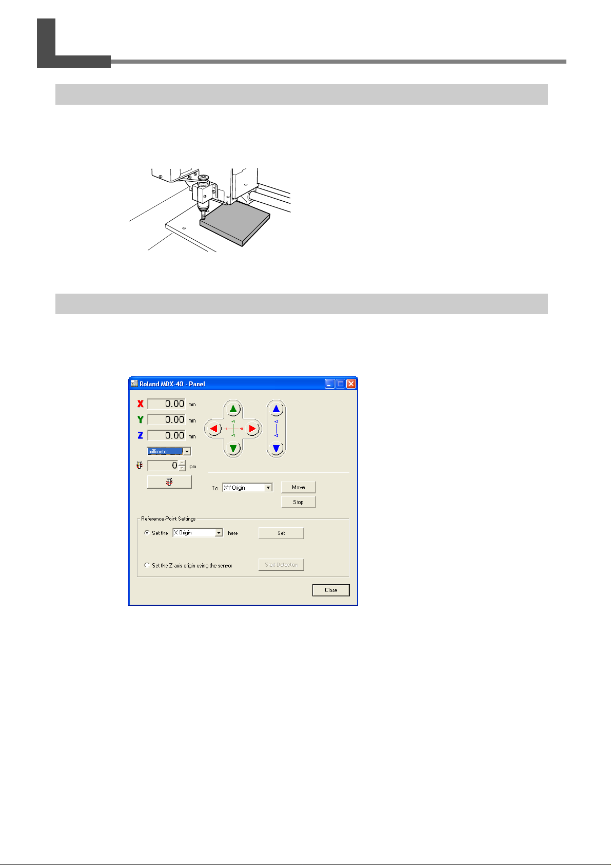
What You Can Do with This Machine
This is a high-speed, high-efficiency modeling machine. You can cut three-dimensional text and shapes by outputting
data from the program included with the machine or from the CAD program you're using.
Operation Screen
T o make the settings for cutter mo vement and the cutting-start location, you use the W indows-based dri ver. To operate
the machine, display the operation panel screen.
16
Chapter 1 Introduction
Page 19
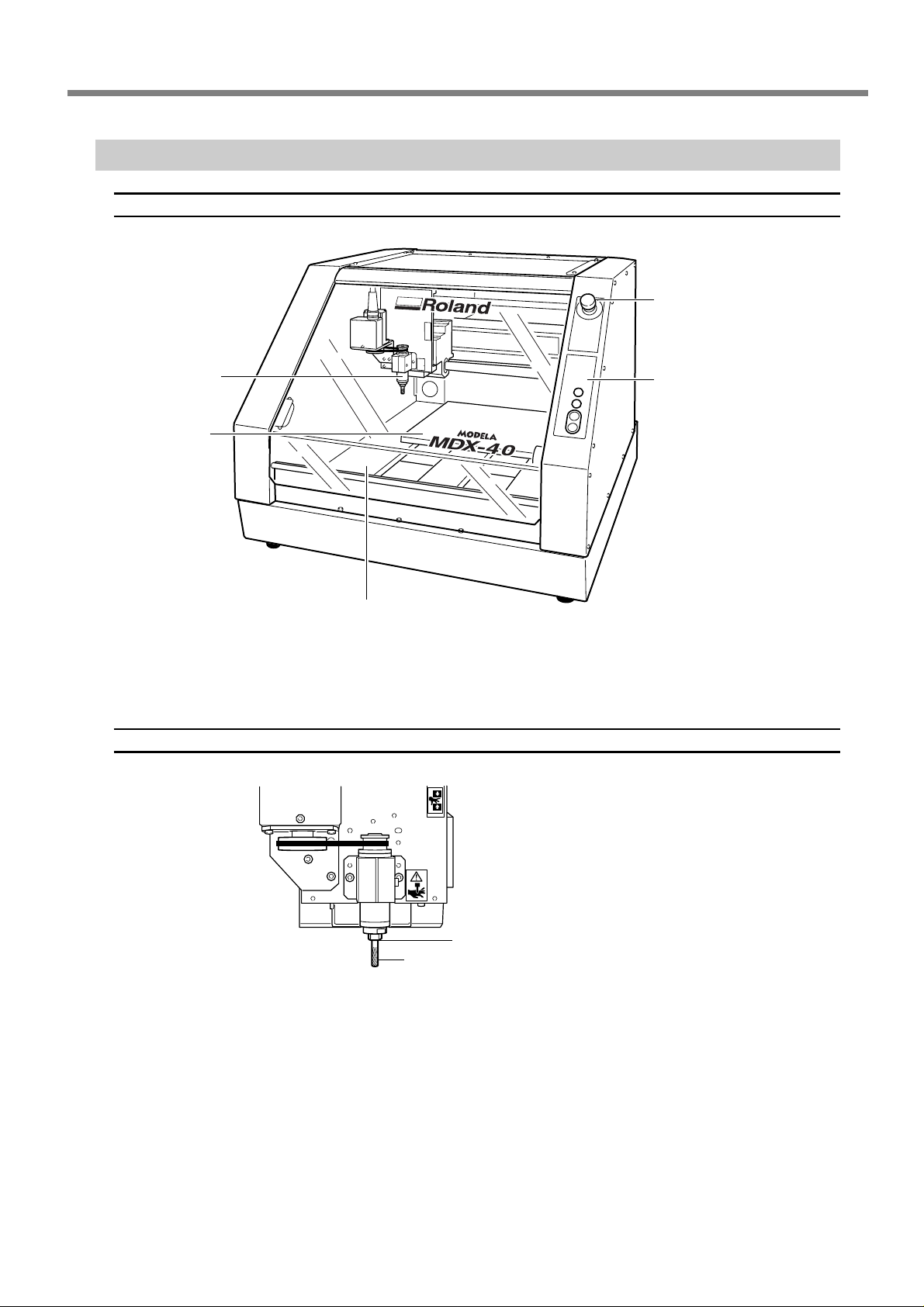
Part Names and Functions
Front View
1-1 Machine Feature
Emergency stop switch
If you press this in an emergency,
the machine operation stops and
the power turns off.
Spindle
Table
Spindle
Operation buttons
You use this to switch the sub
power on and off and to move the
tool up and down.
Front cover
If you open the front cover, cutting automatically stops for your
safety.
Collet
Cutting tool
Chapter 1 Introduction
17
Page 20
1-1 Machine Feature
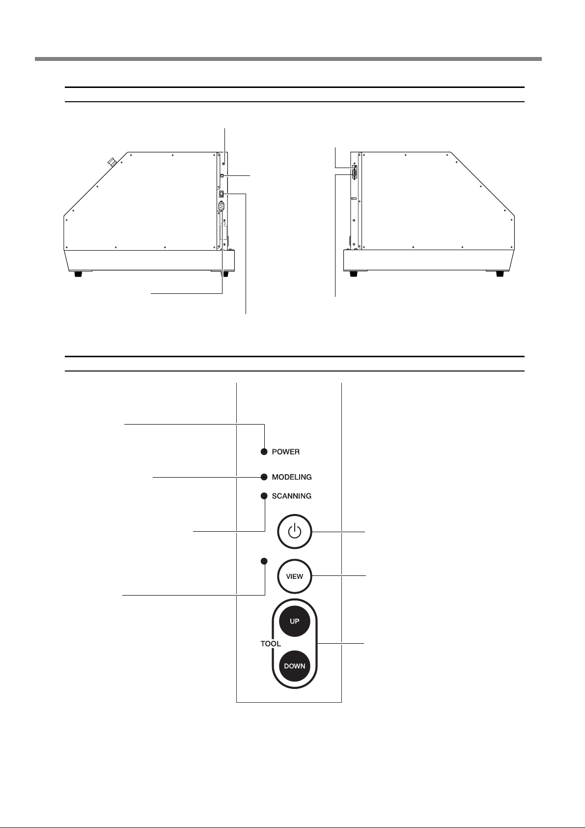
Side view
Expansion connector
Power connector
Connect the supplied power cord to this
connector.
Operation buttons
Sensor connector
Connect the supplied sensor
cable to this connector.
USB connector
Connect a USB cable
(sold separately) to this
connector.
Expansion connector
Main Power switch
This is the machine's main power
switch.
Power light
Lights up when the machine is operating.
MODELING light
This lights up when the Sub po wer button is pressed.
SCANNING light (optional)
This lights up while using the optional
scanning unit.
VIEW light
Lights up when the machine is temporarily stopped. While the light is on, the
machine does not receive processing
data.
Sub power button
Press this button to start the machine when
the main power switch is on.
VIEW button
Press this button to temporarily stop the machine and move the cutter to the top position.
To restart the machine, press the button once
again.
TOOL-UP/TOOL-DOWN button
These buttons move the spindle head up and
down.
T o stop cutting, pause the machine, then press
these two buttons at the same time. This deletes all data sent to the machine.
18
Chapter 1 Introduction
Page 21
1-1 Machine Feature
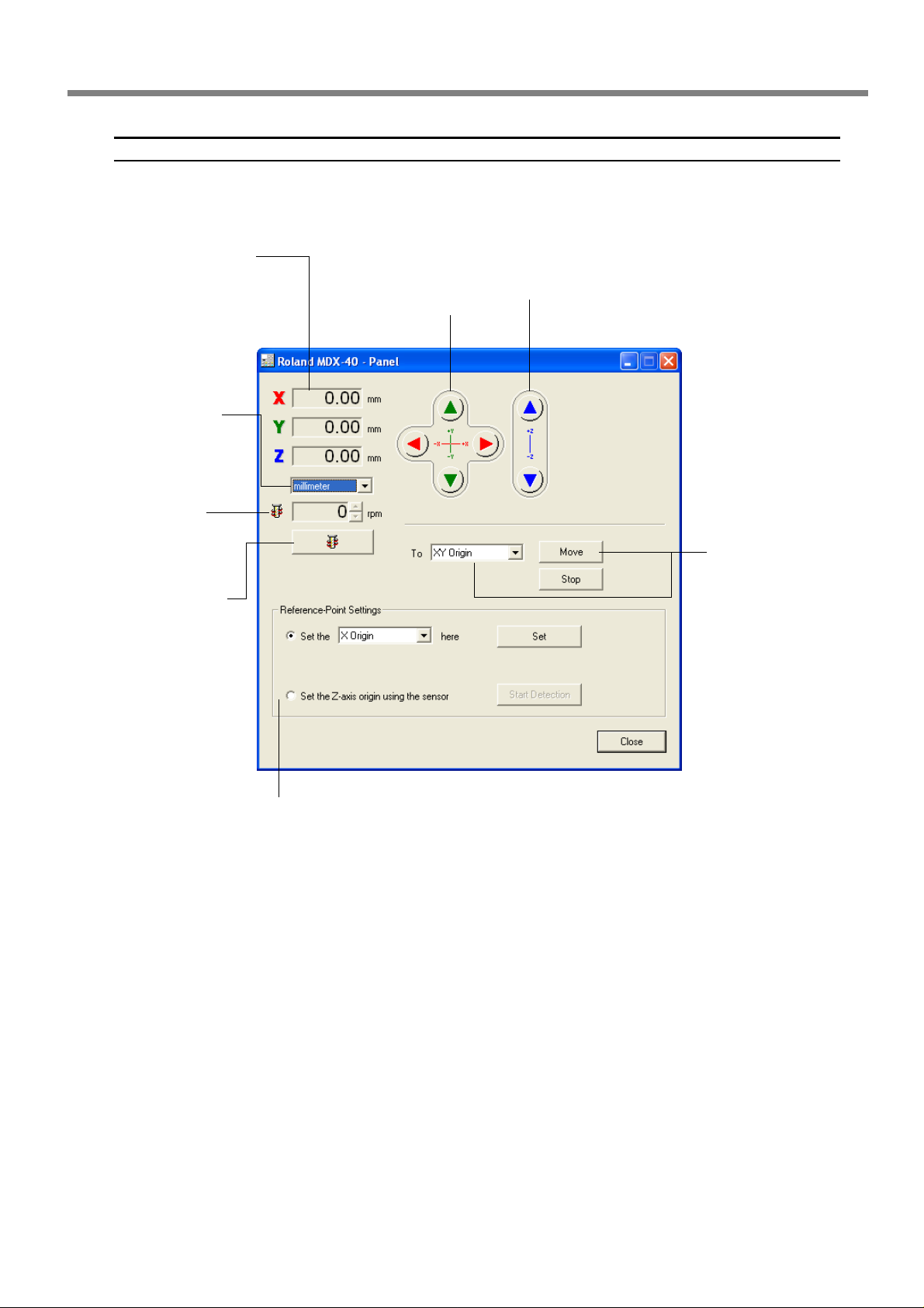
Operation panel screen
T o make the settings for cutter mov ement and the cutting-start location, you use the W indows-based driv er. T o oper ate
the machine, display the operation panel screen.
X-, Y-, and Z-axis coordinates
These display the present coordinate values (workpiece
coordinate system) for the X,
Y, and Z axes.
Unit of measurement for display
This switches the measurement unit for the
window display to millimeters, inches, or
steps.
Spindle-rotation
This set the rotation of
the spindle.
Spindle-rotation
button
This switches spindle
rotation on and off.
XYZ movement buttons
These move the spindle in the X,
Y, and Z directions.
Moving to the
Specified Location
This moves to the specified location in a single
step. You can quit moving by clicking [Stop].
Reference-Point Settings
These set the cutting-start location.
You use these to set the origin point at the selected
location and to detect the selected origin.
Chapter 1 Introduction
19
Page 22
1-1 Machine Feature
The Machine's Coordinate Systems
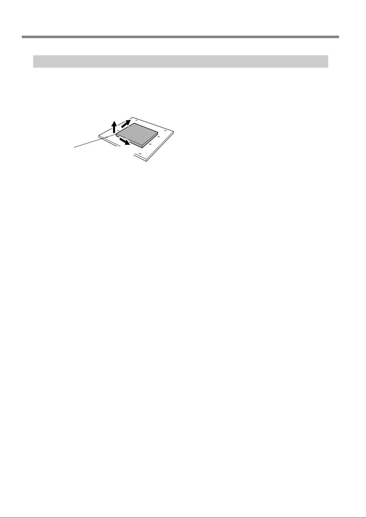
You can freely change the locations of the origin points for this machine. The coordinate values for the axes are
referenced to these origin points. Changing the locations of the origins makes the coordinate values change as well.
This kind of coordinate system is called a "workpiece coordinate system."
Y axis
Z axis
XYZ origin
X axis
20
Chapter 1 Introduction
Page 23

Chapter 2
Prepar ation
21
Page 24
2-1 Included Items
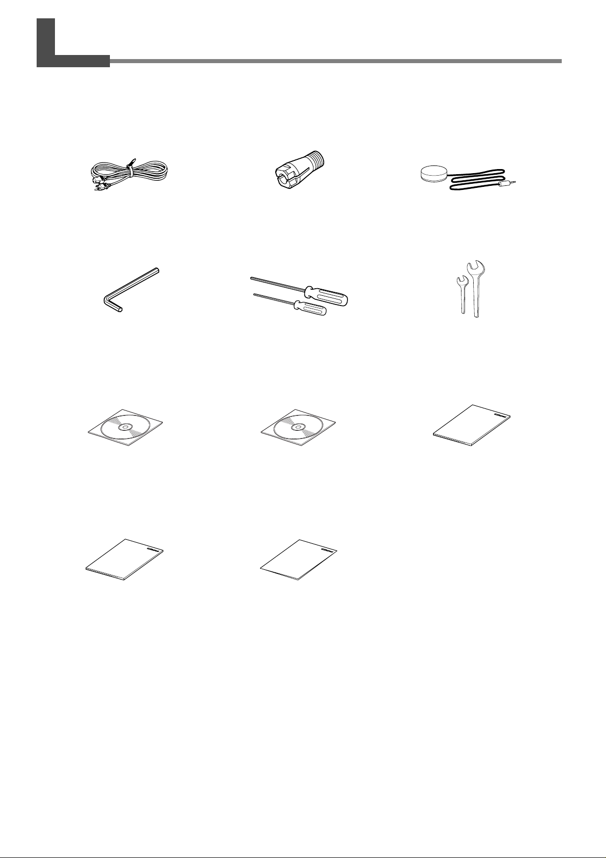
The following items are included with the machine. Make sure they are all present and accounted for.
Power cord
Hexagonal wrench Spanners
Roland Software Package
CD-ROM
Hexagonal screw drivers
Collet
MODELA Player4
CD-ROM
User's Manual (this document)
Sensor
22
Roland Software Package
Installation and Setup Guide
Chapter 2 Preparation
MODELA Player 4
Installation and Setup Guide
Page 25
2-2 Installation
Installation Environment
WARNING
WARNING
WARNING
CAUTION
Unsuitable Installation Sites
➢ Locations subject to large fluctuations in temperature or humidity
➢ Locations subject to shaking or vibration
➢ Locations where the floor is tilted, not level, or unstable
➢ Dusty locations
➢ Locations exposed to direct sunlight or near air-conditioning or heating equipment
➢ Locations exposed to considerable electrical or magnetic noise, or other forms of electromagnetic energy
Never install in a location exposed to water or to gasoline, thinner, or any other
flammable material.
Current leakage ma y cause electrical shock, electrocution, or combustion and fire.
Never place gasoline, alcohol, thinner, or any other flammable material near the
machine. Also, never use an aerosol spray near the machine.
Doing so may cause fire.
Never operate in a location such as one near an open flame or heater, or where
sparking or static electricity may occur.
Cuttings or the like may ignite and cause fire.
Install on a stable surface.
Failure to do so may result in the unit tipping over, leading to injury.
Installation Space
700 (W) x 800 (D) x 600 (H) mm (28 (W) x 32 (D) x 24 (H) in.)
Chapter 2 Preparation
23
Page 26
2-2 Installation
Remo ving the Retainers
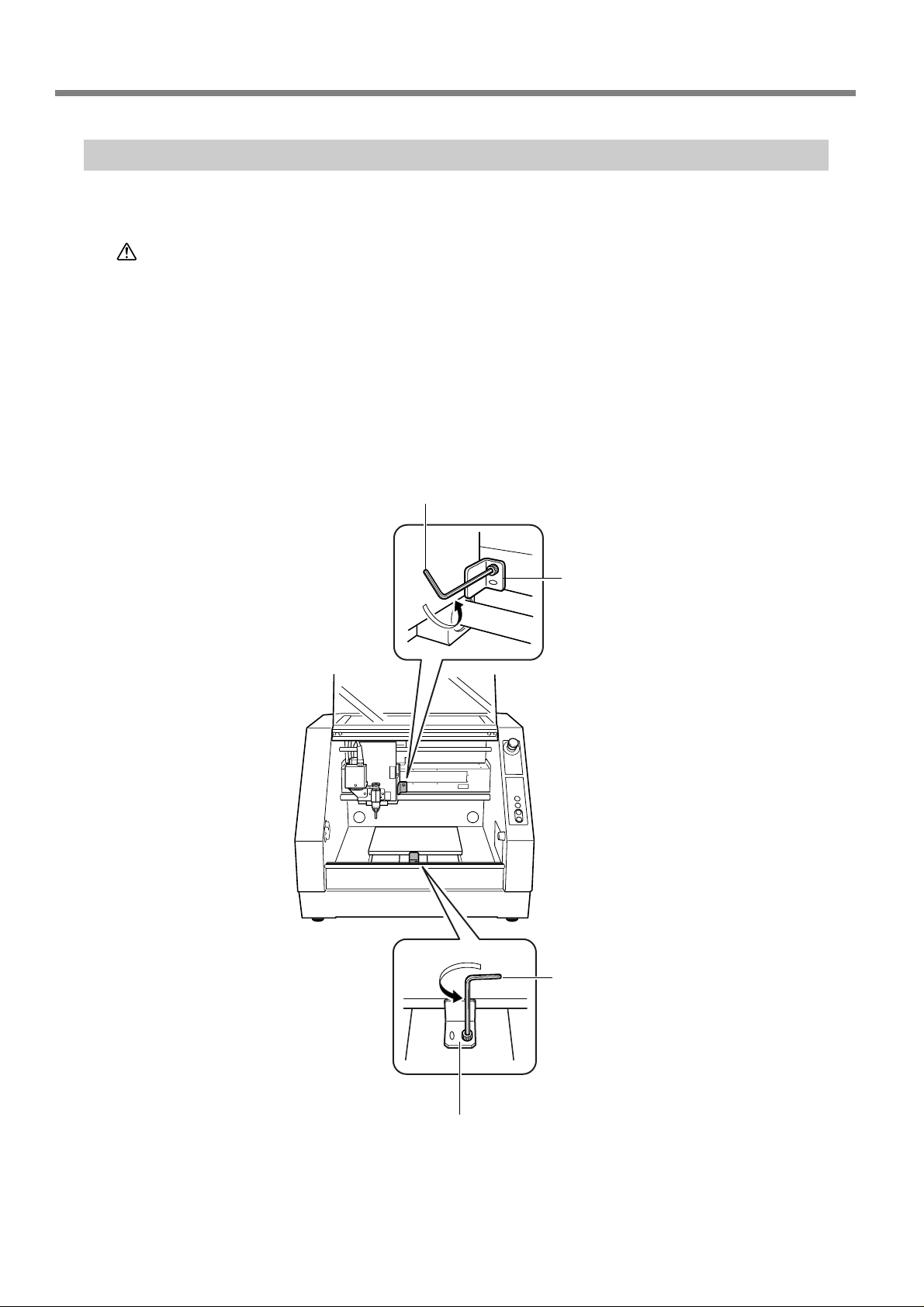
Retainers are attached to the machine to protect it from vibration during transportation. When installation is complete,
remove these.
CAUTION
➢
Remove all retainers. Any that remain may cause faulty operation or breakdown when the power is switched
on.
➢
Store these retainers car efully , because they are needed again when transporting the machine for relocation or
the like.
Remove the screws shown in the figure, then detach these retainers.
➊
Mount the screws at its original location on the machine.
➋
Perform this task with all pow er switches left switched off.
Otherwise sudden movement of the machine may cause injury.
Hexagonal wrench
Retainer
24
Hexagonal wrench
Retainer
Chapter 2 Preparation
Page 27
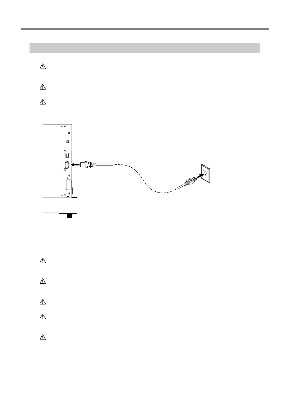
Connecting the Power Cord
2-2 Installation
WARNING
WARNING
CAUTION
Machine
Do not use with any electrical power supply that does not meet the ratings displayed on the unit.
Use with any other power supply may lead to fire or electrocution.
Ground the unit with the ground wire.
Failure to do so may r esult in risk of electrocution in the event of a mechanical problem.
Perform this task with all power s witches left s witched off.
Otherwise sudden movement of the machine ma y cause injury.
Connecting/disconnecting
the cord
Be sure to turn off the machine before connecting/disconnecting the
power cord. Also, be sure to connect the cables securely so that they
will not accidentally disconnect
while the machine is operating.
Power cord
Power outlet
Important Notes on the Power Cord
WARNING
WARNING
WARNING
WARNING
WARNING
Never damage the power cord or pull it with force.
Doing so may tear the cord's insulation, causing an electrical short and resulting in electrical shock, electrocution, or fir e.
Never place any object on the power cord, bend the power cord using excessive
force, or allow the power cord to become deformed.
If it becomes deformed, the deformed location may grow hot and cause fir e.
Never use the machine with the power cord bound into a bundle or roll.
If the cord is in a bundle or roll, it may grow hot and cause fire.
Never use any power cord other than the power cord included with the machine.
Also, never use a power strip or extension cord.
The power strip or extension cord may grow hot and cause fire.
Do not use with a damaged power cord or plug, or with a loose electrical outlet.
Doing so may lead to fire, electrical shock, or electrocution.
Chapter 2 Preparation
25
Page 28
2-2 Installation
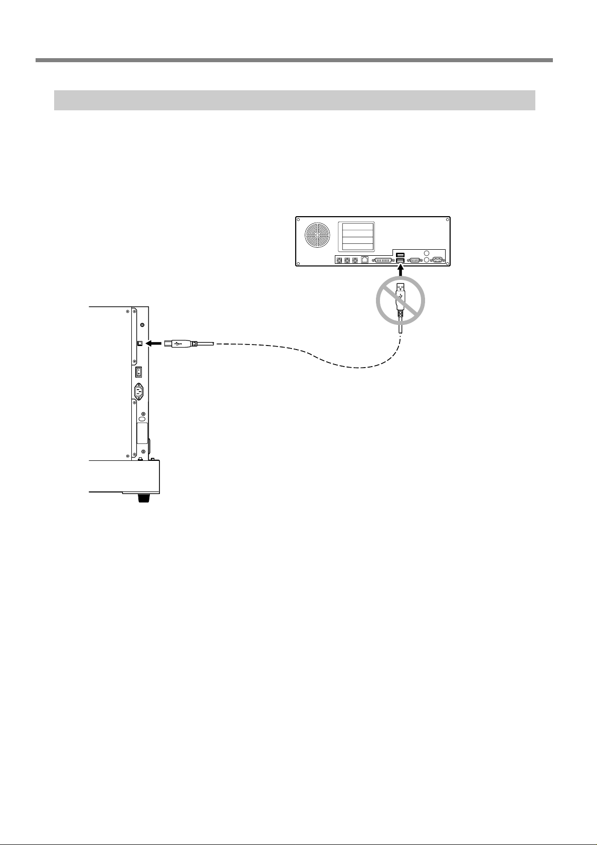
Installing the Windows-based Driver and Connecting to the Computer
➢
Installing the driver following "Roland Software Package Installation and Setup Guide"
➢
Be sure to make the connection between the machine to the computer during the course of installing the
driver. If the cable connection is made befor e you start installation of the driver, driver installation may fail and
the machine may become unusable.
➢
Use a shielded USB cable having a length of 3 meters or less.
➢
Do not use a USB hub or the like.
Computer
Machine
USB cable
Do not connect the USB
cable at this point.
26
Chapter 2 Preparation
Page 29

Chapter 3
Oper ation
27
Page 30
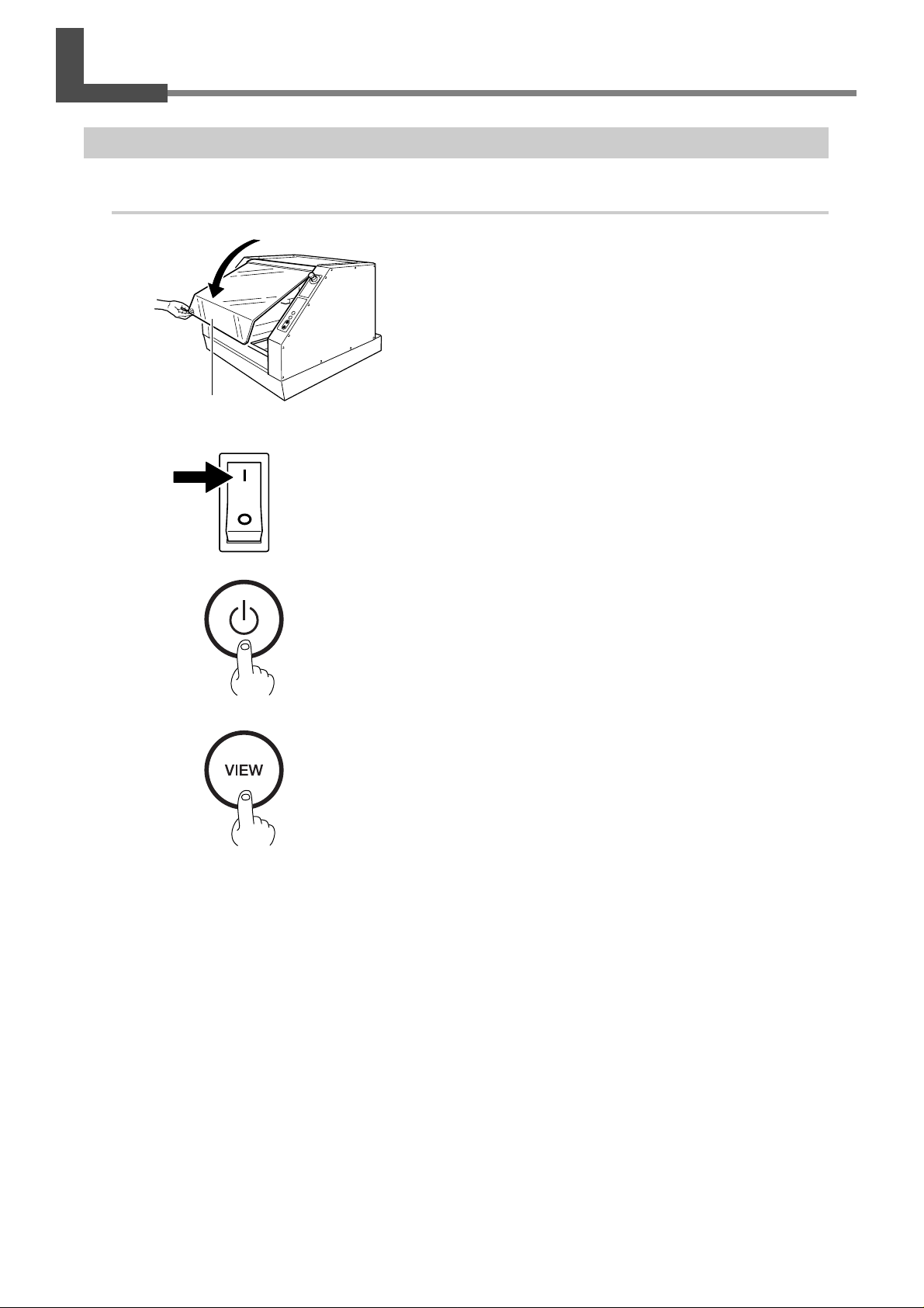
3-1 Switching the Po wer On and Off
Starting the System
1.
Start the machine.
➊
➋
➌
Close the front cover.
Front cover
Switch on the main power switch.
The POWER light comes on.
Press the Sub power button.
The machine starts up, and initialization is performed.
After initialization ends, the MODELING light and the VIEW light
comes on and the machine is paused.
➍
Press the VIEW button.
The view state is canceled, and the machine finishes preparations
for receiving cutting data.
28
Chapter 3 Operation
Page 31
3-1 Switching the Power On and Off
2.
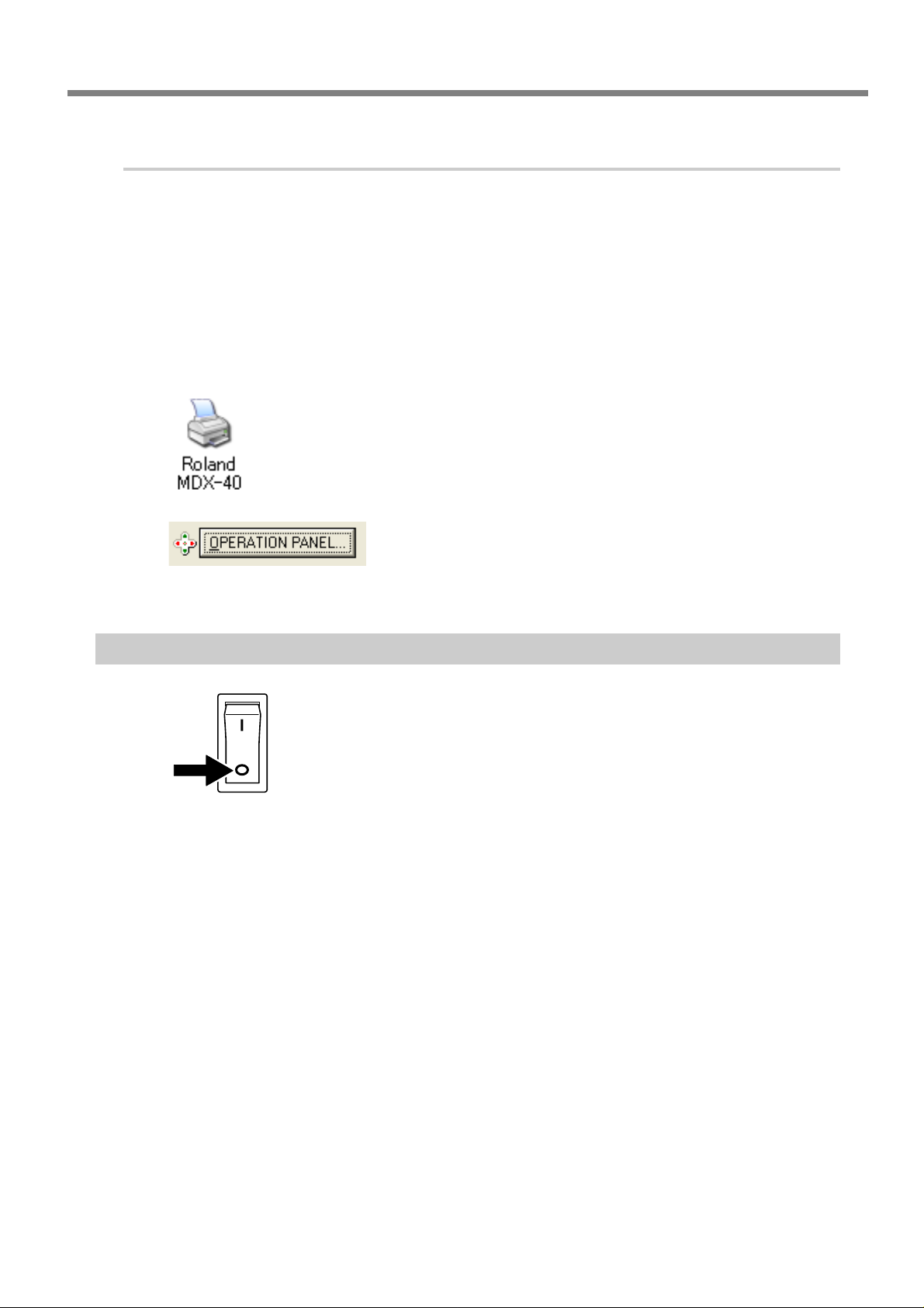
Start the operation panel screen.
Open the operation panel screen.
From the operation panel screen, you can make the settings for cutter movement and the start location for cutting.
If You're Using Windows XP
➊
From the [Start] menu, click [Control Panel].
Click [Printers and Other Hardware], then click [Printers and Faxes].
If You're Using Windows 98/Me/2000
From the [Start] menu, click [Settings], then [Printers].
➋
➌
Switching Off the Power
Switch off the main power switch.
The POWER light goes dark and the power to the machine is switched off.
Right-click the [Roland MDX-40] printer icon.
If You're Using Windows XP/2000
Click [Printing Preferences].
If You're Using Windows 98/Me
Click [Properties].
Click the [Option] tab.
Click the [OPERATION PANEL] button.
The operation panel screen open.
Chapter 3 Operation
29
Page 32
3-2 Emergency Stop to Ensur e Saf ety
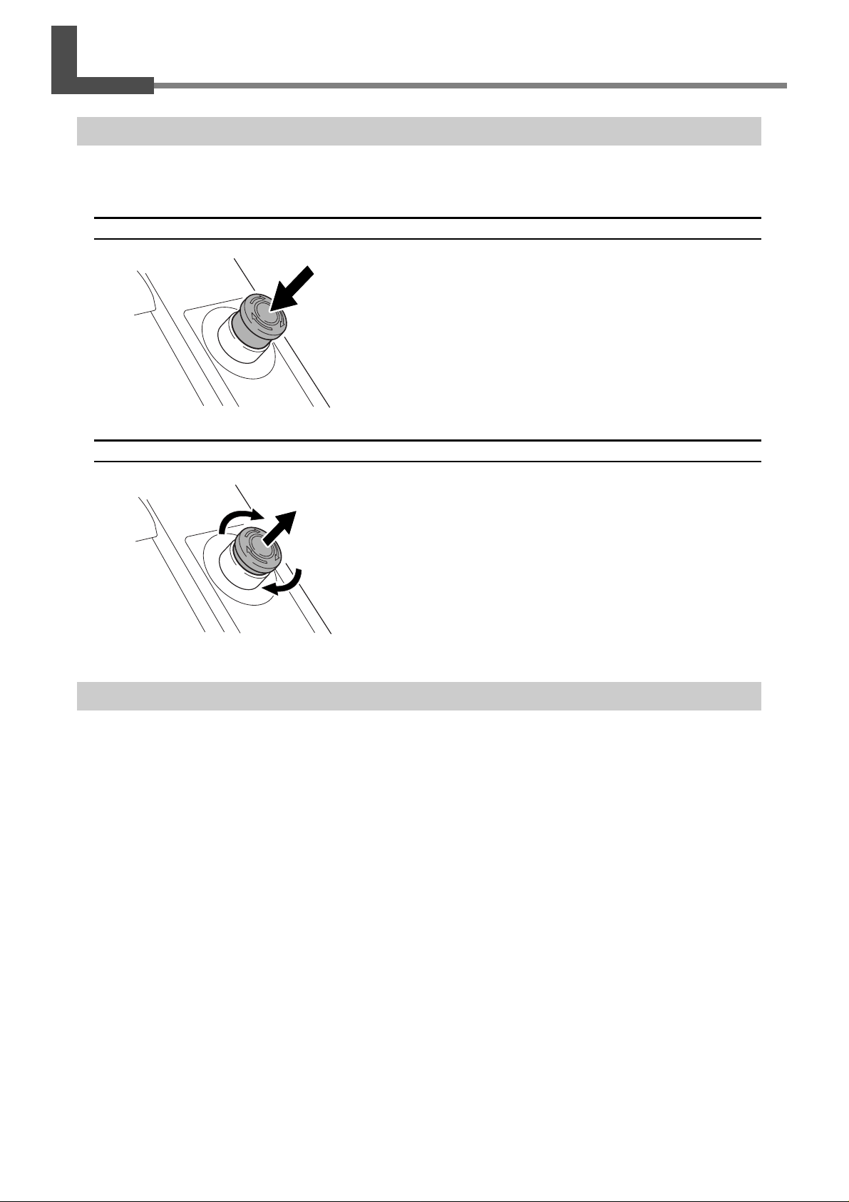
Emergency stop switch
This switc h stops the machine in an emergenc y in order to avoid danger. Pressing the emergency stop switc h immediately halts operation and aborts cutting.
How to Perform an Emergency Stop
Press the switch.
Releasing the Emergency Stop Switch
Turning the switch in the direction of the arrow releases the emergency stop switch.
Fr ont Cover
For safety, opening the front cover during operation stops cutting and makes the MODELING and VIEW lights flash.
To recover from this, close the front cover and switch off the sub power button.
It is possible to open the front cover while the machine is paused. When the front co ver is open, the VIEW light flashes
every two seconds. Closing the cover stops the flashing.
☞ P.34"Stopping and Pausing Cutting"
30
Chapter 3 Operation
Page 33
3-3 Installing a Tool and Setting the Cutting-start Location
The Locations of the Origin Points
When you perform cutting using a work plate, you set three origin points: the X, Y, and Z origins. The X and Y origin
points serve as the start location for cutting. You normally align the Z origin point with the surface of the workpiece. In
any case, make the settings to match the size of the workpiece and the length of the cutter.
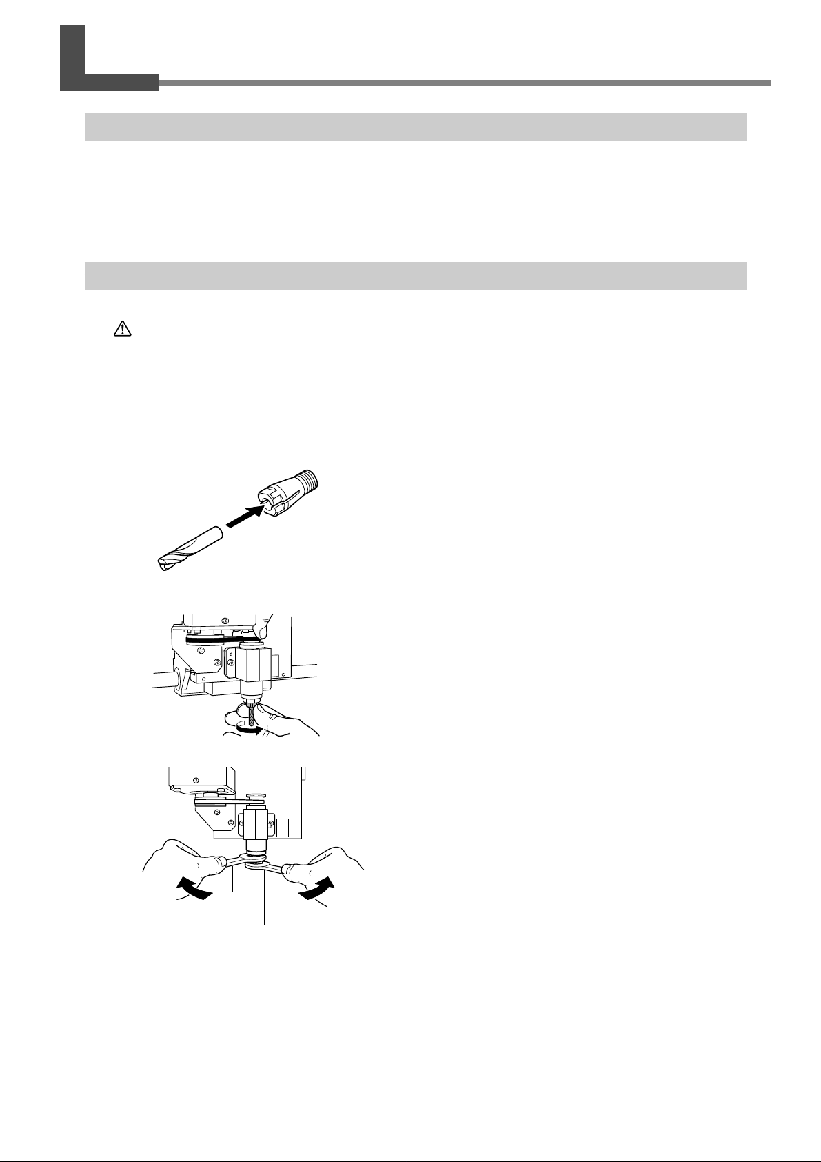
Installing a Tool
CAUTION
Close the front cover.
➊
Press the VIEW button to make the VIEW light come on.
The table moves back toward you.
Wait until operation has stopped completely, then open the front cover.
➋
➌
➍
Do not touch the tip of the blade with your fingers.
Doing so may result in injury.
Insert the tool into the collet.
Collet
Tool
Insert the collet chuck and tool from underneath.
While supporting the tool to keep it from falling, turn the
collet chuck to secure it in place.
➎
Spanner
(large)
Spanner
(small)
Tighten the collet using spanners.
Chapter 3 Operation
31
Page 34
3-3 Installing a Tool and Setting the Cutting-start Location
Setting the Cutting-start Location
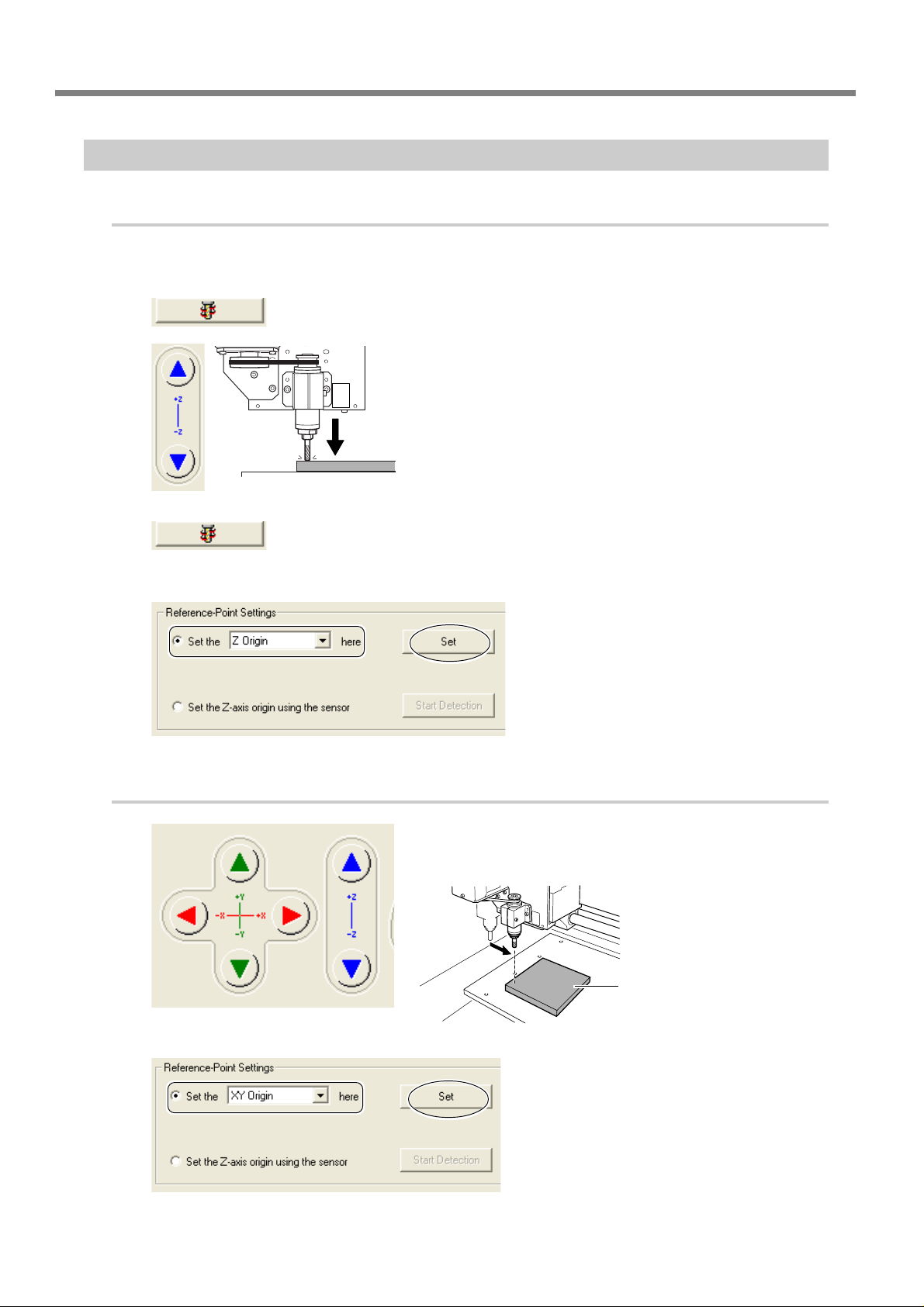
1.
Set the Z origin point.
Close the front cover.
➊
Press the VIEW button to make the VIEW light go out.
➋
➌
➍
➎
Using the operation panel screen, press the button in the
figure.
Bring the tool lightly into contact with the surface of the
workpiece while rotating the spindle.
Workpiece
At the location where the workpiece surface begins to be
cut slightly, stop rotating the spindle.
Select [Set the Z origin here].
Click [Set].
The Z origin point has now been set.
2.
Set the XY origin point.
➊
➋
Move the spindle to the cutting-start location.
Move the spindle to a location slightly above the workpiece.
Workpiece
Table
Select [Set the XY origin here].
Click [Set].
The XY origin point has now been set.
32
Chapter 3 Operation
Page 35
3-4 Starting Cutting
CAUTION
CAUTION
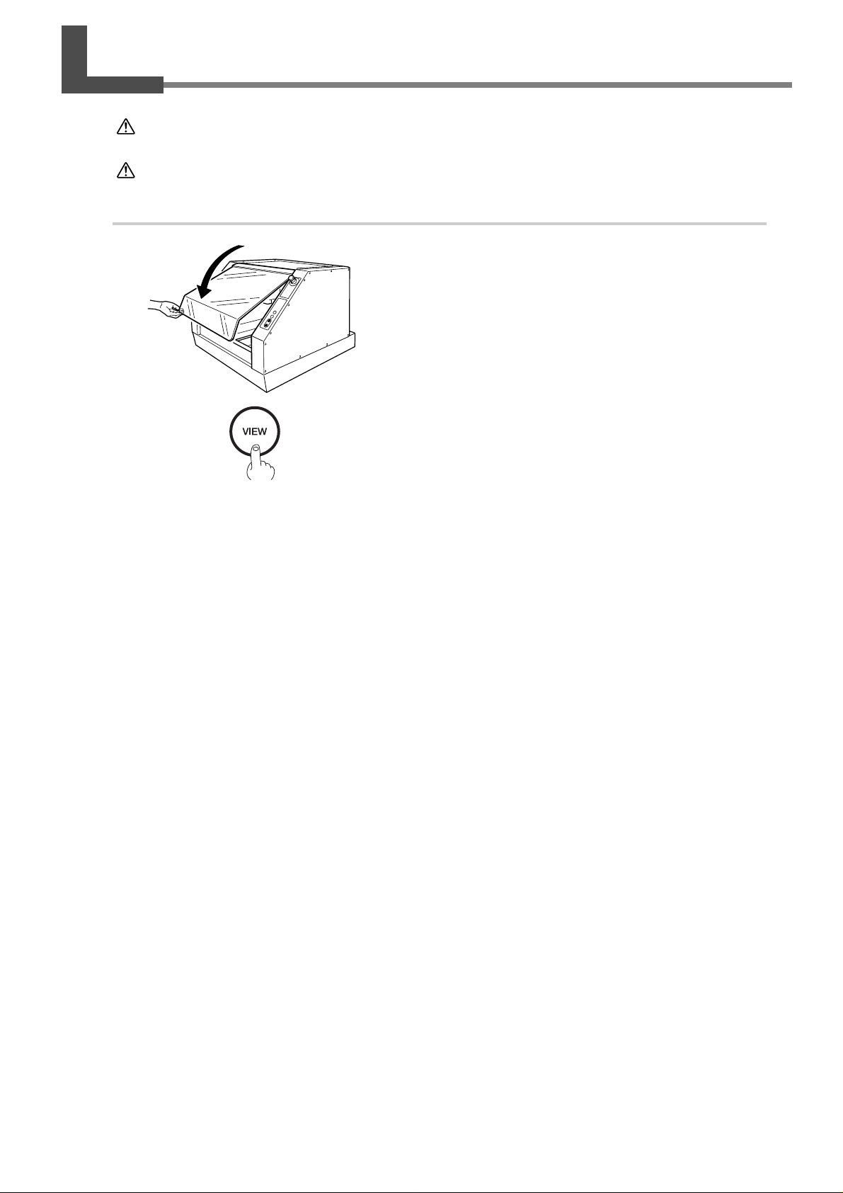
Procedure
Perform dry cutting with no cutting oil.
Such materials can cause fire.
Never operate if a front cover is cracked or broken.
Doing so may result in injury. If the front cover is cracked, contact your authorized.
➊
➋
Send the cutting data from the computer.
➌
Close the front cover.
If the VIEW light is on, press the VIEW button to make the
light go dark.
Chapter 3 Operation
33
Page 36
3-5 Stopping and P ausing Cutting
Pausing Cutting
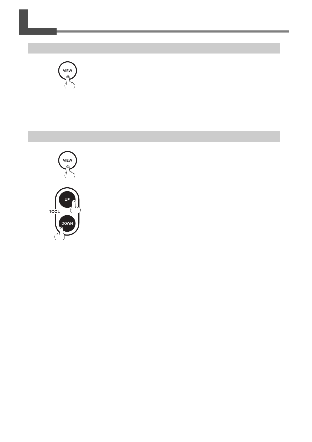
Press the VIEW button.
Pressing the VIEW button moves the spindle to the left edge and the table to the
front of the machine.
It is possible to open the front cover while the machine is paused. Before you open the front cover, make sure that
operation has stopped completely.
To resume cutting, make sure the front cover is closed, then press the VIEW button again.
Stopping Cutting
➊
➋
Press the VIEW button.
Press the TOOL-UP/TOOL-DOWN buttons at the same time.
The VIEW light flashes, and deletion of the data sent to the machine begins.
When deletion of the data ends, the VIEW light stops flashing.
34
Chapter 3 Operation
Page 37

Chapter 4
Featur e Reference
35
Page 38
4-1 Setting the Z Origin Using the Sensor
Setting the Z origin on the Workpiece
1.
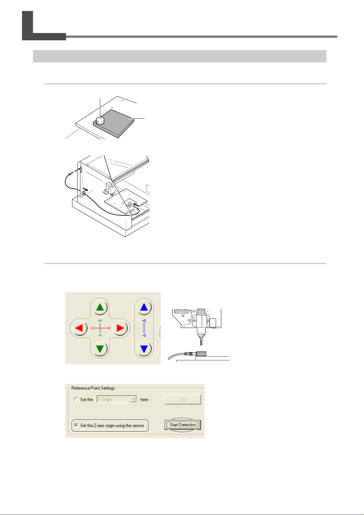
Mount the sensor.
➊
➋
Sensor cable
2.
Set the Z origin point.
Sensor
Place the sensor on the workpiece.
Workpiece
Run the sensor cable around behind the machine to the top of the table.
Connect the sensor cable to the sensor connector.
Close the front cover.
➊
Press the VIEW button to make the VIEW light go out.
➋
Using the operation panel screen, move the tool to a location above the sensor.
➌
Select "Set the Z-axis origin using the
sensor."
Click "Start Detection."
36
Chapter 4 Feature Reference
Page 39
4-1 Setting the Z Origin Using the Sensor
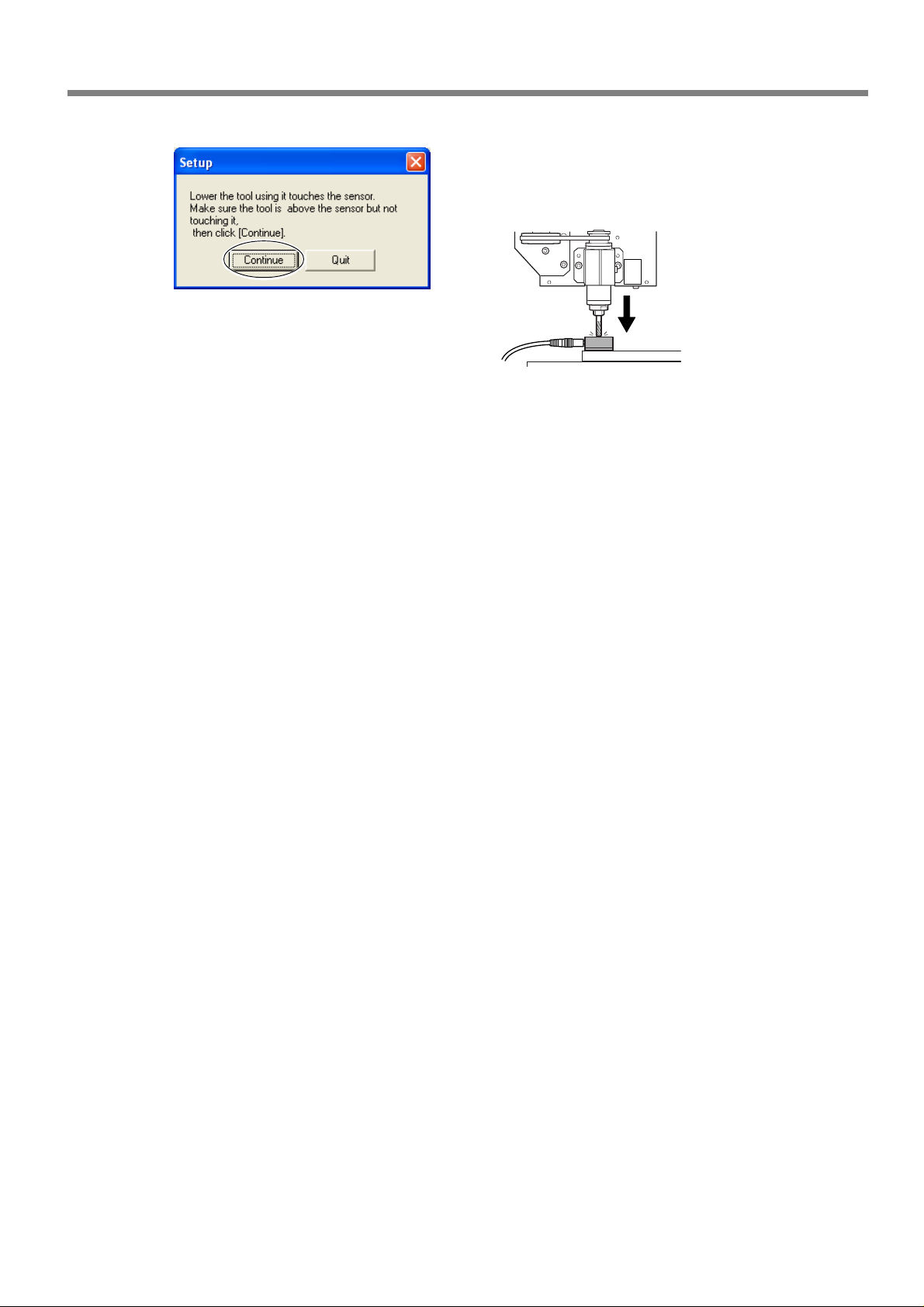
➍
Detach the sensor and sensor cable.
➎
Click "Continue."
The cutter automatically makes contact with the sensor , and the Z-axis origin point is set the sufface of the
workpiece.
Chapter 4 Feature Reference
37
Page 40
4-2 Installing the Engra ving Cutter
Installing a Cutter and Setting the Origin Point for Machining
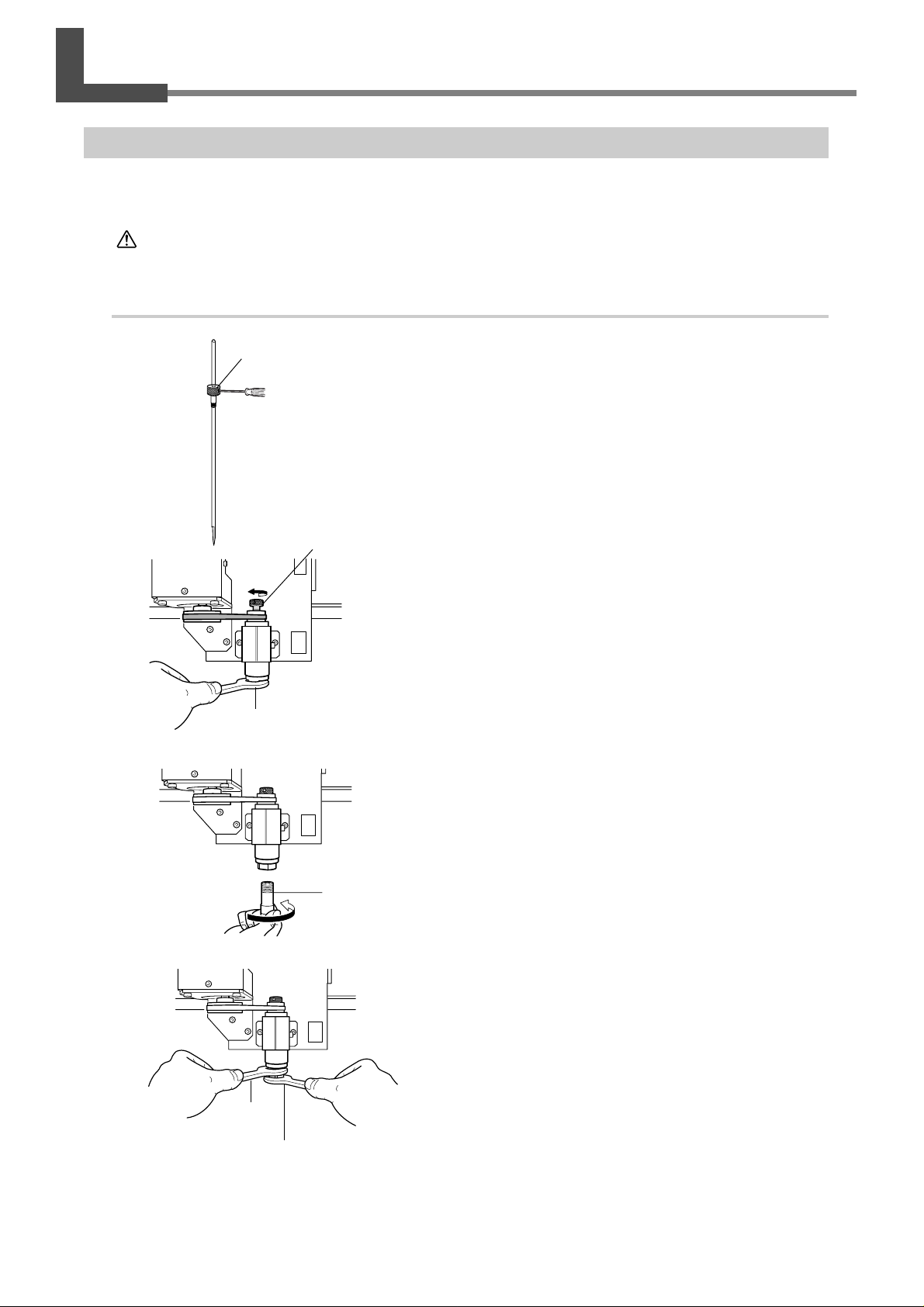
When using a engraving cutter, the optionally available engraving cutter and collet.
CAUTION
1.
Installing a cutter and setting the Z point for machining.
➊
➋
Do not touch the tip of the blade with your fingers.
Doing so may result in injury.
Cutter holder
Hexagonal screw driver
(small)
Cutter holder
Detach the cutter holder from the cutter.
While using a spanner to hold the spindle immobile, tighten
the cutter holder sufficiently.
The cutter holder is reverse-threaded (that is, you turn it counterclockwise to tighten it). Be careful to turn it in the correct direction.
➌
➍
Spanner(large)
Insert the collet from underneath.
Collet
Tighten the collet using spanners.
Spanner
(large)
Spanner
(small)
38
Chapter 4 Feature Reference
Page 41
4-2 Installing the Engraving Cutter
➎
➏
➐
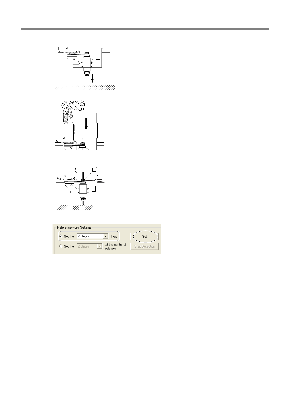
Lower the spindle and bring the tip of the collet close to
the surface of the workpiece.
Insert the cutter.
Cutter
Tool retaining screw
Making the tip of the cutter touch the surface of the
workpiece, and tighten the tool retaining screw.
Hexagonal screw driver
(small)
➑
Using the operation panel screen, select
[Set the Z origin here].
Click [Set].
The Z origin has now been set.
Chapter 4 Feature Reference
39
Page 42
4-2 Installing the Engraving Cutter
2.
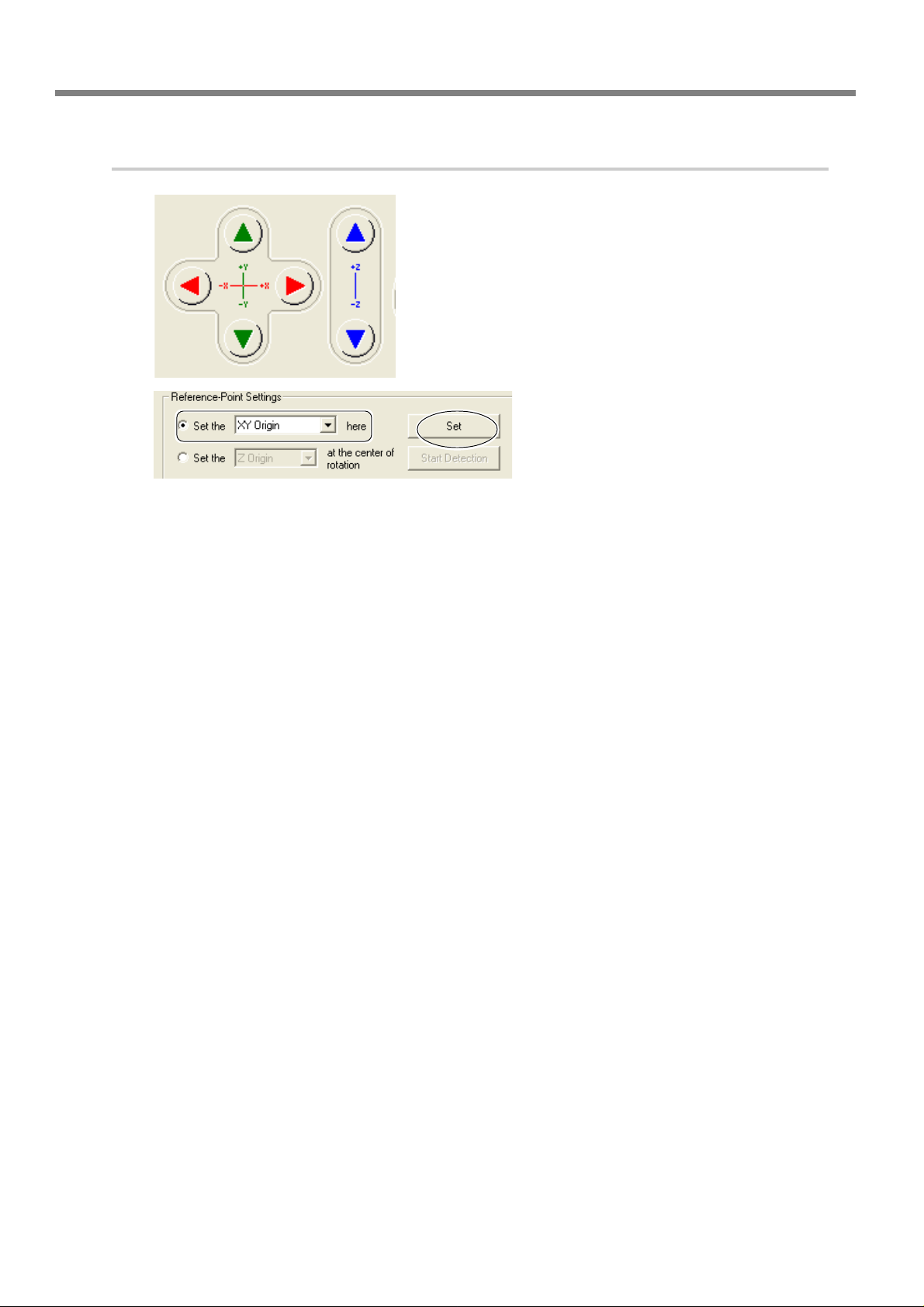
Make the setting for the XY origin point.
➊
➋
Using the operation panel screen, move the
spindle to the cutting-start location.
Select [Set the XY origin here].
Click [Set].
The XY origin has now been set.
40
Chapter 4 Feature Reference
Page 43

Chapter 5
Appendix
41
Page 44
5-1 Maintenance
Daily Care
This section describes the maintenance methods for day-to-day care of the machine.
WARNING
WARNING
CAUTION
CAUTION
CAUTION
➢
This machine is a precision device, and is sensitive to dust and dirt. Perform cleaning on a daily basis.
➢
Never use a solvent such as thinner or benzine.
➢
Clean cuttings carefully.
➢
To clean the cover, use a dry cloth to wipe it.
➢
Never attempt to oil or lubricate the machine.
Never use an air gun (blower) to remove cuttings.
Using an air gun (blower) may blow cuttings inside the machine, creating a fire hazard.
Never use gasoline, alcohol, thinner, or any other flammab le material.
Doing so may cause fire.
Switch off the machine and unplug the power cord from the electrical outlet before performing cleaning or maintenance.
Failure to do so may result in injury or electrical shock.
Do not touch the spindle motor immediately or cutter after a cutting operation
has ended.
Doing so may result in burns.
Use a brush to remove cuttings.
Attempting to use a vacuum cleaner to take up cuttings may cause fire in the vacuum
cleaner.
Spindle Inspection
The spindle unit and the belt are parts that wear out. As a general guide, you should replace them after every 2,000
hours of use.
As a general guide, replace the spindle motor after every 6,000 hours of use.
42
Chapter 5 Appendix
Page 45

5-2 What to Do If
The machine doesn't run.
Is the power switched on?
Start the machine and make sure the POWER and MODELING lights come on.
☞ P.28"Switching the Power On and Off"
Is the front cover open?
Close the front cover.
Is the VIEW light on?
When the VIEW light is on, operation is paused.
When the VIEW light is on, cutting does not start even when
data is sent. Press the VIEW button to cancel the paused
state.
Is the lights flashing an error message?
☞ P.43"What to Do If a Flashing Error Is Displayed."
Is a message displayed on the screen?
☞ P.43"What to Do If an Error Message Appears."
Is the cable connected?
Connect the cable securely.
The cutting results are not attractive.
What to Do If a Flashing Error Is Displayed
If the lights are flashing as shown below, then an error has occurred on the machine. To correct the error, follow the steps described below.
The MODELING and SCANNING lights
An error occurred during initialization of the machine or during origin detection by the sensor.
Switch the power off, then back on.
If the error is not cleared when you switch the power on
again, the machine may be malfunctioning. Contact your
authorized Roland DG Corp. dealer or service center.
The MODELING and VIEW lights
The front cover was opened while cutting was in
progress.
Operation cannot be continued. Close the front cover and
press the sub power button.
The MODELING light
The spindle motor error occurred.
Operation cannot be continued. Press the sub power button to clear the error. Make the program's cutting parameters more relaxed to lessen the load applied to the spindle.
Is the workpiece securely mounted in place?
Mount the workpiece in place securely , using the appropriate mounting method for the kind of cutting you're performing.
Is the tool securely installed?
Retighten the collet to hold in place securely.
Is the tip of the tool worn?
If the tip of the tool shows wear, then replace with a new
tool.
What to Do If an Error Message Appears
This section describes the error messages that may
appear on the monitor of the computer you're using, and how to take action to remedy the problem.
If the action described here does not correct the
problem, or if an error message not described here
appears, contact your vendor or the nearest Roland
DG Corp. service center.
[The machine is not responding.]
The machine and the operation panel screen cannot communicate because the power to the machine
has been interrupted or the USB cable has come
loose.
Start the machine, or make sure the USB cable is connected
securely. After checking, open the operation panel screen
again.
Chapter 5 Appendix
43
Page 46

5-2 What to Do If
[Operation or view in progress. Please wait until
operation stops, or cancel the view.]
An attempt was made to perform an operation or
make settings using the operation panel screen while
the machine was either in operation or paused.
The operation panel screen cannot be used to start a new
operation or make new settings while an cutting operating
is in progress or when the machine is paused. Either wait
until the operation ends or cancel the paused state, then
carry out the operation or make the settings.
[No sensor is connected.]
The sensor was not connected to the machine during origin-detection operation.
Make sure the sensor is installed on the machine and the
connector is connected.
[Emergency stop -- excess current to spindle. Please
switch off machine power.]
An emergency stop occurred because the spindle
experienced excessive load.
Make the cutting parameters more relaxed, then carry out
cutting again.
If this message appears even after you have changed the
cutting parameters, then contact your authorized Roland
DG Corp. dealer or service center.
[Emergency stop -- voltage drop due to excessive
spindle load.]
An emergency stop occurred because the voltage
drop.
Relax the cutting parameters, allow the machine cool down,
then carry out cutting again.
If this message appears even after you have changed the
cutting parameters and allowed the machine to cool, then
contact your authorized Roland DG Corp. dealer or service center.
[Emergency stop -- spindle driver IC overheated.
Please switch off machine power.]
[Emergency stop -- spindle motor overheated.]
An emergency stop occurred because the spindle
motor became too hot.
Relax the cutting parameters, allow the machine cool down,
then carry out cutting again.
If this message appears even after you have changed the
cutting parameters and allowed the machine to cool, then
contact your authorized Roland DG Corp. dealer or service center.
[X-axis [Y-axis/Z-axis/A-axis] limit-switch error.
Please switch off machine power.]
An error occurred during initialization of the machine.
This message may appear if head movement is obstructed
during initialization at startup. Switch the power off, then
back on.
[Settings cannot be saved or r ead. Please switch off
machine power.]
An error occurred either when setting the origin
location or during startup after making the settings.
The origin location could not be c hanged or set. Switch the
power off and back on, then redo the setting for the origin
location.
[Emergency stop -- cov er opened during operation.
Please switch off machine power.]
The front cover was opened during cutting.
Operation cannot be continued. To ensure safety, opening
the front cover causes an emergency stop to occur. Switch
the power off and back on, then redo the cutting.
[Sensor error. Please switch off machine power.]
Origin detection using the sensor cannot be performed.
Origin detection cannot be performed. Switch off the power
and detach the connector for the sensor. Then switch the
power back on and connect the connector for the sensor.
An emergency stop occurred because the spindle
became too hot.
Relax the cutting parameters, allow the machine cool down,
then carry out cutting again.
If this message appears even after you have changed the
cutting parameters and allowed the machine to cool, then
contact your authorized Roland DG Corp. dealer or service center.
44
Chapter 5 Appendix
Page 47
5-3 Locations of the Power Rating and Serial Number Labels
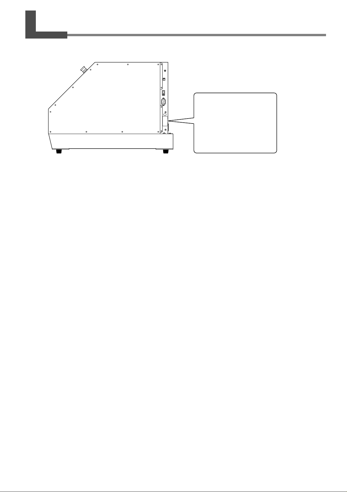
Serial Number
This is require when y ou seek maintenance, servicing, or support. Never
peel off the label or let it get dirty.
Power Rating
Use an electrical outlet that meets the
requirements for voltage, frequency,
and amperage given here.
Chapter 5 Appendix
45
Page 48
5-4 Specifications
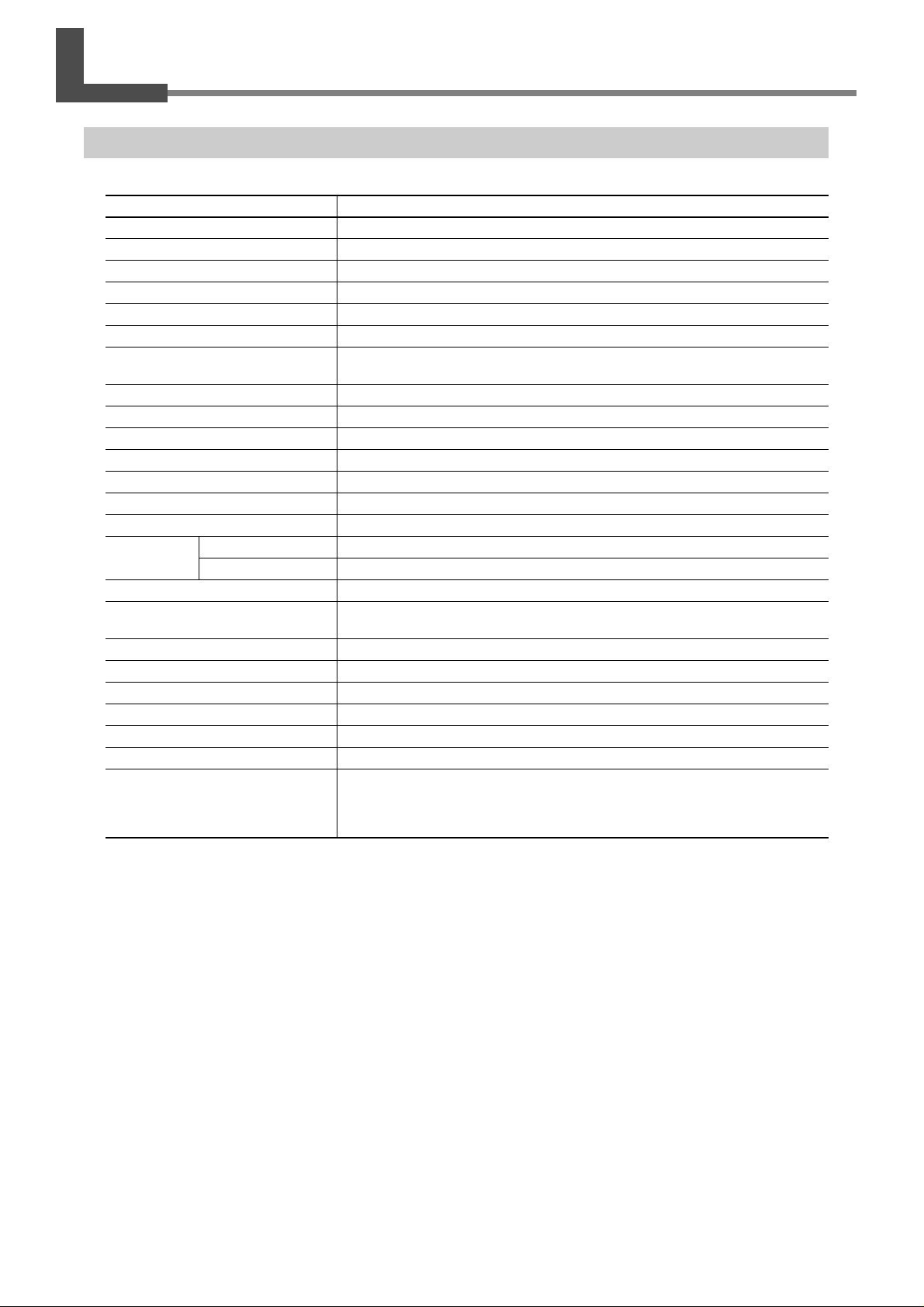
Main Unit Specification
Acceptable material
X, Y, and Z operation strokes
Distance from spindle tip to table
Table size
Loadable workpiece weight
XYZ-axis motor
Feed rate
Software resolution
Mechanical resolution
Spindle motor
Spindle type
Spindle rotation
Tool chuck
Interface
Power supply
Voltage and frequency
Required power capacity
Power consumption
Acoustic noise level
Dimensions
Weight
Packed dimensions
Packed weight
Operation temperature
Operation humidity
Accessories
Resins such as chemical wood and modeling wax(metal not supported)
305 (X) x 305 (Y) x 105 (Z) mm (12 (X) x 12 (Y) x 4-1/8 (Z) in.)
Maximum 125 mm (4-15/16 in.)
305 (W) x 305 (D) mm (12 (W) x 12 (D) in.)
4 Kg (8.8 lb)
Stepping motor
XY-axis : 0.1 to 50 mm/sec. (0.0039 to 1.9 in./s)
Z-axis : 0.1 to 30 mm/sec. (0.0039 to 1.1 in./s)
0.01 mm/step (0.00039 in./step)
0.002 mm/step (0.0001 mm/step)
DC brushless motor, Maximum 100W
Modeling spindle
4500 to 15000 rpm
Cutter holder (4.36 mm)
USB connector, sensor connector, expansion connector
AC100 to 240 ± 10 %, 50/60 Hz
2.1 A
Approx. 210W
No-load operation : 56 dB (A) or less, standby : 42 dB (A) or less (According to
ISO7779)
669 (W) x 760 (D) x 554 (H) mm (26-3/8 (W) x 29-15/16 (D) x 21-13/16 (H) in.)
66 Kg (146 lb)
785 (W) x 885 (D) x 735 (H) mm (31 (W) x 35 (D) x 29 (H) in.)
73 Kg (161 lb)
5 to 40˚C (41 to 104˚F)
35 to 80 % (no condensation)
Power cord, collet, sensor, hexagonal wrench, hexagonal screw drivers, span-
ners, Roland Software Package CD-ROM, MODELA Player4 CD-ROM, user's
manual, Roland Software P ackage installation and setup guide, MODELA Pla yer4
installation and setup guide
MDX-40
46
Chapter 5 Appendix
Page 49
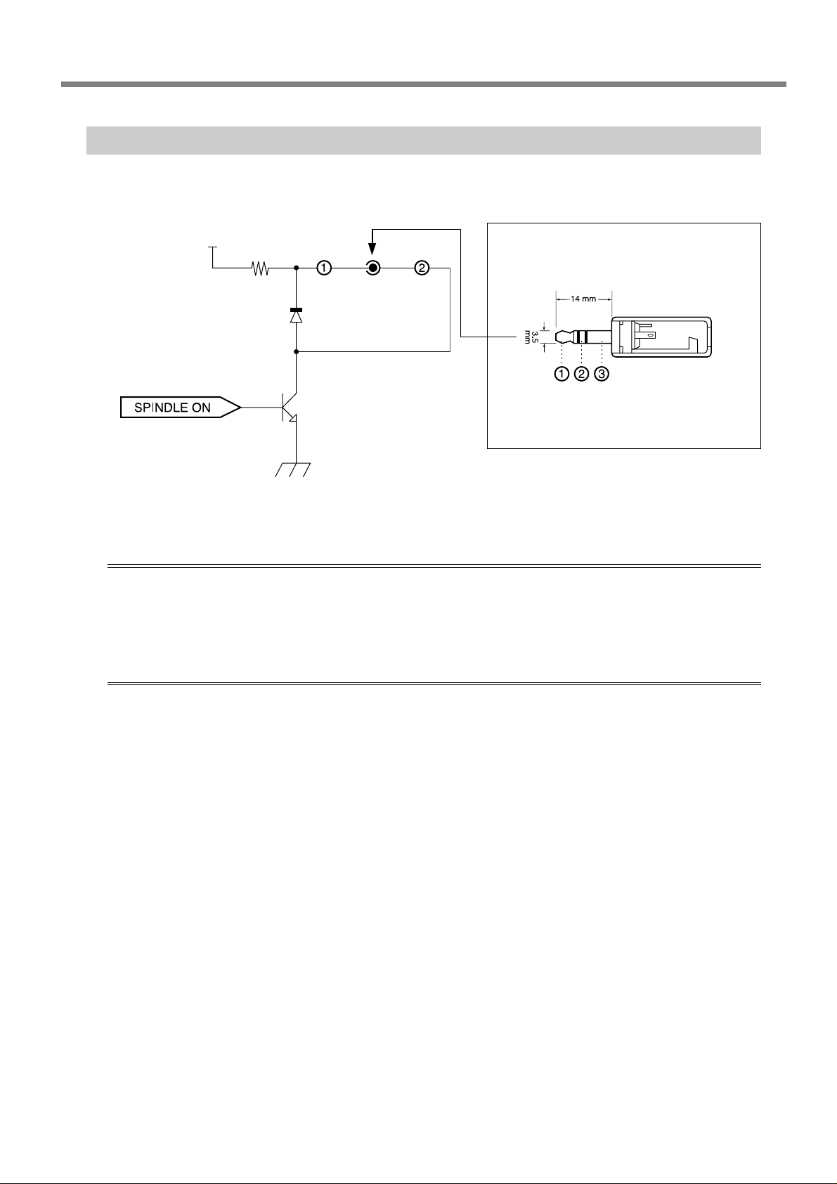
Expansion Connector Specification
5-4 Specifications
+24V
100Ω / 2W
Terminals
If (max) = 1A
Ic (max) = 150mA
This circuit is activated when the spindle motor is in operation.
About expansion connector specification
➢
Use within the rated range shown above.
➢
Do not apply voltage greater than 24 V to the terminal.
➢
Do not short the terminal to ground.
Compatible plug
Use only a triple-contact plug of the
size described above.
About compatible plug
Do not use terminal ➂. Use only terminals ➀ and ➁.
No responsible is assumed for effects to which any equipment connected to this external output connector is
subjected.
No responsible is assumed for malfunction when using any equipment connected to this external output connector is subjected.
Chapter 5 Appendix
47
Page 50

48
Page 51

Page 52

Please read this agreement carefully before opening the sealed
package or the sealed disk package
Opening the sealed package or sealed disk package implies your acceptance of the terms and conditions of this agreement.
Roland License Agreement
Roland DG Corporation ("Roland") grants you a non-assignable and non-exclusive right to use the COMPUTER
PROGRAMS in this package ("Software") under this agreement with the following terms and conditions.
1. Coming into Force This agreement comes into force when you purchase and open the sealed package
or sealed disk package.
The effective date of this agreement is the date when you open the sealed package
or sealed disk package.
2. Property Copyright and property of this Software, logo, name, manual and all literature for
this Software belong to Roland and its licenser.
The followings are prohibited :
(1) Unauthorized copying the Software or any of its support file, program module
or literature.
(2) Reverse engineering, disassembling, decompiling or any other attempt to
discover the source code of the Software.
3. Bounds of License Roland does not grant you to sub-license, rent, assign or transfer the right granted
under this agreement nor the Software itself (including the accompanying items)
to any third party.
You may not provide use of the Software through time-sharing service and/or
network system to any third party who is not individually licensed to use this
Software.
You may use the Software by one person with using a single computer in which
the Software is installed.
4. Reproduction You may make one copy of the Software only for back-up purpose. The property
of the copied Software belongs to Roland.
You may install the Software into the hard disk of a single computer.
5. Cancellation Roland retains the right to terminate this agreement without notice immediately
when any of followings occurs :
(1) When you violate any article of this agreement.
(2) When you make any serious breach of faith regarding this agreement.
6. Limitations on Liability Roland may change the specifications of this Software or its material without
notice.
Roland shall not be liable for any damage that may caused by the use of the
Software or by exercise of the right licensed by this agreement.
7. Governing Law This agreement is governed by the laws of Japan, and the parties shall submit to
the exclusive jurisdiction of the Japanese Court.
R1-041018
 Loading...