

Owner’s Manual
DCAC
AC & BATTERY
POWERED
FET

Thank you, and congratulations on your choice of the BOSS ML-2 Metal Core.
Before using this unit, carefully read the sections entitled: “USING THE UNIT SAFELY” and
“IMPORTANT NOTES” (supplied on a separate sheet). These sections provide important information concerning the proper operation of the unit.
Additionally, in order to feel assured that you have gained a good understanding of every feature provided by your new unit, this manual should be read in its entirety. The manual should
be saved and kept on hand as a convenient reference.
A battery is supplied with the unit. The life of this battery may be limited, however, since
its primary purpose is to enable testing.
Copyright © 2006 BOSS CORPORATION
All rights reserved. No part of this publication may be reproduced in any form without the
written permission of BOSS CORPORATION.
2

Main Features
●
The ML-2 produces a heavy distortion with a bold attack, making it ideal for massivesounding death-metal riffs.
●
The LOW control produces a deep, low sound, even if you don't use extreme downtuning.
●
The HIGH control lets you create guitar-riff sounds with lots of edge (attack) and a crisp
high end.
3
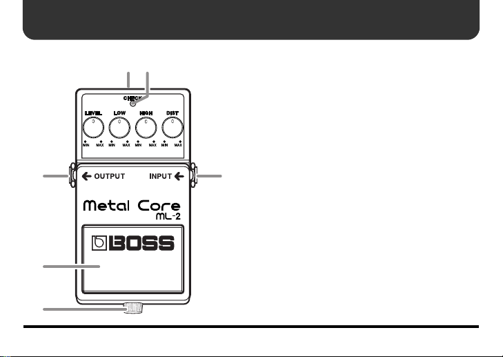
Panel Descriptions
fig.ML-2-name1.eps
12
3 6
4
5
4
1. AC Adaptor Jack
This jack accepts the connection of an AC
adaptor (optionally available BOSS PSA-series). By using an AC adaptor, you can play
without being concerned about how much
battery power you have left.
* Use only the specified AC adaptor (PSA-
series), and make sure the line voltage at the
installation matches the input voltage specified
on the AC adaptor's body. Other AC adaptors
may use a different polarity, or be designed for
a different voltage, so their use could result in
damage, malfunction, or electric shock.
* If the AC adaptor is connected while power is
on, the power supply is drawn from the AC
adaptor.
* If there is a battery in the unit while an AC
adaptor is being used, the ML-2 will switch
over to battery-powered operation should the

Panel Descriptions
line voltage be interrupted due to a power
blackout or power cord disconnection.
2. CHECK Indicator
This indicator shows whether the effect is on
or off, and also doubles as the battery check
indicator. The indicator lights when the effect is on.
* If you're powering the unit with a battery
and the CHECK indicator goes dim—or
doesn't light at all—when you try to turn the
effect on, the battery is near depletion and
should be replaced. For instructions on
changing the battery, refer to “Changing the
Battery” (p. 11).
* The CHECK indicator shows whether the
effect is being applied or not. It does not
indicate whether the power to the device
is on or not.
3. OUTPUT Jack
Connect this jack to the input of a guitar amp
or another effects processor.
4. Pedal Switch
This switch turns the effect on/off.
5. Thumbscrew
When this screw is loosened, the pedal will
open, allowing you to change the battery.
* For instructions on changing the battery,
refer to “Changing the Battery” (p. 11).
6. INPUT Jack
This jack accepts signals coming from a guitar or other musical instrument, or another
effects unit.
* The INPUT jack doubles as power switch.
5
Panel Descriptions
Power to the unit is turned on when you plug
into the INPUT jack; the power is turned off
when the cable is unplugged. When not using
the effects unit, be sure to disconnect the plug
from the INPUT jack.
fig.ML-2-name2.eps
87910
HIGH
LOW
DIST
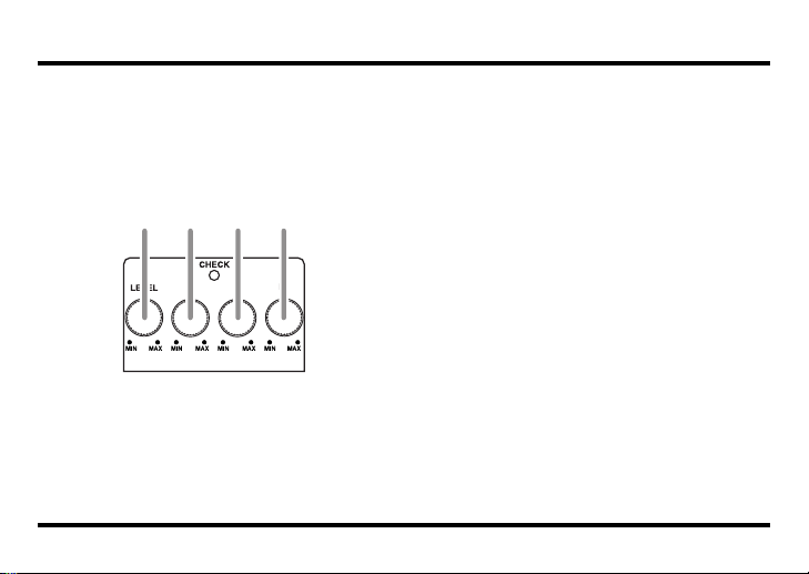
7. LEVEL Knob
This knob controls the volume the effect
sound.
6
8. LOW Knob
This knob controls the tone of the effect at
lower frequencies. Tuning the knob clockwise
boosts the lower frequencies, while tuning it
counterclockwise cuts the lower frequencies.
9. HIGH Knob
This knob controls the tone of the effect at
higher frequencies. Tuning the knob clockwise boosts the higher frequencies, emphasizing the picking attack. Tuning the knob
counterclockwise cuts the higher frequencies, producing a tone in which the low-frequency sounds are more prominent.
10. DIST Knob
This knob controls the amount of distortion
applied to the sound. Tuning the knob clockwise boosts the distortion effect.

Connections
* Inserting a connecting plug into the INPUT jack
turns on the power to the unit.
* Raise the amp volume only after turning on the
power to all connected devices.
* The use of an AC adaptor is recommended as the
unit’s power consumption is relatively high. Should
you prefer to use a battery, please use the alkaline
type.
* To prevent malfunction and/or damage to speakers
or other devices, always turn down the volume, and
turn off the power on all devices before making any
connections.
* If there is a batteries in the unit while an AC
adaptor is being used, normal operation will
continue should the line voltage be interrupted due
to power blackout or power cord disconnection.
* Some connection cables contain resistors. When
connection cables with resistors are used, the sound
level to be extremely low, or impossible to hear. For
A NOTE About Placement
BOSS Compact Pedals have a non-slip rubber pad attached to its bottom cover. Depending on the material and temperature of the surface on which you place the Compact Pedal, the rubber pad may discolor
or mar the surface. You can place a piece of felt or cloth under the unit to prevent this from happening.
If you do so, make sure the unit will not slip or move accidently during use.
information on cable specifications, contact the
manufacturer of the cable.
* Once the connections have been completed, turn on
power to your various devices in the order specified.
By turning on devices in the wrong order, you risk
causing malfunction and/or damage to speakers and
other devices.
When powering up:
Turn on the power to your guitar amp last.
When powering down:
Turn off the power to your guitar amp first.
* Always make sure to have the volume level turned
down before switching on power. Even with the
volume all the way down, you may still hear some
sound when the power is switched on, but this is
normal, and does not indicate a malfunction.
* When operating on battery power only, the CHECK
indicator will become dim when battery power gets
too low. Replace the battery as soon as possible.
7

Connections
fig.Connect-ML-2e.eps
AC Adaptor
BOSS PSA-series
(sold separately)
OUT 9V DC/200 mA
Electric Guitar
Guitar Amp
* This unit is equipped with a protection circuit. A brief interval (a few seconds) after power up is
required before the unit will operate normally.
8

Operating the Unit
fig.ML-2-operation1.eps
1.
After you have made the
necessary (p. 7, 8) connections, set the panel knobs
as shown in the illustration.
fig.ML-2-operation2.eps
2.
Depress the pedal switch
to turn the effect on. (The
CHECK indicator lights
when the effect is on.)
3.
Adjust the amount of distortion with the DIST
knob.
fig.ML-2-operation3.eps
4.
Adjust the amount of
high-frequency sound
with the HIGH knob.
9

Operating the Unit
fig.ML-2-operation4.eps
5.
Adjust the amount of
low-frequency sound
with the LOW knob.
10
fig.ML-2-operation5.eps
6.
Adjust the output volume
with the LEVEL knob.
Normally, you should adjust the LEVEL knob so
there's no difference in
the volume when switching the effect on and off.

Changing the Battery
When the indicator goes dim or no longer
lights while the effect is on, it means that the
battery is nearly dead and must be replaced.
Replace the battery following the steps below.
* The use of an AC adaptor is recommended as the
unit’s power consumption is relatively high. Should
you prefer to use a battery, please use the alkaline type.
fig.replace-battery.eps
Thumbscrew
Battery Snap
Cord
Battery
Snap
9V Battery
Battery Housing
Pedal
Spring Base
Coil Spring
Guide Bush
Hole
1.
Loosen the thumbscrew at the front of
the pedal, and then lift the pedal
upwards to open the unit.
* The thumbscrew can be left in the pedal while
changing the battery.
2.
Remove the old battery from the battery
housing, and remove the snap cord connected to it.
3.
Connect the snap cord to the new battery,
and place the battery inside the battery
housing.
* Be sure to carefully observe the battery’s polarity (+
versus -).
4.
Slip the coil spring onto the spring base
on the back of the pedal, and then close
the pedal.
* Carefully avoid getting the snap cord caught in the
pedal, coil spring, and battery housing.
5.
Finally, insert the thumbscrew into the
guide bush hole and fasten it securely.
11

Troubleshooting
The power won’t come on /
the CHECK indicator doesn’t light
●
Is the specified adaptor (PSA-series, sold
separately) properly connected?
Check the AC adaptor connection (p. 7, 8).
* Never use any AC adapter other than one
specified for use with the ML-2.
●
Is the battery low or dead?
Replace it with a new battery (p. 11).
* The battery that is supplied with the unit is for
temporary use, intended primarily for testing
the pedal’s operation.
* The use of an AC adaptor is recommended as the
unit’s power consumption is relatively high.
Should you prefer to use a battery, please use the
alkaline type.
* To prevent unnecessary battery consumption, be
sure to disconnect the plug from the INPUT jack
when not using the effects unit (p. 5).
●
Is your guitar properly connected to the INPUT jack?
Check the connection once more (p. 7, 8).
12
* A cable must be connected to the INPUT jack to
allow the effect to be turned on.
* If a cable is connected but no power is supplied
to the unit (either from a battery or an AC
adaptor), the CHECK indicator will not light
when you try to turn the effect on.
No sound / low volume
●
Is your instrument properly connected to
the ML-2?
Check the connection once more (p. 7, 8).
●
Is the LEVEL knob set too low?
The further counterclockwise you turn the
LEVEL knob, the more the volume is reduced when the effect is on. Turn the LEVEL
knob clockwise to increase the volume.
●
Is the volume turned down on any guitar
amp or effects device you have connected?
Check the settings of the connected device.
●
Is the battery low or dead?
Replace it with a new battery (p. 11).

Setting Samples
Heavy solid riff
fig.ML-2-sample1.eps
Blast beat metal
fig.ML-2-sample1.eps
Extreme downtuning
fig.ML-2-sample1.eps
Gothenburg sound
fig.ML-2-sample1.eps
13

Setting Memo
fig.setting-memo.eps
fig.setting-memo.eps
14
fig.setting-memo.eps
fig.setting-memo.eps

Specifications
ML-2: Metal Core
Nominal Input Level........................ -20 dBu
Input Impedance............................... 1 M
Nominal Output Level..................... -20 dBu
Output Impedance ........................... 1 k
Recommended Load Impedance.... 10 kΩ or greater
Controls.............................................. Pedal switch, LEVEL knob, LOW knob, HIGH knob,
Indicators ...........................................CHECK indicator (for effect on/off status and battery
Connectors......................................... INPUT jack, OUTPUT jack, AC Adaptor jack (DC 9 V)
Power Supply.................................... DC 9 V: Dry battery 6F22 (9 V) type (carbon)/
Current Draw .................................... 36 mA (DC 9 V)
Ω
Ω
DIST knob
check)
Dry battery 6LR61 (9 V) type (alkaline)
AC adaptor (PSA-series: optional)
* Expected battery life under continuous use:
Carbon: 3 hours, Alkaline: 10 hours
These figures will vary depending on the actual conditions of use.
15

Specifications
Dimensions........................................ 73 (W) x 129 (D) x 59 (H) mm
2-7/8 (W) x 5-1/8 (D) x 2-3/8 (H) inches
Weight ................................................ 440 g /1 lb (including battery)
Accessories......................................... Owner’s manual, leaflet (“USING THE UNIT SAFELY,”
“IMPORTANT NOTES,” and “Information”),
dry battery 6LR61 (9 V) type (alkaline)
* The battery that is supplied with the unit is for temporary
use, intended primarily for testing the unit's operation.
We suggest replacing this battery with an alkaline dry cell.
Option ................................................ AC adaptor (PSA-series)
* 0 dBu = 0.775 Vrms
* In the interest of product improvement, the specifications and/or appearance of this unit are subject
to change without prior notice.
16

MEMO
17

MEMO
18

For EU Countries
This product complies with the requirements of European Directive 89/336/EEC.
For the USA
FEDERAL COMMUNICATIONS COMMISSION
RADIO FREQUENCY INTERFERENCE STATEMENT
This equipment has been tested and found to comply with the limits for a Class B digital device, pursuant to Part 15 of the
FCC Rules. These limits are designed to provide reasonable protection against harmful interference in a residential
installation. This equipment generates, uses, and can radiate radio frequency energy and, if not installed and used in
accordance with the instructions, may cause harmful interference to radio communications. However, there is no guarantee
that interference will not occur in a particular installation. If this equipment does cause harmful interference to radio or
television reception, which can be determined by turning the equipment off and on, the user is encouraged to try to correct the
interference by one or more of the following measures:
– Reorient or relocate the receiving antenna.
– Increase the separation between the equipment and receiver.
– Connect the equipment into an outlet on a circuit different from that to which the receiver is connected.
– Consult the dealer or an experienced radio/TV technician for help.
This device complies with Part 15 of the FCC Rules. Operation is subject to the following two conditions:
(1) This device may not cause harmful interference, and
(2) This device must accept any interference received, including interference that may cause undesired operation.
Unauthorized changes or modification to this system can void the users authority to operate this equipment.
This equipment requires shielded interface cables in order to meet FCC class B Limit.
For Canada
NOTICE
This Class B digital apparatus meets all requirements of the Canadian Interference-Causing Equipment Regulations.
Cet appareil numérique de la classe B respecte toutes les exigences du Règlement sur le matériel brouilleur du Canada.
AVIS

G6027118R0
 Loading...