

Page 1
Technology that simulates existing physical
structures, materials, and the like using
different, virtual means is called “modeling
technology.”
COSM (Composite Object Sound Modeling) is
a technical innovation from Roland that
combines a number of such sound-modeling
technologies to create even newer sounds.
Owner's Manual
201a
Before using this unit, carefully read the sections entitled: “USING THE UNIT SAFELY” (p. E-18) and “Important Notes” (p. E-19). These
sections provide important information concerning the proper operation of the unit. Additionally, in order to feel assured that you have
gained a good grasp of every feature provided by your new unit, Owner’s Manual should be read in its entirety. The manual should be
saved and kept on hand as a convenient reference.
202
Copyright © 2008 BOSS CORPORATION
All rights reserved. No part of this publication may be reproduced in any form without the written permission of BOSS CORPORATION.
220
All product names mentioned in this document are trademarks or registered trademarks of their respective owners.
Creating Sounds................................................................. E-2
Printing Conventions and
icons in This Manual
Text or numerals
enclosed in
square brackets [ ]
(p. E-**)
Indicate buttons.
[WRITE] WRITE button
Indicates information that
you should be aware of when
using the ME-70.
Indicates supplementary
information about an
operation.
Indicates information about a
convenient operation.
Indicates a reference page.
Using the Effects................................................................. E-4
COMP/FX (Compressor/Effects) ........................................................................ E-4
OD/DS (Overdrive/Distortion)............................................................................ E-5
MODULATION.......................................................................................................... E-6
DELAY ......................................................................................................................... E-7
PREAMP...................................................................................................................... E-8
NS (Noise Suppressor)........................................................................................... E-8
REVERB........................................................................................................................ E-9
PEDAL FX (Pedal Effects)...................................................................................... E-9
Saving/Calling Up and Using Tones (Memory Mode) ... E-10
Changing Between the Manual and Memory Modes .............................E-10
Saving Tones (Patch Write)...............................................................................E-10
Calling Up Tones (Patches) ...............................................................................E-11
Changing Tone Settings (Memory Edit Mode) ..........................................E-11
Español Português NederlandsItalianoFrançaisDeutschEnglish
Convenient Functions...................................................... E-12
Creating Tones with Ease (EZ Tone) ..............................................................E-12
Checking the Values of Controls.....................................................................E-12
Tuning the Guitar (Tuner)..................................................................................E-13
Using External Foot Switches...........................................................................E-13
Applying Effects in Time with the Song Tempo (Tap Tempo).............E-14
Phrase Loop Play...................................................................................................E-15
Making the Settings for Control Operation ................................................E-15
Restoring the Factory Settings (Factory Reset) ............. E-16
Adjusting the Expression Pedal ...................................... E-16
Appendices ....................................................................... E-17
USING THE UNIT SAFELY...............................................................................E-18
Important Notes ..............................................................................................E-19
*G6037008-01*
Page 2
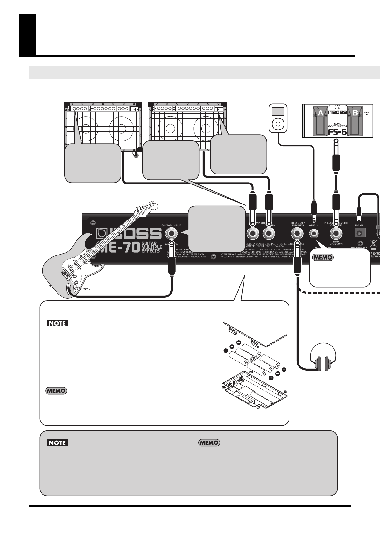
Stereo Headphones
Electric Guitar
Guitar Amp
Digital Audio
Player, etc.
Footswitch
(BOSS FS-6, etc.)
W
The battery compartment is located on the underside.
Insert the included batteries, taking care to orient them correctly.
Note when connecting the ME-70 to the other devices
Step Step
1
Step Step
2
Step Step
4
Step Step
3
Step
1
Step
2
Step
4
Step
3
Turn down the
volume all the way
on all equipment!
Connect the
equipment.
Insert the plug
to power up the
ME-70.
Switch on the
amp's power last!
You can mix stereo
audio from AUX IN
with the output.
The ME-70 has no built-in amp or speakers. To hear sounds,
you'll need to provide a guitar amplier, stereo headphones,
or other such equipment.
For mono output, connect the cable to just the L/MONO jack.
To send the output from the REC OUT/PHONES jack to a
recorder or the like, use a special cable (PCS-31L; sold separately).
If you use an ordinary guitar cable, only the left-channel audio is
output.
When turning the unit upside-down, get a bunch of newspapers or magazines, and place them under
the four corners or at both ends to prevent damage to the buttons and controls. Also, you should try to
orient the unit so no buttons or controls get damaged.
When turning the unit upside-down, handle with care to avoid dropping it, or allowing it to fall or tip over.
Carefully follow the installation instructions for batteries, and make sure you observe the correct polarity.
Avoid using new batteries together with used ones. In addition, avoid mixing dierent types of batteries.
Remove the batteries whenever the unit is to remain unused for an extended period of time.
If a battery has leaked, use a soft piece of cloth or paper towel to wipe all remnants of the discharge
from the battery compartment. Then install new batteries. To avoid inammation of the skin, make sure
that none of the battery discharge gets onto your hands or skin. Exercise the utmost caution so that
none of the discharge gets near your eyes. Immediately rinse the aected area with running water if
any of the discharge has entered the eyes.
Never keep batteries together with metallic objects such as ballpoint pens, necklaces, hairpins, etc.
Once the connections have been completed, turn on power to your various devices in
the order specied. By turning on devices in the wrong order, you risk causing malfunction
and/or damage to speakers and other devices.
To prevent malfunction and/or damage to speakers or other devices, always turn down the
volume, and turn o the power on all devices before making any connections.
Raise the amp volume only after turning on the power to all connected devices.
This unit is equipped with a protection circuit. A brief interval (a few seconds) after power up is
required before the unit will operate normally.
When connection cables with resistors are used, the volume level of equipment connected to
the inputs (AUX IN) may be low. If this happens, use connection cables that do not contain resistors.
Expected battery life under continuous use: Carbon: 5 hours, Alkaline: 13 hours
These gures will vary depending on the actual conditions of use.
When operating on battery power only, the unit's indicator will become dim when battery power gets too low.
Replace the battery as soon as possible.
We recommend that you keep batteries installed in the unit even when you're powering it with the AC adaptor.
That way, you’ll be able to continue a performance even if the cord of the AC adaptor gets accidently disconnected from the unit.
To
un
avo
the
illu
Creating Sounds
AUX INGUITAR
Making the Connections and Turning the Power On
E-2
Page 3
Digital Recorder, etc.
PCS-31L cable
(Sold separately)
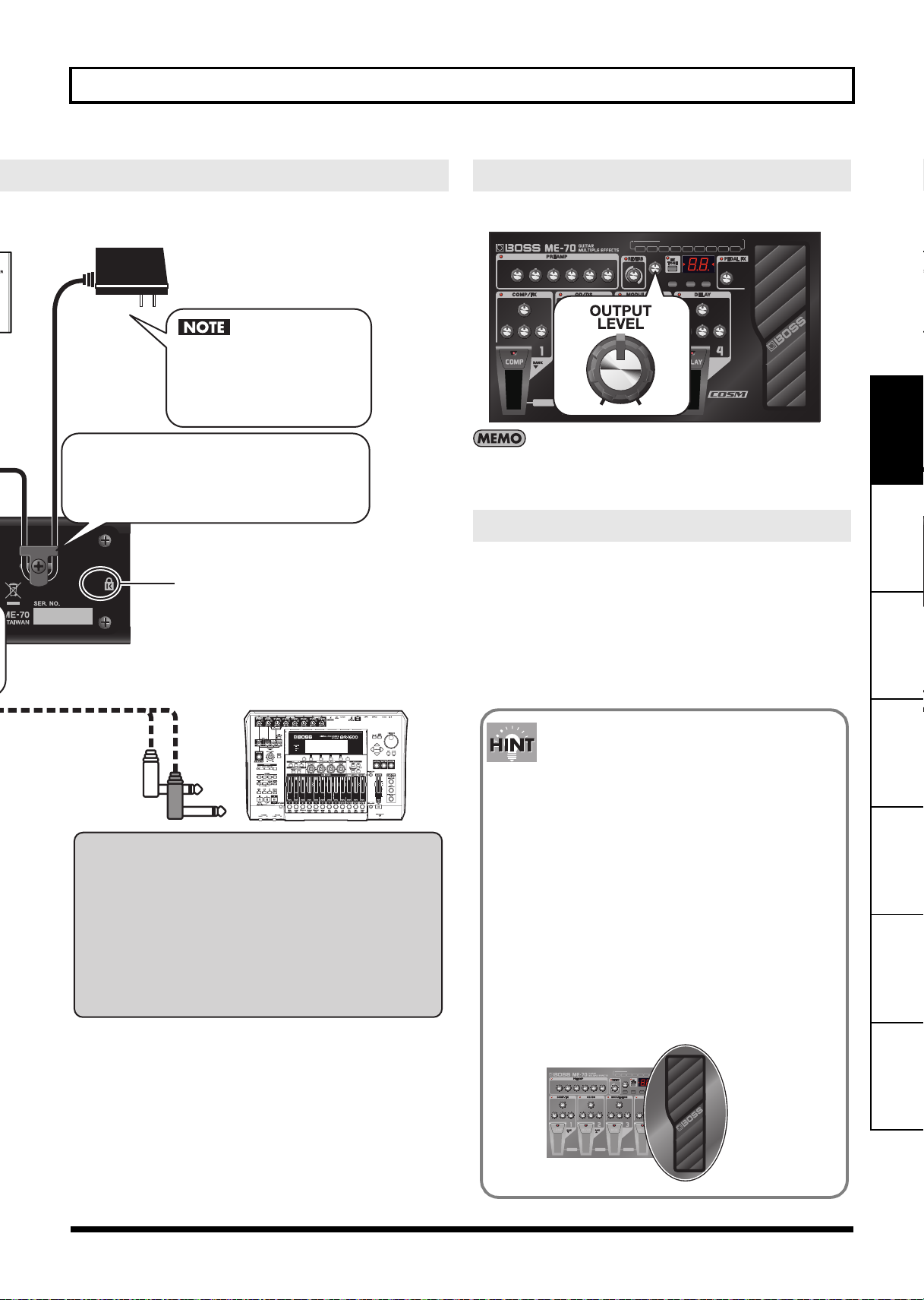
AC Adaptor PSA series
(sold separately)
White (L)
Red (R)
Be sure to use a PSA
series adaptor. The use
of any other adaptor
may cause malfunction.
Inserting a plug into the REC OUT/PHONES jack
automatically activates the built-in guitar-amp
simulator, enabling you to enjoy impressive guitar
sound even with headphones.
The same eect is applied to Gt. AMP OUTPUT at
this time, too.
When you're performing using a guitar amp
connected to Gt. AMP OUTPUT, disconnect the
plug from the REC OUT/PHONES jack.
To prevent the inadvertent disruption of power to your
unit (should the plug be pulled out accidentally), and to
avoid applying undue stress to the AC adaptor jack, anchor
the power cord using the cord hook, as shown in the
illustration.
Connect a commercially available
anti-theft security cable here.
http://www.kensington.com/
INPUTPHONES POWER ONREC OUT
Should you encounter unexpected results,
such as no sound being produced, check the
following.
• Are connections to other devices correctly made?
Check the connections once more.
• Is the volume turned down?
Check the volume levels on any connected amp or mixer.
• Can you hear sound through the headphones when
headphones are connected?
If you can hear sounds, it may be that there is a short in the cable
used to connect the amp or other device, or perhaps a mistake in
an external device’s settings. Check the connecting cables and
external devices once more.
• Has the level been lowered with the expression pedal?
Sounds are not output when the toe of the expression
pedal is in the raised position while the pedal is set to
function as a volume pedal (p. E-9).
Expression
Pedal
Creating Sounds
Adjusting the Volume
1. Adjust the OUTPUT LEVEL knob.
Raising the OUTPUT LEVEL knob too much may result in sound distortion.
When the OUTPUT LEVEL knob is centered and all effects are off, input and
output are at the same level.
Turning Off the Power
1. Turn down the volume all the way on all equipment
(this unit, the amplifier, and everything else).
2. Switch off the amp and other connected devices.
3. Unplug the guitar or other instrument connected to
the INPUT jack on the ME-70.
The power to the ME-70 is switched off.
OUTPUT
guitar-amp simulatorGt.AMP
Español Português NederlandsItalianoFrançaisDeutschEnglish
E-3
Page 4
Using the Effects
All product names mentioned in this document are trademarks or registered trademarks of their respective owners.
Those companies are not affiliated with BOSS and have not licensed or authorized BOSS's ME-70. Their marks are used solely to identify the
equipment whose sound is simulated by BOSS's ME-70.
SENS
TONE
PEAK
SENS
ATT AC K
LEVEL
SENS
TONE
LEVEL
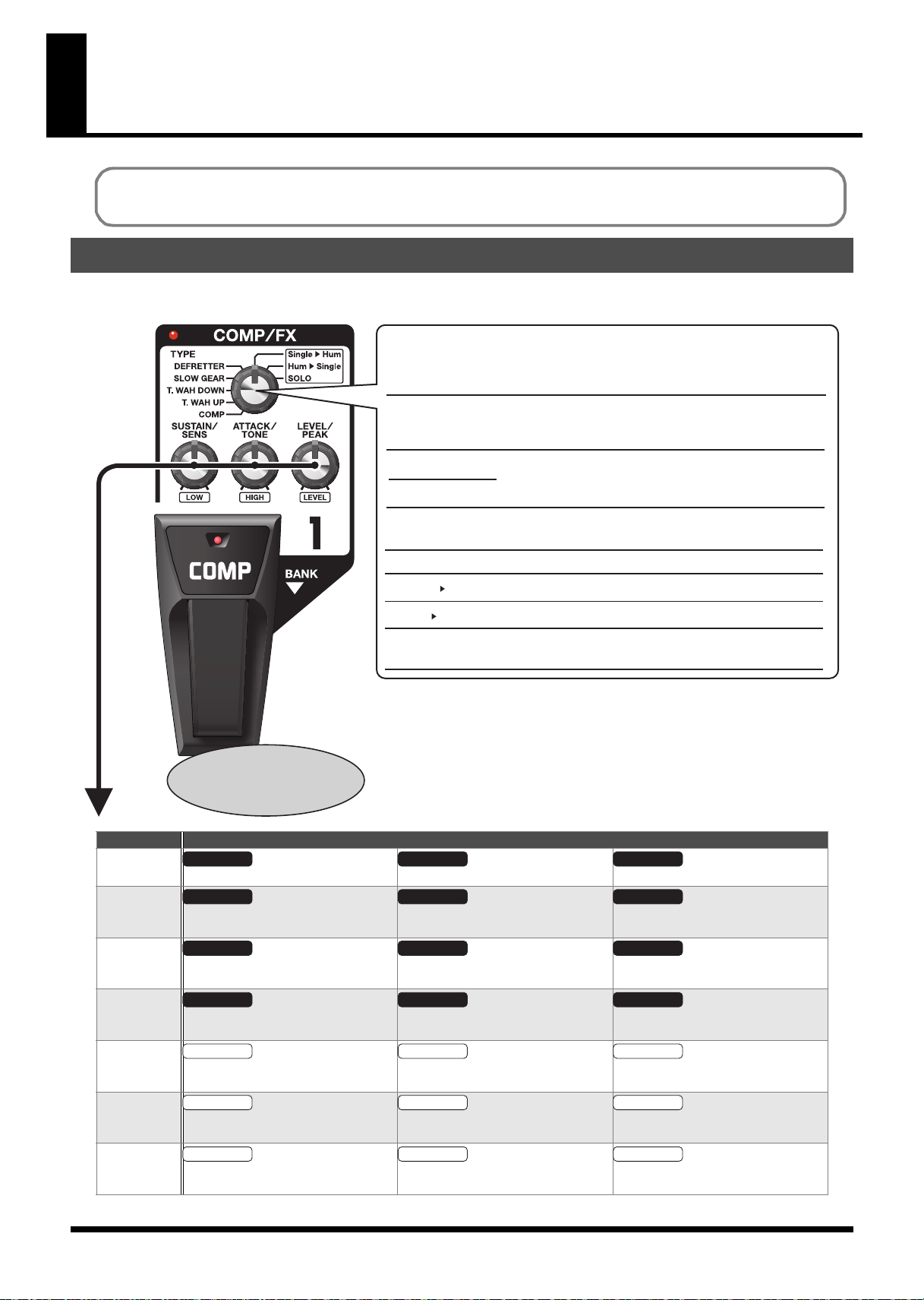
COMP/FX (Compressor/Effects)
You can select from among a wide variety of original effects, such as those that equalize the volume levels, or extend the sound without
distorting it (sustain).
fig.0140
TYPE knob
Use this to choose the type of compressor or eect.
COMP Pedal
This switches the eect
on and o.
TYPE What the controls do
COMP
SUSTAIN ATT AC K
This sets the sustain for the sound. This sets the attack (onset) of the sound. This sets the volume level of the effect.
1: COMP
2: T.WAH UP
3: T.WAH DOWN
4: SLOW GEAR
5: DEFRETTER
6: Single Hum
7: Hum Single
8: SOLO
This produces an eect that sustains the sound without
distortion. It also works as a limiter to suppress loud peaks in
the input signal.
This produces a wah eect matched to the intensity of picking.
This removes the attack portion of the signal to create
violin-like sounds.
This simulates a fretless guitar.
This changes a single-coil sound to a humbucker sound.
This changes a humbucker sound to a single-coil sound.
This produces the optimal sound for solo playing in
combination with OD/DS or PREAMP.
LEVEL
T.WAH UP/
T.WAH DOWN
SLOW GEAR
DEFRETTER
Single>Hum
Hum>Single
SOLO
E-4
This sets the sensitivity of response to the
input sound.
This sets the sensitivity of response to the
input sound.
This sets the sensitivity of response to the
input sound.
LOW HIGH LEVEL
This adjusts the tone of the low frequency range.
LOW HIGH LEVEL
This adjusts the tone of the low frequency range.
LOW HIGH LEVEL
This adjusts the tone of the low frequency range.
This sets the tone (brightness) of the wah. This sets the intensity of the wah sound.
Adjusts the time needed for the volume
to reach its maximum.
This sets the tone. This sets the volume level of the effect.
This adjusts the tone of the high frequency range.
This adjusts the tone of the high frequency range.
This adjusts the tone of the high frequency range.
This sets the volume level of the effect.
This sets the volume level of the effect.
This sets the volume level of the effect.
This sets the volume level of the effect.
Page 5
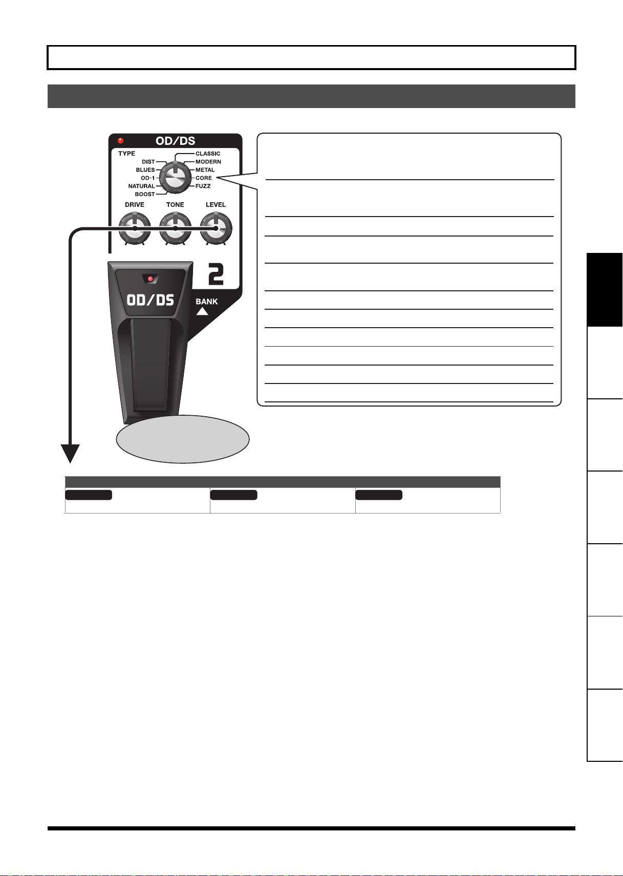
OD/DS (Overdrive/Distortion)
TYPE knob
Use this to choose the type of overdrive or distortion.
1: BOOST
2: NATURAL
3: OD-1
4: BLUES
5: DIST
6: CLASSIC
7: MODERN
8: METAL
9: CORE
10: FUZZ
This is a gain booster. It works well for creating distortion with a
COSM preamp, or for creating punchy clean tones when used
alone.
This is an overdrive sound with natural-sounding distortion.
This is the sound of the BOSS OD-1. It produces sweet,
mild distortion.
This is a unique overdrive that faithfully reproduces the
nuances of picking.
This is a sharp distortion with rich sustain.
This is the sound of a vintage stack-type amp.
This is the sound of a large high-gain amp.
This is a distortion that emphasizes the midrange.
This is a distortion that cuts the midrange.
This is a distortion that is distinctively rough and heavy.
OD/DS pedal
This switches the eect
on and o.
DRIVE
TONE
LEVEL
These effects add distinctive distortion or sustain.
fig.0140
Using the Effects
What the controls do
Sets the intensity of the distortion. Sets the brightness of the sound. Sets the volume level for OD/DS.
Español Português NederlandsItalianoFrançaisDeutschEnglish
E-5
Page 6
Using the Effects
RATE
DEPTH
E. LEVEL
D. LEVEL
E. LEVEL
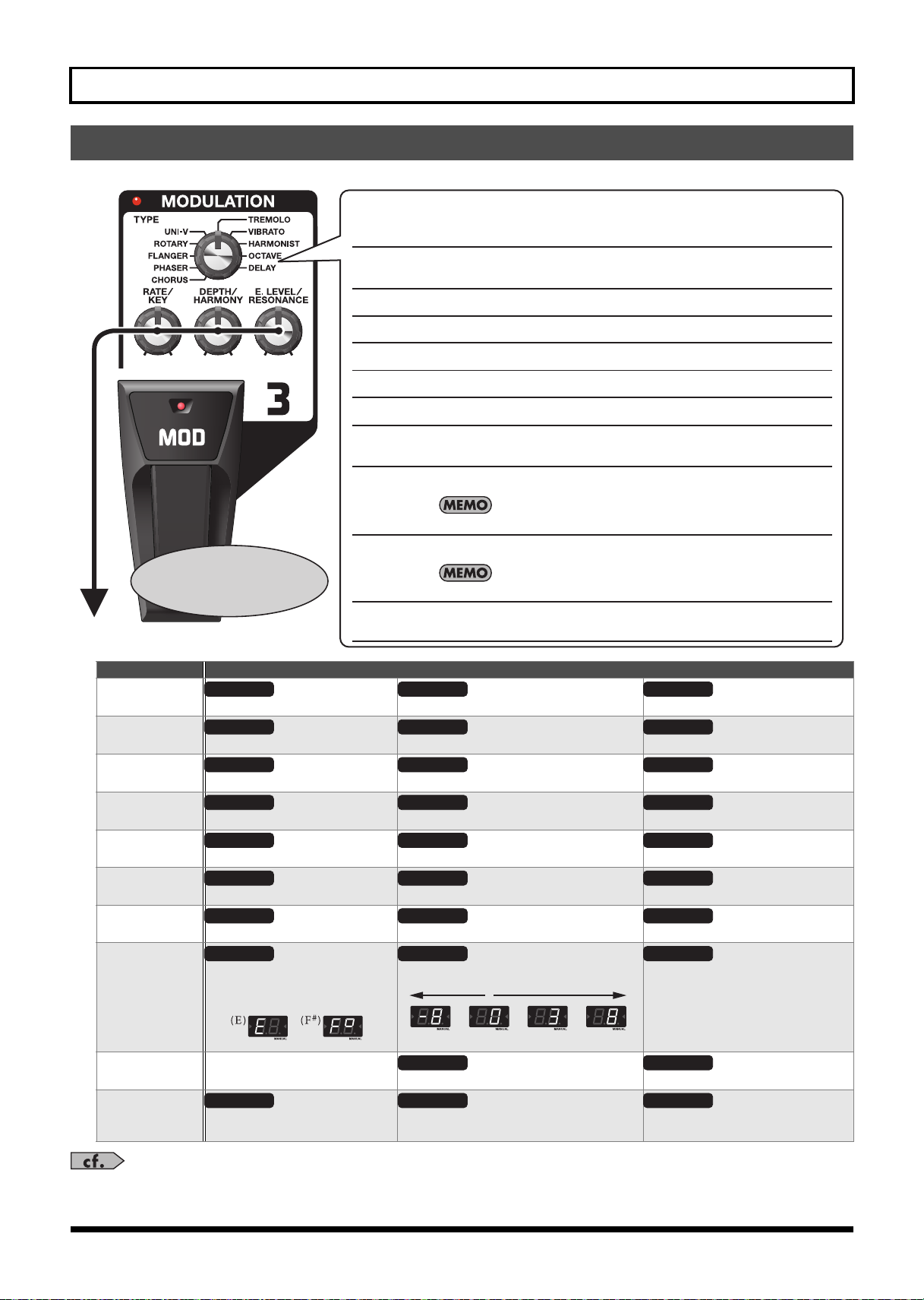
MODULATION
These effects broaden, modulate, and/or pitch shift the sound.
fig.0140
TYPE knob
Use this to choose the type of modulation.
1: CHORUS
This eect adds subtle wavering to transform the tone into one that is
broader, thicker, and more beautiful.
MOD Pedal
This switches the eect
on and o.
TYPE What the controls do
CHORUS
PHASER
FLANGER
ROTARY
RATE DEPTH E. LEVEL
This sets the speed of the effect. This sets the richness of the effect. This sets the volume level of the effect.
RATE DEPTH
This sets the speed of the effect. This sets the richness of the effect. This sets the intensity of the effect.
RATE DEPTH
This sets the speed of the effect. This sets the richness of the effect. This sets the intensity of the effect.
RATE DEPTH E. LEVEL
This sets the speed of the effect. This sets the richness of the effect. This sets the volume level of the effect.
2: PHASER
3: FLANGER
4: ROTARY
5: UNI-V
6: TREMOLO
7: VIBRATO
8: HARMONIST
9: OCTAVE
10: DELAY
This eect creates a sweeping, phase-shifted sound.
This creates a modulation eect like the rising and falling sound of a jet engine.
This eect produces the sound of rotating speakers.
This models the Uni-Vibe, an eect that's part of the rock sound of the 1960s.
This produces a retro eect through cyclical changes in the volume level.
This produces an intense vibrato eect unobtainable with normal guitar
playing.
This creates harmonies reminiscent of twin guitars.
Play only single notes when using the harmonist eect.
This imparts thickness by adding sound an octave lower.
Play only single notes when using the octave eect.
This delays the sound to produce an echo-like eect. At delay times of
100 to 990 ms (milliseconds), you can use it as a secondary delay.
RESONANCE
RESONANCE
UNI-V
TREMOLO
VIBRATO
HARMONIST
OCTAVE
DELAY
This sets the speed of the effect. This sets the richness of the effect. This sets the volume level of the effect.
RATE DEPTH E. LEVEL
This sets the speed of the effect. This sets the richness of the effect. This sets the volume level of the effect.
RATE DEPTH E. LEVEL
This sets the speed of the effect. This sets the richness of the effect. This sets the volume level of the effect.
KEY
This sets the musical key of the song
HARMONY
This sets the pitch of the harmony. This sets the volume level of the effect.
being played.
Ex.
Detune +1 Octave3rd-1 Octave
—
This sets the volume level of the direct sound. This sets the volume level of the effect.
TIME
This sets the delay time (10 to 990
FEEDBACK
This set the number of repetitions for the delay. This sets the volume level of the effect.
ms), in steps of 10 ms.
You can control the RATE parameter using the expression pedal. For more information, read “Using Pedal FX” (p. E-9).
E-6
E. LEVEL
E. LEVEL
Page 7

DELAY
FEEDBACK
E. LEVEL
Ex.
120ms 990ms
TIME
FEEDBACK
E. LEVEL
Ex.
1200ms 6000ms
TIME
This delays the sound to produce an echo-like effect. It lets you add thickness and create complex sounds.
fig.0140
TYPE knob
Use this to choose the type of delay.
Using the Effects
DELAY pedal
This switches the eect
on and o.
TYPE What the controls do
TIME
1-99 ms
This sets the delay time in steps of 1 ms.
Ex.
2ms 99ms
1: 1-99ms
2: 100-990ms
3: 1000-6000ms
4: ANALOG
5: MODULATE
6: REVERSE
7: CHO + DELAY
8: MOMENTARY
9: TAP
10: PHRASE LOOP
In memory mode (p. E-10), MOMENTARY, TAP, and PHRASE LOOP pedal
operations use the number pedal for the currently selected patch.
This is a delay of 1 to 99 ms (milliseconds), which is ideal for a doubling
eect.
This delay has a delay time of 100 to 990 ms (milliseconds).
This is a delay of 1,000 to 6,000 ms (milliseconds), which is suited to
special eects.
This produces a mild analog delay sound.
This is a delay with a pleasant chorus-type eect added to the delay
repeats.
This produces the eect of playback in reverse.
This produces chorus and delay eects at the same time.
(The settings for chorus cannot be changed.)
Delay is activated only while the DELAY pedal is pressed.
This determines the delay time by using the pedal.
This lets you record a performance and play it back repeatedly.
This is useful for both live performances and practice sessions.
This sets the number of
This sets the volume level of the delay sound.
repetitions for the delay.
100-990 ms
1000-6000 ms
ANALOG
MODULATE
REVERSE
CHO + DELAY
This sets the delay time in steps of 10 ms.
This sets the delay time in steps of 100 ms.
TIME
Ex.
120ms 990ms
This sets the delay time (10 to 990 ms), in steps o f 10 ms.
This sets the number of
repetitions for the delay.
FEEDBACK
This sets the number of
repetitions for the delay.
FEEDBACK
This sets the number of
repetitions for the delay.
This sets the volume level of the delay sound.
This sets the volume level of the delay sound.
This sets the volume level of the effect.
MOMENTARY
TAP
Ex.
This sets the beat for the delay sound.
“Applying Effects in Time with the Song Tempo (Tap
Tempo)” (p. E-14)
FEEDBACK
This sets the number of
repetitions for the delay.
This sets the volume level of the delay sound.
— —
This sets the volume level of the phrase loop.
PHRASE LOOP
You can control the E. LEVEL para meter using the ex pression pedal. For more information , read “Using Pedal FX” (p. E-9).
E. LEVEL
E. LEVEL
When TYPE is set to REVERSE, this adjusts the
balance of direct and effect sound.
E. LEVEL
E. LEVEL
“Phrase Loop Play” (p. E-15)
Español Português NederlandsItalianoFrançaisDeutschEnglish
E-7
Page 8

Using the Effects
T
LEVEL
T
fig.0160
PREAMP
This models preamp response. You can also use it as an equalizer.
fig.0140
TYPE knob
Use this to choose the type of preamp.
0: OFF
1: EQ
2: CLEAN
3: COMBO
4: TWEED
5: STACK
6: LEAD STK
7: R-FIER
TYPE What the controls do
EQ
CLEAN
COMBO
TWEED
STACK
LEAD STK
R-FIER
This sets the
amount of distortion of the preamp.
hese adjust the volume
of the respective EQ bands.
GAIN
This turns o preamp modeling.
This is a 4-band parametric equalizer.
This is a clean sound that is smooth and warm.
This is a crunch sound reminiscent of a VOX combo amp.
This is a crunch sound like that of a Fender Bassman.
This is a sound reminiscent of 1970s Marshall amps.
This is a high-gain lead sound.
This models a Mesa/Boogie Dual Rectier.
LOW
hese adjust the volume
of the respective EQ bands.
LOW-MID
BASS MIDDLE TREBLE
HIGH-MID
HIGH
This sets the overall volume level.
Frequency
LEVEL
This sets the overall volume level of the preamp.
Frequency
fig.0160
NS (Noise Suppressor)
This suppresses the noise and hum picked up by the guitar's pickup.
NS THRES (Noise Suppressor Threshold)
fig.0140
This adjusts the effect in response to the level of noise. A value of 0 switches off the noise suppressor.
Setting this higher than necessary may cause no sound to be produced when the guitar is played at low volume.
E-8
Page 9

REVERB
Using Pedal FX
Firmly pressing the toe of the expression pedal (while putting some weight into it) switches the
function of the expression pedal.
PEDAL FX Indicator Explanation
Dark Functions as VOLUME (volume pedal).
Lit Functions as the effect selected using the PEDAL FX knob.
PEDAL FX
Indicator
This adds lingering reverberations to the sound.
This adjusts the type of reverb and the size of the eect.
Using the Effects
ROOM
HALL
Display example
ROOM 12 HALL 49
This simulates the reverberations inside a room (setting value: 0. through 49.)
This simulates the reverberations inside a hall (setting value: 0. through 49.)
The dot indicates that
the eect is HALL reverb.
PEDAL FX (Pedal Effects)
This produces a variety of effects using the unit's expression pedal.
fig.0140
Use this to choose the type of PEDAL FX.
1: WAH
2: VOICE
3: +1 OCTAVE
4: -1 OCTAVE
5: MOD RATE
This is a wah eect.
This lets you create sounds that simulate a human voice.
This lets continuously vary the pitch up to one octave higher or lower than the
original sound.
Play single notes.
This lets you control the rate of the MODULATION eect.
The MODULATION eect's RATE knob determines the maximum value of the range controlled with the
expression pedal.
6: DELAY LEV
This lets you control delay level when you're using the DELAY eect.
The DELAY eect's E. LEVEL knob determines the maximum value of the range controlled with the
expression pedal.
Español Português NederlandsItalianoFrançaisDeutschEnglish
E-9
Page 10

Saving/Calling Up and Using Tones
1
When the unit is in Manual mode, the dot at the bottom right
of the display lights up. When the unit is in Memory mode, the
currently selected bank number is displayed.
Manual Mode Memory Mode
(User Bank 1)
Memory Mode
(Preset Bank 2)
(Memory Mode)
The ME- 70 has two p rimary operating modes: Manual mode and Memor y mode. In Manual mode, the tones ar e produced by the a ctual positions
of the front-panel knobs for the various effects. In contrast, Memory mode allows you to save tone settings and recall them for later use.
Patches and Banks
In Memory mode, a combination (or set) of effects together with a
group of parameter settings is called a “patch.”
A group of four patches is called a “bank,” and the respective
patches in a bank correspond to the number pedals.
The banks are organized into nine “user banks” that you can freely
read from or write to, and nine read-only “preset banks.”
In total, the ME-70 has 72 patches.
User Bank 1
Patch Patch Patch Patch
Patch Patch Patch Patch
Patch Patch Patch Patch
You can read from
and write to these
without restriction.
Changing Between the Manual and Memory Modes
User Bank 9
User Bank 3
User Bank 2
Patch Patch Patch Patch
Preset Bank 9
Preset Bank 3
Preset Bank 2
Patch Patch Patch Patch
Preset Bank 1
Patch Patch Patch Patch
Patch Patch Patch Patch
Patch Patch Patch Patch
(Writing to them is not possible.)
Number Pedals
These are read-only.
1. Press number pedals 3 and 4 at the same time.
2. Each press switches the ME-70 between Manual
mode and Memory mode.
Saving Tones (Patch Write)
This saves the control settings in a patch.
You can perform patch-write operations either in Manual mode or in Memory
mode.
Performing a patch-write operation switches the unit into Memory mode.
Until you perform a patch-write operation, switching off the power or changing
patches will cause any tones you've created to be lost.
Carrying out a write operation causes any tone already saved at the destination
patch to be lost.
fig.0270
Pedal
Indicators
221, 3
1. Press [WRITE].
The pedal indicators flash.
2. Choose the user bank and patch number where
you'd like to save the patch.
Choose the user bank number by pressing BANK [ ] and [ ].
Choose the patch number by pressing a number pedal (1 through 4).
To stop the Write procedure, press [EDIT/EXIT].
3. Press [WRITE] again.
The tone is saved.
To copy a patch, call up the patch you want to copy (p. E-11), then simply carry
out a write operation. You can copy the patch by choosing a different patch
number and saving it there.
E-10
Page 11

Calling Up Tones (Patches)
To switch patches, use BANK [ ] [ ] and the number pedals
(1-4).
21
Saving/Calling Up and Using Tones (Memory Mode)
1. Press BANK [] [].
Choose the bank number to which you want to switch.
The displayed bank number flashes. (At this time, the tones are not yet
switched.)
For the bank number, you can choose a user bank from U1 through U9 or a
preset bank from P1 through P9.
Pressing number pedals 1 and 2 at the same time enables bank selection using
number pedals 1 and 2. After choosing the bank, you confirm the selection by
pressing number pedal 3 or 4.
2. Press any one of the number pedals from 1 through
4.
The unit switches to the patch with in the bank number you chose in
Step 1.
When you're selecting a patch within the same bank, you can skip Step 1.
You can also switch bank number s using a foo t switch. For more information,
read “Using Extern al Foot Switches” (p. E-13).
Changing Tone Settings (Memory Edit Mode)
In Memory mode, editing effects or changing the noise-suppressor
threshold (NS THRES) is not possible.
When you want to make these changes, put the unit in Memory Edit
mode.
32, 4
1. Refer to “Calling Up Tones (Patches)” and call up the
patch whose settings you want to change.
2. Press [EDIT/EXIT].
The unit switches to Memory mode and “Ed” appears in the display.
3. Use the controls, pedals, and buttons to modify the
tone.
In Memory Edit mode, in Manual mo de, the number pedals switch
effects on and off, and [ ] and [ ] manipulate the NS THRES
parameter.
4. Press [EDIT/EXIT].
The unit returns to Memory mode.
5. If you want to save the tone whose settings you've
changed, carry out a patch-write operation (p. E-10).
Español Português NederlandsItalianoFrançaisDeutschEnglish
Until you perform a patch-write operation, switching off the power or changing
patch es will cause any tone s you've create d to be lost.
E-11
Page 12

Convenient Functions
132
Creating Tones with Ease (EZ Tone)
EZ Tone is a feature for creating sounds quickly and easily by calling up saved parameter settings for each individual effect type.
The ME-70 comes from the factory with optimal settings for each effect type saved as EZ Tones. If you like, you can edit an EZ Tone and save
your changes over the factory setting. This allows you to use EZ Tone to quickly call up your favorite settings for each effect type.
Choosing (Calling Up) an EZ Tone
When EZ TONE is on, you call up the saved settings for an effect with
its TYPE knob.
2
1
1. Press [EZ TONE].
The EZ TONE indicator lights.
You can use the number pedals to switch t he effects on and off, allowi ng you to
check each effect's soun d by itself.
To switch off PREAMP, use the TYPE knob to select OFF.
2. Use an effect’s TYPE knob to choose its EZ Tone.
Optimal effect parameters for the chosen TYPE value are set
automatically.
After you choose an EZ Tone, you can use the effect's controls to fine-tune the
sound as desired.
Saving the Created Tone as an EZ Tone
If you edit an EZ Tone with an effect's controls, you can save the
changes.
Checking the Values of Controls
Operations such as calling up patches or EZ Tones may result in
discrepancies between the set parameters and the positions shown
by the controls.
You can get the actual parameter values to appear in the display so
you can check them.
1. Hold down [EZ TONE] and press [WRITE].
The indicator for the save-destination effect flashes.
Pressing only [WRITE] commences the procedure for saving the current settings
for all effects as a patch.
2. Use BANK [ ] and [ ] to choose the effect you
want to save.
The selection cycles through the choices in this sequence, with the
current choice flashing: COMP/FX OD/DS MODULATION DELAY
PREAMP all effects COMP/FX ...
When you select “all effects,” you’re saving the EZ Tones for every effect.
3. Press [WRITE].
The edite d EZ Tone i s stor ed in me mory at th e locatio n now s elect ed by
the TYPE knob.
Performing a save operation causes any previous EZ Tone already saved at the
TYPE destination to be lost.
1. Hold down [EDIT/EXIT] and turn the control for the
value you want to check.
The value of the control appears in the display for a brief time.
E-12
Page 13

Tuning the Guitar (Tuner)
Bypass Feature (BYPASS)
In Tuner mode, the sound output is the same as the input
sound, with no effects applied (bypass).
You can use the expression pedal to control the volume.
If you're using an FS-5U switch, set the
POLARITY switch as shown in the
following.
If you're using an FS-6 switch, set the MODE
and POLARITY switches as shown below.
BA
Convenient Functions
3. Play a single open note on the string to be tuned.
The name of the note closest to the pitch of the string played appears
in the display.
(C) ( sign) (D) (E)
1
2
1. Press number pedals 2 and 3 at the same time.
Each press switches the tuner on or off.
2. If necessary, you can change the reference pitch.
When the tuner is on, you can change the reference pitch by pressing
NS THRES/BANK [ ] or [ ].
Display Pitch
35–45 435–445 (Hz)
The reference pitch appears in the display for a brief time.
The reference pitch setting is saved automatically, so there is no need to make
this setting each time you tune.
The reference pitch was set to 40 (440 Hz) when the unit was shipped from the
factor y.
Using External Foot Switches
(F)
(G)
(A)
(B)
4. Tune so that the desired pitch is displayed and both
tuning guide indicators light up.
Tuning Guide
Too low
(rapid ashing) (rapid ashing)
Tuned
Too high
Connecting an optional footswitch (the BOSS FS-5U or FS-6) lets you
carry out the following operations.
Mode Function
Manual Switches the PREAMP effect on or off
Switches the REVERB effect on or off
Memory Bank Number Up, Bank Number Down
To prevent malfun ction and/or damage to speakers or other devices, always
turn d own the volume and turn off the po wer to all devices before making a ny
connections. Disconnecting or connecting plugs d uring startup may switch the
PREAMP effect or REVERB effect on or off.
Stereo 1/4” phone cable
(Commercially available item)
Footswitch
BOSS FS-6
(Sold separately)
Manual
Memory
Mode
Mode
REVERB
ON/OFF
Bank
Down
PREAMP
ON/OFF
Bank
Up
PCS-31L cable
(Sold separately)
Red White
REVERB
ON/OFF
Bank
Down
PREAMP
1/4” phone cable (monaural)
(Commercially available item)
(Sold separately)
ON/OFF
Bank
Up
Footswitch
BOSS FS-5U
PREAMP
ON/OFF
Bank
Up
Español Português NederlandsItalianoFrançaisDeutschEnglish
E-13
Page 14

Convenient Functions
Timing
Delay Sound
TIME knob
Applying Effects in Time with the Song Tempo (Tap Tempo)
When the DELAY effect is set to TAP, you can set the delay's tempo
by pressing a pedal in time with tempo of a song.
1. Set the DELAY effect's TYPE knob to TAP.
The pedal's indicator flashes in time with the currently set delay time.
2. Set the TIME knob at or .
This section describes how to carry out the operation when in Manual mode.
When you're in M emory mode, you can accomplish the same operation by
using the number pedal for the currently selected patch.
fig.0180
Choose the rhythm for the delay sound that's produced (dotted eighth
note or quarter note).
3. Press the DELAY pedal at least twice in time with the
song's tempo.
The timing of the delay sound is determined by the timing with which
you press the pedal. The ME-70 interprets each press as a quarter-note
interval, and sets the delay according to the note value set in Step 2.
The pedal's indicator flashes in time with the tempo you input.
Setting Modulation Speed and Delay Time Using the Pedals
In addition to adjusting the speed (frequency) of modulation and
the delay time using the knobs, you can also set the timings you
want using the pedals.
1. Use the TYPE knobs for the MODULATION and
DELAY effects to choose the desired effects types.
Pedal
Indicators
This section describes how to carry out the operation when in the Manual
mode. When you're in the Memory mode, you can acc omplish the same
operation by using the number pedal for the currently selected patch.
When you're in Memor y mode and t he MODULATIO N and DELAY effects are
both on, you can make the setting for only the delay time.
11
2–4
When one of the TYP E settings shown below has been selected for the
MODULATION or DELAY effect, the settings described in this section cannot be
made using the pedals.
Effect TYPE value
MODULATION HARMONIST
DELAY MOMENTARY
If you wish to select TAP as the DELAY effect, use the procedure described in
“Applying Effects in Time with the Song Tempo (Tap Tempo)” to set the delay
time with a pedal.
OCTAVE
TAP
PHRASE LOOP
2. Hold down the MOD or DELAY pedal for at least two
seconds.
Two seconds after you begin pressing the pedal, the pedal's indicator
starts to flash.
3. Press the MOD or DELAY pedal at least twice at the
speed you want.
The speed of the effect is set by the timing with which you press the
pedal. The pedal's indicator flashes in time with the modulation rate or
the delay sound.
4. Once again hold down the MOD or DELAY pedal for
at least two seconds.
The setting for the speed is completed, and the effect is turned on. The
pedal's indicator stops flashing and stays steadily illuminated.
E-14
After you've finished making the settings, moving the RATE knob or the TIME
knob deactivates the effect timing set using the pedal and returns priority to
the knob setting.
Page 15

Phrase Loop Play
2,3,6
51
Pedal
Indicators
OVERDUB
PLAY
REC
STANDBY
1.
2.
3.
4.
6.6.
4.
Lit
Dark
Pedal
Indicator
Convenient Functions
You can record up to 38 seconds of a performance and play back the
recorded section over and over. You can also layer additional
performances with the recording as it plays back (overdubbing).
This lets you create realtime backing performances on the fly.
This section describes how to carry out the operation when in Manual mode.
When you're in M emory mode, you can accomplish the same operation by
using the number pedal for the currently selected patch.
1. Set the DELAY effect's TYPE knob to PHRASE LOOP.
The unit goes into recording standby and the pedal's indicator flashes
at a fixed interval.
2. Press the DELAY pedal.
Recording starts as soon as you press the DELAY pedal, and the pedal’s
indicator flashes rapidly.
3. Press the DELAY pedal again.
Recording ends. As soon as recording stops, repeated playback of
what's been recorded starts, and the pedal's indicator lights
continuously.
An oscillating sound may be audible with extremely short recording times.
4. To layer additional recordings (overdubbing), repeat
Steps 2 and 3.
When you switch the DELAY effect's TYPE knob to another position or turn the
power off, the recorded data is deleted.
5. Adjust the phrase loop's volume as desired with the
DELAY effect's E. LEVEL knob.
6. Press the pedal twice switch to stop the playback.
The unit returns to recording standby.
Press the DELAY pedal twice within the span of one second.
When playback ends, the recorded data is deleted.
Making the Settings for Control Operation
When you call up patches or EZ Tones, an effect's parameters may
not reflect the actual position of the control knobs. You can set how
the parameters behave when the control knobs are moved in this
state.
1. Press number pedals 3 and 4 at the same time to
2. Hold down [EDIT/EXIT] and press the COMP pedal.
3. Use NS THRES/BANK [ ] or [ ] to select the
Español Português NederlandsItalianoFrançaisDeutschEnglish
change to Manual mode (p. E-10).
method of control operation.
Display Control operation
n0 The value changes immediately as the knob is
turned (factory setting).
n1 The value changes once the knob is turned past
the position corresponding to the currently set
value.
2
4. Press [WRITE].
The setting is stored in memory.
1
4
3
E-15
Page 16

Restoring the Factory Settings (Factory Reset)
3, 4
12
53
3,4,6 4
1
2
You can restore the settings in the ME-70 (User patch, tuner
reference pitch, and knob response method (p. E-15)) to the values
set when the unit was shipped from the factory.
1. Press number pedals 3 and 4 at the same time to
switch to Manual mode (p. E-10).
2. Hold down [EDIT/EXIT] press MOD Pedal.
“F” appears in the display.
3. Press [WRITE].
The Tuning Guide flashes.
4. Press [WRITE] again.
The display flashes and the factory reset is executed.
Never turn off the power while Factory Reset is in progress.
Adjusting the Expression Pedal
The ME-70's expression pedal has been set for optimal operation at
the factory. However, extended use and certain operating
environments can result in the pedal going out of adjustment.
If you encounter problems such as the expression pedal's ON/OFF
switch not functioning or the volume pedal not fully cutting off the
sound, you can use the following procedure to readjust the pedal.
1. Press number pedals 3 and 4 at the same time to
switch to Manual mode (p. E-10).
2. Hold down [EDIT/EXIT] press DELAY Pedal.
The display shows “Pd,” then “Up.”
3. Move the heel of the expression pedal all the way
down, then release the pedal and press [WRITE].
The display shows “dn.”
4. Move the toe of the expression pedal all the way
down, then release the pedal and press [WRITE].
A value indicating the current stiffness (sensitivity) of the expression
pedal switch appears in the display.
If the display flashes in Steps 3 or 4, press the pedal again, and then press
[WRITE].
5. Use NS THRES/BANK [ ] and [ ] to adjust the
stiffness (sensitivity) of the expression pedal switch.
The lower the value, the mo re easily the switch will respond, even when
pressed lightly.
When operating the expression pedal, be careful not to get your fingers
pinched between the movable part and the panel. In places with small children,
an adult should provide supervision and guidance until the child is capable of
following all the rules essential for the safe operation of the unit.
E-16
This is set to “5” when shipped from the factory.
6. Press [WRITE].
The setting is saved in memory.
Page 17

Appendices
Preset Patch List
Patch
Explanation PU
Number
1-1 Rough distortion sound, good for backing. S/H
1-2 Well sustained distortion sound, good for solos. S/H
1-3 Crunch sound suitable for blues. S/H
1-4 Clean sound for arpeggio. S/H
2-1 Metal sound good for riffs. H
2-2 Fuzz sound of the 60s with UNI-V. Speed of UNI-V effect can be changed with expression pedal. S
2-3 Crunch sound, good for chord strokes. S/H
2-4 Tight, clean sound, good for rhythm. S/H
3-1 Drive sound for 70s hard rock. S/H
3-2 Metal sound, good for single-coil pickups. S
3-3 Rotary sound of the 70s. Speed of ROTARY effect can be changed with expression pedal. S/H
3-4 Jazz sound, suitable for neck pickup. H
4-1 Sweet drive sound for latin rock. Level of DELAY effect can be controlled with expression pedal. H
4-2 This is a whimsical sound suited to 1970s progressive rock. S
4-3 Tremolo sound, good for 60s surf rock. S
4-4 Clean sound with T.WAH for funk. S
5-1 Distortion sound for 80s metal. H
5-2 This raises the pitch by an octave when the expression pedal is operated. It is suited to single-note phrases. S/H
5-3 Crunch sound with COMPRESSOR for solos. S
5-4 Phaser sound, good for rhythm. S/H
6-1 Drive sound, good for punk rock. S/H
6-2 Twin-lead-like distortion sound for single-note phrases in A minor (C major.) S/H
6-3 90s alternative-rock sound. S/H
6-4 Clean sound with pedal wah, good for rhythm. S/H
7-1 Mild lead sound for jazz-fusion. S/H
7-2 This produces an effect like a talk box when the pedal is operated. S/H
7-3 Slap-back echo sound for country. S
7-4 Clean tone for 60s Liverpool sound. S
8-1 Heavy distortion combining sound an octave lower. H
8-2 Wild distortion with FLANGER. H
8-3 Hard rock sound with PHASER. H
8-4 Changes a single-coil-pickup sound to a clean, humbucker sound. S
9-1 This tone is suited to solos that combine PEDAL WAH and DISTORTION. S/H
9-2 Synth-like sound using SLOW GEAR. S
9-3 This is a crunch sound that uses a dotted eighth note delay. Pressing the number pedals changes the delay time. S
9-4 Fretless guitar sound. S
Español Português NederlandsItalianoFrançaisDeutschEnglish
The entries under “PU” in the chart indicate the type of pickup suited to the respective patch.
Specifications
ME-70: GUITAR MULTIPLE EFFECTS
24-bit + AF method
AD
Conversion
DA
Conversion
Sampling
Frequency
Patch 36 (User) + 36 (Preset)
Nominal
Input Level
Input
Impedance
Nominal
Output Level
AF me thod (Ada ptiv e Foc us met hod)
This is a propri etar y meth od fr om Rolan d & BOS S
that vastly improves the signal-to-noise (S/N) ratio of the A/D and D/A converters.
24-bi t
44.1 kH z
GUITAR INPUT: -10 dBu
AUX IN: -18 dBu
GUITAR INPUT : 1M ohm
AUX IN: 22k ohms
-10 dBu
Output
Impedance
Display 7 segments, 2 digits LED
Power Supp ly
Current Draw 130 mA
Expected battery life under
continuous use
Dimensions
Weight 3.5 kg, 7 lbs 12 oz (including batteries)
Accessories
2k ohms
DC 9 V
Dry Batteries (R6/LR6(AA ) type) x 6
AC Adaptor (BOSS PSA series: sold separately)
Alkaline: 12 hours
Carbon: 3.5 hours
(These figures will vary depending on the
actual conditions of use.)
384 (W) x 229 (D) x 74 (H) mm
15-1/8 (W) x 9-1/16 (D) x 2-15/16 (H) inches
Maximum height:
384 (W) x 229 (D) x 100 (H) mm
15-1/8 (W) x 9-1/16 (D) x 3-15/16 (H) inches
Owner's Manual
Dry Batteries (Alkalin e: LR6 (AA) type) x 6
Roland Service (Information Sheet)
S = Patch that is optimal for a single-coil pickup
H = Patch that is op timal for a humbuckin g pickup
Options
0 dBu = 0.775 Vrms
In the interest of product improvement, the specifications and/or appearance of this unit are subject to change without prior notice.
AC Adaptor: B OSS PSA series
Footswitch: BO SS FS-5U, FS-6
E-17
Page 18

Appendices
For China
USING THE UNIT SAFELY
Used for instructions intended to alert the
user to the risk of death or severe injury
should the unit be used improperly.
Used for instructions intended to alert the
user to the risk of injury or material
damage should the unit be used
improperly.
* Material damage refers to damage or
other adverse eects caused with
respect to the home and all its
furnishings, as well to domestic animals
or pets.
002c
• Do not open (or modify in any
way) t he uni t or its AC ada ptor.
..............................................................
003
• Do not attempt to repair the
unit, or replac e parts within it
(except when this manual
provides specific instructions
directing you to do so). Refer all
servicing to your retailer, the
nearest Roland Service Center,
or an authorized Roland
distributor, as listed on the
“Information” page.
..............................................................
004
• Never install the unit in any of
the following locations.
• Subject to temperature
extremes (e.g., direct
sunlight in an enclosed
vehicle, near a heating duct,
on top of heat-gen erating
equipm ent); or are
• Damp (e.g., baths, washrooms, on
wet floors); or are
• Exposed to steam or smoke; or are
• Subject to salt exposure; or are
•Humid; or are
• Exposed to rain; or are
• Dusty or sandy; or are
• Subject to high levels of vibr ation and
shakiness.
..............................................................
007
• Make sure you always have the
unit placed so it is level and sure
to remain stable. Never place it
on stands that could w obble, or
on inclined surfaces.
..............................................................
008b
• Use only the specified AC
adaptor (PSA series), and make
sure the line voltage at the
installatio n matches the inpu t
voltage specified on the AC
adaptor’s body. O ther AC
adaptors may use a different
polarity, or be designed for a
different voltage, so their use
could result in damage,
malfunction, or electric shock.
..............................................................
009
• Do not excessively twist or be nd
the power c ord, nor place heavy
objects on it. Doing so can
damage the co rd, producing
severe d element s and short
circuits. Da maged cords are fire
and shock hazards!
..............................................................
011
• Do not allow any objects (e.g.,
flammable material, coins, pins);
or liquids of any kind (water, soft
drinks, etc.) to penetrate the
unit.
The symbol alerts the user to important instructions or
warnings.The specic meaning of the symbol is
determined by the design contained within the triangle. In
the case of the symbol at left, it is used for general
cautions, warnings, or alerts to danger.
The symbol alerts the user to items that must never be
carried out (are forbidden). The specic thing that must
not be done is indicated by the design contained within
the circle. In the case of the symbol at left, it means that
the unit must never be disassembled.
The symbol alerts the user to things that must be
carried out. The specic thing that must be done is
indicated by the design contained within the circle. In the
case of the symbol at left, it means that the power-cord
plug must be unplugged from the outlet.
010
• Th is unit, eit her alone or in
combination with an amplifier
and headphones or speakers,
may be c apable of producing
sound levels that could cause permanent
hearing loss. Do not op erate for a long
period of time at a high volume level, or
at a level that is uncomfortable . If you
experience any hearing loss or ringing in
the ears, you should immediately stop
using the unit, and consult an audiologist.
..............................................................
012c
• Imm ediately turn th e power off,
remove the AC a daptor from the
outlet, and request servicing by
your retai ler, the nearest Rol and
Service Center, or an authorized
Roland distributor, as listed on
the “Information” page when:
• The AC adapt or or the power-supp ly
cord has been damaged; or
• If smoke or unusual odor occurs
• Objects have fallen into, or liquid has
been spilled onto the unit; or
• The unit has been exposed to rain (or
otherwise has become wet); or
• The unit does n ot appear to oper ate
normally or exhibits a marked change
in performance.
..............................................................
013
• In households with small
children, an adult should
provide supervision until the
child is capable of following all
the rules essential for the safe
operation of the unit.
..............................................................
014
• Protec t the unit from st rong
impact.
(Do not drop it! )
..............................................................
015
• Do no t force the unit’s pow ersupply cord to share an outlet
with an unreasonable number of
other devices. Be especially
careful when using extension
cords—the total power used by
all devices you have connected
to the extension cord’s outle t
must n ever exce ed the power
rating (wat ts/amperes) for t he
extension cord. Excessive loads
can cau se the insu lation on the
cord to heat up and eventually
melt through.
..............................................................
016
• Before using the unit in a foreign
country, consult with your
retailer, the nearest Roland
Service Center, or an authorized
Roland distributor, as listed on
the “Information” page.
..............................................................
019
• Batteries m ust never be
recharged, heated, taken apar t,
or thrown in to fire or water.
...............................................................
027
• Never ex pose Battery to
excessive heat such as sunshine ,
fire or the l ike.
...............................................................
101b
• The unit and the AC adapt or
should be located so their
location or position does not
interfere with their proper ventilati on.
...............................................................
102d
• Always grasp only the output
plug or the body of the AC
adaptor when plugging into, or
unplu gging f rom, t his unit or an
outle t.
...............................................................
103b
• At regular intervals, you should
unplug the AC adaptor and
clean it by using a dry cloth to
wipe all dust and other accumulations away from its prongs.
Also, disconnect th e power plug
from the power outlet whenever
the unit is to remain unused for
an extended pe riod of time. Any
accumulation of dust between
the power plug and the power
outlet can result in poor
insulation and lead to fire.
...............................................................
104
• Try to pr event cords and cables
from becoming e ntangled. Also,
all cords and cables should be
placed so they ar e out of the
reach of children.
...............................................................
106
• Never climb on top of, nor place
heavy objects on the unit.
...............................................................
107d
• Never handle the AC adaptor
body, or its output plugs, with
wet hands when plugging into,
or unp lugging f rom, an o utlet or
this unit.
...............................................................
108b
• Before moving the unit,
disconnect the AC adaptor and
all cords coming from external
devices.
..............................................................
109b
• Before cleaning the unit, turn off
the power and u nplug the AC
adaptor from the outl et (p. E-3).
..............................................................
110b
• Whenever you suspect the
possibility of lightning in your
area, disconnect the AC adaptor
from the outlet.
..............................................................
111: Sel ection
• If used improperly, batteries
may explo de or leak and cause
damage or injury. In the int erest
of safety, please read and
observe the following precautions (p. E-2).
1
• Carefully follow the instal-
lation instructions for
batteries, and make sure you
obser ve the corr ect polari ty.
2
• Avoid using new batteries together
with used ones. In addition, avoid
mixing different types of batteries.
3
• Remo ve the batt eries when ever the
unit is to remain unused for an
exte nded pe riod of t ime.
5
• If a bat tery has leaked, use a soft
piece of cloth or paper towel to wipe
all remnants of the discharge from
the batter y compartment. Then
install new batteries. To avoid inflammation of the skin, make sure that
none of th e battery discharge ge ts
onto your hands or skin. Exercis e the
utmost caution so that none of the
discharge gets near your eyes.
Immediately rinse the affected area
with running water if any of the
discharge has entered the eyes.
6
• Never k eep batteries togeth er with
metallic objects such as ballpoint
pens, necklaces, hairpins, etc.
..............................................................
112
• Used batteries must be disposed
of in compliance with whatever
regulations fo r their safe
disposal that may be observed
in the region in which you live.
..............................................................
..............................................................
E-18
Page 19

This product complies with the requirements of EMC Directive 2004/108/EC.
For EU Countries
For Canada
This Class B digital apparatus meets all requirements of the Canadian Interference-Causing Equipment Regulations.
Cet appareil numérique de la classe B respecte toutes les exigences du Règlement sur le matériel brouilleur du Canada.
NOTICE
AVIS
For the USA
FEDERAL COMMUNICATIONS COMMISSION
RADIO FREQUENCY INTERFERENCE STATEMENT
This equipment has been tested and found to comply with the limits for a Class B digital device, pursuant to Part 15 of the FCC Rules.
These limits are designed to provide reasonable protection against harmful interference in a residential installation. This equipment
generates, uses, and can radiate radio frequency energy and, if not installed and used in accordance with the instructions, may cause
harmful interference to radio communications. However, there is no guarantee that interference will not occur in a particular
installation. If this equipment does cause harmful interference to radio or television reception, which can be determined by turning
the equipment o and on, the user is encouraged to try to correct the interference by one or more of the following measures:
– Reorient or relocate the receiving antenna.
– Increase the separation between the equipment and receiver.
– Connect the equipment into an outlet on a circuit dierent from that to which the receiver is connected.
– Consult the dealer or an experienced radio/TV technician for help.
This device complies with Part 15 of the FCC Rules. Operation is subject to the following two conditions:
(1) this device may not cause harmful interference, and
(2) this device must accept any interference received, including interference that may cause undesired operation.
Unauthorized changes or modication to this system can void the users authority to operate this equipment.
This equipment requires shielded interface cables in order to meet FCC class B Limit.
WARNING
This product contains chemicals known to cause cancer, birth defects and other reproductive harm, including lead.
For C.A. US (Proposition 65
)
Important Notes
Appendices
For EU Countries
Power Supply: Use of
Batteries
301
• Do not connect this unit to same
elect rical outl et that is being used by an
electrical appliance that is controlled by
an inverter (such as a refrigerator,
washing machine, microwave oven, or air
conditioner), or that contains a motor.
Depending on the way in which the
electrical a ppliance is used, power su pply
noise may cause this unit to malfunction
or may prod uce audible noise. If it is not
practical to use a separat e electrical
outlet, connect a power supply noise
filter between th is unit an d the elec trical
outlet.
302
• The AC adaptor will begin to generate
heat after long hours of consecutive use.
This is normal, and is not a cause for
concern.
303a
• The use of an AC adaptor is recommended as the unit’s power consumption
is relatively high. Should you prefer to use
batteries, please use the alkaline type.
304b
• Batteries should always be installed or
replaced befo re connecting any othe r
devices. This way, you can prevent
malfunction and/or damage to speakers
or other devices.
306b
• Batteri es are supplied with the unit. The
life of these batteries may be limited,
however, si nce their prim ary purpose was
to enable testing.
307
• Before connecting this unit to other
devices, turn off the power to all units.
This will help prevent malfunctions and/
or damage to speakers or other devices.
Placement
351
• Using the unit near power amplif iers (or
other equipment containing large power
transformers) may induce hum. To
alleviate the problem, change the orientation of this unit; or move it farther away
from the so urce of interferenc e.
352a
• This device may interfere with radio and
television reception. Do not use this
device in the vicinity of such receivers .
352b
• Noise may be produced if wireless
communications devices, such as cell
phones , are opera ted in the vicinity of
this unit. Such noise could occur w hen
receiving or initiating a call, or while
conversing. Should you experience such
problems, you should relocate such
wireless devices so they are at a greater
distance from this unit, or switch them
off.
355b
• When moved from one location to
another where the temperature and/or
humidity is very different, water droplets
(condensation) may form inside the unit.
Damage or malf unction may result if you
attempt to use the unit in this condition.
Therefore, before using the unit, you
must allow it to stand for several hours,
until the condensation has completely
evaporated.
360
• Dependi ng on the material and temperature of the surface on which you place
the unit, its rubber feet may disco lor or
mar the surface.
You can place a piece of felt or cloth
under the rubber feet to prevent this
from happeni ng. If you do so, please
make sure that the unit will not slip or
move accidentally.
Maintenance
401a
• For everyday cleaning wipe the unit with
a soft, dry cloth or one that has been
sligh tly damp ened w ith water . To re move
stubborn dirt, use a cloth impregnated
with a mild, non-abrasi ve detergent.
Afterwar ds, be sure to wipe th e unit
thoroughly with a soft, dry cloth.
402
• Never use benzine, thinners, alcohol or
solvents of any kind, to avoid the possibility of discoloration and/or deformation.
Repairs and Data
452
• Please be aware that all data con tained in
the unit’s memory may be lost when the
unit is sent for repairs. Important data
should al ways be written do wn on paper
(when possible ). During repairs, due care
is taken to avoid the loss of data.
However, in certain cases (such as when
circuitry related to memory itself is out of
order), we regr et that it may not be
possible to restore the data, and Roland
assumes no liability concerning such loss
of data.
Additional Precautions
551
• Please be aware t hat the contents of
memory can be irretrievably lost as a
result of a malfunction, or the improper
operation of the unit. To protect yourself
against the risk of loos ing important data,
we recommend that you periodically
write down an important data you have
stored in the unit’s memory on paper.
552
• Unfortunately, it may be impossible to
restore th e contents of data that was
stored in the unit’s memory once it has
been lost. Roland Corporation assumes
no liability concerning such loss of data.
553
• Use a reasonable amount of care when
using the unit’s buttons, sliders, or other
controls; and when using its jacks and
connectors. Rough handling can lead to
malfunctions.
556
• When connecting / disc onnecting all
cables, g rasp the connector itself —never
pull on the cable. This way you will avoid
causing shorts, or dam age to the cable’s
inter nal element s.
558a
• To avoid disturbing your neighbors, try to
keep the unit’s volume at reasonable
levels. You may prefer to use
headphones, so you do not need to be
concerned about those around you
(especially when it is late at night).
559a
• When y ou need to transp ort the unit,
package it in the box (including padding)
that it came in, if possible. Otherwise, you
will need to use equivalent packagin g
materials.
562
• Some connection cables contain resistors.
Do not us e cables that incorporat e
resistors for connecting to this unit. The
use of such cables can cause the so und
level to be extremely low, or impossible
to hear. For information on cable specifications, cont act the manufacturer of the
cable.
UK
DE
FR
IT
ES
PT
NL
DK
NO
SE
FI
HU
PL
CZ
SK
EE
LT
LV
SI
GR
IMPORTANT: THE WIRES IN THIS MAINS LEAD ARE COLOURED IN ACCORDANCE WITH THE FOLLOWING CODE.
BLUE:
NEUTRAL
BROWN:
As the colours of the wires in the mains lead of this apparatus may not correspond with the coloured markings identifying the
terminals in your plug, proceed as follows:
The wire which is coloured BLUE must be connected to the terminal which is marked with the letter N or coloured BLACK.
The wire which is coloured BROWN must be connected to the terminal which is marked with the letter L or coloured RED.
Under no circumstances must either of the above wires be connected to the earth terminal of a three pin plug.
LIVE
For the U.K.
Español Português NederlandsItalianoFrançaisDeutschEnglish
E-19
Page 20

*G6037008-01*
Index
A
ANALOG ................................................................................................ E-7
ATTACK .................................................................................................. E-4
AUX IN .................................................................................................... E-2
B
BANK ............................................................................................ E-10–11
BYPASS ................................................................................................ E-13
C
CHO + DELAY ...................................................................................... E-7
CHORUS ................................................................................................ E-6
CLEAN .................................................................................................... E-8
COMBO .................................................................................................. E-8
COMP ..................................................................................................... E-4
COMP/FX .............................................................................................. E-4
D
D. LEVEL ................................................................................................. E-6
DEFRETTER ........................................................................................... E-4
DELAY ............................................................................................... E-6–7
DEPTH .................................................................................................... E-6
DRIVE ...................................................................................................... E-5
DS ............................................................................................................ E-5
E
EQ ............................................................................................................ E-8
EZ TONE .............................................................................................. E-12
F
FEEDBACK ....................................................................................... E-6–7
FLANGER ............................................................................................... E-6
G
GAIN ....................................................................................................... E-8
Gt.AMP OUTPUT ................................................................................. E-3
GUITAR INPUT ..................................................................................... E-2
guitar-amp simulate ......................................................................... E-3
H
HARMONIST ......................................................................................... E-6
HARMONY ............................................................................................ E-6
HIGH ....................................................................................................... E-4
Hum>Single ......................................................................................... E-4
K
KEY .......................................................................................................... E-6
L
LEAD STK ............................................................................................... E-8
LEVEL ...................................................................................................... E-8
LOW ........................................................................................................ E-4
M
MEMORY MODE ............................................................................... E-10
MODULATE .......................................................................................... E-7
MODULATION ..................................................................................... E-6
MOMENTARY ...................................................................................... E-7
N
NS ............................................................................................................ E-8
NS THRES .............................................................................................. E-8
O
OCTAVE ................................................................................................. E-6
OD ........................................................................................................... E-5
OUTPUT LEVEL .................................................................................... E-3
P
PEAK ....................................................................................................... E-4
PEDAL FX .............................................................................................. E-9
PEDAL FX Switch ................................................................................ E-9
PHASER .................................................................................................. E-6
PHONES ................................................................................................. E-3
PHRASE LOOP ..................................................................................... E-7
POWER ON ........................................................................................... E-3
PREAMP ................................................................................................. E-8
R
RATE ....................................................................................................... E-6
REC OUT ................................................................................................ E-3
RESONANCE ........................................................................................ E-6
REVERB .................................................................................................. E-9
REVERSE ................................................................................................ E-7
R-FIER ..................................................................................................... E-8
ROTARY ................................................................................................. E-6
S
SENS ....................................................................................................... E-4
Single>Hum ........................................................................................ E-4
SLOW GEAR ......................................................................................... E-4
SOLO ...................................................................................................... E-4
STACK .................................................................................................... E-8
SUSTAIN ................................................................................................ E-4
T
T.WAH .................................................................................................... E-4
TAP .......................................................................................................... E-7
TIME ................................................................................................... E-6–7
TONE ................................................................................................. E-4–5
TREMOLO ............................................................................................. E-6
TUNER .................................................................................................. E-13
TWEED ................................................................................................... E-8
U
UNI-V ...................................................................................................... E-6
V
VIBRATO ................................................................................................ E-6
W
Write ..................................................................................................... E-10
G6037008R0
 Loading...