

Page 1
Nov.2002
TABLE OF CONTENTS
SPECIFICATIONS.............................................................2
LOCATION OF CONTROLS ..........................................4
LOCATION OF CONTROLS PARTS LIST ................... 5
EXPLODED VIEW ............................................................ 8
EXPLODED VIEW PARTS LIST ..................................... 9
PARTS LIST......................................................................10
CHECKING THE VERSION NUMBER....................... 18
USERS DATA SAVE AND LOAD................................18
RESTORING THE FACTORY SETTINGS...................20
SYSTEM SOFTWARE UPDATE PROCEDURE .........21
TEST MODE..................................................................... 23
Changing the destination region ..................................30
ERROR MESSAGE..........................................................32
BLOCK DIAGRAM......................................................... 34
CIRCUIT BOARD(MAIN) .............................................36
MC-909
SERVICE NOTES
Issued by RJA
CIRCUIT DIAGRAM(MAIN1)...................................... 38
CIRCUIT DIAGRAM(MAIN2)...................................... 40
CIRCUIT DIAGRAM(MAIN3)...................................... 42
CIRCUIT DIAGRAM(MAIN4)...................................... 44
CIRCUIT DIAGRAM(MAIN5)...................................... 46
CIRCUIT BOARD(PANEL) ........................................... 48
CIRCUIT BOARD(PANEL) ........................................... 50
CIRCUIT DIAGRAM(PANEL1) ...................................52
CIRCUIT DIAGRAM(PANEL2) ...................................54
CIRCUIT DIAGRAM(PANEL3) ...................................56
CIRCUIT DIAGRAM(PANEL4) ...................................58
CIRCUIT BOARD(JACK)............................................... 60
CIRCUIT DIAGRAM(JACK1).......................................62
CIRCUIT DIAGRAM(JACK2).......................................64
Copyright © 2002 ROLAND CORPORATION
All rights reserved. No part of this publication may be reproduced in any form without the written permission
of ROLAND CORPORATION.
Printed in Japan (0800) (AS)17058122E0
Page 2

Nov.2002
SPECIFICATIONS
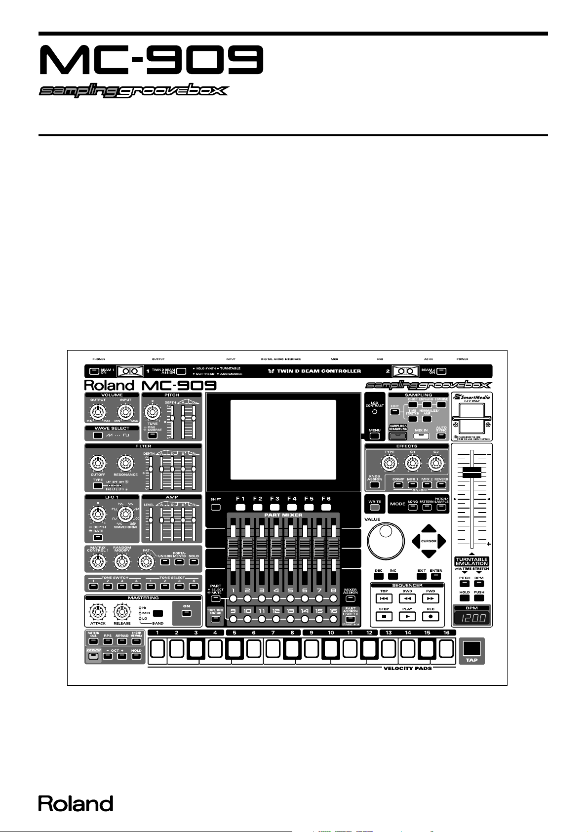
MC-909: Sampling groovebox
Sound Generator Section
Maximum Polyphony 64 voices
Sampling Rate 44.1 kHz
Parts 16 (Main) + 16 (RPS)
Waves 693
Patches
Preset 800
User 256
Card 256
Rhythm Set
Preset 72
User 128
Card 128
Sampling Section
Audio Format 16-bit linear
(File Type: WAV/AIFF)
Maximum Polyphony 64 voices
Sampling Rate 44.1 kHz (fixed)
Sampling Time
• Internal memory (16 MB) only
mono: 180 sec. approx. (stereo: 90 sec. approx.)
• with DIMM (256 MB)
mono: 51 min. approx. (stereo: 25.5 min. approx.)
Samples
User 2,000
Card 7,000 (128 MB SmartMedia)
Sequencer Section
Parts 16 + Tempo/Mute Control
Resolution 480 ticks per quarter note
Tempo 5-300
Maximum Note Storage approx. 1,300,000 notes
Patterns
Preset 215
RPS 440
User 200
Card 999
Recording Mode Realtime, TR-REC, Step
Songs 50
Arpeggio Style
Preset 128
User 128
Chord Memory
Preset 64
User 128
RPS Set 50
Pattern Set 50
Effects Section
Reverb 1 (4 types)
Compressor 1 (1 type)
Multi-effects (MFX) 2
(MFX1: 38 types)
(MFX2: 47 types)
Pitch Shifter
(for external input)1 (1 type)
Mastering Section
3-bands Compressor1 (1 type)
Expansion Slot
Wave Expansion Board SRX Series: 1 slot
DIMM: 1 slot
Number of pins: 168-pin
Speed: 100 MHz (PC100 CL=2)
133 MHz (PC133 CL=3)
Voltage: 3.3 V
Capacity: 128 MB
256 MB
Board height: 38 mm or less
External Memory
SmartMedia card: 1 slot
8MB/16MB/32MB/64MB/128MB (3.3V)
Controllers, Display
Display
QVGA LCD
BPM Display: 7 segment 4 character (LED)
Control Knob
Pitch: 1 (FINE TUNE/COARSE TUNE)
Filter: 2 (CUTOFF, RESONANCE)
LFO 1: 2 (DEPTH/RATE, WAVEFORM)
Sound Others: 3 (FAT, RANDOM MODIFY, MATRIX CONTROL 1)
Effects: 3 (TYPE, C1, C2)
Mastering: 2 (ATTACK, RELEASE)
OUTPUT Volume: 1
INPUT Volume: 1
Control Slider
Envelope: 13 (Pitch/Filter/Amp)
Part Mixer: 8
Turntable Emulation (100 mm): 1
Other Controllers
Twin D Beam Controller
Velocity Pads
Connectors
MIX OUTPUT Jacks (L (MONO), R)
DIRECT 1 OUTPUT Jacks (L (MONO), R)
DIRECT 2 OUTPUT Jacks (L (MONO), R)
IPUT Jacks (L (MONO), R)
Headphones Jack
MIDI Connectors (IN, OUT)
USB Connector
Digital Audio Interface
IN/OUT (OPTICAL, COAXIAL)
AC Inlet
Power Supply
AC 117 V, AC 230 V, AC 240 V
Power Consumption
20 W
Dimensions
491 (W) x 386 (D) x 123 (H) mm
19-3/8 (W) x 15-1/4 (D) x 4-7/8 (H) inches
Weight
6.0 kg
13 lbs 4 oz
Accessories
Owner’s Manual English(#72128501)
Japanese(#72128389)
Sample Data (Audio) CD(#********)
2
Page 3

Power Cord 120V (#02129289)
230V(#02894345)
230VE(#02894234)
240VA(#02129301)
Card Protecter(#01346312)
Options
Wave Expansion Board: SRX Series
MIDI IMPLEMENTATION English(#17041253)
Japanese(#17041252)
* In the interest of product improvement, the specifications and/or appearance of
this unit are subject to change without prior notice.
MC-909
3
Page 4
Nov.2002
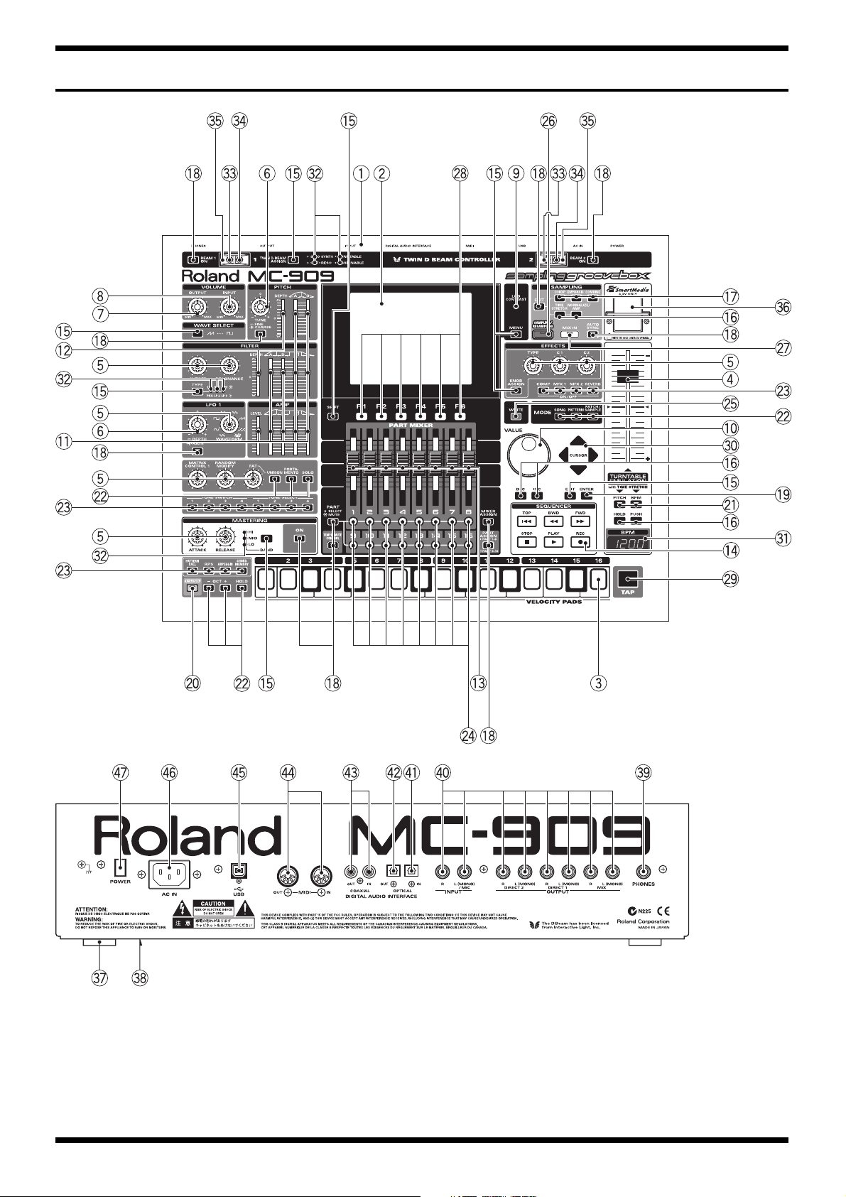
LOCATION OF CONTROLS
fig.Top
fig.Rear
4
Page 5

LOCATION OF CONTROLS PARTS LIST
No PART CODE Part name Description Q'TY
1 03017789 TOP PANEL 1
2 03017756 DISPLAY COVER 1
01124234 LM320191 LCD UNIT 1
3 03017690 RUBBER SW A 2
03017701 RUBBER SW ESCT 2
03231801 SML-311UT LED (RED) 17
4 01904101 J S-KNOB L BLK/LCG 1
01903778 100M/M SLIDE POT. RSA0N1144 1
5 02452912 J R-KNOB SF-A BLK/LCG 15
03231745 11M/M ROTARY POT. RK11K1140A23 11
6 02452912 J R-KNOB SF-A BLK/LCG 15
03231734 11M/M ROTARY POT. RK11K114001Z 2
7 02452912 J R-KNOB SF-A BLK/LCG 15
03232456 14M/M ROTARY POT. RK14K12D0DON 1
8 02452912 J R-KNOB SF-A BLK/LCG 15
03231756 14M/M ROTARY POT. RK14K12D0D0Q 1
9 03231723 9M/M ROTARY POT. RK09K1130A5R 1
10 22485303 D R-KNOB(ALPHA-DIAL) L BLK 248-303 1
40235189 RING SE-9 1
03122134 EC12E2420802 1
11 01346112 KNOB MOLD KNOB BLK 13
03231767 30M/M SLIDE POTENTIOMET RS30111A602N 11
12 01346112 KNOB MOLD KNOB BLK 13
03231778 30M/M SLIDE POTENTIOMET RS30111C600G 2
13 01902289 U S-KNOB M BLK LCG 8
03232056 45M/M SLIDE POTENTIOMET RS45111A900F 8
14 03014223 RUBBER SW B 1
03017712 SPACER 1
03231801 SML-311UT LED (RED) 17
01784978 SML-020MLT LED (RED/GREEN) 1
15 00900189 D S-KEYTOP SX1H BLK 17
01343478 SKQNAE TACT SWITCH 87
16 00900190 D S-KEYTOP SX2H BLK
01343478 SKQNAE TACT SWITCH 87
17 00904245 D S-KEYTOP SX3H BLK
01343478 SKQNAE TACT SWITCH 87
18 00900145 D S-KEYTOP SD1H BLK
01343478 SKQNAE TACT SWITCH 87
00348490 SLR-325VCT31 LED (RED) 42
19 00900145 D S-KEYTOP SD1H BLK
01343478 SKQNAE TACT SWITCH 87
03122112 SLR-343BBT3F LED (BLUE) 2
20 01016867 D S-KEYTOP SD1H LCG 1
01343478 SKQNAE TACT SWITCH 87
03122112 SLR-343BBT3F LED (BLUE) 2
21 00900156 D S-KEYTOP SD2H BLK 7
01343478 SKQNAE TACT SWITCH 87
00348490 SLR-325VCT31 LED (RED) 42
22 00900167 D S-KEYTOP SD3H BLK 3
01343478 SKQNAE TACT SWITCH 87
00348490 SLR-325VCT31 LED (RED) 42
23 00900178 D S-KEYTOP SD4H BLK 4
01343478 SKQNAE TACT SWITCH 87
00348490 SLR-325VCT31 LED (RED) 42
24 02450201 Y C-KEYTOP MX4H CLR 4
01343478 SKQNAE TACT SWITCH 87
01787045 SLR-325DCT31 LED (ORANGE) 16
25 01129767 D S-KEYTOP SX1H DRD 1
01343478 SKQNAE TACT SWITCH 87
26 22495344 DS-KEYTOP MD1H RED BRWN(W/WINDOW) 1
01343478 SKQNAE TACT SWITCH 87
00348490 SLR-325VCT31 LED (RED) 42
27 00125734 D S-KEYTOP MD1H LCG 1
01343478 SKQNAE TACT SWITCH 87
00348490 SLR-325VCT31 LED (RED) 42
28 01013301 DS-KEYTOP SX1H LCG 6
01343478 SKQNAE TACT SWITCH 87
29 02016390 Y S-KEYTOP LX1H BLK 1
03231790 SKPDAED010 TACT SWITCH 1
30 01234090 D T-KEYTOP MX4B BLK 1
01343478 SKQNAE TACT SWITCH 87
31 03017767 LED COVER 1
01903512 LNM223KS01C 7SEG LED 2
32 00899023 LNJ282RKRXE LED (RED) 10
01343090 LED SPACER 4
33 03126134 TLN233 LED 2
34 01900612 TPS611 DIODE 2
MC-909
5
Page 6

Nov.2002
No PART CODE Part name Description Q'TY
35 01343089 ESCUTCHEON D-BEAM CONTROLLER ESCT BLK 2
36 01343101 D C-ESCT D C-ESCT BX1H BLK 1
01780712 CN015P-3013-0 CARD CONECTR 1
37 12359139 RUBBER FOOT FF-018 BLK 4
38 03017790 BOTTOM COVER 1
39 13449284 HLJ7001-01-3010 6.5MM JACK 1
40 13449283 HLJ7101-01-3010 6.5MM JACK 8
41 02565401 GP1FA501RZ OPTICAL CONNECTOR RX 1
42 02565390 GP1FA501TZ OPTICAL CONNECTOR TX 1
43 03231812 YKC21-4173 PIN JACK (ORG)PIN X 2 1
44 13429825 YKF51-5054 2PZ MIDI CONNECTOR 1
45 02781101 YKF45-0020 USB CONNECTOR 1
46 02129389 M1818A(PWI1818) 2P AC INLET 1
47 12499175 G S-BUTTON S1H BLK 249-175 1
01676512 SDKLA1-B PUSH SWITCH 1
6
Page 7

MC-909
7
Page 8
Nov.2002
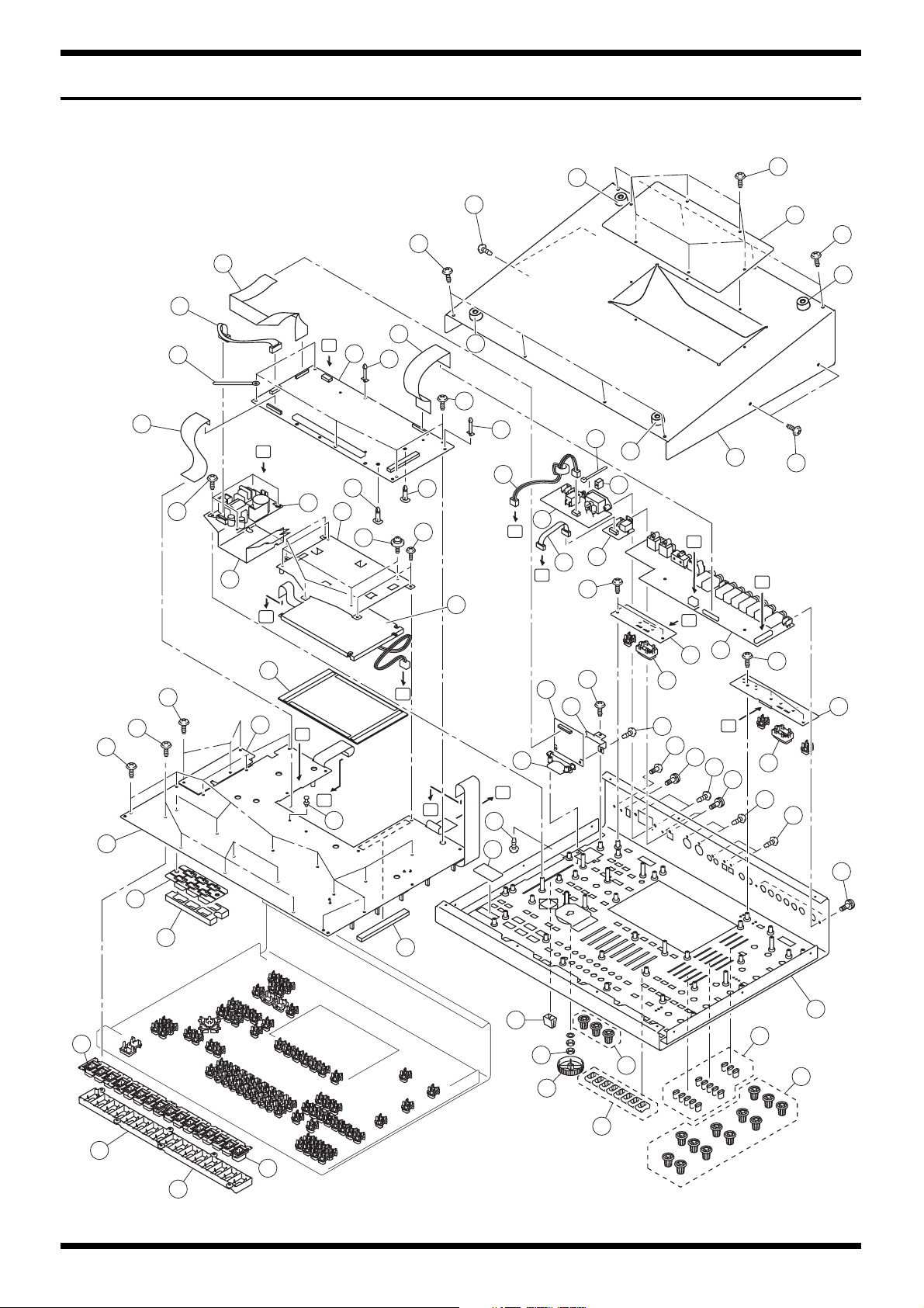
EXPLODED VIEW
fig.explo
29
31
27
3
a
a
28
23
30
11
21
22
e
b
G
F
b
18
8
5
E
3
b
21
25
12
F
G
7
26
39
3
38
12
b
D
C
a
4
a
3
2
a
B
16
12
13
9
b
c
b
14
15
12
E
C
4
2
D
19
20
A
B
g
10
33
h
1
34
b
2
6
35
12
32
g
d
A
e
f
b
12
2
3
e
g
g
e
1
7
3
35
8
36
17
16
17
Page 9

EXPLODED VIEW PARTS LIST
[PARTS]
No PART CODE Part name Description Q’TY
1 03017789 TOP PANEL 1
2 03017790 BOTTOM COVER 1
3 12359139 RUBBER FOOT FF-018 BLK 4
4 03017778 EXP COVER 1
5 03017890 DISPLAY HOLDER 1
6 03017745 D C-ESCT HOLDER 1
7 01124234 LM320191 LCD UNIT 1
8 01785823 A1DU2L3B034 SWITCHING REGULATOR 1
9 03017756 DISPLAY COVER 1
10 03017767 LED COVER 1
11 72128412 MAIN BOARD ASSY 1
12 72128401 PANEL BOARD ASSY 1
13 72128390 JACK BOARD ASSY 1
14 03014223 RUBBER SW B 1
15 03017712 SPACER 1
16 03017690 RUBBER SW A 2
17 03017701 RUBBER SW ESCT 2
18 02894367 INSULATING COVER DA-2496 SW-PS 1
19 03230101 ISOLATOR 1
20 01343101 D C-ESCT D C-ESCT BX1H BLK 1
21 02238145 PWB SPACER WLS-20-0 2
22 02019034 PWB SPACER RSPLS-12L 1
23 01902756 PWB SPACER RSPS-12L 1
24 03017867 CARD SPACER MPS-10-0 1
25 03120801 WIRING W3 1
26 03017956 WIRING W1 1
27 02679390 WIRING 7X150-P2.5-XHP-XHP-F 1
28 03017945 BAN CARD BNCD-P=1.00-K-24-260 1
29 02343945 BAN CARD BNCD-P=1.00-K-28-100 1
30 03017934 BAN CARD BNCD-P=1.00-K-30-100 1
31 40017356 COATING CLIP CS-4 1
32 01343089 ESCUTCHEON D-BEAM CONTROLLER ESCT BLK 2
33 01904101 J S-KNOB L BLK/LCG 1
34 22485303 D R-KNOB(ALPHA-DIAL) L BLK 248-303 1
35 02452912 J R-KNOB SF-A BLK/LCG 15
36 01902289 U S-KNOB M BLK LCG 8
37 01346112 KNOB MOLD KNOB BLK 13
38 12499175 G S-BUTTON S1H BLK 249-175 1
39 40016512 INSULOK TIE 80M/M T-18S 1
MC-909
[SCREW]
No PART CODE Part name Description Q’TY
a 40011090 SCREW 3X6 BINDING TAPTITE B BZC 18
b 40011056 SCREW 3X6 BINDING TAPTITE B ZC 39
c 40011101 SCREW 3X8 BINDING TAPTITE B BZC 6
d 40230590 SCREW M3X10 BINDING MACHINE NI 1
e 40011490 SCREW M3X6 PAN MACHINE W/SW BZC 9
f 40238501 SCREW 4X8 BINDING TAPTITE P BZC 2
g 40011312 SCREW 3X8 BINDING TAPTITE P BZC 10
h 40235189 RING SE-9 1
9
Page 10
Nov.2002
PARTS LIST
fig.part1e
SAFETY PRECAUTIONS:
The parts marked have
safety-related characteristics. Use
only listed parts for replacement.
NOTE: The parts marked # are new. (initial parts)
CASING
# 03017756 DISPLAY COVER 1
# 03017767 LED COVER 1
# 03017778 EXP COVER 1
# 03017701 RUBBER SW ESCT 2
# 03017789 TOP PANEL 1
# 03017790 BOTTOM COVER 1
CHASSIS
# 03017745 D C-ESCT HOLDER 1
# 03017890 DISPLAY HOLDER 1
KNOB, BUTTON
# 03017690 RUBBER SW A 2
# 03014223 RUBBER SW B 1
01343089 ESCUTCHEON
01343101 D C-ESCT D C-ESCT BX1H BLK 1
00900167 D S-KEYTOP SD3H BLK 3
00900156 D S-KEYTOP SD2H BLK 7
02450201 Y C-KEYTOP MX4H CLR 4
02016390 Y S-KEYTOP LX1H BLK 1
01234090 D T-KEYTOP MX4B BLK 1
01129767 D S-KEYTOP SX1H DRD 1
01016867 DS KEYTOP SD1H LCG 1
01013301 DS-KEYTOP SX1H LCG 6
00900189 D S-KEYTOP SX1H BLK 17
00900178 D S-KEYTOP SD4H BLK 4
00125734 D S-KEYTOP MD1H LCG 1
00900190 D S-KEYTOP SX2H BLK
00904245 D S-KEYTOP SX3H BLK
00900145 D S-KEYTOP SX1H BLK
12499175 G S-BUTTON S1H BLK 249-175 1
22495344 DS-KEYTOP
01346112 KNOB MOLD KNOB BLK 13
02452912 J R-KNOB SF-A BLK/LCG 15
22485303 D R-KNOB(ALPHA-DIAL) L BLK 248-303 1
01904101 J S-KNOB L BLK/LCG 1
01902289 U S-KNOB M BLK LCG 8
CONSIDERATION ON PARTS ORDRING
When ordering any parts listed in the parts list, please specify the following items in the order sheet.
Failure to completely fill the above items with correct number and description will result in delayed or even
undelivered replacement.
QTY PART NUMBER DESCRIPTION MODEL NUMBER
Ex. 10 22575241 Sharp Key C-20/50
15 2247017300 Knob (orange) DAC-15D
D-BEAM CONTROLLER ESCT BLK
MD1H RED BRWN(W/WINDOW)
2
1
SWITCH
JACK, EXT TERMINAL
10
01676512 SDKLA1-B PUSH SWITCH SW85 on PANEL SHEET 1
03231790 SKPDAED010 TACT SWITCH SW84 on PANEL SHEET 1
01343478 SKQNAE TACT SWITCH SW37,SW36,SW35,SW34,SW33,SW31,SW38
,SW46,SW32,SW39,SW40,SW41,SW42,SW4
3,SW30,SW45,SW22,SW47,SW44,SW19,SW
11,SW12,SW13,SW14,SW15,SW16,SW24,S
W18,SW29,SW20,SW21,SW57,SW23,SW48,
SW25,SW26,SW27,SW28,SW17,SW79,SW55
,SW72,SW73,SW74,SW75,SW76,SW70
,SW78,SW69,SW80,SW81,SW82,SW83,SW8
6,SW87,SW88,SW90,SW77,SW58,SW50,SW
51,SW52,SW53,SW54,SW10,SW71,SW89,S
W49,SW59,SW60,SW61,SW62,SW63,SW64,
SW65,SW66,SW67,SW56,SW4,SW1,SW3,S
W8,SW7,SW6,SW5,SW91,SW9 on PANEL
SHEET
13449283 HLJ7101-01-3010 6.5MM JACK JK8,JK3,JK5,JK9,JK4,JK2,JK1,JK7 on JACK
BOARD
13449284 HLJ7001-01-3010 6.5MM JACK JK6 on JACK BOARD 1
02129389 M1818A(PWI1818) 2P AC INLET JK1 on PANEL SHEET 1
87
8
Page 11

MC-909
JACK, EXT TERMINAL
02781101 YKF45-0020 USB CONNECTOR JK1 on MAIN BOARD,JK2 on PANEL
SHEET
01780712 CN015P-3013-0 CARD CONECTR CN7 on PANEL SHEET 1
03231812 YKC21-4173 PIN JACK (ORG)PIN X 2 JK10 on JACK BOARD 1
13429825 YKF51-5054 2PZ MIDI CONNECTOR JK11 on JACK BOARD 1
DISPLAY UNIT
01124234 LM320191 LCD UNIT 1
NOTE: Replacement LM320191 should be made on a unit base.
01903512 LNM223KS01C 7SEG LED LED97,LED96 on PANEL SHEET 2
NOTE: Replacement LNM223KS01C should be made on a unit base.
POWER SUPPLY UNIT
01785823 A1DU2L3B034 SWITCHING REGULATOR 1
NOTE: Replacement A1DU2L3B034 should be made on a unit base.
PCB ASSY
# 72128390 JACK BOARD ASSY 1
# 72128401 PANEL BOARD ASSY 1
NOTE: ‘PANEL BOARD ASSY’ includes the following parts.
01343090 LED SPACER 4
# 72128412 MAIN BOARD ASSY 1
1
IC
# 03014812 HD6433061G43FP IC (16BIT CPU) IC2 on PANEL SHEET 1
00129278 SSC1080F0B IC IC20 on PANEL SHEET 1
01455956 TC223C660CF-503 IC (RA08-503) IC27 on MAIN BOARD 1
02231767 RA0A-101 (TC223C080AF-101) IC (DSP) IC22 on MAIN BOARD 1
# 02782778 TC200E06 (PPC) IC (I/F) IC4 on MAIN BOARD 1
# 02900456 TC200E1005AF-11 (BA) IC (I/F) IC21 on MAIN BOARD 1
# 03017601 TC58256AFT IC (FLASH MEMORY) IC53 on MAIN BOARD 1
# 03017590 UDA1351TS IC (DIR DAC) IC75 on MAIN BOARD 1
02454878 M62220FP-600C IC (REGULATOR) DC-DC IC IC55 on MAIN BOARD 1
02451912 HD74LV00ATELL IC (CMOS) IC74 on MAIN BOARD 1
02451723 HD74LV138ATELL IC (CMOS) IC6,IC8 on PANEL SHEET 2
01567190 TC74VHCU04F(EL) IC (CMOS) IC6 on JACK BOARD 1
15269219H0 HD74LS05FPEL IC (TTL) IC7 on JACK BOARD 1
01783523 TC74VHCT245AFT(EL) IC (CMOS) IC3 on PANEL SHEET 1
00458312 NJM2360M IC (REGULATOR) IC4 on PANEL SHEET 1
02451690 HD74LV08ATELL IC (CMOS) IC12 on MAIN BOARD 1
00344390 TA7805F(TE16L) IC (REGULATOR) IC58 on MAIN BOARD 1
15229706 TLP552 PHOTO COUPLER IC9 on JACK BOARD 1
15289105 UPC4570G2-E2 IC (BIPOLAR OP AMP) IC22,IC23,IC24,IC28,IC25 on PANEL
SHEET
15289128 BA10324AF IC (OP AMP) IC12 on PANEL SHEET 1
15189261 M5218AFP-600E IC (BIPOLAR OP AMP) IC3,IC4,IC5,IC8,IC1,IC2 on JACK
BOARD,IC61,IC64,IC68,IC70,IC71,IC59 on
MAIN BOARD
01121834 TC7W74FU TE12L IC IC21 on PANEL SHEET 1
02892334 TC74LCX245FT(EL) IC (CMOS) IC3,IC5 on MAIN BOARD 2
# 02900690 P2027A-08TR IC IC89 on MAIN BOARD 1
01677689 HD74HC238FPEL IC (CMOS) IC27,IC26 on PANEL SHEET 2
02675645 HD74LV04ATELL IC (CMOS) IC10,IC17 on MAIN BOARD 2
01348912 TC7SH08FU(TE85L) IC (CMOS) IC84,IC45 on MAIN BOARD 2
01348956 TC7SH00FU(TE85L) IC (CMOS) IC82 on MAIN BOARD 1
15199937 M51953BFP-600C IC (RESET) IC18 on MAIN BOARD 1
02565390 GP1FA501TZ TX IC (OPTICAL CONNECTOR) CN3 on JACK BOARD 1
02675656 HD74LV11ATELL IC (CMOS) IC11,IC13,IC31 on MAIN BOARD 3
02675689 HD74LV245ATELL IC (CMOS) IC7,IC40,IC30,IC51,IC8,IC39,IC32,IC35,IC3
4,IC44,IC23,IC29 on MAIN BOARD
02673812 HY57V641620HGT-P IC (DRAM) IC6,IC20,IC24,IC2 on MAIN BOARD 4
02568489 GM71V18163CT-6 IC (DRAM) IC25 on MAIN BOARD 1
02675678 HD74LV139ATELL IC (CMOS) IC79,IC38,IC15 on MAIN BOARD 3
02565401 GP1FA501RZ RX IC (OPTICAL CONNECTOR) CN2 on JACK BOARD 1
01348945 TC7SH32FU(TE85L) IC (CMOS) IC81,IC41 on MAIN BOARD 2
01349590 TC7WU04FU(TE12L) IC (CMOS) IC26,IC16 on MAIN BOARD 2
01890367 TC74VHC175FT(EL) IC (COMS) IC52,IC48 on MAIN BOARD 2
01785178 TC9271FS IC (DIGITAL OUT IF) IC62 on MAIN BOARD 1
15259884 TC7S08F(TE85L) IC (CMOS) IC5 on PANEL SHEET 1
02671378 LC324260BJ-60-TLM IC (DRAM) IC37 on MAIN BOARD 1
02568478 M66273FP LCD-DRIVER IC49 on MAIN BOARD 1
******** MBM29LV160BE70 IC (FLASH MEMORY) IC19 on MAIN BOARD 1
5
6
12
11
Page 12

Nov.2002
IC
TRANSISTOR
DIODE
02900978 M66291GP IC (USB CONTROLLER) IC36 on MAIN BOARD 1
15319105 2SC3326-A TRANSISTOR Q11,Q10,Q9,Q8,Q7,Q6,Q5,Q4 on JACK
BOARD
02670989 DTB113ZK-146T TRANSISTOR Q29 on PANEL SHEET 1
15139123 2SK184-GR(TPE4) TRANSISTOR Q3 on JACK BOARD 1
02671023 2SC3052-T12-1E TRANSISTOR Q13,Q14 on JACK BOARD 2
15309104 2SA1586-GR(TE85R) TRANSISTOR Q11,Q12 on MAIN BOARD 2
02671256 RT1P141C-T12-1 TRANSISTOR Q16 on JACK BOARD 1
15309101 2SA1037AKT146R TRANSISTOR Q1,Q12 on JACK BOARD 2
02671267 RT1N141C-T12-1 TRANSISTOR Q13,Q14 on MAIN BOARD,Q2,Q30,Q1 on
PANEL SHEET
00562012 2SC3265-Y(TE85R) TRANSISTOR Q28,Q32 on PANEL SHEET 2
15319101 2SC2412KR T146 TRANSISTOR Q55,Q3,Q4,Q51,Q52,Q54,Q56,Q57,Q58,Q53
on PANEL SHEET
15329103T0 2SK880-GR(TE85R) FET Q7,Q9,Q10,Q8 on MAIN BOARD 4
02017512 PW MOSFET 2SJ325-Z-E1 TRANSISTOR Q6 on MAIN BOARD 1
00899023 LNJ282RKRXE LED LED102,LED90,LED88,LED41,LED33,LED3
1,LED25,LED17,LED9,LED89 on PANEL
SHEET
01787045 SLR-325DCT31 LED (ORANGE) LED76,LED35,LED27,LED43,LED49,LED50
,LED54,LED55,LED58,LED59,LED62,LED4
4,LED63,LED67,LED72,LED68 on PANEL
SHEET
01784978 SML-020MLT LED LED94 on PANEL SHEET 1
00348490 SLR-325VCT31 LED (RED) LED87,LED51,LED64,LED73,LED77,LED80
,LED81,LED84,LED86,LED93,LED95,LED1
00,LED101,LED56,LED47,LED85,LED12,LE
D69,LED46,
LED3,LED4,LED5,LED8,LED11,LED6,LED
13,LED14,LED16,LED19,LED20,LED45,LE
D21,LED40,LED38,LED36,LED37,LED32,L
ED30,LED29,LED28,LED24,LED22 on
PANEL SHEET
01900612 TPS611 DIODE Q35,Q34 on PANEL SHEET 2
01897189 MA147-(TX) ARRAY DIODE DA5,DA2,DA4,DA3 on MAIN
BOARD,DA84,DA95,DA88,DA87,DA83,D
A60,DA64 on PANEL SHEET
00129767 RD10M-T1B B2 ZENER DIODE D2 on JACK BOARD 1
01017512 RB411D T146 SCHOTTKY DIODE D1 on PANEL SHEET 1
15339412 U1BC44(TE12L) DIODE D1 on JACK BOARD 1
15339130 MA142WK-(TX) ARRAY DIODE DA9,DA6,DA8,DA7 on MAIN
BOARD,DA90,DA71,DA48,DA85,DA51,D
A52,DA55,DA56,DA65,DA66,DA67,DA68,
DA1,DA70,DA45,DA72,DA73,DA74,DA75,
DA76,DA77,DA78,DA79,DA80,DA81,DA8
2,DA86,DA92,DA69,DA19,DA2,DA3,DA4,
DA6,DA7,DA9,DA10,DA12,DA13,DA15,D
A49,DA18,DA44,
DA34,DA42,DA41,DA38,DA16,DA35,DA2
2,DA32,DA31,DA29,DA28,DA26,DA25,DA
23,DA37 on PANEL SHEET
15339105 DAN202K T146 (CHIP) ARRAY DIODE DA3,DA1,DA2 on JACK BOARD 3
01897178 MA142WA-(TX) ARRAY DIODE DA27,DA39,DA93,DA53,DA47,DA40,DA9
4,DA21,DA24,DA20,DA17,DA14,DA11,DA
8,DA5,DA46 on PANEL SHEET
03231801 SML-311UT LED (RED) LED2,10,18,26,34,42,48,53,57,61,66,70,74,78,
71,75,79 on PANEL SHEET
03122112 SLR-343BBT3F LED 2
03126134 TLN233 LED 2
8
3
10
10
16
42
7
4
16
17
RESISTOR
12
00567212 RPC05T 332 J MTL.FILM RESISTOR R104,R66,R103,R102,R101,R100,R99,R98,R6
0,R36,R20,R4,R105,R48 on JACK
BOARD,R197,R184,R190,R225,R232,R205
on MAIN BOARD,R31 on PANEL SHEET
00567289 RPC05T 103 J MTL.FILM RESISTOR R59,R1,R15,R45,R65,R73,R35 on JACK
BOARD,R107,R84,R92,R93,R94,R95,R105,R
82,R109,R110,R111,R112,R114,R118,R119,R
103,R27,R33,R134,R13,R17,R22,R90,R24,R80
,R35,R36,R39,R40,R42,R43,R44,R23,R264,R2
5,R313,R266,R139,R248
,R247,R244,R243,R242,R164,R238,R195,R18
8,R176,R175,R174,R166,R165,R311,R241 on
MAIN BOARD,R40,R1,R3,R7,R28 on PAN-
EL SHEET
00567323 RPC05T 223 J MTL.FILM RESISTOR R22,R21,R33,R34 on JACK BOARD 4
1
5
Page 13

MC-909
RESISTOR
00567067 RPC05T 221 J MTL.FILM RESISTOR R31,R79,R82,R83,R18 on JACK
BOARD,R198,R191,R185,R206,R226,R233
on MAIN BOARD,R258,R257 on PANEL
SHEET
00567234 RPC05T 392 J MTL.FILM RESISTOR R252,R256,R245,R243 on PANEL SHEET 4
00567245 RPC05T 472 J MTL.FILM RESISTOR R97,R85,R74 on JACK
BOARD,R161,R194,R193,R163,R159,R53,R1
71 on MAIN BOARD,R222 on PANEL
SHEET
00567201 RPC05T 272 J MTL.FILM RESISTOR R107,R106,R28,R12 on JACK BOARD 4
00567256 RPC05T 562 J MTL.FILM RESISTOR R43,R55 on JACK
BOARD,R200,R196,R189,R218,R180,R228
on MAIN BOARD
00567045 RPC05T 151 J MTL.FILM RESISTOR R269,R270 on PANEL SHEET 2
00567001 RPC05T 750 J MTL.FILM RESISTOR R81,R80 on JACK BOARD 2
00566867 RPC05T 100 J MTL.FILM RESISTOR R260,R261,R262,R263 on MAIN BOARD 4
00566912 RPC05T 220 J MTL.FILM RESISTOR R102,R339,R324,R281,R270,R104,R340,R100
,R45,R34,R130 on MAIN BOARD
00567112 RPC05T 471 J MTL.FILM RESISTOR R169,R167,R177,R179 on MAIN
BOARD,R24,R20,R13,R14,R15,R21,R22,R23
on PANEL SHEET
00566934 RPC05T 330 J MTL.FILM RESISTOR R7,R8,R10,R72,R302,R62,R63,R297,R76,R71,
R70,R74,R75,R298,R332,R336,R335,R300,R3
33,R314,R329,R328,R1,R2,R3,R4,R6,R326,R3
25,R323,R334 on MAIN BOARD
00567078 RPC05T 271 J MTL.FILM RESISTOR R134 on PANEL SHEET 1
00566989 RPC05T 560 J MTL.FILM RESISTOR R68,R272,R62,R66,R70,R72,R74,R240,R261,
R263,R264,R266,R271,R267,R262 on PANEL
SHEET
00567312 RPC05T 183 J MTL.FILM RESISTOR R235,R106 on MAIN BOARD,R39 on PAN-
EL SHEET
00346134 MCR25 JZH J 1R0 MTL.FILM RESISTOR R33 on PANEL SHEET 1
00567367 RPC05T 393 J MTL.FILM RESISTOR R41 on PANEL SHEET 1
00567190 RPC05T 222 J MTL.FILM RESISTOR R133 on MAIN BOARD,R253,R244 on PAN-
EL SHEET
00566967 RPC05T 470 J MTL.FILM RESISTOR R287,R79,R81,R131,R282,R283,R284,R294,R
337,R286,R338,R327,R293,R292,R291,R290,
R289,R288,R285 on MAIN
BOARD,R276,R60,R273,R275,R64,R260,R27
4 on PANEL SHEET
00567478 RPC05T 334 J MTL.FILM RESISTOR R216,R173 on MAIN BOARD 2
00567034 RPC05T 121 J MTL.FILM RESISTOR R89 on JACK BOARD
,R191,R48,R50,R52,R56,R215,R217,R54 on
PANEL SHEET
00567456 RPC05T 224 J MTL.FILM RESISTOR R194,R205 on PANEL SHEET 2
00567445 RPC05T 184 J MTL.FILM RESISTOR R212,R170 on MAIN BOARD 2
00567412 RPC05T 104 J MTL.FILM RESISTOR R87,R70,R51,R93,R52,R58,R57,R69,R63,R64,
R47,R46,R40,R39,R27,R10 on JACK
BOARD,R199,R168,R172,R186,R192,R211,R
222,R227,R236,R208 on MAIN
BOARD,R251,R93,R96,R248,R111,R114,R12
3,R128,R131,R136,R137 on PANEL SHEET
00567389 RPC05T 563 J MTL.FILM RESISTOR R14 on JACK BOARD,R255,R256 on MAIN
BOARD,R201,R212 on PANEL SHEET
00567378 RPC05T 473 J MTL.FILM RESISTOR R3,R13,R71,R75,R78,R2 on JACK
BOARD,R231,R234,R229 on MAIN BOARD
00566990 RPC05T 680 J MTL.FILM RESISTOR R277 on MAIN BOARD 1
02679290 RA4C1632-103-J RESISTOR-ARRAY RA68,RA88,RA71,RA66,RA65,RA49,RA25,
RA48,RA30,RA26,RA72 on MAIN BOARD
01906667 MNR14 EOAB J 100 RESISTOR-ARRY RA13,RA6,RA14,RA4 on PANEL SHEET 4
01906678 MNR14 EOAB J 103 RESISTOR-ARRY RA1,RA12,RA2 on PANEL SHEET 3
02456878 EXB2HV220JV RESISTOR-ARRAY RA73,RA67,RA64,RA62,RA56,RA77,RA84,
RA85,RA86,RA9,RA40,RA37,RA36,RA34,R
A60,RA20,RA3,RA8,RA27,RA50,RA52,RA5
4,RA43,RA57,RA31,RA33 on MAIN
BOARD
15419702 RR1220P-102-D 1K OHM 1/10W MTL.FILM RESISTOR R155 on MAIN BOARD 1
15229941 10KD-5 THERMISTOR RESISTOR R30 on PANEL SHEET 1
01455856 RR1220Q-680-D MTL.FILM RESISTOR R152 on MAIN BOARD 1
02780323 RA4C1632-220-J RESISTOR-ARRAY RA58,RA53 on MAIN BOARD 2
02780312 RA4C1632-0R0-J RESISTOR-ARRAY RA91 on MAIN BOARD 1
00567178 RPC05T 152 J MTL.FILM RESISTOR R86 on JACK BOARD,R148 on MAIN
BOARD,R34 on PANEL SHEET
02679323 RA4C1632-330-J RESISTOR-ARRAY RA45,RA6,RA2 on MAIN BOARD 3
01906656 MNR14 EOAB J 000 RESISTOR-ARRAY RA11,RA10,RA3 on PANEL SHEET 3
00567023 RPC05T 101 J MTL.FILM RESISTOR R50,R91,R68,R62,R16,R24,R6,R38,R77,R90,
R29 on JACK
BOARD,R183,R182,R181,R245,R246,R129,R
278,R280,R315,R316,R274,R128,R127,R126,
R124,R123,R122,R121,R58,R57,R54,R51,R32,
R319,R125,R318,R320,R321,R322,R330,R331
,R317 on MAIN BOARD,
2
1
6
11
8
31
15
1
2
7
8
11
2
3
11
26
1
49
13
Page 14

Nov.2002
RESISTOR
02678534 EXB2HV103V RESISTOR-ARRAY RA69 on MAIN BOARD 1
# 02904445 EXB2HV330JV REISTER-ARRAY RA4,RA10,RA21,RA28 on MAIN BOARD 4
00567467 RPC05T 274 J MTL.FILM RESISTOR R230 on MAIN BOARD 1
00567556 RPC05T 105 J MTL.FILM RESISTOR R7 on JACK BOARD,R156,R99,R50 on
00567345 RPC05T 333 J MTL.FILM RESISTOR R41,R53 on JACK BOARD 2
00566923 RPC05T 270 J MTL.FILM RESISTOR R145,R146 on MAIN BOARD 2
01013890
01011856 RPC05T 0R0 J MTL.FILM RESIST0R R310,R312,R157,R140,R30,R41,R68,R73,R83,
00567501 RPC05T 474 J MTL.FILM RESISTOR R36,R42,R37 on PANEL SHEET 3
00567056 RPC05T 181 J MTL.FILM RESISTOR R210,R38,R199,R218,R219 on PANEL
00567123 RPC05T 561 J MTL.FILM RESISTOR R202,R213 on PANEL SHEET 2
00567134 RPC05T 681 J MTL.FILM RESISTOR R23,R37,R67,R5,R61,R49 on JACK
00567156 RPC05T 102 J MTL.FILM RESISTOR R92,R54,R42,R30,R17,R76,R84,R72 on JACK
15399952 MCR50JZH470 1/2W CHIP RESISTOR R56,R44 on JACK BOARD 2
RR1220P-221-D 220 OHM 1/10W
MTL.FILM RESISTOR R153,R154 on MAIN BOARD 2
R250,R247,R209,R207,R198,R196,R132,R129
,R126,R125,R124,R120,R119,R118,R127,R98,
R87,R89,R86,R90,R91,R76,R94,R105,R75,R4
6,R104,R103,R102,R101,R100,R117,R82,R11
6,R115,R112,R109,R85,R88,R83,R81,R80,R79
,R108,R107,R78,R77,R106,R84 on PANEL
SHEET
MAIN BOARD
R87,R96,R97,R98,R116,R214,R136,R309,R14
1,R144,R147,R150,R187,R237,R239,R258,R3
04,R305,R306,R307,R308,R120 on MAIN
BOARD,R221,R220,R189,R188,R187,R140,R
45,R2,R5,R10,R12,R25,R138,R32 on PANEL
SHEET
SHEET
BOARD,R158,R101,R55 on MAIN BOARD
BOARD,R143,R91 on MAIN
BOARD,R29,R211,R208,R200,R197,R164,R1
62,R44,R43,R6,R11 on PANEL SHEET
3
14
5
3
11
POTENTIOMETER
CAPACITOR
01903778
03231745
03231734
03232456
03231756
03231723
03231767
03231778
03232056
01674434 ECUV1H561JCV CERAMIC CAPACITOR C34 on PANEL SHEET 1
01674701 ECJ1VF1E104Z 0.1UF/16VK CERAMIC CAPACITOR C6,C76,C54,C14,C75,C16,C86,C34,C87,C89,
100M/M SLIDE POTENTIOMETER
11M/M ROTARY POTENTIOMETER
11M/M ROTARY POTENTIOMETER
14M/M ROTARY POTENTIOMETER
14M/M ROTARY POTENTIOMETER
9M/M ROTARY POTENTIOMETER
30M/M SLIDE POTENTIOMETER
30M/M SLIDE POTENTIOMETER
45M/M SLIDE POTENTIOMETER
RSA0N1144 VR34 on PANEL SHEET 1
RK11K1140A23 VR15,16,17,19,21,22,23,24,25,28,29 on PAN-
EL SHEET
RK11K114001Z VR26,27 on PANEL SHEET 2
RK14K12D0DON VR40 on PANEL SHEET 1
RK14K12D0D0Q VR39 on PANEL SHEET 1
RK09K1130A5R VR1 on PANEL SHEET 1
RS30111A602N VR2,3,4,6,7,8,9,10,11,13,14 on PANEL
SHEET
RS30111C600G VR5,12 on PANEL SHEET 2
RS45111A900F VR30,31,32,33,35,36,37,38 on PANEL
SHEET
C91,C100,C101,C26,C22,C82,C65,C59,C60,C
78,C62,C35,C67,C69,C71,C42,C74,C50,C48,
C45,C43,C52 on JACK BOARD
,C199,C183,C184,C185,C189,C191,C192,C15
5,C197,C200,C203,C353,C355,C222,C224,C2
25,C247,C246,C196,C167,C157,C158,C159,C
10,C160,C154,C161,C372,C163,C156,C169,C
171,C173,C175,C176,C177,C178,C179,C182,
C241,C162,C280,C227
,C245,C229,C348,C230,C231,C233,C236,C24
2,C279,C226,C297,C299,C306,C307,C333,C3
34,C336,C338,C340,C342,C237,C261,C343,C
238,C371,C252,C256,C248,C346,C344,C228,
C259,C276,C374,C378,C381,C385,C267,C27
0,C272,C257,C350,C275,C373,C65,C78,
C48,C49,C50,C51,C52,C53,C54,C55,C56,C57
,C45,C64,C43,C66,C67,C68,C69,C70,C73,C7
4,C76,C77,C12,C1,C3,C79,C63,C19,C5,C6,C
7,C8,C9,C2,C11,C352,C14,C15,C16,C47,C18,
C82,C20,C21,C23,C30,C33,C34,C35,C36,C37
,C38,C39,C40,C41,C42,C17,C129,C113,C153
,
C115,C116,C119,C120,C121,C122,C123,C12
4,C125,C83,C128,C112,C130,C131,C132,C13
3,C134,C135,C136,C137,C138,C140,C141,C1
42,C143,C144,C127,C97,C93,C96,C90,C89,C
114,C88,C111,C87,C91,C84,C98,C100,C101,
C102,C103,C105,C106,C107,C109,C110,C86
on MAIN BOARD,
11
11
8
32
14
Page 15

MC-909
CAPACITOR
C39,C159,C151,C154,C155,C53,C157,C41,C
42,C125,C40,C43,C123,C69,C70,C82,C84,C8
6,C140,C110,C148,C174,C126,C38,C141,C14
2,C145,C147,C92,C169,C8,C12,C176,C6,C35
,C161,C163,C7,C167,C15,C172,C3,C175,C54
01674689 ECJ1VF1H473Z CERAMIC CAPACITOR C318,C283 on MAIN BOARD 2
01674334 ECUV1H101JCV CERAMIC CAPACITOR C98 on JACK
01674512 ECJ1VB1H222K CERAMIC CAPACITOR C174 on MAIN BOARD 1
01674423 ECUV1H471JCV CERAMIC CAPACITOR C57,C4,C12,C15,C25,C41,C21,C33 on JACK
01674212 ECUV1H220JCV CERAMIC CAPACITOR C28,C29 on PANEL SHEET 2
01674190 ECUV1H150JCV CERAMIC CAPACITOR C71,C26,C27,C72,C165,C263,C264,C164 on
01674612 ECJ1VB1H103K CERAMIC CAPACITOR C72 on JACK BOARD,C304 on MAIN
15369153 ECEV1CA220P CAPACITOR C284,C274 on MAIN BOARD 2
02126434 ECHU1H821JX5 POLYEST. CAPACITOR C286,C323,C310,C328,C291,C300 on MAIN
02129534 ECJ1VB1H102K CERAMIC CAPACITOR C38,C30 on JACK BOARD 2
02891745 RC2-16V101M-T2 CHEMICAL CAPACITOR C168,C36,C4,C156,C158,C162,C166,C170,C
01120301 ECEV1CA221P 220UF CHEMICAL CAPASITOR C258,C253 on MAIN BOARD 2
01900834 RA2-16V101M-T2 CHEMICAL CAPACITOR C58,C80,C37,C28,C83 on JACK BOARD 5
15369109 ECEV0JA101SP CHEMICAL CAPACITOR C358,C375,C360 on MAIN BOARD 3
02014923 RA2-35V470MT2 CHEMICAL CAPACITOR C56,C3,C9,C13,C18,C40,C31,C23 on JACK
15369152 ECEV1CA100SR CHEMICAL CAPACITOR C149,C150,C151,C152,C166,C145,C239,C85,
02017067 ECEV0JA471P CHEMICAL CAPACITOR C260 on MAIN BOARD 1
01454889 RA2-16V470MT2 470UF/16V CHEMICAL CAPACITOR C73 on JACK BOARD 1
02891756 RC2-6V331M-T2 CHEMICAL CAPACITOR C107,C11,C106,C105,C114,C115,C116 on
02891767 RC2-16V100M-T2 CHEMICAL CAPACITOR C16,C81,C83,C85,C153,C5,C173,C171 on
01674712 ECJ1VF1A105Z CERAMIC CAPACITOR C148,C75,C146,C147,C193,C194,C195 on
01902590 RA2-6V101MC-T2 CHEMICAL CAPACITOR C99 on JACK BOARD 1
01900823 RA2-16V100M-T2 CHEMICAL CAPACITOR C51,C49,C46,C44,C36,C10,C19,C53,C90,C27
01899223 ECHU1H102JX5 POLYEST. CAPACITOR C285,C327,C316,C303,C295,C289,C277,C33
15369149M0 ECEV1CA470P CHEMICAL CAPACITOR C365,C363 on MAIN BOARD 2
,C178,C1,C17,C22,C165 on PANEL SHEET
BOARD,C117,C265,C243,C240,C234,C232,C
198,C139,C99,C32 on MAIN
BOARD,C37,C179 on PANEL SHEET
BOARD,C24,C25 on MAIN BOARD
MAIN
BOARD,C138,C137,C136,C135,C134,C132,C
139,C131,C133,C130,C129,C128,C149,C144,
C143,C150 on PANEL SHEET
BOARD,C72,C64,C66,C62,C71,C60,C25,C15
2,C46,C45,C24,C146,C26,C98,C68,C97,C58,
C57,C56,C55,C63,C52,C73,C51,C50,C49,C48
,C47,C61,
C59,C96,C88,C75,C77,C78,C79,C74,C80,C76
,C87,C95,C89,C10,C23,C14,C90,C93,C101,C
21,C94,C20,C19,C18,C91 on PANEL SHEET
BOARD
2 on PANEL SHEET
BOARD
C255,C266,C271,C273,C172,C278,C94,C351,
C356,C354,C324,C349,C345,C341,C339,C33
7,C31,C335,C108,C309,C347,C281,C315,C31
3,C308,C326,C330,C302,C292,C294,C282,C2
88,C296,C4,C298 on MAIN BOARD
PANEL SHEET
PANEL SHEET
MAIN BOARD
,C61,C63,C64,C66,C68,C81,C88,C102,C55,C
85 on JACK BOARD
2 on MAIN BOARD
10
8
16
1
6
9
8
43
7
8
7
20
8
INDUCTOR, COIL, FILTER
01909645 EXCML16A270U FERRITE-BEAD L4,L3 on MAIN BOARD 2
01565578 N1608Z601T01 FERRITE-BEAD L1,L9,L8,L7,L10,L6,L5,L4,L2,L11,L3,L13,L1
01672889 SBC3-221-681 CHOKE COIL L16 on PANEL SHEET 1
02783478 SLF10145T-101M1R0 CHOKE COIL L2 on MAIN BOARD 1
CRYSTAL, RESONATOR
00894034 MA-406 16.000MHZ TE24 CRYSTAL X2 on MAIN BOARD 1
00894023 MA-406 20.000MHZ TE24 CRYSTAL X1 on PANEL SHEET 1
01340745 MA-406 12MHZ CRYSTAL X4 on MAIN BOARD 1
02673134 MA-406 16.9344MHZ CRYSTAL X3 on MAIN BOARD 1
15299170 MC-406 32.768KHZ CRYSTAL X1 on MAIN BOARD 1
4,L15,L16,L17,L12 on JACK
30
BOARD,L9,L22,L21,L20,L19,L18,L17,L16,L
13,L12,L23,L10,L8,L7,L6,L5,L11 on MAIN
BOARD,L7,L13,L12,L11,L10,L9,L8,L14,L17,
L21,L18,L19,L20,L22,L24,L25,L26,L27,L28,L
29,L30,L31
,L15,L5,L4,L3,L2,L1,L6,L23 on PANEL
SHEET
15
Page 16

Nov.2002
ENCODER
03122134 ROTARY ENCODER EC12E2420802 EN1 on PANEL SHEET 1
CONNECTOR
13369515 B5B-PH-K-S JST CONNECTOR CN16 on MAIN BOARD,CN14 on PANEL
SHEET
02454245 28FMN-SMT-TF CONNECTOR CN1 on PANEL SHEET 1
02673145 B2(4-2.3)B-XH-A CONNECTOR CN1 on JACK BOARD 1
02010078 TX25-80P-6ST-E1 CONNECTOR CN3 on MAIN BOARD 1
# 02012089 30FMN-BTK CONNECTOR CN6 on JACK BOARD 1
13369592 B7B-XH-A(7P) JST CONNECTOR CN10 on MAIN BOARD 1
13369679 52147-1410 WIRE TRAP CN11 on PANEL SHEET 1
13369605 52147-1010(10P) WIRE TRAP CN13 on PANEL SHEET 1
# 13369680 52147-1510 WIRE TRAP CN7 on JACK BOARD 1
13369898 B2P3-VH 7A/250V CONNECTOR CN9 on PANEL SHEET 1
13429292 51048-0300 3PIN CABLE HOLDER CN4,CN5 on PANEL SHEET 2
13429299 51048-1000(10P) CABLE HOLDER CN12 on PANEL SHEET 1
13429318 51048-1400 14PIN CABLE HOLDER CN10 on PANEL SHEET 1
# 13429319 51048-1500 CABLE HOLDER CN6 on PANEL SHEET 1
WIRING, CABLE
02679390 WIRING 7X150-P2.5-XHP-XHP-F 1
# 03017956 WIRING W1 1
# 03120801 WIRING W3 1
02343945 BAN CARD BNCD-P=1.00-K-28-100 1
# 03017934 BAN CARD BNCD-P=1.00-K-30-100 1
# 03017945 BAN CARD BNCD-P=1.00-K-24-260 1
TRANSFORMER
00900901 CXA-M10AL 560000030 INVERTER MODULE MOD1 on JACK BOARD 1
02019478 (7KQ5) 19832A PULSE TRANS T1 on JACK BOARD 1
1
SCREW
40230590 SCREW M3X10 BINDING MACHINE NI 1
40011101 SCREW 3X8 BINDING TAPTITE B BZC 6
40011090 SCREW 3X6 BINDING TAPTITE B BZC 18
40011056 SCREW 3X6 BINDING TAPTITE B ZC 39
40011312 SCREW 3X8 BINDING TAPTITE P BZC 10
40238501 SCREW 4X8 BINDING TAPTITE P BZC 2
40011490 SCREW M3X6 PAN MACHINE W/SW BZC 9
40235189 RING SE-9 1
PACKING
# 03122390 PAD L 1
# 03122401 PAD R 1
# 03122412 ACCESSORY PAD 1
# 03122389 PACKING CASE 1
MISCELLANEOUS
40122490 DOUBLE-FACED TAPE #500 W5MM 20M 40P 146
02894367 INSULATING COVER DA-2496 SW-PS 1
# 03017712 SPACER 1
02238145 PWB SPACER WLS-20-0 2
# 03017867 CARD SPACER MPS-10-0 1
01902756 PWB SPACER RSPS-12L 1
02019034 PWB SPACER RSPLS-12L 1
40017356 COATING CLIP CS-4 1
40016512 INSULOK TIE 80M/M T-18S 1
12359139 RUBBER FOOT FF-018 BLK 4
02457812 91145-61103 DIMM SOCKET CN2 on MAIN BOARD 1
12199584 M1698 GROUNDING TERMINAL TER2,TER1 on JACK BOARD
,TER2,TER1,TER3 on PANEL SHEET
03230101 ISOLATOR 1
3
ACCESSORIES (STANDARD)
# 02894234 AC CORD SET 230VE 2P 2.5M 1
# 72128389 OWNER’S MANUAL SET JAPANESE 1
# 72128501 OWNER’S MANUAL SET ENGLISH 1
02129278 AC CORD SET 100V 2P 2.5M 1
02129289 AC CORD SET 120V 2P 2.5M 1
02894345 AC CORD SET 230V EU 2P 2.0M 1
02129301 AC CORD SET 240V A 2P 2.5M 1
01346312 CARD PROTECTOR 1
16
Page 17

ACCESSORIES (STANDARD)
# ******** CD-ROM SAMPLING CD 1
40232334 WARRANTY CARD MOCHIKOMI JAPAN ONLY 1
MC-909
17
Page 18

Nov.2002
CHECKING THE VERSION NUMBER
1. Turn on the power of the MC-909.
2. Hold down the [SHIFT] button, and press the [F5] button.
The System screen will appear, and the LCD display will show the following.
fig.test1_70
3. Press the [F6] button.
The System Info screen will appear, and the LCD display will show the
following.
fig.test2_70
fig.test3_70
5. When you press the [F5] button, the LCD display will show the following,
and the program version number will be displayed.
fig.test5_70
4. Hold down the [SHIFT] button, and press the part buttons (see figure
below) in the order of [1] -> [7] -> [8] -> [9].
part.eps
The MC-909 Menu screen will appear, and the LCD display will show the
following.
PROG Version: program version number
BOOT Version: boot program version number
Normally you will note the program version number.
When you have noted the version number, turn off the power of the MC-909.
USERS DATA SAVE AND LOAD
Here’s how to initialize a memory card.
When you execute the Format operation, the contents of the memory card will
be completely erased.
1. Insert a memory card into the slot.
2. Press [MENU].
3. Use [CURSOR (up/down)] to select “File Utility.”
18
Page 19

MC-909
fig.6-05
4. Press [ENTER].
The File Utility screen will appear.
Press [F2 (Card)].
fig.6-06
fig.0-05
4. Press [ENTER].
The Utility menu screen will appear.
fig.0-06
5. Press [F3 (Format)].
A message will ask you for confirmation.
6. To format the card, press [F6 (Execute)].
* To cancel, press [F5 (Cancel)].
User Backup
Here’s how all user data in the user area can be saved on a memory card.
The following user data will be saved.
• User Patterns
• User Patches
• User Rhythm sets
• Songs
• Samples
• Pattern sets
• RPS sets
• Arpeggio styles
• Chord forms
• System settings
In order to execute User Backup, the memory card must have approximately
64 MB or more free area.
1. Insert a memory card into the slot.
2. Press [MENU].
3. Use [CURSOR (up/down)] to select “Utility.”
5. In the Utility screen, press [F5 (User Backup)].
A message will ask you for confirmation.
6. To execute the backup, press [F6 (Execute)].
* To cancel, press [F5 (Cancel)].
User Restore
Here’s how user data saved on a memory card by the User Backup operation
can be reloaded back into the user memory of the MC-909.
When you execute User Restore, the current contents of the user area will be
completely erased.
1. Into the slot, insert the memory card on which user data has been saved.
2. Press [MENU].
3. Use [CURSOR (up/down)] to select “Utility.”
19
Page 20

Nov.2002
fig.0-05
4. Press [ENTER].
The Utility menu screen will appear.
fig.0-06
fig.0-05
3. Press [ENTER] to access the Utility menu.
fig.0-06
5. In the Utility screen, press [F6 (User Restore)].
A message will ask you for confirmation.
6. To proceed with the restoration, press [F6 (Execute)].
* To cancel, press [F5 (Cancel)].
RESTORING THE FACTORY SETTINGS
Here’s how to restore the settings of the MC-909 to their factory-set state.
When you execute Factory Preset, the data of the internal user memory
will be lost. If the internal memory of the MC-909 contains data that you
want to keep, you must save it on SmartMedia or via USB to your
computer.
4. Press [F4 (Factory Reset)].
A warning message will appear.
fig.0-07
5. To execute a Factory Reset, press [F6 (Execute)].
The Factory Reset will be carried out.
* If you decide not to proceed with the reset, press [F5 (Cancel)].
When the screen indicates “Please Power Off,” turn the power off, then on
again.
Never turn off the power while Factory Reset is being executed. Doing so
may destroy the contents of memory.
1. Press [MENU].
2. Use [CURSOR] to select “Utility.”
20
Page 21

MC-909
SYSTEM SOFTWARE UPDATE PROCEDURE
Flash memory is used for the program ROM of the MC-909, and can be
updated in either of the following two ways.
1. Updating the MC-909 via its
SmartMedia slot (recommendation)
(time required: approximately 3
minutes)
2. Updating the MC-909 via USB cable
from your computer (time required:
approximately 3 minutes)
When you execute update, the data of the internal user memory will be
lost. If the internal memory of the MC-909 contains data that you want to
keep, you must save it on SmartMedia or via USB to your computer.
1. Updating the MC-909 via its
SmartMedia slot
Required equipment
1. UPDATE DATA FOR SERVICE CD-ROM (#17041222)
2. Computer (OS must be Windows Me, Windows 2000, or Windows XP)
* Must not use the Macintosh OS.
3. Two SmartMedia cards (one 32MB or larger, one with 64MB or more free
space (for USER DATA BACK UP))
4. SmartMedia reader/writer
* After updating, you must set the destination region and perform the factory
reset. If user memory contains important data, save the data (refer to “Saving
and loading user data”) before you perform the update.
fig.cardupdate_70
4. The update procedure is completed. Turn off the power, and remove the
update card from the MC-909.
5. Power-on the MC-909, and execute Test mode.
2. Updating the MC-909 via USB cable
from your computer
Required equipment
1. UPDATE DATA FOR SERVICE CD-ROM (#17041222)
2. Computer (with USB connector; OS must be Windows Me, Windows
2000, or Windows XP)
* Must not use the Macintosh OS.
3. One SmartMedia card (64MB or more free space (for USER DATA BACK
UP))
4. USB cable
* After updating, you must set the destination region and perform the factory
reset. If user memory contains important data, save the data (refer to “Saving
and loading user data”) before you perform the update.
procedural steps
1. Power-on the MC-909.
2. Hold down the [SHIFT] button, and press the [F5] button.
The System screen will appear, and the LCD display will show the following.
fig.test1_70
procedural steps
Create an update card.
1. Power-on your computer.
2. Insert a 32 MB or larger SmartMedia card into the SmartMedia reader/
writer connected to your computer, and format it.
3. Insert the UPDATE CD-ROM (#17041222) into your computer, and
browse to the “CARD” folder within the CD-ROM.
4. Copy the entire “Roland” folder (located within “CARD”) onto the
SmartMedia.
Update procedure
1. Insert the update card you created into the MC-909.
2. Inserting the card into the MC-909 will automatically execute the update.
3. When the LCD display shows the following, the update is complete.
3. Press the [F6] button.
The System Info screen will appear, and the LCD display will show the
following.
21
Page 22

Nov.2002
fig.test2_70
4. Hold down the [SHIFT] button, and press the part buttons (see figure
below) in the order of [1] -> [7] -> [8] -> [9].
part.eps
fig.usbupdate1_70
7. Press the [ENTER] button. The LCD display will show “Initializing....,”
and then the following.
* If you want to cancel the update procedure, press the [EXIT] button before you
press the [ENTER] button. (The procedure cannot be cancelled after this step.)
fig.usbupdate2_70
The MC-909 Menu screen will appear, and the LCD display will show the
following.
fig.test3_70
5. Press the [F6] button. The [Service Utility] screen will appear, and the
LCD display will show the following.
fig.serviceutil_70
At this time, “[USB STATUS]” indicates the state of the USB connection.
[USB STATUS] Disconnected. The computer is not connected.
[USB STATUS] Connected. The computer is connected.
[USB STATUS] Receiving. Data is being received from the computer.
8. Power-on your computer.
9. Use a USB cable to connect your computer and the MC-909. (The MC-909
will appear on your computer as a removable disk drive.)
Make sure that the LCD display of the MC-909 indicates “[USB STATUS]
connected..”
10. Insert the UPDATE CD-ROM (#17041222) into your computer, and
navigate to the “USB” folder within the CD-ROM.
11. Copy the entire “Roland” folder (located within “USB”) to the MC-909
(removable disk).
The MC-909 will receive the data from the computer.
Make sure that the MC-909’s LCD display shows “[USB STATUS]
Receiving..”
12. When the MC-909’s LCD display changes to “[USB STATUS]
Connected.,” copying has been completed.
13. On your computer, use the device eject button displayed in the taskbar at
the lower right of the screen to defeat the connection with the MC-909.
14. Disconnect the USB cable. This completes the update procedure.
15. Power-on the MC-909 once again, and execute Test mode.
6. Press the [F6] button. The [Program Update Mode (USB)] screen will
appear, and the LCD display will show the following.
22
Cautions when updating via USB
• Do not power-off the MC-909 after performing step 7. If the power is
turned off, the program will be lost. If this occurs, the only possible action
will be to update via SmartMedia.
• You must restart your computer before you begin the update procedure.
Page 23

MC-909
TEST MODE
Required equipment
1. Monitor speaker
2. MIDI cable
3. Audio cable
4. Optical (angular type) cable
5. Coaxial (pin) cable
6. USB cable
7. SmartMedia (formatted; with protect label affixed)
8. SmartMedia (formatted; without protect label)
9. DIMM (for DIMM specifications, refer to Main Specifications)
10. Wave expansion board: SRX series
11. Computer (with USB connector; OS must be Windows Me, Windows
2000, or Windows XP)
Starting up Test mode
1. Power-on the MC-909.
2. Hold down the [SHIFT] button and press the [F5] button.
The System screen will appear, and the LCD display will show the following.
fig.test1_70
part.eps
The MC-909 Menu screen will appear, and the LCD display will show the
following.
fig.test3_70
5. Press the [F5] button, and the LCD display will show the following. Test
mode will start up.
fig.test5_70
3. Press the [F6] button.
The System Info screen will appear, and the LCD display will show the
following.
fig.test2_70
4. Hold down the [SHIFT] button and press the part buttons (see figure
below) in the order of [1] -> [7] -> [8] -> [9].
Basic operation in Test mode
Basic operation of the controls is as follows.
[F6] To the next test screen
[F1] To the previous test screen
[SHIFT]+[F6] Forcibly move to the next test screen
[SHIFT]+[F1] Forcibly move to the previous test screen
[MENU] or [SHIFT]+[MENU] Select test items
When you enter the test item selection screen, the LCD display will show as
follows.
23
Page 24

Nov.2002
fig.test6_70
Use the [VALUE] dial, [INC][DEC] buttons, or [CURSOR] up/down buttons to
select a test item, and press the [ENTER] button.
Test items
Test the 18 items listed below.
0. Version Check
1.Mute
2.Device
3.DIMM
4.Expansion Board
5.MIDI
6.Card
7.Sound
8.D-Beam Adjustment
9.D-Beam
10.Velocity Pad
11.Encoder
12.Knob/Slider
13.Switch1 & LED
14.Switch2
15.LCD
16.USB
17.Factory Reset
The LCD display and the 7-segment display will show the version number of
the program.
Press the [F6] button to proceed to the next test item.
* Make sure that the program version number is 1.03 or later. If it is 1.02 or
earlier, read the system update procedure and update the unit to version 1.03 or
later.
1. Mute test
This will test the mute circuit on the jack board.
The LCD display will show as follows, and an internal pattern of the MC-909
will begin playing.
fig.test11_70
Verify that an audio signal is output from the [PHONES] jack and [MIX
OUTPUT L/R] jacks.
Then press the [F3] button and verify that the audio signal is muted.
Press the [F6] button to proceed to the next test item.
2. Device test
This will test the various devices on the main board.
When you enter the device test, the LCD display will show as follows, and the
device test will begin automatically.
fig.test21_70
Using Test mode
Before you enter Test mode, make sure that the power is not turned on,
remove the EXP COVER from the bottom panel of the MC-909, and insert the
DIMM and expansion board you provided.
0. Version check
When you enter test mode, you will begin with the version check item.
fig.test5_70
Devices corresponding to the LCD display indications
LCD display Corresponding main board device
1:FLASH (NOR) IC19
2:FLASH (NAND) IC53
3:SD-RAM (MAIN) IC2,6
4:SD-RAM (SMPL) IC20,24
5:PPC IC4
6:BA IC21
7:WAVE ROM IC28
8:XV IC27
9:XV D-RAM IC37
10:ESP IC22
11:ESP D-RAM IC23
12:USBC IC56
24
Page 25

MC-909
If all the test result is OK for all devices, you will automatically proceed to the
next test item.
3. DIMM test
This tests the DIMM socket and peripheral circuits.
When you enter the DIMM test, the LCD display will show as follows, and the
DIMM test will begin automatically.
fig.test31_70
If the test result is OK, you will automatically proceed to the next test item.
fig.test51_70
Use a MIDI cable to connect MIDI IN and MIDI OUT.
If the test result is OK, you will automatically proceed to the next test item.
6. Card test
This tests the SmartMedia connector and peripheral circuits.
When you enter the card test, the LCD display will show as follows.
fig.test61_70
4. Expansion board test
This tests the expansion board socket and peripheral circuits.
When you enter the expansion board test, the LCD display will show as
follows, and the expansion board test will begin automatically.
fig.test41_70
If the test result is OK, you will automatically proceed to the next test item.
5. MIDI test
This tests MIDI communication.
When you enter the MIDI test without connecting MIDI IN and MIDI OUT by
a MIDI cable, the LCD display will show as follows.
Insert the SmartMedia card you provided (formatted; with protect label
affixed) into the SmartMedia card slot.
If the test result is OK, the display will change to “Protect=OK Please,Remove
The Card.”
When you remove the inserted SmartMedia, the display will change to “Insert
The Card (Protect=OFF).”
Next insert a SmartMedia card (formatted; without protect label) into the
SmartMedia card slot.
If the test result is OK, the display will change to “Read/Write=OK
Please,Remove The Card.”
When you remove the inserted SmartMedia, you will automatically proceed to
the next test item.
7. Sound test
This tests the audio input/output circuits.
First test the circuitry of the [MIX OUTPUT L/R] jacks and [INPUT L/R] jacks.
Use audio cables to connect the [MIX OUTPUT L(MONO)] jack to the [INPUT
L] jack, and the [MIX OUTPUT R] jack to the [INPUT R] jack. Then turn the
[VOLUME OUTPUT] knob and [VOLUME INPUT] knob all the way to the
right (MAX).
Verify that the LCD display shows a sawtooth wave above and a sine wave
below, as follows.
25
Page 26

Nov.2002
fig.test71_70
Press the [F6] button to proceed to the [DIRECT OUTPUT 1 L/R] jack circuit
test.
Use audio cables to connect the [DIRECT OUTPUT 1 L] jack to the [INPUT L]
jack, and the [DIRECT OUTPUT 1 R] jack to the [INPUT R] jack. Then turn the
[VOLUME INPUT] knob all the way to the right (MAX).
Verify that the LCD display shows a sawtooth wave above and a sine wave
below.
Press the [F6] button to proceed to the [DIRECT OUTPUT 2 L/R] jack circuit
test.
Use audio cables to connect the [DIRECT OUTPUT 2 L] jack to the [INPUT L]
jack, and the [DIRECT OUTPUT 2 R] jack to the [INPUT R] jack. Then turn the
[VOLUME INPUT] knob all the way to the right (MAX).
Verify that the LCD display shows a sawtooth wave above and a sine wave
below.
Press the [F6] button to proceed to the [DIGITAL AUDIO INTERFACE
OPTICAL] jack circuit test.
Use an optical (angular plug) cable to connect the [DIGITAL AUDIO
INTERFACE OPTICAL OUT] jack to the [DIGITAL AUDIO INTERFACE
OPTICAL IN] jack.
Verify that the LCD display shows a sawtooth wave above and a sine wave
below.
Press the [F6] button to proceed to the [DIGITAL AUDIO INTERFACE
COAXIAL] jack circuit test.
Use a coaxial (pin plug) cable to connect the [DIGITAL AUDIO INTERFACE
COAXIAL OUT] jack to the [DIGITAL AUDIO INTERFACE COAXIAL IN]
jack.
Verify that the LCD display shows a sawtooth wave above and a sine wave
below.
Press the [F6] button to proceed to the next test item.
8. D-Beam Adjustment test
This adjusts the sensitivity of the [TWIN D BEAM] controllers.
This adjustment will optimize the sensitivity of the controller at two distances
(5 cm, 45 cm) from the [TWIN D BEAM] controller to the user’s hand. Here
you will also correct any differences in the sensitivity of [D BEAM 1] and [D
BEAM 2].
Before the test: In order to perform the D-Beam Adjustment test and the DBeam test, the surroundings of the MC-909 must meet the following
conditions.
• Do not place any objects near the MC-909. (Keep them at least 30 cm
away.)
• Place the MC-909 at a distance (at least 100 cm) from large flat surfaces
such as the walls or ceiling.
• Do not place the MC-909 where strong light (such as direct sunlight or
electric light) falls on it.
When you enter the D-Beam Adjustment test, the LCD display will show the
following.
fig.test81_70
First you will make the “5 cm” setting for the [D BEAM 1] controller.
The LCD display will show “L-Low (5cm).”
Place your hand parallel with the panel surface at a vertical distance of 5 cm
from the [D BEAM 1] controller, and press the [ENTER] button.
Do not move your hand as long as the lower part of the LCD display indicates
“Now Adjusting....”
When the setting is completed, you will automatically proceed to the next
setting.
Make the “5 cm” setting for the [D BEAM 2] controller.
The LCD display will show “R-Low (5cm).”
Place your hand parallel with the panel surface at a vertical distance of 5 cm
from the [D BEAM 2] controller, and press the [ENTER] button.
Do not move your hand as long as the lower part of the LCD display indicates
“Now Adjusting....”
When the setting is completed, you will automatically proceed to the next
setting.
Make the “45 cm” setting for the [D BEAM 1] controller.
The LCD display will show “L-High (45cm).”
Place your hand parallel with the panel surface at a vertical distance of 45 cm
from the [D BEAM 1] controller, and press the [ENTER] button.
Do not move your hand as long as the lower part of the LCD display indicates
“Now Adjusting....”
When the setting is completed, you will automatically proceed to the next
setting.
Make the “45 cm” setting for the [D BEAM 2] controller.
The LCD display will show “R-High (45cm).”
Place your hand parallel with the panel surface at a vertical distance of 45 cm
from the [D BEAM 2] controller, and press the [ENTER] button.
Do not move your hand as long as the lower part of the LCD display indicates
“Now Adjusting....”
When the setting is completed, you will automatically proceed to the next test
item.
9. D-Beam test
This tests the operation of the [TWIN D BEAM] controllers.
When you enter the D-Beam test, the LCD display will show as follows.
26
Page 27

MC-909
fig.test91_70
First you will test the [D BEAM 1] controller.
The LCD display will show “L-Max.”
Place your hand above the [D BEAM 1] controller, and move that hand
downward.
Verify that the maximum value (L 127) appears in the LCD display when your
hand is 5 cm away from the panel surface.
If the test result is OK, the LCD display will show “L-Min.”
Place your hand above the [D BEAM 1] controller and move that hand
downward.
Verify that the maximum value (L 0) appears in the LCD display when your
hand is 45 cm away from the panel surface.
If the test result is OK, the LCD display will show “R-Max,” and the [D BEAM
2] controller test will begin.
Place your hand above the [D BEAM 2] controller, and move that hand
downward.
Verify that the maximum value (R 127) appears in the LCD display when your
hand is 5 cm away from the panel surface.
If the test result is OK, the LCD display will show “R-Min.”
Place your hand above the [D BEAM 2] controller, and move that hand
downward.
Verify that the maximum value (R 0) appears in the LCD display when your
hand is 45 cm away from the panel surface.
If the test result is OK, you will automatically proceed to the next test item.
fig.test101_70
Lightly press [VELOCITY PADS] buttons [1] through [16].
Verify that in the LCD display, the “L” indication dims for the corresponding
button.
Strongly press [VELOCITY PADS] buttons [1] through [16].
Verify that in the LCD display, the “H” indication dims for the corresponding
button, and that the button LED goes dark.
If the test result is OK, you will automatically proceed to the next test item.
11. Encoder test
This tests the operation of the [VALUE] dial.
When you enter the Encoder test, the LCD display will show as follows.
fig.test111_70
[TWIN D BEAM] controller values are checked while the following tests
(Velocity Pad test, Encoder test) are being performed.
If a value appears even though you are not touching the [TWIN D BEAM]
controllers, the test program will determine that an error has occurred, and
will display a message of “D-BEAM Error!” and automatically return to the DBEAM Adjustment test screen.
Do not place your hand above the D-BEAM controllers while performing the
Velocity Pad test or Encoder test.
10. Velocity Pad test
This tests the operation of the [VELOCITY PADS].
When you enter the Velocity Pad test, the LCD display will show as follows.
Continue turning the [VALUE] dial toward the left, and verify that the LCD
display shows “Left: 72 OK.”
Next, continue turning the [VALUE] dial toward the right. The LCD display
will show “Right: 72 OK,” and you will automatically proceed to the next test
item.
12. Knob/Slider test
This tests the operation of the MC-909’s knobs and sliders.
When you enter the Knob/Slider test, the LCD display will show as follows.
27
Page 28

Nov.2002
fig.test121_70
One at a time, operate all controls (except for the [VOLUME OUTPUT] knob
and the [VOLUME INPUT] knob) from the MAX through MIN range.
Verify that the indication of the corresponding knob becomes dim in the LCD
display.
When the indication of all knobs has become dim and the test result is OK, you
will automatically proceed to the next test item.
13. Switch1 & LED test
This tests the operation of the MC-909’s LEDs and switches.
When you enter the Switch1 & LED test, the LCD display will show as follows.
fig.test131_70
14. Switch2 test
This tests the operation of the MC-909’s switches.
This will test the switches that were not tested by the Switch1 & LED test.
When you enter the Switch2 test, the LCD display will show as follows.
fig.test141_70
One at a time, press the switches that are shown in the LCD display.
Verify that in the LCD display, the indication of the corresponding switch
becomes dim.
When the indications of all switches has become dim and the test result is OK,
you will automatically proceed to the next test item.
15. LCD test
This tests the operation of the LCD display.
When you enter the LCD test, the LCD display will show as follows.
fig.test151_70
One of the panel switches with an LED will light.
When you press that switch, the next switch with LED will light.
Repeat this until all of the switches produce a result of OK, and you will
automatically proceed to the next test.
It is not valid to press two or more switches simultaneously.
Switches with an LED window will produce the OK result when you press
them once. However, a switch with an LED window that is adjacent to directly
exposed LEDs will produce the OK result when pressed the same number of
times as the number of directly exposed LEDs.
For the [V-LINK] button, verify that the LED color is blue and that the key top
color is white. (Shown in the LCD display.)
For the [SAMPLING/RESAMPLING] button, verify that the key top color is
red. (Shown in the LCD display.)
For the [MIX IN] button, verify that the key top color is white. (Shown in the
LCD display.)
For the [ENTER] button, verify that the LED color is blue. (Shown in the LCD
display.)
The [TAP] button also includes the 7-segment LED test. Verify that when you
press the [TAP] button, the 7-segment LED lights successively from the left
digit. Press the button four times to obtain the OK result.
The [PLAY] button has a dual-color LED. Verify that the LED color alternates
between red and green.
Press the [F6] button to proceed to the four-level test. The LCD display will
show as follows.
fig.test152_70
Turn the [LCD CONTRAST] knob, verify that four levels are displayed, and
adjust the contrast to the optimal setting.
28
Page 29

MC-909
Press the [F6] button to proceed to the all-pixel-on test. The LCD display will
show as follows.
fig.test153_70
Verify that there are no missing pixels or inconsistency in darkness.
Press the [F6] button to proceed to the all-pixel-off test. The LCD display will
show as follows.
fig.test154_70
17. Factory Reset
The settings of the MC-909 differ depending on the destination region. There
are three possible settings, as follows.
The order of the preset patterns will differ according to the destination region.
"100V": P001 R&B 1, P002 Euro Trance 1, P003 Garage 1, P004 Minimal 1, P005
G-Funk 1
"117V": P001 R&B 1, P002 Euro Trance 1, P003 Garage 1, P004 Minimal 1, P005
G-Funk 1
"230V,240V": P001 R&B 1, P002 Euro Trance 1, P003 Garage 1, P004 Minimal 1,
P005 G-Funk 1
If the destination region is already set, the LCD display will show as follows,
and factory reset will be executed automatically.
fig.117f
Verify that there is no obtrusive dirt or dust.
Press the [F6] button to proceed to the next test item.
16. USB test
This tests USB operation.
When you enter the USB test, the LCD display will show as follows.
fig.test161_70
Verify that the lower left of the LCD display shows as follows.
Voltage area display
117V U or 117V U/CS: 117V
230V EU,230V E or 240V A: 230/240V
If the display shows other than your voltage area, refer to the procedure for
changing the destination region, and change it to "100V."
When factory reset is completed, the LCD display will show as follows, and
you will exit Test mode.
fig.117c
Voltage area :117V U or 117V U/CS
Connect the USB cable to a computer (with USB connector; OS must be
Windows Me, Windows 2000, or Windows XP).
If the test result is OK, the display will indicate “Status: Connect USB Test
Completed!”
On your computer, use the Eject Device button shown in the taskbar in the
lower right of the screen to cancel the connection with the MC-909.
Press the [F6] button to proceed to the next test item.
29
Page 30

Nov.2002
fig.230c
Voltage area :230V EU,230V E or 240V A
Turn off the power of the MC-909.
If the destination region has not been set, the LCD display will show as
follows, and the destination region select screen will appear.
fig.test173
fig.230f
Voltage area :230V EU,230V E or 240V A
Verify that the lower left of the LCD display shows as follows
Voltage area display
117V U or 117V U/CS: 117V
230V EU,230V E or 240V A: 230/240V
When factory reset is completed, the LCD display will show as follows, and
you will exit Test mode.
fig.117c
Use the [CURSOR] up/down buttons to select "100V" and press the [ENTER]
button.
The LCD display will show as follows, and factory reset will be executed
automatically.
fig.117f
Voltage area :117V U or 117V U/CS
Voltage area :117V U or 117V U/CS
fig.230c
Voltage area :230V EU,230V E or 240V A
Turn off the power of the MC-909.
Changing the destination
30
region
The settings of the MC-909 differ according to the destination region. There are
three possible settings.
The order of the preset patterns will differ according to the destination region.
Page 31

MC-909
1. Turn on the power of the MC-909.
2. Hold down the [SHIFT] button and press the [F5] button.
The System screen will appear, and the LCD display will show as follows.
fig.test1_70
3. Press the [F6] button.
The System Info screen will appear, and the LCD display will show as follows.
fig.test2_70
5. Press the [F6] button, and the [Service Utility] screen will appear. The
LCD display will show the following.
fig.serviceutil_70
6. Press the [F5] button and the [Voltage Update Mode] screen will appear.
The LCD display will show the following.
fig.voltage_70
4. Hold down the [SHIFT] button and press the part buttons (see figure
below) in the order of [1] -> [7] -> [8] -> [9].
part.eps
The MC-909 Menu screen will appear, and the LCD display will show as
follows.
fig.test3_70
7. Specify the destination region.
If you press the [F1] button, the LCD display will show “100V (JAPAN) [OK],”
and the 100V destination region setting will be made.
If you press the [F2] button, the LCD display will show “117V (U, U/CS)
[OK],” and the 117V destination region setting will be made.
If you press the [F3] button, the LCD display will show “230V/240V (EU, E, A)
[OK],” and the 230V/240V destination region setting will be made.
8. When you have made the setting, turn off the power of the MC-909, turn
it back on again, and verify that the destination region has been changed
to the setting you made.
Verify that the names and numbers of the preset patterns immediately after
power-on are as follows.
(You can use the [INC] button and [DEC] button to change the pattern
number.)
“100V”: P001 R&B 1, P002 Euro Trance 1, P003 Garage 1, P004 Minimal 1, P005
G-Funk 1
“117V”: P001 R&B 1, P002 Euro Trance 1, P003 Garage 1, P004 Minimal 1, P005
G-Funk 1
“230V,240V”: P001 R&B 1, P002 Euro Trance 1, P003 Garage 1, P004 Minimal 1,
P005 G-Funk 1
31
Page 32

Nov.2002
ERROR MESSAGE
If an incorrect operation is performed, or if processing could not be performed as you specified, an error message will appear. Refer to the explanation for the error
message that appears, and take the appropriate action.
Message Meaning Cause/Action
Beat Differs! While using the Pattern Edit operation Copy, the copy could not
Cannot Assign Phrase! Since there are two or more unmuted parts, the phrase cannot
Cannot Edit Preset Sample! This is a preset sample, and therefore cannot be edited. --Card Not Ready! A memory card is not inserted in the slot. Insert a memory card into the slot.
Card Protected! The write-protect sticker is affixed to the card. --Empty Pattern! The pattern cannot be played since it contains no performance
Empty Sample! The sample contains no data. Select a sample that contains data.
Empty Song! The song has not been recorded, and therefore cannot be
Illegal File! The MC-909 cannot use this file. The MC-909 can use only audio files (WAV/AIFF format), SMF,
Memory Damaged! The contents of memory may have been damaged. Please perform the Factory Reset operation (Owner’s Manual;
Memory Full! Saving is not possible because there is insufficient space in the
MIDI Offline! There is a problem with the MIDI cable connection. Check that the MIDI cable has not been disconnected or broken.
No More Sample Numbers! The sample cannot be divided any further. Erase unneeded samples in order to allocate 256 or more con-
Now Playing! Since the MC-909 is playing, this operation cannot be executed. Stop playback before you execute the operation.
Pattern Full! Since the maximum number of notes that can be recorded in one
Permission Denied! The file is protected. --Sample Length Too Short! The sample is too short, and cannot be edited correctly.If the
Sample Memory Full! Since there is insufficient sample memory, no further sampling
Song Recording Full! Since the maximum number of patterns that can be recorded in
Unformatted! The memory card is in an unsupported format. Format the memory card (Owner’s Manual; p. 134).
Wrong Setting! The pattern edit setting is incorrect. Make the correct setting.
be executed since the copy-source and copy-destination patterns have differing time signatures.
The imported SMF has a time signature that cannot be played
by the MC-909, or has a changing time signature.
be registered in an RPS set.
data.
played.
user area or memory card.
Since fewer than 256 consecutive sample numbers are vacant,
no further sampling is possible.
pattern has been exceeded, no further pattern recording is possible.
sample is extremely short, editing may not produce the desired
result.
or sample editing is possible.
one song has been exceeded, no further song recording is possible.
You must copy between patterns that have the same time signature.
Import SMF data with a time signature that can be played by the
MC-909, and whose time signature does not change.
Choose one part of the phrase that you want to register, and
mute all of the remaining parts
Select a pattern that contains data.
Select a song that contains data.
and bitmap files.
p. 20). If this does not resolve the problem, please contact your
dealer or the nearest Roland Service Center.
Delete unneeded data.
secutive sample numbers.
Erase unneeded data from the pattern you are recording
Erase unneeded samples (Owner’s Manual; p. 123).
A maximum of 50 patterns can be recorded in one song. No further patterns can be recorded.
32
Page 33

MC-909
33
Page 34

Nov.2002 MC-909
BLOCK DIAGRAM
fig.block
PANEL BOARD
CARD BOARD
Smart Media
LCD UNIT
X1
20.000MHz
X1
32.768kHz
X2
16.000MHz
CPU
IC1
SH-3/7706
128MHz
SDRAM
IC2,IC6
64Mbit x 2
Work RAM
64MHz bus
SY-PPC
IC4
R02782778
SerialAudio
67.7376MHz
32bit
32bit
32bit
BA
IC21
R02900456
64MHz bus
Flash ROM
Flash ROM
IC19 IC53
16Mbit
Program ROM
8bit
buffer
256Mbit NAND
Program,User
ESP4
IC22
R02231767
DRAM
IC23
16Mbit
Effect RAM
48ch_CSP
12bit 12bit
16bit
3.3V<=>5V
buffer
Wave Bus
8bit 8bit 16bit
3.3V<=>5V
buffer
XV96
IC27
R01455956
DRAM
IC37
4Mbit
Effect RAM
16bit8bit
3.3V only
4MB
~
128MB
buffer
X4
12.000MHz
X3
16.9344MHz
LCD
QVGA
320x240dot
LCDC
IC49
M66273
16bit
USBC
IC56
M66291GP
CODEC
AK4527B
IC60
A/D2ch,D/A6ch
DACwithDIR
UDA1351TS
IC75
DIT
IC62
TC9271FS
CPU
IC2
H8/3061
20MHz
3.3V=>5V
buffer
DC-AC INVERTER
KeyScan
IC20
SSC1080
KeyPad
velocity sence
USB BOARD
MIDI
OUTIN
CXA-M10A-LMOD1
PHONES/OUT
MIX/OUT
x16
8bit
D-Beam
ENC
VR
SW LED
MAIN BOARD
DIMM
Wave RAM
128MB,256MB x 1
SDRAM
IC20,IC24
64Mbit x 2
Wave RAM
Mask ROM
IC28
128Mbit
Wave ROM
DIRECT/OUT1
SRX
DIRECT/OUT2
x1
AUDIO/IN
Digital In OPT/COAX
Digital Out OPT/COAX
JACK BOARD
35
Page 35

Nov.2002 MC-909
CIRCUIT BOARD(MAIN)
Main_compo
Main_foil
View from components side
View from foil side
37
Page 36

Nov.2002 MC-909
CIRCUIT DIAGRAM(MAIN1)
fig.main1
BA2:21
BA10
BA11BA11
BA12
BA13
BA17
BA16
BA15
BA14
BA2
BA4
BA5
BA9
BA8
BA7
BA6
BD15
BD14
BD13
BD12
BD8
BD9
BD10
BD11
BD7
BD6
BD5
BD4
BD0
BD1
BD2
BD3
BD0:16
XCS
XWE
3
4
5
6
7
8
9 10
3
4
5
6
7
8
9 10
3
4
5
6
7
8
9 10
3
4
5
6
7
8
9 10
RA11
RA22
10k
RA29
10k
10k
D3.
12
RA5
10k
12
D3.
12
D3.
12
+
3
D
+
3
+
3
CN1
1
2
3
4
5
6
7
8
9
10
11
12
13
14
15
16
16FMN-BMTTN-TF
NIU
H-UDI
+
D
1 8
TXD2
RTS2
TXD0
RXD2
RXD0
CTS2
+
D
147
C52
0.1
IC9G
TC74VHCT04AFT
R50
1M
IC16A
1 7
R55
680
1 4
C71
15p
D
LNJ812K86RA1
NIU
1
2
3
4
5
6
7
8
9
10
11
12
13
14
15
16
5
R315
2 7
3 6
4 5
100
R317
100
R320
100
5
C53
0.1
D
HD74LV04AT
P2027A-08TR
1
XIN/CLK
2
XOUT
X2
16.000MHz
C72
15p
D
Power
LED1
AUDATA0
AUDATA1
AUDATA2
AUDATA3
XAUDSYNC
TCK
TMS
XTRST
TDI
TDO
XASEBRKAK
XRST
AUDCK
D
RA25
10k
+
D3.
147
IC10G
IC89
IC16C
6 2
IC16B
3 5
C73
0.1
IC16D
TC7WU04FU
+
D3.
R5
NIU
12
IC9A
IC9C
IC9E
1 2
5 6
11 10
3
R39
10k
D
SW2
SKQMAK
NIU
MRA
SR0
3
7
D3.
3
D
IC10A
IC10C
IC10E
+
D3.
1 2
SW3
NIU
MODOUT
5
R52
NIU
R56
NIU
+
84
12
IC9B
56
IC9D
1110
IC9F
3 4
9 8
13 12
3
1 2
D3.
8
3
D
R40
10k
+
VDD
VSS4SSON
CPUCLK
RA26
3
D
+
D3.
RA1
10k
RA7
10k
AUDATA0
AUDATA1
AUDATA2
AUDATA3
XAUDSYNC
XTRST
TMS
TCK
TDI
TDO
XASEBRKAK
XRST
AUDCK
+
D3.
10k
1 8
34
98
1312
IC10B
IC10D
IC10F
DEBUG SW 1
C60
NIU
D
C385
0.1
6
LCDCLK
3
1 2
3
4
5
6
7
8
910
1 2
3
4
5
6
7
8
910
3
4
5
6
7
8
9 10
3
4
5
6
7
8
9 10
ESD10631@
SW8
1
2
NIU
D
E10A mode
3
SW4
SKQMAK
NIU
2 7
3 6
4 5
DEBUG SW 2
PLAY_RED
PLAY_GREEN
ESD10631@
SW1
1
2
NIU
DIRERR
XNOSRX
D
R339
22
CPUCLK
R340
22
XWE3
XWE2
XWE1
XWE0
XRD
RD/XWR
XCS2
XCS3
XCE1B
XCE1A
XCS4
XCS0
XCE2A
XRASL
XCASL
D3.
12
RA14
10k
D3.3
12
RA17
10k
3
D3.
R44
10k
1 2
3
C28
NIU
SDA
LCDCLK
+
3
+
+
D3.
R241
+
3
+
D3.
4
10k
C62
NIU
R25
10k
D
R43
10k
3
D
3
D3.
XWE3
XWE2
XWE1
XWE0
RD/XWR
XRD
XCE1B
XCE1A
XCS4
XCS0
XCS3
XCS2
XCE2A
CKE
XCASL
XRASL
+
D3.
XDACK0
XAUDSYNC
AUDATA3
AUDATA2
AUDATA1
AUDATA0
XTRST
TMS
TCK
TDI
TDO
XASEBRKAK
XRST
+
3
3
D
R3
R4
R13
EEPCS2
EEPCS3
XFLWP
+
D3.
R242
R311
DMACTL
MUTE
+
D3.
LCDCSE
D3.
EEPDI
4 5
3 6
2 7
1 8
4 5
3 6
2 7
1 8
R6
R7
R8
R10
10k
D
32.768kHz
D
3
SCL
CKIO
R316
R318
R319
R321
R322
XWP
3
R41
R42
C61
+
3
Big endian
area0=8bit
area0=8bit
clockMODE1
clockMODE1
clockMODE1
D
C70
0.1
RA2
33
R1
33
R2
33
RA6
33
EEPDO
33
EEPSK
33
EEPCS0
33
EEPCS1
33
XWAIT
R314
C24
C25
C26
15p
X1
C27
15p
CPUCLK
10k
10k
R34
22
100
100
100
100
100
AUDCK
SW
X3VS
W
SM
RXB
NFRXB
0
10k
XDREQ0
XIREQ2
XIREQ1
XIREQ0
+
5
D
7
4
D
M51953BFP-600C
33
33
470p
470p
NIU
VCC
GND
IC18
82
81
77
80
79
83
78
91
90
89
88
87
85
94
92
101
100
99
98
97
96
102
103
104
108
107
106
105
33
113
112
111
110
109
119
118
116
114
120
121
122
127
124
2
14
3
131
132
136
135
134
133
138
142
146
144
143
140
145
141
147
162
159
174
173
172
171
149
157
165
166
161
160
155
154
153
152
151
169
168
167
164
129
163
+
D
5
R53
4.7k
6
RST
IC1
HD6417706F133
WE3/DQMUU/ICIOWR/PTC[2]
WE2/DQMUL/ICIORD/PTC[1]
BS/PTC[0]
WE1/DQMLU/WE
WE0/DQMLL
RD/WR
RD
CS6/CE1B/PTC[7]
CS5/CE1A/PTC[6]
CS4/PTC[5]
CS3/PTC[4]
CS2/PTC[3]
CS0
CE2B/PTD[7]
CE2A/PTD[6]
IOIS16/PTD[5]
CKE/PTD[4]
CASU/PTD[3]
CASL/PTD[2]
RASU/PTD[1]
RASL/PTD[0]
BACK
BREQ
WAIT
DRAK1/PTE[3]
DRAK0/PTE[2]
DACK1/PTE[1]
DACK0/PTE[0]
AUDSYNC/PTF[4]
AUDATA[3]/PTF[3]
AUDATA[2]/PTF[2]
AUDATA[1]/PTF[1]
AUDATA[0]/PTF[0]
TRST/PTG[3]
TMS/PTG[2]
TCK/PTG[1]
TDI/PTG[0]
TDO/PTF[5]
ASEBRKAK/PTF[6]
ASEMDO
CAP2
CAP1
XTAL2
EXTAL2
XTAL
EXTAL
IRQOUT/PTE[7]
TCLK/PTE[6]
STATUS1/PTE[5]
STATUS0/PTE[4]
CKIO
TXD2/SCPT[2]
RXD2/SCPT[2]
RTS2/SCPT[4]
SCK2/SCPT[3]
TXD0/SCPT[0]
RXD0/SCPT[0]
SCK0/SCPT[1]
CTS2/IRQ5/SCPT[5]
ADTRG/PTG[5]
AUDCK/PTG[4]
AN[3]/DA[0]/PTJ[3]
AN[2]/DA[1]/PTJ[2]
AN[1]/PTJ[1]
AN[0]/PTJ[0]
RESETM
NMI
RESETP
CA
DREQ1/PTH[6]
DREQ0/PTH[5]
IRQ4/PTH[4]
IRQ3/IRL3/PTH[3]
IRQ2/IRL2/PTH[2]
IRQ1/IRL1/PTH[1]
IRQ0/IRL0/PTH[0]
MD5
MD4
MD3
MD2
MD1
MD0
IC17A
IC17B
1 2
3 4
1
NC
NC
NC
NC
DLY
HD74LV04AT
2
3
8
5
12
SW5
C75
SKQMAK
NIU
1
D
RESET
D31/PTB[7]
D30/PTB[6]
D29/PTB[5]
D28/PTB[4]
D27/PTB[3]
D26/PTB[2]
D25/PTB[1]
D24/PTB[0]
D23/PTA[7]
D22/PTA[6]
D21/PTA[5]
D20/PTA[4]
D19/PTA[3]
D18/PTA[2]
D17/PTA[1]
D16/PTA[0]
VCC-PLL2
VCC-PLL1
VSS-PLL1
VSS-PLL2
VCC-RTC
VSS-RTC
IC17C
5 6
AVCC
AVSS
AVSS
VCC
VCC
VCC
VCC
VSS
VSS
VSS
VSS
VSS
VCCQ
VCCQ
VCCQ
VCCQ
VCCQ
VCCQ
VCCQ
VCCQ
VCCQ
VSSQ
VSSQ
VSSQ
VSSQ
VSSQ
VSSQ
VSSQ
VSSQ
VSSQ
+
D3.
3
76
A25
75
A24
A23
A22
A21
A20
A19
A18
A17
A16
A15
A14
A13
A12
A11
A10
D15
D14
D13
D12
D11
D10
R57
RA3
2212
RA8
2212
RA9221
+
D3.
+
9
C41
C45
C46
10/6.3
SK4-@MRP
3
C48
C50
C54
C56
+
9
+
9
C68
0.1
D
D
IC17F13 12
3
4
5
6
7
8 9
3
4
5
6
7
8 9
2
3
4
5
6
7
8 9
3
C31
10/16
D
C39
C43
D
C47
C49
C51
C55
C57
D
C65
0.1
D
16
A23
15
A22
14
A21
13
A20
12
A19
11
A18
10
A17
A16
16
A15
15
A14
14
A13
13
A12
12
A11
11
A10
10
A9
A8
16
A7
15
A6
14
A5
13
A4
12
A3
11
A2
10
A1
A0
D31
D30
D29
D28
D27
D26
D25
D24
D23
D22
D21
D20
D19
D18
D17
D16
D15
D14
D13
D12
D11
D10
D9
D8
D7
D6
D5
D4
D3
D2
D1
D0
0.1
0.1
0.1
0.1
0.1
0.1
0.1
0.1
0.1
0.1
0.1
0.1
0.1
--DMACTL-0:USBC
1:PPC
R51
100
R54
100
R58
100
+
D3.
C77
0.1
IC17G
HD74LV04AT
3
D
D
D
XRST5
XFLRST
XRST
147
D28
D29
D30
D31
D27
D26
D25
D24
D20
D21
D22
D23
D19
D18
D17
D16
D12
D13
D14
D15
D11
D10
D9
D8
D4
D5
D6
D7
D3
D2
D1
D0
XXVWAIT
XLCDCWAIT
XXVINT
XCE1A
XCE2A
XBRD
XBWE1
XDACK0
DMACTL
XDREQ0
C63
0.1
3
4
5
6
7
8
9 10
3
4
5
6
7
8
9 10
3
4
5
6
7
8
9 10
3
4
5
6
7
8
9 10
HD74LV00AT
IC78C
NIU
8
D3.
IC14E
HD74LV32AT
+
D3.
12
12
12
12
D3.
+
3
147
C74
0.1
D
74
72
70
69
68
67
66
65
64
62
60
59
58
57
56
A9
55
A8
54
A7
53
A6
52
A5
50
A4
48
A3
47
A2
46
A1
45
A0
5
6
7
8
9
10
12
14
15
16
17
18
20
22
23
24
26
28
29
30
31
32
33
D9
34
D8
35
D7
36
D6
38
D5
40
D4
41
D3
42
D2
43
D1
44
D0
175
C30
0.1
170
176
D.1
150
117
73
21
19
71
115
130
148
+
D3.
158
139
95
86
63
51
39
27
13
C59
10/6.3
11
SK4-@MRP
25
37
49
61
84
93
137
156
D.1
128
123
C64
0.1
125
126
D.1
1
4
IC17D
9 8
100
C69
0.1
D
3
RA13
10k
RA16
10k
RA19
10k
RA24
10k
2
+
3
5
10
13
9
10
11
R258
0
IC12E
HD74LV08AT
D3.
D3.
6
D3.
147
+
+
+
3
R19
R21
D
3
R37
R38
D
IC78B
NIU
3
D
A13
A12
A11
A10
A9
A8
A7
A6
A5
A4
A3
A2
XCS3
XRASL
XCASL
RD/XWR
A14
A15
XWE2
XWE3
CKE
CKIO
A13
A12
A11
A10
A9
A8
A7
A6
A5
A4
A3
A2
XCS3
XRASL
XCASL
RD/XWR
A14
A15
XWE0
XWE1
CKE
CKIO
IC12A1
IC12B4
IC12C9
IC12D12
IC78D
C370
3
6
8
11
4
5
12
13
NIU
NIU
35
22
34
33
32
31
30
29
26
25
24
23
19
18
17
16
21
20
15
39
37
38
NIU
NIU
36
40
35
22
34
33
32
31
30
29
26
25
24
23
19
18
17
16
21
20
15
39
37
38
NIU
NIU
36
40
XWAIT
XIREQ0
1
2
R310
1
2
5
6
3
+
D3.
147
NIU
IC78E
HD74LV00AT
IC2
A11
DQ15
DQ14
A10/AP
A9
DQ13
A8
DQ12
A7
DQ11
DQ10
A6
A5
DQ9
A4
DQ8
A3
DQ7
A2
DQ6
A1
DQ5
A0
DQ4
DQ3
DQ2
CS
DQ1
DQ0
RAS
CAS
WE
VDDQ
BA1
VDDQ
VDDQ
BA0
VDDQ
VDD
LDQM
VDD
UDQM
VDD
CKE
CLK
VSS
VSS
VSS
VSSQ
NC
VSSQ
NC
VSSQ
VSSQ
HY57V641620HGT-P
IC6
A11
DQ15
A10/AP
DQ14
A9
DQ13
A8
DQ12
A7
DQ11
DQ10
A6
A5
DQ9
A4
DQ8
A3
DQ7
DQ6
A2
A1
DQ5
A0
DQ4
DQ3
DQ2
CS
DQ1
RAS
DQ0
CAS
WE
VDDQ
BA1
VDDQ
BA0
VDDQ
VDDQ
VDD
LDQM
UDQM
VDD
VDD
CKE
CLK
VSS
VSS
VSS
VSSQ
VSSQ
NC
NC
VSSQ
VSSQ
HY57V641620HGT-P
R282
CKIO
3
R327
IC14A
HD74LV32AT
0
7
IC88A
NIU
3
IC88B
NIU
IC78A
+
3
D3.
NIU
1
2
D3.
3
C66
0.1
D
IC11D
HD74LV11AT
53
51
50
48
47
45
44
42
13
11
10
8
7
5
4
2
D3.
49
43
9
3
27
14
1
54
41
28
52
46
12
6
53
51
50
48
47
45
44
42
13
11
10
8
7
5
4
2
D3.
49
43
9
3
27
14
1
54
41
28
52
46
12
6
XDREQUSB
XDREQPPC
+
3
147
D
1
2
3
4
5
6
7
8 9
1
2
3
4
5
6
7
8 9
+
3
C14
C15
C16
C17
C19
C20
C21
C22
10/6.3
SK4-@MRP
1
2
3
4
5
6
7
8 9
1
2
3
4
5
6
7
8 9
+
3
C33
C35
C36
C37
C38
C40
C42
C44
10/6.3
SK4-@MRP
1
47
2
47
XDACKPPC
XDACKUSB
DMACTL
C383
NIU
TC7W32FU
+
D3.
R281
R30
R32
D3.
+
D3.
22
1
2
3
4
5
6
7
8 9
PPC_SYNC
9
10
11
12
C371
GND
D
D31
D30
D29
D28
D27
D26
D25
D24
D23
D22
D21
D20
D19
D18
D17
D16
D15
D14
D13
D12
D11
D10
D9
D8
D7
D6
D5
D4
D3
D2
D1
D0
A17
A16
A7
A6
A5
A4
A3
A2
+
D3.
XPPCCS
XRD
XWE0
3
+
3
10k
RA30
3
10k
1 8
2 7
3 6
4 5
PPC_LPCK
PPC_LP5
PPC_LP4
PPC_LP3
PPC_LP2
PPC_LP1
PPC_LP0
R330
100
0.1
C4
10/16
3
R24
10k
R27
10k
22
0
100
R36
16
15
14
13
12
11
10
+
D3.
IC17E
11 10
+
D3.
IC79C
16
HD74LV139AT
VCC
16
D31
RA12
15
D30
47
14
D29
13
D28
12
D27
11
D26
10
D25
D24
16
D23
RA15
15
D22
47
14
D21
13
D20
12
D19
11
D18
10
D17
D16
SK4-@MRP
C13
10/6.3
0.1
0.1
0.1
0.1
0.1
0.1
0.1
D
D
16
D15
15
RA18
D14
47
14
D13
13
D12
12
D11
11
D10
10
D9
D8
16
D7
15
RA23
D6
47
14
D5
13
D4
+
D3.
12
11
10
SK4-@MRP
C29
D3.
XLCDCCS
D3.
IC88C
D3
D2
D1
D0
+
3
53
SN74AHC1G08
D
+
3
84
D
3
R26
NIU
R28
NIU
CKIO1G
D
10/6.3
0.1
0.1
0.1
0.1
0.1
0.1
0.1
D
D
C378
0.1
4
IC84
XRST5
MUTE AMUTE
D
C76
+
D3.
R324
22
13
14
15
D
0.1
C32
100p
D
3
XDREQPPC
R33
10k
R35
10k
RA31
PPC_LP5
PPC_LP4
PPC_LP3
PPC_LP2
PPC_LP1
PPC_LP0
PPC_LPCK
CKIO1G
IC38B
HD74LV139AT
B
A
G
+
D3.
IC15C
16
HD74LV139AT
VCC
XRST
XDACKPPC
XIREQ1
Y3
Y2
Y1
Y0
3
8
25
27
30
33
35
39
42
45
46
43
40
38
34
31
29
26
91
88
85
82
79
77
74
70
69
73
75
78
81
84
87
89
65
63
62
61
60
58
57
56
17
55
53
52
19
67
16
48
47
51
50
20
21
22
23
13
14
15
124
117
118
119
120
122
123
109
115
114
113
112
111
110
3
95
102
101
100
98
97
96
106
104
IC4
SY-PPC
3
D
CPU-DATA[31]
CPU-DATA[30]
CPU-DATA[29]
CPU-DATA[28]
CPU-DATA[27]
CPU-DATA[26]
CPU-DATA[25]
CPU-DATA[24]
CPU-DATA[23]
CPU-DATA[22]
CPU-DATA[21]
CPU-DATA[20]
CPU-DATA[19]
CPU-DATA[18]
CPU-DATA[17]
CPU-DATA[16]
CPU-DATA[15]
CPU-DATA[14]
CPU-DATA[13]
CPU-DATA[12]
CPU-DATA[11]
CPU-DATA[10]
CPU-DATA[9]
CPU-DATA[8]
CPU-DATA[7]
CPU-DATA[6]
CPU-DATA[5]
CPU-DATA[4]
CPU-DATA[3]
CPU-DATA[2]
CPU-DATA[1]
CPU-DATA[0]
CPU-ADRS[9]
CPU-ADRS[8]
CPU-ADRS[7]
CPU-ADRS[6]
CPU-ADRS[5]
CPU-ADRS[4]
CPU-ADRS[3]
CPU-ADRS[2]
CPU-IDE-CS
CPU-CS
CPU-RD
CPU-WR
CPU-RDY
CPU-CLK
RESET
CPU-DMARQ0
CPU-DMARQ1
CPU-DMAAK0
CPU-DMAAK1
CPU-INTPPC
CPU-INT2
CPU-INT1
CPU-INT0
INT-IN2
INT-IN1
INT-IN0
TRCKO
TRS[5]
TRS[4]
TRS[3]
TRS[2]
TRS[1]
TRS[0]
TRCKI-A
TRR-A[5]
TRR-A[4]
TRR-A[3]
TRR-A[2]
TRR-A[1]
TRR-A[0]
TRCKI-B
TRR-B[5]
TRR-B[4]
TRR-B[3]
TRR-B[2]
TRR-B[1]
TRR-B[0]
SYI
SYO
GND
8
D
18
6
VDD
VDD
VDD32VDD37VDD41VDD49VDD59VDD71VDD76VDD83VDD90VDD99VDD
GND
GND
GND24GND28GND36GND44GND54GND64GND68GND72GND80GND94GND
1
11
R331
100
108
121
130
140
144
VDD
VDD
VDD
LRCK
AD-DATAS
AD-DATA3
AD-DATA2
AD-DATA1
AD-DATA0
DA-DATAS
DA-DATA3
DA-DATA2
DA-DATA1
DA-DATA0
PLL-CLK
IIS-RESET
IIS-BCK
IDE-IO-RDY
IDE-WR
IDE-RD
PPC-IDE-CS1
PPC-IDE-CS0
WAIT-IN
ESP-CLK
TEST3
TEST2
TEST1
TEST0
GND
GND
GND
GND
86
103
107
116
126
133
D
VDD
MCK
GND
BCK
136
GND
C2
C5
C8
C10
C12
125
127
128
131
132
134
135
137
138
139
141
142
143
2
4
129
5
7
8
9
10
12
93
3
66
92
105
C1
C3
C7
C9
C11
R274
R278
D
R17
10k
R22
10k
R23
10k
67.7376MHz
D
0.1
0.1
0.1
0.1
0.1
0.1
0.1
0.1
0.1
0.1
100
100
D
+
D3.
+
D3.
+
D3.
D
PPC_BCK
PPC_LR
PPC_SD
3
3
3
XWE0
XWE1
XRD
A10
A11
A12
A13
A14
A15
A16
A17
+
D3.
A2
A3
A4
A5
A6
A7
A8
A9
+
D3.
D15
D14
D13
D12
D11
D10
D9
D8
D7
D6
D5
D4
D3
D2
D1
D0
XCS0
XCS4
XCE1A
XCE2A
XCE1B
A23
XCS0
A18
XCS2
A21
XCE1B
3
3
RA20
22
8 9
7
6
5
4
3
2
1
XRD
RA27
22
8 9
7
6
5
4
3
2
1
XRD
+
D3.
13
10
11
+
D3.
13
D
13
D
14
15
D
19
19
10
11
12
13
14
15
16
19
10
11
12
13
14
15
16
19
3
1
2
9
3
IC13A
1
2
IC15A
HD74LV139AT
3
B
2
A
1
G
IC15B
HD74LV139AT
B
A
G
IC79A
HD74LV139AT
3
B
2
A
1
G
+
D3.
3
C6
0.1
20
D
9
A8
8
A7
7
A6
6
A5
5
A4
4
A3
3
A2
2
A1
OE
1
DIR
10
+
D3.
C18
0.1
20
D
9
A8
8
A7
7
A6
6
A5
5
A4
4
A3
3
A2
2
A1
OE
1
DIR
10
+
D3.
C23
0.1
20
D
9
A8
8
A7
7
A6
6
A5
5
A4
4
A3
3
A2
2
A1
OE
1
DIR
10
+
D3.
C34
0.1
20
D
9
A8
8
A7
7
A6
6
A5
5
A4
4
A3
3
A2
2
A1
OE
1
DIR
10
D3.
12
IC11A
8
IC11C
5
10
12
7
Y3
6
Y2
5
Y1
4
Y0
9
Y3
10
Y2
11
Y1
12
Y0
7
Y3
6
Y2
5
Y1
4
Y0
IC3
11
B8
12
B7
VCC
13
B6
14
B5
15
B4
16
B3
17
B2
18
B1
GND
TC74LCX245FT
D
3
IC5
11
B8
12
B7
VCC
13
B6
14
B5
15
B4
16
B3
17
B2
18
B1
GND
TC74LCX245FT
D
3
IC7
11
B8
12
B7
VCC
13
B6
14
B5
15
B4
16
B3
17
B2
18
B1
GND
HD74LV245AT
D
3
IC8
11
B8
12
B7
VCC
13
B6
14
B5
15
B4
16
B3
17
B2
18
B1
GND
HD74LV245AT
D
+
3
3
4
5
IC14B4
6
IC14C9
8
R328
R329
R332
R333
R334
R335
8 9
7
6
5
4
3
2
1
8 9
7
6
5
4
3
2
1
8 9
7
6
5
4
3
2
1
8 9
7
6
5
4
3
2
1
IC11B
R325
33
R326
33
R45
22
RA4
33
RA10
33
RA21
33
RA28
33
33
33
33
33
33
33
6
BA10
10
11
BA12
12
BA13
13
BA14
14
BA15
15
BA16
16
BA17
BA2
10
BA3 BA3
11
BA4
12
BA5
13
BA6
14
BA7
15
BA8
16
BA9
BD15
10
BD14
11
BD13
12
BD12
13
BD11
14
BD10
15
BD9
16
BD8
BD7
10
BD6
11
BD5
12
BD4
13
BD3
14
BD2
15
BD1
16
BD0
R323
33
XBWE0
XBWE1
XBRD
XESPCS
XFLSHCS
XBACS
XPPCCS
XUSBCCS
XXVCS
39
Page 37

Nov.2002 MC-909
CIRCUIT DIAGRAM(MAIN2)
fig.main2
DCS1
DCS0
DA12
DA11
DBA1
DBA0
DA10
DA9
DA8
DA7
DA6
DA5
DA4
DA3
DA2
DA1
DRAS1
DRAS0
DWE1
DWE0
DCAS1
DCAS0
DCKE0
DCKE1
DQM0
DQM1
DCK01
DCK00
XRST
8 9
7
6
5
4
3
2
1
8 9
7
6
5
4
3
2
1
1 8
2 7
3 6
4 5
+
D3.
R85
R86
D
R87
R62
R63
10
11
12
13
14
15
16
10
11
12
13
14
15
16
R70
R71
R72
R74
R75
R76
RA45
33
R79
R81
to CPU bus
3
C139
D
100p
33
33
RA33
RA36
33
33
33
33
33
33
0
22
22
47
47
NIU
NIU
XBARST
+
D3.
BACKIO
3
R90
R92
R93
A3
A2
D31
D30
D29
D28
D27
D26
D25
D24
D23
D22
D21
D20
D19
D18
D17
D16
D15
D14
D13
D12
D11
D10
D9
D8
D7
D6
D5
D4
D3
D2
D1
D0
XBARST
XRD
XWE0
XBACS
BA2:21
+
D3.
3
C85
10/16
D
10
61
DA12
DA11
DA10
DA9
DA8
DA7
DA6
DA5
DA4
DA3
DA2
DA1
DA0
BA1
BA0
DRAS1
DRAS0
DCAS1
DCAS0
DWE1
DWE0
DCS1
DCS0
DCKE1
DCKE0
DQM1
DQM0
DCK11
DCK10
DCK01
DCK00
CA1
CA0
CD31
CD30
CD29
CD28
CD27
CD26
CD25
CD24
CD23
CD22
CD21
CD20
CD19
CD18
CD17
CD16
CD15
CD14
CD13
CD12
CD11
CD10
CD9
CD8
CD7
CD6
CD5
CD4
CD3
CD2
CD1
CD0
CKI
RES
CRD
CWR
CCS
DMASTB
TMODE
SMODE
VSS
VSS
VSS
VSS
VSS
VSS
VSS
23
15
VSS
38
VSS
VDD
VSS60VSS71VSS
81
96
150
149
145
144
143
141
140
139
138
137
136
135
134
148
146
131
130
127
126
129
128
152
151
154
153
157
155
179
177
178
176
204
203
185
187
189
191
193
195
197
199
202
198
196
194
192
190
188
186
17
14
12
9
7
5
4
2
1
3
6
8
11
13
16
18
183
184
205
206
207
10k
208
10k
181
10k
182
62
68
79
83
91
94
VDD
VSS
VDD97VDD43VDD
VSS
107
70
93
114
132
147
165
201
VDD
VDD
VDD
VDD
VDD
VDD
VSS21VSS
VSS
VSS
VSS
119
133
142
VSS30VSS32VSS
VSS
VSS
VSS
VSS
25
156
164
180
200
D
36
VSS41VSS45VSS47VSS
57
IC21
TC200E1005AF-11(BA)
DD31
DD30
DD29
DD28
DD27
DD26
DD25
DD24
DD23
DD22
DD21
DD20
DD19
DD18
DD17
DD16
DD15
DD14
DD13
DD12
DD11
DD10
WA24
WA23
WA22
WA21
WA20
WA19
WA18
WA17
WA16
WA15
WA14
WA13
WA12
WA11
WA10
WD15
WD14
WD13
WD12
WD11
WD10
WCS7
WCS6
WCS5
WCS4
WCS3
WCS2
WCS1
WCS0
WOE
WBACK1
WBREQ1
WBACK0
WBREQ0
VSS64VSS66VSS73VSS75VSS84VSS86VSS89VSS
100
DCS1
19
D
WA9
WA8
WA7
WA6
WA5
WA4
WA3
WA2
WA1
WA0
WD9
WD8
WD7
WD6
WD5
WD4
WD3
WD2
WD1
WD0
DD9
DD8
DD7
DD6
DD5
DD4
DD3
DD2
DD1
DD0
9
8
7
6
5
4
3
2
1
C381
0.1
C78
0.1
C79
0.1
C82
0.1
C83
0.1
C84
0.1
C86
0.1
C87
0.1
C88
0.1
C89
0.1
C90
0.1
C91
0.1
3
4
5
6
7
8 9
3
4
5
6
7
8 9
3
4
5
6
7
8 9
3
4
5
6
7
8 9
WA24
WA23
WA22
WA21
WA20
WA19
WA18
WA17
WA16
WA15
WA14
WA13
WA12
WA11
WA10
WA9
WA8
WA7
WA6
WA5
WA4
WA3
WA2
WA1
WA0
WD15
WD14
WD13
WD12
WD11
WD10
WD9
WD8
WD7
WD6
WD5
WD4
WD3
WD2
WD1
WD0
11
12
13
14
15
16
17
18
IC86
HD74LVC541AT
16
15
14
13
12
11
10
16
15
14
13
12
11
10
16
15
14
13
12
11
10
16
15
14
13
12
11
10
D
DD31
DD30
DD29
DD28
DD27
DD26
DD25
DD24
DD23
DD22
DD21
DD20
DD19
DD18
DD17
DD16
DD15
DD14
DD13
DD12
DD11
DD10
DD9
DD8
DD7
DD6
DD5
DD4
DD3
DD2
DD1
DD0
to wave bus
DA11
DA10
DA9
DA8
DA7
DA6
DA5
DA4
DA3
DA2
DA1
DA0
R297
R298
R300
R302
R283
R284
R285
R286
R287
R288
R289
R290
R291
R292
R293
R294
4 5
3 6
2 7
1 8
R94
R95
R96
R97
R98
33
33
33
33
RA48
10k
DIMCS12
DIMCS11
DIMCS10
DD28
DD29
DD30
DD31
DD27
DD26
DD25
DD24
DD20
DD21
DD22
DD23
DD19
DD18
DD17
DD16
DD12
DD13
DD14
DD15
DD11
DD10
DD9
DD8
DD7
DD6
DD5
DD4
DD0
DD1
DD2
DD3
10k
10k
0
0
0
RA34
175
2212
174
173
172
171
170
169
168
RA37
167
2212
166
163
162
161
160
159
158
RA40
125
2212
124
123
122
121
120
118
117
116
RA43
2212
115
113
112
111
110
109
108
37
39
40
42
44
48
46
49
77
74
69
65
59
56
54
52
50
51
53
55
58
63
67
72
76
80
88
98
103
106
102
95
87
85
92
101
105
104
99
90
82
26
XWCS7
27
XWCS6
28
XWCS5
29
31
33
34
35
78
XBAWOE
19
20
22
XWBACK
24
XWBREQ
+
D3.
3
20
D
Y8
A8
A7
Y7
VCC
A6
Y6
Y5
A5
A4
Y4
Y3
A3
Y2
A2
A1
Y1
OE2
OE1
GND
D
10
47
47
47
47
47
47
47
47
47
47
47
47
+
D3.
XWCS4
XWCS3
XWCS2
3
4
5
6
7
8
9 10
3
4
5
6
7
8
9 10
3
4
5
6
7
8
9 10
3
4
5
6
7
8
9 10
DSA11
DSA10
DSA9
DSA8
DSA7
DSA6
DSA5
DSA4
DSA3
DSA2
DSA1
DSA0
3
+
D3.
12
RA35
NIU
+
D3.
12
RA38
NIU
+
D3.
12
RA41
NIU
+
D3.
12
RA44
NIU
BACKIO
3
3
3
3
DSA11
DSA10
DSA9
DSA8
DSA7
DSA6
DSA5
DSA4
DSA3
DSA2
DSA1
DSA0
DCS0
DRAS0
DCAS0
DWE0
DQM0
DBA0DA0
D
DCKE0
DCK01
DSA11
DSA10
DSA9
DSA8
DSA7
DSA6
DSA5
DSA4
DSA3
DSA2
DSA1
DSA0
DCS0
DRAS0
DCAS0
DWE0
DQM0
DBA0
D
DCKE0
DCK00
IC20
35
A11
22
A10/AP
34
A9
33
A8
32
A7
31
A6
30
A5
29
A4
26
A3
25
A2
24
A1
23
A0
19
CS
18
RAS
17
CAS
16
WE
21
BA1
20
BA0
15
LDQM
39
UDQM
37
CKE
38
CLK
36
NC
40
NC
HY57V641620HGT-P
IC24
35
A11
22
A10/AP
34
A9
33
A8
32
A7
31
A6
30
A5
29
A4
26
A3
25
A2
24
A1
23
A0
19
CS
18
RAS
17
CAS
16
WE
21
BA1
20
BA0
15
LDQM
39
UDQM
37
CKE
38
CLK
36
NC
40
NC
HY57V641620HGT-P
R270
22
D
DQ15
DQ14
DQ13
DQ12
DQ11
DQ10
DQ9
DQ8
DQ7
DQ6
DQ5
DQ4
DQ3
DQ2
DQ1
DQ0
VDDQ
VDDQ
VDDQ
VDDQ
VDD
VDD
VDD
VSS
VSS
VSS
VSSQ
VSSQ
VSSQ
VSSQ
DQ15
DQ14
DQ13
DQ12
DQ11
DQ10
DQ9
DQ8
DQ7
DQ6
DQ5
DQ4
DQ3
DQ2
DQ1
DQ0
VDDQ
VDDQ
VDDQ
VDDQ
VDD
VDD
VDD
VSS
VSS
VSS
VSSQ
VSSQ
VSSQ
VSSQ
SK4-@MRP
C384
10/6.3
C372
0.1
D
9
A8
8
A7
7
A6
6
A5
5
A4
4
A3
3
A2
2
A1
19
OE2
1
OE1
53
51
50
48
47
45
44
42
13
11
10
8
7
5
4
2
D3.
49
43
9
3
27
14
1
C104
10/6.3
54
SK4-@MRP
41
28
52
46
12
6
53
51
50
48
47
45
44
42
13
11
10
8
7
5
4
2
D3.
49
43
9
3
27
14
1
C126
10/6.3
54
SK4-@MRP
41
28
52
46
12
6
+
3
D3.
IC80
20
HD74LVC541AT
Y8
Y7
VCC
Y6
Y5
Y4
Y3
Y2
Y1
GND
D
10
+
C95
C96
C97
C98
C100
C101
C102
C103
+
C118
C119
C120
C121
C122
C123
C124
C125
DD31
DD30
DD29
DD28
DD27
DD26
DD25
DD24
DD23
DD22
DD21
DD20
DD19
DD18
DD17
DD16
3
DD15
DD14
DD13
DD12
DD11
DD10
DD9
DD8
DD7
DD6
DD5
DD4
DD3
DD2
DD1
DD0
3
11
12
13
14
15
16
17
18
SK4-@MRP
10/6.3
0.1
0.1
0.1
0.1
0.1
0.1
0.1
SK4-@MRP
10/6.3
0.1
0.1
0.1
0.1
0.1
0.1
0.1
R260
R261
R262
R263
R277
CN2
132
D
A13
DA12
DA11
DA10
DA9
DA8
DA7
DA6
DA5
DA4
DA3
DA2
DA1
DA0
1 2
3
4
RA39
5
10k
SDA
SCL
RA42
10k
1 2
D
DQM1
DQM0
DRAS1
DCAS1
DWE1
DBA1
DBA0
DIMCK3
DIMCK2
DIMCK1
DIMCK0
DCKE1
DCKE0
DIMCS13
DIMCS12
DIMCS11
DIMCS10
+
D3.
R84
R243
DIMCK3DIMCS13
DIMCK2
DIMCK1
DIMCK0
BACKIOCKIO1G
D3.
D3.
3
D3.
6
7
8
910
3
4
5
6
7
8
910
D
D
D
D
10
10
10
10
68
126
A12
123
A11
38
A10/AP
121
A9
37
A8
120
A7
36
A6
119
A5
35
A4
118
A3
34
A2
117
A1
33
A0
135
CB5
CB15
CB15/NC
134
CB1
CB14
CB14/NC
109
CB0
CB13
CB13/NC
108
CB4
CB12
CB12/NC
51
CB12
CB11
CB11/NC
50
CB8
CB10
CB10/NC
25
CB9
CB9
CB9/NC
24
CB13
CB8
CB8/NC
137
CB7
CB7
CB7/NC
136
CB3
CB6
CB6/NC
106
CB6
CB5
CB5/NC
105
CB2
CB4
CB4/NC
53
CB10
CB3
CB3/NC
52
CB14
CB2
CB2/NC
22
CB11
CB1
CB1/NC
21
CB15
CB0
+
3
R80
10k
+
3
R82
10k
10k
10k
+
3
R91
CB0/NC
131
DQMB7
130
DQMB6
113
DQMB5
112
DQMB4
47
DQMB3
46
DQMB2
29
DQMB1
28
DQMB0
115
RAS
111
CAS
27
WE
39
BA1
122
BA0
163
CK3
79
CK2
125
CK1
42
CK0
63
CKE1
128
CKE0
82
SDA
83
SCL
129
S3
45
S2
114
S1
30
S0
167
SA2
166
SA1
165
SA0
147
D
NC/REGE
62
VREF/NC
146
VREF/NC
31
NU
44
NU
48
NU
61
NC/MWAIT
80
NC
1k
81
NC
145
NC/MIRQ
164
NC
91145-61103
DQ63
DQ62
DQ61
DQ60
DQ59
DQ58
DQ57
DQ56
DQ55
DQ54
DQ53
DQ52
DQ51
DQ50
DQ49
DQ48
DQ47
DQ46
DQ45
DQ44
DQ43
DQ42
DQ41
DQ40
DQ39
DQ38
DQ37
DQ36
DQ35
DQ34
DQ33
DQ32
DQ31
DQ30
DQ29
DQ28
DQ27
DQ26
DQ25
DQ24
DQ23
DQ22
DQ21
DQ20
DQ19
DQ18
DQ17
DQ16
DQ15
DQ14
DQ13
DQ12
DQ11
DQ10
VDD
VDD
VDD
VDD
VDD
VDD
VDD
VDD
VDD
VDD
VDD
VDD
VDD
VDD
VDD
VDD
VDD
DQ9
DQ8
DQ7
DQ6
DQ5
DQ4
DQ3
DQ2
DQ1
DQ0
VSS
VSS
VSS
VSS
VSS
VSS
VSS
VSS
VSS
VSS
VSS
VSS
VSS
VSS
VSS
VSS
VSS
VSS
161
DD31
160
DD30
159
DD29
158
DD28
156
DD27
155
DD26
154
DD25
153
DD24
151
DD23
150
DD22
149
DD21
144
DD20
142
DD19
141
DD18
140
DD17
139
DD16
104
DD15
103
DD14
101
DD13
100
DD12
99
DD11
98
DD10
97
DD9
95
DD8
94
DD7
93
DD6
92
DD5
91
DD4
89
DD3
88
DD2
87
DD1
86
DD0
77
DD31
76
DD30
75
DD29
74
DD28
72
DD27
71
DD26
70
DD25
69
DD24
67
DD23
66
DD22
65
DD21
60
DD20
58
DD19
57
DD18
56
DD17
55
DD16
20
DD15
19
DD14
17
DD13
16
DD12
15
DD11
14
DD10
13
DD9
11
DD8
10
DD7
9
DD6
8
DD5
7
DD4
5
DD3
4
DD2
3
DD1
2
DD0
+
D3.
3
C127
168
C128
157
143
C129
C130
133
124
C131
C132
110
102
C133
C134
90
84
C135
C136
73
59
C137
C138
49
41
C140
C141
40
26
C142
C143
18
6
C144
C145
C149
C150
162
152
148
138
127
116
107
96
85
78
68
64
54
43
32
23
12
1
D
0.1
0.1
0.1
0.1
0.1
0.1
0.1
0.1
0.1
0.1
0.1
0.1
0.1
0.1
0.1
0.1
0.1
10/16
10/16
10/16
XFLWP
XFLRST
XRST5
R73
A0:1
XCSXWE
R66
NIU
R65
NIU
0
3
1 2
DA1
MA142WK-(TX)
NIU
BD0:16
D
D3.
A22
A21
R68
67.7376MHz
+
3
R88
R89
D
R59
R60
A20
A19
A18
BA17
BA16
BA15
BA14
BA13
BA12
BA11
BA10
BA9
BA8
BA7
BA6
BA5
BA4
BA3
BA2
A1
XFLSHCS
XBWE0
XBRD
0
R69
NIU
D
C108
10/16
BA13
BA12
BA11
BA10
BA9
BA8
BA7
BA6
BA5
BA4
BA3
BA2
A1
A0
BD7
BD6
BD5
BD4
BD3
BD2
BD1
BD0
XESPCS
XBWE0
XBRD
D3.
NIU
NIU
D3.
13
NIU
10
NIU
9
16
17
48
1
2
3
4
5
6
7
8
18
19
20
21
22
23
24
25
26
11
28
15
47
14
D
12
C99
100p
D
D
81
82
83
84
86
87
88
89
91
92
94
95
96
97
99
100
102
103
104
105
106
107
74
75
77
78
79
+
3
65
66
67
68
69
70
71
D
30
118
119
121
122
123
125
126
127
129
130
132
133
134
135
D
137
138
139
141
+
3
76
131
31
D
IC19
NC
DQ15/A-1
NC
A19
A18
A17
A16
A15
A14
A13
A12
A11
A10
A9
A8
A7
A6
A5
A4
A3
A2
A1
A0
CE
WE
OE
RY/BY
BYTE
NC
RESET
MBM29LV160BE-70FTN
+
D3.
3
11
26
37
51
73
90
1
VDD5
VDD5
VDD5
VDD5
VDD5
VDD5
VDD5
CA13
CA12
CA11
CA10
CA9
CA8
CA7
CA6
CA5
CA4
CA3
CA2
CA1
CA0
CD7
CD6
CD5
CD4
CD3
CD2
CD1
CD0
INT1
INT0
CS
WR
RD
DIRECT
CTYPE
EAMPX
RFRSH
PWRSAV
GRAMC
SHRMD
OSC
DA7
DA6
DA5
DA4
DA3
DA2
DA1
DA0
AD3
AD2
AD1
AD0
LRCK1
LRCK0
BCK1
BCK0
MCK1
MCK0
ESTT
XT
TS
XTES
TESTB
VSS
VSS
VSS
VSS
VSS
VSS
VSS
6
15
22
29
36
44
55
45
43
DQ14
41
DQ13
39
DQ12
36
DQ11
34
DQ10
32
DQ9
30
DQ8
44
DQ7
42
DQ6
40
DQ5
38
DQ4
35
DQ3
33
DQ2
31
DQ1
29
DQ0
+
D3.3
37
VDD
C93
0.1
27
VSS
46
VSS
18
59
101
109
120
140
VDD5
VDD3
VDD5
VDD5
VDD5
VSS
VSS
VSS
VSS
VSS
VSS
64
72
80
85
98
108
116
TC223C080AF-101(ESP4)
D
A0
BD7
BD6
BD5
BD4
BD3
BD2
BD1
BD0
D
93
128
VDD3
VDD3
TRR5
TRR4
TRR3
TRR2
TRR1
TRR0
TRCKIN
RST2
RST1
VPOUT
TRS5
TRS4
TRS3
TRS2
TRS1
TRS0
TRCKO
SYO
ED23
ED22
ED21
ED20
ED19
ED18
ED17
ED16
ED15
ED14
ED13
ED12
ED11
ED10
ED9
ED8
ED7
ED6
ED5
ED4
ED3
ED2
ED1
ED0
CAS
RAS
VSS
VSS
124
136
SYI
EA9
EA8
EA7
EA6
EA5
EA4
EA3
EA2
EA1
EA0
WE
VDD3
VSS
144
C94
10/16
+
1
5
Q2
RT1P141C
NIU
1
Q4
3 2
R67
RT1N141C
NIU
NIU
UDZ@
NIU
1 2
C106
C109
C111
C113
C116
IC22
63
62
61
60
58
57
56
R83
52
53
54
8 9
110
7
111
6
112
5
113
4
114
3
115
2
117
1
RA46
142
143
28
EA9
27
EA8
25
EA7
24
EA6
23
EA5
21
EA4
20
EA3
19
EA2
17
EA1
16
EA0
50
ED11
49
ED10
48
ED9
47
ED8
46
ED7
45
ED6
43
ED5
42
ED4
41
ED3
40
ED2
39
ED1
38
ED0
35
34
33
32
10
9
8
7
5
4
3
2
12
XEWE
13
XECAS
14
XERAS
VSS
1
2 3
10
11
12
13
14
15
16
XRST
C117
D
D
100p
0.1
0.1
0.1
0.1
0.1
0.1
0.1
0.1
0.1
0.1
SEND5
SEND4
SEND3
SEND2
SEND1
SEND0
TRCKS
XERAS
XECAS
XEWE
EA9
EA8
EA7
EA6
EA5
EA4
EA3
EA2
EA1
EA0
D
D
XFLVID
9
8
7
6
5
4
3
2
19
1
19
20
32
31
30
29
28
27
24
23
22
21
18
34
35
17
33
11
15
16
36
40
ED15
ED14
ED13
ED12
+
D3.
C115
0.1
20
D
A8
A7
VCC
A6
A5
A4
A3
A2
A1
OE
DIR
GND
10
TRCKS
SEND0
SEND1
IC25
NC
NC
A9
A8
A7
A6
A5
A4
A3
A2
A1
A0
RAS
UCAS
LCAS
WE
OE
NC
NC
NC
NC
NC
GM71V18163CT-6
1 8
2 7
3 6
4 5
3
IC23
HD74LV245AT
11
B8
12
B7
13
B6
14
B5
15
B4
16
B3
17
B2
18
B1
D
3
4
5
RA47
10K
6
7
8
9 10
49
I/O15
48
I/O14
47
I/O13
46
I/O12
44
I/O11
43
I/O10
42
I/O9
41
I/O8
10
I/O7
9
I/O6
8
I/O5
7
I/O4
5
I/O3
4
I/O2
3
I/O1
2
I/O0
1
VCC
6
VCC
25
VCC
26
VSS
45
VSS
50
VSS
+
D3.
RA49
10k
12
ED15
ED14
ED13
ED12
C146
3
RETURN5
RETURN4
RETURN3
RETURN2
RETURN1
RETURN0
TRCKR
D
ED11
ED10
ED9
ED8
ED7
ED6
ED5
ED4
ED3
ED2
ED1
ED0
+
D3.
C147
1
1
D
3
C148
1
D1
D
C105
C107
C110
C112
C114
0
47
SYNC
41
Page 38

Nov.2002 MC-909
CIRCUIT DIAGRAM(MAIN3)
fig.main3
BA1:8
BD0:16
SYNC
PPC_SYNC
XCS XWE
BD13
BD2
BD5
BD10
BD12
BD3
BD4
BD11
XXVCS
XBRD
BD15
BD0
BD7
BD8
BD14
BD1
BD6
BD9
XXVCS
XBRD
19
19
C177
9
8
7
6
5
4
3
2
1
C182
9
8
7
6
5
4
3
2
1
D
A8
A7
A6
A5
A4
A3
A2
A1
OE
DIR
D
A8
A7
A6
A5
A4
A3
A2
A1
OE
DIR
C197
R121
100
TC7SH32FU
D3.
0.1
20
10
D3.
0.1
20
10
0.1
4
+
VCC
GND
+
VCC
GND
D
IC41
X3
16.9344MHz
TC7WU04FU
IC26D
C169
0.1
3
IC30
HD74LV245AT
11
B8
12
B7
13
B6
14
B5
15
B4
16
B3
17
B2
18
B1
D
3
IC34
HD74LV245AT
11
B8
12
B7
13
B6
14
B5
15
B4
16
B3
17
B2
18
B1
D
+
3
D3.
53
D
IC26A
1 7
1 4
15p
D
+
84
RA92
47
1
2
3
4
5
6
7
8 9
RA93
47
1
2
3
4
5
6
7
8 9
XXVINT
XXVWAIT
R280
1
2
C164
5D
R99
1M
D
16
15
14
13
12
11
10
16
15
14
13
12
11
10
+
D
IC26B
3 5 R130
IC26C
6 2
R101
680
C165
15p
D
+
D3.
B5D13
B5D2
B5D5
B5D10
B5D12
B5D3
B5D4
B5D11
B5D15
B5D0
B5D7
B5D8
B5D14
B5D1
B5D6
B5D9
5
R118
R119
XRST5
100
C171
0.1
10k
10k
D
D3.
3
R120
+
3
C172
10/16
D
B5D13
B5D2
B5D5
B5D10
B5D11
B5D4
B5D3
B5D12
B5D15
B5D0
B5D7
B5D8
B5D9
B5D6
B5D1
B5D14
R337
R338
D
TRCKR
RETURN0
RETURN1
RETURN2
RETURN3
RETURN4
RETURN5
SEND5
SEND4
SEND3
SEND2
SEND1
SEND0
TRCKS
22
R100
22
C173
0.1
3
4
5
6
7
8
9 10
RA55
10k
3
4
5
6
7
8
9 10
RA59
10k
0
C198
100p
1
2
3
4
5
6
7
8 9
MCLK
16.9344MHz
R106
C174
12
12
D
47
47
VDD3
VSS
+
D
5
46
60
80
105
120
134
160
180
200
220
VDD5
VSS
121
VDD5
VSS
135
VDD5
VSS
161
VDD5
VSS
181
VDD5
VSS
240
VDD5
VDD5
VSS
VSS
1
201
221
210
VDD5
VDD5
VDD3
VDD5
VSS
VSS
VSS
VSS
VSS
47
61
81
91
211
106
D
C152
C154
C156
C158
C160
C161
C162
C163
IC27
3
WBACK
2
VDD5
WBREQ
239
WRFSH
238
WCAS
237
WRAS
236
WCS7
235
WCS6
234
WCS5
233
WCS4
232
WCS3
231
WCS2
230
WCS1
229
WCS0
228
WA24
227
WA23
226
WA22
225
WA21
224
WA20
223
WA18
222
WA19
219
WA17
218
WA8
217
WA7
216
WA9
215
WA6
214
WA10
213
WA5
212
WA11
209
WA4
208
WA12
207
WA3
206
WA13
205
WA2
204
WA14
203
WA1
202
WA15
199
WA0
198
WA16
197
WWE
196
WOE
195
WD15
194
WD0
193
WD7
192
WD8
189
WD14
188
WD1
187
WD6
186
WD9
185
WD13
184
WD2
183
WD5
182
WD10
179
WD12
178
WD3
177
WD4
176
WD11
175
EA3
174
EA2
173
EA1
172
EA0
169
EA10
168
EA11
167
EA4
166
EA5
165
EA6
164
EA7
163
EA8
162
EA9
159
EOE
158
ECAS
157
ERAS
156
EWE
155
ED4
154
ED5
153
ED6
152
ED7
149
ED8
148
ED9
147
ED10
146
ED11
145
ED3
144
ED2
143
ED1
142
ED0
141
PORT
136
SYSCKO
140
SDO7
139
SDO6
138
SDO5
133
SDO4
132
SCK4
131
WCK4
130
LRCK4
129
SDO3
128
SCK3
127
WCK3
126
LRCK3
125
SDI2
124
SCK2
123
WCK2
122
LRCK2
VSS
TC223C660CF-503(XV)
67.7376MHz
10/16
RA58
0.1
0.1
0.1
0.1
0.1
0.1
0.1
RA50221
RA52221
RA54
2212
RA56
2212
22
RA60221
RA62
2212
XVCAS
XVRAS
R122
R123
R124
R125
R126
R127
R128
R129
R131
47
D
R102
R104
2
3
4
5
6
7
8 9
2
3
4
5
6
7
8 9
3
4
5
6
7
8 9
3
4
5
6
7
8 9
1 8
2 7
3 6
4 5
2
3
4
5
6
7
8 9
3
4
5
6
7
8 9
VA3
VA2
VA1
VA0
VA4
VA5
VA6
VA7
VA8
VA9
VD4
VD5
VD6
VD7
VD8
VD9
VD10
VD11
VD3
VD2
VD1
VD0
100
100
100
100
100
100
100
100
C203
0.1
D
4
22
22
16
15
14
13
12
11
10
16
15
14
13
12
11
10
16
15
14
13
12
11
10
16
15
14
13
12
11
10
16
15
14
13
12
11
10
16
15
14
13
12
11
10
VA3
VA2
VA1
VA0
XVOEXVOE
XVCAS
XVRAS
XVWEXVWE
VD4
VD5
VD6
VD7
VD8
VD9
VD10
VD11
VD3
VD2
VD1
VD0
DIT/SD
SDD/A2
SDD/A1
SDD/A0
BCK
LRCK
PPC_SD
PPC_BCK
PPC_LR
SDA/D
D3.
53
XWBACK
XWBREQ
XWCS7
XWCS6
XWCS5
XWCS4
XWCS3
XWCS2
XWCS1
XWCS0
WA24
WA23
WA22
WA21
WA20
WA18
WA19
WA17
WA8
WA7
WA9
WA6
WA10
WA5
WA11
WA4
WA12
WA3
WA13
WA2
WA14
WA1
WA15
WA0
WA16
XWWE
XWOE
WD15
WD0
WD7
WD8
WD14
WD1
WD6
WD9
WD13
WD2
WD5
WD10
WD12
WD3
WD4
WD11
1 8
2 7
3 6
4 5
RA66
10k
RA68
10k
1 8
2 7
3 6
4 5
RA69
1
2
3
4
5
6
7
8 9
1 8
2 7
3 6
4 5
RA72
10k
+
3
1
2
IC45
SN74AHC1G08
D
XWBACK
XWBREQ
+
D3.
10k
16
15
14
13
12
11
10
XWCS4
XWCS5
XWCS6
XWCS7
XWCS3
XWCS2
XWCS1
XWCS0
XWOE
R264
R265
3
XWDMCS4
XWDMCS3
XWDMCS2
XWDMCS1
XWCS0
WD8
WD7
WD0
WD15
WD14
WD1
WD6
WD9
WD10
WD5
WD2
WD13
WD12
WD3
WD4
WD11
+
D
5
D
+
5D
+
D
5
D
R103
R105
3
4
5
6
7
8
9 10
+
D3.
10k
NIU
13
10
11
3
4
5
6
7
8
9 10
3
4
5
6
7
8
9 10
VA8
VA7
VA6
VA5
VA4
VA3
VA2
VA1
VA0
XVRAS
XVCAS
XVWE
XVOE
VA9
VA7
VA6
VA5
VA4
VA3
VA2
VA1
VA0
XVRAS
XVCAS
XVWE
XVOE
1
2
9
3
12
RA51
10k
IC31A
IC31C
12
RA61
10k
12
RA63
10k
+
D
5
10k
10k
+
5D
C374
0.1
D
1
2
D
IC37
LC324260BJ-60
26
A8
25
A7
24
A6
23
A5
22
A4
19
A3
18
A2
17
A1
16
A0
11
NC
12
NC
15
NC
30
NC
14
RAS
28
UCAS
29
LCAS
13
WE
27
OE
32
31
30
29
28
27
24
23
22
21
11
15
16
19
20
36
40
18
34
35
17
33
M11B16161A-45T
NIU
D3.
12
8
IC72
A9
A8
A7
A6
A5
A4
A3
A2
A1
A0
NC
NC
NC
NC
NC
NC
NC
RAS
CASR
CASL
WE
OE
+
3
53
IC82
TC7SH00FU
D
I/O15
I/O14
I/O13
I/O12
I/O11
I/O10
I/O9
I/O8
I/O7
I/O6
I/O5
I/O4
I/O3
I/O2
I/O1
I/O0
VCC
VCC
VCC
VSS
VSS
VSS
C373
0.1
4
+
D3.
VD15
VD14
VD13
VD12
I/O16
I/O15
I/O14
I/O13
I/O12
I/O11
I/O10
I/O9
I/O8
I/O7
I/O6
I/O5
I/O4
I/O3
I/O2
I/O1
VCC
VCC
VCC
VSS
VSS
VSS
D
1
2
3
4
5
3
1 8
2 7
3 6
4 5
39
38
37
36
34
33
32
31
10
9
8
7
5
4
3
2
20
6
1
40
35
21
49
48
47
46
44
43
42
41
10
9
8
7
5
4
3
2
D
1
6
25
26
45
50
+
D3.
53
TC7SH32FU
RA65
10k
VD15
VD14
VD13
VD12
+
D
5
C193
VD11
VD10
VD9
VD8
VD7
VD6
VD5
VD4
VD15
VD14
VD13
VD12
VD3
VD2
VD1
VD0
+
5
D
3
IC81
D
IC31B
VD11
VD10
VD9
VD8
VD7
VD6
VD5
VD4
VD3
VD2
VD1
VD0
1
D
R336
C194
4
XBAWOE
33
XWCS0
+
6
D3.
+
D3.
+
D
5
+
D3.
+
D3.
C195
1
1
XWOE
XWOE
WA22
WA23
D
3
WA9
WA7
WA8
WA17
WA19
WA18
WA20
WA21
D
3
WA13
WA3
WA12
WA4
WA11
WA5
WA10
WA6
D
3
XWOE
XWWE
WA16
WA0
WA15
WA1
WA14
WA2
D
3
WD9
WD6
WD1
WD14
WD8
WD7
WD0
WD15
WD11
WD4
WD3
WD12
WD10
WD5
WD2
WD13
C184
XNOSRX
XWCS4
XNOSRX
XWCS3
XNOSRX
XWCS2
XNOSRX1
XWCS1
9
8
7
6
5
4
3
2
19
1
9
8
7
6
5
4
3
2
19
1
9
8
7
6
5
4
3
2
19
1
9
8
7
6
5
4
3
2
19
1
9
8
7
6
5
4
3
2
19
1
9
8
7
6
5
4
3
2
19
1
0.1
HD74LV11AT
HD74LV125AT
4
2 3
3
5 6
2
9 8
12 11
D3.
C176
0.1
D
A8
A7
A6
A5
A4
A3
A2
A1
OE
DIR
D3.
C179
0.1
D
A8
A7
A6
A5
A4
A3
A2
A1
OE
DIR
D3.
C185
0.1
D
A8
A7
A6
A5
A4
A3
A2
A1
OE
DIR
D3.
C189
0.1
D
A8
A7
A6
A5
A4
A3
A2
A1
OE
DIR
D3.
C196
0.1
D
A8
A7
A6
A5
A4
A3
A2
A1
OE
DIR
D3.
C199
0.1
D
A8
A7
A6
A5
A4
A3
A2
A1
OE
DIR
+
D3.
147
IC31D
1
4
10
13
+
3
IC29
20
HD74LV245AT
B8
B7
VCC
B6
B5
B4
B3
B2
B1
GND
D
10
+
3
IC32
20
HD74LV245AT
B8
B7
VCC
B6
B5
B4
B3
B2
B1
GND
D
10
+
3
IC35
20
HD74LV245AT
B8
B7
VCC
B6
B5
B4
B3
B2
B1
GND
D
10
+
3
IC39
20
HD74LV245AT
B8
B7
VCC
B6
B5
B4
B3
B2
B1
GND
D
10
+
3
IC40
20
HD74LV245AT
B8
B7
VCC
B6
B5
B4
B3
B2
B1
GND
D
10
+
3
IC44
20
HD74LV245AT
B8
B7
VCC
B6
B5
B4
B3
B2
B1
GND
D
10
3
C382
D
IC87A
NIU
IC87B
NIU
IC87C
NIU
IC87D
NIU
NIU
11
12
13
14
15
16
17
18
11
12
13
14
15
16
17
18
11
12
13
14
15
16
17
18
11
12
13
14
15
16
17
18
11
12
13
14
15
16
17
18
11
12
13
14
15
16
17
18
XWDMCS4
XWDMCS3
XWDMCS2
XWDMCS1
RA53
22
1 8
2 7
3 6
4 5
RA57
22
8 9
7
6
5
4
3
2
1
RA64
22
8 9
7
6
5
4
3
2
1
RA67
22
8 9
7
6
5
4
3
2
1
RA73
22
8 9
7
6
5
4
3
2
1
RA77
22
8 9
7
6
5
4
3
2
1
+
D3.
14
NIU
IC87E
HD74LV125AT
XWDMCS4
XWDMCS3
XWDMCS2
XWDMCS1
XWCS4
XWCS3
XWCS2
XWCS1
3WA23
3WA24
3XWCS0
3WA10
10
3WA8
11
3WA9
12
3WA18
13
3WA20
14
3WA19
15
3WA21
16
3WA22
3WA14
10
3WA4
11
3WA13
12
3WA5
13
3WA12
14
3WA6
15
3WA11
16
3WA7
3XWOE
10
3XWWE 3XWWE
11
3WA17
12
3WA1
13
3WA16
14
3WA2
15
3WA15
16
3WA3
3WD9
10
3WD6
11
3WD1
12
3WD14
13
3WD8
14
3WD7
15
3WD0
16
3WD15
3WD11
10
3WD4
11
3WD3
12
3WD12
13
3WD10
14
3WD5
15
3WD2
16
3WD13
3
7
D
+
3
C151
10/16
C153
C155
C157
C159
D
4
5
6
7
8
9
10
11
13
15
16
18K
17
2200P
18
19
20
21
23
24
25
26
27
28
29
32
33
34
35
36
37
38
39
40
D
41
42
43
44
45
48
49
50
51
52
53
54
55
56
R107
D
10k
137
57
58
59
62
B5D11
63
B5D4
64
B5D3
65
B5D12
66
B5D10
67
B5D5
68
B5D2
69
B5D13
72
B5D9
73
B5D6
74
B5D1
75
B5D14
76
B5D8
77
B5D7
78
B5D0
79
B5D15
82
A1
83
BA2
84
BA3
85
BA4
86
BA5
87
BA6
88
BA7
89
BA8
92
93
94
XBRD
95
XBWE1
96
XXVCS
97
98
99
D
100
101
16
102
RA75
15
103
47
14
104
13
107
12
108
11
109
10
110
111
112
113
114
115
116
117
118
119
D3.
0.1
0.1
0.1
0.1
14
90
30
70
150
170
LEDD0
LEDD1
LEDD2
LEDD3
LEDD4
LEDD5
LEDD6
LEDD7
CKI
VDD3
VAA
RO
LP
AGS
AGD
VSS3
SWD0
SWD1
SWD2
SWD3
SWD4
SWD5
SWD6
SWD7
SCAN0
SCAN1
SCAN2
SCAN3
SCAN4
SCAN5
SCAN6
SCAN7
PWMOUT
LCDCS(ECLK,CE,CS)
LCDA(RS,CD,A)
LCDWR(WR)
LCDRD(R/W,RD)
LCDD0
LCDD1
LCDD2
LCDD3
LCDD4
LCDD5
LCDD6
LCDD7
DIVOUT
TEST1
TEST2
TEST3
TEST4
CD11
CD4
CD3
CD12
CD10
CD5
CD2
CD13
CD9
CD6
CD1
CD14
CD8
CD7
CD0
CD15
CA1
CA2
CA3
CA4
CA5
CA6
CA7
CA8
INT
WAIT(DC,WAIT)
RD(BS,RD,DSTB,DSTB,RSTB)
WR(R/W,WR,R/W,WRSTB)
CS(BCx)
RESET
BUSCK
SYNC
LRCK0
WCK0
SCK0
PO0
PO1
PO2
PO3
PO4
SDO0
SDI1
PI4
PI3
PI2
PI1
PI0
SCK1
WCK1
LRCK1
VDD3
VDD3
VDD3
VDD3
VDD3
VDD3
VSS
VSS
VSS
VSS
VSS
VSS
12
22
31
71
151
171
190
191
3XWOE
3WD14
3WD1
3WD6
3WD9
3WD15
3WD0
3WD7
3WD8
3WD12
3WD3
3WD4
3WD11
3WD13
3WD2
3WD5
3WD10
RA90
NIU
4 5
3 6
2 7
1 8
RA91
0
4 5
3 6
2 7
1 8
R111
10k
R112
10k
3
4
5
6
7
8
9 10
3
4
5
6
7
8
9 10
+
D3.3
XWDMCS4
XWDMCS3
XWDMCS2
XWDMCS1
+
D3.
+
D3.
12
RA74
10k
+
D3.
12
RA78
10k
3WA23
3WA22
3WA21
3WA20
3WA19
3WA18
3WA17
3WA16
3WA15
3WA14
3WA13
3WA12
3WA11
3WA10
3WA9
3WA8
3WA7
3WA6
3WA5
3WA4
3WA3
3WA2
3WA1
XWAVCS0
3XWOE
3WA23
3WA21
3WA20
3WA19
3WA18
3WA17
3WA15
3WA14
3WA13
3WA12
3WA10
3WA9
3WA8
3WA7
3WA6
3WA5
3WA4
3WA3
3WA2
3WA1
XWAVCS1
3XWOE
3
3WA24
XWCS0
3XWCS0
3WA24
XWDMCS4
3WA24
3
XWDMCS3
3WA24
XWDMCS2
3WA24
XWDMCS1
3
+
D3.
+
D3.
36
12
13
11
14
15
10
16
17
18
19
20
21
22
23
24
27
3
36
12
13
11
14
15
10
16
17
18
19
20
21
22
23
24
27
3
D
13
D
14
15
D
13
D
14
15
D
IC28
A22
A21
A20
A19
A18
A17
2
A16
3
A15
4
A14
5
A13
6
A12
7
A11
8
A10
9
A9
A8
A7
A6
A5
A4
A3
A2
A1
A0
CE
OE/OE/DC
1
WORD/BYTE
UPD23C128040LGY@MJH
IC33
A22
A21
A20
A19
A18
A17
2
A16
3
A15
4
A14
5
A13
6
A12
7
A11
8
A10
9
A9
A8
A7
A6
A5
A4
A3
A2
A1
A0
CE
OE/OE/DC
1
WORD/BYTE
UPD23C128040LGY@MJH
NIU
IC42A
NIU
HD74LV139AT
3
7
B
Y3
2
6
A
Y2
5
Y1
1
4
G
Y0
0
R116
IC42B
NIU
HD74LV139AT
9
B
Y3
10
Y2
A
11
Y1
12
G
Y0
IC43A
NIU
HD74LV139AT
3
7
B
Y3
2
6
Y2
A
5
Y1
1
4
G
Y0
NIU
IC43B
HD74LV139AT
9
B
Y3
10
Y2
A
11
Y1
12
G
Y0
IC38A
HD74LV139AT
3
7
B
Y3
2
6
A
Y2
5
Y1
1
4
G
Y0
O15/A-1
O15/A-1
XWAVCS1
R113
XWAVCS0
XSRXCS7
XSRXCS6
XSRXCS5
XSRXCS4
XSRXCS3VA8
XSRXCS2
XSRXCS1
XSRXCS0
VCC
VCC
GND
GND
GND
GND
VCC
VCC
GND
GND
GND
GND
C166
+
D3.
3
XRST
EEPDI
EEPSK
EEPCS0
EEPDO
3WA23
3WA22
3WA21
3WA20
3WA19
3WA18
3WA9
3WA8
3WA10
3WA7
3WA11
3WA6
3WA12
3WA5
3WA13
3WA4
3WA14
3WA3
3WA15
3WA2
3WA16
3WA1
3WA17
3XWOE
3WD15
3WD0
3WD7
3WD8
3WD14
3WD1
3WD6
3WD9
3WD13
3WD2
3WD5
3WD10
3WD12
3WD3
3WD4
3WD11
XSRXCS0
XSRXCS1
+
D3.
1 8
10/16
C200
CN3
1
1
D
C167
C175
C183
3
R109
10k
C191
R110
10k
R114
10k
C192
+
3
D3.
2 7
3 6
4 5
RA71
10k
D
+
D3.
IC38C
16
HD74LV139AT
VCC
0.1
41
41
2
+
D
5
D
C201
NIU
D
2
42
42
3
3
43
43
4
4
44
44
5
5
45
45
6
6
46
46
7
7
47
47
8
8
48
48
9
9
49
49
10
10
50
50
11
11
51
51
12
12
52
52
13
13
53
53
14
14
54
54
15
15
55
55
16
16
56
56
17
17
57
57
18
18
58
58
19
19
59
59
20
20
60
60
21
21
61
61
22
22
62
62
23
23
63
63
24
24
64
64
25
25
65
65
26
26
66
66
27
27
67
67
28
28
68
68
29
29
69
69
30
30
70
70
31
31
71
71
32
32
72
72
33
33
73
73
34
34
74
74
35
35
75
75
36
36
76
76
37
37
77
77
38
38
78
78
39
39
79
79
40
40
80
80
TX25-80P-6ST-E1
+
D3.
3
IC42C
16
HD74LV139AT
VCC
EEPDI
EEPSK
EEPDO
EEPCS0
EEPCS1
EEPCS2
EEPCS3
NIU
GND
8
D
0.1
0.1
0.1
0.1
0.1
3
GND
8
XRST
C202
D
D
D
NIU
3WA23
3WA22
3WA21
3WA20
3WA19
3WA18
3WA9
3WA8
3WA10
3WA7
3WA11
3WA6
3WA12
3WA5
3WA13
3WA4
3WA14
3WA3
3WA15
3WA2
3WA16
3WA1
3WA17
3XWOE
3WD15
3WD0
3WD7
3WD8
3WD14
3WD1
3WD6
3WD9
3WD13
3WD2
3WD5
3WD10
3WD12
3WD3
3WD4
3WD11
XSRXCS0
XSRXCS1
XSRXCS2
XSRXCS3
XSRXCS4
XSRXCS5
XSRXCS6
XSRXCS7
C188
NIU
C190
NIU
1 8
D3.
34FMN-BMTTN-TF
+
D3.
C168
NIU
34
C170
33
NIU
32
31
30
29
28
27
26
25
24
23
22
21
20
19
18
17
16
15
14
13
12
11
10
C180
NIU
C181
NIU
34
33
32
31
30
29
28
27
26
25
24
23
22
21
20
19
18
17
16
15
14
13
+
5
D
12
11
10
34FMN-BMTTN-TF
2 7
3 6
4 5
RA70
D
NIU
+
3
IC43C
NIU
16
HD74LV139AT
VCC
GND
8
D
CN4
NIU
3
34
33
32
31
30
29
28
27
26
25
24
23
22
21
20
19
18
17
16
15
14
13
12
11
10
9
9
8
8
7
7
6
6
5
5
4
4
3
3
2
2
1
1
34
33
32
31
30
29
28
27
26
25
24
23
22
21
20
19
18
17
16
15
14
13
12
11
10
9
9
8
8
7
7
6
6
5
5
4
4
3
3
2
2
1
1
D
CN5
NIU
46
3WD15
44
3WD14
O14
42
3WD13
O13
40
3WD12
O12
35
3WD11
O11
33
3WD10
O10
31
3WD9
O9
29
3WD8
O8
45
3WD7
O7
43
3WD6
O6
41
3WD5
O5
39
3WD4
O4
34
3WD3
O3
32
3WD2
O2
30
3WD1
O1
28
3WD0
O0
+
D3.
3
38
37
C178
0.1
48
47
26
25
D
46
3WD15
44
3WD143WA22
O14
42
3WD13
O13
40
3WD12
O12
35
3WD11
O11
33
3WD10
O10
31
3WD9
O9
29
3WD83WA16
O8
45
3WD7
O7
43
3WD6
O6
41
3WD5
O5
39
3WD4
O4
34
3WD33WA11
O3
32
3WD2
O2
30
3WD1
O1
28
3WD0
O0
+
3
D3.
38
37
C186
NIU
48
47
26
25
D
NIU
43
Page 39

Nov.2002 MC-909
CIRCUIT DIAGRAM(MAIN4)
fig.main4
BA0:23
BD0:16
XCS XWE
+
3
XLCDCCS
XLCDCWAIT
LCDCSE
LCDCLK
XRST
+
D3.
D3.
77
32
BA14
BA13
BA12
BA11
BA10
BA9
BA8
BA7
BA6
BA5
BA4
BA3
BA2
A1
A0
BD15
BD14
BD13
BD12
BD11
BD10
BD9
BD8
BD7
BD6
BD5
BD4
BD3
BD2
BD1
BD0
R139
10k
C263
C264
15P
15P
D
12.000MHz
C240
100p
X4
XBWE1
XBRD
XCE2A
XUSBCCS
14
R158
680
D
BA6
BA5
BA4
BA3
BA2
A1
BD15
BD14
BD13
BD12
BD11
BD10
BD9
BD8
BD7
BD6
BD5
BD4
BD3
BD2
BD1
BD0
XBWE1
XBRD
3
R140
0
+
D3.
D
R156
1M
3
31
30
29
28
27
26
22
21
20
19
18
17
16
15
60
59
58
57
56
55
54
53
50
49
48
47
46
45
44
43
2
6
3
4
5
7
36
33
14
9
11
12
22
21
20
19
18
17
40
39
38
37
34
33
32
31
30
29
28
27
26
25
24
23
45
44
41
43
14
13
IC56
M66291GP
A14
A13
A12
A11
A10
A9
A8
A7
A6
A5
A4
A3
A2
A1
A0
D15
D14
D13
D12
D11
D10
D9
D8
D7
D6
D5
D4
D3
D2
D1
D0
IOCS
MCS
HWR
LWR
RD
WAIT
CSE
WAITCNT
BHE
MPUCLK
RESET
MPUSEL
C354
10/16
D
A6
A5
A4
A3
A2
A1
D15/A0
D14/P6
D13/P5
D12/P4
D11/P3
D10/P2
D9/P1
D8/P0
D7
D6
D5
D4
D3
D2
D1
D0
CS
LWR
HWR/BYTE
RD
XIN
XOUT
1
+
D3.
16
1
CORE-VCC
2
VDD
VSS
3
CORE-VCC
GND
C222
C225
C227
C229
23
34
42
52
63
8
VDD
VDD
VDD
VDD
VDD
VDD
VSS
VSS
VSS
VSS
VSS
VSS
10
13
24
25
35
40
41
D
C245
C246
C247
C353
12
35
D+
IO-VCC
IO-VCC
D-
VBUS
TRON
INT1/SOF
INT0
DACK1
DREQ1
DREQ0
DACK0
TC1
TEST
RST
GND
GND
15
36
D
VSS
51
LCDENB
VSS
VSS
64
65
4
3
5
6
11
42
8
9
47
48
10
7
46
C265
100p
C224
C226
C228
VD7
VD6
VD5
VD4
VD3
VD2
VD1
VD0
FLM
NC
NC
NC
NC
NC
VSS
80
R238
10k
R150
D3.
D
LP
CP
M
VSS
IC49
M66273FP
0.1
0.1
0.1
0.1
R145
R146
R244
10k
+
3
D
0.1
0.1
0.1
0.1
0.1
0.1
0.1
76
75
74
73
1
72
2
71
3
70
4
69
5
68
6
7
67
8 9
66
62
61
79
XRST5
78
TXD0_SUB
39
RXD0_SUB
38
XCTS_SUB
37
XRTS_SUB
TXD2_SUB
RXD2_SUB
PLAY_RED
PLAY_GREEN
D
27
27
+
D3.
XIREQ2
+
3
D3.
0
R157
0
D
RA86
3
XDREQUSB
XDACKUSB
XRST
22
+
-1
C255
10/16
16
15
14
13
12
11
10
5
1
5
L5
L6
L7
L8
L9
L10
L11
L12
L13
D
LCD_VD3
LCD_VD2
LCD_VD1
LCD_VD0
FLM
LP
CP
LCDENB
N1608Z@T01
600
600
600
600
600
600
600
600
600
+
5
R148
1.5K
C256
0.1
D
28FMN-BMTTN-TF
D
C249
NIU
C250
NIU
XBWE
28
27
26
25
24
23
22
21
20
19
18
17
16
15
14
13
12
11
10
9
8
7
6
5
4
3
2
1
C251
NIU
D
XBRD
0
CN8
28
27
26
25
24
23
22
21
20
19
18
17
16
15
14
13
12
11
10
9
8
7
6
5
4
3
2
1
MIDI_OUT
MIDI_IN
C92
NIU
+
D3.
D
3
IC13B
3
4
5
L14
NIU
L15
CONTRAST
R237
0
R144
0
R147
0
D
CONTRAST
+
5
D
NIU
JK1
YKF45-0020
NIU
EXCML16A@
27UH
EXCML16A@
27UH
HD74LV32AT
12
XCS4
6
13
+
5
D
CN15
1
1
2
2
3
3
4
4
5
5
6
6
7
7
8
8
9
9
10
10
11
11
12
12
12FMN-BMTTN-TF
CN9
18FMN-BMTTN-TF
1
1
2
2
3
3
4
4
5
5
6
6
7
7
8
8
9
9
10
10
11
11
12
12
13
13
14
14
15
15
16
16
17
17
18
18
D
123
4
L3
L4
R239
IC79B
HD74LV139AT
XRST
1
2
3
4
5
R304
R305
R306
R307
R308
R309
13
14
15
IC50A
1
2
IC50B
4
5
R141
0
CN16
1
2
3
4
5
B5B-PH-K-S
SW6
A6H-8101
1
2
3
4
5
6
7
8 9
1
2
3
4
5
6
7
8 9
SW7
BA3
XBWE0
XBWE0
RTS2
CTS2
TXD2
RXD2
TXD0
RXD0
BA2
BD7
BD6
BD5
BD4
BD3
BD2
BD1
BD0
BD7
BD6
BD5
BD4
BD3
BD2
BD1
BD0
D+
DVBUS
D
RTS2
CTS2
TXD2
RXD2
TXD0
RXD0
IC14D
11
NIU
NIU
10
20
0
D
D
C234
100p
9
B
Y3
10
A
Y2
11
Y1
12
G
C243
100p
NIU
Y0
3
D
6
D
NIU
16
15
14
13
12
11
10
16
15
14
13
12
11
10
0
XRTS_SUB
0
XCTS_SUB
0
TXD2_SUB
0
RXD2_SUB
0
MIDI_OUT
0
MIDI_IN
C232
100p
D
13
12
13
12
18
17
14
13
11
D4
D3
5
D2
4
D1
1
CLR
9
CK
D4
D3
5
D2
4
D1
1
CLR
9
CK
D8
D7
D6
D5
8
D4
7
D3
4
D2
3
D1
1
CR
CK
+
D3.
16
VCC
GND
8
D
+
D3.
16
VCC
GND
8
D
+
5
D
20
Q8
Q7
VCC
Q6
Q5
Q4
Q3
Q2
Q1
GND
10
D
XRTS_SUB
XCTS_SUB
TXD2_SUB
RXD2_SUB
COMP_RTS
COMP_CTS
COMP_OUT
COMP_IN
MIDI_OUT
MIDI_IN
TXD0_SUB
RXD0_SUB
EXTMIDI_OUT
3
C230
0.1
15
4Q
10
3Q
7
2Q
2
1Q
14
4Q
11
3Q
6
2Q
3
1Q
IC48
TC74VHC175FT
3
C233
0.1
15
4Q
10
3Q
7
2Q
2
1Q
14
4Q
11
3Q
6
2Q
3
1Q
IC52
TC74VHC175FT
C236
0.1
D
19
16
15
12
9
6
5
2
IC54
TC74HCT273AF
D
SMDIR
SMCLE
SMALE
XSMCS
D
XWP_CTL
NFCLE
NFALE
XNFCS
NIU
MIC_SW
INPUT_SEL
XDARST
XADARST
XTXOUT
XFLVID
DINSEL
LED2 NIU
1 2R137
CN10
B7B-XH-A
XBRD
XBWE0
SW
XWP
3VSW
X3VS
W
XBRD X3VSW
SMDIR
D
XBRD
XBWE0
3
C241
0.1
D
IC50E
HD74LV32AT
D
C259
0.1
DA
EXTMIDI_OUT
COMP_IN
COMP_CTS
COMP_OUT
COMP_RTS
+
5
+
D3.
147
C260
470/6.3
3
D
C67
0.1
IC13D
HD74LV11AT
1
1
2
2
3
3
4
4
5
5
6
6
7
7
+
D3.
147
R312
0
2
5
9
10
11
HD74LV11AT
9
10
12
13
9
10
12
13
C242
0.1
IC47E
HD74LV32AT
R151
NIU
+
D
5
1
2
3
4
5
6
7
8
9
10
D
IC47A1
3
IC47B4
6
8
IC13C
IC50C
8
IC50D
11
IC47C
8
11
IC47D
+
D3.3
147
D
+
C252
0.1
C257
0.1
-1
A
MCR100J@
CN11
1
2
3
4
5
6
7
8
9
10
10FMN-BMTTN-TF
NIU
5
1
5
+
5
XSMRE
XSMWE
XSMWP
NFCLE
NFRXB
XNFCS
C253
220/16
C258
220/16
NFALE
XRST
RA88
XWP
+
3
D3.
C231
0.1
IC51
20
HD74LV245AT
D
9
BD7
BD6
BD5
BD4
BD3
BD2
BD1
BD0
BD7
BD6
BD5
BD4
BD3
BD2
BD1
BD0
+
D3.
3
10k
1 8
2 7
3 6
4 5
R136
C235
NIU
D
A8
8
A7
7
A6
6
A5
5
A4
4
A3
3
A2
2
A1
19
OE
1
DIR
IC53
44
I/O8
43
I/O7
42
I/O6
41
I/O5
32
I/O4
31
I/O3
30
I/O2
29
I/O1
1
NC
2
NC
3
NC
4
NC
5
NC
10
NC
11
NC
14
NC
15
NC
20
NC
21
NC
16
CLE
17
ALE
7
R/B
9
CE
8
RE
18
WE
0
19
WP
TC58256FT@
D
C244
SVP@
150/6.3
D
C261
0.1
11
B8
12
B7
VCC
13
B6
14
B5
15
B4
16
B3
17
B2
18
B1
GND
10
D
48
NC
47
NC
46
NC
45
NC
40
NC
39
NC
38
NC
35
NC
34
NC
33
NC
28
NC
27
NC
26
NC
25
NC
24
NC
23
NC
22
NC
D3.
12
VCC
37
VCC
C237
0.1
36
VSS
13
VSS
6
GND
+
5
+
3
D3.
C248
0.1
IC57
PQ1CZ21H2Z
1
IN
5
VC
I/O5
I/O8
I/O7
I/O6
I/O5
I/O4
I/O3
I/O2
I/O1
+
3
C238
0.1
D
D
OUT
VAD
COM
3
D
3
I/O6
4
I/O4
5
I/O7
6
I/O3
7
I/O8
8
I/O2
9 10
I/O1
C239
10/16
R142
SR73K2H@
0.075 (3/4W)
4
CLM
VCC
5
IN
6
NC
OUT
7
NC
GND
IC55
M62220FP-600C
2
D
L2
SLF10145T@
2
4
D3
RB161L-40
1 2
NC
100uH
12
RA87
10k
Q14
RT1N141C
3
1
8
SLF12575@
C254
SVP@
150/6.3
C262
SVP@
150/6.3
D
R143
1k
1
100uH
SMRXB
SW
+
D3.
R313
2 3
L1
D.1
3
10k
D
2 3
+
R152
R133
2.2k
1
Q6
2SJ325-Z
D2
RB161L-40
1 2
D
9
RR1220P-@D
R153
68
+
D3.
D
D
220
3
R134
SMCLE
XSMCS
SMALE
XSMRE
XSMWE
XSMWP
I/O1
I/O2
I/O8
I/O3
I/O7
I/O4
I/O6
I/O5
3VSW
R154
10k
220
1
2
3
4
5
6
7
8 9
1
2
3
4
5
6
7
8 9
+
D3.3
C355
0.1
INPUT_SEL
XDARST
DINSEL
R155
1k
CN7
16
15
14
13
12
11
10
10
16
11
15
12
14
13
13
14
12
15
11
16
10
17
18
19
20
21
22
23
24
C356
10/16
D
24FMN-BMTTN-TF
1
1
2
2
3
3
RA84
4
4
22
5
5
6
6
7
7
8
8
9
9
10
11
RA85
12
22
13
14
15
16
17
18
19
20
21
22
23
24
XNOSRX
XNOSRX
XNOSRX
3
2
1
45
Page 40

Nov.2002 MC-909
CIRCUIT DIAGRAM(MAIN5)
fig.main5
+
5
R185
220
R191
220
R198
220
R206
220
R226
220
R233
220
A
R159
4.7k
BIAS
4.7k
R165
2
-
10k
3
+
4.7k
R175
2
-
10k
3
+
R180
C286
ECHU@
2
-
3
+
M5218AFP
A
R189
C291
ECHU@
6
-
5
+
M5218AFP
A
R196
C300
ECHU@
2
-
3
+
M5218AFP
A
R200
C310
ECHU@
6
-
5
+
M5218AFP
A
R218
C323
ECHU@
2
-
3
+
M5218AFP
A
R228
C328
ECHU@
6
-
5
+
M5218AFP
A
R161
4.7k
A
5.6k
820p
IC64A
5.6k
820p
IC64B
5.6k
820p
IC68A
5.6k
820p
IC68B
5.6k
820p
IC70A
5.6k
820p
IC70B
1
7
1
7
1
7
10/16
C274
22/16
C284
22/16
C266
A
C288
10/16
C294
10/16
C302
10/16
C313
10/16
C326
10/16
C330
10/16
C267
0.1
R162
Q7
2SK880GR
R168
100k
R172
100k
Q8
2SK880GR
R178
DIR_INL
3
3
1 2
DIR_INR
NIU
12
DA6
MA142WK
3
12
NIU
180k
R170
R173
C283
-(TX)
MA142WK-
330k
0.047
DA7
(TX)
1 2
3
A
A/D_SEL
XRST5
MIDI_OUT
MIDI_IN
+
5
D
AMUTE
AUDIO IN L
AUDIO IN R
DIRECT_OUT2_R
DIRECT_OUT1_L
DIRECT_OUT1_R
MIX_OUT_L
MIX_OUT_R
C296
10/16
C298
10/16
A
AUDIO IN L
AUDIO IN R
DIRECT_OUT1_L
DIRECT_OUT1_R
MIX_OUT_L
MIX_OUT_R
CXRX
TX
OPRX
MIC_SW
+
1
5
-1
5
DIRECT_OUT2_L
+
1
5
C297
0.1
C299
0.1
5
-1
N1608Z@T01
L16
600
L17
600
L18
600
L19
600
L20
600
L21
600
L22
600
L23
600
+
5
1
D
5
-1
A
10
11
12
13
14
15
16
17
18
19
20
21
22
23
24
25
26
27
28
29
30
A
D
30FMN-BMTTN-TF
CN13
1
1
2
2
3
3
4
4
5
5
6
6
7
7
8
8
9
9
10
10
11
11
12
12
13
13
14
14
B14B-PH-K-S
NIU
CN12
1
1
2
2
3
3
4
4
5
5
6
6
7
7
8
8
9
9
10
11
12
13
14
15
16
17
18
19
20
21
22
23
24
25
26
27
28
29
30
DIR_SEL
DA8
MA142WK-
1 2
3
(TX)
DIR_INL
R216
C318
DIR_INR
MA142WK-
180k
R212
330k
0.047
A
DA9
Q9
2SK880GR
(TX)
3
Q10
2SK880GR
DA2
DA3
+
+
5
A
A
21
5
C273
10/16
C276
C280
30
29
32
31
23
24
25
26
27
28
44
43
42
41
40
38
12
19
C278
C282
A
DINSEL
0.1
10/16
0.1
10/16
+
5
24bit
D
21
3
A
A
+
C307
A
0.1
D
D
+
C292
10/16
A
5
C271
10/16
39
10
11
13
17
18
20
21
22
33
34
35
IC58
TA7805F
1
IN
C275
0.1
IC60
MCLK
5
LRCK
4
BICK
DAUX
1
SDOS
9
SDTO
8
SDTI3
7
SDTI2
6
SDTI1
2
I2C
3
SMUTE
DFS
DZFE
PDN
TST
ADIF
CAD1
CAD0
DZF2/OVF
VCOM
VREFH
AK4527B
IC74A
HD74LV00AT
4
3
5
12
13
+
D3.
147
A
D
3
IC74E
HD74LV00AT
D
OUT
COM
2
A
+
A
5
A
14
15
TVDD
DVDD
LOOP0/SDA/CDTI
DIF1/SCL/CCLK
DVSS
16
+
D3.
1
2
3
+
5
+
5
36
AVDD
DIF0/CSN
AVSS
37
A
D3.3
3
ROUT3
ROUT2
ROUT1
LOOP1
+
C272
0.1
LIN+
LIN-
RIN+
RIN-
LOUT3
LOUT2
LOUT1
DZF1
R266
10k
CXRX
OPRX
A
P/S
NC
NC
+
1
100/6.3
NIU
100/6.3
NIU
13
11
26
24
23
SDD/A2
SDD/A1
SDD/A0
R188
10k
IC74C
8
+
D3.
+
A3.
R187
0
A
3
D
3
C375
100/6.3
A
5
C270
C269
0.1
NIU
R181
100
R182
100
R183
100
+
A
5
C290
NIU
D
IC74B
6
9
10
11
IC74D
C376
NIU
TER2
M1698
NIU
4.7k
4.7k
TER3
M1698
NIU
4
1
4
2 3
+
5
D
C279
0.1
C281
10/16
DIT/SD
LRCK
MCLK
2
-
3
+
6
-
5
+
7
4
6
BCK
24
23
22
2
8
25
27
10
5
26
13
14
D D
R255
56k
A
R245
R246
R256
56k
A
DATA
LRCK
BCK
CTG3
CTG2
CTG1
UBDA
VLDY
FR32
LBIT
COPY
NC
NC
CKS
XI
XDARST
IC62
D
30
TC9271FS
17
DO2
16
TX
DO1
VDD
1
BLOCK
VSS
D
15
100
100
DIRERR
CKA2
CKA1
EMPH
R247
10k
+
5
D
12
FS2
11
FS1
29
28
XTXOUT
21
IS2
20
IS1
19
M2
18
M1
3
LRS
9
+
D3.
3
R273
C306
0.1
MCR18J@
D
VOUTL
VOUTR
VREF
L3DATA
L3CLOCK
L3MODE
LOCK
RESET
TEST1
TEST2
TEST3
TEST4
NC1
NC2
NC3
2.2
3
6
VDT
VDC
VSS
VSSC
7
12
NIU
D
R214
C320
NIU
R248
10k
AA
0
D
C304
0.01
A
R195
10k
C363
47/16
C365
47/16
C308
10/16
+
D3.
C309
10/16
15
17
19
8
9
10
16
D
3
5
4
18
28
25
1
2
27
D
C305
+
A3.
14
VADAC
AGNDDAC
20
SDA/D
XADARST
3
C358
C359
+
3
A3.
C360
C362
IC75
22
UDA1351TS
VA
SPDIF
MUTE
SELSTATIC
VDPLL
VSPLL
AGND
21
A
MCLK
LRCK
BCK
TER1
M1698
NIU
1
4
1
2 3
2 3
D
C361
ECHU@
NIU
R193
C315
12
12
3
3
12
R211
100k
R222
100k
10/16
C324
10/16
A
1
IC71A
M5218AFP
C364
ECHU@
NIU
R194
7
IC71B
M5218AFP
5
3
A A
C277
ECHU@
1000p
C285
ECHU@
1000p
DA5
DA4
+
+
5
5
A
A
21
21
3
3
R186
100k
A
R192
100k
A
R199
100k
A
R208
100k
A
R227
100k
A
R236
100k
A
R166
10k
R176
10k
R184
3.3k
R190
3.3k
R197
3.3k
R205
3.3k
R225
3.3k
R232
3.3k
1
IC59A
M5218AFP
1
IC61A
M5218AFP
R163
R171
C289
ECHU@
1000p
A
C295
ECHU@
1000p
A
C303
ECHU@
1000p
A
C316
ECHU@
1000p
A
C327
ECHU@
1000p
A
C332
ECHU@
1000p
A
R167
R169
R177
R179
A
470
470
470
470
R164
7
IC59B
M5218AFP
R174
7
IC61B
M5218AFP
10k
6
-
5
+
10k
6
-
5
+
-(TX)
MA147
+
-1
15
3 2
Q11
2SA1586GR
1
A/D_SELDIR_SEL
R234
47k
5
R230
270k
+
1
5
2SA1586GR
3 2
R235
18K
5
-1
+
1
5
R229
47k
R231
1
47k
Q12
Q13
RT1N141C
2 3
A
1
INPUT_SEL
+
1
5
84
C333
0.1
-
+
C343
0.1
A
IC59C
-1
M5218AFP
C334
0.1
C344
0.1
IC61C
5
M5218AFP
C335
+
1
5
10/16
84
-
+
A
C345
5 -15
-1
10/16
C336
0.1
C346
0.1
IC71C
M5218AFP
+
15
84
-
+
-1
C337
10/16
C338
0.1
C348
0.1
A
IC64C
C347
5
10/16
M5218AFP
C339
+
15
10/16
84
-
+
A
C349
5-15
-1
10/16
C340
0.1
C350
0.1
IC68C
M5218AFP
C341
+
5
1
10/16
84
-
+
AA
C351
10/16
C342
0.1
C352
0.1
IC70C
M5218AFP
+
1
5
84
-
+
47
Page 41

Nov.2002 MC-909
CIRCUIT BOARD(PANEL)
Panel_compo
View from components side
“scale=0.85”
49
Page 42

Nov.2002 MC-909
CIRCUIT BOARD(PANEL)
Panel_foil
View from foil side
“scale=0.85”
51
Page 43

Nov.2002 MC-909
CIRCUIT DIAGRAM(PANEL1)
fig.panel1
CN1
1
5
2
3
4
5
6
7
8
9
10
11
12
13
14
15
16
17
18
19
20
21
22
23
24
25
26
27
28
3
3
D
XRST-IN
12
(TX)
(TX)
12
D
ZTAT TX
ZTAT RX
XRESET
+
-1
D
D
R36
NIU
VD3
VD2
VD1
VD0
VS
VCP1
VCP2
VDISP
1
5
B-LIGHT
5
XRST
SH3 RxD0
SH3 TxD0
SH3 CTS2
SH3 RTS2
SH3 TxD2
SH3 RxD2
RED
GREEN
D
C11
RC2-V@M
330/6.3
3
MA142WK-(TX)
DA1
DA3
MA142WK-
1 2
3
+
5
D
D
12
(TX)
+
5
R37
NIU
+
5
R44
NIU
C37
NIU
D
L1 N1608Z@T01
L2 N1608Z@T01
L3 N1608Z@T01
L4 N1608Z@T01
L5 N1608Z@T01
L6 N1608Z@T01
L7 N1608Z@T01
C12
0.1
+
D
5
+
D
5
1
2
3
4
5
6
7
8
9
10
11
12
13
14
15
16
17
18
19
20
21
22
23
24
25
26
27
28
28FMN-SMT-TF
DA93
MA142WA-
AN7
AN7
AN6
AN6
AN5
AN5
AN4
AN4
AN3
AN3
AN2
AN2
AN1
AN1
AN0
AN0
DA94
MA142WA-
+
D
CN3
8
8
7
7
6
6
5
5
4
4
3
3
2
2
1
1
NIU
RT1N141C
3
-(TX)
MA142WK
DA2
DA4
MA142WK
1 2
3
TXD1
RXD1
C35
NIU
D
1
2
R45
-(TX)
1
Q1
C1
0.1
R218
180
12
+
5D
53
IC5
TC7S08F
0
600
600
600
600
600
600
600
D
100/16
D
R269
150
1112
2122
1
2 3
2 3
D
R13
470
R14
470
R15
470
R20
470
R21
470
470
R22
R23
470
R24
470
C23
0.01
R220
0
SSSS222-01-A
SW2A
11
13
R32
0
21
23
SW2B
SSSS222-01-A
+
D
5
R40
10K
NIU
4
C2
XRST-IN
+
5
R270
150
LED94
SML-020
PLAY
Q2
RT1N141C
1 4
MA-406@
20.000MHZ
C28
22P
D D
NIU
12
22
NIU
XRST SUB
R219
180
NIU
C24
0.01
X1
R42
D
RXD1
TXD1
D
H8 TXD1
H8 RXD1
D
C4
C3
100/16
0.1
+
5
D
1 8
2 7
3 6
4 5
RA1
10K
C9
NIU
D
SD6
SD5
SD4
SD3
SD2
SD1
A1
A0
D7
D6
D5
D4
D3
D2
D1
D0
R188
0
C127
NIU
L8 N1608Z@T01
L9 N1608Z@T01
L10 N1608Z@T01
L11 N1608Z@T01
L12 N1608Z@T01
L13 N1608Z@T01
L14 N1608Z@T01
L15 N1608Z@T01
R27
Q3
2SC2412KR
2 3
D
R5
0
R10
0
SD[0..6]
TAPTAPTAP
SD6
SD5
SD4
SD3
SD2
SD1
SD0SD0
IC20
48
A1
47
A0
44
D7
43
D6
42
D5
41
D4
40
D3
39
D2
38
D1
37
D0
36
RD
35
WR
45
CS
34
INT
49
CLK
50
RESET
51
TEST1
52
TEST2
D
SSC1080
600
600
600
600
600
600
600
600
NIU
+
5
D
+
5
D
AN SEL[0..2]
AN SEL2
AN SEL1
AN SEL0
0.01
0.01
0.01
0.01
C18
C19
C20
C21
RC2-V@M
RA9
3
4
5
6
7
8
910
EXBA10E@J
10K
10/16
MD2
R25
C27
NIU
SS3
SS2
SS1
SS0
LS3
LS2
LS1
LS0 LS0
+
D
5
MCR25J@
C36
100/16
R33
1
D
MD2
FWE
+
D
XRST SUB
1 2
5
C25
C26
0.01
0.01
C29
22P
RA2
10K
RA3
0
1 8
2 7
3 6
4 5
1 8
2 7
3 6
4 5
H8 RXD1
H8 TXD1
+
D
5
C16
0.1
C17
D
+
D
5
0
FWE
DD
RA10
0
1 8
SS3
2 7
SS2
3 6
SS1
4 5
SS0
1 8
LS3
2 7
LS2
3 6
LS1
4 5
RA11
0
SS3
SS3
SS2
SS2
SS1
SS1
SS0
SS0
LS3
LS3
LS2
LS2
LS1
LS1
LS0
LS0
SBC3-221-681
R38
IC4
180
8
CD
7
IPK
6
VCC
4
GND
NJM2360M
98
CLD/IOB0/T3/PA3
97
CLC/IOA0/T2/PA2
96
CLB/T1/PA1
95
CLA/T0/PA0
19
IRQ5/SCK1/P95
18
IRQ4/SCK0/P94
17
RXD1/P93
16
RXD0/P92
15
TXD1/P91
14
TXD0/P90
78
AVCC
88
AVSS
79
VREF
87
AN7/DA1/P77
86
AN6/DA0/P76
85
AN5/P75
84
AN4/P74
83
AN3/P73
82
AN2/P72
81
AN1/P71
80
AN0/P70
77
MD2
76
MD1
75
MD0
66
NMI
65
RES
64
STBY
12
RESO/FWE
68
EXTAL
69
XTAL
11
T15/B7
10
T14/B6
9
T13/B5
8
T12/B4
7
T11/B3/CS4/MIO3
6
T10/B2/CS5/MO2
5
T9/B1/CS6/MIO1
4
T8/B0/CS7/MO0
L16
CS
ES
VIN-
CT
C7
0.1
D
1
2
5
C34
3
560P
37
70
3
VCC
VCC
VSS
VSS
13
24
46
D
1 3
D1
RB411D
VCC
VSS
59
C5
10/16
C6
0.1
C8
0.1
IC2
D
HD64F3062RFP@
99
IOA1/T4/PA4/A23
IOB1/T5/PA5/A22
IOA2/T6/PA6/A21
IOB2/T7/PA7/A20
P53/A19
P52/A18
P51/A17
P50/A16
P27/A15
P26/A14
P25/A13
P24/A12
P23/A11
P22/A10
P21/A9
P20/A8
P17/A7
P16/A6
P15/A5
P14/A4
P13/A3
P12/A2
P11/A1
P10/A0
P37/D15
P36/D14
P35/D13
P34/D12
P33/D11
P32/D10
P31/D9
P30/D8
P47/D7
P46/D6
P45/D5
P44/D4
P43/D3
P42/D2
P41/D1
P40/D0
P67/FAI
P66/LWR
P65/HWR
P64/RD
P63/AS
P62/BACK
P61/BREQ
P60/WAIT
CS0/P84
AD/CS1/IRQ3/P83
CS2/IRQ2/P82
CS3/IRQ1/P81
IRQ0/P80
VSS
VSS
VSS
67
94
R221
0
DBPULS OUT
C30
NIU
D
R222
4.7K
R39
18K
R43
1K
XDBPULS
R26
NIU
2SC2412KR
2 3
C32
C33
47/35
47/35
DDDDDD
DBPULS
100
1
+
5
D
2
58
57
56
55
54
53
52
51
50
49
48
47
45
SW POL
44
BAURATE1
43
BAURATE0
42
41
40
39
A1
38
A0
36
35
D6
34
D5
33
D4
32
D3
31
D2
30
D1
29
D0
28
LD7
27
LD6
26
LD5
25
LD4
23
LD3
22
LD2
21
LD1
20
LD0
R187
0
63
74
73
72
71
62
61
60
+
D
5
93
92
D
91
90
89
SW1
SKQNAE
DBPULS OUT
XDBPULS
R34
1.5k
3
VR1A
2
1
RK09K1130AAU
Q4
10KB
1
R41
39k
D
VR1B
RK09K1130AAU
10kB
10
20
D
1 2
+
5
R28
10K
LD[0..7]
B-LIGHT
D
VD3
VD2
VD1
VS
VCP1
VCP2
VDISP
D
DBPULS
R1
10K
D7D7
3
D6
4
D5
5
D4
6
D3
7
D2
8
D1
9 10
D0
LD[0..7]
2
D
1
CK
+
D
C22
0.1
D
9
A8
8
A7
7
A6
6
A5
5
A4
4
A3
3
A2
2
A1
+
5
19
G
1
DIR
RA4
10
RA6
10
12
RA8
10K
D
+
D
5
7
PR
CR
5
6
D
20
10
R29
C13
NIU
1 8
2 7
3 6
4 5
1 8
2 7
3 6
4 5
+
5
XRST SUB
R189
0
5
Q
3
Q
IC21A
TC7W74FU
+
5
IC3
11
B8
12
B7
VCC
13
B6
14
B5
15
B4
16
B3
17
B2
18
B1
GND
TC74HCT245AFT
D
1K
1
R30
10KD-5
R31
3.3k
R2
12
IC1A
NIU
HD74LV14ATELL
R12
0
56
IC1C
NIU
TAP
RA5
3
4
5
6
7
8
9 10
+
5
D
C125
33
7
VDD
VDD
SC10
PR10
VSS
VSS
20
46
D
+
5
D
C31
RC2-V@M
NIU
D
SC9
PR9
SC8
PR8
SC7
PR7
SC6
PR6
SC5
PR5
SC4
PR4
SC3
PR3
SC2
PR2
SC1
PR1
SC0
PR0
C126
T7
T6
T5
T4
T3
T2
T1
T0
0
IC1B
NIU
IC1D
NIU
12
EXBA10E@J
10K
D
+
5
D
R3
10K
34
98
+
5
D
0.1
0.1
D
24
23
22
21
19
18
17
16
15
14
13
12
11
10
9
8
6
5
4
3
2
1
31
30
29
28
27
26
25
32
LVD3
LVD2
LVD1
LVD0VD0
DISP
CP2
CP1
+
SC1
PR1
SC0
PR0
C128
15P
D
5
D
1 8
S
C10
0.01
D
+
5
D
R7
10K
C14
0.01
DDD
NIU(10k)
+
5
RA12
10K
2 7
3 6
4 5
C129
15P
C135
C134
15P
15P
LCD SHARP
CN2
1
1
2
2
3
3
4
4
5
5
6
6
7
7
8
8
9
9
10
10
11
11
12
12
52492-1220
R6
1K
R11
1K
R16
1 8
2 7
3 6
4 5
1 8
2 7
3 6
4 5
EN1A
EN
EC12E2420802
AB
123
10
20
EN
AB
EN1B
R17
R19
NIU(10k)
R18
NIU(10k)
NIU(10k)
MA142WK
CBN-C-3
PTN29B
21 22
DA65
91011
3
PTN29A
11 12
1 2
PTN37B
21 22
DA73
3
12345678
PTN37A
11 12
1 2
T0
T7
T6
T5
T4
T3
T2
T1
RA13
10
RA14
10
C131
C130
D
15P
15P
C137
C136
15P
15P
D
C140
0.1
D
D
RA7
10K
3
4
5
6
7
8
9 10
-(TX)
PTN30B
21 22
PTN30A
11 12
PTN38B
21 22
PTN38A
11 12
C132
15P
C138
15P
+
5
IC21B
8
TC7W74FU
VCC
DA66
DA74
12
C133
15P
4
GND
D
C139
15P
D
IC1F
1 2
1 2
IC1E
NIU
NIU
+
5
1110
1312
HD74LV14ATELL
PTN31B
21 22
3
DA67
PTN31A
11 12
PTN39B
21 22
DA75
3
PTN39A
11 12
D
+
5
D
147
C15
IC1G
0.1
NIU
D
PTN32B
21 22
3
DA68
PTN32A
11 12
1 2
PTN40B
21 22
3
DA76
PTN40A
11 12
1 2
PTN33B
21 22
3
DA69
PTN33A
11 12
1 2
PTN41B
21 22
3
DA77
PTN41A
11 12
1 2
PTN34B
21 22
3
DA70
PTN34A
11 12
1 2
PTN42B
21 22
3
DA78
PTN42A
11 12
1 2
PTN35B
21 22
3
DA71
PTN35A
11 12
1 2
PTN43B
21 22
3
DA79
PTN43A
11 12
1 2
3 DA72
1 2
3
1 2
PTN36B
21 22
1615141312
PTN36A
11 12
PTN44B
21 22
PTN44A
11 12
1 2
DA80
1 2
3
3
53
Page 44

Nov.2002 MC-909
CIRCUIT DIAGRAM(PANEL2)
fig.panel2
AN SEL[0..2]
AN SEL0
AN SEL1
AN SEL2
AN SEL0
AN SEL1
AN SEL2
AN SEL0
AN SEL1
AN SEL2
R109
C79
0.01
R78
100
2
C48
0.01
R86
100
2
C58
0.01
R
FILTER
R100
100
C68
0.01
R103
100
C73
0.01
WAVEFORM
D
5
2
C90
0.01
D
2
C97
0.01
4
R139
NIU
D
R141
NIU
D
+
5
D
3
VR5A
RS30111C6
1
D
+
5
D
3
VR13A
RS30111A6
1
DD
D
2
2
LFO
+
5
3
VR33A
RS45111A900F
10kB
1
+
5
3
VR38A
RS45111A900F
10kB
1
DD
+
5
3
VR21A
RK11K1140A23
10KB
1
D
+
5D
3
VR24A
RK11K1140A23
10KB
1
D
R132
100
R120
100
C93
0.01
C101
0.01
D D
R121
+
5
D
LEVEL
R82
3
100
C52
AN6
DBEAMR
DBEAML
VR2B
RS30111A6
10
20
VR30B
10kB
10
20
AN3
0.01
R88
100
+
15
411
C82
0.1
BA10324AF
7
IC25B
UPC4570G
VR3B
RS30111A6
20
VR31B
10kB
RS45111A900F
20
AN3
CUTOFF
10
10
IC11
3
COM
+
5
D
16
VCC
C54
0.1
8
GND
D
7
VEE
HD74LV4051ATELL
R95
R94
NIU
100
C64
0.01
+
D
5
C70
0.1
D D D
R112
100
C80
0.01
NIU
6
-
5
+
IC24B
UPC4570G
R123
100K
DD
RC2-V@M
RC2-V@M
D
R133
NIU
2
3
R137
100K
7
C153
10/16
C173
10/16
-
+
UPC4570G
R113
NIU
D D
IC24A
13
12
R96
100K
DD
IC15
4
ZCOM
15
YCOM
14
XCOM
16
VCC
8
GND
7
VEE
HD74LV4053ATELL
9
-
10
+
BA10324AF
R114
100K
C154
0.1
C174
0.1
1
R134
-
+
IC12D
BA10324AF
8
IC12C
+
1
5
84
-15
270
INH
14
1Z
0Z
1Y
0Y
1X
0X
INH
AN5
IC25C
UPC4570G
+
7
6
5
4
3
2
1
0
C
B
A
C
B
A
4
2
5
1
12
15
14
13
9
10
11
6
3
5
1
2
13
12
9
10
11
6
AN4
RC2-V@M
AN7
AN6
DBEAMR
DBEAML
C81
10/16
AN5
R136
100K
AN SEL2
AN SEL1
AN SEL0
D
AN SEL0
AN4
AN7
RS45111A900F
2
2
C59
0.01
TYPE
R107
100
C77
0.01
-
+
IC12E
D
-
+
VR4B
RS30111A6
20
VR32B
RS45111A900F
10kB
20
D
6
5
RS30111A6
1
+
5
3
1
2
D
10
10
VR9A
D
VR15A
RK11K1140A23
10KB
+
5D
3
VR28A
RK11K1140A23
10KB
1
FILTER
C83
RC2-V@M
10/16
C171
RC2-V@M
10/16
VR5B
RS30111C6
10
20
VR33B
10kB
RS45111A900F
10
20
C84
0.1
C172
0.1
R122
NIU
R128
100K
D
VR10B
RS30111A6
20
VR35B
RS45111A900F
10kB
20
+
5
D
A
R79
3
100
R89
100
VR6A
2
RS30111A6
1
C49
0.01
+
D
5
3
VR16A
2
RK11K1140A23
10KB
1
C60
DD
0.01
C1 C2
EFFECT
+
5
D
R108
3
100
RESONANCE
+
5
1
84
5
-1
10
RS45111A900F
10
C78
0.01
IC24C
UPC4570G
+
VR11B
RS30111A6
10
20
VR36B
10kB
10
20
2
RK11K1140A23
1
+
5
D
D
VR12B
RS30111C6
20
VR37B
RS45111A900F
10kB
20
VR29A
10KB
CN5
1
1
2
2
3
3
51048-0300
10
RS45111A900F
10
R80
100
VR13B
RS30111A6
10
20
VR38B
10kB
10
20
D
2
C50
0.01
R90
100
2
C61
0.01
R105
100
C75
0.01
RATE
LFO
C85
RC2-V@M
10/16
VR9B
RS30111A6
10
20
VR26B
RK11K114001Z
10KB
10
20
+
5
D
3
VR7A
RS30111A6
1
DD
+
5D
3
VR17A
RK11K1140A23
10KB
1
+
5D
3
VR26A
2
RK11K114001Z
10KB
1
D D
CN4
1
100mmVR+5
1
C86
2
2
3
51048-0300
VR6B
RS30111A6
10
20
VR24B
10KB
10
20
100mmVRGND
3
VR8B
RS30111A6
10
20
VR25B
RK11K1140A23
10KB
10
20
RK11K1140A23
0.1
RK11K1140A23
R81
100
C51
0.01
R91
100
VR7B
RS30111A6
20
VR22B
10KB
20
S
2
2
C62
0.01
R
R106
100
C76
0.01
TUNE
PITCH
10
RK11K1140A23
10
+
3
1
+
D
3
1
AMP
10
20
RSA0N1144
VR14B
RS30111A6
20
VR15B
10KB
20
5D
VR8A
RS30111A6
D
5
VR14A
RS30111A6
DD
+
5
D
3
2
RK11K114001Z
1
VR34B
RK11K1140A23
10
20
VR16B
10KB
RK11K1140A23
10
20
VR19B
RK11K1140A23
20
VR27A
10KB
VR28B
10KB
10KB
R119
100
C91
0.01
VR29B
RK11K1140A23
10KB
10
20
VR17B
RK11K1140A23
10KB
10
20
10
234
1
VR27B
RK11K114001Z
10KB
10
20
VR23B
10KB
RK11K1140A23
10
20
VR21B
RK11K1140A23
10KB
20
VR34A
RSA0N1144
10
10
D
10
D
D
AMP
+
5
D
D
3
R75
100
VR2A
2
RS30111A6
R104
100
FAT
R115
100
R124
100
1
C45
D
0.01
+
5D
3
R83
100
VR10A
2
RS30111A6
1
C55
0.01
D
+
5
D
3
VR25A
2
RK11K1140A23
10KB
1
C74
D
0.01
+
5
D
3
VR30A
2
RS45111A900F
10kB
1
C87
D D
0.01
+
5D
3
VR35A
2
RS45111A900F
10kB
1
C94
D
0.01
1
R101
RUNDOM
MODIFY
7
R116
R125
100
HD74LV4051ATELL
IC10
3
COM
+
D
5
16
VCC
C53
0.1
8
GND
7
D
VEE
R87
100
R92
R93
C63
100K
0.01
DD
IC14
3
COM
+
D
5
16
VCC
C69
8
0.1
GND
D
7
VEE
100
R110
R111
100K
D D
7
6
5
4
3
2
1
0
C
B
A
INH
2
NIU
3
HD74LV4051ATELL
4
7
2
6
5
5
1
4
12
3
15
2
14
1
13
0
9
C
10
B
11
A
6
INH
NIU
6
-
5
+
BA10324AF
4
2
5
1
12
15
14
13
9
10
11
6
-
+
IC12A
BA10324AF
AN SEL2
AN SEL1
AN SEL0
IC12B
AN SEL2
AN SEL1
AN SEL0
1
7
AN0
AN0
AN1
AN1
8
IC16
HD74LV4051ATELL
C98
R129
0.01
3
COM
+
5
D
16
VCC
C92
0.1
8
GND
D
7
VEE
100
R130
D D
R131
100K
4
7
2
6
5
5
1
4
12
3
15
2
14
1
13
0
9
AN SEL2
C
10
AN SEL1
B
11
AN SEL0
A
6
INH
NIU
2
1
AN2
3
+
UPC4570G
IC25A
AN2
A
R76
100
C46
0.01
R84
100
C56
0.01
A
PITCH
100
C71
0.01
100
C88
0.01
C95
0.01
2
+
5D
FILTER
3
VR3A
2
RS30111A6
1
+
5D
3
2
VR11A
RS30111A6
1
DD
MASTERING
SUSTAIN
+
5
D
3
VR22A
2
RK11K1140A23
10KB
1
D D
PART
+
D
5
6
2
D
2
3
VR31A
RS45111A900F
10kB
1
+
5
3
VR36A
RS45111A900F
10kB
1
D
R117
R126
3
PART
+
5D
S
R77
3
100
2
VR4A
RS30111A6
1
C47
DD
0.01
+
5D
R85
3
100
2
VR12A
RS30111C6
1
C57
0.01
DEPTH
+
5D
R98
3
100
VR19A
2
RK11K1140A23
10KB
1
C66
D
0.01
+
5D
R102
3
100
WAVE MORPHING
100
C89
0.01
100
C96
0.01
VR23A
2
RK11K1140A23
10KB
1
C72
0.01
+
5D
3
VR32A
2
RS45111A900F
10kB
1
D D
+
5
D
3
VR37A
2
RS45111A900F
10kB
1
RK14K1240
VR39C
20KA
DEPTH
MASTERING
ATTACK
R118
100
R127
100
INPUT OUTPUT VR
10
CN6
1
2
3
4
5
6
7
8
9
10
11
12
13
14
15
51048-1500
RK14K1240
12
22
VR39B
20KA
22
21
23
VR40A
RK14K1240
20KB
11
13
21
12
1
2
3
4
5
6
7
8
9
10
11
12
13
14
15
A
IN L
IN R
INPUT L
INPUT R
OUT L
OUT R
MIXOUT L
MIXOUT R
RK14K1240
VR39A
20KA 11
13
VR40B
RK14K1240
20KB
23
20
R138
0
RK14K1240
VR40C
20KB
20
10
R140
A
0
A
A
A
55
Page 45

Nov.2002 MC-909
CIRCUIT DIAGRAM(PANEL3)
fig.panel3
D-BEAM1
C147
0.1
-
+
C148
0.1
R211
RPC05T@J
1k
C142
C141
0.1
0.1
R200
1k
+
-
-
+
84
IC23C
UPC4570G
+
84
UPC4570G
IC22C
R208
1k
R212
56k
R197
1k
R201
56k
-
MA147
2 1
DA86
DA88
-(TX)
MA147
2 1
3
R256
C150 15p
2
-
3
+
R213
RPC05T@J
560
DA82
MA142WK
DA84
-(TX)
3
R245
C144
2
-
3
+
R202
560
3
MA142WK
3.9k
1
IC23A
UPC4570G
3
-(TX)
3.9k
15p
1
IC22A
UPC4570G
12
-(TX)
R253
2.2k
12
R244
2.2k
+
DA60
-(TX)
MA147
2 1
3
R198
100
C146
0.01
+
DA64
-(TX)
MA147
2 1
3
R209
RPC05T@J
100
C152
0.01
DB1SIG
DB2SIG
DBPULS
DBPULS OUT
DBPULS
3
5
1
2
13
12
9
10
11
6
D
CN7
CN015P-3013-0
R162
1K
1
IC18
ZCOM
1Z
0Z
YCOM
XCOM
1Y
0Y
1X
0X
VCC
GND
C
B
A
VEE
INH
HD74LV4053ATELL
50
5VSW1
60
5VSW2
40
WPSW2
30
WPSW1
1
VSS
22
VCC
2
CLE
21
CE
3
ALE
20
RE
4
WE
19
R/B
5
WP
18
GND
6
I/O1
17
NC
7
I/O2
16
I/O8
8
I/O3
15
I/O7
9
I/O4
14
I/O6
10
VSS
13
I/O5
11
VSS
12
VCC
70
3VSW1
80
3VSW2
D
+
5
Q30
RT1N141C
2 3
XDBPULS
XDBPULS
+
5
D
Q29
1
DTB113ZK
3 2
D
R174
NIU
4
15
14
16
8
7
+
D
5
D
DBPULS OUT
R164
1K
D
+
5
D
21
DA89
3
MA147-(TX)
NIU
D
+
5
D
21
C110
0.1
D
DA91
3
MA147-(TX)
NIU
D
R246
NIU
R249
NIU
DBPULS OUT
C175
0.1
D
3
DA90
MA142WK-
3
DA92
MA142WK-
C176
0.1
12
(TX)
12
(TX)
-
+
+
15
84
UPC4570G
-15
C159
0.1
D D
C163
0.1
+
5
1
-1
5
+
-1
+
D
5
IC28C
R247
R250
DB4LS
LED D7A
DB2SWS
DB2SWD
1
5
DB1LS
5
DB2LS
DB3LS
LED D7A
LED D8A
DBSELSWS
DB1SWS
100
R248
100k
100
R251
100k
DD
+
5D
DBPULS OUT
SD5
6
5
2
3
DBPULS OUT
DB4LS
LED D7A
DB2SWS
DB2SWD
DB2SIG
DB1LS
DB2LS
DB3LS
LED D7A
LED D8A
DBSELSWS
DB1SWS
SD5
DB1SIG
-
+
IC28B
UPC4570G
-
+
IC28A
UPC4570G
7
1
10
D
1
2
3
4
5
6
7
8
9
1
2
3
4
5
6
7
8
9
10
11
12
13
14
D
DBEAML
D
DBEAMR
D
CN12
1
2
3
4
5
6
7
8
9
10
51048-1000
CN10
1
2
3
4
5
6
7
8
9
10
11
12
13
14
51048-1400
C160
NIU
C164
NIU
DBEAML
DBEAMR
SMART
D-B1SWS
D-BSELSWS
D-B1LS
D-B2LS
D-B3LS
DBEAM??
D-B2
D-B4LS
D-B2SWS
MEDIA
TO MAINTO SMARTMEDIA
24
23
22
21
20
19
18
17
16
15
14
13
12
11
10
9
8
7
6
5
4
3
2
1
CN8
24
23
22
L17 N1608Z@T01
21
L18 N1608Z@T01
20
L19 N1608Z@T01
19
L20 N1608Z@T01
18
L21 N1608Z@T01
17
L22 N1608Z@T01
16
L23 N1608Z@T01
15
L24 N1608Z@T01
14
L25 N1608Z@T01
13
L26 N1608Z@T01
12
L27 N1608Z@T01
11
L28 N1608Z@T01
10
L29 N1608Z@T01
9
L30 N1608Z@T01
8
L31 N1608Z@T01
7
6
5
4
3
2
1
24FMN-BMTTN-TF
CARD BOARD
600
600
600
600
600
600
600
600
600
600
600
600
600
600
600
C178
21
DA95
3
MA147
SM3.3V
C124
RC2-V@M
100/6.3
-(TX)
SMDGND
C179
100P
C123
0.1
0.1
SW17
1 2
SKQNAE
D-B1
SW22
1 2
SKQNAE
D-B SEL
D-B1
1 2
1 2
LED102
LNJ282RKRXE
D-BEAM2
LED47
SLR-325VC
1 2
LED-D72
D-B2
SW28
1 2
SKQNAE
JK1
2
1
M1818A
CN14
1
2
3
4
5
B5B-PH-K-S
+
C105
RC2-V@M
330/6.3
SW-D5
DBPULS IN1
SOLO
LED8
SLR-325VC
SYNTH
LED9
LNJ282RKRXE
CUT
RESO
LED17
LNJ282RKRXE
FREE
ASSIGN
LNJ282RKRXE
+
C114
RC2-V@M
330/6.3
CN13
52147-1010
LED25
DBPULS IN2
1
1
2
2
3
3
4
4
5
5
6
6
7
7
8
8
9
9
10
10
C115
RC2-V@M
330/6.3
DBPULS IN2
D-B2SWS
D-B2SWD
LED-D71
D-B2SWD
AC INLET BOARD
SW85A
SDKLA1-B
12
USB CN BOARD
1
2
3
4
5
D+
DVBUS
C106
RC2-V@M
330/6.3
1 2
1 2
1 2
D-B4LS
LED-D72
3
1
LED-D8
+
-
+
CN9
3
1
B2P3-VH
RC2-V@M
330/6.3
R257
220
CN11
52147-1410
C116
RC2-V@M
330/6.3
R258
RPC05T@J
220
C169
0.1
JK2
YKF45-0020
R241
RPC50T@J
C107
1
2
3
4
5
6
7
8
9
10
11
12
13
14
R254
22
RPC50T@J
C165
0.1
C167
0.1
SW85B
SDKLA1-B
10
123
22
1
1
2
DBPULS IN1
3
4
5
6
7
8
9
10
11
12
13
14
1
100/16
20
4
12
Q28
2SC3265Y
2 3
D-B1LS
D-B2LS
D-B3LS
LED-D71
LED-D8
D-BSELSWS
D-B1SWS
SW-D5
12
2 3
C166
100/16
C168
100/16
C170
10
20
R242
22
RPC50T@J
LED91
TLN233
+
+
R255
22
RPC50T@J
LED92
TLN233
Q32
2SC3265Y
C161
0.1
TER1
1
2 3
M1698
TER2
1
2 3
M1698
+
1 2
4
4
+
1 2
C155
0.1
C157
0.1
Q35
TPS611
R210
RPC05T@J
180
Q34
TPS611
R199
180
C156
100/16
C158
100/16
C162
100/16
R207
RPC05T@J
100
1
2 3
TER3
M1698
4
R196
100
MA147
DA85
MA142WK
3
DA87
-(TX)
MA147
R205 220k
C149
6
-
5
+
UPC4570G
DA81
MA142WK-
3
DA83
-(TX)
R194
C143 15p
6
5
3
-(TX)
21
15p
7
IC23B
3
21
-
+
UPC4570G
12
R252
3.9k
220k
IC22B
12
(TX)
R243
3.9k
C145
7
0.1
C151
0.1
57
Page 46

Nov.2002 MC-909
CIRCUIT DIAGRAM(PANEL4)
fig.panel4
+
5
D
C38
0.1
IC6
D
16
SW84
1 2
D
HD74LV138ATELL
3
7
C
Y7
2
9
B
Y6
VCC
1
10
Y5
A
11
Y4
12
Y3
5
13
G2B
Y2
4
14
G2A
Y1
6
15
G1
Y0
GND
8
D
+
D
5
C41
0.1
IC8
D
HD74LV138ATELL
16
3
7
C
Y7
2
9
Y6
B
VCC
1
10
A
Y5
11
Y4
12
Y3
5
13
G2B
Y2
4
14
G2A
Y1
6
15
G1
Y0
GND
8
D
R46
100
TAP
C44
NIU
SD[0..6]
1 2
SKQNAE
CORD_MEM
MA142W
1 2
SKQNAE
V-LINK
1 2
SKQNAE
MASTERING
SEL
MA142WA-(TX)
1 2
SKQNAE
MASTERING
ON/OFF
SW86
DA40
SW87
SW88
DA47
SW89
A-(TX)
3
1 2
3
1 2
OCTAVE-
PART13
PART14
SD0
SW3
1 2
SKQNAE
DA5
MA142W
A-(TX)
1 2
SW8
1 2
SKQNAE
OCTAVE+
SW13
1 2
SKQNAE
HOLD
DA8
MA142W
A-(TX)
1 2
SW18
1 2
SKQNAE
MUTE CTRL
SW23
1 2
SKQNAE
PART9
DA11
A-(TX)
MA142W
1 2
SW29
1 2
SKQNAE
PART10
SW34
1 2
SKQNAE
PART11
DA14
A-(TX)
MA142W
1 2
SW39
1 2
SKQNAE
PART12
SW44
1 2
SKQNAE
DA17
A-(TX)
MA142W
1 2
SW49
1 2
SKQNAE
SW55
1 2
SKQNAE
PART15
DA21
A-(TX)
MA142W
1 2
SW61
1 2
SKQNAE
PART16
SW67
1 2
SKQNAE
MIXER
ASSIGN
DA24
A-(TX)
MA142W
1 2
PTN15
1 2
12
CBN-F-1
PTN17
CBN-F-1
STOP
CBN-F-1
PTN20
CBN-F-1
1 2
12
PTN22
PLAY
DA27
MA142W
A-(TX)
1 2
PTN25
1 2
12
CBN-F-1
PTN27
CBN-F-1
REC
1 2
3
PTN CALL
1 2
1 2
3
ARPEGGIO
1 2
PART
SEL/MUTE
1 2
3
PART1
1 2
PART2
1 2
3
PART3
1 2
PART4
1 2
3
PART5
1 2
PART6
1 2
3
PART7
1 2
PART8
1 2
3
PART
ASSIGN
1 2
TOP
1 2
3
BWD
1 2
FWD
SD1
SD2
SW4
SKQNAE
SW9
SKQNAE
RPS
SW14
SKQNAE
SW19
SKQNAE
SW24
SKQNAE
SW30
SKQNAE
SW35
SKQNAE
SW40
SKQNAE
SW45
SKQNAE
SW50
SKQNAE
SW56
SKQNAE
SW62
SKQNAE
SW91
SKQNAE
PTN16
PTN18
PTN21
PTN23
PTN26
PTN28
12
CBN-F-1
CBN-F-1
12
CBN-F-1
CBN-F-1
12
CBN-F-1
CBN-F-1
3
DA6
WK-(TX)
MA142
TONE SEL
3
DA9
MA142
WK-(TX)
TONE SEL
3
DA12
WK-(TX)
MA142
TONE SEL
3
DA15
MA142
WK-(TX)
TONE SEL
3
DA18
WK-(TX)
MA142
3
DA22
WK-(TX)
MA142
3
DA25
MA142WK-(TX)
3
DA28
MA142WK-(TX)
3
DA31
MA142WK-(TX)
3
DA34
MA142WK-(TX)
3
DA37
MA142W
3
DA41
WK-(TX)
MA142
3
DA44
MA142WK-(TX)
3
DA48
MA142W
3
DA51
WK-(TX)
MA142
3
DA55
MA142
WK-(TX)
SW5
12
1 2
SKQNAE
1
SW10
12
1 2
SKQNAE
2
SW15
12
1 2
SKQNAE
3
SW20
12
1 2
SKQNAE
4
SW25
12
1 2
SKQNAE
TONE SW
1
SW31
12
1 2
SKQNAE
TONE SW
2
SW36
12
1 2
SKQNAE
TONE SW
3
SW41
12
1 2
SKQNAE
TONE SW
4
SW46
12
1 2
SKQNAE
DEC
SW51
12
1 2
SKQNAE
INC
SW57
12
1 2
SKQNAE
K-(TX)
EXIT
SW63
12
1 2
SKQNAE
ENTER
SW69
12
1 2
SKQNAE
CURSOR
DOWN
SW73
12
1 2
SKQNAE
K-(TX)
CURSOR
LEFT
SW77
12
1 2
SKQNAE
CURSOR
UP
SW81
12
1 2
SKQNAE
CURSOR
RIGHT
SW6
1 2
SKQNAE
LFO
SW11
1 2
SKQNAE
UNISON
SW16
1 2
SKQNAE
PORTAMENTO
SW21
1 2
SKQNAE
SOLO
SW26
1 2
SKQNAE
F1
SW32
1 2
SKQNAE
F2
SW37
1 2
SKQNAE
F3
SW42
1 2
SKQNAE
F4
SW47
1 2
SKQNAE
F5
SW52
1 2
SKQNAE
F6
SW58
1 2
SKQNAE
WRITE
SW64
1 2
SKQNAE
SONG
SW70
1 2
SKQNAE
PATTERN
SW74
1 2
SKQNAE
PATCH/
AUDIO
SW78
1 2
SKQNAE
PITCH
(TE)
SW82
1 2
SKQNAE
HOLD
(TE)
SD4
SD3
3
DA7
K-(TX)
MA142W
3
DA10
MA142W
K-(TX)
WAVE SEL
3
DA13
K-(TX)
MA142W
3
DA16
MA142W
K-(TX)
(D-B SEL)
3
DA19
K-(TX)
MA142W
3
DA23
MA142W
K-(TX)
3
DA26
MA142WK-(TX)
3
DA29
MA142WK-(TX)
3
DA32
MA142WK-(TX)
3
DA35
MA142WK-(TX)
3
DA38
K-(TX)
MA142W
3
DA42
K-(TX)
MA142W
3
DA45
MA142WK-(TX)
3
DA49
MA142W
K-(TX)
3
DA52
K-(TX)
MA142W
3
DA56
MA142W
K-(TX)
SW7
12
1 2
SKQNAE
FILTER
SW12
12
1 2
SKQNAE
12
DB1SWS
(D-B1)
12
DBSELSWS
SD5
SW27
12
1 2
SKQNAE
PITCH
SW33
12
1 2
SKQNAE
SHIFT
12
12
12
12
SW59
12
1 2
SKQNAE
KNOB
ASSIGN
SW65
12
1 2
SKQNAE
COMP
SW71
12
1 2
SKQNAE
MFX1
SW75
12
1 2
SKQNAE
MFX2
SW79
12
1 2
SKQNAE
BPM
SW83
12
1 2
SKQNAE
PUSH
DB2SWS
DB2SWD
(D-B2)
SW90
1 2
SKQNAE
REVERB
1 2
SKQNAE
EDIT
1 2
SKQNAE
CHOP
1 2
SKQNAE
EMPHASIS
1 2
SKQNAE
COMBINE
SW54
1 2
SKQNAE
NORMALIZE
MA142
SW60
1 2
SKQNAE
TIME
STRETCH
1 2
SKQNAE
MENU
MA142
1 2
SKQNAE
AUDIO REC
SW76
1 2
SKQNAE
MIX IN
MA142
SW80
1 2
SKQNAE
AOUTO
SYNC
SD5
SW38
SW43
SW48
SW53
DA39
WA-(TX)
SW66
DA46
WA-(TX)
SW72
DA53
WA-(TX)
DA20
MA142W
A-(TX)
3
1 2
3
1 2
3
1 2
3
1 2
SD6
+
D
5
0.1
C40
IC26
D
16
3
LS2
LS1
LS0
+
D
LS3
3
LS2
2
LS1
1
LS0
5
4
6
LS3
LS3
LS3
LS2
LS2
LS1
LS1
LS0
LS0
7
C
Y7
2
9
B
Y6
VCC
1
10
A
Y5
11
Y4
5
12
Y3
5
13
Y2
G2B
4
14
Y1
G2A
6
15
G1
Y0
GND
HD74HC238FP
8
D
+
D
5
C43
0.1
D
IC27
16
7
C
Y7
9
B
Y6
VCC
10
A
Y5
11
Y4
12
Y3
13
Y2
G2B
14
G2A
Y1
15
G1
Y0
GND
HD74HC238FP
8
D
Q36
1
2 3
1
2 3
1
2 3
1
2 3
1
2 3
1
2 3
1
2 3
1
2 3
1
1
1
1
1
1
1
RN1422
2 3
2 3
2 3
2 3
2 3
2 3
2 3
D
D
D
D
D
D
D
D
Q37
RN1422
Q38
RN1422
Q39
RN1422
Q40
RN1422
Q41
RN1422
Q42
RN1422
Q43
RN1422
D
D
D
D
Q48
RN1422
D
Q49
RN1422
D
D
Q44
RN1422
Q45
RN1422
Q46
RN1422
Q47
RN1422
Q50
RN1422
KEYPAD1
LED2
SML-311UT
KEYPAD2
LED10
SML-311UT
KEYPAD3
LED18
SML-311UT
KEYPAD4
LED26
SML-311UT
KEYPAD5
LED34
SML-311UT
KEYPAD6
LED42
SML-311UT
KEYPAD7
LED48
SML-311UT
KEYPAD8
LED53
SML-311UT
KEYPAD9
LED57
SML-311UT
KEYPAD10
LED61
SML-311UT
KEYPAD11
LED66
SML-311UT
13
COM2
14
COM1
R47
NIU
OCT+ OCT-
1 2
HOLD
1 2
MUTE
CTR
1 2
PART9
LED27
1 2
SLR-325DC
PART10
1 2
PART11
LED43
SLR-325DC
1 2
PART12
LED49
SLR-325DC
1 2
PART13
LED54
SLR-325DC
1 2
PART14
1 2
PART15
LED62
SLR-325DC
1 2
PART16
1 2
LED D1LED D1
LED96
LNM223KS01
B115A1
1D12C13
16
R48
R54
120
120
LED3
SLR-325VC
LED11
SLR-325VC
LED19
SLR-325VC
LED35
SLR-325DC
LED58
SLR-325DC
LED67
SLR-325DC
7seg L
E1
R53
NIU
17F118
1 2
1 2
1 2
1 2
1 2
1 2
1 2
1 2
1 2
1 2
1 2
G1
4
ARPEGIO
SLR-325VC
PART4
PART5
PART6
LED D2B
LED D2A
DP1
11
SLR-325VC
PTN
CALL
LED12
SLR-325VC
RPS
LED20
SLR-325VC
LED28
PART
SEL/
MUTE
LED36
SLR-325VC
PART1
LED44
SLR-325DC
PART2
SLR-325DC
PART3
SLR-325DC
SLR-325DC
SLR-325DC
B210A2
R52
LED4
LED50
LED55
LED59
LED63
LED68
SLR-325DC
C2
8
120
1 2
1 2
1 2
1 2
1 2
1 2
1 2
1 2
1 2
1 2
1 2
E2
5D26G27
R51
NIU
TONE SEL
TONE SEL
TONE SEL
TONE SEL
TONE SW
PATTERN
LED D3B
LED D3A
F2
12
1
LED5
SLR-325VC
2
LED13
SLR-325VC
3
LED21
SLR-325VC
4
LED29
SLR-325VC
TONE SW
1
LED37
SLR-325VC
TONE SW
2
LED45
SLR-325VC
3
LED51
SLR-325VC
TONE SW
4
LED56
SLR-325VC
MIXER/
PART
ASSIGN
LED95
SLR-325VC
SONG
LED64
SLR-325VC
SLR-325VC
LED69
DP2
9
UNISON
1 2
1 2
1 2
1 2
1 2
1 2
1 2
1 2
1 2
1 2
1 2
13
14
R50
120
LED6
SLR-325VC
PORTA
MENT
LED14
SLR-325VC
SOLO
LED22
SLR-325VC
COMP
LED30
SLR-325VC
MFX1
LED38
SLR-325VC
MFX2
LED46
SLR-325VC
REVERB
LED86
SLR-325VC
KEYPAD12
LED70
SML-311UT
KEYPAD
13
LED74
SML-311UT
KEYPAD
14 REC
LED78
SML-311UT
KEYPAD
15
LED71
SML-311UT
LED D4
LED97
LNM223KS01
COM2
COM1
E1
B115A1
1D12C13
16
R49
NIU
R56
120
1 2
1 2
1 2
1 2
1 2
1 2
1 2
1 2
1 2
1 2
1 2
7seg R
17F118
R55
NIU
MAST
ERING
ON
SLR-325VC
FIN/
COARSE
LNJ282RKRXE
LED D5B
G1
DP1
4
LFO
LED93
SLR-325VC
LED87
LED24
SLR-325VC
<G>
BPF
LED31
LNJ282RKRXE
PKG
LED39
LNJ282RKRXE
NIU
LO
LED88
HI
LED89
LNJ282RKRXE
MID
LED90
LNJ282RKRXE
MIDI
LED98
LNJ282RKRXE
NIU
AUTO
SYNC
LED100
SLR-325VC
B210A2
11
R191
120
C2
8
1 2
1 2
1 2
1 2
1 2
CHORD
MEM
1 2
1 2
1 2
1 2
1 2
KEYPAD16
LED D6A
LED D6B
E2
5D26G27
12
R190
NIU
MIX IN
LED16
SLR-325VC
AUDIO
REC
LED32
SLR-325VC
V-LINK
LED84
SLR-343BBT3F
LED85
SLR-325VC
PART8
LED76
SLR-325DC
PART7
LED72
SLR-325DC
F2
9
<S>
<S>
DP2
R215
120
<I>
DB4LS
LED D7A
LED79
SML-311UT
LED75
SML-311UT
DB1LS
DB2LS
1 2
DB3LS
LED D8A
LPF
LED33
LNJ282RKRXE
1 2
1 2
HPF
LNJ282RKRXE
LED41
1 2
1 2
ENTER
LED101
1 2
1 2
1 2
LED D7C
LED D7D
<P>
1 2
1 2
LED D7A
LED D7C
R260
R259
NIU
R214
NIU
SLR-343BBT3F
MIXER
ASSIGN
LED80
SLR-325VC
EDIT
LED40
SLR-325VC
PATCH/
AUDIO
LED73
SLR-325VC
PITCH
(TE)
LED77
SLR-325VC
BPM(TE)
LED81
SLR-325VC
LED D7B
LED D7D
R275
R276
47
47
R217
120
1 2
1 2
1 2
SS3
SS2
SS1
SS0
1 2
1 2
1 2
LED D8C
LED D8B
LED D8A
47
R216
NIU
SS2
SS1
SS0
+
5D
SS3
SS2
SS1
SS0
SS3
SS3
SS2
SS1
SS0
EVQQJJ05Q
LD[0..7]
LED D5B
Q54
2SC2412KR
LED D4
R66
R65
NIU
56
1
2 3
LED D2A
LED D3A
LED D2B
R240
R239
R271
R272
56
56
+
5D
C42
0.1
D
Q51
2SC2412KR
1
2 3
NIU
Q52
2SC2412KR
R60
56
47
R59
NIU
1
2SC2412KR
2 3
LED D3B
R6256R61
R64
R63
NIU
NIU
47
1
Q53
2 3
Q55
2SC2412KR
LED D5A LED D5A
R262
R261
56
56
R6856R67
NIU
1
1
Q56
2SC2412KR
2 3
LED D6B
LED D6A
R265
R70
R69
56
NIU
2 3
LED D7A
R266
NIU
56
R263
R71
R72
56
56
NIU
1
Q57
2SC2412KR
2 3
LED D7B
R264
LD7LD3 LD4LD0 LD5 LD6LD2LD1
2SC2412KR
LED D8A
R74
R267
R73
56
56
Q58
56
NIU
1
2 3
C39
LED D8B
R268
NIU
D
R27347R274
+
5
0.1
D
LED D8C
47
59
Page 47

Nov.2002 MC-909
CIRCUIT BOARD(JACK)
Jack_compo
Jack_foil
View from components side
View from foil side
61
Page 48

Nov.2002 MC-909
CIRCUIT DIAGRAM(JACK1)
fig.jack1
DIGITAL I/OMIDI I/F
+
5
D
IC7D 98
IC7F 1312
IC7B 34
CN7
52147-1510
D
1
2
3
4
5
6
7
8
9
10
11
12
13
14
15
304050
2
45
5
2
IN OUT
4
JK11
YKF51-5054
1
2
3
4
5
6
7
8
9
10
11
12
13
14
15
60
D
IN L
IN R
A
25
22
24
L15 N1608Z@T01
15
12
14
L16 N1608Z@T01
OUT L
OUT R
600
600
RA2-V@M
10/16
RA2-V@M
10/16
3
DA3
DAN202K
C85
C81
L12 N1608Z@T01
L13 N1608Z@T01
L14 N1608Z@T01
R89
120
100
R91
12
6
R92
1K
5
R93
100K
A
2
R84
1K
3
R87
100K
A
C88
RA2-V@M
10/16
C90
A
RA2-V@M
10/16
600
600
600
D
D
2
3
IC8B
-
+
M5218AFP
R96
IC8A
-
+
M5218AFP
R88
C89
0.1
C91
0.1
Q16
RT1P141C
1
R82
220
R83
+
5
D
220
3
12
DA2
DAN202K
+
5
C86
IC9
85
0.1
7
6
PC910
D
7
NIU
1
NIU
+
1
5
84
IC8C
M5218AFP
+
-1
5
IC7A 12
3 2
IC7E
1110
HD74LS05FP
+
5D
R97
4.7K
MAIN TO JACK
C76
0.1
C77
330/6.3
C78
0.1
C80
A
C83
+
5
D
R85
IC7C
4.7K
HD74LS05FP
MIDI IN
XRST
MIDI OUT
MIDI IN
+
5
D
COA IN
DIGITAL OUT
OPT IN
MIC SW
AMUTE
100/16
C82
0.1
100/16
INPUT L
INPUT R
DIRECT OUT2L
DIRECT OUT2R
DIRECT OUT1L
DIRECT OUT1R
MIX OUTL
MIX OUTR
+
-1
R77
DA4
5
DA204K NIU
3
C75
D
100
D
D
0.1
D
XRST
+
5D
R86
1.5K
56
5
1
5
30
29
28
27
26
25
24
23
22
21
20
19
18
17
16
15
14
13
12
11
10
9
8
7
6
5
4
3
2
1
DDA
R90
100
+
D
5
147
D
CN6
30
29
28
27
26
25
24
23
22
21
20
19
18
17
16
15
14
13
12
11
10
9
8
7
6
5
4
3
2
1
30FMN-BTK
MIDI OUT
IC7G
C87
0.1
OPT IN
COA IN
DIGITAL OUT
C99
RA2-V@M
100/6.3
C74
0.1
D
R79
220
+
5
D
147
IC6G
TC74VHCU04F
IC6D
9 8
IC6A
1 2
IC6B
3 4
IC6C
5 6
TC74VHCU04F
C73
C72
0.01
RA2-V@M
10/16
IC6E
1110
TC74VHCU04F
10
20
FG
3
2
1 6
T1
7KQ5
DD
R78
47K
4
IC6F
1312
TC74VHCU04F
R81
75
L11
L17
+
D
2 1
C71
0.1
R80
75
N1608Z@T01
600
600
C98
ECJ1V@
100P
LCD INVERTER
+
5
C100
0.1
D
MOD1
1
DC-IN
2
DC-GND
CXA-M10A-L
AC-OUT1
AC-OUT2
AC-GND
3
4
5
CN1
1
1
4
4
B2(4-2R3)B-XH-A
LCD BACKLIGHT
C69
0.1
D
JK10B
22
21
YKC21-3044
JK10A
12
11
YKC21-3044
YKC21-3044
+
5
D
V
3
O
G
2 1
V
1
I
G
3 2
10
D
OPTICAL
CN2
GP1FA501RZ
D
CN3
GP1FA501TZ
D
COAXIAL
IN
OUT
JK10C
IN
OUT
63
Page 49

Nov.2002 MC-909
CIRCUIT DIAGRAM(JACK2)
fig.jack2
IN L
IN R
OUT L
OUT R
DIRECT OUT1L
DIRECT OUT1R
DIRECT OUT2L
DIRECT OUT2R
+
84
IC1C
M5218AFP
+
15
Q1
Q32SK184GR
NIU
C27
RA2-V@M
10/16
C48
0.1
-
+
C54
0.1
4
C7
R28
C36
RA2-V@M
10/16
2
7
1
NIU
10/16
10/16
C17
C49
C55
R11
R14
C9
RA2-V@M
R19
47/35
NIU
A
R32
NIU
A
15
C60
0.1
C65
0.1
TER1
1
2 3
M1698
C61
10/16
C66
10/16
4
-
+
R16
100
C18
R29
100
RA2-V@M
47/35
+
5
1
84
IC2C
M5218AFP
-1
5 -15-15-15 -15
TER2
1
2 3
M1698
3
12
DA1
R106
DAN202K
2.7K
31
NIU
R12
2.7K
56K
1K
6
R17
5
+
IC2B
M5218AFP
2.7K
-
+
IC2A
M5218AFP
100K
100K
IC3C
M5218AFP
A A AA A
R21
22K
R107
2.7K
1K
2
R30
3
R33
22K
R42
1K
R46
1
3.3k
R101
A A
R54
1K
R57
1
3.3k
R103
A A
+
15
C62
84
0.1
-
+
C67
0.1
2SA1037KR
R7
1M
C5
NIU
AA
C10
RA2-V@M
10/16
A A A
A
C19
RA2-V@M
10/16
5.6K
R43
Q7
2SC3326A
2 3
R55
5.6K
Q9
2SC3326A
2 3
+
C63
IC4C
10/16
M5218AFP
C68
10/16
1
R3
R13
47K
5
C24
NIU
33K
IC4A
-
+
M5218AFP
C32
-
+
M5218AFP
C12
470P
C21
470P
AAA
NIU
1
33K
10/16
10/16
7
C46
C53
47K
R18
220
R31
220
IC5C
M5218AFP
L2 N1608Z@T01
L4 N1608Z@T01
3 2
-1
R22
22K
R34
22K
R41
2
3
A
R53
IC4B
6
5
A
15
C45
84
0.1
-
+
C52
0.1
600
600
C28
RA2-V@M
100/16
C37
RA2-V@M
100/16
+
15
84
-
+
C43
0.1
C50
0.1
+
5
1
R2
47K
1
MIC SW
RT1N141C
Q2
2 3
A
R44
MCR50J@
47
R47
100K
A A
R56
MCR50J@
47
R58
100K
A A
C44
10/16
C51
10/16
JK2
HLJ7101-01-3010
2
4
1
A
JK4
2
4
1
A
L6 N1608Z@T01
600
C30
1000P
L8 N1608Z@T01
600
C38
1000P
+
5
1
D2
RD@M
10MB
1 3
R72
1K
R76
1K
C14
0.1
HLJ7101-01-3010
C22
0.1
1
AMUTE
A
INPUT L
INPUT R
+
15
R73
10K
2SC3052
Q14
2SC30521
2 3
Q19
RT1N141C
2 3
A
PHONES
JK6
2
3
1
HLJ7001-01-3010
C34
A
+
15
R71
47K
Q13
1
2 3
A A
ECJ1V@
0.1
R74
4.7K
C64
10/16
+
1
5
1 2
D1
U1BC44
1
Q12
2SA1037KR
3 2
R75
47K
-1
5
NIU
NIU
C101
0.1
C1
NIU
R4
3.3k
R8
A
R20
3.3k
R25
A
R36
3.3k
R39
100K
A
R48
3.3k
R51
100K
A
R60
3.3k
R63
100K
A
R66
3.3k
R69
100K
A
C102
C58
10/16
100/16
A
R1
6
5
A
C8
R15
2
3
A
C20
R35
6
5
A
C29
R45
2
3
A
C39
R59
6
5
A
C47
R65
2
-
3
+
M5218AFP
A
10k
-
+
IC1B
M5218AFP
NIU
10k
-
+
IC1A
M5218AFP
NIU
10k
-
+
IC3B
M5218AFP
NIU
10k
-
+
IC3A
M5218AFP
NIU
10k
-
+
IC5B
M5218AFP
NIU
10k
1
IC5A
7
1
7
1
7
RA2-V@M
47/35
RA2-V@M
47/35
C23
RA2-V@M
47/35
C31
RA2-V@M
47/35
C40
RA2-V@M
47/35
C56
RA2-V@M
47/35
C3
C13
R100
R102
R104
R105
R98
R99
R40
100K
R52
100K
R64
100K
R70
100K
R5
680
R10
100K
A
1
3.3k
R23
680
R27
100K
A
1
3.3k
R37
680
A
1
3.3k
2 3
2 3
A
2 3
A
Q6
2SC3326A
A
R6
100
Q4
2SC3326A
R24
100
Q5
2SC3326A
R38
100
L1 N1608Z@T01
600
C4
470P
A
L3 N1608Z@T01
600
C15
470P
A
L5 N1608Z@T01
600
C25
470P
A
JK1
2
4
1
HLJ7101-01-3010
C6
0.1
A
JK3
2
4
1
HLJ7101-01-3010
C16
0.1
A
JK5
2
4
1
HLJ7101-01-3010
C26
0.1
A
L(MONO)
MIX OUT
R
L(MONO)
DIRECT OUT 1
2 3
2 3
Q8
2SC3326A
A
Q10
2SC3326A
A
R50
100
R62
100
L7 N1608Z@T01
600
C33
470P
A
L9 N1608Z@T01
600
C41
470P
A
JK7
2
4
1
HLJ7101-01-3010
C35
0.1
A
JK8
2
4
1
HLJ7101-01-3010
C42
0.1
A
R
L(MONO)
R49
680
A
1
3.3k
R61
680
A
1
3.3k
DIRECT OUT 2
R67
680
A
1
3.3k
2 3
100
Q11
2SC3326A
A
R68
L10 N1608Z@T01
600
C57
470P
A
JK9
2
4
1
HLJ7101-01-3010
C59
0.1
A
R
65
 Loading...