

Page 1
Before using this unit, carefully read the sections entitled: “IMPORTANT SAFETY INSTRUCTIONS”
(Owner’s Manual p. 2), “USING THE UNIT SAFELY” (Owner’s Manual pp. 3–4), and “IMPORTANT
NOTES” (Owner’s Manual p. 5). These sections provide important information concerning the
proper operation of the unit. Additionally, in order to feel assured that you have gained a good
grasp of every feature provided by your new unit, Quick Start and Owner’s Manual should be read in
its entirety. The manual should be saved and kept on hand as a convenient reference.
Owner’s Manual
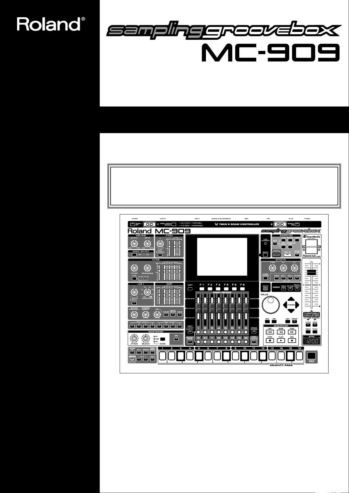
Thank you, and congratulations on your choice of the Roland MC-909 Sampling Groovebox.
201b
Convention Used in This Manual
• Words enclosed in square brackets indicate buttons or a dial or a knob or a slider on the panel.
• (p. **) indicates a reference page.
985
* The explanations in this manual include illustrations that depict what should typically be shown by the
display. Note, however, that your unit may incorporate a newer, enhanced version of the system (e.g., includes
newer sounds), so what you actually see in the display may not always match what appears in the manual.
202
Copyright © 2002 ROLAND CORPORATION
All rights reserved. No part of this publication may be reproduced in any form without the
written permission of ROLAND CORPORATION.
Page 2
WARNING: To reduce the risk of fire or electric shock, do not expose this apparatus to rain or moisture.
CAUTION
RISK OF ELECTRIC SHOCK
DO NOT OPEN
ATTENTION: RISQUE DE CHOC ELECTRIQUE NE PAS OUVRIR
CAUTION: TO REDUCE THE RISK OF ELECTRIC SHOCK,
DO NOT REMOVE COVER (OR BACK).
NO USER-SERVICEABLE PARTS INSIDE.
REFER SERVICING TO QUALIFIED SERVICE PERSONNEL.
The lightning flash with arrowhead symbol, within an
equilateral triangle, is intended to alert the user to the
presence of uninsulated “dangerous voltage” within the
product’s enclosure that may be of sufficient magnitude to
constitute a risk of electric shock to persons.
The exclamation point within an equilateral triangle is
intended to alert the user to the presence of important
operating and maintenance (servicing) instructions in the
literature accompanying the product.
INSTRUCTIONS PERTAINING TO A RISK OF FIRE, ELECTRIC SHOCK, OR INJURY TO PERSONS.
IMPORTANT SAFETY INSTRUCTIONS
SAVE THESE INSTRUCTIONS
WARNING - When using electric products, basic precautions should always be followed, including the following:
1. Read these instructions.
2. Keep these instructions.
3. Heed all warnings.
4. Follow all instructions.
5. Do not use this apparatus near water.
6. Clean only with a dry cloth.
7. Do not block any of the ventilation openings. Install in
accordance with the manufacturers instructions.
8. Do not install near any heat sources such as radiators,
heat registers, stoves, or other apparatus (including
amplifiers) that produce heat.
9. Do not defeat the safety purpose of the polarized or
grounding-type plug. A polarized plug has two blades with
one wider than the other. A grounding type plug has two
blades and a third grounding prong. The wide blade or the
third prong are provided for your safety. If the provided plug
does not fit into your outlet, consult an electrician for
replacement of the obsolete outlet.
10. Protect the power cord from being walked on or pinched
particularly at plugs, convenience receptacles, and the
point where they exit from the apparatus.
11. Only use attachments/accessories specified
by the manufacturer.
12. Unplug this apparatus during lightning storms or when
unused for long periods of time.
13. Refer all servicing to qualified service personnel. Servicing
is required when the apparatus has been damaged in any
way, such as power-supply cord or plug is damaged, liquid
has been spilled or objects have fallen into the apparatus,
the apparatus has been exposed to rain or moisture, does
not operate normally, or has been dropped.
For the U.K.
IMPORTANT: THE WIRES IN THIS MAINS LEAD ARE COLOURED IN ACCORDANCE WITH THE FOLLOWING CODE.
BLUE:
BROWN:
As the colours of the wires in the mains lead of this apparatus may not correspond with the coloured markings identifying
the terminals in your plug, proceed as follows:
The wire which is coloured BLUE must be connected to the terminal which is marked with the letter N or coloured BLACK.
The wire which is coloured BROWN must be connected to the terminal which is marked with the letter L or coloured RED.
Under no circumstances must either of the above wires be connected to the earth terminal of a three pin plug.
NEUTRAL
LIVE
2
Page 3
USING THE UNIT SAFELY
Used for instructions intended to alert
the user to the risk of death or severe
injury should the unit be used
improperly.
Used for instructions intended to alert
the user to the risk of injury or material
damage should the unit be used
improperly.
* Material damage refers to damage or
other adverse effects caused with
respect to the home and all its
furnishings, as well to domestic
animals or pets.
001
• Before using this unit, make sure to read the
instructions below, and the Owner’s Manual.
..........................................................................................................
002b
• Do not open or perform any internal modifications on the unit. (The only exception would be
where this manual provides specific instructions
which should be followed in order to put in place
user-installable options; see p. 142, p. 144, p. 146,
and p. 148.)
..........................................................................................................
003
• Do not attempt to repair the unit, or replace parts
within it (except when this manual provides
specific instructions directing you to do so). Refer
all servicing to your retailer, the nearest Roland
Service Center, or an authorized Roland
distributor, as listed on the “Information” page.
..........................................................................................................
004
• Never use or store the unit in places that are:
• Subject to temperature extremes (e.g., direct
sunlight in an enclosed vehicle, near a heating
duct, on top of heat-generating equipment); or
are
• Damp (e.g., baths, washrooms, on wet floors);
or are
• Humid; or are
• Exposed to rain; or are
• Dusty; or are
• Subject to high levels of vibration.
..........................................................................................................
007
• Make sure you always have the unit placed so it is
level and sure to remain stable. Never place it on
stands that could wobble, or on inclined surfaces.
..........................................................................................................
008a (Modified)
• The unit should be connected to a power source
only of the type described in the operating instructions, or as marked on the bottom of the unit.
..........................................................................................................
The symbol alerts the user to important instructions
or warnings.The specific meaning of the symbol is
determined by the design contained within the
triangle. In the case of the symbol at left, it is used for
general cautions, warnings, or alerts to danger.
The symbol alerts the user to items that must never
be carried out (are forbidden). The specific thing that
must not be done is indicated by the design contained
within the circle. In the case of the symbol at left, it
means that the unit must never be disassembled.
The ● symbol alerts the user to things that must be
carried out. The specific thing that must be done is
indicated by the design contained within the circle. In
the case of the symbol at left, it means that the powercord plug must be unplugged from the outlet.
008e
• Use only the attached power-supply cord.
..........................................................................................................
009
• Do not excessively twist or bend the power cord,
nor place heavy objects on it. Doing so can
damage the cord, producing severed elements and
short circuits. Damaged cords are fire and shock
hazards!
..........................................................................................................
010
• This unit, either alone or in combination with an
amplifier and headphones or speakers, may be
capable of producing sound levels that could
cause permanent hearing loss. Do not operate for
a long period of time at a high volume level, or at
a level that is uncomfortable. If you experience
any hearing loss or ringing in the ears, you should
immediately stop using the unit, and consult an
audiologist.
..........................................................................................................
011
• Do not allow any objects (e.g., flammable material,
coins, pins); or liquids of any kind (water, soft
drinks, etc.) to penetrate the unit.
..........................................................................................................
012a
• Immediately turn the power off, remove the
power cord from the outlet, and request servicing
by your retailer, the nearest Roland Service
Center, or an authorized Roland distributor, as
listed on the “Information” page when:
• The power-supply cord, or the plug has been
damaged; or
• If smoke or unusual odor occurs
• Objects have fallen into, or liquid has been
spilled onto the unit; or
• The unit has been exposed to rain (or otherwise
has become wet); or
• The unit does not appear to operate normally or
exhibits a marked change in performance.
..........................................................................................................
3
Page 4
013
• In households with small children, an adult
should provide supervision until the child is
capable of following all the rules essential for the
safe operation of the unit.
..........................................................................................................
014
• Protect the unit from strong impact.
(Do not drop it!)
..........................................................................................................
015
• Do not force the unit’s power-supply cord to share
an outlet with an unreasonable number of other
devices. Be especially careful when using
extension cords—the total power used by all
devices you have connected to the extension
cord’s outlet must never exceed the power rating
(watts/amperes) for the extension cord. Excessive
loads can cause the insulation on the cord to heat
up and eventually melt through.
..........................................................................................................
016
• Before using the unit in a foreign country, consult
with your retailer, the nearest Roland Service
Center, or an authorized Roland distributor, as
listed on the “Information” page.
..........................................................................................................
022a
• Always turn the unit off and unplug the power
cord before attempting installation of the circuit
board (SRX series/DIMM; p. 16).
..........................................................................................................
026
• Do not put anything that contains water (e.g.,
flower vases) on this unit. Also, avoid the use of
insecticides, perfumes, alcohol, nail polish, spray
cans, etc., near the unit. Swiftly wipe away any
liquid that spills on the unit using a dry, soft cloth.
..........................................................................................................
101a
• The unit should be located so that its location or
position does not interfere with its proper ventilation.
..........................................................................................................
102b
• Always grasp only the plug on the power-supply
cord when plugging into, or unplugging from, an
outlet or this unit.
..........................................................................................................
103a:
• At regular intervals, you should unplug the power
plug and clean it by using a dry cloth to wipe all
dust and other accumulations away from its
prongs. Also, disconnect the power plug from the
power outlet whenever the unit is to remain
unused for an extended period of time. Any
accumulation of dust between the power plug and
the power outlet can result in poor insulation and
lead to fire.
..........................................................................................................
104
• Try to prevent cords and cables from becoming
entangled. Also, all cords and cables should be
placed so they are out of the reach of children.
..........................................................................................................
106
• Never climb on top of, nor place heavy objects on
the unit.
..........................................................................................................
107b
• Never handle the power cord or its plugs with wet
hands when plugging into, or unplugging from,
an outlet or this unit.
..........................................................................................................
108a
• Before moving the unit, disconnect the power
plug from the outlet, and pull out all cords from
external devices.
..........................................................................................................
109a
• Before cleaning the unit, turn off the power and
unplug the power cord from the outlet (p. 16).
..........................................................................................................
110a
• Whenever you suspect the possibility of lightning
in your area, pull the plug on the power cord out
of the outlet.
..........................................................................................................
115a
• Install only the specified circuit board (SRX
series). Remove only the specified screws (p. 142,
p. 144, p. 146, and p. 148).
..........................................................................................................
118
• Should you remove screws, make sure to put them
in a safe place out of children’s reach, so there is
no chance of them being swallowed accidentally.
..........................................................................................................
4
Page 5

IMPORTANT NOTES
291b
In addition to the items listed under “IMPORTANT SAFETY INSTRUCTIONS” and “USING THE UNIT SAFELY” on pages 2
and 3, please read and observe the following:
Power Supply
301
• Do not use this unit on the same power circuit with any
device that will generate line noise (such as an electric
motor or variable lighting system).
307
• Before connecting this unit to other devices, turn off the
power to all units. This will help prevent malfunctions
and/or damage to speakers or other devices.
308
• Although the LCD and LEDs are switched off when the
POWER switch is switched off, this does not mean that the
unit has been completely disconnected from the source of
power. If you need to turn off the power completely, first
turn off the POWER switch, then unplug the power cord
from the power outlet. For this reason, the outlet into
which you choose to connect the power cord’s plug
should be one that is within easy reach and readily accessible.
Placement
351
• Using the unit near power amplifiers (or other equipment
containing large power transformers) may induce hum.
To alleviate the problem, change the orientation of this
unit; or move it farther away from the source of interference.
352a
• This device may interfere with radio and television
reception. Do not use this device in the vicinity of such
receivers.
352b
• Noise may be produced if wireless communications
devices, such as cell phones, are operated in the vicinity of
this unit. Such noise could occur when receiving or initiating a call, or while conversing. Should you experience
such problems, you should relocate such wireless devices
so they are at a greater distance from this unit, or switch
them off.
355
• To avoid possible breakdown, do not use the unit in a wet
area, such as an area exposed to rain or other moisture.
Maintenance
401a
• For everyday cleaning wipe the unit with a soft, dry cloth
or one that has been slightly dampened with water. To
remove stubborn dirt, use a cloth impregnated with a
mild, non-abrasive detergent. Afterwards, be sure to wipe
the unit thoroughly with a soft, dry cloth.
402
• Never use benzine, thinners, alcohol or solvents of any
kind, to avoid the possibility of discoloration and/or
deformation.
Additional Precautions
551
• Please be aware that the contents of memory can be
irretrievably lost as a result of a malfunction, or the
improper operation of the unit. To protect yourself against
the risk of loosing important data, we recommend that
you periodically save a backup copy of important data
you have stored in the unit’s memory on a memory card,
or in another MIDI device (e.g., a sequencer).
552
• Unfortunately, it may be impossible to restore the contents
of data that was stored in the unit’s memory, a memory
card, or another MIDI device (e.g., a sequencer) once it has
been lost. Roland Corporation assumes no liability
concerning such loss of data.
553
• Use a reasonable amount of care when using the unit’s
buttons, sliders, or other controls; and when using its jacks
and connectors. Rough handling can lead to malfunctions.
554
• Never strike or apply strong pressure to the display.
556
• When connecting / disconnecting all cables, grasp the
connector itself—never pull on the cable. This way you
will avoid causing shorts, or damage to the cable’s
internal elements.
557
• A small amount of heat will radiate from the unit during
normal operation.
558a
• To avoid disturbing your neighbors, try to keep the unit’s
volume at reasonable levels. You may prefer to use
headphones, so you do not need to be concerned about
those around you (especially when it is late at night).
559a
• When you need to transport the unit, package it in the box
(including padding) that it came in, if possible. Otherwise,
you will need to use equivalent packaging materials.
562
• Use a cable from Roland to make the connection. If using
some other make of connection cable, please note the
following precautions.
• Some connection cables contain resistors. Do not use
cables that incorporate resistors for connecting to this
unit. The use of such cables can cause the sound level
to be extremely low, or impossible to hear. For information on cable specifications, contact the manufacturer of the cable.
5
Page 6
IMPORTANT NOTES
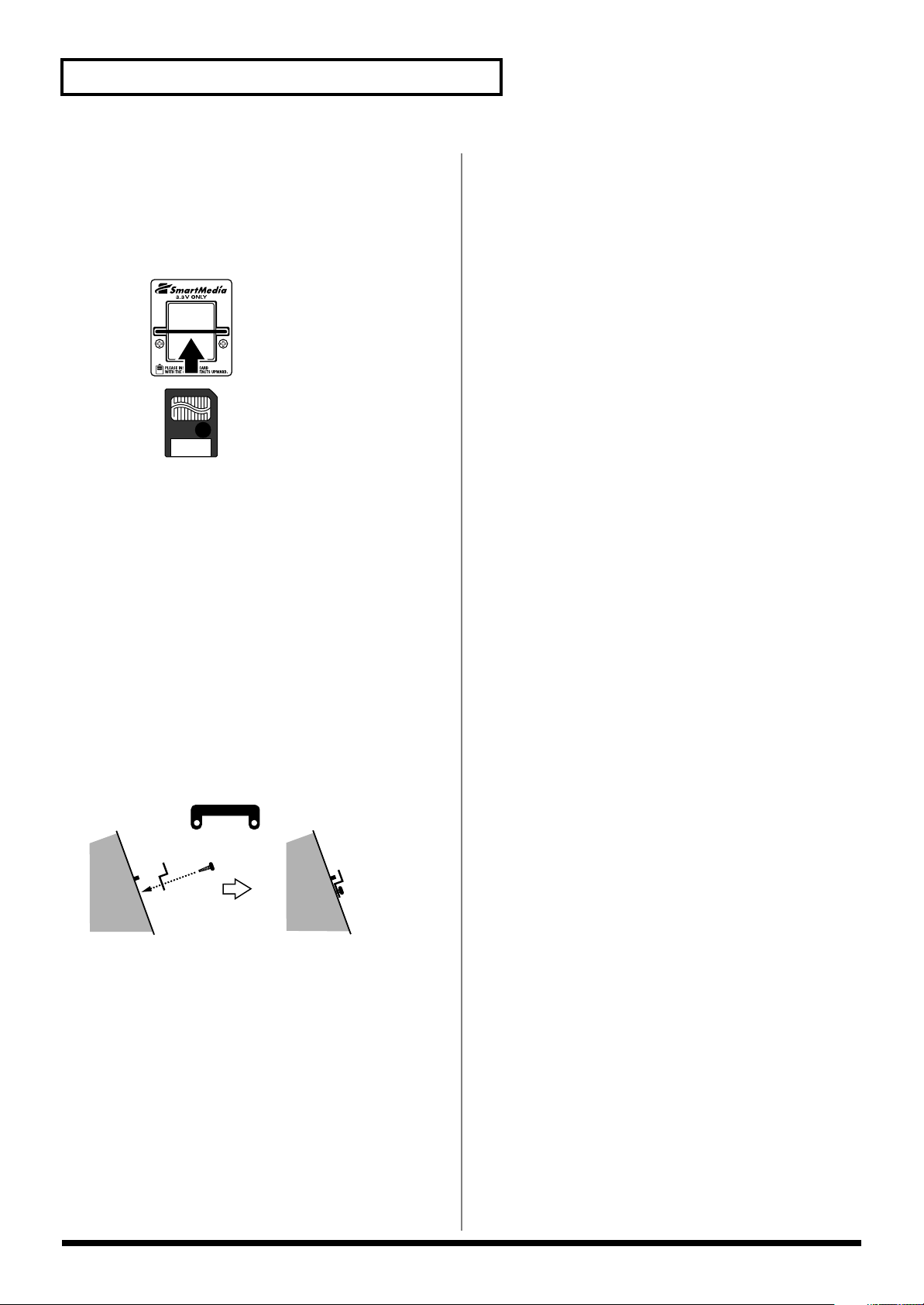
Before Using Memory Cards
Using Memory Cards
704
• Carefully insert the Memory card all the way in—until it is
firmly in place.
705
• Never touch the terminals of the Memory card. Also,
avoid getting the terminals dirty.
Installing the card protector
The MC-909 provides a card protector to prevent theft of the
memory card. To install the card protector, use the following
procedure.
Copyright
851
• Unauthorized recording, distribution, sale, lending, public
performance, broadcasting, or the like, in whole or in part,
of a work (musical composition, video, broadcast, public
performance, or the like) whose copyright is held by a
third party is prohibited by law.
852b
• When exchanging audio signals through a digital
connection with an external instrument, this unit can
perform recording without being subjected to some of the
restrictions of the Serial Copy Management System
(SCMS). This is because the unit is intended solely for
musical production, and is designed not to be subject to
restrictions as long as it is used to record works (such as
your own compositions) that do not infringe on the
copyrights of others. (SCMS is a feature that prohibits
second-generation and later copying through a digital
connection. It is built into MD recorders and other
consumer digital-audio equipment as a copyrightprotection feature.)
853
• Do not use this unit for purposes that could infringe on a
copyright held by a third party. We assume no responsibility whatsoever with regard to any infringements of
third-party copyrights arising through your use of this
unit.
1.
Use a screwdriver to remove both screws that are at
either side of the memory card slot.
2.
Insert the memory card into the memory card slot.
3.
Use the screws to fasten the card protector as shown
below.
Card protector
Side view
204
* Microsoft and Windows are registered trademarks of
Microsoft Corporation.
206j
* Windows® is known officially as: “Microsoft®
Windows® operating system.”
207
* Apple and Macintosh are registered trademarks of Apple
Computer, Inc.
209
* Mac OS is a trademark of Apple Computer, Inc.
230
* SmartMedia is a trademark of Toshiba Corp.
6
Page 7

Contents
USING THE UNIT SAFELY......................................................................3
IMPORTANT NOTES ...............................................................................5
Features of the MC-909 ........................................................................13
Panel Descriptions................................................................................14
Top Panel...................................................................................................................................................14
Rear Panel.................................................................................................................................................. 15
Getting Ready........................................................................................16
Making Connections ................................................................................................................................ 16
Turning On/Off the Power..................................................................................................................... 16
An Overview of the MC-909..................................................................17
Basic structure of the MC-909................................................................................................................. 17
The sound generator section .......................................................................................................17
The sequencer section...................................................................................................................17
The controller section ...................................................................................................................18
The sampler section ......................................................................................................................18
Adjusting the display contrast................................................................................................................ 18
Editing a value .......................................................................................................................................... 18
Quickly changing a value ............................................................................................................18
Saving your data....................................................................................................................................... 18
Regarding the locations where samples are stored............................................................................. 19
Restoring the factory settings (Factory Reset)...................................................................................... 20
Pattern Mode ............................... 21
How Things Work (in Pattern mode) ...................................................22
Playing a pattern ...................................................................................24
Basics of pattern play............................................................................................................................... 24
Basic playback operation ............................................................................................................. 24
Selecting a pattern to play back ..................................................................................................24
Changing the BPM (Tempo)........................................................................................................25
Turning the metronome (click) on/off....................................................................................... 25
Muting (silencing) a part.............................................................................................................. 26
Velocity pads............................................................................................................................................. 27
Pattern Call..................................................................................................................................... 27
RPS ..................................................................................................................................................28
Arpeggiator.................................................................................................................................... 30
Chord Memory.............................................................................................................................. 32
Realtime Modify section.......................................................................................................................... 33
Selecting the part whose sound you want to modify .............................................................. 33
Part Mixer .................................................................................................................................................. 33
Mix In .........................................................................................................................................................34
Directly outputting the sound of an external device ............................................................... 34
Playing various pitches using the sound of an external device ............................................. 34
Selecting the input source device................................................................................................ 34
D Beam Controller.................................................................................................................................... 35
SOLO SYNTH................................................................................................................................ 35
CUT + RESO (Cutoff + Resonance) ............................................................................................ 35
TURNTABLE ................................................................................................................................. 35
ASSIGNABLE (Other applications)............................................................................................ 35
7
Page 8

Contents
Turntable emulation................................................................................................................................. 36
Auto Sync................................................................................................................................................... 36
Effects ......................................................................................................................................................... 36
Mastering................................................................................................................................................... 36
Recording a pattern ..............................................................................37
Realtime recording ................................................................................................................................... 37
Recording procedure .................................................................................................................... 38
Rehearsal ........................................................................................................................................38
Realtime Erase ...............................................................................................................................39
Recording Cancel ..........................................................................................................................39
TR-REC....................................................................................................................................................... 39
Recording procedure .................................................................................................................... 40
About the timing scale.................................................................................................................. 40
Step recording........................................................................................................................................... 41
Recording procedure .................................................................................................................... 41
Tempo/mute recording........................................................................................................................... 42
Pattern editing.......................................................................................43
Basic procedure for pattern editing ....................................................................................................... 43
Extract a Rhythm Instrument...................................................................................................... 44
Pattern Copy .................................................................................................................................. 44
Erase................................................................................................................................................ 45
Delete Measure.............................................................................................................................. 45
Insert Measure ............................................................................................................................... 45
Transpose .......................................................................................................................................45
Change Velocity/Change Duration ...........................................................................................45
Shift Clock ...................................................................................................................................... 45
Data Thin........................................................................................................................................ 46
Edit Quantize................................................................................................................................. 46
Reclock............................................................................................................................................ 47
Microscope ................................................................................................................................................ 48
Basic procedure in the Microscope............................................................................................. 48
Performance data that can be edited in the Microscope ......................................................... 48
Inserting performance data (Create) .......................................................................................... 49
Erasing performance data (Erase)............................................................................................... 49
Moving performance data (Move).............................................................................................. 49
Copying performance data (Copy)............................................................................................. 49
Editing a system exclusive message........................................................................................... 49
Saving a pattern ....................................................................................50
Patch/Sample Mode .....................51
How Things Work (in Pattern mode) ...................................................52
Patch Edit ..............................................................................................54
How a Patch Is Organized ......................................................................................................................54
How a Tone Is Organized............................................................................................................ 54
Tips for Creating a Patch......................................................................................................................... 54
Selecting a patch/rhythm set.................................................................................................................. 55
Selecting from a list.......................................................................................................................55
Selecting directly ........................................................................................................................... 55
Selecting the Tone(s) That Will Sound ..................................................................................................56
8
Page 9

Contents
Patch editing procedure ..........................................................................................................................56
Editing from the Panel Knobs ..................................................................................................... 56
Detailed Editing............................................................................................................................. 56
Selecting a Tone to Edit................................................................................................................ 56
Rhythm Edit...........................................................................................70
How Percussion Instruments Are Organized ...................................................................................... 70
Selecting the Wave(s) That Will Sound................................................................................................. 70
Rhythm editing procedure...................................................................................................................... 70
Selecting the rhythm tone to edit................................................................................................ 70
Selecting the wave that you want to edit................................................................................... 70
Saving a Patch/Rhythm Set .................................................................77
Copying and Initializing a Patch/Rhythm Set.....................................78
Copying a Patch Tone.............................................................................................................................. 78
Initializing a Patch....................................................................................................................................78
Copying a Rhythm Tone (Key)............................................................................................................... 78
Initializing a Rhythm Set......................................................................................................................... 78
Song Mode................................... 79
How Things Work (in Song mode) ......................................................80
Playing songs........................................................................................82
Basic playback operation ............................................................................................................. 82
Song Reset ......................................................................................................................................82
Selecting a song to play................................................................................................................ 82
Changing the BPM or mute status.............................................................................................. 82
Recording a song..................................................................................83
Editing the setup parameters ......................................................................................................83
Song editing ..........................................................................................84
Clear All Steps ...............................................................................................................................84
Delete Step...................................................................................................................................... 84
Insert Step....................................................................................................................................... 84
Song Copy ...................................................................................................................................... 84
Saving a song........................................................................................85
Effects .......................................... 87
Effects ....................................................................................................88
Effect on/off.............................................................................................................................................. 88
Effect settings ............................................................................................................................................ 88
Effect connection (Effect Routing) ..............................................................................................88
Compressor.................................................................................................................................... 89
Multi-effects ................................................................................................................................... 90
Reverb............................................................................................................................................. 90
Realtime control of effects....................................................................................................................... 91
Selecting the effect that you want to control............................................................................. 91
9
Page 10

Contents
Multi-Effects List ...................................................................................92
Multi-Effects Types ..................................................................................................................................92
Multi-Effects Parameters......................................................................................................................... 92
Mastering effect ..................................................................................108
Sampling.................................... 109
How Things Work (in Sampling mode) .............................................110
Sampling procedure ...........................................................................112
Sampling.................................................................................................................................................. 112
Resampling.............................................................................................................................................. 112
Mix Sampling.......................................................................................................................................... 112
Auto Divide Sampling........................................................................................................................... 112
Solo Sampling .........................................................................................................................................112
Dividing a sample during sampling ........................................................................................113
Sample Edit .........................................................................................114
Basic sample editing procedure ...........................................................................................................114
Zoom In/Out...............................................................................................................................114
Setting the start/end points of the sample ......................................................................................... 115
Sample List .............................................................................................................................................. 115
Sample Parameters................................................................................................................................. 116
Truncate ................................................................................................................................................... 117
Create Patch............................................................................................................................................. 117
Chop ......................................................................................................................................................... 118
Procedure for dividing a sample ..............................................................................................118
Automatically dividing a sample (Auto Chop)...................................................................... 118
Auditioning the divided samples............................................................................................. 119
Create Rhythm........................................................................................................................................ 119
Emphasis.................................................................................................................................................. 120
Combine...................................................................................................................................................120
Edit Time Stretch .................................................................................................................................... 121
Normalize................................................................................................................................................121
Amp.......................................................................................................................................................... 122
Saving a sample..................................................................................123
Menu (in Sample Edit) ........................................................................124
Using the menu....................................................................................................................................... 124
Loading a sample ........................................................................................................................ 124
Loading all samples .................................................................................................................... 124
Importing WAV/AIFF data ...................................................................................................... 124
Deleting a sample........................................................................................................................ 124
Erasing a sample ......................................................................................................................... 124
10
Page 11

Contents
Menu .........................................125
System .................................................................................................126
Panel/Controller .................................................................................................................................... 127
Sequencer/MIDI.....................................................................................................................................127
Sound ....................................................................................................................................................... 129
Sampling.................................................................................................................................................. 129
D Beam..................................................................................................................................................... 130
System Information................................................................................................................................ 130
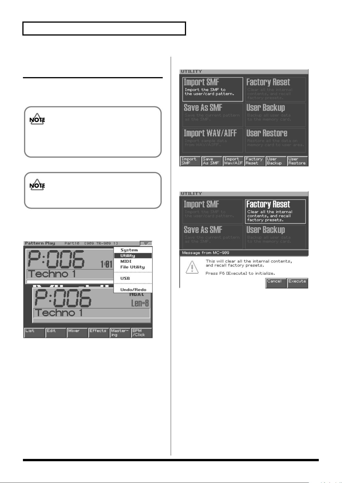
Utility ....................................................................................................131
Import SMF ............................................................................................................................................. 131
Save As SMF............................................................................................................................................ 132
Import WAV/AIFF ................................................................................................................................132
Factory Reset ........................................................................................................................................... 132
User Backup ............................................................................................................................................132
User Restore ............................................................................................................................................132
MIDI ......................................................................................................133
File Utility.............................................................................................134
Initializing a memory card (Format) ...................................................................................................134
Deleting a file (Delete) ...........................................................................................................................134
Moving a file (Move).............................................................................................................................. 134
Copying a file.......................................................................................................................................... 134
USB ......................................................................................................135
USB communication procedure ...........................................................................................................135
Canceling USB communication................................................................................................. 135
Cautions Regarding Folders and Files ................................................................................................135
Undo/Redo...........................................................................................136
V-LINK .......................................137
About V-LINK.......................................................................................138
What is V-LINK? ....................................................................................................................................138
Connection examples............................................................................................................................. 138
Using V-LINK ......................................................................................................................................... 138
Turning V-LINK on ....................................................................................................................138
Turning V-LINK off.................................................................................................................... 138
V-LINK settings......................................................................................................................................139
Resetting the image..................................................................................................................... 139
11
Page 12

Contents
Appendices ................................141
Installing the Wave Expansion Board...............................................142
Cautions When Installing a Wave Expansion Board ........................................................................142
How to Install a Wave Expansion Board ............................................................................................ 142
Checking that a wave expansion board is installed correctly.......................................................... 143
Installation de la carte d’extension Wave
(French language for Canadian Safety Standard) ...........................144
Précautions à prendre lors de l’installation d’une carte d’expansion Wave .................................144
Installation d’une carte d’expansion Wave ........................................................................................144
Vérifier que la carte d’expansion Wave est installée correctement................................................. 145
Expanding the Memory ......................................................................146
Precautions for Expanding Memory ................................................................................................... 146
How to Expand the Memory ................................................................................................................ 146
Removing the Memory............................................................................................................... 147
Checking that memory is installed correctly...................................................................................... 147
Ajouter de la mémoire
(French language for Canadian Safety Standard) ...........................148
Précautions à prendre lors de l’ajout de mémoire............................................................................. 148
Installation du module de mémoire ....................................................................................................148
Retrait du module de mémoire................................................................................................. 149
Vérifier que la mémoire est installée correctement ........................................................................... 149
Waveform List .....................................................................................150
Preset Patch List.................................................................................151
Preset Rhythm Set List.......................................................................154
Preset Pattern List ..............................................................................158
RPS Pattern List..................................................................................160
RPS Set List.........................................................................................162
Song List..............................................................................................165
Arpeggio Style List .............................................................................166
Chord Form List ..................................................................................167
SRX-05 Special Patch List..................................................................168
SRX-05 Special Rhythm Set List .......................................................169
MIDI Implementation Chart ................................................................170
Index.....................................................................................................172
Specifications......................................................................................175
Error Message List..............................................................................177
12
Page 13
Features of the MC-909
Cutting-edge groovebox that unifies
MIDI and sampling
In a single unit, the MC-909 delivers the power of a
conventional groovebox (an all-in-one synthesizer and
sequencer) plus a full-fledged sampler. It’s a new generation of
workstation that gives you everything you need to perfect your
music.
Built-in mastering functionality
A three-band compressor is built-in, letting you apply the
mastering operations that are the indispensable final step in
music production. The output of the MC-909 can be recorded
directly to CD or MD.
Sample synthesis
Waveforms sampled by the MC-909 or loaded from an external
source can be freely manipulated using the filter, LFO, and
effects in the same way as the internal preset waveforms.
Full-fledged sampler
The high-performance 44.1 kHz sampler provides five sampling
modes for various situations. You can sample external analog or
digital input sources, or resample the internal sounds. The full
range of editing functions includes Time Stretch and Chop.
Memory can be expanded to a maximum of 256 MB by adding
DIMM modules. When added to the internal 16 MB of RAM
(approximately 3 minutes of monaural sampling), this gives
you up to 272 MB (approximately 51 minutes of monaural
sampling).
High-performance synthesizer sound
generator
Features Roland's latest high-performance synthesizer sound
generator, with 800 patches and 64 rhythm sets that are based
on new waveforms created especially for the MC-909.
You can also install one wave expansion board (SRX series) to
increase the waveforms available to you when the need arises.
In particular, installing the SRX-05 “Supreme Dance” board will
let you use special patches and rhythm sets created specifically
for the MC-909.
Plenty of external interfaces
The MC-909 provides a USB connector for file transfer with
your computer. Waveform data files in .WAV or .AIFF formats
and SMF-format sequence data can be imported or exported
between the MC-909 and your computer with the click of a
mouse, as easily as if you were using an external drive.
Highly evolved turntable emulation,
and dual D Beam controllers
By automatically time-stretching a sample according to the
sequencer playback tempo, you can maintain playback
synchronization between the sequencer and samples. This lets
you use the turntable emulation slider to control the sequencer
and sample BPM in real time. You can also specify the variable
range of the slider.
In addition, the MC-909 features dual D Beam controllers,
located at the left and right of the panel. This gives you the
capability for special effects that have never been possible until
now.
Easy creation of original patterns
With a large LCD, knobs and a mixer section that can be
operated at any time to modify the sound directly, and newly
developed velocity pads, the MC-909 is an ideal recording
environment. You can use realtime, TR-REC, and step recording
methods, and manipulate your music with editing functionality
that goes well beyond previous grooveboxes.
The sequencer has also been upgraded, letting you create 16part patterns that are up to 998 measures long. SMF Convert
Load/Save functions ensure easy data exchange with other
sequencers.
Two multi-effects, a compressor, and
reverb
The two independent MFX units (multi-effects: MFX1 provides
38 types, MFX2 provides 47 types) provide a complete array of
effects that are ready to go whenever you need them. In
particular, MFX2 can produce long delays of up to four seconds.
The two-band compressor is a great way to power-up rhythm
instruments such kick drum. The acclaimed reverb from the XV
series is also provided.
MC-909
An Overview of the
The latest patterns for creative use
and immediate performance
For immediate playing or for use in your own compositions, the
MC-909 provides 215 preset patterns and 440 different RPS
patterns, covering a broad range of current dance styles,
including techno, trance, house, hiphop, and R&B.
V-LINK function
V-LINK ( ) is a function that provides for the
play of music and visual material. By using V-LINK-compatible
video equipment, visual effects can be easily linked to, and
made part of the expressive elements of a performance. By
connecting the MC-909 to the Edirol DV-7PR, you can switch
images in synchronization with music, or use the MC-909’s
knobs to control the brightness, color, or playback speed of the
images.
13
Page 14
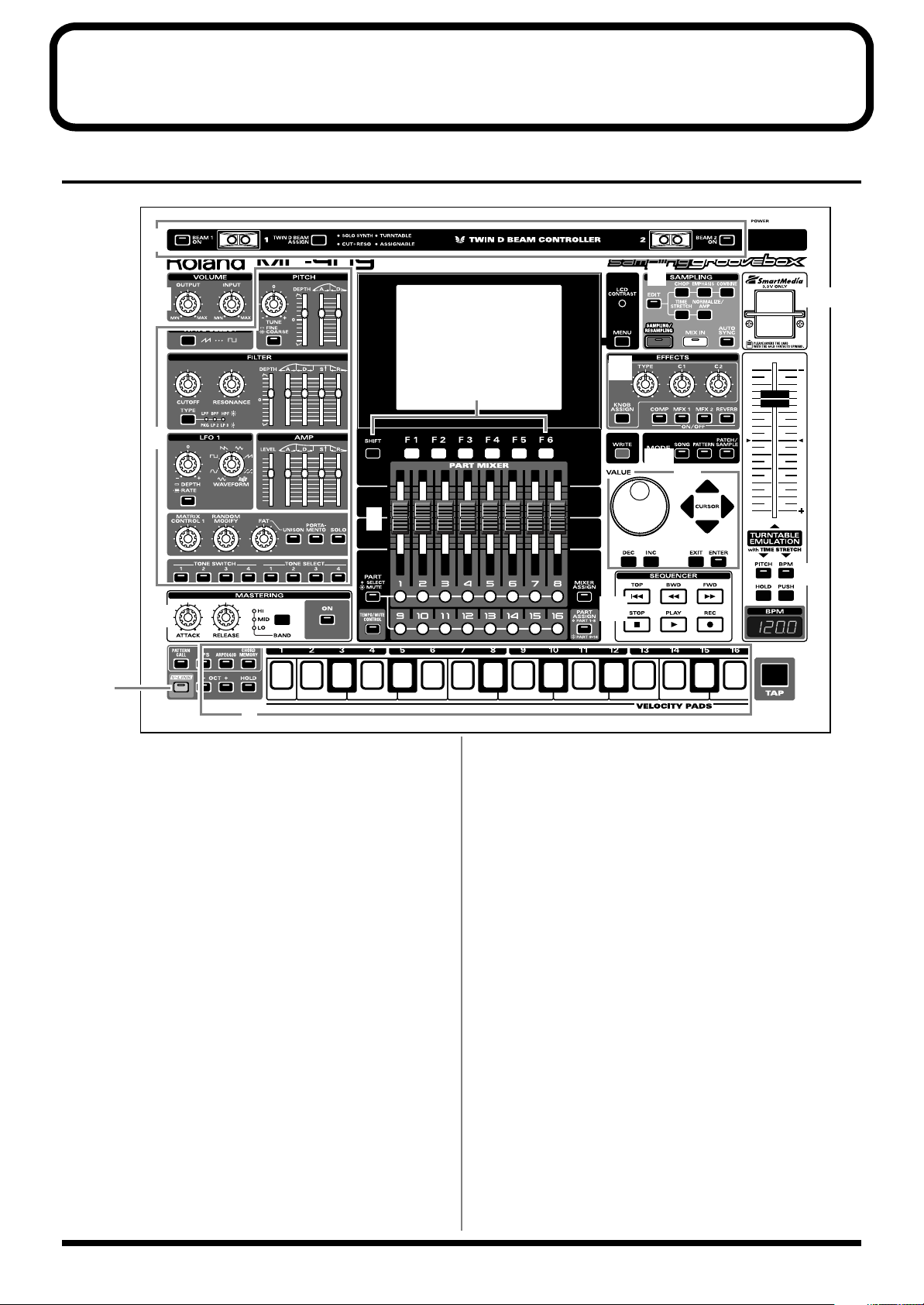
Panel Descriptions
1
2
3
4
5
6
7
8
9
12
13
14
10
11
15
16
Top Panel
fig.0-01
1. D Beam Controllers
You can modify the patterns or sounds by passing your hand over
these (p. 35).
2. Volume Section
Adjusts the output volume of the entire MC-909, and the input
volume to the MC-909.
3. Realtime Modify Section
Modifies the tone (p. 33).
4. Mastering Section
Applies a mastering effect (compressor) (p. 108).
5. Velocity Pads
Used as a keyboard to play sounds or trigger phrases (p. 27).
6. Function Buttons
Access the screens for the functions shown in the bottom line of the
screen.
7. Part Mixer Section
Adjusts the volume and pan for each part in the pattern (p. 33).
8. Sampling Section
Records external sounds into the MC-909 as waveforms, and
processes them (p. 109).
9. Effect Section
Applies special effects to the sound (p. 88).
10. Mode Section
Selects Song mode (p. 79), Pattern mode (p. 21), or Patch/Sample
mode (p. 51).
The button of the currently selected mode will light.
11. Cursor/Value Section
Used to select patterns or patches, and to input values (p. 18).
12. Sequencer Section
Used to play/record patterns or songs (p. 24, p. 82).
13. Turntable Emulation
Simulates the effect of changing the rotational speed of a turntable
(p. 36).
14. TAP Button
Adjusts the BPM (tempo) according to the timing at which you tap
this button (p. 25).
15. V-LINK Button
Switches V-LINK (p. 137) on/off.
16. SmartMedia card slot
Insert a SmartMedia card (3.3V, maximum 128 MB) here.
14
Page 15
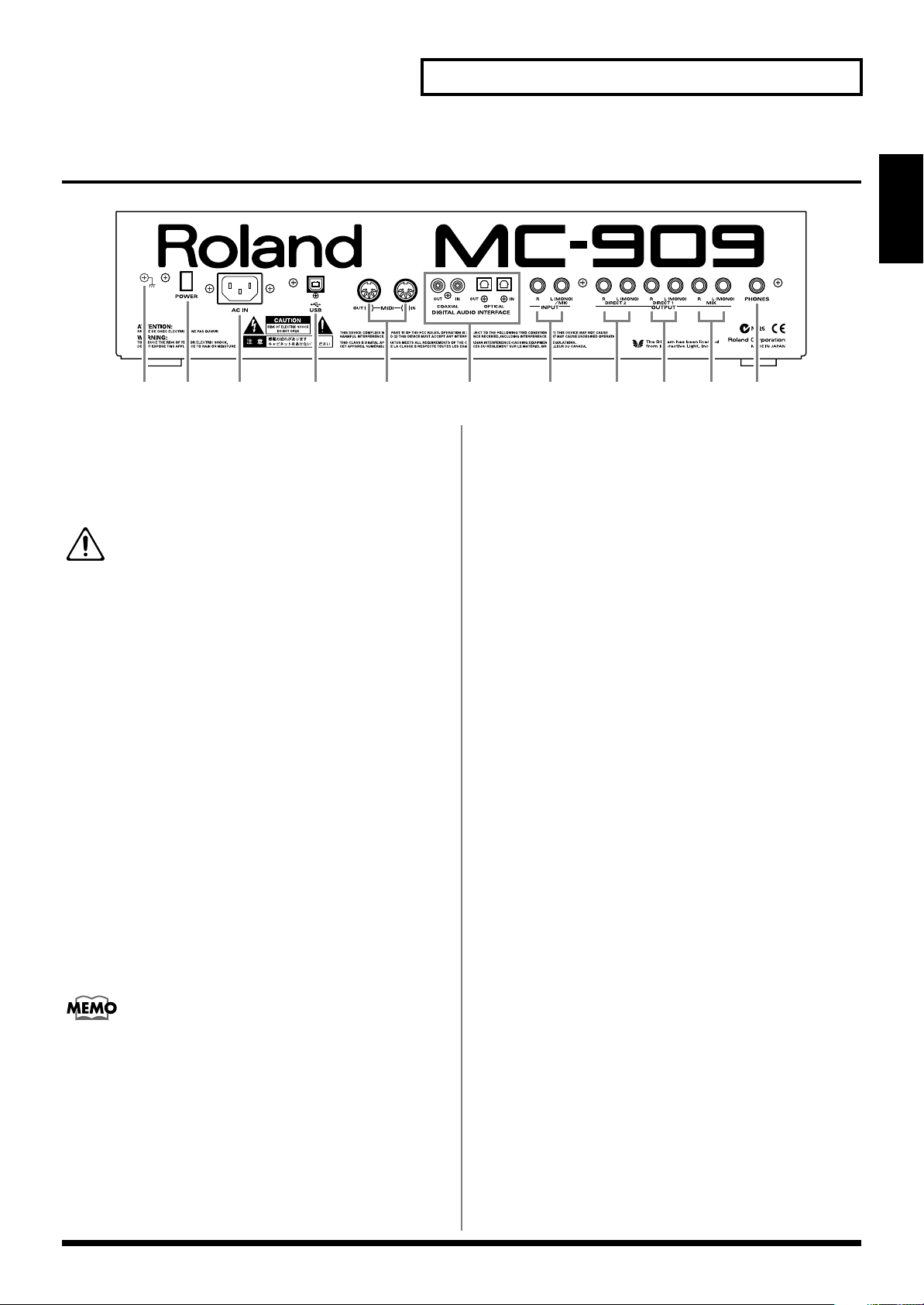
Rear Panel
fig.0-02
1 1011 2 3 4 6 785 9
Panel Descriptions
MC-909
An Overview of the
1. POWER Switch
Turns the MC-909’s power on and off (p. 16).
2. AC Inlet
Connect the included power cable here (p. 16).
The unit should be connected to a power source only of
the type marked on the bottom of the unit.
3. USB Connector
This connector lets you use a USB cable to connect your computer to
the MC-909 (p. 135).
4. MIDI Connectors (IN, OUT)
These connectors connect the MC-909 with other MIDI devices,
enabling the sending and receiving of MIDI messages (p. 16).
•
IN:
This connector receives messages from another MIDI device.
•
OUT:
This connector transmits messages to another MIDI
device.
5. Digital Audio Interface
These are optical-type and coaxial-type S/P DIF format digital in/
out connectors.
S/P DIF:
The digital output connectors output the same audio signal as is
output from the MIX OUTPUT jacks.
A digital interface format used in consumer digital audio
devices.
6. INPUT Jack
Accept input of audio signals in stereo (L/R) from external devices.
If you want to use mono input, connect to the L jack.
7. MIX OUTPUT Jacks
These jacks output stereo (L/R) audio signals to your amp or mixer.
If you want to use mono output, connect to the L jack.
8. DIRECT 1 OUTPUT Jacks
The sound of the part/patch/rhythm set/tone/rhythm tone whose
Output Assign (p. 88, p. 89, and p. 90) you set to “DIR1” is output in
stereo (L/R) from these jacks to your amp or mixer. If you want to
use mono output, connect to the L jack.
9. DIRECT 2 OUTPUT Jacks
The sound of the part/patch/rhythm set/tone/rhythm tone whose
Output Assign (p. 88, p. 89, and p. 90) you set to “DIR2” is output in
stereo (L/R) from these jacks to your amp or mixer. If you want to
use mono output, connect to the L jack.
10. PHONES Jack
Headphones are plugged in here (p. 16).
11. Ground Terminal
927
Depending on the circumstances of a particular setup, you may
experience a discomforting sensation, or perceive that the surface
feels gritty to the touch when you touch this device, microphones
connected to it, or the metal portions of other objects, such as guitars.
This is due to an infinitesimal electrical charge, which is absolutely
harmless. However, if you are concerned about this, connect the
ground terminal (see figure) with an external ground. When the unit
is grounded, a slight hum may occur, depending on the particulars
of your installation. If you are unsure of the connection method,
contact the nearest Roland Service Center, or an authorized Roland
distributor, as listed on the “Information” page.
When recording from a mic, connect it to the L jack, and set Input
Select (p. 34) to “MICROPHONE.”
Unsuitable places for connection
• Water pipes (may result in shock or electrocution)
• Gas pipes (may result in fire or explosion)
• Telephone-line ground or lightning rod (may be dangerous in
the event of lightning)
15
Page 16
Getting Ready
Mixer, etc.
Power amp
Speaker
(with built-in Amp)
MIDI IN
MIDI OUT
Stereo set, etc.
Stereo headphones
Make connections to
the MIX OUTPUT jacks
External MIDI device
(MIDI Keyboard, Sequencer, etc.)
to Power outlet
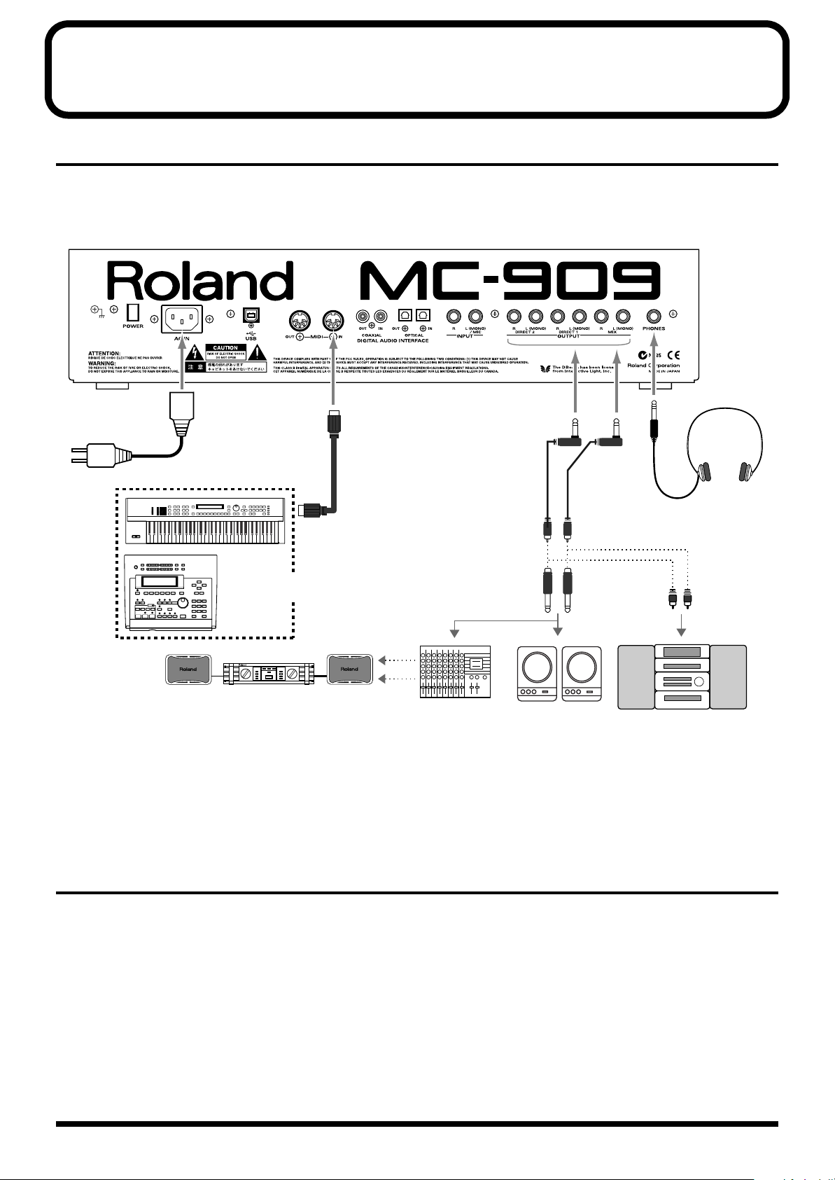
Making Connections
The MC-909 is not equipped with an internal amp or speakers. To
hear sound, you will need to connect it to a keyboard amp or audio
system, or connect headphones. Refer to the following figure when
connecting the MC-909 with external devices.
* To prevent malfunction and/or damage to speakers or other devices,
always turn down the volume, and turn off the power on all devices
before making any connections.
fig.Connect.e
1.
2.
Turning On/Off the Power
* Once the connections have been completed (p. 16), turn on power to
1.
2.
3.
4.
16
Before making any connections, confirm that power to all
devices has been turned off.
Connect the AC power cord included with the MC-909 to
the unit, then plug the other end into a power outlet.
your various devices in the order specified. By turning on devices in
the wrong order, you risk causing malfunction and/or damage to
speakers and other devices.
Make sure that all volume controls on the MC-909 and
connected devices are set to “0.”
Turn on the device connected to the INPUT Jacks.
Turn on the MC-909’s POWER switch.
Turn on the devices connected to the OUTPUT Jacks.
3.
Connect audio and MIDI cables as shown in the diagram.
If connecting headphones, plug the headphones into the
PHONES jack.
5.
Adjust the volume levels for the devices.
* This unit is equipped with a protection circuit. A brief interval (a few
seconds) after power up is required before the unit will operate
normally.
Turning Off the Power
Before switching off the power, lower the volume on each of the
devices in your system and then TURN OFF the devices in the
reverse order to which they were switched on.
* If you need to turn off the power completely, first turn off the POWER
switch, then unplug the power cord from the power outlet. Refer to
Power Supply
(p. 5).
Page 17

An Overview of the MC-909
Basic structure of the MC909
This section provides an overview of the sequencer section, sound
generator section, controller section, and sampler section, which
make up the main parts of the MC-909.
fig.0-03.e
Sampling
Sampler
Section
Sequencer
Section
Recording
Controller (Velocity Pad, Knob, etc.)
PLAY
The sound generator section
This is the section that actually generates the sound. It produces
sounds in response to data received from the MC-909’s Controller or
Sequencer sections. You can also play the sound generator by
sending it performance data from an external MIDI device.
Since the sound generator section of the MC-909 is able to play up to
64 notes simultaneously, it can easily handle multiple parts.
Song
Two or more patterns connected in the order of playback are
called a song.
In one song, you can register up to 50 patterns in the desired
order of playback.
Sound Generator
Section
Velocity Pad Play
Rhythm set
A rhythm set assigns a separate instrumental sound to each
note of the keyboard. These instrumental sounds are not played
as a scale. The MC-909 provides 64 preset rhythm sets.
(Example)
fig.0-04
SNARE
HI-HATCLAP
B3
KICK
Tones
Tones are the raw materials of sound that are combined to
create a patch. The MC-909 provides 693 different waveforms,
and two waveforms can be assigned to each tone. (Waveforms
can be assigned in stereo; one for L and one for R.)
You can install separately sold wave expansion boards (SRX
series) to add more waveforms, and sounds that you sample
can also be used as waveforms.
Effects
Effects let you apply a variety of special effects to patches or
rhythm sets. You can use four effects simultaneously:
compressor (an effect that makes the sound more consistent),
reverb (which adds reverberation), and two multi-effects (each
selectable from 47 types such as equalizer, overdrive, and
delay).
TOM CYMBALRIM
The sequencer section
A
sequencer
can play back the performance data that was recorded.
The MC-909 is a sequencer that plays back patterns and adds
changes to the playback method. This type of sequencer is referred
to as a
is a device that records musical performance data, and
pattern sequencer
.
MC-909
An Overview of the
Pattern
A pattern is 1–998 measures of performance data consisting of
sounds (patches or rhythm sets) for up to 16 parts.
The MC-909 provides 215 different preset patterns.
Part
A part corresponds to a single musician in a band or orchestra.
Since the MC-909 has sixteen parts, you can use sixteen
different patches or rhythm sets to play as many as sixteen
performances simultaneously.
Patch
A patch corresponds to a single instrument such as a piano or
guitar. A patch consists of up to four “tones.” The MC-909
provides 800 different patches, and you can enjoy an enormous
variety of sounds simply by choosing from these patches.
Recording/playing a performance
The MC-909 comes with 215 previously prepared patterns
(
preset patterns
easily.
You can also create your own original patterns, either by
modifying preset patterns or by creating a pattern from scratch.
). These preset patterns can be played back
Simultaneous playback of multiple parts
The MC-909 is able to play multiple sounds (patches)
simultaneously. For example, with the following part
configuration, you can simultaneously play drums, bass, piano
and guitar; and the resulting performance will sound like a
band.
Part 1
Part 2
Part 3
Part 10
Guitar
Bass
Piano
Rhythm (Drum) Set
17
Page 18

An Overview of the MC-909
Editing performance data
Unlike a cassette tape or MD, a sequencer records a
performance as musical data (not as sound). It’s easy to edit the
performance data to create your own original patterns.
The controller section
The “controllers” of the MC-909 are its velocity pads, D Beam
controllers, and the panel knobs and sliders. By operating these
controllers you can modify the performance and sound in various
ways.
Velocity pads
These pads function just like a music keyboard. They are also
used to trigger RPS (p. 28) and the arpeggiator (p. 30).
Normally, pad number 2 will be C4. The force with which you
strike a pad will control the velocity (dynamics) of the note.
D Beam controllers
By passing your hand over these controllers you can play or
modify sounds (p. 35).
Turntable emulation
These buttons and slider allow realtime synchronized
performance with sound sources such as a turntable, assisting
you with DJ performance (p. 36).
Realtime modify knobs
These knobs and sliders give you realtime control over sound
parameters such as filter cutoff frequency and resonance or LFO
speed.
The sampler section
A sampler is a device that captures sounds from a wave file or an
external source such as a CD.
On the MC-909, a sampled sound can be handled just like an internal
waveform of the sound generation section; you can change the pitch
of the sampled sound, apply a filter to it, or modify its envelope.
Adjusting the display contrast
Use the [LCD CONTRAST] knob located at the right of the display to
adjust the contrast.
Turn the knob toward the right to darken the screen, or toward the
left to lighten it.
Editing a value
Use the [VALUE] dial to make large changes in a value, or use the
[INC]/[DEC] buttons to change a value in steps of one. Your
changes will affect the value that is displayed in white characters
within a black frame in the screen. This location is called the
“cursor.” If a screen contains more than one value that can be edited,
use the [CURSOR] buttons to move the cursor to the value you want
to edit.
Quickly changing a value
• If you hold down [SHIFT] while you turn the [VALUE] dial, the
value will change more rapidly.
Key Repeat function
• The value will continue changing if you press and hold [INC] or
[DEC].
• The cursor will continue moving if you press and hold a
[CURSOR] key.
Turbo Repeat function
• The value will increase rapidly if you hold down [INC], then
press and hold [DEC].
• The value will decrease rapidly if you hold down [DEC], then
press and hold [INC].
• The cursor will move rapidly if you hold down a [CURSOR]
button and then press the opposite [CURSOR] button.
Saving your data
18
After editing settings or recording a performance, you must save
your data if you want to keep the results. If you turn off the power
without saving, your settings or recorded performance will be lost.
For details on saving your data, refer to the following pages.
•
Saving a pattern
•
Saving a Patch/Rhythm Set
•
Saving a song
•
Saving a sample
•
Saving a Pattern Set
•
Saving an RPS set
•
Saving an arpeggio style
•
Saving a chord form
Saving takes several seconds. Do not turn off the power until saving
is completed. Doing so may cause the MC-909 to malfunction.
(p. 50)
(p. 77)
(p. 85)
(p. 123)
(p. 27)
(p. 30)
(p. 32)
(p. 33)
Page 19
An Overview of the MC-909
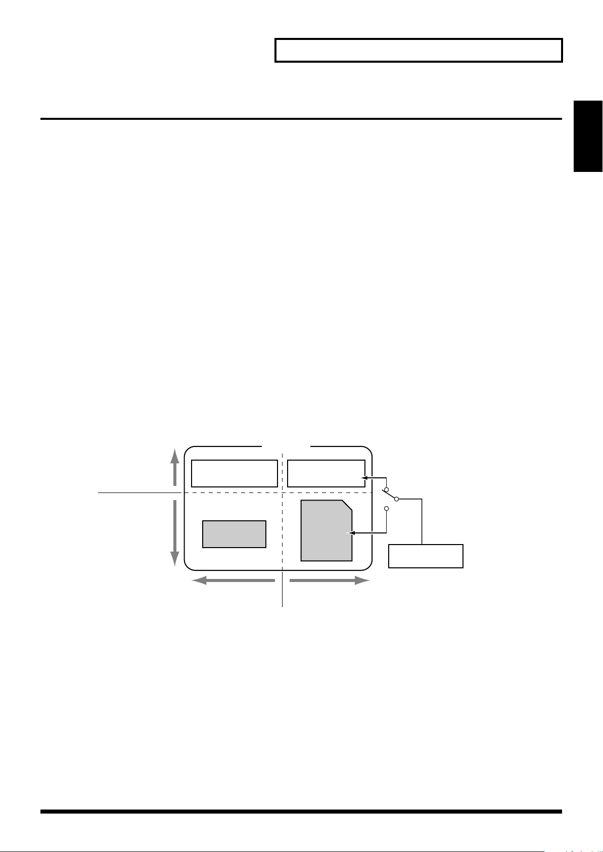
Regarding the locations where samples are stored
The MC-909 can use two types of memory; sample memory and DIMM whose contents are lost
when you turn off the power, and user area and memory card whose contents are preserved even
when the power is off.
When shipped from the factory, the MC-909 has 16 MB of sample memory and 16 MB of user
area. By adding a DIMM module you can expand the sample memory to a maximum of 272 MB
(if a 256 MB DIMM is used).
The user area can hold up to 16 MB, but by using a memory card you can store a maximum of 128
MB in addition to the user area.
When you record a sample on the MC-909 or play a patch that uses a sample, the sample is
loaded into sample memory (including the DIMM). However when you turn off the power,
the contents of the sample memory and DIMM will be lost. This means that if you want to
keep the sample, you must use the Write operation to save it in the user area or on a
memory card.
MC-909
An Overview of the
fig.SampleMem-e
When managing data from your computer or from the MC-909’s Utility menu, you can manage
only the data located in the user area or the memory card. You cannot manage data that is located
in sample memory or DIMM.
MC-909
Factory-installed
memory
Expandable
memory
For sampling and playback
(contents disappear when powered-off)
Be aware that because of this, the MC-909 can play samples larger than 128 MB, but
samples larger than 128 MB
Sample memory
16MB
DIMM
128 or 256MB
.
User area
16MB
USB
Memory
card
8–128MB
Computer
For saving and transfer to/from computer
(contents preserved even when powered-off)
cannot save
19
Page 20
An Overview of the MC-909
Restoring the factory settings (Factory Reset)
Here’s how to restore the settings of the MC-909 to their factory-set
state.
When you execute Factory Preset, the data of the internal user
memory will be lost. If the internal memory of the MC-909
contains data that you want to keep, you must save it on
SmartMedia or via USB to your computer.
Never turn off the power while Factory Reset is being
executed. Doing so may destroy the contents of memory.
3.
Press [ENTER] to access the Utility menu.
fig.0-06
4.
Press [F4 (Factory Reset)].
A warning message will appear.
fig.0-07
1.
Press [MENU].
2.
Use [CURSOR] to select “Utility.”
fig.0-05
5.
To execute a Factory Reset, press [F6 (Execute)].
The Factory Reset will be carried out.
* If you decide not to proceed with the reset, press [F5 (Cancel)].
When the screen indicates “Please Power Off,” turn the power off,
then on again.
20
Page 21

Pattern Mode
In this mode you can play, record, and edit patterns.
Pattern Mode
21
Page 22
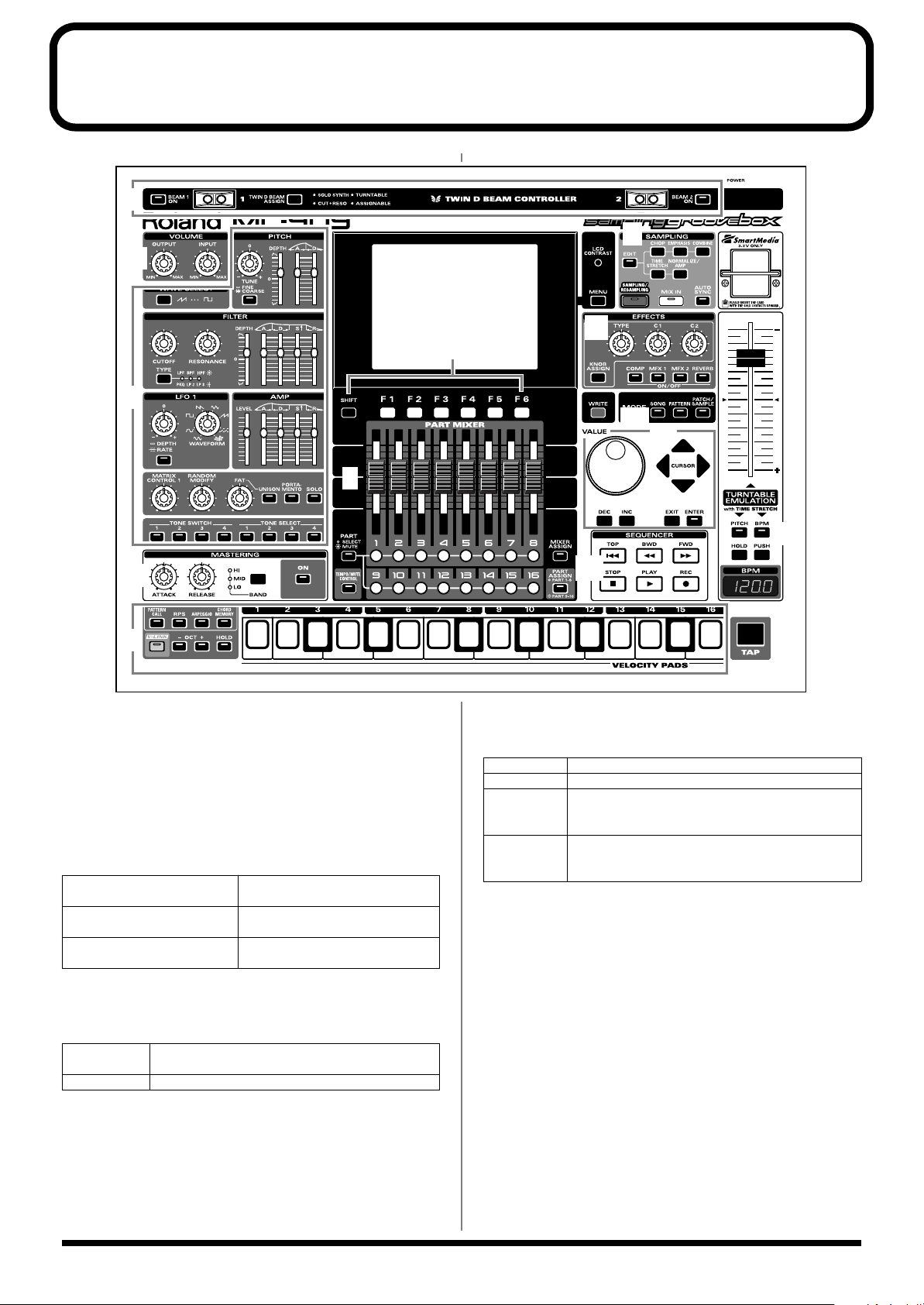
How Things Work (in Pattern mode)
1
2
3
4
5
6
7
8
9
12
13
14
10
11
fig.0-01
When you press the Mode section
indicator will light and the MC-909 will be in Pattern mode.
In Pattern mode, the various parts of the panel will perform the
following functions.
1. D Beam controllers
Pass your hand over these to modify the pattern (p. 35).
[PATTERN] button
, the button’s
[BEAM 1 ON]
[BEAM 2 ON] Turns the right D Beam controller
[TWIN D BEAM ASSIGN] Selects the function of the D Beam
2. Volume section
[OUTPUT] Adjusts the output volume of the MIX OUT jacks
and the headphone.
[INPUT] Adjusts the input volume from the INPUT jacks.
Turns the left D Beam controller
(BEAM 1) on/off.
(BEAM 2) on/off.
controller.
3. Realtime Modify section
These controls modify the sound (p. 33).
4. Mastering section
[ON] Switches the mastering effect (compressor) on/off.
[BAND] Selects the frequency band to adjust.
[ATTACK] Specify the time from when the volume goes up
the threshold level until the compressor effect applies.
[RELEASE] Specify the time from when the volume falls below
the threshold level until the compressor effect no
longer applies.
5. Velocity pads
Use these pads as a keyboard to play sounds or trigger phrases (p.
27).
6. Function buttons
These buttons access the function screens indicated in the bottom
line of the display.
22
Page 23
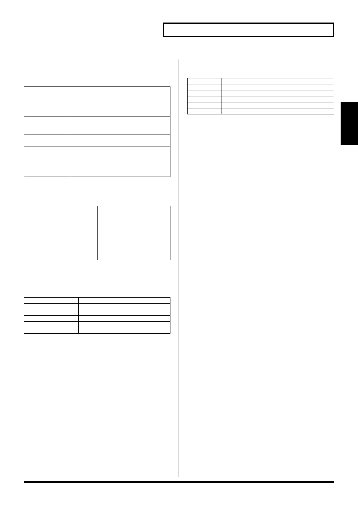
How Things Work (in Pattern mode)
7. Part Mixer section
Here you can adjust the volume, pan, etc., of each part (p. 33).
[PART]
(SELECT/MUTE)
[TEMPO/MUTE
CONTROL]
[MIXER ASSIGN] When you press this button so its indicator
[PART ASSIGN] Selects the parts that are controlled by the
Selects the function of the Part buttons [1]–
[16].
The buttons work as Part Select buttons
when the indicator is not lighted, and as
Mute buttons when the indicator is lit.
Switches on/off the Tempo/Mute part (a
part that records tempo changes and mute
operations, p. 42).
lights, the Mixer screen will appear.
sliders.
The sliders will control parts 1–8 if this indicator is not lighted, or parts 9–16 if the indicator is lit.
8. Sampling section
[EDIT] Displays the Sample Edit
screen (p. 114).
[SAMPLING/RESAMPLING] Displays the Sampling menu
screen (p. 112).
[MIX IN] Mixes the sound from the IN-
PUT jack into the output (p.
34).
[AUTO SYNC] Synchronizes a sample to the
pattern (p. 36).
12. Sequencer section
[PLAY] Plays a pattern (p. 24).
[STOP] Stops playback/recording.
[FWD] Advances to the next measure.
[BWD] Returns to the previous measure.
[TOP] Moves to the beginning of the pattern.
[REC] Used when recording (p. 37).
13. Turntable emulation
Applies an effect that simulates increasing/decreasing the rotational
speed of a turntable (p. 36).
14. TAP button
Lets you set the BPM (tempo) by pressing the button at the desired
timing (p. 25).
Pattern Mode
9. Effect section
Applies special effects to the sound (p. 88).
[COMP]–[REVERB] Switch each effect on/off (p. 88).
[KNOB ASSIGN] Selects the effect to be controlled in real
[TYPE] Selects the type of effect.
[C1], [C2] Modifies the assigned function in real
time (p. 91).
time.
10. Mode section
Press the [PATTERN] button to enter Pattern mode.
Pressing one of the other two buttons will switch you to the
corresponding mode.
11. Cursor/Value section
Use these buttons and dial to select patterns or input values (p. 18).
23
Page 24
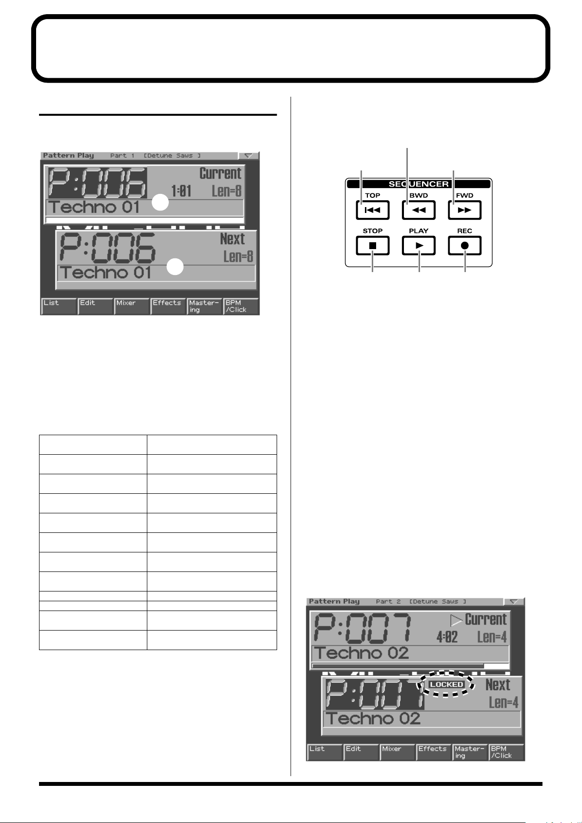
Playing a pattern
Basics of pattern play
The top screen of Pattern mode
fig.1-01
1
2
1.
Current pattern
The pattern that is now playing
2.
Next pattern
The pattern that will play next
* “Len” is the number of measures (Length) of the pattern.
Basic playback operation
Use the following buttons to control the playback.
fig.1-02.e
Return to the previous measure
Move to the beginning
of the pattern
Play back Used for recordingStop playback
* The [FWD], [BWD], and [TOP] buttons can also be used during
playback.
* * Press [STOP] twice to return to the beginning of the pattern.
Advance to the
next measure
Selecting a pattern to play back
There are two ways to select a pattern for playback;
a list
.
directly
, or
from
Function buttons
[F1 (List)]
(Pattern List)
[F2 (Edit)]
(Pattern Edit)
[F3 (Mixer)]
(Part Mixer)
[F4 (Effects)] Apply special effects to the sound
[F5 (Mastering)] Make settings for the Mastering ef-
[F6 (BPM/Click)] Set the tempo, and turn the metro-
[SHIFT] + [F1 (Arp)]
(Arpeggiator)
[SHIFT] + [F2 (Chord Memory)]
[SHIFT] + [F3 (Pattern Call)] Select a pattern set (p. 27).
[SHIFT] + [F4 (RPS)] Make RPS settings (p. 29).
[SHIFT] + [F5 (System)]
(System Edit)
[SHIFT] + [F6 (Utility)]
(Utility Menu)
Select a pattern from a list (p. 25).
Edit the settings of a pattern (p.
43).
Specify the volume, pan, etc., of
each part (p. 33).
(p. 88).
fect (p. 108).
nome on/off (p. 25).
Make arpeggiator settings (p. 30).
Register chords (p. 32).
Make settings that apply to the entire MC-909 (p. 126).
Open the Utility menu (p. 131).
Selecting a pattern directly
Selecting the current pattern
While the pattern is stopped, use [VALUE] or [INC/DEC] to select a
pattern.
Selecting the next pattern
While the pattern is playing, use [VALUE] or [INC/DEC] to select a
pattern.
When the current pattern finishes playing, the selected pattern
will start playing.
* Shortly before the current pattern finishes playing, the word
“LOCKED” will appear above the name of the next pattern. You will
not be able to change the next pattern while this is displayed, since
preparations are being made to move to that pattern.
fig.1-03
24
Page 25
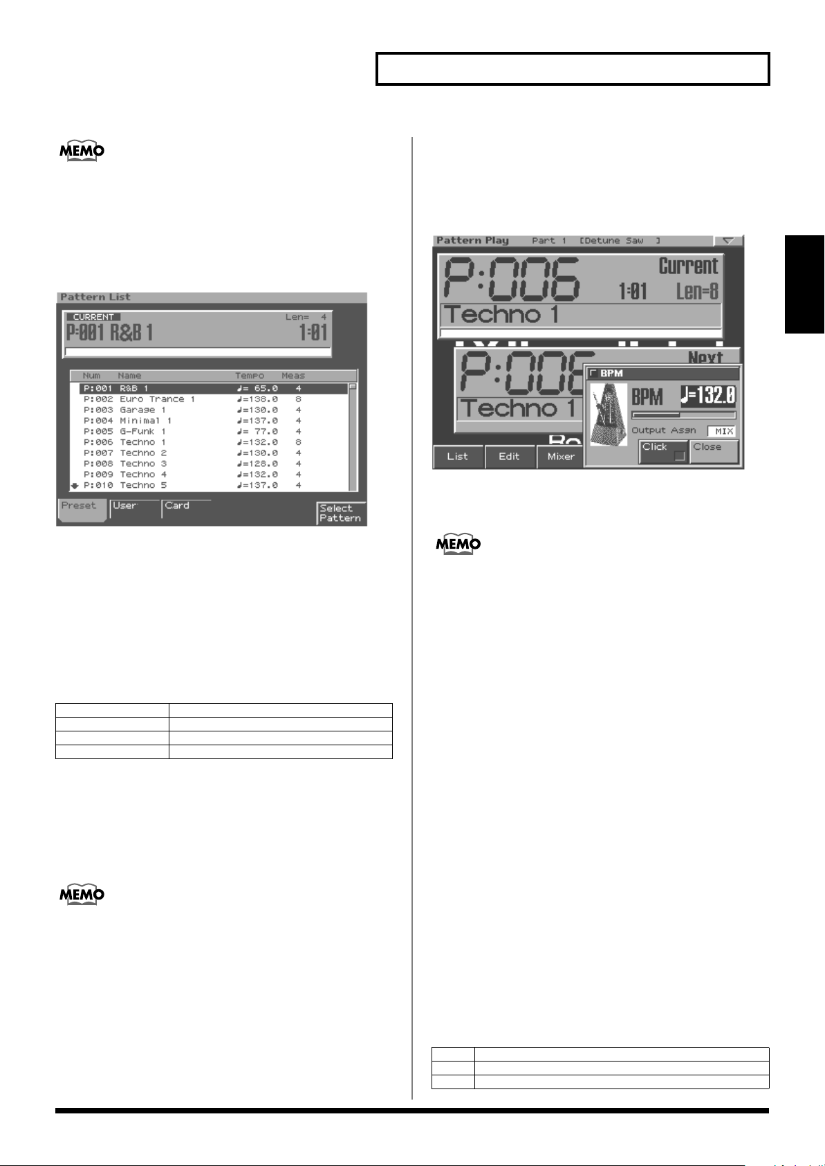
If you press [CURSOR (left/right)] while a pattern is playing, the
pattern will change immediately, and will start playing from the
beginning of the pattern.
Selecting a pattern from the list
1.
Press [F1 (List)].
fig.1-04
Playing a pattern
Changing the BPM (Tempo)
Using the [VALUE] dial
1.
Press [F6 (BPM/Click)] to access the BPM window.
fig.1-05
Pattern Mode
2.
Press [F1 (Preset)], [F2 (User)], or [F3 (Card)] to
choose the group that contains the desired pattern.
3.
Use [VALUE], [INC/DEC] or [CURSOR (up/down)] to
select a pattern.
If you hold down [SHIFT] while using the above controls, the
pattern number will change in steps of ten.
4.
Press [F6 (Select Pattern)] to finalize your selection.
[F1 (Preset)]
[F2 (User)] Choose user patterns.
[F3 (Card)] Choose patterns stored on a memory card.
[F6 (Select Pattern)] Finalize the selected pattern.
Choose preset patterns.
BPM (tempo) when playing patterns
successively
Each pattern has its own specified tempo (BPM). If you play back
patterns successively, the tempo will also change when the pattern
changes.
2.
Use [VALUE] or [INC/DEC] to set the BPM.
3.
Press [F6 (Close)] to close the BPM window.
You can access the BPM window during TR-REC by pressing
[SHIFT]+[F6], or during sampling by pressing [F4].
Using the TAP button
Press [TAP]
desired BPM.
* If desired, you can set the BPM by pressing [TAP] at eighth-note/
three or more times
sixteenth-note intervals (Tap Resolution ->p. 127).
at
quarter-note intervals
of the
Turning the metronome (click) on/off
1.
Press [F6 (BPM/Click)] to access the BPM window.
2.
Press [F5 (Click)] to select on or off.
When on, the “✔” will be displayed.
3.
Press [F6 (Close)] to close the BPM window.
* The metronome volume adjustment is a System setting (Metronome
Level -> p. 117)
If desired, you can maintain the tempo of the first-played pattern
even while switching patterns (BPM Lock ->p. 128).
Selecting the metronome output
destination
1.
Press [F6 (BPM/Click)] to access the BPM window.
2.
Press [CURSOR (up/down)] to move the cursor to
“Output Asgn.”
3.
Use [VALUE] or [INC/DEC] to select the output
destination.
MIX
DIR1
DIR2
Output from the MIX OUT jacks and the headphones.
Output from the DIRECT 1 OUTPUT jacks.
Output from the DIRECT 2 OUTPUT jacks.
25
Page 26
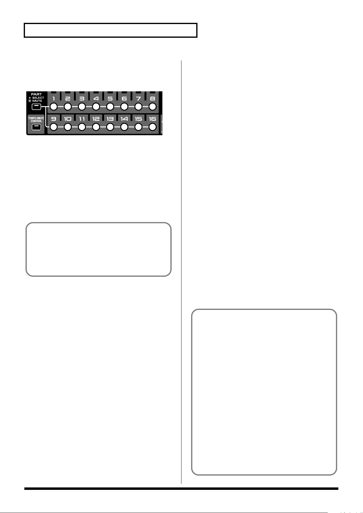
Playing a pattern
The indicators of the part buttons show the muted state of the
parts as follows:
• Lit: The part can be played.
•
Blinking: The part is muted.
•
Not lit: No performance has been recorded in the part. (The
indicator will light when you record data.)
Muting (silencing) a part
A pattern contains sixteen parts. You can mute (silence) each part in
real time.
fig.1-06
1.
In the Part Mixer section, press [PART] (SELECT/
MUTE) so the indicator is lighted.
Part buttons [1]–[16] now control part muting.
2.
Press the button of the part that you want to mute,
making it blink.
That part will be muted.
3.
To cancel muting, press the button of the muted part
once again, making it light.
All Parts Mute
This function mutes all parts at once.
1.
Hold down [SHIFT] and press [PART ASSIGN].
The sound of all parts will be muted.
All Parts On
This function un-mutes all parts at once.
1.
Hold down [SHIFT] and press [MIXER ASSIGN].
Muting will be cancelled for all parts, so they are all allowed to
play.
Mute Reverse
This function inverts the currently muted and currently playing
parts.
1.
Hold down [SHIFT] and press [TEMPO/MUTE
CONTROL].
The status of parts that are currently muted changes, so they are
allowed to play, while the parts that are currently playing will
be muted.
Mute Remain
This function maintains the mute status of each part while the next
pattern plays. For example, this lets you play the next pattern
without sounding the rhythm part.
1.
During pattern playback, press [PLAY].
The screen will indicate “MUTE REMAIN.”
2.
Select the next pattern.
After a time, the selected pattern will play, with the mute
settings of each part remaining as they were.
When the pattern changes, the Mute Remain function will
automatically be cancelled.
* Mute Remain will be cancelled if you press [PLAY] once again before
the pattern changes.
Solo
This function assigns play-ready status to one specified part, muting
the others.
1.
Hold down [SHIFT] and press the part button [1]–[16]
of the part you want to play.
All parts other than the selected part will be muted.
26
Default Mute
This function restores the part mute settings to the state stored in the
pattern.
1.
Hold down [SHIFT] and press [PART] (SELECT/
MUTE).
The part mute settings will return to the state stored in the
pattern.
About the setup parameters
On the MC-909, the following parameters allow their settings to
be individually stored for each pattern. These parameters are
collectively called the “setup parameters.”
• BPM (Tempo) (p. 25)
• Patch/Rhythm set * (p. 55)
• Part Level * (p. 33)
• Part Pan * (p. 33)
• Part Key Shift * (p. 33)
• Part Reverb Level * (p. 33)
• Part Output Assign * (p. 55)
• Sequencer Output Assign * (p. 55)
• Reverb settings (p. 90)
• Compressor settings (p. 89)
• Multi-effect settings (p. 90, p. 92)
• Part mute status * (p. 26)
• Auto Sync on/off * (p. 36)
* The asterisk indicates parameters that can be set for each part.
Page 27
Playing a pattern
Velocity pads
These pads work just like a keyboard. They can also be used to play
RPS and the arpeggiator. Normally, pad number 2 will be C4. The
force with which you strike the pads will vary the dynamics
(velocity) of the sound.
You can also set velocity to a fixed value (Pad Velocity ->p. 127).
[HOLD] If you press this button so its indicator lights,
the sound will still be heard even after you
take your finger off the velocity pad. The
sound will stop when you press [HOLD]
once again, extinguishing the indicator.
[OCT -]/[OCT +] These buttons shift the range of the velocity
pads in steps of one octave (maximum +/-4
octaves).
If you press both buttons simultaneously,
the octave shift will be reset to 0.
Various ways to use the velocity pads
[PATTERN CALL] The pads will recall patterns (Pattern
Call, p. 27).
[RPS] The pads will trigger phrases (RPS, p.
28).
[ARPEGGIO] The pads will play arpeggios (Arpeggia-
tor, p. 30).
[CHORD MEMORY] Produce chords by pressing a single pad
(Chord Memory, p. 32).
Registering a pattern in a Pattern Set
1.
Select the pattern you want to register, so it is the
current pattern.
2.
Select the pattern set into which you want to register
that pattern.
3.
Hold down [PATTERN CALL], and press the velocity
pad to which you want to register the pattern.
That pattern will be registered to the pad you pressed.
Saving a Pattern Set
Pattern Set settings that you have edited will be lost when you turn
off the power. If you want to keep your changes, you must save
them as follows.
1.
Hold down [PATTERN CALL] and press [F6 (PtnCall
Setting)].
Alternatively, hold down [SHIFT] and press [F3 (Pattern Call)].
The Pattern Call editing screen will appear.
2.
Use [VALUE] or [INC/DEC] to select the pattern set
that you want to save.
3.
Press [WRITE].
The Write menu screen will appear.
Make sure that “Pattern Set” is highlighted.
4.
Press [ENTER] or [F4 (PCL)].
Pattern Mode
Pattern Call
You can use the sixteen velocity pads as buttons to select patterns.
The patterns that are registered to each of the sixteen velocity pads
are handled as one “pattern set.” You are free to edit the contents of
a pattern set, and can store 50 different sets. You can also switch
between pattern sets during pattern playback.
You can use this method to select either the current pattern or the
next pattern.
* Pattern Call cannot be used in Song mode.
Using Pattern Call
1.
Press [PATTERN CALL] so its indicator is lighted.
2.
Press one of the velocity pads [1]–[16].
The pattern that is registered to the pad you pressed will be
selected.
* [HOLD] and [OCT +/-] will have no effect.
* Pattern Call cannot be used simultaneously with RPS, arpeggiator, or
chord memory.
5.
Assign a name to the pattern set.
For details on how to assign a name, refer to “Saving a pattern”
(p. 43).
6.
When you finish inputting the name, press [F6
(Write)].
A message will ask you for confirmation.
7.
To save the pattern set, press [F6 (Execute)].
* To cancel without saving, press [F5 (Cancel)].
Patterns that are registered in a pattern set allow you to specify setup
parameters that are different than in conventional pattern mode.
Selecting a pattern set
1.
Hold down [PATTERN CALL] and use [VALUE] or
[INC/DEC] to select a set.
27
Page 28
Playing a pattern
<Note when assigning RPS>
* It is not possible for multi-part phrases to be assigned to each of
the velocity pads. You must mute all parts other than the part
that contains the phrase you wish to assign. If you attempt to
assign a phrase in which two or more parts are un-muted, the
display will indicate “Cannot Assign Phrase!”.
* If you have assigned a phrase from a user pattern to RPS, and
modify the performance data of the pattern that contains that
phrase after it has been assigned, be aware that the phrase played
by RPS will be affected by these modifications. For example if you
delete the performance data of a pattern that contains an assigned
phrase, no sound will be heard when you use RPS to play that
phrase.
* If you assign a phrase from a part that uses MFX, the MFX
settings during RPS playback will be determined by the MFX
settings of the currently selected pattern. This means that the
RPS playback may sound different than the original phrase.
RPS
Any phrase that’s been assigned to one of the sixteen velocity pads
will continue playing as long as you hold down its pad.
The phrases that are registered to the sixteen velocity pads are
handled as one “RPS set.” You are free to edit the contents of an RPS
set, and can store 50 different sets. You can also switch between RPS
sets during pattern playback.
Using RPS
1.
Press [RPS] so its indicator is lighted.
2.
Press one of the velocity pads [1]–[16].
The phrase that is registered to the pad you pressed will
continue playing.
* [OCT +/-] will have no effect.
* RPS cannot be used simultaneously with pattern call, arpeggiator, or
chord memory.
RPS Hold
You can make a phrase continue playing even after you release your
finger from the velocity pad.
• To hold all phrases
Registering a phrase in an RPS set
1.
Select the pattern that contains the phrase you want
to register, so it is the current pattern.
2.
Mute all parts other than the single part you want to
register in RPS.
Refer to p. 26 for details on muting.
You may find it convenient to use the Solo function (p. 26).
3.
Select the RPS set in which you want to register that
phrase.
4.
Hold down [RPS], and press the velocity pad to
which you want to register the phrase.
That phrase will be registered to the pad you pressed.
1.
Press [HOLD] so the indicator is lit.
2.
Press a velocity pad to play a phrase.
You can stop that phrase by pressing the same pad once again.
• To hold individual phrases
1.
Hold down [HOLD] and press a velocity pad to play a
phrase.
[HOLD] will blink, and that phrase will continue playing until
you press the same pad once again.
2.
To play a phrase that you want to hold, hold down
[HOLD] and press the appropriate pad, as described
in step 1.
The phrases will play together.
3.
To play a phrase that you do not want to hold, press
only the appropriate pad.
When you release your finger from the pad, that phrase will
stop playing.
* In steps 1 and 2, you can also press [HOLD] while pressing the
velocity pad to play the phrase, as an alternative to holding down
[HOLD] and then pressing the pad.
To stop all phrases, press [HOLD] so the indicator goes out.
Selecting an RPS set
1.
Hold down [RPS] and use [VALUE] or [INC/DEC] to
select a set.
28
Patterns that are registered in an RPS set allow you to specify setup
parameters that are different than in conventional pattern mode.
Page 29
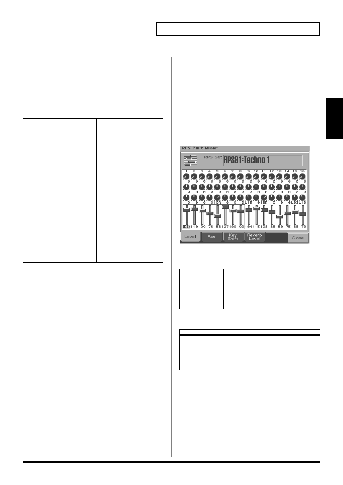
Playing a pattern
RPS Settings
1.
Hold down [RPS] and press [F6 (RPS Setting)].
Alternatively, hold down [SHIFT] and press [F4 (RPS)].
The RPS setting screen will appear.
2.
Use [CURSOR (up/down)] to select a parameter.
3.
Use [VALUE] or [INC/DEC] to edit the parameter.
Parameter
RPS Set
RPS Part Part 1–16 RPS part to edit
RPS Part Patch
Bank
RPS Part Patch
Number
RPS Part Output
Select
Remote Keyboard Switch
Range Explanation
01–50 RPS set to edit
— Patch assigned to RPS part
—
DRY, MFX1,
MFX2,
COMP,
DIR1, DIR2,
RHY
OFF, ON Refer to p. 128.
How the original sound of
each part will be output
DRY:
Output to MIX OUTPUT jacks without passing
through effects
MFX1 (2):
multi-effects 1 (or 2)
COMP:
the compressor
DIR1 (2):
RECT 1 (or DIRECT 2)
jacks without passing
through effects
RHY:
the settings of the rhythm
set assigned to the part
Output through
Output through
Output to the DI-
Output according to
Adjusting the settings of the RPS parts
RPS playback uses dedicated RPS parts that are separate from
conventional pattern playback. The patterns that are assigned to
velocity pads [1]–[16] will play RPS parts 1–16.
Here's how to adjust the settings of these RPS parts.
1.
Hold down [RPS] and press [F6 (RPS Setting)].
Alternatively, hold down [SHIFT] and press [F4 (RPS)].
The RPS setting screen will appear.
2.
Press [F3 (RPS Mixer)].
The RPS Mixer screen will appear.
3.
Use the part mixer section to adjust the volume, pan,
etc. of RPS parts 1–16.
Pattern Mode
<RPS Trigger Quantize>
When using RPS during pattern playback, patterns and phrases may
not play back in precise alignment, depending on the timing at
which you press the velocity pads. On the MC-909 you can specify
the playback timing of the phrase, so it will play back in precise
synchronization with the pattern. (RPS Trigger Quantize ->p. 128)
•
REAL:
The phrase will play back immediately, at the timing at which
you pressed velocity pads.
•
16TH, 8TH, QUARTER:
The pattern will be divided into selected note units, and when
you press the velocity pads, the phrase will begin playing at the
beginning of the next note unit.
•
MEASURE:
The pattern will be divided into one-measure units, and when
you press the velocity pads, the phrase will begin playing at the
beginning of the next measure.
* Except when this parameter is set to “REAL,” pressing on the velocity
pads slightly before the actual desired timing will help you
synchronize the phrase to the pattern.
* If the pattern is stopped, the phrase will play back immediately,
regardless of the setting that is selected in the above procedure.
[PART ASSIGN] Selects the RPS parts that will be controlled
by the sliders.
If this indicator is not lighted, parts 1–8
will be controlled. If lit, parts 9–16 will be
controlled.
Sliders Adjust the volume, pan, key, and reverb lev-
el of parts 1–8 or parts 9–16.
Use [F1]--[F4] to select a parameter, and use the sliders to adjust
the values.
Function button
[F1 (Level)]
[F2 (Pan)] Left/right position of the RPS part
[F3 (Key Shift)] Transposition of the RPS part
[F4 (Reverb Level)] Reverb level of the RPS part
* You can also use [CURSOR] to select a part and parameter, and then
use [VALUE] or [DEC/INC] to adjust the value.
4.
Press [F6 (Close)] to close the RPS Mixer screen.
Parameter adjusted by the sliders
Volume of the RPS part
The pitch will change in semitone steps
over a range of +/-4 octaves.
29
Page 30
Playing a pattern
RPS realtime modify
You can use the panel knobs and sliders to modify the sound of the
phrase being played by RPS.
1.
Press [RPS] to make the indicator light.
2.
Press a velocity pad to play back a phrase.
3.
While holding down a pad, you can operate the
following knobs and sliders to modify the sound of
the phrase.
PITCH: FINE/COARSE TUNE, ENV DEPTH/A/D
FILTER: CUTOFF, RESONANCE, ENV DEPTH/A/D/S/R
AMP: LEVEL, ENV DEPTH/A/D/S/R
LFO1: PITCH DEPTH, FILTER DEPTH, AMP DEPTH,
PAN DEPTH, RATE, WAVEFORM
* Your changes will affect the sound of the phrase assigned to the pad
you pressed last.
* If you take your finger off the pads, the changes you make will apply to
the sound of the current part. The same is true even if you are playing
back a phrase with [HOLD] turned on.
* Operating MATRIX CONTROL 1, RANDOM MODIFY, or FAT
will always affect the sound of the current part.
Saving an RPS set
The edited settings of an RPS set will be lost when you turn off the
power. If you want to keep the settings you edited, save the RPS set
as follows.
1.
Hold down [RPS] and press [F6 (RPS Setting)].
Alternatively, hold down [SHIFT] and press [F4 (RPS)]. The RPS
setting screen will appear.
Arpeggiator
The MC-909’s Arpeggiator function lets you perform arpeggios
(chords in which notes are played in succession, one note at a time)
just by playing the chords, using the notes in the chords you play.
Not only can you use the factory-set arpeggio styles, which
determine the way the arpeggio is played, but you can also freely
rewrite styles.
Using the arpeggiator
1.
Press [ARPEGGIO] so its indicator is lighted.
2.
Press a chord using the velocity pads.
An arpeggio will play according to the specified arpeggio style.
* Arpeggiator cannot be used simultaneously with Pattern Call or RPS.
Selecting an arpeggio style
1.
Hold down [ARPEGGIO] and use [VALUE] or [INC/
DEC] to select a style.
Making arpeggiator settings
Here's how to change the way that the arpeggio is sounded.
1.
Hold down [ARPEGGIO] and press [F6 (Arp Setting)].
Alternatively, hold down [SHIFT] and press [F1 (Arp)].
The arpeggiator setting screen will appear.
2.
Use [CURSOR (up/down)] to select a parameter.
3.
Use [VALUE] or [INC/DEC] to edit the parameter.
2.
Use [VALUE] or [INC/DEC] to select the RPS set that
you want to save.
3.
Press [WRITE].
The Write menu screen will appear.
Make sure that “RPS Set” is highlighted.
4.
Press [ENTER] or [F3 (RPS)].
5.
Assign a name to the RPS set.
For details on how to assign a name, refer to “Saving a pattern”
(p. 50).
6.
When you finish inputting the name, press [F6
(Write)].
A message will ask you for confirmation.
7.
To save, press [F6 (Execute)].
* To cancel without saving, press [F5 (Cancel)].
Using in Combination with the Chord
Memory Function
When performing with the Arpeggiator, you can also use it
along with the Chord Memory (p. 32). After first storing
complex Chord Forms in memory, you can then call them up
when Arpeggiator is on, and you can easily create complex
arpeggio sounds just by pressing a single pad.
Parameter
Arpeggio
Grid (Grid
Type)
Explanation
Sets the particular note division and resolution in a
“single grid” used in creating the arpeggio in an Arpeggio Style, and how much of a “shuffle” syncopation is to be to applied (none/weak/strong) to it.
1/4:
Quarter note
1/8:
Eighth note
1/8L:
Eighth note shuffle Light
1/8H:
Eighth note shuffle Heavy
1/12:
Eighth note triplet
1/16:
Sixteenth note
1/16L:
Sixteenth note shuffle Light
1/16H:
Sixteenth note shuffle Heavy
1/24:
Sixteenth note triplet
30
Page 31

Playing a pattern
Parameter
Arpeggio
Motif
Arpeggio
Duration
Arpeggio
Octave
Range
Remote
Keyboard
Switch
Explanation
Selects the method used to play sounds when you
have a greater number of notes than programmed for
the Arpeggio Style.
UP(L ):
Only the lowest of the pads pressed is
sounded each time, and the notes play in order
from the lowest of the pressed pads.
UP(L&H):
pressed pads are sounded each time, and the notes
play in order from the lowest of the pressed pads.
UP(_ ):
the pressed pads. No one note is played every time.
DOWN(L ):
sounded each time, and the notes play in order
from the highest of the pressed pads.
DOWN(L&H):
highest pressed pads are sounded each time, and
the notes play in order from the highest of the
pressed pads.
DOWN(_ ):
est of the pressed pads. No note is played every
time.
UP&DOWN(L ):
pressed is sounded each time, and the notes in the
arpeggio are played in order from the lowest of the
pressed pads and then back again in the reverse order.
UP&DOWN(L&H):
highest pressed pads are sounded each time, and
the notes play in order from the lowest of the
pressed pads and then back again in the reverse order.
UP&DOWN(_ ):
lowest of the pressed pads, and then back again in
the reverse order. No note is played every time.
RANDOM(L ):
pressed is sounded each time, the notes in the arpeggio are played in random order.
Determines whether the sounds are played staccato
(short and clipped), or tenuto (fully drawn out).
30–120%:
length of the note in a grid (or when a series of
grids is connected with ties, the final grid) is 30% of
the full length of the note set in the grid type.
FULL:
a tie, the same note continues to sound until the
point at which the next new sound is specified.
Adds an effect that shifts arpeggios one cycle at a
time in octave units. You can set the shift range upwards or downwards (up to three octaves up or
down).
Refer to p. 128.
Notes from both the lowest and highest
The notes play in order from the lowest of
Only the lowest of the pads pressed is
Notes from both the lowest and
The notes play in order from the high-
Only the lowest of the pads
Notes from both the lowest and
The notes play in order from the
While only the lowest of the pads
For example, when set to “30,” the
Even if the linked grid is not connected with
Creating an arpeggio style
1.
Hold down [ARPEGGIO] and press [F6 (Arp Setting)].
Alternatively, hold down [SHIFT] and press [F1 (Arp)].
The arpeggiator setting screen will appear.
2.
Press [F4 (Arp Edit)].
The arpeggio style input screen will appear.
3.
Use the function buttons and [VALUE] or [INC/DEC]
to specify the note that you want to input.
You can also use
number.
[CURSOR (up/down)]
to select the note
4.
To input data, press a pad that corresponds to the
timing at which you want to input a note, so the pad’s
indicator lights.
To delete a note you’ve input, press the
corresponding pad so its indicator goes out.
* You cannot edit the velocity of a note message once you input it. If you
want to change the velocity, you must delete the note and re-input it.
* A maximum of sixteen notes (specified pitches) can be used in one style.
[F1 (Tie)]
[F2 (Grid)] Sets the particular note division and resolution
[F3 (End Step)] Specifies the style length
[F4 (Note Number)]
[F5 (Velocity)] Specify the velocity (volume) of the note mes-
[F6 (Preview)] Audition arpeggio currently being input. (The
[SHIFT] +
[F1 (V-Zoom In)]
[SHIFT] +
[F2 (V-Zoom Out)]
[SHIFT] +
[F3 (Tie)]
[SHIFT] +
[F4 (Rest (Clear))]
[SHIFT] +
[F5 (Step Rec)]
5.
When you finish inputting the arpeggio style, press
By holding down [F1 (Tie)] and pressing a pad,
you can extend the length of the previously input note by the current setting.
in a “single grid” used in creating the arpeggio
in an Arpeggio Style, and how much of a “shuffle” syncopation is to be to applied (none/
weak/strong) to it.
1/4:
Quarter note
1/8:
Eighth note
1/8L:
Eighth note shuffle Light
1/8H:
Eighth note shuffle Heavy
1/12:
Eighth note triplet
1/16:
Sixteenth note
1/16L:
Sixteenth note shuffle Light
1/16H:
Sixteenth note shuffle Heavy
1/24:
Sixteenth note triplet
Range:
1–32
Specifies the pitch of the note to be input.
Range:
0 (C-1)–127 (G9)
sages you will input.
Range:
REAL, 1–127
* If this is set to REAL, your playing strength
on the pads will vary the dynamics.
operation is the same when [SHIFT] is held.)
Zoom-in the arpeggio style input screen.
Zoom-out the arpeggio style input screen.
Input a tie at the cursor location, and advance to
the next step.
Delete all data at the step where the cursor is located.
If you press this to add a check mark, you will
be able to input data for individual notes (p. 32).
[EXIT].
Pattern Mode
31
Page 32

Playing a pattern
Step-recording an arpeggio style
You can create an arpeggio style by inputting and editing individual
notes.
1.
In the arpeggio style input screen, hold down [SHIFT]
and press [F5 (Step Rec)] to apply a check mark.
[SHIFT] will be locked.
2.
Use [CURSOR (up/down)] to select the note number,
and [CURSOR (left/right)] to select the step.
3.
Use [VALUE] or [INC/DEC] to edit the data at the
cursor (velocity: OFF, 1–127, Tie).
* You can also strike a velocity pad to input a note for the corresponding
note number.
[F1 (V-Zoom In)] Zoom-in the arpeggio style input screen.
[F2 (V-Zoom Out)] Zoom-out the arpeggio style input screen.
[F3 (Tie)] Input a tie at the cursor location, and advance
to the next step.
[F4 (Rest (Clear))] Delete all data at the step where the cursor is lo-
cated.
[F6 (Preview)] Audition arpeggio currently being input. (The
operation is the same when [SHIFT] is held.)
* If you press [F5 (Step Rec)] and clear the check mark, you are returned
to the normal input screen.
Saving an arpeggio style
A arpeggio style you create will be lost when you turn off the power.
If you want to keep your settings, save them as follows.
1.
Hold down [ARPEGGIO] and press [F6 (Arp Setting)].
Alternatively, hold down [SHIFT] and press [F1 (Arp)].
The arpeggiator setting screen will appear.
2.
Press [F6 (Arp Write)].
A screen will appear in which you can select the user arpeggio
style to which your settings are to be written.
3.
Use [VALUE] or [INC/DEC] to select the arpeggio
style that you want to save.
Chord Memory
You can play a previously registered chord form simply by pressing
a single pad. You can use the factory-set chord forms, and are also
free to rewrite them as desired.
Using chord memory
1.
Press [CHORD MEMORY] so its indicator is lighted.
2.
Press one of the velocity pads.
The pre-specified chord form will sound.
When you press velocity pad [2] (C4), the chord form will sound at
the pitch that was specified. Other pads will sound parallel chords at
pitches relative to pad [2] (C4).
* Chord Memory cannot be used simultaneously with Pattern Call or
RPS.
Selecting a chord form
1.
Hold down [CHORD MEMORY] and use [VALUE] or
[INC/DEC] to select a chord form.
Inputting a chord form
1.
Hold down [CHORD MEMORY] and press [F6 (Chord
Setting)].
Alternatively, hold down [SHIFT] and press [F2 (Chord
Memory)].
The chord memory setting screen will appear.
2.
Press [F4 (Chord Edit)].
The chord form input screen will appear.
3.
Use the velocity pads to input the chord you want to
sound.
Input the notes that you want to sound when velocity pad [2]
(C4) is pressed.
The pads will light to indicate the notes that will sound.
If you press a pad once again, it will go dark and will not sound.
4.
When you finish inputting the chord form, press
[EXIT].
While inputting the chord form, you can press [F6 (Preview)] to play
the chord that you have input.
4.
Press [F6 (Write)].
A message will ask you for confirmation.
5.
To write the data, press [F6 (Execute)].
* To cancel, press [F5 (Cancel)].
32
Page 33

Playing a pattern
Saving a chord form
A chord form you create will be lost when you turn off the power. If
you want to keep your settings, save them as follows.
1.
Hold down [CHORD MEMORY] and press [F6 (Chord
Setting)].
Alternatively, hold down [SHIFT] and press [F2 (Chord
Memory)].
The chord memory setting screen will appear.
2.
Press [F6 (Chord Write)].
A screen will appear in which you can select the user chord
form to which your settings are to be written.
3.
Use [VALUE] or [INC/DEC] to select the chord form
that you want to save.
4.
Press [F6 (Write)].
A message will ask you for confirmation.
5.
To write the data, press [F6 (Execute)].
* To cancel, press [F5 (Cancel)].
Realtime Modify section
Part Mixer
Here you can adjust the volume, pan, etc., of each part.
[PART]
(SELECT/MUTE)
[TEMPO/MUTE
CONTROL]
[MIXER ASSIGN] The Mixer screen will appear when you
[PART ASSIGN] Selects the parts that will be controlled by
Sliders Adjust the volume of parts 1–8 or parts 9–16.
Selects the function of part buttons [1]–[16].
If this indicator is not lighted, the part
buttons will select parts. If lit, the part
buttons will mute parts.
Switches the Tempo/Mute part (a part that
records tempo changes and mute operations, p. 42) on/off.
press this button and get it to light.
the sliders.
If this indicator is not lighted, parts 1–8
will be controlled. If lit, parts 9–16 will be
controlled.
By accessing the Mixer screen, you can
also adjust the pan, key, and reverb depth
of each part (see illustration below).
Pattern Mode
You can use the knobs and sliders of this section to modify the sound
while it plays.
For details on the function of each knob and slider, refer to Patch
mode (p. 51).
Selecting the part whose sound you want to modify
fig.1-06
1.
In the Part Mixer section, press [PART] (SELECT/
MUTE) so the indicator is not lighted.
Part buttons [1]–[16] will select parts.
2.
Press the button for the part whose sound you want
to modify. The button will light.
That part is now selected.
Use [F1]–[F4] to select a parameter, and use the sliders to adjust the
values.
Function button
[F1 (Level)]
[F2 (Pan)] Left/right position of the part
[F3 (Key Shift)] Transposition of the part
[F4 (Reverb Level)] Reverb level of the part
[F6 (Close)] Returns to the previous screen.
* You can also use [CURSOR] to select a part and parameter, and then
use [VALUE] or [DEC/INC] to adjust the value.
Parameter adjusted by the sliders
Volume of the part
The pitch will change in semitone steps
over a range of +/-4 octaves.
If you select a part to which a rhythm set is assigned, the FILTER
section “TYPE” indicator will go out.
This is because a rhythm set lets you select a different filter type for
each rhythm tone (percussion instrument).
The letter displayed below the part number at the top of the
Mixer screen indicates the status of each part, as follows:
• P: playable
• M: muted
• Blank: No performance has been recorded
33
Page 34

Playing a pattern
Mix In
The sound of a device connected to the INPUT jacks or the digital in
connector can be mixed into the output.
You can also use the velocity pads to play different pitches using the
input sound.
Directly outputting the sound of an external device
1.
In the sampling section, press [MIX IN] so its
indicator is lighted.
The sound of the external device will be mixed into the output.
2.
To cancel the Mix In function, press [MIX IN] once
again so its indicator goes out.
Playing various pitches using the sound of an external device
1.
Press and hold [MIX IN].
The Mix In select sub window will appear.
2.
Continuing to hold down [MIX IN], press [F6 (Velo
Pads)] or turn [VALUE] to select “VELOCITY PADS.”
The indicator will blink, and now you can use the velocity pads
to change the pitch of the input sound.
3.
Play the velocity pads.
You can control the pitch and duration just as on a conventional
keyboard.
When you press pad 2 (C4), the input sound will be heard at its
original pitch.
You can play the input sound in a range of 14 semitones higher
(pad [16]) through 25 semitones lower (pad [1] with [OCT -]
pressed twice) than the original pitch.
* You cannot play chords.
4.
To cancel the Mix In function, press [MIX IN] once
again so its indicator goes out.
Selecting the input source device
1.
Press and hold [MIX IN].
The Mix In select sub window will appear.
2.
Press [F5 (Input Setting)].
The input setting screen will appear.
3.
Press [CURSOR (up/down)] to move the cursor to the
item that you want to set.
4.
Use [VALUE] or [INC/DEC] to make the desired
setting.
Parameter
Input Select
Mix-In OFF, ON,
Ext Output
Asgn
(External
Output
Assign)
Ext Level L 0–127 Volume level of the external
Ext Level R 0–127 Volume level of the external
Ext Reverb
Send Level
Adjusting the volume of the external
device
You can use the volume section’s [INPUT] knob to adjust the volume
of the external device.
* [INPUT] cannot adjust the volume of a device connected to the digital
in connector. You will need to adjust the volume on the connected
external device.
Range Explanation
LINE IN L/R,
LINE IN L,
DIGITAL(OPT),
DIGITAL(CO-AX),
MICROPHONE
VELOCITY PADS
DRY, MFX1,
MFX2, COMP
0–127 Depth of reverb applied to
Input source of the external
input sound
LINE IN L/R:
L/R (stereo)
LINE IN L:
(mono)
DIGITAL(OPT):
put (Optical)
DIGITAL(CO-AX):
Input (Coaxial)
MICROPHONE:
jack (mono, mic level)
Switches Mix In on/off
OFF:
will not be used.
ON:
External input sound
will be mixed into the output.
VELOCITY PADS:
locity pads can be used to
play scales using the external input sound.
Output destination of the external input sound that is
mixed in
DRY:
PUT jacks without passing
through effects
MFX1 (2):
multi-effects 1 (or 2)
COMP:
the compressor
input sound (left channel)
input sound (right channel)
the external input sound
Set this to 0 if you don’t
want to apply reverb.
INPUT jacks
INPUT jack L
Digital In-
Digital
INPUT
External input sound
The ve-
Output to MIX OUT-
Output through
Output through
34
Page 35

Playing a pattern
The effective range of the D Beam controller
The following diagram shows the effective range of the D Beam
controller. Movements of your hand that occur outside of this
range will not produce any effect.
* The effective range of the D Beam controller will be greatly
reduced when it is used in strong, direct sunlight. Please be
aware of this when using the D Beam controllers outdoors.
fig.DBeam
D Beam Controller
The D Beam controllers let you perform control operations simply by
passing your hand over the controller. Three different uses (such as
solo synth and turntable) for this controller are offered as presets,
but by editing the settings you can use these controllers to apply a
wide range of other effects.
[BEAM 1 ON] Turns the left D Beam controller (BEAM 1)
on/off.
[BEAM 2 ON] Turns the right D Beam controller (BEAM 2)
on/off.
[TWIN D BEAM
ASSIGN]
Selects the function of the D Beam controller.
Press to cycle through the available choices, which are: SOLO SYNTH, CUT+RESO,
TURNTABLE, and ASSIGNABLE.
CUT + RESO (Cutoff + Resonance)
Your left hand (beam 1) controls the cutoff frequency of the filter (p.
59), and your right hand (beam 2) controls the resonance.
1.
Press [D BEAM ASSIGN] so the “CUT+RESO”
indicator is lighted.
2.
Press [BEAM 1 ON] and [BEAM 2 ON] so both
indicators are lighted.
3.
In the FILTER block, press [TYPE] to select Filter
Type (p. 59).
4.
Pass your hands over beams 1/2 to control the sound
of the current part.
• Moving your hand closer to beam 1 will raise the cutoff
frequency, and moving your hand away will lower it.
• Moving your hand closer to beam 2 will increase the resonance,
and moving your hand away will decrease it.
If the Filter Type has been set to LPF2 or LPF3, the resonance setting
will have no effect, so moving your hand over beam 2 will not affect
the sound.
Pattern Mode
SOLO SYNTH
This is a monophonic synthesizer for which your left hand (beam 1)
controls volume, and your right hand (beam 2) controls the pitch.
1.
Press [D BEAM ASSIGN] so the “SOLO SYNTH”
indicator is lighted.
2.
Press [BEAM 1 ON] and [BEAM 2 ON] so both
indicators are lighted.
3.
When you move your hand near beam 1, sound will
be heard.
• After the sound begins, moving your hand closer to beam 1 will
make the volume softer, and moving your hand away will make
the volume louder.
• Moving your hand closer to beam 2 will raise the pitch, and
moving your hand away will lower the pitch.
* If the hand that is near beam 1 leaves the effective range of the D Beam
controller, the volume will gradually diminish and finally the sound
will disappear. This prevents the sound from remaining “stuck on.”
* You can change the pitch range (p. 130).
You can adjust the variable range of the parameters (p. 130).
TURNTABLE
Your left hand (beam 1) controls the tempo (BPM), and your right
hand (beam 2) controls the pitch.
1.
Press [D BEAM ASSIGN] so the “TURNTABLE”
indicator is lighted.
2.
Press [BEAM 1 ON] and [BEAM 2 ON] so both
indicators are lighted.
3.
Pass your hands over beams 1/2 to control the BPM
and pitch of all parts.
• Moving your hand closer to beam 1 will slow down the tempo.
• Moving your hand closer to beam 2 will lower the pitch.
* If your hand leaves the effective range of the D Beam controller, the
sound will return to the original BPM and pitch.
You can also set it so moving your hand closer to the D Beam
controller will increase the tempo and raise the pitch (p. 130).
ASSIGNABLE (Other applications)
Refer to the D Beam controller-related parameters (p. 130) in the
System settings.
35
Page 36

Playing a pattern
Turntable emulation
You can use this slider and the [PUSH]/[HOLD] buttons to
synchronize your performance with a turntable or other audio
source.
fig.1-07
Slider The BPM will slow down as you move the slider up-
ward (toward “-”), and speed up as you move it
downward (toward “+”).
The BPM will be the original value when the slider is
at the detent in the center of its range.
* You can also adjust the variable range of the slider
(p. 127).
[PITCH],
[BPM]
These buttons select whether the slider and [HOLD]/
[PUSH] buttons will control the pitch or the BPM.
The pitch and BPM will both
change.
Both lit
This produces the same result
as a turntable.
Only the pitch will change.
When playing a patch/rhythm set from a wave expansion board that
uses waveforms with an indicated tempo (BPM), it will not be
possible to control pitch and BPM independently.
Auto Sync
The playback tempo of a sample (waveform) you sampled or loaded
from your computer can be automatically synchronized to the
playback tempo of the pattern.
In order to use Auto Sync, you must first set the BPM (p. 116) sample
parameter.
1.
As the current part, select the part to which is
assigned the patch that uses the sample that you
want to auto-sync.
2.
Press [AUTO SYNC] so its indicator is lighted.
The playback tempo of the sample will automatically
synchronize to the BPM of the pattern.
Auto Sync can be turned on/off independently for each part.
Auto Sync requires double the usual polyphony. This means that if
you turn Auto Sync on, the polyphony of the entire MC-909 will
decrease.
Effects
Only [PITCH] lit
Only the BPM will change.
Only [BPM] lit
Both not lighted
[HOLD] Slows the performance to the minimum tempo of the
slider range in order to match your performance with
the turntable.
[PUSH] Speeds up the performance to the maximum tempo
of the slider range in order to match your performance with the turntable.
You can also assign other functions to the slider, such as pitch bend
(p. 127).
Operating the slider or
[HOLD]/[PUSH] buttons will
not change the pitch or BPM.
Use this setting if you want to
prevent the pitch and BPM
from changing when the slider is touched accidentally.
36
See p. 88.
Mastering
See p. 108.
Page 37

Recording a pattern
1.
Use [VALUE] or [INC/DEC] to select the number of
the pattern you want to record.
2.
Press [REC].
fig.1-20
3.
Press [F1]–[F4] to select a recording method.
Realtime recording
This method lets you record your performance on the MC-909’s
velocity pads and D Beam controllers or an external MIDI keyboard.
Knob and slider movements can also be recorded.
Standby screen
fig.1-21
Pattern Mode
Function button
[F1 (Realtime)]
[F2 (TR-Rec)]
[F3 (Step)]
[F4 (Tempo/Mute)]
The corresponding recording standby screen will appear.
4.
Specify the time signature and length of the pattern,
Recording method
Realtime Recording
Data from the velocity pads,
knobs, and external MIDI
devices will be recorded in
real time.
TR-REC
Step Recording
Tempo/Mute Recording
42)
(p. 39)
The sixteen velocity pads
represent notes, allowing
you to input note data by
switching each pad on or off.
(p. 41)
Successively record each
note one after the other in a
non-realtime fashion.
Record tempo changes or
mute on/off events in real
time.
and then record.
For details, refer to the section on each recording method.
The maximum number of notes per pattern is
approximately 30,000 notes
.
(p. 37)
(p.
Parameter
Rec Beat
Rec Measure
Length
Rec Mode MIX,
Rec Count In OFF, 1 MEAS,
Rec Loop Rest OFF, ON Insert a blank measure before
Range Explanation
2/4–7/4, 5/8–
7/8, 9/8, 12/8,
9/16, 11/16,
13/16, 15/16,
17/16, 19/16
1–998 Pattern length
REPLACE
2 MEAS,
WAIT NOTE
Pattern time signature
* Can be specified only for an
empty pattern.
* An already-recorded pattern
can be made longer, but not
shorter. To shorten it, use the
pattern edit Delete Measure
(p. 45) to delete one or more
measures.
Whether the recorded data will
be added to, or replace, the existing data
MIX:
Newly recorded data
will be added to the previously-recorded data.
REPLACE:
corded data will be replaced
by the newly-recorded data.
Length of the count before recording begins
If this is set to Wait Note, recording will start when you
press a velocity pad or the
[PLAY] button.
you return to the beginning of
the pattern
If this is ON, one blank measure will be inserted before
you turn to the first measure of
the pattern.
* This provides a convenient
way to keep the end of the last
measure from being recorded
into the first measure.
Previously-re-
37
Page 38

Recording a pattern
Parameter
Quantize Resolution
Quantize Timing
Rec Velocity REAL, 1–127 Volume (velocity) of the notes
Range Explanation
OFF,
32nd note–
quarter note
0–100% Degree to which timing will be
Note value to which timing is to
be corrected
If this is set to OFF, timing will
not be corrected.
adjusted.
Settings near 0% will produce
essentially no effect, while a
setting of 100% will adjust the
note timings all the way to the
note locations specified in the
Input Quantize Resolution.
that you input from the velocity
pads.
If this is set to REAL, your
playing strength on the pads
will determine the velocity
that is input.
Function buttons
[F1 (Patch List)] Choose a patch/rhythm set from a list (p. 55).
[F3 (Mixer)]
(Part Mixer)
[F6 (BPM/Click)] Set the tempo, and turn the metronome on/
Display the Mixer screen (p. 33).
off (p. 25).
Controllers that can be recorded
• Velocity pads
• D Beam controllers
• Realtime modify knobs
• Turntable Emulation Slider *
*: Can be recorded only if assigned as pitch bender or
modulation.
Selecting the part to record
1.
In the Part Mixer section, press [PART] (SELECT/
MUTE) so the indicator is not lighted.
Part buttons [1]–[16] will select parts.
2.
Press the button for the part that you want to record.
You can select the part for recording even while you are recording.
Rehearsal
Recording procedure
1.
Select realtime recording (p. 37).
2.
Press [PLAY], and start recording.
Perform using the velocity pads, D Beam controllers, or your
external MIDI keyboard.
When you come to the last measure, recording will repeat from
the first measure. You will also hear what’s been recorded so
far. Your performance during each pass of the recording will be
added to the previously recorded data.
You can temporarily cease recording without actually halting the
realtime recording operation. This lets you alternate between trying
out ideas and actually recording, without having to actually perform
“record” and “stop” operations each time.
1.
During realtime recording, press [F4 (Rehearsal)] or
[REC].
[REC] will blink, and you will be in rehearsal mode. No
performance data will be recorded.
In this state you can try playing phrases before actually
recording them.
2.
Press [F4 (Rehearsal)] or [REC] once again, and you
will resume recording.
3.
Press [STOP] to stop recording.
38
Page 39

Recording a pattern
Realtime Erase
During realtime recording, you can use the velocity pads or the
realtime modify knobs to erase data.
1.
Select the part from which you want to erase data.
Select a part in the same way as described in “Selecting the part
to record” (p. 38).
2.
During recording, press [F2 (Erase)].
The realtime erase window will appear.
fig.1-**
3.
In the Erase Type field, choose the type of data that
you want to erase.
ALL
NOTE
P-AFT
C-AFT
CC
PC
BEND
SYSEX
BPM
MUTE
EXCEPT NOTE
* If you want to erase knob data, operate the corresponding knob of the
panel to specify that data.
4.
Erase the data.
• When “NOTE” has been selected, hold down two notes on the
velocity pads or on an external MIDI keyboard, and all note
messages within the region defined by those two notes will be
erased while you continue holding down the notes.
• For other types of data, the data selected by Erase Type will be
erased while you continue holding down [F5 (Erase)].
5.
To return to recording mode, press [F5 (Close)] or
All data
Note messages
Polyphonic aftertouch
Channel aftertouch
Control change
Program change
Bend data
System exclusive data
Tempo change data
Mute on/off
All data other than note messages
[EXIT].
Recording Cancel
Here’s how you can cancel the entire content of a recording, and
return to the recording-standby state.
TR-REC
This is a recording method in which the velocity pads of the MC-909
are used as timing scale buttons to enter note messages.
You can input/delete notes by pressing the velocity pads to switch
them between lit/extinguished. This is an easy way to specify the
timing at which notes are to be placed.
* This method cannot be used to record data other than note messages
(e.g., control changes produced by operating the realtime modify
knobs).
Standby screen
fig.1-30
Parameter
Rec Beat
Rec Measure
Length
Rec Velocity REAL, 1–127 Volume (velocity) of the
Function buttons
Range Explanation
2/4–7/4, 5/8–
7/8, 9/8, 12/8,
9/16, 11/16,
13/16, 15/16,
17/16, 19/16
1–998 Pattern length
Pattern time signature
* Can be specified only for
an empty pattern.
* An already-recorded pat-
tern can be made longer,
but not shorter. To shorten
it, use the pattern edit Delete Measure (p. 45) to delete one or more measures.
notes that you input from the
velocity pads.
If this is set to REAL, your
playing strength on the
pads will determine the velocity that is input.
Pattern Mode
1.
During recording, press [F5 (Rec Cancel)].
A message will ask for confirmation.
2.
To carry out Recording Cancel, press [F6 (Execute)].
All the data that has been recorded from the time you pressed
[PLAY] to start recording until you pressed [F5 (Rec Cancel)]
will be discarded.
* To cancel, press [F5 (Cancel)].
[F1 (Patch List)] Choose a patch/rhythm set from a list (p. 55).
[F3 (Mixer)]
(Part Mixer)
[F6 (BPM/Click)] Set the tempo, and turn the metronome on/
Display the Mixer screen (p. 33).
off (p. 25).
39
Page 40

Recording a pattern
Recording procedure
1.
Select TR-REC (p. 37).
2.
Press [PLAY] to begin recording.
You will enter recording mode, and will hear the notes you
enter played as a loop.
fig.1-31
3.
Use the function buttons and [VALUE] or [INC/DEC]
to specify the note messages to enter.
You can also use
number.
[F1 (Patch List)] Choose the patch/rhythm set from a list
[F2 (Scale)] The timing scale (see the explanatory box
[F3 (Note Number)] Choose the pitch of the note to be input.
[F4 (Note Type)] Choose the note value to be input.
[F5 (Gate Time)] Specify the gate time (the duration that the
[F6 (Velocity)] Specify the velocity (volume) of the note
[SHIFT] +
[F1 (V-Zoom In)]
[SHIFT] +
[F2 (V-Zoom Out)]
[SHIFT] +
[F6 (BPM/Click)]
By holding down [SHIFT] and pressing [TOP] [BWD] [FWD], you
can move the pattern playback location in the same way as during
playback.
[CURSOR (up/down)]
(p. 55).
on this page) of the velocity pads will
change each time you press this.
For a rhythm set, this selects the rhythm
tone to be input.
Range:
0 (C-1)–127 (G9)
Range:
1/32–1/1
note will be held) for the note data to be input, as a proportion of the value you chose
for Note Type.
Range:
5–200%
data to be input.
Range:
REAL, 1–127
* If you set this to REAL, the force with
which you strike the pad will be input as
the velocity value.
Narrow the region of keys shown in the
display.
You can use this when you want to view
an expanded display for specific notes.
Broaden the region of keys shown in the
display.
You can use this when you want to see
which notes have been input.
Set the tempo, and turn the metronome
on/off (p. 25).
to select the note
4.
Use [CURSOR (left/right)] or [BWD/FWD] to move the
note message input region
The bottom of the screen will always show two bars to indicate the
input region shown in the screen and the current playback position
of the pattern.
If you press [TOP], the pattern playback location will return to the
beginning of the input region shown in the screen.
5.
To input data, press a pad that corresponds to the
timing at which you want to input a note, so the pad’s
indicator lights.
To delete a note you’ve input, press the
corresponding pad so its indicator goes out.
You cannot edit the note type, gate time, or velocity of a note
message once you input it. If you want to change these parameters,
you must delete the note and re-input it.
6.
Press [STOP] to stop recording.
Selecting the part to record
1.
In the Part Mixer section, press [PART] (SELECT/
MUTE) so the indicator is not lighted.
Part buttons [1]–[16] will select parts.
2.
Press the button for the part that you want to record.
You can select the part for recording even while you are recording.
About the timing scale
Each time you press [F2 (Scale)], the scale will alternate in the
following order.
• 16th notes
Velocity pads [1]–[16] will correspond to a recording input
region of one measure, and you will be able to input notes
at 16th note intervals.
• 32nd notes
Velocity pads [1]–[16] will correspond to a recording input
region of two beats, and you will be able to input notes at
32nd note intervals.
• 8th note triplets
Velocity pads [1]–[12] will correspond to a recording input
region of one measure, and you will be able to input notes
at 8th note triplet intervals.
• 16th note triplets
Velocity pads [1]–[12] will correspond to a recording input
region of two beats, and you will be able to input notes at
16th note triplet intervals.
40
Page 41

Recording a pattern
Step recording
This is a recording method in which you input note messages one by
one.
* This method cannot be used to record data other than note messages
(e.g., control changes produced by operating the realtime modify
knobs).
Standby screen
fig.1-40
Recording procedure
1.
Select step recording (p. 37).
2.
Press [PLAY] to begin recording.
You are now ready to record.
fig.1-31
3.
Use function buttons [F4]–[F6], and [VALUE] and
[INC/DEC] to specify the length and velocity of the
notes to input.
Pattern Mode
Parameter
Rec Beat
Rec Measure
Length
Rec Velocity REAL, 1–127 Volume (velocity) of the
Range Explanation
2/4–7/4, 5/8–
7/8, 9/8, 12/8,
9/16, 11/16,
13/16, 15/16,
17/16, 19/16
1–998 Pattern length
Pattern time signature
* Can be specified only for
an empty pattern.
* An already-recorded pat-
tern can be made longer,
but not shorter. To shorten
it, use the pattern edit Delete Measure (p. 45) to delete one or more measures.
notes that you input from the
velocity pads.
If this is set to REAL, your
playing strength on the
pads will determine the velocity that is input.
Function buttons
[F1 (Patch List)] Choose a patch/rhythm set from a list (p. 55).
[F3 (Mixer)]
(Part Mixer)
Display the Mixer screen (p. 33).
[F1 (Patch List)]
[F2 (Step Back)] Cancel the previously input note.
[F3 (Tie)] Extend the length of the previously
[F4 (Note Type)] Select the type of note value that you
[F5 (Gate Time)] Specify the gate time (duration) of
[F6 (Velocity)] Specify the velocity (volume) of the
[SHIFT] + [F1 (VZoom In)]
[SHIFT] + [F2 (VZoom Out)]
4.
Use the velocity pads to input note messages.
The note number is selected by the pad you press. You can also
input chords.
When you input a note message, the input position will
advance by the value of the Note Type you specified.
From a list, select the patch/rhythm
set that you want to use (p. 55).
input note by the current setting.
want to input.
Range:
1/32–1/1
the note messages you will input, as
a proportion of the note value you
selected as the Note Type.
Range:
5–200%
note messages you will input.
Range:
REAL, 1–127
* If this is set to REAL, your playing
strength on the pads will vary the
dynamics.
Narrow the range of keys shown in
the display.
Use this when you want to view
certain notes at greater magnifica-
tion.
Expand the range of notes shown in
the display.
Use this when you want to see
which notes have been input.
5.
Repeat steps 2 and 3 to input note messages.
6.
When you are finished recording, press [STOP].
41
Page 42

Recording a pattern
Selecting the part to record
1.
In the Part Mixer section, press [PART] (SELECT/
MUTE) so the indicator is not lighted.
Part buttons [1]–[16] will select parts.
2.
Press the button for the part that you want to record.
You can select the part for recording even while you are recording.
Moving the input location
• Pressing [CURSOR (right)] will move the input location
forward by the current Note Type value.
• Pressing [CURSOR (left)] will move the input location
backward by the current Note Type value.
• Pressing [FWD] will advance the input location by one measure.
• Pressing [BWD] will return the input location by one measure.
You cannot move back to a position at which notes have already
been input.
Moving the display region
• Pressing [CURSOR (up/down)] will move the displayed region
of notes upward or downward.
• Holding down [SHIFT] and pressing [FWD] will move the
displayed region one measure forward.
• Holding down [SHIFT] and pressing [BWD] will move the
displayed region one measure backward.
Tempo/mute recording
fig.1-49
Tempo changes and mute operations can be recorded on the
dedicated tempo/mute part.
The recording procedure is essentially the same as for realtime
recording.
Parameter
Rec Beat
Rec Measure
Length
Rec Count In OFF, 1 MEAS,
Rec Loop Rest OFF, ON Insert a blank measure before
1.
Select tempo/mute recording (p. 37).
Range Explanation
2/4–7/4, 5/8–
7/8, 9/8, 12/8,
9/16, 11/16,
13/16, 15/16,
17/16, 19/16
1–998 Pattern length
2 MEAS
Pattern time signature
* Can be specified only for
an empty pattern.
Length of the count before recording begins
you return to the beginning
of the pattern
If this is ON, one blank
measure will be inserted
before you turn to the first
measure of the pattern.
* This provides a convenient
way to keep the end of the
last measure from being recorded into the first measure.
42
2.
Press [PLAY] to start recording.
Only changes in BPM (tempo) and changes in the part mute
status will be recorded. No operations of the velocity pads, D
Beam controllers, knobs, or sliders will be recorded.
• You can adjust BPM (tempo) by using [VALUE], [INC/DEC], or
turntable emulation.
• For details on muting parts, refer to p. 26.
3.
Press [STOP] to stop recording.
Page 43

Pattern editing
Here’s how you can edit the performance data of a pattern in units of
measures. You can create completely new patterns by editing the
performance data of a pattern, or by combining various patterns.
* You must stop the pattern before you can edit it.
Basic procedure for pattern editing
1.
Select the pattern that you want to edit.
2.
Press [F2 (Edit)] to access the Pattern Edit Menu
screen.
fig.1-60
[F1 (Micro Scope)]
[F2 (Copy)] Copy a pattern. (p. 44)
[F3 (Erase)] Erase unwanted data. (p. 45)
[F4 (Delete Measure)] Delete unwanted measures. (p. 45)
[F5 (Insert Measure)] Insert blank measures. (p. 45)
[F6 (Transpose)] Transpose the pitch. (p. 45)
[SHIFT] +
[F1 (Extract Rhythm)]
[SHIFT] +
[F2 (Velocity Duration)]
(Change Velocity/
Change Duration)
[SHIFT] + [F3 (Shift Clock)] Slightly shift the timing. (p. 45)
[SHIFT] + [F4 (Data Thin)] Thin out unnecessary data. (p. 46)
[SHIFT] +
[F5 (Edit Quantize)]
[SHIFT] + [F6 (Reclock)] Convert the note values. (p. 47)
5.
Press the part button [1]–[16] and [TEMPO/MUTE] of
Edit individual items of performance data within a pattern. (p.
48)
Split the rhythm set. (p. 44)
Modify the strength/length of the
notes. (p. 45)
Apply quantization. (p. 46)
the part(s) whose data you want to edit, illuminating
the relevant indicator(s).
6.
Set the parameters, and press [F6 (Execute)].
* To cancel the procedure, press [F5 (Cancel)].
Pattern Mode
3.
Select the region of measures that you want to edit.
•
Source From:
If you set this to “SETUP,” the setup parameters (p. 18) will be
included.
•
Source End:
If you set this to “SETUP,” only the setup parameters will be
selected, and no measures will be included.
4.
Use the function buttons to select the type of editing
first measure of the region
last measure of the region
that you want to carry out.
The corresponding editing sub-window will appear.
fig.1-61
The procedures for Extract a Rhythm Instrument and Pattern
Copy are explained on the next page.
When you are specifying the Note (Minimum/Maximum) in Pattern
Edit, you can specify the Minimum and Maximum by pressing two
velocity pads. First press Minimum, then press Maximum.
If you press one velocity pad twice, the Minimum and Maximum
will be the same.
43
Page 44

Pattern editing
Extract a Rhythm Instrument
This operation extracts data of a specific note number from the
specified part, and moves it to a different part. You can use this to
divide a rhythm set into separate parts for each instrument.
1.
In step 5 on the preceding page, press a part button
[1]–[16] to select the move-source part; the button
will light.
2.
Select the note number that you want to move.
3.
Press [F6 (Select)].
4.
Press a part button [1]–[16] to select the move-
destination part; the button will light.
5.
Press [F6 (Execute)].
* To cancel the procedure, press [F5 (Cancel)].
Parameter
Src Part
Extract Note 0 (C-1)–127 (G9) Note number to be moved
Dest Part 1–16 Move-destination part
* If the move-source part does not contain any data of the note number
specified by Extract Note, a message of “Cannot Extract!” will appear.
* If the move-destination part contains no performance data, the setup
parameters (p. 26) of the move-source part will be copied.
* If the move-destination part does contain performance data, only the
note data will be moved. This means that the note data will be played
using the sound of the patch selected for the move-destination part.
Range Explanation
1–16 Move-source part
Pattern Copy
This operation copies data from the current pattern to another
pattern.
1.
In step 5 on the preceding page, press a part button
[1]–[16] or [TEMPO/MUTE CONTROL] to select the
move-source part; the button will light.
2.
Select the data that you want to copy.
3.
Press [F6 (Select)].
4.
Press a part button [1]–[16] or [TEMPO/MUTE
CONTROL] to select the move-source part; the
button will light.
5.
Press [F6 (Execute)].
* To cancel the procedure, press [F5 (Cancel)].
Parameter
Event
Note Minimum 0 (C-1)–127 (G9) Note region to be copNote Maximum
Min CC#0–CC#127 Control change mesMax
Dest Pattern Preset, User, Card Bank of the copy-desti-
Dest Meas 1–(last measure + 1) First measure of the
Dest Part 1–16 Copy-destination part
Copy Mode REPLACE, MIX How the copy will oc-
Copy Times 1–998 (Max) Number of times the
* You can specify a copy-destination part (Dest Part) only if there is
just one copy-source part. If there are two or more copy-source parts,
they will be copied to the same parts of the copy-destination.
* When copying data from one part to another part within the same
pattern, you can select only one part at a time.
Range Explanation
ALL, NOTE,
PROG, CC, BEND,
PAFT, CAFT, SYSEX, BPM, MUTE
1–650 (Preset)
1–200 (User)
1–999 (Card)
Data to be copied
ied
* This can be specified
only if Event is set to
“NOTE.”
sage to be copied
Messages in the
specified range will
be copied
* This can be specified
only if Event is set to
“CC.”
nation pattern
Copy-destination pattern number
copy-destination
cur
REPLACE:
copy-destination
data will be replaced
by the copy-source
data.
MIX:
The copy-destination data will be
combined with the
copy-source data.
data is to be copied
The
44
Page 45

Pattern editing
Erase
This operation erases all or part of the data from a pattern.
Parameter
Event
Note Minimum 0 (C-1)–127 (G9) Note region to be erased
Note Maximum
Min CC#0–CC#127 Control change message
Max
Range Explanation
ALL, NOTE,
PROG, CC,
BEND, PAFT,
CAFT, SYS-EX,
BPM, MUTE
Data to be erased
* This can be specified
only if Event is set to
“NOTE.”
to be erased
Messages in the specified range will be
erased
* This can be specified
only if Event is set to
“CC.”
Delete Measure
This operation deletes unwanted measures from a pattern, and joins
the remaining measures together.
If a part contains data following the deleted region, the performance
data of that part will be shortened by the corresponding length. If
you specify all parts as the object of the delete operation, the pattern
itself will be shortened.
fig.Delete
123456
Transpose
This operation shifts the note numbers (pitch) of one or more parts in
the pattern. You can transpose the notes in a range of +/-2 octaves.
Parameter
Value
Note Minimum 0 (C-1)–127 (G9) Range of notes to be trans-
Range Explanation
-24– +24 Amount of transposition
posedNote Maximum
Change Velocity/ Change Duration
This operation modifies the velocity (strength) or duration (the
length that the note is held) of the notes recorded in the pattern.
You can use Change Duration to give the overall performance a
staccato feel or tenuto feel.
Parameter
Type
When Type is “VELOCITY”
Value
Note Minimum 0 (C-1)–127 (G9) Range of notes whose ve-
When Type is “DURATION”
Value -960– +960 Amount by which the du-
Note Minimum 0 (C-1)–127 (G9) Range of notes whose du-
Range Explanation
VELOCITY,
DURATION
-99– +99 Amount by which the ve-
Data to be modified
VELOCITY:
Strength of the notes
DURATION:
Length of the notes
locity is to be changed
locity is to be changedNote Maximum
ration is to be changed
ration is to be changedNote Maximum
Pattern Mode
12345
Insert Measure
This operation inserts blank measures between the specified
measure of a pattern and the following measure. If you want to add
more playing in the middle of a existing performance, use this
operation to insert one or more blank measures, and then record the
additional performance. The inserted measures will have the same
time signature as the time signature preceding the insert location.
fig.Insert
122345
1 23456
Parameter
Insert Meas
Range Explanation
1–998 (Max) Number of measures to insert
* You cannot specify a number
that would cause the pattern to
exceed 998 measures.
If this operation would result in a velocity greater than 127 (or less
than 1), the resulting velocity data will be limited to 127 (or 1).
Shift Clock
This operation shifts the timing of the performance data recorded in
the pattern backward or forward in units of one clock (1/96th of a
beat). Use this when you want to slightly shift the overall
performance.
Parameter
Value
Event ALL, NOTE,
Note Minimum 0 (C-1)–127 (G9) Range of notes for which
Range Explanation
-960– +960 Amount of clock shift
PROG, CC,
BEND, PAFT,
CAFT, SYS-EX,
BPM, MUTE
Type of data whose timing
is to be adjusted
the timing is to be adjustedNote Maximum
45
Page 46

Pattern editing
Data Thin
Since data such as pitch bend or control change varies the value
continuously, it can occupy an unexpectedly large amount of
memory. The Data Thin operation thins out such data to reduce the
amount of memory it occupies without audibly affecting the
resulting playback. This lets you use the internal memory more
efficiently.
Parameter
Value
Thin Event ALL, CC, BEND,
Range Explanation
0–99 Amount by which data is
to be thinned
Type of data to be thinned
PAFT, CAFT
Edit Quantize
This operation corrects the timing of performance data recorded in
the pattern, according to the timing criteria you specify.
Conventional quantization adjusts only the timing of the notes in the
pattern as they are played back, without affecting the actual content
of the data. However, the Edit Quantize operation lets you quantize
the actual data itself.
Parameter
QTZ Type
When Type is “GRID”
QTZ
Template
QTZ Timing 0–100 Strength of quantization
When Type is “SHUFFLE”
QTZ
Template
QTZ Timing 0–100 Amount of “shuffle” for back-
When Type is “GROOVE”
QTZ
Template
QTZ Timing 0–100 Strength of timing adjustment
QTZ
Velocity
Range Explanation
GRID,
SHUFFLE,
GROOVE
1/32, 1/24,
1/16, 1/12,
1/8, 1/6,
1/4
1/16, 1/8 Note value toward which notes
Refer to
“Groove
Template
List” (p. 46)
0–100 Strength of velocity adjustment
Type of quantization
Note value toward which notes
are to be moved
Higher settings of this parameter will cause the note timings
to be moved closer toward
their exact value.
are to be moved
beats
A setting of “50” will produce a
“straight” rhythm with no
shuffle. Settings in a range of
60–66 will usually produce a
pleasant shuffle feel.
Template to use
Higher settings of this parameter will cause the note timings
to be moved closer toward the
timings of the template.
Higher settings of this parameter will cause the velocities to
be adjusted closer toward the
velocities of the template.
Groove Template List
16 Beat Dance type
Dance-Nm-L.Ac
Dance-Nm-H.Ac exact/high dynamics
Dance-Nm-L.Sw exact/light swing
Dance-Nm-H.Sw exact/strong swing
Dance-Hv-L.Ac dragging/low dynamics
Dance-Hv-H.Ac dragging/high dynamics
Dance-Hv-L.Sw dragging/light swing
Dance-Hv-H.Sw dragging/strong swing
Dance-Ps-L.Ac rushing/low dynamics
Dance-Ps-H.Ac rushing/high dynamics
Dance-Ps-L.Sw rushing/light swing
Dance-Ps-H.Sw rushing/strong swing
16 Beat Fusion type
Fuson-Nm-L.Ac
Fuson-Nm-H.Ac exact/high dynamics
Fuson-Nm-L.Sw exact/light swing
Fuson-Nm-H.Sw exact/strong swing
Fuson-Hv-L.Ac dragging/low dynamics
Fuson-Hv-H.Ac dragging/high dynamics
Fuson-Hv-L.Sw dragging/light swing
Fuson-Hv-H.Sw dragging/strong swing
Fuson-Ps-L.Ac rushing/low dynamics
Fuson-Ps-H.Ac rushing/high dynamics
Fuson-Ps-L.Sw rushing/light swing
Fuson-Ps-H.Sw rushing/strong swing
16 Beat Reggae type
Regge-Nm-L.Ac
Regge-Nm-H.Ac exact/high dynamics
Regge-Nm-L.Sw exact/light swing
Regge-Nm-H.Sw exact/strong swing
Regge-Hv-L.Ac dragging/low dynamics
Regge-Hv-H.Ac dragging/high dynamics
Regge-Hv-L.Sw dragging/light swing
Regge-Hv-H.Sw dragging/strong swing
Regge-Ps-L.Ac rushing/low dynamics
Regge-Ps-H.Ac rushing/high dynamics
Regge-Ps-L.Sw rushing/light swing
Regge-Ps-H.Sw rushing/strong swing
8 Beat Pops type
Pops-Nm-L.Ac exact/low dynamics
Pops-Nm-H.Ac exact/high dynamics
Pops-Nm-L.Sw exact/light swing
Pops-Nm-H.Sw exact/strong swing
Pops-Hv-L.Ac dragging/low dynamics
Pops-Hv-H.Ac dragging/high dynamics
Pops-Hv-L.Sw dragging/light swing
Pops-Hv-H.Sw dragging/strong swing
Pops-Ps-L.Ac rushing/low dynamics
Pops-Ps-H.Ac rushing/high dynamics
Pops-Ps-L.Sw rushing/light swing
Pops-Ps-H.Sw rushing/strong swing
8 Beat Rhumba type
Rhumb-Nm-L.Ac
Rhumb-Nm-H.Ac exact/high dynamics
Rhumb-Nm-L.Sw exact/light swing
Rhumb-Nm-H.Sw exact/strong swing
Rhumb-Hv-L.Ac dragging/low dynamics
Rhumb-Hv-H.Ac dragging/high dynamics
Rhumb-Hv-L.Sw dragging/light swing
Rhumb-Hv-H.Sw dragging/strong swing
Rhumb-Ps-L.Ac rushing/low dynamics
Rhumb-Ps-H.Ac rushing/high dynamics
Rhumb-Ps-L.Sw rushing/light swing
Rhumb-Ps-H.Sw rushing/strong swing
exact/low dynamics
exact/low dynamics
exact/low dynamics
exact/low dynamics
46
Page 47

Pattern editing
Others
Samba 1
Samba 2 samba (surdo and timba)
Axe 1 axe (caixa)
Axe 2 axe (surdo)
Salsa 1 salsa (cascara)
Salsa 2 salsa (conga)
Triplets triplets
Quituplets quintuplets
Sextuplets sextuplets
7 Against 2 seven notes played over two beats
Lagging Tri lagging triplets
Quantization will correct only note messages; other messages are not
corrected. This means that if messages that modify the sound in real
time (such as pitch bend) have been recorded in the pattern, some
Quantize settings may cause the timing of these messages to become
incorrect, so that they are no longer played correctly. It is best to use
Quantize on patterns that do not contain messages that produce
realtime change.
samba (pandero)
Reclock
This operation doubles or halves the note values of performance
data recorded in the pattern. For example, a four-measure pattern
recorded at tempo = 120 can be converted to a two-measure pattern
with halved note values, and played at tempo = 60 to produce the
identical playback. If you want to connect patterns whose tempo
differs drastically, you can use the Reclock operation to match the
note values of the two patterns.
fig.Reclock
DOUBLE
HALF
* Using the Reclock operation will not change the original tempo of the
pattern.
Parameter
Reclock Size
* You cannot set this parameter in a way that would make the Reclock
operation produce a pattern longer than 998 measures or shorter than
1 measure.
Range Explanation
HALF,
DOUBLE
How the note values are to be
changed
HALF:
Note values will be
halved.
DOUBLE:
doubled.
Note values will be
Pattern Mode
47
Page 48

Pattern editing
Location of the sequencer data (measure-beat-clock)
MIDI channel (Part) Sequencer data
Microscope
This lets you edit individual events of performance data within a
completed pattern.
* You must stop the pattern before you can edit it.
Basic procedure in the Microscope
1.
Select the pattern that you want to edit.
2.
Press [F2 (Edit)] to access the Pattern Edit Menu
screen.
3.
Press [F1 (Micro Scope)] to access the Microscope
screen.
fig.1-50
Performance data that can be edited in the Microscope
The Microscope editor lets you edit the following nine types of data
(MIDI message).
MIDI message
Note
Program Change Messages that switch sounds (patches)
Control Change Messages that can apply effects such as modula-
Pitch Bend Messages that change the pitch while you play
Poly Aftertouch Messages that apply aftertouch to individual
Channel Aftertouch
System Exclusive MIDI messages specific to the MC-909
Tempo Change Messages that change the tempo
Mute Control Mute data for each part
Explanation
Note data for playing sounds
From the left, the parameters are Note Number, which indicates the name of the note; On
Velocity, which specifies the force with which
the key is pressed; Duration (Beat-Tick),
which specifies the duration of the note; and
Off Velocity, which determines the speed
with which the key is released.
The program number (PC#) selects the sound.
tion or portamento, depending on the controller
number of the message
The controller number (CC#) selects the function, and Value specifies the depth of the effect (function).
The value specifies the amount of pitch
change.
keys
From the left, the parameters are Note Number which specifies the key, and Value which
specifies the depth of the aftertouch.
Messages that apply aftertouch to an entire
MIDI channel
Value specifies the depth of the aftertouch.
4.
Use part buttons [1]–[16] and [TEMPO/MUTE] to
select the part that you want to edit.
5.
Use [CURSOR (up/down)] to select the performance
data that you want to edit.
6.
Use [CURSOR (left/right)] to select the parameter that
you want to edit.
7.
Use [VALUE] or [INC/DEC] to edit the value.
8.
Repeat steps 4–7 to continue editing.
9.
When you are finished, press [EXIT].
System Exclusive, Tempo Change, and Mute Control are included in
the Tempo/Mute Part (p. 42).
Function buttons
[F1 (Create)] Inserts new performance data.
[F2 (Erase)] Erases performance data.
[F3 (Move)] Moves performance data.
[F4 (Copy)] Copies performance data.
[F5 (Place)] Places performance data.
[F6 (View Switch)] Displays only specific data.
[SHIFT] +
[F1 (V-Zoom In)]
[SHIFT] +
[F2 (V-Zoom Out)]
* In the Microscope, you can press [ENTER] to transmit the currently
selected performance data from the MIDI OUT connector.
Data marked by “✔” will be displayed.
Narrow the range of keys shown in the display.
Use this when you want to view certain
notes at greater magnification.
Expand the range of notes shown in the display.
Use this when you want to see which notes
have been input.
48
Page 49

Pattern editing
Inserting performance data (Create)
Here’s how to insert new performance data at a desired location in a
pattern.
1.
Press [F1 (Create)].
The Create Event window will appear.
2.
Use [VALUE] or [INC/DEC] to select the performance
data that you want to insert.
3.
Press [F6 (OK)].
The Create Position window will appear.
4.
Use [CURSOR (left/right)] to move the cursor to the
“measure,” “beat,” and “clock” fields, and use
[VALUE] or [INC/DEC] to specify the location at
which the data will be inserted.
5.
Press [F6 (OK)] to insert the performance data.
6.
The parameters of the inserted performance data will
have the default values, so edit the values as
necessary.
Erasing performance data (Erase)
Here's how to erase only a single specific event of performance data.
1.
Use [CURSOR (up/down)] to move the cursor to the
performance data that you want to erase.
2.
Press [F2 (Erase)] to erase that performance data.
Copying performance data (Copy)
Here's how to copy a performance data event to the specified
location. This is convenient when you want to use the same
performance data two or more times.
1.
Use [CURSOR (up/down)] to move the cursor to the
performance data that you want to copy.
2.
Press [F4 (Copy)] to copy the event.
3.
Press [F5 (Place)].
The Place Event window will appear.
4.
Use [CURSOR (left/right)] to move the cursor to the
“measure,” “beat,” and “clock” fields, and use
[VALUE] or [INC/DEC] to specify the location to
which the data will be pasted.
5.
Press [F6 (OK)] to paste the performance data.
Editing a system exclusive message
1.
Press [TEMPO/MUTE CONTROL] to select the tempo/
mute part.
2.
Use [CURSOR (up/down)] to move the cursor to the
location of the system exclusive message that you
want to edit.
Pattern Mode
Moving performance data (Move)
Here's how to move a performance data event to a different location.
1.
1. Use [CURSOR (up/down)] to move the cursor to
the performance data that you want to move.
2.
Press [F3 (Move)].
The Move Event window will appear.
3.
Use [CURSOR (left/right)] to move the cursor to the
“measure,” “beat,” and “clock” fields, and use
[VALUE] or [INC/DEC] to specify the location to
which the data will be moved.
4.
Press [F6 (OK)] to move the performance data.
3.
Press [CURSOR (right)].
The System Exclusive Edit window will appear.
4.
Use [CURSOR] to move the cursor to the location of
the data that you want to edit.
5.
Use [VALUE] or [INC/DEC] to edit the value.
6.
Press [F6 (OK)] to finalize the data.
Function buttons
[F1 (Auto Sum)]
[F2 (Delete)] Deletes the data at the cursor location.
[F3 (Insert)] Inserts data at the cursor location.
[F4 (Test)] Transmits the data being edited from the
[F5 (Cancel)] Cancels the change in the data.
[F6 (OK)] Finalizes the data.
If the message is a Roland type IV system exclusive message, you can calculate the checksum automatically when the values are
finalized. If this displays a “✔” mark, the
check sum will be calculated automatically
when the data values are finalized.
MIDI OUT connector.
49
Page 50

Saving a pattern
Pattern settings that you edit will be lost if you edit another pattern
or turn off the power. If you want to keep the edited data, you must
save it as follows.
1.
Select the pattern that you want to save.
2.
Press [WRITE].
The write menu screen will appear.
Make sure that “Pattern” is highlighted.
3.
Press [ENTER] or [F1 (PTN)].
The pattern name input screen will appear.
4.
Assign a name to the pattern you created.
[CURSOR (left/right)]
[CURSOR (up/down)] Switches letters between uppercase
[VALUE] [INC/DEC] Selects characters.
[F1 (Change Type)] Selects the type of character.
[F2 (Delete)] Deletes the character at the cursor loca-
[F3 (Insert)] Inserts a space at the cursor location.
* If you decide not to enter the name, press [F5 (Cancel)].
5.
When you finish inputting the name, press [F6
Moves the cursor (the location at which
to enter/edit a character).
and lowercase.
Each time you press this, you will alternately select the first character of
the uppercase alphabet (A), lowercase alphabet (a), or numerals and
symbols (0).
tion, while shifting the following characters to the left, closing the gap.
(Write)].
A screen will appear in which you can select the pattern to
which the data will be written.
50
6.
Use [VALUE] or [INC/DEC] to select the pattern to
which the data will be written.
Use [CURSOR (left/right)] to select the bank (user or card).
7.
Press [F6 (Write)].
A message will ask you to confirm that you want to write the
data.
8.
To write the data, press [F6 (Execute)].
* To cancel, press [F5 (Cancel)].
Page 51

Patch/Sample
Mode
Patch/Sample Mode
51
Page 52

How Things Work (in Pattern mode)
1
2
3
4
5
6
7
8
9
12
13
14
10
11
fig.0-01
When you press the Mode section
button’s indicator will light and the MC-909 will be in Patch/Sample
mode.
In Patch/Sample mode, the various parts of the panel will perform
the following functions.
[PATCH/SAMPLE] button
, the
1. D Beam controllers
Pass your hand over these to modify the pattern (p. 35).
[BEAM 1 ON]
[BEAM 2 ON] Turns the right D Beam controller
[TWIN D BEAM ASSIGN] Selects the function of the D Beam
2. Volume section
[OUTPUT] Adjusts the output volume of the MIX OUT jacks
and the headphone.
[INPUT] Adjusts the input volume from the INPUT jacks.
Turns the left D Beam controller
(BEAM 1) on/off.
(BEAM 2) on/off.
controller.
3. Realtime Modify section
These controls modify the sound in real time (p. 33).
Knob/Button
[WAVE SELECT]
PITCH
block
[TUNE]
[DEPTH] Pitch Envelope Depth (p. 59)
[A] Pitch Envelope Time1 (p. 59)
[D] Pitch Envelope Time3 (p. 59)
FILTER
[TYPE]
[CUTOFF] Cutoff Frequency (p. 59)
[RESONANCE] Resonance (p. 60)
[DEPTH] Filter Envelope Depth (p. 61)
[A] Filter Envelope Time1 (p. 61)
[D] Filter Envelope Time3 (p. 61)
[S] Filter Envelope Level3 (p. 61)
[R] Filter Envelope Time4 (p. 61)
AMP
[LEVEL]
[A] Amp Envelope Time1 (p. 63)
[D] Amp Envelope Time3 (p. 63)
[S] Amp Envelope Level3 (p. 63)
[R] Amp Envelope Time4 (p. 63)
LFO 1
[DEPTH/RATE]
block
block
block
[WAVEFORM] LFO1 Waveform (p. 64)
Parameter
Displays the Wave List.
button is not lit:
button is lit:
Filter Type (p. 59)
Patch Coarse Tune (p. 57)
Patch Level (p. 62)
button is not lit:
Pan Depth (p. 64, p. 65)
* Selectable
button is lit:
LFO1 Rate (p. 64)
Patch Fine Tune (p. 57)
LFO1 Pitch/Filter/Amp/
52
Page 53

How Things Work (in Pattern mode)
Knob/Button
Others
[MATRIX
CONTROL 1]
[RANDOM
MODIFY]
[FAT] Unison Fat Level (p. 66)
[UNISON] Unison Switch (p. 66)
[PORTAMENTO] Portamento Switch (p. 65)
[SOLO] Mono/Poly (p. 65)
TONE SWITCH
[1]–[4]
TONE SELECT
[1]–[4]
Parameter
Parameters set to CTRL1 Destination (p. 68)
Randomly modifies the sound generator parameters for the current part (p. 56).
Turns the tone on/off (p. 56).
Selects a tone to edit (p. 56).
4. Mastering section
[ON] Switches the mastering effect (compressor) on/off.
[BAND] Selects the frequency band to adjust.
[ATTACK] Specify the time from when the volume goes up
the threshold level until the compressor effect applies.
[RELEASE] Specify the time from when the volume falls below
the threshold level until the compressor effect no
longer applies.
5. Velocity pads
Use these pads as a keyboard to play sounds or trigger phrases (p.
27).
6. Function buttons
These buttons access the function screens indicated in the bottom
line of the display.
[AUTO SYNC]
Synchronizes a sample to the
pattern (p. 36).
9. Effect section
Applies special effects to the sound (p. 88).
[COMP]–[REVERB] Switch each effect on/off (p. 88).
[KNOB ASSIGN] Selects the effect to be controlled in real
time (p. 91).
[TYPE] Selects the type of effect.
[C1], [C2] Modifies the assigned function in real
time.
10. Mode section
Press the [PATTERN] button to enter Pattern mode.
Pressing one of the other two buttons will switch you to the
corresponding mode.
11. Cursor/Value section
Use these buttons and dial to select patterns or input values (p. 18).
You can press [ENTER] to see a list of the values that can be specified
for the currently selected parameter.
12. Sequencer section
[PLAY] Plays a pattern (p. 24).
[STOP] Stops playback/recording.
[FWD] Advances to the next measure.
[BWD] Returns to the previous measure.
[TOP] Moves to the beginning of the pattern.
[REC] Used when recording (p. 37).
Patch/Sample Mode
7. Part Mixer section
Here you can adjust the volume, pan, etc., of each part (p. 33).
[PART]
(SELECT/MUTE)
[TEMPO/MUTE
CONTROL]
[MIXER ASSIGN] When you press this button so its indicator
[PART ASSIGN] Selects the parts that are controlled by the
Selects the function of the Part buttons [1]–
[16].
The buttons work as Part Select buttons
when the indicator is not lighted, and as
Mute buttons when the indicator is lit.
Switches on/off the Tempo/Mute part (a
part that records tempo changes and mute
operations, p. 42).
lights, the Mixer screen will appear.
sliders.
The sliders will control parts 1–8 if this indicator is not lighted, or parts 9–16 if the indicator is lit.
8. Sampling section
[EDIT] Displays the Sample Edit
screen (p. 114).
[SAMPLING/RESAMPLING] Displays the Sampling menu
[MIX IN] Mixes the sound from the IN-
screen (p. 112).
PUT jack into the output (p.
34).
13. Turntable emulation
Applies an effect that simulates increasing/decreasing the rotational
speed of a turntable (p. 36).
14. TAP button
Lets you set the BPM (tempo) by pressing the button at the desired
timing (p. 25).
53
Page 54

Patch Edit
How a Patch Is Organized
The type of sound most commonly played on the MC-909 is called a
Patch. Each Patch can contain up to four Tones.
fig.2-01.e
Tone
Example 1:A Patch consisting of only one Tone
(Tones 2—4 are turned off).
Tone
Example 2: A Patch consisting of four Tones.
You can turn the Tones in a Patch on or off. Only Tones that are
turned on are heard when you play the Patch. (p. 56)
You can also set the structure of a Patch to specify how Tones 1 and 2
and Tones 3 and 4 are combined. (p. 66)
Tone
1
Tone
1
Tone
2
Tone
2
How a Tone Is Organized
Tones are the smallest programmable unit of sound on the MC-909,
and are the basic building blocks that make up a Patch. You can’t
play a Tone by itself-it can only be played as part of a Patch or
Rhythm Set. A Tone consists of the following five components.
fig.2-02.e
Tone
3
3
LFO 1
Tone
4
Tone
4
LFO 2
TVA (Time Variant Amplifier)
This determines how the volume and panning of the Tone change.
Envelope
An envelope applies changes to the Tone over time. There are
separate envelopes for pitch, TVF (filter) and TVA (volume). For
example, you would use the TVA Envelope to modify the way in
which the Tone attacks and decays.
LFO (Low Frequency Oscillator)
Use the LFO to create cyclical changes-or cyclical “modulation”-in a
Tone. Each Tone has two LFOs. An LFO can be applied to the Tone’s
pitch settings, TVF (filter), and TVA (volume). When an LFO is
applied to pitch, a vibrato effect is produced. When an LFO is
applied to the TVF cutoff frequency, a wah-wah effect is produced.
When an LFO is applied to the TVA volume, a tremolo effect is
produced.
Tips for Creating a Patch
• Choose a Patch that’s similar to the sound you wish to create.
When you want to create a new sound, it’s a good idea to begin
with a Patch that’s close to the sound that you have in mind.
Starting with a Patch that bears no resemblance to the one you
want to create is likely to result in much more programming
work for you.
• Decide which Tones will sound
When creating a Patch, it’s important to decide which Tones
you want to use. It’s also important to turn off unused Tones to
avoid wasting voices, unnecessarily reducing the number of
simultaneous notes you can play.
• Check the way in which the Tones are combined
Structure Type 1&2 and 3&4 are important parameters that
determine how the four Tones are combined. Before you select
new Tones, make sure you understand how the currently
selected Tones are affecting each other.
WG
Pitch
Envelope
audio signal
TVF
TVF
Envelope
TVA
TVA
Envelope
control signal
WG (Wave Generator)
This selects the PCM waveform material that provides the basis of
the Tone. Two waveforms can be assigned to each Tone.
The MC-909 has 693 different waveforms. (See Waveform List p.
150.)
All Patches built into the MC-909 consist of combinations of Tones
based on these waveforms.
TVF (Time Variant Filter)
This specifies how the frequency components of the Tone change.
54
Page 55

Patch Edit
Top screen of Patch/Sample mode
fig.2-03
Bank
Num (Number)
Patch/Rhythm
(Patch Name/Rhythm Set
Name)
Lev (Part Level) Refer to p. 33
Pan (Part Pan)
Key (Part Key Shift)
Rev (Par Reverb Send Level)
Out (Part Output Assign) How the original sound of each
Seq
(Sequencer Output Assign)
Bank/Number/Name of the
patch (rhythm set) used by each
part (1–16)
part will be output
DRY:
Output to MIX OUTPUT
jacks without passing through
effects
MFX1 (2):
multi-effects 1 (or 2)
COMP:
compressor
DIR1 (2):
RECT 1 (or DIRECT 2) jacks
without passing through effects
RHY:
settings of the rhythm set assigned to the part
* “RHY” can be set only when a
rhythm set is assigned to the
part.
Output distination from the sequencer
INT:
EXT:
BOTH:
multaneously
Output through
Output through the
Output to the DI-
Output according to the
Internal soundgenerator
MIDI OUT connector
Both of the above si-
Function buttons
[F1 (List)]
(Patch List)
[F2 (Edit)]
(Patch Edit)
[F3 (Mixer)]
(Part Mixer)
[F4 (Effects)] Apply special effects to the sound (p. 88).
[F5 (Mastering)] Make settings for the mastering effect (p.
[F6 (BPM/Click)] Set the tempo, and turn the metronome on/
Select a patch/rhythm set from a list (p. 55).
Edit the settings of a patch/rhythm set (p. 56,
p. 70).
Specify the volume/pan of each part (p. 33).
108).
off (p. 25).
Selecting a patch/rhythm set
Selecting from a list
1.
Press [F1 (List)] to display the Patch List screen.
The currently selected patch/rhythm set (the current patch/
rhythm set) will be highlighted.
2.
To select a patch, press [F3 (Patch)]. To select a
rhythm set, press [F4 (Rhythm)].
3.
Use [F1] [F2] or [CURSOR (left/right)] to select a
bank.
4.
Press [F6 (Select)] to finalize your selection.
Selecting a patch by category
1.
In the Patch Select screen, press [F5 (Categ)].
The patches will be displayed by category.
2.
Use [F1] [F2] or [CURSOR (left/right)] to select a
category.
3.
Press [F6 (Select)] to finalize your selection.
Rhythm sets do not have categories.
Selecting directly
1.
In the top screen of Patch/Sample mode, use
[CURSOR] to move the cursor to the patch/rhythm
set name or bank.
2.
Use [VALUE] or [INC/DEC] to make your selection.
Patch/Sample Mode
55
Page 56

Patch Edit
Selecting the Tone(s) That Will Sound
Turn “on” the tone(s) that you want to sound. If you want to hear just a specific tone, turn the other tones “off.”
Press
TONE SWITCH [1]–[4]
to switch a tone on (button’s indicator lit) or off (indicator extinguished).
Patch editing procedure
Editing from the Panel Knobs
Several of the sound generator parameters can be edited directly from the panel knobs.
Parameters that can be edited are marked by “#” in the detailed editing list.
Special editing
[RANDOM MODIFY]
[FAT] This is valid if [UNISON] is on.
When you get a sound that you like, save the patch (p. 77).
This controls the sound generator parameters of the current part. It is a convenient
way to use randomness to create sounds you like. Once you turn this toward the
right, the parameters will be modified randomly. If you turn it all the way to the left
and then toward the right once again, the parameters will be newly re-selected and
modified randomly.
It produces a detune effect (when the knob is between the far left and the center),
or a harmonize effect (when the knob is between the center and the far right).
LFO1 waveform morphing
The LFO1 waveform can be morphed (gradually shifted between waveforms) in the order shown on the panel.
Detailed Editing
1.
In the top screen of Patch/Sample mode, move the cursor to the patch that you want to edit.
2.
Press [F2 (Edit)] to access the Edit screen.
3.
Use [F1] and [F2] to select a parameter group.
4.
Press [CURSOR (up/down)] to select the parameter.
5.
Use [VALUE] or [INC/DEC] to edit the desired parameter.
* You can press [F6 (Zoom Edit)] to edit some parameters graphically.
* You can press [ENTER] to see a list of the values that can be specified for the currently selected parameter.
* You can also use the panel knobs and sliders to edit the sound (p. 52).
6.
When you are finished editing, press [EXIT] to return to the top screen.
Selecting a Tone to Edit
Press TONE SELECT [1]–[4] so the indicator for the tone you want to edit is lighted.
* By simultaneously pressing two or more [TONE SELECT] buttons, you can simultaneously select two or more tones.
56
Page 57

Wave
These parameters select the PCM waveform that is to form the basis of the tone, and apply effects to the waveform.
Patch Edit
Parameter
Wave Group
Wave No. L/MONO 0 (OFF)–693 Waveform upon which the tone is to be based
Wave No. R
Wave Gain -6, 0, +6, +12 dB Waveform gain (amplitude)
FXM (Frequency Cross Modulation)
FMX creates a complex overtone structure by using a specific waveform to frequency-modulate the selected waveform. This is suitable for creating extreme sounds or sound effects.
FXM SW
(Wave FXM Switch)
FXM Color
(Wave FXM Color)
FXM Depth
(Wave FXM Depth)
Range Explanation
INT, SRX, PRES,
USER, CARD
OFF, ON Selects whether FMX will be used (ON) or not (OFF)
1–4 Selects how FXM will apply frequency modulation.
0–16 Depth of frequency modulation applied by FXM
Group of the waveform upon which the tone is to be based
INT:
Waveforms stored in internal memory
SRX:
Waveforms stored in a wave expansion board
PRES:
Preset sample waveforms
USER:
User sample waveforms
CARD:
Card sample waveforms
* SRX can be selected only if a wave expansion board is installed.
On the MC-909 you can specify a separate waveform for the L and R channels.
* If you want to use the same waveform for the L and R channels, set the R channel to 0 (OFF).
The value will change in steps of 6 dB (decibels). An increase of 6 dB will double the gain. If you
want to use the booster to distort the sound, it is effective to set this to the maximum.
Increasing this value will produce a rougher sound. Decreasing this value will produce a more
metallic sound.
Pitch
These parameters specify the pitch of the waveform, and how your keyboard playing dynamics will affect the pitch envelope (change in pitch
over time).
Patch/Sample Mode
Parameter Value Description
Patch Coarse Tune # -48– +48 Pitch of the entire patch
Specifies the pitch in semitone steps over a range of +/-4 octaves.
Patch Fine Tune # -50– +50 Pitch of the entire patch
Adjusts the pitch in one-cent steps (1/100th of a semitone) over a range of 1/2 semitone upward or
downward.
Tone Coarse Tune -48– +48 Pitch of the tone
Adjusts the pitch in semitone steps over a range of +/-4 octaves.
Tone Fine Tune -50– +50 Pitch of the tone
Adjusts the pitch in one-cent steps (1/100th of a semitone) over a range of 1/2 semitone upward or
Rnd Pitch Depth
(Tone Random Pitch
Depth)
0–1200 Range of random pitch change that occurs each time a pad is pressed
downward.
Set this to 0 if you do not want the pitch to change randomly. This value is set in units of one cent (1/
100th of a semitone).
57
Page 58

Patch Edit
Parameter
Pitch Keyfollow
(Wave Pitch Keyfollow)
P-Env V-Sens
(Pitch Envelope Velocity Sensitivity)
P-Env T1 V-Sens
(Pitch Envelope
Time 1
Velocity Sensitivity)
P-Env T4 V-Sens
(Pitch Envelope
Time 4
Velocity Sensitivity)
P-Env Time KF
(Pitch Envelope
Time Keyfollow)
Value Description
-200– +200 Amount of pitch change that occurs when you play upward one octave (12 notes)
Set this to +100 if you want the pitch to rise one octave as you play 12 notes upward (as on a conventional keyboard). Set this to +200 if you want the pitch to rise two octaves as you play 12 notes upward. Conversely, set this to a negative value if you want the pitch to fall as you play upward on the
keyboard. Set this to 0 if you want the same pitch to be sounded regardless of the note you play.
Pitch
+200
C4C3C2C1 C5 C6 C7
+100
+50
0
-50
-100-200
Key
-63– +63 Amount of pitch change that will occur in response to your pad playing dynamics.
Increasing this value will produce a greater difference in pitch between softly and strongly played
notes. Negative (-) values will produce the opposite result.
-63– +63 Amount by which T1 (time) of the pitch envelope will change in response to the speed (velocity) at
which you press a pad.
Increasing this value will produce a greater difference between softly and strongly played notes. Set
this to a positive (+) value if you want to speed up the T1 time, or to a negative (-) value to slow it
down.
-63– +63 Amount by which T4 (time) of the pitch envelope will change in response to the speed at which you
release a pad (key-off velocity)
Increasing this value will produce a greater difference between quickly released and slowly released
notes. Set this to a positive (+) value if you want to speed up the T4 time, or to a negative (-) value to
slow it down.
-100– +100 Amount by which the pitch envelope times (T2--T4) will change in response to the key you play
Relative to middle C (C4), higher settings for this parameter will produce greater change. Positive (+)
values will cause the times to become shorter as you play toward the right on the velocity pad. Conversely, negative (-) values will cause the times to become longer.
Time
+100
58
C4C3C2C1 C5 C6 C7
+50
0
-50
-100
Key
Page 59

Patch Edit
Pitch Env (Pitch Envelope)
These parameters specify the depth of the pitch envelope (the way in which pitch will change over time), and the shape of the envelope itself.
T1 T2 T3 T4
L1
L0
Pitch
key is
pressed
Parameter
P-Env Depth #
P-Env Time1–4 # 0–127 Pitch envelope times (T1–T4)
P-Env Level0–4 -63– +63 Pitch envelope levels (L0–L4)
L2
L3
Time
key is
released
Value Description
-12– +12 Pitch envelope depth
Increasing this value will produce greater change. Negative (-) values will invert the change produced by the envelope.
Increasing this value will lengthen the time until the next pitch level is reached (for example, T2 is the
time over which the pitch will change from L1 to L2).
* Realtime modify knob [A] adjusts Time 1, and knob [D] adjusts Time 3.
These parameters specify the amount by which the pitch will change from the basic pitch (specified
by Coarse Tune and Fine Tune) at each point of the envelope. Positive (+) values will raise the pitch
above the basic pitch, and negative (-) values will lower it.
L4
Filter
These parameters are settings for the TVF (Time Variant Filter). They modify the timbral character of the tone by adjusting the brightness and
fatness of the sound.
Parameter
Filter Type #
Cutoff Frequency # 0–127 Frequency (cutoff frequency) at which the filter will begin affecting the frequency content of the wave-
Value Description
OFF, LPF,
BPF, HPF,
PKG, LPF2,
LPF3
Type of filter
A filter cuts a specific frequency region of the sound to modify the brightness or thickness of the
sound.
OFF:
A filter will not be used.
LPF:
Low Pass Filter. Cuts the region that lies above the cutoff frequency. The sound will become
more mellow as the high frequency region is cut. This is the most commonly used type of filter.
BPF:
Band Pass Filter. Leaves only the region in the vicinity of the cutoff frequency, and cuts the rest.
Suitable for creating sounds with a distinctive character.
HPF:
High Pass Filter. Cuts the region that lies below the cutoff frequency. Suitable for creating per-
cussion instrument sounds that have a distinctive high range.
PKG:
Peaking filter. Emphasizes the region in the vicinity of the cutoff frequency. You can create a
wah effect by using an LFO to cyclically modulate the cutoff frequency.
LPF2:
Low Pass Filter 2. Cuts the region that lies above the cutoff frequency. This lets you leave the
cutoff frequency fixed, and use the TVF envelope settings to vary the depth of the cutoff. Since this
does not impair the feeling of energy of the sound, it is effective for acoustic-type sounds.
* The resonance setting is ignored.
LPF3:
Low Pass Filter 3. Cuts the region that lies above the cutoff frequency. This filter cuts the high
frequency region more gently than LPF2. Since this does not impair the feeling of energy of the sound,
it is effective for acoustic-type sounds.
* The resonance setting is ignored.
form
If the Filter Type is LPF/LPF2/LPF3
tones, producing a more mellow sound. Raising the cutoff frequency will brighten the sound.
If the Filter Type is BPF
sounded. This is suitable for creating sounds with a distinctive character.
If the Filter Type is HPF
ing only the bright portion of the sound.
If the Filter Type is PKG
boosted.
, reducing the cutoff frequency will diminish the higher over-
, the cutoff frequency value will change the harmonic content that will be
, raising the cutoff frequency will diminish the lower overtones, emphasiz-
, the cutoff frequency value will change the harmonic content that will be
Patch/Sample Mode
59
Page 60

Patch Edit
Parameter
Cutoff Keyfollow
Value Description
-200– +200 Specifies how the pad position will affect the cutoff frequency
Relative to the cutoff frequency of the C4 key, positive (+) values will raise the cutoff frequency as
you play above C4, and negative (-) values will lower the cutoff frequency as you play above C4. Increasing this value will produce a correspondingly greater change.
Cutoff frequency
(Octave)
Cutoff Velo Curve
(Cutoff Frequency
+200
+2
+1
o
-1
-2
C4C3C2C1 C5 C6 C7
FIX, 1–7 Curve by which pad playing dynamics will affect the cutoff frequency
If you select “FIX,” the cutoff frequency will remain fixed regardless of your playing dynamics.
+100
+50
0
-50
-100-200
Key
Velocity Curve)
1234567
Cutoff Velo Sens
(Cutoff Frequency
Velocity Sensitivity)
Resonance # 0–127 Amount by which the sound in the region of the cutoff frequency will be emphasized
-63– +63 Amount by which your pad playing dynamics will affect the cutoff frequency
Increasing this value will cause a correspondingly greater difference between softly played and
strongly played notes. Negative (-) values will invert the change.
Increasing this value will produce a more strongly distinctive character. Raising this excessively will
cause oscillation and distortion.
LPF BPF HPF PKG
Level
High
Frequency
Cutoff frequency
Reso Velo Sens
(Resonance Velocity
Sensitivity)
F-Env V-Curve
(Filter envelope
velocity curve)
F-Env V-Sens
(Filter envelope
velocity sensitivity)
F-Env T1 V-Sens
(Filter Envelope
Time 1 Velocity
Sensitivity)
60
parameter value
Low
-63– +63 Amount by which your pad playing dynamics will affect the resonance
Increasing this value will cause a correspondingly greater difference between softly played and
strongly played notes. Negative (-) values will invert the change.
FIX, 1–7 Curve by which keyboard playing dynamics will affect the filter envelope
If you select “FIX,” the filter envelope will remain constant regardless of your playing dynamics.
1234567
-63– +63 Amount by which your pad playing dynamics will affect the filter envelope depth
Increasing this value will cause a correspondingly greater difference between softly played and
strongly played notes. Negative (-) values will invert the change.
-63– +63 Amount by which your pad playing dynamics (velocity) will affect T1 (time) of the filter envelope
Increasing this value will cause a correspondingly greater difference between softly played and
strongly played notes. Negative (-) values will invert the change. Specify a positive (+) value if you
want to speed up the T1 time, or a negative (-) value to slow it down.
Page 61

Patch Edit
C4C3C2C1 C5 C6 C7
0
+50
+100
-50
-100
Key
Time
Parameter
F-Env T4 V-Sens
(Filter Envelope
Time 4 Velocity
Sensitivity)
Value Description
-63– +63 Amount by which the speed at which you release the pad (key-off velocity) will affect T4 (time) of the
filter envelope
Increasing this value will cause a correspondingly greater difference between slowly released and
quickly released notes. Specify a positive (+) value if you want to speed up the T4 time, or a negative
(-) value to slow it down.
Filter Env (Filter Envelope)
These parameters specify the depth of the filter envelope (time-variant change in cutoff frequency), and specify the shape of the envelope itself.
T1 T2 T3 T4
L1
L0
Cutoff
Frequency
Parameter
F-Env Depth
(Filter envelope
depth)
F-Env Time KF
(Filter Envelope
Time Keyfollow)
L2
key is
pressed
Value Description
-63– +63 Depth of the filter envelope
-100– +100 Amount by which the note you play (relative to C4) will affect the filter envelope times (T2–T4)
L3
L4
key is
Time
released
Increasing this value will produce a greater effect. Negative (-) values will invert the envelope.
Increasing this value will cause greater change to occur. Positive (+) values will cause the times to become shorter as you play toward the right of the keyboard. Conversely, negative (-) values will cause
the times to become longer.
Patch/Sample Mode
F-Env Time1–4 #
(Filter Envelope
Time 1–4)
F-Env Level0–4 #
(Filter Envelope
Level 0–4)
0–127 Filter envelope times (T1–T4)
Higher settings of these values will lengthen the time over which the next cutoff frequency level of
the envelope is reached. (For example, T2 is the time over which the level changes from L1 to L2.)
* Realtime modify knob [A] adjusts Time 1, knob [D] adjusts Time 3, and knob [R] adjusts Time 4.
0–127 Filter envelope levels (L1–L3)
Specifies the change in cutoff frequency at each point, relative to the reference level.
* Realtime modify knob [S] adjusts Level 3.
61
Page 62

Patch Edit
Amp
These TVA (Time Variant Amplifier) parameters specify how the volume and pan of the sound will change.
Parameter
Patch Level #
Value Description
0–127 Volume of the entire patch
Tone Level 0–127 Volume of each tone
This parameter is used mainly to adjust the volume balance between tones.
BIAS
Use the Bias parameter when you want the position of notes on a keyboard to affect the TVA level.
LOWER UPPER
Level
+
0
—
C-1 G9
Bias Point
Level
Key
+
0
—
C-1 G9
Bias Point
LOWER&UPPER
Level
Key
+
0
—
C-1 G9
Bias Point
ALL
+
Level
0
—
Key
C-1 G9
Bias Level -100– +100 Angle at which the volume will change relative to the bias direction
Increasing this value will produce a greater change. Negative (-) values will invert the direction of the
change.
Bias Position 0–127 Selects the note number relative to which the volume will change.
Bias Direction LWR, UPR,
L&U, ALL
Direction of change relative to the bias point
LWR:
Notes below the bias point
UPR:
Notes above the bias point
L&U:
Notes to the left and right of the bias point
ALL:
Bias level varies the angle relative to the bias point
Tone Pan L64–63R Pan of each tone
L64 is far left, 0 is center, and 63R is far right.
Pan Keyfollow
(Tone Pan Keyfollow)
-100– +100 Set this parameter if you want the pan to be affected by the note you play.
Increasing this value will produce a greater change relative to middle C (C4). Positive (+) values will
cause the pan to move toward the right as you play toward the right. Conversely, negative (-) values
will adjust pan toward the right.
Pan
R
+100
—
0
+
Bias Point
+
0
—
Key
Random Pan Depth
(Tone Random Pan
Depth)
Alter Pan Depth
(Tone Alternate Pan
Depth)
+50
o
L
C4C3C2C1 C5 C6 C7
0
-50
-100
Key
0–63 Amount by which the pan will be varied randomly each time you play a note
Increasing this value will produce a greater amount of random change.
L63–63R Amount by which the pan will be moved alternately between left and right each time you play a note
Increasing this value will produce a greater amount of change. This value can be adjusted in the L or
R direction, and these will invert the order in which the tone is panned to left and right. If you want
two tones to alternate between left and right, set each tone to opposite L and R values.
62
Page 63

Amp Env (Amp Envelope)
These parameters specify the depth of the amp envelope (change in volume over time) and the shape of the envelope itself.
Patch Edit
Level
T1 T2 T3 T4
L1
key is pressed
Parameter
A-Env V-Curve
(Amp Envelope
Velocity Curve)
A-Env V-Sens
(Amp Envelope
Velocity Sensitivity)
A-Env T1 V-Sens
(Amp Envelope
Time 1 Velocity
Sensitivity)
A-Env T4 V-Sens
(Amp Envelope
Time 4 Velocity
Sensitivity)
A-Env Time KF
(Amp Envelope
Time Keyfollow)
L2
L3
Time
key is released
Value Description
FIX, 1–7 Curve by which pad playing dynamics will affect the volume of the tone
If you specify “FIX,” the volume of the tone will remain the same regardless of your playing dynamics.
1234567
-63– +63 Amount by which pad playing dynamics will affect the volume of the tone
Specify a positive (+) value if you want the volume of the tone to increase as you play more strongly.
Specify a negative (-) value if you want the volume to decrease.
-63– +63 Amount by which T1 (time) of the Amp envelope will change in response to your playing dynamics
Increasing this value will produce a greater change between softly played and strongly played notes.
Specify a positive (+) value if you want the T1 time to speed up, or a negative (-) value if you want it
to slow down.
-63– +63 Amount by which T4 (time) of the Amp envelope will change in response to the speed at which you
release the pad (key-off velocity)
Increasing this value will produce a greater change between slowly released and quickly released
notes. Specify a positive (+) value if you want the T4 time to speed up, or a negative (-) value if you
want it to slow down.
-100– +100 Amount by which Amp envelope times (T2–T4) will be affected by the pad you play
Higher settings for this value will produce a greater change relative to the C4 key. Positive (+) values
will cause the times to become shorter as you play toward the right. Conversely, negative (-) values
will cause the times to become longer.
Time
+100
Patch/Sample Mode
A-Env Time1–4 #
(Amp Envelope
Time 1–4)
A-Env Level1–3 #
(Amp Envelope
Level 1–3)
C4C3C2C1 C5 C6 C7
0–127 Amp envelope times (T1–T4)
Higher settings of these values will lengthen the time over which the next volume level of the envelope is reached. (For example, T2 is the time over which the level changes from L1 to L2.)
* Realtime modify knob [A] adjusts Time 1, knob [D] adjusts Time 3, and knob [R] adjusts Time 4.
0–127 Amp envelope levels (L1–L3)
Specifies the change in volume at each point, relative to the reference level.
* Realtime modify knob [S] adjusts Level 3.
+50
0
-50
-100
Key
63
Page 64

Patch Edit
LFO1/LFO2
LFO (Low Frequency Oscillator) creates cyclic changes. Each tone has two LFOs, and these can be used to apply change to pitch, filter cutoff
frequency, amp level, and pan.
Using the LFOs
An LFO applied to pitch creates vibrato, applied to filter cutoff frequency creates a wah effect, and applied to amp level creates tremolo. When
LFO is applied to pan, a distinctive auto-pan effect is produced.
LFO settings can also be used to do things such as cyclically exchanging two tones. For example, to cyclically exchange tones 1 and 2, specify the
same LFO effect for each, and set the LFO depth to opposite polarities (+/-) for the amp level.
* The parameters of LFO 1 and 2 are the same.
Parameter
LFO1(2) Waveform
#
LFO1(2) Rate # 0–127, note Speed of the LFO cycle
Offset
(LFO Offset)
Rate Detune
(LFO Rate Detune)
Delay Time
(LFO Delay Time)
Delay Time KF
(LFO Delay Keyfollow)
Value Description
SIN, TRI,
SAWU,
SAWD,
SQR, RND,
BD-U,
BD-D, TRP,
S&H, CHS,
XSIN,
TWM, STRS,
VSIN,
M001–M113
-100– +100 Offset level of the LFO waveform
0–127 Amount by which the LFO rate will be changed
0–127 Time from when you press (or release) a pad until the LFO amplitude begins to change
-100– +100 Amount by which the Delay Time will be affected by the note you play
LFO waveform
SIN:
sine wave
SQR:
square wave
BD-U:
a waveform that lets the LFO output waveform rise to the reference level and holds it there
BD-D:
a waveform that lets the LFO output waveform fall to the reference level and holds it there
TRP:
trapezoidal wave
CHS:
chaos wave
XSIN:
sine wave that reverses between positive and negative at an extremely short interval
TWM:
modified triangle wave
M001–M113:
* If you select “BD-U” or “BD-D,” set the Key Trigger (p. 64) parameter to “ON.” There will be no effect
if you set it to “OFF.”
* The chaos waveform has no cycle. If you select the chaos waveform, the rate setting will be ignored.
Adjusts the waveform upward or downward.
Modifies the Delay Time parameter according to the note you play, relative to C4 (middle C). Specify
a positive (+) value if you want the LFO effect to be applied more quickly as you play higher notes,
or specify a negative (-) value if you want a greater delay to occur before the effect is applied. Higher
settings will produce a correspondingly greater change.
Time
TRI:
the waveform will change continuously from a sine wave to sample & hold
triangle wave
RND:
random wave
S&H:
sample and hold wave (LFO value will change once each period)
STRS:
SAWU:
sawtooth wave
stair-step wave
+100
SAW-D:
VSIN:
sawtooth wave (inverted)
modified sine wave suitable for vibrato
Fade Mode
(LFO Fade Mode)
Fade Time
(LFO Fade Time)
Key Trigger
(LFO Key Trigger)
Pitch Depth #
(LFO Pitch Depth)
64
+50
0
-50
-100
C4C3C2C1 C5 C6 C7
On<, On>,
Off<, Off>
0–127 Rise (or decay) time for the LFO effect
OFF, ON Selection for whether the beginning of the LFO cycle will be aligned to the timing at which you press a
-63– +63 Depth to which the LFO will affect the WG pitch
How the LFO effect is applied
On< (ON-IN):
On> (ON-OUT):
Off< (OFF-IN):
Off> (OFF-OUT):
disappear when you release the pad.
pad (ON), or will not be aligned (OFF)
The effect will be applied gradually after you press the pad.
The effect will be applied when you press the pad, and will gradually disappear.
The effect will be applied gradually after you release the pad.
The effect will be applied as long as you hold down the pad, and will gradually
Key
Page 65

Patch Edit
Parameter
Filter Depth #
(LFO Filter Depth)
Amp Depth #
(LFO Amp Depth)
Pan Depth #
(LFO Pan Depth)
Value Description
-63– +63 Depth to which the LFO will affect the filter cutoff frequency
-63– +63 Depth to which the LFO will affect the amp level
-63– +63 Depth to which the LFO will affect the amp pan
* If the Waveform is “XSIN,” it may be difficult to notice the effect.
note:
fig.
(Dotted thirty-second note),
(Double note)(Dotted whole note),(Dotted half note),
(Sixteenth note),
(Dotted quarter note), (Whole-note triplet),(Half note),
(Eighth-note triplet), (Dotted sixteenth note),
(Sixteenth-note triplet),(Thirty-second note),(Sixty-fourth-note triplet), (Sixty-fourth note), (Thirty-second-note triplet),
(Dotted eighth note),(Quarter-note triplet),(Eighth note), (Half-note triplet),(Quarter note),
(Whole note), (Double-note triplet),
Solo/Porta (Portamento)
Parameter
Mono/Poly #
Legato Switch OFF, ON Specifies whether legato will be used (ON) or not (OFF)
Legato Retrigger OFF, ON Selects whether the note will be retriggered when using Legato.
PORTAMENTO
Portamento is a function that causes the Patch’s pitch to change smoothly from one note to the next note played. When the Key Mode Asign is
MONO, this can be effective in simulating performance techniques such as a violinist’s glissando.
Portamento Switch # OFF, ON Portamento on/off
Porta Mode
(Portamento Mode)
Portamento Type RATE,
Value Description
MONO,
POLY
NORMAL,
LEGATO
TIME
Specifies how notes will be produced
MONO:
POLY:
More than one note can be played simultaneously.
It is effective to use the MONO setting when playing a patch of a single-note instrument such as sax
or flute.
Legato is a function that is available when the Mono/Poly parameter is set to MONO. When Legato
is turned ON, pressing another key while the previously played key is still held down will cause the
pitch to change to the newly played key, while the note continues to sound. This can be used to simulate the hammering-on/pulling-off performance techniques used by a guitarist.
Normally, you will leave this “ON.” If this parameter is turned “OFF,” pressing another key while
the previously played key is still held down will cause only the pitch to change, which may cause an
unnatural-sounding result for some waveforms. It is best to turn this “OFF” when playing wind or
bowed-string instrument sounds, or when simulating a monophonic synthesizer.
* This setting is ignored if the Legato Switch is “OFF.”
Method of play for which the portamento effect will be applied
NORMAL:
LEGATO:
leasing the previous note).
How the difference in pitch between the notes you play will affect the time over which the pitch change
occurs
RATE:
The time over which the pitch changes will be proportionate to the difference in pitch between
the two notes.
TIME:
The pitch change will occur over a fixed time, regardless of the difference in pitch between the
two notes.
Only one note at a time will sound.
Portamento will always be applied.
Portamento will be applied only when you play legato (i.e., press the next note before re-
Patch/Sample Mode
65
Page 66

Patch Edit
Parameter
Porta Start
(Portamento Start)
Value Description
PITCH,
NOTE
Portamento begins anew if you press another key during a pitch movement. This setting specifies how
the new portamento starts.
PITCH:
The pitch begins changing immediately to the new note’s pitch when its key is pressed.
Pitch
C5
D4
C4
press C4 key
NOTE:
The pitch begins changing to the new note’s pitch only after it has first reached its original pitch
press D4 key
press C5 key
destination.
Pitch
C5
D4
C4
press D4 key
press C4 key
press C5 key
Portamento Time 0–127 Time over which the next pitch is reached
Unison Switch # OFF, ON Switches the detune effect on/off
If this is “ON,” the sound of the selected patch will be layered (three notes), producing a fatter sound.
* If this is turned “ON,” the Mono/Poly parameter will also be set to “MONO” ([SOLO] will light), and
the selected patch automatically uses single notes.
Unison Fat Level # 0–127 Strength of the detune effect
Increasing this value will cause the pitch of the layered notes to be raised and lowered farther away
from each other (maximum one octave up and down).
Time
Time
TMT (Tone Mix Table)
These parameters specify how the tones will be combined, and how they will be played.
Parameter
Structure Type 1&2
(3&4)
Booster 1&2 (3&4)
(Booster Gain)
TMT (Tone Mix Table)
On the MC-909, you can specify how each tone will sound in response to pad playing dynamics (velocity). These parameters are collectively
referred to as the TMT (Tone Mix Table) settings.
Level
1
Lower
L.Fade value
Velocity Control
(TMT Velocity
Control)
Value Description
1–10 How tones 1 and 2, or 3 and 4, will be combined
If you press [F6 (Zoom Edit)] while this parameter is selected, the screen will show the way
in which the tones are combined. (Press [EXIT] to return to the previous screen.)
B
indicates Booster, and R indicates Ring Modulator.
* If you select Type 2–10 and turn off one of the tones, the other tone will use the conventional
configuration of WG/TVF/TVA.
0, +6, +12, +18 dB Depth of the booster effect when “Type” is set to 3 or 4
Upper
U.Fade value
OFF, ON,
RANDOM
Velocity
Specifies whether velocity data will be used (ON) or ignored (OFF)
If you specify RANDOM, the tones will sound randomly, regardless of velocity data.
66
Page 67

Patch Edit
What is a Ring Modulator?
A Ring Modulator mathematically multiplies two Tones, creating a new
sound that includes inharmonic overtones that were not present in either
of the two original Tones. Since the difference in pitch between the two
Tones changes the overtone structure, an un-pitched “metallic” sound
often results. Ring modulation is therefore especially suitable for
creating bells and other metallic sounds.
fig.
Parameter
Velo Fade Lower
(TMT Velocity Fade
Width Lower)
Velo Range Lower
(TMT Velocity
Range Lower)
Velo Range Upper
(TMT Velocity
Range Upper)
Velo Fade Upper
(TMT Velocity Fade
Width Upper)
TMT Control Switch OFF, ON Specifies whether the controller of the matrix control will control TMT (ON) or not (OFF)
Bend Range Down -48–0 Specifies the pitch change that occurs when the Pitch Bend lever is moved fully to the left (or
Bend Range Up 0–48 Specifies the pitch change that occurs when the Pitch Bend lever is moved fully to the right (or
What is a Booster?
A Booster amplifies the incoming signal, causing it to distort. This
creates an effect similar to the distortion often used on an electric guitar.
Value Description
0–127 Rate of volume change when you play less strongly than the lower limit of the velocity range
Greater settings for this value will cause the volume to decrease more gradually. Set this to 0
if you want notes outside the velocity range to not sound at all.
1–Upper Lower limit of velocities that will sound the tone
Set this parameter if you want to use velocity to switch between tones.
Lower–127 Upper limit of velocities that will sound the tone
Set this parameter if you want to use velocity to switch between tones.
* It is not possible to set Lower to a greater value than Upper, nor Upper to a lesser value than
Lower.
0–127 Rate of volume change when you play more strongly than the upper limit of the velocity range
Greater settings for this value will cause the volume to decrease more gradually. Set this to 0
if you want notes outside the velocity range to not sound at all.
By turning Velocity Control (TMT Velocity Control) OFF and turning this parameter on/off,
you can easily switch between sounding all tones and using the matrix control. This is convenient when checking the sound.
down on some MIDI controllers).
up on some MIDI controllers).
Patch/Sample Mode
67
Page 68

Patch Edit
CTRL1
These parameters let you specify the operation and result of various controllers.
Parameter
MATRIX CTRL
This selects the parameters to be controlled by Matrix Control Source 1–4 and the Sens settings, as well as the specific Tones whose parameters
you wish to control. Up to four destination parameters can be selected for each controller and controlled simultaneously.
CTRL1 Destination 1–4
(Matrix Control 1
Destination 1–4)
CTRL1 Sens 1–4
(Matrix Control 1 Sens
1–4)
CTRL1 Switch 1–4
(Matrix Control 1 Tone
Control Switch 1–4)
#
Value Description
OFF, PCH, CUT, RES, LEV, PAN,
DRY, CHO, REV, PIT-LFO1(2),
TVF-LFO1(2), TVA-LFO1(2),
PAN-LFO1(2), LFO1(2)-RATE,
PIT-ATK, PIT-DCY, PIT-REL,
TVF-ATK, TVF-DCY, TVF-REL,
TVA-ATK, TVA-DCY, TVA-REL,
TMT, FXM, MFX-CTRL1–4
-63– +63 Range of change obtained through operating the controller
OFF, ON, REVS Tones to which the preceding two parameter settings will apply
Parameter to be controlled
Negative (-) values will invert the change. If you set LFO depth to a negative value, the phase will be inverted. Setting LFO rate to a negative value
will lengthen the cycle, and setting it to a positive value will shorten the cycle.
The settings will apply to tones for which this is turned “ON.” The effect
will be inverted for tones that are set to “REVS.”
General
Various other parameters are provided here.
Parameter
Patch Priority
Tone Env Mode
(Tone Envelope
Mode)
Value Description
LAST,
LOUDEST
NSUS, SUST Specifies how notes will continue to sound while you hold down the key
Specifies what will happen if the maximum polyphony (64 voices) is exceeded
LAST:
Voices played most recently will be given priority, while currently sounding voices will be
successively turned off, beginning with the oldest one.
LOUDEST:
be successively turned off, beginning with the one with the lowest volume.
NSUS (NO-SUSTAIN):
SUST (SUSTAIN):
* If you have selected a one-shot waveform, the sound will not be sustained even if you select “SUST.”
Voices of the loudest volume will be given priority, while currently sounding voices will
The sound will decay naturally even if you continue to hold down the pad.
The sound will be sustained as long as you hold down the pad.
68
Page 69

Patch Edit
release key
Delay
Time
press key
Parameter
Value Description
Tone Delay
This produces a time delay between the moment a key is pressed (or released) and the moment the Tone actually begins to sound. Since you can
adjust the timing of each Tone in a Patch, you can create effects in which pressing a single key produces two or more sounds occurring at different times. If you don’t wish to use Tone Delay, set Tone Dly to NORMAL and Tone Delay Time to 0.
Tone Delay Mode NORM,
HOLD,
OFFN,
OFFD
Specifies how the tone will be sounded
* If you have selected a decay-type waveform (in which the sound disappears naturally even if you do
not release the key), the sound may not be heard if you set this parameter to OFFN or OFFD.
NORM (NORMAL):
The Tone sounds after the specified Delay Time.
Delay Time
press key
HOLD:
The Tone will only sound if the key is held for longer than the specified Delay Time. If the key
release key
is released before the Delay Time has elapsed, the Tone will not sound.
Delay
Delay Time
Time
Tone does
not sound
press key
OFFN (KEY-OFF-NORMAL):
release key press key
release key
The Tone doesn’t sound while the key is being pressed, but sounds af-
ter the specified Delay Time when the key is released.
Patch/Sample Mode
OFFD (KEY-OFF-DECAY):
The Tone doesn’t sound while the key is being pressed, but sounds after
the specified Delay Time when the key is released. However, for this setting-unlike KEY-OFF-NORthe TVA envelope of the Tone begins when the key is first pressed. As a result, in most cases, only the
decay portion of the sound is heard.
Delay
Time
press key
release key
Tone Delay Time 0–127, note Time by which each tone will be delayed when using tone delay
If you've selected a Structure Type of 2–10, the output of tone 1 (3) and 2 (4) will be combined into
tone 2 (4). Thus, the setting of tone 1 (3) will have no effect.
note:
fig.
(Sixteenth-note triplet),(Thirty-second note),(Sixty-fourth-note triplet), (Sixty-fourth note), (Thirty-second-note triplet),
(Sixteenth note),
(Dotted quarter note), (Whole-note triplet),(Half note),
(Eighth-note triplet), (Dotted sixteenth note),
(Whole note), (Double-note triplet),
(Dotted eighth note),(Quarter-note triplet),(Eighth note), (Half-note triplet),(Quarter note),
(Dotted thirty-second note),
(Double note)(Dotted whole note),(Dotted half note),
69
Page 70

Rhythm Edit
How Percussion Instruments Are Organized
A Rhythm Set is a collection of Rhythm Tones, each of which
represents a percussion instrument played on a single key. An
instrument consists of the following four elements.
Rhythm Set
Note Number 74 (D5)
Note Number 73 (C#5)
Note Number 60 (C4)
Note Number 59 (B3)
Rhythm Tone (Percussion instrument sound)
WG
Pitch
Envelope
TVF
TVF
Envelope
WG (Wave Generator)
This specifies the PCM waveform (or “wave”) that forms the basis of
the Rhythm Tone - four waveforms can be assigned to each Rhythm
Tone. You can also determine how the pitch of the Rhythm Tone will
change.
The MC-909 has 693 different waveforms. (See Waveform List p.
150.)
All Rhythm Sets built into the MC-909 consist of Rhythm Tones
based on these waveforms.
TVA
TVA
Envelope
Rhythm editing procedure
1.
In the top screen of Patch/Sample mode, move the
cursor to the rhythm set that you want to edit.
2.
Press [F2 (Edit)] to access the edit screen.
3.
Use [F1] [F2] or [CURSOR (left/right)] to select a
parameter group.
4.
Use [CURSOR (up/down)] to select a parameter.
5.
Use [VALUE] or [INC/DEC] to edit the parameter.
* You can also use the panel knobs and sliders to edit the sound (p. 52).
6.
When you are finished editing, press [EXIT] to return
to the top screen.
Selecting the rhythm tone to edit
Press a velocity pad 1–16 to select the rhythm tone that you want to
edit.
Selecting the wave that you want to edit
Press TONE SELECT [1]–[4] to illuminate the button for the wave
that you want to edit.
* By simultaneously pressing two or more [TONE SELECT] buttons,
you can simultaneously select two or more waves.
TVF (Time Variant Filter)
This sets how the frequency characteristics of the Rhythm Tone will
change.
TVA (Time Variant Amplifier)
This sets how the Rhythm Tone’s volume and stereo positioning will
change.
Envelope
An envelope applies changes to the Rhythm Tone over time. There
are separate envelopes for pitch, TVF (filter) and TVA (volume). For
example, you would use the TVA Envelope to modify the way in
which the Rhythm Tone attacks and decays.
Selecting the Wave(s) That Will Sound
Turn “on” the wave(s) that you want to sound. If you want to hear
just a specific wave, turn the other waves “off.”
Press
TONE SWITCH [1]–[4]
lit) or off (indicator extinguished).
to switch a wave on (button’s indicator
70
Page 71

Wave
These parameters select the PCM waveform that is to form the basis of the rhythm tone, and apply effects to the waveform.
Rhythm Edit
Parameter
Wave Group
Wave No. L/MONO 0 (OFF)–693 Waveform upon which the tone is to be based
Wave No. R
Wave Gain -6, 0, +6, +12 dB Waveform gain (amplitude)
FXM (Frequency Cross Modulation)
FMX creates a complex overtone structure by using a specific waveform to frequency-modulate the selected waveform. This is suitable for creating extreme sounds or sound effects.
Wave FXM SW
(Wave FXM Switch)
Wave FXM Color
(Wave FXM Color)
Wave FXM Depth
(Wave FXM Depth)
Value Description
INT, SRX, PRES,
USER, CARD
OFF, ON Selects whether FXM will be used (ON) or not (OFF)
1–4 Selects how FXM will apply frequency modulation.
0–16 Depth of frequency modulation applied by FXM
Group of the waveform upon which the rhythm tone is to be based
INT:
Waveforms stored in internal memory
SRX:
Waveforms stored in a wave expansion board
PRES:
Preset sample waveforms
USER:
User sample waveforms
CARD:
Card sample waveforms
* SRX can be selected only if a wave expansion board is installed.
On the MC-909 you can specify a separate waveform for the L and R channels.
* If you want to use the same waveform for the L and R channels, set the R channel to 0 (OFF).
The value will change in steps of 6 dB (decibels). An increase of 6 dB will double the gain. If you
want to use the booster to distort the sound, it is effective to set this to the maximum.
Increasing this value will produce a rougher sound. Decreasing this value will produce a more
metallic sound.
Patch/Sample Mode
71
Page 72

Rhythm Edit
T1 T2 T3 T4
L3
L4
L2
L1
L0
Pitch
key is
pressed
key is
released
Time
Pitch
These parameters specify the pitch of the waveform.
Parameter
Coarse Tune
(Rhythm Tone
Coarse Tune)
Fine Tune
(Rhythm Tone Fine
Tune)
Random Pitch
(Random pitch
depth)
Wave Coarse Tune -48– +48 Pitch of the Wave
Wave Fine Tune -50– +50 Pitch of the Wave
Value Description
0 (C-1)–127
(G9)
-50– +50 Pitch of the Rhythm tone
0–1200 This specifies the width of random pitch deviation that will occur each time a key is pressed. If you don’t
Basic pitch at which the Rhythm tone will play
Adjusts the pitch in one-cent steps (1/100th of a semitone) over a range of 1/2 semitone upward or
downward.
want random pitch changes, set it to 0. The parameter can be adjusted in units of 1 cent (1/100th of a
semitone).
Adjusts the pitch in semitone steps over a range of +/-4 octaves.
Adjusts the pitch in one-cent steps (1/100th of a semitone) over a range of 1/2 semitone upward or
downward.
Pitch Env (Pitch Envelope)
These parameters specify the depth of the pitch envelope (the way in which pitch will change over time), and the shape of the envelope itself.
Parameter
P-Env Depth
P-Env V-Sens
(Pitch Envelope Velocity Sensitivity)
P-Env T1 V-Sens
(Pitch Envelope
Time 1
Velocity Sensitivity)
P-Env T4 V-Sens
(Pitch Envelope
Time 4
Velocity Sensitivity)
P-Env Time1–4 0–127 Pitch envelope times (T1–T4)
P-Env Level0–4 -63– +63 Pitch envelope levels (L0–L4)
Value Description
-12– +12 Pitch envelope depth
Increasing this value will produce greater change. Negative (-) values will invert the change produced by the envelope.
-63– +63 Amount of pitch change that will occur in response to your pad playing dynamics.
Increasing this value will produce a greater difference in pitch between softly and strongly played
notes. Negative (-) values will produce the opposite result.
-63– +63 Amount by which T1 (time) of the pitch envelope will change in response to the speed (velocity) at
which you press a pad.
Increasing this value will produce a greater difference between softly and strongly played notes. Set
this to a positive (+) value if you want to speed up the T1 time, or to a negative (-) value to slow it
down.
-63– +63 Amount by which T4 (time) of the pitch envelope will change in response to the speed at which you
release a pad (key-off velocity)
Increasing this value will produce a greater difference between quickly released and slowly released
notes. Set this to a positive (+) value if you want to speed up the T4 time, or to a negative (-) value to
slow it down.
Increasing this value will lengthen the time until the next pitch level is reached (for example, T2 is the
time over which the pitch will change from L1 to L2).
* Realtime modify knob [A] adjusts Time 1, and knob [D] adjusts Time 3.
These parameters specify the amount by which the pitch will change from the basic pitch (specified
by Coarse Tune and Fine Tune) at each point of the envelope. Positive (+) values will raise the pitch
above the basic pitch, and negative (-) values will lower it.
72
Page 73

Rhythm Edit
Filter
These parameters are settings for the TVF (Time Variant Filter). They modify the timbral character of the tone by adjusting the brightness and
fatness of the sound.
Parameter
Filter Type
Cutoff Frequency 0–127 Frequency (cutoff frequency) at which the filter will begin affecting the frequency content of the wave-
Cutoff Velo Curve
(Cutoff Frequency
Velocity Curve)
Value Description
OFF, LPF,
BPF, HPF,
PKG, LPF2,
LPF3
FIX, 1–7 Curve by which pad playing dynamics will affect the cutoff frequency
Type of filter
A filter cuts a specific frequency region of the sound to modify the brightness or thickness of the
sound.
OFF:
A filter will not be used.
LPF:
Low Pass Filter. Cuts the region that lies above the cutoff frequency. The sound will become
more mellow as the high frequency region is cut. This is the most commonly used type of filter.
BPF:
Band Pass Filter. Leaves only the region in the vicinity of the cutoff frequency, and cuts the rest.
Suitable for creating sounds with a distinctive character.
HPF:
High Pass Filter. Cuts the region that lies below the cutoff frequency. Suitable for creating per-
cussion instrument sounds that have a distinctive high range.
PKG:
Peaking filter. Emphasizes the region in the vicinity of the cutoff frequency. You can create a
wah effect by using an LFO to cyclically modulate the cutoff frequency.
LPF2:
Low Pass Filter 2. Cuts the region that lies above the cutoff frequency. This lets you leave the
cutoff frequency fixed, and use the TVF envelope settings to vary the depth of the cutoff. Since this
does not impair the feeling of energy of the sound, it is effective for acoustic-type sounds.
* The resonance setting is ignored.
LPF3:
Low Pass Filter 3. Cuts the region that lies above the cutoff frequency. This filter cuts the high
frequency region more gently than LPF2. Since this does not impair the feeling of energy of the sound,
it is effective for acoustic-type sounds.
* The resonance setting is ignored.
form
If the Filter Type is LPF/LPF2/LPF3
tones, producing a more mellow sound. Raising the cutoff frequency will brighten the sound.
If the Filter Type is BPF
sounded. This is suitable for creating sounds with a distinctive character.
If the Filter Type is HPF
ing only the bright portion of the sound.
If the Filter Type is PKG
boosted.
If you select “FIX,” the cutoff frequency will remain fixed regardless of your playing dynamics.
, the cutoff frequency value will change the harmonic content that will be
, raising the cutoff frequency will diminish the lower overtones, emphasiz-
, the cutoff frequency value will change the harmonic content that will be
, reducing the cutoff frequency will diminish the higher over-
Patch/Sample Mode
1234567
Cutoff Velo Sens
(Cutoff Frequency
Velocity Sensitivity)
Resonance 0–127 Amount by which the sound in the region of the cutoff frequency will be emphasized
Reso Velo Sens
(Resonance Velocity
Sensitivity)
-63– +63 Amount by which your pad playing dynamics will affect the cutoff frequency
Increasing this value will cause a correspondingly greater difference between softly played and
strongly played notes. Negative (-) values will invert the change.
Increasing this value will produce a more strongly distinctive character. Raising this excessively will
cause oscillation and distortion.
LPF BPF HPF PKG
Level
High
Frequency
Cutoff frequency
parameter value
Low
-63– +63 Amount by which your pad playing dynamics will affect the resonance
Increasing this value will cause a correspondingly greater difference between softly played and
strongly played notes. Negative (-) values will invert the change.
73
Page 74

Rhythm Edit
Filter Env (Filter Envelope)
These parameters specify the depth of the filter envelope (time-variant change in cutoff frequency), and specify the shape of the envelope itself.
T1 T2 T3 T4
L1
Cutoff
Frequency
L0
L2
key is
pressed
L3
L4
key is
Time
released
Parameter
F-Env Depth
(Filter envelope
depth)
F-Env V-Curve
(Filter envelope
velocity curve)
F-Env V-Sens
(Filter envelope
velocity sensitivity)
F-Env T1 V-Sens
(Filter Envelope
Time 1 Velocity
Sensitivity)
F-Env T4 V-Sens
(Filter Envelope
Time 4 Velocity
Sensitivity)
F-Env Time1–4
(Filter Envelope
Time 1–4)
F-Env Level0–4
(Filter Envelope
Level 0–4)
Value Description
-63– +63 Depth of the filter envelope
Increasing this value will produce a greater effect. Negative (-) values will invert the envelope.
FIX, 1–7 Curve by which keyboard playing dynamics will affect the filter envelope
If you select “FIX,” the filter envelope will remain constant regardless of your playing dynamics.
1234567
-63– +63 Amount by which your pad playing dynamics will affect the filter envelope depth
Increasing this value will cause a correspondingly greater difference between softly played and
strongly played notes. Negative (-) values will invert the change.
-63– +63 Amount by which your pad playing dynamics (velocity) will affect T1 (time) of the filter envelope
Increasing this value will cause a correspondingly greater difference between softly played and
strongly played notes. Negative (-) values will invert the change. Specify a positive (+) value if you
want to speed up the T1 time, or a negative (-) value to slow it down.
-63– +63 Amount by which the speed at which you release the pad (key-off velocity) will affect T4 (time) of the
filter envelope
Increasing this value will cause a correspondingly greater difference between slowly released and
quickly released notes. Specify a positive (+) value if you want to speed up the T4 time, or a negative
(-) value to slow it down.
0–127 Filter envelope times (T1–T4)
Higher settings of these values will lengthen the time over which the next cutoff frequency level of
the envelope is reached. (For example, T2 is the time over which the level changes from L1 to L2.)
* Realtime modify knob [A] adjusts Time 1, knob [D] adjusts Time 3, and knob [R] adjusts Time 4.
0–127 Filter envelope levels (L1–L3)
Specifies the change in cutoff frequency at each point, relative to the reference level.
* Realtime modify knob [S] adjusts Level 3.
74
Page 75

Amp
T1 T2 T3 T4
L3
L1
L2
Level
key is pressed
key is released
Time
These TVA (Time Variant Amplifier) parameters specify how the volume and pan of the sound will change.
Rhythm Edit
Parameter
Tone Level
(Rhythm Tone Level)
Wave Level 0–127 Volume of each wave
Tone Pan
(Rhythm Tone Pan)
Random Pan Depth 0–63 Amount by which the pan will be varied randomly each time you play a note
Alternate Pan Depth L63–63R Amount by which the pan will be moved alternately between left and right each time you play a note
Wave Pan L64–63R Pan of each wave
Wave Rnd Pan Sw
(Wave Random Pan
Switch)
Wave Alt Pan Sw
(Wave Alternate Pan
Switch)
Value Description
0–127 Volume of each Rhythm Tone
This parameter is used mainly to adjust the volume balance between Rhythm Tones.
This parameter is used mainly to adjust the volume balance between waves.
L64–63R Pan of each Rhythm Tone
L64 is far left, 0 is center, and 63R is far right.
Increasing this value will produce a greater amount of random change.
Increasing this value will produce a greater amount of change. This value can be adjusted in the L or
R direction, and these will invert the order in which the tone is panned to left and right. If you want
two tones to alternate between left and right, set each tone to opposite L and R values.
L64 is far left, 0 is center, and 63R is far right.
OFF, ON Use this setting to cause the waveform’s panning to change randomly each time a key is pressed (ON)
or not (OFF).
The range of the panning change is set by the Random Pan Depth setting.
OFF, ON,
REVS
Set this to ON to pan the Wave according to the Alternate Pan Depth settings, or to REVS when you
want the panning reversed.
If you do not want the panning to change each time a key is pressed, set this to OFF.
Amp Env (Amp Envelope)
These parameters specify the depth of the amp envelope (change in volume over time) and the shape of the envelope itself.
Patch/Sample Mode
Parameter
A-Env V-Curve
(Amp Envelope
Velocity Curve)
A-Env V-Sens
(Amp Envelope
Velocity Sensitivity)
A-Env T1 V-Sens
(Amp Envelope
Time 1 Velocity
Sensitivity)
A-Env T4 V-Sens
(Amp Envelope
Time 4 Velocity
Sensitivity)
A-Env Time1–4
(Amp Envelope
Time 1–4)
A-Env Level1–3
(Amp Envelope
Level 1–3)
Value Description
FIX, 1–7 Curve by which pad playing dynamics will affect the volume of the tone
-63– +63 Amount by which pad playing dynamics will affect the volume of the tone
-63– +63 Amount by which T1 (time) of the Amp envelope will change in response to your playing dynamics
-63– +63 Amount by which T4 (time) of the Amp envelope will change in response to the speed at which you
0–127 Amp envelope times (T1–T4)
0–127 Amp envelope levels (L1–L3)
If you specify “FIX,” the volume of the tone will remain the same regardless of your playing dynamics.
1234567
Specify a positive (+) value if you want the volume of the tone to increase as you play more strongly.
Specify a negative (-) value if you want the volume to decrease.
Increasing this value will produce a greater change between softly played and strongly played notes.
Specify a positive (+) value if you want the T1 time to speed up, or a negative (-) value if you want it
to slow down.
release the pad (key-off velocity)
Increasing this value will produce a greater change between slowly released and quickly released
notes. Specify a positive (+) value if you want the T4 time to speed up, or a negative (-) value if you
want it to slow down.
Higher settings of these values will lengthen the time over which the next volume level of the envelope is reached. (For example, T2 is the time over which the level changes from L1 to L2.)
* Realtime modify knob [A] adjusts Time 1, knob [D] adjusts Time 3, and knob [R] adjusts Time 4.
Specifies the change in volume at each point, relative to the reference level.
* Realtime modify knob [S] adjusts Level 3.
75
Page 76

Rhythm Edit
WMT (Wave Mix Table)
With the MC-909, up to four stereo Waves can be assigned to a single Rhythm Tone. You can select the way tones sound according to the force
with which the keys are played, thus allowing you to create Rhythm Tones featuring great expressive power. This function is called
Mix Table)
Level
.
WMT (Wave
1
L.Fade value
Parameter
Velocity Control
(WMT Velocity Control)
Velo Fade Lower
(WMT Velocity Fade
Width Lower)
Velo Range Lower
(WMT Velocity
Range Lower)
Velo Range Upper
(WMT Velocity
Range Upper)
Velo Fade Upper
(WMT Velocity Fade
Width Upper)
Lower
Upper
U.Fade value
Value Description
OFF, ON,
RANDOM
0–127 Rate of volume change when you play less strongly than the lower limit of the velocity range
1–Upper Lower limit of velocities that will sound the tone
Lower–127 Upper limit of velocities that will sound the tone
0–127 Rate of volume change when you play more strongly than the upper limit of the velocity range
Velocity
Specifies whether velocity data will be used (ON) or ignored (OFF)
If you specify RANDOM, the waves will sound randomly, regardless of velocity data.
Greater settings for this value will cause the volume to decrease more gradually. Set this to 0 if you
want notes outside the velocity range to not sound at all.
Set this parameter if you want to use velocity to switch between waves.
Set this parameter if you want to use velocity to switch between waves.
* It is not possible to set Lower to a greater value than Upper, nor Upper to a lesser value than Lower.
Greater settings for this value will cause the volume to decrease more gradually. Set this to 0 if you
want notes outside the velocity range to not sound at all.
Genaral
Various other parameters are provided here.
Parameter
Rhythm Level
(Rhythm Set Level)
Assign Type MULTI,
Mute Group OFF, 1–31 The Mute Group function allows you to designate two or more Rhythm Tones that are not allowed to
Tone Env Mode
(Rhythm Tone
Envelope Mode)
Tone Pitch Bend
Range
(Rhythm Tone Pitch
Bend Range)
Tone Reverb Send
Level
(Rhythm Tone Reverb Send Level)
Tone Output Asgn
(Rhythm Tone
Output Assign)
Value Description
0–127 Overall volume of the Rhythm Set
This setting determines whether a Rhythm Tone note that is playing is stopped when the same note is
SINGLE
NSUS, SUST When a loop-type waveform is selected, it will normally continue to sound as long as a key is pressed.
0–48 Specifies the amount of pitch change that will occur when you move the Pitch Bend Lever.
0–127 Specifies the depth of reverb applied to each Rhythm Tone
DRY, MFX1,
MFX2,
COMP,
DIR1, DIR2
played again (SINGLE), or whether it will continue to play, layered with the new note.
sound simultaneously. For example, in a real-world acoustic drum set, an open hi-hat and a closed hihat sound will never occur simultaneously, since they’re produced by the same instrument. To simulate
this behavior on the MC-909, you can set the open and closed hi-hat Rhythm Tones to the same Mute
Group. You can have up to 31 Mute Groups per Rhythm Set. If you do not want a Rhythm Tone to use
a Mute Group, turn the feature off.
If you want a note to decay naturally even when the key remains pressed, set this to “NSUS.”
* If a one-shot type Wave is selected, it will not sustain even if this parameter is set to “SUST.”
Set this to 0 if you don’t want to apply reverb.
Specifiests the original sound of each Rhythm Tone will be output
DRY:
Output to MIX OUTPUT jacks without passing through effects
MFX1 (2):
COMP:
DIR1 (2):
Output through multi-effects 1 (or 2)
Output through the compressor
Output to the DIRECT 1 (or DIRECT 2) jacks without passing through effects
76
Page 77

Saving a Patch/Rhythm Set
Patch/rhythm set settings that you edit will be lost if you re-select
the patch/rhythm set or turn off the power. If you want to keep your
edits, you must use the following procedure to save the data.
1.
Press [WRITE].
The Write menu screen will appear.
Make sure that “Patch/Rhythm” is highlighted.
fig.2-50
2.
Press [ENTER] or [F2 (Patch)].
The patch name/rhythm set name entry screen will appear.
fig.2-51
4.
When you have finished entering the name, press [F6
(Write)].
A screen in which you can select the write-destination patch/
rhythm set will appear.
fig.2-52
5.
Use [VALUE] or [INC/DEC] to select the write-
destination patch/rhythm set.
Use [CURSOR (left/right)] to select the bank (user, card).
6.
Press [F6 (Write)].
A message will ask you to confirm that you want to write the
data.
Patch/Sample Mode
3.
Assign a name to the patch/rhythm set.
[CURSOR (left/right)]
[CURSOR (up/down)] Switches letters between uppercase
[VALUE] [INC/DEC] Selects characters.
[F1 (Change Type)] Selects the type of character.
[F2 (Delete)] Deletes the character at the cursor loca-
[F3 (Insert)] Inserts a space at the cursor location.
* If you decide not to enter the name, press [F5 (Cancel)].
Moves the cursor (the location at which
to enter/edit a character).
and lowercase.
Each time you press this, you will alternately select the first character of
the uppercase alphabet (A), lowercase alphabet (a), or numerals and
symbols (0).
tion, while shifting the following characters to the left, closing the gap.
7.
To write the data, press [F6 (Execute)].
* If you decide to cancel, press [F5 (Cancel)].
77
Page 78

Copying and Initializing a Patch/Rhythm Set
Copying a Patch Tone
Here’s how the tone settings of a patch can be copied to the specified
tone of the currently selected patch.
1.
In the top screen of patch / sample mode, move the
cursor to the copy-destination patch.
2.
Press [F2 (Edit)] to access the edit screen.
3.
Press [F5 (Tone Copy)].
The Patch Tone Copy window will appear.
4.
Use [CURSOR] and [VALUE] to select the copysource patch and tone, and the copy-destination
tone.
Parameter
Source
Patch Bank
No. 1–128 Patch number of the copy-source
Source
Patch Tone
Destination
Temporary
Patch Tone
5.
Press [F6 (Execute)].
A message will ask you for confirmation.
6.
Press [F6 (Execute)] to execute.
* To cancel, press [F5 (Cancel)].
If you press [F4 (Compare)] in step 4 so a “✔” appears in the check
box, you can use the velocity pads to play the copy source patch.
Value Description
Current,
Preset A–G,
User, Card
1–4 Copy-source tone at the copy-
1–4 Copy-destination tone at the cur-
Bank of the copy-source patch
To specify the currently selected
patch as the copy-source, set this
to “Current.”
If Patch Bank is set to “Current,”
this cannot be selected.
source patch
rently selected patch
Initializing a Patch
Copying a Rhythm Tone (Key)
Here’s how the rhythm tone (percussion sound) settings of a rhythm
set can be copied to the specified rhythm tone of the currently
selected rhythm set.
1.
In the top screen of patch / sample mode, move the
cursor to the copy-destination rhythm set.
2.
Press [F2 (Edit)] to access the edit screen.
3.
Press [F5 (R.Tone Copy)].
The Rhythm Tone Copy window will appear.
4.
Use [CURSOR] and [VALUE] to select the copysource rhythm set and rhythm tone, and the copydestination rhythm tone.
Parameter
Source
Rhythm
Bank
No. 1–128 Rhythm set number of the copy-
Source
Rhythm Key
Destination
Temporary
Rhythm Key
5.
Press [F6 (Execute)].
A message will ask you for confirmation.
6.
Press [F6 (Execute)] to execute.
* To cancel, press [F5 (Cancel)].
If you press [F4 (Compare)] in step 4 so a “✔” appears in the check
box, you can use the velocity pads to play the copy source rhythm
set.
Value Description
Current,
Preset A,
User, Card
B3–D5 Copy-source rhythm tone (key) at
B3–D5 Copy-destination rhythm tone
Bank of the copy-source rhythm set
To specify the currently selected
rhythm set as the copy-source,
set this to “Current.”
source
If Rhythm Bank is set to “Current,” this cannot be selected.
the copy-source rhythm set
(key) at the currently selected
rhythm set
Here’s how the settings of the currently selected patch can be
returned to their default values.
1.
In the top screen of patch / sample mode, select a
part assigned a patch.
2.
Turn [VALUE] to select the patch that you want to
initialize.
3.
Press [F2 (Edit)] to access the edit screen.
4.
Press [F4 (Patch Init)].
A message will ask you for confirmation.
5.
Press [F6 (Execute)] to execute.
* To cancel, press [F5 (Cancel)].
78
Initializing a Rhythm Set
Here’s how the settings of the currently selected rhythm set can be
returned to their default values.
1.
In the top screen of patch / sample mode, select a
part assigned a rhythm set.
2.
Turn [VALUE] to select the rhythm set that you want
to initialize.
3.
Press [F2 (Edit)] to access the edit screen.
4.
Press [F4 (Rhythm Init)].
A message will ask you for confirmation.
5.
Press [F6 (Execute)] to execute.
* To cancel, press [F5 (Cancel)].
Page 79

Song Mode
In this mode you can play, record, and edit songs.
Song Mode
79
Page 80

How Things Work (in Song mode)
1
2
3
4
5
6
7
8
9
12
13
14
10
11
fig.0-01
When you press the Mode section
indicator will light and the MC-909 will be in Song mode.
In Song mode, the various parts of the panel will perform the
following functions.
1. D Beam controllers
Pass your hand over these to modify the pattern (p. 35).
[SONG] button
, the button’s
[BEAM 1 ON]
[BEAM 2 ON] Turns the right D Beam controller
[TWIN D BEAM ASSIGN] Selects the function of the D Beam
2. Volume section
[OUTPUT] Adjusts the output volume of the MIX OUT jacks
and the headphone.
[INPUT] Adjusts the input volume from the INPUT jacks.
Turns the left D Beam controller
(BEAM 1) on/off.
(BEAM 2) on/off.
controller.
3. Realtime Modify section
These controls modify the sound (p. 33).
4. Mastering section
[ON] Switches the mastering effect (compressor) on/off.
[BAND] Selects the frequency band to adjust.
[ATTACK] Specify the time from when the volume goes up
the threshold level until the compressor effect applies.
[RELEASE] Specify the time from when the volume falls below
the threshold level until the compressor effect no
longer applies.
5. Velocity pads
Use these pads as a keyboard to play sounds or trigger phrases (p.
27).
6. Function buttons
These buttons access the function screens indicated in the bottom
line of the display.
80
Page 81

How Things Work (in Song mode)
7. Part Mixer section
Here you can adjust the volume, pan, etc., of each part (p. 33).
[PART]
(SELECT/MUTE)
[TEMPO/MUTE
CONTROL]
[MIXER ASSIGN] When you press this button so its indicator
[PART ASSIGN] Selects the parts that are controlled by the
Selects the function of the Part buttons [1]–
[16].
The buttons work as Part Select buttons
when the indicator is not lighted, and as
Mute buttons when the indicator is lit.
Switches on/off the Tempo/Mute part (a
part that records tempo changes and mute
operations, p. 42).
lights, the Mixer screen will appear.
sliders.
The sliders will control parts 1–8 if this indicator is not lighted, or parts 9–16 if the indicator is lit.
8. Sampling section
[EDIT] When you press this button,
the Sample edit screen will appear (p. 114).
[SAMPLING/RESAMPLING] When you press this button,
the Sampling menu screen will
appear (p. 112).
[MIX IN] Mix the sound from the INPUT
jacks into the output (p. 34).
[AUTO SYNC] Synchronize a sample with the
pattern (p. 36).
12. Sequencer section
[PLAY] Plays a song (p. 82).
[STOP] Stops playback/recording.
[FWD] Advances to the next step.
[BWD] Returns to the previous step.
[TOP] Moves to the beginning of the song.
[REC] Used when recording (p. 83).
13. Turntable emulation
Applies an effect that simulates increasing/decreasing the rotational
speed of a turntable (p. 36).
14. TAP button
Lets you set the BPM (tempo) by pressing the button at the desired
timing (p. 25).
Song Mode
9. Effect section
Applies special effects to the sound (p. 88).
[COMP]–[REVERB] Switch each effect on/off (p. 88).
[KNOB ASSIGN] Selects the effect to be controlled in real
time (p. 91).
[TYPE] Selects the type of effect.
[C1], [C2] Modifies the assigned function in real
time.
10. Mode section
Press the [SONG] button to enter Song mode.
Pressing one of the other two buttons will switch you to the
corresponding mode.
11. Cursor/Value section
Use these buttons and dial to select songs or input values (p. 18).
81
Page 82

Playing songs
Two or more patterns connected in the order of playback are called a
“song.”
When you play back a song, the patterns will switch automatically—
you don’t need to select each pattern yourself. In one song, you can
register up to 50 patterns in the desired order of playback.
The number describing the order in which the patterns are arranged
is called the “step.”
Top screen of Song mode
fig.3-01
Song Reset
You can have playback resume from step 1 when the currently
playing pattern finishes playing.
This is convenient when you want to play back a few measures
while you adjust the BPM to match a turntable, and then when the
BPM is correct, play back from step 1.
1.
While the song is playing, press [PLAY].
The screen will indicate “SONG RESET.”
When the currently playing pattern finishes, the playback will
return to the beginning of the song.
Selecting a song to play
There are two ways to select a song: directly, or from a list.
Selecting a song directly
While the song is stopped, use [VALUE] or [INC/DEC] to select
another song.
Selecting a song from a list
1.
Press [ENTER].
The song list will appear.
Function buttons
[F1 (Next Step)] When Song Step Sw (p. 128) is set to “MANU-
AL,“ playback will automatically advance to
the next step if you press this button to dis-
play the “✔” mark.
[F2 (Song Edit)] Edit the settings of the song (p. 84).
[F3 (Mixer)] Specify the volume, pan, etc., of each part (p.
33).
[F4 (Effects)] Apply special effects to the sound (p. 88).
[F5 (Mastering)] Make settings for the mastering effect (p. 108).
[F6 (BPM Click)] Set the tempo, and turn the metronome on/
off (p. 25).
Basic playback operation
Use the following buttons to control the playback.
fig.1-02.e
Return to the previous step
Move to the beginning
of the song
Advance to the
next step
2.
Use [VALUE], [INC/DEC], or [CURSOR (up/down)] to
select a song.
If you hold down [SHIFT] while using these controls, the song
number will change in steps of ten.
3.
Press [F6 (Select)] or [ENTER] to confirm your
selection.
* If you decide not to execute, press [F5 (Cancel)].
Changing the BPM or mute status
In Song mode as well, you can change the BPM or part muting status
in the same way as in Pattern mode. For details on how to change
these, refer to the section “Playing a pattern” (p. 24).
Play back Used for recordingStop playback
* The [FWD], [BWD], and [TOP] buttons can also be used during
playback.
82
Page 83

Recording a song
You can input patterns one by one to specify the order in which the
patterns will be played back.
Recording procedure
1.
Use [VALUE] or [INC/DEC] to select the song number
that you want to record.
2.
Press [REC].
fig.3-03
Editing the setup parameters
During song recording, you can edit setup parameters (p. 26) such as
part mute and effect settings and then press [ENTER] to register the
state of those parameters. This will simply store the setup
parameters of each pattern as song data, and does not affect the
original pattern in any way.
By using this to change the mute status of a pattern or to change the
MFX type, you can have a single pattern play in a variety of ways as
the song progresses.
• Tempo (BPM) can be input/edited only at the first step.
• It is not possible to change the tempo during the song.
Song Mode
3.
Select the pattern to be played at this step.
Refer to
Selecting a pattern to play back
4.
Press [ENTER].
You will proceed to the next step.
5.
Repeat the above steps 3 and 4 to input the patterns
to be played for the subsequent steps.
6.
After you have finished inputting the last step, press
[STOP] to end the recording process.
(p. 24)
Auditioning a pattern
While you are recording, you can press [PLAY] to audition the
selected pattern. You can select different patterns while you audition
them. To stop the auditioning, press [STOP].
Moving between steps
After recording several steps, you can press [BWD] [FWD] to move
between steps.
83
Page 84

Song editing
1 23456
122345
“Song editing” is the process of editing individual steps of
performance data for a song.
* You must stop the song playback before you can edit the song.
1.
Select the song that you want to edit.
2.
In Song mode, press [F2 (Song Edit)] to access the
Song Edit screen.
fig.3-04
Type of song editing
[F1 (Clear All)]
(Clear All Steps)
[F2 (Delete Step)] Delete an unwanted step.
[F3 (Insert Step)] Insert a step.
[F4 (Copy)]
(Song Copy)
[F6 (Close)] Returns to the previous screen.
Erase all steps.
Copies a song to a different song.
Clear All Steps
This operation clears all of the steps that you input, returning them
to the blank condition. Use this when you want to create a song from
scratch.
Delete Step
This operation deletes an unwanted step from the song, and joins the
two sections.
fig.1-54
123456
12345
1.
Use [VALUE] or [INC/DEC] to select the step that you
want to delete.
2.
Press [F2 (Delete)].
The selected step will be deleted.
Insert Step
This operation inserts a step into the song, and moves subsequent
steps backward by one.
fig.1-56
1.
Use [VALUE] or [INC/DEC] to select the step at which
you want to insert a pattern.
In the example shown above, select step 2.
2.
Press [F3 (Insert)].
A step containing the same pattern as the step you selected in
step 1 will be inserted, and the subsequent steps will be moved
backward by one.
1.
Press [F1 (Clear All)].
A message will ask you for confirmation.
2.
If you are sure that you want to clear all steps, press
[F6 (Execute)].
* To cancel, press [F5 (Cancel)].
84
Song Copy
This operation copies song data to a different song.
1.
Press [F4 (Copy)].
2.
Select the copy-destination song.
3.
Press [F6 (Execute)].
* To cancel, press [F5 (Cancel)].
If the copy destination contains data, that data will be erased when
you execute this copy operation.
Page 85

Saving a song
Songs that you record will be lost if you turn off the power. If you
want to keep the song data, you must save it as follows.
1.
Select the song that you want to save.
2.
Press [WRITE].
The write menu screen will appear.
Make sure that “Song” is highlighted.
3.
Press [ENTER] or [F5 (Song)].
The song name input screen will appear.
4.
Assign a name to the song you created.
[CURSOR (left/right)]
[CURSOR (up/down)] Switches letters between uppercase
[VALUE] [INC/DEC] Selects characters.
[F1 (Change Type)] Selects the type of character.
[F2 (Delete)] Deletes the character at the cursor loca-
[F3 (Insert)] Inserts a space at the cursor location.
* If you decide not to enter the name, press [F5 (Cancel)].
5.
When you finish inputting the name, press [F6
Moves the cursor (the location at which
to enter/edit a character).
and lowercase.
Each time you press this, you will alternately select the first character of
the uppercase alphabet (A), lowercase alphabet (a), or numerals and
symbols (0).
tion, while shifting the following characters to the left, closing the gap.
(Write)].
A message will ask you to confirm that you want to write the
data.
Song Mode
6.
To write the data, press [F6 (Execute)].
* To cancel, press [F5 (Cancel)].
85
Page 86

MEMO
86
Page 87

Effects
Compressor/Multi-effect/Reverb/Mastering Effect settings
Effects
87
Page 88

Effects
Here you can apply special effects to the sound.
Effect on/off
Use the ON/OFF buttons of the Effects section to switch each effect
on/off.
fig.4-01
[COMP]: Compressor
[MFX 1]: Multi-effects 1
[MFX 2]: Multi-effects 2
[REVERB]: Reverb
Effect settings
1.
In the top screen of each mode, press [F4 (Effects)].
2.
Press [F1]–[F5] to select an effect to adjust.
[F1 (Routing)]
[F2 (Comp/EQ)] Compressor settings.
[F3 (MFX 1)] Multi-effects 1 settings.
[F4 (MFX 2)] Multi-effects 2 settings.
[F5 (Reverb)] Reverb settings.
3.
Use [CURSOR] to select a parameter.
4.
Use [VALUE] or [INC/DEC] to make settings.
Specify the connections (routing) between
parts, effects, and output destinations.
Effect connection (Effect Routing)
You can specify the connections independently for each pattern.
The way in which the direct sound is output (2) and the depth of
reverb (3) can be set independently for each part.
fig.4-02
1
2
3
Parameter
1.
Part Number
2.
Part Output
Assign
3.
Part Reverb
Send Level
4.
Comp Output
Assign
5.
Comp Reverb
Send Level
6.
(MFX Type)
6
4
9
5
11
Range Explanation
1–16, EXT The part for which you are
making effect settings.
EXT:
DRY, MFX1,
MFX2,
COMP, DIR1,
DIR2, RHY
0–127 Depth of reverb applied to
(see explanation)
0–127 Depth of reverb applied to the
See “Multi-Effects List” (p.
92)
External input
How the original sound of
each part will be output
DRY:
Output to MIX OUTPUT jacks without passing
through effects
MFX1 (2):
multi-effects 1 (or 2)
COMP:
compressor
DIR1 (2):
RECT 1 (or DIRECT 2) jacks
without passing through effects
RHY:
Output according to
the settings of the rhythm
set assigned to the part
* “RHY” can be set only
when a rhythm set is assigned to the part.
each part
Set this to 0 if you don’t
want to apply reverb.
Output destination of the
sound processed through the
compressor.
DRY:
MIX OUTPUT jacks
MFX1 (2):
(or 2 )
sound processed through the
compressor
Set this to 0 if you don’t
want to apply reverb.
The effect used by multi-effects 1
* For details on each effect,
refer to “Multi-Effects List”
(p. 92).
7
8
10
Output through
Output through the
Output to the DI-
Multi-effects 1
88
Page 89

Effects
Parameter
7.
MFX1 Reverb
Send Level
8.
MFX1 Output
Assign
9.
(MFX Type)
10.
MFX2 Reverb
Send Level
11.
(Reverb Type)
If you change the “Output Assign” setting, the routing connections
in the screen will also change.
Parameters 4–11 in the above table are linked with the identically
named parameters in the setting screens of each effect.
Range Explanation
0–127 Depth of reverb applied to the
sound processed through
multi-effects 1
Set this to 0 if you don’t
want to apply reverb.
DRY, MFX2 Output destination of the
sound processed through
multi-effects 1
DRY:
MIX OUTPUT jacks
MFX2:
Multi-effects 2
(multi-effects 1 and 2 will be
connected in series)
See “Multi-Effects List” (p.
92)
0–127 Depth of reverb applied to the
See “Reverb”
(p. 90)
The effect used by multi-effects 2
* For details on each effect,
refer to “Multi-Effects List”
(p. 92).
sound processed through
multi-effects 2
Set this to 0 if you don’t
want to apply reverb.
The type of reverb
* For details on reverb, refer
to “Reverb” (p. 90).
Compressor
The compressor is an effect that limits the level of loud sounds and
boosts the level of soft sounds, making the overall level more
consistent.
fig.4-03
Parameter Range Explanation
Comp Reverb
Send Level
Comp Output
Assign
Attack Time 0.05–50 ms Time from when the volume
Release Time 0.05–2000 ms Time from when the volume
Threshold 0–127 Volume level at which com-
Ratio 1:1–inf:1 Compression ratio (inf: infini-
Output Gain 0– +24 dB Level of the output sound
Low Freq 200, 400 Hz Reference frequency of the
Low Gain -15– +15 Amount of low-range boost/
High Freq 2k, 4k, 8kHz Reference frequency of the
High Gain -15– +15 Amount of high-range boost/
Level 0–127 Output volume of the com-
0–127 Depth of reverb applied to the
sound processed through the
compressor
Set this to 0 if you don’t
want to apply reverb.
DRY, MFX1,
MFX2
Output destination of the
sound processed through the
compressor
DRY:
MIX OUTPUT jacks
MFX1 (2):
(or 2)
goes up the threshold level
until the compressor effect applies
falls below the threshold level
until the compressor effect no
longer applies
pression begins
ty)
low range
cut
high range
cut
pressor
Multi-effects 1
Effects
89
Page 90

Effects
Multi-effects
These are general-purpose multi-effects that can transform the
sound, and give it a completely different character. MFX1 provides
38 types, and MFX2 provides 47 types. You can select one effect type
for each of these two effect units. A wide range of types are included,
such as distortion and flanger. Although the multi-effect types
include a compressor, this is independent of the compressor
described earlier.
fig.4-04
Parameter
(MFX Type)
MFX1 (2) Reverb Send
Level
MFX1 Output
Assign
Range Explanation
0–38 (MFX1)
0–47 (MFX2)
0–127 Depth of reverb applied to the
DRY, MFX2 Output destination of the
The effect used by multi-effects 1 (or 2)
* For details on each effect,
refer to “Multi-Effects List”
(p. 92).
sound processed through
multi-effect 1 (2)
Set this to 0 if you don’t
want to apply reverb.
sound processed through
multi-effects 1
DRY:
MIX OUTPUT jacks
MFX2:
Multi-effects 2
(multi-effects 1 and 2 will be
connected in series)
* This parameter exists only
for MFX 1.
Reverb
Reverb is an effect that creates the reverberation that is characteristic
of sound heard in a hall. You can choose from four types of reverb.
fig.4-05
Parameter
(Reverb Type)
1 (REVERB)
Type
Time 0–127 Length of reverberation
HF Damp 200–8000 Hz,
Delay Feedback
Level 0–127 Volume of the reverb sound/
Range Explanation
OFF, 1–4 Type of reverb
OFF:
Reverb not used
1 (REVERB):
2 (SRV ROOM):
tailed simulation of room
reverberation
3 (SRV HALL):
tailed simulation of hall reverberation
4 (SRV PLATE):
tion of a plate echo (a reverb
device using a metal plate)
ROOM1,
ROOM2,
STAGE1,
STAGE2,
HALL1,
HALL2,
DELAY,
PAN-DELAY
BYPASS
0–127 Number of delay repetitions
Type of reverb/delay
ROOM1:
ty reverberation
ROOM2:
reverberation
STAGE1:
of late reverberation
STAGE2:
ly reflections
HALL1:
HALL2:
DELAY:
lay
PAN-DELAY:
which the reflected sound
moves between left and
right
(Type: ROOM1–HALL2)
Delay time
(Type: DELAY, PAN-DELAY)
Frequency at which the highfrequency portion of the reverberation will be cut (BYPASS: no cut)
(valid only if Type is DELAY
or PAN-DELAY)
delay sound
Basic reverb
A more de-
A more de-
A simula-
Short, high-densi-
Short, low-density
A greater amount
Emphasis on ear-
Clear reverberation
Rich reverberation
A conventional de-
A delay in
90
Page 91

Effects
Parameter
2 (SRV ROOM) / 3 (SRV HALL) / 4 (SRV PLATE)
Pre Delay
Time 0–127 Length of reverb
Size 1–8 Size of room/hall
High Cut 160–12500 Hz,
Density 0–127 Density of reverb
Diffusion 0–127 Change in reverb density over
LF Damp Freq 50–4000 Hz Frequency at which the low-
LF Damp
Gain
HF Damp
Freq
HF Damp
Gain
Level 0–127 Volume of the reverb sound
Range Explanation
0.0–100.0 ms Delay time from original
sound until reverb is heard
Frequency at which the high-
BYPASS
-36–0 dB Amount of attenuation for LF
4000–12500 HzFrequency at which the high-
-36–0 dB Amount of attenuation for HF
frequency portion of the final
output sound will be cut (BYPASS: no cut)
time
Higher settings will cause
density to increase as time
passes. (This is more noticeable with longer Time settings.)
frequency portion of the reverb will be cut
Damp (0: no attenuation)
frequency portion of the reverb will be cut
Damp (0: no attenuation)
Realtime control of effects
The Effects section lets you control effect parameters in real time.
fig.4-01
Selecting the effect that you want to control
1.
Press and hold [KNOB ASSIGN].
The ON/OFF button of the currently selected effect will blink.
2.
Still holding down [KNOB ASSIGN], press one of the
[COMP]–[REVERB] buttons to select the effect you
want to control.
Knob Parameter
When “COMP” is selected
[TYPE]
[C1] Release time
[C2] Threshold
When “MFX1/2” is selected
[TYPE]
[C1], [C2] Control the assigned function in real
When “REVERB” is selected
[TYPE]
[C1] Time
[C2] Level
Attack Time
Select the type of effect (p. 92).
time.
Reverb Type
Effects
If you are controlling a multi-effect parameter that is set in terms of a
note value, it will not be possible to use the knob to select the note.
91
Page 92

Multi-Effects List
Multi-Effects Types
There are 47 types of multi-effect. MFX1 lets you use 38 types (delaytype effects are unavailable), and MFX2 lets you use all 47 types.
FILTER (9 types)
01
STEREO EQ p. 92
02 SPECTRUM p. 92
03 ENHANCER p. 93
04 ISOLATOR p. 93
05 LOW BOOST p. 93
06 SUPER FILTER p. 93
07 STEP FILTER p. 94
08 AUTO WAH p. 94
09 HUMANIZER p. 94
MODULATION (7 types)
10
PHASER p. 94
11 STEREO PHASER p. 95
12 STEP PHASER p. 95
13 RING MODULATOR p. 95
14 TREMOLO p. 95
15 AUTO PAN p. 96
16 ROTARY p. 96
CHORUS (6 types)
17 HEXA-CHORUS p. 96
18 TREMOLO CHORUS p. 96
19 SPACE-D p. 97
20 STEREO CHORUS p. 97
21 STEREO FLANGER p. 97
22 STEP FLANGER p. 98
DYNAMICS (7 types)
23
OVERDRIVE p. 98
24 DISTORTION p. 98
25 GUITAR AMP SIMULATOR p. 99
26 STEREO COMPRESSOR p. 100
27 STEREO LIMITER p. 100
28 SLICER p. 100
29 GATE p. 101
LOFI (6 types)
30
LOFI NOISE p. 101
31 LOFI COMPRESS p. 102
32 LOFI RADIO p. 102
33 TELEPHONE p. 102
34 PHONOGRAPH p. 102
35 TAPE ECHO p. 103
PITCH (2 types)
36 FBK PITCH SHIFTER p. 103
37 2Vo PITCH SHIFTER p. 103
REVERB (1 type)
38
GATED REVERB p. 104
DELAY (9 types)
* These cannot be selected for MFX1.
39 STEREO DELAY p. 104
40 MODULATION DELAY p. 105
41 TRIPLE TAP DELAY p. 105
42 QUADRUPLE TAP DELAY p. 105
43 MULTI TAP DELAY p. 106
44 REVERSE DELAY p. 106
45 SHUFFLE DELAY p. 106
46 TIME CONTROL DELAY p. 107
47 TIME SKIP DELAY p. 107
Multi-Effects Parameters
Parameters with the designators “#1” and “#2” can be controlled
using the [C1] and [C2] knobs of the effect section.
01: STEREO EQ (Stereo Equalizer)
This is a four-band stereo equalizer (low, mid x 2, high).
fig.MFX01
L in
R in
Parameter
Low Freq
Low Gain #1-15– +15 dB Gain of the low frequency
High Freq 2000, 4000,
High Gain #2-15– +15 dB Gain of the high frequency
Mid1 Freq 200–8000 Hz Frequency of Middle Range 1
Mid1 Q 0.5, 1.0, 2.0, 4.0, 8.0 Width of Middle Range 1
Mid1 Gain -15– +15 dB Gain of Middle Range 1
Mid2 Freq 200–8000 Hz Frequency of Middle Range 2
Mid2 Q 0.5, 1.0, 2.0, 4.0, 8.0 Width of Middle Range 2
Mid2 Gain -15– +15 dB Gain of Middle Range 2
Level 0–127 Output level
4-Band EQ
4-Band EQ
Value Description
200, 400 Hz Frequency of the low range
8000 Hz
02: SPECTRUM
This is a type of filter that modifies the timbre by boosting or cutting
the level of specific frequencies. It is similar to an equalizer, but has
eight frequency points fixed at locations most useful for adding
character to the sound.
fig.MFX02
L in
Spectrum
R in
Parameter
Q
Pan #1 L64–63R Stereo location of the SPEC-
Level #2 0–127 Output level
Band 1 (250Hz) -15– +15 dB Gain of each frequency band
Band 2 (500Hz)
Band 3 (1kHz)
Band 4 (1.25Hz)
Band 5 (2kHz)
Band 6 (3.15Hz)
Band 7 (4kHz)
Band 8 (8kHz)
Value Description
0.5, 1.0, 2.0,
4.0, 8.0
Pan L
Pan R
Simultaneously adjusts the
width of the adjusted ranges
for all of the frequency bands.
TRUM output
* This can be set using the
L out
R out
range
Frequency of the high range
range
Select a higher Q value to
narrow Middle Range 1.
Select a higher Q value to
narrow Middle Range 2.
L out
R out
sliders of the part mixer.
92
Page 93

Multi-Effects List
L in
R in
L out
R out
Isolator
Low Boost
Low Boost
Isolator
03: ENHANCER
Controls the overtone structure of the high frequencies, adding
sparkle and brightness to the sound.
fig.MFX03
L in
R in
Parameter
Sens #1
Mixl #2 0–127 Level of the overtones generated by
Low Gain -15– +15 dB Gain of the low frequency range of
High Gain -15– +15 dB Gain of the high frequency range of
Level 0–127 Output level
Enhancer
Enhancer
Value Description
0–127 Sensitivity of the enhancer
Mix
Mix
the enhancer
frequencies
frequencies
2-Band
EQ
2-Band
EQ
L out
R out
04: ISOLATOR
This is an equalizer that radically cuts the volume of selected
frequencies, allowing you to create special effects cutting the volume
in various ranges.
fig.MFX04
Parameter
Boost/Cut
High
Boost/Cut
Middle #1
Boost/Cut
Low #2
AntiPhase
Middle Sw
AntiPhase
Middle
Level
Anti Phase
Low Sw
Anti Phase
Low Level
Low Boost SwOFF, ON Turns Low Booster on/off.
Low Boost
Level
Level 0–127 Output level
Value Description
-60– +4 dB These boost and cut each of the
High, Middle, and Low frequency
ranges.
At -60 dB, the sound becomes inaudible. 0 dB is equivalent to the
input level of the sound.
OFF, ON Settings of the Anti-Phase function
for the Middle frequency ranges.
When turned on, a stereo copy of
the sound is phase-inverted and
added to the signal.
0–127 Adjusts the level settings for the
Middle frequency ranges.
Adjusting this level for certain
frequencies allows you to lend
emphasis to specific elements
within a sound. (This is effective
only for stereo source.)
OFF, ON Settings of the Anti-Phase function
for the Middle frequency ranges
0–127
0–127 Increasing this value gives you a
The parameters are the same as
for the Middle frequency ranges.
This emphasizes the bottom frequencies to create a heavy bass
sound.
heavier low end.
* Depending on the Isolator and
filter settings, this effect may be
hard to hear.
05: LOW BOOST
Boosts the volume of the lower range, creating powerful lows.
fig.MFX05
L in
R in
Low Boost
Low Boost
Parameter
Boost Frequency #1
Boost Gain #2 0–12 dB Amount by which the lower
Boost Width WIDE,
Low Gain -15– +15 dB Gain of the low frequency range
High Gain -15– +15 dB Gain of the high frequency range
Level 0–127 Output level
2-Band EQ
2-Band EQ
Value Description
50–125 Hz Center frequency at which the
lower range will be boosted
range will be boosted
Width of the lower range that
MID, NARROW
will be boosted
L out
R out
06: SUPER FILTER
This is a filter with an extremely sharp slope. The cutoff frequency
can be varied cyclically.
fig.MFX06
L in
R in
Parameter
Filter Type
Filter Slope -12, -24,
Filter Cutoff #1
Filter Resonance #2
Filter Gain 0–+12 dB Amount of boost for the filter output
Modulation Sw
Modulation Wave
Rate 0.05–10.0
Depth 0–127 Depth of modulation
Attack 0–127 Speed at which the cutoff frequency
Level 0–127 Output level
Super Filter
Super Filter
Value Description
LPF, BPF,
HPF,
NOTCH
-36 dB
0–127 Cutoff frequency of the filter
0–127 Filter resonance level
OFF,ON On/off switch for cyclic change
TRI, SQU,
SIN,
SAW1,
SAW2
Hz, note
Filter type
Frequency range that will pass
through each filter
LPF
: frequencies below the cutoff
BPF:
frequencies in the region of
the cutoff
HPF:
frequencies above the cutoff
NOTCH:
region of the cutoff
Amount of attenuation per octave
-36 dB:
-24 dB:
Increasing this value will raise the
cutoff frequency.
Increasing this value will emphasize the region near the cutoff frequency.
How the cutoff frequency will be
modulated
TRI: triangle wave
SQR: square wave
SIN: sine wave
SAW1: sawtooth wave (upward)
SAW2: sawtooth wave (downward)
Rate of modulation
will change
This is effective if Modulation
Wave is SQR, SAW1, or SAW2.
L out
R out
frequencies other than the
extremely steep
steep
-12 dB:
gentle
Effects
93
Page 94

Multi-Effects List
Formant
2-Band
EQ
L in
R in
Overdrive
L out
R out
Pan R
Pan L
Phaser
Resonance
Mix
L in
R in
L out
R out
Pan R
Pan L
07: STEP FILTER
This is a filter whose cutoff frequency can be modulated in steps.
You can specify the pattern by which the cutoff frequency will
change.
fig.MFX07
L in
R in
Parameter
Rate
Attack #1 0–127 Rate at which the cutoff frequency
Filter Type LPF, BPF,
Filter Slope -12, -24,
Filter Resonance #2
Filter Gain 0– +12 dB Amount of boost for the filter output
Level 0– 127 Output level
Beat
1-1–4-4
Step Filter
Step Filter
Value Description
0.05–10.00
Hz, note
HPF,
NOTCH
-36 dB
0–127 Filter resonance level
0–127 Cutoff frequency for each 16th note of
Rate of modulation
will change between beats
Filter type
Frequency range that will pass
through each filter
LPF:
frequencies below the cutoff
BPF:
the cutoff
HPF:
NOTCH:
region of the cutoff
Amount of attenuation per octave
-12 dB:
-24 dB:
-36 dB:
Increasing this value will emphasize the region near the cutoff frequency.
a 4/4 measure
* This can be set using the sliders of
the part mixer.
L out
R out
frequencies in the region of
frequencies above the cutoff
frequencies other than the
gentle
steep
extremely steep
08: AUTO WAH
A filter that turns on and off to create a cyclical change in timbre.
fig.MFX08
L in
L out
09: HUMANIZER
Adds a vowel character to the sound, making it similar to a human
voice.
fig.MFX09
Parameter
Drive Sw
Drive 0–127 Degree of distortion
Vowel1 #1 a, e, i, o, u Selects the vowel.
Vowel2 #2 a, e, i, o, u
Rate 0.05–10.00
Depth 0–127 Effect depth
Input Sync SwOFF, ON Determines whether the LFO for
Input Sync
Threshold
Manual 0–100 Point at which Vowel 1/2 switch
Low Gain -15– +15 dB Gain of the low frequency range
High Gain -15– +15 dB Gain of the high frequency range
Pan L64–63R Stereo location of the output
Level 0–127 Output level
Value Description
OFF, ON Turns Drive on/off.
Also changes the volume.
Frequency at which the two vowels
Hz, note
0–127 Volume level at which reset is ap-
switch
switching the vowels is reset by the
input signal (ON) or not (OFF).
plied
49 or less:
longer duration.
50:
duration.
51 or more:
longer duration.
Vowel 1 will have a
Vowel 1 and 2 will be of equal
Vowel 2 will have a
10: PHASER
Adds a phase-shifted sound to the original sound, producing a
swirling modulation that creates spaciousness and depth.
fig.MFX10
Auto Wah
R in
Parameter
Filter Type
Rate #2 0.05–
Depth 0–127 Depth of modulation
Sens 0–127 Adjusts the sensitivity with which
Manual #1 0–127 Adjusts the center frequency at
Peak 0–127 Adjusts the amount of the wah ef-
Level 0–127 Output level
94
Value Description
LPF, BPF Type of filter
Frequency of modulation
10.00 Hz,
note
the filter is controlled.
which the effect is applied.
fect that occurs in the range of the
center frequency.
R out
LPF
: The wah effect is applied
over a wide frequency range.
BPF
: The wah effect is applied
over a narrow frequency range
Set a higher value for Q to narrow
the range to be affected.
Parameter
Manual #1
Rate #2 0.05–10.00 HzFrequency of modulation
Depth 0–127 Depth of modulation
Resonance 0–127 Amount of feedback
Mix 0–127 Level of the phase-shifted sound
Pan L64–63R Stereo location of the PHASER out-
Level 0–127 Output Level
Value Description
0–127 Adjusts the basic frequency at
which the sound will be modulated.
put
Page 95

Multi-Effects List
11:STEREO PHASER
This is a stereo phaser.
fig.MFX11
L in
R in
Parameter
Mode
Polarity INVERSE,
Rate #2 0.05–10.00
Depth 0–127 Depth of modulation
Manual #1 0–127 Adjusts the basic frequency from
Resonance 0–127 Amount of feedback
Cross
Feedback
Mix 0–127 Level of the phase-shifted sound
Low Gain -15– +15 dB Gain of the low frequency range
High Gain -15– +15 dB Gain of the high frequency range
Level 0–127 Output level
Phaser
Phaser
Value Description
4, 8 stage Number of stages in the phaser
SYNCHRO
Hz, note
-98– +98 %
Mix
Mix
Selects whether the left and right
phase of the modulation are the
same or opposite each other.
Frequency of modulation
which the sound is modulated.
Adjusts the amount of the phaser
sound that’s fed back into the effect.
Negative (-) settings invert the phase.
2-Band
EQ
2-Band
EQ
INVERSE:
phase are opposite. When using a
mono source, this spreads the
sound in stereo.
SYNCHRO:
phase are the same. Select this
when working with a stereo source.
The left and right
L out
R out
The left and right
12:STEP PHASER
With the Step effects, you can also make stepped changes in the pitch
of sounds to which the Phaser effect is applied.
fig.MFX12
L in
R in
Step Phaser
Mix
Mix
Step Phaser
2-Band
EQ
2-Band
EQ
L out
R out
Parameter
Rate
Depth 0–127 Depth of modulation
Manual #1 0–127 Adjusts the basic frequency from
Resonance 0–127 Amount of feedback
Cross
Feedback
Step Rate #20.1–20.0
Mix 0–127 Level of the phase-shifted sound
Low Gain -15– +15 dB Gain of the low frequency range
High Gain -15– +15 dB Gain of the high frequency range
Level 0–127 Output level
Value Description
0.05–10.00
Hz, note
-98– +98 %
Hz, note
Frequency of modulation
which the sound is modulated.
Adjusts the amount of the phaser
sound that’s fed back into the effect.
Negative (-) settings invert the phase.
Rate of pitch change
13: RING MODULATOR
This is an effect that applies amplitude modulation (AM) to the input signal,
producing bell-like sounds. You can also change the modulation frequency
in response to changes in the volume of the sound sent into the effect.
fig.MFX13
L in
R in
Ring Mod
Ring Mod
Parameter
Frequency
#1
Sens 0–127 Adjusts the amount of frequency
Polarity UP,
Low Gain -15– +15 dB Gain of the low frequency range
High Gain -15– +15 dB Gain of the high frequency range
Balance #2 D100:0W–
Level 0–127 Output level
Value Description
0–127 Adjusts the frequency at which
DOWN
D0:100W
2-Band EQ
2-Band EQ
modulation is applied.
modulation applied.
Determines whether the frequency
modulation moves towards higher
frequencies (UP) or lower frequencies (
DOWN
Volume balance between the direct
sound (D) and the effect sound (W)
L out
R out
).
14: TREMOLO
Cyclically modulates the volume to add tremolo to the sound.
fig.MFX14
L in
R in
Tremolo
Tremolo
2-Band EQ
2-Band EQ
L out
R out
Effects
Parameter
Mode
Polarity INVERSE,
Value Description
4, 8 stage Number of stages in the phaser
SYNCHRO
Selects whether the left and right
phase of the modulation are the
same or opposite each other.
INVERSE:
phase are opposite. When using a
mono source, this spreads the
sound in stereo.
SYNCHRO: The left and right
phase are the same. Select this
when working with a stereo source.
The left and right
Parameter Value Description
Modulation Wave
Rate #1 0.05–10.00
Depth #2 0–127 Depth to which the effect is applied
Low Gain -15– +15 dB Gain of the low frequency range
High Gain -15– +15 dB Gain of the high frequency range
Level 0–127 Output level
TRI, SQR,
SIN,
SAW1,
SAW2
Hz, note
Modulation Wave
TRI:
triangle wave
SQR:
square wave
SIN:
sine wave
SAW1:
sawtooth wave (upward)
SAW2:
sawtooth wave (down-
ward)
Frequency of the change
95
Page 96

Multi-Effects List
15: AUTO PAN
Cyclically modulates the stereo location of the sound.
fig.MFX15
L in
R in
Auto Pan
Auto Pan
Parameter
Modulation Wave
Rate #1 0.05–10.00
Depth # 0–127 Depth to which the effect is applied
Low Gain -15– +15 dB Gain of the low frequency range
High Gain -15– +15 dB Gain of the high frequency range
Level 0–127 Output level
Value Description
TRI, SQR,
SIN,
SAW1,
SAW2
Hz, note
2-Band EQ
2-Band EQ
Modulation Wave
TRI:
SQR:
SIN:
SAW1:
SAW2:
ward)
Frequency of the change
L out
R out
triangle wave
square wave
sine wave
sawtooth wave (upward)
sawtooth wave (down-
16: ROTARY
The Rotary effect simulates the sound of the rotary speakers often
used with the classic electric organs. Since the movement of the highrange and low-range rotors can be set independently, the unique
characteristics of these speakers can be simulated quite accurately.
This effect is most suitable for electric organ Patches.
fig.MFX16
L in
Rotary
R in
Parameter
Tweeter
Slow Rate
Woofer
Slow Rate
Tweeter
Fast Rate
Woofer
Fast Rate
Speed #1 SLOW,
Tweeter
Acceleration
Woofer
Acceleration
Tweeter
Level
Woofer
Level
Separation
Level #2 0–127 Output level
Value
0.05–
10.00 Hz
0.05–
10.00 Hz
0.05–
10.00 Hz
0.05–
10.00 Hz
FAST
0–15
0–15
0–127 Volume of the high frequency rotor
0–127 Volume of the low frequency rotor
0–127
Description
Slow speed (SLOW) of the high-frequency rotor
Slow speed (SLOW) of the low-frequency rotor
Fast speed (FAST) of the high-frequency rotor
Fast speed (FAST) of the low-frequency
rotor
Simultaneously switches the rotational
speed of the low frequency rotor and
high frequency rotor.
SLOW:
Slow Rate.
FAST:
Fast Rate.
Adjusts the time it takes the high frequency
rotor to reach the newly selected speed when
switching between fast and slow speeds.
Adjusts the time it takes the low frequency
rotor to reach the newly selected speed when
switching between fast and slow speeds.
Stereo width of the sound
L out
R out
Slows down the speed to the
Speeds up the speed to the
17: HEXA-CHORUS
Uses a six-phase chorus (six layers of chorused sound) to give
richness and spaciousness to the sound.
fig.MFX17
L in
R in
Parameter
Pre Delay
Rate #1 0.05–10.00
Depth 0–127 Depth of modulation
Pre Delay
Deviation
Depth
Deviation
Pan
Deviation
Balance #2 D100:0W–
Level 0–127 Output level
Balance D
Hexa Chorus
Balance D
Value Description
0.0–100.0 ms Adjusts the time until chorusing is
heard.
Frequency of modulation
Hz
0–20 Adjusts the differences in Pre De-
lay between each chorus layer.
-20– +20 Adjusts the difference in modulation depth between each chorus
layer.
0–20 Adjusts the difference in stereo lo-
cation between each chorus layer.
Volume balance between the di-
D0:100W
rect sound (D) and the chorus
sound (W)
L out
Balance W
Balance W
R out
0:
All chorus layers are in the
center.
20:
The chorus layers are
spaced at 60-degree intervals
relative to the center.
18: TREMOLO CHORUS
This is a chorus effect with added Tremolo (cyclic modulation of
volume).
fig.MFX18
L in
Tremolo Chorus
R in
Parameter Value Description
Pre Delay
Chorus
Rate
Chorus
Depth
Tremolo
Rate #1
Tremolo
Separation
Tremolo
Phase
Balance #2 D100:0W–
Level 0–127 Output level
Balance D
Balance D
0.0–100.0 ms Adjusts the time until the chorus
0.05–10.00
Hz
0–127 Modulation depth of the chorus
0.05–10.00
Hz
0–127 Spread of the tremolo effect
0–180 deg Depth of the tremolo effect
D0:100W
sound is heard.
Modulation frequency of the chorus effect
effect
Modulation frequency of the
tremolo effect
Volume balance between the direct sound (D) and the tremolo
chorus sound (W)
L out
Balance W
Balance W
R out
96
Page 97

Multi-Effects List
19: SPACE-D
This is a multiple chorus that applies two-phase modulation in
stereo. It creates no audible modulation, yet produces a transparent
chorus effect.
fig.MFX19
L in
R in
Parameter
Pre Delay
Balance D
Space D
Space D
Balance D
Value Description
0.0–100.0 msAdjusts the time until the chorus
2-Band
Balance W
Balance W
2-Band
EQ
EQ
L out
R out
sound is heard.
Rate #1 0.05–10.00 HzFrequency of modulation
Depth 0–127 Depth of modulation
Phase 0–180 deg Spatial spread of the sound
Low Gain -15– +15 dB Gain of the low frequency range
High Gain -15– +15 dB Gain of the high frequency range
Balance #2 D100:0W–
D0:100W
Volume balance between the direct
sound (D) and the chorus sound
(W)
Level 0–127 Output level
20: STEREO CHORUS
This is a stereo chorus. A filter is provided so that you can adjust the
timbre of the chorused sound.
fig.MFX20
L in
Balance D
Chorus
Chorus
R in
Balance D
2-Band
Balance W
Balance W
2-Band
EQ
EQ
L out
R out
21: STEREO FLANGER
This is a stereo flanger. It produces a metallic resonance that rises
and falls somewhat like a jet airplane taking off or landing. A filter is
provided so that you can adjust the timbre of the flanged sound.
fig.MFX21
L in
Balance D
Flanger
Feedback
Feedback
Flanger
R in
Balance D
Parameter
Filter Type
Value Description
OFF, LPF,
Type of filter
HPF
Cutoff Freq 200–8000 HzBasic frequency of the filter
Pre Delay 0.0–100.0 msAdjusts the time until the flanger
sound is heard.
Rate #1 0.05-10.00
Frequency of modulation
Hz, note
Depth 0–127 Depth of modulation
Phase 0–180 deg Spatial spread of the sound
Feedback #2-98– +98 % Adjusts the amount of the flanger
sound that’s fed back into the effect.
Negative (-) settings invert the
phase.
Low Gain -15– +15 dB Gain of the low frequency range
High Gain -15– +15 dB Gain of the high frequency range
Balance D100:0W–
D0:100W
Volume balance between the direct
sound (D) and the flanger sound
(W)
Level 0–127 Output level
2-Band
EQ
Balance W
Balance W
2-Band
EQ
OFF:
no filter is used
LPF:
cuts the frequency range
L out
R out
above the Cutoff Freq
HPF:
cuts the frequency range
below the Cutoff Freq
Effects
Parameter
Filter Type
Value Description
OFF, LPF,
HPF
Type of filter
OFF:
no filter is used
LPF:
cuts the frequency range
above the Cutoff Freq
HPF:
cuts the frequency range
below the Cutoff Freq
Cutoff Freq 200–8000 HzBasic frequency of the filter
Pre Delay 0.0–100.0 msAdjusts the time until the chorus
sound is heard.
Rate #1 0.05–10.00 HzFrequency of modulation
Depth 0–127 Depth of modulation
Phase 0–180 deg Spatial spread of the sound
Low Gain -15– +15 dB Gain of the low frequency range
High Gain -15– +15 dB Gain of the high frequency range
Balance #2 D100:0W–
D0:100W
Volume balance between the direct
sound (D) and the chorus sound
(W)
Level 0–127 Output level
97
Page 98

Multi-Effects List
L in
R in
L out
R out
Pan R
Pan L
Amp
Simulator
2-Band
EQ
Distortion
22: STEP FLANGER
This is a flanger in which the flanger pitch changes in steps. The
speed at which the pitch changes can also be specified in terms of a
note value based on a specified tempo.
fig.MFX22
L in
Step Flanger
Step Flanger
R in
Parameter
Pre Delay
Rate 0.05–10.00
Depth 0–127 Depth of modulation
Feedback #2-98– +98 % Adjusts the amount of the flanger
Step Rate #10.10–20.00
Phase 0–180 deg Spatial spread of the sound
Low Gain -15– +15 dB Gain of the low frequency range
High Gain -15– +15 dB Gain of the high frequency range
Balance D100:0W–
Level 0–127 Output level
Balance D
Feedback
Feedback
Balance D
Value Description
0.0–100.0 msAdjusts the time until the flanger
sound is heard.
Hz, note
Hz, note
D0:100W
Frequency of modulation
sound that’s fed back into the effect.
Negative (-) settings invert the
phase.
Rate (period) of pitch change
Volume balance between the direct
sound (D) and the flanger sound
(W)
2-Band
EQ
Balance W
Balance W
2-Band
EQ
L out
R out
23: OVERDRIVE
Creates a soft distortion similar to that produced by vacuum tube
amplifiers.
fig.MFX23
L in
Over
drive
R in
Parameter
Drive #1
Tone #2 0–127 Sound Quality
Pan L64–63R Stereo location of the OVERDRIVE
Amp Sw OFF, ON Amp simulator on/off
Amp Type SMALL,
Low Gain -15– +15 dB Gain of the low frequency range
High Gain -15– +15 dB Gain of the high frequency range
Level 0–127 Output level
Value Description
0–127 Amount of distortion
BUILT-IN,
2-STACK,
3-STACK
Amp
Simulator
2-Band
EQ
Also changes the volume.
output
Type of guitar amp
SMALL:
BUILT-IN:
2-STACK: large double-stack amp
3-STACK:
small amp
single-unit type amp
large triple-stack amp
L out
Pan L
Pan R
R out
24: DISTORTION
Produces a more intense distortion than Overdrive. The parameters
are the same as for “23: OVERDRIVE.”
fig.MFX24
98
Page 99

Multi-Effects List
25: GUITAR AMP SIM
(Guitar Amp Simulator)
This is an effect that simulates the sound of a guitar amplifier.
fig.MFX25
L in
Pre Amp
R in
Parameter
Pre Amp
Sw
Pre Amp
Type
Pre Amp
Volume #1
Pre Amp
Master #2
Pre Amp
Gain
Pre Amp
Bass
Pre Amp
Middle
Pre Amp
Treble
Pre Amp
Presence
Pre Amp
Bright
Speaker Sw OFF, ON Determines whether the
Speaker
Type
Mic Setting 1, 2, 3 Adjusts the location of the
Mic Level 0–127 Volume of the microphone
Direct Lev-el0–127 Volume of the direct sound
Value Description
OFF, ON Turns the amp switch on/
JC-120,
Clean Twin,
Match Drive,
BG Lead,
MS1959I,
MS1959II,
MS1959I+II, SLDN
Lead, Metal 5150,
Metal Lead,
OD-1, OD-2 TURBO,
Distortion, Fuzz
0–127 Volume and amount of dis-
0–127 Volume of the entire pre-
Low, Mid, High Amount of pre-amp distor-
0–127 Tone of the bass/mid/tre-
0–127
(MATCH DRIVE:
-127 - 0)
OFF, ON Turning this “On” produc-
(See the table below.)
Speaker
off.
Type of guitar amp
tortion of the amp
amp
tion
ble frequency range
* Middle cannot be set if
“Match Drive” is selected
as the Pre Amp Type.
Tone for the ultra-high frequency range
es a sharper and brighter
sound.
* This parameter applies to
the “JC-120,” “Clean
Twin,” and “BG Lead”
Pre Amp Types.
signal passes through the
speaker (ON), or not (OFF).
Type of speaker
mic that’s capturing the
sound of the speaker.
This can be adjusted in
three steps, from 1 to 3,
with the mic becoming
more distant as the value
increases.
L out
Pan L
Pan R
R out
Specifications for each Speaker Type
The speaker column indicates the diameter of each speaker unit (in
inches) and the number of units.
Type
Small1
Small2 small open-back enclosure 10 dynamic
Middle open back enclosure 12 x 1 dynamic
JC-120 open back enclosure 12 x 2 dynamic
Built In 1 open back enclosure 12 x 2 dynamic
Built In 2 open back enclosure 12 x 2 condenser
Built In 3 open back enclosure 12 x 2 condenser
Built In 4 open back enclosure 12 x 2 condenser
Built In 5 open back enclosure 12 x 2 condenser
BG Stack 1 sealed enclosure 12 x 2 condenser
BG Stack 2 large sealed enclosure 12 x 2 condenser
MS Stack1 large sealed enclosure 12 x 4 condenser
MS Stack 2 large sealed enclosure 12 x 4 condenser
Metal Stack large double stack 12 x 4 condenser
2 Stack large double stack 12 x 4 condenser
3 Stack large triple stack 12 x 4 condenser
Cabinet Spea
ker
small open-back enclosure 10 dynamic
Microphone
Effects
Pan L64–63R Stereo location of the out-
put
Level 0–127 Output level
99
Page 100

Multi-Effects List
L in
R in
L out
R out
Limiter
2-Band EQ
2-Band EQ
Limiter
26: COMPRESSOR
Flattens out high levels and boosts low levels, smoothing out
fluctuations in volume.
fig.MFX26
L in
R in
Compressor
Compressor
Parameter
Attack #1
Threshold #20–127 Adjusts the volume at which com-
Post Gain 0, +6, +12,
Low Gain -15– +15 dB Gain of the low frequency range
High Gain -15– +15 dB Gain of the high frequency range
Level 0–127 Output level
Value Description
0–127 Sets the speed at which compres-
+18 dB
2-Band EQ
2-Band EQ
sion starts
pression begins
Adjusts the output gain.
L out
R out
27: LIMITER
Compresses signals that exceed a specified volume level, preventing
distortion from occurring.
fig.MFX27
Parameter
Release #1
Threshold #20–127 Adjusts the volume at which com-
Ratio 1.5:1, 2:1,
Post Gain 0, +6, +12,
Low Gain -15– +15 dB Gain of the low frequency range
High Gain -15– +15 dB Gain of the high frequency range
Level 0–127 Output level
Value Description
0–127 Adjusts the time after the signal vol-
ume falls below the Threshold Level until compression is no longer
applied.
pression begins
Compression ratio
4:1,
100:1
Adjusts the output gain.
+18 dB
28: SLICER
By applying successive cuts to the sound, this effect turns a
conventional sound into a sound that appears to be played as a
backing phrase. This is especially effective when applied to sustaintype sounds.
fig.MFX28
L in
R in
Parameter
Rate #1
Attack #2 0–127 Speed at which the volume changes
Input Sync SwOFF, ON Determines whether the LFO for
Input Sync
Threshold
Mode LEGATO,
Shuffle 0–127 Timing of volume changes in levels
Level 0–127 Output level
Beat
1-1–4-4
Slicer
Slicer
Value Description
0.05–
10.00 Hz,
note
0–127 Volume level at which the reset be-
SLASH
0–127 For a single measure containing
Cycle for one measure
between beats
switching the vowels is reset by the
input signal (ON) or not (OFF).
gins
Sets the manner in which the volume changes as one beat progresses
to the next.
LEGATO:
from one beat’s level to the next
remains unaltered. If the level of
a following beat is the same as the
one preceding it, there is no
change in volume.
SLASH:
ly set to 0 before progressing to
the level of the next beat. This
change in volume occurs even if
the level of the following beat is
the same as the preceding beat.
for even-numbered Beats (Beat 1-2/
Beat 1-4/Beat 2-2/...).
The higher the value, the later the
beat progresses.
four quarter notes, this sets the level
of each sixteenth note when the
measure is divided into sixteenth
notes.
* This can be set using the sliders of
the part mixer.
L out
R out
The change in volume
The level is momentari-
100
 Loading...