

Page 1

Feb,1999 MC-80
TABLE OF CONTENTS 目次
TABLE OF CONTENTS.......................................................
SPECIFICATIONS...............................................................
LOCATION OF CONTROLS ...............................................
LOCATION OF CONTROLS PARTS LIST..........................
EXPLODED VIEW...............................................................
EXPLODED VIEW PARTS LIST .........................................
WIRING DIAGRAM..............................................................
PARTS LIST........................................................................
IDENTIFYING THE VERSION NUMBER............................
FACTORY PRESET............................................................
HOW TO VERSION UP.......................................................
TEST MODE........................................................................
BLOCK DIAGRAM...............................................................
CIRCUIT BOARD ................................................................
CIRCUIT DIAGRAM ............................................................
目次 Page
目次目次
目次
主な仕様
パネル配置図
パネル配置図パーツリスト
分解図
分解図パーツリスト
ワイヤリング配線図
パーツリスト
バージョンナンバーの確認方法
ファクトリープリセットの方法
バージョンアップの方法
テストモード
ブロック図・配線図
基板図
回路図
INSTALLING THE SCSI BOARD ........................................ SCSI
INSTALLING THE INTERNAL ZIP DRIVE UNIT.................
INSTALLING THE INTERNAL HARD DISK DRIVE UNIT...
内蔵
内蔵ハードディスクの取付方
Issued by RJA
Page
PagePage
............................................................................. 1
................................................................... 1,2
............................................................. 3
......................................... 3
......................................................................4~6
.................................................... 4
.................................................... 7
............................................................ 8,9
................................ 10
................................ 10
........................................... 10
.......................................................10~13
.................................................. 14
..................................................................15~18
..................................................................19~23
オプションボードの取付方
ZIP
ドライブユニット取付方
.............................. 24
....................... 25,26
............................... 26,27
SPECIFICATIONS /主な仕様
Model:Micro Composer MC-80
Micro Composer MC-80EX (Compatible with
General MIDI System and GS format)
[Sequencer Section]
•Tracks
Phrase Tracks (16 MIDI channels per track):
Pattern Track (16 MIDI channels per track):
Tempo Track: 1
Beat Track: 1
* A maximum of 100 patterns can be created in a song.
•Song Data (Internal Memory)
Songs: 1
Note Capacities: approx. 120,000 notes
Song Length: 9,998 measures
•Storage Media:3.5 inch Micro Floppy Disk
(2DD/2HD)
Disk Format: 720 K bytes, 1.44 M bytes
Note Storage: approx. 58,000 notes (2DD),
Song Files: 99
•Resolution
480 ticks per quarter note
•Tempo
Quarter Note = 5 to 300
•Time Signatures
1/6 to 32/16, 1/8 to 32/8, 1/4 to 32/4, 1/2 to 32/2
•Recording Method
Realtime, Step
•Maximum Simultaneous Input Notes (during realt ime
recording)
64 notes
•Maximum Simultaneous Output Notes
64 notes per track
•Loadable Song Type
MC-80 Songs (MC-80, MC-80EX)
MRC Pro (XP-80, XP-60, XP-50)
Standard MIDI Files (format0)
Standard MIDI Files (format1)
SuperMRC Songs (MC-50mkII, MC-50)
•Savable Songs Type
MC-80 Songs (MC-80, MC-80EX)
Standard MIDI Files (format0)
Standard MIDI Files (format1)
•Sync Method
MIDI Clock, MTC
(Compatible with MMC)
/主な仕様
/主な仕様/主な仕様
16
1
approx. 118,000 notes (2HD)
MC-80
: マイクロ・コンポーザー
MC-80EX
□シーケンサー部
●トラック数
※ 1 ソングにつき
●ソング・データ(本体メモリー)
●記憶媒体: 3.5インチ・マイクロ・フロッピー・
●分解能
●テンポ
●拍子
●レコーディング方法
●最大同時入力音数(リアルタイム・レコーディング時)
●最大同時出力音数
●ロードできるファイルの種類
●セーブできるファイルの種類
●同期方法
: マイクロ・コンポーザー
GS
フォーマット対応
フレーズ・トラック(
/トラック):16
パターン・トラック(
/トラック):1
テンポ・トラック: 1
ビート・トラック: 1
100
ソング数: 1
メモリー音数: 約
ソング長: 9998 小節
ディスク・フォーマット: 720Kバイト
記憶音数: 約
記憶ソング・ファイル数: 99
480
クロック/4分音符
4
1/16〜32/16、1/8〜32/8
1/4〜32/4、1/2〜32/2
リアルタイム、ステップ
64
64
MC-80
MRC Pro
スタンダード
スタンダード
SuperMRC
MC-80
スタンダード
スタンダード
MIDI Clock, MTC
(MMC
分音符
音
音
=5〜300
(MC-80, MC-80EX)
ソング
ソング
MIDI
MIDI
ソング
(MC-80, MC-80EX)
ソング
MIDI
MIDI
)
対応
16 MIDI
16 MIDI
個までのパターンを作成可能。
ディスク(
(XP-80, XP-60, XP-50)
ファイル (フォーマット
ファイル (フォーマット
(MC-50mkII, MC-50)
ファイル (フォーマット
ファイル (フォーマット
(GM
システム、
)
チャンネル
チャンネル
120,000
2DD/2HD
1.44 M
58,000音 (2DD)
118,000音 (2HD)
約
音
)
バイト
、
(2DD)
(2HD)
0)
1)
0)
1)
、
、
Copyright 1999 by ROLAND CORPORATION
All rights reserved. Nopart of this publication may be reproduced in any form without the written permisson of
ROLAND CORPORATION.
本書の一部、もしくは全部を無断で複写・転載することを禁じます。
17059949
Printed in Japan (AA00) (CR)
1
Page 2

Feb,1999MC-80
[Sound Generator Section] (MC-80EX Only)
•Parts
32
•Maximum Polyphony
64 Voices
•Internal Memory
Preset Tone: 1117
Rhythm Set: 42
Preset Patch: 128
•Effects
Reverb (8 types)
Chorus (8 types)
Delay (10 Types)
2 band equalizer
Multi-effects (64 Types)
[Others]
•Display
320 x 80 fulldot Matrix (Backlit LCD)
•Connectors
MIDI Connectors (in x 2, out x 2, thru)
Foot Switch Jack (Stereo Jack)
Output Jacks (Stereo)
Phones Jack
•Power Supply
AC 117 V, AC 230 V or AC 240 V
•Power Consumption
13 W
•Dimensions
358 (W) x 303 (D) x 88 (H) mm
14-1/8 (W) x 11-15/16 (D) x 3-1/2 (H) inches
•Weight
3.3 kg / 7 lbs 5 oz
[Accessories]
MC-80 Owner’s Manual
(English 71231123, Japanese 71121945)
Demo Song Floppy Disk (01564556)
Power-Supply Cord (120V 00894378)
(230V 00894389)
(230VE 00907001)
(240VA 23495124)
VE-GSPro Owner’s Manual (MC-80EX only)
(71342934)
[Options]
Stereo Headphone:
RH-20/80/120
Foot Switch: DP-2/6, FS-5U(BOSS)
Audio Cable: PJ-1M
Foot Swit ch Stereo Cable:
PCS-31
MIDI Cable: MSC-15/25/50
Voice Expansion Board:
VE-GSPro
SCSI Board: VS4S-1
Internal Zip Drive:
ZIP-INT-1A
2.5 inch Internal Hard Drive:
HDP-88 series
* In the interest of product developement, the
specifications for this product are subject to change
without prior notice.
□音源部(MC-80EX のみ)
●パート数
32
●最大同時発音数
64 音(ボイス)
●本体メモリ
プリセット音色数: 1117
ドラム音色セット: 42(3 つの SFX セットを
含む)
プリセット・パッチ数: 128(エフェクト付き)
●エフェクト
リバーブ(8 種類)
コーラス(8 種類)
ディレイ(10 種類)
2 バンド・イコライザー
インサーション・エフェクト(64種類)
□その他
●ディスプレイ
320 x 80 フルドット(バックライト LCD)
●接続端子
MIDI コネクター(イン× 2、アウト× 2、スルー)
フット・スイッチ・ジャック(ステレオ仕様)
アウトプット・ジャック(ステレオ)
ヘッドフォン・ジャック
●電源
AC100V (50/60Hz)
●消費電力
13W
●外形寸法
358(幅)× 303(奥行)× 88(高さ)mm
●重量
3.3 kg
□付属品
MC-80 取扱説明書(和文 :71121945 英文 :71231123)
デモソング・フロッピディスク(01564556)
電源ケーブル(00894367)
VE-GSPro 取扱説明書(MC-80EX のみ)(71342934)
保証書(40232334)
□別売品
ステレオ・ヘッドフォン: RH-20/80/120
フット・スイッチ: DP-2/6、FS-5U(BOSS)
オーディオ接続ケーブル: PJ-1M
フット・スイッチ・ステレオ接続ケーブル:
PCS-31
MIDI ケーブル: MSC-15/25/50
ボイス・エクスパンション・ボード:
VE-GSPro
SCSI ボード: VS4S-1
内蔵 Zip ドライブ: ZIP-INT-1A
2.5 インチ内蔵ハード・ディスク:
HDP-88 シリーズ
※ 製品の仕様および外観は、改良のため予告なく変更す
ることがあります。
2
Page 3

Feb,1999 MC-80
LOCATION OF CONTROLS /パネル配置図
/パネル配置図
/パネル配置図/パネル配置図
3
Page 4

Feb,1999MC-80
EXPLODED VIEW /分解図
/分解図
/分解図/分解図
にのみプリインストールされています。
は、以下の2つの部品で構成されています。
MC-80EX
は商品でサービスパーツとして供給されません。
は
VE-GSPro is pre-installed into MC-80EX only.
VE-GSPro
VE-GSPro
01346045 FUJI CARD 35pin 35X110-A6.0BB-P1.25-HBL10
40340045 CUSHION NW1030 1.6X60X40M
01782678 FERRITE-CORE SSC-58-12
01780790 FUJI CARD 26pin 26X160-A6.0BB-P1.25-HBL10
01459123 WIRING FDD-POWER
01673090 WIRING INLET
01672489 WIRING GND
01459056 WIRING 7X240-P2.5-XH-XH-F
01451678 SWITCH REGULATOR KW1AA265
01679878 INSULATING COVER SW-PS
01459101 WIRING VOLUME
71122034 VR BOARD ASSY
01459134 WIRING IDE-POWER
71123145 IDE BOARD ASSY
01459090 WIRING IDE
01564234 DD HOLDER
NOTE: VE-GSPro is goods, not available for replacement.
202122232425262728293031323334353637383940
注意:
00897812 ANGLE HD-R
NITTO ACETATE TAPE#5 BLACK W20MM 30M 20P
00897823 ANGLE HD-L
40232123
01782645 FERRITE-CORE FPC-25-12
01780801 FUJI CARD 14pin 14X140-A6.0BBR-P1.25-HBL10-S
71122001 MAIN BOARD ASSY
4142434445
01679901 INSULATING SHEET MAIN
01459078 WIRING FDD
22165134 COLLAR
22265242 DD INSULATER
01121945 FDD UNIT JU-257A726P
46
01235378 FOOT
01564256 BOTTOM COVER
22025583 EXP COVER 202-583
123456789
[PARTS]
No.PART No. PART NAME
VE-GSPro
01564245 TOP CASE
01564278 HD COVER
13
14
01564423 SHIELD SHEET
01781767 INSULATING SHEET PNL
01679890 INSULATING SHEET SW
71122101 SWITCH BOARD ASSY
01780812 FUJI CARD 21pin 21X150-A6.0BBR-P1.25-HBL10
01127589 RCM6027T-1A
71122012 PANEL BOARD ASSY
01780789 FUJI CARD 25pin 25X110-A6.0BBR-P1.25
10
11
TOP CASE ASSY
71235034 TOP CASE ASSY
12
NOTE: TOP CASE ASSY inludes the following 2 parts.
注意:
01564290 REAR PANEL
01564512 EXP COVER
151617
71122045 JACK BOARD ASSY
01789823 SHIELD SHEET JACK
18
********
19
4
Page 5

Feb,1999 MC-80
40010167 Binding Screw 3x4mm ZC 4
40012301 Binding Taptight B 4x8mm ZC 1
40011101 Binding Taptight B 3x8mm BZC 28
40011278 Binding Taptight P 3x8mm ZC 38
40011312 Binding Taptight P 3x8mm BZC 5
40238501 Binding Taptight P 4x8mm BZC 6
40340812 Sems 3x10mm BZC 4
40011501 Sems 3x8mm BZC 2
40013067 Double Sems (Small Washer) 3x8mm ZC 2
40011889 Outer teeth Washer M4 ZC 1
i
j
bcd
a
[SCREW]
No.PART No. PART NAME Q’ty
efg
h
5
Page 6

Feb,1999MC-80
40010167 Binding Screw 3x4mm ZC 4
40012301 Binding Taptight B 4x8mm ZC 1
40011101 Binding Taptight B 3x8mm BZC 28
40011278 Binding Taptight P 3x8mm ZC 38
40011312 Binding Taptight P 3x8mm BZC 5
40238501 Binding Taptight P 4x8mm BZC 6
40340812 Sems 3x10mm BZC 4
40011501 Sems 3x8mm BZC 2
40013067 Double Sems (Small Washer) 3x8mm ZC 2
40011889 Outer teeth Washer M4 ZC 1
i
j
bcd
a
[SCREW]
No.PART No. PART NAME Q’ty
efg
h
6
Page 7

Feb,1999 MC-80
WIRING DIAGRAM /ワイヤリング配線図
/ワイヤリング配線図
/ワイヤリング配線図/ワイヤリング配線図
fig*1
fig *1 This arrangement o f wirings apply to S/N ZL50100-ZL50199.
fig *1
このワイヤリング整形はシリアルナンバー
ZL50100-ZL50199
に適用されます。
fig*2
fig *2 This arrangement of w irings apply to S/N ZL70 20 0 or later.
fig *2
このワイヤリング整形はシリアルナンバー
ZL70200
以降適用されます。
7
Page 8

PARTS LIST /パーツリスト
SAFETY PRECAUTIONS:
The parts marked have
safety-related characteristics.
Use only listed parts oor
replacement.
安全上の注意:
が付いている部品は、安全
上特別な規格でつくられたも
のです。
交換の際は、注意をよく読み、
指定された部品番号以外の部
品は使わないようにして下さ
い。
/パーツリスト
/パーツリスト/パーツリスト
SAFETY PRECAUTIONS:
The parts marked have safety-related characteristics. Use only listed parts oor replacement.
Ex. 10 2257 524 1 Sharp Key C-20/50
Failure to completely fill the above items with correct number and description will result in delayed or
even undelivered replacement.
パーツ発注に関するお願い
パーツ発注に関するお願い
パーツ発注に関するお願いパーツ発注に関するお願い
オーダーシートには、必ず下記の4項目は正確に記入して下さい。(例外は除く)
) 10 22575241 Sharp Key C-20/50
例
もし記入漏れ、誤記等が有る場合、必要部品が発送出来なかったり、大幅な遅れの原因になります。
ご協力をお願いします。
QTY PART NUMBER DESCRIPTION MODEL NUMBER
15 2247017300 Knob (orange) DAC-15D
必要数
15 2247017300 Knob (orange) DAC-15D
パーツナンバー 品 名 使用機種
NOTE: The parts marked # are new. (initial parts)
注意:#が付いた部品は新規部品です。
MB → MAIN BOARD ASSY PB → PANEL BOARD ASSY VB → VR BOARD ASSY
JB → JACK BOARD ASSY SB → SWITCH BOARD ASSY IB → IDE BOARD ASSY
CASING/ ケース
00897812 ANGLE HD-R
00897823 ANGLE HD-L
# 01564256 BOTTOM COVER
# 01564334 DISPLAY COVER
# 01564512 EXP COVER for SCSI Board
# 01679878 INSULATING COVER SW-PS
22025583 EXP COVER 202-583 for Voice Expansion Board
# 71235034 TOP CASE ASSY
NOTE: TOP CASE ASSY includes the following 2 parts.
注意: TOPCASEASSYは、以下の2つの部品で構成されています。
CHASSIS/ シャーシ
# 01564234 DD HOLDER
01564290 REAR PANE L
KNOB,BUTTON/ つまみ、ボタン
00901390 KEYTOP STOP(WHIT GREY)
00901401 KEYTOP PLAY(WHIT GREY)
00901412 KEYTOP REC(RED)
01340412 KNOB SF-A BGLK/LCG
# 01564390 D S-KEYTOP MX1H-A MCG
# 01564401 D S-KEYTOP MX1H-A BLK
# 01564412 D S-KEYTOP MX1H-A LCG
# 01564534 KEYTOP MCG
22485118 KNOB 248-118
22485303 DR-KNOB L BLK 248-303
SWITCH/ スイッチ
00894645 SKECAF WITHOUT LED TACT SWITCH SW501,510,511,518 on PB
01453245 SDDLB 1- B2-D - 2 TV-5 PUSH SWITCH SW101 on JB
# 01564356 RUBBER SW RUBBER SWITCH covers SW301-322 on SB
13169711 SKPDAA003A SWITCH SW502-509,512-517,519-544 on PB
JACK,SOCKET/ ジャック、ソケット
00125023 PWI1818 10A/250V AC INLET (117V) JK110 on JB
13429902 M0094 DIN CONNECTOR (5P) JK103,105,107-109 on JB
13449252 YKB21-5006 JACK(STEREO W/SW) JK102 on JB
13449258 HLJ4306-01-3080 JACK (65MM) JK101 on JB
13449283 HLJ7101-01-3010 JACK JK104,106 on JB
DISPLAY UNIT/ 表示ユニット
01127589 RCM6027T-1A DISPLAY UNIT
DISK DRIVE UNIT/ ディスクドライブ・ユニット
E
01121945 JU-257A726P FDD UNIT
NOTE: Replacement FDD UNIT shoald be made on a unit base.
注意: FDDUNIT の交換は、ユニット単位で行って下さい。補修部品は、ユニット単位。
POWER SUPPLY UNIT/ 電源ユニット
01451678 KW1AA265 SWITCHING REGULATOR
SPEAKER, BUZZER/ スピーカー、ブザー
15299147 PKM22 E P-20 01 BUZZ ER SP101 on JB
PWB ASSY/ 基板完成品
E
# 71122001 MAIN BOARD ASSY
# 71122012 PANEL BOARD ASSY
# 71122034 VR BOARD ASSY
# 71122045 JACK BOARD ASSY
# 71122101 SWITCH BOARD ASSY
# 71123145 IDE BOARD ASSY
********
NOTE: VE-GSPro is goods, not available for replacement.
注意: VE‑GSProは商品でサービスパーツとして供給されません。
ケース
ケースケース
# 01564245 TOP CASE
# 01564278 HD COVER
シャーシ
シャーシシャーシ
つまみ、ボタン
つまみ、ボタンつまみ、ボタン
スイッチ
スイッチスイッチ
ジャック、ソケット
ジャック、ソケットジャック、ソケット
表示ユニット
表示ユニット表示ユニット
ディスクドライブ・ユニット
ディスクドライブ・ユニットディスクドライブ・ユニット
電源ユニット
電源ユニット電源ユニット
スピーカー、ブザー
スピーカー、ブザースピーカー、ブザー
基板完成品
基板完成品基板完成品
VE-GSPro Voice Expansion Board MC-80EX only
IC/ 集積回路
集積回路
集積回路集積回路
00232645 TC7W14F(TE12L) IC IC1 on MB
00233756 TC7W02F(TE12L) IC IC9,10 on MB
00343823 M60205-0601FP IC (GATE ARRAY) IC4 on MB
00346490 TC3W01F(TE12L) IC (CEA CMOS) IC119 on JB
00347156 UPD6379GR IC IC101 on JB
00899812 LH28F800SUT-70 IC 8M FLASH ROM IC5 on MB
00901878 UPD72070 FDC IC114 on JB
01125112 TC55257DFL-70L(EL) IC SRAM IC8 on MB
01347745 TMS418169A-60 IC DRAM IC2 on MB
# 01456901 HD6437021 (VER1.00 MASK) IC CPU IC3 on MB
# 01677656 HD74HC164FPEL IC CMOS IC17 on MB
# 01677756 HD74HC138P IC CMOS IC501 on PB
# 01677823 HD74HC574P IC CMOS IC502 on PB
# 01783656 HD74HC4053FPEL IC CMOS IC11 on MB
15189261 M5218AFP-600E IC (OP AMP) TAPE IC13 on MB,IC103,130 on JB
15199286 AN78L05M-(E1) IC IC109 on JB
15199944 SED1335F0B IC (LCD CONTROLER) IC7 on MB
15249104 TC7S04F(TE85L) IC (C MOS) IC104,116,118,132 on JB
15249112 TC7W32F(TE12L) IC (C MOS) IC124,134 on JB
15249121 TC7W04F IC (C MOS) IC110,112,117,131 on JB
15259738T0 TC74HC138AF(TP2) IC (C MOS) IC12 on MB
15259744T0 TC74HC153AF(TP2) IC IC14 on MB
15259747T0 TC74HC157F(T2) IC IC6 on MB
15259778T0 TC74HC245AF(TP2) IC IC111,113,122,127,128 on JB
15259809T0 TC74HC393AF(TP2) IC (CMOS) IC125 on JB
15259821T0 TC74HC573AF(T2P) IC (C MOS) IC121 on JB
15259884 TC7S08F(TE85L) IC IC15 on MB,IC123,126,135 on JB
15259885 TC7S32F(TE85L) IC (C MOS) IC16 on MB,IC115,120,129,133 on JB
15269219H0 TTL HD74LS05FRER IC IC106 on JB
15289109 M5216FP-600D IC (OP AMP) IC102 on JB
15289125 PC410T PHOTO COUPLAR IC107,108 on JB
15289709 M51954BFP-600D IC (RESET) IC105 on JB
TRANSISTOR/ トランジスター
15129164 DTC114ESTP DIGITAL TORANSISTOR Q501-508 on PB
15309101 2SA1037K T146 QRS TRANSISTOR (CHIP) Q103,105,110 on JB
15309103 2SA1202Y TE12L TRANSISTOR Q114 on JB
15319101 2SC2412K T146 R TRANSISTOR (CHIP) Q111,112 on JB
15319102 2SC2882-Y(TE12L) TRANSISTOR (CHIP) Q113 on JB
15319105 2SC3326-A(TE85L) TRANSISTOR Q108,109 on JB
15329105 2SK208Y(TE85L) FET Q101,104 on JB
15329507 DTA114EKT146 DIGITAL TRANSISTOR (CHIP) Q107 on JB
15329512 DTB123TKT146 DIGITAL TRANSISTOR (CHIP) Q1-5 on MB
15329514 DTC343TKT146 TRANSISTOR Q106,102 on JB
15329516 DTC114EKT146 TRANSISTOR Q115,116 on JB
DIODE/ ダイオード
00127367 SPR-39MVW LED (RED/GREEN) LED512 on PB
01011656 SLR-332VR LED (RED) LED501-511,514 on PB
01012078 SLR-332MG LED (GREEN) LED513 on PB
01457167 LNJ208R8ARA LED (RED) CHIP LED301-322 on SB
01565678 RD5.1M-T2B ZENER DIODE D101,102 on JB
15019126 1SS133 T-77 DIODE D501-542 on PB
15339105 DAN202K T146 DIODE (CHIP) DA301-311 on SB
15339139 DCF010-TL DIODE DA102 on JB
15339140 DCG010-TL DIODE DA101 on JB
15339141 DSD010-TB DIODE D1 on MB,D103-108 on JB
RESISTOR/ 抵抗
00126112 EXBV8V101JV RESISTOR ARRAY (CTA) RA6-14,16,17 on MB,RA101,103-108,
00126134 EXB-A10E103J RESISTOR ARRAY RA1-5,15 on MB,RA110,112,122 on JB
00344278 EXBV8V102JV RESISTOR RA115 on JB
# 01450490 NTH5G1M33B103J 10K RESISTOR R16 on MB
15399953 MCR100-220J 1W RESISTOR (CHIP) R110,126 on JB
15409113 EXBV8V103JV RESISTOR ARRAY RA102,109 on JB
POTENTIOMETER/ ボリューム
01230034 EVJ Y15 F01 B14
13279988 RK09K12A0A2AA-10KBX2 POTENTIOMETER VR101 on JB
CAPACITOR/ コンデンサー
01347778 6.3CV220BS 220UF/6.3V CAPACITOR CHEMICAL C148 on JB
13529131 TPD33Y5V1E104ZL-W 0.1UF CAPACITOR C501,502 on PB
13639150M0 ECEA1CKS100B 10UF/16V CAPACITOR C103 on JB
13639534 ECEA1AKS221B 220UF/10V CAPACITOR C160,227 on JB
13639558 ECEA1CKS101B 100MF/16V CAPACITOR C165,169 on JB
13639698 ECEA0JKS101B CAPACITOR (H=5MM) C162,176,178 on JB
13669266 ECEA1EKS100B CAPACITOR C164,168 on JB
15369105S0 6.3CV100B 100/6.3V CAPACITOR C11,13,21,34 on MB,C104,122,125,190 on JB
15369142S0 16CV10BS CAPACITOR C42 on MB,C110,111,117,120,123,129,
15369163S0 25CV10BS CAPACITOR C132,145 on JB
INDUCTOR,COIL,FILTER/ インダクター、コイル、
00907856 BLM21A601SPT FILTER BEAD L101-120 on JB
# 01349256 BLM11A601SPT Ferrite Bead L1-15 on MB
# 01782645 FPC-25-12 Ferrite Core
# 01782678 SSC-58-12 Ferrite Core
12449471 SCC-45-8-F INDUCTOR
NOTE: SSC-45-8-F applies to S/N ZL50100-ZL50199.
注意: SSC‑45‑8‑Fはシリアルナンバー
CRYSTAL,RESONATOR/ クリスタル、発振子
00891801 MA-4 06 24000MHZ CRYSTAL X1 on JB
00894023 MA-406 20000MHZ TE24 CRYSTAL X1 on MB
ENCODER/ エンコーダー
01013223 EVQ VEM F01 24B
トランジスター
トランジスタートランジスター
ダイオード
ダイオードダイオード
抵抗
抵抗抵抗
コンデンサー
コンデンサーコンデンサー
エンコーダー
エンコーダーエンコーダー
ボリューム
ボリュームボリューム
インダクター、コイル、 フィルター
インダクター、コイル、インダクター、コイル、
クリスタル、発振子
クリスタル、発振子クリスタル、発振子
12M/M ROTARY POTENTIOMETER
フィルター
フィルターフィルター
ZL50100-ZL50199
PO TE NT IOM E TE R (ROTARY ENCODER)
111,113,114,116-121 on JB
VR601 on VB
133,141,150 on JB
で使用されています。
EN501 on PB
Feb,1999MC-80
8
Page 9

Feb,1999 MC-80
CONNECTOR/ コネクター
00453467 IL-FPC-25ST-N CONNECTOR 25P CN1 on MB,CN108 on JB
00455901 IL-FPC-21SL-N CONNECTOR 21P CN504 on PB,CN301 on SB
00455912 IL-FPC-25SL-N CONNECTOR 25P CN501 on PB
00780990 52045-3510 CONNECTOR CN3 on MB,CN110 on JB
00894567 FX2C2-52P-1.27DSAL CONNECTOR CN403 on IB
# 01456523 A-8981-4V CONNECTOR CN402 on IB
13369566 JST B6B-PH-K-S(6P) CONNECTOR CN102 on JB
13369568 JST B3B-PH-K-S CONNECTOR CN105 on JB
13369586 B3P-VH CONNECTOR CN103 on JB
13369592 JST B7B-XH-A(7P) CONNECTOR CN106 on JB
13369877 PS-34PE-D4T1-B1-K CONNECTOR CN109 on JB
13379151 IL-FPC-14ST-N 14P CONNECTOR CN4 on MB
13379156 IL-FPC-26ST-N FFC CONNECTOR CN2 on MB,CN107 on JB
13429192 PS-40PE-D4T1-B1-K CONNECTOR CN111 on JB,CN401 on IB
13429292 51048-0300 3PIN CONNECTOR CN502,503 on PB
13429914 52411-0202 CONNECTOR CN101 on JB
WIRING,CABLE/ ワイヤリング
01016478 RIBON CABLE 3X50-P2.0 CN502 on PB - CN503 on PB
# 01346045 FUJI CARD 35pin 35X110-A6.0BB-P1.25-HBL10 CN3 on MB - CN110 on JB
# 01459056 WIRING 7X240-P2.5-XH-XH-F CN106 on JB - SW REG Unit
# 01459078 WIRING FDD CN109 on JB - FDD Unit
# 01459090 WIRING IDE CN111 on JB - CN401 on IB
# 01459101 WIRING VOLUME CN601 on VB - CN102 on JB
# 01459123 WIRING FDD-POWER CN105 on JB - FDD Unit
# 01459134 WIRING IDE-POWER CN103 on JB - CN402 on IB
# 01672489 WIRING GND JK110 GND on JB
# 01673090 WIRING INLET CN104 on JB - SW REG Unit
# 01780789 FUJI CARD 25pin 25X110-A6.0BBR-P1.25 CN1 on MB - CN501 on PB
# 01780790 FUJI CARD 26pin 26X160-A6.0BB-P1.25-HBL10 CN2 on MB - CN107 on JB
# 01780801 FUJI CARD 14pin 14X140-A6.0 BBR-P1.25-HBL10-S CN4 on MB - LCD Unit
# 01780812 FUJI CARD 21pin 21X150-A6.0BBR-P1.25-HBL10 CN504 on PB - CN301 on SW
SCREWS/ ねじ類
40010167 SCREW M3X4 BINDING FE ZC
40011101 SCREW M3X8 BIND TAPTITE-B FE BZC
40011278 SCREW M3X8 BINDING P-TITE FE ZC
40011312 SCREW M3X8 BINDING P-TITE FE BZC
40011501 SCREW M3X8 SEMS. PAN HEAD FE BZC
40011889 EXTERNA L TOO TH WAS HE R M4 FECM
40012301 SCREW M4X8 BIND TAPTITE-B FE ZC
40013067 SCREW M3X8 PAN SEMS FE ZC
40238501 SCREW M4X8 BINDING P-TITE BZC
40340812 PAN MACHINE SCREW W/SW M3x10 BZC
PACKING/ 梱包材
# 01456301 PACKING CASE
# 014 563 12 LOWER PAD
# 01564101 UPPER PAD
# 017 846 23 FRONT PAD
MISCELLANEOUS/ その他
00892234 LEAF SPRING on JB
01235378 FOOT
# 01564423 SHIELD SHEET
# 01675045 LED SPACER LH-36-7.5 for SPR-39MVW on PB
# 01679890 INSULATING SHEET SW
# 016 799 01 INSULATING SHEET MAIN
# 01781767 INSULATING SHEET PNL
# 01785834 CUSHION
NOTE: CUSHION applies to S/N ZL50100-ZL50199.
注意: CUSHIONはシリアルナンバー
# 01789823 SHIELD SHEET JACK on JB
NOTE: SHIELD SHEET JACK applies to S/N ZL70200 or later.
注意: SHIELDSHEETJACK1.6X60X40Mはシリアルナンバー
12169381 LED SPACER LDS-90K for SLR-332 on PB
12189810 DOUBLE LOCK ING SPAC ER WLS-14-094VO on JB
12199584 M3 GRAND TERMINAL M1698 on JB
22165134 COLLAR 216-134
22235520 SPONGE CLAMP L 223-520
NOTE: SPONGE CLAMP applies to S/N ZL50100-ZL50199.
注意: SPONGECLAMPはシリアルナンバー
22265242 DD INSULATER 226-242
40014589 WARNING SEA L 102 -1 03
40016512 LOCKING TIE T-18S 80MM on JB
# 40340045 CUSHION NW1030 1.6X60X40M NW1030 1.6X60X40M
NOTE: CUSHION NW1030 1.6X60X40M applies to S/N ZL70200 or later.
注意: CUSHIONNW10301.6X60X40Mはシリアルナンバー
40126812 CAUTION SEAL BARRIER(100V/117V ONLY)
# 40341489 LABEL EXPANDED MC-80EX ONLY
# 40122734 CONDUCTIVE TAPE W12.7MM 16.4M 24P
40126801 ELECTRICAL TAPE 1245 W5.0MM 16.4M 20P on JB
40128534 DOUBLE FACED ADHESHIVE TAPE #575X W30MM 30M 30CM
# 40232123 ACETATE TAPE #5 BLACK W20MM 30M 20P
ACCESSORIES (Standard)/ 標準付属品
00894367 AC CORD SET 100V
00894378 AC CORD SET 120V
00894389 AC CORD SET 230V
00907001 AC CORD SET 230VE
23495124 CORD SET SC-405-J01 (240VA)
# 01564556 Floppy Disk ROL-MC80-DEMO
# 71121945 OWNER’S MANUAL JAPANESE
# 71231123 OWNER’S MANUAL ENGLISH
# 71342934
コネクター
コネクターコネクター
ワイヤリング , ケーブル
ワイヤリングワイヤリング
ねじ類
ねじ類ねじ類
梱包材
梱包材梱包材
その他
その他その他
OWNER’S MANUAL VE-GSPro ENGLISH/JAPANESE
ケーブル
ケーブルケーブル
標準付属品
標準付属品標準付属品
ZL50100-ZL50199
ZL50100-ZL50199
で使用されています。
ZL70200
で使用されています。
ZL70200
MC-80EX ONLY
以降使用されています。
以降使用されています。
9
Page 10

Feb,1999MC-80
バージョンナンバーを確認するには、テストモードの最初の
ト
♦
♦ ♦
♦
Required item:
•MIDI cable
•2HD and 2DD Floppy Disk (Formatted)
•Headphones (RH-120 etc.)
•Monitor Speaker (MA-12 etc.)
•2 Foot Switches (FS-5U etc.) and PCS-31 cable
•Oscilloscope (if necessary)
In TEST 2:DEVICE, when checking the all devices that can be
installed in the MC-80, prepare products listed below and install
them in the MC-80.
Before entering the test mode, be sure to turn on the power for
the product that has power source.
◆用意するもの
◆用意するもの◆用意するもの
◆用意するもの
・
MIDI
ケーブル
・フォーマット済み
2HD&2DD
フロッピーディスク
・
RH-120
などのヘッドホン
・
MA-12
などのモニタースピーカー
・
FS-5U
などのフットスイッチ2つと
PCS-31
ケーブル
・オシロスコープ(必要に応じて)
なお、
TEST 2: DEVICE
項目で、
MC-80
に接続できるすべての
機器をチェックする場合は、以下の製品を用意し、
MC-80
に取
り付けおよび接続を行ってください。
テストモードに入る前に、電源がある機器は先に電源を入れて
おいてください。
Products Reference Page to install
製品 取り付け参照ページ
• VS4S-1 SCSI BOARD
SCSI ZIP drive unit,SCSI
cable and formatted ZIP
disk
INSTALLING THE SCSI BOARD
(VS4S-1)
・VS4S‑1SCSIBOARD
および
SCSI対応ZIP
ド
ライブ、
SCSI
ケーブル
およびフォーマット済み
ディスク
SCSI
ボード(
VS4S-1
)の取り
付け方法
• ZIP-INT-1A ZIP DRIVE
UNIT or HDP-88 HARD
DISK DRIVE UNIT
INSTALLING THE INTERNAL ZIP
DRIVE UNIT(ZIP-INT-1A)
INSTALLING THE INTERNAL
HARD DISK DRIVE
UNIT(HDP88)
・ZIP‑INT‑1AZIPDRIVE
UNIT
または
HDP-88
HARD DISK DRIVE
UNIT
内蔵
ZIP
ドライブユニット
(
ZIP-INT-1A
)の取り付け方法
内蔵ハードディスクドライブユ
ニット(
HDP88
)の取り付け方
法
• VE-GSPro VOICE
EXPANSION BOARD
(See page "Chapter11 Using the
Internal Sound Module (VE-GSPro)"
in MC-80 Referen ce Manual)
・VE‑GSProVOICE
EXPANSION BOARD
(
MC-80
取扱説明書 第11章
内蔵音源
(VE-GSPro)
の使い方
参照)
In TEST 8: SOUND, when checking a sound, prepare products
listed below and install them in the MC-80.
また、
TEST 8: SOUND
項目で、発音チェックを行う場合は、
以下の製品を用意し、
MC-80
に取り付けを行ってください。
Products Reference Page to install
製品 取り付け参照ページ
• VE-GSPro VOICE
EXPANSION BOARD
(See page "Chapter11 Using the
Internal Sound Module (VE-GSPro)"
in MC-80 Reference Manual)
・VE‑GSProVOICE
EXPANSION BOARD
(
MC-80
取扱説明書 第11章
内蔵音源
(VE-GSPro)
の使い方
参照)
♦
♦ ♦
♦
Entering the TEST MODE:
1. Connect the AC cord to the MC-80.
2. Turn on the MC-80 power while holding down [CHAIN
PLAY],[REC] and [ARPEGGIATOR] at the same time.
♦
♦ ♦
♦
Test Items:
The following 9 tests are available and each test is detailed
below.
TEST 1: VERSION
TEST 2: DEVICE
TEST 3: MIDI
TEST 4: SWITCH / LED
TEST 5: FOOT SWITCH
TEST 6: LCD CONTRAST / ENCODER
TEST 7: FDD READ/WRITE
TEST 8: SOUND
TEST 9: CLICK
(TEST10: RESULT)
Some test items will start automatically when the previous test
item was a pass.
♦
♦ ♦
♦
Switch Operation in the TEST MODE:
[F6] Moves next test items
[F1] Moves to the previous test items
[SHIFT] + [TOOl] Shows test items in list form
[SHIFT] +
[TRACK1] ~ [TRACK10] Jumps to each test directly
[SHIFT] +
[STOP] -> Power OFF Exits the test mode
◆テストモードへの入り方
◆テストモードへの入り方◆テストモードへの入り方
◆テストモードへの入り方
1. MC-80
の電源ケーブルを接続します。
2. [CHAIN PLAY]+[REC]+[ARPEGGIATOR]
を押しながら、
MC-80
の電源を投入します。
◆テストモード検査項目
◆テストモード検査項目◆テストモード検査項目
◆テストモード検査項目
テストには以下の9項目があります。詳細は各項目を参照して
ください。
TEST 1: VERSION
TEST 2: DEVICE
TEST 3: MIDI
TEST 4: SWITCH / LED
TEST 5: FOOT SWITCH
TEST 6: LCD CONTRAST / ENCODER
TEST 7: FDD READ/WRITE
TEST 8: SOUND
TEST 9: CLICK
(TEST10: RESULT)
いくつかの項目は、直前の項目が正常終了すると自動的に始ま
ります。
◆テストモードのキー操作
◆テストモードのキー操作◆テストモードのキー操作
◆テストモードのキー操作
[F6]
次のテストへ
[F1]
前のテストへ
[SHIFT] + [TOOl]
テストモードのメニュー選択画面
[SHIFT] +
[TRACK1]〜[TRACK10]
テストモードのダイレクト選択
[SHIFT] +
[STOP] -> Power OFF
テストモードの終了
IDENTIFYING THE VERSION NUMBER /バージョンナンバーの確認方法
Enter the first page in the test mode to identify the version
number.
1. Turn on the MC-80 power while holding down [CHAIN
PLAY], [REC] and [ARPEGGIATOR] at the same time.
2. The version number appears on the right side of a display
in bold fonts.
3. After checking the number, execute the following operation
of shutdown.
a. While holding down the [SHIFT] button, press the [STOP]
button.
b. When "The MC-80 may now be shut down safely"
appears in the display, turn off the power.
FACTORY PRESET /ファクトリープリセットについて
MC-80 has no backup parameters.
Turn the MC-80 power off to load the factory setting data.
/ファクトリープリセットについて
/ファクトリープリセットについて/ファクトリープリセットについて
/バージョンナンバーの確認方法
/バージョンナンバーの確認方法/バージョンナンバーの確認方法
画面に入ります。
1. [CHAIN PLAY]+[REC]+[ARPEGGIATOR]
2. LCD
3.
a. [SHIFT]
b. "The MC-80 may now be shut down safely"
MC-80
せん。
電源を落とすことで、工場出荷時のデータが呼び戻されます。
の電源を投入します。
MC-80
の右端に太文字でバージョンナンバーが表示されま
す。
確認が終わったら、以下の手順でシャットダウン操作を
行います。
を押しながら、
ら、電源を落としてください。
には、パラメータをバックアップする機能がありま
[STOP]
を押しながら、
を押します。
と表示された
VERSION UP THE FLASH ROM ////
フラッシュ ROM のバージョンアップの方法
フラッシュ ROM のバージョンアップの方法
フラッシュ ROM のバージョンアップの方法フラッシュ ROM のバージョンアップの方法
TEST MODE /テストモード
/テストモード
/テストモード/テストモード
The MC-80 is equipped with a flash memory allowing updates
of the program version from an update floppy disk(17048940
MC-80 VER.UP DISK).
Obtain the latest version from the service center.
♦
♦
Notice:
♦ ♦
When the insternal hard disk drive unit (HPD-88) has already
been installed in customer’s MC-80, remove it before updating
the program version as follows.
a. Turn off the power for the MC-80 and any connected
devices, and disconnect any cables connected to the MC-
80.
b. Seeing page "INSTALLING THE INTERNAL HARD DISK
DRIVE UNIT (HDP88)", remove the internal hard disk drive
unit from step8 to step2 in reverse steps.
Re-install it after updating.
♦
♦
Procedure:
♦ ♦
1. Insert the MC-80 VER.UP DISK into the disk drive.
2. Turn on the power.
3. Display shows "Press TAP key to Update".
Press the [TAP] key to update.
4. Display shows "Now Erasing Flash ROM".
The red LED of [TRACK] is lighting up from 1 to 16 in
number order.
5. Display shows "Now Writing To Flash ROM".
The LED of [TRACK] is turned off from 1 to 16 in number
order.
6. Display shows "Flash ROM Has Been Successfully
Updated.".
The green LED of [PLAY] will blink.
7. Pull out the MC-80 VER.UP DISK,then turn off the power.
* When display shows "Error ! Code=Disk Read" on updating,
Check the floppy disk drive, WIRING-FDD, WIRING FDDPOWER and MC-80 JACK BOARD.
10
はフラッシュメモリーを搭載したことで、アップデー
MC-80
ディスク(
のバージョンアップが可能です。
最新バージョンをサービスセンターから取り寄せてください。
◆お読み下さい
◆お読み下さい
◆お読み下さい◆お読み下さい
お客様の
れている場合、プログラムのバージョンアップをする前に、以
下の手順で内蔵ハードディスクを外しておきます。
a. MC-80
b.
バージョンアップ後、再び取り付けを行ってください。
◆◆◆◆ 手順
1.
2.
3. "Press TAP key to Update"
4. "Now Erasing Flash ROM"
5. "Now Writing To Flash ROM"
6. "Flash ROM Has Been Successfully Updated."
7.
※ アップデート中に
17048940 MC-80 VER.UP DISK)
に内蔵ハードディスク
MC-80
と接続している機器の電源を切り,
されているすべてのケーブルを外します。
「内蔵ハードディスクドライブユニット
け方法」を参照し、手順8から2へ、逆の手順で内蔵ハー
ドディスクを取り外してください。
手順
手順手順
アップデートディスクをディスクドライブに挿入します。
電源を投入します。
キーを押すと、アップデートが開始されます。
[TAP]
[TRACK] LED が1
[TRACK] LED が1
ます。
[PLAY] LED
ディスクを抜いて電源を落とします。
場合、ディスクドライブ、
POWER
さい。
が緑色で点滅します。
および
"Error! Code=Disk Read"
MC-80 JACK BOARD
と表示されます。
と表示されます。
から16まで順番に赤色で点灯します。
から16まで順番に消灯します。
と表示されます。
WIRING-FDD, WIRING FDD-
によるプログラム
(HDP88)
が取り付けら
MC-80
(HDP88)
が表示された
をチェックしてくだ
と表示され
に接続
の取り付
Page 11

Feb,1999 MC-80
◆テストモードの注意
◆テストモードの注意
ビープ音が鳴るのと同時に、以下の内容が表示されます。
Format HDP-88. HDP-88
をフォーマットしてください。
Install VS4S-1 in the MC-80. VS4S-1
を取り付けてください。
Connect the external SCSI device (DEVICE ID=5) to the
VS4S-1.
外部
SCSI
機器(デバイス
ID=5
)を接続してください。
Insert a formatted disk into the external SCSI device.
外部
SCSI
機器にフォーマット済みのディスクを挿入し
てください。
Install VE-GSPro in the MC-80. VE-GSPro
を取り付けてください。
TEST 3: MIDI TEST 3: MIDI
1. "Connect MIDI Out1 -> MIDI In1." appears on display.
Connect MIDI IN1 and MIDI OUT1 into a loop with a MIDI
cable.
2. "Remove MIDI Out1 -> MIDI In1." appears on display.
Disconnect MIDI cable.
3. "Connect MIDI Out2 ->MIDI In2." appears on display.
Connect MIDI IN2 and MIDI OUT2 into a loop with a MIDI
cable.
4. "Remove MIDI Out2 -> MIDI In2." appears on display.
Disconnect MIDI cable.
5. If MIDI test ended correctly, "OK" appears on display and
TEST 4: SWITCH / LED runs automatically.
* If next step does not run automatically in above steps, check
the following.
• C107,IC108 and circumference chips on the JACK BOARD
• fuji-card connecting MAIN BOARD and JACK BOARD
1. "Connect MIDI Out1 → MIDI In1."
が表示されたら、
MIDI
IN1 と MIDI OUT1 をMIDI
ケーブルで接続します。
2. "Remove MIDI Out1 → MIDI In1."
が表示されたら、
MIDI
ケーブルを抜きます。
3. "Connect MIDI Out2 → MIDI In2."
が表示されたら、
MIDI
IN2 と MIDI OUT2 をMIDI
ケーブルで接続します。
4. "Remove MIDI Out2 → MIDI In2."
が表示されたら、
MIDI
ケーブルを抜きます。
5. MIDI
テストが正常に終了したら、
"OK"
が表示され、自動
的に
TEST 4: SWITCH / LED
へ進みます。
※ 自動的に次の手順へ進まない場合、以下をチェックしてく
ださい。
・ JACKBOARD の
IC107,IC108
および周辺の回路
・ MAINBOARD と
JACK BOARD
を結ぶフジカード
TEST 4: SWITCH / LED TEST 4: SWITCH / LED
♦
♦ Caution:
♦ ♦
◆テストモードの注意◆テストモードの注意
• When exiting the test mode and turning off the power, after
holding down [SHIFT] and [STOP] at the same time and
checking that display shows "The MC-80 may now be shut
down safety.", turn off the power for the MC-80.
• Be sure to remove products, a floppy disk and a ZIP disk
for the test mode from customer’s MC-80.
Details of the each test
♦
♦
♦ ♦
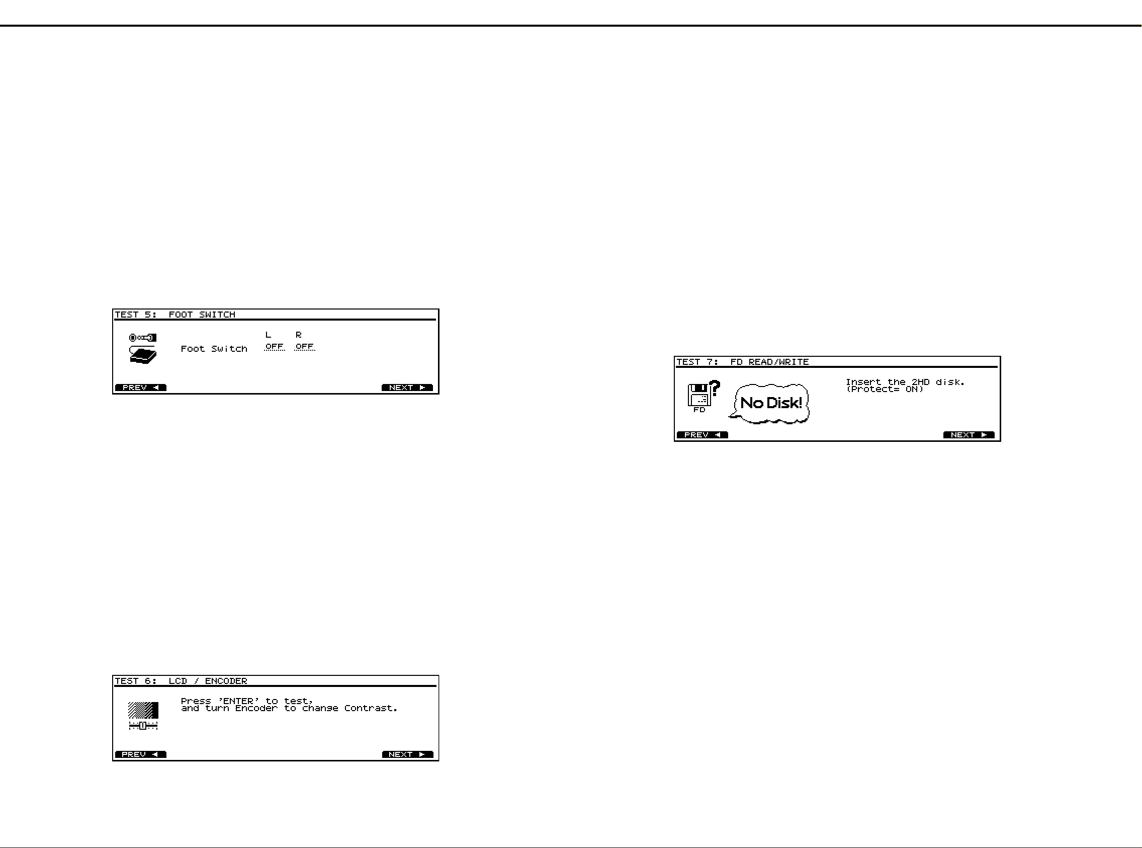
TEST 1: VERSION
1. Display shows the following with bleep.
•Checksum of CPU’s internal ROM and program ROM
•The version number and the date of making
* In TEST 2: DEVICE, when its test will be executed with the
ZIP Drive, Here insert the ZIP disk.
2. Check the version and checksum.Press [F6(NEXT)] to
advance to TEST 2: DEVICE.
・ テストモードから抜けて電源を落とす場合は、 必ず
[SHIFT]+[STOP]
shut down safety."
して下さい。
・ テストモード中で使用した製品やフロッピーディスク、
ディスクをお客様の
ZIP
忘れないでください。
◆テストモードの詳細
◆テストモードの詳細
◆テストモードの詳細◆テストモードの詳細
を押して、
の画面を確認した後、電源を落と
"The MC-80 may now be
から外しておくことを
MC-80
TEST 1: VERSION
1.
・
CPUの内ROM
・プログラムのバージョンおよびリリースした日付
※
TEST 2: DEVICE
行う場合、ここで
内容を確認した後、
2.
および
PROGRAM ROM
において
ディスクを挿入してください。
ZIP
[F6(NEXT)]
ドライブを用いたテストを
ZIP
を押します。
のチェックサム
TEST 2: DEVICE
1. The following check runs automatically.
•CPU’s internal ROM, program ROM and DRAM
•Internal ZIP Drive or hard disk
•SCSI
•VE-GSPro
2. If all devices are working correctly, "OK" appears on
display and TEST 3: MIDI runs automatically.
* If "ERR!" appears on display, Check the following.
CPU’s internal ROM or program ROM or DRAM is
defective.
Check IC3,IC5,IC2 on the MAIN BOARD.
TEST 2: DEVICE
以下のチェックを行います。
1.
・
CPUの内ROM,PROGRAM RO M,D-RAM
・内蔵
・
SCSI
・
VE-GSPro
全てのデバイスが正常に動作している場合は、
2.
示され、自動的に
※ "ERR!" が表示された場合は、以下をチェックしてくださ
い。
ドライブまたはハードディスク
ZIP
TEST 3: MIDI
の内
CPU
MAIN BOARDのIC3,IC5,IC2
ROM,PROGRAM ROM,D-RAM
へ進みます。
をチェックしてください。
"OK"
が不良です。
が表
Install ZIP-INT-1A or HDP-88 in the MC-80. ZIP-INT-1A
Insert a formatted ZIP disk into ZIP-INT-1A. ZIP-INT-1A
い。
してください。
または
HDP-88をMC-80
にフォーマット済みの
に内蔵してくださ
ディスクを挿入
ZIP
11
Page 12
Feb,1999MC-80
1. "Press ’ENTER’ to test" appears on display.
2. Press [ENTER],then check that all dots of display are
turned off.
3. Press [ENTER] again,then check that all dots of display are
turned on.
1. "Press ’ENTER’ to test"
が表示されます。
2. [ENTER]
を押して、ディスプレイ表示が全消灯されている
か確認します。
3.
再び
[ENTER]
を押して、ディスプレイ表示が全点灯され
ているか確認します。
4. Rotate [VALUE] toward the left or right,then check that the
contrast of display changes bright or dark, and that LEDs
light up from [PATTERN] to [MINUS ONE].
5. After checking,press [ENTER] and [F6(NEXT)] to advance
to TEST 7: FDD READ/WRITE.
Here,the contrast of display will return to its normal value.
* If dots of display are lacking, check the following.
• LCD UNIT
• fuji-card connecting MAIN BOARD and LCD UNIT
• IC7 on the MAIN BOARD
* If the contrast of display does NOT change, check the
following.
• ENCODER
• IC13 and circumference chips on the MAIN BOARD
• fuji-card connecting MAIN BOARD and PANEL BOARD
TEST 7: FDD READ/WRITE
4. [VALUE]
を左右に廻して、ディスプレイのコントラストが
変化するか、また
[PATTERN]
から
[MINUS ONE]
まで
LED
が点灯するかを確認します。
5.
確認が終わったら、
[ENTER]
および
[F6(NEXT)]
を押しま
す。
ここで、ディスプレイのコントラストは通常に戻ります。
※ ディスプレイ表示に欠けがある場合、以下をチェックして
ください。
・
LCD UNIT
・
MAIN BOARDとLCD UNIT
を結ぶフジカード
・
MAIN BOARDのIC7
※ ディスプレイのコントラストが変わらない場合、以下を
チェックしてください。
・ エンコーダー
・ MAINBOARD の
IC13
および周辺の回路
・ MAINBOARD と
PANEL BOARD
を結ぶフジカード
TEST 7: FDD READ/WRITE
1. "Insert the 2HD disk.(Protect= ON)" appears on display.
Then insert the 2HD floppy disk to protect on.
2. "Media 2HD/Protect ON" and "Remove the disk." appears
on display.
Remove the disk.
3. "Insert the 2HD disk.(Protect= OFF)" appears on display.
Then insert the 2HD floppy disk to protect off.
4. "Media 2HD/Protect OFF" and "Remove the disk." appears
on display.
Remove the disk.
5. "Insert the 2DD disk.(Protect= OFF)" appears on display.
Then insert the 2HD floppy disk to protect off.
6. "Media 2DD/Protect OFF" and "Remove the disk." appears
on display.
Remove the disk.
7. If steps from 1 to 6 are working correctly, "OK" appears on
display and TEST 8: SOUND runs automatically.
* If steps from 1 to 6 are NOT working correctly, check the
following.
• floppy disk drive unit
• 2 wiring connecting floppy disk drive unit and JACK
BOARD
• IC114 and circumference chips on the JACK BOARD
• fuji-card connecting MAIN BOARD and JACK BOARD
1. "Insert the 2HD disk.(Protect= ON)"
が表示されたら、ライ
トプロテクトをONにした
2HD
のフロッピーディスクを
挿入します。
2. "Media 2HD/Protect ON""Remove the disk."
が表示されま
す。
ディスクを抜きます。
3. "Insert the 2HD disk.(Protect= OFF)"
が表示されます。
ライトプロテクトを
OFF
にした
2HD
のフロッピーディス
クを挿入します。
4. "Media 2HD/Protect OFF""Remove the disk."
が表示されま
す。
ディスクを抜きます。
5. "Insert the 2DD disk.(Protect= OFF)"
が表示されます。
ライトプロテクトを
OFF
にした
2DD
のフロッピーディス
クを挿入します。
6. "Media 2DD/Protect OFF""Remove the disk."
が表示されま
す。
ディスクを抜きます。
7.
手順1から手順6まで正常に動作したら、
"OK"
が表示さ
れ、自動的に
TEST 8: SOUND
へ進みます。
※手順1から手順6まで自動的に進まない場合、以下を
チェックしてください。
・ フロッピーディスクドライブユニット
・ フロッピーディスクドライブと
JACK BOARD
を結ぶワイ
ヤリング2本
・ JACKBOARD の
IC114
および周辺回路
・ MAINBOARD と
JACK BOARD
を結ぶフジカード
1. Check that all LEDs light on.
2. Press the switches on the panel one by one.
The corresponding switch will change into a dot on display
and/or LED will be turned off.
* About [END] key and [BEAT] LED
a. At first, LED lights up orange.
b. Pre ss [END] once, then LED lights up red.
c. Press it again, then LED lights up green.
d. Pre ss it once more, then LED is turned off.
3. If all switches are pressed, "OK" appears on display and
TEST5 : FOOT SWITCH runs automatically.
* If the corresponding switch is NOT change into a dot on
display as each switch is pressed and/or LED is NOT turned
off, check the following.
• the corresponding switch and LED on the PANEL BOARD
• transistors and ICs on the PANEL BOARD
• IC4,IC12,Q1~Q15 on the MAIN BOARD
• fuji-card connecting MAIN BOARD and PANEL BOARD
TEST5 : FOOT SWITCH
が全点灯しているか確認します。
1. LED
パネル上のボタンを1つずつ押してください。
2.
対応する
す。
※ [END] ボタンと
初めはオレンジ色に点灯しています。
a.
b. [END]
再び押すと、緑に変わります。
c.
もう一度押すと、消灯します。
d.
全てのボタンが押されたら、
3.
TEST 5: FOOT SWITCH
※ ボタンを押しても
が消灯しない場合、以下をチェックしてください。
・ PANELBOARDの対応するスイッチ、
・ PANELBOARD上のトランジスタ、
・ MAINBOARD 上の
・ MAINBOARD と
のボタン表示が点になり、
LCD
[BEAT] LED
を押すと、赤に変わります。
LCD
IC4,IC12,Q1〜Q5
PANEL BOARD
について
が表示され、自動的に
"OK"
へ進みます。
のボタン表示が点にならない、
IC
を結ぶフジカード
LED
TEST5 : FOOT SWITCH
LED
が消灯しま
LED
1. Check that "OFF" appears on both channels of foot switch
on display.
2. Connect the stereo plug of PCS-31 cable to FOOT SW
jack, and the other ends to two FS5U.
3. When holding on foot switch connecting to left
channels,"ON" appears on left channels on display.
4. When holding off foot switch connecting to left
channels,"OFF" appears on left channels on display.
5. When holding on foot switch connecting to right
channels,"ON" appears on right channels on display.
6. When holding off foot switch connecting to right
channels,"ON" appears on right channels on display.
7. If steps from 3 to 6 are working correctly, "OK" appears on
display and TEST6 : LCD / ENCODER runs automatically.
* If "ON" or "OFF" does NOT appears on display same as
holding on or off foot switch, check the following.
• circumference chips for foot switch on the JACK BOARD
• fuji-card connecting MAIN BOARD and JACK BOARD
TEST6 : LCD / ENCODER TEST6 : LCD / ENCODER
12
フットスイッチの表示が
1.
確認します。
2. PCS-31
3. L
4. L
5. R
6. R
7.
※ フットスイッチを踏んでも
も
・ JACKBOARDのフットスイッチ回路周辺
・ MAINBOARD と
ケーブルのステレオプラグ側を
ジャックに接続し、他方を
SW
側につながれたフットスイッチを踏んだ時にL側の
表示が
側につながれたフットスイッチを離した時にL側の
表示が
側につながれたフットスイッチを踏んだ時にR側の
表示が
側につながれたフットスイッチを離した時にR側の
表示が
手順3から手順6まで正常に動作したら、
れ、自動的に
"OFF"
になります。
"ON"
になります。
"OFF"
になります。
"ON"
になります。
"OFF"
TEST 6 : LCD / ENCODER
にならない場合、以下をチェックしてください。
JACK BOARD
ともに
L,R
"ON"
"OFF"
MC-80のFOOT
に接続します。
FS-5U
にならない、または離して
を結ぶフジカード
になっているか
"OK"
へ進みます。
が表示さ
Page 13
Feb,1999 MC-80
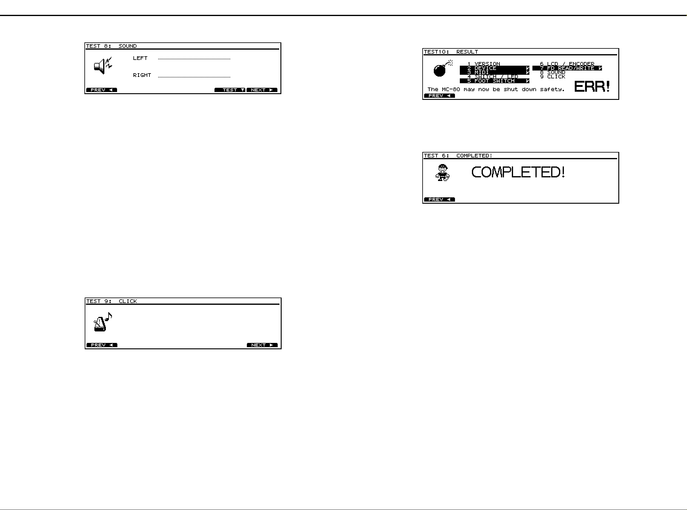
TEST10: RESULT TEST10: RESULT
1. When "ERR!" appears on display, the unpassed test items
that highlighted will appear on display and the
corresponding [TRACK] LEDs will blink.
2. The MC-80 power can be turned off in this state.
Press the corresponding blinking LED when going back to
the unpassed test item.
1. "ERR!"
が、ディスプレイに表示されている場合、
"OK"
に
ならなかったテスト項目が反転表示され、対応する
TRACK
ボタンの
LED
が点滅します。
2.
この状態で電源を落とせます。
もし、
"OK"
にならなかったテスト項目に戻る場合は、対
応する点滅中の
LED
を押してください。
1. When "COMPLETED!" appears on display, it means all the
test items have been completed.
2. The MC-80 power can be turned off in this state.
1. "COMPLETED!"
が、ディスプレイに表示されている場合、
全てのテスト項目を正常に終えたことを示します。
2.
この状態で電源を落とせます。
TEST 8: SOUND TEST 8: SOUND
1. Connect the headphones into PHONES jack.
Connect the monitor speaker into OUTPUT jack.
(It has no problem to check the signal with an
oscilloscope.)
Raise [EXPANSION VOLUME] suitably.
2. Check that no sound is heard from the headphones and
the monitor speaker.
3. Press [F5(TEST)],then check that a sine wave sound is
heard from left channels.
4. Press [F5(TEST)] again,then check that a sine wave sound
is heard from right channels.
5. Press [F5(TEST)] once more,then check that a sine wave
sound is heard from both channels.
6. Press [F5(TEST)] once more,then check that no sound is
heard from both channels.
7. After checking,disconnect the headphones and the monitor
speaker.
Press [F6(NEXT)] to advance to TEST 9: CLICK.
* If the sound is NOT heard correctly, check the following.
• VE-GSPro
• IC101,IC102,IC103,IC130 and circumference chips on the
JACK BOARD
• VR BOARD and wiring connecting it
• fuji-card connecting MAIN BOARD and JACK BOARD
ヘッドホンを
1.
モニタースピーカーを
出力波形をオシロスコープで確認しても構いません。)
(
[EXPANSION VOLUME]
ヘッドホンとモニタースピーカーからは音が出力されてい
2.
ないか確認します。
3. [F5(TEST)]
ます。
再び
4.
[F5(TEST)]
確認します。
再び
5.
[F5(TEST)]
確認します。
再び
6.
[F5(TEST)]
か確認します。
確認が終わったら、ヘッドホンとモニタースピーカーの
7.
ケーブルを外し、
※ 発音に異常がある場合、以下をチェックしてください。
・
VE-GSPro
・
JACK BOARDのIC101,IC102,IC103,IC130
路
・
VR BOARD
・
MAIN BOARDとJACK BOARD
PHONES
を押し、左側からサイン波の音がするか確認し
およびワイヤリング
ジャックに接続します。
OUTPUT
を押し、右側からサイン波の音がするか
を押し、両側からサイン波の音がするか
を押し、両側とも音が出力されていない
[F6(NEXT)]
ジャックに接続します。
を適当に上げます。
を押します。
および周辺回
を結ぶフジカード
TEST 9: CLICK TEST 9: CLICK
1. A metronomic click will sound from internal speaker.
2. Check the volume change by turning [CLICK LEVEL] on
the rear panel.
3. Connect the headphones into PHONES jack, then check
that the sound is only heard from the headphones which
overrides internal speaker.
4. After checking,disconnect the headphones.
Press [F6(NEXT)] to advance to TEST 10: RESULT.
* If no sound is heard, check the following.
• SP101,JK102,VR101 and circumference chips on the
JACK BOARD
• fuji-card connecting MAIN BOARD and JACK BOARD
本体からクリック音が鳴り始めます。
1.
リアパネルにある
2.
がレベル変化するか確認します。
ヘッドホンを
3.
クリック音が消え、ヘッドホンからのみクリック音がする
か確認します。
確認が終わったら、ヘッドホンを外し、
4.
します。
※ 発音しない場合、以下をチェックしてください。
・
JACK BOARDのSP101,JK102,VR101
・
MAIN BOARDとJACK BOARD
[CLICK LEVEL]
PHONES
を回して、クリック音
ジャックに接続すると、本体から
[F6(NEXT)]
および周辺回路
を結ぶフジカード
を押
13
Page 14

Feb,1999MC-80
11112
AAAA
23
22
BLOCK DIAGRAM /ブロック図
BBBB
CCCC
DDDD
EEEE
FFFF
GGGG
HHHH
34
33
JACK BOARD
FOOT
SW
JK109
MIDI
IN 1
JK108
MIDI
IN 2
45
44
JK101
56
55
/ブロック図
/ブロック図/ブロック図
67
66
78
77
89
88
910
99
IC3 IC2
CPU
SH7021
10 11
1010
BA
IC4
11 12
1111
MAIN BOARD
ADDRESS BUS, DATA BUS, CONTROL BUS
12 13
1212
DRAM
16Mbit
13 14
1313
14 15
1414
15 16
1515
IC5
FLASH ROM
8Mbit
IC7IC8
16 17
1616
17 18
1717
18 19
1818
19 20
1919
uPD72070
IC114
FDC
20 21
2020
21 22
2121
22 23
2222
23 24
2323
Option
24 25
2424
25 26
2525
26 27
2626
FDD UNIT
ZIP Drive
ZIP-INT-1A
27 28
2727
28
2828
IIII
JJJJ
KKKK
LLLL
MMMM
NNNN
OOOO
PPPP
QQQQ
JK107
MIDI
THRU
JK105
MIDI
OUT 1
JK103
MIDI
OUT 2
Option
or
mounted on
MC-80EX
MIDI
PATCH
GATE ARRAY
M60205-0601FP
ENCODER SW & LED
PANEL/SWITCH BOARD
IC101
DAC
uPD6379
SRAM
256Kbit
LPF
LCDC
SED1335
RCM6027T-1A
LCD UNIT
IC103
OpAMP
M5218
IC130
OpAMP
M5218
BUFFERS
BUFFERS
+
+
IC102
OpAMP
M5216
IDE BOARDIDE BOARD
JK104
JK106
JK102
Option
Option
OUTPUT L
(MONO)
OUTPUT R
PHONES
Hard Disk
Drive Unit
HDP88
SCSI
BOARD
VS4S-1
14
RRRR
SSSS
TTTT
UUUU
VOICE
EXPANSION
BOARD
VE-GSPro
VR601
VR BOARD
SP101 LPF
BUZZER
PKM22EP-2001
VR101
A
B
CLICK LEVEL
Page 15

Feb,1999 MC-80
11112
AAAA
BBBB
23
22
CIRCUIT BOARD /基板図
MAIN BOARD ASSY (71122001)
34
33
45
44
/基板図
/基板図/基板図
56
55
CCCC
DDDD
EEEE
FFFF
GGGG
HHHH
67
66
78
77
89
88
910
99
10 11
1010
11 12
1111
12 13
1212
13 14
1313
14 15
1414
15 16
1515
16 17
1616
17 18
1717
18 19
1818
19 20
1919
20 21
2020
21 22
2121
22 23
2222
23 24
2323
24 25
2424
25 26
2525
26 27
2626
27 28
2727
28
2828
IIII
JJJJ
KKKK
LLLL
MMMM
NNNN
OOOO
PPPP
QQQQ
View from component side. View from foil side.
RRRR
SSSS
TTTT
UUUU
15
Page 16

Feb,1999MC-80
11112
23
22
34
33
45
44
56
55
AAAA
PANEL BOARD ASSY (71122012)
BBBB
CCCC
DDDD
EEEE
FFFF
GGGG
HHHH
67
66
78
77
89
88
910
99
10 11
1010
11 12
1111
12 13
1212
13 14
1313
14 15
1414
15 16
1515
16 17
1616
17 18
1717
18 19
1818
19 20
1919
20 21
2020
21 22
2121
22 23
2222
23 24
2323
24 25
2424
25 26
2525
26 27
2626
27 28
2727
28
2828
IIII
JJJJ
KKKK
LLLL
MMMM
NNNN
OOOO
PPPP
QQQQ
16
RRRR
SSSS
TTTT
UUUU
Page 17
Feb,1999 MC-80
11112
23
22
34
33
45
44
56
55
AAAA
JACK BOARD ASSY (71122045)
BBBB
CCCC
DDDD
EEEE
FFFF
GGGG
HHHH
67
66
78
77
89
88
910
99
10 11
1010
11 12
1111
12 13
1212
13 14
1313
14 15
1414
15 16
1515
16 17
1616
17 18
1717
18 19
1818
19 20
1919
20 21
2020
21 22
2121
22 23
2222
23 24
2323
24 25
2424
25 26
2525
26 27
2626
27 28
2727
28
2828
IIII
JJJJ
KKKK
LLLL
MMMM
NNNN
OOOO
PPPP
QQQQ
RRRR
SSSS
TTTT
UUUU
View from component side.
17
Page 18

Feb,1999MC-80
11112
23
22
34
33
45
44
56
55
AAAA
JACK BOARD ASSY (71122045)
BBBB
CCCC
DDDD
EEEE
FFFF
GGGG
HHHH
67
66
78
77
89
88
910
99
10 11
1010
11 12
1111
12 13
1212
13 14
1313
14 15
1414
15 16
1515
16 17
1616
17 18
1717
18 19
1818
19 20
1919
20 21
2020
21 22
2121
22 23
2222
23 24
2323
24 25
2424
25 26
2525
26 27
2626
27 28
2727
28
2828
IIII
JJJJ
KKKK
LLLL
MMMM
NNNN
OOOO
PPPP
QQQQ
18
RRRR
SSSS
TTTT
UUUU
View from foil side.
Page 19

Feb,1999 MC-80
11112
AAAA
BBBB
23
22
CIRCUIT DIAGRAM /回路図
34
33
45
44
56
55
/回路図
/回路図/回路図
MAIN BOARD ASSY (71122001)
CCCC
DDDD
+
5D
B
A
CLR
CK
1
2
4Y
3Y
2Y
1Y
ST
DD D
C36
5D
0.1
IC13C
M5218AFP
C37
0.1
5D
IC1D
TC7W14F
D
D
+
5D
14
VCC
QH
QG
QF
QE
QD
QC
GND
QB
QA
IC17
7
HD74HC164FPEL
D
+
5D
5 3
IC16
TC7S32F
D
D
12
9
SCSIDACK
7
FDCDACK
4
DREQ1
1
DMACTR
15
+
5D
8 4
IC10C
TC7W02F
D
C39
0.1
BLM11A601S
L1
L2
L3
L4
L5
L6
L7
L8
L9
L10
L11
L12
L13
L14
L15
C45
0.1
13
12
11
10
6
5
4
3
C43
0.1
4
D
D
D
D
EEEE
FFFF
GGGG
HHHH
IIII
JJJJ
KKKK
LLLL
MMMM
NNNN
OOOO
PPPP
QQQQ
RRRR
SSSS
TTTT
UUUU
25
25
24
24
23
23
22
22
21
21
20
20
19
19
18
18
17
17
16
16
15
15
14
1 7
IC1A
TC7W14F
14
13
13
12
12
11
11
10
10
9
9
8
8
7
7
6
6
5
5
4
4
3
3
2
2
1
1
CN1
IL-FPC-25ST-N
20M
PANEL
BOARD
XIDEWAIT
XCS6
WAIT CONTROL
+
5D
14
4A
11
3A
6
-
5
+
IC13B
M5218AFP
D
5
2
13
10
6
3
+
5D
8 4
2A
1A
4B
3B
2B
1B
C31
0.1
IC9C
TC7W02F
7
DACK1
FDCDREQ
SCSIDREQ
DMA CONTROL
(FDC or SCSI)
C30
0.1
SW2
SW1
+
5D
2
1
9
8
XQF
C27
+
5D
0.1
16
VCC
GND
SEL
IC6
8
TC74HC157AF
D
+
8 4
-
+
-15
+
8 4
67
66
5D
R2
R1
100k
100k
ENCB
ENCA
ENCB
ENCA
XSSEN
SS2
SS1
SS0
LLCK
PD0
PD1
PD2
PD3
PD4
PD5
PD6
PD7
LEDS0
LEDS1
LEDS2
LEDS3
LEDS4
D
D
LEDS4
LEDS3
LEDS2
LEDS1
LEDS0
LCDPWM
1
2
+
5D
R17
1k
1 2
+
5D
32
32
32
32
32
C44
+
5D
0.1
5 3
IC15
TC7S08F
D
RA15
10k
Q1
DTB123TK
1
Q2
DTB123TK
1
Q3
DTB123TK
1
Q4
DTB123TK
1
Q5
DTB123TK
1
+
5D
C42
CV@B
10/16
4
3
4
5
6
7
8
910
R14
12k
R18
22k
PD[0..7]
XWAIT
PD0
PD1
PD2
PD3
PD4
PD5
PD6
PD7
78
77
+5D+
R5 100k IC1B
R7 100k R8 1k
SS[0..2]
89
88
TC7W14F
3 5
6 2
IC1C
C2
C1
0.01
D
D
IC12
TC74HC138AF
2
-
3
+
IC13A
R19
M5218AFP
10k
TC7W14F
0.01
7
Y7
9
Y6
10
Y5
11
Y4
12
Y3
13
Y2
14
Y1
15
Y0
C47
47P
R15
22k
1
NTH5G1M33B103J
LS[0..3]
VCC
GND
910
99
(SHIFT)
SW1
(TAP)
SW2
C3
0.01
C15
C16
0.1
0.1
+
5D
C14
0.1
D
6
QIN1
XDWRL
XWAIT
XDMAWR
TAP
VESENS
FOOT1_R
FOOT1_L
DMACTR
TC
FDCPWM
LCDPWM
SS2
SS1
SS0
LS3
LS2
LS1
LS0
XSSEN
LLCK
PD7
PD6
PD5
PD4
PD3
PD2
PD1
PD0
+
16
8
MIDI IN
4
WRHO
5
WRLO
25
WAIT IN
66
PORT7
65
PORT6
64
PORT5
63
PORT4
62
PORT3
61
PORT2
60
PORT1
59
PORT0
3
PWM 2
67
PWM 1
69
ENC B
68
ENC A
74
SS3
73
SS2
72
SS1
71
SS0
78
LS3
77
LS2
76
LS1
75
LS0
70
SSEN
81
LLCK
89
PD7
88
PD6
87
PD5
86
PD4
85
PD3
84
PD2
83
PD1
82
PD0
90
RS/CD
91
R/W
92
LE/RD
100
LCD 7
99
LCD 6
98
LCD 5
97
LCD 4
96
LCD 3
95
LCD 2
94
LCD 1
93
LCD 0
C32
5D
0.1
D
3
LS2
2
LS1
1
LS0
5
4
LS3
6
XRESET
D
LCDCV
2 3
D1
DSD010-TB
DDD D
R20
1k
D
R16
10k
G2B
G2A
C
B
A
G1
10 11
1010
C17
0.1
EXCITON
VSS1VSS28VSS33VSS40VSS53VSS
R6 1k
C4
0.01
D
VDD2VDD29VDD52VDD
D
OUT2
OUT1
THRU
IN2
IN1
11 12
1111
+5D+5D+
5D
R3
100kR4100k
TAP
+
5D
79
XRD
XWRH
XWRL
XDREQ
XDACK
WAIT OUT
CS6
CS4
CS2
XIREQ
ECS11
ECS10
ECS9
ECS8
ECS7
ECS6
ECS5
ECS4
ECS3
ECS2
ECS1
ECS0
EXTINT2
EXTINT1
EXTINT0
CLK IN
CLK OUT
RESET
80
IC4
M60205-0601FP
R21
100
R22
100
R23
100
MIDI PATCHLCD CONTRAST
A21
A20
A19
A5
A4
A3
A2
A1
A0
D7
D6
D5
D4
D3
D2
D1
D0
IC9A
TC7W02F
7
3
IC9B
TC7W02F
23
22
21
20
19
18
17
16
15
14
13
12
11
10
9
8
7
34
35
36
31
32
37
41
39
38
24
55
54
51
50
49
48
47
46
45
44
43
42
58
57
56
27
30
26
12 13
1212
CA21
CA20
CA19
CA5
CA4
CA3
CA2
CA1
CA0
CD7
CD6
CD5
CD4
CD3
CD2
CD1
CD0
XRD
XWRH
XWRL
XCS4
XCS2
XGAINT
XIDECS
XLCDCS
XFDCCS
XSCSICS
XPROMCS
TAP
XSCSIINT
XIDEINT
XRESET
R10 100
+
5D
*1 *1
R29
10k
1
2
OUT2_OFF
5
6
OUT1_OFF
THRU_CTR
VEIN2_CTR
VEIN1_CTR
+
5D
VEOUT
IN2
IN1
IN_CTR2
D
IN_CTR1
13 14
1313
R30
10k
4
1
2
13
12
9
10
11
6
IC11
D
HD74HC4053FPEL
13
12
11
10
3
4
5
6
2
14
15
1
IC14
D
TC74HC153AF
ZCOM
1Y
0Y
1X
0X
C
B
A
INH
2C3
2C2
2C1
2C0
1C3
1C2
1C1
1C0
B
A
2G
1G
14 15
1414
XCS6
XRAS
XCASL
XCASH
R26 100
R27 100
R28 100
C25 15P
C26 15P
D
1Z
0Z
YCOM
XCOM
VCC
GND
VEE
9
2Y
7
1Y
16
VCC
8
GND
QOUT2
IN2
QOUT1
QIN1
PB7
FLASH
CLICK_NP
CLICK_IP
OUT1_OFF
OUT2_OFF
VEIN1_OFF
VEIN2_OFF
IN_CTR1
IN_CTR2
VEIN1_CTR
VEIN2_CTR
THRU_CTR
X1
MA-406@
20.000MHz
XRESET
C28
0.01
3
5
15
14
+
5D
16
C35
0.1
8
7
+
5D
15 16
1515
C5
0.1
C6
0.1
C7
0.1
C8
0.1
C9
0.1
C10
0.1
+
5D
79
78
77
D
96
95
94
93
91
90
89
87
86
85
84
83
64
62
61
60
58
54
53
52
51
49
48
47
46
71
72
14
76
D
VEIN2_OFF
VEIN1_OFF
D
IN2
QIN1
C41
0.1
D
16 17
1616
1 2
RA1
10k
345678910
CD3
CD5
CD0
MD2
MD1
MD0
TXD1/PB11/TP11
RXD1/PB10/TP10
TXD0/PB9/TP9
RXD0/PB8/TP8
PB7/TP7/*
PB6/TP6/*
PB5/TP5/*
PB4/TP4/*
PB3/TP3/*
PB2/TP2/*
PB1/TP1/*
PB0/TP0/*
PA11/DPH/*
PA10/DPL/*
PA9/AH/IREQOUT
PA8/BREQ
PA7/BACK
WAIT/CS7/PA3
CS6/TIOCB0/PA2
RAS/CS5/PA1
CS4/TIOCA0/PA0
CASL/CS3
CS2
CASH/CS1
CS0
EXTAL
XTAL
RES
CD7
CD4
CD1
CD2
CD6
C13
D
CV@B
100/6.3
VCC13VCC38VCC63VCC73VCC80VCC
SH7021
VSS4VSS15VSS24VSS32VSS41VSS50VSS59VSS70VSS81VSS82VSS
IC10A
TC7W02F
1
2
5
6
IC10B
TC7W02F
RA2
10k
CD8
CD10
CD9
CD11
+
5D
88
A0(HBS)
PA5/WRH(LBS)
PA4/WRL(WR)
PA6/RD
WDTOVF
*/PB15/IREQ7
*/PB14/IREQ6
*/PB13/IREQ5
*/PB12/IREQ4
*/PA15/IREQ3
*/PA14/IREQ2
*/PA13/IREQ1
*/PA12/IREQ0
92
D
7
R24
100
3
R25
100
17 18
1717
+5D+
1 2
345678910
CD14
CD13
CD12
CD15
A21
A20
A19
A18
A17
A16
A15
A14
A13
A12
A11
A10
A9
A8
A7
A6
A5
A4
A3
A2
A1
AD15
AD14
AD13
AD12
AD11
AD10
AD9
AD8
AD7
AD6
AD5
AD4
AD3
AD2
AD1
AD0
NMI
CK
IC3
HD6437021
QOUT2
QOUT1
VEOUT
VEIN2
VEIN1
45
44
43
42
40
39
37
36
35
34
33
31
30
29
28
27
26
25
23
22
21
20
19
18
17
16
14
12
11
10
9
8
7
6
5
3
2
1
56
55
57
75
100
99
98
97
68
67
66
65
74
69
EXBV8V
RA8 100
RA10 100
RA12 100
RA13 100
RA14 100
1 8
2 7
3 6
4 5
1 8
2 7
3 6
4 5
1 8
2 7
3 6
4 5
1 8
2 7
3 6
4 5
1 8
2 7
3 6
4 5
R12 100
18 19
1818
5D
1 2
RA3
10k
345678910
CA2
CA4
CA1
CA3
CA6
CA0
CA5
CA7
CA21
CA20
CA19
CA18
CA17
CA16
CA15
CA14
CA13
CA12
CA11
CA10
CA9
CA8
CA7
CA6
CA5
CA4
CA3
CA2
CA1
CA0
CD15
CD14
CD13
CD12
CD11
CD10
CD9
CD8
CD7
CD6
CD5
CD4
CD3
CD2
CD1
CD0
XWRH
XWRL
XRD
+
5D
R9
10k
XGAINT
XINDEX
XFDCINT
DREQ1
DACK1
DREQ0
DACK0
20M
10M
1
2
3
4
5
6
LCD
7
8
9
10
11
12
13
14
CN4
IL-FPC-14ST-N
19 20
1919
1 2
RA4
10k
345678910
CA11
CA8
CA9
CA13
CA12
CA10
R13
10k
RA16 100
RA17 100
4 5
1
3 6
2
2 7
3
1 8
4
5
4 5
3 6
6
2 7
7
1 8
8
+
5D
9
C38 0.1
10
11
12
13
C40
14
0.1
-15
D
20 21
2020
RA5
10k
CA16
CA14
CA15
CA17
XRAS
XCASH
XCASL
XDWRL
XRD
XPROMCS
XWRL
XRD
XRESET
FLASH
+
5D
D
LCDCV
D D
CA19
CA18
CA10
CA9
CA8
CA7
CA6
CA5
CA4
CA3
CA2
CA1
CA19
CA18
CA17
CA16
CA15
CA14
CA13
CA12
CA11
CA10
CA9
CA8
CA7
CA6
CA5
CA4
CA3
CA2
CA1
R11
4.7k
10M
CD7
CD6
CD5
CD4
CD3
CD2
CD1
CD0
CA0
XWRL
XLCDCS
XRESET
XD0
XD1
XD2
XD3
LP
XSCL
WF
YD
345678910
CA20
D
21 22
2121
1 2
EXBA10E
CA21
CA[0..21]
CD[0..15]
28
27
26
25
24
23
20
19
18
17
32
16
15
12
11
14
30
31
13
29
5
6
7
8
10
11
12
13
17
18
19
20
22
23
24
25
26
27
28
32
+
5D
2
14
55
54
31
53
56
16
1
D
C29 0.1
D
17
OSC1
18
OSC2
29
D7
28
D6
27
D5
26
D4
25
D3
24
D2
23
D1
22
D0
20
A0
13
RD
14
WR
19
CS
10
RES
15
SEL2
16
SEL1
33
XD0
32
XD1
31
XD2
30
XD3
37
LP
35
XSCL
38
WF
40
YD
34
XECL
41
YSCL
39
YDIS
A9
DQ15
A8
DQ14
A7
DQ13
A6
DQ12
A5
DQ11
A4
DQ10
A3
DQ9
A2
DQ8
A1
DQ7
A0
DQ6
DQ5
NC
DQ4
NC
DQ3
NC
DQ2
NC
DQ1
NC
DQ0
D-RAM
VCC
16M
RAS
VCC
UCAS
VCC
LCAS
W
OE
VSS
VSS
VSS
IC2
TMS418169A-60
A19
DQ15
A18
DQ14
A17
DQ13
A16
DQ12
A15
DQ11
A14
DQ10
A13
DQ9
A12
DQ8
A11
DQ7
A10
DQ6
A9
DQ5
A8
DQ4
A7
DQ3
A6
DQ2
A5
DQ1
A4
DQ0
A3
A2
NC
A1
NC
A0
NC
FLASH
NC
8M
VPP
CE1
CE0
WE
VCC
OE
VCC
BYTE
VCC
RY/BY
WP
VSS
RP
VSS
3/5
VSS
IC5
LH28F800SUT-70
+
5D
21
VDD
VA15
VA14
VA13
VA12
VA11
VA10
LCDC
VWR
VSS
36
IC7
SED1335F0B
22 23
2222
41
CD15
40
CD14
39
CD13
38
CD12
36
CD11
35
CD10
34
CD9
33
CD8
10
CD7
9
CD6
8
CD5
7
CD4
5
CD3
4
CD2
3
CD1
2
CD0
+
5D
21
6
1
42
37
22
D
C20
C18
C19
0.1
0.1
0.1
52
CD15
50
CD14
47
CD13
45
CD12
41
CD11
39
CD10
36
CD9
34
CD8
51
CD7
49
CD6
46
CD5
44
CD4
40
CD3
38
CD2
35
CD1
33
CD0
3
4
CA20
29
30
15
+
9
37
43
C22
21
0.1
42
48
50
51
52
53
54
55
56
VA9
57
VA8
58
VA7
59
VA6
1
VA5
2
VA4
3
VA3
4
VA2
5
VA1
6
VA0
42
VD7
43
VD6
44
VD5
45
VD4
46
VD3
47
VD2
48
VD1
49
VD0
7
9
VRD
8
VCE
11
NC
12
NC
60
NC
23 24
2323
C23
5D
0.1
D
<NOTICE>
*1 On Products with S/N ZL50100-ZL50199, R29(10k) and R30(10k) is not mounted.
C21
CV@B
100/6.3
C24
0.1
24 25
2424
C46
0.1
VD7
VD6
VD5
VD4
VD3
VD2
VD1
VD0
C11
CV@B
100/6.3
+
5D
25 26
2525
+
5D
C12
0.1
D
XIDEINT
DACK0
XIDEWAIT
DREQ0
XIDECS
CA4
1 8
CD15
2 7
CD14
3 6
CD13
4 5
CD12
1 8
CD11
2 7
CD10
3 6
CD9
4 5
CD8
IN1
IN2
THRU
OUT1
OUT2
FOOT1_L
FOOT1_R
CLICK_IP
CLICK_NP
FDCPWM
PB7
FDCDACK
XFDCCS
XFDCINT
FDCDREQ
TC
XSCSICS
XRESET
SCSIDACK
SCSIDREQ
XSCSIINT
XRD
XWRL
CA3
CA2
CA1
CA0
1 8
CD7
2 7
CD6
3 6
CD5
4 5
CD4
1 8
CD3
2 7
CD2
3 6
CD1
4 5
CD0
VEIN2
VESENS
VEIN1
VEOUT
XDMAWR
XINDEX
RA9 100
RA11 100
1
D
A14
26
A13
2
A12
23
A11
21
A10
24
A9
25
A8
3
A7
4
A6
5
A5
6
A4
S-RAM
7
A3
8
256K
A2
9
A1
10
A0
20
CE
27
R/W
22
OE
IC8
TC55257DFL-70L
RA6 100
RA7 100
VDD
GND
I/O8
I/O7
I/O6
I/O5
I/O4
I/O3
I/O2
I/O1
26 27
2626
1
1
2
2
3
3
4
4
5
5
6
D
6
7
-15
7
8
8
9
9
10
10
11
11
12
12
13
13
14
14
15
15
16
16
17
17
18
18
19
19
20
20
21
21
22
22
23
23
24
24
25
25
26
26
CN2
IL-FPC-26ST-N
1
1
2
2
3
3
4
4
5
5
6
6
7
7
8
8
9
9
10
10
11
11
12
12
13
13
14
14
15
15
16
16
17
17
18
18
19
19
20
20
21
21
22
22
23
23
24
24
25
25
26
26
27
27
28
28
29
29
30
30
31
31
32
32
33
33
34
34
35
35
CN3
52045-3545
VD[0..7]
19
VD7
18
VD6
17
VD5
16
VD4
15
VD3
13
VD2
12
VD1
11
VD0
C33
+
5D
0.1
C34
28
CV@B
100/6.3
14
D
27 28
2727
JACK
BOARD
JACK
BOARD
28
2828
19
Page 20

Feb,1999MC-80
11112
23
22
34
33
45
44
56
55
AAAA
JACK BOARD ASSY 1/2 (71122045)
BBBB
+
5D
CCCC
DDDD
EEEE
FFFF
GGGG
Voice
Expansion
Board
(VE-GSpro)
AN0
AN1
AN2
AN3
AN4
AN5
SENSE
XRST
DGND
DGND
DACA
DACB
DACC
SDATA
SCK
CLK
RXD
TXD
VCC
VCC
CN101
52411-0202
R101
12k
1
2
3
4
5
6
7
8
9
10
11
12
13
14
15
16
17
18
19
20
C124
0.1
R102
47k
D
+
D D
5D
C125
100/6.3
RA101
100
4 5
3 6
2 7
1 8
4 5
3 6
2 7
1 8
RA103
100
IC132
TC7S04F
R119
10k
D
HHHH
MIDI
OUT2
MIDI
OUT1
MIDI
THRU
MIDI
IN2
MIDI
IN1
JK103
M0094
JK105
M0094
JK107
M0094
JK108
M0094
JK109
M0094
1
1
4
4
2
2
5
5
3
3
1
1
4
4
2
2
5
5
3
3
1
1
4
4
2
2
5
5
3
3
1
1
4
4
2
2
5
5
3
3
1
1
4
4
2
2
5
5
3
3
C233
C234
L107
L109
L110
L111
L113
L114
L115
0.1
0.1
BLM21A601S
BLM21A601S
BLM21A601S
BLM21A601S
BLM21A601S
BLM21A601S
BLM21A601S
L116
L117
A
A
L118
L119
BLM21A601S
L105
BLM21A601S
L106
IIII
JJJJ
KKKK
LLLL
MMMM
NNNN
OOOO
PPPP
QQQQ
RRRR
C166
+
14
0.1
SSSS
TTTT
IC102C
M5216FP
A
A
C173
0.1
8 4
IC103C
+
M5218AFP
-14
UUUU
67
66
+
5D
5 3
VESENS
C142 100P
C143 100P
D
C145 100P
C146 100P
D
C149 100P
C151 100P
D
BLM21A601S
BLM21A601S
BLM21A601S
BLM21A601S
C167
0.1
A
A
C174
0.1
78
77
C229
0.1
D
24
IC131B
TC7W04F
C153 100P
C155 100P
D
C156 100P
C159 100P
D
+
14
8 4
+
-14
VEIN2
XRESET
35
1 7
OUT2_4P
OUT2_5P
OUT1_4P
OUT1_5P
THRU_4P
THRU_5P
RA102
10k
VEIN1
IC131A
TC7W04F
IN2_4P
IN2 5P
IN1_4P
IN1_5P
IC130C
M5218AFP
D
6 2
IC131C
TC7W04F
+
5D
182736
VEOUT
R144 220
R146 220
R152 220
R153 220
R159 220
R161 220
R163
120
R167
100
R168
120
R174
100
C109
0.1
A
A
C119
0.1
89
88
45
UPD6379
1
RXL
2
SD
3
SCK
+
14
8 4
+
-14
910
99
C104
+
5A
100/6.3
C107
0.1
IC101
4
VDD
LOUT
ROUT
GND
REF
7
C122
100/6.3
+
5D
R135
Q107
DTA114EK
32
10k
1
+
5D
7
VCC
C135
0.1
4
GND
D D
IC105
M51954BFP
IC106D
HD74LS05FP
IC106E
HD74LS05FP
IC106A
HD74LS05FP
D104
DSD010-TB
D105
DSD010-TB
VR101B
10KBx2
10
20
A
A
8
5
6
AA
+
5D
6
RST
DLY
NC
NC
NC
NC
98
1110
12
1
23
3
1
23
3
10 11
1010
CLICKRTN
R103
10k
D
5
1
2
3
8
+
+
+
+
6 4
+
6 4
3 4
IC106B
HD74LS05FP
D
5 6
IC106C
HD74LS05FP
D
11 12
1111
C102
0.027
C105
0.027
R111
C110
10k
10/16
R115
100k
A A
R123
C120
10k
10/16
R129
100k
+
5D
C131
0.1
5 3
IC104
TC7S04F
2 4
C136
1
D D D
5D
R148
10k
5D
R154
10k
5D
R157
10k
IC106F
HD74LS05FP
1312
C152
5D
0.1
D
5
IC107
PC410T
D
5D
C154
0.1
D
5
IC108
PC410T
D
C228
0.1
C170
0.1
12 13
1212
R104
100
R106
3.3k
A AA A
R112
10k
C112
470P
R124
10k
C126
470P
AA A
XRESET
C137
R141
0.01
4.7k
OUT2
OUT1
+
5D
R158
10k
THRU
+
5D
R164
4.7k
IN2
+
5D
R171
4.7k
IN1
+
5D
8 4
IC131D
TC7W04F
DD
+
5D
14 7
IC106G
HD74LS05FP
DD
C106
1000P
R113
10k
C113
2700P
R125
10k
C127
2700P
C103
10/16
C164
10/25
C168
10/25
13 14
1313
CLICK
R107
100k
1
C114
Q103
180P
3 2
2SA1037KR
-14
A
1
C128
Q105
180P
3 2
2SA1037KR
-14
C235
0.1
A D
C236
0.1
A D
C237
0.1
DA
C238
0.1
A D
Q113
+
2SC2882Y
14
3 2
R175
1k
1
C165
100/16
C169
100/16
1
R176
1k
23
-14
Q114
2SA1202Y
14 15
1414
3
R118
390
3
R130
390
+
15
-15
+
14
12
+
14
12
C239
A D
C240
C241
A D
C242
A D
C243
C244
A
A
A+5V
15 16
1515
Q101
2SK208Y
C117
10/16
Q104
2SK208Y
C129
10/16
0.1
0.1
DA
0.1
0.1
0.1
DA
0.1
D
XRESET
+
5D
D
D106
DSD010-TB
C148
220/6.3
C227
220/10
C171
0.1
23
16 17
1616
CLICK
C111
2
10/16
3
R116
100k
A
CLICK
C123
6
10/16
5
R131
100k
A
C133
10/16
R138
100k
C141
10/16
R149
100k
+
5D
2 3
D103
DSD010-TB
A
R166
100k
1
Q111
23
2SC2412KR
D+5V
DG
A
IC109
AN78L05M
1
OUT
COM
2
17 18
1717
RETURN_R
SEND_R
SEND_L
RETURN_L
R204
33k
1
+
R114
IC130A
7
IC130B
M5218AFP
R142
10k
A
R133
10k
A
R162
3.3k
1
Q112
+
+
5A
-15
3
IN
1k
R205
33k
R128
C130 47P
R134 47k
R156
100k
23
15
+15V
C172
0.1
-15V
1k
C138
R143 47k
6
5
A
2
3
A
+15V
A+5V
AG
-15V
M5218AFP
+
R155
47k
2SC2412KR
A A A
18 19
1818
R108
5.6k
1
Q102
DTC343TK
23
A
R120
5.6k
1
Q106
DTC343TK
23
A
47P
C132
IC103B
M5218AFP
IC103A
M5218AFP
R160
100k
2SA1037KR
C150
10/16
AG
D+5V
DG
10/25
7
C140
10/25
1
1
Q110
R165
47k
C162
100/6.3
+
+
19 20
1919
C108
47P
R109
2
47k
1
3
+
IC102A
M5216FP
A
C118
47P
R121
6
47k
7
5
+
IC102B
M5216FP
A
R139
56k
A
R150
56k
A
32
MUTE
FOOT1_L
FOOT1_R
-14
+
5D
C160
C161
220/10
D
+
5D
C163
D
1
1
2
2
3
3
4
4
5
5
6
6
7
7
CN106
B7B-XH-A
20 21
2020
R110
22
R117
56k
R126
22
R132
56k
R136
330
1
R140
1k
R145
330
1
R151
1k
0.1
0.1
Switching
Power
Unit
21 22
2121
PHONES_L
C225
1000P
A
PHONES_R
C226
1000P
A
OUT_L
Q108
2SC3326A
23
A
OUT_R
Q109
2SC3326A
23
A
1 2
DA102
DCF010-TL
1
1
2
2
3
3
CN103
B3P-VH
1
1
2
2
3
3
CN105
B3B-PH-K-S
22 23
2222
CLICK_NP
A
CLICK_IP
A
+
5D
3
DA101
DCG010-TL
12
3
D D D
IDE
Power
FDD
Power
1
R147
1
Q115
DTC114EK
OUT_L
OUT_R
R172
1k
R173
1k
C157
C158
0.01
0.01
10
20
SW101B
SDDLB1-B2-D-2
23 24
2323
470
24 25
2424
+
5A
R137
470
Q116
DTC114EK
23
BLM21A601S
23
A
PHONES_L
PHONES_R
L108
BLM21A601S
BLM21A601S
+5D+
5D
R170
R169
100k
100k
FT1_L
FT1_R
SW101A
SDDLB1-B2-D-2
12
1
2
LN
JK110
PWI-1818
WIRING GND
L103
L104
BLM21A601S
L112
BLM21A601S
A A
CLICKRTN
R122
100
R127
100
C134
100P
C139
100P
C144
100P
C147
100P
A
L101
BLM21A601S
L102
3
2
1
FGND
25 26
2525
CN102
6
6
5
5
4
VR
4
3
3
BOARD
2
2
1
1
B6B-PH-K-S
SENDLSENDR
22 12
VR101A
10KBx2
23
13
13
D101
5.1MB
SP101
PKM22EP-2001
D102
5.1MB
13
5
4
2
3
7
8
1
JK102
A A
A
C115
100P
A A A
CN104
3
2
1
3P-SDN
YKB21-5006
2
4
1
JK104
HLJ7101-01-3010
AA
2
4
1
JK106
HLJ7101-01-3010
A
2
4
7
3
1
C116
JK101
HLJ4306-01-3080
100P
26 27
2626
1
A
CLICK
LEVEL
27 28
2727
PHONES
OUTPUT
L(MONO)
OUTPUT
R
FOOT
SW
Switching
Power
Unit
28
2828
20
Page 21

Feb,1999 MC-80
11112
23
22
34
33
45
44
56
55
AAAA
JACK BOARD ASSY 2/2 (71122045)
BBBB
CCCC
DDDD
EEEE
+
5D
FFFF
GGGG
HHHH
IIII
JJJJ
KKKK
LLLL
MMMM
NNNN
OOOO
PPPP
QQQQ
RRRR
SSSS
TTTT
UUUU
FDD
READY
DGND
SIDE SEL
DGND
RD DATA
DGND
WR PRTCT
DGND
TRACK00
DGND
WR GATE
DGND
WR DATA
DGND
STEP
DGND
DIR SEL
DGND
MO
DGND
D SEL2
DGND
D SEL1
DGND
D SEL0
DGND
INDEX
DGND
D SEL3
DGND
IN USE
NC
HD STATUS
DGND
CN109
PS-34PE-D4T1-B1
READY
XDS1
R197
100
6 2
D
IC117C
TC7W04F
+
5D
8 4
IC117D
TC7W04F
D
R190
10k
C211
0.1
D
C220
0.1
34
33
32
31
30
29
28
27
26
25
24
23
22
21
20
19
18
17
16
15
14
13
12
11
10
9
8
7
6
5
4
3
2
1
4
4
RA109
10k
182736
45
XDS2
XDS0
XDS3
D
D
C181
C183
100P
CN
+
5D+5D
C204
0.1
5 3
1
2
IC120
TC7S32F
D
+5D+
5 3
1
2
7
IC123
TC7S08F
D
+
5D
8 4
D D
C185
100P
100P
C182
C184
100P
100P
XWDATA
XWGATE
XTRK0
XWPRT
XRDATA
READY
XINDEX
XHSEL
XSTEP
HDIR
C193
100P
D
PB7 DS0 DS0
+
5D
5D
R195
1k
DS0
1
DS3
3
2
IC124A
TC7W32F
C221
0.1
DD D
IC112D
TC7W04F
67
66
+
5D
R178
10k
XDS1
R196
1k
IC124B
TC7W32F
+
8 4
78
77
XHSEL
XRDATA
XWPRT
XTRK0
XWGATE
XWDATA
XSTEP
HDIR
XINDEX
+
182736
45
C195
C197
D
100P
100P
C196
C194
100P
5D
D
5
6
IC124C
TC7W32F
100P
3
QA
4
QB
5
QC
6
QD
IC125A
TC74HC393F
C223
0.1
C198
100P
FDC
5D
RA115
1k
C199
100P
CLR
CK
+
14
VCC
C200
100P
2
1
5D
89
88
C201
100P
FDCPWM
C222
0.1
GND
IC125C
TC74HC393F
7
910
99
L120
BLM21A601S
RA117 100
RA118 100
4 5
3 6
2 7
1 8
1 8
2 7
3 6
4 5
1 8
2 7
3 6
4 5
RA119 100
DS3
+
C215
0.068
C216
4700P
C217
1800P
C218
0.022
D
8
D
9
10
11
R198
1k
QD
QC
QB
QA
IC125B
TC74HC393F
10 11
1010
MAIN
BOARD
MAIN
BOARD
+
5A
C187
0.1
D
35
34
33
32
31
30
49
51
39
40
41
42
36
38
43
44
50
46
47
48
5D
21
53
52
20
28
27
25
24
R199
6.8k
13
CK
12
CLR
26
25
24
23
22
21
20
19
18
17
16
15
14
13
12
11
10
9
8
7
6
5
4
3
2
1
CN107
IL-FPC-26ST-N
35
34
33
32
31
30
29
28
27
26
25
24
23
22
21
20
19
18
17
16
15
14
13
12
11
10
9
8
7
6
5
4
3
2
1
CN110
52045-3545
AVDD29DVDD
WDATA
WGATE
TRK0
WPRT
RDATA
DKCG/READY
INDEX
HDLD(SEL)
NC(LSTRB)
SIDE(CA2)
STEP(CA1)
DIR(CA0)
ME3(ENBL1)
ME2(ENBL0)
ME1
ME0
DS3
DS2
DS1
DS0
DRV2
DEN1
DEN0
ENDKCG
LPF2
FDC
LPF1
CGP2
CGP1
AGND
26
+
5D
11 12
1111
26
25
24
23
22
21
D
20
XIDEINT
-15
19
DACK0
18
XIDEWAIT
17
DREQ0
16
XIDECS
15
CA4
14
CD15
13
CD14
12
CD13
11
CD12
10
CD11
9
CD10
8
CD9
7
CD8
6
5
4
3
2
1
35
34
33
32
FDCPWM
31
PB7
30
FDCDACK
29
XFDCCS
28
XFDCINT
27
FDCDREQ
26
TC
25
XSCSICS
24
23
SCSIDACK
22
SCSIDREQ
21
XSCSIINT
20
XRD
19
XWRL
18
CA3
17
CA2
16
CA1
15
CA0
14
CD7
13
CD6
12
CD5
11
CD4
10
9
CD2
8
CD1
7
CD0
6
5
4
3
2
XDMAWR
1
XINDEX
16
58
DVDD
A2
A1
A0
DB7
DB6
DB5
DB4
DB3
DB2
DB1
DB0
INT
CS
RD
WR
DMARQ
TC
DMAAK
XA2
XA1
XB
PCTYP1
PCTYP0
RESET
TDI
TMS
TCK
TDO
DGND62DGND
BGND37BGND
45
11
D
12 13
1212
+
5D
C176
C175
0.1
100/6.3
D
IN1
IN2
THRU
OUT1
OUT2
FOOT1_L
FOOT1_R
CLICK_IP
CLICK_NP
XRESET
VEIN2
VESENS
VEIN1
VEOUT
+
5D
C188
C190
0.1
100/6.3
C189
0.1
D
6
CA2
5
CA1
4
CA0
15
CD7
14
CD6
13
CD5
12
CD4
10
CD3
9
CD2
8
CD1
7
CD0
3 5
17
3
1
2
1 7
18
19
64
60
61
59
+
23
22
63
57
56
55
54
D
IC114
UPD72070
13 14
1313
R184
10k
IC117B
TC7W04F
IC117A
TC7W04F
C212
22P
5D
35
IC112B
TC7W04F
+
C231
5D
8 4
0.1
IC134C
TC7W32F
D
14 15
1414
R185
10k
+5D+
5D
XFDCINT
XFDCCS
XRD
XWRL
FDCDREQ
TC
FDCDACK
R194 470
C213
15P
DD
XRESET
6 2
D
+
5D
D
8 4
D
14
C177
0.1
IC110D
TC7W04F
15 16
1515
X1
MA-406@
24.000MHz
C214
15P
D
IC110C
TC7W04F
D
16 17
1616
C191
0.1
D
XRD
XIDECS
2
1
3
XIDECS
1
2
B
A
G
CD[0..15]
CA[0..4]
+
5D
5 3
TC7S32F
D
+
5D
8
VCC
Y2
Y1
Y0
GND
4
DD
17 18
1717
IC115
4
C203
0.1
5
6
7
IC119
TC3W01F
18 19
1818
XDMAWR
SCSIDACK
CA4
D
XIDECS1
XIDECS0
19 20
1919
CD7
CD6
CD5
CD4
CD3
CD2
CD1
CD0
XSCSICS
XRD
XWRL
CA3
CA2
CA1
CA0
CA4
IC134A
TC7W32F
1
2
IC134B
TC7W32F
5
6
D
CD8
CD7CD3
CD9
CD6
CD10
CD5
CD11
CD4
19
C186
D
CD12
CD3
CD13
CD2
CD14
CD1
CD15
CD0
19
D107
2 3
XWRL
R183
D108
2 3
XRD
R186 1k
XIDECS0
R188
XIDECS1
R193 390
C205
22P
C209
0.1
D
CA3
CA2
CA1
11
D D
C180
0.1
9
8
7
6
5
4
3
2
1
0.1
9
8
7
6
5
4
3
2
1
C206
22P
9
8
7
6
5
4
3
2
1
C224
D
A8
A7
A6
A5
A4
A3
A2
A1
G
DIR
A8
A7
A6
A5
A4
A3
A2
A1
G
DIR
1k
390
D7
D6
D5
D4
D3
D2
D1
D0
OE
LE
0.1
1
2
7
3
DSD010-TB
DSD010-TB
+
20
VCC
GND
10
20 21
2020
+
5D
5 3
TC7S32F
+
5D
20
VCC
B8
B7
B6
B5
B4
B3
B2
B1
GND
10
D
+
5D
20
VCC
B8
B7
B6
B5
B4
B3
B2
B1
GND
10
D
5D
Q7
Q6
Q5
Q4
Q3
Q2
Q1
Q0
TC74HC573F
4
IC129
D
+
5D
IC135
TC7S08F
1
2
11
ID0
12
ID15
13
ID1
14
ID14
15
ID2
16
ID13
17
ID3
18
ID12
IC111
TC74HC245AF
11
ID4
12
ID11
13
ID5
14
ID10
15
ID6
16
ID9
17
ID7
18
ID8
IC113
TC74HC245AF
C208
C207
33P
33P
D
12
13
14
15
16
17
18
19
IC121
21 22
2121
D
+
5D
5 3
D
C101
0.1
D
9
A8
8
A7
7
A6
6
A5
5
A4
4
A3
3
A2
2
A1
19
G
1
DIR
C121
0.1
D
9
A8
8
A7
7
A6
6
A5
5
A4
4
A3
3
A2
2
A1
19
G
1
DIR
C232 0.1
4
D
+
5D
C219
0.1
+
5D
20
VCC
B8
B7
B6
B5
B4
B3
B2
B1
GND
10
TC74HC245AF
D
+
5D
20
VCC
B8
B7
B6
B5
B4
B3
B2
B1
GND
TC74HC245AF
10
D
D
DREQ0
XIDEWAIT
DACK0
XIDEINT
C210
D
19
D
4
22 23
2222
11
12
13
14
15
16
17
18
IC127
11
12
13
14
15
16
17
18
IC128
RA110
+
5D
1 2
1 2
C192
+
5D
0.1
5 3
24
IC116
TC7S04F
D
C202
+
5D
0.1
5 3
24
IC118
TC7S04F
D
+
5D
0.1
20
VCC
9
A8
8
A7
7
A6
6
A5
5
A4
4
A3
3
A2
2
A1
G
1
DIR
+
5 3
5D
IC126
TC7S08F
D
GND
10
TC74HC245AF
D
1
2
11
B8
12
B7
13
B6
14
B5
15
B4
16
B3
17
B2
18
B1
IC122
23 24
2323
ID[0..15]
10k
RA112
10k
C230
0.1
IC133
TC7S32F
XRESET
SCSIDREQ
910
ID8
8
ID7
7
ID9
6
ID6
5
ID10
4
ID5
3
ID11
ID4
910
ID12
8
ID3
7
ID13
6
ID2
5
ID14
4
ID1
3
ID15
ID0 ID11
D
D
24 25
2424
+
5D
RA122
XSCSIINT
SCSIDACK
1
2
R181 10k
+
5D
R182 10k
R187 22k
R189 22k
RA120
100
1 8
2 7
3 6
4 5
2 7
1 8
4 5
3 6
RA121
100
10k
+
5D
5 3
D
D
IC110A
TC7W04F
1 7
IC110B
TC7W04F
XRESET
ID7
ID8
ID6
ID9
ID5
ID10
ID4
ID3
ID12
ID2
ID13
ID1
ID14
ID0
ID15
25 26
2525
R177 10k
+
5D
1 2
RA104 100
RA105 100
RA106 100
RA107 100
345678910
RA108 100
1 8
2 7
3 6
4 5
1 8
2 7
3 6
4 5
1 8
2 7
3 6
4 5
1 8
2 7
3 6
4 5
1 8
2 7
3 6
4 5
4
C178
100/6.3
35
R200
10k
D
1 7
IC112A
TC7W04F
RA111 100
RA113 100
RA114 100
RA116 100
2 7
1 8
4 5
3 6
2 7
1 8
4 5
3 6
2 7
1 8
4 5
3 6
2 7
1 8
4 5
3 6
26 27
2626
1
1
2
2
3
3
4
4
5
5
6
6
7
7
8
8
9
9
10
10
11
11
12
12
13
13
14
14
15
15
16
16
17
17
18
18
19
19
20
20
21
C179
0.1
6 2
IC112C
TC7W04F
R191
10k
D
R192
10k
A
22
23
24
25
+
+
21
22
23
24
25
CN108
IL-FPC-25ST-N
R180 100
10
11
12
13
14
15
16
17
18
19
20
21
22
23
24
25
26
27
28
29
30
31
32
33
34
35
36
37
38
39
40
D
5A
5D
D
+
5D
D
VS-840
SC SI Board
(VS4S-1)
1
1
2
2
3
3
4
4
5
5
6
6
7
7
8
8
9
9
10
ZIP
11
Drive
12
13
14
15
16
17
or
18
19
20
21
IDE
22
BOARD
23
24
25
26
27
28
29
30
31
32
33
34
35
36
37
38
39
40
CN111
PS-40PE-D4T1-B1
A+5V
AG
-15V
-15
D+5V
DG
27 28
2727
28
2828
21
Page 22

Feb,1999MC-80
11112
23
22
34
33
45
44
56
55
AAAA
PANEL BOARD ASSY (71122012)
BBBB
CCCC
DDDD
EEEE
FFFF
GGGG
MAIN
BOARD
IL-FPC-25SL-N
CN501
+
5D
1
LEDS4
1
2
LEDS3
2
3
LEDS2
3
4
LEDS1
4
5
LEDS0
5
6
PD7
6
7
PD6
7
8
PD5
8
9
PD4
9
10
10
11
12
13
14
15
16
17
18
19
20
21
22
23
24
25
PD3
11
PD2
12
PD1
13
PD0
14
LLCK
15
SW1
16
17
18
19
SS0
20
SS1
21
SS2
22
SSEN
23
ENCA
24
ENCB
25
SW2
D
HHHH
IIII
JJJJ
KKKK
LLLL
MMMM
NNNN
OOOO
PPPP
67
66
78
77
SW2
SW1
3
SS2
2
SS1
1
SS0
5
SSEN
+
5D
4
6
89
88
910
99
10 11
1010
11 12
1111
12 13
1212
13 14
1313
14 15
1414
15 16
1515
16 17
1616
17 18
1717
18 19
1818
19 20
1919
20 21
2020
VALUE
EN501A
EVQVEMF0124B
EN
AB
CN503
CN502
ENCA
ENCB
LEDS4
LEDS3
LEDS2
LEDS1 LEDS0
LEDS0
SW501
1 2
SKECAF x 4
TAP
D
SW520
1 2
SKPDAA x 40
SHIFT
D
C501
+
5D
0.1
16
D
VCC
GND
8
DD
7
Y7
9
Y6
10
Y5
11
Y4
12
Y3
13
Y2
14
Y1
15
Y0
IC501
HD74HC138P
C
B
A
G2B
G2A
G1
PD7
PD6
PD5
PD4
PD3
PD2
PD1
PD0
LLCK
1
2
3
D
51048-0300
DSS7
DSS6
DSS5
DSS4
DSS3
DSS2
DSS1
DSS0
1
2
3
51048-0300
3
2
1
D527
1SS133
1 2
CURSOR
D535
1SS133
1 2
CURSOR<-- DEC/- 8 VWX 9 YZ! 6 PQR 3 GHI ENTERCURSOR ^
D501
1SS133
1 2
D511
1SS133
1 2
D519
1SS133
1 2
D503
1SS133
1 2
142
3
2
1
D528
1SS133
SW529
SW537
SW502
F2 F3
SW512
SW521
F6 EXIT TEMPO SELECT 0 SPACE (2)CHORUS (3)BRIDGE (4)ENDING
SW504
SW530
12
1 2
^
CURSOR-->
D536
1SS133
SW538
12
1 2
D502
1SS133
SW503
12
1 2
D512
1SS133
SW513
12
1 2
D520
1SS133
SW522
12
1 2
D504
1SS133
SW505
12
1 2
F1TOOLS SEQUENCER CHAIN PLAY TOP BWD STOP PLAY
12
12
12
12
12
12
10
20
EN
AB
D529
1SS133
SW531
1 2
D537
1SS133
SW539
1 2
D513
1SS133
SW514
1 2
D521
1SS133
SW523
1 2
D505
1SS133
SW506
1 2
EN501B
EVQVEMF0124B
D530
1SS133
12
1 2
D538
1SS133
12
1 2
D514
1SS133
12
1 2
D522
1SS133
12
1 2
D506
1SS133
12
1 2
SW532
SW540
SW515
SW524
SW507
LEDS[0..4]
D531
1SS133
SW533
12
1 2
D539
1SS133
SW541
12
1 2
D515
1SS133
SW516
12
1 2
D523
1SS133
SW525
12
1 2
D507
1SS133
SW508
12
1 2
D532
1SS133
SW534
12
1 2
D540
1SS133
SW542
12
1 2
D516
1SS133
SW517
12
1 2
D524
1SS133
SW526
12
1 2
D508
1SS133
SW509
12
1 2
12
12
12
12
12
D533
1SS133
SW535
1 2
D541
1SS133
SW543
1 2
D517
1SS133
SW518
1 2
D525
1SS133
SW527
1 2
D509
1SS133
SW510
1 2
D534
1SS133
SW536
1 2
1 ABC2 DEF4 JKS5 MNO7 STUINC/+
D542
1SS133
SW544
1 2
D518
1SS133
SW519
1 2
(1)VERSERECREPEATENDFWDTRANSPOSEF5F4
D526
1SS133
SW528
1 2
D510
1SS133
SW511
1 2
12
12
LEDS4
LEDS3
LEDS2
12
LEDS1
12
12
LEDS0
C502
+
5D
0.1
20
D
VCC
9
8
7
6
5
4
3
2
1
11
D
12
D7
Q7
13
D6
Q6
14
D5
Q5
15
D4
Q4
16
D3
Q3
17
D2
Q2
18
D1
Q1
19
D0
Q0
GND
OE
CK
IC502
10
HD74HC574P
D D
12
12
12
12
12
21 22
2121
1
DSS5
2
DSS4
3
DSS3
4
5
LEDS1
6
LEDS2
7
LEDS3
8
LEDS4
9
LD4
10
LD3
11
LD2
12
LD1
13
LD0
14
PD0
15
PD1
16
PD2
17
PD3
18
PD4
19
PD5
20
PD6
21
PD7
LED512
SPR-39MVW
3
22 23
2222
1
2
3
4
5
6
7
8
9
10
SWITCH
11
BOARD
12
13
14
15
16
17
18
19
20
21
CN504
IL-FPC-21SL-N
(RED)
12
(GREEN)
3
LED509
TRANSPOSE REPEAT REC
LED506
LED503
SELECT (3)BRIDGE (4)ENDING
R506
100
12
Q506
DTC114ES
12
12
12
3
Q507
DTC114ES
12
23 24
2323
LED50112LED502
TOOLS SEQUENCER
LED513
SLR-332MG
LED510
LED507
LED504
R507
100
12
12
12
12
3
Q508
DTC114ES
24 25
2424
12
LED514
12
CHAIN PLAYPLAYBEAT
LED511
12
LED508
12
(1)VERSE(2)CHORUSTEMPO
LED505
12
SLR-332VR
x12
R508
100
3
12
DD DD
Q501
DTC114ES
25 26
2525
R501
R502
56
56
3
12
12
Q502
DTC114ES
26 27
2626
R50356R50456R505
3
3
12
DD
Q503
Q504
DTC114ES
DTC114ES
27 28
2727
3
12
12
Q505
DTC114ES
28
2828
56
D
22
QQQQ
VR BOARD ASSY (71122034)
RRRR
SSSS
TTTT
UUUU
JACK
BOARD
WIRING VOLUME
CN601
6
6
5
5
4
4
3
3
2
2
1
1
RETURN_R
OUT_R
OUT_L
RETURN_L
A
VR601A
EVJY15F01B14
13
23
12
22
VR601B
11
21
EVJY15F01B14
A A
EXPANSION
LEVEL
VR601C
10
20
Page 23

Feb,1999 MC-80
11112
23
22
34
33
45
44
56
55
67
66
78
77
89
88
910
99
10 11
1010
11 12
1111
12 13
1212
13 14
1313
14 15
1414
15 16
1515
16 17
1616
17 18
1717
18 19
1818
19 20
1919
20 21
2020
21 22
2121
22 23
2222
AAAA
SWITCH BOARD ASSY (71122101) IDE BOARD ASSY (71123145)
BBBB
CCCC
DDDD
EEEE
FFFF
GGGG
HHHH
IIII
JJJJ
KKKK
LLLL
MMMM
NNNN
OOOO
PPPP
QQQQ
RRRR
SSSS
PANEL
BOARD
1
DSS5
1
2
DSS4
2
3
DSS3
3
4
LEDS0
4
5
LEDS1
5
6
LEDS2
6
7
LEDS3
7
LEDS4
8
8
LD4
9
9
LD3
10
10
11
12
13
14
15
16
17
18
19
20
21
CN301
IL-FPC-21SL-N
11
12
13
14
15
16
17
18
19
20
21
LD2
LD1
LD0
PD0
PD1
PD2
PD3
PD4
PD5
PD6
PD7
DSS5
DSS4
DA308
DAN202K
SW315
1 2
43
ARPEGGIATOR SOLO 15 7 12 4
DA304
DAN202K
SW307
1 2
43
PD0
SEQENCE
PD1
LD0
LED303
12
13 14 15 16 SOLO
LED308
12
LED313
12
PATTERN
LED318
12
TEMPO/BEAT
DSS3
3
12
SW316
1 2
43
3
12
SW308
1 2
43
PD2
LD1
LED304
12
LED309
12
LED314
12
1234
LED319
12
SW317
1 2
DAN202K
SW309
1 2
DAN202K
SW301
1 2
LD2
DA309
DAN202K
43
DA305
43
DA301
43
PD3
LED305
LED310
LED315
LED320
3
1 2
SW318
1 2
3
1 2
SW310
1 2
3
1 2
SW302
1 2
LD3
PHRASE SEQENCE ARPEGGIATOR
12
12
12
12
43
43
43
PD4
LED301
LED306
LED311
LED316
LED321
11 12109
1 2
1 2
1 2
12
12
12
12
12
chip LED
LNJ208R8ARA x22
DA310
DAN202K
SW319
43
DA306
DAN202K
SW311
43
DA302
DAN202K
SW303
43
PD5
LD4
LED302
LED307
LED312
MINUS ONE8765
LED317
LED322
3
1 2
SW320
1 2
43
3
1 2
SW312
1 2
43
3
1 2
SW304
1 2
43
314 6 11 PATTERN
PD6
LEDS4
12
LEDS3
12
LEDS2
12
LEDS1
12
LEDS0
12
DA311
DAN202K
SW321
1 2
DA307
DAN202K
SW313
1 2
10513816MINUS ONEPHRASE
DA303
DAN202K
SW305
1 2
TEMPO/BEAT
PD7
43
43
43
3
1 2
SW322
1 2
43
19
3
1 2
SW314
1 2
43
2
3
1 2
SW306
1 2
43
BOARD
PS-40PE-D4T1-B1
JACK
BOARD
1
1
2
2
3
3
4
4
5
5
6
6
7
7
8
8
9
9
10
10
11
11
12
12
13
13
14
14
15
15
16
16
17
17
18
18
19
19
20
20
21
21
22
22
23
23
24
24
25
25
26
26
27
27
28
28
29
29
30
30
31
31
32
32
33
33
34
34
35
35
36
36
37
37
38
38
39
39
40
40
CN401
4
4
3
3
2
2
1
1
A-8981-4V
CN402
23 24
2323
XRST
D0D7
D1D0
D0D6
D1D1
D0D5
D1D2
D0D4
D1D3
D0D3
D1D4
D0D2
D1D5
D0D1
D1D6
D0D0
D1D7
IDE1DREQ
D0WR
D0RD
(IORDY)
(CSEL)
D0DACK0
IDE1INT
(IOCS16)
IA2
(PDIAG)
IA1
IA3
CS1IDE0
CS1IDE1
(DASP)
JUMPER
24 25
2424
25 26
2525
26 27
2626
70
FG2
60
FG1
52
52
51
51
50
50
49
49
48
48
47
47
46
46
45
45
44
44
43
43
42
42
41
41
40
40
39
39
38
38
37
37
36
36
35
35
34
34
33
33
32
32
31
31
30
30
29
29
28
28
27
27
26
26
25
25
24
24
23
23
22
22
21
21
20
20
19
19
18
18
17
17
16
16
15
15
14
14
13
13
12
12
11
11
10
10
9
9
8
8
7
7
6
6
5
5
4
4
3
3
2
2
1
1
CN403
FX2C2-52P-DSAL
27 28
2727
28
2828
HDP88JACK
TTTT
UUUU
23
Page 24

Feb,1999MC-80
8. Re-attach the bottom cover.
9. Checking operation.
a. Prepare an external ZIP drive,a 25pin SCSI cable and a
formatted ZIP disk.
b. Conne ct the external ZIP drive and SCSI Board
connector with a SCSI cable.
c. Connect the AC cord to the MC-80.
d. Turn on the power for the external ZIP drive.
e. Turn on the MC-80 power while holding down [CHAIN
PLAY],[REC] and [ARPEGGIATOR] at the same time.
f. Insert the ZIP disk into the external ZIP drive after
entering the test mode.
g. After pressing [F6(next)], MC-80 automatically execu tes
the device checking.
h. The system properly operates, when the SCSI icon is
NOT displayed.
Make sure of the following, when the SCSI icon is
displayed.
SCSI -Check that the supplied fuji-card is inserted
properly.
Dev Err! -Check that the external ZIP drive is connected
properly.
No Disk! -Check that the formatted ZIP disk is inserted into
the external ZIP drive.
10.Executing the operation of shutdown.
a. While holding down the [SHIFT] button, press the [STOP]
button.
b. When "The MC-80 may now be shut down safely"
appears in the display, turn off the power.
* Return the removed EXP COVER with the MC-80 to
customer.
* When using the VS4S-1 with the MC-80,
it has no reference to a VS4S-1 owner’s manual including in
a VS4S-1 package.
However, return the owner’s manual and the package with
the MC-80 to customer.
* "Zip(SCSI)" can be seen in VS4S-1 panel.
However,external SCSI hard disk drives can be also used
with no problem.
8.
ボトムカバーを取り付けます。
9.
動作チェックを行います。
a.
あらかじめ外部
ZIP
ドライブ、25ピン
SCSI
ケーブルお
よびフォーマット済みのディスクを用意しておきます。
b.
外部
ZIP
ドライブと
SCSI
コネクタを
SCSI
ケーブルで
接続します。
c. MC-80
の電源ケーブルを接続します。
d.
外部
ZIP
ドライブの電源を投入します。
e. [CHAIN PLAY]+[REC]+[ARPEGGIATOR]
を押しながら、
MC-80
の電源を投入します。
f.
テストモードに入ったら、外部
ZIP
ディスクを
ZIP
ドラ
イブに挿入します。
g. [F6(NEXT)]
を押しデバイスチェックを行います。
h. SC SI
アイコンが表示されなければ、動作はOK です。
SCSI
アイコンが表示された場合は、以下の点をチェッ
クしてください。
SCSI -VS4S-1
のフジカードが正しく挿されているか?
Dev Err! -
外部
ZIP
ドライブが正しくつながれているか?
No Disk! -
外部
ZIP
ドライブに
ZIP
ディスクが入っている
か?
10.
シャットダウン操作を行います。
a. [SHIFT]
を押しながら、
[STOP]
を押します。
b. "The MC-80 may now be shut down safely"
と表示された
ら、電源を落としてください。
※ 取り外した
EXP
カバーは
MC-80
とともにお客様に返却して
ください。
※ VS4S‑1が取り付けられた
MC-80
を使用する上で
VS4S-1
の
梱包箱に含まれている取扱説明書は関係ありませんが、 梱
包箱および取扱説明書は
MC-80
とともにお客様に返却して
ください。
※ VS4S‑1 には
"Zip(SCSI)"
と書いてありますが、
SCSI
タイプ
のハードディスクも問題なく使用できます。
INSTALLING THE SCSI BOARD (VS4S-1) ////
SCSI ボード(
♦
♦
♦ ♦
ボード(VS4S-1)の取り付け方法
ボード(ボード(
)の取り付け方法
)の取り付け方法)の取り付け方法
Procedure:
1. Turn off the power for the MC-80 and any connected
devices, and disconnect any cables connected to the MC-
80.
2. Turn the MC-80 over, and remove the bottom cover,
(See fig.1 to remove 12 screws.)
fig.1 Bottom Cover View
Remove 12 screws circling in this figure./
◆手順
◆手順
◆手順◆手順
1. MC-80
と接続している機器の電源を切り、
されているすべてのケーブルを外します。
2. MC-80
を裏返し、ボトムカバーを外します。
(外すネジは
fig.1
を参照してください。)
MC-80
に接続
Match up blue line on the fuji-card
with white line on the MC-80 JACK BOARD.
CN106
CN105
MC-80 JACK BOARD
CN103
CN111
CN107 CN110
supplied core supplied fuji-card
fig.3 How to install the supplied core and fuji-card
CN108
3. Remove the EXP COVER on the rear panel.
(See fig.2 to remove 2 screws.)
fig.2 Rear Panel View
Remove 2 screws circling in this figure./
4. Insert a supplied fuji-card into the SCSI Board’s
connector(CN1).
Be sure both contacts are facing each other.
5. Insert the SCSI Board, with its parts surface facing
upwards, into the opening of EXP slot.
6. Secure the SCS I Board with 2 screws. Insert the other end
of a fuji-card into the MC-80 JACK BOARD’s
connector(CN108).
(See fig.3 in detail.)
7. Attach a supplied core on the wiring inserted in the MC-80
JACK BOARD’s connector(CN106).
(See fig.3 in detail.)
続けてリアパネルの
3.
外すネジは
(
EXP
を参照してください。)
fig.2
カバーを外します。
THIS DEVICE COMPLIES WITH PART 15 OF THE FCC RULES. OPERATION IS
SUBJECT TO THE FOLLOWING TWO CONDITIONS: (1) THIS DEVICE MAY
NOT CAUSE HARMFUL INTERFERENCE, AND (2) THIS DEVICE MUST
ACCEPT ANY INTERFERENCE RECEIVED, INCLUDING INTERFERENCE
THAT MAY CAUSE UNDESIRED OPERATION.
CAUTION
ATTENTION:
RISQUE DE CHOC
ELECTRIQUE NE PAS
OUVRIR
4. SCSI
5.
ボードの
します。
CN1にSCSI
ボード付属のフジカードを挿
フジカードの向きを間違えないように注意してください。
先ほど開けた
スロットへ、部品面を上にした
EXP
ボードを挿します。
6. SCSI
う片方をジャックボード
詳細は
(
ジャックボードの
7.
SCSI
詳細は
(
ボードのパネルをネジで止めた後、フジカードのも
を参照してください。)
fig.3
CN106
に挿します。
CN108
から出ているワイヤリングに
ボードに付属のコアを付けます。
を参照してください。)
fig.3
VS4S-1
24
Page 25
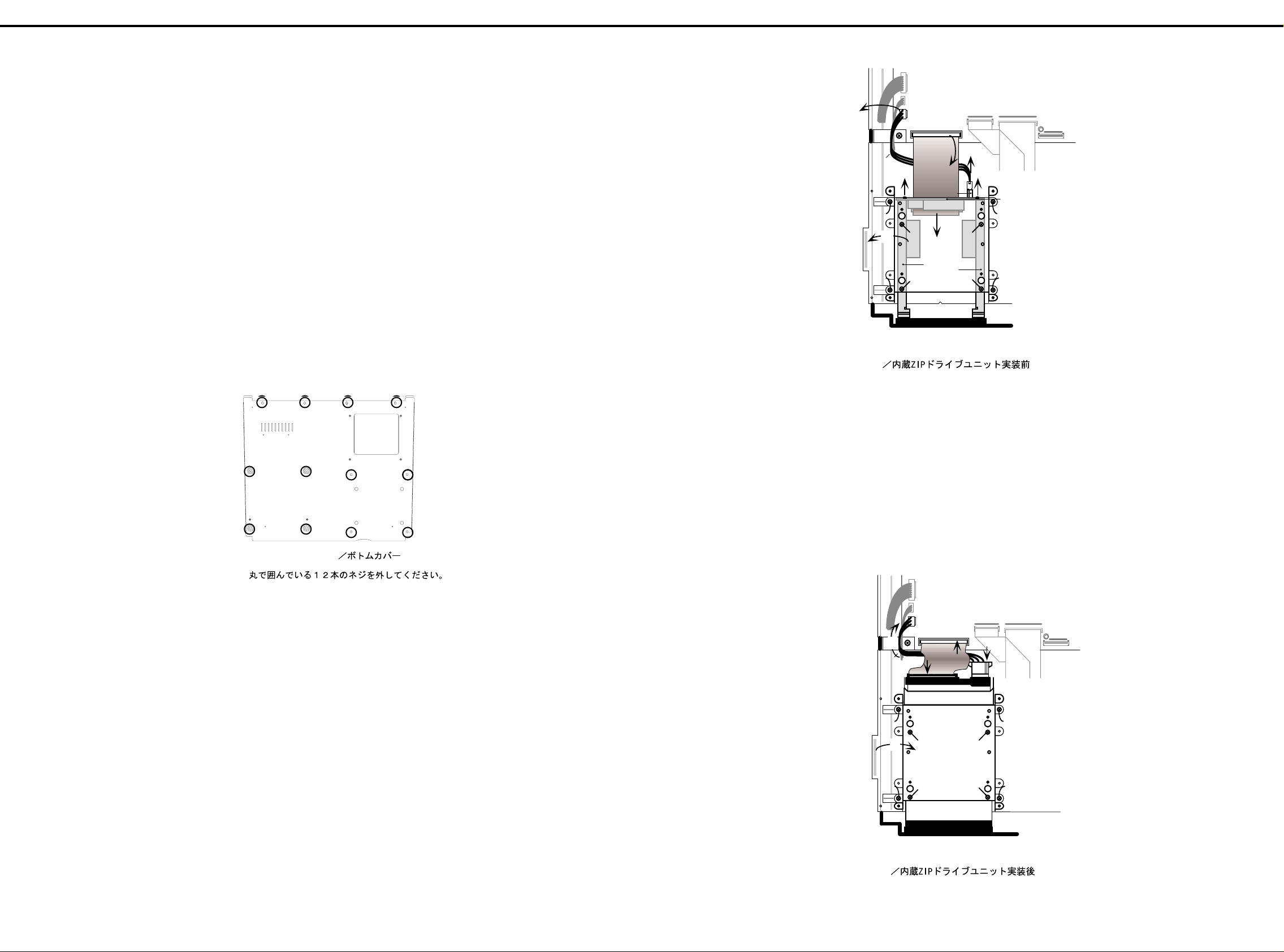
Feb,1999 MC-80
CN107 CN110
CN108
CN111
CN103
CN105
CN106
MC-80 JACK BOARD
WIRING IDE
WIRING
IDE-POWER
DD HOLDER
ANGLE HD-R
ANGLE HD-L
MC-80 IDE BOARD
CN402
CN403
(a)
(a)
(c)
(c)
(c)
(c)
CN401
(d) (d)
(e)
(e)
(b)
(f)
(f) (f)
(f)
fig4.
before installing
the ZIP-INT-1A
8. After securing the ZIP drive to the DD HOLDER with 4
screws, (See fig.5-(g)) connect the WIRING IDE and the
WIRING IDE-POWER to the ZIP drive’s connector
properly.(See fig.5-(h))
9. Secure this DD HOLDER to the boss of a top case with 4
screws. (See fig.5-(i))
10.Connect the WIRING IDE-POWER to the MC-80 JACK
BOARD’s connector(CN103).
And connect the WIRING IDE to the MC-80 JACK
BOARD’s connector(CN111).(See fig.5-(j))
11.After re-sticking a shield sheet to the DD HOLDER, attach
the bottom cover. (See fig.5-(k))
8. DD
ホルダーと
ZIP
ドライブを先ほど外したネジ4本で止
めます。(
fig.5-(g)
参照)
ZIP
ドライブのコネクタに
WIRING IDEとWIRING IDE-
POWER
を挿します。(
fig.5-(h)
参照)
9. ZIP
ドライブの付いたDDホルダーをトップケースのボス
に合わせて、ネジ4本で止めます。(
fig.5-(i)
参照)
10.WIRING IDE-POWER
をジャックボードの
CN103
に挿し
た後、
WIRING IDEをCN111
に挿します。(
fig.5-(j)
参照)
11.
元のようにシールドシートを
DD HOLDER
に貼り付けた
後、ボトムカバーを取り付けます。(
fig.5-(k)
参照)
CN107 CN110
CN108
CN111
CN103
CN105
CN106
MC-80 JACK BOARD
WIRING
IDE-POWER
DD HOLDER
(i)
(i)
(i)
(i)
(h)
(g)
(g) (g)
(g)
(k)
WIRING
IDE
(h)
(j)
(j)
ZIP-INT-1A
fig5. after installing the ZIP-INT-1A
INSTALLING THE INTERNAL ZIP DRIVE UNIT(ZIP-INT-1A) ////
内蔵
内蔵 ZIP ドライブユニット(
内蔵内蔵
♦
♦
NOTICE:
♦ ♦
ドライブユニット(ZIP-INT-1A)の取り付け方法
ドライブユニット(ドライブユニット(
)の取り付け方法
)の取り付け方法)の取り付け方法
◆お読みください
◆お読みください
◆お読みください◆お読みください
When the internal hard disk drive unit(HDP-88) has already
been installed in customer’s MC-80,
Remove it before installing the internal ZIP drive unit as follows.
a. Turn off the power for the MC-80 and any connected
devices, and disconnect any cables connected to the
MC-80.
b. Seeing page "INSTALLING THE INTERNAL HARD DISK
DRIVE UNIT(HDP88)", remove the internal hard disk
drive unit from step8 to step2 in reverse steps.
* Return the internal hard disk drive unit with the MC-80 to
customer.
♦
♦
Procedure:
♦ ♦
1. Turn off the power of the MC-80 and the connected
devices, and disconnect all cables that are connected to
the MC-80.
2. Turn the MC-80 over, and remove the bottom cover.
(See fig.1 to remove 12 screws.)
お客さまの
られている場合、内蔵
以下の手順で内蔵ハードディスクを外しておきます。
a. MC-80
されているすべてのケーブルを外します。
「内蔵ハードディスクドライブユニット(
b.
り付け方法」を参照し、手順8から2へ、逆の手順で内
蔵ハードディスクを外してください。
※ 取り外した内蔵ハードディスクは、
に返却してください。
◆手順
◆手順
◆手順◆手順
1. MC-80
されているすべてのケーブルを外します。
2. MC-80
(外すネジは
に内蔵ハードディスク
MC-80
と接続している機器の電源を切り、
と接続している機器の電源を切り、
を裏返し、ボトムカバーを外します。
fig.1
ドライブユニットを取り付ける前に
ZIP
を参照してください。)
(HDP88)
MC-80
が取り付け
MC-80
HDP88
とともにお客様
MC-80
に接続
)の取
に接続
3. Remove the WIRING IDE and the WIRING IDE-POWER
from the MC-80 JACK BOARD’s connectors
(CN111, CN103). (See fig.4-(a))
4. After taking off a shield sheet from the DD HOLDER
gently,
(See fig.4-(b)) remove 4 screws connecting the DD
HOLDER and the boss of a top case.(See fig.4-(c))
5. Remove 2 screws connecting the MC-80 IDE BOARD and
the ANGLE HD L/R.(See fig.4-(d))
6. Remove the WIRING IDE and the WIRING IDE-POWER
from the MC-80 IDE BOARD’s connectors(CN401,CN402)
on the DD HOLDER.(See fig.4-(e))
7. Remove 4 screws connecting the DD HOLDER and the
ANGLE HD L/R.(See fig.4-(f))
fig.1 Bottom Cover View
fig.1 Bottom Cover View
Remove 12 screws circling in this figure./
Remove 12 screws circling in this figure./
3. WIRING IDEとWIRING IDE-POWER
CN111,CN103
4. DD
た後、(
を止めているネジ4本を外します。(
5. IDE
します。(
取り外したDDホルダーに付いている
6.
WIRING IDEとWIRING IDE-POWERをCN401,CN402
ら外します。(
7. DD
外します。(
から取り外します。(
ホルダーに付いているシールドシートを丁寧にはがし
ボードとアングル
ホルダーとアングル
参照)DDホルダーとトップケースのボス
fig.4-(b)
HD-L/R
参照)
fig.4-(d)
参照)
fig.4-(e)
HD-L/R
参照)
fig.4-(f)
をジャックボードの
fig.4-(c)
IDE
参照)
参照)
ボード上の
fig.4-(a)
を止めているネジ2本を外
を止めているネジ4本を
か
25
Page 26

Feb,1999MC-80
ド
。
。
と
♦
♦ ♦
♦
Procedure:
1. Turn off the power for the MC-80 and any connected
devices, and disconnect any cables connected to the MC-
80.
2. Remove the MC-80’s front cover.
The cover clasp latches onto the body to secure the cover.
(See fig.6)
◆手順
◆手順◆手順
◆手順
1. MC-80
と接続している機器の電源を切り、
MC-80
に接続
されているすべてのケーブルを外します。
2. MC-80
のフロント・カバーを外します。
このカバーは爪部が本体ボディーにひっかかって固定され
ています。(
fig.6
参照)
fig.6
3. Wrap the tip of a flat head screwdriver with a cloth or
similar material and insert it as shown in the figure.
Inserting the screwdriver directly without covering the tip
can scratch the body.Always cover the tip first.(See fig.7)
3.
マイナスドライバーの先を布等で覆って図の位置に差し込
みます。
ドライバーを直接差し込むとボディーに傷がつきます。
必ず布をご用意ください。(
fig.7
参照)
fig.7
4. Gently push the screwdriver downwards to remove the
cover.(See fig.8)
4.
ドライバーを軽く下方に押して、カバーを取り外します。
(
fig.8
参照)
fig.8
12.Checking operation:
a. Connect the AC cord to the MC-80.
b. Turn on the MC-80 power while holding down [CHAIN
PLAY],[REC] and [ARPEGGIATOR] at the same time.
c. Insert a formatted ZIP disk into the ZIP drive after
entering the test mode.
d. After pressing [F6(next)], MC-80 automatically executes
the device checking.
e. The system properly operates, when the ZIP/HD icon is
NOT displayed.
Make sure of the following, when the ZIP/HD icon is
displayed.
IDE -Check the wirings connected properly.
No Disk! -Check the ZIP disk inserted into the formatted
ZIP disk.
13.Executing the operation of shutdown.
a. While holding down the [SHIFT] button, press the [STOP]
button.
b. When "The MC-80 may now be shut down safely"
appears in the display, turn off the power.
* Return the remo ved ANG LE HD L/R (with 2 screws), MC-80
IDE BOARD and excess 2 screws with the MC-80 to
customer.
動作チェックを行います。
12.
a. MC-80
b. [CHAIN PLAY]+[REC]+[ARPEGGIATOR]
c.
d. [F6(NEX T)]
e. ZIP/HD
IDE No Disk! -ZIP
シャットダウン操作を行います。
13.
a. [SHIFT]
b. "The MC-80 may now be shut down safely"
※ 取り外したアングル
および余ったネジ2本は
ください。
の電源ケーブルを接続します。
の電源を投入します。
MC-80
テストモードに入ったら、フォーマット済みの
スクを
す。
ZIP/HD
チェックしてください。
ら、電源を落としてください。
ドライブに挿入します。
ZIP
を押しデバイスチェックを行います。
アイコンが表示されなければ、動作はOK で
アイコンが表示された場合は、以下の点を
ワイヤリングが正しく挿されているか?
ドライブに
を押しながら、
HD-L/R
ディスクが入っているか?
ZIP
を押します。
[STOP]
(ネジ2本付き)と
とともにお客様に返却して
MC-80
を押しながら、
ディ
ZIP
と表示された
ボー
IDE
INSTALLING THE INTERNAL HARD DISK DRIVE UNIT(HDP88) ////
内蔵ハードディスクドライブユニット(
内蔵ハードディスクドライブユニット(HDP88)の取り付け方法
内蔵ハードディスクドライブユニット(内蔵ハードディスクドライブユニット(
The Roland HDP88 Series HARD DISK DRIVE UNIT can be
installed as the internal hard disk.
♦
♦
NOTICE:
♦ ♦
When the internal ZIP drive unit (ZIP-INT-1A) has already been
installed in customer’s MC-80, The parts listed below is
required.
Be sure to take them back from customer.
Part No. Part Name quantity
71123145 IDE BOARD 1
00897812 ANGLE HD-R 1
00897823 ANGLE HD-L 1
40013067 DOUBLE SEMS (SMALL WASHER)
M3x8 ZC
40011101 BINDING TAPTIGHT B 3x8MM BZC 2
As follows, re-install the parts listed above in the MC-80 before
installing the internal hard disk drive unit.
a. Turn off the power for the MC-80 and any connected
devices, and disconnect any cables connected to the
MC-80.
b. Turn the MC-80 over, and remove the bottom cover.
c. Seeing page "INSTALLING THE INTERNAL ZIP DRIVE
UNIT(ZIP-INT-1A)", remove the ZIP drive unit from
step11 to step2 in reverse steps.
d. Re-attach the bottom cover.
2
ローランド
◆◆◆◆ お読みください
お客さまの
が取り付けられている場合、以下の部品が必要になります。必
ずお客さまから回収してください。
部品番号 品目名称 数量
71123145 IDE BOARD ASSY 1
00897812 ANGLE HD-R 1
00897823 ANGLE HD-L 1
40013067 DOUBLE SEMS (SMALL WASHER)
40011101 BINDING TAPTIGHT B 3x8MM BZC 2
内蔵ハードディスクドライブユニットを取り付ける前に上記の
部品を以下の手順で
)の取り付け方法
)の取り付け方法)の取り付け方法
シリーズのハードディスクを内蔵できます
HDP88
お読みください
お読みくださいお読みください
に内蔵
MC-80
M3x8 ZC
MC-80
a. MC-80
b. MC-80
c.
d.
と接続している機器の電源を切り、
されているすべてのケーブルを外します。
を裏返し、ボトムカバーを外します。
「内蔵
方法」を参照し、手順11から3へ、逆の手順で内蔵
ドライブユニットを外してください。
ボトムカバーを取り付けます。
ドライブユニット(
ZIP
ドライブユニット
ZIP
に取り付けておく必要があります
ZIP-INT-1A
(ZIP-INT-1A)
2
に接続
MC-80
)の取り付け
ZIP
* Return the ZIP drive unit with the MC-80 to customer.
26
※ なお取り外した内蔵
もにお客様に返却してください。
ドライブユニットは、
ZIP
MC-80
と
Page 27

Feb,1999 MC-80
5. Remove the screws from the positions shown in the figure.
(The screws removed are use to affix the hard disk in Step
7.)(See fig.9)
6. With the hard disk’s warning sticker facing upwards,gently
insert the hard disk into the installation slot, and check to
make sure the unit has been fully inserted.
7. Using the screws removed in Step 5, reattach the hard
disk.
8. After repositioning the grip on the front hard disk, return the
front panel cover to its original position. (See fig.10)
a.
図の位置に取り付けてあるネジを外します。
5.
(取り外したネジは手順7でハードディスクを固定する
のに使用します。)(
fig.9
ハードディスクの注意書きシールが貼ってある面を上に向
6.
け、取り付け口にゆっくり差し込み、奥まで確実に差し込
みます。
手順5で取り外したネジを使って、ハードディスクを固定
7.
します。
ハードディスク前面の取っ手を収めた後、フロント・パネ
8.
ルのカバーを元通りに取り付けます。(
b. c.
fig.9
参照)
fig.10
参照)
a. First align the upper part.
Getting the cover as close to vertical as possible makes it
easier to fit.
b. Press at the point indicated by the arrow in the figure.
c. The clasp secures the cover.
9. Initialize the hard disk.
Connect the AC Cord and turn on the MC-80 power.
a. Press [TOOLS].
b. Press [F5 (DISKUTIL)].
c. Press [F6 (MENU)] to select “DISK MENU”.
d. Press [F4 (FORMAT)].
e. Press [F1(DRIVE)] several times to select the hard disk.
f. Press [F6 (FORMAT)].
g. Display shows "MC-80HD".
h. Press [F6 (FORMAT)].
i. Display shows the warning window of "All the data on the
disk will be lost".
Press [F6 (FORMAT)].The format is executed.
j. When formatting is finished, "Completed." appears in the
display.
Press [F6(ACCEPT)].
k. Press [SEQUE NCE R] to ret u rn to the "SON G PLAY"
window.
fig.10
まず、上部を合わせます。
a.
カバーをなるべく垂直に近い角度であてると、はめ込み
やすくなります。
矢印の位置を押します。
b.
爪がかかります。
c.
ハードディスクの初期化を行います。
9.
a.[TOOLS
b.[F5(DISKUTIL
c.[F6(MENU
d.[F4(FORMAT
e.[F1(DRIVE
f.[F6(FORMAT
g. LCDに"MC-80HD"
h.[F6(FORMAT
i.
j.
k.[SEQUENCER]
の電源ケーブルを接続し、電源を投入します。
MC-80
]を押します。
)]を押します。
)]を押して
)]を押します。
)]を押して、ハードディスクを選びます。
)]を押します。
「ディスク内のデータが消去されるがよいか」という確認
画面が表示がされます。
[F6(
FORMAT
ます。
フォーマットを実行し終了すると、
示されます。
[F6(ACCEPT)]
ておきます。
)]を押します。
)]を押します。フォーマットが実行され
を押します。
を押して、
"DISK MENU"
と表示されます。
SONG PLAY
を選びます。
Completed.
画面に戻し
と表
10.Executing the operation of shutdown.
a. While holding down the [SHIFT] button, press the [STOP]
button.
b. When "The MC-80 may now be shut down safely"
appears in the display, turn off the power.
シャットダウン操作を行います。
10.
a. [SHIFT]
b. "The MC-80 may now be shut down safely"
を押しながら、
ら、 電源を落としてください。
[STOP]
を押します。
と表示された
27
 Loading...