

Page 1
Reference Manual
© 2019 Roland Corporation
01
Page 2

Contents
Panel Descriptions
:Top Panel
:Rear Panel
.................................... 5
(Connecting Your Equipment)
Introduction
:Turning the MC-707 On
Turning O the Power
An Overview of the MC-707
:What Is a Project?
:What Is a Track?
:What Is a Clip?
:What Is the Browser?
:Total Eect Settings
:USER SAMPLE
Basic Operation
:Loading and Playing a Project
:Changing the Clips that Play
:Selecting a Tone or Drum Kit
:Importing a Clip
Main Screen
:HOME Screen
:Selecting a Clip
:Editing a Track or Clip
Creating a Clip
Editing the Sound
Editing the Clip Settings
Copying the Sound or Phrase of a Clip
Renaming a Clip
Reloading a Clip
Deleting
................................... 14
(DELETE)
Project Operations
:What Is a Project?
:Loading a Project
:Managing Projects
:Creating a New Project
:Making Project Settings
:Managing Samples Loaded into a Project
:Saving a Project
Track Operations
:Creating a Track
:Changing a Track to a Dierent Type
:Making Track Settings
............................ 5
.................................. 8
......................... 8
............................. 8
................... 9
.............................. 10
............................... 10
................................ 10
........................... 10
............................ 10
................................. 10
............................... 11
................... 11
..................... 11
..................... 11
............................... 12
................................. 14
............................... 14
([C4] Knob)
(CREATE)
............................ 14
(SOUND)
.......................... 14
(SETTING)
(RENAME)
.......................... 15
(RELOAD)
........................... 16
................... 14
..................... 14
(COPY/PASTE)
................................. 16
............................ 17
.............................. 17
.............................. 17
............................. 17
......................... 17
........................ 18
............................... 19
.............................. 20
............................... 20
.......................... 20
................ 7
......... 15
(Sample Bank)
19
.............. 20
Pad Operations
:Using Mute Mode
Stopping/Playing Tracks
Muting a Track
:Using Cue Mode
Stopping/Playing Tracks
Using the Cue Function
:Using Clip Mode
Switching Clips
Making Clip Mode Settings
:Using Note Mode
Playing
....................................... 23
DRUM PAD MUTE
Making Note Mode Settings
:Using Chord Mode
Playing
....................................... 23
Editing a Chord
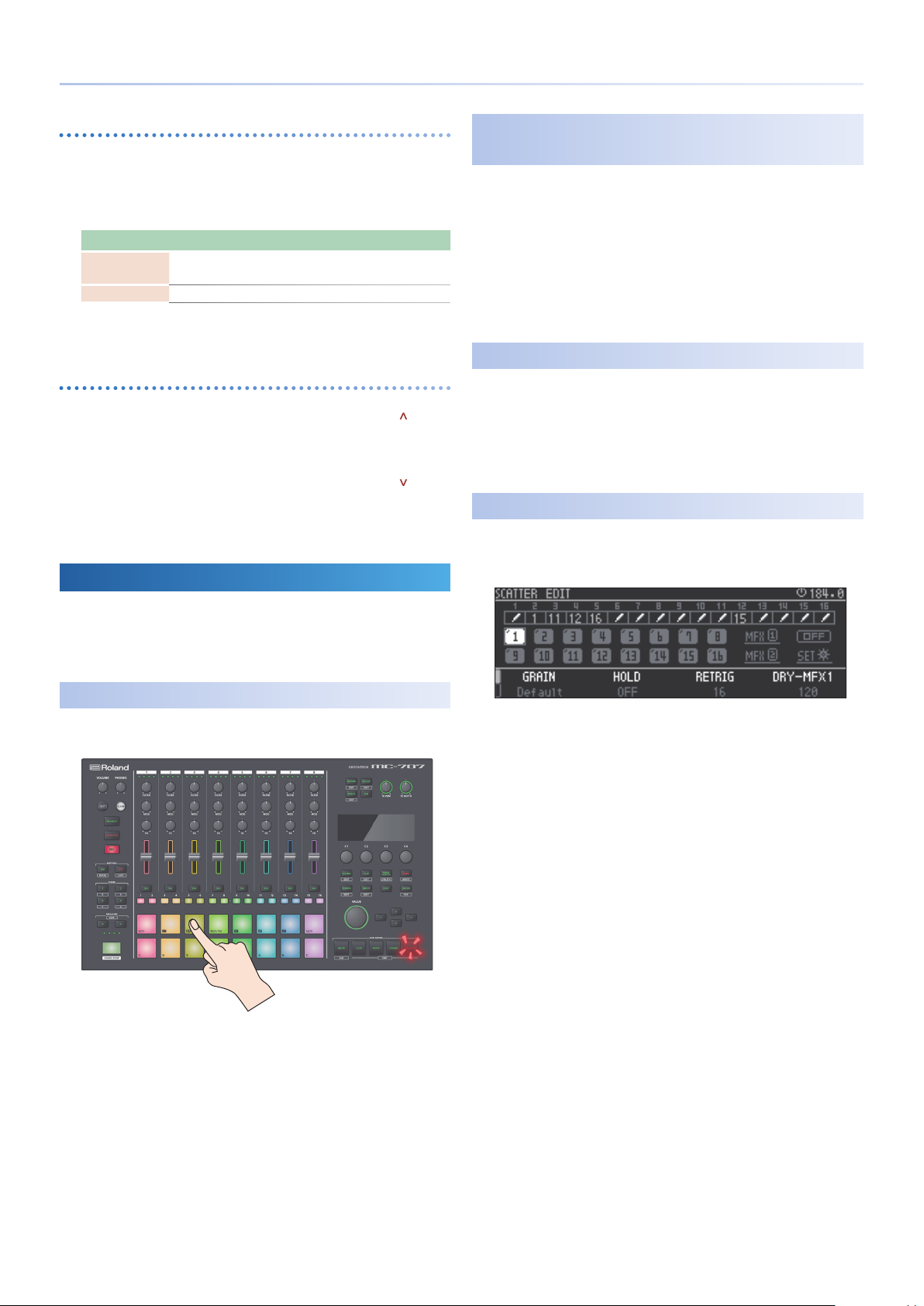
:Scatter Mode
Using the Pads to Apply the Eect
Using the [SCATTER] Button to Apply the Eect
Recording Eects in Steps
Making Scatter Settings
Importing Clips
Selecting Sounds
:Loading a Preset Sound
:Loading from a Project on the SD Card
:Loading Samples from the SD Card
(PAD MODE)
............................. 22
(Pads [9]–[16])
............................... 22
............................... 22
................................. 22
.............................. 22
................................ 23
............................. 23
................................. 23
................................. 24
(Clip Browser)
(Sound Browser)
Step-Recording a Phrase
:Tone Track
Changing the Measure Settings
Automatically Advancing the Step During Input
(Step Input Mode)
Editing the Notes of Each Step
:Drum Track: TR-REC
Increasing the Measures
Editing the Steps
Track Pad Mute
Clip Pad Mute
:Specifying the Last Step and First Step
Specifying the Last Step
Specifying the First Step
Deleting the First Step and Last Step
Recording
:Recording a Performance to a Tone or Drum Track
:Recording Audio on a Looper Track
................................... 28
.................................. 28
............................ 30
................................ 30
................................. 30
.................................. 30
..................................... 32
..................... 22
(Pads [1]–[8])
................... 22
......................... 22
(Pads [1]–[8])
(Pads [9]–[16])
................... 22
................... 22
. . . . . . . . . . . . . . . . . . . . . . . . . 22
........................ 23
.................... 24
........... 24
.......................... 24
........................... 24
.................... 25
................ 26
......................... 26
............ 26
............... 26
...................... 28
...................... 28
....................... 29
........................... 30
............ 31
........................... 31
........................... 31
.................. 31
............... 32
... 32
Quantize
:Enabling Quantize During Recording
:Specifying Playback Quantization
...................................... 33
.............. 33
................ 33
2
Page 3

Contents
Recording Knob Movement in Steps
Turning Motion On/O
Recording Motion
Deleting Motion
Editing Motion
Saving and Recalling a Scene
:Recalling a Scene
:Storing a Scene
Total Eects
:Using the [FX PRM] [FX DEPTH] Knobs and the [ON]
Button to Select the Target of Operation
:Editing Reverb or Delay
:Editing MFX/COMP/EQ
:Changing the Knob Assignments
SCATTER
:Applying the Scatter Eect
Using the Pads to Apply the Eect
Pressing the [SCATTER] Button to Apply the Eect
:Editing the Scatter Eect
Detailed Editing
................................... 37
...................................... 38
Editing the TONE Track
:Simple Sound Editing
:Detailed Sound Editing
How a Tone Is Constructed
PARTIAL EDIT Screen
COMMON SETTING Screen
............................ 34
............................... 34
................................. 34
.................................. 34
................. 36
.............................. 36
............................... 36
......................... 37
......................... 37
................. 37
...................... 38
.................... 38
........................ 38
................................. 39
........................ 41
.......................... 41
......................... 43
......................... 43
.............................. 44
......................... 44
(MOTION)
........... 37
......... 38
.. 34
Assigning Parameters to the Knobs
(KNOB ASSIGN)
:Operating the Unit
Returning Parameter Values to the Default Value
Tempo Settings
:Master Clock
Master Clock Settings
:Tap Tempo
Input and Output Settings
:Input and Recording Settings
:Using an External Eect
:Individually Outputting Each Track
UTILITY
:System Settings
:Initializing a New SD Card
:Returning to the Factory Settings
:Optimizing the Internal Memory
:Using a Connected Computer to Manage the SD Card
List of Shortcut Keys
:Switching Screens and Modes
:Adjusting the Mix Sound
:MOTION
:Phrase Editing
:Performance
:Controller Values and Parameter Editing
................................... 51
............................. 51
.......... 51
............................... 52
.................................. 52
............................. 52
................................... 52
.................... 53
(INPUT/REC)
(SEND/RETURN Jacks)
........... 53
.......... 53
(ASSIGNABE OUT)
....................................... 54
(SET)
........................... 54
(FORMAT)
................ 55
(FACTORY RESET)
(LOOPER OPTIMIZE)
.......................... 57
................... 57
........................ 57
..................................... 57
................................ 57
.................................. 58
........... 58
... 53
..... 55
.... 55
56
Editing the DRUM Track
:Simple Sound Editing
:Pad Settings
Changing the Pad’s Sound
Editing an Instrument
Editing a Sample
Editing the Instrument Name
Pad Editing
Initializing an Instrument
(PAD MENU)
(PAD EDIT)
LOOPER Track
:Making Looper Settings
Playback Settings
Editing the Sample's Waveform
(Playback Region and Time Stretch Settings)
MFX Editing
Editing the Sample Name
.................................... 49
.......................... 45
......................... 46
(Instrument) (INST SELECT)
(INST EDIT)
(SAMPLE EDIT)
.............................. 47
(INIT INST)
................................. 48
................................ 48
.......................... 49
Editing a Clip’s Settings
:Tone Tracks or Drum Tracks
:LOOPER
...................................... 50
. . . . . . . . . . . . . . . . . . . . . . . 45
.......... 46
...................... 46
....................... 46
(INST NAME EDIT)
............. 47
.................... 47
........................ 48
................... 48
....................... 50
...................... 50
Error Message List
............................ 59
Interoperation with Other Devices
:Synchronizing with a DAW
:Synchronizing with a TR-8S
...................... 60
...................... 60
............ 60
3
Page 4

Contents
Parameter List
:ZEN-Core Tone Parameter
SOUND
STRUCTURE
OSC MOD COM
UNISON
PTL CTRL
PTL RANGE
TUNING
Part Parameter
INFO
......................................... 65
OSC
......................................... 65
Pitch
......................................... 66
PITCH ENV
FILTER
........................................ 67
FLITER ENV
AMP
......................................... 69
AMP ENV
LFO1 / LFO2
STEP LFO1/ STEP LFO2
PARTIAL EQ
OUTPUT
CONTROL
MATRIX CONTROL
MFX
......................................... 74
MFX CTRL
:Drum Kit Tone Parameters
SOUND
MFX
......................................... 75
KIT MFX CTRL
DRUM COMP1–6
PAD CTRL
PAD EQ
. . . . . . . . . . . . . . . . . . . . . . . . . . . . . . . . . . . . . . . 75
INST COMMON
INST WAVE
INST PENV
INST FILTER
INST FENV
INST AENV
:Total Eect Parameters
COMP
........................................ 80
EQ
.......................................... 80
MFX
......................................... 80
EQ
(Part 1–4)
:DELAY
Delay Parameters
:REVERB
Reverb Parameters
................................ 61
(Z-Core)
................. 61
....................................... 61
.................................... 62
................................. 62
...................................... 63
...................................... 63
.................................... 63
....................................... 64
(KNOB CTRL)
. . . . . . . . . . . . . . . . . . . . . . . . . . 64
..................................... 67
.................................... 69
...................................... 70
.................................... 70
............................ 71
.................................... 72
...................................... 72
..................................... 72
............................... 73
..................................... 74
(Drum)
................. 75
....................................... 75
................................... 75
................................ 75
..................................... 75
................................. 76
..................................... 76
..................................... 77
.................................... 78
..................................... 78
..................................... 79
......................... 80
.................................... 81
....................................... 81
................................ 81
...................................... 82
............................... 82
MFX/IFX Parameters
:Note
........................................ 120
Block Diagram
................................ 121
.......................... 84
4
Page 5
Panel Descriptions
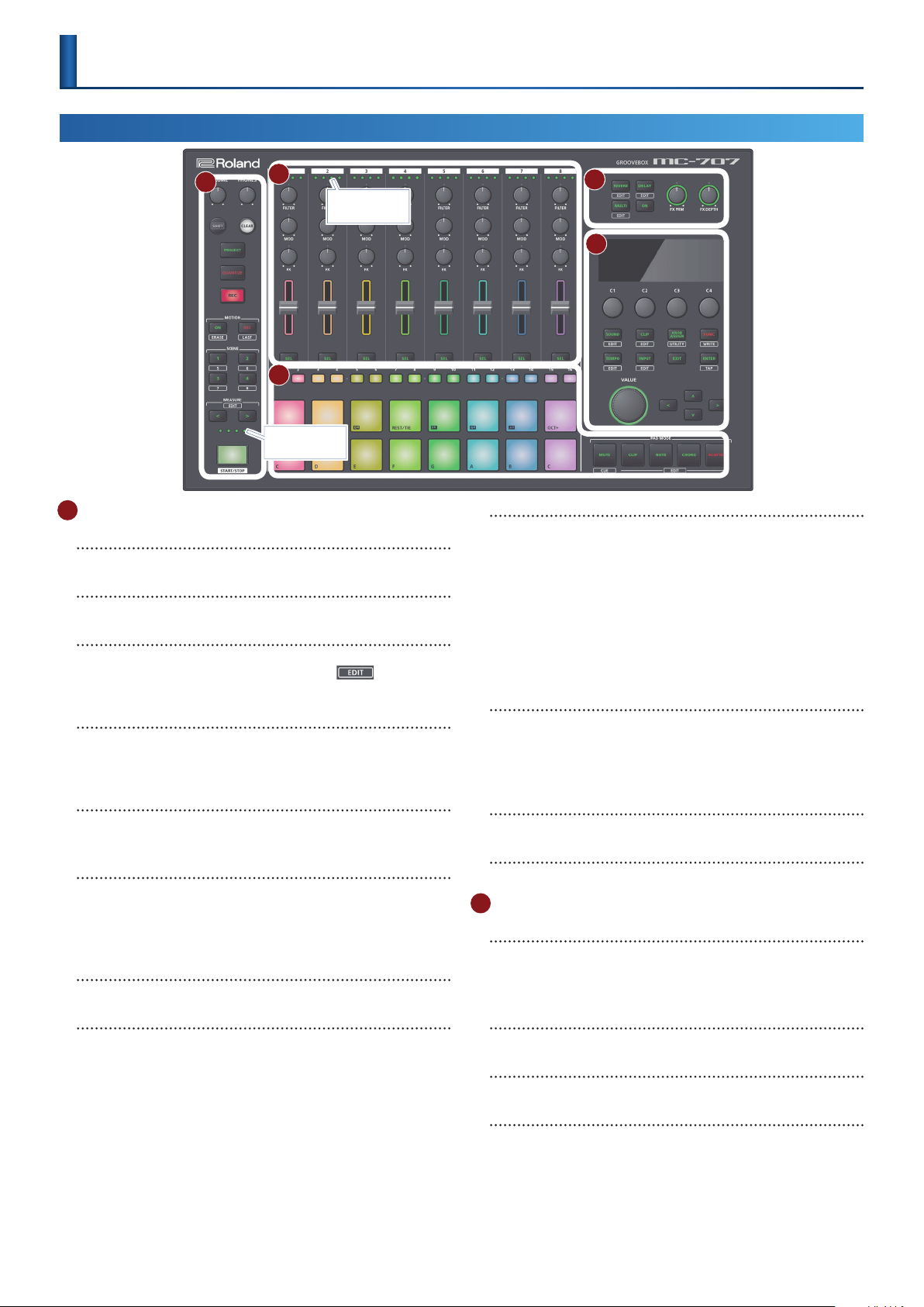
Top Panel
1
1 Common Section 1
[VOLUME] knob
Adjusts the volume of the MIX OUT jacks.
[PHONES] knob
Adjusts the volume of the PHONES jack.
[SHIFT] button
When you hold down the [SHIFT] button and press a button
that’s labeled with a function name (such as ), that
function is executed.
[CLEAR] button
Pressing the [CLEAR] button in conjunction with another button,
you can clear the recorded content of the step sequencer or a
phrase.
[PROJECT] button
Accesses the project menu screen.
Here you can load a project and make settings for it.
[QUANTIZE] button
Switches on/o quantization during recording. Press this
together with the [SHIFT] button to access the quantization
settings screen.
For details, refer to“Quantize” (p. 33).
&
[REC] button
Lets you record using the pads, or record into the looper.
2
3
Measure indicators
Playback position
indicators
4
5
SCENE [1]–[4] button
The combination of clips being played back by the tracks of the
MC-707 is called a “scene.”
You can recall a stored scene by pressing a SCENE [1]–[4] button.
By holding down the [SHIFT] button and pressing a SCENE [1]–[4]
button you can recall scenes 5–8.
To store the current settings as a scene, long-press the SCENE
button in which you want to store the settings.
To store the settings in a scene 5–8, hold down the [SHIFT]
button and long-press a SCENE button.
MEASURE [<] [>] buttons
Move to the measure that you want to edit.
If you hold down the [SHIFT] button and press a MEASURE [<] [>]
button, the measure length edit screen appears.
For details, refer to“Increasing the Measures” (p. 30).
&
Measure indicators
The four indicators show the measure that you’re editing.
[START/STOP] button
Starts or stops playback.
2 Mixer Section
Playback position indicators
These indicate the playback position of the clip as a percentage
(%).
One indicator means 25%, and all indicators lit mean 100%.
MOTION [ON] [REC] button
Lets you record knob movements for each clip, and play them
back as motions.
MOTION [ON] button
Plays back a recorded motion.
By holding down the [SHIFT] button and pressing the MOTION
[ON] button, you can delete a motion.
MOTION [REC] button
Records a motion.
By holding down the [SHIFT] button and pressing the MOTION
[REC] button, you can edit the LAST STEP.
* 1 LAST STEP: The loop end setting that you can specify for each clip.
(*1)
[FILTER] knob, [MOD] knob, [FX] knob
These knobs adjust the assigned parameters.
Level faders
Adjusts the volume.
[SEL] button
Selects a track.
If you hold down the [SHIFT] button and press a [SEL] button, the
track setting menu appears.
For details, refer to“Making Track Settings” (p. 20).
&
5
Page 6
Panel Descriptions
3 Pad Section
Step [1]–[16] buttons
Use these buttons to select the step that you want to edit.
Their operation and indications change depending on the pad
mode and the settings.
(16 pads)
Pads
The operation of the pads depends on the pad mode that’s
selected.
PAD MODE [MUTE] button
Switches the pads to MUTE mode (p. 22). In MUTE mode, you
can use the pads to mute tracks or stop clips.
If you hold down the [SHIFT] button and press the PAD MODE
[MUTE] button, the pads switch to CUE mode. In CUE mode, only
the selected track is output from the PHONES jack.
PAD MODE [CLIP] button
Switches the pads to CLIP mode (p. 22). In CLIP mode, the pads
select the clip to play or edit.
By holding down the [SHIFT] button and pressing the PAD MODE
[CLIP] button, you can make clip-related settings.
PAD MODE [NOTE] button
Switches the pads to NOTE mode (p. 22). In NOTE mode, you
can use the illuminated pads to perform as on a keyboard.
By holding down the [SHIFT] button and pressing the PAD MODE
[NOTE] button, you can make settings related to NOTE mode.
PAD MODE [CHORD] button
Switches the pads to CHORD mode (p. 23). In CHORD mode,
you can use each pad to play a chord.
By holding down the [SHIFT] button and pressing the PAD MODE
[CHORD] button, you can make settings related to CHORD mode.
PAD MODE [SCATTER] button
Switches the pads to SCATTER mode. Scatter is an eect that is
synchronized to the beat. It can give a digital-feeling groove to
the playback.
By holding down the [SHIFT] button and pressing the PAD MODE
[SCATTER] button, you can make settings related to scatter.
For details, refer to “SCATTER” (p. 38).
&
4 Tatal Eect Section
[REVERB] [DELAY] [MULTI] buttons
Switch the functions of the [FX PRM] [FX DEPTH] knobs.
By holding down the [SHIFT] button and pressing these buttons,
you can edit the total eect.
[ON] button
Turns on/o the eects selected by the [REVERB], [DELAY], and
[MULTI] buttons.
[SOUND] button
Accesses the sound browser screen.
By holding down the [SHIFT] button and pressing the [SOUND]
button, you can access the sound settings screen.
For details, refer to “Simple Sound Editing” (p. 41).
&
[CLIP] button
Accesses the clip browser screen.
If you hold down the [SHIFT] button and press the [CLIP] button,
the clip settings screen appears.
For details, refer to “Editing a Clip’s Settings” (p. 6).
&
[KNOB ASSIGN] button
The KNOB ASSIGN screen appears.
If you hold down the [SHIFT] button and press the [KNOB
ASSIGN] button, the UTILITY screen appears.
For details, refer to “UTILITY” (p. 54).
&
[FUNC] button
The function screen appears.
If you hold down the [SHIFT] button and press the [FUNC]
button, the project save screen appears.
[TEMPO] button
By pressing the [TEMPO] button to make it light and then turning
the [VALUE] dial, you can set the BPM.
If you hold down the [SHIFT] button and press the [TEMPO]
button, the master clock setting screen appears (p. 52).
[INPUT] button
By pressing the [INPUT] button to make it light and then turning
the [VALUE] dial, you can adjust the input volume from the EXT
IN jacks.
If you hold down the [SHIFT] button and press the [INPUT]
button, a setting screen for input/output and recording-related
settings appears.
For details, refer to “Input and Output Settings” (p. 53).
&
[EXIT] button
Returns to the previous screen.
In some screens, cancels the currently-executing function.
[ENTER] button
Conrms a selection or operation.
By holding down the [SHIFT] button and pressing the [ENTER]
button, you can use this as tap tempo.
[VALUE] dial
If the [TEMPO] button is lit, the dial changes the BPM value. If the
INPUT button is lit, the dial sets the EXT IN jack's input volume.
If the [TEMPO] button and [INPUT] button are unlit, use the
dial to edit a value or scroll the screen. The operation changes
depending on what's shown in the screen.
[FX PRM] [FX DEPTH] knob
Adjust the eect depth.
5 Common Section 2
Display
Shows necessary information for various operations.
[C1]–[C4] knob
Necessary functions are assigned to these knobs depending on
the operation.
You can also press the [C1]–[C4] knobs.
6
Cursor [ ] [ ] [<] [>] buttons
Move the cursor position up, down, left, or right.
Alternatively, these buttons switch between screens.
Page 7
Panel Descriptions
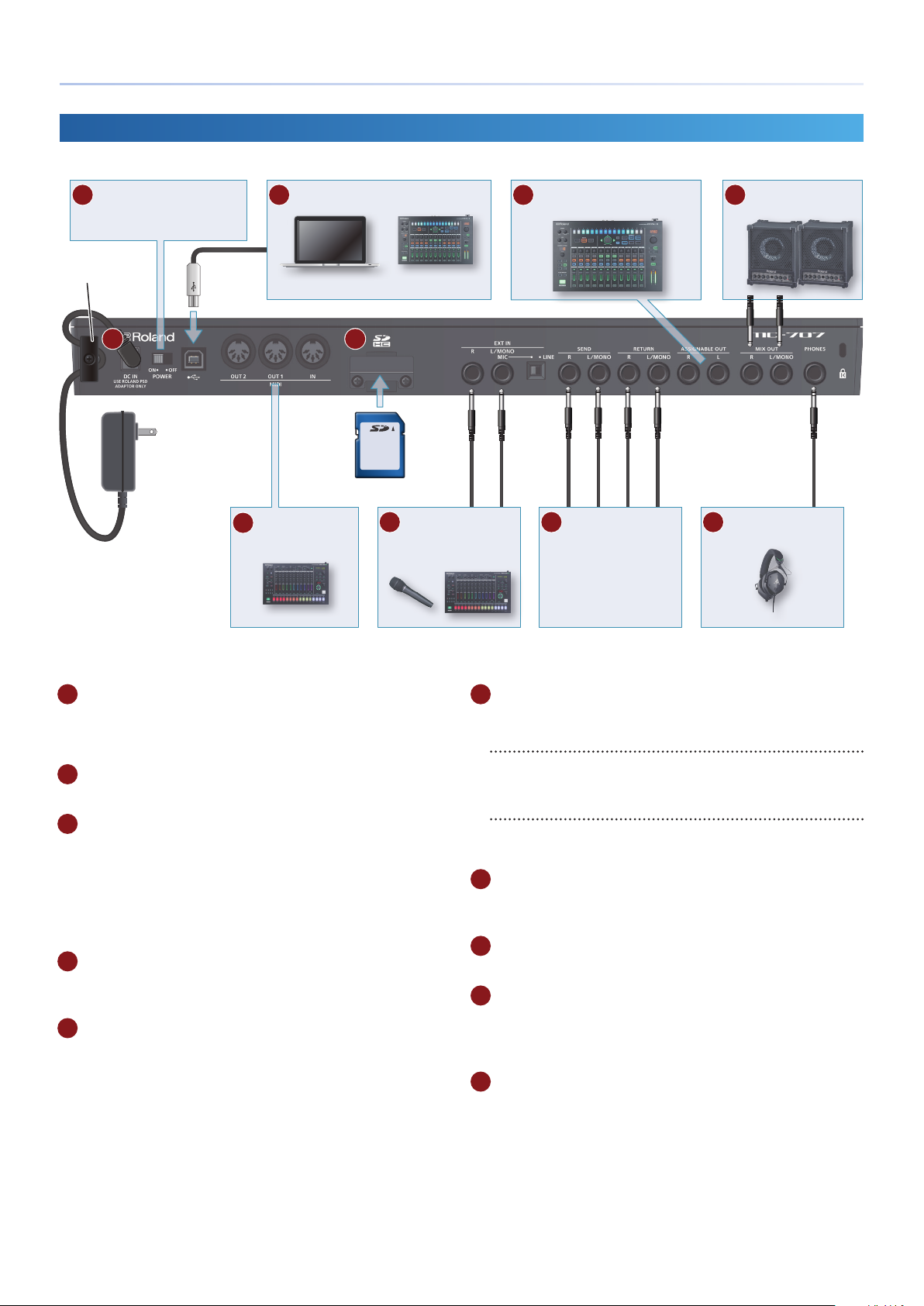
Rear Panel
* To prevent malfunction and equipment failure, always turn down the volume, and turn o all the units before making any connections.
B [POWER] switch
“Turning the MC-707 On”
&
(p. 8)
Cord hook
A
AC Adaptor
(Connecting Your Equipment)
C USB port
Computer MX-1
D MIDI port
Connect MIDI devices.
E
SD card
F EXT IN jacks
Connect a microphone or
audio device.
H ASSIGNABLE OUT jacks
G SEND jacks
RETURN jacks
Connect an external eect
unit.
I MIX OUT jacks
J PHONES jack
TR-8S
A DC IN jack
Connect the included AC adaptor here.
* Use the cord hook to secure the cord of the AC adaptor as shown in the
illustration.
B [POWER] switch
Turns the power on/o.
C USB port
Use a commercially available USB 2.0 cable (type B) to connect this
port to your computer. It can be used to transfer USB MIDI and USB
audio data. You must install the USB driver when connecting the
MC-707 to your computer. For details, refer to Readme.htm in the
downloaded le.
https://www.roland.com/support/
&
D MIDI port
Connect these to external MIDI equipment to transmit and receive
MIDI messages.
E SD card slot
With the factory settings, the SD card protector is fastened with
the included SD card inserted. If you want to take out the SD card,
remove the screws.
The SD card contains various data (settings, sounds, samples, etc.)
for this unit.
* Never turn o the power or remove the SD card while the screen indicates
“Processing...”
* Some memory card types or memory cards from some manufacturers may not
record or play back properly on the unit.
F EXT IN
These are audio input jacks.
EXT IN L/MONO, R jacks
You can connect a dynamic microphone or an instrument here.
Connect a microphone to the L/MONO jack.
[MIC/LINE] switch
Set this switch appropriately for the device that’s connected.
This switches the gain of the L/MONO jack.
G SEND (L, R) jacks/RETURN (L, R) jacks
These jacks let you connect an external eect unit and use it as a
track eect or total eect.
H ASSIGNABLE OUT jack
You can output a specic track from the ASSIGNABLE OUT jacks.
I MIX OUT (L/MONO, R) jacks
These are audio output jacks. Connect them to your amp or
monitor speakers.
If you’re outputting in mono, connect the L/MONO jack.
J PHONES jack
You can connect a set of headphones here.
7
Page 8

Introduction
Turning the MC-707 On
* Before turning the unit on/o, always be sure to turn the volume down. Even
with the volume turned down, you might hear some sound when switching the
unit on/o. However, this is normal and does not indicate a malfunction.
Power-on your equipment in the order of MC-707 0
1.
connected equipment.
Power-on the connected equipment, and raise the volume
2.
to an appropriate level.
Turning O the Power
Power-o your equipment in the order of connected
1.
equipment 0 MC-707.
8
Page 9
An Overview of the MC-707
MFX SettingMFX Setting
MFX SettingMFX Setting
MFX SettingMFX Setting
MFX SettingMFX Setting
MFXMFX
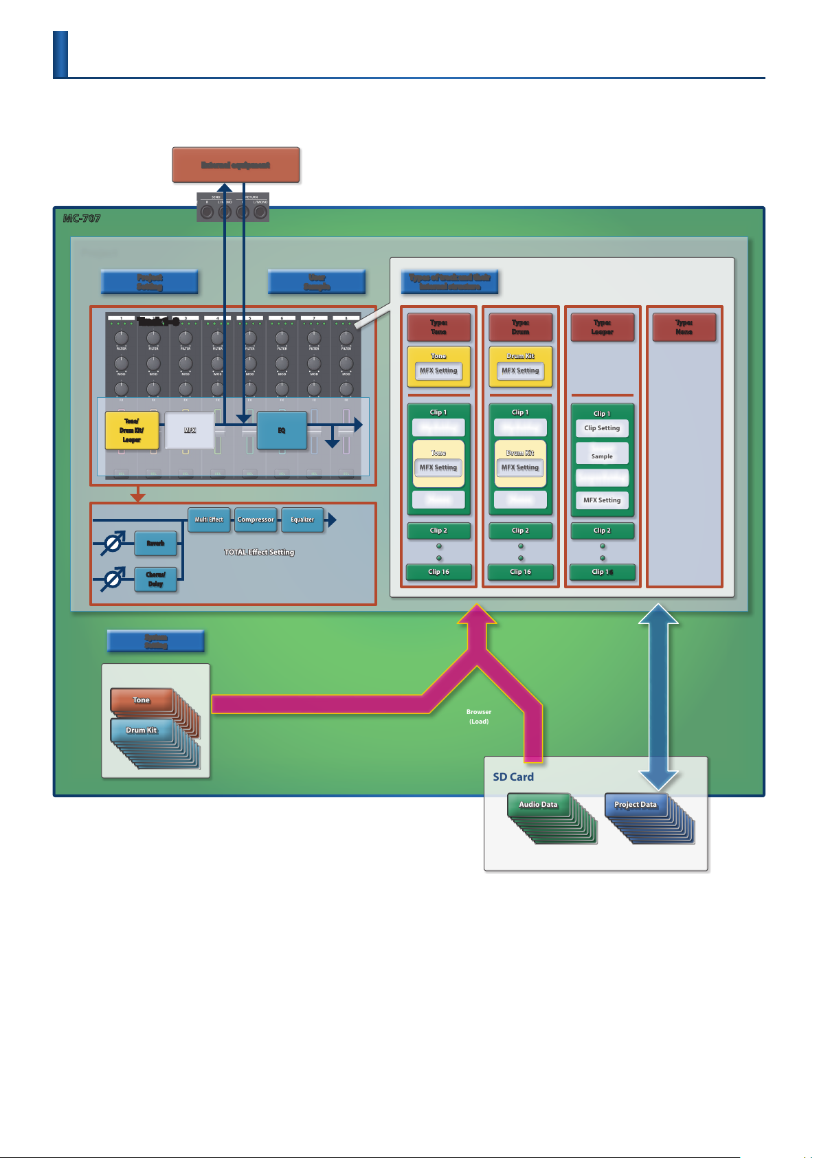
The MC-707 can simultaneously play back up to eight independent tracks.
You can assign up to 16 clips to each track, and switch between these clips during playback.
External equipment
SEND jacks
RETURN jacks
MC-707
Project
Track Mix
Track 1–8
Track 1–8
Preset
Tone/
Drum Kit/
Looper
Tone
Drum Kit
Project
Setting
Track 1–8
Reverb
Chorus/
Delay
System
Setting
Multi Eect
EQ
Compressor
TOTAL Eect Setting
User
Sample
To track mix
To reverb send or
chorus/delay send
Equalizer
MIX OUT
Types of track and their
internal structure
Type:
Tone
Tone
Clip 1
Clip Setting
Tone
Phrase
Clip 2
Clip 16
Browser
(Load)
Type:
Drum
Drum Kit
Clip 1
Clip Setting
Drum Kit
Phrase
Clip 2
Clip 16
Type:
Looper
Clip 1
Clip Setting
Looper
Sample
Looper Setting
MFX Setting
Clip 2
Clip 16
Type:
None
Save
Load
SD Card
Project DataAudio Data
9
Page 10

An Overview of the MC-707
What Is a Project?
On the MC-707, data for one song is handled as a unit called a “project.”
Projects are saved on an SD card.
A project contains data for tracks, clips, tones, and the samples that are
used.
If you want to keep the content that you edited, save the project.
What Is a Track?
There are three types of track.
Tone: A track that mainly handles clips that have
pitch.
Drum: A track that handles drum and percussion
clips.
Looper: A track that handles audio loops. You can
import audio data from an SD card, or
record sound that’s input from the EXT IN
jacks or from a track. Time stretch is also
supported.
What Is a Clip?
A “clip” is a collection of data to be played back by a track. The data
included in a clip diers depending on the type of track.
Track type: Tone
Clip setting: This contains the name of the clip, and
information and settings for the clip.
Tone: This contains settings for the sound. It also
includes eect (MFX) settings. (*1)
Phrase: This is performance data and data that
creates changes in the sound (MOTION).
Track type: Drum
Clip setting: This contains the name of the clip, and
information and settings for the clip.
Drum kit: This contains settings for the sound. It also
includes eect (MFX) settings.
Phrase: This is performance data and data that
creates changes in the sound (MOTION).
(*1)
What Is the Browser?
This lets you select the material that you need for the project that
you’re working on.
Selecting preset tones and drum kits
You can browse the preset tones and drum kits, and use them.
Selecting from a project on the SD card
You can browse clips, tones, and drum kits, and use them.
Selecting from audio les on the SD card
You can use these as looper samples to be played by a looper track.
You can also use them as user samples for a tone or drum kit.
Total Eect Settings
The MC-707 is equipped with ve total eects.
Settings for these eects are saved in the project.
Reverb
5
Adds reverberation to the sound.
Chorus/Delay
5
Gives the sound depth and spaciousness (Chorus), or delays the
sound in an echo-like manner (Delay).
Compressor
5
Compresses loud peaks of the master output, making the volume
more consistent.
Multi FX
5
Lets you select and use one of various eects such as lter or
overdrive.
Equalizer
5
An equalizer with three frequency bands (low, mid, high).
USER SAMPLE
“User samples” are waveform data that can be used by a tone or drum
kit.
Audio les saved on an SD card can be imported into a project.
For details, refer to “Importing Clips (Clip Browser)” (p. 25).
&
Track type: Looper
Clip setting: This contains the name of the clip, and
information and settings for the clip.
Looper sample: This is the audio data played by the looper.
Looper setting: This contains settings that specify how the
looper sample is played.
MFX: This contains eect (MFX) settings.
Phrase: This contains data that creates changes in
the sound (MOTION).
* 1 Alternatively, you can use the track’s settings instead of the clip’s settings.
10
Page 11
Basic Operation
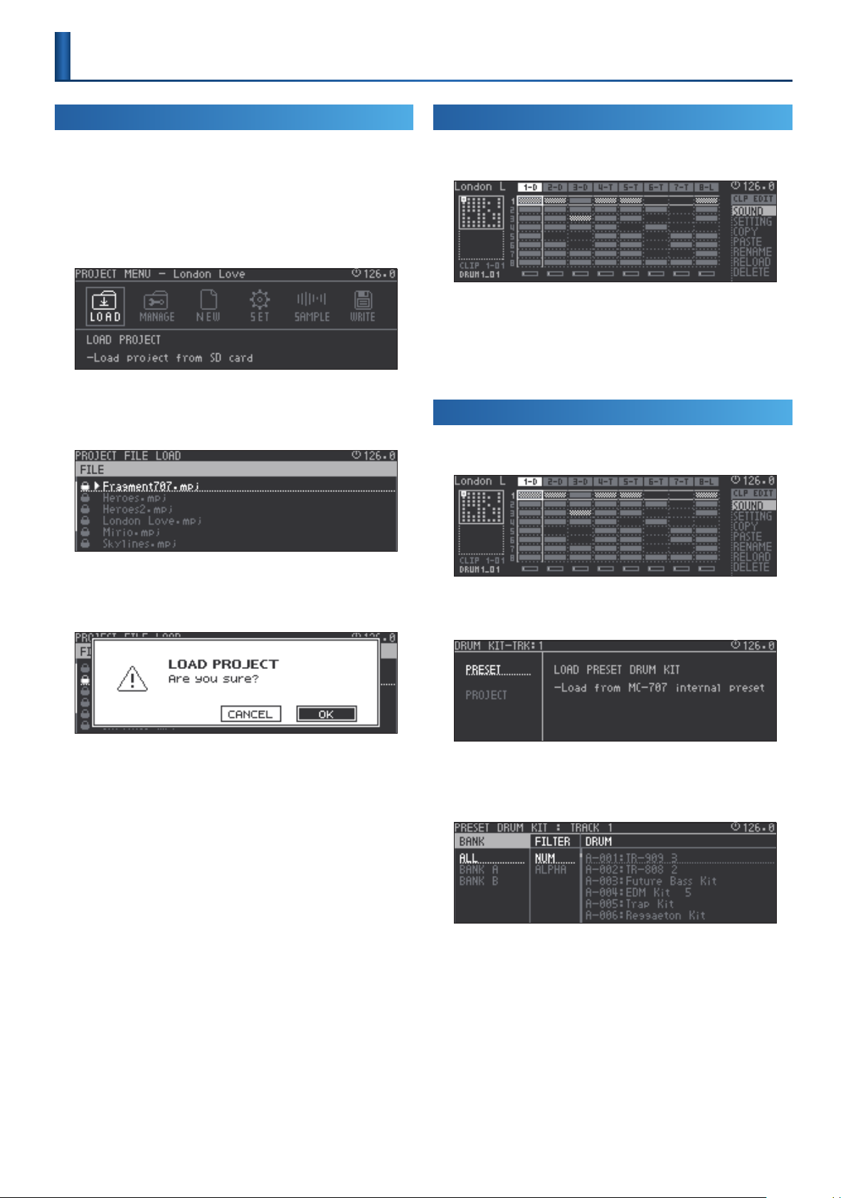
Loading and Playing a Project
On the MC-707, data for one song is managed as a unit called a
“project.”
Projects are saved on an SD card. A project contains tracks, clips, tone
data, and data for the samples that are used.
Press the [PROJECT] button.
1.
The PROJECT MENU screen appears.
Use the cursor buttons to select “LOAD,” and then press the
2.
[ENTER] button.
The PROJECT FILE LOAD screen appears.
Changing the Clips that Play
The HOME screen appears.
1.
Use the cursor buttons to select the clip that you want to
2.
play.
Press the [ENTER] button to reserve playback for the clip.
3.
Press the [START/STOP] button to start playback.
4.
Selecting a Tone or Drum Kit
Press the [SEL] button, and select a tone or drum kit track.
1.
Use the cursor buttons to select a project, and then press
3.
the [ENTER] button.
A conrmation message appears.
Use the cursor buttons to select “O K,” and then press the
4.
[ENTER] button.
The project is loaded from the SD card.
If you decide to cancel, use the cursor [<] [>] buttons to select
“CANCEL,” and then press the [ENTER] button.
* It might take some time for the project to be loaded.
* If the project has been edited, a conrmation message appears.
When loading is completed, you return to the home screen.
Press the [START/STOP] button.
5.
The project plays.
Press the [SOUND] button.
2.
The Sound browser appears.
Use the cursor buttons to select “PRESET,” and then press
3.
the [ENTER] button.
The PRESET browser appears.
Use the cursor buttons to select a sound.
4.
In the PRESET browser when the PAD MODE [NOTE] button is lit,
you can use the pads to audition the sound.
Press the [ENTER] button to conrm the sound.
5.
You return to the home screen.
11
Page 12
Basic Operation
Importing a Clip
Move the cursor to the position at which you want to import
1.
a clip.
Press the [CLIP] button.
2.
The clip browser shows the projects that are in the SD card.
When you use the cursor buttons to select a project, the
3.
clips inside it are shown.
* Clips of the same type as the track type of the currently selected track are
shown.
Use the cursor buttons to select the clip that you want to
4.
import, and then press the [ENTER] button.
The clip is imported.
Importing might take some time.
When importing is completed, you return to the home screen.
12
Page 13

Reference Section
Page 14
Main Screen
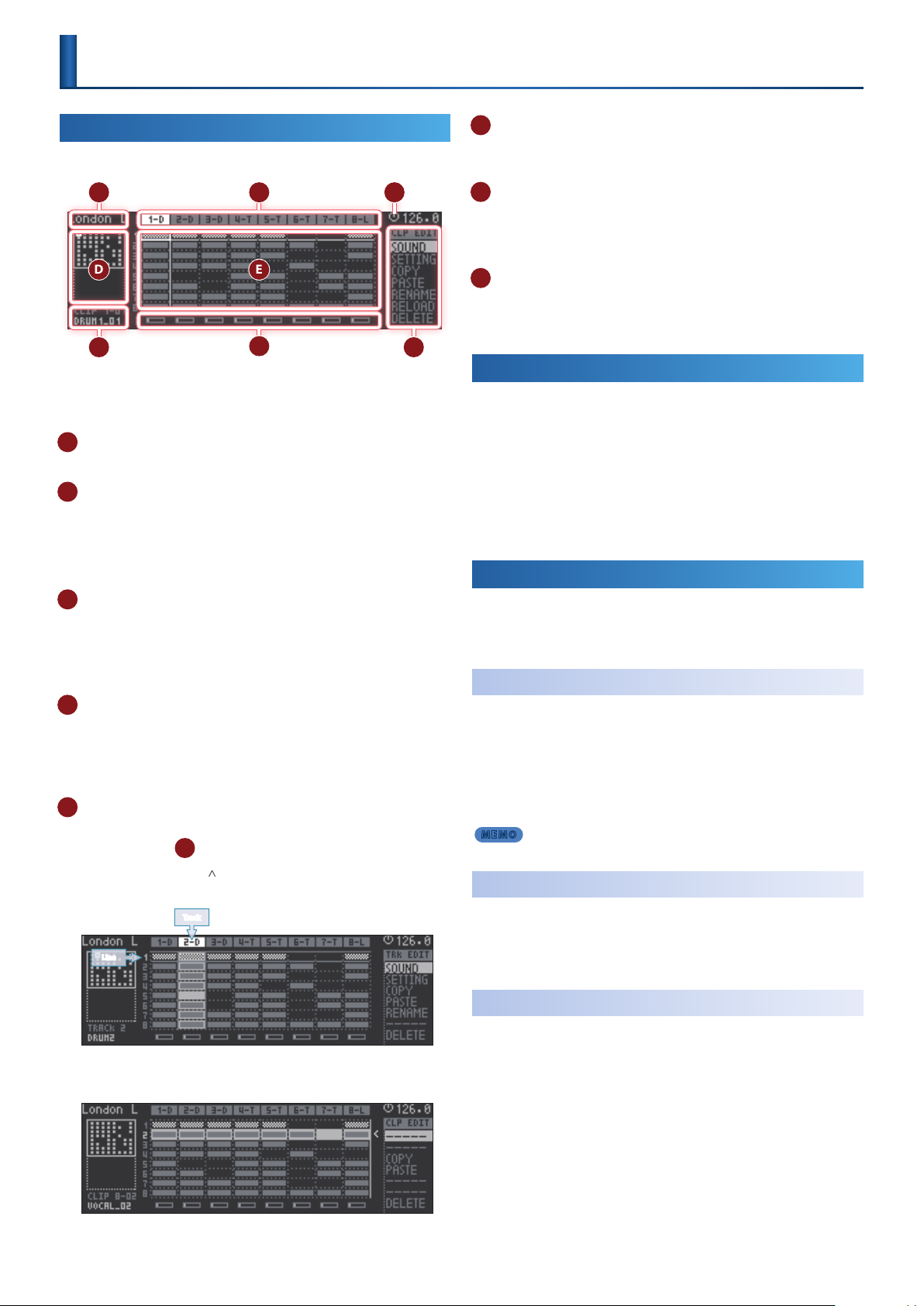
HOME Screen
When the MC-707 starts, the home screen appears.
A
F
In the home screen you can play and edit clips.
If something other than the home screen is shown, press the [EXIT]
button several times to access the home screen.
A Project name
Shows the project name.
B Track name (type)
Shows the track number and type.
T: TONE
D: DRUM
L: LOOPER
C Master clock icon
The MC-707 switches clips according to the timing of the master
clock (the circle in the upper right).
The tempo is shown at the right of the icon.
For details, refer to “Master Clock” (p. 52).
&
D Scroll bar
The MC-707 lets you register 16 clips in each track.
The clip screen shows up to eight clips, and you can switch this
display by using the [C1] knob to scroll.
* The scroll bar shows a miniature depiction of the clips.
E Clip view
Lists the clips. Use the cursor buttons to move the cursor. You can
H
use commands (
By pressing the cursor [
can select/edit a track.
Line
) to edit the selected item.
Track
B
E D
G
] button in the top line of the clip view, you
C
F Clip number, clip name
Shows the number of the current track, the clip number, and clip
name.
G Level meter
Shows the output volume of each track.
If a stop-reservation (stop at the next switch) occurs in a track, this
is shown with a mesh overlay.
H Command
This area shows the commands that can be executed to edit a clip
or a track.
“Editing a Track or Clip ([C4] Knob)” (p. 14)
H
&
Selecting a Clip
Use the cursor buttons to move the cursor to the clip that
1.
you want to play.
Press the [ENTER] button
2.
Reserves playback for the clip.
If the sequencer is playing, playback starts when the master clock
points to 12 o’clock.
Use the [START/STOP] button to play/stop.
Editing a Track or Clip
The track or clip that's selected in the clip view can be edited by the
command that's selected by the [C4] knob.
To execute the command, press the [C4] knob.
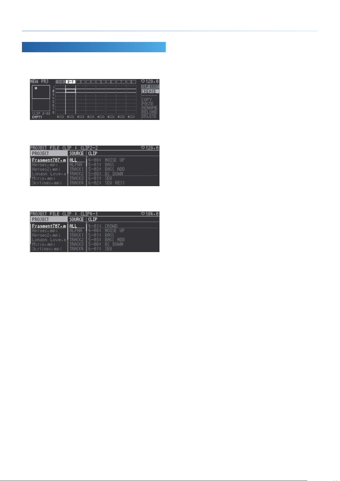
Creating a Clip
Select a vacant clip slot in a tone or drum track.
1.
The command indicates “CREATE.”
Use the [C4] knob to select “CREATE,” and then press the [C4]
2.
knob.
The clip is created.
MEMO
You can also create a clip by using the [REC] button to newly record it.
Editing the Sound
You can edit the settings of the sound (tone, drum, or looper sample)
that's used by the track or clip.
For details, refer to “Editing the TONE Track” (p. 41), “Editing
&
the DRUM Track” (p. 45), “LOOPER Track” (p. 48).
(CREATE)
([C4] Knob)
(SOUND)
By pressing the cursor [>] button at the far right of the clip view,
you can select and edit all clips of each line.
* The grid locations that accommodate clips are called “clip slots.”
14
Editing the Clip Settings
You can edit settings related to how the clip is played by the sequencer.
For details, refer to “Editing a Clip’s Settings” (p. 50).
&
(SETTING)
Page 15
Main Screen
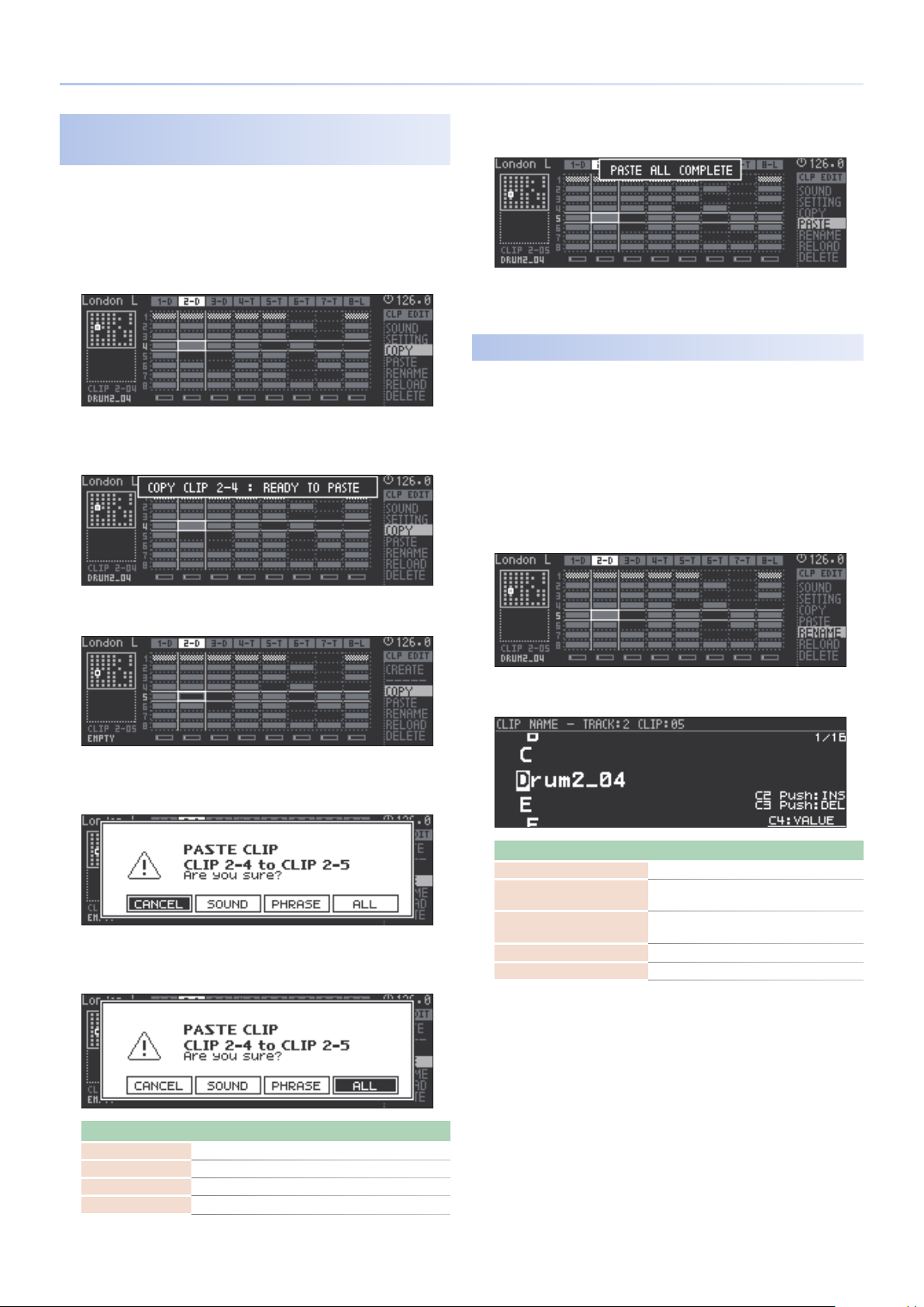
Copying the Sound or Phrase of a Clip
(COPY/PASTE)
Here’s how to duplicate the data of a clip or a sound.
You can make a complete duplicate of a clip, or you can duplicate
individual lines of a clip.
Use the cursor buttons to select the clip that you want to
1.
copy.
Use the [C4] knob to select “CO PY,” and then press the [C4]
2.
knob.
When the copy is completed, a message appears in the upper part
of the screen.
* You can’t overwrite a clip onto a looper clip. Delete the clip rst, and then copy.
* You can’t copy a looper clip if there is insucient memory. Either delete
unneeded looper clips or execute LOOPER OPTIMIZE (p. 55).
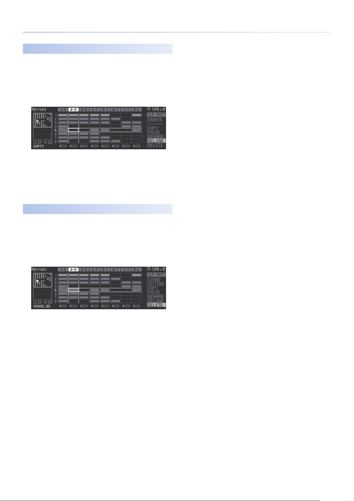
Renaming a Clip
Here’s how to edit the clip name that’s shown in the lower left of the
home screen.
If you want to use the clip in another project (when importing), this is
used as the clip name shown in the browser.
Use the cursor buttons to select the clip that you want to
1.
(RENAME)
rename.
Use the [C4] knob to select “RENAME,” and then press the
2.
[C4] knob.
Use the cursor buttons to select the copy-destination clip.
3.
Use the [C4] knob to select “PASTE,” and then press the [C4]
4.
knob.
Use cursor [<] [>] buttons to select the content that will be
5.
copied, and then press the [ENTER] button.
Edit the clip name.
3.
Operating the Unit Explanation
Cursor [<] [>] buttons Selects the character to edit.
[C2] knob
[C3] knob [C4] knob,
[VALUE] knob
Press the [C2] knob Inserts a space.
Press the [C3] knob Deletes a character.
To conrm the clip name, press the [ENTER] button.
4.
The clip name is changed.
If you decide to cancel, press the [EXIT] button.
Switches between uppercase, lowercase,
numerals, and symbols.
Change the character.
Operation Explanation
CANCEL Cancels the copy.
SOUND Copies only the sound.
PHRASE Copies only the phrase.
ALL Copies the sound and the phrase.
15
Page 16
Main Screen
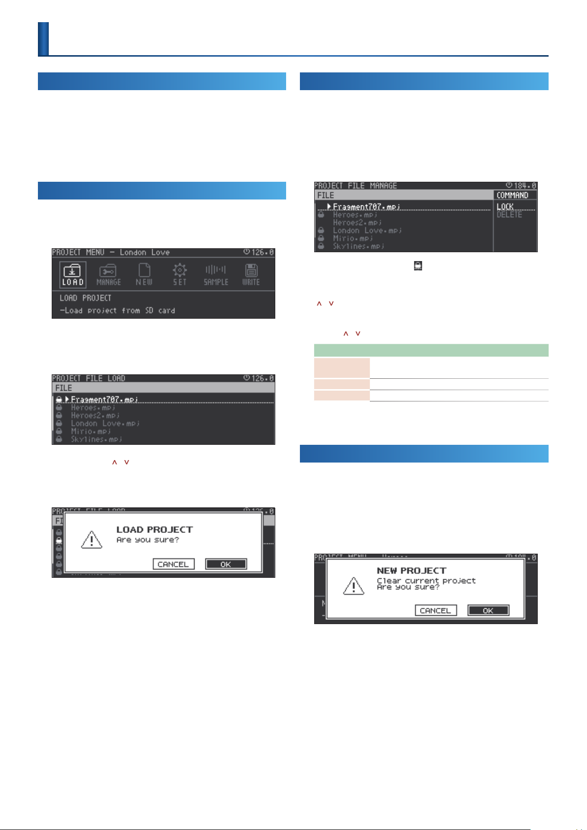
Reloading a Clip
Here’s how to recover the specied clip by loading it from the SD card.
Use the cursor buttons to select the clip that you want to
1.
reload.
Use the [C4] knob to select “RELOAD,” and then press the [C4]
2.
knob.
A conrmation message appears.
Use the cursor [<] [>] buttons to select “O K,” and then press
3.
the [ENTER] button.
The clip reverts to the state in which it was last saved in the project.
If you decide to cancel, use the cursor [<] [>] buttons to select
“CANCEL,” and then press the [ENTER] button.
Deleting
Here’s how to delete the selected clip.
(DELETE)
(RELOAD)
Use the cursor buttons to select the clip that you want to
1.
delete.
Use the [C4] knob to select “DELETE,” and then press the [C4]
2.
knob.
A conrmation message appears.
Use the cursor [<] [>] buttons to select “O K,” and then press
3.
the [ENTER] button.
The clip is deleted.
If you decide to cancel, use the cursor [<] [>] buttons to select
“CANCEL,” and then press the [ENTER] button.
16
Page 17
Project Operations
What Is a Project?
On the MC-707, data for one song is handled as a unit called a “project.”
Projects are saved on the SD card.
A project contains data for tracks, clips, tones, and the samples that are
used.
If you want to keep the results of editing, save the project.
For details, refer to “An Overview of the MC-707” (p. 9).
&
Loading a Project
Here’s how to load a project from the SD card.
Press the [PROJECT] button.
1.
Use the cursor [<] [>] buttons to select “LOAD,” and then
2.
press the [ENTER] button.
The PROJECT FILE LOAD screen appears.
Managing Projects
Here’s how to protect or delete project les on the SD card.
Press the [PROJECT] button.
1.
Use the cursor [<] [>] buttons to select “MANAGE,” and then
2.
press the [ENTER] button.
The PROJECT FILE MANAGE screen appears.
* Projects for which a lock symbol ( ) are shown are protected, and cannot be
overwritten or deleted.
Use the cursor [<] button to select “FILE,” and use the cursor
3.
] [ ] buttons to select a project le.
[
Use the cursor [>] button to select “COMMAND,” and use the
4.
cursor [
Command Explanation
LOCK
UNLOCK Unlocks the project le.
DELETE Deletes an unlocked project le.
] [ ] buttons to select a command.
Locks the project le.
Deletion or overwrite-saving will not be possible.
Use the cursor [ ] [ ] buttons to select a project le.
3.
Press the [ENTER] button.
4.
A conrmation message appears.
Use the cursor [<] [>] buttons to select “O K,” and then press
5.
the [ENTER] button.
The project is loaded.
If you decide to cancel, use the cursor [<] [>] buttons to select
“CANCEL,” and then press the [ENTER] button.
* If you had edited the project, a conrmation message appears.
* When you create a new project, any unsaved content of the currently-open
project is lost.
Press the [ENTER] button.
5.
Execute the selected command.
Creating a New Project
Here’s how to create a new project.
Press the [PROJECT] button.
1.
Use the cursor [<] [>] buttons to select “NEW,” and then
2.
press the [ENTER] button.
A conrmation message appears.
* If the project has been edited, a conrmation message appears.
* When you create a new project, any unsaved content of the currently-open
project is lost.
Use the cursor [<] [>] buttons to select “O K,” and then press
3.
the [ENTER] button.
If you decide to cancel, use the cursor [<] [>] buttons to select
“CANCEL,” and then press the [ENTER] button.
17
Page 18
Project Operations
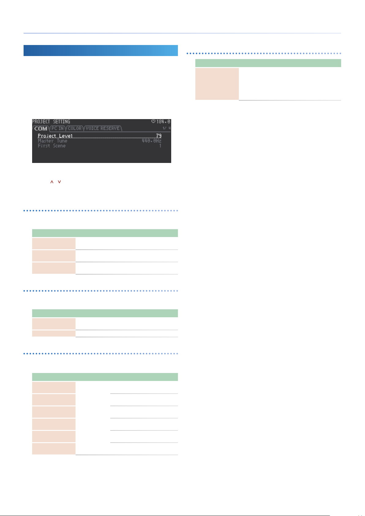
Making Project Settings
Here’s how to make settings such as the project’s volume and the pad
illumination colors.
Press the [PROJECT] button.
1.
Use the cursor [<] [>] buttons to select “ S ET,” and then press
2.
the [ENTER] button.
The PROJECT SETTING screen appears.
Use the cursor [<] [>] buttons to select a tab, and use the
3.
cursor [
Use the [C4] knob to edit the value.
4.
COM tab
Here you can specify the volume, the reference pitch, and the scene
that is recalled when the project is loaded.
Parameter Value Explanation
Project Level 0–127
Master Tune 415.3Hz–466.2Hz
First Scene 1–8
] [ ] buttons to select the parameter.
Species the volume of the overall
project.
Species the reference pitch for the
project.
Species the scene number that is
recalled when the project is loaded.
VOICE RESERVE tab
Parameter Value Explanation
TRACK 1–8 0–10
Species how polyphony resources are
allocated to each tone/drum track.
The track is given priority for the
specied number of voices.
* The number of voices used diers
depending on the sound.
PC IN tab
Here you can make settings for audio that is input from a USBconnected computer to the PC IN port.
Parameter Value Explanation
PC Level 0–255
PC Pan L128–127R Species the pan of the USB PC IN port.
Species the input level from the USB
PC IN port.
COLOR tab
Here you can specify the color of each pad mode.
For details, refer to “Pad Operations (PAD MODE)” (p. 22).
&
Parameter Value Explanation
PAD Note Color
PAD OCT Color
Play Clip Color
*1
Stay Clip Color
Stop Clip Color
Mute Pad Color
*1 ORANGE, YELLOW, GREEN, BLUE, PURPLE, PINK, WHITE, SKYBLUE, P.YELLOW,
P.BLUE, P.PINK, L.RED, L.ORANGE, L.YELLOW, L.GREEN, P.GREEN, L.SKYBLUE,
L.BLUE, L.PURPLE
Species the color of pads used for PAD
MODE NOTE performance.
Species the color of pads used for PAD
MODE NOTE octave.
Species the color of pads while a clip
is playing for PAD MODE CLIP.
Species the color of pads while a clip
is stopped for PAD MODE CLIP.
Species the color of pads that start/
stop a track for PAD MODE MUTE.
Species the color of pads that mute a
track for PAD MODE MUTE.
18
Page 19
Project Operations
Managing Samples Loaded into a Project
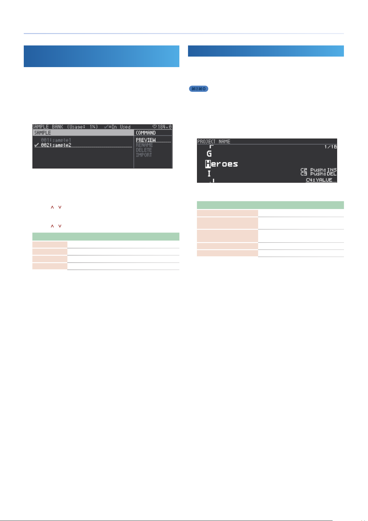
(Sample Bank)
Here’s how to manage the samples that are loaded into a project.
Press the [PROJECT] button.
1.
Use the cursor [<] [>] buttons to select “SAMPLE,” and then
2.
press the [ENTER] button.
The SAMPLE BANK screen appears.
* Even if you delete a clip or track, the samples used by the sound will remain.
* Samples with a check mark are used by sounds in the project.
* Samples without a check mark are not used by any sound.
Use the cursor [<] button to select “SAMPLE,” and use the
3.
cursor [
Use the cursor [>] button to select “COMMAND,” and use the
4.
cursor [
Command Explanation
PREVIEW Auditions the sound.
RENAME Renames the sample.
DELETE Deletes the sample.
IMPORT Imports a sample from the SD card.
Press the [ENTER] button.
5.
Execute the selected command.
] [ ] buttons to select a sample.
] [ ] buttons to select a command.
Saving a Project
Here’s how to save the project to the SD card.
Press the [PROJECT] button.
1.
MEMO
You can also save by holding down the [SHIFT] button and pressing
the [FUNC] button.
Use the Cursor [<] [>] buttons to select “WRITE,” and then
2.
press the [ENTER] button.
The PROJECT NAME screen appears.
Use the cursor buttons to edit the project name.
3.
Operating the Unit Explanation
Cursor [<] [>] buttons Selects the character to edit.
[C2] knob
[C3] knob [C4] knob,
[VALUE] knob
Press the [C2] knob Inserts a space.
Press the [C3] knob Deletes a character.
Press the [ENTER] button.
4.
A conrmation message appears.
Use the cursor [<] [>] buttons to select “O K,” and then press
5.
the [ENTER] button.
If you decide to cancel, use the cursor [<] [>] buttons to select
“CANCEL,” and then press the [ENTER] button.
* If there is a project of the same name, it is overwritten.
* Projects with a lock symbol are locked, and cannot be overwritten.
* If there is no project of the same name, the project is saved as a new project.
Switches between uppercase, lowercase,
numerals, and symbols.
Change the character.
19
Page 20
Track Operations
Creating a Track
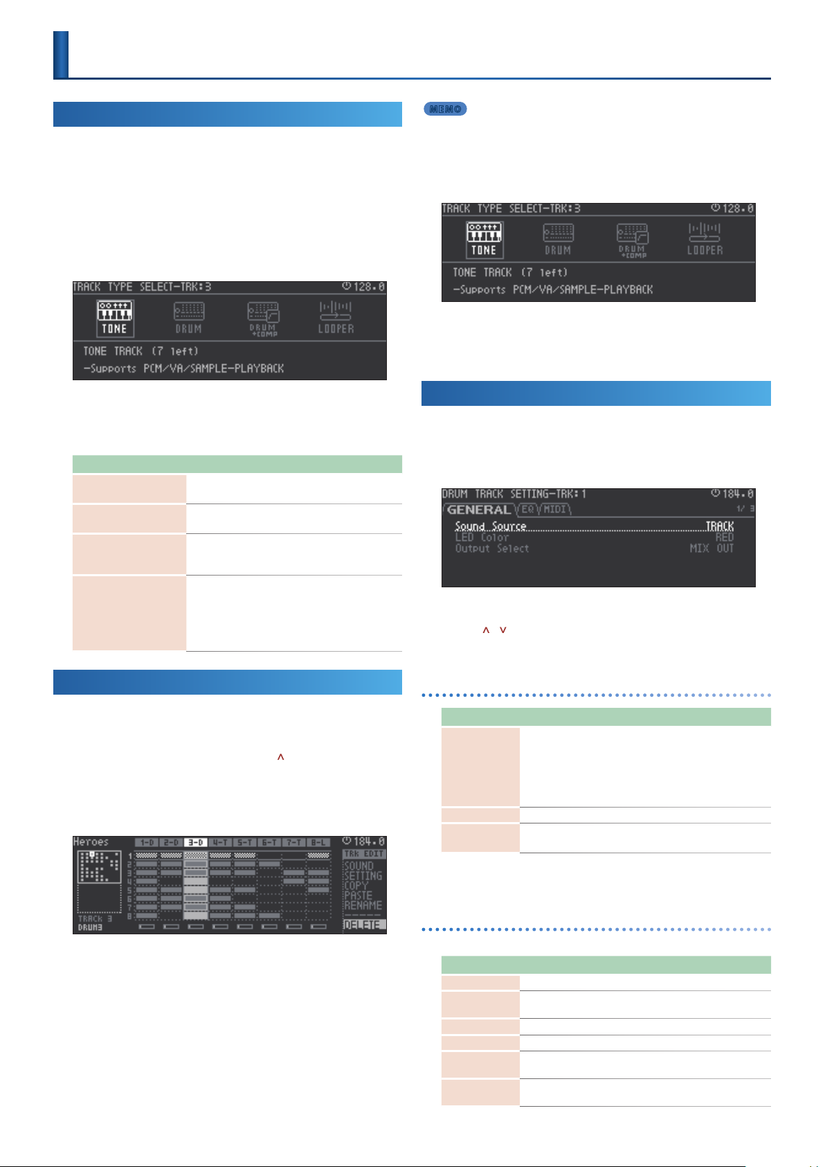
The MC-707 has four track types: TONE, DRUM, DRUM + COMP, and
LOOPER.
Up to eight track types can be freely combined in each track.
Depending on the track type, there is a maximum number that can be
used simultaneously.
Press the [SEL] button of an empty track.
1.
The TRACK TYPE SELECT screen appears.
Use the cursor [<] [>] buttons to select type, and then press
2.
the [ENTER] button.
The track is created, and you return to the home screen.
Track type Explanation
TONE
DRUM
DRUM + COMP
LOOPER
This is a synthesizer sound engine.
It can also be used as a pitched sampler.
This is a drum sound engine.
It can also be used as a sampler.
This is a drum sound engine with compressor (maximum
one track).
If this track is used, looper tracks are limited to ve.
This is a sampling looper that supports time stretch.
It supports loading samples from SD card, and recording
from an external input or a track. (A maximum of ve
looper tracks can be used if the project uses a DRUM +
COMP track; if not, a maximum of eight looper tracks
can be used.)
MEMO
You can also execute by pressing the [C4] knob once again.
With the track that you want to delete selected, press the
5.
[ENTER] button.
The TRACK TYPE SELECT screen appears.
Use the cursor [<] [>] buttons to select type, and then press
6.
the [ENTER] button.
The track is created, and you return to the home screen.
Making Track Settings
Hold down the [SHIFT] button and press the [SEL] button of
1.
the track for which you want to make settings.
The setting screen appears.
Use the cursor [<] [>] buttons to select a tab, and use the
2.
cursor [
Use the [C4] knob to edit the value.
3.
] [ ] buttons to select a parameter.
Changing a Track to a Dierent Type
To change the type of a track, delete the track and then create a new
track.
In the home screen, press the cursor [ ] button several
1.
times to select the entire track.
Use the cursor [<] [>] buttons to select the track that you
2.
want to change.
Turn the [C4] knob to select “DELETE,” and then press the
3.
[C4] knob.
A conrmation message appears.
Use the cursor [<] [>] buttons to select “O K,” and then press
4.
the [ENTER] button.
The track is deleted.
If you decide to cancel, use the cursor [<] [>] buttons to select
“CANCEL,” and then press the [ENTER] button.
GENERAL tab
Parameter Value Explanation
Species whether the track’s sound uses the
settings of the track or of the clip.
Sound Source
LED Color *1 Species the color shown for the level fader.
Output Select
ORANGE, YELLOW, GREEN, BLUE, PURPLE, PINK, WHITE, SKYBLUE, P.YELLOW,
*1
P.BLUE, P.PINK, L.RED, L.ORANGE, L.YELLOW, L.GREEN, P.GREEN, L.SKYBLUE, L.BLUE,
L.PURPLE
TRACK,
CLIP
MIX OUT,
ASSIGN OUT
* If this is TRACK, all sounds used in the same
track will be in common.
* If this is CLIP, dierent sounds can be used for
each clip.
* A looper track does not have this setting.
Species the output destination of
assignable out.
EQ tab
These are the track EQ settings.
Parameter Value Explanation
EQ Sw OFF, ON Turns the equalizer on/o.
EQ Input Gain -24–+24 [dB]
EQ Low Gain -24–+24 [dB] Gain of the low frequency range.
EQ Low Frequency 20–16000 [Hz] Frequency of the low range.
EQ Mid Gain -24–+24 [dB]
EQ Mid Frequency 20–16000 [Hz]
Adjusts the amount of boost/cut at the input
to the EQ.
Adjusts the amount of boost/cut for the mid
frequency range.
Species the center frequency of the mid
frequency range.
20
Page 21

Parameter Value Explanation
Species the width of the mid frequency
EQ Mid Q 0.5–16.0
EQ High Gain -24–+24 [dB] Gain of the high frequency range.
EQ High Frequency 20–16000 [Hz] Frequency of the high range.
range.
Set a higher value for Q to narrow the range
to be aected.
MIDI tab
Here you can switch on/o the output of MIDI messages from the
sequencer to each port.
Parameter Value Explanation
TX MIDI OUT1 OFF, ON
TX MIDI OUT2 OFF, ON
Tx USB MIDI OFF, ON Enables output to the rear panel USB port.
Enables output to the rear panel MIDI OUT 1
connector.
Enables output to the rear panel MIDI OUT 2
connector.
Track Operations
21
Page 22
Pad Operations
(PAD MODE)
Using Mute Mode
This lets you use the pads to mute tracks or stop/play clips.
Press the [MUTE] button.
1.
Operation switches to Mute mode.
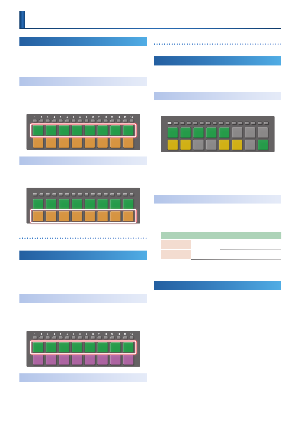
Stopping/Playing Tracks
Press a pad [1]–[8].
1.
You can reserve play/stop independently for each track.
* Play and stop occur at the timing of the master clock.
1 92 103 114 125 136 147 158 16
Muting a Track
Press a pad [9]–[16].
1.
The track is muted. Press the pad once again to unmute.
1 92 103 114 125 136 147 158 16
(Pads [9]–[16])
(Pads [1]–[8])
Changing a pad’s color
“Making Project Settings” (p. 18)
&
Using Clip Mode
When you press the PAD MODE button CLIP, the pads switch to Clip
mode.
This mode lets you use the pads to play/stop clips.
Switching Clips
Of the 16 lines in track, the pads show two adjacent lines. You can use
the [1]–[16] buttons to switch the lines that are shown.
1 92 103 114 125 136 147 158 16
Press the PAD MODE [CLIP] button.
1.
The pads are in Clip mode.
You can select the clips that are played by the pads.
Press the pads to select clips.
2.
The clips are switched.
Changing a pad’s color
“Making Project Settings” (p. 18)
&
Using Cue Mode
This lets you use the pads to audition the playback content of a pad via
your headphones (PHONES), or to stop/play clips.
Hold down the [SHIFT] button and press the [MUTE] button.
1.
Operation switches to Cue mode.
Stopping/Playing Tracks
Press a pad [1]–[8].
1.
You can reserve play/stop independently for each track.
* Play and stop occur at the timing of the master clock.
1 92 103 114 125 136 147 158 16
(Pads [1]–[8])
Making Clip Mode Settings
Here’s how to change the pad illumination color for Clip mode.
Hold down the [SHIFT] button and press the [CLIP] button.
1.
The CLIP MODE SETTING screen appears.
Parameter Value Explanation
PLAY
*1
STOP
*1 ORANGE, YELLOW, GREEN, BLUE, PURPLE, PINK, WHITE, SKYBLUE, P.YELLOW,
P.BLUE, P.PINK, L.RED, L.ORANGE, L.YELLOW, L.GREEN, P.GREEN, L.SKYBLUE,
L.BLUE, L.PURPLE
Species the color of pads whose clip is
playing.
Species the color of pads whose clip is
playing.
Using Note Mode
This lets you perform or create phrases.
For details on how to create phrases, refer to the section that explains
creating musical phrases and motions.
Press the [NOTE] button.
1.
The pads switch to Note mode.
Using the Cue Function
Press a pad [9]–[16].
1.
The track is specied for cue. Press the pad once again to clear.
(Pads [9]–[16])
22
Page 23
Pad Operations (PAD MODE)
Playing
TONE track
For a TONE track, you can play the pads as a keyboard.
1 92 103 114 125 136 147 158 16
OCT- OC T+
C#
C
D
REST
D#
E
F#
TIE
G
F C
G#
A#
A
B
[OCT-] [OCT+]: Shift octaves.
[REST/TIE]: Use to create phrases.
For details, refer to “Step-Recording a Phrase” (p. 28).
&
DRUM track
For a DRUM track, you can use the pads to play the drum kit, or use the
pads with TR-REC to create phrases.
In a drum kit, 16 instruments are assigned to the pads, one instrument
to each pad.
By pressing the pads, you can switch the pad that you’re editing.
For details, refer to “Editing the DRUM Track” (p. 45).
&
MEMO
By holding down the [NOTE] button and pressing a pad, you can switch pads
without sounding a note.
LOOPER track
For a LOOPER track, you can use the pads to change the pitch of the
sample that’s played.
You can use the [OCT-] [OCT+] buttons to shift the pitch in a range of
-2–+2 octaves.
DRUM PAD MUTE
For a DRUM track, you can mute individual pads.
Hold down the [MUTE] button and press the pad.
1.
That pad’s clip is muted.
MEMO
You can combine this with a copy of the clip, and use it as a convenient function
for creating a variation of the drum kit.
TR-REC tab
Parameter Value Explanation
Species the velocity when using TR-REC to
VELOCITY 1–127
input a drum track.
1–127
COLOR tab
Parameter Value Explanation
PAD
OCTAVE
ORANGE, YELLOW, GREEN, BLUE, PURPLE, PINK, WHITE, SKYBLUE, P.YELLOW,
*1
P.BLUE, P.PINK, L.RED, L.ORANGE, L.YELLOW, L.GREEN, P.GREEN, L.SKYBLUE, L.BLUE,
L.PURPLE
*1
Specify the color of the pads used for
performance (PAD) and for octave (OCTAVE).
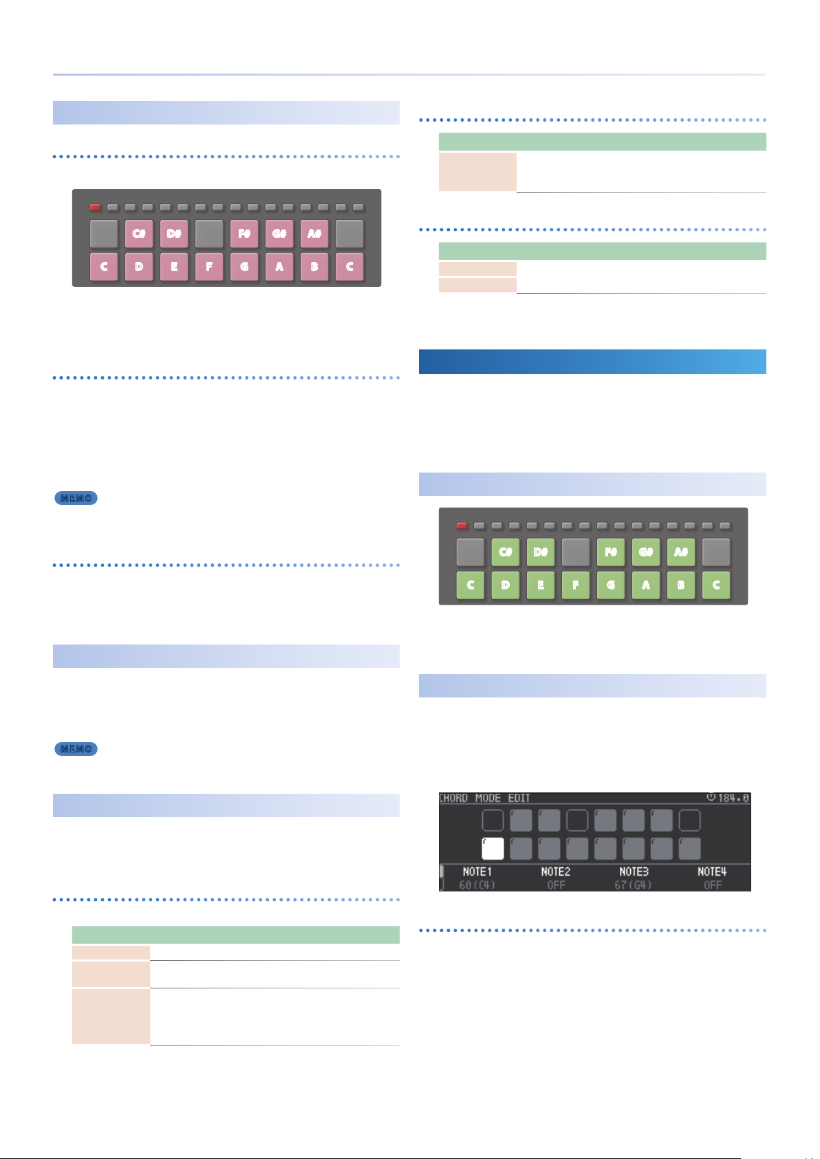
Using Chord Mode
You can assign chords to the pads and play them.
* Chord mode is used for a TONE track.
In a TONE track, press the [CHORD] button.
1.
The pads switch to Chord mode.
Playing
1 92 103 114 125 136 147 158 16
OCT- OC T+
C#
C
D
[OCT-] [OCT+]: Shift the octave.
[REST/TIE]: Used to enter a musical phrase.
For details, refer to “Step-Recording a Phrase” (p. 28).
&
Editing a Chord
Hold down the [SHIFT] button and press the [CHORD]
1.
button.
The CHORD MODE EDIT screen appears.
Here you can specify the chord.
REST
D#
E
F#
TIE
G
F C
G#
A#
A
B
Making Note Mode Settings
Hold down the [SHIFT] button and press the [NOTE] button.
1.
The NOTE MODE SETTING screen appears.
PAD tab
These are settings related to pad performance.
Parameter Value Explanation
OCTAVE -5–+5 Species the octave for pad performance.
TRANSPOSE -6–+6
LINEAR,
PAD VELO
EXP,
LOG,
FIX10–127
Species the key transpose for pad
performance.
Species the velocity sensitivity of the pads.
You can also specify a xed value.
Selecting a pad
Use the cursor buttons to move.
Alternatively, strike a pad to specify it.
23
Page 24
Pad Operations (PAD MODE)
Specifying a chord
Use the [C1]–[C4] knobs to edit the value.
1.
Turning a knob: 1 (C-1)–127 (G9)
Pressing a knob: Switches on/o
* To switch between parameter edit pages, press the [FUNC] button.
Parameter Value Explanation
NOTE1–4
COLOR *1 Species the pad color.
ORANGE, YELLOW, GREEN, BLUE, PURPLE, PINK, WHITE, SKYBLUE, P.YELLOW,
*1
P.BLUE, P.PINK, L.RED, L.ORANGE, L.YELLOW, L.GREEN, P.GREEN, L.SKYBLUE, L.BLUE,
L.PURPLE
OFF,
1 (C-1) –127 (G9)
Specify the notes in the chord.
Copying the selected chord
Hold down the [FUNC] button and press the cursor [ ]
1.
button.
This species the chord copy-source.
Hold down the [FUNC] button and press the cursor [ ]
2.
button.
The chord is pasted.
Scatter Mode
Using the [SCATTER] Button to Apply the
Eect
While in Scatter mode, press the [SCATTER] button.
1.
Step mode is selected.
While you hold down the [SCATTER] button, the eects specied
for the steps are applied consecutively, starting from the rst
(momentary mode).
You can also make the eect continue even after you release the
button (alternate mode).
For details, refer to “SCATTER” (p. 38).
&
Recording Eects in Steps
Hold down a step [1]–[16] button and press a pad [1]–[16].
1.
The eect of the specied pad is assigned to the specied step.
In addition to assigning pads to steps, you can also assign each step
its own eect.
For details, refer to “SCATTER” (p. 38).
&
Making Scatter Settings
Hold down the [SHIFT] button and press the [SCATTER]
1.
button.
You can use the pads to apply Scatter, and edit the eect.
Press the [SCATTER] button.
1.
Scatter mode is selected.
Using the Pads to Apply the Eect
Press a pad.
1.
The eect is applied while you hold down the pad.
The eect diers for each pad.
When you take your hand o the pad, it returns to the previous
state.
For details, refer to “SCATTER” (p. 38).
&
24
Page 25
Importing Clips
The clip browser lets you import clips from a project saved on the SD
card.
In the home screen, use the cursor buttons to select the clip
1.
slot into which you want to import a clip.
Press the [CLIP] button.
2.
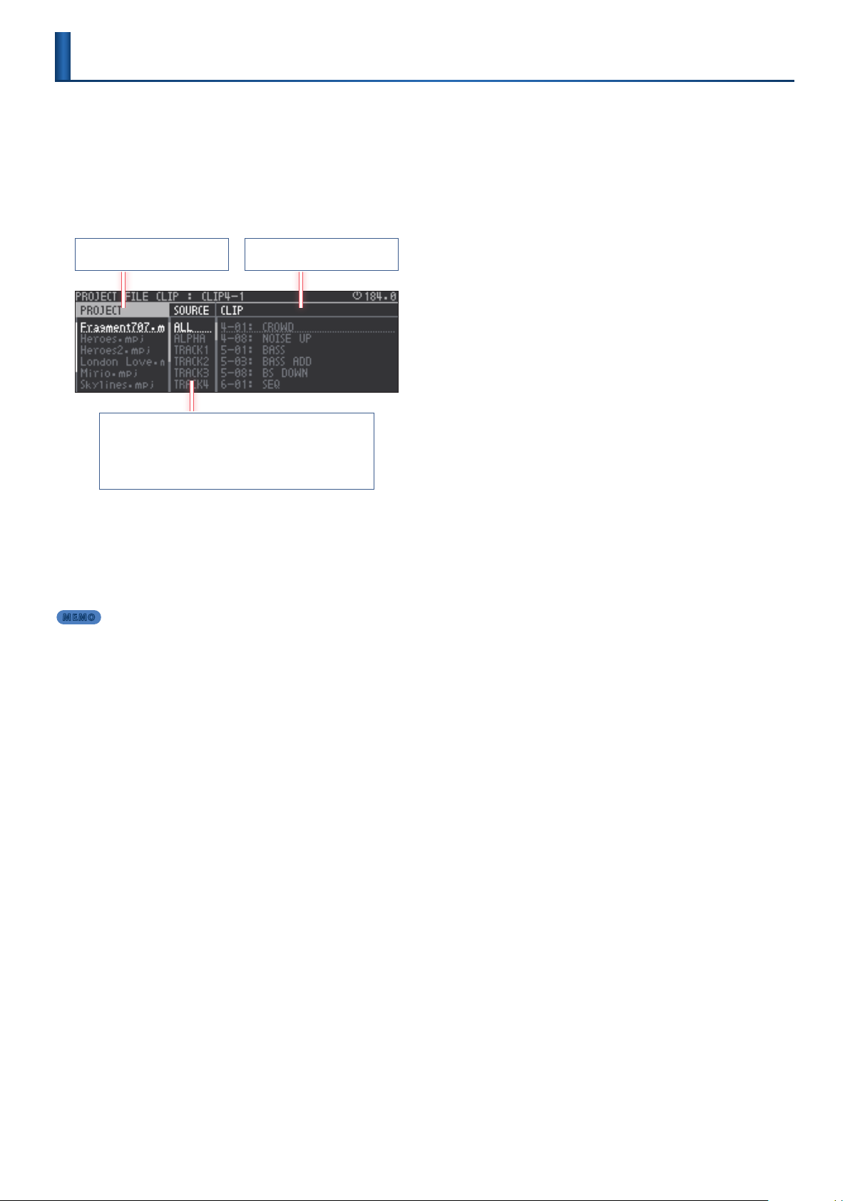
The PROJECT FILE CLIP screen (clip browser) appears.
(Clip Browser)
Shows the projects.
Sorts or lters the clips in the column at right.
ALL: Show all.
ALPHA: Sort in alphabetical order.
TRACK 1–8: Filter by track.
Select a clip.
3.
Use the cursor buttons to move between items (PROJECT, SOURCE,
CLIP).
Press the [ENTER] button.
4.
The clip is imported, and you return to the home screen.
MEMO
You can’t import a clip of a dierent track type.
5
If you want to use the sound of the import-source clip in a tone or drum track,
5
specify the track mode as Clip.
For details, refer to “Making Track Settings” (p. 25).
&
Shows the clips.
25
Page 26
Selecting Sounds
(Sound Browser)
The sound browser lets you load sounds or sample les into a project.
Loading a Preset Sound
Here’s how internal sounds of the MC-707 unit can be loaded into a
project.
Use the [SEL] buttons to select the track whose sound you
1.
want to change.
If you’re in Clip mode, select a clip.
Press the [SOUND] button.
2.
The menu screen appears.
Use the cursor buttons to select "PRESET," and then press
3.
the [ENTER] button.
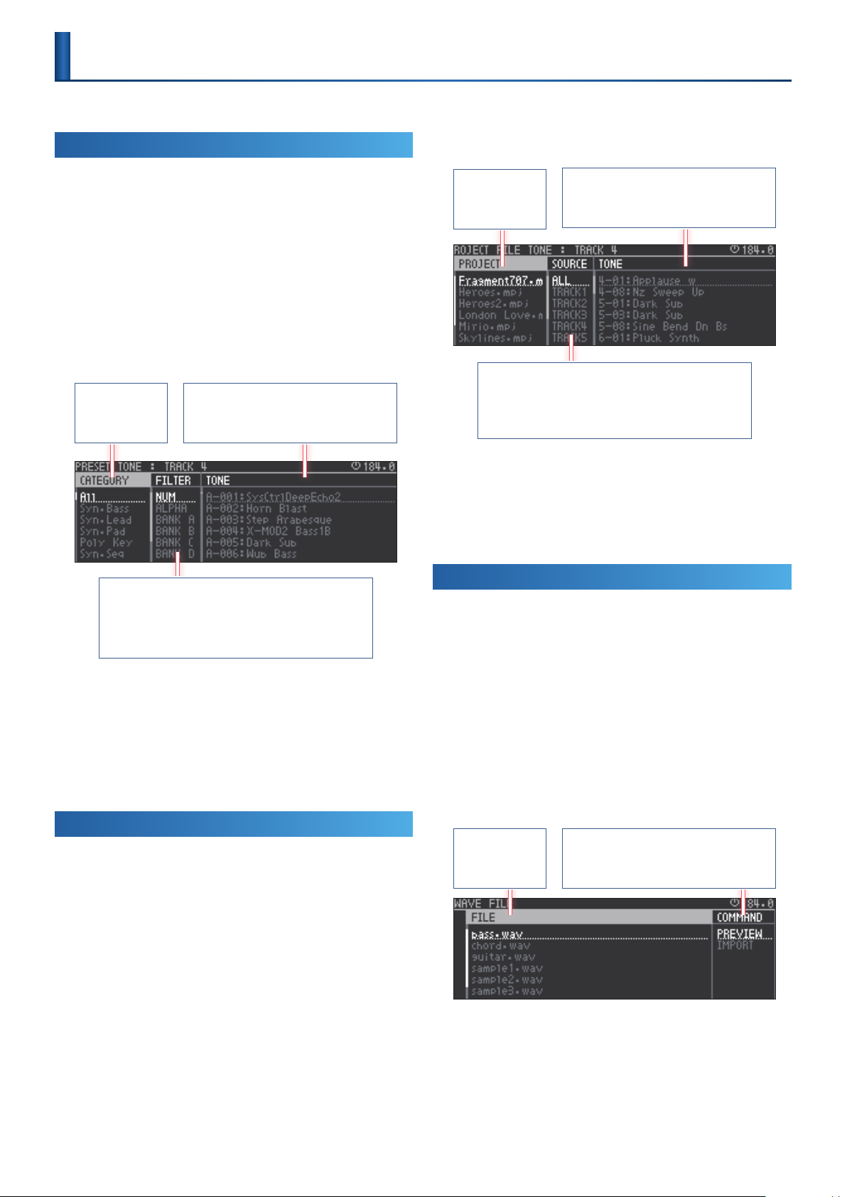
Now you can use the sound browser.
Shows the sound
categories.
Shows a list of sounds.
If you move the cursor to a sound, you can use the
pads to audition that sound.
Use the cursor buttons to select "PROJECT," and then press
3.
the [ENTER] button.
Now you can use the sound browser.
Shows the projects.
Sorts or lters the clips in the right column.
ALL : Show all.
TRACK 1–8: Show only the selected track of the project.
Use the cursor buttons to select a sound.
4.
Use the cursor [<] [>] buttons to move to an item (PROJECT,
SOURCE, TONE/DRUM/LOOP).
Press the [ENTER] button.
5.
The sound is imported, and you return to the home screen.
Lists the sounds/samples.
When you press the [ENTER] button to select a
sound/sample, it is imported.
Sorts or lters the sounds.
NUM: Sort in number order.
ALPHA: Sort in alphabetical order.
BANK A–F: Filter by bank.
Select a sound.
4.
Use the cursor buttons to move to an item (CATEGORY/BANK,
FILTER, TONE/DRUM).
Press the [ENTER] button.
5.
The sound is imported, and you return to the home screen.
* If SOUND SOURCE is Clip mode, the selecting clip must be the currentry-
playing clip in order for it to be auditioned.
Loading from a Project on the SD Card
Here's how to load a sound (tone, drum, instrument) or sample (looper)
from a project that's saved on the SD card.
Use the [SEL] buttons to select the track whose sound you
1.
want to change.
If you're in Clip mode, select a clip.
Press the [SOUND] button.
2.
The menu screen appears.
Loading Samples from the SD Card
Here’s how you can load samples that are saved on the SD card.
* Samples that you want to load must be placed in the ROLAND/GROOVEBOX/
SAMPLE folder of the SD card.
Use the [SEL] buttons to select the track into which you
1.
want to load the sample.
If you’re in Clip mode, select a clip.
Press the [SOUND] button.
2.
The menu screen appears.
Use the cursor buttons to select “WAVE FILE,” and press the
3.
[ENTER] button.
Now you can use the sound browser.
Shows the samples
that are saved on
the SD card.
PREVIEW: Previews the sample.
IMPORT: Imports the sample.
26
Use the cursor buttons to select a sample.
4.
Use the cursor [<] [>] buttons to move to an item (FILE,
COMMAND).
Press the [ENTER] button.
5.
The content shown in COMMAND is executed.
Page 27

The content that can be loaded depends on the track type
Selecting Sounds (Sound Browser)
Loading a preset sound
Loading a sound from a project
on the SD card (PROJECT)
Loading a sample from a
project on the SD card (PROJECT)
Loading a sample le from the
SD card (WAVE FILE)
(PRESET)
TONE
track
DRUM
track
DRUM
(kit)
track
(INST)
( ( (
( ( (
( ( (
LOOPER
track
(
27
Page 28
Step-Recording a Phrase
When the pads are in Note mode, you can use the step buttons and the
pads to step-record phrases.
You’ll create a pattern by specifying the steps at which each pad will
sound.
Tone Track
Press the PAD MODE [NOTE] button.
1.
The pads are in Note mode.
Use the step buttons to select the step that you want to
2.
input.
That step is selected for editing, and the step button blinks.
* The currently displayed measures are indicated by the MEASURE LEDs in the
lower left.
You can use the MEASURE [<] [>] buttons to move between
measures.
Press pads (keys) to enter notes.
3.
The pad that you input is lit.
If the EDIT screen is also displayed, the screen shows the notes that
are input.
Repeat steps 2–3.
4.
Press the [EXIT] button when you’re nished editing.
5.
You can also stop editing by pressing the currently-selected step
button once again.
Quick Input
Press the PAD MODE [NOTE] button.
1.
The pads are in Note mode.
Hold down the button of the step that you want to input,
2.
and press a pad (key) to input a note.
Inputting a Long Note
Press the PAD MODE [NOTE] button.
1.
The pads are in Note mode.
Use the step buttons to select the step that you want to
2.
input.
That step is selected for editing, and the step button blinks.
Hold down a pad (key) and press the pad [REST/TIE] button.
3.
A tie is input for the specied pitch.
(Inputting a Tie)
Changing the Measure Settings
Hold down the [SHIFT] button and press the MEASURE [<] [>]
1.
button.
The MEASURE EDIT screen appears.
In the MEASURE EDIT screen, you can make settings for the clip’s
notes.
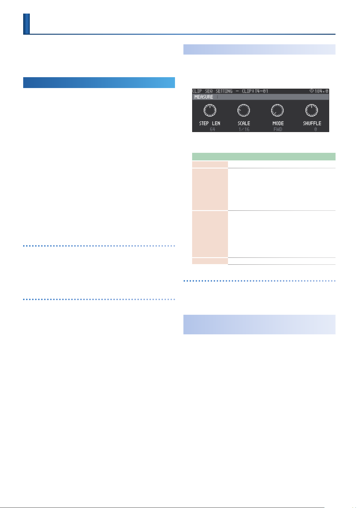
Parameter Value Explanation
STEP LEN 1–128 Species the length of the clip.
Species the resolution of the clip.
1/8: eighth notes
SCALE
MODE
SHUFFLE -50–+50 Species the amount of shue (bounce).
Duplicating a Measure
Hold down the [FUNC] button and press the MEASURE [>]
1.
1/8, 1/16, 1/32,
1/4T, 1/8T, 1/16T
FWD,
RE V,
FWD+REV,
INV,
RND
(Duplicate)
1/16: sixteenth notes
1/32: thirty-second notes
1/4T: quarter note triplets
1/8T: eight note triplets
1/16T: sixteenth note triplets
Species how the clip will play back.
FWD: Play forward from the rst step.
REV: Play in reverse from the last step.
FWD+REV: Play forward from the rst step,
then play backward from the last step.
INV: Play even-numbered and odd-
numbered notes inverted.
RND: Play randomly.
button.
The current measure is duplicated.
Automatically Advancing the Step During
Input
Step input mode automatically advances to the next step each time
you press and release a pad. This is a convenient way to quickly enter
an arpeggio pattern.
1.
2.
* By pressing the [REST/TIE] button you can advance the step without inputting
(Step Input Mode)
Hold down the [REC] button and press the step button.
You’re in step input mode.
Press a pad (key) to input a note.
When you release the pad, the step advances.
a step.
28
Page 29
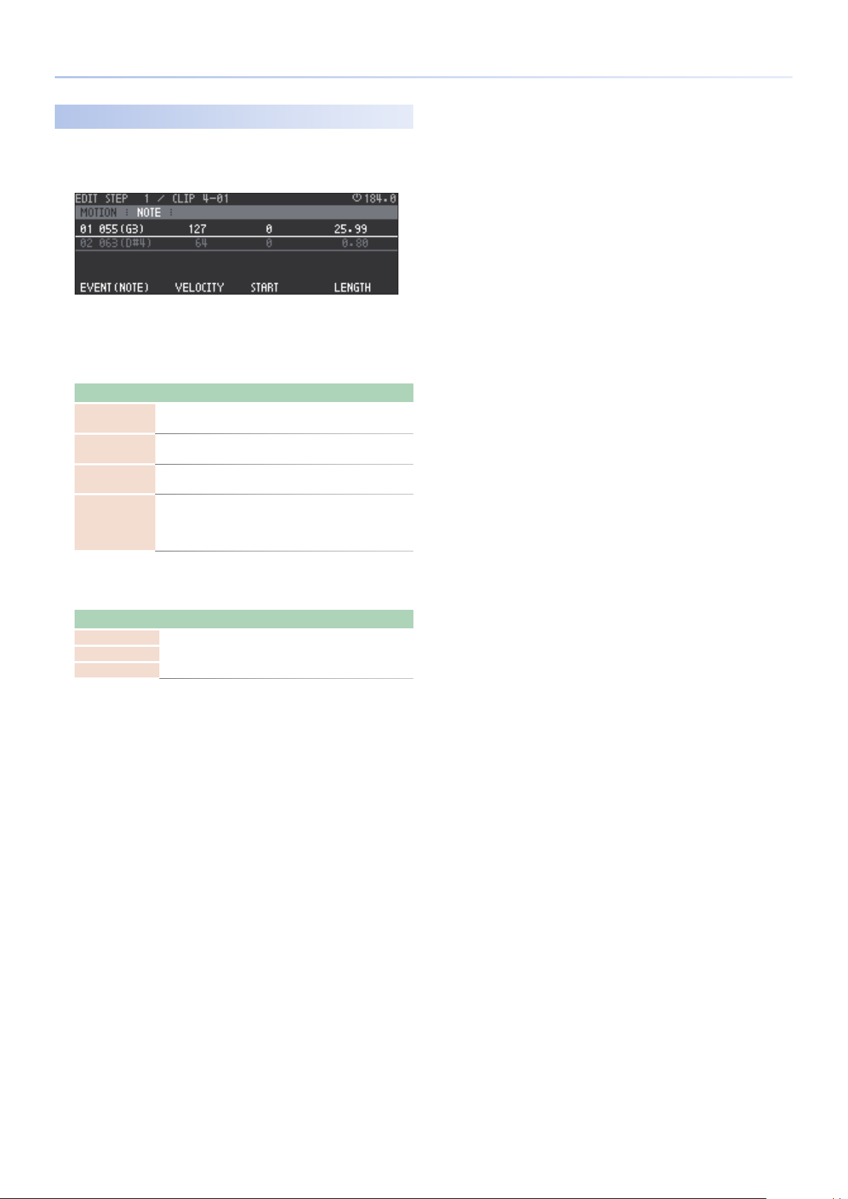
Editing the Notes of Each Step
Hold down the [SHIFT] button and press the step button.
1.
The STEP EDIT screen appears.
The notes of the selected step are shown.
Use the cursor to select the note that you want to edit.
2.
NOTE tab
Knob Explanation
[C1] knob
[C2] knob
[C3] knob
[C4] knob
EVENT (NOTE)
Species the note.
VELOCITY
Adjusts the velocity.
START
Adjusts the start timing of the note.
LENGTH
Species the length of the note.
If the same note exists at the distance to which the note was
extended, it cannot be extended further.
Step-Recording a Phrase
MOTION tab
Here you can make settings related to Motion.
Parameter Value Explanation
FILTER
OFF, 0–127 Adjust the motion value for each knob.MOD
FX
For details, refer to “Recording Knob Movement in Steps
&
(MOTION)” (p. 34).
29
Page 30
Step-Recording a Phrase
Drum Track: TR-REC
Press the PAD MODE [NOTE] button.
1.
The pad mode is set to Note mode.
Press a pad (key) to select the pad that you want to edit.
2.
The selected pad is lit, and now you can use the step buttons to
edit the notes of the selected pad.
Press the step buttons for the steps at which you want to
3.
input notes.
Notes are input.
If the EDIT screen is also shown, the screen shows the notes that
you input.
Repeat steps 2–3.
4.
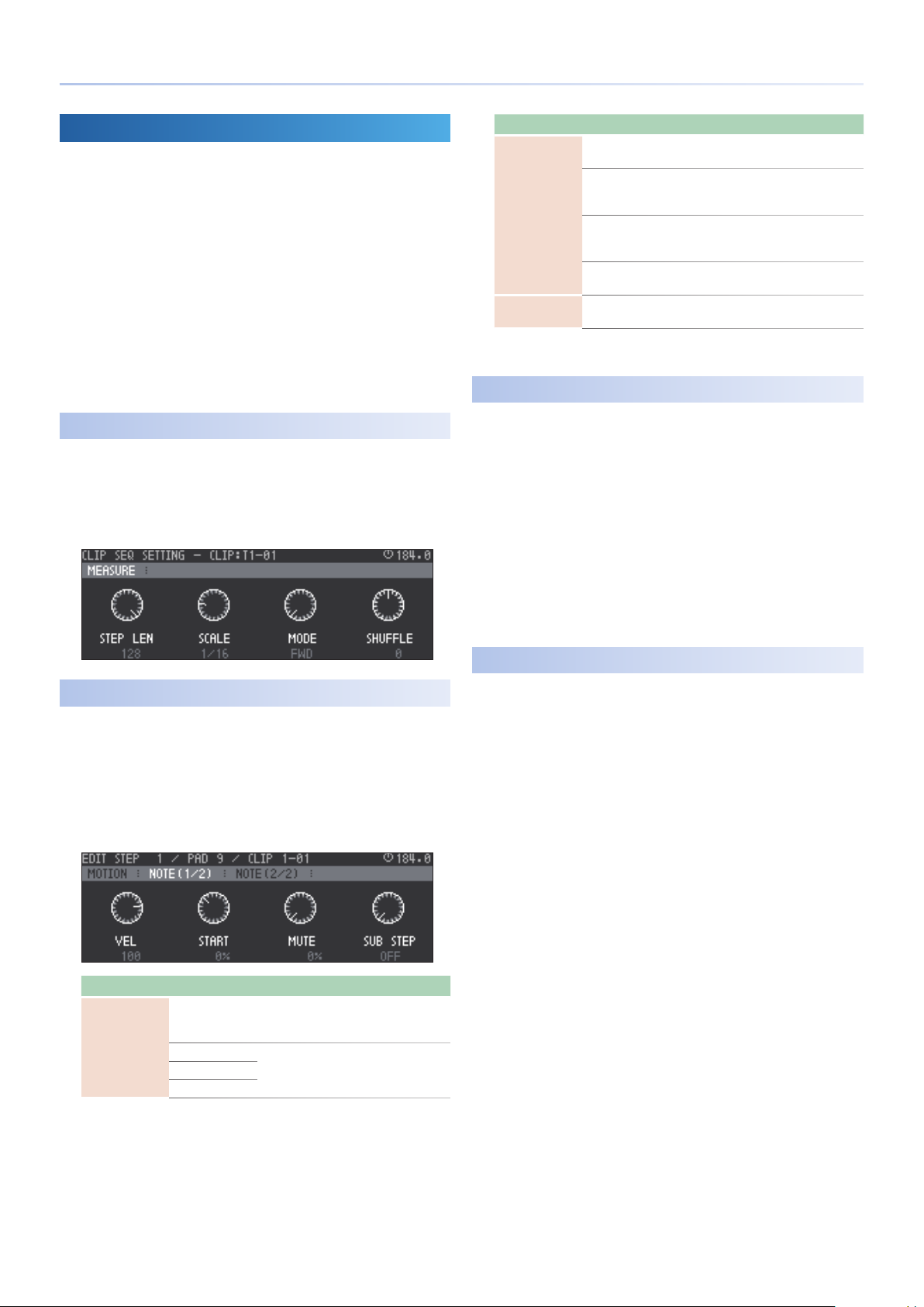
Increasing the Measures
Here you can make settings for the notes of the clip.
Hold down the [SHIFT] button and press the MEASURE [<] [>]
1.
buttons.
The CLIP SEQ SETTING: MEASURE screen appears.
Tab Parameter Explanation/Controller
VEL
START
NOTE (1/2) tab
MUTE
SUB STEP
NOTE (2/2) tab END
* By holding down the [CLEAR] button and pressing the currently-selected step
button, you can delete a note.
Adjusts the velocity.
[C1] knob
Adjusts the timing at which the start note
begins.
[C2] knob
Adjusts the probability that a mute note will
sound.
[C3] knob
Species a sub step.
[C4] knob
Species the end timing of the end note.
[C1] knob
Track Pad Mute
Here’s how to specify drum pad muting for each track.
This function is useful during a live performance when you want to add
development to your song by inserting and removing pads.
While holding down the [SEL] button of a drum track, press
1.
the pad that you want to mute.
The pad you specied is muted.
This setting applies to the track, and is maintained even if you
change clips.
Once again, hold down the [SEL] button and press the pad.
2.
Muting is cleared.
* This is also available if the pads are set to something other than Note mode.
Editing the Steps
Press a pad to select the pad that you want to edit.
1.
Hold down the [SHIFT] button and press a step button.
2.
The EDIT STEP screen appears.
Use the cursor buttons to switch tabs, and use the [C1]–[C4]
3.
knobs to edit the parameters.
Tab Parameter Explanation/Controller
Here you can make settings related to Motion.
For details, refer to “Recording Knob Movement in Steps
&
MOTION tab
(MOTION)” (p. 34).
FILTER
MOD
FX
Adjust the motion value of each knob.
OFF, 0–127
Clip Pad Mute
Here’s how to specify drum pad muting for each clip.
By inserting or removing parts, you can create additional variations of a
drum pattern.
Press the PAD MODE [NOTE] button.
1.
The pads are in Note mode.
While holding down the [MUTE] button, press the pad that
2.
you want to mute.
The specied pad is muted.
30
Page 31

Specifying the Last Step and First Step
Specifying the Last Step
By specifying the Last Step, you can make a mid-way step play as the
last step.
Press the PAD MODE [NOTE] button.
1.
The pads are in Note mode.
Hold down the [SHIFT] button and press the MOTION [REC]
2.
button.
Step Setting mode is selected.
Press the step button that you want to specify as the Last
3.
Step.
The Last Step is specied, and the playback region is lit green.
If you press the same step button once again, the setting is
cancelled.
Press the MOTION [REC] button.
4.
You exit Step Setting mode.
Step-Recording a Phrase
Specifying the First Step
By specifying the First Step, you can make a mid-way step play as the
rst step.
Press the PAD MODE [NOTE] button.
1.
The pads are in Note mode.
Hold down the [SHIFT] button and press the MOTION [REC]
2.
button.
Step Setting mode is selected.
Hold down the [SHIFT] button, and press the step button
3.
that you want to specify as the First Step.
The First Step is specied; the First Step is lit orange, and the
playback region is lit green.
To cancel the setting, once again hold down the [SHIFT] button and
press the same step button.
Press the MOTION [REC] button.
4.
You exit Step Setting mode.
Deleting the First Step and Last Step
Press the PAD MODE [NOTE] button.
1.
The pads are in Note mode.
Hold down the [SHIFT] button and press the MOTION [REC]
2.
button.
Step Setting mode is selected.
Press the [CLEAR] button.
3.
The First Step and Last Step are both deleted.
31
Page 32

Recording
You can record your performance or audio, and save it as clips.
Recording a Performance to a Tone or Drum Track
Creating a new clip and recording on it
In the home screen, move the cursor to an empty clip slot in
1.
which you want to create a clip.
Use the [MEASURE] buttons to specify the length of the clip
2.
that you want to record.
Press the [REC] button.
3.
A clip is created at the specied location, and recording starts.
* If playback is stopped, press the [START/STOP] button to start playback.
Press the PAD MODE [NOTE] button.
4.
The pads are in Note mode.
Play the pads.
5.
To stop recording, press the [REC] button.
6.
Recording ends.
MEMO
You can also end recording by moving the clip.
Recording Audio on a Looper Track
Creating a new clip and recording
Hold down the [SHIFT] button and press the [INPUT] button.
1.
Select the audio source that you want to record.
2.
Audio source to
record
EXT
PC
TRK1-8 Record from a track.
MIXOUT
In the home screen, move the cursor to select the clip slot
3.
that you want to create.
Explanation
Record audio from the EXT IN jacks.
If you pressed the [INPUT] button to make it light, turn the [VALUE]
dial to adjust the volume.
If the input from a USB-connected computer is assigned to the
MC-707’s PC IN, you can record from it. Switch the USB output
port of the computer to PC (Ch3-4).
* The default USB output port is MIXOUT.
Record the overall sound.
* If the output port of the computer is MIX (Ch1-2) and USB Mix Select is
POST T-FX, the audio output from the computer is not recorded.
Overwriting a clip
Here’s how to add notes to an existing clip.
In the home screen, move the cursor to select a clip.
1.
Press the [REC] button.
2.
Recording starts.
* If playback is stopped, press the [START/STOP] button to start playback.
Play the pads.
3.
To stop recording, press the [REC] button.
4.
Recording ends.
MEMO
You can also end recording by moving the clip.
(Overdub)
MEMO
In Clip mode, you can use the pads to select this.
Use the [MEASURE] buttons to specify the length of the clip.
4.
Press the [REC] button.
5.
Record is reserved.
At the next timing cycle of the master clock, a clip is created in the
specied position and recording starts.
Recording ends when the specied number of measures is reached.
* This does not support overwriting the clip.
* The track being recorded stops producing sound.
* If playback is stopped, press the [START/STOP] button to start playback.
* When recording ends, the recorded clip plays.
32
Page 33

Quantize
Two types of quantization can be applied to tone tracks and drum
tracks.
MEMO
Quantization cannot be applied to a looper track.
INPUT QUANTIZE
The timing of the performance is corrected (quantized) during
recording.
If this setting is on, irregularities in the performance timing are not
recorded.
SEQUENCER QUANTIZE
The timing of the performance is corrected (quantized) during
playback.
Quantization can be specied in a range of 1–100%.
This setting is provided for each individual clip and also as a master
setting (common to all clips). If the clip setting and the master setting
are dierent, the larger number takes priority.
Enabling Quantize During Recording
Press the [QUANTIZE] button.
1.
Quantization is switched on/o.
Specifying Playback Quantization
Hold down the [SHIFT] button and press the [QUANTIZE]
1.
button.
The QUANTIZE SETTING screen appears.
MEMO
You can also access the QUANTIZE SETTING screen by long-pressing the
[QUANTIZE] button.
Parameter Value Explanation
Species whether quantization is applied
(ON) or not applied (OFF) when recording
INPUT-QTZ
(INPUT QUANTIZE)
CLIP
(SEQUENCER QUANTIZE)
MASTER
(SEQUENCER QUANTIZE)
OFF, ON
OFF, 1–100%
OFF, 1–100%
the performance.
[C1] knob
* This can also be switched on/o by pressing
the QUANTIZE button.
Species the strength of quantization for the
currently selected clip.
Quantization is applied during playback.
[C3] knob
Species the strength of quantization
common to all clips.
Quantization is applied during playback.
[C4] knob
33
Page 34

Recording Knob Movement in Steps
(MOTION)
Movements of the [FILTER], [MOD], and [FX] knobs (MOTION) can be
recorded in a clip.
Turning Motion On/O
For each clip, you can specify whether Motion is played back.
If the MOTION [ON] button is lit, the recorded movements (Motion) of
the [FILTER], [MOD], and [FX] knobs are played back.
Press the MOTION [ON] button to make it light.
1.
Motion plays back.
Press the MOTION [ON] button to make it go dark.
2.
Motion playback ends.
Recording Motion
When the MOTION [REC] button is lit, movements (Motion) of each
track’s [FILTER], [MOD], and [FX] knobs are recorded in the currently
playing step.
Play back the clip.
1.
Press the MOTION [REC] button to make it light.
2.
Motion recording starts.
Operate the [FILTER], [MOD], and [FX] knobs.
3.
The knob movements are recorded in each step of each track.
Press the MOTION [REC] button to make it go dark.
4.
Motion recording ends.
Deleting Motion
In the home screen, move the cursor to select a clip.
1.
Hold down the [SHIFT] button and press the MOTION [ON]
2.
button.
A conrmation message asks you whether you want to delete the
Motion of the currently selected clip.
Use the cursor buttons to select “O K,” and then press the
3.
[ENTER] button.
The Motion is deleted.
If you decide to cancel, choose “CANCEL” and then press the
[ENTER] button.
Editing Motion
In the EDIT STEP screen, you can edit the Motion for each step.
While holding down the [SHIFT] button, press a step button.
1.
The EDIT STEP screen appears.
Press the cursor [<] button to select the “MOTION” tab.
2.
Step
Use the MEASURE [<] [>] buttons and the step buttons to
3.
select the step that you want to edit.
Parameter Value Explanation
FILTER
MOD
FX
When you have nished editing, press the [EXIT] button to
4.
return to the home screen.
Switching the Motion that’s edited or viewed by the step
buttons
Steps that contain Motion data are indicated by whether the
corresponding step button is lit (data exists) or unlit (no data).
For the Motion data that is indicated by illuminated step buttons, an
“@” or “A” icon appears at the left of the parameter name.
Icon identifying the Motion data indicated by illuminated step buttons
OFF, 0–127 Adjust the motion values of each knob.
Deleting the Motion of a Specic Knob
While holding down the MOTION [ON] button, turn the
1.
knob whose Motion you want to delete.
The Motion of the specied knob is deleted.
34
Press the PAD MODE [NOTE] button.
1.
The pads are in Note mode.
While holding down the [SHIFT] button, press a step button.
2.
The EDIT STEP screen appears.
Press the cursor [<] button to select the “MOTION” tab.
3.
At the “MOTION” tab, press the cursor [ ] button.
4.
The “@” icon changes to “A.”
Use the cursor [<] [>] buttons to select the Motion that is
5.
indicated.
Page 35

Deleting Motion from a step
While holding down the [SHIFT] button, press a step button.
1.
The EDIT STEP screen appears.
Press the cursor [<] button to select the “MOTION” tab.
2.
Use the MEASURE [<] [>] buttons and the step buttons to
3.
select the step from which you want to delete Motion.
While holding down the [CLEAR] button, press the [C1]–[C3]
4.
knobs.
The Motion is deleted.
NOTE
If the [REC] button is lit, pressing the [CLEAR] button deletes the notes.
MEMO
You can also delete by turning the [C1]–[C3] knobs all the way to the left.
When you have nished editing, press the [EXIT] button to
5.
return to the home screen.
Recording Knob Movement in Steps (MOTION)
Inputting smooth Motion
By using MOTION DESIGNER, you can input Motion data that changes
smoothly in time.
This function is a convenient way to create eects such as ducking
(side-chain).
Select the Motion that you want to edit.
1.
“Switching the Motion that’s edited or viewed by the step
&
buttons” (p. 34)
In the EDIT STEP screen, press the [FUNC] button.
2.
The screen indicates “UTILITY: MOTION DESIGNER.”
Use the [C1]–[C4] knobs to adjust the parameters that you
3.
(MOTION DESIGNER)
want to input.
Controller Parameter Explanation
[C1] knob FORM TYPE
[C2] knob STEP LENGTH
[C3] knob MIN VALUE
[C4] knob MAX VALUE
Selects the waveform of the timevarying change.
Species the number of steps from
beginning to end.
Species the minimum value of the
waveform.
Species the maximum value of the
waveform.
Press the [ENTER] button.
4.
Time-varying values are written as Motion for the specied knob.
When you are nished editing, press the [EXIT] button to
5.
return to the home screen.
35
Page 36

Saving and Recalling a Scene
By using the Scene function you can recall a combination of clips to
play back.
A project can store eight scenes.
Recalling a Scene
When you press a SCENE button, a playback reservation is made for the
recorded combination of playback clips.
The scene is applied at the next timing interval of the master clock.
* By holding down the [SHIFT] button and pressing a SCENE [1]–[4] button, you
can recall SCENE 5–8.
Storing a Scene
By long-pressing a SCENE button, you can store the current
combination of playback clips.
* By holding down the [SHIFT] button and long-pressing a SCENE [1]–[4] button,
you can store to SCENE 5–8.
36
Page 37

Total Eects
The MC-707 is equipped with ve “total eects.” Settings for these
eects are saved in the project.
For details, refer to “Parameter List” (p. 61).
&
Reverb
Adds reverberation to the sound.
Chorus/Delay
Gives the sound depth and spaciousness (Chorus), or delays the
sound in an echo-like manner (Delay).
Multi FX
Lets you select and use one of various eects such as lter or
overdrive.
Compressor
Compresses loud peaks of the master output, making the volume
more consistent.
Equalizer
An equalizer with three frequency bands (low, mid, high).
Using the [FX PRM] [FX DEPTH] Knobs and the [ON] Button to Select the Target of Operation
Editing Reverb or Delay
Hold down the [SHIFT] button and press the [REVERB] [DELAY] button.
The SEND EFFECTS EDIT screen appears.
Use the cursor [<] [>]
buttons to select the
eect that you want to
edit.
Edit the parameters of the selected eect.
“Total Eect Parameters” (p. 80)
&
For details, refer to “Total Eect Parameters” (p. 80).
&
Turn the eect on/o, and select the type of the
eect that you want to use.
Use the cursor keys to select the check box located
beside the eect name, and press ENTER to add a “(“
symbol.
Editing MFX/COMP/EQ
By pressing one of the [REVERB] [DELAY] [MULTI] buttons you can
change the target that is operated by the knobs.
Pressing the [ON] button switches the eects on/o.
Hold down the [SHIFT] button and press the [MULTI] button.
1.
The TOTAL EFFECTS EDIT screen appears.
Use the cursor [<] [>]
buttons to select the
eect that you want to
edit.
Edit the parameters of the selected eect.
“Total Eect Parameters” (p. 80)
&
For details, refer to “Total Eect Parameters” (p. 80).
&
Turn the eect on/o, and select the type of the
eect that you want to use.
Use the cursor keys to select the check box located
beside the eect name, and press ENTER to add a “(“
symbol.
Changing the Knob Assignments
While holding down one of the [REVERB] [DELAY] [MULTI] buttons and
turning a [FX PRM] [FX DEPTH] knob, you can change the parameter
that is assigned to the knob.
37
Page 38

SCATTER
“Scatter” adds a digital-feeling groove to the loop playback by
exchanging individual steps within the loop playback and also by
changing the playback direction or gate length.
You can apply the eect by pressing the pads, or sequence the eect
and apply it to audio input.
Signal ow
SCATTER
SPLITTER PAN
DRY1
2
L/R L/R
15
16
FX 1
FX 2
FX send
Send/Return
Applying the Scatter Eect
Using the Pads to Apply the Eect
By pressing pads, you can apply the eect that is assigned to each pad.
Press the PAD MODE [SCATTER] button.
1.
The [SCATTER] button is lit, and the pads are in Scatter mode.
Press a pad.
2.
The scatter eect specied for each pad is applied.
MEMO
Depending on the settings of the pad, the eect is applied in one of two ways:
5
applied as long as you hold down the pad, or applied cyclically.
If the SIZE or HOLD is set to a value greater than 1, the eect is applied
5
cyclically only to the step at the moment you press the pad.
Pressing the [SCATTER] Button to Apply the
Eect
You can press the [SCATTER] button to apply the eect that is specied
for the step.
Press the PAD MODE [SCATTER] button.
1.
The pads are in Scatter mode.
While in Scatter mode, press the [SCATTER] button.
2.
The [SCATTER] button blinks, and the eect specied for each step
is applied.
MOMENTARY mode: The eect is applied only while you hold
down the [SCATTER] button.
ALTERNATE mode: The eect turns on/o each time you press the
[SCATTER] button.
“D STEP MODE SW” (p. 38)
&
Editing the Scatter Eect
Hold down the [SHIFT] button and press the PAD MODE
1.
[SCATTER] button.
The SCATTER EDIT screen appears.
C D
B
A
A PAD
You can use the [C1]–[C4] knobs to edit the parameters shown in
the bottom of the screen.
Press the [FUNC] button to switch between parameters to edit.
Parameter Value Explanation
GRAIN
HOLD
RETRIG 1–32
DRY-MFX1 0–255
COLOR *1 Species the color of the pads.
(PITCH GLIDE) -400%–400% Gradually modies the pitch.
GLIDE
REVERSE OFF, ON Plays in reverse.
DRY-MFX2 0–255
*1 ORANGE, YELLOW, GREEN, BLUE, PURPLE, PINK, WHITE, SKYBLUE, P.YELLOW,
P.BLUE, P.PINK, L.RED, L.ORANGE, L.YELLOW, L.GREEN, P.GREEN, L.SKYBLUE,
L.BLUE, L.PURPLE
For details, refer to “Detailed Editing” (p. 39).
&
Default,
1–16
OFF,
x1–x16
B STEP
Select a step and press the [ENTER] button to access the step edit
screen.
C MFX1, 2
Here you can make MFX settings.
Parameter Value Explanation
SWITCH OFF, ON Switches the eect on/o.
TYPE
Parameter
Species the eect type.
“MFX/IFX Parameters” (p. 84)
&
Parameters for the selected eect type are shown.
“MFX/IFX Parameters” (p. 84)
&
D STEP MODE SW
This indicates the step mode on/o status.
You can also press the [ENTER] button to switch it on/o.
Parameter Value Explanation
MODE
MOMENTARY,
ALTERNATE
Modies the grain played for each step and
the timing at which it plays.
Repeatedly plays the range of steps specied
by SIZE for the specied number of times.
Repeatedly plays within the range of steps
specied by SIZE for the specied number of
times.
Species the amount of send to MFX1. The
dry sound decreases inversely.
Species the amount of send to MFX2. The
dry sound decreases inversely.
Use the [SCATTER] button to switch this on/
o.
You can use the [C4] knob to switch between
ALTERNATE mode and MOMENTARY mode.
MOMENTARY: Press the [SCATTER] button
to turn it on, release the button to turn it o.
ALTERNATE: The eect alternates on/o
each time you press the [SCATTER] button.
E
38
Page 39
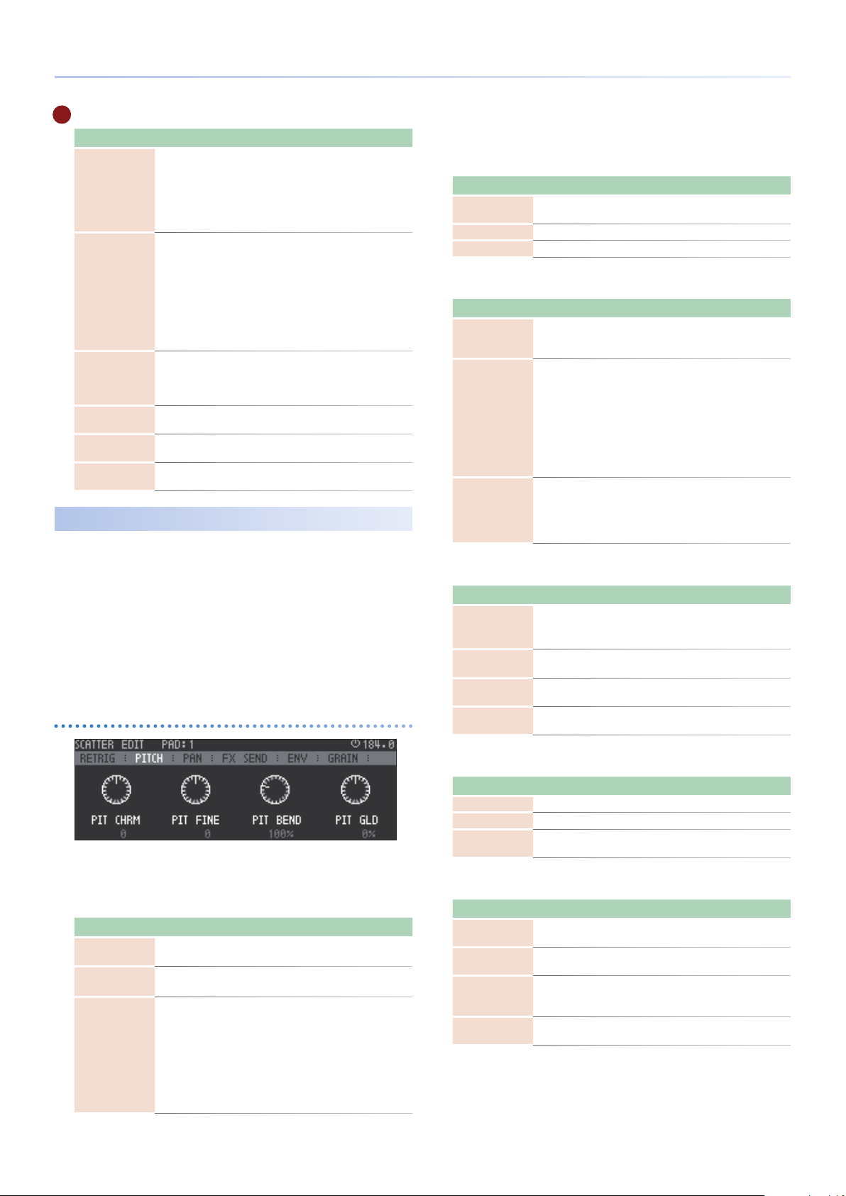
SCATTER
E SET
Parameter Value Explanation
Selects the position at which Scatter is
EX T,
POS
SPLIT
LOOP-HOLD OFF, ON
SCALE
LENGTH 1–16
MEASURE 1–8
PC,
TRACK1–8,
MIXOUT
1/1, 1/2, 1/3, 1/4,
1/5, 1/6, 1/7, 1/8,
1/9, 1/10, 1/11,
1/12, 1/13, 1/14,
1/15, 1/16
1/8, 1/16, 1/32,
1/4T, 1/8T, 1/16T
inserted.
EXT: Input from the EXT IN jacks
PC: Input from the USB PC-IN port
TRACK 1-8: Output of tracks 1–8
MIXOUT: Before the compressor
Species the width of the divisions when
dividing the clip.
For example,
if
SCALE: 1/16, LENGTH: 16, and MEASURE: 1, then
SPLIT: 1/16 0sixteenth notes
SPLIT: 1/12 0eighth note triplets
SPLIT: 1/8 0eighth notes
* Step numbers beyond the number of divisions
specied by SPLIT are ignored.
This lets you loop the playback while
holding the audio that is loaded into Scatter.
If you change the tempo, the playback
speed and pitch will change simultaneously.
Species the beat that is the basis of the
measure.
Species the basic number of beats (SCALE)
in a measure.
Species the number of measures used by
Scatter.
Detailed Editing
You can edit the eect individually for each pad and step.
Hold down the [SHIFT] button and press the PAD MODE
1.
[SCATTER] button.
The SCATTER menu appears.
Press the [ENTER] button to select the item that you want to
2.
edit.
* Step cannot be edited if pads are assigned to steps.
* When you edit a step, the step is lit red.
Editing a step/pad
*1 ORANGE, YELLOW, GREEN, BLUE, PURPLE, PINK, WHITE, SKYBLUE, P.YELLOW,
P.BLUE, P.PINK, L.RED, L.ORANGE, L.YELLOW, L.GREEN, P.GREEN, L.SKYBLUE,
L.BLUE, L.PURPLE
REVERSE
Parameter Value Explanation
SIZE 1–16
MUTE OFF, ON Mutes the sound.
REVERSE OFF, ON Plays in reverse.
Species the range of steps to which the
eect is applied.
RETRIG
Parameter Value Explanation
RETRIG 1–32
RETRIG GLD 1/32–OFF–32, Inf
HOLD OFF, x1 - x16
Repeatedly plays the sound for the specied
number of times within the range of steps
specied by SIZE.
Gradually applies change to the sound
specied by Retrig.
This is eective when you want the glitch
eect to change over time.
You can also produce change over a longer
time by raising Hold.
By setting this in the opposite direction than
a paired parameter, you can create large
change.
Repeatedly plays the range of steps specied
by SIZE for the specied number of times.
If this is OFF, playback continues to the end
of the steps available, regardless of the step
range.
PITCH
Parameter Value Explanation
PIT CHRM
(PITCH CHRM)
PIT FINE
(PITCH FINE)
PIT BEND
(PITCH GLIDE) -400%–400%
PIT GLD
-24 (-2oct)
0 (Original)
+24 (+2oct)
-100cent–0cent–
+100cent
(PITCH BEND) 1%–100%–400%
Species the pitch in semitone units.
Finely adjusts the pitch.
Smoothly varies the pitch across a wide
range.
Applies gradual change to the specied
pitch.
You can use the [C1]–[C4] knobs to edit the parameters shown in
the screen.
SETTING
Parameter Value Explanation
COLOR *1
SEQ
MASK OFF, ON
Default,
1–16
Species the pad color.
* This setting is only for PAD.
Species the timing of playback.
* This setting is only for STEP.
Species whether playback of another step
will overlap during playback.
If you raise Size or Hold to extend the
playback time of the step, and do not want
it to overlap the playback of another step,
you can turn this ON so that the step whose
timing overlaps is muted.
However, the step for which this is turned
ON is not muted.
PAN
Parameter Value Explanation
PAN L128–0–127R Species the panning of the sound.
LEVEL 0–255 Adjusts the volume.
(LEVEL GLIDE) -255–0–+255
LEV GLD
Applies gradual change to the sound
specied by LEVEL.
FX SEND
Parameter Value Explanation
MFX1 0–255
MFX2 0–255
FX SEND 0–255
DRY 0–255
Species the send amount of Scatter to
MFX1.
Species the send amount of Scatter to
MFX2.
Species the send amount to the SEND/
RETURN jacks.
* SEND/RETURN POS must be set to SCATTER.
Species the volume of sound that does not
pass through the eect.
39
Page 40

SCATTER
ENV
Parameter Value Explanation
ATK TIME 0ms–1000ms
DCY TIME 0ms–1000ms
GRAIN
Parameter Value Explanation
GRAIN
Default,
1–16
Species the speed at which the volume is
gradually raised when the eect starts being
applied. With a setting of 0ms this has no
eect.
Species the speed at which the volume
is gradually lowered when the eect stops
being applied.
With a setting of 0ms this has no eect.
In some cases, an extremely high setting of
DCY TIME could overlap with the operation
of ATK TIME, resulting in silence.
Lets you change the grains played back by
each step.
Editing MFX
Edit the parameters of the selected eect.
“MFX/IFX Parameters” (p. 84)
&
Parameter Explanation
MFX Type
MFX parameters
Turn the eect on/o, and select the type of eect
to use.
To turn the eect on, add a “(“ symbol to the check
box located beside the eect name.
Turns MFX on/o, and selects the type of MFX to use. To turn
MFX on, add a “(“ symbol to the check box located beside
the eect name.
“MFX/IFX Parameters” (p. 84)
&
Edit the parameters of the selected MFX.
“MFX/IFX Parameters” (p. 84)
&
-
40
Page 41

Editing the TONE Track
A tone track is a track that provides PCM/VA synthesis and sample
playback functionality.
Use a tone track when you want to play pitched phrases.
Simple Sound Editing
In the home screen, use the cursor buttons to select the
1.
tone track that you want to edit.
* If the sound source is Clip, select the clip that you want to edit.
Hold down the [SHIFT] button and press the [SOUND]
2.
button.
The TONE EDIT screen appears.
Use the cursor buttons to select an icon, and use the [C1]–
3.
[C4] knobs to edit.
Press the [FUNC] button to access the second page of the editing
items.
CTRL
Here you can make settings related to voicing.
Parameter Value Explanation
OCT
(Octave Shift)
VOICE
(Mono/Poly)
PORTAMENT
(Portamento Switch)
P.TIME
(Portamento Time)
-3–+3
MONO, POLY
OFF, ON
0–127
Species the pitch of the tone in octave
units (maximum of ±3 octaves).
Species whether the tone plays
polyphonically (POLY) or monophonically
(MONO).
MONO: Only the note of the last-played
key is played, one note at a time.
POLY: Multiple notes can be played
simultaneously.
Species whether the portamento (*1)
eect is applied (ON) or not applied (OFF).
Species the time over which the pitch
changes when using portamento. Higher
settings will cause the pitch change to the
next note to take more time.
Parameter Value Explanation
GROUP TYPE
(Wave Group Type)
BANK
(Wave Bank) A, B, C
WAVE
(Wave Number L/R)
FORM
PW 0–127
PWM -63–+63
INT, SAMP
Species the wave number within the group specied by Wave
Group.
Species the sample number when TYPE is SAMP.
* In EASY MODE, the same waveform is specied for L and R.
SAW, SQR, TRI, SIN,
RAMP, JUNO, TRI2,
TRI3, SIN2
OSC (PCM-SYNC)
Parameter Value Explanation
WAVE
(PCM-Sync Wave No.)
Species the wave that sounds when OSC Type is PCM-Sync.
The PCM-Sync oscillator is eective when Structure is SYNC and
set to Slave (the sync-modulated Partial 1, 3).
OSC (SuperSAW)
Parameter Value Explanation
DETUNE
(SuperSAW Detune)
0–127
INT: When OSC TYPE is PCM, the internal
waveforms of the MC-707 are used.
SAMP: When OSC TYPE is PCM, the
waveforms loaded into the project are
used.
Species the bank (A–C) that is sounded
when OSC Type is INT.
Species the wave that is sounded when
OSC Type is VA.
SAW: Sawtooth wave
SQR: Square wave
TRI: Triangle wave
SIN: Sine wave
RAMP: Ramp wave
JUNO: Modulated sawtooth wave
TRI2: Triangle wave variation
TRI3: Triangle wave variation
SIN2: Sine wave variation
This is an eect obtained by varying the
pulse width duty cycle to modify the
waveform.
It is available when OSCType is VA, and also
allows you to create eects with other than
SQR (square wave).
Species the amount (depth) of LFO
applied to PW (pulse width).
LFO follows the settings of LFO2.
Species the width of pitch variance
between the seven sawtooth waves that
are layered within one oscillator.
Higher values produce greater pitch
variance. (When doing this, OSC Detune
changes the pitch for each of the seven
sawtooth waves by the same width.)
*1 Portamento is an eect that smoothly changes the pitch from
one key to the next key that you press. Applying portamento
when Mono/Poly is set to “MONO” will produce an eect
reminiscent of the slide performance technique on a violin.
OSC 1–4
Here you can make settings for the oscillators of each partial.
Parameter Value Explanation
Species the oscillator type.
PCM: Sound is produced by PCM. This
sounds the wave specied by Wave Group
and Wave Number L/R.
VA: Sound is produced by an analog-
OSC
(OSC Type)
OFF, PCM, VA, PCMSync, SuperSAW,
Noise
modeled wave generated by calculation.
This sounds the wave of the number
specied by Waveform.
PCM-Sync: Sound is produced by the wave
specied by the PCM-Sync Wave Number.
SuperSAW: Sound is produced by
SuperSAW.
Noise: White noise is produced.
OSC (common to P2)
Parameter Value Explanation
SW OFF, ON Turns the partial on/o.
COARSE -48–+48
FINE -50cen–+50cen
VOL 0–127 Species the volume of the partial.
Species the pitch in semitone units
(maximum ±4 octaves).
Species the pitch in one-cent units
(maximum ±50 cents).
41
Page 42
Editing the TONE Track
STRUCT
Structure lets you play two partials as a pair.
By using partial 1 or 3 (the carrier) to modulate the other partial 2 or
4 (the modulator), you can create a wide range of tonal characters.
Parameter Value Explanation
Partial 2 is used to modulate the sound of partial 1.
OFF o
This implements the oscillator sync function
that is provided by analog synthesizers.
SYNC
OSC1-2/OSC3-4
RING
XMOD
XMOD2
OSC1 / OSC3 0–127 Adjusts the volume of OSC 1/3.
OSC2 / OSC4 0–127 Adjusts the volume of OSC 2/4.
RING
(RING1-2 Level) 0–127 Adjusts the volume of ring modulation.
0–9600 [cent]
MOD (XMOD)
(XMOD)
0–127 (XMOD2)
The oscillator of partial 1 is reset at pitch
cycles of partial 2.
* This is available only when OSC Type is Virtual
Analog or PCM Sync.
This implements the ring modulator that is
provided by analog synthesizers.
The output of partial 2 is multiplied with
partial 1.
“RING” (p. 63)
&
This implements the cross modulation
function that is provided by analog
synthesizers.
The output of partial 2 is applied as the
pitch of partial 1.
“XMOD” (p. 63)
&
Adjusts the depth of cross modulation.
PENV
Here you can make pitch envelope settings.
Parameter Value Explanation
Species the depth of the pitch envelope.
Higher values make the pitch envelope
DEPTH
(Depth) -100–+100
ATTACK (T1) 0–1023
(T3) 0–1023
DECAY
(L3) -511–+511
SUSTAIN
produce greater change. Negative “-” values
invert the shape of the envelope.
If the OSC Type is other than VA, this is
limited to ±63.
Species the time over which the initial
value changes to the maximum value after
the note starts.
Species the time over which the SUSTAIN
value is reached following the ATTACK.
Species the sustain value of the pitch
envelope.
LFO
Here you can make LFO settings.
Parameter Explanation
Species the LFO waveform.
SIN Sine wave
TRI Triangle wave
SAW-UP Sawtooth wave
SAW-DW Sawtooth wave (negative polarity)
SQR Square wave
RND Random wave
TRP Trapezoidal wave
S&H
FROM
RAT E 0–1023, 1/64T–4
(Filter Depth) -100–+100
>CUTOFF
(Pitch Depth) -100–+100
>PITCH
>AMP -100–+100
>PAN -63–+63
CHS
VSIN
STEP
Sample and Hold wave (changes the LFO
value once every cycle)
Sine wave modied by a VSIN chaos wave.
The amplitude of a sine wave is randomly
changed once every cycle.
Modied sine wave. The amplitude of the
sine wave is randomly varied once every
cycle.
A waveform generated from data specied
by LFO Step 1–16.
This produces a xed pattern of stepped
change like a step modulator.
You can edit this in the TONE PARTIAL EDIT
screen.
&
This is available if Rate Sync is OFF.
It species the LFO cycle regardless of the
tempo. Higher values shorten the LFO
cycle.
Species the depth at which the LFO is
applied to the cuto frequency.
Species the depth at which the LFO is
applied to pitch.
* If OSC Type is other than Virtual Analog, the
Species the depth at which the LFO is
applied to volume.
Species the depth at which the LFO is
applied to pan.
FENV
Here you can make lter envelope settings.
Parameter Value Explanation
ATTACK
(T1) 0–1023
(T3) 0–1023
DECAY
(L3) 0–1023
SUSTAIN
(T4) 0–1023
RELEASE
Species the time over which the initial
value changes to the maximum value after
the key is pressed.
Species the time over which the SUSTAIN
value is reached following the ATTACK.
Species the sustain value of the lter
envelope.
Species the time over which the minimum
value is reached after the key is released.
Refer to “Detailed Sound Editing” (p.
43).
range is limited to -63–+63.
42
MATRIX
Here you can connect various parameters as if you were patching
them.
You can connect up to four parameters.
Parameter Value Explanation
Species the control-source signal.
FROM
TO
DEPTH (Depth) -63–+63
For an explanation
of each parameter,
refer to the
parameter list.
* If you specify SycCtrl 1–4, you can use the
panel [FILTER] [MOD] [FX] knobs to control
the parameters.
Species the parameter that is controlled.
For an explanation of each parameter,
&
refer to “Parameter List” (p. 61).
Species the amount (depth) by which the
parameter is varied.
Page 43

Editing the TONE Track
MIX
Here you can set the reverb, delay, pan, and level of the total eect.
Parameter Value Explanation
LEVEL
(MIX LEVEL)
PAN L64-63R Species the pan of sound.
>REVERB
(Reverb Send) 0–127
(Delay Send) 0–127
>DELAY
0-127 Species the volume of the clip.
Species the amount sent to TOTAL FX
REVERB.
Species the amount sent to TOTAL FX
DELAY.
FILTER
Here you can make lter settings.
Parameter Value Explanation
Selects the type of TVF lter.
OFF: O
LPF: Low pass lter
TVF TYPE
VCF TYPE
TYPE TVF, VCF
(Cuto) 0–1023
CUTOFF
(Resonance) 0–1023
RES
(Env Depth) -63–+63 Species the depth of the lter envelope.
ENV DEP
KEYF -200–+200
SLOPE
OFF, LPF, BPF, HPF,
PKG, LPF2, LPF3
FLAT, TYPE-JP,
TYPE-M, TYPE-P
-12, -18, -24 [dB/
Oct]
BPF: Band pass lter
HPF: High pass lter
PKG: Peaking lter
LPF2: Low pass lter 2
LPF3: Low pass lter 3
Selects the type of VCF lter when the lter
TYPE is VCF.
Each of these simulates the operation of an
analog synthesizer’s LPF.
Select either TVF or VCF as the lter type.
* TVF stands for Time Variant Filter, and is a
lter that allows detailed settings to be made
for the time-varying change in the sound’s
frequency components.
If VCF is selected, the simultaneous
polyphony will be less than when TVF is
selected.
Selects the frequency at which the lter
begins to have an eect on the waveform's
frequency components.
Boosts the region of the sound near the
cuto frequency, adding a distinctive
character to the sound.
Set this if you want the cuto frequency to
change according to the keyboard position
of the note you play.
This button selects the slope (steepness) of
the lter.
For VCF, you can choose -12, -18, or -24.
For TVF, you can choose only -12 or -24.
If the lter TYPE is TVF, the following
limitations apply.
Only -12 dB or -24 dB can be specied.
Even if you specify -18 dB, the sound
engine operates internally with the -12 dB
setting.
If you specify -24 dB, the simultaneous
polyphony will be less than when -12 dB is
selected.
EQ
Here you can make equalizer settings.
Parameter Value Explanation
SW OFF, ON Turns the equalizer on/o.
LOW -24–+24 [dB] Gain of the low frequency range.
MID -24–+24 [dB] Gain of the mid frequency range.
HIGH -24–+24 [dB] Gain of the high frequency range.
MIDQ 0.5–16.0
LOW 20–16000 [Hz] Frequency of the low range.
MID 20–16000 [Hz] Frequency of the mid range.
HIGH 20–16000 [Hz] Frequency of the high range.
Bandwidth of the mid frequency range.
Set a higher value for Q to narrow the
range to be aected.
EFFECT
Here you can make eect settings.
Parameter Value Explanation
SWITCH OFF, ON Turns the eect on/o.
TYPE
Eect parameters
Refer to the MFX/
IFX parameters.
Switches the type of eect.
The displayed parameters depend on the
eect type that is selected.
Detailed Sound Editing
How a Tone Is Constructed
A tone consists of four (Partial 1–4) sets of OSC, Filter, AMP, LFO × 2, and
EQ settings, together with multi-eect (MFX) settings.
You can create sounds by combining the four partials.
Each partial can be turned on/o, allowing you to select which partials
produce sound.
Partial 4
Partial 3
Partial 2
Partial 1
LFO 1
OSC Filter
Pitch Env Filter Env Amp Env
LFO 2
Amp
EQ
MFX
AMP
Here you can make amp envelope settings.
Parameter Value Explanation
ATTACK
(T1) 0–1023
(T3) 0–1023
DECAY
(L3) 0–1023
SUSTAIN
(T4) 0–1023
RELEASE
PAN PTL1–4
(Pan) L64–63R Species the pan of each partial’s sound.
Species the time over which the initial
value changes to the maximum value after
the key is pressed.
Species the time over which the SUSTAIN
value is reached following the ATTACK.
Species the sustain value of the amp
envelope.
Species the time over which the minimum
value is reached after the key is released.
OSC (oscillator)
This selects the waveform that is the basis of the sound, and
species how its pitch will change.
Filter
This modies the frequency components of the sound.
Amp (amplier)
This creates changes in volume and pan.
43
Page 44

Editing the TONE Track
LFO (Low Frequency Oscillator)
LFO stands for Low Frequency Oscillator, and is an oscillator with a
very slow cycle. It can output waveforms such as sine wave, triangle
wave, square wave, or sawtooth wave.
By using the LFO to modulate another audio signal, you can create
eects such as vibrato or tremolo.
PARTIAL EDIT Screen
Here you can make settings for each partial.
In the TONE EDIT screen, select an icon such as OSC or
1.
FILTER, and then press the [ENTER] button.
The PARTIAL EDIT screen appears.
Select the general category of
parameter that you want to edit.
Use the [C1]–[C4] knobs to edit the parameters that are shown for
each knob.
Select the category of parameter
that you want to edit.
COMMON SETTING Screen
Here you can make settings for the tone.
In the TONE EDIT screen, select the CTRL, STRUCT, or MIX
1.
icon, and then press the [ENTER] button.
The TONE COMMON SETTING screen appears.
Select the category of parameter that you want to edit.
Use the cursor buttons or the [C1] [C2] knobs to switch categories.
Use the [C3] knob to select the parameter that you want to edit, and
use the [C4] knob to edit the value.
You can also use the cursor buttons to select a parameter.
For details, refer to “Parameter List” (p. 61).
If you want to edit multiple partials simultaneously, press the [C1
(partial 1)
], [C2
(partial 2)
], [C3
(partial 3)
], or [C4
(partial 4)
] knob. Partials
that can be edited are highlighted.
By holding down the [SHIFT] button and pressing a [C1]–[C4] knob,
you can turn the corresponding partial on/o.
For details, refer to “Parameter List” (p. 61).
UTILITY window
Here you can copy or initialize a partial. You can also initialize a tone.
Press the [FUNC] button.
1.
The UTILITY screen appears.
Use the cursor [<] [>] buttons to switch menu items.
2.
Menu Explanation
PARTIAL COPY
PARTIAL INITIALIZE
TONE INITIALIZE
Copies a partial.
Use the [C1]–[C4] knobs to make settings, and press the
[ENTER] button to execute.
Initializes a partial.
Use the [C1]–[C4] knobs to make settings, and press the
[ENTER] button to execute.
The contents of INITIAL TONE are assigned.
Initializes the tone.
Press the [ENTER] button to execute.
* The currently-edited sound is deleted.
44
Page 45

Editing the DRUM Track
A drum track is a track that provides PCM synthesis and sample
playback functionality.
Simple Sound Editing
In the home screen, use the cursor buttons to select the
1.
drum track that you want to edit.
* If the sound source is Clip, select the clip that you want to edit.
Hold down the [SHIFT] button and press the [SOUND]
2.
button.
The KIT EDIT screen appears.
A
B
C
Use the cursor buttons to select an icon.
3.
Use the [C1]–[C4] knobs to edit.
4.
You can also select an icon and press the [ENTER] button to edit.
MEMO
Press the [FUNC] button to access the second page.
A PAD
You can use the [C1]–[C4] knobs to perform simple editing for the
selected pad.
Press the [ENTER] button to open the edit menu.
Parameter Value Explanation
LEVEL 0–127 Adjusts the volume.
COARSE -24–+24 Adjusts the pitch in semitone units.
Species the time over which the sound
RELEASE 0–1023
REVERB 0–127
FINE -50cen–+50cen Finely adjusts the pitch in one-cent units.
PAN L64–63R Species the pan of the sound.
ENV MODE NO -SUS, SUSTAIN
DELAY 0–127
disappears after the key is released.
Larger values produce a longer decay, and
shorter values produce a crisper sound.
Species the amount sent to TOTAL FX
REVERB.
Species the behavior when a pad is
pressed.
NO-SUS: The volume immediately starts
decaying when you press the pad.
SUSTAIN: The volume starts decaying
when you release the pad.
Species the amount sent to TOTAL FX
DELAY.
With a pad selected, press the [ENTER] button to access the pad
edit menu. Here you can exchange or edit sounds.
You can use the [C1]–[C4] knobs to perform simple editing of the
sound.
D
E
B COMP (DRUM+COMP track only)
If you select “COMP” and then press the [ENTER] button, the
compressor setting screen appears.
Six channels of compressors can be applied to one (and only one)
of the drum tracks.
When you create the track, specify whether it will have these
compressors.
If you use this track, the maximum number of Looper tracks is
reduced from six to four.
C SET
When you select “SET” and press the [ENTER] button, the setting
screen for the part parameters and drum kit appears.
You can use the [C1]–[C4] knobs to edit the reverb, delay, pan, and
level for the total eect.
Parameter Value Explanation
LEVEL
(MIX LEVEL)
PAN L64–63R Species the pan of the sound.
>REVERB
(Reverb Send) 0–127
(Delay Send) 0–127
>DELAY
0-127 Species the volume of the clip.
Species the amount sent to TOTAL FX
REVERB.
Species the amount sent to TOTAL FX
DELAY.
D MFX
Here you can edit the eect settings.
Parameter Value Explanation
SWITCH OFF, ON Turns the eect on/o.
TYPE
Eect parameters
Refer to the MFX/
IFX parameters.
Switches the eect type.
The parameters shown depend on the
selected eect type.
For details, refer to “Parameter List” (p. 61).
E NAME
Press the [ENTER] button to access the drum kit (KIT) name editing
screen.
Operating the Unit Explanation
Cursor [<] [>] buttons Selects the character to edit.
[C2] knob
[C3] knob [C4] knob,
[VALUE] knob
Press the [C2] knob Inserts a space.
Press the [C3] knob Deletes a character.
Switches between uppercase, lowercase,
numerals, and symbols.
Change the character.
45
Page 46

Editing the DRUM Track
Pad Settings
(PAD MENU)
Here you can assign an instrument to each pad.
In PAD MENU you can change the instrument, and load or edit samples.
Hold down the [SHIFT] button and press the [SOUND]
1.
button.
The KIT EDIT screen appears.
Use the cursor buttons to select the pad that you want to
2.
edit, and then press the [ENTER] button.
The DRUM INST MENU screen appears.
Editing an Instrument
(INST EDIT)
Here’s how to edit the instrument that’s loaded into the pad.
Use the cursor buttons to select “INST EDIT,” and then press
1.
the [ENTER] button.
The DRUM INST SETTING screen appears.
Select the category of parameter that you want to edit.
Use the cursor buttons or the [C1] [C2] knobs to switch categories.
Use the cursor buttons or the [C3] knob to select the parameter that
you want to edit, and use the [C4] knob to edit the value.
“Parameter List” (p. 61)
&
* If sample is selected as the WAVE GROUP TYPE, you can move the cursor to
Wave Number and press the [ENTER] button to edit the waveform.
Changing the Pad’s Sound (Instrument)
(INST SELECT)
Use the cursor buttons to select "INST SELECT," and then
1.
press the [ENTER] button.
The DRUM INSTRUMENT browser appears.
In the DRUM INSTRUMENT browser, instruments or sample les can
be loaded into a kit.
PRESET: Load an instrument or kit from the MC-707’s presets
5
PROJECT: Load an instrument from a project saved on the SD card
5
WAVE FILE: Load a sample le from the SD card
5
Editing a Sample
(SAMPLE EDIT)
Here’s how to edit the user sample that’s loaded.
Use the cursor buttons to select “SAMPLE EDIT,” and then
1.
press the [ENTER] button.
The SAMPLE EDIT screen appears.
Parameter Value Explanation
START 0–8388607
LOOP 0–8388607 Species the loop position.
END 0–8388607
ZOOM x65536–x1 Zooms the waveform display in or out.
MODE
LEVEL 0–127 Adjusts the volume.
TUNE
gain 0db, +6db, +12db Species the sample’s approximate volume.
Original Key C-1–G9 Registers the sample’s pitch.
FWD, ONE-SHOT,
REV, REV-ONE
-50.0 cent–50.0
cent
Species the position at which playback
starts.
Species the position at which playback
ends.
Species the playback method.
Finely adjusts the pitch.
46
* The waveform specied as the instrument’s WMT1 is edited.
* If you want to edit the WMT2–3 waveform, move the cursor to WAVE NUMBER
in the INST EDIT screen, and press the [ENTER] button.
Page 47

Editing the DRUM Track
Editing the Instrument Name
The DRUM INST NAME screen appears, allowing you to edit the
instrument name.
Use the cursor buttons to select “INST NAME EDIT,” and then
1.
(INST NAME EDIT)
press the [ENTER] button.
The DRUM INST NAME screen appears.
Operating the Unit Explanation
Cursor [<] [>] buttons Selects the character.
[C2] knob
[C3] knob [C4] knob,
[VALUE] knob
Press the [C2] knob Inserts a space.
Press the [C3] knob Deletes a character.
Pad Editing
(PAD EDIT)
Switches between uppercase, lowercase,
numerals, and symbols.
Change the character.
Here’s how to edit pad settings.
Use the cursor buttons to select “PAD EDIT,” and then press
1.
the [ENTER] button.
The DRUM PAD SETTING screen appears.
* Pad settings are maintained even if you change instruments.
EQ tab
Here you can make EQ settings for the pad.
For details, refer to Drum Kit Tone Parameters (Drum), “PAD EQ” (p.
75).
CTRL tab
Here you can edit the control parameters.
For details, refer to Drum Kit Tone Parameters (Drum), “PAD CTRL”
(p. 75).
Initializing an Instrument
(INIT INST)
Here’s how to initialize the instrument that’s loaded into the pad.
Use the cursor buttons to select “INIT INST,” and then press
1.
the [ENTER] button.
A conrmation message appears.
Use the cursor [<] [>] buttons to select “O K,” and then press
2.
the [ENTER] button.
The instrument is initialized.
NOTE
The instrument being edited is deleted.
47
Page 48

LOOPER Track
This is a track that can play back audio les, or record and play back
audio from the input of a track, EXT IN, or a USB-connected computer.
To load a sample into a looper track
“Selecting Sounds (Sound Browser)” (p. 26)
&
“Importing Clips (Clip Browser)” (p. 25)
&
Making Looper Settings
Hold down the [SHIFT] button and press the [SOUND]
1.
button.
The LOOPER MENU screen appears.
Playback Settings
Here’s how to make playback-related settings for a Looper track.
Hold down the [SHIFT] button and press the [SOUND]
1.
button.
The LOOPER MENU screen appears.
Use the cursor buttons to select “SET (EDIT LOOPER
2.
SETTING),” and then press the [ENTER] button.
The LOOPER COMMON SETTING screen appears.
Select the category of the parameter that you want to edit
Use the cursor buttons or the [C1] [C2] knobs to switch categories.
Parameter Value Explanation
This parameter applies to time stretch.
Stretch Window
Reverse OFF, ON
1.0, 0.75, 0.5, 0.375,
0.25
Higher values improve the audio quality.
If an unnatural impression results when
pitch shift or time stretch is used to create
a large amount of change, lowering this
value might improve the result.
OFF: The sample plays forward.
ON: The sample plays backward.
PITCH tab
Parameter Value Explanation
Species the pitch in semitone steps
Pitch Chromatic -24–+24
Pitch Fine -100–+100 Finely adjusts the pitch.
Pitch Shift 0%–400%
(maximum ±2 octaves).
This setting can also be made in PAD MODE
NOTE.
Smoothly modies the pitch in a wide
range.
KNOB CTRL tab
Parameter Value Explanation
Level 0–127 Species the volume.
Pan (CC#10) L64–63R Species the pan of the sound.
Delay Send Level
(CC#93)
Reverb Send Level
(CC#91)
0–127
0–127
Adjusts the amount sent to the total eect
delay.
Adjusts the amount sent to the total eect
reverb.
Editing the Sample's Waveform
(Playback Region and Time Stretch Settings)
Here you can specify the playback region of the sample, and make
settings for time stretch.
MEMO
About time stretch
Looper tracks support time stretch, so that a sample’s playback speed can
match the BPM without changing its pitch.
Use the cursor buttons or the [C3] knob to select the parameter that
you want to edit, and use the [C4] knob to edit the value.
SOUND tab
Parameter Value Explanation
Level 0–127
Pitch/Stretch OFF, TYPE1, TYPE2
48
Species the volume at which the sample
plays.
Selects the pitch shift / time stretch
method.
OFF: Time stretch is not used; the sample is
lengthened by changing its pitch.
* If OFF is selected, the settings in the PITCH
tab are ignored (pitch shift is not applied).
TYPE1: Time stretch optimized for melodic
material is applied.
TYPE2: Time stretch optimized for rhythm
material is applied.
Use the cursor [<] [>] buttons to switch parameters.
Parameter Value Explanation
START 0–8388607
END 0– -8388607
MEASURE 1–8
ZOOM 1x–65536x Zooms the waveform in or out.
SCALE 1/8, 1/16, 1/8T
LENGTH 1–16
Species the position at which the sample
starts playing.
Species the position at which the sample
stop playing.
Species the number of measures that the
sample plays.
If STRETCH is specied as ENDPOINT, the
playback speed changes to match the
number of measures.
Species the step resolution on which
MEASURE is based.
Species the number of steps on which
MEASURE is based.
Page 49

LOOPER Track
Parameter Value Explanation
Species how to set the tempo that is the
reference for time stretch.
END POINT: The tempo (BPM) is
automatically specied according to the
STRETCH
ORG BPM 20.00–250.00
END POINT, ORG
BPM
END POINT, START POINT, MEASURE, and
SCALE.
ORG BPM: The tempo (BPM) is specied
manually. The upper right of the screen
indicates “BPM: value.”
If BPM is 512 or higher, time stretch will
not occur correctly.
If STRETCH is set to ORG BPM, this species
the BPM of the sample before it was
stretched.
MFX Editing
Use the [C2] knob to select the eect type, and press
the [C2] knob to turn the eect on/o.
To turn the eect on, add a “(” symbol to the check
box located beside the eect name.
Editing the Sample Name
The LOOPER NAME screen appears, allowing you to edit the sample
name.
Use the cursor buttons to select “LOOPER NAME EDIT,” and
1.
then press the [ENTER] button.
The LOOPER NAME screen appears.
Operating the Unit Explanation
Cursor [<] [>] buttons Selects the character to edit.
[C2] knob
[C3] knob [C4] knob,
[VALUE] knob
Press the [C2] knob Inserts a space.
Press the [C3] knob Deletes a character.
* The edited name is shown in the content browser.
Switches between uppercase, lowercase,
numerals, and symbols.
Change the character.
Use the cursor buttons or the [C3] knob to select the parameter that
you want to edit, and use the [C4] knob to edit the value.
“MFX/IFX Parameters” (p. 84)
&
Parameter Value/Explanation
Turns MFX on/o, and selects the type of MFX that is used.
MFX Type
MFX parameters
Level 0–127
Dly Send 0–127
Rev Send 0–127
To turn MFX on, add a “(” symbol to the check box located
beside the eect name.
“MFX/IFX Parameters” (p. 84)
&
Edit the parameters of the selected MFX.
“MFX/IFX Parameters” (p. 84)
&
Species the MFX output volume.
Species the MFX depth when
applying MFX, or species the volume
of the original sound when not
applying MFX.
Species the level of the signal sent to
delay.
Species the level of the signal sent to
reverb.
49
Page 50

Editing a Clip’s Settings
Here’s how to specify a clip’s length and playback method.
Tone Tracks or Drum Tracks
Making sequencer settings
Hold down the [SHIFT] button and press the [MEASURE]
1.
button.
The CLIP SEQ SETTING screen appears.
Use the [C1]–[C4] knobs to make settings.
2.
Parameter Value Explanation
STEP LEN 1–128 Species the length of the clip.
1/8,
1/16,
SCALE
DIRECTION
SHUFFLE -50–+50
1/32,
1/4T,
1/8T,
1/16T,
FWD,
RE V,
FWD+REV,
INV,
RND
Species the step resolution.
1/8: eighth notes
1/16: sixteenth notes
1/32: thirty-second notes
1/4T: quarter note triplets
1/8T: eighth note triplets
1/16T: sixteenth note triplets
Species how the sequence plays.
FWD: Play forward from the rst step.
REV: Play backward from the last step.
FWD+REV: Play forward from the rst
step, and after reaching the last step, play
backward.
INV: Play even numbers and odd numbers
inverted.
RND: Play randomly.
Adjusts the strength of shue (bounce) for
the playback timing.
This can be set individually for each clip.
Parameter Value Explanation
Species the step resolution.
1/8: eighth notes
1/16: sixteenth notes
1/32: thirty-second notes
1/4T: quarter note triplets
1/8T: eighth note triplets
1/16T: sixteenth notes triplets
Species how the sequence plays.
FWD: Play forward from the rst step.
REV: Play backward from the last step.
FWD+REV: Play forward from the rst
step, and after reaching the last step, play
backward.
INV: Play even numbers and odd numbers
inverted.
RND: Play randomly.
Scale
Direction
1/8,
1/16,
1/32,
1/4T,
1/8T,
1/16T,
FWD,
RE V,
FWD+REV,
INV,
RND
LOOPER
Specifying the playback m
Hold down the [SHIFT] button and press the [MEASURE]
1.
button.
The CLIP SEQ SETTING screen appears.
Parameter Value Explanation
STEP LEN 1–128
REVERSE OFF, ON
ethod
Species the length of the clip.
* The same setting can also be made in the CLIP
settings screen ([SHIFT] + [CLIP]).
Species the sample playback method.
* The same setting can also be made in the CLIP
settings screen ([SHIFT] + [CLIP]).
Editing the settings of a
Hold down the [SHIFT] button and press the [CLIP] button.
1.
clip
The clip setting screen appears.
Use the cursor [ ] [ ] buttons to select a parameter, and use
2.
the [C4] knob to edit the value.
Parameter Value Explanation
Adjusts the strength of shue (bounce) for
Shue -50–+50
Transpose -12–+12
Bend Mute OFF, MUTE Disables bend (Tone only).
Step Length 1–128 Species the length of the clip.
the playback timing.
This can be set individually for each clip.
Shifts the playback transposition (Tone
only).
Editing the settings of a
Hold down the [SHIFT] button and press the [CLIP] button.
1.
clip
The LOOPER CLIP SETTING screen appears.
Use the cursor [ ] [ ] buttons to select a parameter, and use
2.
the [C4] knob to edit the value.
Parameter Value Explanation
Species the length of the clip.
Step Length 1–128
Reverse OFF, ON
* The same setting can also be made in
the MEASURE setting screen ([SHIFT] +
[MEASURE]).
Species the sample playback method.
* The same setting can also be made in
the MEASURE setting screen ([SHIFT] +
[MEASURE]).
50
Page 51
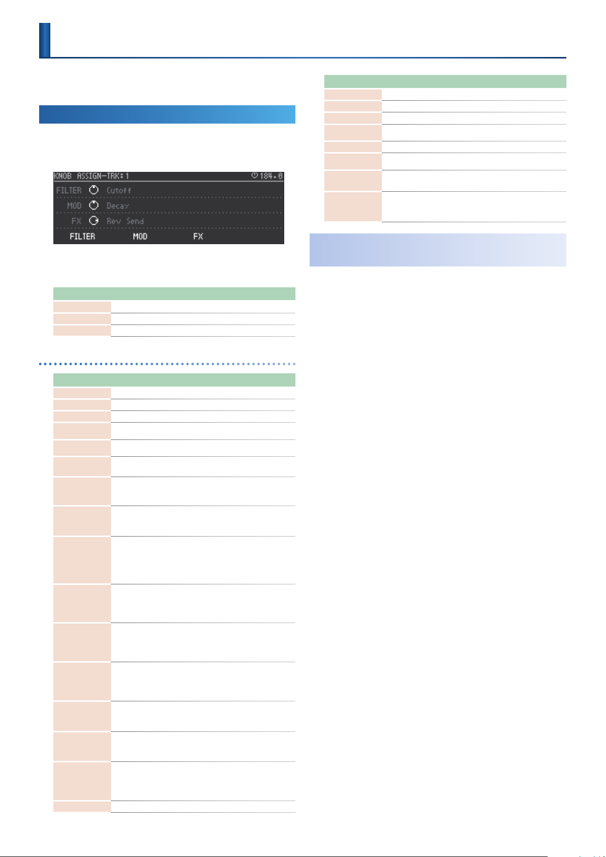
Assigning Parameters to the Knobs
(KNOB ASSIGN)
You can assign the desired parameters to each track’s [FILTER], [MOD],
and [FX] knobs, and use the knobs to control those parameters.
Operating the Unit
Press the [KNOB ASSIGN] button.
1.
The KNOB ASSIGN screen appears.
Here you can make knob assignments for the current track.
Use the [C1]–[C3] knobs to make the settings.
2.
Knob Explanation
C1 Species the [FILTER] knob assignment.
C2 Species the [MOD] knob assignment.
C3 Species the [FX] knob assignment.
Parameter list
Parameter Explanation
Delay Send Species the send level of the total eect to the delay.
Reverb Send Species the send level of the total eect to the reverb.
Pitch Bend (Tone only) Uses the FILTER, MOD, or FX knob as pitch bender.
Pitch Chrom
(Looper only)
Pitch Fine
Pitch Shift
(Looper only)
Reverse
(Looper only)
SYS-Ctrl1–4
Species the pitch in semitone steps (maximum ±2 octaves).
(Looper only) Finely adjusts the pitch.
Smoothly modies the pitch in a wide range.
OFF: The sample plays forward.
ON: The sample plays backward.
Connects to a parameter specied by MATRIX CONTROL in
SOUND EDIT.
For details, refer to “MATRIX” (p. 42).
&
Returning Parameter Values to the Default Value
Hold down the [CLEAR] button and press a [C1]–[C3] knob.
1.
The assigned parameter value returns to its default value.
Parameter Explanation
No Assign No assignment.
Level Adjusts volume.
Pan Adjusts pan.
Coarse Tune
(Tone, Drum only)
Fine Tune
(Tone, Drum only)
Portament
Porta Time
(Tone, Drum only)
Cuto
Resonance
(Tone, Drum only)
Attack
(Tone, Drum only)
Decay
(Tone, Drum only)
Release
(Tone, Drum only)
Vib Rate
(Tone only)
Vib Depth
Vib Delay
Oct Shift
(Tone only) Shifts the pitch in units of one octave.
Adjusts the pitch in units of one semitone.
Finely adjusts the pitch in units of one cent.
Species whether portamento is applied. Specify “ON” to apply
(Tone only)
portamento, or “OFF” if not.
Species the time over which the pitch changes when using
(Tone only)
portamento. Larger values lengthen the time over which the
pitch moves to the next note.
Adjusts the openness of the lter.
Larger values make the sound brighter, and smaller values make
the sound darker.
Boosts the region of the sound near the cuto frequency, adding
a distinctive character to the sound. Excessively raising this value
may cause oscillation, distorting the sound.
Larger values produce a stronger character, and smaller values
weaken the character.
Species the time from when the key is pressed until the sound
reaches the maximum.
Larger values make the attack more gradual, and smaller values
make the attack sharper.
Species the time from when the attack is completed until the
volume decays.
Larger values lengthen the time over which the volume decays,
and smaller values shorten the time.
Species the time from when the key is released until the sound
becomes inaudible.
Larger values produce a longer decay, and smaller values make
the sound crisper.
Adjusts the vibrato rate (the speed at which pitch is modulated).
Larger values modulate the pitch more rapidly, and smaller values
modulate it more slowly.
Adjusts the vibrato depth (the depth at which pitch is modulated).
(Tone only)
Larger values modulate the pitch more widely, and smaller values
modulate the pitch less widely.
Adjusts the time until vibrato (pitch modulation) starts to be
applied.
(Tone only)
Larger values lengthen the time until vibrato starts to be applied,
and smaller values shorten the time.
51
Page 52

Tempo Settings
Master Clock
Clip switching and play/stop occurs at intervals of the master clock.
This means that the performances of each track can be synchronized
regardless of the timing of operation.
The status of the master clock is shown by the circle displayed in the
upper right of the screen. When the master clock indication points to
12 o’clock (straight up), the clip is switched or the play/stop operation
is executed.
The cycle of the master clock is specied by “SCALE” and “STEP
LENGTH.”
Master Clock Settings
Hold down the [SHIFT] button and press the [TEMPO]
1.
button.
Parameter Value Explanation
TEMPO 40.00–300.00
1/8,
1/16,
SCALE
STEP LEN 2–128 Species the cycle.
1/32,
1/4T,
1/8T,
1/16T,
This is the tempo of the entire project.
In this page, you can also use the VALUE
dial to change the tempo.
Species the resolution.
1/8: eighth notes
1/16: sixteenth notes
1/32: thirty-second notes
1/4T: quarter note triplets
1/8T: eighth note triplets
1/16T: sixteenth note triplets
Tap Tempo
Holding down the [SHIFT] button and pressing the [ENTER] button
three or more times.
The tempo is specied as average timing at which you press the
button.
52
Page 53

Input and Output Settings
Input and Recording Settings
(INPUT/REC)
Here’s how to make external input settings, and settings for looper
recording.
Hold down the [SHIFT] button and press the [INPUT] button.
1.
The INPUT/OUTPUT/REC SETTING screen appears.
Parameter Value Explanation
MIC SENSE 0–7
EXT IN MONO, STEREO
EX T,
REC SRC
REC MEAS 1–8
PC,
TRK1–8,
MIXOUT
Species the MIC IN gain.
* This is valid when the rear panel input switch
is set to MIC IN.
Switches the EXT IN input between mono
or stereo.
Species the recording source for the
Looper.
EXT: Record from the EXT IN jacks.
PC: Record from the PC IN port of USB
audio.
TRK 1–8: Record from a track.
MIXOUT: Record the audio output of the
entire MC-707.
* If the USB Mix Select setting is POST T-FX, the
audio input from the USB MIX OUT port is not
recorded.
Species the clip length (number of
measures) that will be recorded.
Using an External Eect
(SEND/RETURN Jacks)
This allows you to connect an external eects device to the SEND/
RETURN jacks and use it as part of the MC-707’s eects.
Connect your eect unit to the SEND/RETURN jacks.
1.
External Eect
Hold down the [SHIFT] button and press the [INPUT] button.
2.
The input/output settings are displayed.
Use the cursor buttons to select the SEND/RETURN tabs,
3.
and make settings.
Parameter Value Explanation
SEND tab
OFF,
PC,
POS
LEVEL 0–255 Species the SEND output level.
SEND
RETURN tab
POS
LEVEL 0–255 Species the RETURN input level.
RETURN
TRACK1–8,
DELAY,
REVERB,
SCATTER,
MIXOUT
MONO,
STEREO
OFF,
PC,
TRACK1–8,
DELAY,
REVERB,
SCATTER,
MIXOUT
MONO,
STEREO
Species the position at which SEND/
RETURN is used.
Switches the SEND output between mono
and stereo.
Species the position at which SEND/
RETURN is used.
This is the same setting as in the SEND tab.
Switches the RETURN input between mono
and stereo.
Individually Outputting Each Track
(ASSIGNABE OUT)
A specied track can be output from the ASSIGNABLE OUT jacks.
The ASSIGNABLE OUT setting is made in the track settings.
Hold down the [SHIFT] button and press the [SEL] button.
1.
For details, refer to “Making Track Settings” (p. 20).
&
53
Page 54

UTILITY
System Settings
(SET)
In MENU, choose SET and make settings to specify the operation of the
pads, MIDI, and knobs.
These settings are saved in the MC-707 unit.
Hold down the [SHIFT] button and press the [KNOB ASSIGN]
1.
button.
The UTILITY MENU screen appears.
Use the cursor [<] [>] buttons to select “ S ET,” and then press
2.
the [ENTER] button.
The SYSTEM SETTING screen appears.
Use the cursor buttons to select the tabs, and make settings.
3.
CTRL tab
Here you can make settings for the pads and knobs.
Parameter Value Explanation
DIRECT: When a knob is moved, control
Knob Mode
Pad Curve Type
Pad Threshold 0–15
Pad Trigger
Sensitivity
USB Mix Select
DIRECT,
CAT CH
LINER,
EXP,
LOG,
FIX10-127
10–200
Pre T-FX,
Post T-FX
data of the corresponding position is
always output.
CATCH: Control data is output after the
knob passes through the current value of
the parameter.
Species how the volume changes in
response to the force of your strike on the
pad.
LINER: This is the normal setting. This
allows the most natural-feeling relation
between strike strength and volume
change.
EXP: Compared to LINEAR, this produces
greater volume change for stronger strikes.
LOG: Compared to LINEAR, this produces
greater volume change for softer strikes.
FIX10-127: Enters a specied xed value.
Species the pad’s minimum sensitivity so
that a trigger signal is read only if the pad is
struck more strongly than a specied level.
This can be used to prevent the pads from
picking up vibration from the environment.
Adjusts the sensitivity of the pads to
repeated strikes.
With lower values, the pads will accept
repeated strikes at a shorter time
interval. Increase this value if you don’t
want repeated strikes to be accepted
inadvertently.
Species whether sound that is input via
the USB-connected MIX OUT port is input
before or after TOTAL FX.
“Block Diagram” (p. 121)
&
Parameter Value Explanation
LAST: At startup, the project that was last
saved will be loaded.
INIT: At startup, a project will not be
loaded. A new project will be created.
Load Project
LAST,
INIT
MIDI tab
Parameter Value Explanation
Species the tempo source.
AUTO,
MIDI Sync
MIDI Sync Out1
MIDI Sync Out2
MIDI Sync Out USB
RX Start Stop
RX Start Stop USB
Track Channel 1-8 CH1–CH16 Species the MIDI channel of each track.
Device ID 17–32
Soft Through 1
Soft Through 2
USB-MIDI Thru 1
USB-MIDI Thru 2
INT,
MIDI,
USB
OFF,
ON
OFF,
ON
OFF,
ON
OFF,
ON
OFF,
ON
OFF,
ON
If this is “AUTO,” the tempo automatically
synchronizes to MIDI clock if MIDI clock is
being input via the MIDI IN connector or
the USB port.
If this is “INT,” the tempo specied on the
MC-707 is used.
Species whether clock, start, and stop
messages are transmitted (ON) or are not
transmitted (OFF) to the devices connected
to the corresponding MIDI port.
Species whether clock, start, and stop
messages are transmitted (ON) or are not
transmitted (OFF) to the USB-connected
device.
When synchronized to external MIDI clock,
this setting species whether the step
sequencer’s start/stop is controlled from
the device connected to the corresponding
MIDI port (ON) or is not controlled (OFF).
When synchronized to external MIDI
clock, this setting species whether step
sequencer’s start/stop is controlled from
the USB-connected device (ON) or is not
controlled (OFF).
When transmitting and receiving system
exclusive messages, the device ID numbers
of both devices must match.
If this is ON, MIDI messages that are
input from the MIDI IN connector are retransmitted without change from the MIDI
OUT connector.
Species whether MIDI messages received
at the USB port or MIDI IN port are
retransmitted without change from the
MIDI OUT connector and USB port (ON) or
not (OFF).
If this is ON, MIDI messages received at the
USB port are sent to the internal sound
engine and to the MIDI OUT connector,
and MIDI messages received at the MIDI IN
connector are sent together with messages
from the internal sound engine to the USB
port.
DISPLAY tab
Parameter Value Explanation
LCD Contrast 1–10 Adjusts the contrast of the display screen.
LCD Backlight 1–10
LED Brightness 1–10
LED Glow 1–10
DEMO Mode OFF, 1min–10min
Adjusts the brightness of the display
backlight.
Species the brightness of the fader and
button LEDs.
Adjusts the brightness when a button LED
is dimly lit.
Species the time (minutes) until the LED
demo is shown.
54
Page 55

Initializing a New SD Card
Hold down the [SHIFT] button and press the [KNOB ASSIGN]
1.
button.
The UTILITY MENU screen appears.
Use the cursor [<] [>] buttons to select “FORMAT,” and then
2.
press the [ENTER] button.
A conrmation message appears.
(FORMAT)
UTILITY
Use the cursor [<] [>] buttons to select "OK," and then press
3.
the [ENTER] button.
The system settings return to their factory-set state.
If you decide to cancel, use the cursor [<] [>] buttons to select
“CANCEL,” and then press the [ENTER] button.
As directed in the screen, turn the power o and then on
4.
again.
Optimizing the Internal Memory
(LOOPER OPTIMIZE)
As samples are loaded into the looper and then deleted, the free space
in memory can become fragmented, so that the available space cannot
be used eciently.
By using Looper Optimize, you can optimize the internal memory
usage and increase the storage that is available for recording.
Hold down the [SHIFT] button and press the [KNOB ASSIGN]
1.
button.
The UTILITY MENU screen appears.
Use the cursor [<] [>] buttons to select “O K,” and then press
3.
the [ENTER] button.
The SD card is initialized.
If you decide to cancel, use the cursor [<] [>] buttons to select
“CANCEL,” and then press the [ENTER] button.
Returning to the Factory Settings
(FACTORY RESET)
This returns the system settings to their factory-set state.
NOTE
If necessary, be sure to save the project before you execute FACTORY RESET.
Hold down the [SHIFT] button and press the [KNOB ASSIGN]
1.
button.
The UTILITY MENU screen appears.
Use the cursor [<] [>] buttons to select “FACTORY RESET,”
2.
and then press the [ENTER] button.
A conrmation message appears.
Use the cursor [<] [>] buttons to select “LOOPER OPTIMIZE,”
2.
and then press the [ENTER] button.
A conrmation message appears.
Usage: The amount of occupied storage space.
Fragment: The proportion that is fragmented. Higher values mean
that memory usage is less ecient, so that you can expect an
improvement in recordable time by executing Looper Optimize.
* Optimization is also performed when a project is loaded.
Use the cursor [<] [>] buttons to select “O K,” and then press
3.
the [ENTER] button.
Memory optimization is executed.
If you decide to cancel, use the cursor [<] [>] buttons to select
“CANCEL,” and then press the [ENTER] button.
55
Page 56

UTILITY
Using a Connected Computer to Manage the SD Card
By USB-connecting the MC-707 in Storage mode to your computer, you
can use the computer to manage the contents of the SD card in the
MC-707.
* Other operations cannot be performed while in Storage mode.
Make sure that the USB cable is not inserted in the MC-707.
1.
Hold down the [SHIFT] button and press the [KNOB ASSIGN]
2.
button.
The UTILITY MENU screen appears.
Use the cursor [<] [>] buttons to select “STORAGE MODE,”
3.
and then press the [ENTER] button.
The MC-707 is now in Storage mode.
Insert the USB cable, and connect it to your computer.
4.
Before disconnecting, use your computer to perform the
5.
appropriate operation for safely removing the external
device.
56
Page 57

List of Shortcut Keys
Switching Screens and Modes
Operation Operation
To access the quantize edit screen
To access the sound edit screen Press the [SOUND] button.
To access the UTILITY screen Press the [KNOB ASSIGN] button.
To access the master clock setting screen Press the [TEMPO] button.
To access the input/output and recording settings
screen
To access the project save screen Press the [FUNC] button.
To access the MOTION ERASE screen Press the MOTION [ON] button.
To switch to LAST STEP mode Press the MOTION [REC] button.
To recall SCENE 5 Press the SCENE [1] button.
To recall SCENE 6 Press the SCENE [2] button.
To recall SCENE 7 Press the SCENE [3] button.
To recall SCENE 8 Press the SCENE [4] button.
To edit PAD MODE “CLIP” Press the PAD MODE [CLIP] button.
To edit PAD MODE “NOTE” Press the PAD MODE [NOTE] button.
To edit PAD MODE “CHORD” Press the PAD MODE [CHORD] button.
To edit PAD MODE “SCATTER” Press the PAD MODE [SCATTER] button.
To edit the total eect Reverb Press the [REVERB] button.
To edit the total eect Delay Press the [DELAY] button.
To edit the total eect Multi-Eect Press the [MULTI] button. Select the MFX tab.
To edit the total eect Comp/EQ Press the [MULTI] button. Select the COMP tab or EQ tab.
To access the clip setting screen In the home screen, select the clip for which
To access the clip sequence setting screen Press the MEASURE [<] or [>] button.
Hold down the [SHIFT] button and
you want to make settings, then hold down the
[SHIFT] button and
Press the [QUANTIZE] button.
Press the [INPUT] button.
Press the [CLIP] button (below the [C2] knob).
Adjusting the Mix Sound
Operation Operation
To adjust the volume of the sound
To adjust the pan of the sound Turn the [C2] knob.
To adjust the delay send of the sound Turn the [C3] knob.
To adjust the reverb send of the sound Turn the [C4] knob.
Hold down the [SEL] button of the corresponding
track and
Turn the [C1] knob.
MOTION
Operation Operation
To delete a knob’s motion Hold down the MOTION [ON] button and
To punch-in motion Hold down the MOTION [REC] button and
Operate the [FILTER] [MOD] [FX] knob of the corresponding track.
Phrase Editing
Operation Operation
To step-record
To input Motion in a step
To mute the drum part
To enter weak drum beats Hold down the pad, and press the [STEP] button.
To clear the phrase from a clip
To clear the phrase from a drum part Press a pad.
To duplicate a phrase
(Tone track only)
When in Note mode,
(for each clip) Hold down the PAD MODE [MUTE] button, and press a pad.
Hold down the [CLEAR] button, and
When the CLIP SEQ SETTING screen (p. 50)
displayed,
Hold down the [REC] button and press the [STEP] button.
Hold down the [STEP] button, and operate the [FILTER] [MOD] [FX] knobs of the
corresponding track.
Press the [SEL] button of the corresponding track.
Hold down the [FUNC] button and press the MEASURE [>] button.
57
Page 58

List of Shortcut Keys
Performance
Operation Operation
To audition a track in your headphones
To mute a track Hold down the PAD MODE [MUTE] button and Press the [SEL] button of the corresponding track.
To mute a drum part
To switch parts without sounding the drums Hold down the PAD MODE [NOTE] button and
To start/stop each track Hold down the PAD MODE [CLIP] button and Press the [SEL] button of the corresponding track.
To forcibly return to the beginning of the pattern
during pattern playback
To silence sound that continues after stopping While stopped
(for each track)
(CUE) When in MUTE mode
Hold down the [SEL] button of the corresponding
track, and
During playback
Hold down the PAD MODE [MUTE] button and press a pad.
* The PAD MODE changes to CUE mode.
Press a pad.
Hold down the [SHIFT] button and press the [START/STOP] button.
Controller Values and Parameter Editing
Operation Operation
To specify the parameter operated by the total
eect knobs
To view the value of a knob
To change the parameter value more greatly Turn the [C1] [C2] [C3] [C4] knob or the [VALUE] knob.
To adjust the pad velocity curve Hold down the PAD MODE [NOTE] button and Turn the [VALUE] knob.
To specify tap tempo Hold down the [SHIFT] knob and Press the [ENTER] button three or more times.
To clear the Scatter pad parameters
To clear the Scatter Step parameter Press the [STEP] button.
To jump between eect type categories When the MFX EDIT screen is displayed Hold down the [SHIFT] button and turn the [C2] knob.
To move to the same parameter for each band
(low, mid, high) of the TOTAL COMP
Hold down the [REVERB], [DELAY], or [MULTI]
button that you want to assign, and
Hold down the [SHIFT] button and
When in Scatter mode
Hold down the [CLEAR] button and
While the TOTAL COMP EDIT screen is displayed Hold down the [SHIFT ] button and use the cursor [
Turn the [FX PRM] or [FX DEPTH] knob.
Move the knob.
Press a pad.
] [ ] buttons.
58
Page 59

Error Message List
Display Explanation Action/Explanation
Now Playing! This operation cannot be executed because playback is occurring. Stop playback, and then execute.
CLIP NOT EXIST!
EMPTY CLIP The clip that is the target of the operation does not exist.
EMPTY TRACK
CLIP NOT EMPTY
For new loop, delete the existing
clip!
TRACK NOT EMPTY The track paste-destination is not empty. Either select an empty track, or delete the applicable track before executing.
WRONG TRACK TYPE
PLEASE SELECT TRACK
PLEASE SELECT LINE
PLEASE SELECT CLIP
ALREADY USED!
File Write Error! Failed to save the project le.
Can’t Write
This le name is locked.
Abort. **** is locked le. The le could not be deleted because it is locked.
Now Playing. Please Stop the
Sequencer.
Abort! File can’t open The wave le could not be opened. The le or SD card that you attempted to load might be damaged.
Abort! File format error The sample le format is not supported by the MC-707.
Abort! File read error The le could not be read for some reason.
Abort! Memory full
Abort! Not enough contiguous
memory
Abort! Exceed the Max samples
count
Abort! Too short samples The le could not be imported because the sample is too short.
Abort! Too long samples The le could not be imported because the sample is too long.
Format SD CARD Error! Failed to format the SD card.
NO SD CARD
SD CARD PROTECTED The SD card is set to a write-protect state.
TOO MANY LOOPER TRACKS!
WAVE1 SAMPLE OFF
WAVE1 NOT USER SAMPLE
Memory Full!
The clip that is the target of the operation does not exist.
This appears if an empty clip is selected as the target of a copy or edit
operation.
The track that is the target of the operation does not exist.
This appears if an empty track is selected as the target of a copy or edit
operation.
The clip slot that is the target of the operation is already in use.
It is possible to simultaneously select the same clip number of all tracks (p.
14) and perform copy and paste, but the paste-destination clip slots must
all be empty.
When loading a looper clip, this message appears if you attempt to
overwrite an existing clip.
Looper clips cannot be imported by overwriting an existing clip.
The copy-source and copy-destination track types are dierent.
You can’t copy clips between tracks of dierent types.
A track is selected for copying, but a track is not selected as the pastedestination.
The clip line is selected for copying, but a clip line is not selected as the
paste-destination.
A clip is selected for copying, but a clip is not selected as the pastedestination.
The specied track type is already used.
This appears if a drum track with compressors is already in use, and you
attempt to create a new drum track with compressors.
Writing is not possible because the le is locked.
This operation cannot be executed because playback is in progress. Stop playback and then execute the operation.
The le could not be imported because there is insucient internal memory
in the MC-707.
Unable to allocate enough contiguous memory for importing.
Import was not possible because it would exceed the maximum number of
user samples.
The SD card is not inserted.
Alternatively, it is incompletely inserted.
The operation could not be executed because the maximum number of
looper tracks that can be created has been reached.
The sample cannot be edited because a user sample is not assigned to
WAVE1 of the instrument being edited.
The sample cannot be edited because a user sample is not specied for
WAVE1 of the instrument being edited.
The operation could not be executed because there is insucient looper
memory.
Make sure that the target clip is correctly selected.
Make sure that the target track is correctly selected.
Either select an empty clip slot, or delete clips before executing.
Copy the clip to a track type that is the same as the copy-source.
Select a track and then paste.
Select a clip line and then paste.
Select a clip and then paste.
Either delete the existing drum track with compressors, or use a
conventional drum track.
For some reason, the le could not be saved.
You might be able to solve this problem by formatting the SD card.
Before formatting the SD card, make a backup by saving any important les
to your computer.
You can’t save using the same name as a locked project.
As described in “Managing Projects” (p. 17), unlock the le and then
overwrite it, or save the le with a dierent name.
A locked project cannot be deleted.
If you want to delete the project, unlock it.
The MC-707 supports 32–96 kHz, 16-bit and 24-bit (mono/stereo) Wav
format les.
Use your computer to convert the le format, and try the operation again.
If the Wav le format you are attempting to read is not common, there
might be cases when the le cannot be read.
Use the Sample Bank browser (p. 19) to delete unneeded user samples.
It might be that the internal memory has been fragmented. Execute
“Optimizing the Internal Memory (LOOPER OPTIMIZE)” (p. 55).
If the same error occurs even after optimizing, delete unneeded looper clips
from the project.
The MC-707 can handle a maximum of 500 user samples.
Use the Sample Bank browser (p. 19) to delete unneeded user samples.
The length of samples that can be handled by a looper clip is from one
second to 60 seconds.
Use your computer to edit the Wav le to this length, and execute the
operation again.
* Depending on the tempo setting, there are cases in which an even shorter or
longer sample can be handled.
Turn o the power, rmly insert the SD card, and then turn the power on
again.
Remove the SD card, and change the position of the lock switch on its left
side.
Delete unneeded looper tracks, and execute the operation again.
Make sure that a sample is assigned to the instrument that you’re editing,
and execute the operation again.
Make sure that a sample is assigned to the instrument that you’re editing,
and execute the operation again.
Delete unneeded looper clips, and execute the operation again.
59
Page 60

Interoperation with Other Devices
Synchronizing with a DAW
The MC-707 can transmit and receive MIDI clock (F8) to synchronize its
tempo.
USB MIDI IN
USB MIDI OUT
MC-707Computer
Synchronizing with a TR-8S
The MC-707 can synchronize with a TR-8s by connecting the units via a
commercially available MIDI cable.
MIDI OUT MIDI IN
MC-707
TR-8S
60
Page 61

1
2
3
OFF
2
1
OFF
3
High note range
Pitch dierence from
equal temperament
Parameter
value
Low note range
C5
D4
C4
press D4 key
Pitch
Time
press C4 key
press C5 key
C5
D4
C4
press D4 key
Pitch
Time
press C4 key
press C5 key
Parameter List
ZEN-Core Tone Parameter
(Z-Core)
SOUND
Parameter Value Explanation
Level 0–127 Adjusts the overall volume of the tone
Pan L64–0–63R
Soft Level Sens 0–100
This determines how notes will be managed when the maximum
polyphony is exceeded.
LAST
Priority
LOUDEST
Analog Feel 0–127
Species whether the tone will play polyphonically (POLY) or
monophonically (MONO). The “MONO” setting is eective when
Mono/Poly
playing a solo instrument tone such as sax or ute.
MONO Only the last-played note will sound.
POLY
Coarse Tune -48–+48 [semitone]
Fine Tune -50–+50 [cent]
Octave Shift -3–+3
Stretch Tune Depth OFF, 1–3
Species the pan of the tone. “L64” is far left,
“0” is center, and “63R” is far right.
Species the amount of volume change
that occurs when you operate the soft pedal
(CC#67).
This is eective when specied for piano
sounds.
The last-played voices will be given priority,
and currently sounding notes will be turned
o in order, beginning with the rst-played
note.
The voices with the loudest volume will be
given priority, and currently sounding notes
will be turned o, beginning with the lowestvolume voice.
Applies time-varying change to the pitch
and volume of the tone that is producing
sound, adding a sense of variability. As you
increase this value toward the maximum,
the variability becomes greater, producing
instability.
Two or more notes can be played
simultaneously.
Adjusts the pitch of the tone’s sound up or
down in semitone steps (+/-4 octaves).
Adjusts the pitch of the tone’s sound up or
down in 1-cent steps (+/-50 cents).
Adjusts the pitch of the tone’s sound up or
down in units of an octave (+/-3 octaves).
This setting allows you to apply “stretched
tuning” to the tone (Stretched tuning is a
system by which acoustic pianos are normally
tuned, causing the lower range to be lower
and the higher range to be higher than the
mathematical tuning ratios would otherwise
dictate.). With a setting of “OFF,” the tone’s
tuning will be equal temperament. A setting
of “3” will produce the greatest dierence in
the pitch of the low and high ranges.
The diagram shows the pitch change relative
to equal temperament that will occur in the
low and high ranges. This setting will have
a subtle eect on the way in which chords
resonate.
Parameter Value Explanation
When LegatoSwitch is enabled and you play
legato, this species whether retriggering
occurs (0–12) or does not occur (OFF).
If this is o, only the pitch of the currentlysounding tones changes according to the
pitch of the key.
If this is set to 1–12, retriggering occurs
smoothly when the pitch dierence during
legato performance exceeds the specied
value.
For example, if this is set to 4, and using C4
Legato Retrigger
Interval
0–12, OFF
as the reference pitch, playing notes Db4–
E4 legato will change only the pitch without
retriggering, but playing the F4 note (which
is ve semitones away from C4) legato will
retrigger F4.
When F4 is retriggered at this time, F4 now
becomes the reference pitch.
If this is set to 0, each note is retriggered
every time regardless of the pitch dierence.
For acoustic-type sounds in particular, an
unnatural impression can occur if only the
pitch is changed, so you’ll need to adjust the
Legato Retrigger Interval.
Species whether the portamento eect will
be applied (ON) or not (OFF).
* Portamento is an eect which smoothly changes
Portamento Switch OFF, ON
the pitch from the rst-played key to the nextplayed key. By applying portamento when
the Mono/Poly parameter is “MONO,” you can
simulate slide performance techniques on a
violin or similar instrument.
Species the performance conditions for which portamento will be
applied.
NORMAL Portamento will always be applied.
Portamento Mode
LEGATO
Applies portamento only when you play
legato (i.e., when you press the next key
before releasing the previous key).
Species the type of portamento eect.
Portamento Type
RAT E
The time it takes will depend on the distance
between the two pitches.
TIME The time it takes will be constant
When another key is pressed during a pitch change produced by
portamento, a new pitch change will begin. This setting species the
pitch at which the change will begin.
Starts a new portamento when another key is
pressed while the pitch is changing.
Pitch
Portamento Start
Portamento will begin from the pitch where
the current change would end.
Legato Switch OFF, ON
NOTE
This is eective when Mono/Poly is set to
MONO and Legato Switch is turned ON. When
you press the next key while still holding
down the previous key (legato performance),
the pitch changes smoothly. The way in
which the change occurs depends on the
Legato Retrigger Interval.
Portamento Time 0–1023
Species the time taken for the pitch to
change when playing portamento. Higher
settings will cause the pitch change to the
next note to take more time.
61
Page 62

Parameter List
Parameter Value Explanation
Species in semitones the amount of change
that occurs when you press the far right end
Bend Range Up
Bend Range Down
Bend Mode
Bend Range Fine Up 0–100 [cent]
Bend Range Fine
Down
0–48
[semitone]
0–48
[semitone]
NORMAL
CATCH+LAST
0–100 [cent]
of the ribbon controller.
For example, if this parameter is set to “12,”
the pitch will rise one octave when the
pitch bend lever is moved to the right-most
position.
Species in semitone units the amount of
change that occurs when you press the far
left end of the ribbon controller.
For example if this is set to “48” and you move
the pitch bend lever all the way to the left,
the pitch will fall 4 octaves.
The pitch bend lever works in the
conventional way.
The ribbon controller aects only the lastsounded note.
If you play a note while the ribbon controller
is already moved, that note sounds at its
normal pitch (as though the controller were
in the center).
The pitch starts changing only after the
controller passes through the center position.
Finely adjusts the degree of pitch change in
one-cent units when the Pitch Bend lever is
moved to the right.
Finely adjusts the degree of pitch change in
one-cent units when the Pitch Bend lever is
moved to the left.
STRUCTURE
Structure lets you sound two partials as a set.
You can create a wide range of sounds by using partial 2 or 4 (the
modulator) to modulate partial 1 or 3 (the carrier).
Since the Structure uses two partials as a pair, it provides parameters
that are used in common by the carrier and modulator.
For the following parameters, only the partial settings of the carrier are
valid (the settings of the modulator are ignored).
KEYBOARD
Keyboard Range Lower
5
Keyboard Range Upper
5
Keyboard Fade Width Lower
5
Keyboard Fade Width Upper
5
Velocity Range Lower
5
Velocity Range Upper
5
Velocity Fade Width Lower
5
Velocity Fade Width Upper
5
SWITCH
Partial Switch
5
OSC
Delay Mode (note)
5
Delay Mode
5
Delay Time Sync
5
Delay Time (note)
5
Delay Time
5
CONTROL
Envelope Mode
5
Receive Hold-1
5
Redamper Switch
5
Damper Free Note
5
MATRIX CONTROL
5
Destination: PMT
5
Destination: CROSS-MOD
5
Parameter Value Explanation
The sound of partial 1 is modulated by partial 2.
OFF OFF
Implements the oscillator sync function that
SYNC
Structure1-2
Structure3-4
RING1-2 Level 0–127 RING level when Structure1-2 is RING.
RING3-4 Level 0–127 RING level when Structure3-4 is RING.
RING OSC1 Level 0–127
RING OSC2 Level 0–127
RING OSC3 Level 0–127
RING OSC4 Level 0–127
XMOD 1-2 Depth 0–9600 [cent]
XMOD 3-4 Depth 0–9600 [cent]
XMOD2
1-2 Depth
XMOD2
3-4 Depth
CrossMod OSC1
Level
CrossMod OSC2
Level
CrossMod OSC3
Level
CrossMod OSC4
Level
RING
XMOD, XMOD2
The output sound of partial 3 is modulated by partial 4.
OFF OFF
SYNC
RING
XMOD, XMOD2
0–127
0–127
0–127
0–127
0–127
0–127
is provided by an analog synthesizer.
The partial 1 oscillator is reset at intervals of
partial 2’s pitch cycle. This is eective only if
OSC Type is VirtualAnalog or PCM-Sync.
Implements the ring modulator function that
is provided by an analog synthesizer.
The output sound of partial 2 is multiplied
with partial 1.
Implements the cross modulation function
that is provided by an analog synthesizer.
The output sound of partial 2 is applied as
the pitch of partial 1.
XMOD2 is available only when Partial 1 and 3
are OSC Type “VA.”
Implements the oscillator sync function that
is provided by an analog synthesizer.
The partial 3 oscillator is reset at intervals of
partial 4’s pitch cycle. This is eective only if
OSC Type is VirtualAnalog or PCM-Sync.
Implements the ring modulator function that
is provided by an analog synthesizer.
The output sound of partial 4 is multiplied
with partial 3.
Implements the cross modulation function
that is provided by an analog synthesizer.
The output sound of partial 4 is applied as
the pitch of partial 3.
XMOD2 is available only when Partial 1 and 3
are OSC Type “VA.”
Eective when Structure1-2 is RING. Sets the
partial 1 OSC level.
Eective when Structure1-2 is RING. Sets the
partial 2 OSC level.
Eective when Structure3-4 is RING. Sets the
partial 3 OSC level.
Eective when Structure3-4 is RING. Sets the
partial 4 OSC level.
Cross Modulation Depth when Structure1-2 is
XMOD.
Cross Modulation Depth when Structure3-4 is
XMOD.
Cross Modulation Depth when Structure1-2 is
XMOD2.
Cross Modulation Depth when Structure3-4 is
XMOD2.
Eective when Structure1-2 is XMOD/
XMOD2. Sets the partial 1 OSC level.
Eective when Structure1-2 is XMOD/
XMOD2. Sets the partial 2 OSC level.
Eective when Structure3-4 is XMOD/
XMOD2. Sets the partial 3 OSC level.
Eective when Structure3-4 is XMOD/
XMOD2. Sets the partial 4 OSC level.
OSC MOD COM
Parameter Value Explanation
Partial Phase Lock OFF, ON
This is available if OSC Type is “VA”; it locks
the waveform phase between partials. It is
eective to use this with XMOD2.
62
Page 63

Parameter List
Range Lower
Range Upper
Fade Lower
Fade Upper
Level
Pitch
OFF
SYNC
RING
XMOD
UNISON
Parameter Value Explanation
This layers a single sound.
If the Unison Switch is on, the number
of notes layered on one key will change
according to the number of keys you play.
Unison Switch OFF, ON
Unizon Size 2–8
Unison Detune 0–100
5If the OSC Type is PCM, this is limited to
mono playing.
5If the Legato Switch is on, the Delay Time
is ignored while playing legato.
5Even if Legato Retrigger Interval is
specied, it operates as OFF.
If unison is on, this species the number of
notes that are assigned to each key that is
pressed. Increasing the Unison Size increases
the polyphony, making it more likely that
notes will be cut o.
Detunes each of the notes that are allocated
by the Unison Size number, producing a
detuned eect.
As you increase this value, each note is
detuned more greatly, producing a thicker
sound.
PTL CTRL
Parameter Value Explanation
Species how partials are played according to
your keyboard playing dynamics (velocity)
If this is “ON,” dierent partials are sounded
according to the playing velocity and the
Velocity Range Lower/Upper and Velocity
Fade Lower/Upper settings
Velocity Control
PMT Level Curve
Partial Switch OFF, ON Use these buttons to turn the partials on/o.
OFF, ON, RANDOM,
CYCLE
EXP
LINEAR
5If this is “RANDOM”or “CYCLE,” each partial
is sounded randomly or cyclically.
5In the case of “RANDOM” or “CYCLE” when
Structure 1-2 (3-4) has a setting other than
OFF, partials 1 and 2 (3 and 4) are sounded
as a pair, either randomly or in alternation.
5In the case of “RANDOM” or “CYCLE,”
velocity has no eect, but you’ll need to
make settings for each partial so that the
Velocity Range does not conict.
When using Velocity Control to switch
between partials, the crossfade level changes
in a non-linear curve.
When using Velocity Control to switch
between partials, the crossfade level changes
in a linear curve.
XMOD2
PTL RANGE
Parameter Value Explanation
Key Range Low C-–G9
Key Range Up C-–G9
Key Range Fade Low 0–127
Specify the key range for each partial.
Make these settings when you want dierent
key ranges to play dierent tones.
Specify the lower limit (Lower) and upper
limit (Upper) of the key range.
Species the degree to which the partial
is sounded by notes played below the Key
Range Low. Specify “0” if you don’t want such
notes to be sounded.
63
Page 64

Parameter List
Range Lower
Range Upper
Fade Lower
Fade Upper
Level
Velocity
Parameter Value Explanation
Key Range Fade Up 0–127
Parameter Value Explanation
Velocity Range Low 1–127
Velocity Range Up 1–127
Velocity Fade Low 0–127
Velocity Fade Up 0–127
TUNING
Parameter Value Explanation
CUSTOM
EQUAL
JUST-MAJ
JUST-MIN
Type
(Scale Tune Type)
Key
(Scale Tune Key) C–B Sets the keynote.
C–B -64–+63
64
PYTHAGORE
KIRNBERGE
MEANTONE
WERCKMEIS
ARABIC
Species the degree to which the partial
is sounded by notes played above the Key
Range Up. Specify “0” if you don’t want such
notes to be sounded.
Specify the lower limit (Lower) and upper
limit (Upper) of the velocities that will sound
the partial.
Make these settings when you want dierent
partials to sound depending on keyboard
playing dynamics.
Species the degree to which the partial is
sounded by notes played more softly than
Velocity Range Low. Specify “0” if you don’t
want such notes to be sounded.
Species the degree to which the partial is
sounded by notes played more strongly than
Velocity Range Up. Specify “0” if you don’t
want such notes to be sounded.
Custom:
This lets you create a custom scale.
Equal Temperament:
This tuning divides an octave into 12 equal
parts. Every interval produces about the same
amount of slight dissonance.
Just (Major):
This scale eliminates dissonance in fths
and thirds. It is unsuited to playing melodies
and cannot be transposed, but is capable of
beautiful sonorities.
Just (Minor):
The scales of the major and minor just
intonations are dierent. You can get the
same eect with the minor scale as with the
major scale.
Pythagorean:
This scale, devised by the philosopher
Pythagoras, eliminates dissonance in fourths
and fths. Dissonance is produced in thirds,
but melodies are euphonious.
Kirnberger:
This scale is a modication of the meantone
and just intonations that permits greater
freedom in transposition to other keys.
Performances are possible in all keys (III).
Meantone:
This scale makes some compromises in just
intonation, enabling transposition to other
keys.
Werckmeister:
This is a combination of the meantone
and Pythagorean scales. Performances are
possible in all keys (rst technique, III).
Arabic Scale:
This scale is suitable for Arabic music.
Finely adjusts the pitch.
Part Parameter
Parameters with the “
(KNOB CTRL)
” showing can be assigned to the knob.
ASSIGN
Parameter Value Explanation
Level
Pan
Delay Send
(Delay Send Level)
Rev Send
(Reverb Send Level)
Coarse Tune
Fine Tune
0–127 Adjusts the volume of each part.
ASSIGN
L64–0–63R
ASSIGN
0–127 Species the send level to delay.
ASSIGN
0–127 Species the send level to reverb.
ASSIGN
-48–+48 Shifts the pitch in units of a semitone.
ASSIGN
-50–+50 Finely adjusts the pitch in units of one cent.
ASSIGN
Species the panning of each part’s sound
when using stereo output.
Choose MONO if you want the tone assigned
to the part to play monophonically; choose
Mono/Poly MONO, POLY, TONE
POLY if you want to play it polyphonically.
Choose TONE if you want to use the setting
specied by the tone.
If you play monophonically, you can apply
legato. “Legato” is a per formance technique
that smoothly connects one note to the next.
This produces an eect similar to hammering-
Legato Sw
(Legato Switch) OFF, ON, TONE
on or pulling-o when playing a guitar.
Choose “ON” to apply legato, or “OFF” if you
don’t want to apply it.
Choose “TONE” if you want to use the setting
specied by the tone.
Species the amount of pitch change in
semitone units (maximum two octaves) that
Bend Range 0–24, TONE
occurs when you move a controller when
pitch bend is assigned to that controller.
Choose TONE if you want to use the setting
specied by the tone.
Species whether portamento is applied.
Porta Sw
(Portamento Switch)
ASSIGN
OFF, ON, TONE
Select ON to apply portamento, or OFF if you
don’t want to apply portamento.
Choose TONE if you want to use the setting
specied by the tone.
When portamento is used, this species the
time over which the pitch will change. Higher
Porta Time
(Portamento Time)
ASSIGN
0–127, TONE
settings will cause the pitch change to the
next note to take more time.
Choose TONE if you want to use the setting
specied by the tone.
Adjusts how far the lter is open.
Cuto
(Cuto Oset)
ASSIGN
-64–+63
Increasing this value makes the sound
brighter, and decreasing it makes the sound
darker.
Emphasizes the portion of the sound in
the region of the cuto frequency, adding
character to the sound. Excessively high
Resonance
(Resonance Oset)
ASSIGN
-64–+63
settings can produce oscillation, causing the
sound to distort.
Increasing this value strengthens the
character, and decreasing it weakens the
character.
Adjusts the time over which the sound
reaches its maximum volume after you press
Attack
Time Oset)
(Attack
ASSIGN
-64–+63
the key.
Larger settings of this value make the attack
gentler, and smaller settings make the attack
sharper.
Adjusts the time over which the volume
Decay
(Decay Time Oset)
ASSIGN
-64–+63
decreases from its maximum value.
Larger settings of this value make the decay
longer, and smaller settings make the decay
shorter.
Adjusts the time over which the sound
Release
(Release Time
Oset)
ASSIGN
-64–+63
decays to silence after you release the key.
Larger settings of this value make the sound
linger, and smaller settings make the sound
end more sharply.
Page 65

Parameter List
Parameter Value Explanation
Adjust the vibrato speed (the rate at which
Vib Rate
(Vibrato Rate)
ASSIGN
-64–+63
the pitch is modulated).The pitch will be
modulated more rapidly for higher settings,
and more slowly with lower settings.
This adjusts the depth of the vibrato eect
Vib Depth
(Vibrato Depth)
ASSIGN
-64–+63
(the depth at which the pitch is modulated).
The pitch will be modulated more greatly for
higher settings, and less with lower settings.
Adjusts the time until vibrato (pitch
Vib Delay
(Vibrato Delay)
ASSIGN
-64–+63
modulation) starts to apply.
Higher settings will produce a longer delay
time before vibrato begins, while lower
settings produce a shorter time.
Oct Shift
(Octave Shift)
Velo Sens
(Velocity Sens Oset)
ASSIGN
-3–+3
-63–+63
Shifts the pitch of the keyboard in units of
one octave.
Adjusts the velocity sensitivity.
Larger settings raise the sensitivity.
Assign Type sets the way sounds are played when the same key is
pressed a number of times.
The previous note is silenced each time the
same key is played repeatedly.
When the same key is played repeatedly a
certain number of times, the lowest-level
of the notes sounding at the same pitch is
VoiceAsgn
(Voice Assign Mode)
SINGLE
LIMIT
silenced.
Even when the same key is played repeatedly,
FULL
it is sounded within the limits of available
polyphony.
Species what occurs when you operate a controller such as the
pitch bend lever when pitch bend is assigned to it.
NORMAL The conventional pitch bend eect occurs.
The pitch bend eect applies only to the last-
Bend Mode
C+L
(CATCH + LAST)
played note. If a note-on occurs while pitch
bend is already applied, the new note sounds
at the center pitch.
The pitch starts changing only after the
controller passes through the center position.
TONE The tone’s settings are used.
This layers a single sound.
Choose “ON” if you want to use unison, or
Unison Sw
(Unison Switch)
OFF, ON, TONE
“OFF” if you don’t.
Choose “TONE” if you want to use the setting
specied by the tone.
Parts whose Unison Switch is On will be
MONO.
Specify the values of SYS-Ctrl 1–4.
SYS-Ctrl1–4
ASSIGN
0–127
By connecting SYS-Ctrl 1–4 with tone
parameters, you can use the knobs to control
values other than part parameters.
INFO
Parameter Value Explanation
All, Ac.Piano,
Pop Piano,
EGrndPno, E.Piano1,
E.Piano2, E.Organ,
Pipe Org, Reed Org,
Harpschd, Clav,
Celesta, Accrdion,
Harmnica, Bell,
Mallet, Ac.Gtr, E.Gtr,
Dist.Gtr, Ac.Bass,
Category
E.Bass, Syn.Bass,
Pluck, Solo Str,
Ens.Str, Orch, Solo Brs,
Ens.Brs, Wind, Flute,
Sax, Recorder,
Vox, Scat,
Syn.Lead, Syn.Brs,
Syn.Pad, Bell Pad,
Poly Key, Syn.FX,
Syn.Seq, Phrase,
Pulse, Beat&Grv, Hit,
Sound FX, Drums,
Perc, Stack, Zone
Selects the category of the tone.
OSC
Parameter Value Explanation
Species the oscillator type.
PCM
OSC Type
VA
PCM-Sync
SuperSAW SuperSAW is used.
Noise White noise is used.
INT
TYPE
(Wave Group Type)
SAMP
Wave Bank A, B, C
Wave Number L
Wave Number R
Species the wave that is used when OSC Type is VA.
SAW Sawtooth wave
SQR Square wave
TRI Triangle wave
Waveform
SIN sine wave
RAMP Ramp wave
JUNO Modulated sawtooth wave
TRI2 Triangle wave variation
TRI3 Triangle wave variation
SIN2 Sine wave variation
Waveform Invert Sw OFF, ON
Species the wave that is used when OSC Type is PCM-Sync.
PCM-Sync Wave No.
The PCM-Sync oscillator is eective when specied as the Slave (the
sync-modulated partial 1 or 3) when Structure is set to SYNC.
Gain -18–+12 [dB]
Pulse Width 0–127
PWM Depth -63–+63
SuperSAW Detune 0–127
Click Type
SOFT, HARD,
NATURAL, OFF
PCM is used. The wave of the number
specied by the Wave Group and Wave
Number L/R is used.
A numerically calculated analog-modeled
wave is generated. The wave of the number
specied by Waveform is used.
The wave of the number specied by PCM-
Sync Wave Number is used.
When OSC TYPE is set to PCM, the waveforms
built into the MC-707 are used.
When OSC TYPE is set to PCM, waveforms
loaded into the project are used.
Species the bank of the wave group that is
used when OSC Type is PCM.
Species the wave number within the group
specied by Wave Group.
If using mono, specify only the left side (L). If
using stereo, specify the right side (R) as well.
If using mono, specify only Wave Number L
and leave Wave Number R at 0: OFF.
If you specify only Wave Number R, no sound
is heard.
If this is ON, the phase of the VA waveform is
inverted.
Species the gain (amplitude) of the
waveform.
The value will change in 6 dB (decibel) steps.
Each 6 dB increase doubles the gain.
This eect is produced when the waveform
is deformed by varying the duty cycle of the
pulse width.
It is eective when OSCType is VA, and is also
eective with waveforms other than SQR
(square wave).
* If the value is 64, the pulse width has a 50%:50%
duty cycle.
Species the amount (depth) of LFO applied
to PW (Pulse Width).
PW is modulated according to the LFO2
setting.
Adjusts the Detune depth for SuperSAW.
Higher values produce a deeper Detune
eect.
* This is eective only when SuperSAW is selected
as the OSC Type.
Changes the sense of attack by varying the
position at which the sound starts.
This is available if OSC Type is VA. However,
HARD is eective only when Waveform is TRI,
TRI2, SIN, or SIN2.
65
Page 66

Parameter List
Note o
Note on
Note o
Delay time
Note on
No sound
played
Note o
Delay time
Note on
Note o
Delay time
Note on
Parameter Value Explanation
Fat 0–127
OSC Attenuator 0–255
FXM Switch OFF, ON
FXM Color 1–4
FXM Depth 0–16
Partial Delay
This produces a time delay between the moment a key is pressed (or
released), and the moment the partial actually begins to sound. You
can also make settings that shift the timing at which each partial is
sounded.
This diers from the Delay in the internal eects, in that by changing
the sound qualities of the delayed partials and changing the pitch
Delay Mode
for each partial, you can also perform arpeggio-like passages just by
pressing one key.
You can also synchronize the partial delay time to the tempo of the
external MIDI sequencer.
If Legato Retrigger Interval is other than OFF, legato operation occurs
only when Delay Mode is NORMAL.
Also in this case, Legato Retrigger Interval operates as 0 (retriggers at
each DelayTime).
Boosts the low-frequency region.
This is eective if OSC Type is VA.
Species the OSC level.
255 is the reference value. If you want only
the self-oscillation of the lter to be heard,
set this to 0.
This sets whether FXM will be used (ON) or
not (OFF).
* FXM (Frequency Cross Modulation) uses
a specied waveform to apply frequency
modulation to the currently selected waveform,
creating complex overtones. This is useful for
creating dramatic sounds or sound eects.
Species how FXM will perform frequency
modulation. Higher settings result in a
grainier sound, while lower settings result in
a more metallic sound.
Species the depth of the modulation
produced by FXM.
Parameter Value Explanation
The partial begins to play after the time
specied in the Partial Delay Time parameter
has elapsed.
NORMAL
Delay time
Although the partial begins to play after
the time specied in the Partial Delay Time
parameter has elapsed, if the key is released
before the time specied in the Partial Delay
Time parameter has elapsed, the partial is not
played.
HOLD
Delay Mode
KEY-OFF-NORMAL
Rather than being played while the key is
pressed, the partial begins to play once the
period of time specied in the Partial Delay
Time parameter has elapsed after release of
the key.
This is eective in situations such as when
simulating noises from guitars and other
instruments.
No Partial Delay
Rather than being played while the key is
pressed, the partial begins to play once the
period of time specied in the Partial Delay
Time parameter has elapsed after release of
the key. Here, however, changes in the TVA
Envelope begin while the key is pressed,
KEY-OFF-DECAY
Delay Time Sync OFF, ON
Delay Time
Delay Time 0–1023
(note) 1/64T–2
which in many cases means that only the
sound from the release portion of the
envelope is heard.
Set this ON if you want the partial delay time
to synchronize with the tempo.
This is available when Delay Time Sync is ON.
It species the delay time in terms of a note
value.
This is available when Delay Time Sync is OFF.
It species the delay time without regard to
the tempo.
Pitch
Parameter Value Explanation
Coarse Tune -48–+48 [semitone]
Fine Tune -50–+50 [cent]
Random Depth 0–1200 [cent]
Adjusts the pitch of the tone’s sound up or
down in semitone steps (+/-4 octaves).
Adjusts the pitch of the tone’s sound up or
down in 1-cent steps (+/-50 cents).
This species the width of random pitch
deviation that will occur each time a key
is pressed. If you do not want the pitch to
change randomly, set this to “0.”
* These values are in units of cents (1/100th of a
semitone).
66
Page 67

Parameter List
C4C3C2C1 C5 C6 C7
0
+50
+100
+200
-50
-100-200
Key
Pitch
0
C4C3C2C1 C5 C6 C7
-50
-100
+50
+100
Key
Time
1 2 3 4 5 6 7
T1 T2 T3 T4
L1
L0
Pitch
Note on
T
:
Time L:Level
L3
L2
Note o
Time
L4
Parameter Value Explanation
This species the amount of pitch change
that will occur when you play a key one
octave higher (i.e., 12 keys upward on the
keyboard).
If you want the pitch to rise one octave as on
a conventional keyboard, set this to “+100.”
If you want the pitch to rise two octaves,
set this to “+200.” Conversely, set this to a
negative (-) value if you want the pitch to fall.
Pitch Keyfollow -200–+200
With a setting of “0,” all keys will produce the
same pitch.
Species the amount by which the Pitch
Vibrato Pitch Sens -100–+100
Depth of LFO1 is changed by the program’s
Modify Vib Depth.
Stereo Detune -50–+ 50 [cent]
Species the detune between L#R when
outputting in stereo.
PITCH ENV
Parameter Value Explanation
Adjusts the eect of the Pitch Envelope.
Higher settings will cause the pitch envelope
Depth -100–+100
Velocity Sens -100–+100
T1 Velocity Sens -100–+100
T4 Velocity Sens -100–+100
Time Keyfollow -100–+100
to produce greater change. Negative (-) value
will invert the shape of the envelope.
If OSC Type is other than VA, this is limited to
±63.
Keyboard playing dynamics can be used to
control the depth of the pitch envelope. If
you want the pitch envelope to have more
eect for strongly played notes, set this
parameter to a positive (+) value. If you want
the pitch envelope to have less eect for
strongly played notes, set this to a negative (-)
value.
This allows keyboard dynamics to aect the
Time 1 of the Pitch envelope.
If you want Time 1 to be speeded up for
strongly played notes, set this parameter to a
positive “+” value. If you want it to be slowed
down, set this to a negative “-” value.
Use this parameter when you want key
release speed to aect the Time 4 value of the
pitch envelope.
If you want Time 4 to be speeded up for
quickly released notes, set this parameter to a
positive (+) value. If you want it to be slowed
down, set this to a negative (-) value.
Use this setting if you want the pitch
envelope times (Time 2–Time 4) to be
aected by the keyboard location.
Based on the pitch envelope times for the C4
key, positive (+) value will cause notes higher
than C4 to have increasingly shorter times,
and negative (-) value will cause them to have
increasingly longer times.
Higher values will produce greater change.
Parameter Value Explanation
Selects one of the following 7 curves that will
determine how keyboard playing dynamics
will aect the pitch envelope.
Pitch Env Velocity
Curve
PENV LFO Trigger
Switch
FIXED, 1–7
OFF, ON
Set this to “FIXED” if you don’t want the
pitch envelope be aected by the keyboard
velocity.
If this is ON, the pitch envelope is cyclically
retriggered by LFO1.
* This is eective when Envelope Mode is
SUSTAIN.
Specify the pitch envelope times (Time 1–
Time 4).
Higher settings will result in a longer time
until the next pitch is reached. (For example,
Time 2 is the time over which the pitch
T1/Attack,
T2,
T3/Decay,
0–1023
changes from Level 1 to Level 2.)
* If ADSR Envelope Switch is ON, the Time 2 has
no eect.
T4/Release
Specify the pitch envelope levels (Level 0–
Level 4).
It determines how much the pitch changes
L0,
L1,
L2,
L3/Sustain,
L4
-511–+511
from the reference pitch (the value set with
Coarse Tune or Fine Tune on the Pitch screen)
at each point.
Positive (+) value will cause the pitch to be
higher than the standard pitch, and negative
(-) value will cause it to be lower.
* If ADSR Envelope Switch is ON, only Level 3
(Sustain) has an eect. Also in this case, settings
with a negative value are ignored.
FILTER
Parameter Value Explanation
Selects the type of lter.
* TVF stands for Time Variant Filter, a lter that
Filter Type TVF, VCF
lets you specify in detail how the frequency
components of the sound change over time.
If you select VCF, the polyphony will be lower
than if you select TVF.
67
Page 68

Parameter List
-200
C4C3C2C1 C5 C6 C7
+50
+100
-100
o
-1
-2
+1
+2
Cuto frequency
(Octave)
Key
0
+200
-50
-200
1 2 3 4 5 6 7
LPF BPF HPF PKG
Level
Frequency
Cuto Frequency
High
Low
parameter value
Parameter Value Explanation
Selects the type of TVF lter.
* If Filter Type is set to VCF, this will be LPF.
OFF No lter is used.
Low Pass Filter. This cuts the frequencies
in the region above the cuto frequency
LPF
(Cuto Frequency). Since this cuts the highfrequency region, the sound becomes more
mellow. This is the most common lter used
in synthesizers.
Band Pass Filter. This leaves only the
frequencies in the region of the cuto
BPF
frequency (Cuto Frequency), and cuts
the rest. This can be useful when creating
distinctive sounds.
High Pass Filter. This cuts the frequencies in
the region below the cuto frequency (Cuto
HPF
Frequency). This is suitable for creating
percussive sounds emphasizing their higher
tones.
Peaking Filter. This emphasizes the
frequencies in the region of the cuto
TVF Filter Type
PKG
frequency (Cuto Frequency). You can use
this to create wah-wah eects by employing
an LFO to change the cuto frequency
cyclically.
Low Pass Filter 2. Although frequency
components above the Cuto frequency
(Cuto Frequency) are cut, the sensitivity of
this lter is half that of the LPF. This makes
LPF2
it a comparatively warmer low pass lter.
This lter is good for use with simulated
instrument sounds such as the acoustic
piano.
* If you set “LPF2,” the setting for the Resonance
parameter will be ignored (p. 68).
Low Pass Filter 3. Although frequency
components above the Cuto frequency
(Cuto Frequency) are cut, the sensitivity of
this lter changes according to the Cuto
LPF3
frequency. While this lter is also good for use
with simulated acoustic instrument sounds,
the nuance it exhibits diers from that of
the LPF2, even with the same TVF Envelope
settings.
* If you set “LPF3,” the setting for the Resonance
parameter will be ignored (p. 68).
This parameter is eective when Filter Type is
VCF.
Each setting simulates the operation of an
analog synthesizer’s LPF. I n particular, MG,
JP, and P5 are types that are suitable for
reproducing synthesizer sounds of the past.
VCF TYPE
FLAT,
TYPEJP,
TYPE-M,
TYPE-P
This button selects the slope (steepness) of
the lter.
For VCF, you can choose -12, -18, or -24.
For TVF, only -12 or -24 can be selected.
Filter Slope -12, -18, -24 [dB/Oct]
If Filter Type is TVF, the following limitations
apply.
5You can specify only -12 dB or -24 dB. If
you specify -18 dB, the sound generator
operates internally with the -12 dB setting.
5If you specify -24 dB, the polyphony will
be lower than if you specify -12 dB.
Species the cuto frequency of the -6 dB
HPF Cuto 0–1023
high-pass lter.
* This parameter is eective when Filter Type is
VC F.
Parameter Value Explanation
Selects the frequency at which the lter
begins to have an eect on the waveform’s
frequency components.
With “LPF/LPF2/LPF3” selected for the TVF
Filter Type parameter, lower cuto frequency
settings reduce a tone’s upper harmonics
for a more rounded, warmer sound. Higher
settings make it sound brighter.
If “BPF” is selected for the Filter Type, harmonic
Cuto 0–1023
components will change depending on the
TVF Cuto Frequency setting. This can be
useful when creating distinctive sounds.
With “HPF” selected, higher Cuto Frequency
settings will reduce lower harmonics to
emphasize just the brighter components of
the sound.
With “PKG” selected, the harmonics to be
emphasized will vary depending on Cuto
Frequency setting.
Use this parameter if you want the cuto
frequency to change according to the
key that is pressed. Relative to the cuto
frequency at the key specied by Cuto
Keyfollow Base Point, positive “+” values
cause the cuto frequency to become higher
as you play above the reference key, and
negative “-” values cause the cuto frequency
to become lower.
Keyfollow -200–+200
Higher values will produce greater change.
Selects one of the following seven curves that
determine how keyboard playing dynamics
(velocity) inuence the cuto frequency. Set
Cuto Velocity Curve FIXED, 1–7
this to “FIXED” if you don’t want the Cuto
frequency to be aected by the keyboard
velocity.
Use this parameter when changing the
cuto frequency to be applied as a result of
Cuto Velocity Sens -100–+100
changes in playing velocity. Specify a positive
“+” value if you want the cuto frequency to
raise when you play strongly, or a negative “-”
value if you want it to lower.
Species the reference key when using
Cuto Keyfollow
Base Point
0–127
Keyfollow to modify the cuto frequency.
If this is 60, the C4 key (middle C) is the
reference key.
Emphasizes the portion of the sound in
the region of the cuto frequency, adding
character to the sound. Excessively high
settings can produce oscillation, causing the
sound to distort.
Resonance 0–1023
68
Use this parameter when changing the
resonance to be applied as a result of
Resonance Velocity
Sens
-100–+100
changes in playing velocity. Specify a positive
“+” value if you want resonance to increase
when you play strongly, or a negative “-” value
if you want it to decrease.
Vibrato Cuto Sens -100–+100
Species how the TVF Depth of LFO1 is
aected by the program’s Modify Vib Depth.
Page 69

Parameter List
1 2 3 4 5 6 7
0
C4C3C2C1 C5 C6 C7
-50
-100
+50
+100
Key
Time
T1 T2 T3 T4
Note o
Cuto
Frequency
Time
Note on
T: Time L: Level
L3L0L2L1 L4
1 2 3 4 5 6 7
o
R
Pan
FLITER ENV
Parameter Value Explanation
Env Depth -63–+63
TVF Env Fine Depth -63–+63 Finely adjusts the depth of the lter envelope.
Velocity Curve FIXED, 1–7
Velocity Sens -100–+100
T1 Velocity Sens -100–+100
T4 Velocity Sens -100–+100
Time Keyfollow -100–+100
FENV LFO Trigger
Switch
T1/Attack,
T2,
T3/Decay,
T4/Release
L0,
L1,
L2,
L3/Sustain,
L4
OFF, ON
0–1023
0–1023
AMP
Parameter Value Explanation
Species the depth of the Filter envelope.
Higher settings increase the change
Level 0–127
produced by the Filter envelope. Negative (-)
value will invert the shape of the envelope.
Selects one of the following seven types of
curve by which keyboard playing dynamics
Velocity Curve FIXED, 1–7
aect the depth of the lter envelope.
If you don’t want keyboard playing dynamics
to aect the lter envelope depth, specify
“FIXED.”
Specify this if you want keyboard playing
Velocity Sens -100–+100
dynamics to aect the lter envelope depth.
Specify a positive “+” value if you want the
lter envelope to apply more deeply as you
play more strongly, or a negative “-” value if
you want it to apply less deeply.
Specify this if you want keyboard playing
dynamics to aect Time 1 of the lter
Bias Level -100–+100
envelope. If you want Time 1 to be speeded
up for strongly played notes, set this
parameter to a positive “+” value. If you want
it to be slowed down, set this to a negative “-”
value.
Specify this if you want key release velocity
to aect Time 4 of the lter envelope. If you
want Time 4 to be speeded up for quickly
released notes, set this parameter to a
Bias Position 0–127
Selects the direction in which change will occur starting from the
Bias Position.
LOWER
positive (+) value. If you want it to be slowed
down, set this to a negative (-) value.
Bias Direction
UPPER
Specify this if you want the lter envelope
times (Time 2–Time 4) to vary depending on
the keyboard position you play. Relative to
the lter envelope times at the C4 key (middle
C), positive “+” values shorten the times for
LOWER&UPPER
ALL
notes played in the region above C4, and
negative “-” values lengthen the times. Higher
values will produce greater change.
Pan L64–63R
Pan Keyfollow -100–+100
If this is ON, the lter envelope is cyclically
retriggered by LFO1.
* This is eective when Envelope Mode is
SUSTAIN.
Specify the lter envelope times (Time 1–Time
4). Higher settings will lengthen the time until
the next cuto frequency level is reached. (For
example, Time 2 is the time over which Level 1 will
change to Level 2.)
* If ADSR Envelope Switch is ON, the Time 2 has
no eect.
Specify the lter envelope levels (Level 0–
Random Pan Depth 0–63
Alternate Pan Depth L63–63R
Level 4).
Specify the amount of cuto frequency
change at each point relative to the reference
cuto frequency (the cuto frequency value
specied in the Filter screen).
* If ADSR Envelope Switch is ON, only Level 3
(Sustain) has an eect.
Vibrato Level Sens -100–+100
Stereo Width 0–100
Sets the volume of the partial. This setting
is useful primarily for adjusting the volume
balance between partials.
Selects one of the following seven curves that
determine how keyboard dynamics will aect
the volume. Set this to “FIXED” if you don’t
want the volume of the partial to be aected
by the keyboard velocity.
Set this when you want the volume of the
partial to change depending on the force
with which you press the keys.
Set this to a positive (+) value to have the
changes in partial volume increase the more
forcefully the keys are played; to make the
partial play more softly as you play harder, set
this to a negative (-) value.
Adjusts the angle of the volume change that
will occur in the selected Bias Direction.
Higher values will produce greater change.
Negative (-) values will invert the change
direction.
Species the key relative to which the volume
will be modied. A setting of 64 is the C4 key
(middle C).
The volume will be modied for the keyboard
area below the Bias Point.
The volume will be modied for the keyboard
area above the Bias Point.
The volume will be modied symmetrically
toward the left and right of the Bias Point.
The volume changes linearly with the bias
point at the center.
Sets the pan of the partial. “L64” is far lef t, “0”
is center, and “63R” is far right.
Use this parameter if you want key position
to aect panning. Positive (+) value will cause
notes higher than C4 key (center C) to be
panned increasingly further toward the right,
and negative (-) value will cause notes higher
than C4 key (center C) to be panned toward
the left. Higher values will produce greater
change.
+100
+50
0
-50
L
C4C3C2C1 C5 C6 C7
-100
Key
Use this parameter when you want the stereo
location to change randomly each time you
press a key.
Higher values will produce a greater amount
of change.
This setting causes panning to be alternated
between left and right each time a key
is pressed. Higher values will produce a
greater amount of change. “L” or “R” settings
will reverse the order in which the pan will
alternate between left and right.
For example if two partials are set to “L” and
“R” respectively, the panning of the two tones
will alternate each time they are played.
Species how the program’s Modify Vib
Depth aects the Amp Depth of LFO1.
Adjusts the amount of width when
outputting in stereo. This has no eect when
outputting in mono.
69
Page 70

Parameter List
T1 T2 T3 T4
L3
L1
L2
Note o
Level
Time
Note on
T: Time L: Level
Time
C4C3C2C1 C5 C6 C7
Key
Time
0
-50
-100
+50
+100
AMP ENV
Parameter Value Explanation
Specify this if you want keyboard dynamics to
aect the AMP envelope’s Time 1. If you want
T1 Velocity Sens -100–+100
T4 Velocity Sens -100–+100
AENV LFO Trigger
Switch
OFF, ON
T1/Attack,
T2,
T3/Decay,
0–1023
T4/Release
L1,
L2,
0–1023
L3/Sustain
Time Keyfollow -100–+100
Time 1 to be speeded up for strongly played
notes, set this parameter to a positive (+)
value. If you want it to be slowed down, set
this to a negative (-) value.
Specify this if you want key release velocity to
aect the AMP envelope’s Time 4. If you want
Time 4 to be speeded up for quickly released
notes, set this parameter to a positive (+)
value. If you want it to be slowed down, set
this to a negative (-) value.
If this is ON, the amp envelope is cyclically
retriggered by LFO1.
* This is eective when Envelope Mode is
SUSTAIN.
Specify the AMP envelope times (Time 1–
Time 4). Higher settings lengthen the time
until the next volume level is reached. (For
example, Time 2 is the time over which Level
1 will change to Level 2.)
* If ADSR Envelope Switch is ON, the Time 2 has
no eect.
Specify the AMP envelope levels (Level 1–
Level 3).
These specify the amount of change at
each point relative to the reference volume
(the partial level value specied in the Amp
screen).
* If ADSR Envelope Switch is ON, only Level 3
(Sustain) has an eect.
Specify this if you want keyboard position
to aect the AMP envelope’s times (Time 2–
Time 4). Relative to the AMP envelope times
at the C4 key (middle C), positive (+) values
cause the times to shorten as you play higher
on the keyboard, and negative (-) values
cause the times to lengthen. Higher values
will produce greater change.
C4C3C2C1 C5 C6 C7
LFO1 / LFO2
Parameter Value Explanation
Selects the waveform of the LFO.
SIN Sine wave
TRI Triangle wave
SAW-UP Sawtooth wave
SAW-DW Sawtooth wave (negative polarity)
SQR Square wave
RND Random wave
Waveform
(LFO1, LFO2)
Tempo Sync Sw
(LFO1, LFO2)
Rate Note
(LFO1, LFO2)
Rate
(LFO1, LFO2)
Oset (LFO1, LFO2) -100–+100
Rate Detune
(LFO1, LFO2)
Delay Time
-100
-50
0
+50
+100
Key
(LFO1, LFO2)
Delay Time Keyfollow
(LFO1, LFO2)
TRP Trapezoidal wave
S&H
Sample & Hold wave (one time per cycle, LFO
value is changed)
CHS Chaos wave
VSIN
Modied sine wave. The amplitude of a sine
wave is randomly varied once each cycle.
A waveform generated by the data specied
STEP
by LFO Step 1–16. This produces stepped
change with a xed pattern similar to a step
modulator.
OFF
ON
Set this ON if you want the LFO rate to
synchronize with the tempo.
This is eective if Rate Sync is ON.
1/64T–4
Species the LFO rate in terms of a note
value.
This is eective if Rate Sync is OFF.
0–1023
Species the LFO rate without regard to the
tempo. Higher values produce a faster LFO
rate (a shorter cycle).
Raises or lowers the LFO waveform relative to
the central value (pitch or cuto frequency).
Positive (+) value will move the waveform so
that modulation will occur from the central
value upward. Negative (-) value will move
the waveform so that modulation will occur
from the central value downward.
Subtly changes the LFO cycle speed (Rate
parameter) each time you press a key. Higher
0–127
values produce greater change.
This parameter is invalid when Rate is set to
“note.”
Species the time elapsed before the LFO
eect is applied (the eect continues) after
0–1023
the key is pressed (or released).
* After referring to “How to Apply the LFO” (p.
72), change the setting until the desired eect
is achieved.
Adjusts the value for the Delay Time
parameter depending on the key position,
relative to the C4 key (center C). To decrease
the time that elapses before the LFO eect
is applied (the eect is continuous) with
each higher key that is pressed in the upper
registers, select a positive (+) value; to
increase the elapsed time, select a negative
(-) value. Higher values will produce greater
change. If you do not want the elapsed time
-100–+100
before the LFO eect is applied (the eect is
continuous) to change according to the key
pressed, set this to “0.”
70
ON-IN
Fade Mode (LFO1, LFO2)
ON-OUT
OFF-IN
OFF-OUT
Species how the LFO will be applied.
* After referring to “How to Apply the LFO” (p.
72), change the setting until the desired eect
is achieved.
Page 71

Parameter List
1 2
5 6
3 4
7 8 9 10
11
15
12 13 14
16 17 18 19
20 21 22 23
24 25 26 27
28 29 30 31
Parameter Value Explanation
Species the time over which the LFO
Fade Time
(LFO1, LFO2)
Key Trigger Sw
(LFO1, LFO2)
Pitch Depth
(LFO1, LFO2)
Filter Depth
(LFO1, LFO2)
Amp Depth
(LFO1, LFO2)
0–1023
OFF, ON
-100–+100
-100–+100
-100–+100
amplitude will reach the maximum
(minimum).
* After referring to “How to Apply the LFO” (p.
72), change the setting until the desired eect
is achieved.
Species whether the LFO cycle will be
synchronized to begin when the key is
pressed (ON) or not (OFF).
Species how deeply the LFO will aect pitch.
* If OSC Type is other than VirtualAnalog, the
range is limited to -63–+63.
Species how deeply the LFO will aect the
cuto frequency.
Species how deeply the LFO will aect the
volume.
Species how deeply the LFO will aect the
pan.
MEMO
Positive (+) and negative (-) value for the Depth
parameter result in diering kinds of change
in pitch and volume. For example, if you set
Pan Depth
(LFO1, LFO2)
-63–+63
the Depth parameter to a positive (+) value
for one partial, and set another partial to the
same numerical value, but make it negative (-),
the modulation phase for the two partials will
be the reverse of each other. This allows you
to shift back and forth between two dierent
partials, or combine it with the Pan setting to
cyclically change the location of the sound
image.
Species the LFO’s starting phase value when Key Trigger is ON.
* This has no eect if Waveform is RND, S&H, or CHS.
Phase Position
(LFO1, LFO2)
0 1 cycle
1 1/4 cycle
2 1/2 cycle
3 3/4 cycle
Curve Type 1–6 (variations of square wave)
Curve Type 7–10 (variations of ascending saw)
Curve Type 11–15 (variations of descending saw)
Curve Type 16–19 (variations of ascending exponential)
STEP LFO1/ STEP LFO2
Parameter Value Explanation
Step Length
(LFO1, LFO2)
Step 1-16
(LFO1, LFO2)
Step Curve 1-16
(LFO1, LFO2)
Step curve types
Step Curve 0
1–16
-72–+72
0–36
This is eective if Waveform is STEP.
Species the step size that is looped.
This is eective if Waveform is STEP.
Specify the Depth value of each step.
If you want to specify this in pitch scale
degrees (100 cents), the settings are as
follows.
Pitch Depth: 51, Step: multiples of 6
1
… up to one octave of change
Pitch Depth: 74, Step: multiples of 3
2
… up to two octaves of change
Pitch Depth: 89, Step: multiples of 2
3
… up to three octaves of change
* If OSC Type is not VirtualAnalog, the Pitch Depth
setting range is limited to -63–+63, so only “1”
above is possible.
Species the type of curve at each step.
“Step curve types” (p. 71)
&
Curve Type 20–23 (variations of descending exponential)
Curve Type 24–27 (variations of ascending charging curve)
Curve Type 28–31 (variations of descending charging curve)
71
Page 72

Parameter List
32 33 34 35
36
Note on
high (more)
low (less)
Pitch
Cuto Frequency
Level
Pan
Delay
Time
Fade Time
Depth
high (more)
low (less)
Pitch
Cuto Frequency
Level
Pan
Note on
Delay Time
Fade Time
Depth
high (more)
low (less)
Delay
Time
Fade Time
Depth
Note
o
Note
on
Pitch
Cuto Frequency
Level
Pan
Note on
high (more)
low (less)
Delay
Time
Fade Time
Depth
Note o
Pitch
Cuto Frequency
Level
Pan
Curve Type 32–36 (other variations)
How to Apply the LFO
Apply the LFO gradually after the key is pressed
Fade Mode: ON-IN
Apply the LFO immediately when the key is pressed, and then
gradually begin to decrease the eect
Fade Mode: ON-OUT
Apply the LFO gradually after the key is released
Fade Mode: OFF-IN
Apply the LFO from when the key is pressed until it is released, and
gradually begin to decrease the eect when the key is released
Fade Mode: OFF-OUT
Parameter Value Explanation
Mid Gain -24.0–+24.0 [dB]
High Gain -24.0–+24.0 [dB] Gain of the high frequency range.
Low Frequency 20–16000 [Hz] Frequency of the low range.
Mid Frequency 20–16000 [Hz]
High Frequency 20–16000 [Hz] Frequency of the high range.
Mid Q 0.5–16.0 (0.1step)
Species the reference frequency of the midfrequency range.
Adjusts the amount of mid-frequency boost/
cut.
Species the width of the mid-frequency
range.
Set a higher value for Q to narrow the range
to be aected.
OUTPUT
Parameter Value Explanation
Output Assign DRY, MFX
Chorus Level Send 0–127
Reverb Level Send 0–127
Species how the sound of each partial will
be output.
Species the level of the signal sent to the
chorus for each partial.
Species the level of the signal sent to the
reverb for each partial.
CONTROL
Parameter Value Explanation
If this is set to SUSTAIN, the Envelope Level 3 is
held from when the envelope Time 3 has elapsed
until note-o.
When note-o occurs, the envelope transitions
Envelope Mode NO-SUS, SUSTAIN
Damper Free Note OFF, 1–127
DF Decay Oset -100–+100
Receive Bender OFF, ON
Receive Expression OFF, ON
Receive Hold-1 OFF, ON
Redamper Switch OFF, ON
Soft EQ Sens 0–100
from the current value to the Time 4 segment
(release segment).
If this is set to NO-SUS, the envelope transitions
to the release segment after passing Time 3
regardless of the note-o timing, operating
according to the times specied by the envelope.
For notes above the specied note number,
the Envelope Mode operates as NO-SUS.
Use this to simulate the undamped region of
a piano sound.
Species a ne adjustment to the time over
which the sound decays when the Damper
Free Note eect is applied.
Species for each partial whether MIDI pitch
bend messages are received (ON) or not
received (OFF).
Species for each partial whether MIDI
expression messages are received (ON) or not
received (OFF).
Species for each partial whether MIDI hold
1 messages are received (ON) or not received
(OFF).
If Redamper Switch is ON, you can perform
the Half Damper operations used for piano
sounds.
However, the following conditions must be
satised in order to use this operation.
Envelope M ode is NO-SUS
5
Amp Envelop e’s Level 1 and2 are 1 or g reater
5
Amp Envelop e’s Times are Time 3 > T ime4
5
Increases the proportion by which the EQ’s
HighGain is lowered by the amount of pedal.
With a setting of 0, this has no eect.
PARTIAL EQ
Parameter Value Explanation
Switch OFF, ON Turns the equalizer on/o for each partial.
Low Gain -24.0–+24.0 [dB] Gain of the low frequency range.
72
Page 73

Parameter List
MATRIX CONTROL
Ordinarily, if you wanted to change partial parameters using an
external MIDI device, you would need to send System Exclusive
messages-MIDI messages designed exclusively for the MC-707.
However, System Exclusive messages tend to be complicated, and the
amount of data that needs to be transmitted can get quite large.
For that reason, a number of the more typical of the MC-707’s partial
parameters have been designed so they accept the use of Control
Change (or other) MIDI messages for the purpose of making changes in
their values. This provides you with a variety of means of changing the
way tones are played.
For example, you can use the Modulation Bar to change the LFO cycle
rate, or use the keyboard’s touch to open and close a lter.
The function which allows you use MIDI messages to make these
changes in realtime to the partial parameters is called the “Matrix
Control.”
Up to four Matrix Controls can be used in a single tone.
To use Matrix Control, you specify which MIDI message (Source)
controls which parameter (Destination) and how deeply (Sens:
sensitivity).
Parameter Value Explanation
Sets the MIDI message used to change the partial parameter with
the Matrix Control.
OFF Matrix control will not be used.
CC01–31, CC33–95 Controller number 1–31, 33–95
BEND Pitch Bend
AFT Aftertouch
MIDI messages assigned by the SYSTEM
parameters SYS-CTRL 1–4
LFO 1
LFO 2
Source 1–4
(Matrix Control 1–4)
Destination 1–4
(MATRIX CONTROL 1–4)
SYS-CTRL1–4
VELOCITY Velocity (pressure you press a key with)
KEYFOLLOW Keyfollow (keyboard position with C4 as 0)
TEMPO Tempo specied by the tempo assign source
LFO1, LFO2
PIT-ENV Pitch envelope
FLT-ENV Filter envelope
AMP-ENV Amp envelope
* Velocity and Keyfollow correspond to Note messages.
* Although there are no MIDI messages for LFO 1 through AMP Envelope,
they can be used as Matrix Control. In this case, you can change the partial
settings in realtime by playing tones.
* If you want to use common controllers for the entire MC-707, select “SYS-
CTRL1”–”SYS-CTRL4.” MIDI messages used as System Control 1–4 are set
with the Sys-CtrlSrc1–4 (p. 42).
NOTE
5There are parameters that determine whether or not Pitch Bend,
Controller Number 11 (Expression) and Controller Number 64
(Hold 1) are received (p. 72). When these settings are “ON,”
and the MIDI messages are received, then when any change is
made in the settings of the desired parameter, the Pitch Bend,
Expression, and Hold 1 settings also change simultaneously. If
you want to change the targeted parameters only, then set these
to “OFF.”
5There are parameters that let you specify whether specic MIDI
messages will be received for each part in a scene (p. 54).
When a tone with Matrix Control settings is assigned to a part,
conrm that any MIDI messages used for the Matrix Control will
be received. If the MC-707 is set up such that reception of MIDI
messages is disabled, then the Matrix Control will not function.
Selects the partial parameter that is to be controlled when using the
Matrix Control. The following parameters can be controlled.
When not controlling parameters with the Matrix Control, set this to
“OFF.”
Up to four parameters can be specied for each Matrix Control, and
controlled simultaneously.
OFF Matrix control will not be used.
PCH Changes the pitch.
Parameter Value Explanation
CUT Changes the cuto frequency.
Emphasizes the overtones in the region of
the cuto frequency, adding character to the
sound.
Changes the vibrato depth.
Changes the wah depth.
Changes the tremolo depth.
Changes the eect that the LFO will have on
pan.
speed will not change if LFO Rate is set to
“note.”
Changes the Time 2 and Env Time 3 of the
pitch envelope.
Changes the Time 2 and Env Time 3 of the FLT
envelope.
Changes the Time 2 and Env Time 3 of the
AMP envelope.
If the Matrix Control is used to split partials,
set the PMT Velocity Control (p. 63) to “OFF.”
5If the Matrix Control is used to split
partials, we recommend setting the Sens
(p. 74) to “+63.” Selecting a lower value
may prevent switching of the partials.
Furthermore, if you want to reverse the
eect, set the value to “-63.”
5If you want to use matrix control to
switch smoothly between partials, use
the Velocity Fade Lower and Velocity Fade
Upper (p. 64). The higher the values set,
the smoother the switch is between the
partials.
Changing the depth of frequency modulation
produced by FXM
Applies a change to MFX CONTROL 1–4
Source. If this is specied for more than one
partial, the result will be the summed values.
This setting is valid only for the carrier partial
(Partial 1 or 3), and applies change to the
CrossMod1-2Depth or CrossMod3-4Depth.
STEP; it species the step position. In this
case, the Sens value is ignored.
This is eective if OSC Type is SuperSAW; it
applies change to Super-SAW Detune.
Destination 1–4
(MATRIX CONTROL 1–4)
RES
LEV Changes the volume level.
PAN Changes the pan.
CHO Changes the amount of chorus.
REV Changes the amount of reverb.
PIT-LFO
PIT-LFO2
FLT-LFO1
FLT-LFO2
AMP-LFO1
AMP-LFO2
PAN-LFO1
PAN-LFO2
LFO1-RATE Changes the speed of the LFO cycles. The
LFO2-RATE
PIT-ATK Changes the Time 1 of the pitch envelope.
PIT-DCY
PIT-REL Changes the Time 4 of the pitch envelope.
FLT-ATK Changes the Time 1 of the FLT envelope.
FLT-DCY
FLT-REL Changes the Time 4 of the FLT envelope.
AMP-ATK Changes the Time 1 of the AMP envelope.
AMP-DCY
AMP-REL Changes the Time 4 of the AMP envelope.
PMT
FXM
MFX-CTRL1
MFX-CTRL2
MFX-CTRL3
MFX-CTRL4
PW Applies change to PW.
PWM Applies change to PWM.
FAT Applies change to FAT.
X-MOD
LFO1-STEP This is valid if the LFO1/LFO2 Waveform is
LFO2-STEP
SSAW-DETN
73
Page 74

Parameter List
Parameter Value Explanation
PIT-DEPTH Changes the depth of the Pitch envelope.
FLT-DEPTH Changes the depth of the Filter envelope.
Destination 1–4
(MATRIX CONTROL 1–4)
Sens 1–4
(MATRIX CONTROL 1–4)
AMP-DEPTH Changes the depth of the AMP envelope.
XMOD2
-63–+63
This is eective when Structure 1-2 (3-4) is
XMOD2; it applies change to XMOD2 1-2 (3-4)
Depth.
Specify the eective depth of the matrix
controls.
To make an increase in the currently selected
value (to get higher values, move to the right,
increase rates, and so on), select a positive
(+) value; to make a decrease in the currently
selected value (to get lower values, move to
the left, decrease rates, and so on), select a
negative (-) value.
For either positive or negative value, greater
absolute values will allow greater amounts of
change.
Set this to “0” if you don’t want to apply the
eect.
MFX
Parameter Value Explanation
MFX Type Selects the MFX type.
MFX Switch OFF, ON Switches the MFX on/o.
MFX Chorus Send
Level
MFX Reverb Send
Level
MFX parameters
0–127
0–127
Edit the parameters for the selected MFX. The available parameters
dier depending on the type of the eects you selected in MFX Type.
“MFX/IFX Parameters” (p. 84)
&
Adjusts the amount of chorus.
If you don’t want to add the chorus eect, set
it to 0.
Adjusts the amount of reverb.
If you don’t want to add the reverb eect, set
it to 0.
MFX CTRL
Parameter Value Explanation
Species the MIDI message that will control the corresponding MFX
CONTROL parameter.
OFF MFX will not be used.
CC01–31 Controller number 1–31
Control 1–4 Source
Control 1–4
Destination
Control 1–4 Sens -63–+63
Controlling a MFX via MIDI
CC33–95 Controller number 33–95
BEND Pitch Bend
AFT Aftertouch
SYS-CTRL1–4
Use the controller that is assigned by the
System Control Source 1–4 ( or Tone Controll
Source 1–4).
Species which of the multi-eect parameters
are controlled using MFX CONTROL. The
multi-eects parameters available for control
will depend on the multi-eects type.
Species the depth of MFX CONTROL.
Specify a positive “+” value if you want to
change the value of the assigned destination
in a positive direction (larger, toward the
right, faster, etc.), or specify a negative value
“-” if you want to change the value in a
negative direction (smaller, toward the left,
slower, etc.). Larger values will allow a greater
amount of control.
(MFX CONTROL)
You can use MIDI messages such as control change messages to control the principal MFX
parameters. This capability is called “MFX CONTROL (multi-eects control).”
The editable parameters are pre-determined according to the MFX type. You can specify up
to four parameters for multi-eect control.
To use MFX CONTROL, you’ll need to specify which MIDI message (Source) will aect which
parameter (Destination), and how greatly (Sens).
74
Page 75

Parameter List
Drum Kit Tone Parameters
(Drum)
SOUND
Parameter Value Explanation
Level 0–127 Adjusts the overall volume of the tone
MFX
Parameter Value Explanation
Type Selects the MFX type.
Switch OFF, ON Switches the MFX on/o.
Chorus Send Level 0–127
Reverb Send Level 0–127
Edit the parameters for the selected MFX. The available parameters
MFX parameters
dier depending on the type of the eects you selected in MFX Type.
“MFX/IFX Parameters” (p. 84)
&
Adjusts the amount of chorus.
If you don’t want to add the chorus eect, set
it to 0.
Adjusts the amount of reverb.
If you don’t want to add the reverb eect, set
it to 0.
KIT MFX CTRL
Parameter Value Explanation
Species the MIDI message that will control the corresponding MFX
CONTROL parameter.
OFF MFX will not be used.
Control 1–4 Source
Control 1–4
Destination
Control 1–4 Sens -63–+63
CC01–31 Controller number 1–31
CC33–95 Controller number 33–95
BEND Pitch Bend
AFT Aftertouch
SYS-CTRL1–4
Use the controller that is assigned by the
System Control Source 1–4.
Species which of the multi-eect parameters
are controlled using MFX CONTROL. The
multi-eects parameters available for control
will depend on the multi-eects type.
Species the depth of MFX CONTROL.
Specify a positive “+” value if you want to
change the value of the assigned destination
in a positive direction (larger, toward the
right, faster, etc.), or specify a negative value
“-” if you want to change the value in a
negative direction (smaller, toward the left,
slower, etc.). Larger values will allow a greater
amount of control.
PAD CTRL
Parameter Value Explanation
Level
Pan
Delay Send Level
Reveb Send Level
Mute Group OFF, 1–31
Output Assign
Key Oset
Fine Tune Oset
TVC Cuto Oset
TVF Resonance
OSet
TVA Attack Time
Oset
TVA Decay Time
Oset
TVA Release Time
Oset
0–127
L64–0–63R Adjusts the stereo location of the key.
0–127 Adjusts the amount of delay for each key.
0–127 Adjusts the amount of reverb for each key.
DRY, MFX,
COMP1–6
-24–+24 Shifts the pitch in units of a semitone.
-50–+50 [cent] Finely adjusts the pitch in units of one cent.
-100–+100
-100–+100
-100–+100
-100–+100
-100–+100
Adjusts the volume of the key.
On an actual acoustic drum set, an open hihat and a closed hi-hat sound can never
occur simultaneously.
To reproduce the reality of this situation, you
can set up a Mute Group.
The Mute Group function allows you to
designate two or more keys that are not
allowed to sound simultaneously. Up to 31
Mute Groups can be used.
Keys that are not belong to any such group
should be set to “OFF.”
Species the output destination for each key.
Adjusts how far the lter is open.
Increasing this value makes the sound
brighter, and decreasing it makes the sound
darker.
Emphasizes the portion of the sound in
the region of the cuto frequency, adding
character to the sound. Excessively high
settings can produce oscillation, causing the
sound to distort.
Increasing this value strengthens the
character, and decreasing it weakens the
character.
Adjusts the time over which the sound
reaches its maximum volume after you press
the key.
Larger settings of this value make the attack
gentler, and smaller settings make the attack
sharper.
Adjusts the time over which the volume
decreases from its maximum value.
Larger settings of this value make the decay
longer, and smaller settings make the decay
shorter.
The time it takes after the key is released for a
sound to become inaudible.
If Envelope Mode is NO-SUS, this is the time
until the sounded note becomes inaudible.
Larger settings of this value make the sound
linger, and smaller settings make the sound
end more sharply.
PAD EQ
DRUM COMP1–6
* Only a drum track with compressors can use KIT COMP.
Parameter Value Explanation
Switch OFF, ON
Attack Time 0.1–100ms
Release Time 10–1000ms
Threshold -60–0 [dB]
Ratio 1: 1–inf: 1
Knee 0–30 [dB]
Output Gain -24–+24 [dB]
Output Assign DRY, MFX Species the compressor output destination.
Compressor on/o
Time from when the input exceeds the
threshold until compression begins
Time from when the input falls below the
threshold until compression is turned o
Level at which compression is applied
Compression ratio
This is a function that smooths the onset of
compression from the uncompressed state; it
gradually applies compression starting earlier
than Threshold. Higher values produce a
smoother transition.
Level of the output sound
Parameter Value Explanation
EQ Switch OFF, ON Turns the equalizer on/o for each key.
EQ Low Gain -24.0–+24.0 [dB] Gain of the low frequency range.
EQ Mid Gain -24.0–+24.0 [dB]
EQ High Gain -24.0–+24.0 [dB] Gain of the high frequency range.
EQ Low Frequency 20–16000 [Hz] Frequency of the low range.
EQ Mid Frequency 20–16000 [Hz]
EQ High Frequency 20–16000 [Hz] Frequency of the high range.
Mid Q 0.5–16.0 (0.1step)
Species the reference frequency of the midfrequency range.
Adjusts the amount of mid-frequency boost/
cut.
Species the width of the mid-frequency
range.
Set a higher value for Q to narrow the range
to be aected.
75
Page 76

Parameter List
1 2 3 4 5 6 7
INST COMMON
Parameter Value Explanation
---, Kick, E.Kick,
Snare, E.Snare, Stick,
Category
Level 0–127 Adjusts the volume of the Inst.
Source Key 0–127
Fine Tune -50–+50 [cent]
Random Pitch Depth 0–1200 [cent]
Random Pan Depth 0–63
Alternate Pan Depth L64–63R
Assign Type
Envelope Mode
WMT Velocity Control
TVA Level Velocity
Curve
TVA Level Velocity
Sens
Clap, HH, E.HH,
Ride, Cymbal, Tom,
E.Tom, Perc 1, Perc 2,
Perc 3, Perc 4, FX,
Noise, Voice, Hit, SFX
MULTI, SINGLE
NO-SUS,
SUSTAIN
OFF, ON, RANDOM
FIXED, 1–7
-100–+100
Selects the Inst’s category.
Species the pitch in semitone steps relative
to 60 (the original pitch of the instrument).
Adjusts the pitch of the tone’s sound up or
down in 1-cent steps (+/-50 cents).
Species the width in which the pitch is
randomly changed each time the note is
sounded. If you do not want the pitch to
change randomly, set this to “0.”
Use this parameter when you want the stereo
location to change randomly each time you
press a key.
Higher values will produce a greater amount
of change.
This setting causes panning to be alternated
between left and right each time a key
is pressed. Higher values will produce a
greater amount of change. “L” or “R” settings
will reverse the order in which the pan will
alternate between left and right.
For example, if the INST WAVE setting Wave
Alter Pan Sw is ON or REVS for the two waves,
the pan will alternate each time the key is
pressed.
Sets the way sounds are played when the
same key is pressed a number of times.
MULTI: Layer the sound of the same keys.
Even with continuous sounds where the
sound plays for an extended time, such as
with crash cymbals, the sounds are layered,
without previously played sounds being
eliminated.
SINGLE: Only one sound can be played at
a time when the same key is pressed. With
continuous sounds where the sound plays
for an extended time, the previous sound is
stopped when the following sound is played.
When a loop waveform is selected, the sound
will normally continue as long as the key
is pressed. If you want the sound to decay
naturally even if the key remains pressed, set
this to “NO-SUS.”
* If a one-shot type Wave is selected, it will not
sustain even if this parameter is set to “SUSTAIN.”
Determines whether a dierent wave is
played (ON) or not (OFF) depending on the
force with which the key is played.
When set to “RANDOM,” the tone’s constituent
wave will sound randomly, regardless of any
velocity messages.
Selects one of the following seven curves that
determine how keyboard dynamics will aect
the volume. Set this to “FIXED” if you don’t
want the volume of the partial to be aected
by the keyboard velocity.
Set this when you want the volume of the
partial to change depending on the force
with which you press the keys.
Set this to a positive (+) value to have the
changes in partial volume increase the more
forcefully the keys are played; to make the
partial play more softly as you play harder, set
this to a negative (-) value.
INST WAVE
Parameter Value Explanation
INT
Wave Group Type
SAMP
Wave Bank A, B, C, D Species the bank of the Wave Group.
Wave Number L
Wave Number R
Wave Gain -18–+12 [dB]
Wave FXM Switch OFF, ON
Wave FXM Color 1–4
FXM Depth 0–16
Wave Coarse Tune -48–+48
Wave Fine Tune -50–+50
Wave Level 0–127
Wave Pan L64–63R
Wave Random
Pan Sw
Wave Alter Pan Sw OFF, ON, REVS
Current Note 21 (A0)–108 (C8)
Inst Number 000–
OFF, ON
When OSC TYPE is set to PCM, the waveforms
built into the MC-707 are used.
When OSC TYPE is set to PCM, waveforms
loaded into the project are used.
Species the wave number within the group
specied by Wave Group.
If using mono, specify only the left side (L). If
using stereo, specify the right side (R) as well.
If using mono, specify only Wave Number L
and leave Wave Number R at 0: OFF.
If you specify only Wave Number R, no sound
is heard.
Species the gain (amplitude) of the
waveform.
The value will change in 6 dB (decibel) steps.
Each 6 dB increase doubles the gain.
This sets whether FXM will be used (ON) or
not (OFF).
* FXM (Frequency Cross Modulation) uses
a specied waveform to apply frequency
modulation to the currently selected waveform,
creating complex overtones. This is useful for
creating dramatic sounds or sound eects.
Species how FXM will perform frequency
modulation. Higher settings result in a
grainier sound, while lower settings result in
a more metallic sound.
Species the depth of the modulation
produced by FXM.
Adjusts the pitch of each wave’s sound up or
down in semitone steps (+/-4 octaves).
MEMO
The Coarse Tune of the entire drum partial is
set by the “Coarse Tune” (p. 64).
Adjusts the pitch of each Wave’s sound up or
down in 1-cent steps (+/-50 cents).
* One cent is 1/100th of a semitone.
MEMO
The Fine Tune of the entire drum partial is set
by the “Fine Tune” (p. 64).
Adjusts the level of each Wave.
MEMO
The volume level of each drum partial is set
with the Partial Level; the volume levels of the
entire drum kit is set with the “Level” (p. 75).
This species the pan of the waveform.
“L64” is far left, “0” is center, and “63R ” is far
right.
Use this setting to cause the waveform’s
panning to change randomly each time a key
is pressed (ON) or not (OFF).
* The range of the panning change is set by the
Random Pan Depth (p. 76).
This setting causes panning of the waveform
to be alternated between left and right each
time a key is pressed.
Set this to “ON” to pan the Wave according to
the Alternate Pan Depth settings, or to “REVS”
when you want the panning reversed.
If you do not want the panning to change
each time a key is pressed, set this to “OFF.”
Selects the key.
Selects the Inst to be assigned to the key.
76
Page 77

Parameter Value Explanation
Note o
Note on
Note o
Delay time
Note on
No sound
played
Note o
Delay time
Note on
Note o
Delay time
Note on
Range Lower
Range Upper
Fade Lower
Fade Upper
Level
Velocity
T1 T2 T3 T4
L1
L0
Pitch
Note on
T:Time L:Level
L3
L2
Note o
Time
L4
Wave delay
This produces a time delay between the moment a key is pressed (or
released), and the moment the Wave actually begins to sound. You
can also make settings that shift the timing at which each Wave is
sounded.
Wave Delay Mode
This diers from the Delay in the internal eects, in that by changing
the sound qualities of the delayed Wave and changing the pitch
for each Wave, you can also perform arpeggio-like passages just by
pressing one key.
You can also synchronize the Wave delay time to the tempo of the
external MIDI sequencer.
The Wave begins to play after the time
specied in the Wave Delay Time parameter
has elapsed.
NORMAL
Delay time
Although the Wave begins to play after
the time specied in the Wave Delay Time
parameter has elapsed, if the key is released
before the time specied in the Wave Delay
Time parameter has elapsed, the Wave is not
played.
HOLD
Wave Delay Mode
Rather than being played while the key is
pressed, the Wave begins to play once the
period of time specied in the Wave Delay
Time parameter has elapsed after release of
the key.
This is eective in situations such as when
KEY-OFF-NORMAL
simulating noises from guitars and other
instruments.
Rather than being played while the key is
pressed, the Wave begins to play once the
period of time specied in the Wave Delay
Time parameter has elapsed after release of
the key. Here, however, changes in the TVA
Envelope begin while the key is pressed,
KEY-OFF-DECAY
which in many cases means that only the
sound from the release portion of the
envelope is heard.
No Partial Delay
Parameter Value Explanation
Velocity Range Low 1–127
Species the lower limit (Lower) and upper
limit (Upper) of the velocities that will sound
the Wave.
Velocity Range Up 1–127
Make these settings when you want to play
dierent Waves depending on your keyboard
dynamics.
Species the degree to which the Wave is
Velocity Fade Low 0–127
sounded by notes played more softly than
Velocity Range Low. If you don’t want the
tone to sound at all, set this parameter to “0.”
Species the degree to which the Wave is
Velocity Fade Up 0–127
sounded by notes played more strongly than
Velocity Range Up. If you don’t want the tone
to sound at all, set this parameter to “0.”
INST PENV
Parameter Value Explanation
Adjusts the eect of the Pitch Envelope.
Env Depth -100–+100
Env Velocity Sens -100–+100
Env Time 1 Velocity
Sens
Env Time 4 Velocity
Sens
-100–+100
-100–+100
Env Time 1–4 0–1023
Higher settings will cause the pitch envelope
to produce greater change. Negative (-) value
will invert the shape of the envelope.
Keyboard playing dynamics can be used to
control the depth of the pitch envelope. If
you want the pitch envelope to have more
eect for strongly played notes, set this
parameter to a positive (+) value. If you want
the pitch envelope to have less eect for
strongly played notes, set this to a negative (-)
value.
This allows keyboard dynamics to aect the
Time 1 of the Pitch envelope.
If you want Time 1 to be speeded up for
strongly played notes, set this parameter to a
positive “+” value. If you want it to be slowed
down, set this to a negative “-” value.
Use this parameter when you want key
release speed to aect the Time 4 value of the
pitch envelope.
If you want Time 4 to be speeded up for
quickly released notes, set this parameter to a
positive (+) value. If you want it to be slowed
down, set this to a negative (-) value.
Specify the pitch envelope times (Time 1–
Time 4).
Higher settings will result in a longer time
until the next pitch is reached. (For example,
Time 2 is the time over which the pitch
changes from Level 1 to Level 2.)
Parameter List
Wave Delay Time
Sync
Wave Delay Time
Wave Delay Time 0–1023
OFF, ON
(note) 1/64T–2
Set this ON if you want the Wave delay time
to synchronize with the tempo.
This is available when Wave Delay Time Sync
is ON. It species the delay time in terms of a
note value.
This is available when Wave Delay Time Sync
is OFF. It species the delay time without
regard to the tempo.
Env Level 0–4 -511–+511
Specify the pitch envelope levels (Level 0–
Level 4).
It determines how much the pitch changes
from the reference pitch (the value set with
Coarse Tune or Fine Tune on the Pitch screen)
at each point.
Positive (+) value will cause the pitch to be
higher than the standard pitch, and negative
(-) value will cause it to be lower.
77
Page 78

Parameter List
1 2 3 4 5 6 7
LPF BPF HPF PKG
Level
Frequency
Cuto Frequency
High
Low
parameter value
1 2 3 4 5 6 7
T1 T2 T3 T4
Note o
Cuto
Frequency
Time
Note on
T: Time L: Level
L3L0L2L1 L4
INST FILTER
Parameter Value Explanation
Filter Type
Cuto Frequency 0–1023
Cuto Velocity Curve FIXED, 1–7
Cuto Velocity Sens -100–+100
78
Selects the type of lter.
OFF No lter is used.
Low Pass Filter. This cuts the frequencies
in the region above the cuto frequency
LPF
(Cuto Frequency). Since this cuts the highfrequency region, the sound becomes more
mellow. This is the most common lter used
in synthesizers.
Band Pass Filter. This leaves only the
frequencies in the region of the cuto
BPF
frequency (Cuto Frequency), and cuts
the rest. This can be useful when creating
distinctive sounds.
High Pass Filter. This cuts the frequencies in
the region below the cuto frequency (Cuto
HPF
Frequency). This is suitable for creating
percussive sounds emphasizing their higher
tones.
Peaking Filter. This emphasizes the
frequencies in the region of the cuto
PKG
frequency (Cuto Frequency). This can be
used to portray the resonance peak of a
drum.
Low Pass Filter 2. Although frequency
components above the Cuto frequency
(Cuto Frequency) are cut, the sensitivity of
this lter is half that of the LPF. This makes
LPF2
it a comparatively warmer low pass lter.
This lter is good for use with simulated
instrument sounds such as the acoustic
piano.
* If you set “LPF2,” the setting for the Resonance
parameter will be ignored (p. 78).
Low Pass Filter 3. Although frequency
components above the Cuto frequency
(Cuto Frequency) are cut, the sensitivity of
this lter changes according to the Cuto
LPF3
frequency. While this lter is also good for use
with simulated acoustic instrument sounds,
the nuance it exhibits diers from that of
the LPF2, even with the same TVF Envelope
settings.
* If you set “LPF3,” the setting for the Resonance
parameter will be ignored (p. 78).
Selects the frequency at which the lter
begins to have an eect on the waveform’s
frequency components.
With “LPF/LPF2/LPF3” selected for the Filter
Type parameter, lower cuto frequency
settings reduce a tone’s upper harmonics
for a more rounded, warmer sound. Higher
settings make it sound brighter.
If “BPF” is selected for the Filter Type, harmonic
components will change depending on the
TVF Cuto Frequency setting. This can be
useful when creating distinctive sounds.
With “HPF” selected, higher Cuto Frequency
settings will reduce lower harmonics to
emphasize just the brighter components of
the sound.
With “PKG” selected, the harmonics to be
emphasized will vary depending on Cuto
Frequency setting.
Selects one of the following seven curves that
determine how keyboard playing dynamics
(velocity) inuence the cuto frequency. Set
this to “FIXED” if you don’t want the Cuto
frequency to be aected by the keyboard
velocity.
Use this parameter when changing the
cuto frequency to be applied as a result of
changes in playing velocity. Specify a positive
“+” value if you want the cuto frequency to
raise when you play strongly, or a negative “-”
value if you want it to lower.
Parameter Value Explanation
Emphasizes the portion of the sound in
the region of the cuto frequency, adding
character to the sound. Excessively high
settings can produce oscillation, causing the
sound to distort.
Resonance 0–1023
Use this parameter when changing the
resonance to be applied as a result of
Resonance Velocity
Sens
-100–+100
changes in playing velocity. Specify a positive
“+” value if you want resonance to increase
when you play strongly, or a negative “-” value
if you want it to decrease.
INST FENV
Parameter Value Explanation
Species the depth of the Filter envelope.
Env Depth -63–+63
Env Velocity Curve FIXED, 1–7
Env Velocity Sens -100–+100
Env Time 1 Velocity
Sens
Env Time 4 Velocity
Sens
-100–+100
-100–+100
Env Time 1–4 0–1023
Env Level 0–4 0–1023
Higher settings increase the change
produced by the Filter envelope. Negative (-)
value will invert the shape of the envelope.
Selects one of the following seven types of
curve by which keyboard playing dynamics
aect the depth of the lter envelope.
If you don’t want keyboard playing dynamics
to aect the lter envelope depth, specify
“FIXED.”
Specify this if you want keyboard playing
dynamics to aect the lter envelope depth.
Specify a positive “+” value if you want the
lter envelope to apply more deeply as you
play more strongly, or a negative “-” value if
you want it to apply less deeply.
Specify this if you want keyboard playing
dynamics to aect Time 1 of the lter
envelope. If you want Time 1 to be speeded
up for strongly played notes, set this
parameter to a positive “+” value. If you want
it to be slowed down, set this to a negative “-”
value.
Specify this if you want key release velocity
to aect Time 4 of the lter envelope. If you
want Time 4 to be speeded up for quickly
released notes, set this parameter to a
positive (+) value. If you want it to be slowed
down, set this to a negative (-) value.
Specify the lter envelope times (Time 1–
Time 4). Higher settings will lengthen the
time until the next cuto frequency level is
reached. (For example, Time 2 is the time over
which Level 1 will change to Level 2.)
Specify the lter envelope levels (Level 0–
Level 4).
Specify the amount of cuto frequency
change at each point relative to the reference
cuto frequency (the cuto frequency value
specied in the Filter screen).
Page 79

INST AENV
T1 T2 T3 T4
L3
L1
L2
Note o
Level
Time
Note on
T: Time L: Level
Parameter Value Explanation
Specify this if you want keyboard dynamics to
Env Time 1 Velocity
Sens
Env Time 4 Velocity
Sens
-100–+100
-100–+100
Env Time 1–4 0–1023
Env Level 1–3 0–1023
aect the AMP envelope’s Time 1. If you want
Time 1 to be speeded up for strongly played
notes, set this parameter to a positive (+)
value. If you want it to be slowed down, set
this to a negative (-) value.
Specify this if you want key release velocity to
aect the AMP envelope’s Time 4. If you want
Time 4 to be speeded up for quickly released
notes, set this parameter to a positive (+)
value. If you want it to be slowed down, set
this to a negative (-) value.
Specify the AMP envelope times (Time 1–
Time 4). Higher settings lengthen the time
until the next volume level is reached. (For
example, Time 2 is the time over which Level
1 will change to Level 2.)
Specify the AMP envelope levels (Level 1–
Level 3).
These specify the amount of change at
each point relative to the reference volume
(the partial level value specied in the Amp
screen).
Parameter List
79
Page 80

Parameter List
Total Eect Parameters
COMP
Parameter Value Explanation
Species whether the master COMP (a
Switch OFF, ON
Low Attack Time 0.1–100 [ms]
Low Release Time 10–1000 [ms]
Low Threshold -60–0 [dB]
Low Ratio
Low Knee 0–30 [dB]
Low Output Gain -24.0–+24.0 [dB]
Mid Attack Time 0.1–100 [ms]
Mid Release Time 10–1000 [ms]
Mid Threshold -60–0 [dB]
Mid Ratio
Mid Knee 0–30 [dB]
Mid Output Gain -24.0–+24.0 [dB]
HighAttack Time 0.1–100 [ms]
High Release Time 10–1000 [ms]
High Threshold -60–0 [dB]
High Ratio
High Knee 0–30 [dB]
High Output Gain -24.0–+24.0 [dB]
Split Freq Low
Split Freq Hi
1: 1, 2: 1, 3: 1, 4: 1, 8: 1,
16: 1, 32: 1, INF: 1
1: 1, 2: 1, 3: 1, 4: 1, 8: 1,
16: 1, 32: 1, INF: 1
1: 1, 2: 1, 3: 1, 4: 1, 8: 1,
16: 1, 32: 1, INF: 1
16–16000 [Hz]
80
compressor applied to the entire sound
generator of the MC-707) is used (ON) or not
used (OFF).
Species the time from when the input
exceeds Low Thres until compression is
applied to the volume of the low-frequency
band.
In a state when compression is already being
applied, this species the time from when the
input decreases below Low Thres until the
low-frequency band stops being compressed.
Species the volume level at which
compression starts for the low-frequency
band.
Species the compression ratio for the lowfrequency band.
This is a function that smooths the onset of
compression from the uncompressed state; it
gradually applies compression starting earlier
than Low Thres. Higher values produce a
smoother transition.
Species the output volume of the lowfrequency band.
Species the time from when the input
exceeds Mid Thres until compression is
applied to the volume of the mid-frequency
band.
In a state when compression is already being
applied, this species the time from when
the input decreases below Mid Thres until the
mid-frequency band stops being compressed.
Species the volume level at which
compression starts for the mid-frequency
band.
Species the compression ratio for the midfrequency band.
This is a function that smooths the onset of
compression from the uncompressed state; it
gradually applies compression starting earlier
than Mid Thres. Higher values produce a
smoother transition.
Species the output volume of the midfrequency band.
Species the time from when the input
exceeds High Thres until compression is
applied to the volume of the high-frequency
band.
In a state when compression is already
being applied, this species the time from
when the input decreases below High Thres
until the high-frequency band stops being
compressed.
Species the volume level at which
compression starts for the high-frequency
band.
Species the compression ratio for the highfrequency band.
This is a function that smooths the onset of
compression from the uncompressed state; it
gradually applies compression starting earlier
than High Thres. Higher values produce a
smoother transition.
Species the output volume of the highfrequency band.
Species the frequency at which the lowfrequency band (LOW) and mid-frequency
band (MID) are divided.
Species the frequency at which the highfrequency band (HIGH) and mid-frequency
band (MID) are divided.
EQ
Parameter Value Explanation
Switch OFF, ON
EQ Input Gain -24–+24 [dB]
Low Gain -24–+24 [dB] Gain of the low frequency range.
Low Freq 20–16000 [Hz] Frequency of the low range.
Mid1 Gain -24–+24 [dB] Gain of the middle frequency range 1.
Mid1Freq 20–16000 [Hz] Frequency of the middle range 1.
Mid1 Q 0.5–16.0
Mid2 Gain -24–+24 [dB] Gain of the middle frequency range 2.
Mid2Freq 20–16000 [Hz] Frequency of the middle range 2.
Mid2 Q 0.5–16.0
Mid3 Gain -24–+24 [dB] Gain of the middle frequency range 3.
Mid3 Freq 20–16000 [Hz] Frequency of the middle range 3.
Mid3 Q 0.5–16.0
High Gain -24–+24 [dB] Gain of the high frequency range.
HighFreq 20–16000 [Hz] Frequency of the high range.
Species whether the master EQ (an equalizer
applied to the entire sound generator of the
MC-707) is used (ON) or not used (OFF).
Adjusts the amount of boost/cut for the input
to the EQ.
Width of the middle frequency range 1.Set a
higher value for Q to narrow the range to be
aected.
Width of the middle frequency range 2.Set a
higher value for Q to narrow the range to be
aected.
Width of the middle frequency range 3.Set a
higher value for Q to narrow the range to be
aected.
MFX
Parameter Value Explanation
Switch OFF, ON Turns the eect on/o.
MFX parameters (Shows the parameters of the selected MFX.)
Cho Send
(Chorus Send Level)
Rev Send
(Reverb Send Level)
MFX CTRL
Src1–4
(MFX CtrlSrc 1–4)
MFX CTRL
(MFX CtrlDst 1–4)
Dst1–4
MFX CTRL
Sens1–4
(MFX CtrlSens 1–4)
0–127
0–127
Species the MIDI message that will control the corresponding MFX
CONTROL parameter.
OFF MFX will not be used.
MOD: CC01–31 Controller number 1–31
CC33–PHASR: CC95 Controller number 33–95
BEND Pitch Bend
AFT Aftertouch
SYS-CTRL1–SYSCTRL4
Species which of the multi-eect parameters are controlled using
MFX CONTROL. The multi-eects parameters available for control
will depend on the multi-eects type.
-63–+63
Controlling a MFX via MIDI
You can use MIDI messages such as control change messages to control the principal MFX
parameters. This capability is called “MFX CONTROL (multi-eects control).”
The editable parameters are pre-determined according to the MFX type. You can specify up
to four parameters for multi-eect control.
To use MFX CONTROL, you’ll need to specify which MIDI message (Source) will aect which
parameter (Destination), and how greatly (Sens).
Species the chorus send level of the sound
after MFX is applied.
Species the reverb send level of the sound
after MFX is applied.
The controllers assigned by the system
parameters SysCtrlSrc1–4 Source are used.
Species the depth of MFX CONTROL.
Specify a positive “+” value if you want to
change the value of the assigned destination
in a positive direction (larger, toward the
right, faster, etc.), or specify a negative value
“-” if you want to change the value in a
negative direction (smaller, toward the left,
slower, etc.). Larger values will allow a greater
amount of control.
(MFX CONTROL)
Page 81

Parameter List
(Part 1–4)
EQ
Parameter Value Explanation
Switch OFF, ON Turns the equalizer (EQ) on/o.
In Gain (Input Gain) -24–+24 [dB]
(Low Gain) -24–+24 [dB]
Low Gain
(Low Frequency) 20–16000 [Hz] Frequency of the low range.
Low Freq
(Mid Gain) -24–+24 [dB]
Mid Gain
(Mid Frequency) 20–16000 [Hz]
Mid Freq
Mid Q
(Mid Q) 0.5–16.0
(High Gain) -24–+24 [dB]
High Gain
HighFreq
(High Frequency)
20–16000 [Hz] Frequency of the high range.
Species the amount of boost/cut for the
input sound.
Species the amount of boost/cut for the
low-frequency region.
Species the amount of boost/cut for the
mid-frequency region.
Adjusts the amount of mid-frequency boost/
cut.
Species the width of mid-frequency region.
Set a higher value for Q to narrow the range
to be aected.
Species the amount of boost/cut for the
high-frequency region.
DELAY
Parameter Value Explanation
Chorus Type Selects the types of delay.
Chorus Switch OFF, ON Switches the delay on/o.
Chorus Level 0–127
(Reverb Send) 0–127 Species the send level to reverb.
Rev Send
Delay Parameters
Edit the parameters of the selected delay type. The available
parameters dier depending on the type of chorus you selected in
Chorus Type.
Delay Parameters
CHORUS
This is a stereo chorus.
Parameter Value Explanation
Rate 0–127 Frequency of modulation
Depth 0–127 Depth of modulation
Feedback 0–127
CE-1
This models the classic BOSS CE-1 chorus eect unit.
It provides a chorus sound with a distinctively analog warmth.
Parameter Value Explanation
Intensity 0–127 Chorus depth
SDD-320
This models Roland’s DIMENSION D (SDD-320). It provides a clear
chorus sound.
Parameter Value Explanation
Mode 1–4, 1+4, 2+4, 3+4 Switches the mode.
JUNO-106 CHORUS
Species the output level of the sound with
delay applied.
Level at which chorus sound is returned to
the input
Parameter Value Explanation
Noise Level 0–127 Volume of the noise produced by chorus
DELAY
This is a stereo delay.
Parameter Value Explanation
Delay
(sync sw) OFF, ON
Delay
(msec)
Delay (note)
Feedback -98–+98 [%]
HF Damp
1–1300 [msec]
Note
“Note” (p. 120)
&
200–8000 [Hz],
BYPASS
If this is ON, the delay synchronizes with the
tempo.
Adjusts the delay time from the direct sound
until the delay sound is heard.
Adjusts the proportion of the delay sound
that is fed back into the eect.
Negative (-) settings will invert the phase.
Adjusts the frequency above which sound
fed back to the eect is ltered out. If you
don’t want to lter out any high frequencies,
set this parameter to BYPASS.
T-CTRL DELAY
A stereo delay in which the delay time can be varied smoothly.
Parameter Value Explanation
Delay
(sync sw) OFF, ON
(msec)
Delay
Delay (note)
Acceleration 0–15
Feedback -98–+98 [%]
HF Damp
1–1300 [msec]
Note
“Note” (p. 120)
&
200–8000 [Hz],
BYPASS
If this is ON, the delay synchronizes with the
tempo.
Adjusts the delay time from the direct sound
until the delay sound is heard.
When you change the delay time, this
species the time over which the current
delay time changes to the specied delay
time. This aects the speed of pitch change
as well as the delay time.
Adjusts the proportion of the delay sound
that is fed back into the eect.
Negative (-) settings will invert the phase.
Adjusts the frequency above which sound
fed back to the eect is ltered out. If you
don’t want to lter out any high frequencies,
set this parameter to BYPASS.
DELAY 0 TREMOLO
Tremolo is applied to the delay sound.
Parameter Value Explanation
Input Mode
Delay
(sync sw) OFF, ON
Delay
(msec)
Delay (note)
Feedback -98–+98 [%]
HF Damp
Tremolo Switch OFF, ON Switches the tremolo eect on/o
MONAURAL The input is mono-mixed.
STEREO The sound is input in stereo.
If this is ON, the delay synchronizes with the
tempo.
1–1300 [msec]
Note
“Note” (p. 120)
&
200–8000 [Hz],
BYPASS
Adjusts the delay time from the direct sound
until the delay sound is heard.
Adjusts the proportion of the delay sound
that is fed back into the eect.
Negative (-) settings will invert the phase.
Adjusts the frequency above which sound
fed back to the eect is ltered out. If you
don’t want to lter out any high frequencies,
set this parameter to BYPASS.
This models the chorus eects of the Roland JUNO-106.
Parameter Value Explanation
Mode I, II, I+II, JX I, JX II
Type of Chorus
I+II: The state in which two buttons are
pressed simultaneously.
81
Page 82

Parameter List
Parameter Value Explanation
Modulation Wave (panning)
TRI Triangle wave
SQR Square wave
Tremolo Mod Wave
Tremolo Rate
Tremolo Rate
Tremolo Rate
(note)
Tremolo Depth 0–127 Tremolo depth
SIN Sine wave
SAW1
SAW2
TRP Trapezoidal wave
(sync sw) OFF, ON
0.05–10.00 [Hz]
(Hz)
Note
“Note” (p. 120)
&
Sawtooth wave
If this is on, the tremolo synchronizes with
the tempo.
Tremolo rate
2TAP PAN DELAY
Delay sound is heard in the two locations you specify.
Parameter Value Explanation
Delay
(sync sw) OFF, ON
Delay
(msec)
Delay (note)
Feedback -98–+98 [%]
HF Damp
Delay 1 Pan L64–63R Stereo location of Delay 1
Delay 2 Pan L64–63R Stereo location of Delay 2
Delay 1 Level 0–127 Volume of delay 1
Delay 2 Level 0–127 Volume of delay 2
1–1300 [msec]
Note
“Note” (p. 120)
&
200–8000 [Hz],
BYPASS
If this is ON, the delay synchronizes with the
tempo.
Adjusts the time until the second delay sound
is heard.
Adjusts the proportion of the delay sound
that is fed back into the eect.
Negative (-) settings will invert the phase.
Adjusts the frequency above which sound
fed back to the eect is ltered out. If you
don’t want to lter out any high frequencies,
set this parameter to BYPASS.
REVERB
Parameter Value Explanation
Reverb Type Selects the types of reverb.
Reverb Switch OFF, ON Switches the reverb on/o.
Reverb Level 0–127
Reverb Parameters
Edit the parameters of the selected reverb type. The available
parameters dier depending on the type of reverb you selected in
Reverb Type.
Reverb Parameters
INTEGRA
Parameter Value Explanation
01: ROOM1
Type
Pre Delay 0–100 [msec]
Time 0.1–10.0 [sec] Adjusts the decay length of the reverb sound.
Density 0–127 Adjusts the density of the reverb sound.
Diusion 0–127
LF Damp 0–100
HF Damp 0–100
Spread 0–127 Reverb spread
Tone 0–127 Tonal character of the reverb
02: ROOM2
03: HALL1
04: HALL2
05: PLATE
Species the output level of the sound with
reverb applied.
Selects the types of reverb.
OFF: Reverb is not used
Room 1/2: Room
Hall 1/2: Hall
Plate: Plate
Adjusts the delay time from the direct sound
until the reverb sound is heard.
Adjusts the change in the density of the
reverb over time. The higher the value, the
more the density increases with time.
(The eect of this setting is most pronounced
with long reverb times.)
Adjusts the low-frequency portion of the
reverb.
Adjusts the high-frequency portion of the
reverb.
3TAP PAN DELAY
Delay sound is heard in the three locations you specify.
Parameter Value Explanation
Delay
(sync sw) OFF, ON
Delay
(msec)
Delay (note)
Delay1 Feedback -98–+98 [%]
HF Damp
Delay 1 Pan L64–63R Stereo location of Delay 1
Delay 2 Pan L64–63R Stereo location of Delay 2
Delay 3 Pan L64–63R Stereo location of Delay 3
Delay 1 Level 0–127 Volume of delay 1
Delay 2 Level 0–127 Volume of delay 2
Delay 3 Level 0–127 Volume of delay 3
1–2600 [msec]
Note
“Note” (p. 120)
&
200–8000 [Hz],
BYPASS
If this is ON, the delay synchronizes with the
tempo.
Delay time of the third delay sound after the
original sound is heard.
Adjusts the proportion of the delay sound
that is fed back into the eect.
Negative (-) settings will invert the phase.
Adjusts the frequency above which sound
fed back to the eect is ltered out. If you
don’t want to lter out any high frequencies,
set this parameter to BYPASS.
82
WARM HALL
Parameter Value Explanation
Pre Delay 0–100 [msec]
Time 0.3–30 [sec] Adjusts the decay length of the reverb sound.
Pre LPF
Pre HPF
PreLoop LPF
Diusion 0–127
HF Damp Freq 1000–8000 [Hz]
HF Damp Ratio 0.1–1.0
16–15000 [Hz],
Bypass
16–15000 [Hz],
Bypass
16–15000 [Hz],
Bypass
Adjusts the delay time from the direct sound
until the reverb sound is heard.
Frequency above which to cut the high-
frequency portion of the sound entering the
reverb
Frequency below which to cut the low-
frequency portion of the sound entering the
reverb
Frequency above which to cut the high-
frequency portion of the extended
reverberation
Adjusts the change in the density of the
reverb over time.
Frequency above which to cut the high-
frequency portion of the reverb
Amount by which to attenuate the high-
frequency portion of the reverb
HALL
Parameter Value Explanation
Pre Delay 0.0–100 [msec]
Time 0–127 Adjusts the decay length of the reverb sound.
Size 1–8 Size of room/hall
High Cut
160–12500 [Hz],
BYPASS
Adjusts the delay time from the direct sound
until the reverb sound is heard.
Frequency above which the high-frequency
portion of the nal output sound is cut
(BYPASS: no cut)
Page 83

Parameter List
Parameter Value Explanation
Density 0–127 Density of reverb
Diusion 0–127
LF Damp Freq 50–4000 [Hz]
LF Damp Gain -36–0 [dB] LF damp attenuation amount (0: no eect)
HF Damp Freq 4000–12500 [Hz]
HF Damp Gain -36–0 [dB] HF damp attenuation amount (0: no eect)
Adjusts how reverb density increases over
time. (This eect is especially noticeable with
long reverb times.)
Frequency below which the low-frequency
portion of the reverb sound is cut.
Frequency above which the high-frequency
portion of the reverb sound is cut
GS
Parameter Value Explanation
Character
Pre-LPF 0–7
Time 0–127 Adjusts the decay length of the reverb sound.
Delay Feedback 0–127
ROOM1–3,
HALL1–2, PLATE,
DELAY, PAN-DELAY
Type of reverb
Amount of high-frequency attenuation for
the sound being input to the reverb
Level at which the reverb sound is returned
to the input
SRV2000
Parameter Value Explanation
Selects the type of reverb oered by the Roland SRV-2000 digital
reverb.
Pre Delay
Selection
Pre Delay 0–160
Time 1–990 [msec] Adjusts the decay length of the reverb sound.
HF Damp 0.05–1.00
Density 0–9 Adjusts the density of the late reverberation.
Attack Gain 0–9 Adjusts the gain of the early reections.
Attack Time 0–9 Adjusts the time of the early reections.
ER Density 0–9 Adjusts the density of the early reections.
ER Level 0–99 Adjusts the volume of the early reections.
EQ Low Freq 0.04–1.00 [kHz] Frequency of the low range.
EQ Low Gain -24–+12 [dB] Gain of the low frequency range.
EQ Mid Freq 0.25–9.99 [kHz]
EQ Mid Gain -24–+12 [dB]
EQ Mid Q 0.2–9.0
EQ Hi Freq 0.80–9.99 [kHz] Frequency of the high range.
EQ Hi Gain -24–+12 [dB] Gain of the high frequency range.
EQ Hi Q 0.2–9.0
Time
HF Damp
Density Plate reverb.
Room reverb.
Higher values increase the size of the room.
Hall reverb.
Higher values increase the size of the concert
hall.
Plate reverb.
A more amboyant reverb sound than P-A.
Adjusts the delay time from the direct sound
until the reverb sound is heard.
Adjusts the high-frequency portion of the
reverb.
Adjusts the amount of mid-frequency boost/
cut.
Species the reference frequency of the midfrequency range.
Species the width of the mid-frequency
range.
Set a higher value for Q to narrow the range
to be aected.
Species the width of the high-frequency
range.
Set a higher value for Q to narrow the range
to be aected.
SRV2000
Parameter Value Explanation
Pre Delay 0–160
Reverb Time 1–990 [msec] Adjusts the decay length of the reverb sound.
Gate Time 10–450 [msec] Adjusts the decay length of the reverb sound.
HF Damp 0.05–1.00
EQ Low Freq 0.04–1.00 [kHz] Frequency of the low range.
EQ Low Gain -24–+12 [dB] Gain of the low frequency range.
EQ Mid Freq 0.25–9.99 [kHz]
EQ Mid Gain -24–+12 [dB]
EQ Mid Q 0.2–9.0
EQ Hi Freq 0.80–9.99 [kHz] Frequency of the high range.
EQ Hi Gain -24–+12 [dB] Gain of the high frequency range.
EQ Hi Q 0.2–9.0
(NON-LINEAR)
Adjusts the delay time from the direct sound
until the reverb sound is heard.
Adjusts the high-frequency portion of the
reverb.
Adjusts the amount of mid-frequency boost/
cut.
Species the reference frequency of the mid-
frequency range.
Species the width of the mid-frequency
range.
Set a higher value for Q to narrow the range
to be aected.
Species the width of the high-frequency
range.
Set a higher value for Q to narrow the range
to be aected.
GM2 REVERB
Parameter Value Explanation
Character 0–5 Type of reverb
Time 0–127 Adjusts the decay length of the reverb sound.
83
Page 84

MFX/IFX Parameters
Thru page 85
00
Filter eects
Equalizer page 85
01
Spectrum page 85
02
Isolator page 86
03
Low Boost page 86
04
Super Filter page 86
05
Step Filter page 87
06
Enhancer page 87
07
Auto Wah page 87
08
Humanizer page 88
09
Speaker Simulator page 88
10
Modulation eects
Phaser 1 page 89
11
Phaser 2 page 89
12
Phaser 3 page 89
13
Step Phaser page 90
14
Multi Stage Phaser page 90
15
Innite Phaser page 90
16
Ring Modulator page 90
17
Tremolo page 91
18
Auto Pan page 91
19
Slicer page 91
20
Rotary page 92
21
VK Rotary page 92
22
Chorus eects
Chorus page 93
23
Flanger page 93
24
Step Flanger page 94
25
Hexa-Chorus page 94
26
Tremolo Chorus page 95
27
Space-D page 95
28
Dynamics eects
Overdrive page 95
29
Distortion page 95
30
T-Scream page 96
31
Guitar Amp Simulator page 96
32
Compressor page 97
33
Limiter page 97
34
Sustainer page 98
35
Gate page 98
36
Delay eects
Delay page 98
37
Modulation Delay page 99
38
3Tap Pan Delay page 99
39
4Tap Pan Delay page 100
40
Multi Tap Delay page 100
41
Reverse Delay page 101
42
Time Ctrl Delay page 101
43
Tape Echo page 102
44
Pitch eects
Pitch Shifter page 102
47
2Voice Pitch Shifter page 103
48
Combination eects
Overdrive 0 Chorus page 103
49
Overdrive 0 Flanger page 103
50
Overdrive 0 Dalay page 104
51
Distortion 0 Chorus page 104
52
Distortion 0 Flanger page 104
53
Distortion 0 Delay page 104
54
OD/DS 0 TouchWah page 105
55
OD/DS 0 AutoWah page 105
56
GtAmpSim 0 Chorus page 106
57
GtAmpSim 0 Flanger page 107
58
GtAmpSim 0 Phaser page 108
59
GtAmpSim 0 Delay page 109
60
EPAmpSim 0 Tremolo page 110
61
EPAmpSim 0 Chorus page 110
62
EPAmpSim 0 Flanger page 110
63
EPAmpSim 0 Phaser page 111
64
EPAmpSim 0 Delay page 111
65
Enhancer 0 Chorus page 111
66
Enhancer 0 Flanger page 112
67
Enhancer 0 Delay page 112
68
Chorus 0 Delay page 112
69
Flanger 0 Delay page 113
70
Chorus 0 Flanger page 113
71
Other
CE-1 page 113
72
SBF-325 page 114
73
SDD-320 page 114
74
2Tap Pan Delay page 114
75
Transient page 115
76
Mid-Side EQ page 115
77
Mid-Side Compressor page 116
78
Tone Fattener page 116
79
Mid-Side Delay page 116
80
RD EPAmpSim page 117
81
DJFX Looper page 117
82
BPM Looper page 117
83
Saturator page 118
84
Warm Saturator page 118
85
Fuzz page 119
86
JUNO-106 Chorus page 119
87
Multi Mode Filter page 119
88
HMS Distortion page 119
89
Phaser 100 page 119
90
Lo- eects
LOFI Compress page 102
45
Bit Crusher page 102
46
84
Page 85

MFX/IFX Parameters
4-Band EQ4-Band EQ
4-Band EQ4-Band EQ
SpectrumSpectrum
SpectrumSpectrum
00 Thru
01 Equalizer
This is a four-band stereo equalizer (low, mid x 2, high).
L in L out
R outR in
Parameter Value Explanation
20, 25, 31, 40, 50, 63,
Low Freq
(Low Frequency)
Low Gain -15–+15 [dB] Gain of the low range
(Mid1
Mid1 Freq
Frequency)
Mid1 Gain -15–+15 [dB] Gain of the middle range 1
Mid1 Q 0.5, 1.0, 2.0, 4.0, 8.0
(Mid2
Mid2 Freq
Frequency)
Mid2 Gain -15–+15 [dB] Gain of the middle range 2
Mid2 Q 0.5, 1.0, 2.0, 4.0, 8.0
(High
High Freq
Frequency)
High Gain -15–+15 [dB] Gain of the high range
Level 0–127 Output Level
80, 100, 125, 160,
200, 250, 315, 400
[Hz]
200, 250, 315, 400,
500, 630, 800, 1000,
1250, 1600, 2000,
2500, 3150, 4000,
5000, 6300, 8000 [Hz]
200, 250, 315, 400,
500, 630, 800, 1000,
1250, 1600, 2000,
2500, 3150, 4000,
5000, 6300, 8000 [Hz]
2000, 2500, 3150,
4000, 5000, 6300,
8000, 10000, 12500,
16000 [Hz]
Frequency of the low range
Frequency of the middle range 1
Width of the middle range 1
Set a higher value to narrow the range to be
aected.
Frequency of the middle range 2
Width of the middle range 2
Set a higher value to narrow the range to be
aected.
Frequency of the high range
02 Spectrum
This is a stereo spectrum. Spectrum is a type of lter which modies
the timbre by boosting or cutting the level at specic frequencies.
L in L out
R outR in
Parameter Value Explanation
Band1
(250 Hz)
(500 Hz)
Band2
Band3 (1000 Hz)
Band4 (1250 Hz)
Band5 (2000 Hz)
Band6 (3150 Hz)
Band7 (4000 Hz)
Band8 (8000 Hz)
Q 0.5, 1.0, 2.0, 4.0, 8.0
Level 0–127 Output Level
-15–+15 [dB] Gain of each frequency band
Simultaneously adjusts the width of the
adjusted ranges for all the frequency bands.
85
Page 86

MFX/IFX Parameters
IsolatorIsolator
Low BoostLow Boost
IsolatorIsolator
Low BoostLow Boost
Low BoostLow Boost
2-Band EQ2-Band EQ
Low BoostLow Boost
2-Band EQ2-Band EQ
Super FilterSuper Filter
Super FilterSuper Filter
03 Isolator
This is an equalizer which cuts the volume greatly, allowing you to add
a special eect to the sound by cutting the volume in varying ranges.
L in L out
R outR in
Parameter Value Explanation
Boost/Cut Low -60–+4 [dB]
Boost/Cut Mid -60–+4 [dB]
Boost/Cut High -60–+4 [dB]
Anti Phase Low Sw OFF, ON
Anti Phase Low Level 0–127
Anti Phase Mid Sw OFF, ON Settings of the Anti-Phase function for the
Anti Phase Mid Level 0–127
Low Boost Sw OFF, ON
Low Boost Level 0–127
Level 0–127 Output Level
These boost and cut each of the High, Middle,
and Low frequency ranges.
At -60 dB, the sound becomes inaudible. 0 dB
is equivalent to the input level of the sound.
Turns the Anti-Phase function on and o for
the Low frequency ranges.
When turned on, the counter-channel of
stereo sound is inverted and added to the
signal.
Level of the Anti-Phase function for the Low
frequency ranges.
Adjusting this level for certain frequencies
allows you to lend emphasis to specic parts.
(This is eective only for stereo source.)
Middle frequency ranges.
The parameters are the same as for the Low
frequency ranges.
Turns Low Booster on/o.
This emphasizes the bottom to create a heavy
bass sound.
Increasing this value gives you a heavier low
end.
Depending on the Isolator and lter settings
this eect may be hard to distinguish.
05 Super Filter
This is a lter with an extremely sharp slope. The cuto frequency can
be varied cyclically.
L in L out
R outR in
Parameter Value Explanation
Type of lter
Frequency range that will pass through each
lter
Filter Type LPF, BPF, HPF, NOTCH
Filter Slope -12, -24, -36 [dB]
Filter Cuto 0–127
Filter
Resonance
Filter Gain 0–+12 [dB] Amount of boost for the lter output
Modulation Sw OFF, ON On/o switch for cyclic change
Modulation Wave
0–100
TRI, SQR, SIN, SAW1,
SAW2
SAW1 SAW2
LPF: frequencies below the cuto
BPF: frequencies in the region of the cuto
HPF: frequencies above the cuto
NOTCH: frequencies other than the region of
the cuto
Amount of attenuation per octave
-12 dB: Gentle, -24 dB: Steep, -36 dB:
Extremely steep
Cuto frequency of the lter
Increasing this value will raise the cuto
frequency.
Filter resonance level
Increasing this value will emphasize the
region near the cuto frequency.
How the cuto frequency will be modulated
TRI: Triangle wave
SQR: Square wave
SIN: Sine wave
SAW1: Sawtooth wave (upward)
SAW2: Sawtooth wave (downward)
04 Low Boost
Boosts the volume of the lower range, creating powerful lows.
L in L out
R outR in
Parameter Value Explanation
Boost
Frequency
Boost Gain 0–+12 [dB]
Boost Width WIDE, MID, NARROW Width of the lower range that will be boosted
Low Gain -15–+15 [dB] Gain of the low range
High Gain -15–+15 [dB] Gain of the high range
Level 0–127 Output Level
50, 56, 63, 71, 80, 90,
100, 112, 125 [Hz]
Center frequency at which the lower range
will be boosted
Center frequency at which the lower range
will be boosted
If this is ON, the rate synchronizes with the
(sync sw) OFF, ON
Rate
Rate (Hz) 0.05–10.00 [Hz]
Rate
(note)
Depth 0–127 Depth of modulation
Attack 0–127
Level 0–127 Output Level
Note
“Note” (p. 120)
&
tempo of the rhythm.
“ TEMPO” (p. 52)
&
Frequency of modulation
Speed at which the cuto frequency will
change This is eective if Modulation Wave is
SQR, SAW1, or SAW2.
86
Page 87

MFX/IFX Parameters
Step FilterStep Filter
Step FilterStep Filter
EnhancerEnhancer
2-Band EQ2-Band EQ
2-Band EQ2-Band EQ
EnhancerEnhancer
Auto WahAuto Wah
2-Band EQ2-Band EQ
Auto WahAuto Wah
2-Band EQ2-Band EQ
06 Step Filter
This is a lter whose cuto frequency can be modulated in steps. You
can specify the pattern by which the cuto frequency will change.
L in L out
R outR in
Parameter Value Explanation
Step 01–16 0–127 Cuto frequency at each step
If this is ON, the rate synchronizes with the tempo
(sync sw) OFF, ON
Rate
Rate (Hz) 0.05–10.00 [Hz]
Rate
(note)
Attack 0–127
Filter Type LPF, BPF, HPF, NOTCH
Filter Slope -12, -24, -36 dB
Filter Resonance 0–127
Filter Gain 0–+12 [dB] Amount of boost for the lter output
Level 0–127 Output Level
Note
“Note” (p. 120)
&
of the rhythm.
“ TEMPO” (p. 52)
&
Frequency of modulation
Speed at which the cuto frequency changes
between steps
Type of lter
Frequency range that will pass through each
lter
LPF: frequencies below the cuto
BPF: frequencies in the region of the cuto
HPF: frequencies above the cuto
NOTCH: frequencies other than the region of
the cuto
Amount of attenuation per octave
-12 dB: Gentle, -24 dB: Steep, -36 dB:
Extremely steep
Filter resonance level
Increasing this value will emphasize the
region near the cuto frequency.
07 Enhancer
Controls the overtone structure of the high frequencies, adding sparkle
and tightness to the sound.
08 Auto Wah
Cyclically controls a lter to create cyclic change in timbre.
L in L out
R outR in
Parameter Value Explanation
Type of lter
Filter Type LPF, BPF
Manual 0–127
Peak 0–127
Sens 0–127
Polarity UP, DOWN
(sync sw) OFF, ON
Rate
Rate (Hz) 0.05–10.00 [Hz]
Rate
(note)
Depth 0–127 Depth of modulation
Phase 0–180 [deg]
Low Gain -15–+15 [dB] Gain of the low range
High Gain -15–+15 [dB] Gain of the high range
Level 0–127 Output Level
Note
“Note” (p. 120)
&
LPF: Produces a wah eect in a broad
frequency range.
BPF: Produces a wah eect in a narrow
frequency range.
Center frequency at which the wah eect is
applied
Width of the frequency region at which the
wah eect is applied
Increasing this value will make the frequency
region narrower.
Adjusts the sensitivity with which the lter is
controlled.
Direction in which the lter will move
UP: The lter will change toward a higher
frequency.
DOWN: The lter will change toward a lower
frequency.
If this is ON, the rate synchronizes with the
tempo of the rhythm.
“ TEMPO” (p. 52)“TEMPO” (p. 52)“TEMPO”
&
(p. 52)
Modulation frequency of the wah eect
Adjusts the degree of phase shift of the left
and right sounds when the wah eect is
applied.
L in L out
Mix
Mix
Parameter Value Explanation
Sens 0–127 Sensitivity of the enhancer
Mix 0–127
Low Gain -15–+15 [dB] Gain of the low range
High Gain -15–+15 [dB] Gain of the high range
Level 0–127 Output Level
Level of the overtones generated by the
enhancer
R outR in
87
Page 88

MFX/IFX Parameters
FormantFormant
OverdriveOverdrive
2-Band EQ2-Band EQ
SpeakerSpeaker
SpeakerSpeaker
09 Humanizer
Adds a vowel character to the sound, making it similar to a human
voice.
L in
R in
Parameter Value Explanation
Drive Sw OFF, ON O verdrive on/o
Drive 0–127
Vowel1 a, e, i, o, u Selects the vowel.
Vowel2 a, e, i, o, u Vowel2
(sync sw) OFF, ON
Rate
Rate (Hz) 0.05–10.00 [Hz]
Rate
(note)
Note
“Note” (p. 120)
&
Depth 0–127 Depth of the eect
Input Sync Sw OFF, ON
Input Sync Threshold 0–127 Volume level at which reset is applied
Manual 0–100
Low Gain -15–+15 [dB] Gain of the low range
High Gain -15–+15 [dB] Gain of the high range
Pan L64–63R Stereo location of the output sound
Level 0–127 Output Level
Degree of distortion
Also changes the volume.
If this is ON, the rate synchronizes with the
tempo of the rhythm.
“ TEMPO” (p. 52)
&
Frequency at which the two vowels switch
LFO reset on/o
If this is ON, the LFO for switching the
vowels is reset by the input signal.
Point at which Vowel 1/2 switch
0–49: Vowel 1 will have a longer duration.
50: Vowel 1 and 2 will be of equal duration.
51–100: Vowel 2 will have a longer
duration.
Pan L
Pan R
L out
R out
10 Speaker Simulator
Simulates the speaker type and microphone settings used to record
the speaker sound.
L in L out
R outR in
Parameter Value Explanation
Diameter (in
Cabinet
Small open-back
enclosure
Small open-back
enclosure
Open back
enclosure
Open back
enclosure
Open back
enclosure
Open back
enclosure
Open back
enclosure
Open back
enclosure
Open back
enclosure
Sealed enclosure 12 x 2 Condenser
Large sealed
enclosure
Large sealed
enclosure
Large sealed
enclosure
Large double
stack
Large double
stack
Large triple stack 12 x 4 Condenser
Speaker Type
SMALL 1
SMALL 2
MIDDLE
JC-120
BUILT-IN 1
BUILT-IN 2
BUILT-IN 3
BUILT-IN 4
BUILT-IN 5
BG STACK 1
BG STACK 2
MS STACK 1
MS STACK 2
METAL STACK
2-STACK
3-STACK
Adjusts the location of the microphone that is
recording the sound of the speaker.
Mic Setting 1, 2, 3
This can be adjusted in three steps, with the
microphone becoming more distant in the
order of 1, 2, and 3.
Mic Level 0–127 Volume of the microphone
Direct Level 0–127 Volume of the direct sound
Level 0–127 Output Level
inches) and
number of the
speaker
10 Dynamic
10 Dynamic
12 x 1 Dynamic
12 x 2 Dynamic
12 x 2 Dynamic
12 x 2 Condenser
12 x 2 Condenser
12 x 2 Condenser
12 x 2 Condenser
12 x 2 Condenser
12 x 4 Condenser
12 x 4 Condenser
12 x 4 Condenser
12 x 4 Condenser
Microphone
88
Page 89

MFX/IFX Parameters
2-Band EQ2-Band EQ
PhaserPhaser
PhaserPhaser
2-Band EQ2-Band EQ
PhaserPhaser
2-Band EQ2-Band EQ
PhaserPhaser
2-Band EQ2-Band EQ
PhaserPhaser
2-Band EQ2-Band EQ
PhaserPhaser
2-Band EQ2-Band EQ
11 Phaser 1
This is a stereo phaser. A phase-shifted sound is added to the original
sound and modulated.
L in L out
Parameter Value Explanation
Mode
Manual 0–127
(sync sw) OFF, ON
Rate
Rate (Hz) 0.05–10.00 [Hz]
Rate
(note)
Depth 0–127 Depth of modulation
Polarity INVERSE, SYNCHRO
Resonance 0–127 Amount of feedback
Cross Feedback -98–+98 [%]
Mix 0–127 Level of the phase-shifted sound
Low Gain -15–+15 [dB] Gain of the low range
High Gain -15–+15 [dB] Gain of the high range
Level 0–127 Output Level
4-STAGE, 8-STAGE,
12-STAGE
Note
“Note” (p. 120)
&
Mix
R outR in
Mix
Number of stages in the phaser
Center frequency at which the sound is
modulated
If this is ON, the rate synchronizes with the
tempo of the rhythm.
“ TEMPO” (p. 52)
&
Modulation rate
Selects whether the left and right phase
of the modulation will be the same or the
opposite.
INVERSE: The left and right phase will be
opposite.
When using a mono source, this spreads the
sound.
SYNCHRO: The left and right phase will be
the same.
Select this when inputting a stereo source.
Adjusts the proportion of the phaser sound
that is fed back into the eect. Negative (-)
settings will invert the phase.
13 Phaser 3
This simulates a dierent analog phaser than Phaser 2.
It is particularly suitable for electric piano.
L in L out
R outR in
Parameter Value Explanation
Speed 0–100 Speed of modulation
Depth 0–127 Depth of modulation
Low Gain -15–+15 [dB] Gain of the low range
High Gain -15–+15 [dB] Gain of the high range
Level 0–127 Output Level
12 Phaser 2
This simulates an analog phaser of the past.
It is particularly suitable for electric piano.
L in L out
Parameter Value Explanation
Rate 0–100 Modulation rate
Color 1, 2 Modulation character
Low Gain -15–+15 [dB] Gain of the low range
High Gain -15–+15 [dB] Gain of the high range
Level 0–127 Output Level
R outR in
89
Page 90

MFX/IFX Parameters
2-Band EQ2-Band EQ
Step PhaserStep Phaser
Step PhaserStep Phaser
2-Band EQ2-Band EQ
Multi Stage
Phaser
Multi Stage
Phaser
2-Band EQ2-Band EQ
Innite
Phaser
Innite
Phaser
2-Band EQ2-Band EQ
Ring ModRing Mod
2-Band EQ2-Band EQ
Ring ModRing Mod
2-Band EQ2-Band EQ
14 Step Phaser
This is a stereo phaser. The phaser eect will be varied gradually.
L in L out
Parameter Value Explanation
Mode
Manual 0–127
(sync sw) OFF, ON
Rate
Rate (Hz) 0.05–10.00 [Hz]
Rate
(note)
Depth 0–127 Depth of modulation
Polarity INVERSE, SYNCHRO
Resonance 0–127 Amount of feedback
Cross Feedback -98–+98 [%]
(sync sw) OFF, ON
Step Rate
Step Rate (Hz) 0.10–20.00 [Hz]
Step Rate
(note)
Mix 0–127 Level of the phase-shifted sound
Low Gain -15–+15 [dB] Gain of the low range
High Gain -15–+15 [dB] Gain of the high range
Level 0–127 Output Level
4-STAGE, 8-STAGE,
12-STAGE
Note
“Note” (p. 120)
&
Note
“Note” (p. 120)
&
Mix
Mix
Number of stages in the phaser
Center frequency at which the sound is
modulated
If this is ON, the rate synchronizes with the
tempo of the rhythm.
“ TEMPO” (p. 52)
&
Modulation rate
Selects whether the left and right phase
of the modulation will be the same or the
opposite.
INVERSE: The left and right phase will be
opposite.
When using a mono source, this spreads the
sound.
SYNCHRO: The left and right phase will be
the same.
Select this when inputting a stereo source.
Adjusts the proportion of the phaser sound
that is fed back into the eect. Negative (-)
settings will invert the phase.
If this is ON, the rate synchronizes with the
tempo of the rhythm.
“ TEMPO” (p. 52)
&
Rate of the step-wise change in the phaser
eect
Parameter Value Explanation
Rate
(Hz) 0.05–10.00 [Hz]
Rate
(note)
Depth 0–127 Depth of modulation
Resonance 0–127 Amount of feedback
Mix 0–127 Level of the phase-shifted sound
Pan L64–63R Stereo location of the output sound
R outR in
Low Gain -15–+15 [dB] Gain of the low range
High Gain -15–+15 [dB] Gain of the high range
Level 0–127 Output Level
Note
“Note” (p. 120)
&
Modulation rate
16 Innite Phaser
A phaser that continues raising/lowering the frequency at which the
sound is modulated.
L in
R in
Parameter Value Explanation
Mode 1, 2, 3, 4
Speed -100–100
Resonance 0–127 Amount of feedback
Mix 0–127 Level of the phase-shifted sound
Pan L64–63R Stereo location of the output sound
Low Gain -15–+15 [dB] Gain of the low range
High Gain -15–+15 [dB] Gain of the high range
Level 0–127 Output Level
Higher values will produce a deeper phaser
eect.
Speed at which to raise or lower the
frequency at which the sound is modulated
(+: upward / -: downward)
L out
Pan L
Pan R
R out
17 Ring Modulator
This is an eect that applies amplitude modulation (AM) to the input
signal, producing bell-like sounds. You can also change the modulation
frequency in response to changes in the volume of the sound sent into
the eect.
L in L out
15 Multi Stage Phaser
Extremely high settings of the phase dierence produce a deep phaser
eect.
L in
R in
Parameter Value Explanation
Mode
Manual 0–127
(sync sw) OFF, ON
Rate
4-STAGE, 8-STAGE,
12-STAGE, 16-STAGE,
20-STAGE, 24-STAGE
90
Mix
Number of stages in the phaser
Center frequency at which the sound is
modulated
If this is ON, the rate synchronizes with the
tempo of the rhythm.
“ TEMPO” (p. 52)
&
Pan L
Pan R
L out
R out
R outR in
Parameter Value Explanation
Frequency 0–127
Sens 0–127
Polarity UP, DOWN
Low Gain -15–+15 [dB] Gain of the low range
High Gain -15–+15 [dB] Gain of the high range
Balance D100:0W–D0:100W
Level 0–127 Output Level
Adjusts the frequency at which modulation is
applied.
Adjusts the amount of frequency modulation
applied.
Determines whether the frequency
modulation moves towards higher
frequencies or lower frequencies.
UP: The lter will change toward a higher
frequency.
DOWN: The lter will change toward a lower
frequency.
Volume balance between the direct sound (D)
and the eect sound (W)
Page 91

MFX/IFX Parameters
TremoloTremolo
2-Band EQ2-Band EQ
TremoloTremolo
2-Band EQ2-Band EQ
Auto PanAuto Pan
2-Band EQ2-Band EQ
Auto PanAuto Pan
2-Band EQ2-Band EQ
SlicerSlicer
SlicerSlicer
18 Tremolo
Cyclically changes the volume.
L in L out
R outR in
Parameter Value Explanation
Modulation wave
TRI: Triangle wave
TRI, SQR, SIN, SAW1,
SAW2, TRP
Mod Wave
SAW1 SAW2
(sync sw) OFF, ON
Rate
Rate (Hz) 0.05–10.00 [Hz]
Rate
(note)
Depth 0–127 Depth to which the eect is applied
Low Gain -15–+15 [dB] Gain of the low range
High Gain -15–+15 [dB] Gain of the high range
Level 0–127 Output Level
Note
“Note” (p. 120)
&
SQR: Square wave
SIN: Sine wave
SAW1/2: Sawtooth wave
TRP: Trapezoidal wave
If this is ON, the rate synchronizes with the
tempo of the rhythm.
“ TEMPO” (p. 52)
&
Frequency of the change
19 Auto Pan
Cyclically modulates the stereo location of the sound.
L in L out
R outR in
Parameter Value Explanation
How the pan changes
TRI: Triangle wave
TRI, SQR, SIN, SAW1,
SAW2, TRP
Mod Wave
SAW1 SAW2
R R
SQR: Square wave
SIN: Sine wave
SAW1/2: Sawtooth wave
TRP: Trapezoidal wave
20 Slicer
By applying successive cuts to the sound, this eect turns a
conventional sound into a sound that appears to be played as a
backing phrase. This is especially eective when applied to sustaintype sounds.
L in L out
R outR in
Parameter Value Explanation
Step 01–16 0–127 Level at each step
If this is ON, the rate synchronizes with the
(sync sw) OFF, ON
Rate
Rate (Hz) 0.05–10.00 [Hz]
Rate
(note)
Attack 0–127
Input Sync Sw OFF, ON
Input Sync Threshold 0–127
Mode LEGATO, SLASH
Shue 0–127
Level 0–127 Output Level
Note
“Note” (p. 120)
&
tempo of the rhythm.
“ TEMPO” (p. 52)
&
Rate at which the 16-step sequence will cycle
Speed at which the level changes between
steps
Species whether an input note will cause
the sequence to resume from the rst step of
the sequence (ON) or not (OFF)
Volume at which an input note will be
detected
Sets the manner in which the volume
changes as one step progresses to the next.
LEGATO: The change in volume from one
step’s level to the next remains unaltered. If
the level of a following step is the same as
the one preceding it, there is no change in
volume.
SLASH: The level is momentarily set to 0
before progressing to the level of the next
step.
This change in volume occurs even if the
level of the following step is the same as the
preceding step.
Timing of volume changes in levels for even-
numbered steps (step 2, step 4, step 6...).
The higher the value, the later the beat
progresses.
L L
If this is ON, the rate synchronizes with the
(sync sw) OFF, ON
Rate
Rate (Hz) 0.05–10.00 [Hz]
Rate
(note)
Depth 0–127 Depth to which the eect is applied
Low Gain -15–+15 [dB] Gain of the low range
High Gain -15–+15 [dB] Gain of the high range
Level 0–127 Output Level
Note
“Note” (p. 120)
&
tempo of the rhythm.
“ TEMPO” (p. 52)
&
Frequency of the change
91
Page 92

MFX/IFX Parameters
RotaryRotary
RotaryRotary
2-Band EQ2-Band EQ
2-Band EQ2-Band EQ
21 Rotary
This simulates a classic rotary speaker of the past.
Since the operation of the high-frequency and low-frequency rotors
can be specied independently, the distinctive modulation can be
reproduced realistically. This is most eective on organ patches.
L in
R in
Parameter Value Explanation
Speed SLOW, FAST
Woofer Slow Speed 0.05–10.00 [Hz]
Woofer Fast Speed 0.05–10.00 [Hz] Fast speed (FAST) of the low frequency rotor
Woofer Acceleration 0–15
Woofer Level 0–127 Volume of the low frequency rotor
Tweeter Slow Speed 0.05–10.00 [Hz]
Tweeter Fast Speed 0.05–10.00 [Hz]
Tweeter Acceleration 0–15
Tweeter Level 0–127
Separation 0–127 Spatial dispersion of the sound
Level 0–127 Output Level
L out
R out
Simultaneously switch the rotational speed of
the low frequency rotor and high frequency
rotor.
SLOW: Slows down the rotation to the Slow
Rate.
FAST: Speeds up the rotation to the Fast Rate.
Slow speed (SLOW) of the low frequency
rotor
Adjusts the time it takes the low frequency
rotor to reach the newly selected speed when
switching from fast to slow (or slow to fast)
speed.
Settings of the high frequency rotor
The parameters are the same as for the low
frequency rotor
22 VK Rotary
This type provides modied response for the rotary speaker, with the
low end boosted further.
This eect features the same specications as the VK-7’s built-in rotary
speaker.
L in
R in
Parameter Value Explanation
Speed SLOW, FAST
Brake OFF, ON
Woofer Slow Speed 0.05–10.00 [Hz] Low-speed rotation speed of the woofer
Woofer Fast Speed 0.05–10.00 [Hz] High-speed rotation speed of the woofer
Woofer Trans Up 0–127
Woofer Trans Down 0–127
Woofer Level 0–127 Volume of the woofer
Tweeter Slow Speed 0.05–10.00 [Hz]
Tweeter Fast Speed 0.05–10.00 [Hz]
Tweeter Trans Up 0–127
Tweeter Trans Down 0–127
Tweeter Level 0–127
Spread 0–10 Sets the rotary speaker stereo image.
Low Gain -15–+15 [dB] Gain of the low range
High Gain -15–+15 [dB] Gain of the high range
Level 0–127 Output Level
OD Switch OFF, ON Overdrive on/o
OD Gain 0–127
OD Drive 0–127 Degree of distortion
OD Level 0–127 Volume of the overdrive
Rotational speed of the rotating speaker
SLOW: Slow
FAST: Fast
Switches the rotation of the rotary speaker.
When this is turned on, the rotation will
gradually stop. When it is turned o, the
rotation will gradually resume.
Adjusts the rate at which the woofer rotation
speeds up when the rotation is switched from
Slow to Fast.
Adjusts the rate at which the woofer rotation
speeds up when the rotation is switched from
Fast to Slow.
Settings of the tweeter
The parameters are the same as for the
woofer.
Overdrive input level
Higher values will increase the distortion.
L out
R out
92
Page 93

MFX/IFX Parameters
2-Band EQ2-Band EQ
2-Band EQ2-Band EQ
ChorusChorus
ChorusChorus
2-Band EQ2-Band EQ
2-Band EQ2-Band EQ
FlangerFlanger
FlangerFlanger
23 Chorus
This is a stereo chorus. A lter is provided so that you can adjust the
timbre of the chorus sound.
Balance D
L in
Balance W
Balance W
R in
Balance D
Parameter Value Explanation
Type of lter
OFF: No lter is used.
Filter Type OFF, LPF, HPF
200, 250, 315, 400,
Cuto Freq
Pre Delay 0.0–100 [msec]
(sync sw) OFF, ON
Rate
Rate (Hz) 0.05–10.00 [Hz]
Rate
(note)
Depth 0–127 Depth of modulation
Phase 0–180 [deg] Spatial spread of the sound
Low Gain -15–+15 [dB] Gain of the low range
High Gain -15–+15 [dB] Gain of the high range
Balance D100:0W–D0:100W
Level 0–127 Output Level
500, 630, 800, 1000,
1250, 1600, 2000,
2500, 3150, 4000,
5000, 6300, 8000 [Hz]
Note
“Note” (p. 120)
&
LPF: Cuts the frequency range above the
Cuto Freq
HPF: Cuts the frequency range below the
Cuto Freq
Basic frequency of the lter
Adjusts the delay time from the direct sound
until the chorus sound is heard.
If this is ON, the rate synchronizes with the
tempo of the rhythm.
“ TEMPO” (p. 52)
&
Frequency of modulation
Volume balance between the direct sound (D)
and the chorus sound (W)
L out
R out
24 Flanger
This is a stereo anger (The LFO has the same phase for left and right.).
It produces a metallic resonance that rises and falls like a jet airplane
taking o or landing.
A lter is provided so that you can adjust the timbre of the anged
sound.
Balance D
L in
Balance W
Feedback
Feedback
Balance W
R in
Balance D
Parameter Value Explanation
Type of lter
OFF: No lter is used.
Filter Type OFF, LPF, HPF
200, 250, 315, 400,
Cuto Freq
Pre Delay 0.0–100 [msec]
(sync sw) OFF, ON
Rate
Rate (Hz) 0.05–10.00 [Hz]
Rate
(note)
Depth 0–127 Depth of modulation
Phase 0–180 [deg] Spatial spread of the sound
Feedback -98–+98 [%]
Low Gain -15–+15 [dB] Gain of the low range
High Gain -15–+15 [dB] Gain of the high range
Balance D100:0W–D0:100W
Level 0–127 Output Level
500, 630, 800, 1000,
1250, 1600, 2000,
2500, 3150, 4000,
5000, 6300, 8000 [Hz]
Note
“Note” (p. 120)
&
LPF: Cuts the frequency range above the
Cuto Freq
HPF: Cuts the frequency range below the
Cuto Freq
Basic frequency of the lter
Adjusts the delay time from the direct sound
until the anger sound is heard.
If this is ON, the rate synchronizes with the
tempo of the rhythm.
“ TEMPO” (p. 52)
&
Frequency of modulation
Adjusts the proportion of the anger sound
that is fed back into the eect. Negative (-)
settings will invert the phase.
Volume balance between the direct sound (D)
and the anger sound (W)
L out
R out
93
Page 94

MFX/IFX Parameters
2-Band EQ2-Band EQ
2-Band EQ2-Band EQ
Step FlangerStep Flanger
Step FlangerStep Flanger
Hexa ChorusHexa Chorus
25 Step Flanger
This is a anger in which the anger pitch changes in steps.
The speed at which the pitch changes can also be specied in terms of
a note-value of a specied tempo.
Balance D
L in
Balance W
Feedback
Feedback
Balance W
R in
Balance D
Parameter Value Explanation
Type of lter
OFF: No lter is used.
Filter Type OFF, LPF, HPF
200, 250, 315, 400,
Cuto Freq
Pre Delay 0.0–100.0 [msec]
(sync sw) OFF, ON
Rate
Rate (Hz) 0.05–10.00 [Hz]
Rate
(note)
Depth 0–127 Depth of modulation
Phase 0–180 [deg] Spatial spread of the sound
Feedback -98–+98 [%]
(sync sw) OFF, ON
Step Rate
Step Rate (Hz) 0.10–20.00 [Hz]
Step Rate
(note)
Low Gain -15–+15 [dB] Gain of the low range
High Gain -15–+15 [dB] Gain of the high range
Balance D100:0W–D0:100W
Level 0–127 Output Level
500, 630, 800, 1000,
1250, 1600, 2000,
2500, 3150, 4000,
5000, 6300, 8000 [Hz]
Note
“Note” (p. 120)
&
Note
“Note” (p. 120)
&
LPF: Cuts the frequency range above the
Cuto Freq
HPF: Cuts the frequency range below the
Cuto Freq
Basic frequency of the lter
Adjusts the delay time from the direct sound
until the anger sound is heard.
If this is ON, the rate synchronizes with the
tempo of the rhythm.
“ TEMPO” (p. 52)
&
Frequency of modulation
Adjusts the proportion of the anger sound
that is fed back into the eect. Negative (-)
settings will invert the phase.
If this is ON, the rate synchronizes with the
tempo of the rhythm.
“ TEMPO” (p. 52)
&
Rate (period) of pitch change
Volume balance between the direct sound (D)
and the anger sound (W)
L out
R out
26 Hexa-Chorus
Uses a six-phase chorus (six layers of chorused sound) to give richness
and spatial spread to the sound.
Balance D
L in
R in
Balance D
Parameter Value Explanation
Pre Delay 0.0–100 [msec]
(sync sw) OFF, ON
Rate
Rate (Hz) 0.05–10.00 [Hz]
Rate
(note)
Depth 0–127 Depth of modulation
Pre Delay Deviation 0–20
Depth Deviation -20–20
Pan Deviation 0–20
Balance D100:0W–D0:100W
Level 0–127 Output Level
Note
“Note” (p. 120)
&
Adjusts the delay time from the direct sound
until the chorus sound is heard.
If this is ON, the rate synchronizes with the
tempo of the rhythm.
“ TEMPO” (p. 52)
&
Frequency of modulation
Adjusts the dierences in Pre Delay between
each chorus sound.
Adjusts the dierence in modulation depth
between each chorus sound.
Adjusts the dierence in stereo location
between each chorus sound.
0: All chorus sounds will be in the center.
20: Each chorus sound will be spaced at 60
degree intervals relative to the center.
Volume balance between the direct sound (D)
and the chorus sound (W)
L out
Balance W
Balance W
R out
94
Page 95

MFX/IFX Parameters
Tremolo
Chorus
Tremolo
Chorus
2-Band EQ2-Band EQ
2-Band EQ2-Band EQ
Space DSpace D
Space DSpace D
Amp SmlatorAmp Smlator
OverdriveOverdrive
2-Band EQ2-Band EQ
Amp SmlatorAmp Smlator
DistortionDistortion
2-Band EQ2-Band EQ
27 Tremolo Chorus
This is a chorus eect with added Tremolo (cyclic modulation of
volume).
Balance D
L in
R in
Balance D
Parameter Value Explanation
Pre Delay 0.0–100 [msec]
Chorus Rate
Chorus Rate (Hz) 0.05–10.00 [Hz]
Cho Note
(note))
Chorus Depth 0–127 Modulation depth of the chorus eect
Tremolo Rate
Tremolo Rate (Hz) 0.05–10.00 [Hz]
Tremolo Rate
Tremolo Separation 0–127 Depth of the tremolo eect
Tremolo Phase 0–180 [deg] Spread of the tremolo eect
Balance D100:0W–D0:100W
Level 0–127 Output Level
(sync sw) OFF, ON
(Chorus Rate
(sync sw) OFF, ON
(note)
Note
“Note” (p. 120)
&
Note
“Note” (p. 120)
&
Adjusts the delay time from the direct sound
until the chorus sound is heard.
If this is ON, the rate synchronizes with the
tempo of the rhythm.
&
Modulation frequency of the chorus eect
If this is ON, the rate synchronizes with the
tempo of the rhythm.
&
Modulation frequency of the tremolo eect
Volume balance between the direct sound (D)
and the tremolo chorus sound (W)
L out
Balance W
Balance W
R out
“ TEMPO” (p. 52)
“ TEMPO” (p. 52)
29 Overdrive
This is an overdrive that provides heavy distortion.
L in
R in
Parameter Value Explanation
Drive 0–127
Tone 0–127 Sound quality of the Overdrive eect
Amp Sw OFF, ON Turns the Amp Simulator on/o.
Amp Type
Low Gain -15–+15 [dB] Gain of the low range
High Gain -15–+15 [dB] Gain of the high range
Pan L64–63R Stereo location of the output sound
Level 0–127 Output Level
SMALL, BUILT-IN,
2-STACK, 3-STACK
Degree of distortion
Also changes the volume.
Type of guitar amp
SMALL: Small amp
BUILT-IN: Single-unit type amp
2-STACK: Large double stack amp
3-STACK: Large triple stack amp
30 Distortion
This is a distortion eect that provides heavy distortion.
L in
R in
L out
Pan L
Pan R
R out
L out
Pan L
Pan R
R out
28 Space-D
This is a multiple chorus that applies two-phase modulation in stereo. It
gives no impression of modulation, but produces a transparent chorus
eect.
Balance D
L in
Balance W
Balance W
R in
Balance D
Parameter Value Explanation
Pre Delay 0.0–100 [msec]
(sync sw) OFF, ON
Rate
Rate (Hz) 0.05–10.00 [Hz]
Rate
(note)
Depth 0–127 Depth of modulation
Phase 0–180 [deg] Spatial spread of the sound
Low Gain -15–+15 [dB] Gain of the low range
High Gain -15–+15 [dB] Gain of the high range
Balance D100:0W–D0:100W
Level 0–127 Output Level
Note
“Note” (p. 120)
&
Adjusts the delay time from the direct sound
until the chorus sound is heard.
If this is ON, the rate synchronizes with the
tempo of the rhythm.
“ TEMPO” (p. 52)
&
Frequency of modulation
Volume balance between the direct sound (D)
and the chorus sound (W)
L out
R out
Parameter Value Explanation
Drive 0–127
Tone 0–127 Sound quality of the Overdrive eect
Amp Sw OFF, ON Turns the Amp Simulator on/o.
Amp Type
Low Gain -15–+15 [dB] Gain of the low range
High Gain -15–+15 [dB] Gain of the high range
Pan L64–63R Stereo location of the output sound
Level 0–127 Output Level
SMALL, BUILT-IN,
2-STACK, 3-STACK
Degree of distortion
Also changes the volume.
Type of guitar amp
SMALL: Small amp
BUILT-IN: Single-unit type amp
2-STACK: Large double stack amp
3-STACK: Large triple stack amp
95
Page 96

MFX/IFX Parameters
DistortionDistortion
ToneTone
DistortionDistortion
ToneTone
SpeakerSpeaker
Pre AmpPre Amp
31 T-Scream
This models a classic analog overdrive. It is distinctive in adding an
appropriate amount of overtones without muddying the sound.
L in L out
R outR in
Parameter Value Explanation
Distortion 0–127
Tone 0–127 Tonal character of the overdrive
Level 0–127 Output Level
Degree of distortion
Also changes the volume.
32 Guitar Amp Simulator
This is an eect that simulates the sound of a guitar amplier.
L in
R in
Parameter Value Explanation
Pre Amp Sw OFF, ON Turns the amp switch on/o.
Type of guitar amp
JC-120 This models the sound of the Roland JC-120.
CLEAN TWIN This models a Fender Twin Reverb.
This models the sound input to left input on
MATCH DRIVE
BG LEAD
MS1959I
MS1959II
Pre Amp Type
MS1959I+II
SLDN LEAD
METAL 5150
METAL LEAD
OD-1
OD-2 TURBO
DISTORTION
FUZZ A fuzz sound with rich harmonic content.
Pre Amp Volume 0–127 Volume and amount of distortion of the amp
Pre Amp Master 0–127 Volume of the entire pre-amp
Pre Amp Gain LOW, MIDDLE, HIGH Amount of pre-amp distortion
Pre Amp Bass
0–127 Tone of the bass/mid/treble frequency rangePre Amp Middle
Pre Amp Treble
Pre Amp Presence 0–127 Tone for the ultra-high frequency range
Pre Amp Bright OFF, ON
a Matchless D/C-30.
A simulation of the latest tube amp widely
used in styles from blues and rock.
This models the lead sound of the MESA/
Boogie combo amp.
The sound of a tube amp typical of the late
‘70s to ‘80s.
This models the sound input to Input I on a
Marshall 1959.
This is a trebly sound suited to hard rock.
This models the sound input to Input II on a
Marshall 1959.
This models the sound of connecting inputs I
and II on a Marshall 1959 in parallel. lt creates
a sound with a stronger low end than I.
This models a Soldano SLO-100. This is the
typical sound of the eighties.
This models the lead channel of a Peavey
EVH5150.
This is distortion sound that is ideal for
performances of heavy ris.
This models the sound of the BOSS OD-1.
This produces sweet, mild distortion.
This is the high-gain overdrive sound of the
BOSS OD-2.
This gives a basic, traditional distortion
sound.
Turning this “On” produces a sharper and
brighter sound.
* This parameter applies to the “JC-120,” “CLEAN
TWIN,” “MATCH DRIVE,” and “BG LEAD” Pre Amp
Types.
L out
Pan L
Pan R
R out
96
Page 97

MFX/IFX Parameters
CompressorCompressor
2-Band EQ2-Band EQ
CompressorCompressor
2-Band EQ2-Band EQ
LimiterLimiter
2-Band EQ2-Band EQ
LimiterLimiter
2-Band EQ2-Band EQ
Parameter Value Explanation
Speaker Sw OFF, ON
SMALL 1
SMALL 2
MIDDLE
JC-120
BUILT-IN 1
BUILT-IN 2
Speaker Type
BUILT-IN 3
BUILT-IN 4
BUILT-IN 5
BG STACK1
BG STACK2
MS STACK1
MS STACK2
MTL STACK
2-STACK
3-STACK
Determines whether the signal passes
through the speaker (ON), or not (OFF).
Diameter (in
Cabinet
Small open-back
enclosure
Small open-back
enclosure
Open back
enclosure
Open back
enclosure
Open back
enclosure
Open back
enclosure
Open back
enclosure
Open back
enclosure
Open back
enclosure
Sealed enclosure 12 x 2 Condenser
Large sealed
enclosure
Large sealed
enclosure
Large sealed
enclosure
Large double
stack
Large double
stack
Large triple stack 12 x 4 Condenser
inches) and
number of the
speaker
10 Dynamic
10 Dynamic
12 x 1 Dynamic
12 x 2 Dynamic
12 x 2 Dynamic
12 x 2 Condenser
12 x 2 Condenser
12 x 2 Condenser
12 x 2 Condenser
12 x 2 Condenser
12 x 4 Condenser
12 x 4 Condenser
12 x 4 Condenser
12 x 4 Condenser
Adjusts the location of the microphone that
is recording the sound of the speaker.
Mic Setting 1, 2, 3
This can be adjusted in three steps, with the
microphone becoming more distant in the
order of 1, 2, and 3.
Mic Level 0–127 Volume of the microphone
Direct Level 0–127 Volume of the direct sound
Pan L64–63R Stereo location of the output sound
Level 0–127 Output Level
Microphone
33 Compressor
Flattens out high levels and boosts low levels, smoothing out
uctuations in volume.
L in L out
R outR in
Parameter Value Explanation
Attack 0–124
Release 0–124
Threshold -60–0 [dB]
Knee 0–30 [dB]
Ratio
1:1, 1.5:1, 2:1, 4:1,
16:1, INF:1
Post Gain 0–+18 [dB] Adjusts the output gain.
Level 0–127 Output Level
Sets the time from when the input exceeds
the Threshold until the volume starts being
compressed
Adjusts the time after the signal volume falls
below the Threshold Level until compression
is no longer applied.
Adjusts the volume at which compression
begins
This is a function that smooths the onset of
compression from the uncompressed state; it
gradually applies compression starting earlier
than Threshold. Higher values produce a
smoother transition.
Compression ratio
34 Limiter
Compresses signals that exceed a specied volume level, preventing
distortion from occurring.
L in L out
R outR in
Parameter Value Explanation
Release 0–127
Threshold 0–127
Ratio 1.5:1, 2:1, 4:1, 100:1 Compression ratio
Post Gain 0–+18 [dB] Adjusts the output gain.
Low Gain -15–+15 [dB] Gain of the low range
High Gain -15–+15 [dB] Gain of the high range
Level 0–127 Output Level
Adjusts the time after the signal volume falls
below the Threshold Level until compression
is no longer applied.
Adjusts the volume at which compression
begins
97
Page 98

MFX/IFX Parameters
SustainerSustainer
2-Band EQ2-Band EQ
SustainerSustainer
2-Band EQ2-Band EQ
GateGate
GateGate
2-Band EQ2-Band EQ
2-Band EQ2-Band EQ
DelayDelay
DelayDelay
2-Band EQ2-Band EQ
2-Band EQ2-Band EQ
DelayDelay
DelayDelay
35 Sustainer
By compressing loud input and boosting low input, this eect keeps
the volume consistent to produce a sustain eect without distortion.
L in L out
R outR in
Parameter Value Explanation
Adjusts the range in which a low input signal
Sustain 0–127
Attack 0–127 Time until the volume is compressed
Release 0–127 Time until compression is removed
Post Gain -15–+15 [dB] Adjusts the output gain.
Low Gain -15–+15 [dB] Gain of the low range
High Gain -15–+15 [dB] Gain of the high range
Level 0–127 Output Level
is boosted to a consistent volume.
Higher values produce longer sustain.
36 Gate
Cuts the reverb’s delay according to the volume of the sound sent into
the eect. Use this when you want to create an articial-sounding
decrease in the reverb’s decay.
L in L out
R outR in
Parameter Value Explanation
Threshold 0–127
Mode GATE, DUCK
Attack 0–127
Hold 0–127
Release 0–127
Balance D100:0W–D0:100W
Level 0–127 Output Level
Volume level at which the gate begins to
close
Type of gate
GATE: The gate will close when the volume
of the original sound decreases, cutting the
original sound.
DUCK (Duking): The gate will close when
the volume of the original sound increases,
cutting the original sound.
Adjusts the time it takes for the gate to fully
open after being triggered.
Adjusts the time it takes for the gate to start
closing after the source sound falls beneath
the Threshold.
Adjusts the time it takes the gate to fully
close after the hold time.
Volume balance between the direct sound (D)
and the eect sound (W)
37 Delay
This is a stereo delay.
When Feedback Mode is NORMAL:
Balance D
L in
Balance W
Feedback
Feedback
Balance W
R in
Balance D
When Feedback Mode is CROSS:
Balance D
L in
Balance W
Feedback
Feedback
Balance W
R in
Balance D
Parameter Value Explanation
If this is ON, the rate synchronizes with the
(sync sw) OFF, ON
Delay Left
Delay Left (msec) 1–1300 [msec]
(note)
Note
“Note” (p. 120)
&
Note
“Note” (p. 120)
&
NORMAL, INVERSE
200, 250, 315, 400, 500,
630, 800, 1000, 1250,
1600, 2000, 2500, 3150,
4000, 5000, 6300, 8000,
BYPASS [Hz]
Delay Left
(note)
Delay Right (sync sw) OFF, ON
Delay Right (msec) 1–1300 [msec]
Delay Right
Phase Left
Phase Right
Feedback Mode NORMAL, CROSS
Feedback -98–+98 [%]
HF Damp
Low Gain -15–+15 [dB] Gain of the low range
High Gain -15–+15 [dB] Gain of the high range
Balance D100:0W–D0:100W
Level 0–127 Output Level
tempo of the rhythm.
“ TEMPO” (p. 52)
&
Adjusts the time until the left delay sound is
heard.
If this is ON, the rate synchronizes with the
tempo of the rhythm.
“ TEMPO” (p. 52)
&
Adjusts the time until the right delay sound is
heard.
Phase of left and right delay sound
NORMAL: Non-inverted
INVERT: Inverted
Selects the way in which delay sound is fed
back into the eect. (See the gures above.)
Adjusts the proportion of the delay sound
that is fed back into the eect. Negative (-)
settings will invert the phase.
Adjusts the frequency above which the delay
sound fed back to the eect is ltered out
(BYPASS: no cut).
Volume balance between the direct sound (D)
and the delay sound (W)
L out
R out
L out
R out
98
Page 99

MFX/IFX Parameters
2-Band EQ2-Band EQ
2-Band EQ2-Band EQ
DelayDelay
ModulationModulation
DelayDelay
ModulationModulation
2-Band EQ2-Band EQ
2-Band EQ2-Band EQ
DelayDelay
ModulationModulation
DelayDelay
ModulationModulation
2-Band EQ2-Band EQ
2-Band EQ2-Band EQ
Triple Tap
Delay
Triple Tap
Delay
38 Modulation Delay
Adds modulation to the delayed sound.
When Feedback Mode is NORMAL:
Balance D
L in
Balance W
Feedback
Feedback
Balance W
R in
Balance D
When Feedback Mode is CROSS:
Balance D
L in
Balance W
Feedback
Feedback
Balance W
R in
Balance D
Parameter Value Explanation
If this is ON, the rate synchronizes with the
(sync sw) OFF, ON
Delay Left
Delay Left (msec) 1–1300 [msec]
(note)
Note
“Note” (p. 120)
&
Note
“Note” (p. 120)
&
200, 250, 315, 400, 500,
630, 800, 1000, 1250,
1600, 2000, 2500, 3150,
4000, 5000, 6300, 8000,
BYPASS [Hz]
Note
“Note” (p. 120)
&
Delay Left
(note)
Delay Right (sync sw) OFF, ON
Delay Right (msec) 1–1300 [msec]
Delay Right
Feedback Mode NORMAL, CROSS
Feedback -98–+98 [%]
HF Damp
Rate
(sync sw) OFF, ON
Rate (Hz) 0.05–10.00 [Hz]
Rate
(note)
Depth 0–127 Depth of modulation
Phase 0–180 [deg] Spatial spread of the sound
Low Gain -15–+15 [dB] Gain of the low range
High Gain -15–+15 [dB] Gain of the high range
Balance D100:0W–D0:100W
Level 0–127 Output Level
tempo of the rhythm.
“ TEMPO” (p. 52)
&
Adjusts the time until the left delay sound is
heard.
If this is ON, the rate synchronizes with the
tempo of the rhythm.
“ TEMPO” (p. 52)
&
Adjusts the time until the right delay sound is
heard.
Selects the way in which delay sound is fed
back into the eect. (See the gures above.)
Adjusts the proportion of the delay sound
that is fed back into the eect. Negative (-)
settings will invert the phase.
Adjusts the frequency above which the delay
sound fed back to the eect is ltered out
(BYPASS: no cut).
If this is ON, the rate synchronizes with the
tempo of the rhythm.
“ TEMPO” (p. 52)
&
Frequency of modulation
Volume balance between the direct sound (D)
and the delay sound (W)
L out
R out
L out
R out
39 3Tap Pan Delay
Produces three delay sounds; center, left and right.
Balance D
L in
Left Tap
Center Tap
Feedback
Right Tap
R in
Balance D
Parameter Value Explanation
If this is ON, the rate synchronizes with the
(sync switch) OFF, ON
Delay Left
Delay Left (msec) 1–2600 [msec]
(note)
(note)
Note
“Note” (p. 120)
&
Note
“Note” (p. 120)
&
Note
“Note” (p. 120)
&
200, 250, 315, 400, 500,
630, 800, 1000, 1250,
1600, 2000, 2500, 3150,
4000, 5000, 6300, 8000,
BYPASS [Hz]
Delay Left
(note)
Delay Right (sync switch) OFF, ON
Delay Right (msec) 1–2600 [msec]
Delay Right
Delay Center (sync sw) OFF, ON
Delay Center (msec) 1–2600 [msec]
Delay Center
Center Feedback -98–+98 [%]
HF Damp
Left Level 0–127
Center Level 0–127
Low Gain -15–+15 [dB] Gain of the low range
High Gain -15–+15 [dB] Gain of the high range
Balance D100:0W–D0:100W
Level 0–127 Output Level
tempo of the rhythm.
“ TEMPO” (p. 52)
&
Adjusts the time until the left delay sound is
heard.
If this is ON, the rate synchronizes with the
tempo of the rhythm.
“ TEMPO” (p. 52)
&
Adjusts the time until the right delay sound is
heard.
If this is ON, the rate synchronizes with the
tempo of the rhythm.
“ TEMPO” (p. 52)
&
Adjusts the time until the center delay sound
is heard.
Adjusts the proportion of the delay sound
that is fed back into the eect. Negative (-)
settings will invert the phase.
Adjusts the frequency above which the delay
sound fed back to the eect is ltered out
(BYPASS: no cut).
Volume of each delay soundRight Level 0–127
Volume balance between the direct sound (D)
and the delay sound (W)
Balance W
Balance W
L out
R out
99
Page 100

MFX/IFX Parameters
Quadruple
Tap Delay
Quadruple
Tap Delay
Multi Tap
Delay
Multi Tap
Delay
2-Band EQ2-Band EQ
2-Band EQ2-Band EQ
40 4Tap Pan Delay
This eect has four delays.
Balance D
L in
Feedback
R in
2 3
1
L
Parameter Value Explanation
Delay 1 Time
Delay 1 Time (msec) 1–2600 [msec]
Delay 1 Time
Delay 2 Time (sync sw) OFF, ON
Delay 2 Time (msec) 1–2600 [msec]
Delay 2 Time
Delay 3 Time (sync sw) OFF, ON
Delay 3 Time (msec) 1–2600 [msec]
Delay 3 Time
Delay 4 Time (sync sw) OFF, ON
Delay 4 Time (msec) 1–2600 [msec]
Delay 4 Time
Delay 1 Feedback -98–+98 [%]
HF Damp
Delay 1 Level
Delay 2 Level
Delay 3 Level
Delay 4 Level
Low Gain -15–+15 [dB] Gain of the low range
High Gain -15–+15 [dB] Gain of the high range
Balance D100:0W–D0:100W
Level 0–127 Output Level
(sync sw) OFF, ON
Note
(note)
(note)
(note)
(note)
“Note” (p. 120)
&
Note
“Note” (p. 120)
&
Note
“Note” (p. 120)
&
Note
“Note” (p. 120)
&
200, 250, 315, 400, 500,
630, 800, 1000, 1250,
1600, 2000, 2500, 3150,
4000, 5000, 6300, 8000,
BYPASS [Hz]
0–127 Output level of Delays 1–4
Delay 1
Delay 2
Delay 3
Delay 4
Balance D
4
R
If this is ON, the rate synchronizes with the
tempo of the rhythm.
“ TEMPO” (p. 52)
&
Adjusts the time until Delay 1 is heard.
If this is ON, the rate synchronizes with the
tempo of the rhythm.
“ TEMPO” (p. 52)
&
Adjusts the time until Delay 2 is heard.
If this is ON, the rate synchronizes with the
tempo of the rhythm.
“ TEMPO” (p. 52)
&
Adjusts the time until Delay 3 is heard.
If this is ON, the rate synchronizes with the
tempo of the rhythm.
“ TEMPO” (p. 52)
&
Adjusts the time from the original sound until
Delay 4 is heard.
Adjusts the proportion of the delay sound
that is fed back into the eect. Negative (-)
settings will invert the phase.
Adjusts the frequency above which the delay
sound fed back to the eect is ltered out
(BYPASS: no cut).
Volume balance between the direct sound (D)
and the delay sound (W)
Balance W
Balance W
L out
R out
41 Multi Tap Delay
This eect has four delays. Each of the Delay Time parameters can be
set to a note length based on the selected tempo. You can also set the
panning and level of each delay sound.
Balance D
L in
Feedback
Delay 1
Delay 2
Delay 3
Delay 4
Balance W
Balance W
R in
Balance D
Parameter Value Explanation
If this is ON, the rate synchronizes with the
Delay 1 Time
(sync sw) OFF, ON
Delay 1 Time (msec) 1–2600 [msec]
Delay 1 Time
(note)
Note
“Note” (p. 120)
&
Delay 2 Time (sync sw) OFF, ON
Delay 2 Time (msec) 1–2600 [msec]
Delay 2 Time
(note)
Note
“Note” (p. 120)
&
Delay 3 Time (sync sw) OFF, ON
Delay 3 Time (msec) 1–2600 [msec]
Delay 3 Time
(note)
Note
“Note” (p. 120)
&
Delay 4 Time (sync sw) OFF, ON
Delay 4 Time (msec) 1–2600 [msec]
Delay 4 Time
(note)
Note
“Note” (p. 120)
&
Delay 1 Feedback -98–+98 [%]
200, 250, 315, 400, 500,
630, 800, 1000, 1250,
HF Damp
1600, 2000, 2500, 3150,
4000, 5000, 6300, 8000,
BYPASS [Hz]
Delay 1 Pan
Delay 2 Pan
Delay 3 Pan
L64–63R Stereo location of Delays 1–4
Delay 4 Pan
Delay 1 Level
Delay 2 Level
Delay 3 Level
0–127 Output level of Delays 1–4
Delay 4 Level
Low Gain -15–+15 [dB] Gain of the low range
High Gain -15–+15 [dB] Gain of the high range
Balance D100:0W–D0:100W
Level 0–127 Output Level
tempo of the rhythm.
“ TEMPO” (p. 52)
&
Adjusts the time from the original sound until
Delay 1 is heard.
If this is ON, the rate synchronizes with the
tempo of the rhythm.
“ TEMPO” (p. 52)
&
Adjusts the time from the original sound until
Delay 2 is heard.
If this is ON, the rate synchronizes with the
tempo of the rhythm.
“ TEMPO” (p. 52)
&
Adjusts the time from the original sound until
Delay 3 is heard.
If this is ON, the rate synchronizes with the
tempo of the rhythm.
“ TEMPO” (p. 52)
&
Adjusts the time from the original sound until
Delay 4 is heard.
Adjusts the proportion of the delay sound
that is fed back into the eect. Negative (-)
settings will invert the phase.
Adjusts the frequency above which the delay
sound fed back to the eect is ltered out
(BYPASS: no cut).
Volume balance between the direct sound (D)
and the eect sound (W)
L out
R out
100
 Loading...