

Page 1
Owner’s Manual
Thank you, and congratulations on your choice of the Roland
GFC-50 FOOT CONTROLLER.
The GFC-50 is a foot controller that can control other MIDI
instruments.
Before using this unit, carefully read the sections entitled:
“USING THE UNIT SAFELY” and “IMPORTANT NOTES” (p. 2–
3; p. 5). These sections provide important information concerning
the proper operation of the unit. Additionally, in order to feel
assured that you have gained a good grasp of every feature
provided by your new unit, Owner’s manual should be read in its
entirety. The manual should be saved and kept on hand as a
convenient reference.
Copyright © 2000 ROLAND CORPORATION
All rights reserved. No part of this publication may be reproduced in
any form without the written permission of ROLAND CORPORATION.
Page 2
USING THE UNIT SAFELY
Used for instructions intended to alert
the user to the risk of death or severe
injury should the unit be used
improperly.
Used for instructions intended to alert
the user to the risk of injury or material
damage should the unit be used
improperly.
* Material damage refers to damage or
other adverse effects caused with
respect to the home and all its
furnishings, as well to domestic
animals or pets.
001
• Before using this unit, make sure to read
the instructions below, and the Owner’s
Manual.
..................................................................................................
002c
• Do not open (or modify in any way) the
unit or its AC adaptor.
..................................................................................................
003
• Do not attempt to repair the unit, or replace
parts within it (except when this manual
provides specific instructions directing you
to do so). Refer all servicing to your retailer,
the nearest Roland Service Center, or an
authorized Roland distributor, as listed on
the “Information” page.
..................................................................................................
004
• Never use or store the unit in places that
are:
• Subject to temperature extremes (e.g.,
direct sunlight in an enclosed vehicle,
near a heating duct, on top of heatgenerating equipment); or are
• Damp (e.g., baths, washrooms, on wet
floors); or are
• Humid; or are
• Exposed to rain; or are
• Dusty; or are
• Subject to high levels of vibration.
..................................................................................................
007
• Make sure you always have the unit placed
so it is level and sure to remain stable.
Never place it on stands that could wobble,
or on inclined surfaces.
..................................................................................................
The symbol alerts the user to important instructions
or warnings.The specific meaning of the symbol is
determined by the design contained within the
triangle. In the case of the symbol at left, it is used for
general cautions, warnings, or alerts to danger.
The symbol alerts the user to items that must never
be carried out (are forbidden). The specific thing that
must not be done is indicated by the design contained
within the circle. In the case of the symbol at left, it
means that the unit must never be disassembled.
The ● symbol alerts the user to things that must be
carried out. The specific thing that must be done is
indicated by the design contained within the circle. In
the case of the symbol at left, it means that the powercord plug must be unplugged from the outlet.
008c
• Be sure to use only the AC adaptor
supplied with the unit. Also, make sure the
line voltage at the installation matches the
input voltage specified on the AC adaptor’s
body. Other AC adaptors may use a
different polarity, or be designed for a
different voltage, so their use could result
in damage, malfunction, or electric shock.
..................................................................................................
009
• Do not excessively twist or bend the power
cord, nor place heavy objects on it. Doing
so can damage the cord, producing severed
elements and short circuits. Damaged cords
are fire and shock hazards!
..................................................................................................
011
• Do not allow any objects (e.g., flammable
material, coins, pins); or liquids of any kind
(water, soft drinks, etc.) to penetrate the
unit.
..................................................................................................
012c
• Immediately turn the power off, remove
the AC adaptor from the outlet, and request
servicing by your retailer, the nearest
Roland Service Center, or an authorized
Roland distributor, as listed on the “Information” page when:
• The AC adaptor or the power-supply
cord has been damaged; or
• Objects have fallen into, or liquid has
been spilled onto the unit; or
• The unit has been exposed to rain (or
otherwise has become wet); or
• The unit does not appear to operate
normally or exhibits a marked change in
performance.
..................................................................................................
2
Page 3
013
• In households with small children, an adult
should provide supervision until the child
is capable of following all the rules
essential for the safe operation of the unit.
..................................................................................................
014
• Protect the unit from strong impact.
(Do not drop it!)
..................................................................................................
015
• Do not force the unit’s power-supply cord
to share an outlet with an unreasonable
number of other devices. Be especially
careful when using extension cords—the
total power used by all devices you have
connected to the extension cord’s outlet
must never exceed the power rating
(watts/amperes) for the extension cord.
Excessive loads can cause the insulation on
the cord to heat up and eventually melt
through.
..................................................................................................
016
• Before using the unit in a foreign country,
consult with your retailer, the nearest
Roland Service Center, or an authorized
Roland distributor, as listed on the “Information” page.
..................................................................................................
019
• Batteries must never be recharged, heated,
taken apart, or thrown into fire or water.
..................................................................................................
101b
• The unit and the AC adaptor should be
located so their location or position does
not interfere with their proper ventilation.
..................................................................................................
102d
• Always grasp only the plug or the body of
the AC adaptor when plugging into, or
unplugging from, an outlet or this unit.
..................................................................................................
103b
• Whenever the unit is to remain unused for
an extended period of time, disconnect the
AC adaptor.
..................................................................................................
104
• Try to prevent cords and cables from
becoming entangled. Also, all cords and
cables should be placed so they are out of
the reach of children.
..................................................................................................
106
• Never climb on top of, nor place heavy
objects on the unit.
..................................................................................................
107d
• Never handle the AC adaptor body, or its
plugs, with wet hands when plugging into,
or unplugging from, an outlet or this unit.
..................................................................................................
108b
• Before moving the unit, disconnect the AC
adaptor and all cords coming from external
devices.
..................................................................................................
109b
• Before cleaning the unit, turn off the power
and unplug the AC adaptor from the outlet
(p. 7).
..................................................................................................
110b
• Whenever you suspect the possibility of
lightning in your area, disconnect the AC
adaptor from the outlet.
..................................................................................................
111: Selection
• If used improperly, batteries may explode
or leak and cause damage or injury. In the
interest of safety, please read and observe
the following precautions (p. 14).
1
• Carefully follow the installation instruc-
tions for batteries, and make sure you
observe the correct polarity.
2
• Avoid using new batteries together with
used ones. In addition, avoid mixing
different types of batteries.
3
• Remove the batteries whenever the unit
is to remain unused for an extended
period of time.
5
• If a battery has leaked, use a soft piece of
cloth or paper towel to wipe all
remnants of the discharge from the
battery compartment. Then install new
batteries. To avoid inflammation of the
skin, make sure that none of the battery
discharge gets onto your hands or skin.
Exercise the utmost caution so that none
of the discharge gets near your eyes.
Immediately rinse the affected area with
running water if any of the discharge
has entered the eyes.
6
• Never keep batteries together with
metallic objects such as ballpoint pens,
necklaces, hairpins, etc.
..................................................................................................
112
• Used batteries must be disposed of in
compliance with whatever regulations for
their safe disposal that may be observed in
the region in which you live.
..................................................................................................
3
Page 4

FEATURES
• 6 sturdy pedals mounted on a solid baseboard.
• All Program Change information can be transmitted using only the pedals and buttons.
• The GFC-50 can accept connection of two external expression pedals and two foot
switches. This allows you to control the connected MIDI instrument in real time with
Control Change messages.
• The GFC-50 employs a two-way Battery/AC power supply.
• During battery operation the Economy Mode can be used to effectively extend battery
life by about twice as long as usual. When the battery voltage is low, a warning
indicator will appear.
• A Cord Hook is provided to prevent the unit from being disconnected accidentally
during AC operation.
4
Page 5

IMPORTANT NOTES
291a
In addition to the items listed under “USING THE UNIT SAFELY” on page 2, please read and
observe the following:
Power Supply:
Use of Batteries
301
• Do not use this unit on the same power circuit
with any device that will generate line noise
(such as an electric motor or variable lighting
system).
302
• The AC adaptor will begin to generate heat
after long hours of consecutive use. This is
normal, and is not a cause for concern.
303a
• The use of an AC adaptor is recommended as
the unit’s power consumption is relatively
high. Should you prefer to use batteries,
please use the alkaline type.
304a
• When installing or replacing batteries, always
turn off the power on this unit and disconnect
any other devices you may have connected.
This way, you can prevent malfunction and/
or damage to speakers or other devices.
307
• Before connecting this unit to other devices,
turn off the power to all units. This will help
prevent malfunctions and/or damage to
speakers or other devices.
Placement
351
• Using the unit near power amplifiers (or
other equipment containing large power
transformers) may induce hum. To alleviate
the problem, change the orientation of this
unit; or move it farther away from the source
of interference.
352
• This device may interfere with radio and
television reception. Do not use this device in
the vicinity of such receivers.
355
• To avoid possible breakdown, do not use the
unit in a wet area, such as an area exposed to
rain or other moisture.
Maintenance
401a
• For everyday cleaning wipe the unit with a
soft, dry cloth or one that has been slightly
dampened with water. To remove stubborn
dirt, use a cloth impregnated with a mild,
non-abrasive detergent. Afterwards, be sure
to wipe the unit thoroughly with a soft, dry
cloth.
402
• Never use benzine, thinners, alcohol or
solvents of any kind, to avoid the possibility
of discoloration and/or deformation.
Additional Precautions
553
• Use a reasonable amount of care when using
the unit’s buttons, sliders, or other controls;
and when using its jacks and connectors.
Rough handling can lead to malfunctions.
554
• Never strike or apply strong pressure to the
display.
556
• When connecting / disconnecting all cables,
grasp the connector itself—never pull on the
cable. This way you will avoid causing shorts,
or damage to the cable’s internal elements.
558b
• To avoid disturbing your neighbors, try to
keep the unit’s volume at reasonable levels
(especially when it is late at night).
559a
• When you need to transport the unit, package
it in the box (including padding) that it came
in, if possible. Otherwise, you will need to use
equivalent packaging materials.
561
• Use only the specified expression pedal (EV5; sold separately). By connecting any other
expression pedals, you risk causing
malfunction and/or damage to the unit.
5
Page 6
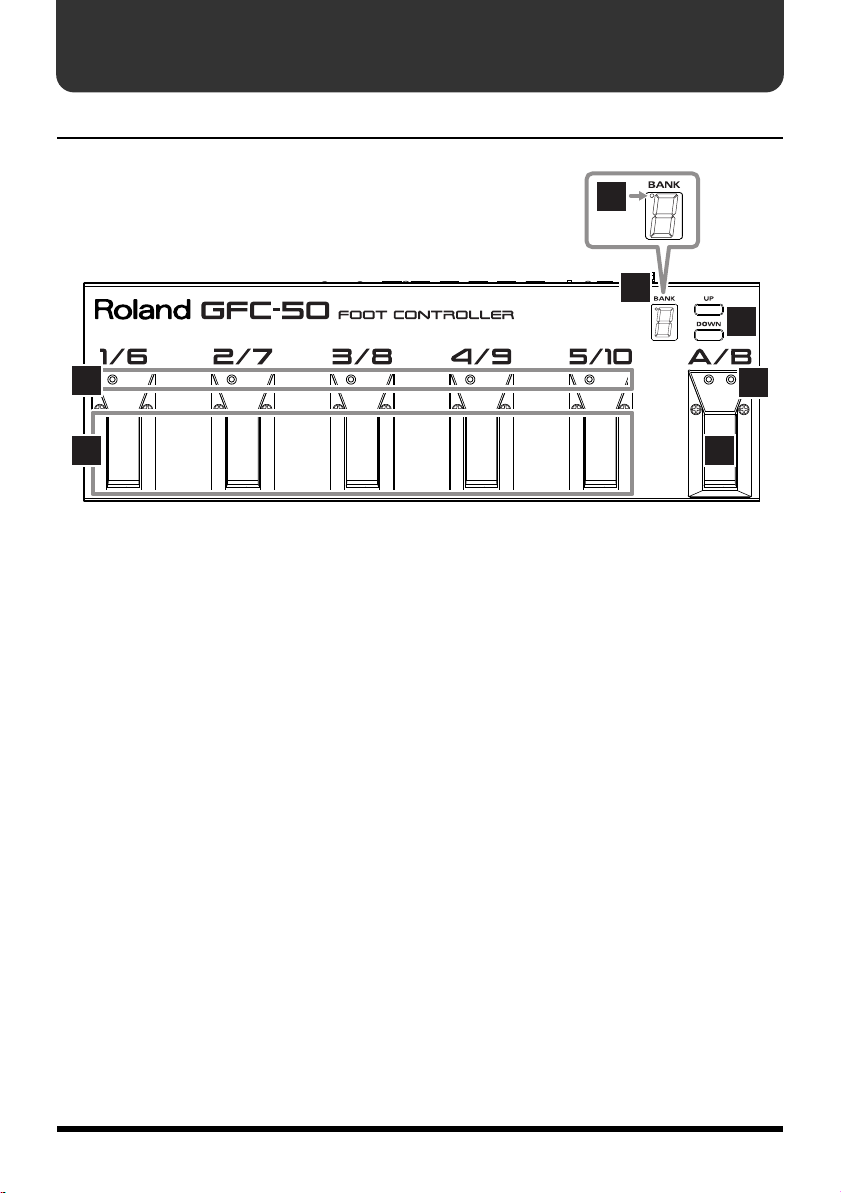
PANEL DESCRIPTIONS
Front Panel
fig.01
6
5
7
2
1 3
1.
Number Pedals
2.
Number Indicators
3.
Number Shift Pedal
4.
Number Shift Indicators (A/B)
5.
BANK Display
6.
Dot
7.
Bank Shift Buttons (UP/DOWN)
4
6
Page 7

Rear Panel
fig.02
PANEL DESCRIPTIONS
8 9
8.
Cord Hook
9.
AC Adaptor Jack
10.
POWER Switch
11.
BANK SHIFT Jacks (UP/DOWN)
12.
CTL (Control Pedal) Jacks (1/2)
13.
EXP (Expression Pedal) Jacks (1/2)➔ p. 12
14.
FOOT CONTROLLER OUT Connector
11 12 13
10 14
➔
➔
p. 10
p. 12
7
Page 8

CONNECTIONS
fig.03
fig.04
Connection to another
MIDI device
MIDI IN
FOOT CONTROLLER OUT
(MIDI OUT)
MIDI Cable
(optional)
AC Adaptor
PSA-Series
To prevent malfunction and/or damage to speakers or other devices, always
turn down the volume, and turn off the power on all devices before making
any connections.
If there are batteries in the unit while an AC adaptor is being used, normal
operation will continue should the line voltage be interrupted (power
blackout or power cord disconnection).
To prevent the inadvertent disruption of power to your unit (should the
plug be pulled out accidentally), and to avoid applying undue stress to the
AC adaptor jack, anchor the power cord using the cord hook, as shown in
the illustration.
8
Page 9

POWER ON
Once the connections have been completed (p. 8), turn on power to your
various devices in the order specified. By turning on devices in the wrong
order, you risk causing malfunction and/or damage to speakers and other
devices.
Ensure that all connections are correct and secure. Turn the GFC-50’s Power switch to
fig.05
■
the ON or ECONOMY position. Turn on the other devices.
About the Economy Mode
When the GFC-50 is being operated with batteries, the Economy mode can be used to
effectively extend battery life by about twice as long as usual.
The Bank Display may become somewhat dimmer and it may flicker a little, but this is
not an indication of a problem.
* The default MIDI channel of the GFC-50 is channel 1. Refer to “CHANGING MIDI
CHANNEL” (p. 13) if you want to change the default setting.
9
Page 10

PROGRAM CHANGE NUMBERS
A Program Change number is selected using the “Bank” button and “Number” pedals.
The Program Change message is transmitted the moment the Bank Shift button or
Number pedal is pressed.
Changing Banks
Pressing a Bank Shift button (UP or DOWN) changes Bank numbers in sequence (0 to
fig.06
12). The Bank Display shows the Bank Number currently selected.
Display
Banks 0 1 2
10 11 12
* When Bank 10, 11 or 12 is selected, the Dot in the upper left hand corner of the display will light.
fig.07
Banks
Program
Change Number
You can change Bank numbers using a pedal by connecting a foot switch (BOSS
FS-5U: optional) to the BANK SHIFT Jacks (UP/DOWN) on the rear of the GFC-50.
* When using the FS-5U, set the polarity switch as shown below.
fig.07a
0 1 2 10 11 12
0
10 20 100 110 120
Polarity switch
Changing Numbers
Using the Number Shift (A/B) Pedal and the Number Pedals, you can select numbers 1 to 10.
Numbers 1 to 10 correspond to Program Change numbers 1 to 10 respectively. By selecting A
Bank numbers 0 to 12 correspond to Program Change numbers as indicated in the following:
fig.08
or B with the Number Shift Pedal, you can select numbers 1 to 5 or 6 to 10 as shown below.
1/6 2/7 3/8 4/9 5/10
A
12345
B678910
10
With the Number Indicators and Number Shift Indicators, you can determine what
number is currently set.
Page 11

PROGRAM CHANGE NUMBERS
Setting a Program Change Number
Example 1:
Setting Program Change number 8.
fig.09
Example 2:
fig.10
0 (Bank: 0) + 8 (Number) = 8
Setting Program Change number 12.
10 (Bank: 1) + 2 (Number) = 12
Example 3:
Setting Program Change number 120.
110 (Bank: 11) + 10 (Number) = 120
fig.11
* The highest Program Change number is 128. Setting a number higher than 128 will cause the
Pedal Indicators to flash, indicating that no Program Change message is being transmitted.
11
Page 12

CONTROL CHANGE MESSAGES
The GFC-50 can accept connection of a maximum of two external expression pedals
(Roland EV-5: optional) and two foot switches (BOSS FS-5L/FS-5U: optional). This allows
you to control a connected MIDI instrument in real time with Control Change messages.
The Control Change jacks on the rear of the GFC-50 correspond to the following
Control Change numbers:
Expression Pedal
EXP 1: Volume (#7)
EXP 2: General Purpose Controller (#16)
Control Peal
CTL 1: Hold (#64)
CTL 2: General Purpose Controller (#80)
* “#” represents a Control Change number.
fig.12
Set the polarity switch
as shown below.
Foot switch
FS-5L (BOSS)
or
FS-5U (BOSS)
Expression Pedal
EV-5 (Roland)
* Either a latch-type (FS-5L), or momentary-type (FS-5U) footswitch can be connected to each CTL Jack.
Latch Type:
Momentary Type:
Pressing the pedal turns a connected unit (or function) ON or OFF.
Only while the pedal is being pressed, the ON/OFF status can be changed.
Use only the specified expression pedal (EV-5; sold separately).
By connecting any other expression pedals, you risk causing malfunction
and/or damage to the unit.
12
Page 13

CHANGING MIDI CHANNEL
The GFC-50’s default MIDI channel is channel 1. If you wish to change the default
channel, follow this procedure:
* The MIDI channel you set will not be stored in memory. It will be necessary to set the MIDI
channel each time the unit is turned on.
1.
Switch on the unit while holding the Number Shift Pedal (A/B) down.
2.
Select the desired MIDI channel using the Bank Shift Buttons (UP/DOWN).
(The Bank Display shows the MIDI channel currently selected.)
fig.13
Display
MIDI CHANNEL
* When any of MIDI channels 10 to 16 is selected, the Dot in the upper left hand corner of the
display will light.
3.
Press the Number Shift Pedal (A/B). (The MIDI channel has now been set.)
123 10 11 12 16
13
Page 14

BATTERY REPLACEMENT
When to replace the batteries
When operating on battery power only, the unit’s indicator will become flash
when battery power gets too low. Replace the battery as soon as possible.
* Even if the unit is set to ON, it will automatically switch to the ECONOMY mode when the
indicators begin to flash. The indicators will continue to flash until the batteries are replaced.
How to replace batteries
fig.14
* Do not mix new batteries with used ones. Do not mix batteries of different types (e.g., carbon
and alkaline).
* Be sure to insert the batteries correctly (ensure correct polarity).
14
Page 15

MIDI IMPLEMENTATION
FOOT CONTROLLER Date: Oct. 1, 2000
Model: GFC-50 Version: 1.00
1. TRANSMITTED DATA
●
Control change
Status
BnH ccH vvH
n = MIDI channel number 0H - FH (ch.1 - ch.16)
cc = Control number 07H, 10H, 40H, 50H (7, 16, 64, 80)
vv = Control Value 00H - 7FH (Prog.1 - Prog.128)
This message can be transmitted when the external pedal is connected.
●
Program change
Status
CnH ppH
n = MIDI channel number 0H - FH (ch.1 - ch.16)
pp = Program number 00H - 7FH (Prog.1 - Prog.128)
This message is transmitted when the patch of GFC-50 is changed.
Second Third
Second
15
Page 16

Version : 1.00
Date : Oct. 1, 2000
General purpose controller *1
Hold *1
Volume *1
General purpose controller *1
16
X
X
X
X
Transmitted Recognized Remarks
Default
Messages
Mode
**************
X
**************
Altered
True Voice
Note
Number :
1
MIDI Implementation Chart
Function...
Model GFC-50
FOOT CONTROLLER
1–16XX
Default
Changed
Basic
Channel
X
X XX
X
X
Note ON
Note OFF
Velocity
X
X
X
Key's
Ch's
After
Touch
XXX
X
X
O EXP1
O EXP2
7
166480
Pitch Bend
X
O CTL1
O CTL2
Control
Change
Page 17

Program Change Number 1–128
X : No
O : Yes
X
O
0–127
: True #
Prog
Change
X
XXX
X
XXX
: Song Pos
: Song Sel
: Tune
System Exclusive
System
Common
X
X
X
X
: Clock
: Command
System
Real Time
XXXXX
XXXXX
Local ON/OFF
: All sound off
:
: All Notes OFF
: Active Sense
: Reset
Aux
Message
* 1 Can be transmitted when the external pedal is connected.
Notes
Mode 2 : OMNI ON, MONO
Mode 4 : OMNI OFF, MONO
Mode 1 : OMNI ON, POLY
Mode 3 : OMNI OFF, POLY
17
Page 18

SPECIFICATIONS
GFC-50: Foot Controller
Controls
Pedal x 6
Bank Shift Buttons (UP/DOWN)
Power Switch
Display
Bank Display (7 segment)
Indicators
Number Indicators x 5
Number Shift Indicators (A/B)
Connectors
FOOT CONTROLLER OUT Connector
BANK SHIFT Jacks (UP/DOWN)
CTL (Control Pedal) Jacks (1/2)
EXP (Expression Pedal) Jacks (1/2)
AC Adaptor Jack
Power
DC 9V: AC Adaptor (PSA series)/
1.5V R6/LR6 (AA) type x 6 (optional)
Power Consumption
(under normal conditions)
40 mA (in the “ON” mode)
28 mA (in the “ECONOMY” mode)
*
Expected battery life under continuous
use:
Carbon:
15 hours or greater (in the “ON” mode)
30 hours or greater
(in the “ECONOMY” mode)
Alkaline:
40 hours or greater (in the “ON” mode)
80 hours or greater
(in the “ECONOMY” mode)
These figures will vary depending on the
actual conditions of use.
Dimensions
423 (W) x 135 (D) x 40 (H) mm
16-11/16 (W) x 5-3/8 (D) x 1-5/8 (H) inches
Weight
1.6 kg/3 lbs 9 oz (excluding AC adaptor)
Accessories
Owner’s Manual
AC Adaptor (PSA series)
Options
Foot Switch:
FS-5U (BOSS)
FS-5L (BOSS)
Expression Pedal:
EV-5 (Roland)
In the interest of product improvement, the
specifications and/or appearance of this unit
are subject to change without prior notice.
18
Page 19

For EU Countries
For EU Countries
This product complies with the requirements of EMC Directive 2004/108/EC.
For the USA
FEDERAL COMMUNICATIONS COMMISSION
RADIO FREQUENCY INTERFERENCE STATEMENT
This equipment has been tested and found to comply with the limits for a Class B digital device, pursuant to Part 15 of the
FCC Rules. These limits are designed to provide reasonable protection against harmful interference in a residential
installation. This equipment generates, uses, and can radiate radio frequency energy and, if not installed and used in
accordance with the instructions, may cause harmful interference to radio communications. However, there is no guarantee
that interference will not occur in a particular installation. If this equipment does cause harmful interference to radio or
television reception, which can be determined by turning the equipment off and on, the user is encouraged to try to correct the
interference by one or more of the following measures:
– Reorient or relocate the receiving antenna.
– Increase the separation between the equipment and receiver.
– Connect the equipment into an outlet on a circuit different from that to which the receiver is connected.
– Consult the dealer or an experienced radio/TV technician for help.
This device complies with Part 15 of the FCC Rules. Operation is subject to the following two conditions:
(1) this device may not cause harmful interference, and
(2) this device must accept any interference received, including interference that may cause undesired operation.
Unauthorized changes or modification to this system can void the users authority to operate this equipment.
This equipment requires shielded interface cables in order to meet FCC class B Limit.
For Canada
NOTICE
This Class B digital apparatus meets all requirements of the Canadian Interference-Causing Equipment Regulations.
AVIS
Cet appareil numérique de la classe B respecte toutes les exigences du Règlement sur le matériel brouilleur du Canada.
19
Page 20

Information
AFRICA
EGYPT
Al Fanny Trading Office
9, EBN Hagar Al Askalany
Street,
ARD E1 Golf, Heliopolis,
Cairo 11341, EGYPT
TEL: (022)-418-5531
REUNION
Maison FO - YAM Marcel
25 Rue Jules Hermann,
Chaudron - BP79 97 491
Ste Clotilde Cedex,
REUNION ISLAND
TEL: (0262) 218-429
SOUTH AFRICA
T.O.M.S. Sound & Music
(Pty)Ltd.
2 ASTRON ROAD DENVER
JOHANNESBURG ZA 2195,
SOUTH AFRICA
TEL: (011)417 3400
Paul Bothner(PTY)Ltd.
Royal Cape Park, Unit 24
Londonderry Road, Ottery 7800
Cape Town, SOUTH AFRICA
TEL: (021) 799 4900
ASIA
CHINA
Roland Shanghai Electronics
Co.,Ltd.
5F. No.1500 Pingliang Road
Shanghai 200090, CHINA
TEL: (021) 5580-0800
Roland Shanghai Electronics
Co.,Ltd.
(BEIJING OFFICE)
10F. No.18 3 Section Anhuaxili
Chaoyang District Beijing
100011 CHINA
TEL: (010) 6426-5050
HONG KONG
Tom Lee Music Co., Ltd.
Service Division
22-32 Pun Shan Street, Tsuen
Wan, New Territories,
HONG KONG
TEL: 2415 0911
Parsons Music Ltd.
8th Floor, Railway Plaza, 39
Chatham Road South, T.S.T,
Kowloon, HONG KONG
TEL: 2333 1863
INDIA
Rivera Digitec (India) Pvt. Ltd.
411, Nirman Kendra
Mahalaxmi Flats Compound
Off. Dr. Edwin Moses Road,
Mumbai-400011, INDIA
TEL: (022) 2493 9051
INDONESIA
PT Citra IntiRama
Jl. Cideng Timur No. 15J-15O
Jakarta Pusat
INDONESIA
TEL: (021) 6324170
KOREA
Cosmos Corporation
1461-9, Seocho-Dong,
Seocho Ku, Seoul, KOREA
TEL: (02) 3486-8855
MALAYSIA
Roland Asia Pacific Sdn. Bhd.
45-1, Block C2, Jalan PJU 1/39,
Dataran Prima, 47301 Petaling
Jaya, Selangor, MALAYSIA
TEL: (03) 7805-3263
VIET NAM
Suoi Nhac Company, Ltd
370 Cach Mang Thang Tam St.
Dist.3, Ho Chi Minh City,
VIET NAM
TEL: 9316540
When you need repair service, call your nearest Roland Service Center or authorized Roland
distributor in your country as shown below.
PHILIPPINES
G.A. Yupangco & Co. Inc.
339 Gil J. Puyat Avenue
Makati, Metro Manila 1200,
PHILIPPINES
TEL: (02) 899 9801
SINGAPORE
SWEE LEE MUSIC
COMPANY PTE. LTD.
150 Sims Drive,
SINGAPORE 387381
TEL: 6846-3676
TAIWAN
ROLAND TAIWAN
ENTERPRISE CO., LTD.
Room 5, 9fl. No. 112 Chung
Shan N.Road Sec.2, Taipei,
TAIWAN, R.O.C.
TEL: (02) 2561 3339
THAILAND
Theera Music Co. , Ltd.
100-108 Soi Verng
Nakornkasem, New
Road,Sumpantawongse,
Bangkok 10100 THAILAND
TEL: (02) 224-8821
AUSTRALIA/
NEW ZEALAND
AUSTRALIA/
NEW ZEALAND
Roland Corporation
Australia Pty.,Ltd.
38 Campbell Avenue
Dee Why West. NSW 2099
AUSTRALIA
For Australia
Tel: (02) 9982 8266
For New Zealand
Tel: (09) 3098 715
CENTRAL/LATIN
AMERICA
ARGENTINA
Instrumentos Musicales S.A.
Av.Santa Fe 2055
(1123) Buenos Aires
ARGENTINA
TEL: (011) 4508-2700
BARBADOS
A&B Music Supplies LTD
12 Webster Industrial Park
Wildey, St.Michael, Barbados
TEL: (246)430-1100
BRAZIL
Roland Brasil Ltda.
Rua San Jose, 780 Sala B
Parque Industrial San Jose
Cotia - Sao Paulo - SP, BRAZIL
TEL: (011) 4615 5666
CHILE
Comercial Fancy II S.A.
Rut.: 96.919.420-1
Nataniel Cox #739, 4th Floor
Santiago - Centro, CHILE
TEL: (02) 688-9540
COLOMBIA
Centro Musical Ltda.
Cra 43 B No 25 A 41 Bododega 9
Medellin, Colombia
TEL: (574)3812529
COSTA RICA
JUAN Bansbach Instrumentos
Musicales
Ave.1. Calle 11, Apartado
10237,
San Jose, COSTA RICA
TEL: 258-0211
CURACAO
Zeelandia Music Center Inc.
Orionweg 30
Curacao, Netherland Antilles
TEL:(305)5926866
DOMINICAN REPUBLIC
Instrumentos Fernando Giraldez
Calle Proyecto Central No.3
Ens.La Esperilla
Santo Domingo,
Dominican Republic
TEL:(809) 683 0305
ECUADOR
Mas Musika
Rumichaca 822 y Zaruma
Guayaquil - Ecuador
TEL:(593-4)2302364
EL SALVADOR
OMNI MUSIC
75 Avenida Norte y Final
Alameda Juan Pablo II,
Edificio No.4010 San Salvador,
EL SALVADOR
TEL: 262-0788
GUATEMALA
Casa Instrumental
Calzada Roosevelt 34-01,zona 11
Ciudad de Guatemala
Guatemala
TEL:(502) 599-2888
HONDURAS
Almacen Pajaro Azul S.A. de C.V.
BO.Paz Barahona
3 Ave.11 Calle S.O
San Pedro Sula, Honduras
TEL: (504) 553-2029
MARTINIQUE
Musique & Son
Z.I.Les Mangle
97232 Le Lamantin
Martinique F.W.I.
TEL: 596 596 426860
Gigamusic SARL
10 Rte De La Folie
97200 Fort De France
Martinique F.W.I.
TEL: 596 596 715222
MEXICO
Casa Veerkamp, s.a. de c.v.
Av. Toluca No. 323, Col. Olivar
de los Padres 01780 Mexico
D.F. MEXICO
TEL: (55) 5668-6699
NICARAGUA
Bansbach Instrumentos
Musicales Nicaragua
Altamira D'Este Calle Principal
de la Farmacia 5ta.Avenida
1 Cuadra al Lago.#503
Managua, Nicaragua
TEL: (505)277-2557
PANAMA
SUPRO MUNDIAL, S.A.
Boulevard Andrews, Albrook,
Panama City, REP. DE
PANAMA
TEL: 315-0101
PARAGUAY
Distribuidora De
Instrumentos Musicales
J.E. Olear y ESQ. Manduvira
Asuncion PARAGUAY
TEL: (595) 21 492147
PERU
Audionet
Distribuciones Musicales SAC
Juan Fanning 530
Miraflores
Lima - Peru
TEL: (511) 4461388
TRINIDAD
AMR Ltd
Ground Floor
Maritime Plaza
Barataria Trinidad W.I.
TEL: (868) 638 6385
URUGUAY
Todo Musica S.A.
Francisco Acuna de Figueroa
1771
C.P.: 11.800
Montevideo, URUGUAY
TEL: (02) 924-2335
VENEZUELA
Instrumentos Musicales
Allegro,C.A.
Av.las industrias edf.Guitar
import
#7 zona Industrial de Turumo
Caracas, Venezuela
TEL: (212) 244-1122
EUROPE
AUSTRIA
Roland Elektronische
Musikinstrumente HmbH.
Austrian Office
Eduard-Bodem-Gasse 8,
A-6020 Innsbruck, AUSTRIA
TEL: (0512) 26 44 260
BELGIUM/FRANCE/
HOLLAND/
LUXEMBOURG
Roland Central Europe N.V.
Houtstraat 3, B-2260, Oevel
(Westerlo) BELGIUM
TEL: (014) 575811
CROATIA
ART-CENTAR
Degenova 3.
HR - 10000 Zagreb
TEL: (1) 466 8493
CZECH REP.
CZECH REPUBLIC
DISTRIBUTOR s.r.o
Voctárova 247/16
CZ - 180 00 PRAHA 8,
CZECH REP.
TEL: (2) 830 20270
DENMARK
Roland Scandinavia A/S
Nordhavnsvej 7, Postbox 880,
DK-2100 Copenhagen
DENMARK
TEL: 3916 6200
FINLAND
Roland Scandinavia As, Filial
Finland
Elannontie 5
FIN-01510 Vantaa, FINLAND
TEL: (0)9 68 24 020
GERMANY
Roland Elektronische
Musikinstrumente HmbH.
Oststrasse 96, 22844
Norderstedt, GERMANY
TEL: (040) 52 60090
GREECE/CYPRUS
STOLLAS S.A.
Music Sound Light
155, New National Road
Patras 26442, GREECE
TEL: 2610 435400
HUNGARY
Roland East Europe Ltd.
Warehouse Area ‘DEPO’ Pf.83
H-2046 Torokbalint,
HUNGARY
TEL: (23) 511011
IRELAND
Roland Ireland
G2 Calmount Park, Calmount
Avenue, Dublin 12
Republic of IRELAND
TEL: (01) 4294444
ITALY
Roland Italy S. p. A.
Viale delle Industrie 8,
20020 Arese, Milano, ITALY
TEL: (02) 937-78300
NORWAY
Roland Scandinavia Avd.
Kontor Norge
Lilleakerveien 2 Postboks 95
Lilleaker N-0216 Oslo
NORWAY
TEL: 2273 0074
POLAND
ROLAND POLSKA SP. Z O.O.
UL. Gibraltarska 4.
PL-03 664 Warszawa
POLAND
TEL: (022) 679 4419
PORTUGAL
Roland Iberia, S.L.
Portugal Office
Cais das Pedras, 8/9-1 Dto
4050-465, Porto, PORTUGAL
TEL: 22 608 00 60
ROMANIA
FBS LINES
Piata Libertatii 1,
535500 Gheorgheni,
ROMANIA
TEL: (266) 364 609
RUSSIA
MuTek
Dorozhnaya ul.3,korp.6
117 545 Moscow, RUSSIA
TEL: (095) 981-4967
SLOVAKIA
DAN Acoustic s.r.o.
Povazská 18.
SK - 940 01 Nové Zámky
TEL: (035) 6424 330
SPAIN
Roland Iberia, S.L.
Paseo García Faria, 33-35
08005 Barcelona SPAIN
TEL: 93 493 91 00
SWEDEN
Roland Scandinavia A/S
SWEDISH SALES OFFICE
Danvik Center 28, 2 tr.
S-131 30 Nacka SWEDEN
TEL: (0)8 702 00 20
SWITZERLAND
Roland (Switzerland) AG
Landstrasse 5, Postfach,
CH-4452 Itingen,
SWITZERLAND
TEL: (061) 927-8383
UKRAINE
EURHYTHMICS Ltd.
P.O.Box: 37-a.
Nedecey Str. 30
UA - 89600 Mukachevo,
UKRAINE
TEL: (03131) 414-40
UNITED KINGDOM
Roland (U.K.) Ltd.
Atlantic Close, Swansea
Enterprise Park, SWANSEA
SA7 9FJ,
UNITED KINGDOM
TEL: (01792) 702701
MIDDLE EAST
BAHRAIN
Moon Stores
No.1231&1249 Rumaytha
Building Road 3931, Manama
339 BAHRAIN
TEL: 17 813 942
IRAN
MOCO INC.
No.41 Nike St., Dr.Shariyati Ave.,
Roberoye Cerahe Mirdamad
Tehran, IRAN
TEL: (021)-2285-4169
ISRAEL
Halilit P. Greenspoon & Sons
Ltd.
8 Retzif Ha'alia Hashnia St.
Tel-Aviv-Yafo ISRAEL
TEL: (03) 6823666
JORDAN
MUSIC HOUSE CO. LTD.
FREDDY FOR MUSIC
P. O. Box 922846
Amman 11192 JORDAN
TEL: (06) 5692696
KUWAIT
EASA HUSAIN AL-YOUSIFI
& SONS CO.
Al-Yousifi Service Center
P.O.Box 126 (Safat) 13002
KUWAIT
TEL: 00 965 802929
LEBANON
Chahine S.A.L.
George Zeidan St., Chahine
Bldg., Achrafieh, P.O.Box: 165857
Beirut, LEBANON
TEL: (01) 20-1441
OMAN
TALENTZ CENTRE L.L.C.
Malatan House No.1
Al Noor Street, Ruwi
SULTANATE OF OMAN
TEL: 2478 3443
QATAR
Al Emadi Co. (Badie Studio &
Stores)
P.O. Box 62, Doha, QATAR
TEL: 4423-554
SAUDI ARABIA
aDawliah Universal
Electronics APL
Behind Pizza Inn
Prince Turkey Street
aDawliah Building,
PO BOX 2154,
Alkhobar 31952
SAUDI ARABIA
TEL: (03) 8643601
SYRIA
Technical Light & Sound
Center
Rawda, Abdul Qader Jazairi St.
Bldg. No. 21, P.O.BOX 13520,
Damascus, SYRIA
TEL: (011) 223-5384
TURKEY
ZUHAL DIS TICARET A.S.
Galip Dede Cad. No.37
Beyoglu - Istanbul / TURKEY
TEL: (0212) 249 85 10
U.A.E.
Zak Electronics & Musical
Instruments Co. L.L.C.
Zabeel Road, Al Sherooq Bldg.,
No. 14, Ground Floor, Dubai,
U.A.E.
TEL: (04) 3360715
NORTH AMERICA
CANADA
Roland Canada Ltd.
(Head Office)
5480 Parkwood Way
Richmond B. C., V6V 2M4
CANADA
TEL: (604) 270 6626
Roland Canada Ltd.
(Toronto Office)
170 Admiral Boulevard
Mississauga On L5T 2N6
CANADA
TEL: (905) 362 9707
U. S. A.
Roland Corporation U.S.
5100 S. Eastern Avenue
Los Angeles, CA 90040-2938,
U. S. A.
TEL: (323) 890 3700
As of Oct. 1, 2007 (ROLAND)
 Loading...