

Page 1
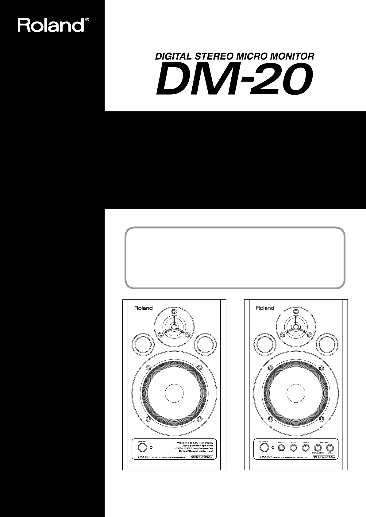
201b
Before using this unit, carefully read the sections entitled: “IMPORTANT
SAFETY INSTRUCTIONS” (p. 2), “USING THE UNIT SAFELY” (pp. 3–4), and
“IMPORTANT NOTES” (p. 6). These sections provide important information
concerning the proper operation of the unit. Additionally, in order to feel
assured that you have gained a good grasp of every feature provided by your
new unit, Owner’s manual should be read in its entirety. The manual should be
saved and kept on hand as a convenient reference.
Owner’s Manual
Bedienungsanleitung
Mode d’emploi
Manuale d’uso
Manual del usuario
202
Copyright © 2004 ROLAND CORPORATION
All rights reserved. No part of this publication may be reproduced in any form without the
written permission of ROLAND CORPORATION.
Page 2
CAUTION
RISK OF ELECTRIC SHOCK
DO NOT OPEN
ATTENTION: RISQUE DE CHOC ELECTRIQUE NE PAS OUVRIR
CAUTION: TO REDUCE THE RISK OF ELECTRIC SHOCK,
DO NOT REMOVE COVER (OR BACK).
NO USER-SERVICEABLE PARTS INSIDE.
REFER SERVICING TO QUALIFIED SERVICE PERSONNEL.
The lightning flash with arrowhead symbol, within an
equilateral triangle, is intended to alert the user to the
presence of uninsulated “dangerous voltage” within the
product’s enclosure that may be of sufficient magnitude to
constitute a risk of electric shock to persons.
The exclamation point within an equilateral triangle is
intended to alert the user to the presence of important
operating and maintenance (servicing) instructions in the
literature accompanying the product.
INSTRUCTIONS PERTAINING TO A RISK OF FIRE, ELECTRIC SHOCK, OR INJURY TO PERSONS.
IMPORTANT SAFETY INSTRUCTIONS
SAVE THESE INSTRUCTIONS
WARNING - When using electric products, basic precautions should always be followed, including the following:
1. Read these instructions.
2. Keep these instructions.
3. Heed all warnings.
4. Follow all instructions.
5. Do not use this apparatus near water.
6. Clean only with a dry cloth.
7. Do not block any of the ventilation openings. Install in
accordance with the manufacturers instructions.
8. Do not install near any heat sources such as radiators,
heat registers, stoves, or other apparatus (including
amplifiers) that produce heat.
9. Do not defeat the safety purpose of the polarized or
grounding-type plug. A polarized plug has two blades with
one wider than the other. A grounding type plug has two
blades and a third grounding prong. The wide blade or the
third prong are provided for your safety. When the provided
plug does not fit into your outlet, consult an electrician for
replacement of the obsolete outlet.
IMPORTANT: THE WIRES IN THIS MAINS LEAD ARE COLOURED IN ACCORDANCE WITH THE FOLLOWING CODE.
BLUE:
BROWN:
As the colours of the wires in the mains lead of this apparatus may not correspond with the coloured markings identifying
the terminals in your plug, proceed as follows:
The wire which is coloured BLUE must be connected to the terminal which is marked with the letter N or coloured BLACK.
The wire which is coloured BROWN must be connected to the terminal which is marked with the letter L or coloured RED.
Under no circumstances must either of the above wires be connected to the earth terminal of a three pin plug.
NEUTRAL
LIVE
10. Protect the power cord from being walked on or pinched
particularly at plugs, convenience receptacles, and the
point where they exit from the apparatus.
11. Only use attachments/accessories specified by the
manufacturer.
12. Never use with a cart, stand, tripod, bracket,
or table except as specified by the
manufacturer, or sold with the apparatus.
When a cart is used, use caution when
moving the cart/apparatus combination to
avoid injury from tip-over.
13. Unplug this apparatus during lightning storms or when
unused for long periods of time.
14. Refer all servicing to qualified service personnel. Servicing
is required when the apparatus has been damaged in any
way, such as power-supply cord or plug is damaged, liquid
has been spilled or objects have fallen into the apparatus,
the apparatus has been exposed to rain or moisture, does
not operate normally, or has been dropped.
For the U.K.
2
Page 3
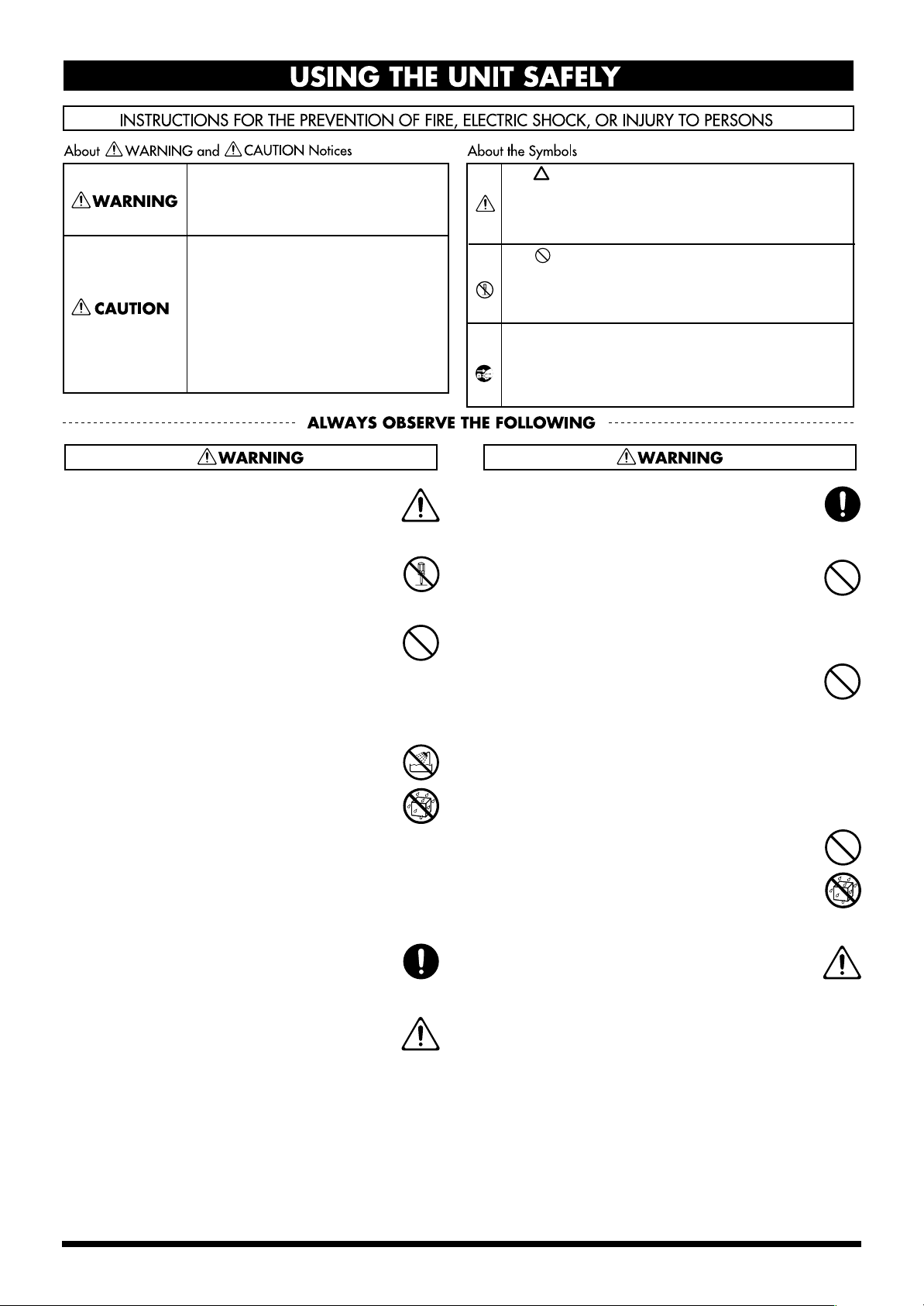
USING THE UNIT SAFELY
Used for instructions intended to alert
the user to the risk of death or severe
injury should the unit be used
improperly.
Used for instructions intended to alert
the user to the risk of injury or material
damage should the unit be used
improperly.
* Material damage refers to damage or
other adverse effects caused with
respect to the home and all its
furnishings, as well to domestic
animals or pets.
001
• Before using this unit, make sure to read the instructions
below, and the Owner’s Manual.
..........................................................................................................
002a
• Do not open or perform any internal modifications on
the unit.
..........................................................................................................
003
• Do not attempt to repair the unit, or replace parts within
it (except when this manual provides specific instructions directing you to do so). Refer all servicing to your
retailer, the nearest Roland Service Center, or an authorized Roland distributor, as listed on the “Information”
page.
..........................................................................................................
004
• Never use or store the unit in places that are:
• Subject to temperature extremes (e.g., direct sunlight
in an enclosed vehicle, near a heating duct, on top of
heat-generating equipment); or are
• Damp (e.g., baths, washrooms, on wet floors); or are
• Humid; or are
• Exposed to rain; or are
• Dusty; or are
• Subject to high levels of vibration.
The symbol alerts the user to important instructions
or warnings.The specific meaning of the symbol is
determined by the design contained within the
triangle. In the case of the symbol at left, it is used for
general cautions, warnings, or alerts to danger.
The symbol alerts the user to items that must never
be carried out (are forbidden). The specific thing that
must not be done is indicated by the design contained
within the circle. In the case of the symbol at left, it
means that the unit must never be disassembled.
The ● symbol alerts the user to things that must be
carried out. The specific thing that must be done is
indicated by the design contained within the circle. In
the case of the symbol at left, it means that the powercord plug must be unplugged from the outlet.
008e
• Use only the attached power-supply cord. Also, the
supplied power cord must not be used with any other
device.
..........................................................................................................
009
• Do not excessively twist or bend the power cord, nor
place heavy objects on it. Doing so can damage the cord,
producing severed elements and short circuits.
Damaged cords are fire and shock hazards!
..........................................................................................................
010
• This unit, either alone or in combination with an
amplifier and headphones or speakers, may be capable
of producing sound levels that could cause permanent
hearing loss. Do not operate for a long period of time at a
high volume level, or at a level that is uncomfortable. If
you experience any hearing loss or ringing in the ears,
you should immediately stop using the unit, and consult
an audiologist.
..........................................................................................................
011
• Do not allow any objects (e.g., flammable material, coins,
pins); or liquids of any kind (water, soft drinks, etc.) to
penetrate the unit.
..........................................................................................................
007
• Make sure you always have the unit placed so it is level
and sure to remain stable. Never place it on stands that
could wobble, or on inclined surfaces.
..........................................................................................................
008a
• The unit should be connected to a power supply only of
the type described in the operating instructions, or as
marked on the rear side of unit.
..........................................................................................................
..........................................................................................................
012a:
• Immediately turn the power off, remove the power cord
from the outlet, and request servicing by your retailer,
the nearest Roland Service Center, or an authorized
Roland distributor, as listed on the “Information” page
when:
• The power-supply cord, or the plug has been damaged; or
• If smoke or unusual odor occurs
• Objects have fallen into, or liquid has been spilled onto the
unit; or
• The unit has been exposed to rain (or otherwise has become
wet); or
• The unit does not appear to operate normally or exhibits a
marked change in performance.
..........................................................................................................
3
Page 4
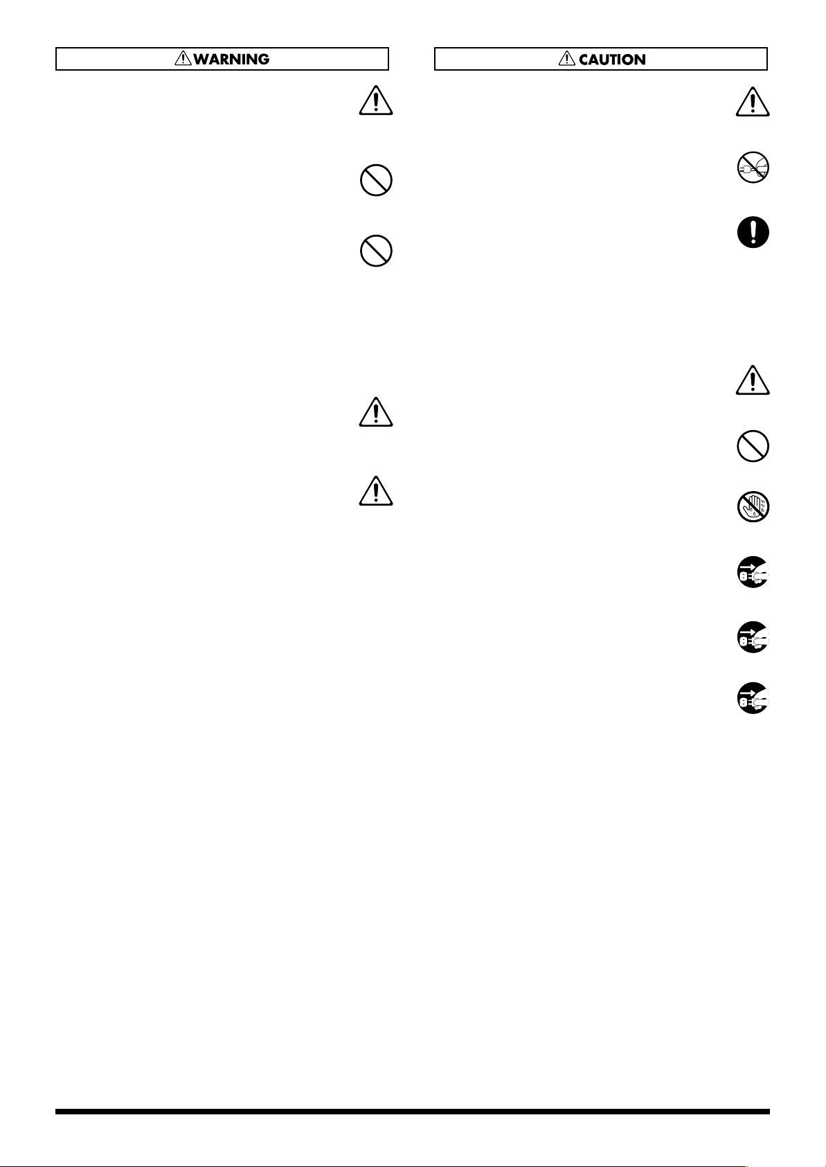
013
• In households with small children, an adult should
provide supervision until the child is capable of
following all the rules essential for the safe operation of
the unit.
..........................................................................................................
014
• Protect the unit from strong impact.
(Do not drop it!)
..........................................................................................................
015
• Do not force the unit’s power-supply cord to share an
outlet with an unreasonable number of other devices. Be
especially careful when using extension cords—the total
power used by all devices you have connected to the
extension cord’s outlet must never exceed the power
rating (watts/amperes) for the extension cord. Excessive
loads can cause the insulation on the cord to heat up
and eventually melt through.
..........................................................................................................
016
• Before using the unit in a foreign country, consult with
your retailer, the nearest Roland Service Center, or an
authorized Roland distributor, as listed on the “Information” page.
..........................................................................................................
026
• Do not put anything that contains water (e.g., flower
vases) on this unit. Also, avoid the use of insecticides,
perfumes, alcohol, nail polish, spray cans, etc., near the
unit. Swiftly wipe away any liquid that spills on the unit
using a dry, soft cloth.
..........................................................................................................
101a
• The unit should be located so that its location or position
does not interfere with its proper ventilation.
..........................................................................................................
102b
• Always grasp only the plug on the power-supply cord
when plugging into, or unplugging from, an outlet or
this unit.
..........................................................................................................
103a:
• At regular intervals, you should unplug the power plug
and clean it by using a dry cloth to wipe all dust and
other accumulations away from its prongs. Also,
disconnect the power plug from the power outlet
whenever the unit is to remain unused for an extended
period of time. Any accumulation of dust between the
power plug and the power outlet can result in poor
insulation and lead to fire.
..........................................................................................................
104
• Try to prevent cords and cables from becoming
entangled. Also, all cords and cables should be placed so
they are out of the reach of children.
..........................................................................................................
106
• Never climb on top of, nor place heavy objects on the
unit.
..........................................................................................................
107b
• Never handle the power cord or its plugs with wet
hands when plugging into, or unplugging from, an
outlet or this unit.
..........................................................................................................
108a
• Before moving the unit, disconnect the power plug from
the outlet, and pull out all cords from external devices.
..........................................................................................................
109a
• Before cleaning the unit, turn off the power and unplug
the power cord from the outlet.
..........................................................................................................
110a
• Whenever you suspect the possibility of lightning in
your area, pull the plug on the power cord out of the
outlet.
..........................................................................................................
4
Page 5
IMPORTANT NOTES
291b
In addition to the items listed under “IMPORTANT SAFETY INSTRUCTIONS” and “USING THE UNIT SAFELY” on pages
2–4, please read and observe the following:
Power Supply
301
• Do not connect this unit to same electrical outlet that is being
used by an electrical appliance that is controlled by an inverter
(such as a refrigerator, washing machine, microwave oven, or air
conditioner), or that contains a motor. Depending on the way in
which the electrical appliance is used, power supply noise may
cause this unit to malfunction or may produce audible noise. If it
is not practical to use a separate electrical outlet, connect a power
supply noise filter between this unit and the electrical outlet.
307
• Before connecting this unit to other devices, turn off the power
to all units. This will help prevent malfunctions and/or damage
to speakers or other devices.
308
• Although the LCD and LEDs are switched off when the POWER
switch is switched off, this does not mean that the unit has been
completely disconnected from the source of power. If you need
to turn off the power completely, first turn off the POWER
switch, then unplug the power cord from the power outlet. For
this reason, the outlet into which you choose to connect the
power cord’s plug should be one that is within easy reach.
Placement
351
• Using the unit near power amplifiers (or other equipment
containing large power transformers) may induce hum. To
alleviate the problem, change the orientation of this unit; or
move it farther away from the source of interference.
352a
• This device may interfere with radio and television reception. Do
not use this device in the vicinity of such receivers.
352b
• Noise may be produced if wireless communications devices,
such as cell phones, are operated in the vicinity of this unit. Such
noise could occur when receiving or initiating a call, or while
conversing. Should you experience such problems, you should
relocate such wireless devices so they are at a greater distance
from this unit, or switch them off.
354b
• Do not expose the unit to direct sunlight, place it near devices
that radiate heat, leave it inside an enclosed vehicle, or otherwise
subject it to temperature extremes. Also, do not allow lighting
devices that normally are used while their light source is very
close to the unit (such as a piano light), or powerful spotlights to
shine upon the same area of the unit for extended periods of
time. Excessive heat can deform or discolor the unit.
355b
• When moved from one location to another where the temperature and/or humidity is very different, water droplets (condensation) may form inside the unit. Damage or malfunction may
result if you attempt to use the unit in this condition. Therefore,
before using the unit, you must allow it to stand for several
hours, until the condensation has completely evaporated.
356
• Do not allow rubber, vinyl, or similar materials to remain on the
unit for long periods of time. Such objects can discolor or
otherwise harmfully affect the finish.
359
• Do not paste stickers, decals, or the like to this instrument.
Peeling such matter off the instrument may damage the exterior
finish.
Add
• Do not allow objects to remain on top of the unit while it is in
operation. Placing heavy objects on this unit may result in injury
if it overturns or falls.
Maintenance
401b
• To clean the unit, use a dry, soft cloth; or one that is slightly
dampened. Try to wipe the entire surface using an equal amount
of strength, moving the cloth along with the grain of the wood.
Rubbing too hard in the same area can damage the finish.
402
• Never use benzine, thinners, alcohol or solvents of any kind, to
avoid the possibility of discoloration and/or deformation.
Additional Precautions
553
• Use a reasonable amount of care when using the unit’s buttons,
sliders, or other controls; and when using its jacks and
connectors. Rough handling can lead to malfunctions.
556
• When connecting / disconnecting all cables, grasp the connector
itself—never pull on the cable. This way you will avoid causing
shorts, or damage to the cable’s internal elements.
557
•A small amount of heat will radiate from the unit during normal
operation.
558a
• To avoid disturbing your neighbors, try to keep the unit’s
volume at reasonable levels. You may prefer to use headphones,
so you do not need to be concerned about those around you
(especially when it is late at night).
559a
• When you need to transport the unit, package it in the box
(including padding) that it came in, if possible. Otherwise, you
will need to use equivalent packaging materials.
562
• Use a cable from Roland to make the connection. If using some
other make of connection cable, please note the following
precautions.
• Some connection cables contain resistors. Do not use cables
that incorporate resistors for connecting to this unit. The use
of such cables can cause the sound level to be extremely low,
or impossible to hear. For information on cable specifications,
contact the manufacturer of the cable.
Add
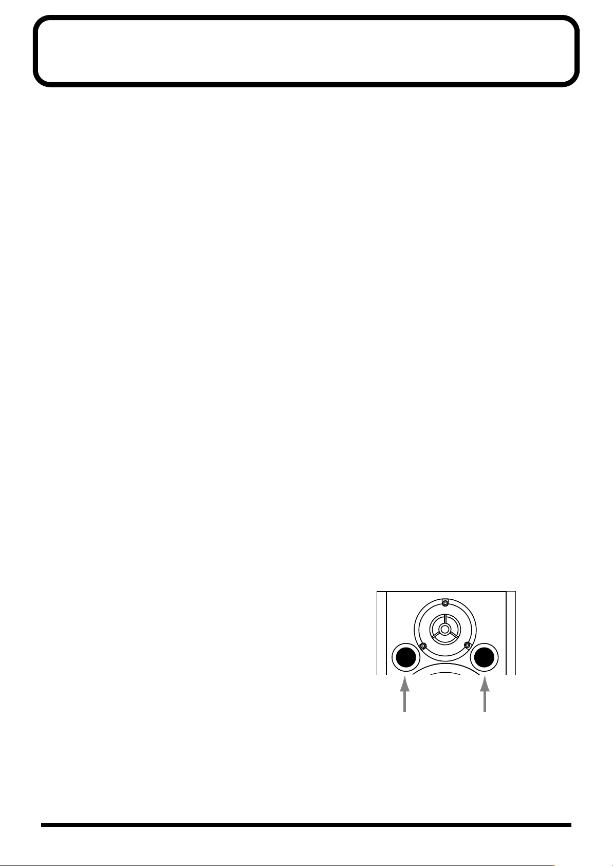
• Be sure to avoid inserting your fingers in the bass reflex ports
when transporting or moving the speakers, as your fingers may
become wedged and stuck in the ports.
5
Page 6
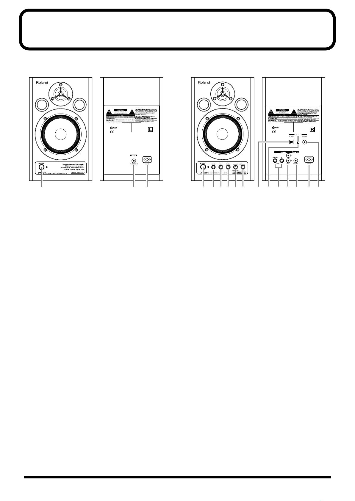
Panel Description
Left Channel
fig.2
1 2 3
Left Channel
1.
POWER Switch, POWER Indicator
This turns the power of the left (L) channel on/off. When
the power is on, the indicator located at the side of the
switch will light.
2.
L Channel Input Jack
Connect this to L Channel Output Jack 14 on the rightside unit. For the connection, use the included speaker
cable.
3.
AC Inlet
Connect the included Power cord here (p. 17). Plug it
firmly in, so that the cable does not accidentally become
disconnected.
Right Channel
4.
POWER Switch, POWER Indicator
This turns the power of the right (R) channel on/off.
When the power is on, the indicator located at the side of
the switch will light.
5.
PHONES Jack
When you connect headphones to this jack, no sound
will be heard from the speakers.
6.
BASS Control Knob
7.
TREBLE Control Knob
These adjust the tones of the bass and treble. Set to center
to make the tones flat.
Right Channel
fig.3
4 5 87 9121310 14 1511 1686
8.
VOLUME Knob (DIGITAL/LINE 1)
This adjusts the volume of devices connected to digital
input connectors 10, 16, and LINE 1 Input Jacks 13.
9.
VOLUME Knob (LINE 2)
This adjusts the volume of the device connected to LINE
2 Input Jacks 12.
10.
Digital Input Connector (Optical)
This is the digital input connector for optic-fiber cable.
11.
Digital Input Select Switch
This switch selects digital input connector 10 or 16 on
the rear panel. Select the connector used for the input
signal.
12.
LINE 2 Input Jacks (L (MONO), R) (1/4” phone type)
For mono input, use the L (MONO) jack.
13.
LINE 1 Input Jacks (L, R) (RCA phono type)
14.
L Channel Output Jack
Connect this to L Channel Input Jack 2 on the left-side
unit.
15.
AC Inlet
Connect the included Power cord here (p. 17). Plug it
firmly in, so that the cable does not accidentally become
disconnected.
16.
Digital Input Connector (Coaxial)
This is the digital input connector for coaxial cable.
6
Page 7

Connections
Attaching the Rubber Feet (Included)
Precautions When Connecting and Turning on the Power
921
• To prevent malfunction and/or damage to speakers or
other devices, always turn down the volume, and turn off
the power on all devices before making any connections.
926a
• When connection cables with resistors are used, the
volume level of equipment connected to the inputs (Input
Jucks) may be low. If this happens, use connection cables
that do not contain resistors, such as those from the
Roland PCS series.
941
• Once the connections have been completed, turn on
power to your various devices in the order specified. By
turning on devices in the wrong order, you risk causing
malfunction and/or damage to speakers and other
devices. (When turning the power off, reverse this
procedure.)
< Connected devices → DM-20 (R) → DM-20 (L) >
942
• This unit is equipped with a protection circuit. A brief
interval (a few seconds) after power up is required before
the unit will operate normally.
Connection Example
INPUT
(FROM RIGHT)
OUTPUT
(TO LEFT)
Rear Panel
Select
Sound Module, CD Player, MD Player, etc.
Español Italiano Français Deutsch English
7
Page 8

Bedienfeldbeschreibung
Linker Kanal
fig.2
1 2 3
Linker Kanal
1.
POWER-Schalter, POWER-Anzeige
Schaltet das Signal für den linken Kanal (L) ein/aus. Bei
eingeschaltetem Signal leuchtet die Anzeige an der
linken Seite des Schalters auf.
2.
L-Kanal-Eingangsbuchse
Verbinden Sie diese Buchse mit der L-KanalAusgangsbuchse 14 der Einheit auf der rechten Seite.
Verwenden Sie für den Anschluss das beiliegende
Lautsprecherkabel.
Rechter Kanal
fig.3
4 5 87 9121310 14 1511 1686
8.
VOLUME-Schaltknopf (DIGITAL/LINE 1)
Stellt die Lautstärke der Geräte ein, die an den DigitalEingängen 10, 16 und an den LINE 1-Eingangsbuchsen
13
angeschlossen sind.
9.
VOLUME-Schaltknopf (LINE 2)
Stellt die Lautstärke der Geräte ein, die an den LINE 2Eingangsbuchsen 12 angeschlossen sind.
10.
Anschluss Digitaleingabe (optisch)
Dies ist der Digitaleingabe-Anschluss für faseroptische
Kabel.
3.
AC-Einlass
Schließen Sie hier das beiliegende Netzkabel an (s. 17).
Stecken Sie das Kabel fest ein, damit es nicht
versehentlich vom Anschluss getrennt werden kann.
Rechter Kanal
4.
POWER-Schalter, POWER-Anzeige
Schaltet das Signal für den rechten Kanal (R) ein/aus.
Bei eingeschaltetem Signal leuchtet die Anzeige an der
linken Seite des Schalters auf.
5.
PHONES-Buchse
Wenn Sie an diese Buchse Kopfhörer anschließen, hören
Sie keinen Sound aus den Lautsprechern.
6.
BASS-Drehknopf
7.
TREBLE-Drehknopf
Mit diesen Bedienelementen werden Bass und Treble
reguliert. Drehen Sie die Drehknöpfe bis zur Mitte, um
einen tiefen Ton zu erzeugen.
11.
Digitaleingabe-Auswahlschalter
Dieser Schalter wählt den Digitaleingabe-Anschluss 10
oder 16 auf der Rückseite aus. Wählen Sie den
Anschluss, der für das Input-Signal verwendet wird.
12.
LINE 2-Eingangsbuchsen (L (MONO), R)
(1/4-Zoll-Cinchbuchse)
Für Mono-Eingang verwenden Sie die L (MONO)Buchse.
13.
LINE 1-Eingangsbuchsen (L, R) (RCA-Stift)
14.
L-Kanal-Ausgangsbuchse
Verbinden Sie diese Buchse mit der L-KanalEingangsbuchse 2 der Einheit auf der linken Seite.
15.
AC-Einlass
Schließen Sie hier das beiliegende Netzkabel an (s. 17).
Stecken Sie das Kabel fest ein, damit es nicht
versehentlich vom Anschluss getrennt werden kann.
16.
Anschluss Digitaleingabe (koaxial)
Dies ist der Digitaleingabe-Anschluss für Koaxialkabel.
8
Page 9

Anschlüsse
INPUT
(FROM RIGHT)
OUTPUT
(TO LEFT)
Soundmodul, CD-Player, MD-Gerät, etc.
Auswahl
Rückseite
Anschliessen der Gummibeine (in der Packung)
Anschluss-Beispiel
Vorsichtsmaßnahmen beim Anschließen des Netzkabels und beim Einschalten
921
• Um Fehlfunktionen und/oder Schäden an Lautsprechern oder
anderen Geräten zu verhindern, reduzieren Sie stets die
Lautstärke und schalten alle Geräte ab, bevor Sie die Verbindungen einrichten.
926 modify
• Die Verwendung von Anschlusskabeln mit Widerstand kann der
Grund für eine zu geringe Lautstärke sein. Verwenden Sie ein
Anschlusskabel, das keinen Widerstand enthält.
941
• Nachdem die Anschlüsse fertig gestellt wurden, schalten Sie die
verschiedenen Geräte in der angegebenen Reihenfolge ein. Wenn
Sie die Geräte in der falschen Reihenfolge einschalten, besteht die
Gefahr von Fehlfunktionen und/oder Schäden an Lautsprechern
und anderen Geräten. (Gehen Sie beim Ausschalten der Geräte in
der umgekehrten Reihenfolge vor).
< Angeschlossene Geräte → DM-20 (R) → DM-20 (L) >
942
• Dieses Gerät ist mit einer Schutzschaltung versehen. Ein kurzer
Intervall (einige Sekunden) nach dem Einschalten ist erforderlich,
bevor das Gerät normal arbeitet.
Español Italiano Français Deutsch English
9
Page 10

Description
Canal gauche
fig.2
1 2 3
Canal gauche
1.
Commutateur POWER, voyant POWER
Ce commutateur sert à activer ou à désactiver le canal
gauche (L). Le voyant situé à côté du commutateur
s'allume lorsque le canal est activé.
2.
Prise d'entrée canal L (G)
Connectez à la prise de sortie du canal L 14 sur la droite
de l'appareil. Pour la connexion, utilisez le câble pour
enceintes inclus.
3.
Connecteur AC IN
Branchez ici le cordon d'alimentation (p. 17). Enfichez-le
fermement, pour éviter que le cordon ne soit déconnecté
par accident.
Canal droit
4.
Commutateur POWER, voyant POWER
Ce commutateur sert à activer ou à désactiver le canal
droit (R). Le voyant situé à côté du commutateur
s'allume lorsque le canal est activé.
5.
Prise PHONES (casque)
Si vous reliez un casque à cette prise, le son ne passera
plus sur les enceintes.
6.
Bouton BASS
7.
Bouton TREBLE
Ils servent à régler les basses et les aiguës. Pour obtenir
un réglage neutre, mettre les boutons en position
médiane.
Canal droit
fig.3
4 5 87 9121310 14 1511 1686
8.
Bouton VOLUME (DIGITAL/LINE 1)
Ce bouton ajuste le volume des appareils connectés aux
connecteurs d'entrée numérique (10 et 16) et aux prises
d'entrée LINE 1 (13).
9.
Bouton VOLUME (LINE 2)
Ce bouton ajuste le volume de l'appareil connecté aux
prises d'entrée LINE 2 (12).
10.
Connecteur d’entrée numérique (optique)
C'est le connecteur d'entrée numérique pour câble en
fibre optique.
11.
Commutateur Entrée numérique
Ce commutateur sert à sélectionner le connecteur
d'entrée numérique 10 ou 16 sur la face arrière.
Sélectionnez le connecteur utilisé pour le signal d'entrée.
12.
Prises d'entrée LINE 2 (L (MONO), R)
(1/4 po. type téléphone)
Pour l'entrée mono , utilisez la prise L (MONO).
13.
Prises d'entrée LINE 1 (L, R) (type RCA)
14.
Prise de sortie canal L (G)
Connectez à la prise de sortie du canal L 2 sur la gauche
de l'appareil.
15.
Connecteur AC IN
Branchez ici le cordon d'alimentation (p. 17). Enfichez-le
fermement, pour éviter que le cordon ne soit déconnecté
par accident.
16.
Connecteur d’entrée numérique (coaxial)
C'est le connecteur d'entrée numérique pour câble
coaxial.
10
Page 11

Connexions
INPUT
(FROM RIGHT)
OUTPUT
(TO LEFT)
Module de sons, Lecteur CD, Lecteur MD, etc.
Sélection
Face arrière
Fixer les pieds en caoutchouc (inclus)
Exemple de connexion
Précautions à prendre lors des connexions et de la mise sous tension
921
• Afin d’éviter un mauvais fonctionnement et/ou d’endommager
les enceintes et autres périphériques, diminuez toujours le
volume et mettez toujours les périphériques hors tension avant
d’effectuer une connexion.
926 modify
• L'utilisation d'un câble à résistance peut entraîner une perte de
niveau sonore. Utilisez des câbles ne contenant pas de résistance.
941
• Quand les connexions sont effectuées, mettez sous tension les
différents appareils dans l’ordre spécifié. Ne pas respecter cet
ordre peut entraîner des dysfonctionnements et/ou endommager
les enceintes ou tout autre appareil. (Lors de la mise hors tension,
suivez la procédure inverse.)
< Appareils connectés → DM-20 (R) → DM-20 (L) >
942
• Cet appareil est muni d'un circuit de protection. Après la mise
sous tension, un court délai (quelques secondes) est nécessaire
avant que l'appareil fonctionne normalement.
Español Italiano Français Deutsch English
11
Page 12

Descrizione del pannello
Canale sinistro
fig.2
1 2 3
Canale sinistro
1.
Interruttore POWER, Indicatore POWER
Questo accende o spegne il canale sinistro (S).Quando
acceso, líindicatore situato a lato dellíinterruttore si
illuminerà.
2.
Presa d’ingresso canale sinistro
Collegare alla presa d’uscita del canale sinistro 14 sul
lato destro dell’apparecchio. Per effettuare il
collegamento, utilizzare il cavo per altoparlanti in
dotazione.
3.
Presa AC
Collegare a questa presa il cavo di alimentazione in
dotazione (p. 17). Inserirlo a fondo per evitare che si
scolleghi accidentalmente.
Canale destro
4.
Interruttore POWER, Indicatore POWER
Questo accende o spegne il canale destro (D). Quando
acceso, líindicatore situato a lato dellíinterruttore si
illuminerà.
5.
Presa PHONES
Se si collegano le cuffie a questa presa, non verrà emesso
alcun suono dagli altoparlanti.
6.
Manopola BASS
7.
Manopola TREBLE
Regolano i bassi e gli acuti. Regolare al centro per
uniformare il suono.
Canale destro
fig.3
4 5 87 9121310 14 1511 1686
8.
Manopola VOLUME (DIGITAL/LINE 1)
Questo regola il volume dei sistemi collegati ai
connettori díingresso digitali 10, 16 e prese díingresso
LINE 1 13.
9.
Manopola VOLUME (LINE 2)
Questo regola il volume dei sistemi collegati a prese
díingresso LINE 2 12.
10.
Connettore di ingresso digitale (ottico)
Connettore d’ingresso digitale per il cavo a fibre ottiche.
11.
Interruttore di selezione ingresso digitale
Questo interruttore seleziona il connettore di ingresso
digitale 10 o 16 sul pannello posteriore. Selezionare il
connettore utilizzato per il segnale in entrata.
12.
Prese d’ingresso LINE 2 (L (MONO), R)
(1/4" tipo telefono)
Per ingresso mono, utilizzare la presa L (MONO).
13.
Prese d’ingresso LINE 1 (L, R) (pin tipo RCA)
14.
Presa d’uscita canale sinistro
Collegare alla presa d’ingresso del canale sinistro 2 sul
lato sinistro dell’apparecchio.
15.
Presa AC
Collegare a questa presa il cavo di alimentazione in
dotazione (p. 17). Inserirlo a fondo per evitare che si
scolleghi accidentalmente.
16.
Connettore di ingresso digitale (coassiale)
Connettore d’ingresso digitale per il cavo coassiale.
12
Page 13

Collegamenti
INPUT
(FROM RIGHT)
OUTPUT
(TO LEFT)
Modulo sonoro, lettore CD, lettore MD, ecc.
Selezionare
Pannello posteriore
Montare i Piedini in Gomma (Inclusi)
Esemp io di collegamenti
Precauzioni durante i collegamenti e l’accensione
921
• Per evitare malfunzionamenti e/o danni ai diffusori o ad
altri dispositivi, abbassare sempre il volume e accertarsi
che tutti gli apparecchi non siano alimentati prima di
effettuare i collegamenti.
926 modify
• L’uso di un cavo provvisto di un resistore potrebbe
risultare in un livello audio basso. Utilizzare un cavo di
collegamento senza resistore.
941
• Una volta terminati i collegamenti, accendere i vari
dispositivi nell’ordine indicato. Se i dispositivi vengono
accesi nell’ordine sbagliato, si rischia di provocare
malfunzionamenti e/o danni ai diffusori e agli altri
dispositivi. (Seguire la procedura al contrario nella fase di
spegnimento.)
< Dispositivi collegati → DM-20 (R) → DM-20 (L) >
942
• Questíunità è dotata di un circuito di protezione. è necessario un breve intervallo (di pochi secondi) dopo
líaccensione prima che líunità funzioni normalmente.
Español Italiano Français Deutsch English
13
Page 14

Descripción del panel
Canal izquierdo
fig.2
1 2 3
Canal izquierdo
1.
Interruptor POWER, Indicador POWER
Esto enciende/apaga el suministro de energía del canal
izquierdo (L). Al encender el suministro de energía, se
encender· el indicador ubicado a un lado del interruptor.
2.
Jack de entrada del canal izquierdo
Conéctelo al jack de salida del canal izquierdo 14 que se
encuentra en el lado derecho de la unidad. Para la
conexión, utilice el cable del altavoz que viene incluido.
3.
Entrada CA
Conecte aquí el cable de alimentación (Paginas 17).
Enchúfelo de modo que el cable no se pueda desconectar
accidentalmente.
Canal derecho
fig.3
4 5 87 9121310 14 1511 1686
8.
Control VOLUME (DIGITAL/LÍNEA 1)
Esto ajusta el volumen de los dispositivos conectados a
los conectores de entrada digital 10, 16, y los enchufes
de entrada 13 de la LÕNEA 1.
9.
Control VOLUME (LÍNEA 2)
Esto ajusta el volumen del dispositivo conectado a los
enchufes 12 de la LÕNEA 2.
10.
Conector de entrada digital (Optical)
Este es el conector de entrada digital para el cable de
fibra óptica.
11.
Interruptor de selección de entrada digital
Este interruptor selecciona el conector de entrada digital
10
o 16 en el panel posterior. Seleccione el conector que
se utiliza para la señal de entrada.
Canal derecho
4.
Interruptor POWER, Indicador POWER
Esto enciende/apaga el suministro de energa del canal
derecho (R). Al encender el suministro de energía, se
encender· el indicador ubicado a un lado del interruptor.
5.
Jack de los auriculares
Cuando conecte los auriculares a este jack, los altavoces
no emitirán ningún sonido.
6.
Control BASS
7.
Control TREBLE
Estos botones ajustan el tono de los bajos y los agudos.
Cóloquelos en el centro para que los tonos queden
nivelados.
14
12.
Jacks de entrada de la LÍNEA 2
(Izquierda (MONO), Derecha) (tipo teléfono de 1/4")
Para entrada monoaural, use el enchufe L (MONO).
13.
Jacks de entrada de la LÍNEA 1 (Izquierda, Derecha)
(tipo de patilla RCA)
14.
Jack de salida del canal izquierdo
Conéctelo al jack de entrada del canal izquierdo 2 que se
encuentra en el lado izquierdo de la unidad.
15.
Entrada CA
Conecte aquí el cable de alimentación (Paginas 17).
Enchúfelo de modo que el cable no se pueda desconectar
accidentalmente.
16.
Conector de entrada digital (Coaxial)
Este es el conector de entrada digital para el cable
coaxial.
Page 15

Conexiones
Incluye los pies de goma Precauciones que debe tener
en cuenta cuando conecte y
encienda la unidad
921
• Para evitar anomalías en el funcionamiento o daños en
los altavoces u otros aparatos, baje siempre el volumen y
apague todos los aparatos antes de realizar cualquier
conexión.
926 modicar
• Si utiliza un cable que posea un reostato, el nivel de
sonido puede bajar. Utilice un cable de conexión que no
contenga un reostato.
941
• Una vez completadas las conexiones, encienda los diferentes aparatos en el orden especificado. Si enciende los
aparatos en un orden equivocado, puede causar
anomalías en el funcionamiento o daños en los altavoces
y otros aparatos. (Cuando apague el sistema, siga estas
instrucciones en el orden inverso)
< Aparatos conectados → DM-20 (R) → DM-20 (L) >
942
• Esta unidad est· equipada con un circuito de protección.
Se requiere de un breve intervalo (unos cuantos
segundos) después de encender el suministro de energía
antes de que la unidad opere normalmente.
Ejemplo de conexión
INPUT
(FROM RIGHT)
OUTPUT
(TO LEFT)
Panel posterior
Selección
Español Italiano Français Deutsch English
Módulo de sonido, reproductor de CD, reproductor de MD, etc.
15
Page 16

Specifications
Rated Power Output
40 W (20 W + 20 W)
Speaker Units
Woofer: 12 cm /
4-3/4” (Magnetically-Shielded)
Tweeter: 4 cm /
1-5/8” (Magnetically-Shielded)
Frequency Range
50 Hz to 22 kHz
Nominal Input Level
Line 1: -10 dBu
Line 2: -10 dBu
Input Impedance
18 k ohms
Controls
< R Channel >
BASS Control Knob
TREBLE Control Knob
VOLUME Knob x 2
• VOLUME 1 (digital input + RCA phono)
• VOLUME 2 (1/4” phone)
POWER Switch
Digital Input Select Switch
< L Channel >
POWER Switch
Enclosure
2-way Bass-reflex type (Wooden Cabinet)
Power Supply
AC 117 V, AC 230 V or AC 240 V
Current Draw
230 mA (AC 117 V) x 2
120 mA (AC 230 V) x 2
110 mA (AC 240 V) x 2
Dimensions
< R Channel >
170 (W) x 261 (D) x 280 (H) mm
6-3/4 (W) x 10-5/16 (D) x 11-1/16 (H) inches
< L Channel >
170 (W) x 256 (D) x 280 (H) mm
6-3/4 (W) x 10-1/8 (D) x 11-1/16 (H) inches
Weight
< R Channel >
4.5 kg / 9 lbs 15 oz
< L Channel >
4.2 kg / 9 lbs 5 oz
Accessories
Owner’s Manual
Speaker Cable (RCA phono type)
Power Cord
Rubber Foot x 4
Indicators
< R Channel/L Channel >
Power Indicator
Connectors
< R Channel >
Front: PHONES Jack (stereo 1/4” phone type)
Rear: LINE 1 Jacks (L, R) (RCA phono type)
LINE 2 Jacks (L (MONO), R) (1/4” phone type)
L Channel Output Jack (RCA phono type)
Digital Input Connector (Optical)
Digital Input Connector (Coaxial)
< L Channel >
Rear: L Channel Input Jack (RCA phono type)
Digital Input Section
Sampling Rate: 32/44.1/48/96 kHz
D/A Converter: 24 bits
16
*0 dBu = 0.775 V rms
962a
* In the interest of product improvement, the specifications and/
or appearance of this unit are subject to change without prior
notice.
Page 17

For 230 V (English)
Application of AC230 V
Power Cord
for UK
except for UK
This box contains continental and British power cables. Please select the correct type for your country.
Für 230 V (Deutsch)
Diese Packung beinhaltet europäische und britische Netzkabel. Bitte suchen Sie sich die richtige Variante für Ihr Land aus.
Pour 230 V (Français)
Cette boite contient des alimentations anglaises ou continentales. Merci de choisir l’alimentation appropriée de votre pays.
Per 230 V (Italiano)
La confezione contiene alimentatori con spina europea e Inglese. Scegliete quella adatta alla Vostra nazione.
Para 230 V (Español)
Esta caja contiene cables de corriente continentales y británicos. Por favor seleccione el tipo correcto para su país.
17
Page 18

MEMO
18
Page 19

For EU Countries
This product complies with the requirements of European Directives EMC 89/336/EEC and LVD 73/23/EEC.
For the USA
FEDERAL COMMUNICATIONS COMMISSION
RADIO FREQUENCY INTERFERENCE STATEMENT
This equipment has been tested and found to comply with the limits for a Class B digital device, pursuant to Part 15 of the
FCC Rules. These limits are designed to provide reasonable protection against harmful interference in a residential
installation. This equipment generates, uses, and can radiate radio frequency energy and, if not installed and used in
accordance with the instructions, may cause harmful interference to radio communications. However, there is no guarantee
that interference will not occur in a particular installation. If this equipment does cause harmful interference to radio or
television reception, which can be determined by turning the equipment off and on, the user is encouraged to try to correct the
interference by one or more of the following measures:
– Reorient or relocate the receiving antenna.
– Increase the separation between the equipment and receiver.
– Connect the equipment into an outlet on a circuit different from that to which the receiver is connected.
– Consult the dealer or an experienced radio/TV technician for help.
This device complies with Part 15 of the FCC Rules. Operation is subject to the following two conditions:
(1) This device may not cause harmful interference, and
(2) This device must accept any interference received, including interference that may cause undesired operation.
Unauthorized changes or modification to this system can void the users authority to operate this equipment.
This equipment requires shielded interface cables in order to meet FCC class B Limit.
For Canada
NOTICE
This Class B digital apparatus meets all requirements of the Canadian Interference-Causing Equipment Regulations.
AVIS
Cet appareil numérique de la classe B respecte toutes les exigences du Règlement sur le matériel brouilleur du Canada.
19
Page 20

03567589 1RCC
 Loading...