

Page 1

Owner’s Manual
This document explains the functions of the DJ-707M up to version 1.02.
For details on how to check the version, refer to p. 20.
Before using this unit, carefully read “USING THE UNIT SAFELY” and “IMPORTANT NOTES” (leaet “USING
THE UNIT SAFELY” and Startup Guide). After reading, keep the document(s) where it will be available for
immediate reference.
© 2019 Roland Corporation 01
Page 2
Contents
Installing the Software . . . . . . . . . . . . . . . . . . . . . . . . . . . . . . . . . . 3
System Requirements. . . . . . . . . . . . . . . . . . . . . . . . . . . . . . . . . . . . . . . . 3
Downloading the Software . . . . . . . . . . . . . . . . . . . . . . . . . . . . . . . . . . . 3
Downloading the DJ-707M USB Driver . . . . . . . . . . . . . . . . . . . . . . . . . 3
Downloading the Serato DJ Pro Software. . . . . . . . . . . . . . . . . . . . . . . 3
Installing the Software . . . . . . . . . . . . . . . . . . . . . . . . . . . . . . . . . . . . . . . 3
Mac OS Users. . . . . . . . . . . . . . . . . . . . . . . . . . . . . . . . . . . . . . . . . . . . . . 3
Windows Users . . . . . . . . . . . . . . . . . . . . . . . . . . . . . . . . . . . . . . . . . . . . 3
Panel Descriptions . . . . . . . . . . . . . . . . . . . . . . . . . . . . . . . . . . . . . . 4
Deck Section . . . . . . . . . . . . . . . . . . . . . . . . . . . . . . . . . . . . . . . . . . . . . . . 4
Mixer Section. . . . . . . . . . . . . . . . . . . . . . . . . . . . . . . . . . . . . . . . . . . . . . . 6
Eect Section. . . . . . . . . . . . . . . . . . . . . . . . . . . . . . . . . . . . . . . . . . . . . . . 7
Mic Section. . . . . . . . . . . . . . . . . . . . . . . . . . . . . . . . . . . . . . . . . . . . . . . . . 7
Front Panel. . . . . . . . . . . . . . . . . . . . . . . . . . . . . . . . . . . . . . . . . . . . . . . . . 8
Rear Panel (Connecting Your Equipment) . . . . . . . . . . . . . . . . . . . . . . . 8
Using Serato DJ Pro. . . . . . . . . . . . . . . . . . . . . . . . . . . . . . . . . . . . . . 10
Starting Serato DJ Pro . . . . . . . . . . . . . . . . . . . . . . . . . . . . . . . . . . . . . . . 10
Basic Operations in Serato DJ Pro. . . . . . . . . . . . . . . . . . . . . . . . . . . . . . 10
Importing a Song . . . . . . . . . . . . . . . . . . . . . . . . . . . . . . . . . . . . . . . . . . 10
Loading a Song . . . . . . . . . . . . . . . . . . . . . . . . . . . . . . . . . . . . . . . . . . . . 10
Playing a Song. . . . . . . . . . . . . . . . . . . . . . . . . . . . . . . . . . . . . . . . . . . . . 11
Monitoring Through Headphones . . . . . . . . . . . . . . . . . . . . . . . . . . . . . 11
Closing Serato DJ Pro . . . . . . . . . . . . . . . . . . . . . . . . . . . . . . . . . . . . . . . . 11
Operating the DJ-707M . . . . . . . . . . . . . . . . . . . . . . . . . . . . . . . . . 12
Performance Pad Operations . . . . . . . . . . . . . . . . . . . . . . . . . . . . . . . . . 12
Hot Cue Operations (HOT CUE) . . . . . . . . . . . . . . . . . . . . . . . . . . . . . . . 12
Cue Loop Operations (CUE LOOP) . . . . . . . . . . . . . . . . . . . . . . . . . . . . . 12
Auto Loop Operations (AUTO) . . . . . . . . . . . . . . . . . . . . . . . . . . . . . . . . 12
Roll Operations (ROLL) . . . . . . . . . . . . . . . . . . . . . . . . . . . . . . . . . . . . . . 12
Manual Loop Operations (MANUAL) . . . . . . . . . . . . . . . . . . . . . . . . . . . 13
Saved Loop Operations (SAVED LOOP) . . . . . . . . . . . . . . . . . . . . . . . . . 13
Slicer Operations (SLICER) . . . . . . . . . . . . . . . . . . . . . . . . . . . . . . . . . . . 13
Serato Sampler Operations (SAMPLER) . . . . . . . . . . . . . . . . . . . . . . . . . 14
Pitch Play Operations (PITCH PLAY) . . . . . . . . . . . . . . . . . . . . . . . . . . . . 14
Velocity Sampler Operations . . . . . . . . . . . . . . . . . . . . . . . . . . . . . . . . . 14
Saved Flip Operations. . . . . . . . . . . . . . . . . . . . . . . . . . . . . . . . . . . . . . . 14
Song Analysis. . . . . . . . . . . . . . . . . . . . . . . . . . . . . . . . . . . . . . . . . . . . . . . 14
Eect Operations . . . . . . . . . . . . . . . . . . . . . . . . . . . . . . . . . . . . . . . . . . . 15
Multi FX Mode Operations . . . . . . . . . . . . . . . . . . . . . . . . . . . . . . . . . . . 15
Single FX Mode Operations . . . . . . . . . . . . . . . . . . . . . . . . . . . . . . . . . . 15
Recording. . . . . . . . . . . . . . . . . . . . . . . . . . . . . . . . . . . . . . . . . . . . . . . . . . 16
Inputting Sound from an External Device . . . . . . . . . . . . . . . . . . . . . . . 16
Inputting Sound from a DJ Player . . . . . . . . . . . . . . . . . . . . . . . . . . . . . 16
Inputting Sound from a Turntable. . . . . . . . . . . . . . . . . . . . . . . . . . . . . 16
Inputting Sound from a Mic . . . . . . . . . . . . . . . . . . . . . . . . . . . . . . . . . . 16
TR Operations . . . . . . . . . . . . . . . . . . . . . . . . . . . . . . . . . . . . . . . . . . . . . . 16
Playing Patterns. . . . . . . . . . . . . . . . . . . . . . . . . . . . . . . . . . . . . . . . . . . . 16
Panel Operations When Using TR . . . . . . . . . . . . . . . . . . . . . . . . . . . . . . 17
OSC Operations . . . . . . . . . . . . . . . . . . . . . . . . . . . . . . . . . . . . . . . . . . . . . 17
Menu Operations . . . . . . . . . . . . . . . . . . . . . . . . . . . . . . . . . . . . . . . . 18
Recalling, Editing, and Saving a Scene. . . . . . . . . . . . . . . . . . . . . . . . . . 18
System Settings. . . . . . . . . . . . . . . . . . . . . . . . . . . . . . . . . . . . . . . . . . . . . 20
DJ-707M Version Indication (Version) . . . . . . . . . . . . . . . . . . . . . . . . . . 20
Returning to the Factory Settings (Factory Reset) . . . . . . . . . . . . . . . . 20
Other Operations. . . . . . . . . . . . . . . . . . . . . . . . . . . . . . . . . . . . . . . . 21
Backing Up or Restoring DJ-707M’s Data. . . . . . . . . . . . . . . . . . . . . . . . 21
Exporting or Importing Scene Settings . . . . . . . . . . . . . . . . . . . . . . . . . 21
Using the DJ-707M in Stand-Alone Mode . . . . . . . . . . . . . . . . . . . . . . . 22
Using an iOS Device . . . . . . . . . . . . . . . . . . . . . . . . . . . . . . . . . . . . . . . . . 22
Appendix . . . . . . . . . . . . . . . . . . . . . . . . . . . . . . . . . . . . . . . . . . . . . . . . 23
Troubleshooting . . . . . . . . . . . . . . . . . . . . . . . . . . . . . . . . . . . . . . . . . . . . 23
Block Diagram . . . . . . . . . . . . . . . . . . . . . . . . . . . . . . . . . . . . . . . . . . . . . . 23
Main Specications. . . . . . . . . . . . . . . . . . . . . . . . . . . . . . . . . . . . . . . . . . 24
About this owner’s manual
This manual explains basic operation of the DJ-707M.
Read it in conjunction with the startup guide.
2
Downloading the Serato DJ Pro User Manual
1. Start a browser and access the following Serato DJ Pro
webpage.
https://serato.com/dj/downloads
2. Click “Manuals and Downloads.”
3. From “Manuals and Downloads,” download the Serato DJ Pro
User Manual.
Page 3

Installing the Software
System Requirements
Verify that your computer meets the system requirements before you
proceed with installing the software.
Mac OS Windows
Operating System
CPU/Clock
Screen Resolution 1280 x 720
Memory 4 GB
Free HDD Space 5 GB
USB Available USB 2.0 port
* 64-bit only (32-bit operating systems not supported).
* For the latest system requirements, refer to the Serato DJ Pro webpage.
macOS 10.14
macOS 10.13
macOS 10.12
Intel® Core™ i9/1.07 GHz
Intel® Core™ i7/1.07 GHz
Intel® Core™ i5/1.07 GHz
Intel® Core™ i3/1.07 GHz
Windows 10
Windows 8.1
Windows 7 SP1
Downloading the Software
The DJ-707M USB driver and Serato DJ Pro are not included in the
package. Download them from the Roland or Serato website.
Downloading the DJ-707M USB Driver
The DJ-707M USB driver is software that outputs audio from your
computer to the DJ-707M.
Mac OS users
1. Start a browser and access the following Roland support
webpage.
https://www.roland.com/support/
2. S earch for “DJ-707M.”
3. In downloads, nd “DJ-707M Driver for macOS” and click it.
4. Download the driver as directed by the screen.
Windows 10 users
1. Connect your internet-connected computer to the DJ-707M’s
USB port.
2. Power-on the DJ-707M.
3. Download the driver as directed by the screen.
Users of other than Windows 10
1. Start a browser and access the following Roland support
webpage.
https://www.roland.com/support/
2. S earch for “DJ-707M.”
3. In downloads, nd “DJ-707M Driver for Windows **” and click
it.
4. Download the driver as directed by the screen.
Downloading the Serato DJ Pro Software
1. Start a browser and access the following Serato DJ Pro
webpage.
https://serato.com/dj/pro/downloads
2. Click “DOWNLOAD V**.”
3. Enter your email address, and click “CONTINUE.”
4. Enter your password and country, and click “CONTINUE.”
An email is sent to the address you specied.
5. Click “DOWNLOAD V**” as directed by the email.
6. Follow the instructions as directed by the screen, then
download the Serato DJ Pro.
Installing the Software
Install the software as follows.
Mac OS Users
1. Decompress the DJ-707M USB driver le that you
downloaded.
2. Open the decompressed le, and double-click “DJ707M_
USBDriver.pkg.”
The installer starts.
3. Install the software as directed by the screen.
4. Double-click the Serato DJ Pro software le that you
downloaded.
The installer starts.
5. Read the license agreement, and if you accept the conditions,
click [Agree].
6. When the following screen appears, click [Close].
This completes the installation.
Windows Users
* If you’re using Windows 10, start from step 4. (The USB driver is
installed automatically.)
1. Right-click the DJ-707M USB driver folder that you
downloaded, and choose “Extract all.”
The folder is decompressed.
2. Open the decompressed folder, and double-click “Setup.exe.”
The installer starts.
3. Install the software as directed by the screen.
4. Right-click the Serato DJ Pro software folder that you
downloaded, and choose “Extract all.”
The folder is decompressed.
5. Double-click the decompressed le.
The installer starts.
6. Read the license agreement, and if you accept the conditions,
choose [I agree to the license terms and conditions] and click
[Install].
Installation begins.
7. When the following screen appears, click [Close].
This completes the installation.
3
Page 4

Panel Descriptions
The top panel of the DJ-707M is divided into four sections by function:
deck, mixer, eects, and mic.
Headphone jacks, AUX IN jacks, and cross fader assign switches are
located on the front panel. Various input/output jacks are located on the
rear panel.
For details about each part, refer to the DJ-707M owner’s manual and the
Serato DJ Pro manual.
4
1
1
Deck section
2
Mixer section
3
2
3
4
Eect section
Mic section
3
1
Deck Section
The deck sections located at the left and right control four decks (left:
decks 1 and 3, right: decks 2 and 4).
1
2
3
5
4
7
6
9
11
13
14
8
12
15
10
1
1
Display
Shows various information depending on operation.
2
[MENU] button
Shows the menu in the display.
3
[EXIT] button
Moves to a higher level of the menu, or exits the menu.
4
[SELECT (ENTER)] knob
Selects a parameter or edits a value.
Press this knob to conrm an operation.
2 3
1
PC [A], [B] button
Select the computer (one or the other computer connected to the rear
panel PC A or B ports) that you want to control from the DJ-707M.
4
The DJ-707M controls the computer whose button is lit.
For each of the left and right decks, you can choose the computer that
will be controlled.
2
[SELECT] knob
Turning this knob moves the cursor up/down, letting you select a
song or folder.
Pressing this knob loads the selected song into the currently selected
deck.
3
[BACK] button
Moves the cursor to a higher level.
[SHIFT] + [BACK]
4
[A.PREP] button
Adds a song to the “PREPARE” panel.
[SHIFT] + [A.PREP] Switches the display of the “PREPARE” panel.
5
DECK [1/3], DECK [2/4] button
Switch the deck (left: decks 1 and 3, right: decks 2 and 4) to be
operated.
This is lit green for deck 1 (2) and lit red for deck 3 (4).
[SHIFT] + DECK [1/3] ([2/4])
left deck: VIEW Switches the layout of Serato DJ Pro.
right deck: AREA
The panel display is switched each time you
press the button.
Turns VINYL mode on/o.
If this is on, the button is lit while you hold down the
[SHIFT] button.
4
Page 5

Panel Descriptions
6
Tempo slider
Adjusts the playback speed of the song.
If the key lock function is on:
Changes the playback speed.
“–” side Lowers the playback speed.
“+” side Raises the playback speed.
If the key lock function is o:
Changes the playback speed and pitch.
“–” side Lowers the playback speed and pitch.
“+” side Raises the playback speed and pitch.
7
Jog dial
Controls scratch and pitch bend (playback speed adjustment).
Top surface
Outer edge
If VINYL MODE is on:
Rotate the top surface
Rotate the outer edge
[SHIFT] + rotate the top surface
[SHIFT] + rotate the outer edge Moves the playback location (search).
Performs scratch operations.
If VINYL MODE is o:
Performs pitch bend (playback speed) operations.
If the key lock function is on:
Rotating to the right raises the playback speed;
rotating to the left lowers the playback speed.
If the key lock function is o:
Rotating to the right raises the playback speed and
pitch; rotating to the left lowers the playback speed
and pitch.
Rapidly moves the playback location (fast search).
Rotating to the left moves the playback location
forward; rotating to the right moves it backward.
* Search is possible if a grid is specied.
12
Pad Mode select
Here you can select the control mode of the performance pads.
[HOT CUE] button
Button illumination: White
Selects hot cue mode (p. 12).
[SHIFT] + [HOT CUE]
Press [HOT CUE] twice
Button illumination: Blue
Selects cue loop mode (p. 12).
Button illumination: Orange
Selects saved ip mode (p. 14).
* In order to use saved ip mode, you must purchase
a separate license.
[AUTO] button
Button illumination: Blue
Selects auto loop mode (p. 12).
[SHIFT] + [AUTO]
Button illumination: Light blue
Selects loop roll mode (p. 12).
[MANUAL] button
Button illumination: Yellow green
Selects manual loop mode (p. 13).
[SHIFT] + [MANUAL]
Button illumination: Yellow green
Selects saved loop mode (p. 13).
[SLICER] button
Button illumination: Red
Selects slicer mode (p. 13).
[SHIFT] + [SLICER]
Button illumination: Blue
Selects slicer loop mode (p. 13).
[SAMPLER] button
Button illumination: Magenta
Selects sampler mode (p. 14).
Button illumination: Turquoise
[SHIFT] + [SAMPLER]
Press [SAMPLER] twice
Selects pitch play mode (p. 14).
* In order to use pitch play mode, you must purchase
a separate license.
Button illumination: Purple
Selects velocity sampler mode (p. 14).
8
[SHIFT] button
You can recall other functions by holding down this button and
pressing another button.
9
[RANGE] button
Species the variable range of the Tempo slider.
Turns the key lock function on/o.
[SHIFT] + [RANGE]
10
PARAMETER [–] [+] buttons
If the key lock function is on, the pitch does not
change even if you use the tempo slider to change the
playback speed.
Here you can specify the value of the parameter that’s operated by the
performance pads.
11
[SYNC] button
Automatically matches the tempo (pitch) or beat grid of multiple
songs. When you press this button, the tempo (BPM) changes to
match the tempo of the song on a deck other than the deck whose
button was pressed.
[SHIFT] + [SYNC] Cancels SYNC.
13
[CUE] button
Species, plays, or recalls a temporary cue point.
The rst time that you press the [CUE] button after switching the
playback song, the cue point is set.
After the cue point has been set, pressing the [CUE] button moves the
cue point to the location at which you pressed the button.
If playback is in progress, pressing this button moves to the temporary
cue point and stops playback.
If you press the buttons during the song, the location
[SHIFT] + [CUE]
14
[r] button
returns to the beginning of the song.
If you press the buttons at the beginning of the song,
the previous song in the song list is loaded.
Plays or pauses the song.
[SHIFT] + [r]
15
Performance pads
Returns to the temporary cue point, and plays.
Use these pads to perform in the pad mode that you’ve selected.
Pad 1 Pad 2 Pad 3 Pad 4
Pad 5 Pad 6 Pad 7 Pad 8
5
Page 6

Panel Descriptions
Mixer Section
This is a four-channel mixer. Here you can adjust the sound, connect sounds, and turn headphone cue on/o.
1
Input select switches
Select the input source for each channel.
CH 1, 2
PHONO The phono level (MM type cartridge) input is the source.
LINE The line level input is the source.
1
9
PC
The sound loaded into the Serato DJ Pro deck is the source.
Select this if you’re using DVS.
2
10
11
12
13
4
3
5
6
CH 3, 4
TR (CH 3)
OSC (CH 4)
LINE The line level input is the source.
PC The sound loaded into the Serato DJ Pro deck is the source.
2
[TRIM] knobs
The internal TR sound generator is the source.
You can use deck 3 to operate the TR.
The internal OSC sound generator is the source.
You can use deck 4 to operate the OSC.
Adjust the volume.
3
[HI], [MID], [LOW] knobs
Boost/cut the volume of the high-frequency, mid-frequency, and lowfrequency regions.
4
Channel level indicators
Indicate the level of each channel before the sound passes through
the channel fader.
5
[FILTER/FX] knobs
Apply a lter to each channel, or adjust the FX eect that’s assigned by
the menu settings.
7
FILTER
6
8
Channel [CUE] buttons
Turn cue on/o for each channel. The sound of channels whose [CUE]
If you turn the knob toward the right, only the high-frequency range is
heard.
If you turn the knob toward the left, only the low-frequency range is
heard.
button is lit is output from the headphones.
[SHIFT] + [CUE]
[CUE] + [SELECT (ENTER)] knob You can change the FILTER/FX eect.
You can make the mic section’s eect follow the key
information of the song that’s loaded into the deck.
7
Channel faders
Adjust the output level of each channel.
8
Cross fader
Outputs the sounds that are assigned by the front panel [CROSS FADER]
assign switches.
9
[MASTER] knob
Adjusts the master output level.
10
Master level indicator
Indicates the master output level.
11
[BOOTH] knob
Adjusts the output level of the BOOTH OUT jacks.
12
[ZONE] knob
Adjusts the output level of the ZONE OUT jacks.
13
[SAMPLER] knob
Adjusts the output level of the sampler.
6
Page 7
Eect Section
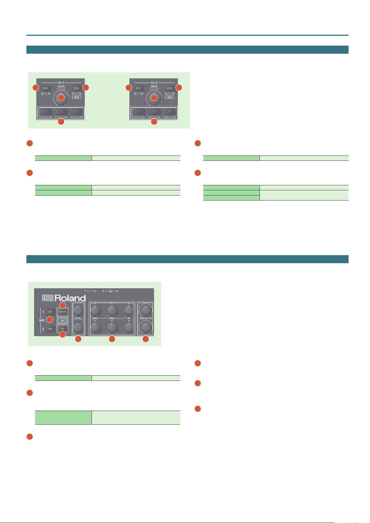
Here you can adjust the eects using two independent eect sections (FX 1, FX 2).
Panel Descriptions
1
3
4
1
[CH1] button
Turns FX 1 (FX 2) on/o for CH 1.
[SHIFT] + [CH1] Turns FX 1 (FX 2) on/o for CH 3.
2
[CH2] button
Turns FX 1 (FX 2) on/o for CH 2.
[SHIFT] + [CH2] Turns FX 1 (FX 2) on/o for CH 4.
Long press [CH2] Turns FX 1 (FX 2) on/o for sampler.
2
Mic Section
Here you can apply a vocal eect to the mic input.
1
3
4
2
3
[LEVEL] knob
Adjusts the depth of the eect.
[SHIFT] + [LEVEL] knob Adjusts the time for which the eect is applied.
4
Eect button [1]–[3]
Turn the eect on/o.
[SHIFT] + Eect button Changes the eect type.
[2] + [LEVEL] knob
[3] + [LEVEL] knob
In single FX mode (p. 15), change the values of the
eect parameters.
2
1
3
4
1
MIC 1, 2 [ON] buttons
Turns the mic input on/o.
[ON] + [SELECT (ENTER)] knob Adjusts the mic gain.
2
[DUCK] button
Turns on/o ducking (an eect that lowers the output volume of
sounds other than the mic when mic input is present) for mic 1 and 2.
[DUCK] + [SELECT (ENTER)] knob
3
[FX] button
Turns on/o the vocal eect for mic 1 and 2.
* You can change the vocal eect in Scene Edit (p. 18).
5
Lets you adjust the output level when ducking is on.
This adjusts the MASTER/BOOTH/ZONE levels
simultaneously.
6
4
[LEVEL] knob
Adjusts the output volume of the mic.
5
[HI], [MID], [LOW] knobs
Boost/cut the volume of the high-frequency, mid-frequency, and lowfrequency regions.
6
[VOCAL FX] knob
Adjusts the depth of the vocal eect.
7
Page 8

Panel Descriptions
Front Panel
Microphone
Audio player
Headphones
1
PHONES jacks
1 2 3 4
Connect headphones here.
Stereo 1/4” and stereo miniature plugs are supported.
2
PHONES [LEVEL] knob
Adjusts the volume of the headphones.
3
PHONES [MIXING] knob
Adjusts the monitor volume balance of the channel whose Channel
[CUE] button is lit and the master output.
4
[SPLIT/STEREO] switch
Selects whether the sound of channels whose channel [CUE] button
is lit are mixed in stereo with the master output, or are played back
individually from left and right in mono.
SPLIT
STEREO
The sound of the channel whose Channel [CUE] button is lit is heard from
the L-side, and the master output monitor is heard from the R-side.
The sound of the channel whose channel [CUE] button is lit is mixed with
the master output, and output in stereo.
5
6
7 8
5
CROSS FADER [CH 1]–[CH 4] switch
9
Keyboard
Specify the output destination of the channels.
A Output to cross fader A.
THRU Output directly without passing through the cross fader.
B Output to cross fader B.
6
CROSS FADER [CURVE] knob
Adjusts the response curve of the cross fader.
7
AUX IN select switch
Set this according to the input source that’s connected to the AUX IN
jacks.
MIC If a mic is connected
MONO If you want to input sound in mono
STEREO If you want to input sound in stereo
8
AUX IN [LEVEL] knob
Adjusts the level of the sound that’s input to the AUX IN jacks.
9
AUX IN jacks (L, R, STEREO)
Connect these to a mic or audio device.
Rear Panel (Connecting Your Equipment)
Turntable
(analog)
1
Microphone
DJ player
Turntable
(analog)
2
3
4
5 6
7 8 9
MIDI device
10
Computer
Computer
Audio player
Powered speakerPowered speaker, amp
Speaker, recorder
8
Page 9

Rear Panel (Connecting Your Equipment)
To prevent malfunction and equipment failure, always turn down the volume, and turn o all the units before making any connections.
Panel Descriptions
1
MIC IN 1, 2 connector
Connect your microphone here.
* Pin assignment of MIC IN connectors
2
INPUT (CH 1–CH 4) jacks
These jacks input sound to channels 1–4. The CH 1 and C H2 INPUT
jacks support phono input from MM-type cartridges.
Set the input select switch of the mixer section appropriately for the
device you’re connecting.
3
PHONO GROUND terminal
If a turntable (analog) is connected to the CH 1 or CH 2 INPUT jacks,
connect the turntable’s ground terminal here. This suppresses noise
from the turntable.
* Unsuitable places for connection
5 Water pipes (may result in shock or electrocution)
5 Gas pipes (may result in re or explosion)
5 Telephone-line ground or lightning rod (may be dangerous in the
event of lightning)
4
MASTER OUT (L, R) connectors
Connect your powered speakers or power amp here.
Both XLR type and RCA phono type plugs are supported.
* Pin assignment of MASTER OUT connector (XLR type)
8
PC A, B port
Use the included USB cable to connect this port to your computer.
To connect this to your computer, you must install the USB driver.
&“Installing the Software” (p. 3)
9
[POWER] switch
This turns the power on/o.
NOTE
When turning o the power, follow the directions that appear in the
display.
* The power to this unit will be turned o automatically after a
predetermined amount of time has passed since it was last used for
playing music, or its buttons or controls were operated (Auto O
function).
If you do not want the power to be turned o automatically,
disengage the Auto O function.
For details on how to disable this function, refer to p. 20.
NOTE
5 Any settings that you are in the process of editing will be lost when
the power is turned o. If you have any settings that you want to keep,
you should save them beforehand.
5 To restore power, turn the power on again.
10
DC IN jack
Connect the included AC adaptor here.
* Use the cord hook to secure the cord of the AC adaptor as shown in
the illustration.
5
BOOTH OUT (L, R) jacks
These are the output jacks for booth monitoring.
* Pin assignment of BOOTH OUT jacks
6
ZONE OUT (L, R) jacks
Use these output jacks when you want to send signals to another
location independently from MASTER OUT or BOOTH OUT.
Connect them to your speakers or recorder.
7
MIDI OUT connector
This outputs MIDI messages such as MIDI clock.
Power cord
Indicator
AC Outlet
9
Page 10

Using Serato DJ Pro
This document explains basic use of Serato DJ Pro. For details on the functions and use of the software, refer to the Serato DJ Pro user manual (PDF).
Here we explain operation for when a computer is connected to the PC A port.
Starting Serato DJ Pro
* Before turning the unit on/o, always be sure to turn the volume down. Even with the volume turned down, you might hear some sound when
switching the unit on/o. However, this is normal and does not indicate a malfunction.
1. Connect your computer to the rear panel PC A port.
2. Press the [POWER] switch to power-on the DJ-707M.
3. Turn on the power of the equipment that’s connected to the
DJ-707M.
4. Start Serato DJ Pro.
Mac OS
In the Finder, open the [Applications] folder and click the
[Serato DJ Pro] icon.
Basic Operations in Serato DJ Pro
Songs shown in the browser view can be imported into a deck area, and controlled from the DJ-707M.
1
2
1
Windows 7
In the [Start] menu, click [All Programs] & [Serato]
[Serato DJ Pro] & [Serato DJ Pro] icon.
Windows 8.1
In the [App View], click the [Serato DJ Pro] icon.
Windows 10
In the [Start] screen or [App View], click the [Serato DJ Pro] icon.
1
Deck section
2
Waveform panel
3
crate panel
4
Library
&
3
Importing a Song
Here we’ll explain typical operations for importing a song.
* Serato DJ Pro provides a variety of ways to import songs. For details,
refer to the Serato DJ Pro user manual.
* If you’re using Serato Corporation’s DJ software (Scratch Live, ITCH,
Serato DJ Pro Intro) and you have already created a song library, the
library you created can be used as-is.
* If you’re using Serato DJ Pro Intro and you’ve already created a song
library, there might be cases in which songs need to be re-analyzed.
4
1. In Serato DJ Pro, click the [Files] key.
The [Files] panel opens, and the les on your computer and on the
peripheral devices connected to your computer are displayed.
2. In the [Files] panel, click the folder that contains the songs
you want to add to the library.
3. Drag and drop the selected folder onto the create panel.
A crate is created, and the songs are added to the library.
Loading a Song
Here’s how to load a song so that it can be output.
1. On the DJ-707M, press the [BACK] button to move the cursor
to the crate panel.
2. Press the DECK [1/3] or DECK [2/4] button to select the deck
into which you want to load a song.
3. By turning the [SELECT] knob of the deck into which you want
to load a song, move to the folder that contains the song you
want to load, and then press the [SELECT] knob.
The cursor moves to the library.
4. Turn the [SELECT] knob to select the song that you want to
load, and press the [SELECT] knob.
The DJ-707M’s display shows the playback tempo (BPM) of the loaded
song.
Deck 1 Deck 2
Ì:125.0 Ì:119.2
Ì:196.3 Ì:117.9
Deck 3 Deck 4
10
Page 11

Using Serato DJ Pro
Playing a Song
1. Set the DJ-707M’s knobs and switches as follows.
Input select switches “PC” position
[MASTER] knob
[TRIM] knob
[BOOTH] knob
[ZONE] knob
[HI], [MID], [LOW] knobs
[FILTER/FX] knob
Channel faders Lowest position
Cross fader Center
CROSS FADER [CH 1]–[CH 4] knobs “THRU” position
2. Press the [
r
] button to play back the loaded song.
Turned all the way to the left
Center
3. Move the channel fader upward and turn the [TRIM] knob
toward the right to adjust the volume.
Adjust the volume so that the channel level in the level indicator is lit in
the orange-colored area.
4. Turn the [MASTER] knob toward the right to adjust the level of
the speakers.
Closing Serato DJ Pro
1. Close the Serato DJ Pro screen.
Mac OS
In the upper left of the Serato DJ Pro screen, click the [6] (red: close)
button.
Monitoring Through Headphones
1. Set the DJ-707M’s knobs as follows.
PHONES [MIXING] knob
PHONES [LEVEL] knob
Turned all the way to the left
2. Press the channel [CUE] button of the channel that you want to
monitor.
3. Turn the [VOLUME] knob toward the right to adjust the
headphone level.
Windows
In the upper right of the Serato DJ Pro screen, click the [X] button.
A conrmation screen appears.
2. Click [Yes] to close Serato DJ Pro.
3. Turn o the power of the equipment that’s connected to the
DJ-707M.
4. Press the [POWER] switch.
The display indicates “Are you sure to Power o.”
Are you sure to
Power off [YES]
5. Press the [SELECT (ENTER)] knob to power-o the DJ-707M.
11
Page 12

Operating the DJ-707M
Performance Pad Operations
Hot Cue Operations (HOT CUE)
By specifying a hot cue, you can instantly play back from the specied
location.
You can specify up to eight hot cues for each song.
1. Press a [HOT CUE] button to make the button light in white.
Hot cue mode is selected.
2. During playback or while paused, press a performance pad
that is unlit.
A hot cue is assigned to the pad that you pressed.
Hot cues (1–8) are assigned to the performance pads as follows.
Hot cue 1 Hot cue 2 Hot cue 3 Hot cue 4
Hot cue 5 Hot cue 6 Hot cue 7 Hot cue 8
3. Press a performance pad that is lit (i.e., a pad to which a hot cue
is assigned).
Playback starts from the specied location.
MEMO
If you hold down the [SHIFT] button and press a performance pad, the
hot cue location of the pad you pressed is cleared.
Cue Loop Operations (CUE LOOP)
When you press a performance pad, the auto loop point moves to the cue
point of the pad that you pressed, and auto loop playback occurs.
1. Hold down the [SHIFT] button and press the [HOT CUE] button
to make the button light in blue.
Cue loop mode is selected.
2. During playback, press a performance pad that’s lit.
Auto loop playback starts with the hot cue that’s assigned to the pad you
pressed.
The loop length is the same as the auto loop beat setting.
MEMO
If you press a pad that’s unlit, hot cue is specied, and auto loop playback
starts immediately.
Loop in points are assigned to the performance pads as follows.
Auto Loop Operations (AUTO)
By pressing performance pads, you can play back loops in synchronization
with the length (beat) assigned to each pad.
Based on the BPM of the song, a loop of 1/64–2 beats is specied
automatically.
1. Press a LOOP [AUTO] to make the button light in blue.
Auto loop mode is selected.
2. During playback, press a performance pad.
The loop continues playing at the beat assigned to the pad you pressed.
1/64 beat 1/32 beat 1/16 beat 1/8 beat
1/4 beat 1/2 beat 1 beat 2 beats
3. Adjust the loop playback parameters.
5 During loop playback, press the PARAMETER [−] button
The loop playback length is halved.
5 During loop playback, press the PARAMETER [+] button
The loop playback length is doubled.
4. Press the same performance pad once again.
Loop playback is cancelled.
Roll Operations (ROLL)
When you press a performance pad, a roll continues playing in time with
the length (beat) that’s assigned to each pad, as long as you continue
holding down the pad.
The song continues progressing in the background even while the roll is
playing.
When you cancel roll playback, song playback resumes from the location to
which the song had progressed while the roll was being played.
NOTE
Roll can only be used during the song playback.
1. Hold down the [SHIFT] button and press the LOOP [AUTO]
button to make the button light in light blue.
Roll mode is selected.
2. Hold down a performance pad.
A roll plays at the beat that’s assigned to the pad you pressed.
Loop 1 Loop 2 Loop 3 Loop 4
Loop 5 Loop 6 Loop 7 Loop 8
3. Adjust the loop playback parameters.
5 During loop playback, press the PARAMETER [−] button
The loop playback length is halved.
5 During loop playback, press the PARAMETER [+] button
The loop playback length is doubled.
5 Hold down the [SHIFT] button and press the same performance pad
Return to the loop in point and continue loop playback.
4. Press the same performance pad once again.
Loop playback is cancelled.
12
1/64 beat 1/32 beat 1/16 beat 1/8 beat
1/4 beat 1/2 beat 1 beat 2 beats
3. Adjust the loop playback parameters.
5 During loop playback, press the PARAMETER [−] button
The loop playback length is halved.
5 During loop playback, press the PARAMETER [+] button
The loop playback length is doubled.
4. Take your nger o the performance pad.
Song playback resumes from the location to which the song had
progressed while the roll was being played.
Page 13

Operating the DJ-707M
Manual Loop Operations (MANUAL)
You can control loop playback by specifying the loop-in and loop-out
points.
The specied loop is saved in a loop slot.
1. Press a LOOP [MANUAL] button to make the button light in
yellow green.
Manual loop mode is selected.
2. During playback, press the Loop IN pad to specify the loop IN
point.
Slot 1 Slot 2 Slot 3 Slot 4
Loop INLoop
OUT
Loop
EXIT
Loop
ON/OFF
3. During playback, press the Loop OUT pad to specify the loop
IN point.
Loop playback begins between the loop IN point and the loop OUT point.
The loop is saved in the loop slot, and the performance pad corresponding
to the saved slot blinks.
5 When you press the pad of slot 1–4 during loop playback, the loop saved
in the slot whose pad you press is played.
4. Adjust the loop playback parameters.
5 During loop playback, press the PARAMETER [−] button
The loop playback length is halved.
5 During loop playback, press the PARAMETER [+] button
The loop playback length is doubled.
5. To exit manual loop, press the Loop EXIT pad during loop
playback.
6. To play the manual loop once again, press the Loop ON/OFF
pad.
If you press the loop ON/OFF pad during playback after exiting manual
loop, manual loop is re-specied.
Adjusting the length of manual loop
5 During playback, you can press the Loop IN pad and then use the jog dial
to make ne adjustments to the loop IN point. If you once again press the
Loop IN pad, you’ll return to loop playback.
5 During playback, you can press the Loop OUT pad and then use the jog
dial to make ne adjustments to the loop OUT point. If you once again
press the Loop OUT pad, you’ll return to loop playback.
Saved Loop Operations (SAVED LOOP)
You can save loops in Serato DJ Pro’s loop slots, and recall a saved loop.
1. Hold down the [SHIFT] button and press the LOOP [MANUAL]
button to make the button light in yellow green.
Saved loop mode is selected.
2. During loop playback, press a performance pad.
The loop is assigned to Serato DJ Pro’s loop slot.
Slot 1 Slot 2 Slot 3 Slot 4
Slot 5 Slot 6 Slot 7 Slot 8
3. Hold down the [SHIFT] button and press a performance pad.
Playback returns to the beginning of the loop and continues.
4. Press the same performance pad once again.
Loop playback is cancelled.
Slicer Operations (SLICER)
Slicer divides the specied region into eight, and assigns the divided
regions to the performance pads. While you hold down a performance pad,
the sound of the region assigned to that pad plays as a loop.
The song continues progressing in the background even while looping.
When you cancel loop playback, song playback resumes from the location
to which the song had progressed during loop playback.
NOTE
5 Slicer can only be used during the song playback.
5 You can’t use the slicer on a song for which the beat grid is not specied.
For details on the beat grid, refer to the Serato DJ Pro user manual.
1. Press a LOOP [MANUAL] button to make the button light in red.
Slicer mode is selected.
MEMO
If you hold down the [SHIFT] button and press the [SLICER] button to make
the button light in blue, slicer loop mode is selected.
2. Hold down the [SHIFT] button and use the PARAMETER [−] [+]
buttons to select the length (beats) of the specied region.
The setting changes each time you press the button.
The length of the specied region can be set to 2 beats, 4 beats, 8 beats,
16 beats, 32 beats, or 64 beats.
The eight divided regions are assigned to the performance pads as follows.
1 8765432
Region 1 Region 2 Region 3 Region 4
Region 5 Region 6 Region 7 Region 8
3. Use the PARAMETER [−] [+] buttons to specify the slicer’s
quantize setting.
The quantize setting changes the length of loop playback that occurs
when you hold down a pad.
You can choose from four types of quantize setting.
Example
If quantize is set to 1:
The entire region assigned to the pad you press is played as a loop.
If quantize is set to 1/2:
The rst 1/2 of the region assigned to the pad you press is played as a
loop.
13
Page 14

Operating the DJ-707M
4. Hold down a performance pad.
While you hold down the pad, the length that you specied by the
quantize setting is continuously played as a loop.
5. Release the performance pad.
Song playback resumes from the location to which the song had
progressed during loop playback.
Using slicer mode and slicer loop mode
Slicer mode
When the playback location progresses to the end of the region that was
divided into eight, the region on the screen shifts to show the next eight
divisions, and that region divided into eight is assigned to the pads.
1 8765432 1 8765432
Slicer loop mode
When the playback location progresses to the end of the region that was
divided into eight, the playback location returns to the beginning of the
currently-specied region.
1 8765432 1 8765432
Serato Sampler Operations (SAMPLER)
You can use the performance pads to play songs (samples) that are loaded
into Serato Sampler’s sample slots.
1. In Serato DJ Pro, click the [Sampler] key to access the Samples
panel.
2. Press the [SAMPLER] button to make it light in magenta.
Sampler mode is selected.
3. Use the PARAMETER [−] [+] buttons to switch the Serato
Sampler’s banks.
The Serato Sampler has four banks (A–D), and each bank has eight slots.
4. Drag and drop songs into the Sampler panel to load a sample
into each slot of the Sampler panel.
The sampler settings and the loaded samples are saved.
* You can also load a sample by using the [SELECT (ENTER)] knob to
select a sample and then pressing a performance pad while holding
down the [SHIFT] button.
5. Press a performance pad.
The sample of the slot that’s assigned to the pad you pressed is played.
Pitch Play Operations (PITCH PLAY)
The pitch of the loaded song can be changed in semitone steps.
NOTE
In order to use Pitch Play mode, you must separately purchase the Pitch’n
time DJ and activate Pitch’n time DJ.
1. Hold down the [SHIFT] button and press the [SAMPLER] button
to make the button light in turquoise.
Pitch play mode is selected.
2. Press a performance pad to change the pitch.
No change
Pitch is lowered in semitone steps
5 By using the PARAMETER [−] [+] buttons you can change the range of
pitch change.
Velocity Sampler Operations
The functionality is the same as in sampler mode, but when you press a
pad, the sample’s playback volume changes depending on how strongly
you press the pad.
Pitch is raised in semitone steps
Semitone
down
1. Press the [SAMPLER] button twice to make the button light in
purple.
Velocity sampler mode is selected.
2. Press a performance pad.
The sample of the slot assigned to the pad you press is played.
The more strongly you press the pad, the louder the sample’s playback
volume.
Saved Flip Operations
By pressing a performance pad you can play back a saved Flip.
NOTE
In order to use Saved Flip mode, you must separately purchase the Serato
Flip Expansion Pack and activate Serato Flip.
1. Press the [HOT CUE] button twice to make the button light in
orange.
Saved Flip mode is selected.
2. Press a lit performance pad.
The Flip that is in the Flip slot corresponding to the pad you pressed starts
playing.
Slot 1 Slot 2 Slot 3 Slot 4
Slot 5 Slot 6 Slot 7 Slot 8
Slot 1 Slot 2 Slot 3 Slot 4
Slot 5 Slot 6 Slot 7 Slot 8
* The type of playback changes depending Serato Sampler’s playback
mode. For details, refer to the Serato DJ Pro user manual.
MEMO
If you hold down the [SHIFT] button and press the performance pad,
sample playback stops.
14
5 If you hold down the [SHIFT] button and press a lit performance pad, the
Flip that is in the corresponding Flip slot is recalled, but you won’t move
to the beginning of the Flip. In this case, the Flip plays when the song
playback position reaches the beginning of the ip.
Song Analysis
Song analysis begins when you press the DJ-707M’s [SELECT] knob to load
a song into a deck, but if you’re using Serato DJ Pro as an oine player (i.e.,
without the DJ-707M being connected), you can analyze songs ahead of
time.
If analysis is nished for a song, the BPM and waveform are displayed
immediately after you load that song into a deck.
For details on how to analyze songs with the oine player, refer to the
Serato DJ Pro user manual.
* Depending on the number of songs, analysis might take some time.
Page 15

Operating the DJ-707M
Eect Operations
Serato DJ Pro has two eect units (FX1, FX2) which you can use with the
selected deck.
DJ-FX panel
When you click “FX” in the upper left of Serato DJ Pro’s main screen, the
DJ-FX panel opens.
Multi FX mode
You can select up to three eects for each eect unit.
1 1 1
4 5
4 5 4 5
2 3
Single FX mode
You can select one eect for each eect unit, and control multiple
parameters of the selected eect.
1
4
5 6 6 6 6
Currently selected eect type
1
Time at which the eect is applied
2
Number of the deck that uses the eect unit is highlighted
3
Eect on/o status (highlighted when on)
4
Eect depth
5
Eect parameters and settings
6
2 3
5. Use the [LEVEL] knob to adjust the eect depth.
6. Hold down the [SHIFT] button and turn the [LEVEL] knob to
adjust the time at which the eect is applied.
Single FX Mode Operations
1. In the DJ-FX panel, click to select the single FX mode.
2. Press the button of the deck (channel) that will use the eect
unit, making the button light.
In the case of deck 3 or 4, hold down the [SHIFT] button and press the
[CH 1] ([CH 2]) button.
In the DJ-FX panel of the Serato DJ Pro screen, the number of the deck
that uses the eect unit is highlighted.
MEMO
By long pressing the [CH 2] button you can apply an eect to the sampler
sound.
In Serato DJ Pro’s Sampler panel, set OUTPUT to “A.”
3. Hold down the [SHIFT] button and press the eect [1] button
to select the eect type.
The eect type changes each time you press the button.
Multi FX Mode Operations
1. In the DJ-FX panel, click to select the multi FX mode.
2. Press the button of the deck (channel) that will use the eect
unit, making the button light.
In the case of deck 3 or 4, hold down the [SHIFT] button and press the
[CH 1] ([CH 2]) button.
In the DJ-FX panel of the Serato DJ Pro screen, the number of the deck
that uses the eect unit is highlighted.
MEMO
By long pressing the [CH 2] button you can apply an eect to the sampler
sound.
In Serato DJ Pro’s Sampler panel, set OUTPUT to “A.”
3. Hold down the [SHIFT] button and press an eect button to
select the eect type.
The eect type changes each time you press the button.
4. Press the eect [1] button to turn the eect on (button lit).
5. Press the eect [2] or [3] button to switch the value of the
eect parameters.
6. Hold down the eect [2] or [3] button and turn the [LEVEL]
knob to adjust the value of the eect parameters.
7. Use the [LEVEL] knob to adjust the eect depth.
4. Press the eect button to turn the eect on (button lit).
8. Hold down the [SHIFT] button and turn the [LEVEL] knob to
adjust the time at which the eect is applied.
15
Page 16

Operating the DJ-707M
Recording
You can use Serato DJ Pro’s recording functionality to record sounds that
you’ve mixed on the DJ-707M.
* For details, refer to the Serato DJ Pro user manual.
1. In Serato DJ Pro, click the [REC] key to access the REC panel.
2. Click [REC] to start recording.
3. To stop recording, click [REC] once again.
4. To save, enter a le name in the text entry eld and click [Save].
Inputting Sound from an External Device
Audio from devices such as a DJ player or turntable (analog) can be input
directly to the rear panel INPUT (CH 1–CH 2) jacks, and mixed by the
DJ-707M’s mixer section.
You can also use Serato DJ Pro’s eect units to apply eects to the external
audio inputs.
You can use the mic section to apply a vocal eect to the audio input from
mics connected to the MIC IN 1 or 2 jacks.
Inputting Sound from a DJ Player
1. Connect your DJ player or other line-level device to any of the
INPUT (CH 1–CH 4) jacks.
2. As appropriate for the channel to which your line-level device
is connected, set the corresponding input select switch to
“LINE.”
3. Use the [TRIM] knob and channel fader to adjust the output
level.
5 You can use the [HI], [MID], and [LOW ] knobs to adjust the volume of the
high, mid, and low-frequency regions.
5 You can use the [FILTER/FX] knob to apply a lter.
5 You can operate the eect section to apply Serato DJ Pro’s eects.
Inputting Sound from a Turntable
1. Connect your turntable to either of the INPUT jacks (CH 1 or CH
2).
2. As appropriate for the channel to which your turntable is
connected, set the corresponding input select switch to
“PHONO.”
3. Use the [TRIM] knob and channel fader to adjust the output
level.
5 You can use the [HI], [MID], and [LOW ] knobs to adjust the volume of the
high, mid, and low-frequency regions.
5 You can use the [FILTER/FX] knob to apply a lter.
5 You can operate the eect section to apply Serato DJ Pro’s eects.
Inputting Sound from a Mic
1. Connect a mic to the MIC IN 1 or 2 jack.
2. In the mic section, press the MIC 1 or 2 [ON] button to make it
light.
3. Use the mic section’s [LEVEL] knob to adjust the output volume
of the mic.
5 You can use the [HI], [MID], and [LOW ] knobs to adjust the volume of the
high, mid, and low-frequency regions.
5 Use the [DUCK] button to turn ducking on (lit) or o (unlit).
5 Use the [FX] button to turn the vocal eect on (lit) or o (unlit). Use the
[VOCAL FX] knobs to adjust the depth of the vocal eect.
TR Operations
For deck 3, you can play “patterns” created using drum sounds
(instruments) such as those of a Roland TR-808 rhythm machine.
What are patterns?
“Patterns” contain performance data for instruments. Sixteen patterns are
provided.
Each pattern has eight “variations,” and when you select a pattern, the
variations are automatically assigned to performance pads 1–8.
Pattern 16
Variation1Variation2Variation3Variation
Pattern 2
Pattern 1
Variation1Variation2Variation3Variation
Variation5Variation6Variation7Variation
Variation5Variation6Variation7Variation
4
4
8
8
Playing Patterns
Preparation
1. Set the mixer section CH3 input select switch to
“TR.”
2. In the left deck, press the DECK [1/3] button to
make it light red.
Selecting a pattern
1. Turn the [SELECT (ENTER)] knob to select a pattern (01–16), and
press the knob to conrm.
TR: Pattern
[01]
The variations of the selected pattern are assigned to performance pads
1–8.
Playing back a pattern
1. Press a performance pad 1–8 to select a variation.
The pad you pressed blinks.
5 You can select multiple variations by holding down a pad and pressing
another pad.
2. Press the [
The variation starts playing.
5 If you selected multiple variations, the variation whose pad is blinking
plays, and then the other variations play consecutively starting with the
lowest-numbered variation.
5 If you select the next variation during playback, the pad you press blinks.
5 If you hold down the [SHIFT] button and press a pad, the variation of
the pad that you press is reserved. When the currently-playing variation
nishes playing, playback automatically switches to the reserved
variation.
r
] button.
16
Page 17

Operating the DJ-707M
Panel Operations When Using TR
While stopped:
Press [r]
Press [SHIFT] + [r]
Press [CUE]
Press [SHIFT] + [CUE]
Tempo slider Adjusts the playback tempo.
Press [RANGE]
Jog dial Nudges to adjust the playback timing.
Press [SYNC]
Press [SHIFT] + [SYNC] Cancels synchronization.
Plays from the previously-stopped variation.
While playing:
Stops.
While stopped/playing:
Plays the variation from the cue point.
While stopped:
Species the cue point.
If already at the cue location, the variation plays while you
continue holding down the button.
While playing:
Stops at the cue point.
While stopped:
Species the cue point.
While playing:
Plays consecutively from the lowest-numbered of the
selected variations.
Species the range of change when operating the tempo
slider.
Each time you press the button, the range of change is
switched as follows.
8%016%050%08%0
Synchronizes to a song other than deck 3.
If you press the button once again while synchronized, resynchronization occurs.
Pad mode
OSC Operations
For deck 4, you can use the performance pads to play back sound eects.
Preparation
1. Set the mixer section CH4 input select switch to
“OSC.”
2. In the right deck, press the DECK [2/4] button to
make it light red.
Playing back a sound eect
1. Press a performance pad 1–8.
A sound eect plays while you hold down the pad.
Sound
eect 1
Sound
eect 5
Sound
eect 2
Sound
eect 6
Sound
eect 3
Sound
eect 7
Sound
eect 4
Sound
eect 8
Playing back a sound eect with velocity
1. Press the [SAMPLER] button to make it light in purple.
2. Press a performance pad 1–8.
A sound eect with velocity plays while you hold down the pad.
Hot cue
Press [HOT CUE]
Press [SHIFT] + performance
pad 1–8
Plays the variation at the moment you press the pad.
* By holding down a pad and successively pressing other
pads, you can play multiple variations consecutively.
The variation of the pad that you press is reserved.
When the currently-playing variation nishes playing,
playback automatically switches to the reserved variation.
Auto loop
Press [AUTO] Starts looping at the moment you press the pad.
Press performance pad 1–8
Press PARAMETER [–] [+] Halves or doubles the loop.
Looping occurs at the beat (1/64, 1/32, 1/16, 1/8, 1/4, 1/2, 1, 2)
that’s assigned to each pad.
Loop roll
Press [SHIFT] + [AUTO]
Press performance pad 1–7
Press PARAMETER [–] [+] Halves or doubles the loop.
Plays the loop only while you hold down the pad.
When you take your nger o the pad, you return to the
original position.
Looping occurs at the beat (1/64, 1/32, 1/16, 1/8, 1/4, 1/2, 1)
that’s assigned to each pad.
Manual loop
Press [MANUAL] Loop-plays between the specied loop-in and loop-out.
Press performance pad 1–4 Selects a loop slot.
Press performance pad 5 Species the loop-in point.
Press performance pad 6 Species the loop-out point.
Press performance pad 7, 8 Turns loop on/o.
Slicer
Press [SLICER]
Press PARAMETER [–] [+] Halves or doubles the loop.
Press [SHIFT] + PARAMETER [–] [+]
Loop-plays the beat at the moment you pressed the pad.
When you take your nger o the pad, you return to the
original position.
Halves or doubles the beat that’s looping.
Sampler
Press [SAMPLER] Plays the instrument that’s assigned to the pad.
Press [SHIFT] + [SAMPLER] Plays the instrument that’s assigned to the pad, with velocity.
Press [SHIFT] + performance
pad 1–8
Mutes or un-mutes each instrument.
If muted, the pad is unlit.
17
Page 18

Menu Operations
Recalling, Editing, and Saving a Scene
A “scene” contains settings for mixer, mic, and output. You can save ten
scenes in the DJ-707M unit.
Scene
5 Mixer settings
5 Mic 1–3 settings
5 MASTER OUT settings
5 BOOTH OUT settings
5 ZONE OUT settings
Mic section
Turn each
button on/o
Save
Load
Scene 1
Scene 1
Scene 1
Scene 1
Scene 10
When the unit is shipped from the factory, several scenes are already saved.
You can edit and overwrite these scenes.
Scene Explanation
1: Standard
2: Two-Room
3: DECK4-ZONE
4: MICs-ZONE
5: SoundBoost
The same audio as MASTER OUT is output from ZONE OUT.
This allows the same use as a standard DJ controller.
Mic audio is not output from ZONE OUT.
This is useful when you want to output only the song audio to a
dierent venue than the main venue.
The deck 4 audio is output only from ZONE OUT, without being mixed
into MASTER OUT or BOOTH OUT.
This is useful when you want to output dierent music to the main
venue and to another venue.
The mic audio is output only from ZONE OUT.
This is useful when you want the mic audio to be output from dierent
speakers.
A multi-band compressor is applied to each output.
This makes mixing easier when using TR, etc.
Recalling a Scene (Scene Load)
1. Press the [MENU] button.
2. Turn the [SELECT (ENTER)] knob to select “Scene Load,” and
press the knob.
Scene Load
1:Standard <
3. Turn the [SELECT (ENTER)] knob to select the scene that you
want to recall, and press the knob.
A conrmation message appears.
Load Scene?
CANCEL[OK]
If you decide to cancel, use the [SELECT (ENTER)] knob to make “CANCEL”
blink, and press the knob.
4. Press the [SELECT (ENTER)] knob.
The selected scene is loaded.
Editing a Scene (Scene Edit)
1. Press the [MENU] button.
2. Turn the [SELECT (ENTER)] knob to select “Scene Edit,” and
press the knob.
MENU>SCENE EDIT
Mixer Setting
3. Turn the [SELECT (ENTER)] knob to select the setting that you
want to edit, and press the knob.
Mixer: FX(All)<
FILTER
4. Turn the [SELECT (ENTER)] knob to select the parameter that
you want to edit, and press the knob.
The parameter value blinks.
5. Turn the [SELECT (ENTER)] knob to change the value, and press
the knob.
The value is conrmed.
Parameter Value (Bold: default) / Explanation
Mixer Setting
FX (ALL)
FX (Ch1–4)
Anti.FB
Mode SERATO, INTERNAL
DVS Deck
FX (ALL) species the same eect for the entire channel mixer.
FX (Ch1–4) individually specify an eect for each channel.
FILTER
DUB ECHO
JET
NOISE
REVERB Applies a reverb.
DELAY Applies a delay.
BIT CRUSH
PHASER
NOISE2
SIDE CHAIN Lowers the level in synchronization with the tempo.
SLICER Slices the sound in synchronization with the tempo.
ROLL Plays the sound repeatedly.
ROLL FILTER Plays the sound repeatedly and applies a lter.
LOOP PITCH Plays the sound repeatedly and modies the pitch.
LOOP FILTER
VINYL SIM Simulates sound heard from an analog record.
Selects the output that uses anti-feedback for the mic input.
OFF
MASTER
BOOTH
ZONE
Species the controller when using DVS.
TURNTABLE Turntable (analog)
CDJ DJ player
Applies a lter.
If you turn the [FILTER/FX] knob toward the right, only
the high-frequency range is heard. If you turn the
knob toward the left, only the low-frequency range
is heard.
Adds a delayed sound several times while attenuating
it.
If you turn the [FILTER/FX] knob toward the right,
the echo eect is added only to the high-frequency
range.
If you turn the knob toward the left, the echo eect is
added only to the mid-frequency range.
The farther you turn the knob, the longer the interval
between echoes.
Applies a anger eect.
If you turn the [FILTER/FX] knob toward the right, the
peak varies cyclically.
If you turn the knob toward the left, the peak lowers
according to the knob’s position.
Adds noise.
If you turn the [FILTER/FX] knob toward the right, the
pitch of the noise rises.
If you turn the knob toward the left, the pitch falls.
Creates a lo- sound.
If you turn the [FILTER/FX] knob toward the right, only
the high-frequency range is heard. If you turn the
knob toward the left, only the low-frequency range
is heard.
Applies a phaser eect.
If you turn the [FILTER/FX] knob toward the right, the
peak varies cyclically. If you turn the knob toward the
left, the peak lowers according to the knob’s position.
Adds peaky noise.
If you turn the [FX] knob toward the right, the pitch
of the noise rises. If you turn the knob toward the left,
the pitch falls.
Plays the sound repeatedly and modies the pitch
and lter.
Anti-feedback is not used.
Anti-feedback is applied only to the output sound
from the selected jacks.
Selects whether mixing is done in Serato DJ Pro or in
the DJ-707M.
18
Page 19

Menu Operations
Parameter Value (Bold: default) / Explanation
Mic1–3 Setting
Gain -60–-10–0 dB Species the mic gain.
EQ
EQ Hi
EQ Mid (*1)
EQ Low
FX
FX Depth (*1) 0–255 Adjusts the depth of the vocal eect.
Low Cut 0–2–10
Noise Gate 0–2–10
Pan L50–C00–R50 Specica il pan (posizione stereo) in uscita.
Duck Level -6, -12, -18, -24, INF
Duck (Mstr)
Duck (Both)
Duck (Zone)
Species the type of equalizer.
EQUALIZER An equalizer with general-purpose settings.
ISOLATOR
-127–0–127
Species the vocal eect.
REVERB Reverb is applied.
ECHO Echo is applied.
REVERB ECHO Reverb and echo are applied simultaneously.
DUB ECHO
PITCH UP
PITCH DOWN
FORMANT UP
FORMANT DOWN
AUTO PITCH
ROBOT
DOUBLE Layers the same voice to add depth.
HARMONY ABOVE Adds harmony to the voice a fth above.
HARMONY BELOW Adds harmony to the voice a fourth below.
MEGAPHONE
RADIO
TEMPO DELAY
ON, OFF
An equalizer with an extremely strong amount of
volume cut.
Adjust the volume of the high, mid, and lowfrequency regions.
Adds a delayed sound several times while attenuating
it.
Raise or lower the pitch of the voice.
Raise or lower the formant of the voice.
Selecting DOWN gives the voice a masculine
character, and selecting UP gives the voice a feminine
character.
Pitch-corrects the voice.
If you hold down the [SHIFT] button and press the
channel [CUE] button, the pitch-correction follows
the key information of the song that’s loaded into
the deck.
Transforms your voice into that of a robot, with a
xed pitch and an expressionless character.
Gives your voice a distorted character as if you were
speaking through a megaphone.
Simulates sound heard from a radio.
Delay is applied.
If you hold down the [SHIFT] button and press the
channel [CUE] button, the tempo-correction follows
the tempo of the song that’s loaded into the deck.
Adjusts the strength of the low cut lter applied to
the mic audio.
Higher values produce a stronger eect.
Species the strength of the noise gate applied to
the mic audio.
As the value increases, even higher-level sound will
be cut.
Adjusts the output level of other than the mic when
the [DUCK] button is turned on.
Species whether the MASTER OUT, BOOTH OUT, and
ZONE OUT output audio is aected by ducking (ON)
or is not aected (OFF).
MsterOut Setting / BoothOut Setting / ZoneOut Setting
Specify the signal that is output from each output jack.
ALL MIX (*2) All signals are mixed and output.
BOOTH MIX (*3) Signals other than mic audio are mixed and output.
DECK ONLY Only the signals of channels 1–4 are output.
Assign
EQ Low Gain
EQ LoMid Gain Species the gain of the equalizer’s low-mid range.
EQ LoMid Freq 16–630–22400 Hz
EQ HiMid Gain -12–0–12 Species the gain of the equalizer’s high-mid range.
EQ HiMid Freq 16–4000–22400 Hz
EQ Hi Gain -12–0–12 Species the gain of the equalizer’s high range.
Comp Low
Comp Mid
Comp High
Limiter
Mono Mode If this is “ON,” the signal is output as mono.
Pan L50–C00–R50 Species the output panning.
CUSTOM
Ch1–4 ON, OFF Channel 1–4 signals
Mic1, 2 ON, OFF Mic 1 and 2 audio
Aux ON, OFF Signals input to the AUX IN jacks
-12–0–12
0–24
OFF, ON
Press the [SELECT (ENTER)] knob, and you can specify
for each signal whether it will be output (ON) or will
not be output (OFF) from each jack.
Species the gain of the equalizer’s low range.
Species the cuto frequency of the equalizer’s
low-mid range.
Species the cuto frequency of the equalizer’s
high-mid range.
Adjust the compressor depth for the low, mid, and
high-frequency ranges.
Species the limiter on/o.
Parameter Value (Bold: default) / Explanation
Attenuator 0–40 dB
Cuts the high-mid region of the signal that is output from the selected jack.
This is eective when used in conjunction with speakers other than the
main speakers in order to strengthen the low-frequency region.
Sub.W Mode
(*4)
(*1) This is shown if Mic3 Setting is selected.
(*2) This is set to the default value for MsterOut Setting and ZoneOut Setting.
(*3) This is set to the default value for BoothOut Setting.
(*4) This is shown if ZoneOut Setting is selected.
OFF The signal is not converted for a sub-woofer.
ON
CutO 30–200 Hz
Slope
Species the attenuation level of the output. The
output level is decreased by the specied amount.
You can make detailed settings by pressing the
[SELECT (ENTER)] knob.
-12 dB/oct,
-24 dB/oct
Species the cuto frequency of the
lter.
Adjusts the amount of lter
attenuation.
Shortcut
5 By holding down the mic section’s MIC 1 or 2 [ON] button and turning the
[SELECT (ENTER)] knob, you can set the gain of mic 1 or mic 2.
5 By holding down the mixer section’s channel [CUE] button and turning
the [SELECT (ENTER)] knob, you can set the eect for each channel.
Saving a Scene (Scene Save)
1. Press the [MENU] button.
2. Turn the [SELECT (ENTER)] knob to select “Scene Save,” and
press the knob.
Scene Save
1:Standard <
3. Turn the [SELECT (ENTER)] knob to select the save-destination
scene, and press the knob.
Save 1:Standard
NAME CANCEL[OK]
5 To save the scene as it is, proceed to step 6.
5 If you decide to cancel, use the [SELECT (ENTER)] knob to make “CANCEL”
blink, and press the knob.
Assigning a name
4. Use the [SELECT (ENTER)] knob to make “NAME” blink, and
press the knob.
Edit Save Name
_
Standard <EXE>
5. Enter characters.
1. Use the [SELECT (ENTER)] knob to move the cursor to the position
where you want to enter a character, and press the knob.
2. Turn the [SELECT (ENTER)] knob to select a character, and press the
knob.
3. When you have nished assigning the name, turn the [SELECT
(ENTER)] knob to make “<EXE>” blink.
6. Press the [SELECT (ENTER)] knob.
The scene is saved.
19
Page 20

Menu Operations
System Settings
1. Press the [MENU] button.
2. Turn the [SELECT (ENTER)] knob to select “System Setting,” and
press the knob.
Sys: PC-B USB<
VENDOR
3. Turn the [SELECT (ENTER)] knob to select the parameter that
you want to edit, and press the knob.
The parameter value blinks.
4. Turn the [SELECT (ENTER)] knob to change the value, and press
the knob.
The value is conrmed.
Parameter Value (Bold: default) / Explanation
Species the USB driver when using the PC-B port.
Choose this if you want to use a USB driver downloaded from
the Roland website.
Choose this if you want to use the generic USB driver
provided by your computer’s operating system.
* If this is set to GENERIC, you can’t use the unit with
Serato DJ Pro.
* If you are using this with an iOS device, choose GENERIC.
For details, refer to “Using an iOS Device” (p. 22).
Species the margin at both ends of the cross fader. Higher
values increase the margin, providing more play at each end
of the cross fader.
Species the velocity curve of the performance pads (the
way in which the level changes in response to the strength of
your strike on the pad).
high
Low Mid Hi
low
Strength of pad strike
strongweak
Adjusts the sensitivity of the performance pads.
Higher values improve the sensitivity.
Adjusts the sensitivity for when you take your hand o of
the jog dial.
Higher values improve the response.
Backspin operation occurs according to the actual distance
of rotation.
Backspin operation occurs longer than the actual distance
of rotation.
The higher the value, the longer backspin is applied.
* When a computer is connected, this setting is ignored.
Species the time (minutes) from when the DJ-707M was last
operated until it enters demo mode.
If this is “OFF,” demo mode will not operate.
Adjusts the brightness when a button, pad, or indicator is lit.
Higher values increase the brightness.
When no operation has been performed for a certain length
of time (240 min.), the power turns o automatically.
If you don’t want the power to turn o automatically, set
this “OFF.”
If this is “ON,” the input signals to INPUT CH 1–4 are output
without change to MASTER OUT when the input select switch
is set to “PC.”
If this is “ON,” the unit operates as a general-purpose MIDI
controller.
PC-B USB
X-Fader Mgn
Pad Curve
Pad Sens
JogDialSens
Bkspin Len
Demo Mode
LED Bright
LCD Ctrst
Auto O
Input Mix
InputChSwap
Ctrl surface
VENDOR
GENERIC
0–10
Low, Mid,
High
Level
1–10
1–8–10
When applying backspin to the jog dial, this setting lets you make backspin
continue longer than the distance that the jog dial actually rotated.
OFF
DEPTH1
DEPTH2
DEPTH3
OFF,
3–5–20 min.
1–5
1–5–10 Adjusts the display contrast.
DISABLE,
240 min.
OFF, ON
Species whether the INPUT CH 1 and CH 3 signals are exchanged with the
CH 2 and CH 4 signals when sent to the computer.
NORMAL Don’t swap. The outputs are as printed on the panel.
SWAP Swap the outputs of CH 1 and 3 and CH 2 and 4.
OFF, ON
DJ-707M Version Indication (Version)
1. Press the [MENU] button.
2. Turn the [SELECT (ENTER)] knob to select “Version,” and press
the knob.
Version:
*.**
Returning to the Factory Settings (Factory Reset)
Here’s how the settings stored in the unit can be reset to their factory-set
values.
1. Press the [MENU] button.
2. Turn the [SELECT (ENTER)] knob to select “Factory Reset,” and
press the knob.
FACTORY RESET:
Target All
3. Turn the [SELECT (ENTER)] knob to select the settings that you
want to reset.
Value Explanation
ALL
SCENE
SYSTEM
All settings stored in the unit
Scene settings
System settings
4. Press the [SELECT (ENTER)] knob.
A conrmation message appears.
Factory Reset?
[Cancel]OK
If you decide to cancel, use the [SELECT (ENTER)] knob to make “CANCEL”
blink, and press the knob.
5. Use the [SELECT (ENTER)] knob to make “OK” blink, and press
the knob.
Factory reset begins.
When the display indicates “Completed. turn o power.,” factory reset is
complete.
NOTE
Never turn o the power until the display indicates “Executing...”
6. Turn the DJ-707M’s power o and then on again.
20
Page 21

Other Operations
Backing Up or Restoring DJ-707M’s Data
Backup
Here’s how you can back up all of the DJ-707M’s data together to your
computer.
1. Hold down the [MENU] button and press the [POWER] switch to
turn on the power.
BACKUP/RESTORE
Export
2. Turn the [SELECT (ENTER)] knob to select “Backup” and press
the knob.
The display indicates “Connect PC to USB port [PC-A].”
BACKUP
Connect PC to
3. Connect the computer to the rear panel PC A port.
The “ROLAND” drive appears in the screen of the computer.
4. In the “ROLAND” drive, open the “BACKUP” folder, and copy the
DJ707M_BACKUP.bin le to the computer.
5. Eject the “ROLAND” drive and disconnect the USB cable.
6. Power-o the DJ-707M.
Restore
Here’s how DJ-707M data backed-up on a computer can be restored to the
unit.
1. Hold down the [MENU] button and press the [POWER] switch to
turn on the power.
2. Turn the [SELECT (ENTER)] knob to select “Restore” and press
the knob.
The display indicates “Connect PC to USB port [PC-A].”
RESTORE
Connect PC to
3. Connect the computer to the rear panel PC A port.
The “ROLAND” drive appears in the screen of the computer.
4. In the “ROLAND” drive, open the “RESTORE” folder and copy the
backup le from the computer.
5. Eject the “ROLAND” drive and disconnect the USB cable.
6. When the display indicates “Completed. Turn o Power,” power-
o the DJ-707M.
Exporting or Importing Scene Settings
Export
Here’s how you can export scene settings to a computer.
1. Hold down the [MENU] button and press the [POWER] switch to
turn on the power.
BACKUP/RESTORE
Export
2. Turn the [SELECT (ENTER)] knob to select “Export” and press
the knob.
The display indicates “Connect PC to USB port [PC-A].”
EXPORT
Connect PC to
3. Connect the computer to the rear panel PC A port.
The “ROLAND” drive appears in the screen of the computer.
4. In the “ROLAND” drive, open the “EXPORT” folder and copy the
le (***.d7s) that you want to export to the computer.
5. Eject the “ROLAND” drive and disconnect the USB cable.
6. Power-o the DJ-707M.
Import
Here’s how scene settings exported to a computer can be returned to the
unit.
1. Hold down the [MENU] button and press the [POWER] switch to
turn on the power.
2. Turn the [SELECT (ENTER)] knob to select “Import” and press
the knob.
The display indicates “Connect PC to USB port [PC-A].”
IMPORT
Connect PC to
3. Connect the computer to the rear panel PC A port.
The “ROLAND” drive appears in the screen of the computer.
4. In the “ROLAND” drive, open the “IMPORT” folder and copy the
le (***.d7s) that you want to import from the computer.
5. Eject the “ROLAND” drive and disconnect the USB cable.
The name of the imported le is indicated at the top of the display.
File:1_Standard
to 1:Standard <
6. Turn the [SELECT (ENTER)] knob to select the import-destination
scene, and then press the knob.
Save 1:Standard
NAME CANCEL[OK]
5 If you decide to cancel, use the [SELECT (ENTER)] knob to make “CANCEL”
blink, and press the knob.
5 You can change the scene name. For the operation, refer to p. 19.
7. Press the [SELECT (ENTER)] knob.
The scene (le) import is completed.
8. If there are multiple les, repeat steps 6–7.
9. When the display indicates “Completed. Turn o Power,” power-
o the DJ-707M.
21
Page 22

Other Operations
Using the DJ-707M in Stand-Alone Mode
You can use the DJ-707M when it is not connected to Serato DJ Pro (when
Serato DJ Pro is not running).
In stand-alone mode, you can use the following functions in each section of
the DJ-707M.
Section Available functions
[TRIM] knob
* Does not work if the input select switch is set to “PC.”
[HI], [MID], [LOW] knobs
[FILTER/FX] knobs
Channel [CUE] buttons
Mixer section
Mic section
Front panel
Deck section
Others
Channel faders
[MASTER] knob
[BOOTH] knob
[ZONE] knob
[SAMPLER] knob
Cross fader
MIC 1, 2 [ON] buttons
[DUCK] button
[FX] button
[LEVEL] knob
[HI], [MID], [LOW] knobs
[VOCAL FX] knobs
PHONES [LEVEL] knob
PHONES [MIXING] knob
[SPLIT/STEREO] switch
[CROSS FADER CURVE] knob
[CH 1]–[CH 4] switches
AUX IN select switch
AUX IN [LEVEL] knob
A MIDI message is transmitted when you operate a button/knob.
Performance pads
* Use deck 3 to operate TR and deck 4 to operate OSC. Set the input
select switch to “TR” or “OSC” respectively.
5 When you move (press) a top panel controller, MIDI messages are
transmitted.
5 MIDI messages are transmitted from the PC-A port.
Only MIDI messages for synchronization are transmitted from the
MIDI OUT connector.
Using an iOS Device
An iOS device can be connected to the PC-B port.
* To make this connection you’ll need an Apple Inc.’s Lightning - USB
camera adaptor (sold separately).
iOS device
Lightning to USB camera adapter
Setting
In system settings, set “PC-B USB” to “GENERIC.”
Oparation
1. Play back a song in iTunes, etc.
2. Use the [SAMPLER] knob to adjust the volume.
The sound is output from the MASTER OUT, BOOTH OUT, and ZONE OUT
jacks as specied by the Assign settings (p. 19) for MsterOut Setting,
BoothOut Setting, and ZoneOut Setting.
NOTE
DJ software etc. cannot be used.
22
Page 23

Appendix
TRIMMIC 1
MIC 2
AUX
INPUT 1
INPUT 2
INPUT 3
INPUT 4
LEVELONON ON
LOW CUT/
GATE
ON
3 BAND
EQ
ON
VOCAL
FX
TRIM
PHONO
PHONO
LEVELONON ON
LOW CUT/
GATE
ON
3 BAND
EQ
ON
VOCAL
FX
LEVEL
ON
LOW CUT/
GATE
ON
3 BAND
EQ
ON
VOCAL
FX
TRIM
ISOLATOR UP FADER
CROSS
FADER
CH 1
CUE
TRIM
ISOLATOR UP FADER
CROSS
FADER
CH 2
CUE
TRIM
ISOLATOR UP FADER
CROSS
FADER
CH 3
CUE
TRIM
ISOLATOR UP FADER
CROSS
FADER
CH 4
CUE
FILTER /
FX
FILTER /
FX
FILTER /
FX
FILTER /
FX
TR
OSC
DUCK MASTEREQ
MONO
MODE
COMP /
LIMITER
ATTENUATOR
DUCK BOOTHEQ
MONO
MODE
COMP /
LIMITER
ATTENUATOR
DUCK ZONEEQ
MONO
MODE
SUB. W
MODE
COMP /
LIMITER
ATTENUATOR
LEVEL
SPLIT /
STEREO
MIXING
ASSIGN
CROSS FADER CURVE /
CHANNEL ASSIGN
LINE/PC
LINE/PC
LINE/PC
LINE/PC
LINE/PHONO
LINE/PHONO
LINE/TR
LINE/OSC
PC A/B
MIC
MONO/STEREO
DECK 1
AUX
CUE
DECK 2
DECK 3
DECK 4
DECK 1
AUX
CUE
DECK 2
DECK 3
DECK 4
From
Serato
PC A
From
Serato
PC B
DECK 1
AUX
MASTER
RECORD
DECK 2
DECK 3
DECK 4
DECK 1
AUX
MASTER
RECORD
DECK 2
DECK 3
DECK 4
To
Serato
PC A
To
Serato
PC B
MASTER OUT
BOOTH OUT
ZONE OUT
PHONES
PAN
PAN
PAN
PAN
PAN
PAN
Troubleshooting
If the DJ-707M does not function in the way you expect, rst check the following points. If this does not resolve the problem, consult your dealer or a
nearby Roland service center.
Problem Items to check Action Page
The power does not turn on
Are the included AC adaptor and power cord correctly connected
to an outlet and to the DJ-707M?
Is Serato DJ Pro installed correctly? Uninstall Serato DJ Pro, and then reinstall it.
Serato DJ Pro does not start
If you’re using Windows, is the user account specied correctly?
Is the USB cable connected correctly? Make sure that the USB cable is connected correctly.
The DJ-707M is not recognized
Could you have connected via a USB hub? You cannot use a USB hub. Connect the DJ-707M directly to your computer via a USB cable.
Is the USB driver installed correctly? Uninstall the USB driver, and then reinstall it.
Is Serato DJ Pro updated to the most recent version? Use the most recent version of Serato DJ Pro.
Jog dial does not respond Could the jog dial be dirty?
Are the knobs and faders that adjust the volume set correctly?
No sound, or insucient volume
Is the input select switch set correctly? Set the input select switch appropriately for the input source.
Are the powered speakers or amp connected correctly? Check the connections of the powered speakers or amp. p. 8
Are the connected powered speakers or amp set correctly? Check the volume settings of the powered speakers or amp.
Is the [TRIM] knob set correctly? Set the [TRIM] knob to the appropriate position.
Sound is distorted
Is the [MASTER] knob set correctly?
Mic sound is not output Is the [LEVEL] k nob of the mic 1–3 set correctly?
Can’t use pitch play Have you activated Pitch’n Time DJ?
Can’t use Saved Flip Have you activated Serato Flip?
Can’t use DVS control Have you activated Serato DVS Expansion?
Make sure that the DJ-707M’s AC adaptor is correctly connected to an AC outlet and
to the rear panel power connector, and that the adaptor itself and AC power cord are
connected correctly.
Create a new user account with administrative privileges. After creating the account,
install the USB driver and Serato DJ Pro.
If the top surface of the jog dial is dirty or if your hand is dirty, the jog dial might not respond.
Make sure that the jog dial and your hand are clean.
Set the [TRIM] knob, channel fader, cross fader, [SAMPLER] knob, and [MASTER] knob
to the appropriate positions.
Set the [MASTER] knob so that the red area of the MASTER level indicator does not
light.
For mic 1–2, adjust the mic section’s [LEVEL] knobs appropriately; for mic 3, adjust the
front panel AUX IN [LEVEL] knob.
In order to use pitch play, you must separately purchase the Pitch’n Time DJ and activate Pitch’n
Time DJ.
In order to use Saved Flip mode, you must separately purchase the Serato Flip Expansion Pack
and activate Serato Flip.
In order to use DVS control, you must separately purchase the Serato DVS Expansion Pack and
activate Serato DVS Expansion.
p. 9
p. 3
p. 3
p. 6
p. 6
p. 7
p. 8
Block Diagram
23
Page 24

Appendix
Main Specications
Roland DJ-707M: DJ Controller
Signal processing Sampling frequency: 48 kHz
Scene memory 10
Mic eects
Internal Eect
Nominal input level
Nominal output level
Input impedance
Output impedance
Frequency response 48.0 kHz: 20 Hz–22 kHz (+0/-2 dB)
Display 16 characters, 2 lines (backlit LCD)
Connectors
Power supply AC adaptor
Current draw 2,000 mA
Dimensions
Weight 3.5 kg / 7 lbs 12 oz (excluding AC adaptor)
Accessories
Channel eects
Output equalizer
Output multiband compressor
NPUT (1–4) (RCA phono type, LINE): -12 dBu
INPUT (1, 2) (RCA phono type, PHONO): -39 dBu
MIC IN (1, 2) (XLR type): -60 dBu
AUX IN (1/4-inch TRS phone type, AUX): 0 dBu
AUX IN (1/4-inch TRS phone type, MIC): -40 dBu
AUX IN (Stereo miniature phone type): -6 dBu
MASTER OUT 1: +6 dBu (balanced)
MASTER OUT 2: +0 dBu
BOOTH OUT: +6 dBu (balanced)
ZONE OUT: +0 dBu
INPUT (1–4) (RCA phono type): 47 k or greater
MIC IN (XLR type): 7 k or greater
AUX IN (1/4-inch TRS phone type, AUX): 30 k or greater
AUX IN (1/4-inch TRS phone type, MIC): 7 k or greater
AUX IN (Stereo miniature phone type): 10 k or greater
MASTER OUT 1: 600 (balanced)
MASTER OUT 2: 1 k (unbalanced)
BOOTH OUT: 600 (balanced)
ZONE OUT: 1 k (unbalanced)
PHONES: 44
INPUT (1–4) jacks: RCA phono type
MIC IN (1, 2) connectors: XLR type
AUX IN jacks: 1/4 inch TRS phone type, Stereo miniature phone type
MASTER OUT 1 connectors: XLR type (balanced)
MASTER OUT 2 jacks: RCA phono type
BOOTH OUT jacks: 1/4 inch TRS phone type (balanced)
ZONE OUT jacks: RCA phono type
PHONES jacks: Stereo 1/4 inch phone type, Stereo miniature phone type
PC (A, B) ports: USB B type
MIDI OUT connector
DC IN jack
PHONO GROUND terminal
474 (W) x 331 (D) x 73 (H) mm
18-11/16 (W) x 13-1/16 (D) x 2-7/8 (H) inches
Startup Guide
Leaet “USING THE UNIT SAFELY”
AC Adaptor
Power cord
USB cable
* 0 dBu = 0.775 Vrms
* This document explains the specications of the product at the time that the document was issued. For the latest information, refer to the Roland
website.
24
 Loading...