

Page 1
User's Manual
1. Getting Started
2. Basic Operation
3. Basic Engraving
Methods
4. Maintenance
5.
Various Engraving
Methods
6. Appendix
For the latest information regarding this machine (including manuals), see the DGSHAPE Corporation
website (http://www.dgshape.com/).
Page 2

• To ensure safe use with a full understanding of this machine's performance, please be sure to read through this
manual completely.
• Store this manual in a safe place where it can be referred to when needed.
• Reproduction, citation, or translation, in whole or in part, of this manual is prohibited without the express written
consent of DGSHAPE Corporation.
• The contents of this operation manual and the specications of this product are subject to change without notice.
• DGSHAPE Corporation assumes no responsibility for any damage that may occur through use of this product,
regardless of any failure to perform on the part of this product or of any errors in this document. Damage includes
but is not limited to damage caused by the specications or performance of the product, damage caused by non-
use of the product, and damage caused by deliverables obtained through use of this product. Such damage can be
either direct or indirect.
Page 3

Contents
Contents ..............................................................................................................................................................................................1
Chapter 1 Getting Started ................................................................................................4
About This Machine ........................................................................................................................................................................5
Features of This Machine ..............................................................................................................................................5
Part Names and Functions ............................................................................................................................................................6
Front and Interior ............................................................................................................................................................6
Side .......................................................................................................................................................................................7
Handy Panel ......................................................................................................................................................................8
Viewing the Handy Panel Screen ..............................................................................................................................9
Menu List .......................................................................................................................................................................................... 10
Main Menu ..................................................................................................................................................................... 10
File Menu ......................................................................................................................................................................... 11
Origin-setting Menu ................................................................................................................................................... 11
Chapter 2 Basic Operation .............................................................................................12
Emergency Stop to Ensure Safety ........................................................................................................................................... 13
How to Perform an Emergency Stop .................................................................................................................... 13
Canceling an Emergency Stop ................................................................................................................................ 13
Switching the Power On or O ................................................................................................................................................ 16
Switching the Power On ............................................................................................................................................ 16
Switching the Power O ............................................................................................................................................17
Moving the Tool ............................................................................................................................................................................. 18
Terms of Tool Position................................................................................................................................................. 18
Display Example of Tool Position............................................................................................................................18
Moving to the Desired Position .............................................................................................................................. 19
Moving to the Specied Position ........................................................................................................................... 20
Pausing and Aborting ................................................................................................................................................................. 21
Pausing and Resuming Engraving ......................................................................................................................... 21
Aborting Engraving ..................................................................................................................................................... 23
Chapter 3 Basic Engraving Methods ............................................................................24
Checks and Preparation before Engraving .......................................................................................................................... 25
Checking the Flow of Engraving Operation ....................................................................................................... 25
Checking Engravable Workpieces .......................................................................................................................... 26
Determining the Item to Create and Required Material and Tool .............................................................. 27
Creating Engraving Data ............................................................................................................................................................ 28
Step 1: Starting Dr. Engrave Plus ............................................................................................................................28
Step 2: Creating a Shape ........................................................................................................................................... 30
Step 3: Loading an Image ......................................................................................................................................... 31
Step 4: Entering Text ................................................................................................................................................... 33
Step 5: Setting the Engraving Parameters .......................................................................................................... 35
Step 6: Saving Engraving Data ................................................................................................................................ 37
Starting Engraving ........................................................................................................................................................................ 38
Step 1: Setting the Workpiece ................................................................................................................................. 38
Step 2: Setting the XY Origin ................................................................................................................................... 39
Step 3: Installing a Character Cutter/Parallel Cutter ........................................................................................ 41
Step 4: Checking the Engraving Parameters ...................................................................................................... 51
Step 5: Starting Engraving ........................................................................................................................................ 54
1
Page 4

Contents
Other Basic Operations ............................................................................................................................................................... 56
Adjusting the Tool Feeding Speed and the Number of Rotations during Engraving (Override) .... 56
Attaching the Vacuum Adapter .............................................................................................................................. 58
Setting the Lock Lever ................................................................................................................................................ 62
Changing the Operation Mode ............................................................................................................................... 63
Setting the Avoidance Height of the Tool to Match the Workpiece Shape ............................................ 64
Chapter 4 Maintenance ..................................................................................................66
Maintenance Precautions .......................................................................................................................................................... 67
Daily Care ......................................................................................................................................................................................... 68
Cleaning after Engraving Finishes ......................................................................................................................... 68
Cleaning Inside the Spindle Unit Cover ............................................................................................................... 69
Storing the Cutter ........................................................................................................................................................ 70
Replacing Consumable Parts .................................................................................................................................................... 71
Replacing the Spindle Unit ....................................................................................................................................... 71
Replacing the Resin Nose Cone .............................................................................................................................. 73
Correction ........................................................................................................................................................................................ 75
Distance Correction..................................................................................................................................................... 75
Laser Correction ........................................................................................................................................................... 75
When Moving the Machine ....................................................................................................................................................... 78
When the Machine Has Not Been Used for a Prolonged Period .................................................................................. 80
Spindle Run-in (Warm-up) ........................................................................................................................................ 80
Chapter 5 Various Engraving Methods .........................................................................82
Nose Unit Overview and Precautions .................................................................................................................................... 83
The Role of the Nose Unit ......................................................................................................................................... 83
Nose Unit Limitations ................................................................................................................................................. 83
When Using Nose Unit ............................................................................................................................................... 84
Using Various Tools ....................................................................................................................................................................... 85
Determining the Item to Create and Required Material and Tool .............................................................. 85
Considering Engraving Parameters ....................................................................................................................... 87
Using a Diamond Scraper ......................................................................................................................................... 88
Using an End Mill ......................................................................................................................................................... 97
Using a Character Cutter/Parallel Cutter (without Nose Unit) ...................................................................104
Surface Leveling of the Workpiece Table ............................................................................................................................114
Previewing before Engraving .................................................................................................................................................118
Checking the Cutting Path of the Tool (Path Preview)..................................................................................118
Checking the Four Corners of the Engraving Area (Area Preview) ..........................................................119
Checking Any Point on Engraving Data Using a Workpiece (Point Preview) .......................................121
Repeating the Same Engraving .............................................................................................................................................123
Things You Can Do When Creating Engraving Data .......................................................................................................124
Making Use of Layers ................................................................................................................................................124
Chapter 6 Appendix ......................................................................................................125
Troubleshooting (Machine Problems) .................................................................................................................................126
The Power Does Not Turn On ................................................................................................................................126
Initial Operations Are Not Performed or Fail ....................................................................................................126
The Operation Button Does Not Respond When Pushed ...........................................................................126
The USB Cable/LAN Cable Has Come Loose during Engraving.................................................................126
2
Page 5

Contents
The Machine Does Not Move When Engraving Data Is Sent ......................................................................127
The Spindle rotates but Does Not Move From Its Position When Engraving Data Is Sent ..............127
The Spindle Does Not Rotate .................................................................................................................................127
Descent Does Not Stop ............................................................................................................................................128
Loud Noise or Unpleasant Noise during Engraving ......................................................................................129
Troubleshooting (Engraving Quality Problems) ..............................................................................................................130
Engraving Is Not Performed on the Expected Position ................................................................................130
Cutting-in Depth Is Not Uniform (When Nose Unit Is Used) ...................................................................... 130
Cutting-in Depth Is Not Uniform (When Nose Unit Is Not Used) .............................................................. 130
The Tool Leaves Tracks at Places Where Cutting-in Starts or Where Lines Change Direction ........131
An Engraved Bottom Surface Is Rough or Burring Remains ......................................................................131
Engraved Lines Are Uneven or Wavy ..................................................................................................................132
Troubleshooting (Installation) ................................................................................................................................................133
Driver Installation Is Impossible ............................................................................................................................133
Uninstalling the Driver .............................................................................................................................................137
Installing the Driver Separately.............................................................................................................................140
Installing the Software and the Electronic-format Manual Separately ..................................................142
Responding to an Error Message ..........................................................................................................................................144
"1000-000*" The % limit switch was not found. ..............................................................................................145
"1017-0000" The cover was opened during the spindle rotating. ............................................................145
"1023-0000" (RML-1) The number of the parameters is incorrect. ...........................................................146
"1024-0000" (RML-1) The parameter is out of range. ....................................................................................146
"1025-0000" (RML-1) A wrong command is detected...................................................................................147
"1029-0000" The spindle experienced an overload. ......................................................................................147
"102A-000*" The spindle experienced overcurrent. ......................................................................................148
"102B-0000" The spindle motor temperature is too high. ..........................................................................149
"102D-0000" The spindle cannot be turned. ....................................................................................................150
"1044-0000" The automatic Z0 setting failed...................................................................................................150
Locations of the Power Rating and Serial Number Labels ...........................................................................................151
Connector Specications .........................................................................................................................................................152
Expansion Port ............................................................................................................................................................152
Machine Specications .............................................................................................................................................................153
External View ...............................................................................................................................................................153
Work Area......................................................................................................................................................................154
Workpiece Table Installation Area Dimensional Drawing ...........................................................................155
Laser Pointer Irradiation Area ................................................................................................................................155
Main Specications ...................................................................................................................................................156
Company names and product names are trademarks or registered trademarks of their respective holders.
Copyright © 2018 DGSHAPE Corporation
http://www.dgshape.com/
3
Page 6

Chapter 1 Getting Started
About This Machine ............................................................................................................................5
Features of This Machine ......................................................................................................5
Part Names and Functions ...............................................................................................................6
Front and Interior ....................................................................................................................6
Side ...............................................................................................................................................7
Handy Panel ..............................................................................................................................8
Viewing the Handy Panel Screen .......................................................................................9
Menu List ............................................................................................................................................. 10
Main Menu .............................................................................................................................. 10
File Menu ................................................................................................................................. 11
Origin-setting Menu ............................................................................................................ 11
4
Chapter 1 Getting Started
Page 7
About This Machine
Features of This Machine
This machine is a desktop engraving machine. It can be used in a variety of applications such as making
personalized gifts and accessories by engraving names and creating signboards and industrial products.
• Accommodates various engraving methods
This machine achieves expressive, high-quality engraving of a wide range of types, from contouring and ll,
to hollowing and scribing.
• Outstanding basic performance
The spacious operating area measuring 305 × 230 × 40 mm (W × D × H; 12.0 × 9.1 × 1.6 in.) and the highspeed spindle that turns at up to 20,000 rpm make for rapid engraving.
• Preview function for preventing failures
You can conrm the engraving area in advance using the laser pointer. By conrming which area of the
workpiece will actually be engraved in advance, you can perform engraving on any location you want.
• Designed for ease of use
You control machine operation using a handy panel that is separate from the machine. This lets you control
the machine from a location aording a clear view of the workpiece and tool. You can also make settings for
the machine simply and easily while viewing the display screen on the handy panel.
• Automatic Z control feature
The machine oers an automatic Z control feature that makes possible engraving at a uniform depth, even
on workpieces with wavy surfaces.
(Trackable undulation height: gentle undulations of about 1 mm (0.04 in.))
• High levels of safety
A front cover and an emergency stop button are standard features of the machine.
Chapter 1 Getting Started
5
Page 8
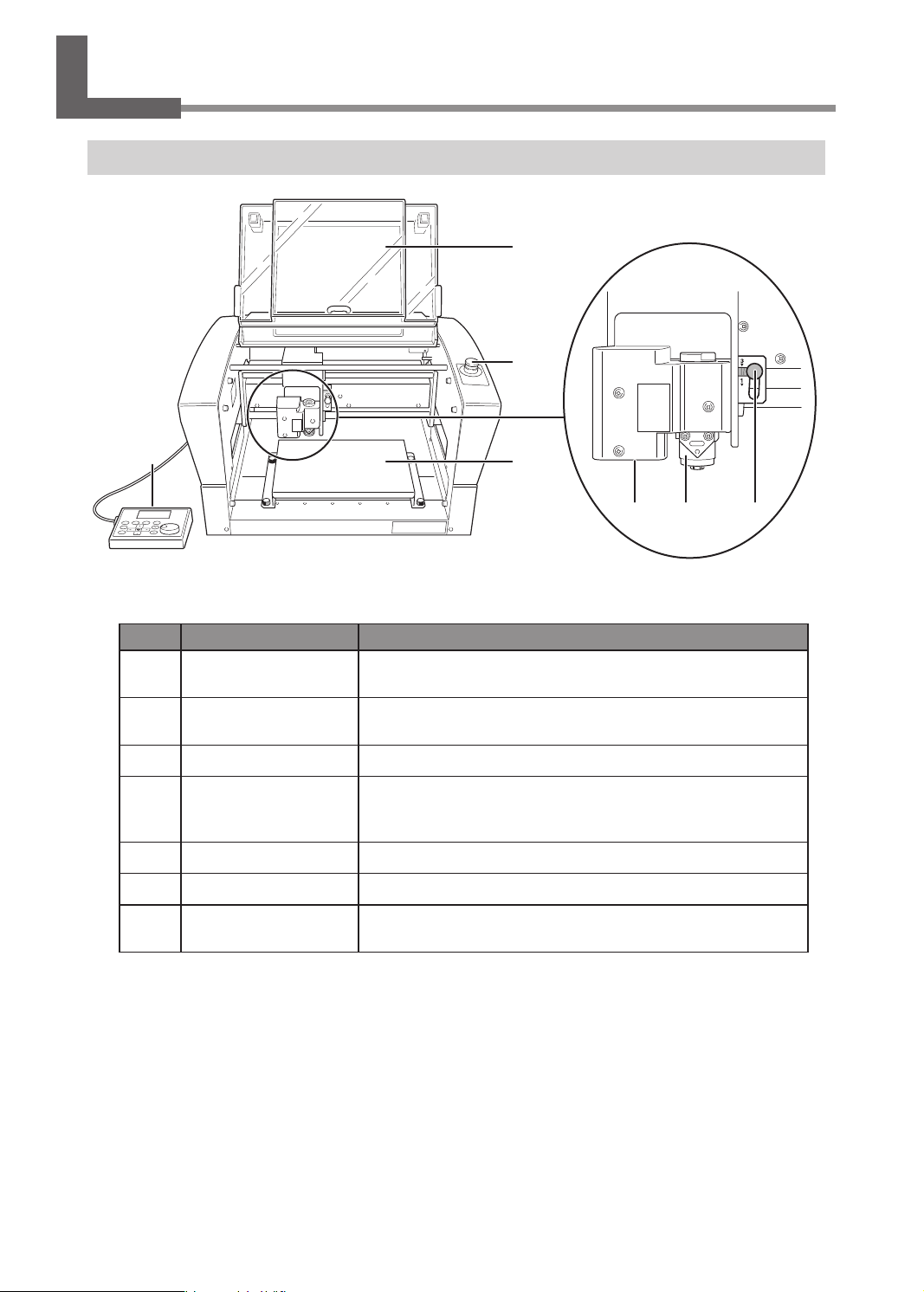
Part Names and Functions
Front and Interior
1
2
3
Spindle head*
546 7
* In this document, the mechanisms around the spindle unit, including the spindle motor, are called the
"spindle head." Also, the rotary-axis area inside the spindle unit is called the "spindle."
No. Part Overview
1
2
3
4
5
6
7
Front cover
Emergency stop button
Workpiece table The workpiece to be engraved is mounted on this table.
Handy Panel
Laser pointer Laser irradiation is applied from here.
Spindle unit Install the tool here.
Lock lever
To ensure safety, opening this during engraving or spindle rotation
causes an emergency stop to occur.
Press this in an emergency to interrupt this machine's power supply.
" P. 13 “Emergency Stop to Ensure Safety”
This is used to perform tool movement and other machine
operations, and to make various settings.
" P.8 “Handy Panel”
This locks or unlocks the spindle head.
" P. 62 “Setting the Lock Lever”
6
Chapter 1 Getting Started
Page 9
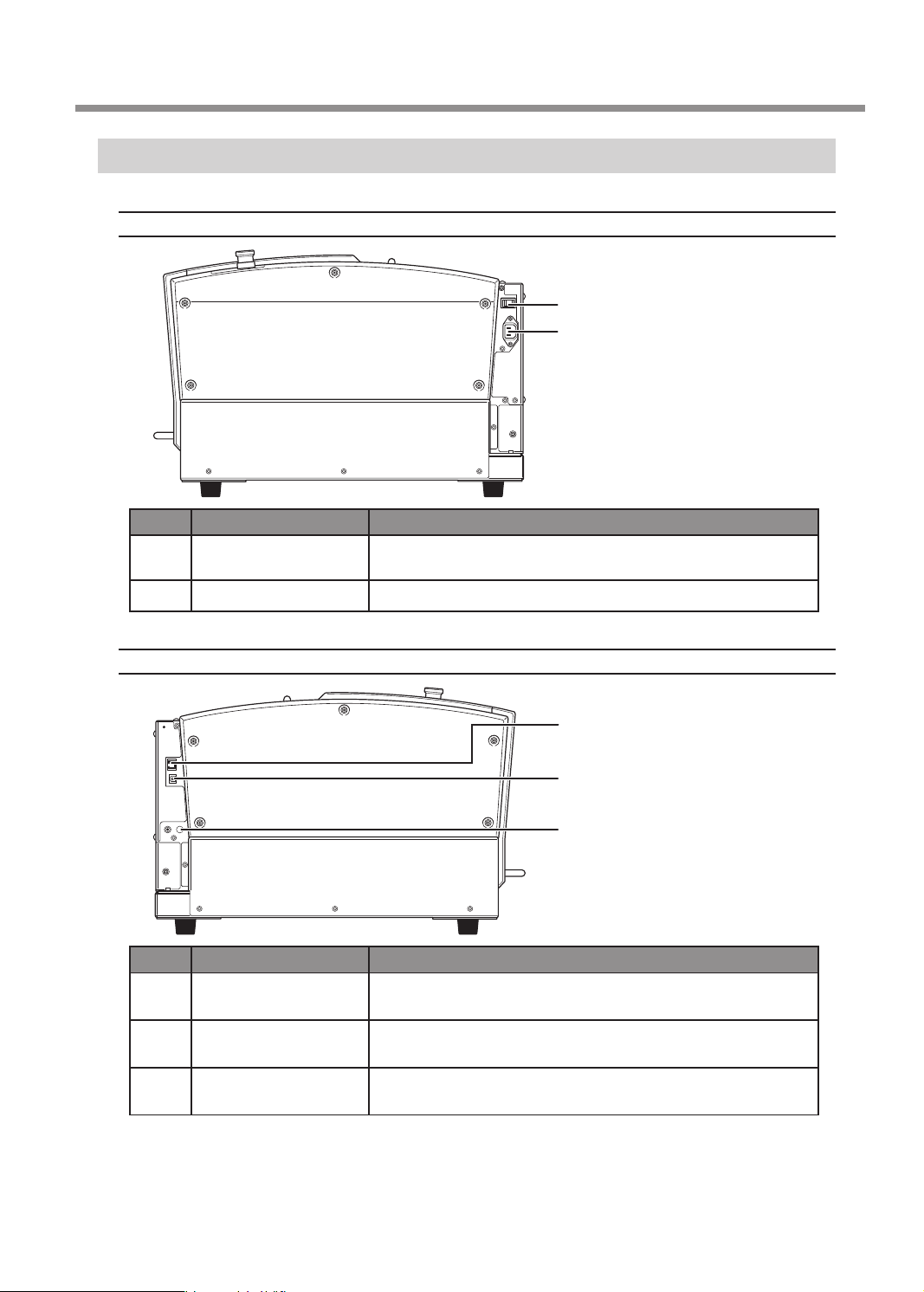
Side
Right Side
No. Part Overview
1
2
Power switch
Power cord connector This is for connecting a power cord.
This switches this machine's power on or off.
" P.16 “Switching the Power On or Off”
Part Names and Functions
1
2
Left Side
3
4
5
No. Part Overview
3
4
5
LAN connector
USB connector
Expansion port
This is for connecting a LAN cable.
" Setup Guide "Connecting the LAN Cable"
This is for connecting a USB cable.
" Setup Guide "Connecting the USB Cable"
This is a connector for external equipment.
" P. 152 “Expansion Port”
Chapter 1 Getting Started
7
Page 10
Part Names and Functions
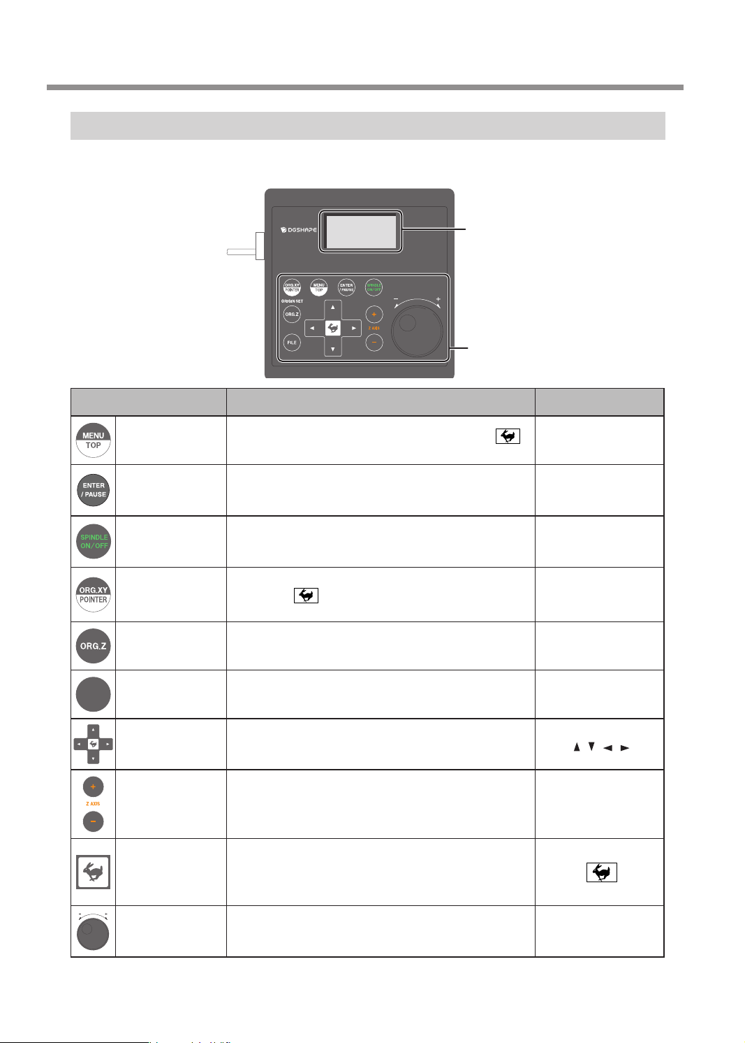
Handy Panel
This is used to perform tool movement and other machine operations, and to make various settings. Close the
front cover, then perform the operation of the handy panel.
Display screen
Menus, messages, etc. are displayed here.
" P.9 “Viewing the Handy Panel Screen”
Operation button
For details, see table below.
Operation button Functional overview
Pressing this changes the menu screen. Hold down
and press this button to return to the main screen.
This executes a selected on-screen item or conrms a
selected item or value. Pressing this during engraving
pauses operation and displays the PAUSE menu.
Holding this down for one second or longer while the
spindle is stopped makes spindle rotation start. Pressing
this during spindle rotation stops rotation.
This sets the reference point for the engraving position.
Hold down
off the irradiation from the laser pointer.
This sets the reference point for the engraving position. [ORG.Z]
These move the tool forward and backward, and to the left
and right.
These move the tool up and down.
and press this button to switch on and
FILE
Menu/Top
Enter/Pause
Spindle
X/Y-axis Origin
Setting/Laser
Pointer
Z-axis Origin
Setting
File Operates the data in the memory of this machine. [FILE]
Move
Z-axis
Movement
Notation used in this
document
[MENU/TOP]
[ENTER/PAUSE]
[SPINDLE]
[ORG.XY/POINTER]
[
] [ ] [ ] [ ]
[+Z]
[-Z]
Pressing a Movement or Z-axis Movement button while
Feed/Shift
Dial
8
Chapter 1 Getting Started
holding down this button makes the tool move rapidly. This
is also used as a shift key by pressing it at the same time
as other buttons.
This adjusts the movement of the tool and the number of
rotations of the spindle. You use this to select items and
change settings on the menu screen.
[Dial]
Page 11
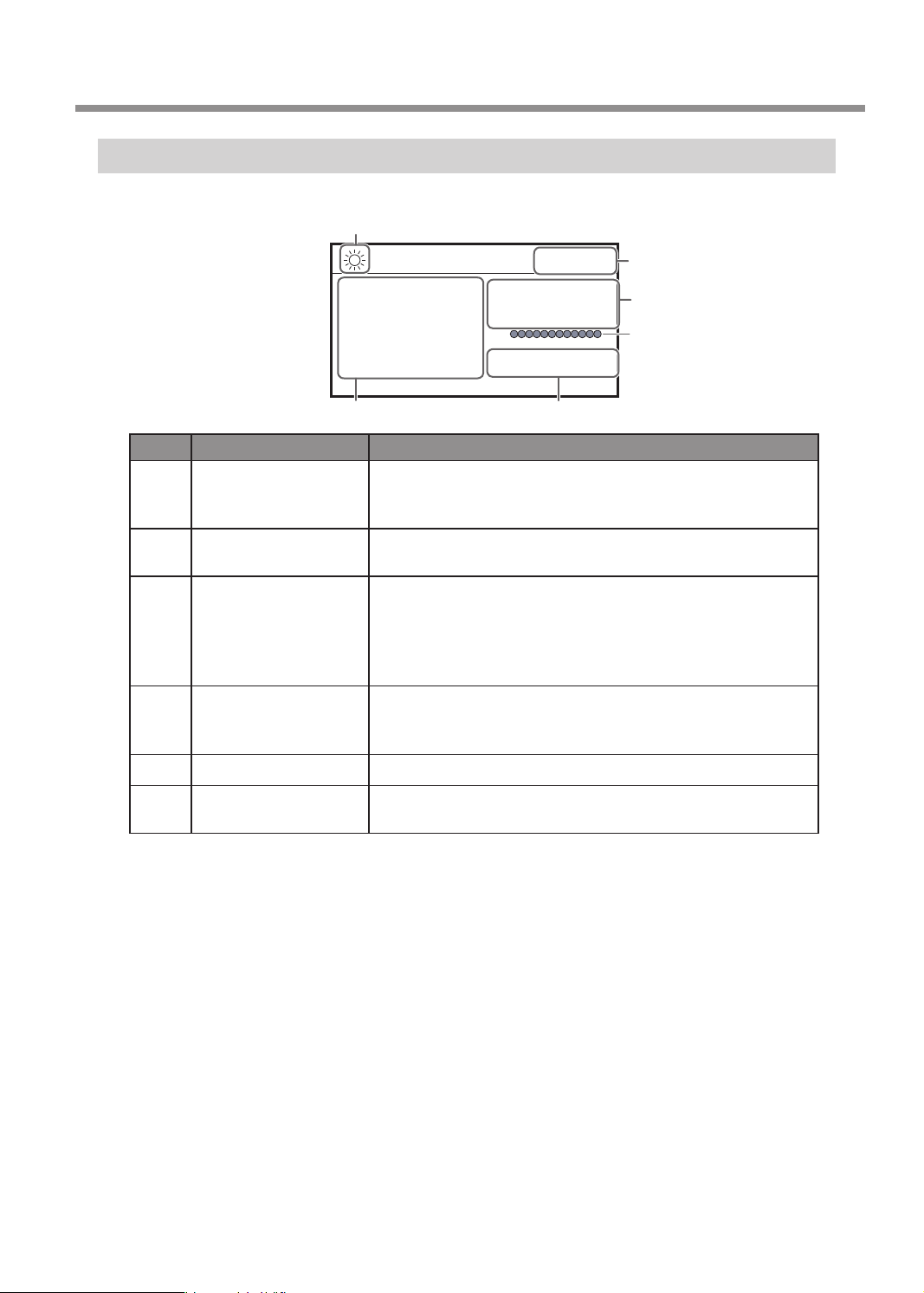
Viewing the Handy Panel Screen
(Main screen)
1
Part Names and Functions
012345678901234567 READY
X 50.00mm
Y 30.00mm
XYZ 100%
S 100%
Z 20.00mm S 5000rpm
3
No. Part Overview
When the laser pointer function is turned on, this icon appears. When
1
2
3
4
5
6
Laser pointer on/off
Status display
Current values of the
tool/laser pointer
Override
Spindle load Indicates the increase in load as the gauge increases to the right.
Number of rotations
of the spindle
the laser pointer function is turned on, the current values of the laser
pointer are displayed on the handy panel.
Displays the status of the machine such as [READY], [BUSY], and
[PAUSE].
When the laser pointer function is off, this displays the current values
of the tool seen from the user origin. When the laser pointer function
is on, this displays the current values of the laser pointer seen from
the user origin.
" P. 39 “Step 2: Setting the XY Origin”
Displays the ratio of change (unit: %) relative to the present feeding
speed (XYZ) and the spindle rotating speed (S). The override setting
is only displayed during engraving.
Displays the number of spindle rotations per minute.
6
2
4
5
Chapter 1 Getting Started
9
Page 12
зыъхЖĀЖщлъъпфнЖЖЖЖЖЖЖЖЖЖЖЖЖЖЖЖЖЖЖ
кпщъзфйлЖйхшшлйъпхфЖЖЖЖЖЖЖЖЖЖЖЖЖЖЖЖЖЖЖ
тзщлшЖйхшшлйъпхфЖЖЖЖЖЖЖЖЖЖЖЖЖЖЖЖЖЖ
MAC 00:00:00:00:00:00
пфмхшузъпхфЖЖЖЖЖЖЖЖЖЖЖЖЖЖЖЖЖЖЖ
пфмхшузъпхфЖЖЖЖЖЖЖЖЖЖЖЖЖЖЖЖЖЖЖ
пфмхшузъпхфЖЖЖЖЖЖЖЖЖЖЖЖЖЖЖЖЖЖЖ
пфмхшузъпхфЖЖЖЖЖЖЖЖЖЖЖЖЖЖЖЖЖЖЖ
пфмхшузъпхфЖЖЖЖЖЖЖЖЖЖЖЖЖЖЖÆÆÆÆ
Жпфмхшузъпхф
ЖузйопфлЖхшпнпфЖюя
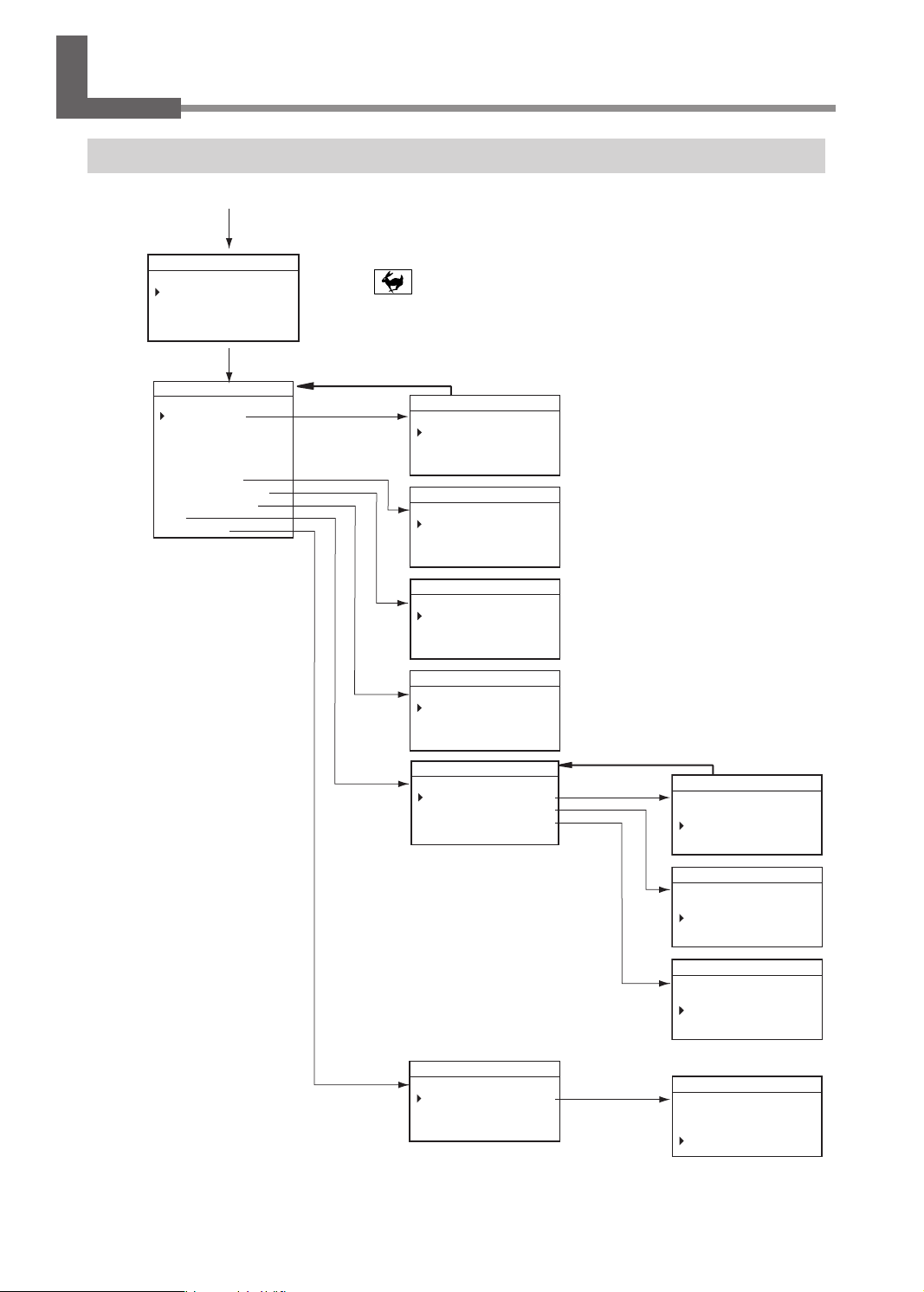
Menu List
Main Menu
Main screen
[MENU]
ЦЧШЩЪЫЬЭЮЯЦЧШЩЪЫЬЭЖшлзкя
ухьлЖЖЖЖЖЖЖЖЖЖЖЖЖЖЖЖЖЖЖЖ
ЖьплэЖцхщпъпхф
Жйлфълш
ЖыщлшЖхшпнпфЖюя
[MENU]
ЦЧШЩЪЫЬЭЮЯЦЧШЩЪЫЬЭЖшлзкя
щлъъпфнщЖЖЖЖЖЖЖЖЖЖЖЖЖ
ЖхцлшзъпфнЖухкл
ЖщцпфктлЖшльхтыъпхфЖЖЖхф
ЖзыъхЖĀЖйхфъшхтЖЖЖЖЖЖхмм
ЖхьлшЖзшлзЖЖЖЖЖЖйхфъпфыл
ЖщъзшъЖулщщзнлЖЖЖЖЖЖЖЖхф
ЖзыъхЖĀЖщлъъпфн
ЖкпщъзфйлЖйхшшлйъпхф
ЖтзщлшЖйхшшлйъпхф
Жтзф
Turn the [Dial] to move the cursor on the screen or change the setting values.
* Press + [MENU] to return to the main screen.
" P.20
Press [MENU] to return to the
previous screen.(*)
[ENTER]
ЦЧШЩЪЫЬЭЮЯЦЧШЩЪЫЬЭЖшлзкя
хцлшзъпфнЖухкл
Жйыъ
ЖцшльплэЖцзъо
ЖцшльплэЖзшлзЖЖЖЖЖЖЖЖЖЖ
ЦЧШЩЪЫЬЭЮЯЦЧШЩЪЫЬЭЖшлзкя
ЖыцЖЖЖЫФЦЦĒĒ
" P.63
" P.64
ЦЧШЩЪЫЬЭЮЯЦЧШЩЪЫЬЭЖшлзкя
ЖюЖЖЧЦЦФЦЦЛ
ЖяЖЖЧЦЦФЦЦЛ
" P.75
ЦЧШЩЪЫЬЭЮЯЦЧШЩЪЫЬЭЖшлзкя
ЖюЖЖЖЦЦФЦЦĒĒ
ЖяЖЖЖЦЦФЦЦĒĒ
012345678901234567 READY
LAN
IP 192.168.001.254
SUBNET 255.255.255.000
GATEWAY 000.000.000.000
" P.75
[ENTER]
Press [MENU] to return to the
previous screen.(*)
012345678901234567 READY
IP
192 . 168 . 001 . 254
" Setup Guide
012345678901234567 READY
SUBNET
255 . 255 . 255 . 000
10
Chapter 1 Getting Started
[ENTER]
ЦЧШЩЪЫЬЭЮЯЦЧШЩЪЫЬЭЖшлзкя
ЦЧШЩЪЫЬЭЮЯЦЧШЩЪЫЬЭЖшлзкя
ЦЧШЩЪЫЬЭЮЯЦЧШЩЪЫЬЭЖшлзкя
ЦЧШЩЪЫЬЭЮЯЦЧШЩЪЫЬЭЖшлзкя
ЦЧШЩЪЫЬЭЮЯЦЧШЩЪЫЬЭЖшлзкя
ЖщцпфктлЖыфпъЖЖЖЧЯЯЯčЫЦĒ
ЖщцпфктлЖыфпъЖЖЖЧЯЯЯčЫЦĒ
ЖщцпфктлЖыфпъЖЖЖЧЯЯЯčЫЦĒ
ЖщцпфктлЖыфпъЖЖЖЧЯЯЯčЫЦĒ
ЖщцпфктлЖыфпъЖЖЖЧЯЯЯčЫЦĒ
ЖъхъзтЖэхшсЖЖЖЖЖШШЫЦčШЦĒ
ЖъхъзтЖэхшсЖЖЖЖЖШШЫЦčШЦĒ
ЖъхъзтЖэхшсЖЖЖЖЖШШЫЦčШЦĒ
ЖъхъзтЖэхшсЖЖЖЖЖШШЫЦčШЦĒ
ЖъхъзтЖэхшсЖЖЖЖЖШШЫЦčШЦĒ
" P.71
012345678901234567 READY
GATEWAY
000 . 000 . 000 . 000
ЦЧШЩЪЫЬЭЮЯЦЧШЩЪЫЬЭЖREADY
SPINDLE UNIT
ЖэхшсЖъпулЖЖЖЖЖЖЧЯЯЯčЫЦĒ
OK Clear
Page 13
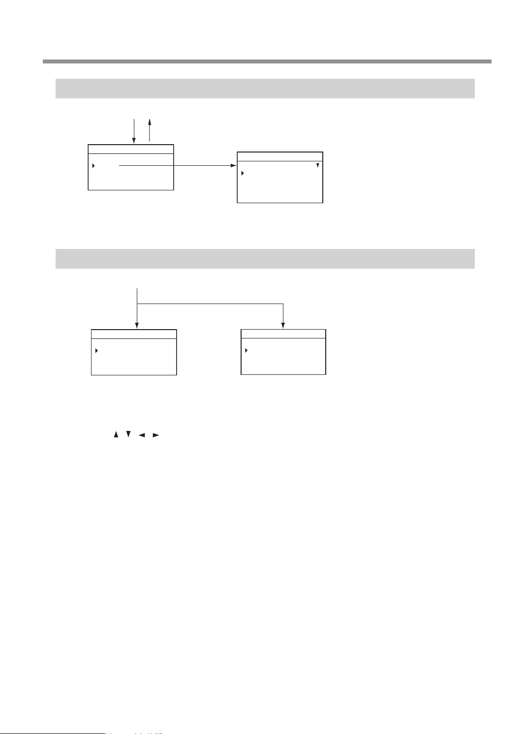
File Menu
мптлЖхцлшзъпхфЖЖЖЖЖЖЖЖЖЖЖЖЖЖЖЖЖЖЖ
ORIGIN SET Z
Main screen
Menu List
[FILE]
ЦЧШЩЪЫЬЭЮЯЦЧШЩЪЫЬЭЖшлзкя
мптлЖЖЖЖЖЖЖЖЖЖЖЖЖЖЖЖЖЖЖ
Жйхця
[MENU]
Origin-setting Menu
Main screen
[ORG.XY]
ЦЧШЩЪЫЬЭЮЯЦЧШЩЪЫЬЭЖREADY
ORIGIN SET XY
ЖюяƄƄƄƄюƄƄƄƄя
ЖЖюƄЩЮФЮЮĒĒ
ЖЖяЖЖЧЭФЦЦĒĒ
" P.39
ЦЧШЩЪЫЬЭЮЯЦЧШЩЪЫЬЭЖшлзкя
ЖщъзшъЖйыъъпфн
ЖщъзшъЖцшльплэЖцзъо
ЖщъзшъЖцшльплэЖзшлз
Жклтлъл
" P.123
[ORG.Z]
012345678901234567 READY
Z0
Z -30.00mm
" P.100
" P.108
• Turn the [Dial] to move the cursor on the screen.
• Use [ ], [ ], [ ], [ ], [+Z], and [−Z] to change the settings.
• Press [MENU] to return to the main screen.
Chapter 1 Getting Started
11
Page 14

Chapter 2 Basic Operation
Emergency Stop to Ensure Safety .............................................................................................. 13
How to Perform an Emergency Stop ............................................................................. 13
Canceling an Emergency Stop.........................................................................................13
Switching the Power On or O .................................................................................................... 16
Switching the Power On ....................................................................................................16
Switching the Power O ....................................................................................................17
Moving the Tool ................................................................................................................................ 18
Terms of Tool Position ......................................................................................................... 18
Display Example of Tool Position ....................................................................................18
Moving to the Desired Position .......................................................................................19
Moving to the Specied Position ...................................................................................20
Pausing and Aborting ..................................................................................................................... 21
Pausing and Resuming Engraving .................................................................................21
Aborting Engraving ............................................................................................................. 23
12
Chapter 2 Basic Operation
Page 15
Emergency Stop to Ensure Safety
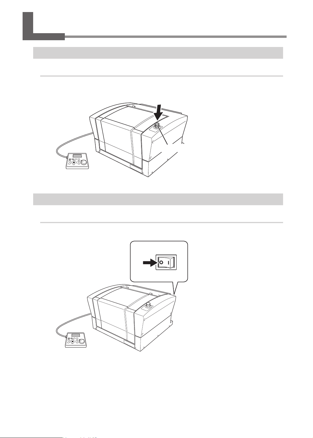
How to Perform an Emergency Stop
Procedure
Press the emergency stop button.
Operation stops immediately.
Emergency stop button
Canceling an Emergency Stop
Procedure
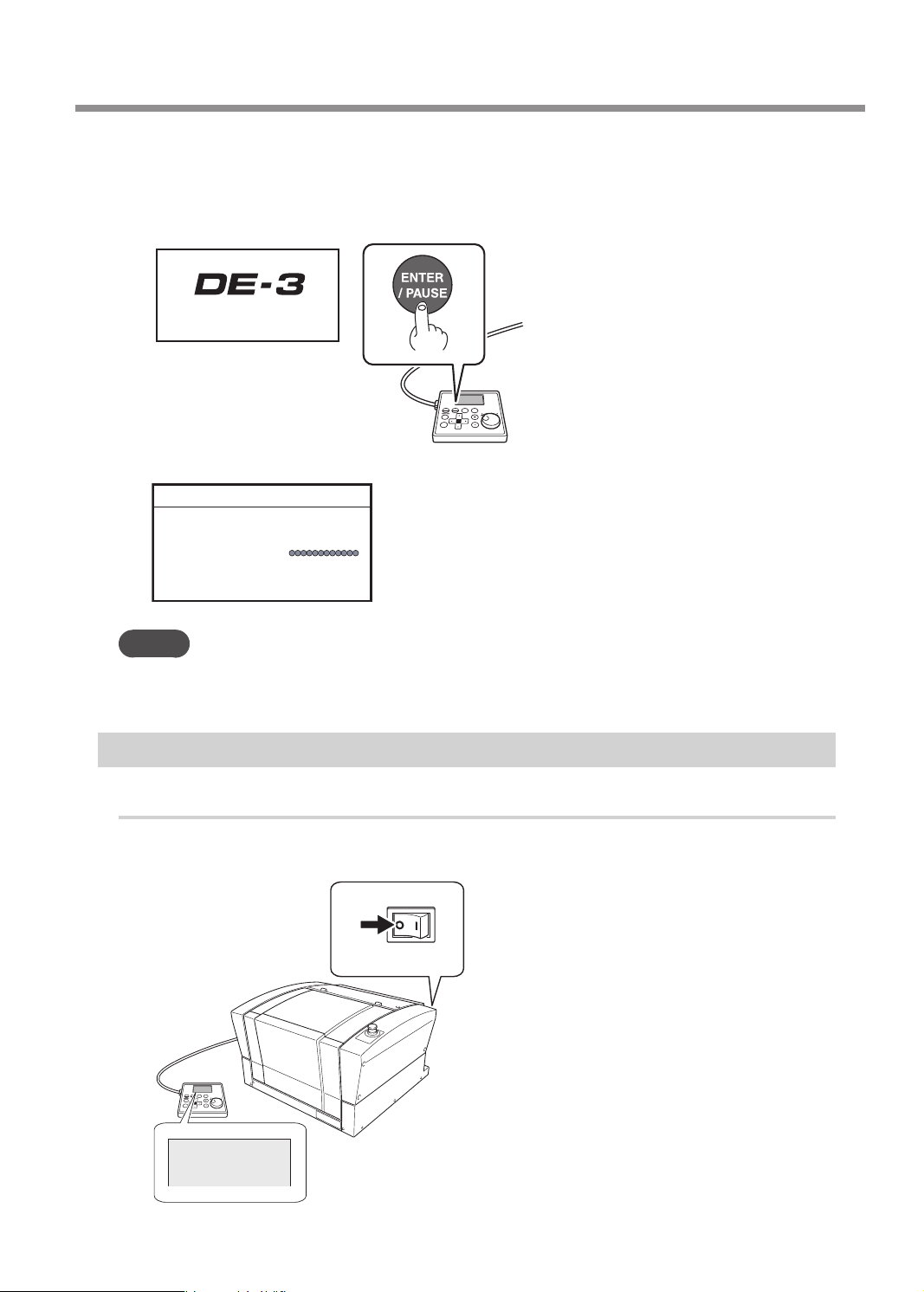
Switch off the power switch.
A
OFF
Chapter 2 Basic Operation
13
Page 16
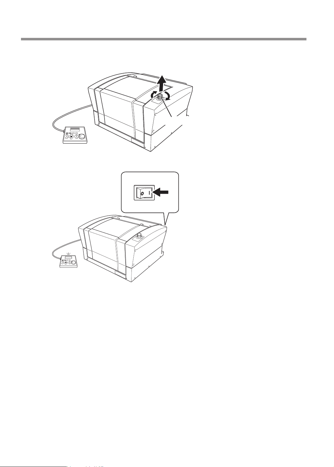
Emergency Stop to Ensure Safety
Turn the button in the direction of the arrows.
B
The button goes up, and the emergency stop is canceled.
Switch on the power switch.
C
Emergency stop button
ON
14
Chapter 2 Basic Operation
Page 17
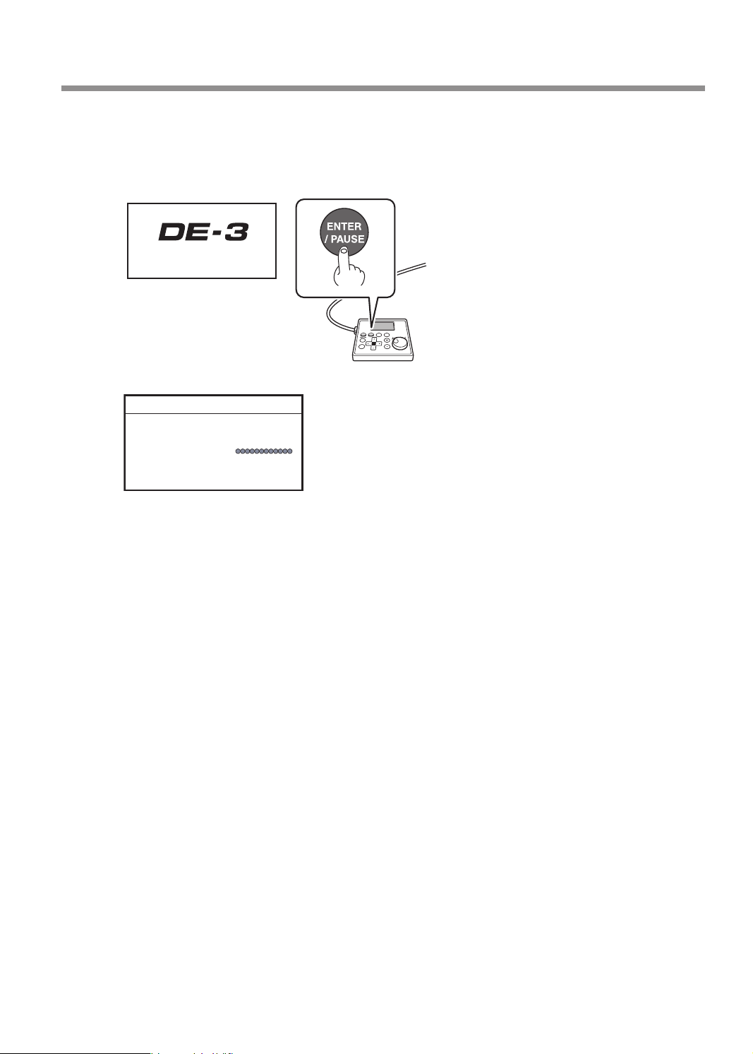
Emergency Stop to Ensure Safety
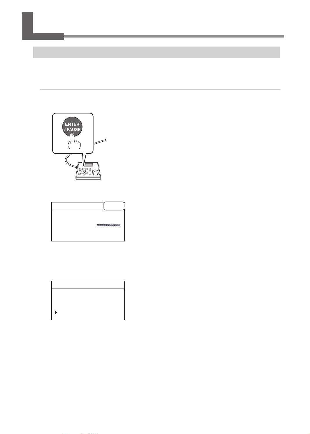
When the screen shown below appears after approximately three seconds, press [ENTER/
D
PAUSE].
The spindle head moves to the left of the back of this machine (this movement at the machine's startup
is called the "initial operation").
Hit [ENTER] key.
Vxxx
* "XXX" indicates the version
number of the machine's
rmware.
When the initial operation is complete, the main screen appears.
012345678901234567 READY
X 15.00mm
Y 23.00mm
Z 0.00mm S 5000rpm
Chapter 2 Basic Operation
15
Page 18
Switching the Power On or Off
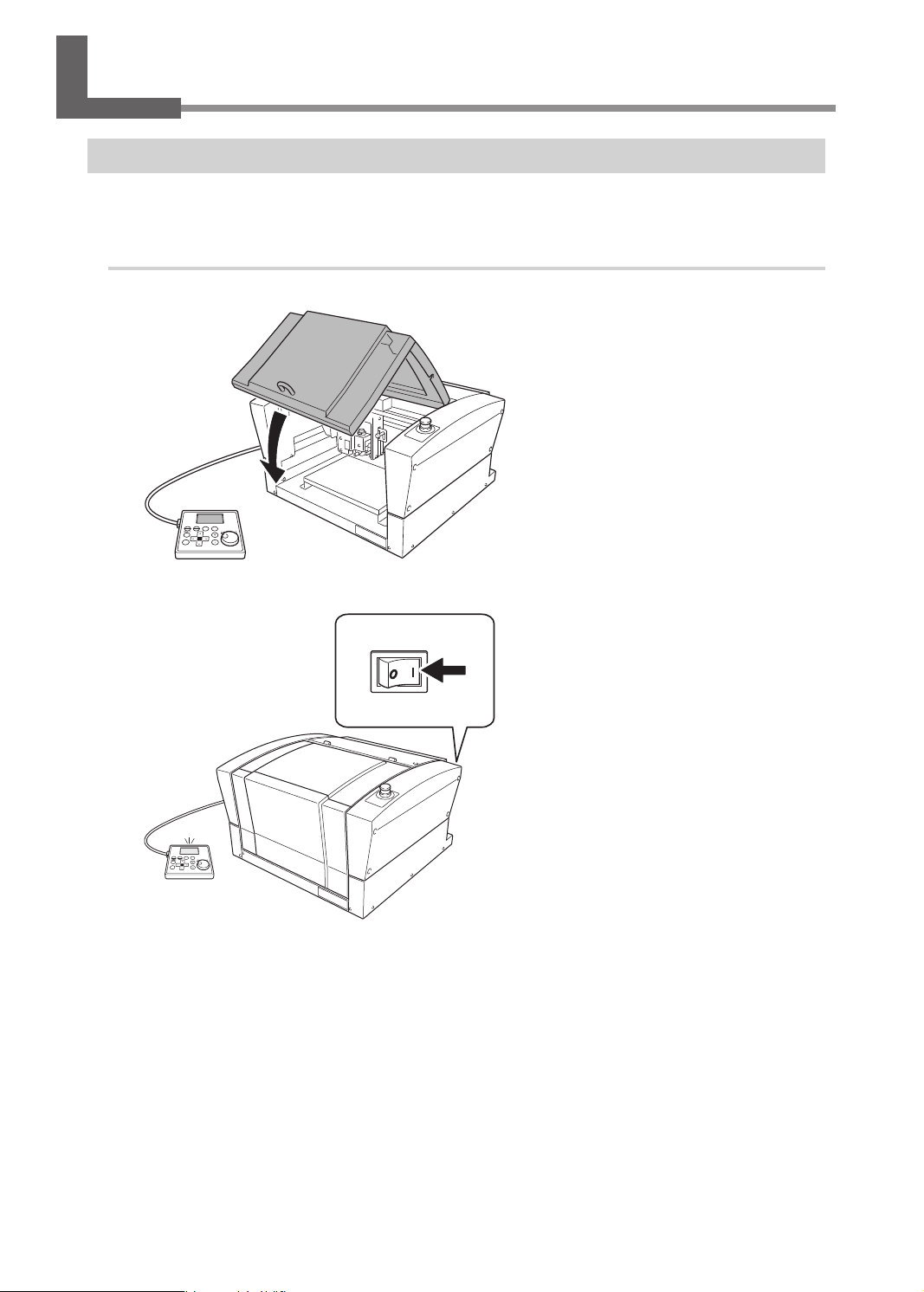
Switching the Power On
When the machine is connected to a computer, install the driver, and then turn on the power.
" Setup Guide "Installing the Software"
Procedure
Close the front cover.
A
Switch on the power switch.
B
ON
16
Chapter 2 Basic Operation
Page 19
Switching the Power On or Off
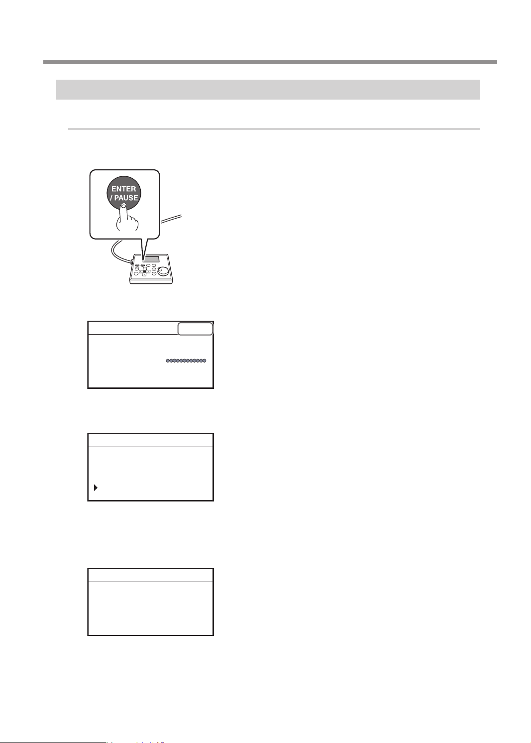
When the screen shown below appears after approximately three seconds, press [ENTER/
C
PAUSE].
The spindle head moves to the left of the back of this machine (this movement at the machine's startup
is called the "initial operation").
Hit [ENTER] key.
Vxxx
* "XXX" indicates the version
number of the machine's
rmware.
When the initial operation is complete, the following screen appears.
012345678901234567 READY
X 15.00mm
Y 23.00mm
Z 0.00mm S 5000rpm
MEMO
The factory default setting for the language used for on-screen display is English. For the method to
change the display language to Japanese, see the Setup Guide.
Switching the Power Off
Procedure
Make sure the machine is not in operation, then turn off the power switch.
The display screen on the handy panel goes dark.
OFF
O
Chapter 2 Basic Operation
17
Page 20
XYZ 100%
X 35.00mm
01234567890123456 待機中
Moving the Tool
Terms of Tool Position
This manual uses the following terms to indicate the position of the tool.
Terms Overview
These refer to the numerical values that indicate the position of the tool on each of the X/Y/Z axis. They are represented
along with the axis, and the values are represented as positive or negative numbers.
(Representation)
Coordinates
The following are the two types of coordinates.
• "Machine coordinates": Coordinates whose origin is a machine-specic origin (machine origin) that
cannot be changed.
• "User coordinates": Coordinates whose origin is an origin that can be changed by the user (user origin).
Origin This refers to the origin ("0" position) of coordinates.
X-axis
coordinate
Y-axis
coordinate
Z-axis
coordinate
This refers to the distance from the origin of the X
axis direction (horizontal direction when the table is
seen from directly above).
This refers to the distance from the origin of the Y
axis direction (vertical direction when the table is
seen from directly above).
This refers to the distance from the origin of the Z
axis direction (height direction).
Axis Distance from the origin
Display Example of Tool Position
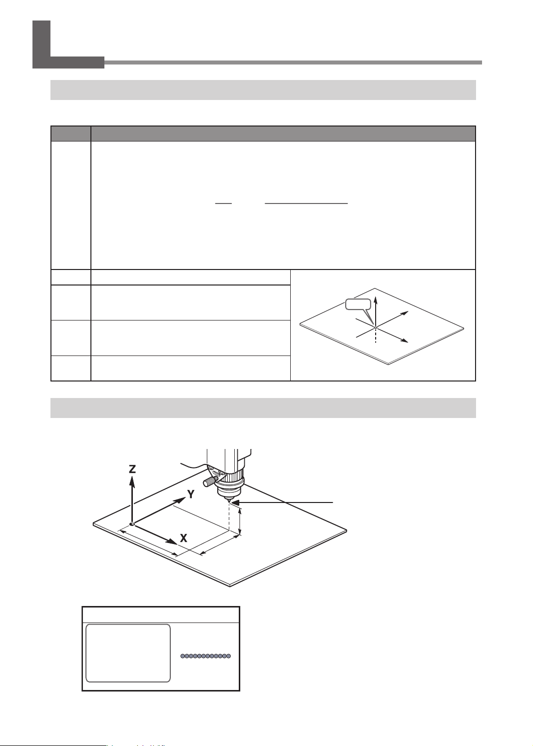
¾ When the tool has moved from the origin by 50 mm (2.0 in.) along the X axis, 30 mm (1.2 in.) along the Y
axis, and 20 mm (0.8 in.) along the Z axis.
Origin
Z
Y
X
Origin
50 mm (2.0 in.)
This tool position is displayed on the handy panel's main screen as shown below.
20 mm (0.8 in.)
30 mm (1.2 in.)
012345678901234567 READY
X 50.00mm
Y 30.00mm
Z 20.00mm S 5000rpm
18
Chapter 2 Basic Operation
Actual tool position
Page 21
ORIGIN SET Z
Moving the Tool
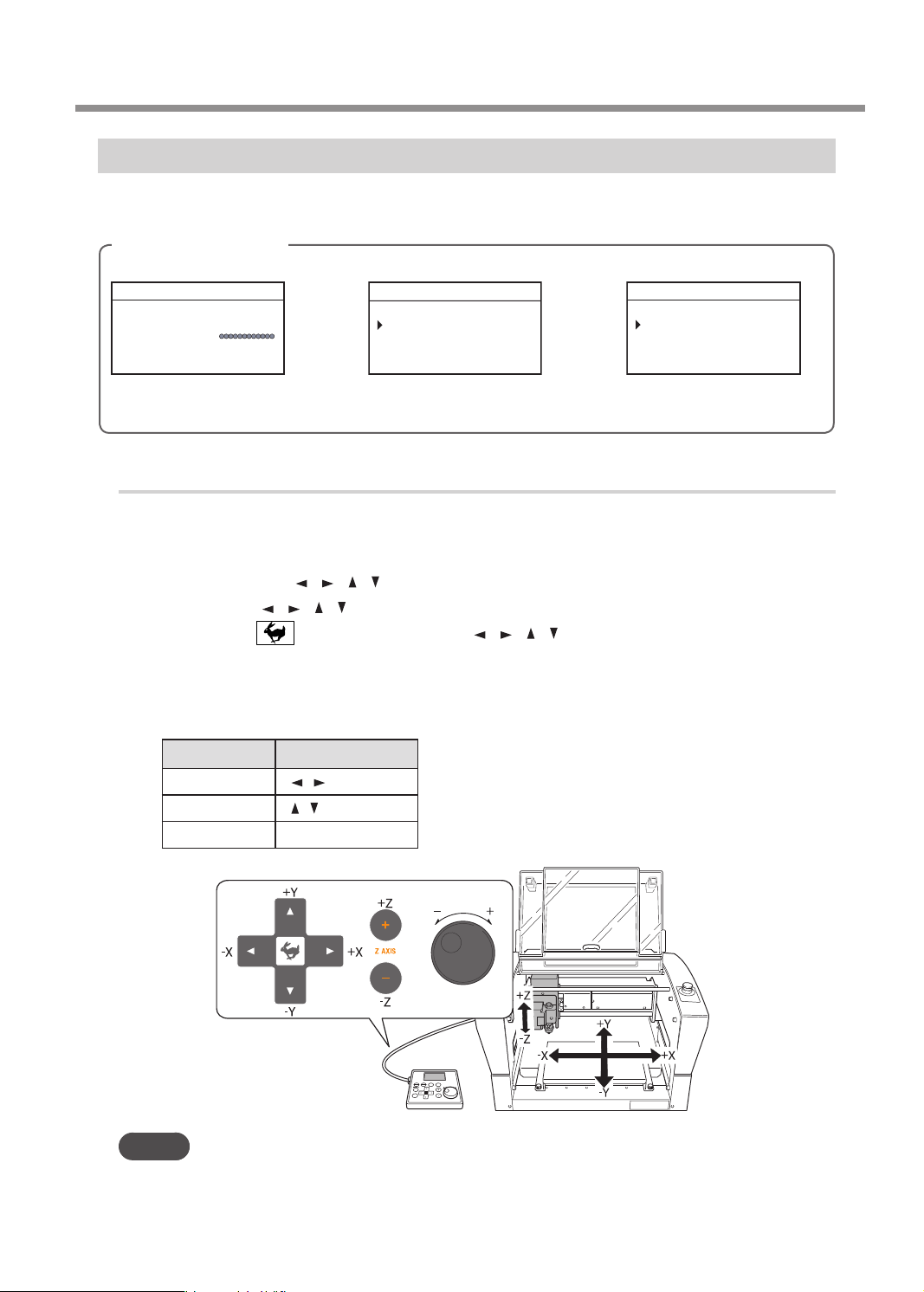
Moving to the Desired Position
When the screens shown below are displayed on the handy panel, you can move the tool manually using the
[Dial] or the Movement buttons.
Screens on the handy panel
Main screen
012345678901234567 READY
X 15.00mm
Y 23.00mm
Z 0.00mm S 5000rpm
Movement along the X, Y, and
Z axes with the [Dial] or
Movement buttons
When setting the XY origin
012345678901234567 READY
ORIGIN SET XY
XY X Y
X 38.88mm
Y 17.00mm
Movement along the X and
Y axes only with the
Movement buttons
Procedure
Close the front cover and press [ENTER/PAUSE].
A
Press the Movement buttons or turn the [Dial].
B
• Each single press of [
• Holding down [
• Holding down while pressing and holding [ ], [ ], [ ], [ ], [+Z], or [-Z] performs rapid continuous
movement.
• Turning the [Dial] performs movement by 0.01 mm (0.0004 in.) at a time.
The cursor moves to a dierent axis on the screen on the handy panel. You can change the axis to move by
pressing the Movement buttons in advance.
], [ ], [ ], [ ], [+Z], or [-Z] performs movement by 0.01 mm (0.0004 in.).
], [ ], [ ], [ ], [+Z], or [-Z] performs slow continuous movement.
When setting the Z origin
012345678901234567 READY
Z0
Z -30.00mm
Movement along the Z axis
only with the Movement
buttons
Axis to move Movement buttons
MEMO
This operation cannot be performed while the front cover is open.
[
X
Y
Z
] [ ]
] [ ]
[
[+Z] [−Z]
Chapter 2 Basic Operation
19
Page 22
Moving the Tool
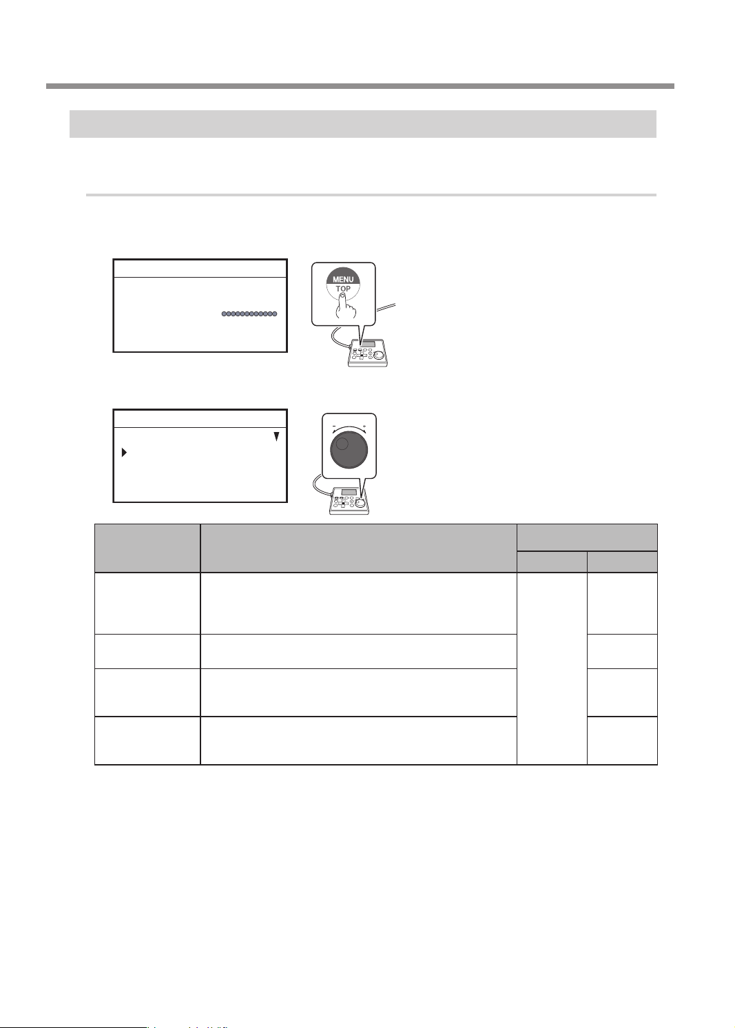
Moving to the Specied Position
The spindle head automatically moves to the predetermined position through the operation of the handy panel.
Procedure
Close the front cover and press [ENTER/PAUSE].
A
On the main screen, press [MENU/TOP].
B
012345678901234567 READY
X 15.00mm
Y 23.00mm
Z 0.00mm S 5000rpm
Turn the [Dial] and select the movement destination.
C
012345678901234567 READY
MOVE
VIEW POSITION
CENTER
USER ORIGIN XY
Target for moving to a
MENU Movement position explanation
This is the left-back position on the workpiece table. You
VIEW POSITION
CENTER
USER ORIGIN XY
MACHINE ORIGN
XY
* LP: Laser pointer
Press [ENTER/PAUSE].
D
When movement by this operation is performed, to avoid contact with the workpiece, the tool or laser
pointer rst rises to the highest point along the Z axis, and then moves to the selected position.
Press [MENU/TOP] several times to return to the main screen.
E
use it in situations such as when mounting or removing a
workpiece, or when checking the state of the workpiece. In
this manual, this position is called the "view position."
This is the center position on the workpiece table. Use this
function when replacing the tool, cleaning the spindle unit, etc.
This is the location where the X- and Y-axis coordinates are "0"
in the user coordinates. This XY origin point can be changed.
" P. 39 “Setting the XY Origin”
This is the location where the X- and Y-axis coordinates are
both "0" in machine coordinate. This XY origin point is xed
for this machine and cannot be changed.
specied location
LP OFF LP ON
Tool tip
Tool tip
LP
LP
LP
20
Chapter 2 Basic Operation
Page 23
Pausing and Aborting
Pausing and Resuming Engraving
This pauses engraving through operation using the handy panel. This also makes it possible to resume engraving
at the paused position after an operation such as moving the tool to check the status of the workpiece.
Procedure
While operation is in progress, press [ENTER/PAUSE].
A
The tool moves to the upper limit of the Z axis, and then rotation stops.
The following window is displayed.
" P. 22 "When Checking the Status of the Workpiece by Moving the Tool"
012345678901234567 PAUSE
X 15.00mm
Y 23.00mm
XYZ 100%
S 100%
Z 0.00mm S 5000rpm
If the front cover is open, close it, and then press [ENTER/PAUSE].
B
Press [ENTER/PAUSE].
C
The following window is displayed.
012345678901234567 PAUSE
Resume cutting?
Yes No CancelJob
Turn the [Dial] and select [Yes].
D
Press [ENTER/PAUSE] to conrm.
E
The main screen appears again and engraving resumes.
Chapter 2 Basic Operation
21
Page 24

Pausing and Aborting
When Checking the Status of the Workpiece by Moving the Tool
Procedure
Press [MENU/TOP] several times to display the following screen.
A
012345678901234567 PAUSE
MOVE
VIEW POSITION
CENTER
USER ORIGIN XY
Select [VIEW POSITION] using the [Dial].
B
Press [ENTER/PAUSE] to conrm.
C
The tool moves to the view position at the left side of the back.
" P. 20 "Moving to the Specied Position"
Press [MENU/TOP] several times to return to the main screen.
D
The main screen in the paused state appears again.
012345678901234567 PAUSE
X 15.00mm
Y 23.00mm
XYZ 100%
S 100%
Z 0.00mm S 5000rpm
22
Chapter 2 Basic Operation
Page 25
Aborting Engraving
Procedure
While operation is in progress, press [ENTER/PAUSE].
A
The tool moves to the upper limit of the Z axis, and then rotation stops.
The following window is displayed.
" P. 22 "When Checking the Status of the Workpiece by Moving the Tool"
012345678901234567 PAUSE
X 15.00mm
Y 23.00mm
XYZ 100%
S 100%
Z 0.00mm S 5000rpm
Pausing and Aborting
Press [ENTER/PAUSE].
B
The following window is displayed.
012345678901234567 PAUSE
Resume cutting?
Yes No CancelJob
Turn the [Dial] and select [CancelJob].
C
Press [ENTER/PAUSE] to conrm.
D
The following window is displayed.
34567890123 CANCELING
Canceling cutting.
Wait a moment please...
Chapter 2 Basic Operation
23
Page 26

Chapter 3 Basic Engraving Methods
Checks and Preparation before Engraving..............................................................................25
Checking the Flow of Engraving Operation ...............................................................25
Checking Engravable Workpieces .................................................................................. 26
Determining the Item to Create and Required Material and Tool ...................... 27
Creating Engraving Data................................................................................................................28
Step 1: Starting Dr. Engrave Plus .....................................................................................28
Step 2: Creating a Shape .................................................................................................... 30
Step 3: Loading an Image .................................................................................................. 31
Step 4: Entering Text ............................................................................................................ 33
Step 5: Setting the Engraving Parameters ...................................................................35
Step 6: Saving Engraving Data.........................................................................................37
Starting Engraving ........................................................................................................................... 38
Step 1: Setting the Workpiece .........................................................................................38
Step 2: Setting the XY Origin ............................................................................................ 39
Step 3: Installing a Character Cutter/Parallel Cutter ................................................41
Step 4: Checking the Engraving Parameters ..............................................................51
Step 5: Starting Engraving ................................................................................................ 54
Other Basic Operations .................................................................................................................. 56
Adjusting the Tool Feeding Speed and the Number of Rotations
during Engraving (Override) ............................................................................................ 56
Attaching the Vacuum Adapter ....................................................................................... 58
Setting the Lock Lever ........................................................................................................ 62
Changing the Operation Mode ....................................................................................... 63
Setting the Avoidance Height of the Tool to Match the Workpiece Shape ..... 64
24
Chapter 3 Basic Engraving Methods
Page 27
Checks and Preparation before Engraving
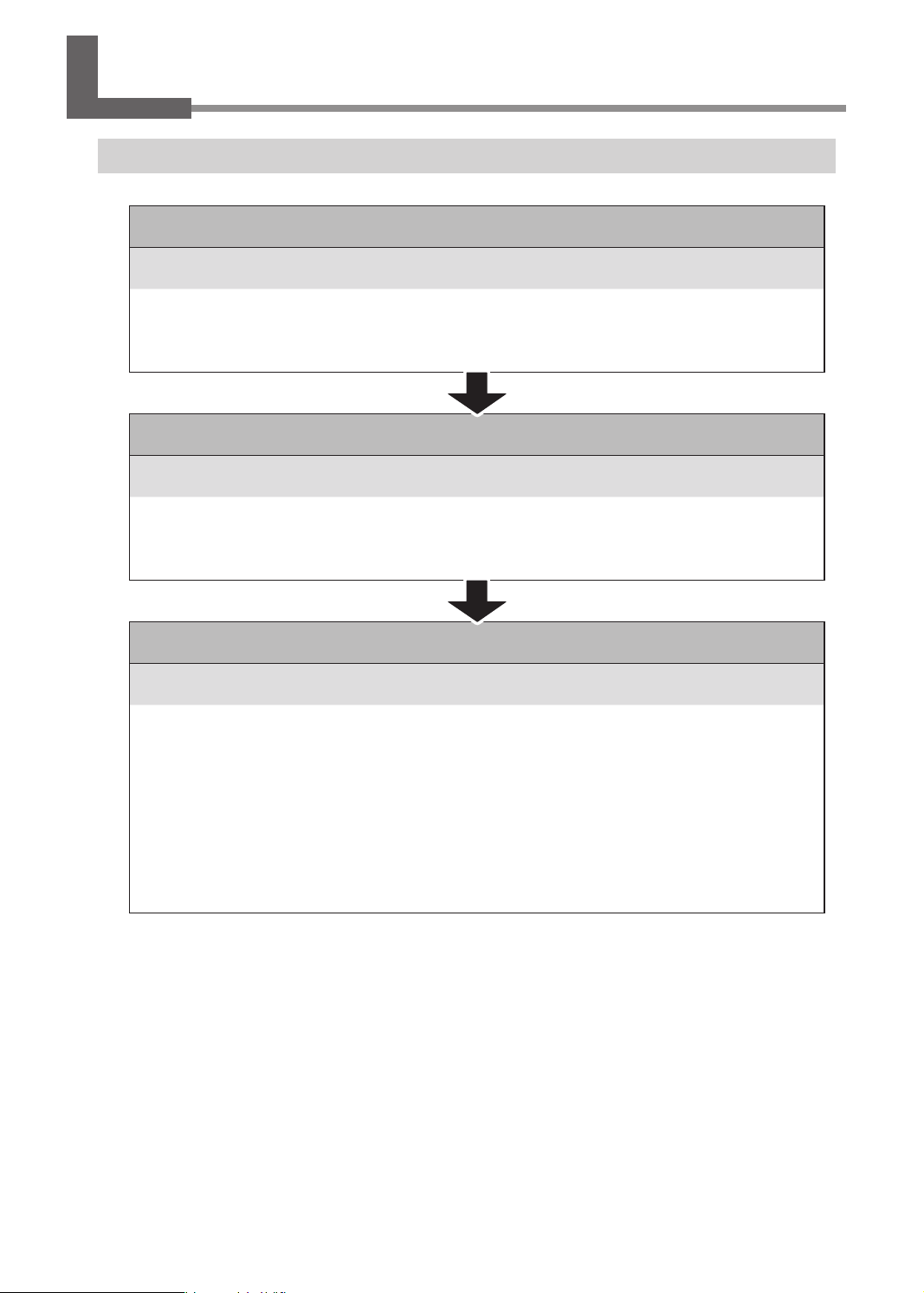
Checking the Flow of Engraving Operation
P. 25 "Checks and Preparation before Engraving"
Check the conditions, material and tool required to start engraving.
P. 26 "Checking Engravable Workpieces"
P. 27 "Determining the Item to Create and Required Material and Tool"
P. 28 "Creating Engraving Data"
Create engraving data using Dr. Engrave Plus.
Determine the design and draw
P. 35 "Setting the Engraving Parameters"
P. 38 "Starting Engraving"
Set the workpiece and tool, and send the engraving data to this machine.
P. 38 "Step 1: Setting the Workpiece"
P. 39 "Step 2: Setting the XY Origin"
P. 41 "Step 3: Installing a Character Cutter/Parallel Cutter"
P. 51 "Step 4: Checking the Engraving Parameters"
P. 54 "Step 5: Starting Engraving"
Chapter 3 Basic Engraving Methods
25
Page 28
Checks and Preparation before Engraving
Checking Engravable Workpieces
Material
• Acrylic
• Modeling wax
• Aluminum
• Brass
• Wood
• Chemical wood
etc.
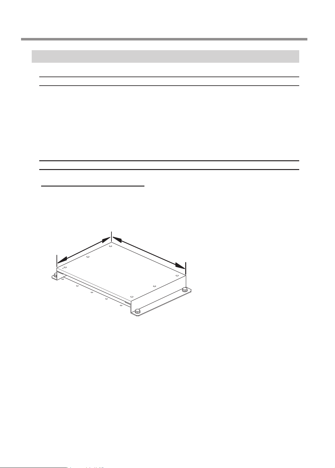
Size
Size that can be stably xed in place.
On this machine, an adhesive sheet is used to x the workpiece in place. The workpiece can be large and can stick
out of the workpiece table, but you must be able to stably x it in place.
* XY operating range (workpiece table size): Width × Depth: 305 × 230 mm (12.0 × 9.1 in.)
230 mm (9.1 in.)
305 mm (12.0 in.)
26
Chapter 3 Basic Engraving Methods
Page 29
Checks and Preparation before Engraving
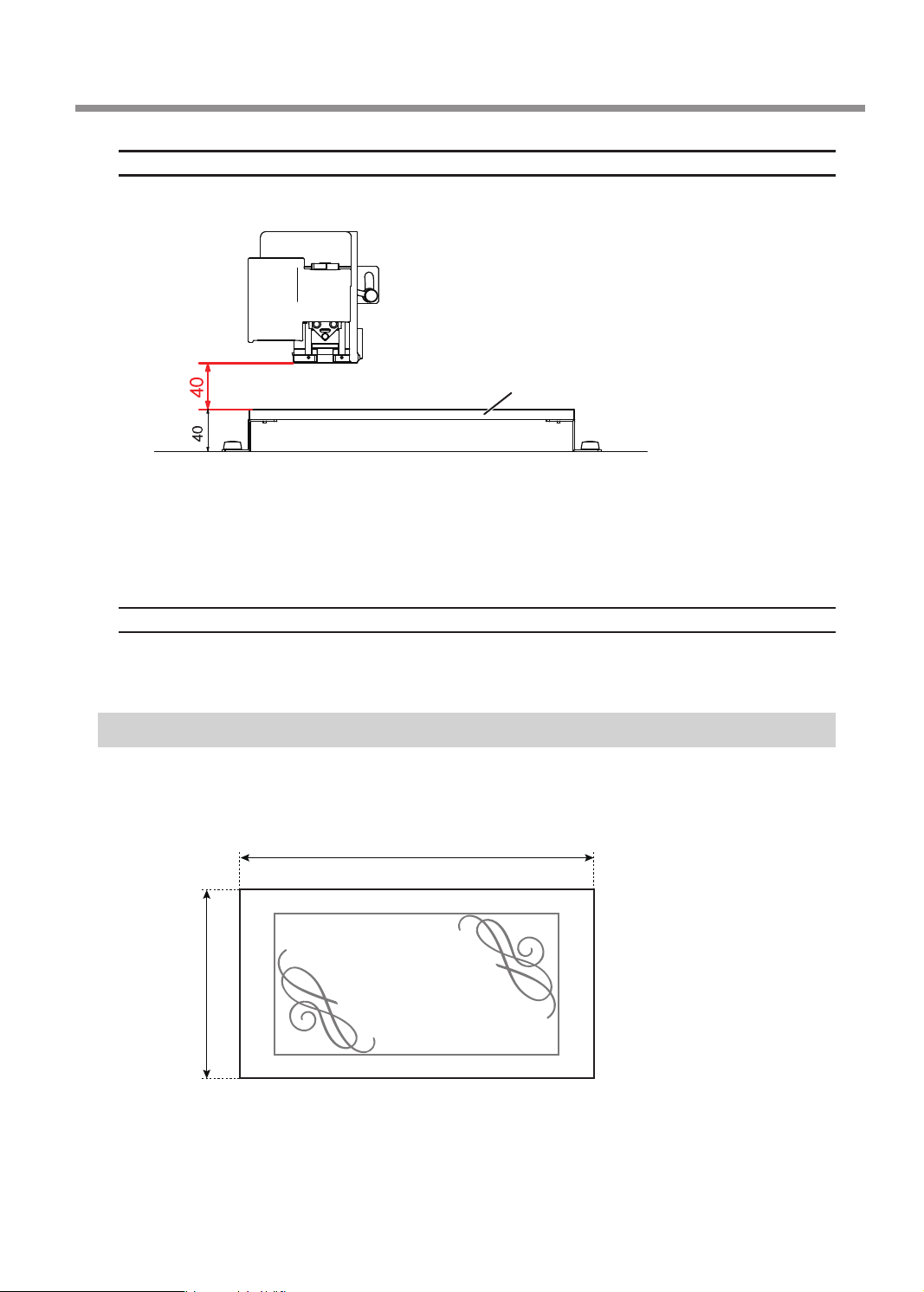
Thickness
The thickness must be 40 mm (1.6 in.) or less whereby the height for the tool to avoid the workpiece can be
maintained during engraving.
Thickness of attachable workpieces = 40 mm
(1.6 in.)
* The thickness of workpiece that can actually be engraved is restricted by the length of the installed tool,
the location where the nose unit is installed and the cut-out amount, and is smaller than the range
indicated above.
* When nose unit is used: The maximum distance between the workpiece table and the tip of the nose unit
is 38 mm (1.5 in.).
Workpiece table
Shape
The surface to be engraved is level.
* When nose unit is used: Gentle undulations of less than 1 mm (0.04 in.) (trackable undulation height).
Determining the Item to Create and Required Material and Tool
In this example, you will create a celebration gift using the following material and tool.
¾ Material (workpiece): Wood
¾ Tool: Character cutter ø3.175 (ZEC-A2025)
75 mm (3.0 in.)
40 mm
(1.6 in.)
Congraturations
Chapter 3 Basic Engraving Methods
27
Page 30

Creating Engraving Data
Step 1: Starting Dr. Engrave Plus
Procedure
Windows 10
Click the [Start] button.
A
Click the [Dr. Engrave Plus] icon under [DGSHAPE Dr. Engrave Plus].
B
Windows 8.1
Click the [Start] screen.
A
On the [Apps] screen, click [Dr. Engrave Plus].
B
Windows 7
Click the [Start] button.
A
Click the [All Programs] (or [Programs]).
B
Click the [Dr. Engrave Plus] icon under [DGSHAPE Dr. Engrave Plus].
C
28
Chapter 3 Basic Engraving Methods
Page 31

Dr. Engrave Plus Screen
1
2
3
Creating Engraving Data
4
No. Name Functional overview
1
2
3
4
Menu Bar
Standard tool bar
Shape tool bar
Docking panel
(operation panel)
This runs the various functions for Dr. Engrave Plus.
Displays frequently used functions among the functions on the menu bar.
Displays functions related to drawing and editing of shapes.
This is used to congure mainly shape settings. You can integrate this
into the main screen or separate it. You can also combine panels to
create tabbed panels.
Chapter 3 Basic Engraving Methods
29
Page 32

Creating Engraving Data
Step 2: Creating a Shape
Draw a rectangle.
30 mm
(1.2 in.)
5 mm
(0.2 in.)
Procedure
Click .
A
7 mm
(0.3 in.)
Congraturations
60 mm (2.4 in.)
30
Click the start point at any location, and then drag it to the end point.
B
Start point
End point
Chapter 3 Basic Engraving Methods
Page 33

Enter the [Size] and [Position] in the [Shape] panel.
C
Enter the following values.
5 mm
(0.2 in.)
Creating Engraving Data
Size
30 mm
(1.2 in.)
60 mm (2.4 in.)
Position
Reference point
(lower-left corner of the shape)
7 mm (0.3 in.)
You can change or move the shape you drew to any size and position.
Step 3: Loading an Image
You can load the image you have prepared in advance, extract its contour and convert it into a line segment. For
example, you can import logo data of a company or an organization, or illustration data for engraving. As an
example, the procedure for loading an Adobe Illustrator le is explained in this section.
Data Formats That Can Be Imported (Extension)
• Adobe Illustrator version 7/8 les (ai/eps format)
* There are multiple limitations on Adobe Illustrator les. For details, see the Dr. Engrave Plus help.
" Dr. Engrave Plus help ("Creating Objects" - "Importing an Existing Image File")
• Other image les (bmp/jpg/png format)
Select the image le.
1.
Click [Import].
A
The [Import] window is displayed.
Chapter 3 Basic Engraving Methods
31
Page 34

Creating Engraving Data
From [File Type], select "Adobe Illustrator Files."
B
Open [the drive on which Dr. Engrave Plus is installed]* - [ProgramData] - [DGSHAPE
C
Corporation] - [Dr. Engrave Plus] - [Sample] and select "Gift_DE3.ai."
* This is most commonly the [C drive] or [D drive].
Click [Open].
D
The selected image is placed on the screen.
32
Position an image le.
2.
Click .
A
Click the image you have imported.
B
■ appears on the four corners of the image.
Chapter 3 Basic Engraving Methods
Page 35

Creating Engraving Data
Drag ■ to adjust the size.
C
To enlarge/reduce the size with the aspect ratio xed, hold down the [Shift] key as you drag it.
Drag the image to move it to the target position.
D
Step 4: Entering Text
Enter text and determine its font, etc.
1.
Click .
A
Click any position on the screen.
B
You will change the position later on. At this point, click a position you want.
Enter text, such as name, using the keyboard.
C
Chapter 3 Basic Engraving Methods
33
Page 36

Creating Engraving Data
Click .
D
Click the text that you entered.
E
■ appears on the four corners of the image.
Set the font, text size, etc. on the [Text] panel.
F
Enter as follows:
Position the text.
2.
Using the mouse, drag the text to move it to the target position.
34
Chapter 3 Basic Engraving Methods
Page 37

MEMO
You can set the text's position and slant in the [Shape] panel.
Step 5: Setting the Engraving Parameters
Set parameters such as the material to engrave, the tool, and the depth.
Creating Engraving Data
Procedure
Click the shape you are going to engrave.
A
Double-click the layer on which the shape to engrave is drawn on the [Layer] panel.
B
Click [Engraving Parameters].
C
Because the automatic Z control feature is used, there is no need to set the [Depth].
" P. 42 "1. Make the settings for Z-axis control."
Chapter 3 Basic Engraving Methods
35
Page 38

Creating Engraving Data
Select the [Material] and [Tool].
D
• Material: Wood (Hard)
• Tool: ZEC-A2025
MEMO
The engraving parameters are set automatically according to the selected [Material] and [Tool].
To change the engraving parameters, click [Advanced Settings] and change the settings.
" P. 96 "Detailed Settings on the [Engraving Parameters] Screen"
36
Click [OK].
E
The [Engraving Parameters] screen closes.
Click [OK].
F
Chapter 3 Basic Engraving Methods
Page 39

Step 6: Saving Engraving Data
Procedure
Click [Save].
A
Specify where to save the le.
B
Enter the le name.
C
Click [Save].
D
B
Creating Engraving Data
C
A le with the extension *.dpd is saved.
D
Chapter 3 Basic Engraving Methods
37
Page 40

Starting Engraving
WARNING
Keep open ame away from the work area.
Cutting waste may ignite. Powdered material is extremely ammable, and even
metal material may catch re.
Step 1: Setting the Workpiece
WARNING
Procedure
Set the adhesive sheet.
A
Afx the adhesive sheet to the workpiece table.
Set the workpiece.
B
Place the workpiece on the adhesive sheet and press down on it from above.
Never inadvertently touch the computer or handy panel while performing this
task.
Unintended operation of the machine may lead to you being caught in the
machine.
Adhesive sheet
A
MEMO
On this machine, you can use the optional center vise and T-slot table to secure the workpiece in place. For details
on these optional items, contact your authorized DGSHAPE Corporation dealer or access our website (http://www.
dgshape.com/).
38
Chapter 3 Basic Engraving Methods
Workpiece
B
Workpiece table
Page 41

Starting Engraving
Step 2: Setting the XY Origin
Set the X- and Y-axis coordinates, which will be the origin point of engraving. This position is called the "XY origin."
On this machine, you can set the XY origin in any position within the operating range. Set this to match the
engraving data and workpiece mounting position.
Procedure
Close the front cover.
A
Press [ENTER/PAUSE].
B
When the initial operation is complete, the main screen appears.
Hold down and press [ORG.XY/POINTER].
C
The laser pointer turns on.
Press [ ], [ ], [ ], and [ ] to move the laser pointer to the position you want to set as the
D
XY origin.
" P. 19 "Moving to the Desired Position"
Origin
Press [ORG.XY/POINTER].
E
Chapter 3 Basic Engraving Methods
39
Page 42

Starting Engraving
Using the [Dial], select [XY] for the target axis.
F
012345678901234567 READY
ORIGIN SET XY
XY X Y
X 38.88mm
Y 17.00mm
MEMO
You can set the origins of the X and Y axes separately by selecting [X] or [Y] for the target axis.
Press [ENTER/PAUSE].
G
The current value is set as the origin point, and you are returned to the main screen.
012345678901234567 READY
X 0.00mm
Y 0.00mm
Z 39.00mm S 5000rpm
Target axis
The machine coordinate is displayed.
Hold down and press [ORG.XY/POINTER].
H
The laser pointer turns off.
40
Chapter 3 Basic Engraving Methods
Page 43

Step 3: Installing a Character Cutter/Parallel Cutter
Use the nose unit when engraving using a character cutter or parallel cutter.
" P. 83 "Nose Unit Overview and Precautions"
WARNING
WARNING
CAUTION
CAUTION
Never inadvertently touch the computer or handy panel while performing this task.
Unintended operation of the machine may lead to you being caught in the machine.
Securely fasten the cutting tool and workpiece in place. After securing in place,
make sure no spanners or other articles have been left behind inadvertently.
Otherwise, such articles may be thrown from the machine with force, posing a
risk of injury.
Be careful around the cutting tool.
The cutting tool is sharp. Broken cutting tools are also dangerous. To avoid injury,
exercise caution.
The machine contains blades and other sharp components.
Be careful not to touch the tool tip or any other sharp edges. Doing so may cause
injury.
Items used in this procedure
Starting Engraving
Character cutter
or
parallel cutter
Nose cone
(resin or metal)
*1 There are two types of solid collets. Use a solid collet that ts the diameter of the cutter that will be used. Collet
for ø4.36 cutters is an optional item.
*2 Use a resin or metal nose cone. To use it selectively, refer to P. 44 “Assemble the nose unit.” in the procedure.
Automatic Z control ON
Spindle rotation ON
Lock lever position
Solid collet
Nose unit
*1
*2
Settings for this machine
or
Hexagonal
screwdriver
Spring
Retaining screw
Wrenches (2)
Vacuum adapter
Chapter 3 Basic Engraving Methods
41
Page 44

Starting Engraving
Make the settings for Z-axis control.
1.
If the front cover is open, close it.
A
Press [ENTER/PAUSE].
B
When the initial operation is complete, the main screen appears.
Press [MENU] several times to display the following screen.
C
012345678901234567 READY
SETTINGS
OPERATING MODE
SPINDLE REVOLUTION ON
AUTO Z CONTROL OFF
Turn the [Dial] and select [AUTO Z CONTROL].
D
Press [ENTER/PAUSE].
E
Turn the [Dial] and select [ON].
F
The machine automatically sets the Z-axis origin during engraving according to the height of the
workpiece.
* The [Depth] setting selected in the software is disabled.
012345678901234567 READY
SETTINGS
OPERATING MODE
SPINDLE REVOLUTION ON
AUTO Z CONTROL ON
Press [ENTER/PAUSE] to conrm.
G
After the following message is displayed for three seconds, the previous screen appears again.
012345678901234567 READY
Please set the lock lever
at the 1 or 2 position.
Important: Accurately perform P. 45 "3. Set the lock lever." later in this procedure.
Press [MENU/TOP].
H
The main screen appears again. The Z-axis coordinate display changes to [AUTO].
012345678901234567 READY
X 15.00mm
Y 39.00mm
Z AUTO S 5000rpm
42
Chapter 3 Basic Engraving Methods
Page 45

Starting Engraving
Install the cutter holder, solid collet, and nose unit.
2.
Open the front cover.
A
Detach the cutter holder from the cutter.
B
Hexagonal screwdriver
Loosen
Cutter holder
Install the cutter holder on the spindle unit.
C
While holding the spindle unit immobile with a wrench, tighten the cutter holder.
The cutter holder is reverse-threaded (that is, you turn it counterclockwise to tighten it). Be careful to
turn it in the correct direction.
Turn counterclockwise
Wrench
Spindle unit
Attach a solid collet that ts the diameter of the cutter.
D
There are two types of solid collets. Use a solid collet that ts the diameter of the cutter.
For ø3.175 mm (0.125 in.)
For ø4.36 mm (0.17 in.)
(Optional item)
Cutter holder
Chapter 3 Basic Engraving Methods
43
Page 46

Starting Engraving
1 Temporarily tighten the solid collet.
Insert the solid collet into the spindle unit from below while holding the spindle unit immobile with a
wrench, and tighten temporarily.
Wrench
2 Fully tighten the solid collet.
Using two wrenches, fully tighten the solid collet.
Spindle unit
Solid collet
Wrench
Wrench
Assemble the nose unit.
E
There is a resin nose cone and a metal one. Select one and assemble.
¾ Resin nose cone: Use this when engraving a workpiece made from material that easily scratches.
¾ Metal nose cone: Use this when engraving a workpiece made from material that hardly scratches.
Nose cone
2 Tighten1 Place
44
Chapter 3 Basic Engraving Methods
Page 47

Attach the nose unit to this machine.
F
Tighten until it does not move, and then loosen about two rotations and set the scale to "0."
Turn here
Loosen
Tighten
Set the lock lever.
3.
Set the lock lever at or position.
For details on the setting position of the lock lever, see P. 62 "Setting the Lock Lever".
Starting Engraving
Lock lever
Press slightly, then lower it.
Install the cutter and set the engraving depth.
4.
Close the front cover.
A
Press [ENTER/PAUSE].
B
When the initial operation is complete, the main screen appears.
Chapter 3 Basic Engraving Methods
45
Page 48

Starting Engraving
Press [ ], [ ], [ ], and [ ] to move the spindle head to the area above the workpiece.
C
Press [-Z] to lower the spindle head.
D
When the tip of the nose unit touches the workpiece, descent automatically stops.
Workpiece
Open the front cover.
E
Insert the cutter into the cutter holder and bring the tip of the cutter into contact with the
F
workpiece.
Cutter
Cutter holder
Workpiece
46
Chapter 3 Basic Engraving Methods
Page 49

Starting Engraving
Point: If cutter insertion is difcult
If the cutter catches on the solid collet and is dicult to insert, loosening the cutter holder makes insertion easier.
Note that inserting it forcibly may result in damage to the workpiece. After inserting the cutter, tighten the cutter
holder again.
Loosen the cutter holder
MEMO: When using a ø4.36 mm (0.17 in.) solid collet
Be careful to orient the cutter correctly. If insertion is dicult, try turning the cutter until it is smoothly inserted.
Good Not Good
Secure the cutter in place.
G
Tighten the mounting screw for the cutter holder.
Cutter holder
Hexagonal screwdriver
Cutter
Solid collet
Protrusion
Protrusion
Mounting screw
Chapter 3 Basic Engraving Methods
47
Page 50

Starting Engraving
Set the engraving depth.
H
Adjust the amount of extension of the cutter after raising the cutter to prevent the workpiece from being scratched.
1 Close the front cover and press [ENTER/PAUSE].
2 Press [ +Z] to move the cutter to the upper limit of the z-axis.
3 Open the front cover.
4 Turn the scale of the nose unit to match the desired engraving depth.
The amount of extension of the cutter is the engraving depth.
* The [Depth] setting selected in the software is disabled.
1 full turn =
0.635 mm (0.025 in.)
4 scale ticks =
Approx. 0.1 mm (0.004 in.)
1 scale tick
= 0.0254 mm
(0.001 in.)
5 Secure the nose unit with a retaining screw.
Retaining
screw
Retaining
screw
Spring
Close the front cover.
I
Press [ENTER/PAUSE].
J
Attach the vacuum adapter.
5.
For precautions regarding attaching the vacuum adapter, see P. 58 "Attaching the Vacuum Adapter".
Nose unit
48
Turn off this machine.
A
Open the front cover.
B
Chapter 3 Basic Engraving Methods
Page 51

Starting Engraving
Slowly move the spindle head by hand to the back of the workpiece table on the right side.
C
Be careful not to apply strong impact.
Top
Pass the end of the dust collection hose ("hose") from the front to the back of this
D
machine.
Back
Hose
Fasten the hose with the clamp close to the back of this machine.
E
Fasten at the position of the retaining band on the hose.
Front
Clamp
Workpiece table
Hose
MEMO
Opening the clamp Closing the clamp
Fasten at the
position where
you hear a
"click."
Chapter 3 Basic Engraving Methods
49
Page 52

Starting Engraving
Slowly move the spindle head by hand to the front left.
F
Be careful not to apply strong impact.
Fasten the hose with the (two) clamps in the center of this machine.
G
Top
Clamp Clamp
Retaining band
Attach the vacuum adapter to the nose unit.
H
Secure the vacuum adapter while pressing it against the top.
Point 1: Attach it so that it is level.
Good Not Good
Screw
1 Attach from below
2 Tighten the screw
Point 2: Tighten so that the notch is on the front.
Notch
Failing to do so may lead to the
hose bending during operation,
disabling the suction of the cutting
waste.
50
Chapter 3 Basic Engraving Methods
Page 53

Attach the adapter to the hose on the back of this machine.
I
Hose
Adapter
Attach a vacuum cleaner to the end of the adapter on the back.
J
Close the front cover.
K
Press [ENTER/PAUSE].
L
" P. 58 "Before using the vacuum adapter, be sure to verify the following points"
Step 4: Checking the Engraving Parameters
Starting Engraving
Start Dr. Engrave Plus.
A
If engraving data is already opened, proceed to step E.
Click [Open].
B
Select the data to engrave.
C
Click [Open].
D
C
D
Chapter 3 Basic Engraving Methods
51
Page 54

Starting Engraving
Click the shape you want to check the engraving parameters for.
E
Double-click the layer on which the shape to engrave is drawn on the [Layer] panel.
F
Check the engraving parameters.
G
1 Click [Engraving Parameters].
* Because the automatic Z control feature is used, there is no need to set the [Depth].
52
2 Check the [Material] and [Tool] that have been set.
Chapter 3 Basic Engraving Methods
Page 55

3 Click [Advanced Settings] and check the settings.
Set the items as required.
" P. 96 "Detailed Settings on the [Engraving Parameters] Screen"
4 Click [OK].
Starting Engraving
The [Engraving Parameters] screen closes.
5 Click [OK].
Open the front cover.
H
Chapter 3 Basic Engraving Methods
53
Page 56

Starting Engraving
Check the scale of the nose unit.
I
Conrm that the scale of the nose unit is set to the desired engraving depth. The amount of extension
of the cutter is the engraving depth.
1 full turn =
0.635 mm (0.025 in.)
If you have changed the settings, save the engraving data.
" P. 37 "Step 6: Saving Engraving Data"
4 scale ticks =
Approx. 0.1 mm (0.004 in.)
1 scale tick
= 0.0254 mm
(0.001 in.)
Step 5: Starting Engraving
Make sure the following tasks have all been completed, then sent the engraving data from the computer.
• Mounting the workpiece
" P. 38 "Step 1: Setting the Workpiece"
• Setting the XY origin
" P. 39 "Step 2: Setting the XY Origin"
• Installing a tool
" P. 41 "Step 3: Installing a Character Cutter/Parallel Cutter"
" P. 88 "Using a Diamond Scraper"
" P. 97 "Using an End Mill"
CAUTION
This procedure makes this machine operate.
Before you perform this procedure, check to make sure that operation of this
machine will not create any hazard or danger.
Procedure
If the front cover is open, close it, and then press [ENTER/PAUSE].
A
Press [MENU/TOP] several times to display the main screen.
B
012345678901234567 READY
X 50.00mm
Y 30.00mm
Z 20.00mm S 5000rpm
54
Chapter 3 Basic Engraving Methods
Page 57

Click [Engrave].
C
The [Engrave] screen appears.
Select [DGSHAPE DE-3] for the [Printer Name].
D
Click [OK].
E
E
Starting Engraving
F
The engraving data is sent to the machine.
When the following screen is displayed on the panel of this machine, select [Start].
F
012345678901234567 PAUSE
Data received.
Start CancelJob
Press [ENTER/PAUSE].
G
Engraving starts.
Important: When connected to multiple machines with LAN cables
Output data from the computer to one machine at a time. Simultaneous output to multiple machines is not
supported. After the data output to one machine is nished, output data to the next machine.
Important: Do not open the front cover during operation.
Opening the front cover during engraving or while the spindle is rotating may aect the engraving quality. If you
want to open the front cover during operation, press [ENTER/PAUSE] to pause the operations, wait for the
operations to stop, and then open the front cover.
" P. 21 "Pausing and Resuming Engraving"
Chapter 3 Basic Engraving Methods
55
Page 58

OVERRIDE
Other Basic Operations
Adjusting the Tool Feeding Speed and the Number of Rotations
during Engraving (Override)
You adjust the engraving parameters by specifying the ratio of change relative to the present feeding speed and
spindle rotating speed. This feature is called "override."
An override is possible only within the range of this machine's settable feeding speed and spindle rotating speed.
If a feeding speed that falls outside the settable range is set by an override, the actual feeding speed is limited to
the maximum or minimum value.
Procedure
While engraving is in progress, press [ENTER/PAUSE].
A
Engraving pauses.
" P. 21 "Pausing and Resuming Engraving"
012345678901234567 PAUSE
X 15.00mm
Y 23.00mm
XYZ 100%
S 100%
Z 0.00mm S 5000rpm
Set the ratios of change.
B
1 Press [MENU/TOP] twice to display the following screen.
0123456789012345678 BUSY
S 100%
XYZ 100%
2 Select the targets for the setting using the [Dial].
S : Set the change ratio of spindle rotating speed.
XYZ : Set the change ratios of the feeding speed of the tool for X, Y, and Z axes.
56
Chapter 3 Basic Engraving Methods
Page 59

3 Press [ENTER/PAUSE].
4 Select the change ratios using the [Dial].
5 Press [ENTER/PAUSE] to conrm.
Press [MENU/TOP].
C
The main screen in the paused state appears again.
012345678901234567 PAUSE
X 15.00mm
Y 23.00mm
XYZ 100%
S 100%
Z 0.00mm S 5000rpm
Other Basic Operations
Press [ENTER/PAUSE].
D
012345678901234567 PAUSE
Resume cutting?
Yes No CancelJob
Select [Yes] using the [Dial].
E
Press [ENTER/PAUSE].
F
Engraving resumes.
Settable Change Ratios
10 to 200% (in steps of 1%)
Chapter 3 Basic Engraving Methods
57
Page 60

Other Basic Operations
Attaching the Vacuum Adapter
This lets you perform engraving while taking up cutting waste using a vacuum cleaner with the vacuum adapter
attached. This can minimize scattering of cutting waste.
WARNING
CAUTION
CAUTION
When using a vacuum cleaner to take up cutting waste, exercise caution to
prevent re or dust explosion.
Picking up ne cuttings using an ordinary vacuum cleaner may result in re or
explosion. Check with the manufacturer of the vacuum cleaner. When the safety
of use cannot be determined, clean the machine using a brush or the like, without
using a vacuum cleaner.
The machine contains blades and other sharp components.
Be careful not to touch the tool tip or any other sharp edges. Doing so may cause
injury.
Do not touch the spindle unit immediately after engraving has ended.
Doing so may result in burns.
Before using the vacuum adapter, be sure to verify the following points
• Use a vacuum cleaner that allows adjustment of the suction force and is equipped with an
overload protector.
To prevent re or explosion, carefully check the specications of your vacuum cleaner before use, including
contacting the manufacturer if necessary.
• Be sure to use the nose unit.
The vacuum adapter cannot be attached unless the nose unit is installed.
" P. 43 "2. Install the cutter holder, solid collet, and nose unit."
• Be sure to use a vacuum cleaner hose having a diameter that allows connection with the
vacuum adapter hose.
The diameter of the vacuum adapter hose is 32 mm (1.3 in.).
32 mm (1.3 in.)
Avoid touching the rails while performing work
Needlessly touching the rails will remove their grease, leading to the rails rusting.
Rail
58
Chapter 3 Basic Engraving Methods
Page 61

Other Basic Operations
Procedure
Turn off this machine.
A
Open the front cover.
B
Slowly move the spindle head by hand to the back of the workpiece table on the right side.
C
Be careful not to apply strong impact.
Top
Pass the end of the dust collection hose ("hose") from the front to the back of this
D
machine.
Back
Hose
Chapter 3 Basic Engraving Methods
59
Page 62

Other Basic Operations
Fasten the hose with the clamp close to the back of this machine.
E
Fasten at the position of the retaining band on the hose.
Front
Clamp
MEMO
Opening the clamp
Slowly move the spindle head by hand to the front left.
F
Be careful not to apply strong impact.
Workpiece table
Hose
Closing the clamp
Fasten at the
position where
you hear a
"click."
Top
Fasten the hose with the (two) clamps in the center of this machine.
G
Clamp Clamp
Retaining band
60
Chapter 3 Basic Engraving Methods
Page 63

Attach the vacuum adapter to the nose unit.
H
Secure the vacuum adapter while pressing it against the top.
Point 1: Attach it so that it is level.
Good Not Good
Other Basic Operations
Screw
1 Attach from below
Point 2: Tighten so that the notch is on the front.
Notch
2 Tighten the screw
Attach the adapter to the hose on the back of this machine.
I
Hose
Adapter
Attach a vacuum cleaner to the end of the adapter on the back.
J
Close the front cover.
K
Failing to do so may lead to the
hose bending during operation,
disabling the suction of the cutting
waste.
Chapter 3 Basic Engraving Methods
61
Page 64

Other Basic Operations
Setting the Lock Lever
You change the position at which the lock lever is set to match the setting for automatic Z control.
•
or
When [AUTO Z CONTROL] is set to [ON], you set the lock lever at one of these positions. The spindle head is
put into a oating state, and the Z-axis origin point is determined by the height of the workpiece surface.
The
setting applies greater pressure to the workpiece than .
•
When [AUTO Z CONTROL] is set to [OFF], you set the lock lever at this position. The spindle head is locked,
and so the setting for the Z-axis origin point must be made via the menu items. Setting the lock lever at this
position when [AUTO Z CONTROL] is set to [ON] causes errors when setting the origin point or engraving,
resulting in an emergency stop of this machine.
" P. 144 "Responding to an Error Message"
Lock lever
To raise: Simply lift up the lever.
○
To lower: Press the lever in slightly, then lower it.
○
62
Chapter 3 Basic Engraving Methods
Page 65

Changing the Operation Mode
This selects the operation when engraving data is sent from the computer.
Procedure
If the front cover is open, close it.
A
Press [ENTER/PAUSE].
B
Press [MENU] several times to display the following screen.
C
012345678901234567 READY
SETTINGS
OPERATING MODE
SPINDLE REVOLUTION ON
AUTO Z CONTROL OFF
Press [ENTER/PAUSE].
D
Turn the [Dial] and select the operation.
E
012345678901234567 READY
OPERATING MODE
CUT
PREVIEW PATH
PREVIEW AREA
Other Basic Operations
CUT : The engraving starts.
PREVIEW PATH
PREVIEW AREA
Press [ENTER/PAUSE] to conrm.
F
The main screen appears again.
012345678901234567 READY
:
The laser pointer traces the path of the tool during engraving.
The laser pointer pauses at the four corners of the engraving area to indicate the area.
:
X 15.00mm
Y 23.00mm
Z 0.00mm S 5000rpm
Important
If the operating mode is set to [PREVIEW PATH] or [PREVIEW AREA], this setting returns to [CUT] after engraving
data is output once. If you want to perform a preview when outputting the engraving data the second time as
well, set the operating mode again prior to output or select [Engraving Preview] from the menu in Dr. Engrave
Plus.
" P. 118 "Previewing before Engraving"
Chapter 3 Basic Engraving Methods
63
Page 66

SETTING
Other Basic Operations
Setting the Avoidance Height of the Tool to Match the Workpiece Shape
When moving to another engraving area, the tool rst avoids the workpiece in the upward direction, and then
moves along the X and Y axes. Make the setting for this avoidance height.
* This setting is enabled when [AUTO Z CONTROL] is set to [ON].
* With the engraving data created using Dr. Engrave Plus, the setting for the [Tool-up Height] within the
software is ignored.
" P. 96 "Detailed Settings on the [Engraving Parameters] Screen"
The avoidance
Z user origin
Procedure
height you have set
Surface to be engraved
If the front cover is open, close it.
A
Press [ENTER/PAUSE].
B
Press [MENU] several times to display the following screen.
C
012345678901234567 READY
SETTINGS
OPERATING MODE
SPINDLE REVOLUTION ON
AUTO Z CONTROL ON
Turn the [Dial] and select [AUTO Z SETTING].
D
012345678901234567 READY
OVER AREA CONTINUE
START MESSAGE ON
AUTO Z SETTING
Press [ENTER/PAUSE] twice.
E
64
Chapter 3 Basic Engraving Methods
Page 67

Turn the [Dial] and set the avoidance height.
AUTO Z SETTING
F
For the setting value, set the distance from Z user origin.
If the dierence in level is above the origin, specify the setting value
that exceeds the dierence in level.
012345678901234567 READY
Other Basic Operations
UP 5.00mm
Press [ENTER/PAUSE] to conrm.
G
Hold down and press [MENU/TOP].
H
The main screen appears again.
012345678901234567 READY
The avoidance
height you have set
X 15.00mm
Y 23.00mm
Z 0.00mm S 5000rpm
Setting Range
0 mm to 40 mm (1.6 in.) (in 0.1 mm [3.9 mil] steps)
Z user origin
Workpiece
Chapter 3 Basic Engraving Methods
65
Page 68

Chapter 4 Maintenance
Maintenance Precautions .............................................................................................................. 67
Daily Care ............................................................................................................................................ 68
Cleaning after Engraving Finishes ..................................................................................68
Cleaning Inside the Spindle Unit Cover ....................................................................... 69
Storing the Cutter .................................................................................................................70
Replacing Consumable Parts ....................................................................................................... 71
Replacing the Spindle Unit ............................................................................................... 71
Replacing the Resin Nose Cone ...................................................................................... 73
Correction ........................................................................................................................................... 75
Distance Correction ............................................................................................................. 75
Laser Correction .................................................................................................................... 75
When Moving the Machine .......................................................................................................... 78
When the Machine Has Not Been Used for a Prolonged Period .....................................80
Spindle Run-in (Warm-up) ................................................................................................ 80
66
Chapter 4 Maintenance
Page 69

Maintenance Precautions
WARNING
WARNING
WARNING
WARNING
WARNING
CAUTION
CAUTION
• Carefully clean away cutting waste. Operating the machine with a large amount of cutting waste present
may cause malfunctions.
• Never apply lubrication.
• Never apply silicone substances (oil, grease, spray, etc.) to the machine. Doing so may cause poor switch
contact.
Perform this task with all power switches left switched off.
Otherwise sudden movement of the machine may cause injury.
Never use a pneumatic blower.
This machine is not compatible with a pneumatic blower. Cutting waste may get
inside the machine and cause re or electrical shock.
Never use a solvent such as gasoline, alcohol, or thinner to perform cleaning.
Doing so may cause a re.
When using a vacuum cleaner to take up cutting waste, exercise caution to
prevent re or dust explosion.
Picking up ne cuttings using an ordinary vacuum cleaner may result in re or
explosion. Check with the manufacturer of the vacuum cleaner. When the safety
of use cannot be determined, clean the machine using a brush or the like, without
using a vacuum cleaner.
Be sure to perform operations as specied by these instructions, and never
touch any area not specied in the instructions.
The machine may move in an unexpected way, resulting in injury or burns.
Do not touch the spindle unit immediately after engraving has ended.
Doing so may result in burns.
Remove the cutting tool before performing maintenance.
Contact with the blade may result in injury.
Chapter 4 Maintenance
67
Page 70
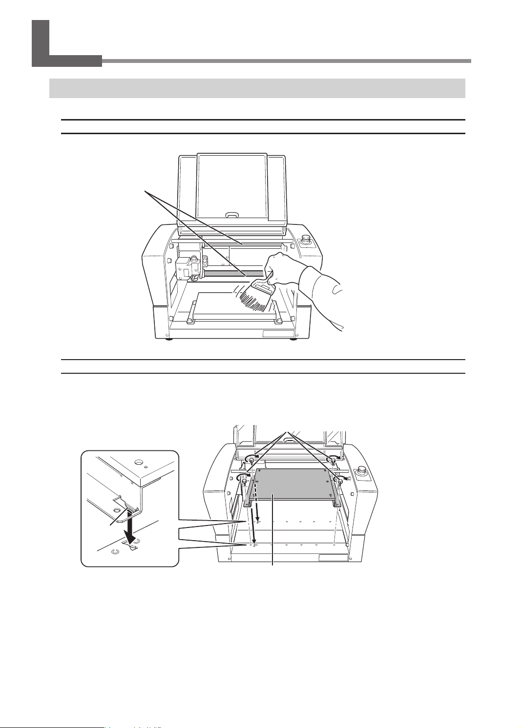
Daily Care
Cleaning after Engraving Finishes
Cleaning Inside the Front Cover
Open the front cover and clean away any buildup of cutting waste inside.
Never touch these rails.
Attaching the Workpiece Table
After removing the workpiece table and cleaning it, exercise caution regarding the positions of the tabs, orienting
them as shown in the gure when attaching the workpiece table. .
Insert the tabs of the workpiece table
into the grooves on this machine.
Tab
Retaining screws (for use with the standard table)
Workpiece table
68
Chapter 4 Maintenance
Page 71

Daily Care
Cleaning Near the Spindle Head
Uninstall the nose unit, collet, and tool, and remove any cutting waste that has collected in areas such as the tip of
the spindle unit and the laser pointer.
Spindle unit
Laser pointer
Cleaning Inside the Spindle Unit Cover
Detach the spindle unit cover and clean away any buildup of cutting waste inside.
Spindle unit cover
Screws (two locations)
Phillips head screwdriver
(commercially available)
Cap screw
Hexagonal
screwdriver
MEMO
Engraving while sucking up cutting waste using a vacuum cleaner by attaching the vacuum adapter can minimize
scattering of cutting waste only when the nose unit is used.
" P. 58 "Attaching the Vacuum Adapter"
* A dierent type of screw is used in one location.
Exercise caution when attaching the screws.
Spindle unit
Chapter 4 Maintenance
69
Page 72

Daily Care
Storing the Cutter
For repeated use while keeping the amount of extension of the cutter tip constant, we recommend that you
remove the cutter holder and cutter from the spindle unit without separating them from one another once you
have determined the amount of extension. Storing the assembly without changing the position of the cutter
holder eliminates the need to determine the amount of cutter extension each time you use it.
* This method cannot be used with the ø4.36 mm (0.17 in.) solid collet and end mill.
Storage Methods for ø3.175 mm (0.125 in.) Character Cutter/Parallel Cutter
Remove the cutter from the spindle unit together with the
cutter holder.
Store without changing the position of the
cutter holder.
Storage Method for the Diamond Scraper
Remove the entire diamond scraper from the spindle unit. Store without changing the position of the
cutter holder.
70
Chapter 4 Maintenance
Page 73

SETTINGS
INFORMATION
Replacing Consumable Parts
CAUTION
Remove the cutting tool before performing replacement work.
Contact with the blade may result in injury.
Replacing the Spindle Unit
The spindle unit and the belt are consumable parts. For information on how to perform replacement, refer to the
documentation included with the ZS-35S replacement spindle unit.
Checking the Replacement Time of the Spindle Unit
This machine is provided with a feature for displaying the total working time of the spindle unit. Refer to this to
determine when replacement is needed. The replacement cycle varies according to usage conditions, but as a
general guide, you should replace it after every 2,000 hours of use.
Procedure
Press [MENU/TOP] several times to display the following menu.
A
012345678901234567 READY
SETTINGS
OPERATING MODE
SPINDLE REVOLUTION ON
AUTO Z CONTROL OFF
Turn the [Dial] and select [INFORMATION].
B
012345678901234567 READY
LASER CORRECTION
LAN
INFORMATION
Press [ENTER/PAUSE].
C
Check the [SPINDLE UNIT] time.
D
The working time of the spindle motor is displayed.
012345678901234567 READY
SPINDLE UNIT 1999h50m
TOTAL WORK 2250h20m
Chapter 4 Maintenance
71
Page 74

SETTINGS
INFORMATION
Replacing Consumable Parts
Hold down and press [MENU/TOP].
E
The main screen appears again.
012345678901234567 READY
X 15.00mm
Y 23.00mm
Z 0.00mm S 5000rpm
Resetting the Working Time after Replacing the Spindle
After replacing the spindle, reset the working time.
Procedure
Press [MENU/TOP] several times to display the following menu.
A
012345678901234567 READY
SETTINGS
OPERATING MODE
SPINDLE REVOLUTION ON
AUTO Z CONTROL OFF
Turn the [Dial] and select [INFORMATION].
B
012345678901234567 READY
LASER CORRECTION
LAN
INFORMATION
Press [ENTER/PAUSE].
C
With [SPINDLE UNIT] selected, press [ENTER/PAUSE].
D
012345678901234567 READY
SPINDLE UNIT 1999h50m
TOTAL WORK 2250h20m
Select [Clear] using the [Dial].
E
012345678901234567 READY
SPINDLE UNIT
WORK TIME 1999h50m
OK Clear
72
Chapter 4 Maintenance
Page 75

Replacing Consumable Parts
Press [ENTER/PAUSE].
F
The working time of the spindle is reset.
Replacing the Resin Nose Cone
The resin nose cone is a consumable part. It wears out as you continue to perform engraving. Replace it at the
appropriate time.
Checking the Replacement Time
The resin nose cone should be replaced when it becomes worn to the protrusion as shown in the gure. Replace
the nose cone with a new one.
Protrusion
Replacement
Procedure
Loosen the retaining screw.
A
To prevent the retaining screw from being lost, just loosen the retaining screw enough to remove the
nose unit, leave the retaining screw attached.
Retaining screw
Nose unit
Chapter 4 Maintenance
73
Page 76

Replacing Consumable Parts
Remove the nose unit from this machine.
B
Turn here
Loosen and remove the ring.
C
Ring
Loosen
Replace the nose cone with a new one.
D
Nose cone
Tighten the ring.
E
Ring
74
Chapter 4 Maintenance
Page 77

DISTANCE CORRECTION
Correction
Distance Correction
Important
These settings aect the engraving accuracy. Set these values with great care. We do not recommend the
operation if you are not condent about the settings.
The distance correction for the X-axis and Y-axis can be set.
012345678901234567 READY
X 100.00%
Y 100.00%
Setting Range
99.5% to 100.5%
Laser Correction
If the previewed engraving position diers from the actual engraving position, correct the irradiation position of
the laser pointer.
Important
• Perform laser correction with the distance correction set to "100%."
When distance correction has been set to a value other than “100%," temporarily set the distance correction
to "100%" and perform laser correction. After laser correction nishes, return the distance correction to its
previously set value.
" P. 75 "Distance Correction"
Items Used in This Procedure
• Workpiece: Scrap board
• Tool: Character cutter
• Implements required for installing the tool
" P. 104 "Using a Character Cutter/Parallel Cutter (without Nose Unit)"
Mark the workpiece.
1.
Set the workpiece and tool.
A
" P. 38 "Step 1: Setting the Workpiece"
" P. 104 "Using a Character Cutter/Parallel Cutter (without Nose Unit)"
Chapter 4 Maintenance
75
Page 78

Correction
Close the front cover.
B
Press [ENTER/PAUSE].
C
The main screen is displayed.
Press [+Z] to raise the tool.
D
Press [ ], [ ], [ ], and [ ] to move the tool to a position on the workpiece.
E
Press [ORG.XY/POINTER].
F
Using the [Dial], select [XY] for the target axis.
G
Press [ENTER/PAUSE].
H
The current value is set as the origin point, and you are returned to the main screen.
012345678901234567 READY
ORIGIN SET XY
XY X Y
X 38.88mm
Y 17.00mm
Hold down [SPINDLE] for one second or longer.
I
The spindle rotates.
SPINDLE
ON/OFF
Press [-Z] to lower the tool until it cuts the workpiece.
J
The workpiece is marked.
Press [+Z] to raise the tool.
K
Press [SPINDLE].
L
Rotation of the spindle stops.
Examine the laser pointer correction values.
2.
Hold down and press [ORG.XY/POINTER].
A
The laser pointer turns on, and the current values of the laser pointer are displayed on the main screen.
76
012345678901234567 READY
X 50.00mm
Y 30.00mm
Z 20.00mm S 5000rpm
Chapter 4 Maintenance
Page 79

Press [ ], [ ], [ ], and [ ] to move the laser pointer to the position marked in step 1 - I.
SETTINGS
LASER CORRECTION
B
Write down the XY coordinates displayed on the main screen.
C
Set the correction values.
3.
Press [MENU/TOP] several times to display the following menu.
A
012345678901234567 READY
SETTINGS
OPERATING MODE
SPINDLE REVOLUTION ON
AUTO Z CONTROL OFF
Turn the [Dial] and select [LASER CORRECTION].
B
012345678901234567 READY
AUTO Z SETTING
DISTANCE CORRECTION
LASER CORRECTION
Correction
Press [ENTER/PAUSE].
C
The following window is displayed.
012345678901234567 READY
X 00.00mm
Y 00.00mm
Press [ENTER/PAUSE].
D
You can now change the settings.
Use the [Dial] to set the X value written down in step 2 - C.
E
Press [ENTER/PAUSE].
F
The X value is set.
Select [Y] using the [Dial].
G
Repeat steps D to F to set the Y value as well.
H
Setting Range
−3 mm to +3 mm (−0.1 in. to +0.1 in.)
Chapter 4 Maintenance
77
Page 80

When Moving the Machine
When moving the machine, attach the retainers to protect it from impact during movement.
Avoid touching the rails while performing work
Needlessly touching the rails will remove their grease, leading to the rails rusting.
Rail
Procedure
Make sure the machine is not in operation, then turn off the power switch.
A
The display screen on the handy panel goes dark.
Unplug all cables, such as power cord.
B
Remove retainers A, B, and C from the back of this machine.
C
Retainer A
Slowly move the spindle head to the back.
D
Retainers B and C
78
Chapter 4 Maintenance
Page 81

Attach retainers B and C.
E
When Moving the Machine
Retainer B
Slowly move the spindle head to the left.
F
Be careful not to apply strong impact.
Spindle head
Attach retainer A.
G
Hexagonal
wrench
Hexagonal
wrench
Retainer C
Hexagonal wrench
Retainer A
Chapter 4 Maintenance
79
Page 82

When the Machine Has Not Been Used for a Prolonged Period
Spindle Run-in (Warm-up)
Perform spindle run-in (warm-up) to stabilize the rotation of the spindle.
Procedure
Close the front cover.
A
Press [ENTER/PAUSE].
B
On the main screen, press [SPINDLE].
C
The cursor moves to [S], and the spindle rotating speed can be changed.
SPINDLE
ON/OFF
Turn the [Dial] on the handy panel until the spindle rotating speed reaches "5000 rpm."
D
012345678901234567 READY
X 50.00mm
Y 30.00mm
Z 20.00mm S 5000rpm
Slow
CAUTION
The spindle rotating speed can only be changed while the cursor is displayed at the [S] position.
012345678901234567 READY
Spindle rotating speed
Fast
X 50.00mm
Y 30.00mm
Z 20.00mm S 5000rpm
If no operations are performed for a certain amount of time and the cursor disappears, press [SPINDLE] several
times to move the cursor to [S], and then operate the [Dial].
80
Chapter 4 Maintenance
Page 83

When the Machine Has Not Been Used for a Prolonged Period
Hold down [SPINDLE] for one second or longer.
E
The spindle begins to rotate.
Leave the spindle rotating for 15 minutes.
F
Press [SPINDLE].
G
Rotation of the spindle stops.
Repeat steps C to G under the following conditions:
H
Number of rotations Working time
Second time
Third time
Fourth time
Important: This operation cannot be performed in the following situations.
• When the machine is performing some operation
• When the front cover is open
10,000 rpm 10 minutes
15,000 rpm 10 minutes
20,000 rpm 15 minutes
Chapter 4 Maintenance
81
Page 84

Chapter 5 Various Engraving Methods
Nose Unit Overview and Precautions ....................................................................................... 83
The Role of the Nose Unit .................................................................................................. 83
Nose Unit Limitations ......................................................................................................... 83
When Using Nose Unit ....................................................................................................... 84
Using Various Tools .......................................................................................................................... 85
Determining the Item to Create and Required Material and Tool ...................... 85
Considering Engraving Parameters ...............................................................................87
Using a Diamond Scraper .................................................................................................. 88
Using an End Mill .................................................................................................................. 97
Using a Character Cutter/Parallel Cutter (without Nose Unit) ...........................104
Surface Leveling of the Workpiece Table ...............................................................................114
Previewing before Engraving .....................................................................................................118
Checking the Cutting Path of the Tool (Path Preview) ..........................................118
Checking the Four Corners of the Engraving Area (Area Preview) ...................119
Checking Any Point on Engraving Data Using a Workpiece
(Point Preview) ....................................................................................................................121
Repeating the Same Engraving .................................................................................................123
Things You Can Do When Creating Engraving Data ..........................................................124
Making Use of Layers ........................................................................................................124
82
Chapter 5 Various Engraving Methods
Page 85

Nose Unit Overview and Precautions
The Role of the Nose Unit
Attaching the nose unit and setting [AUTO Z CONTROL] to [ON] enables automatic detection of the Z origin as the
position where the tip of the nose unit touches the surface of the workpiece. This makes it possible to perform
engraving on a workpiece of uneven surface height at a uniform depth. It also eliminates the need to set the Z
origin each time you engrave more than one dierent workpiece.
Nose Unit Limitations
Trackable height displacement
When [AUTO Z CONTROL] is set to [ON], then as long as the tip of the nose unit is in contact with the surface of the
workpiece, the engraving depth can be kept uniform even if the height of the workpiece changes. However, there
is an upper limit to the amount of height displacement that can be tracked. Before you do the actual engraving,
carry out an engraving test to make sure the desired engraving can be accomplished.
• Trackable undulation height: Gentle undulations of about 1 mm (0.04 in.)
Fill range
The nose unit cannot be used with ll engraving over a wider range than the 8 mm (0.3 in.) diameter of the tip of
the nose unit. Using the nose unit may lead to engraving deeper than an already engraved surface with the nal
pitch.
Area already worn o
Tool path (path the tool takes)
Final pitch (nal path that the tool takes)
Chapter 5 Various Engraving Methods
8 mm (0.3 in.)
83
Page 86

Nose Unit Overview and Precautions
Other Cases Where the Nose Unit Is Unsuitable
• When using a diamond scraper
• When using an end mill
• When you do not want to attach the vacuum adapter
Using the nose unit without attaching the vacuum adapter may lead to unintended engraving results.
• When hollowing
The nose unit interferes with the hollowing of the workpiece.
When Using Nose Unit
Use the Vacuum Adapter.
• To prevent damage to workpieces
Removing cutting waste around the cutter can prevent the workpiece from damage due to cutting waste.
• To ensure quality (precise engraving depth)
Engraving while taking up cutting waste enables tracking while the nose unit completely touches the
surface of the workpiece. As a result, you can engrave the workpiece to the intended depth, creating an item
with better quality.
Use resin and metal nose cones separately.
There is a resin nose cone and a metal one. Use them separately according to the workpiece material.
Material of nose cone Features
Resin
Metal
Use this when engraving a workpiece made from material that easily scratches.
With this nose cone, the workpiece can be engraved with less scratching
compared to the metal nose cone. However, the resin nose cone wears out as you
continue to perform engraving. Replace it at the appropriate time.
"P. 73 “Replacing the Resin Nose Cone”
Use this when engraving a workpiece made from material that hardly scratches.
This nose cone has a tendency to scratch the workpiece more easily than the
resin nose cone. However, the metal nose cone does not wear out and can be
used for a longer time.
84
Chapter 5 Various Engraving Methods
Page 87

Using Various Tools
Determining the Item to Create and Required Material and Tool
Procedure
Check the engraving method for the item you want to create.
A
Item to create Material
• Industrial label
• Nameplate
• Name engraving
(personalized item)
• Trophy
• Photo frame
• Dog tag
etc.
• Name engraving on
light metals
• Trophy tag
• Dog tag
• etc.
Resinbased
material
Light
metals
Wood
Light
metals
Engraving
method
Cutting
engraving
Scribing
Explanation
This method performs engraving while rotating the tool.
Use this method to draw characters and illustrations
with a line, or ll the inside of a shape. As you can
adjust the engraving depth, it is suited for clearly
expressing text and illustrations.
Engraving is performed by pressing the cutter against
the text and illustration lines. Engraving without rotating
the cutter provides nish with stable quality.
• Dog tag
• Signboard
etc.
Resinbased
material
Wood
Hollowing
This method enables you to engrave and hollow out
text and shapes from a workpiece.
Chapter 5 Various Engraving Methods
85
Page 88

Using Various Tools
Select the tool based on the material and engraving method.
B
Select a tool suitable for the material to engrave and the engraving method from the table below.
Engraving method
Cutting engraving Scribing Hollowing
Resin-based material
• Acrylic
• Modeling wax, etc.
Light metals
• Aluminum
• Brass, etc.
Material
Wood
• Wood
• Chemical wood, etc.
* Optional parts may need to be purchased depending on the type and diameter of the tool. Contact your
authorized DGSHAPE Corporation dealer or access our website (http://www.dgshape.com/) to purchase the
optional tool or dedicated collet.
Character cutter
or
parallel cutter
Character cutter Diamond scraper
Character cutter
or
parallel cutter
Character cutter
or
end mill
Character cutter
or
end mill
Check the tool installation method.
C
For the installation procedure for each tool, see the following pages.
Tool Installation Procedures (Four Patterns)
Tool type Tool installation procedure
Character cutter/Parallel cutter
(with nose unit)
Character cutter/Parallel cutter
(without nose unit)
Diamond scraper P. 88 "Using a Diamond Scraper"
End mill P. 97 "Using an End Mill"
P. 41 "Step 3: Installing a Character Cutter/Parallel Cutter"
P. 104 "Using a Character Cutter/Parallel Cutter (without Nose Unit)"
86
Chapter 5 Various Engraving Methods
Page 89

Using Various Tools
Considering Engraving Parameters
This machine lets you perform engraving using a wide variety of workpiece materials and tools. However, the
optimal engraving conditions that yield the desired engraving results for these combinations vary.
Typical Setting by Material
The table below shows suggested tools and engraving parameters suited to various types of workpieces. Refer to
these when selecting the engraving conditions. Before you perform the actual engraving, carry out an engraving
test and adjust each condition.
Feeding speed
XY speed
(mm/sec.)
Z speed
(mm/sec.)
Workpiece material Tool type
Acrylic
Aluminum
Brass
Chemical wood
Modeling wax
ZEC-A2025 15000 0.2 15 5
ZEC-A2320 15000 0.2 15 5
ZEC-A2025-BAL 15000 0.1 5 1
ZDC-A2000 No rotation - 10 1
ZEC-A2025-BAL 15000 0.1 5 1
ZDC-A2000 No rotation - 10 1
ZEC-A2025 15000 0.45 8 7
ZEC-A2320 15000 0.45 8 4
ZEC-A2025 15000 0.5 30 10
ZEC-A2320 15000 0.2 30 5
Spindle
rotating speed
(RPM)
Cutting-in
amount
(mm)
Important
Never use a ø4.36 mm (0.17 in.) tool at a spindle rotating speed higher than 15,000 rpm. Doing so may lead to
spindle unit damage due to vibrations.
Tips for Fine-tuning
The optimal conditions are determined by the balance between factors such as the workpiece hardness, the
feeding speed, the spindle rotating speed, the cutting-in amount, and the capability of the tool. Refer to the
following tips and try ne-tuning the conditions.
In general, faster rotation provides increased engraving capacity. However, a feeding
speed that is too slow with respect to the number of rotations may lead to melting of the
Spindle rotating
speed
Feeding speed
Cutting-in amount
workpiece due to heat or to increased burring or roughness. Roughness may also occur
at some places because tool feeding stops momentarily at places where the direction
of engraving changes (that is, at corners). In this case, lower the number of rotations. It
may also be a good idea to use faster settings for narrower tools and slower settings for
wider tools.
Faster speeds result in shorter engraving times, but the load also increases accordingly.
The load may overcome the strength with which the workpiece is secured in place,
resulting in crooked lines or a non-uniform engraving depth. Also, a feeding speed that
is too fast for the spindle rotating speed may result in roughness or a raised nap. In such
cases, lower the feeding speed.
Deeper cutting-in amount results in a greater load, and roughness becomes more likely
to occur. When you make the cutting-in amount deeper, it is a good idea to raise the
spindle rotating speed and lower the feeding speed accordingly. Note, however, that
there is a limit to the maximum cutting-in amount. When deep engraving is required, it is
a good idea to perform double engraving and reduce the amount of engraving per pass.
Chapter 5 Various Engraving Methods
87
Page 90

Using Various Tools
Using a Diamond Scraper
This performs "Scribing" using a diamond scraper. With "Scribing," cutting is carried out by scraping the workpiece
without rotating the spindle. Because automatic Z control is set to [ON], the cutting-in depth of the workpiece is
determined by the pressure of the cutter.
WARNING
WARNING
CAUTION
CAUTION
Never inadvertently touch the computer or handy panel while performing this task.
Unintended operation of the machine may lead to you being caught in the machine.
Securely fasten the cutting tool and workpiece in place. After securing in place,
make sure no spanners or other articles have been left behind inadvertently.
Otherwise, such articles may be thrown from the machine with force, posing a
risk of injury.
Be careful around the cutting tool.
The cutting tool is sharp. Broken cutting tools are also dangerous. To avoid injury,
exercise caution.
The machine contains blades and other sharp components.
Be careful not to touch the tool tip or any other sharp edges. Doing so may cause
injury.
Items used in this procedure
Diamond scraper* Solid collet*
* Optional item
** ø3.175 mm (0.125 in.) diamond scrapers can be used with the included solid collet.
** For ø4.36 mm (0.17 in.) diamond scrapers, use an optionally available dedicated diamond-scraper collet.
Settings for this machine
Automatic Z control ON
Spindle rotation OFF
Lock lever position
Before performing the procedure in this section, complete the following operations.
" P. 38 "Setting the Workpiece"
" P. 39 "Step 2: Setting the XY Origin"
Make the settings for spindle rotation and Z-axis control.
1.
If the front cover is open, close it.
A
88
Chapter 5 Various Engraving Methods
Hexagonal
screwdriver
or
Wrenches (2)
Page 91

Press [ENTER/PAUSE].
B
Set the spindle rotation to "OFF."
C
1 Press [MENU/TOP] several times to display the following menu.
012345678901234567 READY
SETTINGS
OPERATING MODE
SPINDLE REVOLUTION ON
AUTO Z CONTROL OFF
2 Turn the [Dial] and select [SPINDLE REVOLUTION].
3 Press [ENTER/PAUSE].
4 Turn the [Dial] and select [OFF].
012345678901234567 READY
SETTINGS
OPERATING MODE
SPINDLE REVOLUTION OFF
AUTO Z CONTROL OFF
Using Various Tools
5 Press [ENTER/PAUSE] to conrm.
Set the automatic Z control to [ON].
D
1 Turn the [Dial] and select [AUTO Z CONTROL].
2 Press [ENTER/PAUSE].
3 Turn the [Dial] and select [ON].
* The [Depth] setting selected in the software is disabled.
012345678901234567 READY
SETTINGS
OPERATING MODE
SPINDLE REVOLUTION OFF
AUTO Z CONTROL ON
4 Press [ENTER/PAUSE] to conrm.
After the following message is displayed for three seconds, the previous screen appears again.
012345678901234567 READY
Please set the lock lever
at the 1 or 2 position.
Important: Accurately perform P. 92 "3. Set the lock lever." later in this procedure.
Chapter 5 Various Engraving Methods
89
Page 92

Using Various Tools
Press [MENU/TOP].
E
The main screen appears again. The Z-axis coordinate display changes to [AUTO], and the spindle
rotating speed display changes to [OFF].
X 15.00mm
Y 39.00mm
Z AUTOmm S 5000rpm
Install the cutter holder and solid collet.
2.
Open the front cover.
A
Detach the cutter holder from the cutter.
B
Hexagonal screwdriver
Loosen
Cutter holder
Install the cutter holder.
C
While holding the spindle unit immobile with a wrench, tighten the cutter holder.
The cutter holder is reverse-threaded (that is, you turn it counterclockwise to tighten it). Be careful to
turn it in the correct direction.
Turn counterclockwise
Wrench
Spindle unit
Cutter holder
90
Chapter 5 Various Engraving Methods
Page 93

Using Various Tools
Attach a solid collet that ts the diameter of the cutter.
D
There are two types of solid collets. For ø4.36 mm (0.17 in.) diamond scrapers, use an optionally
available dedicated diamond-scraper collet.
For ø3.175 mm (0.125 in.)
Dedicated for ø4.36 mm (0.17 in.) diamond scraper
(Optional item)
1 Temporarily tighten the solid collet.
Insert the solid collet into the spindle unit from below, then, while holding the spindle unit immobile
with a wrench, tighten temporarily.
Wrench
Spindle unit
2 Fully tighten the solid collet.
Using two wrenches, fully tighten the solid collet.
Wrench
Solid collet
Wrench
Chapter 5 Various Engraving Methods
91
Page 94

Using Various Tools
Set the lock lever.
3.
Set the lock lever at or position.
For details on the setting position of the lock lever, see the following page.
" P. 62 "Setting the Lock Lever"
Lock lever
Press slightly, then lower it.
Install the diamond scraper and determine the amount of extension.
4.
Insert the diamond scraper into the cutter holder.
A
Diamond scraper
Cutter holder
92
Chapter 5 Various Engraving Methods
Page 95

Using Various Tools
Secure the diamond scraper in place where the tip is extended by about 10 mm (0.4 in.).
B
Tighten the mounting screw for the cutter holder.
Cutter holder
Hexagonal
screwdriver
Mounting screw
Diamond scraper
Approximately 10 mm (0.4 in.)
This completes the installation of the diamond scraper.
Point: If diamond scraper insertion is difcult
If the diamond scraper catches on the solid collet and is dicult to insert, loosening the cutter holder makes
insertion of the diamond scraper easier. Note that inserting it forcibly may result in damage to the workpiece.
After inserting the diamond scraper, tighten the cutter holder again.
Loosen the cutter holder
Chapter 5 Various Engraving Methods
93
Page 96

Using Various Tools
Setting the Engraving Parameters
Procedure
Start Dr. Engrave Plus.
A
If engraving data is already opened, proceed to step E.
Click [Open].
B
Select the data to engrave.
C
Click [Open].
D
C
D
Click the shape you are going to engrave.
E
Double-click the layer on which the shape to engrave is drawn on the [Layer] panel.
F
94
Chapter 5 Various Engraving Methods
Page 97

Set each condition.
G
1 Click [Engraving Parameters].
* Because the automatic Z control feature is used, there is no need to set the [Depth].
2 Set the [Material] and [Tool].
When you select a diamond scraper (ZDC-A2000 or ZDC-A4000), the [Scribe] check box is
selected.
Selecting the [Scribe] check box stops the spindle when engraving.
Using Various Tools
3 Click [Advanced Settings].
4 Set each item according to the engraving conditions.
" P. 96 "Detailed Settings on the [Engraving Parameters] Screen"
Chapter 5 Various Engraving Methods
95
Page 98

Using Various Tools
5 Click [OK].
The [Engraving Parameters] screen closes.
Click [OK].
H
" P. 54 "Step 5: Starting Engraving"
Detailed Settings on the [Engraving Parameters] Screen
Detailed settings Explanation
XY Speed
Z Speed
Spindle
Cutting-in Amount
Tool-up Height
Initialize Initializes all the settings congured under [Advanced Settings].
Save This saves the current setting values.
Load This loads the saved setting values.
This sets the speed at which the tool moves along X/Y axis during engraving.
Unit: mm/sec. (distance moved per second)
This sets the speed at which the tool moves along Z axis during engraving.
Unit: mm/sec. (distance moved per second)
This sets the number of rotations of the spindle. This setting is disabled when
[Scribe] check box is selected.
Unit: rpm (number of rotations per minute)
This sets the cutting-in depth per time. Unit: mm or inch*
This setting is disabled when [Scribe] check box is selected.
The cutting-in amount is limited by the material of the workpiece. For the depth
that you cannot engrave at one time, perform cutting-in a few times to prevent the
cutting-in amount from exceeding its limit.
This sets the height at which the tool escapes along the Z-axis during engraving.
This setting is ignored when [AUTO Z CONTROL] on the handy panel is set to
[ON], and the height set with [SETTINGS] > [AUTO Z SETTING] on the handy
panel is enabled.
Unit: mm or inch*
96
* To switch between mm and inch units, click [File] - [Preferences].
Chapter 5 Various Engraving Methods
Page 99

Using an End Mill
This performs engraving using an end mill.
WARNING
WARNING
CAUTION
CAUTION
Never inadvertently touch the computer or handy panel while performing this task.
Unintended operation of the machine may lead to you being caught in the machine.
Securely fasten the cutting tool and workpiece in place. After securing in place,
make sure no spanners or other articles have been left behind inadvertently.
Otherwise, such articles may be thrown from the machine with force, posing a
risk of injury.
Be careful around the cutting tool.
The cutting tool is sharp. Broken cutting tools are also dangerous. To avoid injury,
exercise caution.
The machine contains blades and other sharp components.
Be careful not to touch the tool tip or any other sharp edges. Doing so may cause injury.
Items used in this procedure
Using Various Tools
End mill* Collet for end mill*
* Optional item
Settings for this machine
Automatic Z control OFF
Spindle rotation ON
Lock lever position
Before performing the procedure in this section, complete the following operations.
" P. 38 "Setting the Workpiece"
" P. 39 "Step 2: Setting the XY Origin"
Make the settings for Z-axis control.
1.
If the front cover is open, close it.
A
Press [ENTER/PAUSE].
B
Press [MENU] several times to display the following screen.
C
012345678901234567 READY
SETTINGS
OPERATING MODE
SPINDLE REVOLUTION ON
AUTO Z CONTROL OFF
Wrenches (2)
Chapter 5 Various Engraving Methods
97
Page 100

Using Various Tools
Turn the [Dial] and select [AUTO Z CONTROL].
D
Press [ENTER/PAUSE].
E
Turn the [Dial] and select [OFF].
F
* The engraving depth varies according to the engraving data created using Dr. Engrave Plus.
012345678901234567 READY
SETTINGS
OPERATING MODE
SPINDLE REVOLUTION ON
AUTO Z CONTROL OFF
Press [ENTER/PAUSE] to conrm.
G
After the following message is displayed for three seconds, the previous screen appears again.
012345678901234567 READY
Please set the lock lever
at the 3 position.
Important: Accurately perform P. 99 "3. Set the lock lever." later in this procedure.
Press [MENU/TOP].
H
The main screen appears again.
012345678901234567 READY
X 15.00mm
Y 23.00mm
Z 0.00mm S 5000rpm
Install the end mill.
2.
Open the front cover.
A
Insert the end mill into the collet for end mill.
B
The amount of extension of the end-mill tip differs according to the end mill and the workpiece type, but
as a general guide, an amount of about 20 to 25 mm (0.8 to 1.0 in.) may work well.
End mill
Collet for end mill
98
20 to 25 mm (0.8 to 1.0 in.)
Chapter 5 Various Engraving Methods
 Loading...