

Page 1
Thank you, and congratulations on your choice of the Roland AR-NT1R.
201a
Before using this unit, carefully read the sections entitled: “USING THE UNIT SAFELY” and “IMPORTANT NOTES”. These
sections provide important information concerning the proper operation of the unit. Additionally, in order to feel assured that
you have gained a good grasp of every feature provided by your new unit, Owner’s manual should be read in its entirety. The
manual should be saved and kept on hand as a convenient reference.
962a
* In the interest of product improvement, the specifications and/or appearance of this unit are subject to change without prior notice.
What You Can Do with the Network Board
Using the network board lets you use a computer to send data such as phrases and settings and control phrase playback on the
AR-3000/AR-3000R over a network (TCP/IP protocol).
* MMP (Moore Microprocessor Portfolio) refers to a patent portfolio concerned with microprocessor architecture, which was developed by
Technology Properties Limited (TPL). Roland has licensed this technology from the TPL Group.
Copyright © 2006 ROLAND CORPORATION
All rights reserved. No part of this publication may be reproduced in any form without the
written permission of ROLAND CORPORATION.
*40676467-04*
Page 2
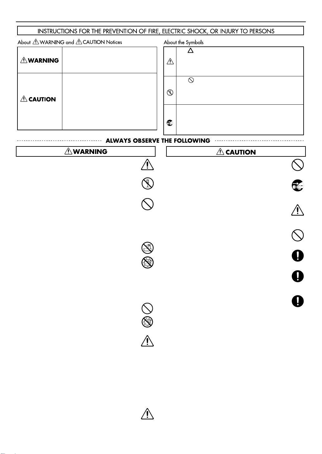
USING THE UNIT SAFELY
Used for instructions intended to alert the
user to the risk of death or severe injury
should the unit be used improperly.
Used for instructions intended to alert the
user to the risk of injury or material
damage should the unit be used
improperly.
* Material damage refers to damage or
other adverse effects caused with
respect to the home and all its
furnishings, as well to domestic animals
or pets.
001
•
Before using this unit, make sure to read the
instructions below, and the Owner’s Manual.
......................................................................................................................................
002a
•
Do not open or perform any internal modifications on
the unit.
......................................................................................................................................
003
•
Do not attempt to repair the unit, or replace parts
within it (except when this manual provides specific
instructions directing you to do so). Refer all servicing
to your retailer, the nearest Roland Service Center, or
an authorized Roland distributor, as listed on the
“Information” page.
......................................................................................................................................
004
•
Never use or store the unit in places that are:
•
Subject to temperature extremes (e.g., direct sunlight in an
enclosed vehicle, near a heating duct, on top of heat-generating equipment); or are
•
Damp (e.g., baths, washrooms, on wet floors); or are
•
Humid; or are
•
Exposed to rain; or are
•
Dusty; or are
•
Subject to high levels of vibration.
......................................................................................................................................
011
•
Do not allow any objects (e.g., flammable material,
coins, pins); or liquids of any kind (water, soft drinks,
etc.) to penetrate the unit.
The symbol alerts the user to important instructions or
warnings.The specific meaning of the symbol is
determined by the design contained within the triangle. In
the case of the symbol at left, it is used for general
cautions, warnings, or alerts to danger.
The symbol alerts the user to items that must never be
carried out (are forbidden). The specific thing that must
not be done is indicated by the design contained within
the circle. In the case of the symbol at left, it means that
the unit must never be disassembled.
The ● symbol alerts the user to things that must be
carried out. The specific thing that must be done is
indicated by the design contained within the circle. In the
case of the symbol at left, it means that the power-cord
plug must be unplugged from the outlet.
014
•
Protect the unit from strong impact.
(Do not drop it!)
.......................................................................................................................................
022c
•
Before installing the AR-NT1R, you must first always
turn off the AR-3000/AR-3000R and unplug its power
cord.
.......................................................................................................................................
104
•
Try to prevent cords and cables from becoming
entangled. Also, all cords and cables should be placed
so they are out of the reach of children.
.......................................................................................................................................
106
•
Never climb on top of, nor place heavy objects on the
unit.
.......................................................................................................................................
108c
•
Disconnect all cords coming from external devices
before moving the unit.
.......................................................................................................................................
115b
•
Install the circuit board only into the specified unit (AR3000/AR-3000R). Remove only the specified screws
during the installation.
.......................................................................................................................................
118b
•
Keep the included screws in a safe place out of
children’s reach, so there is no chance of them being
swallowed accidentally.
.......................................................................................................................................
......................................................................................................................................
012d
•
Immediately turn the power off, and request servicing
by your retailer, the nearest Roland Service Center, or
an authorized Roland distributor, as listed on the
“Information” page when:
•
If smoke or unusual odor occurs
•
Objects have fallen into, or liquid has been spilled onto the
unit; or
•
The unit has been exposed to rain (or otherwise has
become wet); or
•
The unit does not appear to operate normally or exhibits a
marked change in performance.
......................................................................................................................................
013
•
In households with small children, an adult should
provide supervision until the child is capable of
following all the rules essential for the safe operation of
the unit.
......................................................................................................................................
2
Page 3
IMPORTANT NOTES
Power Supply
307
•
Before connecting this unit to other devices, turn off the power
to all units. This will help prevent malfunctions and/or damage
to speakers or other devices.
Placement
352a
•
This device may interfere with radio and television reception.
Do not use this device in the vicinity of such receivers.
352b
•
Noise may be produced if wireless communications devices,
such as cell phones, are operated in the vicinity of this unit.
Such noise could occur when receiving or initiating a call, or
while conversing. Should you experience such problems, you
should relocate such wireless devices so they are at a greater
distance from this unit, or switch them off.
355b
•
When moved from one location to another where the
temperature and/or humidity is very different, water droplets
(condensation) may form inside the unit. Damage or
malfunction may result if you attempt to use the unit in this
condition. Therefore, before using the unit, you must allow it to
stand for several hours, until the condensation has completely
evaporated.
Maintenance
401a
•
For everyday cleaning wipe the unit with a soft, dry cloth or
one that has been slightly dampened with water. To remove
stubborn dirt, use a cloth impregnated with a mild, nonabrasive detergent. Afterwards, be sure to wipe the unit
thoroughly with a soft, dry cloth.
402
•
Never use benzine, thinners, alcohol or solvents of any kind, to
avoid the possibility of discoloration and/or deformation.
Additional Precautions
558a
•
To avoid disturbing your neighbors, try to keep the unit’s
volume at reasonable levels. You may prefer to use
headphones, so you do not need to be concerned about those
around you (especially when it is late at night).
559a
•
When you need to transport the unit, package it in the box
(including padding) that it came in, if possible. Otherwise, you
will need to use equivalent packaging materials.
Additional Precautions
901
•
To avoid the risk of damage to internal components that can
(continued)
be caused by static electricity, please carefully observe the
following whenever you handle the board.
1
•
Before you touch the board, always first grasp a metal object (such as
a water pipe), so you are sure that any static electricity you might
have been carrying has been discharged.
2
•
When handling the board, grasp it only by its edges. Avoid touching
any of the electronic components or connectors.
3
•
When handling the board, grasp it only by the panel or the board’s
edges. Avoid touching any of the electronic components or
connectors.
4
•
Before you connect any cables, make sure they do not carry a static
electricity charge. Such charges can be transmitted, for example, if
the other end of the cable has been in contact with a carpet (or other
object) where there is a static electricity buildup.
5
•
Save the bag in which the board was originally shipped, and put the
board back into it whenever you need to store or transport it.
901(F)
•
Veuillez suivre attentivement les instructions suivantes quand
vous manipulez la carte afin d’éviter tout risque
d’endommagement des pièces internes par l’électricité
statique.
1
•
Toujours toucher un objet métallique relié à la terre (comme un
tuyau par exemple) avant de manipuler la carte pour vous décharger
de l’électricité statique que vous auriez pu accumuler.
2
•
Lorsque vous manipulez la carte, la tenir par les côtés. Évitez de
toucher aux composants ou aux connecteurs.
3
•
Lorsque vous manipulez la carte, la tenir par les côtés de la plaque ou
par les côtés du circuit imprimé. Évitez de toucher aux composants
ou aux connecteurs.
4
•
Avant de connecter tout câble, assurez-vous qu’il ne contient aucune
charge d’électricité statique. De telles charges peuvent être transmises, par exemple, si l’autre extrémité du câble touche à un tapis
(ou autre objet) où il y a accumulation d’électricité statique.
5
•
Conservez le sachet d’origine dans lequel était la carte lors de l’envoi
et remettez la carte dedans si vous devez la ranger ou la transporter.
Model Name :
Type of Equipment :
Responsible Party :
Address :
Telephone :
For the USA
DECLARATION OF CONFORMITY
Compliance Information Statement
AR-NT1R
Network Bord
Roland Systems Group U.S.
425 Sequoia Drive Suite 114, Bellingham, Washington, 98226 USA
(360) 594-4282
3
Page 4

Installing the Option Board
The AR-NT1R comes with a cover designed to block electromagnetic noise.
Be sure to follow the procedure described below to install the cover included with the AR-NT1R in place of the
cover removed from the AR-3000/AR-3000R.The outer surface of the cover included with the AR-NT1R is painted
black, and the inner surface is unpainted metal.
1.
Switch off the AR-3000/AR-3000R and unplug its power
cord from the power outlet.
* To prevent malfunction and/or damage to speakers or other
devices, always turn down the volume, and turn off the power on all
devices before making any connections.
2.
Remove the two screws for the option board slot in the
rear panel and detach the cover.
3.
Remove the four screws for the option board space in the
top panel and detach the cover.
fig.00
3
2
4.
Insert the connector board from the rear panel.
fig.01
5.
Use the two screws included with the AR-NT1R to attach
the connector board.
* Do not use the two screws you removed in step 2. Be sure to use the
screws included with the AR-NT1R.
6.
Insert the cable of the connector board into the connector
on the option board.
fig.02
7.
Completely insert the connector for the option board into
the connector on the unit.
When doing this, make sure that the heads of the three
circuit board holders extend from the option board.
fig.03
* Do not touch any of the printed circuit pathways or connection
terminals.
912
* Never use excessive force when installing a circuit board. If it doesn’t
fit properly on the first attempt, remove the board and try again.
Use the retainer included with the option board to turn
8.
the circuit board holders to LOCK, securing the option
board in place.
fig.04
LOCK
913
* When circuit board installation is complete, double-check your
work.
Raise up the circuit board’s flat spring. Then, with the
9.
cover’s black surface facing upwards, place the cover in
position over the option-board space. Check to make sure
that the flat spring is making proper contact with the
cover.
fig.04
* Do not use the cover you removed in step 2. Be sure to use the
screws included with the AR-NT1R.
* When doing this, make sure that the cover for the option-board
space contacts the flat spring on the circuit board, and as a result is
slightly elevated. If it is not elevated, bend the flat spring so that it
stands up straighter, and makes contact with the cover.
10.
Use the four screws you removed in step 3 to attach the
cover for the option board space.
4
Page 5

Installation de la carte d’option
L’AR-NT1R est livré avec un couvercle conçu pour bloquer le bruit électromagnétique.
Assurez-vous de suivre la procédure ci-dessous pour installer le couvercle fourni avec l’AR-NT1R à la place du
couvercle retiré de l’AR-3000/AR-3000. La surface extérieure du couvercle fourni avec l’AR-NT1R est peinte en
noir et la surface intérieure n’est pas peinte.
1.
Couper le contact sur l’appareil AR-3000/AR-3000R et
débrancher la prise d’alimentation.
2.
Retirer du panneau arrière les deux vis de la fente pour la
carte d’option et retirer le couvercle.
Retirer du panneau supérieur les quatre vis pour la carte
3.
d’option et retirer le couvercle.
fig.00
3
2
Insérer la carte de connexion par le panneau arrière.
4.
fig.01
5. Fixer la carte de connexion à l’aide des deux vis fournies
avec l’AR-NT1R.
* Ne pas utiliser les deux vis retirées à l’étape 2. Utiliser les vis fournies
avec l’AR-NT1R.
Insérer le câble de la carte de connexion dans le
6.
connecteur sur la carte d’option.
fig.02
7.
Insérer à fond le connecteur de la carte d’option dans le
connecteur de l’unité.
S’assurer que les têtes des trois supports de circuit
imprimé se prolongent au-delà de la carte d’option.
fig.03
911(F)
* Ne pas toucher aux circuits imprimés ou aux connecteurs.
912(F)
* Ne jamais forcer lors de l’installation de la carte de circuits imprimés.
Si la carte s’ajuste mal au premier essai, enlevez la carte et recommencez l’installation.
Utiliser la patte de fixation fournie avec la carte d’option
8.
pour tourner les supports de carte de circuits imprimés en
position VERROUILLÉ (LOCK) afin de maintenir la carte
d’option.
fig.04
LOCK
913(F)
* Quand l’installation de la carte de circuits imprimés est terminée,
revérifiez si tout est bien installé.
Relever le ressort plat de la carte de circuits imprimés.
9.
Déposer ensuite le couvercle au-dessus de l’espace
destiné à la carte en option, la surface noire du couvercle
vers le haut. S’assurer que le ressort plat est bien en
contact avec le couvercle.
fig.04
* N’utilisez pas le couvercle retiré à l’étape 2. Utilisez les vis fournies
avec l’AR-NT1R.
* En même temps, assurez-vous que le couvercle de l’espace prévu
pour la carte d’option est en contact avec le ressort plat et non avec
la carte de circuits imprimés. Sinon, courbez le ressort plat pour qu’il
forme un angle droit et touche le couvercle, sans toucher la carte de
circuits imprimés.
10.
Utiliser les quatre vis retirées à l’étape 3 pour fixer le
couvercle de l’espace destiné à la carte d’option.
5
Page 6

Network Settings
When you have finished installing the option board , follow the steps below to make the network settings.
For details of the various items for which settings can be made, refer to the Reference Manual, mentioned later in this document.
Switch on the power and press the [MODE] button.
1.
The [MODE] indicator lights up and the Setting Item Selection
screen appears.
* This unit is equipped with a protection circuit. A brief interval (a few
seconds) after power up is required before the unit will operate
normally.
Use the [SELECT] dial to select “10.2 Network Address,”
2.
then press the dial.
Turn the [SELECT] dial to select the setting value, then
3.
press the dial.
The entry location shown below is highlighted.
fig.
Repeat the operation in step 3. Once you’ve finished
4.
supplying values for the settings, press the [ENTER]
button.A screen asking you to confirm the write
procedure appears.
(The confirmation screen appears even if you enter the final
item and press the dial.)
To write the settings to the unit, press the [ENTER] button.
5.
To cancel, use the [SELECT] dial to choose “NO,” then press
the [ENTER] button.
You are returned to the Setting Item Selection screen.
* The settings for the network address will take effect the next time
you power up.
Next, make the setting for the network password.
6.
Should you not require the use of a password, you can
proceed to step 11.
Use the [SELECT] dial to select “10.3 Network Password,” then
press the dial.
Turn the [SELECT] dial to select “ON,” then press the dial.
7.
fig.
Turn the [SELECT] dial to select the characters for the
8.
password (letters or numbers), then press the dial.
fig.
9.
Repeat step 7. When you have finished entering the
password (5 to 8 characters), press the [ENTER] button.
A screen asking you to confirm the write procedure appears.
(The confirmation screen appears even if you enter the final
item and press the dial.)
10.
To write the settings to the unit, press the [ENTER] button.
To cancel, use the [SELECT] dial to choose “NO,” then press
the [ENTER] button.
You are returned to the Setting Item Selection screen.
11.
Press the [MODE] button.
The [MODE] indicator goes out, and you’re returned to the
screen that normally appears after you switch on the power.
* While making settings, you can go back to the previous entry
location (highlighted) by pressing the [PAUSE (BACK)] button.
* If you press the [MODE] button while making settings, a screen
prompting you to confirm that you want to cancel the settings
you’ve made up to that point will appear. Note that if you select
“YES” and press the [ENTER] button, you’ll be returned to the usual
screen, and any settings you may have made up to then will be
discarded.
Network-related Reference Materials
In addition to the owner’s manual, the document “AR-NT1R Reference” for the network board is available for purchase.
The PDF file can be download free of chrge from the following URL
http://www.rssamerica.com/
The “AR-NT1R Reference” covers such topics as the following.
•
Setup
•
Overviews, detailed descriptions, and lists of commands
•
Examples of algorithms used
6
Page 7

For EU Countries
This product complies with the requirements of EMC Directive 2004/108/EC.
For the USA
FEDERAL COMMUNICATIONS COMMISSION
RADIO FREQUENCY INTERFERENCE STATEMENT
This equipment has been tested and found to comply with the limits for a Class B digital device, pursuant to Part 15 of the
FCC Rules. These limits are designed to provide reasonable protection against harmful interference in a residential
installation. This equipment generates, uses, and can radiate radio frequency energy and, if not installed and used in
accordance with the instructions, may cause harmful interference to radio communications. However, there is no guarantee
that interference will not occur in a particular installation. If this equipment does cause harmful interference to radio or
television reception, which can be determined by turning the equipment off and on, the user is encouraged to try to correct the
interference by one or more of the following measures:
– Reorient or relocate the receiving antenna.
– Increase the separation between the equipment and receiver.
– Connect the equipment into an outlet on a circuit different from that to which the receiver is connected.
– Consult the dealer or an experienced radio/TV technician for help.
This device complies with Part 15 of the FCC Rules. Operation is subject to the following two conditions:
(1) this device may not cause harmful interference, and
(2) this device must accept any interference received, including interference that may cause undesired operation.
Unauthorized changes or modification to this system can void the users authority to operate this equipment.
This equipment requires shielded interface cables in order to meet FCC class B Limit.
For Canada
NOTICE
This Class B digital apparatus meets all requirements of the Canadian Interference-Causing Equipment Regulations.
AVIS
Cet appareil numérique de la classe B respecte toutes les exigences du Règlement sur le matériel brouilleur du Canada.
For C.A. US (Proposition 65
WARNING
This product contains chemicals known to cause cancer, birth defects and other reproductive harm, including lead.
For EU Countries
)
7
Page 8

Information
When you need repair service, call your nearest Roland Service Center or authorized Roland distributor in your country as
shown below.
ASIA
INDONESIA
PT. Citra IntiRama
JL. Cideng Timur No. 15J-15O
Jakarta Pusat
INDONESIA
TEL: (021) 632-4170
CHINA
Roland Shanghai Electronics Co.,Ltd.
5F. No.1500 Pingliang Road
Shanghai 200090, CHINA
TEL: (021) 5580-0800
Roland Shanghai Electronics Co.,Ltd.
(BEIJING OFFICE)
10F. No.18 3 Section Anhuaxili
Chaoyang District Beijing
100011 CHINA
TEL: (010) 6426-5050
KOREA
KOREA AVICS CO., LTD.
Unit B-2208, Woolimblue9,
#240-21, Yeomchang-dong,
Gangseo-gu, Seoul, Korea
Tel: 02-322-3264
TAIWAN
ROLAND TAIWAN
ENTERPRISE CO., LTD.
Room 5, 9fl. No. 112 Chung Shan
N.Road Sec.2, Taipei, TAIWAN,
R.O.C.
TEL: (02) 2561 3339
SINGAPORE/
MALAYSIA
Roland Asia Pacific Sdn.
Bhd.
45-1, Block C2, Jalan PJU 1/39,
Dataran Prima, 47301 Petaling
Jaya, Selangor, MALAYSIA
TEL: 3-7805-3263
CENTRAL/LATIN
AMERICA
BRAZIL
Roland Brasil Ltda.
Rua San Jose, 211
Parque Industrial San Jose
Cotia - Sao Paulo - SP, BRAZIL
TEL: (011) 4615 5666
Other CENTRAL/
LATIN AMERICA
Roland Systems Group U.S.
425 Sequoia Drive Suite 114,
Bellingham, Washington,
98226 USA
TEL: 360-594-4282
EUROPE
AUSTRIA/BELGIUM/
FRANCE/GERMANY/
HOLLAND/
LUXEMBOURG/
PORTUGAL/SPAIN/
SWITZERLAND
Roland Iberia, S.L.
Paseo García Faria, 33-35
08005 Barcelona SPAIN
TEL: 93 493 91 00
CROATIA
ART-CENTAR
Degenova 3.
HR - 10000 Zagreb
TEL: (1) 466 8493
CZECH REP.
CZECH REPUBLIC
DISTRIBUTOR s.r.o
Voctárova 247/16
CZ - 180 00 PRAHA 8,
CZECH REP.
TEL: (2) 830 20270
DENMARK
Roland Scandinavia A/S
Nordhavnsvej 7, Postbox 880,
DK-2100 Copenhagen
DENMARK
TEL: 3916 6200
FINLAND
Roland Scandinavia As,
Filial Finland
Elannontie 5
FIN-01510 Vantaa, FINLAND
TEL: (0)9 68 24 020
HUNGARY
Roland East Europe Ltd.
Warehouse Area ‘DEPO’ Pf.83
H-2046 Torokbalint, HUNGARY
TEL: (23) 511011
NORWAY
Roland Scandinavia Avd.
Kontor Norge
Lilleakerveien 2 Postboks 95
Lilleaker N-0216 Oslo
NORWAY
TEL: 2273 0074
POLAND
ROLAND POLSKA SP. Z O.O.
ul. Kty Grodziskie 16B
03-289 Warszawa, POLAND
TEL: (022) 678 9512
ROMANIA
FBS LINES
Piata Libertatii 1,
535500 Gheorgheni, ROMANIA
TEL: (266) 364 609
RUSSIA
MuTek
Dorozhnaya ul.3,korp.6
117 545 Moscow, RUSSIA
TEL: (095) 981-4967
SLOVAKIA
DAN Acoustic s.r.o.
Povazská 18.
SK - 940 01 Nové Zámky
TEL: (035) 6424 330
SWEDEN
Roland Scandinavia A/S
SWEDISH SALES OFFICE
Danvik Center 28, 2 tr.
S-131 30 Nacka SWEDEN
TEL: (0)8 702 00 20
UKRAINE
EURHYTHMICS Ltd.
P.O.Box: 37-a.
Nedecey Str. 30
UA - 89600 Mukachevo,
UKRAINE
TEL: (03131) 414-40
UNITED KINGDOM/
IRELAND
Roland (U.K.) Ltd.
Atlantic Close, Swansea
Enterprise Park, Swansea
SA7 9FJ,
UNITED KINGDOM
TEL: (01792) 702701
OCEANIA
AUSTRALIA/
NEW ZEALAND
Roland Corporation
Australia Pty.,Ltd.
38 Campbell Avenue
Dee Why West, NSW 2099
AUSTRALIA
For Australia
TEL: (02) 9982 8266
For New Zealand
TEL: (09) 3098 715
NORTH AMERICA
CANADA
Roland Canada Ltd.
(Head Office)
5480 Parkwood Way, Richmond
B. C., V6V 2M4 CANADA
TEL: (604) 270 6626
Roland Canada Ltd.
(Toronto Office)
170 Admiral Boulevard
Mississauga ON L5T 2N6
CANADA
TEL: (905) 362 9707
U. S. A.
Roland Systems Group U.S.
425 Sequoia Drive Suite 114,
Bellingham, Washington,
98226 USA
TEL: 360-594-4282
As of Jan. 1, 2009 (RSS)
 Loading...