


Parameter Guide
© 2021 Roland Corporation
04

Contents
AE-30 Functions available only on the AE-30.
AE-20 Functions available only on the AE-20.
Settings Used on this Instrument .............. 3
System Parameters .................................. 3
Scene Parameters .................................... 10
Assign Parameters ................................... 10
MIDI Parameters ..................................... 12
Data Backup and Restore Operations ......... 14
Formatting a USB Flash Drive ......................... 14
Backing Up/Restoring System Settings ................ 14
Backing Up/Restoring Scene Settings ................. 15
Installing a SOUND PACK/WAVE EXPANSION . 17
Preparing the Sound Files ............................ 17
Importing a SOUND PACK ............................ 17
AE-30 Installing a WAVE EXPANSION ................. 18
AE-30 Managing the WAVE EXPANSION Data ......... 18
Initializing a User License ............................. 19
How the Scenes are Structured ................. 20
ZEN-Core Tone ...................................... 20
SuperNATURAL Tone ................................. 20
Drum Kit ............................................ 21
Scene Parameters ................................ 22
SCENE/COMMON .................................... 22
SCENE/ASSIGN (INT) ................................. 22
SCENE/CONTROL SOURCE (INT) ....................... 23
SCENE/ASSIGN (MIDI) ................................ 23
SCENE/CONTROL (MIDI) .............................. 25
SCENE/PART ......................................... 25
SCENE/MODE ....................................... 25
SCENE/RANGE ....................................... 26
SCENE/PITCH ........................................ 26
SCENE/OFFSET ...................................... 26
SCENE/EQ ........................................... 27
SCENE/OUTPUT ..................................... 27
SCENE/CONTROL .................................... 27
SCENE/CONTROL RX ................................. 28
SCENE/IFX ........................................... 28
SCENE/CHORUS ..................................... 29
Chorus Parameters ................................. 29
SCENE/DELAY ....................................... 30
Delay Parameters ................................... 30
SCENE/REVERB ...................................... 32
Reverb Parameters ................................. 32
Tone Parameters ................................. 35
TONE/COMMON ..................................... 35
TONE/STRUCTURE ................................... 37
TONE/MFX .......................................... 39
TONE/PARTIAL ....................................... 40
TONE/PARTIAL/OSC .................................. 40
TONE/PARTIAL/RANGE ............................... 41
TONE/PARTIAL/PITCH ................................ 42
TONE/PARTIAL/FILTER ................................ 43
TONE/PARTIAL/AMP ................................. 45
TONE/PARTIAL/LFO1, LFO2 ........................... 46
2
TONE/PARTIAL/PARTIAL EQ ........................... 48
TONE/PARTIAL/OUTPUT .............................. 48
TONE/PARTIAL/CONTROL ............................ 48
TONE/PARTIAL/MATRIX CONTROL ..................... 49
MFX/IFX Parameters ............................. 51
Thru ................................................ 51
Equalizer ............................................ 51
Low Boost ........................................... 51
Enhancer ............................................ 51
Auto Wah ........................................... 52
Humanizer .......................................... 52
Speaker Sim (Speaker Simulator) ...................... 53
Phaser 1 ............................................ 53
Tremolo ............................................. 54
Auto Pan ............................................ 54
VK Rotary ........................................... 54
Chorus .............................................. 55
Flanger ............................................. 55
Step Flanger ......................................... 56
Hexa-Chorus ........................................ 56
Space-D. . . . . . . . . . . . . . . . . . . . . . . . . . . . . . . . . . . . . . . . . . . . . 57
Overdrive ........................................... 57
Distortion ........................................... 57
T-Scream ............................................ 57
Guitar Amp Sim
Compressor ......................................... 59
Limiter .............................................. 59
Delay ............................................... 59
Mod Delay (Modulation Delay) ....................... 60
3Tap Pan Dly (3 Tap Pan Delay) ........................ 60
Tape Echo ........................................... 61
LOFI Comp (LOFI Compress) .......................... 61
Pitch Shifter ......................................... 61
2V Pshifter (2 Voice Pitch Shifter) ...................... 62
Gt (Guitar Amp Simulator) -> Delay .................... 62
CE-1 ................................................ 63
SBF-325 ............................................. 63
SDD-320 (DIMENSION D) ............................. 63
2Tap Pan Dly (2 Tap Pan Delay) ........................ 64
Fuzz ................................................ 64
JUNO-106 Chorus .................................... 64
Exciter .............................................. 64
(Guitar Amp Simulator) ..................... 58
Control Change List ............................. 66
Fingering Chart .................................. 67
Sax ................................................. 67
Recorder ............................................ 68
Electronic Wind ...................................... 69
Trumpet ............................................ 70
Left Hand ........................................... 71
Right Hand .......................................... 72
Flute ................................................ 73
Clarinet ............................................. 75

Settings Used on this Instrument
System Parameters
Indication (Parameter)
Master Tuning
Transpose Mode
AE-30
Transpose Knob Mode
AE-20
Volume Knob Mode
System Tranpose
Display Contrast
Display O Time
Auto O
Speaker Volume
Output Volume
Speaker Setting
Output Mode
Hold Mode
Breath Curve
Value Explanation
415.3–466.2 (Hz)
Switches the operating mode for transpose.
System The System Transpose value is used as the transpose value of the instrument.
Scene
These parameters congure the functions for the AE-30 [TRANSPOSE] knob or the AE-20 [VOLUME] knob.
System Transpose The System Transpose parameter changes when you operate the knob.
Speaker Volume The volume of the built-in speakers changes when you operate the knob.
Output Volume
Speaker & Output
-5 (G)–0 (C)–+6 (F#)
1–5
Always On, 3sec, 10sec,
30sec, 1–3min
Always On, 5min, 30min
0–11 Sets the volume of the built-in speakers.
0–11
These parameters are the speaker settings.
O Sound is not output from the built-in speakers.
On Sound is output from the built-in speakers.
Auto
Stereo, Mono
Sets the “hold mode,” which sustains notes even after you stop blowing.
O Notes are not sustained.
Breath
Key Pressing the performance keys produce notes according to your ngering.
Species how the sound responds to the force of your breath (breath sensitivity).
L5–L1
M
H1–H5
Changes the system tuning.
* The displayed value is the frequency of the A key.
The transposition will be as specied by the scene.
* When you change System Transpose, the System Transpose value is used even when a
transpose value is already set for the scene. When you change the scene afterwards, the
scene’s transpose value is used.
The volume for headphones connected to the PHONES jack, or of the signal output from
the OUTPUT jack changes when you operate the knob.
The volume of the built-in speakers and of headphones connected to the PHONES jack, as
well as the signal output from the OUTPUT jack simultaneously changes when you operate
the knob.
Sets the system transpose value.
Sets the display contrast.
Larger values make the display brighter.
Sets the time it takes for the display to turn o when the instrument is not being used.
When set to “Always On,” the display is always on.
When you press the [SCENE] or [MENU] button while the display is o, the display turns
back on.
Sets the time before the instrument automatically turns o.
The power to this unit will be turned o automatically after a predetermined amount of
time has passed since it was last used for playing music, or its buttons or controls were
operated (Auto O function).
If you don’t want the unit to turn o automatically, change this setting to “Always On.”
Species the volume that is output from the OUTPUT jack or from headphones connected
to the PHONES jack.
Sound is not output from the built-in speakers if headphones or a cable are connected to
the PHONES jack.
Sets whether the audio signal output from the PHONES or OUTPUT jack is outputted in
stereo or in mono.
Notes are sustained at the volume they are played when you blow once.
Inhale to stop the note.
We recommend these settings if you’re a beginning wind
instrument player.
Fortissimo () can be produced even by blowing relatively
softly.
This is the usual setting.
We recommend these settings for experienced wind
instrument players.
Fortissimo () is produced only when you blow quite strongly.
L5
Level
L1
M
Breath force
H1
H5
3

Settings Used on this Instrument
Indication (Parameter)
Breath Adjust
Bite Ctrl Mode
Bite Center (Sax)
Bite Sense (E-Wind)
Bite Calibration
Value Explanation
Adjusts the strength of breath at which sound starts being
heard.
1–50
The larger the value, the stronger you must blow to make a
sound.
These parameters set how the bite sensor controls the sound.
O Turns o the bite sensor control.
Reducing the strength of your bite on the reed makes the pitch fall.
Sax
Weakening the strength of your bite on the reed
lowers the pitch
Cyclically varying the strength of your bite on the reed applies vibrato.
E-Wind
Apply vibrato by repeatedly strengthening and weakening
the strength of your bite on the reed
This sets how much bite is applied to the reed (bite center) when playing normally.
Auto, 1–70
When set to “Auto,” this is automatically set.
* You can also set the bite center by pressing the +2 octave and -2 octave keys at the same
time with the mouthpiece in your mouth, as when you’re usually playing.
Sets the sensitivity when Bite Ctrl Mode is set to “E-Wind.”
1–10
Increase this value if you want to make the eect easier to apply; lower this value if the
eect is too strong.
Use this parameter to adjust (calibrate) the bite sensor.
1. Select “Bite Calibration,” and then press the
[MENU] button.
2. Use your ngers to hold the reed while
“ãNO YESâ” is shown.
Level
Breath force
Breath Adjust
3. Press the [â] (YES) button while still holding the
reed.
“Adjusting now...” appears, and calibration begins
automatically.
The internal digital volume is automatically
adjusted.
4. Press the [MENU] button when “Press MENU to
save” appears.
“Saving...” Ó “Complete” appears, and the calibration
value is saved.
Bend Range Source
Bend Range Bite Dn
Bend Range Bite Up
Bend Range Ctrl
Bend Range Mode
AE-30
Thumb Pad Sense
System, Scene
0–2400 (cent)
0–24
Selects whether the bend range in system settings (System) or the bend range set in each
scene (Scene) is used when operating the pitch bend.
Sets the bend range in cents, when “Bend Down” or “Bend Up”
is assigned to the bite controller.
Sets the bend range in semitones, when “Bend Up” or “Bend
Down” is assigned to the thumb lever or to another controller.
These parameters switch between bend range modes.
Either the Bend Range Bite, AE-30 Bend Range Motion or Bend Range Ctrl (whichever is
larger) is used for the bend range.
Normal
When you use both bite control and the thumb lever or other bend controls together, the
bend range is limited to the maximum or minimum value and does not operate beyond
this.
Advance
O, 1–10
Automatically calculates the bend range using the combination of Bend Range
Bite,
AE-30 Bend Range Motion and Bend Range Ctrl.
Sets how much the thumb pad aects the sound.
Larger values produce a greater eect.
5. Take your ngers o the reed.
* This is enabled when the
Bend Range Source is
“System.”
4

Settings Used on this Instrument
Indication (Parameter)
AE-30
Motion Ctrl Mode
AE-30
Motion_1 Setting
Motion_2 Setting
AE-30
Motion Sense (Vib)
AE-30
Bend Range Motion Dn
Bend Range Motion Up
Asgn Src Breath
Asgn Src Bite
Asgn Src Lever
AE-30
Asgn Src Thumb Pad
AE-30
Asgn Src Motion
Asgn Src S1/S2
Asgn Src Key
Harmony Source
Value Explanation
These parameters set how the motion sensors control the sound.
O
Normal
Turns o the motion sensor control.
Tilting the Aerophone controls the functions that are assigned in the Assign parameters.
The tilt detection range is set in Motion_1 Setting and Motion_2 Setting.
Lets you controls the pitch when you make cyclic changes to how the Aerophone is tilted.
Gives a vibrato-like eect when you repeatedly move the Aerophone up and down.
Vibrato
These parameters congure the detection range of the motion sensors.
Elevation Tilt
MIDI controller value
127
0
0–180 °
Elevation
Tilt
64
0
-90–90°
The motion of lifting the Aerophone up is used. This works through the range of tilting the
instrument up to 180º upwards.
The motion of tilting the Aerophone either to the left or to the right is used. This works
through the range of tilting the instrument up to 90º to the left or right.
Tilt Full
127127
-90–90°
1270
64
The motion of tilting the Aerophone either to the left or to the right is used. The base value
Tilt Full
is when the instrument is tilted 90º to the left, and this works through the range of tilting
the instrument up to 90º to the right.
Tilt Left
Tilt Right
1–10
0–2400 (cent)
The motion of tilting the Aerophone to the left is used. This works through the range of
tilting the instrument up to 90º to the left.
The motion of tilting the Aerophone to the right is used. This works through the range of
tilting the instrument up to 90º to the right.
Sets the sensitivity when Motion Ctrl Mode is set to “Vibrato.” Increase this value if you want
to make the eect easier to apply; lower this value if the eect is too strong.
Sets the bend range in cents, when “Bend Up/Down” is assigned to the motion control.
* This is enabled when Bend Range Source is “System.”
Selects whether to use the system settings (System) or the settings in each scene (Scene)
for the Assign or MIDI parameter that is assigned to the breath control.
Selects whether to use the system settings (System) or the settings in each scene (Scene)
for the Assign or MIDI parameter that is assigned to the bite control.
Selects whether to use the system settings (System) or the settings in each scene (Scene)
for the Assign or MIDI parameter that is assigned to the thumb lever.
Selects whether to use the system settings (System) or the settings in each scene (Scene)
System, Scene
for the Assign or MIDI parameter that is assigned to the thumb pad.
Selects whether to use the system settings (System) or the settings in each scene (Scene)
for the Assign or MIDI parameter that is assigned to the motion control.
Selects whether to use the system settings (System) or the settings in each scene (Scene)
for the Assign or MIDI parameter that is assigned to the [S1]/[S2] buttons.
Selects whether to use the system settings (System) or the settings in each scene (Scene)
for the Assign or MIDI parameter that is assigned to the performance keys.
Selects whether to use the system harmony settings (System) or the harmony settings in
each scene (Scene).
Tilt Left Tilt Right
127
0
-90–0°
127
0
0–90°
5

Settings Used on this Instrument
Indication (Parameter)
Harmony 1
Harmony 2
Harmony 3
Harmony 4
Ctrl Source Select
System Ctrl Source 1
System Ctrl Source 2
System Ctrl Source 3
System Ctrl Source 4
Category Knob Mode
Value Explanation
Sets the pitch of the harmony notes that work when each controller function is set to “Harmony.”
Up to four harmony notes can be added.
* This is enabled when the Harmony Source is “System.”
Oct below (-12), 7th Maj below (-11), 7th min below (-10), 6th Maj below (-9), 6th min below (-8), 5th below (-7),
Tritone below (-6), 4th below (-5), 3rd Maj below (-4), 3rd min below (-3), 2nd Maj below (-2), 2nd min below (-1),
O,
2nd min above (+1), 2nd Maj above (+2), 3rd min above (+3), 3rd Maj above (+4), 4th above (+5), Tritone above (+6),
5th above (+7), 6th min above (+8), 6th Maj above (+9), 7th min above (+10), 7th Maj above (+11), Oct above (+12)
These parameters select whether to use the system settings or the scene settings for tone control.
System Uses System Control Source 1–4.
Scene Uses Control Source 1–4 for the scene.
O, CC01–31, CC33–95,
Bend, After Touch
Sets the function of the [CATEGORY] knob.
Category
User
Favorite
Sets the MIDI messages to use for tone control.
This lets you select a preset scene category by turning the knob.
Hold down the [à] button and turn the knob to select a favorite scene.
Hold down the [á] button and turn the knob to select a user scene bank.
This lets you select a user scene bank by turning the knob.
Hold down the [à] button and turn the knob to select a preset scene category.
Hold down the [á] button and turn the knob to select a scene that’s registered as a favorite.
This lets you select a scene registered as a favorite by turning the knob.
Hold down the [à] button and turn the knob to select a preset scene category.
Hold down the [á] button and turn the knob to select a user scene bank.
This turns the shortcut function on/o, which is useful for switching between scenes.
Scene Shortcut
Edit Conrm
Bluetooth
Bluetooth ID
O, On
O, On
O, On
O, 1–9
[SCENE] (à/á) button
Holding down the
[SCENE] (à) or (á)
button
Sets whether to show a conrmation message (On) or not (O) when a scene parameter is
edited and you select a dierent scene without saving your user scene.
Turns the Bluetooth function on/o.
If you are pairing with your smartphone in a location where there are multiple Aerophone units,
you can assign an ID to each unit. When you specify a Device ID, the specied number is added to
the end of the device name that is shown on app “Aerophone Pro Editor.”
(Example: “AE-30 AUDIO 1”, “AE-30 1”, etc.)
1
4
5
6
1
7
2
8
3
Scene number –1
Scene number +1
8
–
Eb Scene number –1
C Scene number +1
Select the user scene (U01-01–U01-08)
6

Settings Used on this Instrument
Indication (Parameter)
BT Audio Pairing
Value Explanation
1. Place the smartphone that you want to connect
near Aerophone.
2. Press the Aerophone’s [MENU] button.
The Menu screen appears.
3. Use the [-][+] (ã/â) buttons to select “BT Audio
Pairing,” and press the [MENU] button.
The cursor moves to the lower line, and the display
indicates “Yes” “No.”
(Pairing Start)
MEMO
If the Aerophone’s Bluetooth function is
o, use MENU to turn “Bluetooth” to “On” .
Smartphone
Aerophone
Use the [+](A) button to select “Yes.”
4.
The Bluetooth LED blinks, and the
Aerophone waits for pairing.
Turn on the Bluetooth function of your
5.
smartphone.
6. Tap “AE-30 AUDIO” or “AE-20 AUDIO” that
appears in the smartphone’s Bluetooth
“DEVICES” eld.
Aerophone and smartphone are paired. When pairing is
completed, a display like the following appears.
“AE-30 AUDIO” or “AE-20 AUDIO” is added to the “My devices” area, and shown as
“Connected.”
The screen indicates “Connected.”
Bluetooth Reset
MIDI Ctrl Sound
MIDI Ctrl PC
MIDI Ctrl BS
MIDI Speed
MIDI Velocity
USB Driver
Key Delay
Octave Key
Resets the Bluetooth settings. When reconnecting a smartphone that was connected prior to the reset, delete the
registration on your smartphone rst.
O, On Sets whether the internal sound engine is on/o when MIDI control mode is on.
O, On
When the MIDI control mode is on, this switches the program change message output on/
o.
O, On When the MIDI control mode is on, this switches the bank select (MSB, LSB) output on/o.
1–15 (ms) Sets the interval at which MIDI messages are output when MIDI control mode is on.
These parameters set the note-on velocity values for MIDI output.
Tongued The velocity value is determined by the strength of your tonguing.
Fixed 1–127 The specied value (a xed value) is used.
Sets the USB driver.
Choose this if you want to use the generic USB driver provided by your computer’s
Generic
operating system.
* Only MIDI is available.
Vendor Choose this if you want to use a USB driver downloaded from the Roland website.
Sets the time it takes for the performance keys to actually produce sound when you play
them.
0–10
Unintended notes can be sounded due to inconsistent ngering when you press or release
multiple keys simultaneously.
The larger the value, the less likely it is for unintended notes to sound.
The octave keys can be set to ±2 octaves, ±3 octaves, Sax1 or Sax2.
+3
Press simultaneously for +2
+1
Press simultaneously for +2
–1
–3
Oct2, Oct3
Sax1
Oct2 Oct3
+2
+1
–1
–2
This is the sax-compatible mode.
The upper octave key only raises the octave up +1.
This is the baritone sax-compatible mode.
Sax2
The upper octave key raises the octave up +1. The lower octave key lets you play all the way
down to the low A.
7

Settings Used on this Instrument
Indication (Parameter)
Fingering Mode
Value Explanation
Species the ngering mode.
For details on ngering in each mode, refer to “Fingering Chart” (p. 67).
Sax Sax ngering
Recorder ngering
Recorder
E-Wind
Trumpet
Left Hand Fingering that lets you perform using only the left hand
Right Hand Fingering that lets you perform using only the right hand
Flute
Clarinet
You can add, edit, or delete your preferred ngerings.
* Up to 36 ngering settings can be specied.
* In this mode, transpose and octave shift settings are ignored.
For details on the displayed note name and ngering, refer to “Fingering Chart” (p. 67).
This uses standard recorder ngering, with the pitch range expanded by the table key.
With this ngering, the side keys are disabled so that the note does not change even if you
inadvertently press the left or right side key.
Electronic wind instrument ngering
The same “C D E F G A B C” ngering as a standard sax or recorder, with key combinations that
raise/lower the pitch by a semitone.
1, 2, 3, 4, 5, 6, C The same “C D E F G A B C” ngering as a standard sax or recorder
Tc, G#, C# Raise by a semitone
Ta, Tf, Eb, B Lower by a semitone
Bb Lower by a whole tone
Trumpet ngering
This mode is close to the ngering of a typical brass instrument. Right-hand keys 4, 5, and 6
correspond to pistons 1, 2, and 3 of a trumpet.
Flute ngering
This uses standard ute ngering, with the pitch range expanded by the below keys.
x, C1, C2, C3 Raise by a semitone
p, B, C4, Tc, Ta Lower by a semitone
Bb Lower by a whole tone
Clarinet ngering
This uses standard clarinet ngering, with the pitch range expanded by the below keys.
C1 Raise by a semitone
p, C5 Lower by a semitone
User Fingering
How to add or edit
Select “User Fingering,” and then press the [MENU]
1.
button.
2. Press a performance key.
The note name appears. If there is no corresponding
note, indicates “NONE.”
3. While ngering the desired key, press the octave
key [+2].
+2
4. Use the [ã] [â] buttons to change the note name.
5. Press the [MENU] button.
A conrmation message appears.
6. To execute the write, press the [â] (YES) button.
If you decide to cancel the write, press the [ã] (NO)
button.
An added or disabled ngering is indicated by a “*”
to the right side of the note name.
How to delete
Select “User Fingering,” and then press the [MENU]
1.
button.
2. Press a performance key.
The note name appears. An added or disabled
ngering is indicated by a “*” in the screen.
3. While ngering the desired key, press the octave
key [+2].
4. Use the [ã] [â] buttons to choose “Del.”
5. Press the [MENU] button.
A conrmation message appears.
6. To execute the write, press the [â] (YES) button.
The “*” in the screen disappears.
If you decide to cancel the write, press the [ã] (NO)
button.
8

Settings Used on this Instrument
Indication (Parameter)
Key Function
Language
User Scene Set
Value Explanation
This function lets you disable the performance keys, and shift the pitch up/down a semitone or whole tone.
1. Select “Key Function” and then press a performance key.
The name of the key you pressed is shown.
2. Press the [MENU] button to move the cursor to the lower row.
3. Select a function.
4. Press the [MENU] button to move the cursor to the upper row.
O Disables the keys.
Sax Key The keys operate as normal performance keys.
Semitone Down The keys shift down a semitone.
Semitone Up The keys shift up a semitone.
Wholetone Down The keys shift down a whole tone.
Wholetone Up The keys shift up a whole tone.
English, Japanese,
Chinese
Registers the scene you are currently using as a user scene.
1. Select “User Scene Set” and then press the [MENU]
button.
Species the display language.
4. If you want to edit the name, press the [â] (YES)
button.
2. Use the [-][+] (ã/â) buttons to specify the user
scene number in which you want to save the
currently selected scene.
Moves cursor
Changes the character
3. Press the [MENU] button.
A screen appears, allowing you to edit the name of
the scene.
[–] [+] (ã/â) buttons
[SCENE] (à/á) buttons
[S1] button Insert one character
[S2] button Delete one character
5. Press the [MENU] button.
A conrmation message appears.
Registers the scene you are currently selecting as a
1. Select “Favorrite Set” and then press the [MENU]
button.
2. Use the [-][+] (ã/â) buttons or [SCENE CATEGORY]
knob to specify the favorite scene number in which
Favorite Set
Factory Reset
User Scene Clear Erases all user scenes/tones that are registered.
Version Displays the version of the unit’s system program.
you want to save the currently selected scene.
Returns the system settings to their factory-set state.
This operation does not erase the user scene / tone.
6. To write the scene, press the [+] (â) button.
If you decide not to write, press the [-] (ã) button.
favorite.
3. Press the [MENU] button.
A conrmation message appears.
4. To write the scene, press the [+] (â) button.
If you decide not to write, press the [-] (ã) button.
After writing is completed, the scene that you wrote
is shown.
9

Settings Used on this Instrument
Scene Parameters
Indication (Parameter)
Scene Volume 0–127
Scene Transpose -5–0–+6
Scene Octave Shift -3–0–+3
Scene Chorus 0–127 Sets the chorus depth for the scene.
Scene Reverb 0–127 Sets the reverb depth for the scene.
Scene Delay 0–127 Sets the delay depth for the scene.
Scene IFX Sw O, On Switches the IFX on/o for the scene.
All Eects O
Value Explanation
Species the volume of each scene.
Species the transposition (pitch shift) of each scene.
* If the system parameter’s Transpose Mode is “Scene,” this transpose value is applied
when you select the scene.
* When you change System Transpose after selecting a scene, the System
Transpose value is used as the transpose value of the instrument.
Species the octave shift setting of the scene.
–
Turns o all eects (chorus, reverb, delay and MFX) set for the scene.
To turn all eects o, press the [MENU] button and then press the [â] button.
Assign Parameters
You can assign functions to controllers such as the buttons and the thumb lever, and specify how the functions are controlled.
Maximum no. of assignable functions per controller
Breath
Bite Up/Down, AE-30 Thumb Pad
Lever Up/Down
AE-30 Motion
S1, S2, Side Key
8
4
2
2
2
* The Assign parameters work when the settings in “Asgn Src” (assign source) of each controller of the system are set to “System.”
If Asgn Src is set to “Scene,” each scene’s assignment settings are used (p. 5).
Assigning a continuously-variable controller (
* Indications of “***” in the table will contain the following names. The rst parameter for Breath is shown as “Breath_1”, the second parameter for
S1 is shown as “S1_2” and so on.
Breath_1–8, BiteDn_1–4, BiteUp_1–4, LeverDn_1–2, LeverUp_1–2,
* For controllers whose Func parameter is “O,” their parameters related to the assign settings are not shown.
Indication (Parameter)
*** Func
*** In Min
*** In Max
*** Out Min
*** Out Max
*** Mode
Value Explanation
See “Assign Function List”
(p. 12)
0–127
0–127
Species the operation mode.
Latch
Momentary
AE-30
Breath_1–Motion_2 /
AE-30 ThumbPad_1–4, AE-30 Motion_1–2
Specify the function that is assigned to a continuously-operated controller.
Specify the minimum value (Min) and
maximum value (Max) in which controller
operations are eective.
Specify the minimum value (Min) and
maximum value (Max) in which the assigned
function operates.
Each operation switches between Output Min Value and Output Max Value.
The function operates like a graph “Function assignment (continuous operation),”
according to how you operate the controller.
AE-20
Breath_1–LeverUp_2)
Ø “Function assignment (continuous
operation)”
10

Settings Used on this Instrument
Indication (Parameter)
Value Explanation
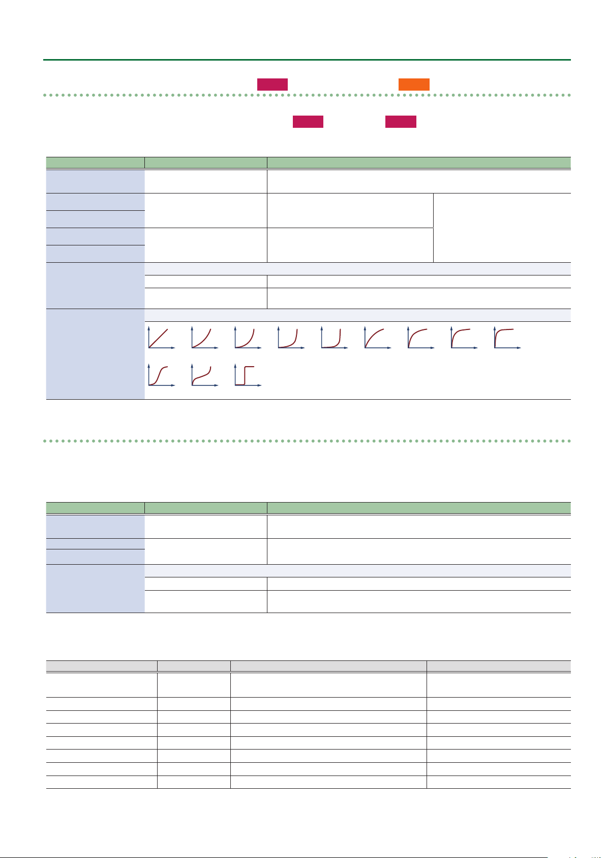
Species the operation curve when the operation mode is “Momentary.”
*** Curve
1: Linear 2: Exp L 3: Exp M1 4: Exp M2 5: Exp H
10: S-Shape 11: Reverse S 12: Step
Function assignment (continuous operation)
127
Out
Max
Out
Min
Operation
of function
0
Performer’s action
Input Min
Curve
Input Max
6: Log L 7: Log M1 8: Log M2 9: Log H
1: Linear 2: Exp L 3: Exp M1 4: Exp M2 5: Exp H
6: Log L 7: Log M1 8: Log M2 9: Log H 10: S-Shape
11: Reverse S 12: Step
127
11

Settings Used on this Instrument
Assigning a switch-type controller (S1_1–Ta_2)
* Indications of “***” in the table will contain the following names.
S1_1–2, S2_1–2, X_1–2, C1_1–2, C2_1–2, C3_1–2, C4_1–2, C5_1–2, Tc_1–2, Ta_1–2
* For controllers whose Func parameter is “O,” their parameters related to the assign settings are not shown.
Indication (Parameter)
*** Func See “Assign Function List” Species the function that is assigned when each controller is pressed.
*** Release Val
*** Press Val
*** Mode
Value Explanation
0–127
Species the operation mode.
Latch
Momentary
Specify the value when you take your nger o the button (Release) and the value
when you press the button (Press).
Each time you press the button, the Press Value and Release Value alternate.
The Press Value is applied while the button is pressed, and the Release Value is applied
while the button is released.
Assign Function List
Value Range Explanation Remarks
O
CC 01–31, CC33–95 0–127 Control change
Bend Down 0–127 Bend down
Bend Up 0–127 Bend up
After Touch 0–127 After touch (Channel Key Pressure)
Scene Down --- Select previous scene
Scene Up --- Select next scene
Favorite Down --- Select the previous favorite scene
Favorite Up --- Select the next favorite scene
Chorus Sw O, On Turns the chorus on.
Reverb Sw O, On Turns the reverb on.
Delay Sw O, On Turns the delay on.
IFX Sw O, On Turns the IFX on.
Unison Sw O, On Turns unison on.
Oct Down --- Octave down
Oct Up --- Octave up
Transpose Down ---
Transpose Up ---
Drone Sw O, On Turns the drone function on.
Harmony Sw O, On Turns the harmony on.
X-Fade 0–127 Crossfade
No function is assigned.
Not available for breath or bite
control
Transpose down (0 Ø -1 Ø ... -5 Ø +6 ... )
Transpose up (0 Ø +1 Ø ... +6 Ø -5 ... )
MIDI Parameters
You can assign a MIDI control function to each controller, and specify how control occurs.
Maximum no. of assignable functions per controller
Breath 8
Bite, AE-30 Thumb Pad
Lever Up/Down 2
AE-30 Motion
S1, S2, Side Key 2
* As with Assign, the MIDI control parameters work when the settings in “Asgn Src” (assign source) of each controller of the system are set to
“System.”
If Asgn Src is set to “Scene,” each scene’s MIDI control settings are used (p. 5).
12
4
2
Settings Used on this Instrument
Assigning a continuously-variable controller (
* Indications of “***” in the table will contain the following names.
Breath_1–8, BiteDn_1–4, BiteUp_1–4, LeverDn_1–2, LeverUp_1–2,
* For controllers whose Func parameter is “O,” their parameters related to the assign settings are not shown.
Indication (Parameter)
*** Func
*** In Min
*** In Max
*** Out Min
*** Out Max
*** Mode
*** Curve
Value Explanation
See “Assign Function (MIDI) List”
(p. 13)
0–127
0–127
Species the operation mode.
Latch
Momentary
Species the operation curve when the operation mode is “Momentary.”
1: Linear 2: Exp L 3: Exp M1 4: Exp M2 5: Exp H
AE-30
Breath_1–Motion_2 /
AE-30 ThumbPad_1–4, AE-30 Motion_1–2
Specify the function that is assigned to a continuously-operated controller.
Specify the minimum value (Min) and
maximum value (Max) in which controller
operations are eective.
Specify the minimum value (Min) and
maximum value (Max) in which the assigned
function operates.
Each operation switches between Output Min Value and Output Max Value.
The function operates like a graph “Function assignment (continuous operation),”
according to how you operate the controller.
6: Log L 7: Log M1 8: Log M2 9: Log H
AE-20
Breath_1–LeverUp_2)
Ø “Function assignment (continuous
operation)” (p. 11)
10: S-Shape 11: Reverse S 12: Step
Assigning a switch-type controller (S1_1–Ta_2)
* Indications of “***” in the table will contain the following names.
S1_1–2, S2_1–2, X_1–2, C1_1–2, C2_1–2, C3_1–2, C4_1–2, C5_1–2, Tc_1–2, Ta_1–2
* For controllers whose Func parameter is “O,” their parameters related to the assign settings are not shown.
Indication (Parameter)
*** Func
*** Release Val
*** Press Val
*** Mode
Assign Function (MIDI) List
Value Variable range Explanation Remarks
O
CC 01–31, CC33–95 0–127 Control change
Bend Down 00 00–00 40 Bend down
Bend Up 00 40–7F 7F Bend up
After Touch 0–127 After touch (Channel Key Pressure)
Drone Sw O, On Turns the drone function on. Not available for breath or bite control
Harmony Sw O, On Turns the harmony on.
Start/Stop O, On Outputs a start (FA)/stop (FC) signal. Not available for breath or bite control
Value Explanation
See “Assign Function (MIDI) List”
(p. 13)
0–127
Species the operation mode.
Latch
Momentary
No function is assigned.
The side keys follow the ngering mode settings.
Species the function that is assigned when each controller is pressed.
Specify the value when you take your nger o the button (Release) and the value
when you press the button (Press).
Each time you press the button, the Press Value and Release Value alternate.
The Press Value is applied while the button is pressed, and the Release Value is applied
while the button is released.
13
Data Backup and Restore Operations
There are two types of user settings that can be backed up and
restored: system settings and scene settings.
Backing Up/Restoring System Settings
System Settings ¹ Various settings for the unit itself
Scene Settings
¹ User scene
¹ User tone
Items Required
USB ash drive (Type-C)
Formatting a USB Flash Drive
The Aerophone only recognizes USB ash drives that are formatted
with the FAT32 le system.
If the instrument doesn’t recognize your USB ash drive, try using a
USB ash drive that has been formatted with the FAT32 le system on
your computer.
1. Hold down [MENU] button and turn on the power.
Continue to hold down the [MENU] button until the Roland logo
disappears.
2. Connect the USB ash drive to the USB port on the
unit.
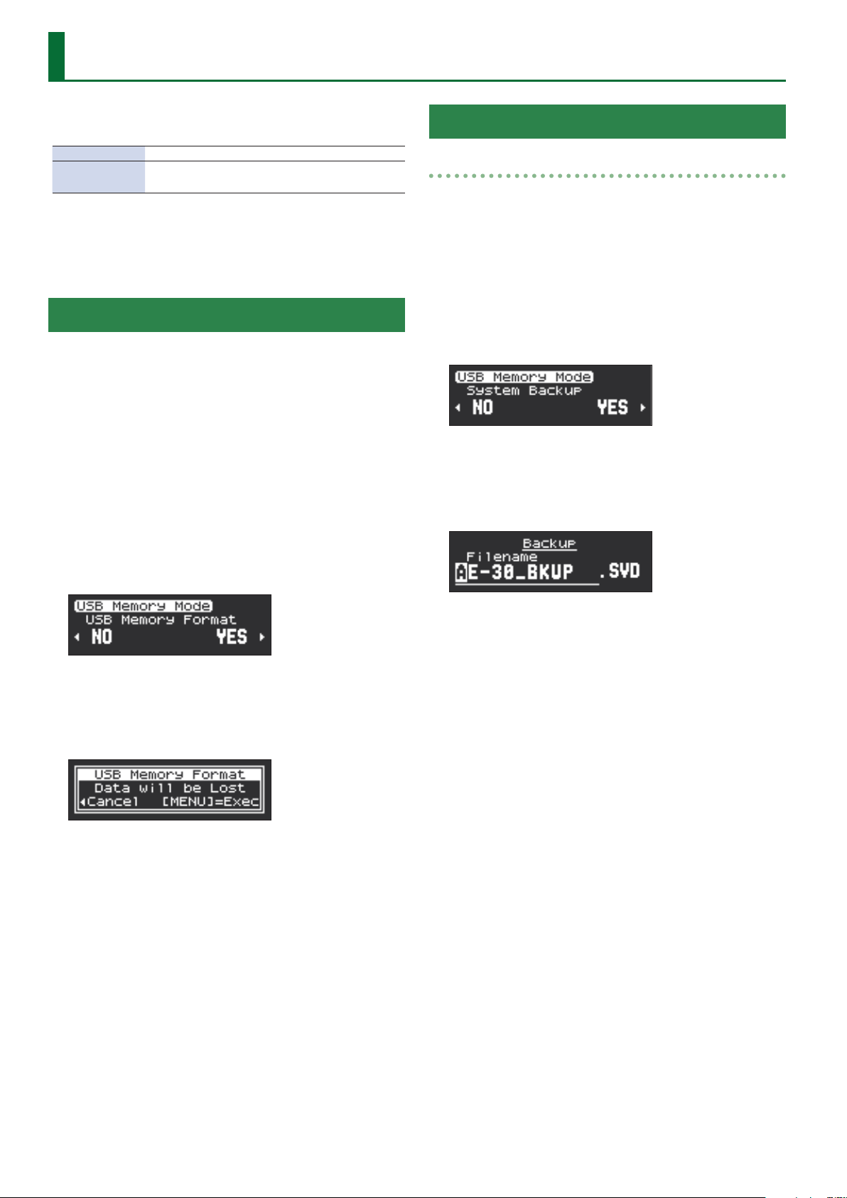
3. Press the [â] button to select “USB Memory Format,”
and press the [MENU] button.
Backup
1. Hold down [MENU] button and turn on the power.
Continue to hold down the [MENU] button until the Roland logo
disappears.
2. Connect the USB ash drive to the USB port on the
unit.
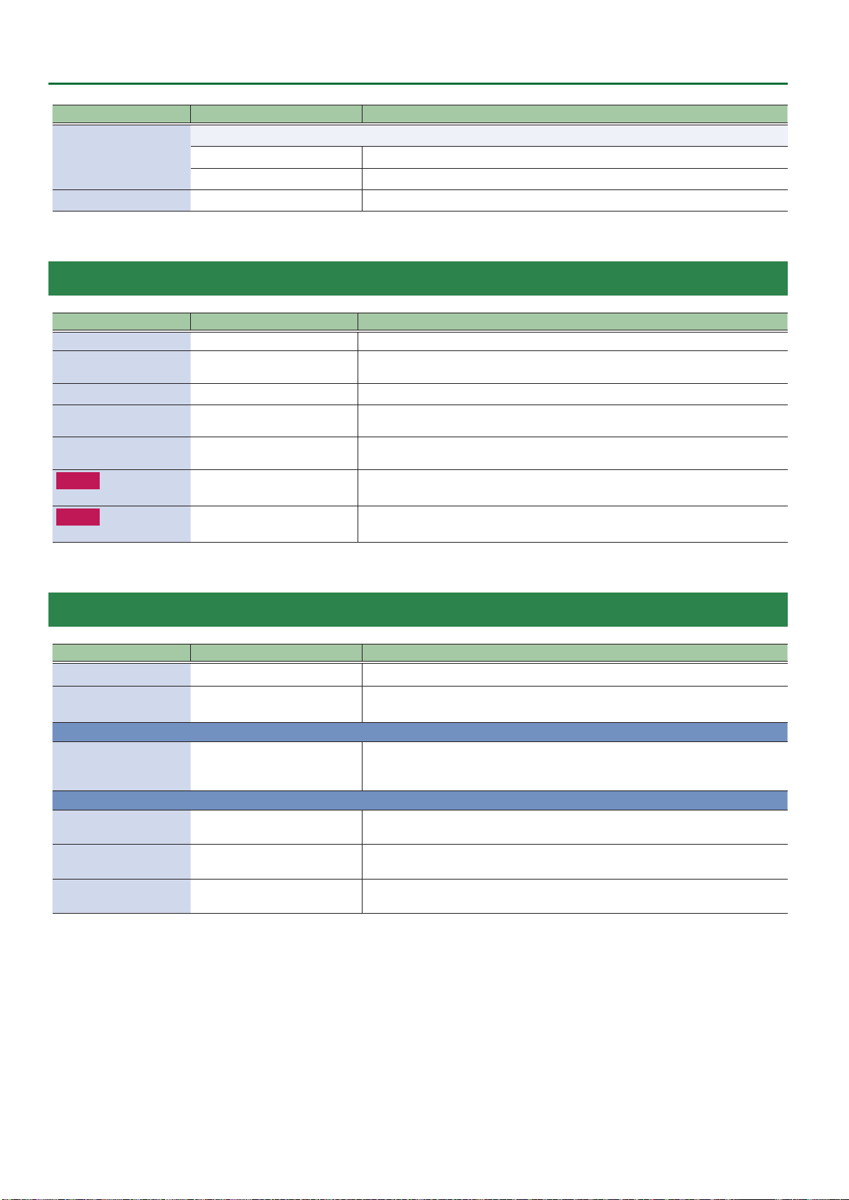
3. Press the [ã] [â] buttons to select “System Backup,”
and press the [MENU] button.
4. Press the [â] button to select “YES.” If you decide to
cancel, press the [ã] button to select “NO.”
5. Enter the le name.
4. To execute formatting, press the [â] button to select
“YES.” If you decide to cancel, press the [ã] button to
select “NO.”
Selecting “YES” displays a conrmation screen.
5. Press the [MENU] button.
“Executing...” is displayed on the screen and the USB ash drive is
formatted. When formatting is nished, “Complete” appears and
then the display returns to the USB Memory Format screen.
6. Turn o the power and disconnect the USB ash
drive.
Press the [ã] [â] buttons to move the cursor, then press [à] [á]
buttons to input the characters. Use [S1] button to insert one
character and [S2] button to delete it.
6. Press the [MENU] button.
“Write OK ?” is displayed on the screen.
7. To execute the backup operation, press the [â]
button to select “YES.” If you decide to cancel, press
the [ã] button to select “NO.”
“Writing...” is displayed on the screen and the backup operation is
executed. When the operation is nished, “Complete” appears and
then the display returns to the System Backup screen.
8. Turn o the power and disconnect the USB ash
drive.
14

Data Backup and Restore Operations
Restore
1. Hold down [MENU] button and turn on the power.
Continue to hold down the [MENU] button until the Roland logo
disappears.
2. Connect the USB ash drive containing the backed-
up data to the USB port on the unit.
3. Press the [ã] [â] buttons to select “System Restore,”
and press the [MENU] button.
4. Press the [â] button to select “YES.” If you decide to
cancel, press the [ã] button to select “NO.”
5. Press the [ã] [â] buttons to select the backed-up
le, and press the [MENU] button.
Backing Up/Restoring Scene Settings
Backup
1. Hold down [MENU] button and turn on the power.
Continue to hold down the [MENU] button until the Roland logo
disappears.
2. Connect the USB ash drive to the USB port on the
unit.
3. Press the [ã] [â] buttons to select “Scene Backup,”
and press the [MENU] button.
4. Press the [â] button to select “YES.” If you decide to
cancel, press the [ã] button to select “NO.”
5. Enter the le name.
A conrmation screen appears.
6. To execute the restore operation, press the [â]
button to select “YES.” If you decide to cancel, press
the [ã] button to select “NO.”
“Writing...” is displayed on the screen and the restore operation is
executed. When the operation is nished, “Complete” appears and
then the display returns to the System Restore screen.
* If les could not be read in correctly, “Read Error” is displayed. Verify
the connection of the USB ash drive, then carry out the restore
operation again. Also, if the backed-up data of the scene setting is
selected at “System Restore,” “Read Error” is displayed.
7. Turn o the power and disconnect the USB ash
drive.
Press the [ã] [â] buttons to move the cursor, then press [à] [á]
buttons to input the characters. Use [S1] button to insert one
character and [S2] button to delete it.
6. Press the [MENU] button.
“Write OK ?” is displayed on the screen.
7. To execute the backup operation, press the [â]
button to select “YES.” If you decide to cancel, press
the [ã] button to select “NO.”
“Writing...” is displayed on the screen and the backup operation is
executed. When the operation is nished, “Complete” appears and
then the display returns to the Scene Backup screen.
8. Turn o the power and disconnect the USB ash
drive.
15

Data Backup and Restore Operations
Restore
1. Hold down [MENU] button and turn on the power.
Continue to hold down the [MENU] button until the Roland logo
disappears.
2. Connect the USB ash drive containing the backed-
up data to the USB port on the unit.
3. Press the [ã] [â] buttons to select “Scene Restore,”
and press the [MENU] button.
4. Press the [â] button to select “YES.” If you decide to
cancel, press the [ã] button to select “NO.”
5. Press the [ã] [â] buttons to select the backed-up
le, and press the [MENU] button.
A conrmation screen appears.
6. To execute the restore operation, press the [â]
button to select “YES.” If you decide to cancel, press
the [ã] button to select “NO.”
“Writing...” is displayed on the screen and the restore operation is
executed. When the operation is nished, “Complete” appears and
then the display returns to the Scene Restore screen.
* If les could not be read in correctly, “Read Error” is displayed. Verify
the connection of the USB ash drive, then carry out the restore
operation again. Also, if the backed-up data of the system setting is
selected at “Scene Restore,” “Read Error” is displayed.
7. Turn o the power and disconnect the USB ash
drive.
16

Installing a SOUND PACK/WAVE EXPANSION
Preparing the Sound Files
* If you’re using the USB ash drive for the rst time, format it using
the Aerophone.
Ø “Formatting a USB Flash Drive” (p. 14)
1. Prepare the sound le that you will add on the
Aerophone, and place the le on your computer.
MEMO
Sound les such as SOUND PACK or WAVE EXPANSION can be
obtained via the Roland Cloud.
* Wave expansions can only be installed on the AE-30.
For more about Roland Cloud, refer to the Roland website.
Ø https://www.roland.com/
2. Connect the USB ash drive to your computer.
3. Save the le in the appropriate directory of your
USB ash drive.
SOUND PACK (extension: .SDZ): ROLAND/SOUND folder
WAVE EXPANSION (extension: .EXZ): Root directory
4. Disconnect the USB ash drive from your computer.
Importing a SOUND PACK
This is how to import a SOUND PACK to the user tone/scene.
1. While holding down the [MENU] button, turn on the
power.
Hold down the [MENU] button until the Roland logo disappears.
2. Connect the USB ash drive containing the tone le
to the USB port of this instrument.
3. Use the [ã] [â] button to select “Import Tone,” and
then press the [MENU] button.
7. Select the import destination for the tones/scenes.
Use the [à] [á] buttons to switch, use the [â] button to select, and
use the [ã] button to disregard your selection.
A [+] mark is shown on the selected tone/scene number.
8. Press the [MENU] button when you’re nished
selecting.
When importing tones
1. When “Make Scene” is displayed, generate a
scene for the tone to be imported.
2. Use the [à] [á] buttons to switch between
scenes, use the [â] button to select, and use the
[ã] button to disregard your selection.
A [+] mark is shown on the selected scene number.
3. Press the [MENU] button when you’re nished
selecting.
“Import OK?” is shown on the screen.
4. To import, press the [â] button and select “YES”; and
to cancel, press the [ã] button and select “NO.”
Selecting “YES” imports the data.
When the operation is completed, the display indicates
“Completed!”.
Press the [MENU] button to return to the Import Tone screen.
MEMO
Hold down the [MENU] button to return to the Import Tone screen.
4. Use the [â] button to select “YES.”
If you decide to cancel, press the [ã] button to select “NO.”
5. Use the [ã] [â] buttons to select the le to import,
and press the [MENU] button.
If this is the rst time to import data, a screen appears that asks you
to install the user license.
To continue importing, press the [â] button and then select “YES.”
6. Select the tones/scenes to import.
Use the [à] [á] buttons to switch between tones/scenes, use the
[â] button to select, and use the [ã] button to disregard your
selection.
A [+] mark is shown on the selected tone/scene number.
Press the [MENU] button when you’re nished selecting.
17

Installing a SOUND PACK/WAVE EXPANSION
AE-30
Installing a WAVE EXPANSION
1. While holding down the [MENU] button, turn on the
power.
Hold down the [MENU] button until the Roland logo disappears.
2. Connect the USB ash drive containing the sound
le to the USB port of this instrument.
3. Use the [ã] [â] button to select “Install Expansion,”
and then press the [MENU] button.
4. Use the [â] button to select “YES.”
If you decide to cancel, press the [ã] button to select “NO.”
5. Use the [ã] [â] buttons to select the le to install,
and press the [MENU] button.
If this is the rst time to install data, a screen appears that asks you
to install the user license.
To continue installing, press the [â] button and then select “YES.”
“Install OK?” is shown on the screen.
6. To install, press the [â] button and select “YES”; and
to cancel, press the [ã] button and select “NO.”
Selecting “YES” installs the data.
When the operation is completed, the display indicates
“Completed!”.
Press the [MENU] button to return to the Install Expansion screen.
MEMO
Hold down the [MENU] button to return to the Install Expansion
screen.
AE-30
Managing the WAVE EXPANSION Data
This shows you how to manage the WAVE EXPANSION data you’ve
installed.
1. While holding down the [MENU] button, turn on the
power.
Hold down the [MENU] button until the Roland logo disappears.
2. Use the [ã] [â] button to select “Expansion
Manager,” and then press the [MENU] button.
3. Use the [â] button to select “YES.”
If you decide to cancel, press the [ã] button to select “NO.”
4. Use the [ã] [â] buttons to select the installed WAVE
EXPANSION data, and press the [MENU] button.
5. Use the [ã] [â] buttons to select what to do with the
data you’ve selected, and press the [MENU] button.
The “Make Scene” operation creates scenes used for WAVE
EXPANSION data tones in the user region. The Tone Select screen
appears. (Go to step 6.)
The “Uninstall” operation uninstalls the WAVE EXPANSION data.
(Go to step 10.)
6. Select the tone used to create the scene data.
Use the [à] [á] buttons to switch, use the [â] button to select, and
use the [ã] button to disregard your selection.
A [+] mark is shown on the selected tone number.
7. Press the [MENU] button when you’re nished
selecting.
The Destination screen appears.
8. Select where the scene is to be created.
Use the [à] [á] buttons to switch, use the [â] button to select, and
use the [ã] button to disregard your selection.
A [+] mark is shown on the selected scene number.
Press the [MENU] button when you’re nished selecting.
“Make OK?” is shown on the screen.
18
9. To create (make), press the [â] button and select
“YES”; and to cancel, press the [ã] button and select
“NO.”
Selecting “YES” creates the scene.
When the operation is completed, the display indicates
“Completed!”.
Press the [MENU] button to return to the Expansion Manager
screen.
10. The message “Uninstall OK?” appears.
To uninstall, press the [â] button and select “YES”; and to cancel,
press the [ã] button and select “NO.”
11.
A conrmation message appears onscreen.
Press the [MENU] button to execute, or press the [ã] button to
cancel and return to the Expansion Manager screen.
MEMO
Hold down the [MENU] button to return to the Expansion Manager
screen.

Installing a SOUND PACK/WAVE EXPANSION
Initializing a User License
User License
SOUND PACK and WAVE EXPANSION are associated with the
user licenses of the user who downloaded them.
SOUND PACK or WAVE EXPANSION that have diering user
licenses cannot be imported into the same Aerophone.
User A
A
EXZ001
If you want to import or install SOUND PACK and WAVE
EXPANSION that has a dierent user license than what is already
registered to this Aerophone unit, you must initialize the user
licenses.
User A
A B
EXZ002
A
User A
A B
EXZ002
User B
EXZ002
User B
EXZ002
3. Press the [â] button and select “YES.” To cancel, press
the [ã] button and select “NO.”
4. The Remove License conrmation message appears.
Press the [MENU] button to execute.
If you decide to cancel, press the [ã] button.
When the reset is complete, the message “Completed!” appears.
Press the [MENU] button to return to the Remove License screen.
Initialize
A
Here’s how to reset a user license.
When a license is reset, the installed wave expansion is uninstalled.
1. While holding down the [MENU] button, turn on the
power.
Hold down the [MENU] button until the Roland logo disappears.
2. Use the [ã] [â] button to select “Remove License,”
and then press the [MENU] button.
19

How the Scenes are Structured
OSC
Filter
Amp
LFO 2
LFO 1
Pitch Env
Filter Env
Amp Env
Partial EQ
Partial Pan
Partial
Level
Output
Chorus
Send Level
Reverb
Send Level
Partial 2
Partial 3
Partial 4
DRY
MFX
MFX
Dry
Chorus
Reverb
MFX
Partial 1
Tone
Part 1
Part EQ
Part EQ
Part Pan
Part Pan
MFX
Part Mix
Part Chorus Send level
Part Reverb Send Level
Part Delay Send Level
Chorus
Reverb
Part Level
Output Assign
Part 2
Part 3
Part 4
IFX
IFX Chorus Send level
IFX Delay Send Level
IFX Reverb Send Level
Chorus
Chorus
Reverb Send Level
Delay
Delay
Reverb Send Level
Reveb
Tone MFX
Chorus Send Level
Scene Level
IFX Input
Direct
Chorus
Send
Delay
Send
Reverb
Send
Mix
DRY
IFX
Tone MFX
Reverb Send Level
Scene
MFX
Part 1 (Super NATURAL tone)
Part EQ
Part Pan
Part Mix
Part Chorus Send level
Part Reverb Send level
Part Delay Send Level
Part Level
Output Assign
Part 2 (ZEN-Core tone for Drone)
IFX
IFX Chorus Send Level
IFX Delay Send Level
IFX Reverb Send level
Chorus
Chorus
Reverb Send Level
Delay
Delay
Reverb Send Level
Reveb
Scene Level
IFX Input
Direct
Chorus
Send
Delay
Send
Reverb
Send
Mix
DRY
IFX
Scene
Behavior Modeling Super NATURAL sound core
SuperNATURAL tone
(Preset Only)
ZEN-Core Tone
SuperNATURAL Tone
20

Drum Kit
MFX
Part 1 (Drum Kit tone)
Part EQ
Part Pan
Part Mix
Part Chorus
Send Level
Part Reverb
Send Level
Part Delay
Send level
Part Level
Output Assign
IFX
IFX Chorus Send Level
IFX Delay Send Level
IFX Reverb Send Level
Chorus
Chorus
Reverb Send Level
Delay
Delay
Reverb Send Level
Reveb
Scene Level
IFX Input
Direct
Chorus
Send
Delay
Send
Reverb
Send
Mix
DRY
IFX
Scene
ZEN-Core Drum Kit
Chorus Send Level
Reverb Send Level
Chorus
Reverb
Drum Kit tone
(Preset Only)
How the Scenes are Structured
21

You can use the app “Aerophone Pro Editor” to congure the scene
Scene Parameters
Parameter Value Explanation
Scene Name Species the scene name (maximum of 16 characters).
parameters.
SCENE/COMMON
Parameter Value Explanation
Scene Volume 0–127 Sets the overall scene volume.
Scene Tempo 20.00–300.00 Sets the scene tempo. This is used for eects and other purposes.
Scene Transpose -5–0–+6
Scene Octave Shift -3–0–+3 Sets how many octaves the scene is shifted.
Bend Range Ctrl 0–24
Bend Range Bite Dn
Bend Range Bite Up
0, 5, 10–100, 200–2400 (cent)
AE-30 Bend Range
Motion Dn
AE-30 Bend Range
Motion Up
Harmony 1 Assign
Harmony 2 Assign
Harmony 3 Assign
Harmony 4 Assign
0–2400 (cent)
Sets the pitch of the harmony sound that works when each controller function is set to “Harmony.”
You can add up to four harmony notes.
* This is enabled when the Harmony Source system parameter is set to “Scene”(p. 5)
Oct below (-12), 7th Maj below (-11), 7th min below (-10), 6th Maj below (-9), 6th min below (-8), 5th below (-7),
Tritone below (-6), 4th below (-5), 3rd Maj below (-4), 3rd min below (-3), 2nd Maj below (-2), 2nd min below (-1),
O,
2nd min above (+1), 2nd Maj above (+2), 3rd min above (+3), 3rd Maj above (+4), 4th above (+5), Tritone above (+6),
5th above (+7), 6th min above (+8), 6th Maj above (+9), 7th min above (+10), 7th Maj above (+11), Oct above (+12)
Sets how much the scene is transposed.
* This is enabled when the Transpose Mode system parameter is “Scene” (p. 3).
Sets the bend range in semitones, when “Bend
Down” or “Bend Up” is assigned to the thumb lever or
to another controller.
Sets the bend range in cents, when “Bend Down” or
“Bend Up” is assigned to the bite controller.
Sets the bend range in cents, when “Bend Up/Down” is assigned to the motion
control.
* This is enabled when Bend Range Source is “Scene.”
* This is enabled when
the Bend Range Source
system parameter is
“Scene“ (p. 4).
SCENE/ASSIGN (INT)
* These settings are enabled when the following system parameters (p. 5) are set to “Scene.”
Asgn Src Breath
Asgn Src Bite
Asgn Src Lever
AE-30 Asgn Src Thumb Pad
AE-30 Asgn Src Motion
Asgn Src S1/S2
Asgn Src Key
Controller Explanation
Breath
Bite Down
Bite Up
Thumb Lever Down
Thumb Lever Up
AE-30 Thumb Pad
AE-30 Motion
S1, S2
X, C1–5, Tc, Ta
1–8 Assigns the settings for the breath controller.
1–4 Assigns the settings for the bite controller.
1, 2 Assigns the settings for the thumb lever.
1–4 Assigns the settings for the thumb pad.
2 Assigns the settings for the motion controller.
1, 2 Assigns the settings for the [S1] and [S2] buttons.
1, 2 Assigns the settings for the [X] key and the side keys ([C1]–[C5], [Tc] and [Ta]).
22

à Assignment settings for continuously-variable controllers
Parameter Value Explanation
Assign Function
Input Min, Max
Output Min, Max
Assign Mode
Curve
For details on the parameters, refer to “Assigning a continuously-variable controller” (p. 10).
à Assignment settings for switch-type controllers
Parameter Value Explanation
Assign Function
Release Val
Press Val
Assign Mode
Curve
For details on the parameters, refer to “Assigning a switch-type controller” (p. 13).
SCENE/CONTROL SOURCE (INT)
* This is enabled when the Contorl Source Select system parameter is “Scene.”
Scene Parameters
Parameter Value Explanation
Control Source 1–4
OFF, CC01–31, CC33–95, BEND,
AFTER TOUCH
Sets the MIDI messages to be used as tone controls.
SCENE/ASSIGN (MIDI)
* These settings are enabled when MIDI control mode is on, and when the following system parameters (p. 5) are set to “Scene.”
Asgn Src Breath
Asgn Src Bite
Asgn Src Lever
AE-30 Asgn Src Thumb Pad
AE-30 Asgn Src Motion
Asgn Src S1/S2
Asgn Src Key
Controller Explanation
Breath 1–8 Assigns the settings for MIDI control with the breath controller.
Bite Down
Bite Up
Thumb Lever Down
Thumb Lever Up
AE-30 Thumb Pad
AE-30 Motion
S1, S2 1, 2 Assigns the settings for MIDI control with the [S1] and [S2] buttons.
X, C1–5, Tc, Ta 1, 2 Assigns the settings for MIDI control with the [X] key and the side keys ([C1]–[C5], [Tc] and [Ta]).
1–4 Assigns the settings for MIDI control with the bite controller.
1, 2 Assigns the settings for MIDI control with the thumb lever.
1–4 Assigns the settings for MIDI control with the thumb pad.
2
Assigns the settings for the motion controller.
23

Scene Parameters
à Assignment settings for continuously-variable controllers
Parameter Value Explanation
Assign Function
Input Min, Max
Output Min, Max
Assign Mode
Curve
à Assignment settings for switch-type controllers
Parameter Value Explanation
Assign Function
Release Val
Press Val
Assign Mode
Curve
For details on the parameters, refer to “Assigning a continuously-variable controller” (p. 13).
For details on the parameters, refer to “Assigning a switch-type controller” (p. 13).
24

SCENE/CONTROL (MIDI)
* The following settings are enabled when MIDI control mode is on.
Parameter Value Explanation
Tx Channel
Bank MSB (CC#0)
Bank LSB (CC#32)
PC
Velocity
Volume (CC#7)
Pan (CC#10)
Modulation (CC#1)
Reverb (CC#91)
Chorus (CC#93)
Coarse (RPN#2)
Fine Tune (RPN#1)
Bend Rng (RPN#0)
Cuto (CC#74)
Resonance (CC#71)
Attack (CC#73)
Decay (CC#75)
Release (CC#72)
MONO/POLY
(CC#126/127)
1–16 Species the MIDI transmit chaunnel.
OFF, 0–127 Sets the bank select/program change message that is transmitted when a scene is
OFF, 0–127
OFF, 1–128
These parameters set the note-on velocity values for MIDI output.
REAL The velocity value is determined by the strength of your tonguing.
1–127 Transmits the specied value (a xed value).
OFF, 0–127
OFF, L64–0–63R
OFF, 0–127
OFF, -48–0–+48
OFF, -50–0–+50
OFF, 0–24
OFF, 0–127
OFF, MONO (CC#126),
POLY (CC#127)
selected.
When this is set to “OFF,” no bank select/program change is transmitted.
* These parameters are enabled when the MIDI Ctrl PC and MIDI Ctrl BS (p. 7)
system parameters are set to “On.”
Sets the value transmitted for Volume (CC#7) when a scene is selected.
When this is set to “OFF,” no bank select/program change is transmitted.
Sets the value transmitted for PAN (#CC#10) when a scene is selected.
When this is set to “OFF,” no bank select/program change is transmitted.
Sets the value transmitted for Modulation (CC#1) when a scene is selected.
When this is set to “OFF,” no bank select/program change is transmitted.
Sets the value transmitted for Reverb Send (CC#91) when a scene is selected.
When this is set to “OFF,” no bank select/program change is transmitted.
Sets the value transmitted for Chorus Send (CC#93) when a scene is selected.
When this is set to “OFF,” no bank select/program change is transmitted.
Sets the value transmitted for Coarse Tune (RPN#2) when a scene is selected.
When this is set to “OFF,” no bank select/program change is transmitted.
Sets the value transmitted for Fine Tune (RPN#1) when a scene is selected.
When this is set to “OFF,” no bank select/program change is transmitted.
Sets the value transmitted for Bend Range (RPN#0) when a scene is selected.
When this is set to “OFF,” no bank select/program change is transmitted.
Sets the value transmitted for Cuto Oset (CC#74) when a scene is selected.
When this is set to “OFF,” no bank select/program change is transmitted.
Sets the value transmitted for Resonance Oset (CC#71) when a scene is selected.
When this is set to “OFF,” no bank select/program change is transmitted.
Sets the value transmitted for Attack Time Oset (CC#73) when a scene is selected.
When this is set to “OFF,” no bank select/program change is transmitted.
Sets the value transmitted for Decay Time Oset (CC#75) when a scene is selected.
When this is set to “OFF,” no bank select/program change is transmitted.
Sets the value transmitted for Release Time Oset (CC#72) when a scene is selected.
When this is set to “OFF,” no bank select/program change is transmitted.
Sets the value transmitted for Mono/Poly (CC#126/127) when a scene is selected.
When this is set to “OFF,” no bank select/program change is transmitted.
Scene Parameters
SCENE/PART
Parameter Value Explanation
PartSW OFF, ON Turns each part (PART 1–4) on/o.
SCENE/MODE
Parameter Value Explanation
Species the part mode.
Part Mode
LEAD This is the usual mode for playing melodies and the like.
DRONE
This is a special mode for playing sustaining low notes.
This mode is used with the assign function set to “Drone Sw” (p. 12).
25

Scene Parameters
SCENE/RANGE
Parameter Value Explanation
Key Range
Key Fade Width Lower 0–127
Key Fade Width Upper 0–127
Velocity Range
Velocity Fade Width
Lower
Velocity Fade Width
Upper
X-Fade Range
X-Fade Fade Width
Lower
X-Fade Fade Width
Upper
(Lower) C-1–G9
(Upper) C-1–G9
(Lower) 1–127
(Upper) 1–127
0–127
0–127
(Lower) 0–127
(Upper) 0–127
0–127
0–127
Sets the key range for each part.
Species the upper and lower limits of the key range.
Set this when you want dierent tones to play depending on the key played.
Sets how far the range extends in which tones sound, when a key is played that’s
lower than Key Range Lower.
When no sound is to be heard for keys played outside of this range, set this to “0.”
Sets how far the range extends in which tones sound, when a key is played that’s
higher than Key Range Upper.
When no sound is to be heard for keys played outside of this range, set this to “0.”
Sets the lower/upper limits for the velocities at which tones play.
Use this to make dierent tones sound when playing at dierent velocities.
Sets the intensity at which tones sound when played softer than the Velocity
Range Lower.
When no sound is to be heard, set this to “0.”
Sets the intensity at which tones sound when played louder than the Velocity
Range Upper.
When no sound is to be heard, set this to “0.”
Sets the X-Fade (CC30) lower/upper limits within which tones play.
Set this when you want dierent tones to play according to the X-Fade (CC30)
value.
Sets how strongly the sound is played when the X-Fade (CC30) value is lower than
X-Fade Range Lower. When no sound is to be heard, set this to “0.”
Sets how strongly the sound is played when the X-Fade (CC30) value is higher than
X-Fade Range Upper. When no sound is to be heard, set this to “0.”
SCENE/PITCH
Parameter Value Explanation
Part Octave Shift -3–0–+3 Sets the pitch of the part’s sound in octaves (up to ±3 octaves).
Part Coarse Tune -48–0–+48 Shifts the pitch of the part in semitones.
Part Fine Tune -50–0–+50 cent Finely adjusts the part’s pitch in units of one cent.
SCENE/OFFSET
Parameter Value Explanation
Adjusts how wide the lter is open.
Cuto -64–0–+63
Resonance -64–0–+63
Attack Time -64–0–+63
Decay Time -64–0–+63
Release Time -64–0–+63
Vibrato Rate -64–0–+63
Increasing this value makes the sound brighter, and decreasing it makes the sound
darker.
Emphasizes the portion of the sound in the region of the cuto frequency, adding
character to the sound.
Excessively high settings can produce oscillation, causing the sound to distort.
Increasing this value strengthens the character, and decreasing it weakens the
character.
Sets the time from note-on to when the volume rises.
Larger settings of this value make the attack gentler, and smaller settings make the
attack sharper.
Sets the time over which the volume decreases from its attack level.
Larger settings of this value make the decay longer, and smaller settings make the
decay shorter.
Sets the time from note-o to when the volume fades out.
Larger settings of this value make the sound linger, and smaller settings make the
sound end more abruptly.
Adjusts the vibrato speed (the rate at which the pitch is modulated).
The pitch is modulated more rapidly for higher settings, and more slowly with
lower settings.
26

Parameter Value Explanation
This adjusts the depth of the vibrato eect (the depth at which the pitch is
Vibrato Depth -64–0–+63
Vibrato Delay -64–0–+63
modulated).
The pitch is modulated more greatly for higher settings, and less with lower
settings.
Adjusts the time until vibrato (pitch modulation) starts to apply.
Higher settings produce a longer time before vibrato begins, while lower settings
produce a shorter time.
SCENE/EQ
Parameter Value Explanation
EQ Switch OFF, ON
Input Gain -24–+24 dB Adjusts the amount of boost/cut for the input to the EQ.
Low Gain -24–+24 dB Adjusts the amount of boost/cut of the low frequency range.
Low Freq 20–16000 Hz Sets the center frequency of the low range.
Mid Gain -24–+24 dB Adjusts the amount of boost/cut of the middle frequency range.
Mid Freq 20–16000 Hz Sets the center frequency of the middle range.
Mid Q 0.5–16.0
High Gain -24–+24 dB Adjusts the boost/cut of the high frequency range.
High Freq 20–16000 Hz Sets the center frequency of the high range.
Sets whether to use the part EQ (an equalizer applied to each part) is used (ON) or
not used (OFF).
Sets the bandwidth of the middle frequency range. Higher values make the width
narrower.
Scene Parameters
SCENE/OUTPUT
Parameter Value Explanation
Part Level 0–127 Sets the volume of each part.
Part Pan L64–0–63R Sets the panning of each part’s sound when using stereo output.
Chorus Send 0–127 Species the send level to chorus.
Delay Send 0–127 Species the send level to delay.
Reverb Send 0–127 Species the send level to reverb.
Output Assign DRY, IFX Selects the output destination for each part.
SCENE/CONTROL
Parameter Value Explanation
Choose “MONO” if you want the tone assigned to the part to play monophonically;
Mono/Poly MONO, POLY, TONE
Legato Switch OFF, ON, TONE
Portamento Switch OFF, ON, TONE
Portamento Time 0–127, TONE
Unison Switch OFF, ON, TONE
choose “POLY” if you want to play it polyphonically.
Choose “TONE” if you want to use the setting specied by the tone.
Legato is enabled when Legato Switch is “ON” and Mono/Poly is set to “MONO.”
Choose “TONE” if you want to use the setting specied by the tone.
This makes the pitch change smoothly while you are playing one note and then
play legato by ngering another key.
Select “ON” to apply portamento, or “OFF” if you don’t want to apply portamento.
Choose “TONE” if you want to use the setting specied by the tone.
When portamento is used, this species the time over which the pitch changes.
A higher value increases the time it takes for one pitch to slide to the next.
Choose “TONE” if you want to use the setting specied by the tone.
This layers a single tone.
Choose “ON” if you want to use unison, or “OFF” if you don’t.
Choose “TONE” if you want to use the setting specied by the tone.
* Parts whose Unison Switch is “ON” play in mono.
27
Scene Parameters
Parameter Value Explanation
These parameters set the note-on velocity values.
Velocity
Fixed Velocity 1–127 This sets the velocity value used for the “FIXED” velocity setting.
REAL The velocity value is determined by the strength of your tonguing.
FIXED The specied value (a xed value) is used.
SCENE/CONTROL RX
Parameter Value Explanation
Rx S1, Rx S2 OFF, ON Sets whether to receive [S1] and [S2] button operations (ON) or not (OFF).
Rx X, Rx C1–5, Rx Tc,
Rx Ta
Rx Breath OFF, ON Sets whether to receive breath controller operations (ON) or not (OFF).
Rx Bite Down
Rx Bite Up
Rx Thumb Lever Down
Rx Thumb Lever Up
AE-30
Rx Thumb Pad
AE-30
Rx Motion
OFF, ON Sets whether to receive side key button operations (ON) or not (OFF).
OFF, ON Sets whether to receive bite controller operations (ON) or not (OFF).
OFF, ON Sets whether to receive thumb lever operations (ON) or not (OFF).
OFF, ON Sets whether to receive thumb pad operations (ON) or not (OFF).
OFF, ON Sets whether to receive motion controller operations (ON) or not (OFF).
SCENE/IFX
Parameter Value Explanation
IFX SW OFF, ON Switches the IFX on/o.
IFX Type
FX
IFX parameters
SEND
Chorus Send Level 0–127
Reverb Send Level 0–127
Delay Send Level 0–127
See “MFX/IFX Parameters”
(p. 51)
See “MFX/IFX Parameters”
(p. 51)
Selects the IFX type.
Congure the parameters for the selected IFX.
The available parameters dier depending on the type of the eects you selected
in IFX Type.
Sets the amount of chorus.
If you don’t want to add the chorus eect, set it to 0.
Sets the amount of reverb.
If you don’t want to add the reverb eect, set it to 0.
Sets the amount of delay.
If you don’t want to add the delay eect, set it to 0.
28

SCENE/CHORUS
Parameter Value Explanation
CH SW OFF, ON Turns the chorus on/o.
Chorus Type
FX
Chorus parameters
OUTPUT
Chorus Level 0–127
Reverb Send Level 0–127
Chorus Parameters
Selects the chorus type.
OFF, 1 Chorus, 2 CE-1, 3 SDD-320, 4 JUNO-106 Chorus
Congure the parameters of the selected chorus type.
See “Chorus parameters”
The available parameters dier depending on the type of chorus you selected in
Chorus Type.
Sets the amount of chorus.
If you don’t want to add the chorus eect, set it to 0.
Sets the amount of reverb.
If you don’t want to add the reverb eect, set it to 0.
Scene Parameters
1 Chorus
This is a stereo chorus.
Parameter Value Explanation
Rate 0–127 Frequency of modulation
Depth 0–127 Depth of modulation
Feedback 0–127
Level at which chorus sound is
returned to the input
2 CE-1 (Chorus)
This models the classic BOSS CE-1 chorus eect unit. It provides a
chorus sound with a distinctively analog warmth.
Parameter Value Explanation
Intensity 0–127 Chorus depth
3 SDD-320 (Dimension D)
4 JUNO-106 Chorus
This models the chorus eects of the Roland JUNO-106.
Parameter Value Explanation
Mode
Noise Level 0–127
I, II, I+II, JX I,
JX II
Type of Chorus
I+II: The state when two buttons
are pressed simultaneously.
Amount of noise produced by
the chorus
This models Roland’s DIMENSION D (SDD-320). It provides a clear
chorus sound.
Parameter Value Explanation
Mode
1, 2, 3, 4, 1+4,
2+4, 3+4
Switches the mode.
29

Scene Parameters
SCENE/DELAY
Parameter Value Explanation
DLY SW
Delay Type
FX
Delay parameters
OUTPUT
Delay Level
Reverb Send Level
Delay Parameters
OFF, ON Switches the delay on/o.
Selects the types of delay.
OFF, 1 Delay, 2 T-Ctrl Dly, 3 Delay Ó Trem, 4 2Tap PanDly, 5 3Tap PanDly
Congure the parameters of the selected delay type.
See “Delay parameters”
0–127
0–127
The available parameters dier depending on the type of delay you selected in
Delay Type.
Sets the amount of delay.
If you don’t want to add the delay eect, set it to 0.
Sets the amount of reverb.
If you don’t want to add the reverb eect, set it to 0.
1 Delay
This is a stereo delay.
Parameter Value Explanation
Delay Time
(sync sw)
Delay Time
(msec)
Delay Time
(note)
Feedback -98–+98 (%)
HF Damp (*2)
OFF, ON
1–1300
Note (*1)
If this is “ON,” the delay
synchronizes with the tempo.
Adjusts the delay time from
the direct sound until the delay
sound is heard.
Adjusts the proportion of the
delay sound that is fed back into
the eect. Negative (-) settings
will invert the phase.
Adjusts the frequency above
which the delay sound fed
back to the eect is ltered out
(BYPASS: no cut).
2 T-Ctrl Dly (Time Control Delay)
A stereo delay in which the delay time can be varied smoothly.
Parameter Value Explanation
Delay Time
(sync sw)
Delay Time
(msec)
Delay Time
(note)
Acceleration 0–15
Feedback -98–+98 (%)
HF Damp (*2)
OFF, ON
1–1300
Note (*1)
If this is “ON,” the delay
synchronizes with the tempo.
Adjusts the delay time from
the direct sound until the delay
sound is heard.
When you change the delay time,
this species the time over which
the current delay time changes to
the specied delay time.
This aects the speed of pitch
change as well as the delay time.
Adjusts the proportion of the
delay sound that is fed back into
the eect. Negative (-) settings
will invert the phase.
Adjusts the frequency above
which the delay sound fed
back to the eect is ltered out
(BYPASS: no cut).
30

Scene Parameters
3 DelayÓTrem (DelayÓTremolo)
Tremolo is applied to the delay sound.
Parameter Value Explanation
Input Mode
Delay Time
(sync sw)
Delay Time
(msec)
Delay Time
(note)
Feedback -98–+98 (%)
HF Damp (*2)
Tremolo Switch OFF, ON Switches the tremolo eect on/o
Tremolo Mod
Wave
Tremolo Rate
(sync sw)
Tremolo Rate
(Hz)
Tremolo Rate
(note)
Tremolo Depth 0–127 Tremolo depth
MONAURAL The input is mono-mixed.
STEREO The sound is input in stereo.
OFF, ON
1–1300
Note (*1)
Modulation Wave
TRI Triangle wave
SQR Square wave
SIN Sine wave
SAW1
SAW2
TRP Trapezoidal wave
OFF, ON
0.05–10.00 (Hz)
Note (*1)
If this is “ON,” the delay
synchronizes with the tempo.
Adjusts the delay time from
the direct sound until the delay
sound is heard.
Adjusts the proportion of the
delay sound that is fed back into
the eect. Negative (-) settings
will invert the phase.
Adjusts the frequency above
which the delay sound fed
back to the eect is ltered out
(BYPASS: no cut).
Sawtooth wave
If this is “ON,” the tremolo
synchronizes with the tempo.
Tremolo rate
5 3Tap PanDly (3 Tap Pan Delay)
Delayed sound is heard from the three locations you specify.
Parameter Value Explanation
Delay Time
(sync sw)
Delay Time
(msec)
Delay Time
(note)
Feedback -98–+98 (%)
HF Damp (*2)
Delay 1 Pan L64–63R Stereo location of Delay 1
Delay 2 Pan L64–63R Stereo location of Delay 2
Delay 3 Pan L64–63R Stereo location of Delay 3
Delay 1 Level 0–127 Volume of Delay 1
Delay 2 Level 0–127 Volume of Delay 2
Delay 3 Level 0–127 Volume of Delay 3
(*1) 1/64T, 1/64, 1/32T, 1/32, 1/16T, 1/32., 1/16, 1/8T, 1/16., 1/8, 1/4T,
1/8., 1/4, 1/2T, 1/4., 1/2, 1T, 1/2., 1, 2T, 1., 2
(*2) 200, 250, 315, 400, 500, 630, 800, 1000, 1250, 1600, 2000, 2500,
3150, 4000, 5000, 6300, 8000 (Hz), BYPASS
OFF, ON
1–2600
Note (*1)
If this is “ON,” the delay
synchronizes with the tempo.
Adjusts the delay time from the
direct sound until the third delay
sound is heard.
Adjusts the proportion of the
delay sound that is fed back into
the eect. Negative (-) settings
will invert the phase.
Adjusts the frequency above
which the delay sound fed
back to the eect is ltered out
(BYPASS: no cut).
4 2Tap PanDly (2 Tap Pan Delay)
Delayed sound is heard from the two locations you specify.
Parameter Value Explanation
Delay Time
(sync sw)
Delay Time
(msec)
Delay Time
(note)
Feedback -98–+98 (%)
HF Damp (*2)
Delay 1 Pan L64–63R Stereo location of Delay 1
Delay 2 Pan L64–63R Stereo location of Delay 2
Delay 1 Level 0–127 Volume of Delay 1
Delay 2 Level 0–127 Volume of Delay 2
OFF, ON
1–1300
Note (*1)
If this is “ON,” the delay
synchronizes with the tempo.
Adjusts the delay time from the
direct sound until the second
delay sound is heard.
Adjusts the proportion of the
delay sound that is fed back into
the eect. Negative (-) settings
will invert the phase.
Adjusts the frequency above
which the delay sound fed
back to the eect is ltered out
(BYPASS: no cut).
31

Scene Parameters
SCENE/REVERB
Parameter Value Explanation
RV SW
Reverb Type
FX
Reverb parameters
OUTPUT
Reverb Level
Reverb Parameters
OFF, ON Switches the reverb on/o.
Selects the types of reverb.
OFF, 1 INTEGRA7Rev, 2 Warm Hall, 3 Hall, 4 GS Reverb, 5 SRV-2000, 6 SRV-2000NL, 7 GM2 Reverb
Congure the parameters of the selected reverb type.
See “Reverb parameters”
0–127
The available parameters dier depending on the type of reverb you selected in
Reverb Type.
Sets the amount of reverb.
If you don’t want to add the reverb eect, set it to 0.
1 INTEGRA7Rev (INTEGRA 7 Reverb)
Parameter Value Explanation
Char
PreDelay 0–100
Time 0.1–10.0 (sec)
Density 0–127
Diusion 0–127
LF Damp 0–100
HF Damp 0–100
Spread 0–127 Reverb spread
Tone 0–127 Tonal character of the reverb
ROOM1–2,
HALL1–2,
PLATE
Type of reverb
Adjusts the delay time from the
direct sound until the reverb
sound is heard.
Adjusts the decay length of the
reverb sound.
Adjusts the density of the reverb
sound.
Adjusts the change in the density
of the reverb over time.
The higher the value, the more
the density increases with time.
(The eect of this setting is most
pronounced with long reverb
times.)
Adjusts the low-frequency
portion of the reverb.
Adjusts the high-frequency
portion of the reverb.
2 Warm Hall
Parameter Value Explanation
PreDelay 0–100
Time 0.3–30.0 (sec)
Pre LPF (*3)
Pre HPF (*4)
PreLoop LPF (*3)
Diusion 0–127
HF Damp Freq (*5)
HF Damp Ratio 0.1–1.0
(*1) 16, 20, 25, 32, 40, 50, 63, 80, 100, 125, 160, 200, 250, 315, 400, 500,
630, 800, 1000, 1250, 1600, 2000, 2500, 3150, 4000, 5000, 6300,
8000, 10000, 12500, 15000 (Hz), BYPASS
(*2) BYPASS, 16, 20, 25, 32, 40, 50, 63, 80, 100, 125, 160, 200, 250, 315,
400, 500, 630, 800, 1000, 1250, 1600, 2000, 2500, 3150, 4000,
5000, 6300, 8000, 10000, 12500, 15000 (Hz)
(*3) 1000, 1250, 1600, 2000, 2500, 3150, 4000, 5000, 6300, 8000 (Hz)
Adjusts the delay time from the
direct sound until the reverb
sound is heard.
Adjusts the decay length of the
reverb sound.
Frequency above which to cut
the high-frequency portion of
the sound entering the reverb
Frequency below which to cut
the low-frequency portion of the
sound entering the reverb
Frequency above which to cut
the high-frequency portion of
the extended reverberation
Adjusts the change in the density
of the reverb over time.
Adjusts the frequency above
which to cut the high-frequency
portion of the reverb.
Adjusts the amount by which to
attenuate the high-frequency
portion of the reverb.
32

Scene Parameters
3 Hall
Parameter Value Explanation
PreDelay 0–100
Time 0–127
Size 1–8 Size of room/hall
High Cut (*6)
Density 0–127
Diusion 0–127
LF Damp Freq (*7)
LF Damp Gain -36–0 (dB)
HF Damp Freq (*8)
HF Damp Gain -36–0 (dB)
(*4) 160, 200, 250, 320, 400, 500, 640, 800, 1000, 1250, 1600, 2000,
2500, 3200, 4000, 5000, 6400, 8000, 10000, 12500 (Hz), BYPASS
(*5) 50, 64, 80, 100, 125, 160, 200, 250, 320, 400, 500, 640, 800, 1000,
1250, 1600, 2000, 2500, 3200, 4000 (Hz)
(*6) 4000, 5000, 6400, 8000, 10000, 12500 (Hz)
Adjusts the delay time from the
direct sound until the reverb
sound is heard.
Adjusts the decay length of the
reverb sound.
Adjusts the frequency above
which the high-frequency
portion of the nal output sound
is cut (BYPASS: no cut)
Adjusts the density of the reverb
sound.
Adjusts how reverb density
increases over time. (This eect
is especially noticeable with long
reverb times.)
Adjusts the frequency below
which the low-frequency portion
of the reverb sound is cut.
LF damp attenuation amount
(0: no eect)
Adjusts the frequency above
which the high-frequency
portion of the reverb sound is
cut.
HF damp attenuation amount
(0: no eect)
4 GS Reverb
5 SRV-2000
Parameter Value Explanation
R0.3, R1.0, R7.0,
R15, R22, R26,
Selection
PreDelay 0–160
Time 0.1–99.0 (sec)
HF Damp 0.05–1.00
Density 0–9
Attack Gain 0–9
Attack Time 0–9
ER Density 0–9
ER Level 0–99
EQ Low Freq 0.04–1.00 (kHz) Frequency of the low range.
EQ Low Gain -24–+12 (dB) Gain of the low range.
EQ Mid Freq 0.25–9.99 (kHz) Frequency of the middle range.
EQ Mid Gain -24–+12 (dB) Gain of the middle range.
EQ Mid Q 0.2–9.0
EQ Hi Freq 0.80–9.99 (kHz) Frequency of the high range.
EQ Hi Gain -24–+12 (dB) Gain of the high range
EQ Hi Q 0.2–9.0
R32, R37, H15,
H22, H26, H32,
H37, P-B, P-A
Selects the type of reverb oered
by the Roland SRV-2000 digital
reverb.
Adjusts the delay time from the
direct sound until the reverb
sound is heard.
Adjusts the decay length of the
reverb sound.
Adjusts the high-frequency
portion of the reverb.
Adjusts the density of the late
reverberation.
Adjusts the gain of the early
reections.
Adjusts the time of the early
reections.
Adjusts the density of the early
reections.
Adjusts the volume of the early
reections.
Width of the middle range.
Set a higher value to narrow the
range to be aected.
Species the width of the highfrequency range.
Set a higher value to narrow the
range to be aected.
Parameter Value Explanation
ROOM1–3,
HALL1–2,
Character
Pre LPF 0–7
Time 0–127
Delay
Feedback
PLATE,
DELAY,
PAN-DELAY
0–127
Selects the type of reverb.
Adjusts the amount of highfrequency attenuation for the
sound being input to the reverb.
Adjusts the decay length of the
reverb sound.
Adjusts the level at which the
reverb sound is returned to the
input.
33

Scene Parameters
6 SRV-2000NL (NON-LINEAR)
Parameter Value Explanation
PreDelay 0–120
ReverbTime -0.9–99.0 (sec)
GateTime 10–450
EQ Low Freq 0.04–1.00 (kHz) Frequency of the low range.
EQ Low Gain -24–+12 (dB) Gain of the low range.
EQ Mid Freq 0.25–9.99 (kHz) Frequency of the middle range.
EQ Mid Gain -24–+12 (dB) Gain of the middle range.
EQ Mid Q 0.2–9.0
EQ Hi Freq 0.80–9.99 (kHz) Frequency of the high range.
EQ Hi Gain -24–+12 (dB) Gain of the high range
EQ Hi Q 0.2–9.0
Adjusts the delay time from the
direct sound until the reverb
sound is heard.
Adjusts the decay length of the
reverb sound.
Adjusts the time from when the
reverb starts being heard until
the reverb sound is cut o.
Width of the middle range.
Set a higher value to narrow the
range to be aected.
Species the width of the highfrequency range.
Set a higher value to narrow the
range to be aected.
7 GM2 Reverb
Parameter Value Explanation
SMALL ROOM,
MEDIUM ROOM,
Character
Time 0–127
LARGE ROOM,
MEDIUM HALL,
LARGE HALL,
PLATE
Selects the type of reverb.
Adjusts the decay length of the
reverb sound.
34
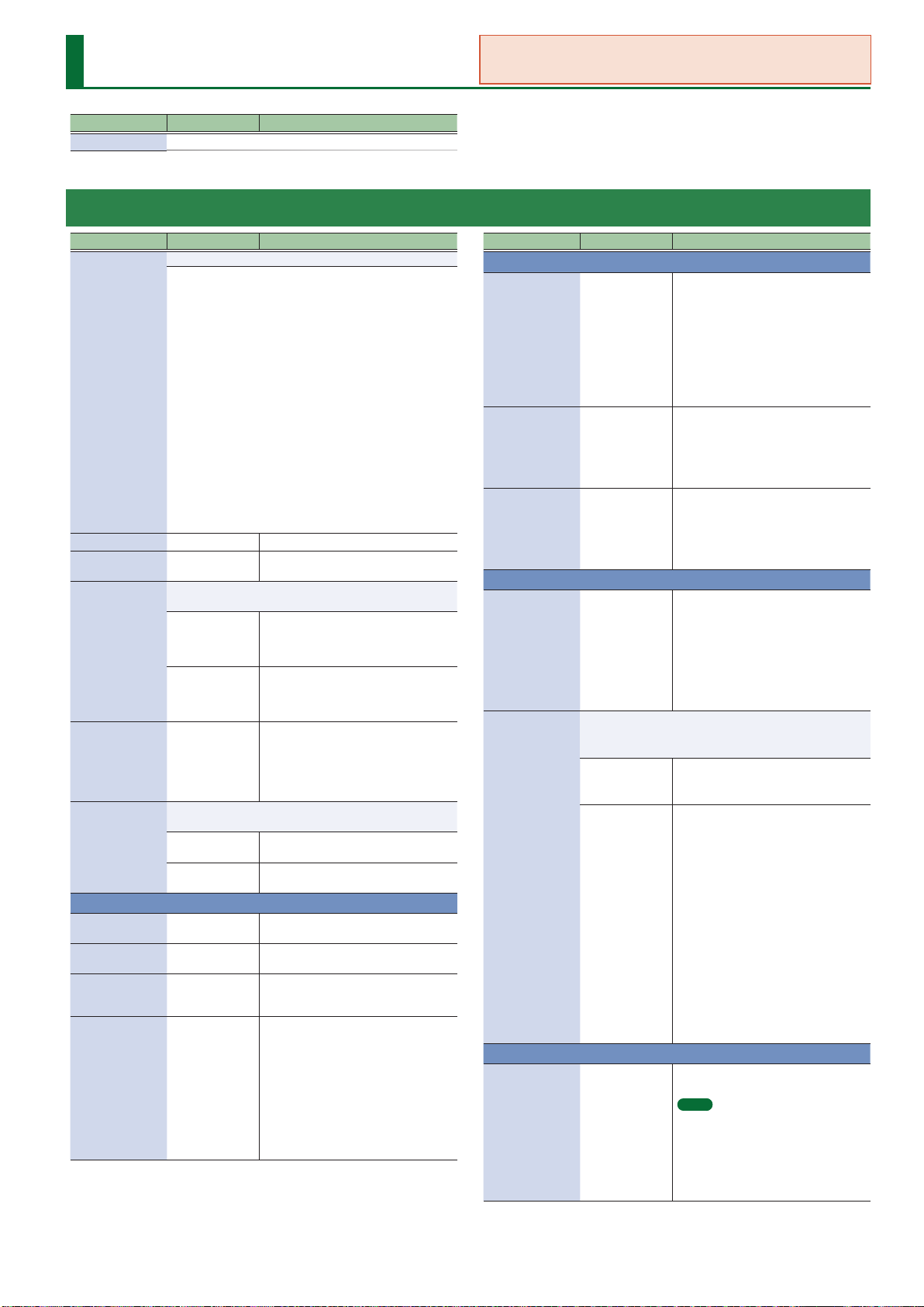
Tone Parameters
Parameter Value Explanation
Tone Name Species the tone name (maximum of 16 characters).
TONE/COMMON
You can use the app “Aerophone Pro Editor” to congure the tone parameters.
Parameter Value Explanation
Selects the tone’s category.
No Assign
Ac.Piano
Pop Piano
E.Grand Piano
E.Piano1
E.Piano2
E.Organ
Pipe Organ
Category
Tone Level 0–127
Tone Pan L64–0–63R
Priority
Analog Feel 0–127
Mono/Poly
Reed Organ
Harpsichord
Clav
Celesta
Accordion
Harmonica
Bell
Mallet
Ac.Guitar
E.Guitar
Dist.Guitar
This determines how notes will be managed when the
maximum polyphony is exceeded.
LAST
LOUDEST
Species whether the tone will play polyphonically (POLY) or
monophonically (MONO).
MONO
POLY
Ac.Bass
E.Bass
Synth Bass
Plucked/Stroke
Solo Strings
Ensemble Strs
Orchestral
Solo Brass
Ensemble Brass
Wind
Flute
Sax
Recorder
Vox/Choir
Scat
Synth Lead
Synth Brass
Synth Pad/Str
Synth Bellpad
Adjusts the overall volume of the tone.
Species the pan of the tone. “L64” is far
left, “0” is center, and “63R” is far right.
The last-played voices will be given
priority, and currently sounding notes will
be turned o in order, beginning with the
rst-played note.
The voices with the loudest volume will
be given priority, and currently sounding
notes will be turned o, beginning with
the lowest-volume voice.
Applies time-varying change to the pitch
and volume of the tone that is producing
sound, adding a sense of variability.
As you increase this value toward the
maximum, the variability becomes
greater, producing instability.
Sound only the last-played key one at
a time.
Two or more notes can be played
simultaneously.
PITCH
Coarse Tune
Fine Tune -50–+50 (cent)
Octave Shift -3–+3
Stretch Tune
Depth
-48–+48
(semitone)
OFF, 1–3
Adjusts the pitch of the sound up or
down in semitone steps (±4 octaves).
Adjusts the pitch of the sound up or
down in 1-cent steps (±50 cents).
Adjusts the pitch of the tone’s sound
up or down in units of an octave
(±3 octaves).
This setting allows you to apply “stretched
tuning” to the tone. (Stretched tuning is
a system by which acoustic pianos are
normally tuned, causing the lower range
to be lower and the higher range to be
higher than the mathematical tuning
ratios would otherwise dictate.)
With a setting of “OFF,” the tone’s tuning
will be equal temperament. A setting of
“3” will produce the greatest dierence in
the pitch of the low and high ranges.
Synth PolyKey
Synth FX
Synth Seq/Pop
Phrase
Pulsating
Beat&Groove
Hit
Sound FX
Drums
Percussion
Stack
Zone
Parameter Value Explanation
UNISON
This layers a single sound.
If the Unison Switch is “ON,” the number
of notes layered on one key will change
according to the number of keys you play.
Unison Switch OFF, ON
Size 2–8
Detune 0–100
¹ If the OSC Type (p. 40) is “PCM,” this is
limited to mono playing.
¹ If the Legato Switch is “ON,” the Delay
Time is ignored while playing legato.
¹ Even if Legato Retrigger Interval is
specied, it operates as o.
If Unison Switch is “ON,” this species the
number of notes that are assigned to
each key that is pressed.
Increasing the Unison Size increases the
polyphony, making it more likely that
notes will be cut o.
Detunes each of the notes that are
allocated by the Unison Size number,
producing a detuned eect.
As you increase this value, each note
is detuned more greatly, producing a
thicker sound.
LEGATO
Use this to make the pitch change
smoothly while you are playing one note
and then change your ngering to play a
Legato Switch OFF, ON
When Legato Switch is enabled and you play legato, this
species whether retriggering occurs (0–12) or does not occur
(OFF).
OFF
Retrigger Interval
0–12
dierent note (playing legato).
The way in which the change occurs
depends on the Legato Retrigger Interval.
* This is valid when MONO/POLY is set to
“MONO” and Legato Switch is turned
“ON.”
Only the pitch of the currently-sounding
tones changes according to the pitch of
the key.
Retriggering occurs smoothly when
the pitch dierence during legato
performance exceeds the specied value.
For example, if this is set to 4, and using
C4 as the reference pitch, playing notes
Db4–E4 legato will change only the pitch
without retriggering, but playing the F4
note (which is ve semitones away from
C4) legato will retrigger F4.
When F4 is retriggered at this time, F4
now becomes the reference pitch.
If this is set to “0,” each note is retriggered
every time regardless of the pitch
dierence.
For acoustic-type sounds in particular, an
unnatural impression can occur if only
the pitch is changed, so you’ll need to
adjust the Legato Retrigger Interval.
PORTAMENTO
Species whether the portamento eect
will be applied (ON) or not applied (OFF).
MEMO
Portamento
Switch
OFF, ON
Portamento is an eect which smoothly
changes the pitch from the rst-played
key to the next-played key. By applying
portamento when MONO/POLY is
set to “MONO,” you can simulate slide
performance techniques on a violin or
similar instrument.
35

Tone Parameters
C5
D4
C4
press D4 key
Pitch
Time
press C4 key
press C5 key
C5
D4
C4
press D4 key
Pitch
Time
press C4 key
press C5 key
Parameter Value Explanation
Species the performance conditions for which portamento
will be applied.
NORMAL Portamento will always be applied.
Mode
LEGATO
Species the type of portamento eect.
Type
RAT E
TIME The time it takes will be constant.
When another key is pressed during a pitch change produced
by portamento, a new pitch change will begin. This setting
species the pitch at which the change will begin.
Pitch
Start
NOTE
Time 0–1023
Species the pitch change curve for portamento.
LIN Change on a linear curve.
Curve Type
EXP-L
EXP-H
BEND
* These ZEN-Core tone parameters are not used in Aerophone.
Range Up 0–48 (semitone)
Range Down 0–48 (semitone)
Range Fine Up 0–100 (cent)
Range Fine Down 0–100 (cent)
Applies portamento only when you play
legato (while you are playing one note
and then change your ngering to play
another note).
The time it takes will depend on the
distance between the two pitches.
Starts a new portamento when another
key is pressed while the pitch is changing.
Portamento will begin from the pitch
where the current change would end.
When portamento is used, this species
the time over which the pitch will change.
Higher settings will cause the pitch
change to the next note to take more
time.
Change on a non-linear curve
(gentle slope).
Change on a non-linear curve
(steep slope).
Species the degree of pitch change in
semitones when the Pitch Bend lever is all
the way right.
For example, if this parameter is set to
“48,” the pitch will rise four octave when
the pitch bend lever is moved to the
right-most position.
Species the degree of pitch change in
semitones when the Pitch Bend lever is all
the way left.
For example if this is set to “48” and you
move the pitch bend lever all the way to
the left, the pitch will fall 4 octaves.
Finely adjusts the degree of pitch change
in one-cent units when the Pitch Bend
lever is moved to the right.
Finely adjusts the degree of pitch change
in one-cent units when the Pitch Bend
lever is moved to the left.
Parameter Value Explanation
Species the bend mode.
NORMAL
The pitch bend lever works in the
conventional way.
The pitch bend eect applies only to the
Bend Mode
CATCH+LAST
last-played note.
If a note-on occurs while pitch bend is
already applied, the new note sounds at
the center pitch.
The pitch starts changing only after the
controller passes through the center
position.
SOFT PEDAL
Species the amount of volume change
that occurs when you operate the soft
Soft Level Sens 0–100
pedal (CC#67).
This is eective when specied for piano
sounds.
PARTIAL MIX TABLE
Sets how the partials sound when dierent partials are used
according to how hard you initially blow (the velocity).
OFF O
Dierent partials are sounded according
ON
to the playing velocity and the Velocity
Range Lower/Upper and Velocity Fade
Low/Up (p. 41) settings.
Each partial is sounded randomly or
cyclically.
Each partial is sounded randomly or
cyclically.
Velocity Control
RANDOM
CYCLE
In the case of “RANDOM” or “CYCLE”
¹ When Structure 1-2 (3-4) has a setting other than “OFF,”
partials 1 and 2 (3 and 4) are sounded as a pair, either
randomly or in alternation.
¹ Velocity has no eect, but you’ll need to make settings for
each partial so that the Velocity Range (p. 41) does not
conict.
These parameters set the curve for the change in level when
using Velocity Control to produce dierent sounds.
When using Velocity Control between
Level Curve
EXP
partials, the crossfade level changes in a
non-linear curve.
When using Velocity Control to switch
LINEAR
between partials, the crossfade level
changes in a linear curve.
CONDITION
Adjusts the slight pitch drift that occurs
Pitch Drift 0–255
Condition 0–100
when notes are played on an analog
synthesizer.
Use this to adjust the amount of drift.
Simulates the changes that occur as a
unit ages.
36

TONE/STRUCTURE
Tone Parameters
Structure lets you sound two partials as a set.
You can create a wide range of sounds by using partial 2 or 4 (the modulator)
to modulate partial 1 or 3 (the carrier).
Since the Structure uses two partials as a pair, it provides parameters that
are used in common by the carrier and modulator.
For the following parameters, only the partial settings of the carrier are
valid (the settings of the modulator are ignored).
TONE/PARTIAL/RANGE
¹ Key Range Lower
¹ Key Range Upper
¹ Key Fade Lower
¹ Key Fade Upper
¹ Velocity Range Lower
¹ Velocity Range Upper
¹ Velocity Fade Low
¹ Velocity Fade Up
TONE/PARTIAL
¹ Partial Switch
TONE/PARTIAL/OSC
¹ Delay Mode
¹ Delay Time Sync
¹ Delay Time (note)
¹ Delay Time
TONE/PARTIAL/CONTROL
¹ Envelope Mode
¹ Receive Hold-1
¹ Redamper Switch
¹ Damper Free Note
TONE/PARTIAL/MATRIX CONTROL
¹ Destination: PMT
¹ Destination: CROSS-MOD
Parameter Value Explanation
The sound of partial 1 is modulated by partial 2.
OFF O
Implements the oscillator sync function
that is provided by an analog synthesizer.
SYNC
Structure1-2
Structure3-4
Partial Phase Lock OFF, ON
RING
XMOD, XMOD2
The sound of partial 3 is modulated by partial 4.
OFF O
SYNC
RING
XMOD, XMOD2
The partial 1 oscillator is reset at intervals
of partial 2’s pitch cycle.
* This is valid when the OSC Type
(p. 40) is “VA” or “PCM-Sync.”
Implements the ring modulator function
that is provided by an analog synthesizer.
The output sound of partial 2 is multiplied
with partial 1.
Implements the cross modulation
function that is provided by an analog
synthesizer.
The output sound of partial 2 is applied
as the pitch of partial 1.
XMOD2 is available only when Partial 1
and 3 are OSC Type (p. 40) “VA.”
Implements the oscillator sync function
that is provided by an analog synthesizer.
The partial 3 oscillator is reset at intervals
of partial 4’s pitch cycle.
* This is valid when the OSC Type
(p. 40) is “VA” or “PCM-Sync.”
Implements the ring modulator function
that is provided by an analog synthesizer.
The output sound of partial 4 is
multiplied with partial 3.
Implements the cross modulation
function that is provided by an analog
synthesizer.
The output sound of partial 4 is applied
as the pitch of partial 3.
XMOD2 is available only when Partial 1
and 3 are OSC Type (p. 40) “VA.”
It locks the waveform phase between
partials.
It is eective to use this with XMOD2.
* This is valid when the OSC Type
(p. 40) is “VA.”
RING
1-2 Level 0–127 RING level when Structure1-2 is “RING.”
3-4 Level 0–127 RING level when Structure3-4 is “RING.”
OSC1 Level 0–127
OSC2 Level 0–127
OSC3 Level 0–127
OSC4 Level 0–127
Sets the partial 1 OSC level.
* This is valid when the Structure1-2 is
“RING.”
Sets the partial 2 OSC level.
* This is valid when the Structure1-2 is
“RING.”
Sets the partial 3 OSC level.
* This is valid when the Structure3-4 is
“RING.”
Sets the partial 4 OSC level.
* This is valid when the Structure3-4 is
“RING.”
37
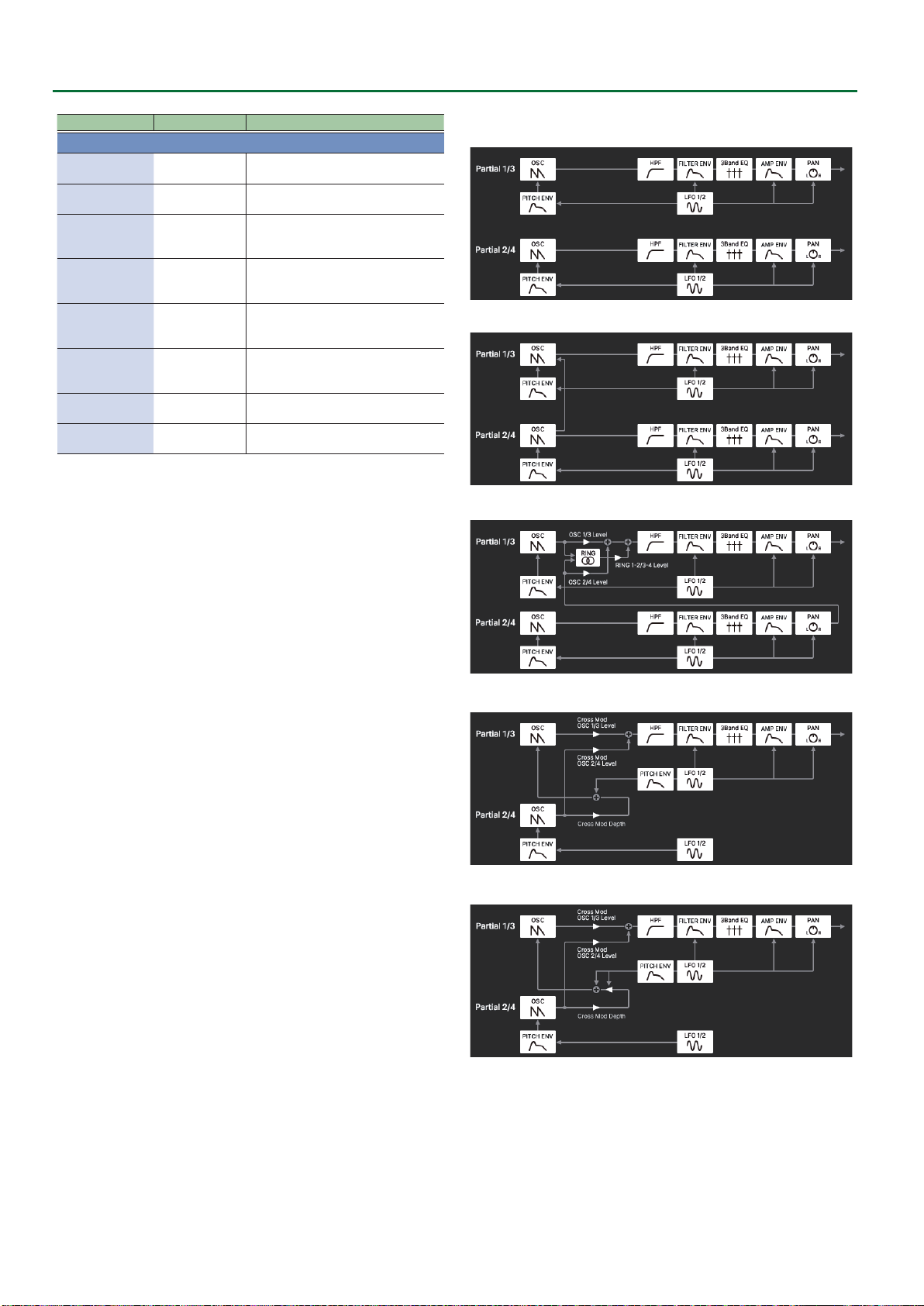
Tone Parameters
Parameter Value Explanation
CROSS MOD
1-2 Depth 0–10800 (cent)
3-4 Depth 0–10800 (cent)
OSC1 Level 0–127
OSC2 Level 0–127
OSC3 Level 0–127
OSC4 Level 0–127
XM2 1-2 Depth 0–127
XM2 3-4 Depth 0–127
Cross Modulation Depth when
Structure1-2 is “XMOD.”
Cross Modulation Depth when
Structure3-4 is “XMOD.”
Sets the partial 1 OSC level.
* This is valid when the Structure1-2 is
“XMOD” or “XMOD2.”
Sets the partial 2 OSC level.
* This is valid when the Structure1-2 is
“XMOD” or “XMOD2.”
Sets the partial 3 OSC level.
* This is valid when the Structure3-4 is
“XMOD” or “XMOD2.”
Sets the partial 4 OSC level.
* This is valid when the Structure3-4 is
“XMOD” or “XMOD2.”
Cross Modulation Depth when
Structure1-2 is “XMOD2.”
Cross Modulation Depth when
Structure3-4 is “XMOD2.”
OFF
SYNC
RING
XMOD
XMOD2
38
TONE/MFX
Tone Parameters
Parameter Value Explanation
MFX Switch OFF, ON Switches the MFX on/o.
MFX Type
MFX parameters
See “MFX/IFX
Parameters”
(p. 51)
Selects the MFX type.
Edit the parameters for the selected MFX.
The available parameters dier
depending on the type of the eects you
selected in MFX Type.
SEND
Chorus Send Level 0–127
Reverb Send Level 0–127
Adjusts the amount of chorus.
If you don’t want to add the chorus eect,
set it to “0.”
Adjusts the amount of reverb.
If you don’t want to add the reverb eect,
set it to “0.”
CONTROL
Species the MIDI message that will control the corresponding
MFX CONTROL parameter.
OFF MFX CONTROL will not be used.
Control Source
1–4
Control
Destination 1–4
Control Sens 1–4
CC01–31 Controller number 1–31
CC33–95 Controller number 33–95
BEND Pitch bend
AFTER TOUCH Aftertouch
SYS-CTRL1–4
Species the multi-eect parameters that are controlled by
MFX CONTROL.
The multi-eects parameters available for control will depend
on the multi-eects type.
-63–+63
Use the controller that is assigned by the
System Control Source 1–4.
Species the depth of MFX CONTROL.
Specify a positive (+) value if you want
to change the value of the assigned
destination in a positive direction (larger,
toward the right, faster, etc.), or specify a
negative (-) value if you want to change
the value in a negative direction (smaller,
toward the left, slower, etc.).
Larger values will allow a greater amount
of control.
Controlling a MFX via MIDI (MFX CONTROL)
You can use MIDI messages such as control change messages to
control the principal MFX parameters.
This capability is called “MFX CONTROL (multi-eects control).”
The editable parameters are pre-determined according to the MFX
type. You can specify up to four parameters for multi-eect control.
To use MFX CONTROL, you’ll need to specify which MIDI message
(Source) will aect which parameter (Destination), and how greatly
(Sens).
39
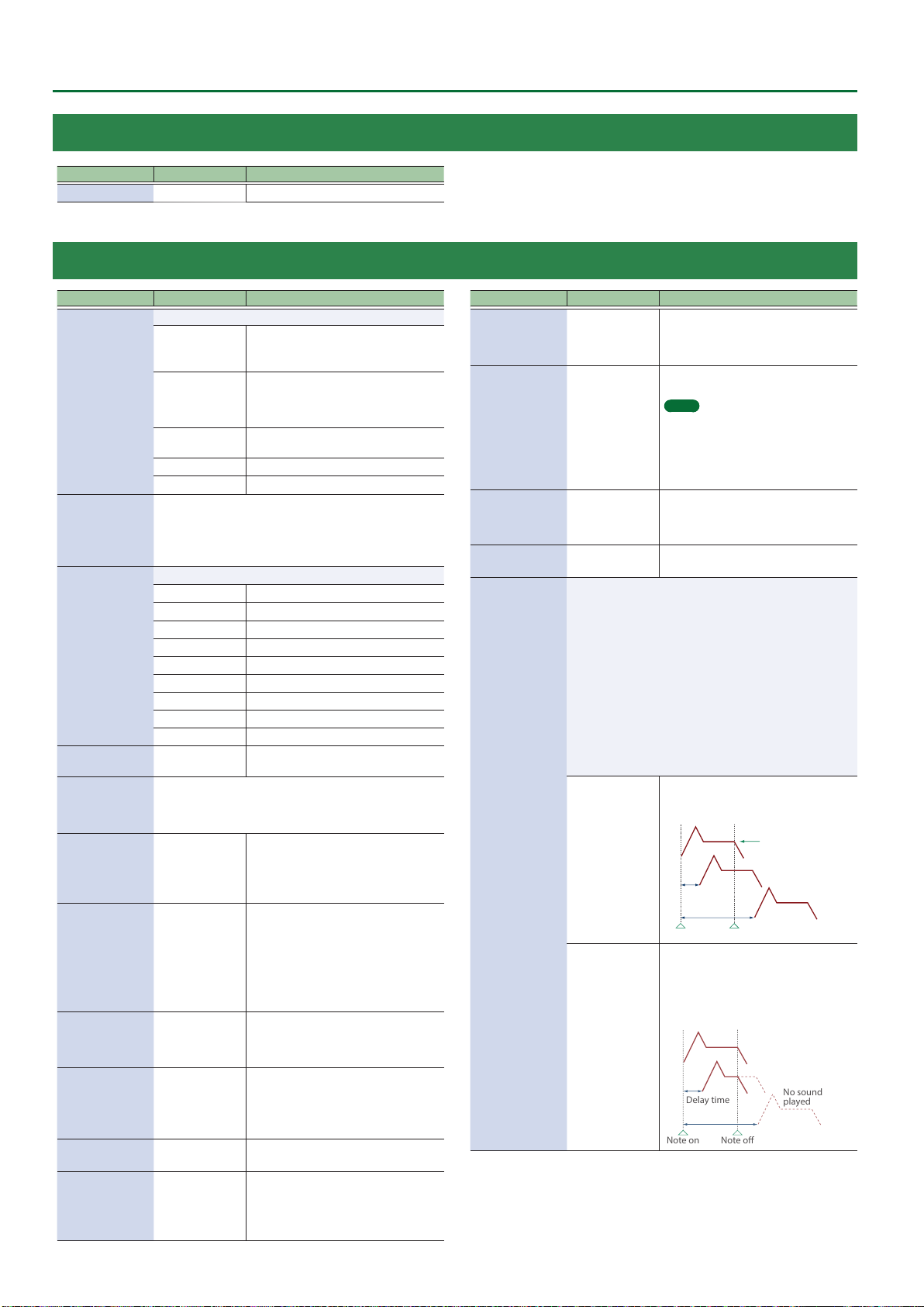
Tone Parameters
Note o
Note on
Note o
Delay time
Note on
No sound
played
TONE/PARTIAL
Parameter Value Explanation
Partial SW OFF, ON Turns each partial on/o.
TONE/PARTIAL/OSC
Parameter Value Explanation
Species the oscillator type.
PCM (INT A–D)
OSC Type
Wave LEFT/RIGHT
Waveform
VA Waveform
Invert Switch
PCM-Sync Wave
Gain -18–+12 [dB]
Pulse Width 0–127
PWM Depth -63–+63
Click Type
Fat 0–127
SuperSAW Detune 0–127
40
VA
PCM-Sync
SuperSAW SuperSAW is used.
Noise White noise is used.
Species the wave that is used when OSC Type is “PCM.”
Species the wave within the group specied by Wave Group.
If using mono, specify only the LEFT and leave RIGHT at “0: OFF.”
If using stereo, specify the RIGHT as well.
If you specify only RIGHT, no sound is heard.
Species the wave that is used when OSC Type is “VA.”
SAW Sawtooth wave
SQR Square wave
TRI Triangle wave
SIN sine wave
RAMP Ramp wave
JUNO Modulated sawtooth wave
TRI2 Triangle wave variation
TRI3 Triangle wave variation
SIN2 Sine wave variation
OFF, ON
Species the wave that is used when OSC Type is “PCM-Sync.”
The PCM-Sync oscillator is eective when specied as the
Slave (the sync-modulated partial 1 or 3) when Structure is set
to “SYNC.”
SOFT, HARD,
NATURAL, OFF
The wave of the number specied by the
Wave Group (INT A–D) and Wave LEFT/
RIGHT is used.
A numerically calculated analog-modeled
wave is generated.
The wave of the number specied by
Wave is used.
The wave of the number specied by
PCM-Sync Wave Number is used.
If this is “ON,” the phase of the VA
waveform is inverted.
Species the gain (amplitude) of the
waveform.
The value will change in 6 dB (decibel)
steps.
Each 6 dB increase doubles the gain.
This eect is produced when the
waveform is deformed by varying the
duty cycle of the pulse width.
It is eective when OSC Type is “VA,” and is
also eective with waveforms other than
SQR (square wave).
* If the value is 64, the pulse width has a
50%: 50% duty cycle.
Species the amount (depth) of LFO
applied to PW (Pulse Width).
PW is modulated according to the LFO2
setting.
Changes the sense of attack by varying
the position at which the sound starts.
This is available if OSC Type is “VA.”
However, HARD is eective only when
Waveform is “TRI,” “ TRI2,” “SIN,” or “SIN2.”
Boosts the low-frequency region.
* This is valid when the OSC Type is “VA.”
Adjusts the Detune depth for SuperSAW.
Higher values produce a deeper Detune
eect.
* This is valid when the OSC Type is
“SuperSAW.”
Parameter Value Explanation
Species the OSC level.
OSC Attenuator 0–255
FXM Switch OFF, ON
FXM Color 1–4
FXM Depth 0–16
Partial Delay
This produces a time delay between the moment a key is
pressed (or released), and the moment the partial actually
begins to sound. You can also make settings that shift the
timing at which each partial is sounded.
This diers from the Delay in the internal eects, in that by
changing the sound qualities of the delayed partials and
changing the pitch for each partial, you can also perform
arpeggio-like passages just by pressing one key.
You can also synchronize the partial delay time to the tempo
of the external MIDI sequencer.
If Legato Retrigger Interval is other than OFF, legato operation
occurs only when Delay Mode is NORMAL.
Also in this case, Legato Retrigger Interval operates as 0
(retriggers at each Delay Time).
Delay Mode
NORMAL
HOLD
255 is the reference value. If you want
only the self-oscillation of the lter to be
heard, set this to 0.
This sets whether FXM will be used (ON)
or not (OFF).
MEMO
FXM (Frequency Cross Modulation) uses
a specied waveform to apply frequency
modulation to the currently selected
waveform, creating complex overtones.
This is useful for creating dramatic sounds
or sound eects.
Species how FXM will perform
frequency modulation. Higher settings
result in a grainier sound, while lower
settings result in a more metallic sound.
Species the depth of the modulation
produced by FXM.
The partial begins to play after the
time specied in the Partial Delay Time
parameter has elapsed.
Delay time
Although the partial begins to play after
the time specied in the Partial Delay
Time parameter has elapsed, if the key is
released before the time specied in the
Partial Delay Time parameter has elapsed,
the partial is not played.
No Partial Delay

Tone Parameters
Note o
Delay time
Note on
Note o
Delay time
Note on
Range Lower
Range Upper
Fade Lower
Fade Upper
Level
Pitch
Range Lower
Range Upper
Fade Low
Fade Up
Level
Velocity
Parameter Value Explanation
Rather than being played while the key is
pressed, the partial begins to play once
the period of time specied in the Partial
Delay Time parameter has elapsed after
release of the key.
This is eective in situations such as when
simulating noises from guitars and other
KEY-OFF-NORMAL
instruments.
Delay Mode
Rather than being played while the key
is pressed, the partial begins to play
once the period of time specied in the
Partial Delay Time parameter has elapsed
after release of the key. Here, however,
changes in the TVA Envelope begin while
KEY-OFF-DECAY
the key is pressed, which in many cases
means that only the sound from the
release portion of the envelope is heard.
Delay Time Sync OFF, ON
Set this “ON” if you want the partial delay
time to synchronize with the tempo.
It species the delay time in terms of a
Delay Time (note) 1/64T–2
note value.
* This is available when Delay Time Sync
is “ON.”
It species the delay time without regard
Delay Time
0–1023
to the tempo.
* This is available when Delay Time Sync
is OFF.
TONE/PARTIAL/RANGE
Parameter Value Explanation
Key Range Lower C-1–G9
Key Range Upper C-1–G9
Key Fade Lower 0–127
Key Fade Upper 0–127
Velocity Range
Lower
Velocity Range
Upper
1–127
1–127
Velocity Fade Low 0–127
Velocity Fade Up 0–127
Specify the key range for each partial.
Make these settings when you want
dierent key ranges to play dierent
tones.
Specify the lower limit (Lower) and upper
limit (Upper) of the key range.
Species the degree to which the partial
is sounded by notes played below the
Keyboard Range Low.
If you don’t want the tone to sound at all,
set this parameter to “0.”
Species the degree to which the partial
is sounded by notes played above the
Keyboard Range Up.
If you don’t want the tone to sound at all,
set this parameter to “0.”
Specify the lower limit (Lower) and upper
limit (Upper) of the velocities that will
sound the partial.
Make these settings when you want
dierent partials to sound depending on
keyboard playing dynamics.
Species the degree to which the partial
is sounded by notes played more softly
than Velocity Range Low. If you don’t
want the tone to sound at all, set this
parameter to “0.”
Species the degree to which the partial
is sounded by notes played more strongly
than Velocity Range Up. If you don’t
want the tone to sound at all, set this
parameter to “0.”
41

Tone Parameters
C4C3C2C1 C5 C6 C7
0
+50
+100
+200
-50
-100-200
Key
Pitch
1 2 3 4 5 6 7
0
C4C3C2C1 C5 C6 C7
-50
-100
+50
+100
Key
Time
T1 T2 T3 T4
L1
L0
Pitch
Note on
T
:
Time L:Level
L3
L2
Note o
Time
L4
TONE/PARTIAL/PITCH
Parameter Value Explanation
Coarse Tune
Fine Tune
-48–+48
(semitone)
-50–+50 (cent)
Adjusts the pitch of the sound up or
down in semitone steps (+/-4 octaves).
Adjusts the pitch of the sound up or
down in 1-cent steps (+/-50 cents).
This species the width of random pitch
deviation that will occur each time a key
is pressed.
Random Depth 0–1200 [cent]
If you do not want the pitch to change
randomly, set this to “0.”
* These values are in units of cents
(1/100th of a semitone).
This species the amount of pitch change
that will occur when you play a key one
octave higher (i.e., 12 keys upward on the
keyboard).
If you want the pitch to rise one octave
as on a conventional keyboard, set this to
“+100.” If you want the pitch to rise two
octaves, set this to “+200.” Conversely, set
this to a negative (-) value if you want the
pitch to fall.
Pitch Keyfollow -200–+200
With a setting of “0,” all keys will produce
the same pitch.
Species the amount by which the
Vibrato Pitch Sens -100–+100
Pitch Depth of LFO1 is changed by the
program’s Modify Vib Depth.
Stereo Detune -50–+ 50 (cent)
Species the detune between LÕR when
outputting in stereo.
PITCH ENVELOPE
Adjusts the eect of the Pitch Envelope.
Higher settings will cause the pitch
envelope to produce greater change.
Depth -100–+100
Velocity Curve FIXED, 1–7
Negative (-) value will invert the shape of
the envelope.
If OSC Type () is other than VA, this is
limited to ±63.
Selects one of the following 7 curves that
will determine how keyboard playing
dynamics will aect the pitch envelope.
Set this to “FIXED” if you don’t want
the pitch envelope be aected by the
keyboard velocity.
Parameter Value Explanation
Use this setting if you want the pitch
envelope times (Time 2–Time 4) to be
aected by the keyboard location.
Based on the pitch envelope times for
the C4 key, positive (+) value will cause
notes higher than C4 to have increasingly
shorter times, and negative (-) value will
cause them to have increasingly longer
times.
Time Keyfollow -100–+100
Higher values will produce greater
change.
If this is ON, the pitch envelope is
LFO Trigger Switch OFF, ON
cyclically retriggered by LFO1.
* This is valid when the Envelope Mode
(p. 48) is “SUSTAIN.”
Specify the pitch envelope times
(Time 1–Time 4).
Higher settings will result in a longer
time until the next pitch is reached. (For
example, Time 2 is the time over which
the pitch changes from Level 1 to Level 2.)
Time1 (Attack)
Time2
Time3 (Decay)
0–1023
* If ADSR Envelope Switch is “ON,” the
Time 2 has no eect.
Time4 (Release)
Specify the pitch envelope levels
(Level 0–Level 4).
It determines how much the pitch
Level0
Level1
Level2
Level3 (Sustain)
Level4
-511–+511
changes from the reference pitch (the
value set with Coarse Tune or Fine Tune
on the Pitch screen) at each point.
Positive (+) value will cause the pitch to
be higher than the standard pitch, and
negative (-) value will cause it to be lower.
* If ADSR Envelope Switch (p. 48) is
“ON,” only Level 3 (Sustain) has an
eect. Also in this case, settings with a
negative value are ignored.
Velocity Sens -100–+100
T1 Velocity Sens -100–+100
T4 Velocity Sens -100–+100
42
Keyboard playing dynamics can be
used to control the depth of the pitch
envelope.
If you want the pitch envelope to have
more eect for strongly played notes, set
this parameter to a positive (+) value.
If you want the pitch envelope to have
less eect for strongly played notes, set
this to a negative (-) value.
This allows keyboard dynamics to aect
the Time 1 of the Pitch envelope.
If you want Time 1 to be speeded up for
strongly played notes, set this parameter
to a positive “+” value.
If you want it to be slowed down, set this
to a negative “-” value.
Use this parameter when you want key
release speed to aect the Time 4 value of
the pitch envelope.
If you want Time 4 to be speeded up for
quickly released notes, set this parameter
to a positive (+) value.
If you want it to be slowed down, set this
to a negative (-) value.

LPF BPF HPF PKG
Level
Frequency
Cuto Frequency
High
Low
parameter value
TONE/PARTIAL/FILTER
Tone Parameters
Parameter Value Explanation
FILTER
Selects the type of lter.
MEMO
TVF stands for Time Variant Filter, a lter
Filter Type
TVF Type
VCF Type
TVF, VCF
Selects the type of TVF lter.
* If Filter Type is set to VCF, this will be LPF.
OFF No lter is used.
LPF
BPF
HPF
PKG
LPF2
LPF3
VCF1,
J P,
MG,
P5
that lets you specify in detail how the
frequency components of the sound
change over time.
If you select VCF, the polyphony will be
lower than if you select TVF.
Low Pass Filter.
This cuts the frequencies in the region
above the cuto frequency (Cuto
Frequency).
Since this cuts the high-frequency
region, the sound becomes more mellow.
This is the most common lter used in
synthesizers.
Band Pass Filter. This leaves only the
frequencies in the region of the cuto
frequency (Cuto Frequency), and cuts
the rest. This can be useful when creating
distinctive sounds.
High Pass Filter.
This cuts the frequencies in the region
below the cuto frequency (Cuto
Frequency).
This is suitable for creating percussive
sounds emphasizing their higher tones.
Peaking Filter.
This emphasizes the frequencies in the
region of the cuto frequency (Cuto
Frequency).
You can use this to create wah-wah
eects by employing an LFO to change
the cuto frequency cyclically.
Low Pass Filter 2.
Although frequency components above
the Cuto frequency (Cuto Frequency)
are cut, the sensitivity of this lter is half
that of the LPF.
This makes it a comparatively warmer low
pass lter. This lter is good for use with
simulated instrument sounds such as the
acoustic piano.
* If you set “LPF2,” the setting for the
Resonance parameter (p. 43) will be
ignored.
Low Pass Filter 3.
Although frequency components
above the Cuto frequency (Cuto
Frequency) are cut, the sensitivity of this
lter changes according to the Cuto
frequency.
While this lter is also good for use with
simulated acoustic instrument sounds,
the nuance it exhibits diers from that
of the LPF2, even with the same TVF
Envelope settings.
* If you set “LPF3,” the setting for the
Resonance parameter (p. 43) will be
ignored.
Each setting simulates the operation of
an analog synthesizer’s LPF. In particular,
MG, JP, and P5 are types that are suitable
for reproducing synthesizer sounds of
the past.
* This is valid when the Filter Type is “VCF.”
Parameter Value Explanation
Selects the slope (steepness) of the lter.
For VCF, you can choose -12, -18, or -24.
For TVF, only -12 or -24 can be selected.
If Filter Type is TVF, the following
Filter Slope
-12, -18, -24
(dB/Oct)
limitations apply.
¹ You can specify only -12 dB or -24 dB. If
you specify -18 dB, the sound generator
operates internally with the -12 dB
setting.
¹ If you specify -24 dB, the polyphony will
be lower than if you specify -12 dB.
Emphasizes the portion of the sound in
the region of the cuto frequency, adding
character to the sound. Excessively high
settings can produce oscillation, causing
the sound to distort.
Resonance 0–1023
Use this parameter when changing the
resonance to be applied as a result of
changes in playing velocity.
Reso Velo Sens -100–+100
Specify a positive “+” value if you want
resonance to increase when you play
strongly, or a negative “-” value if you
want it to decrease.
Species how the TVF Depth of LFO1
Vib Cuto Sens -100–+100
is aected by the program’s Modify Vib
Depth.
Species the cuto frequency of the -6 dB
HPF Cuto 0–1023
high-pass lter.
* This is valid when the Filter Type is “VCF.”
Selects the frequency at which the
lter begins to have an eect on the
waveform’s frequency components.
With “LPF/LPF2/LPF3” selected for the
TVF Filter Type parameter, lower cuto
frequency settings reduce a tone’s upper
harmonics for a more rounded, warmer
sound. Higher settings make it sound
brighter.
If “BPF” is selected for the Filter Type,
Cuto Freq 0–1023
harmonic components will change
depending on the TVF Cuto Frequency
setting. This can be useful when creating
distinctive sounds.
With “HPF” selected, higher Cuto
Frequency settings will reduce lower
harmonics to emphasize just the brighter
components of the sound.
With “PKG” selected, the harmonics to
be emphasized will vary depending on
Cuto Frequency setting.
43
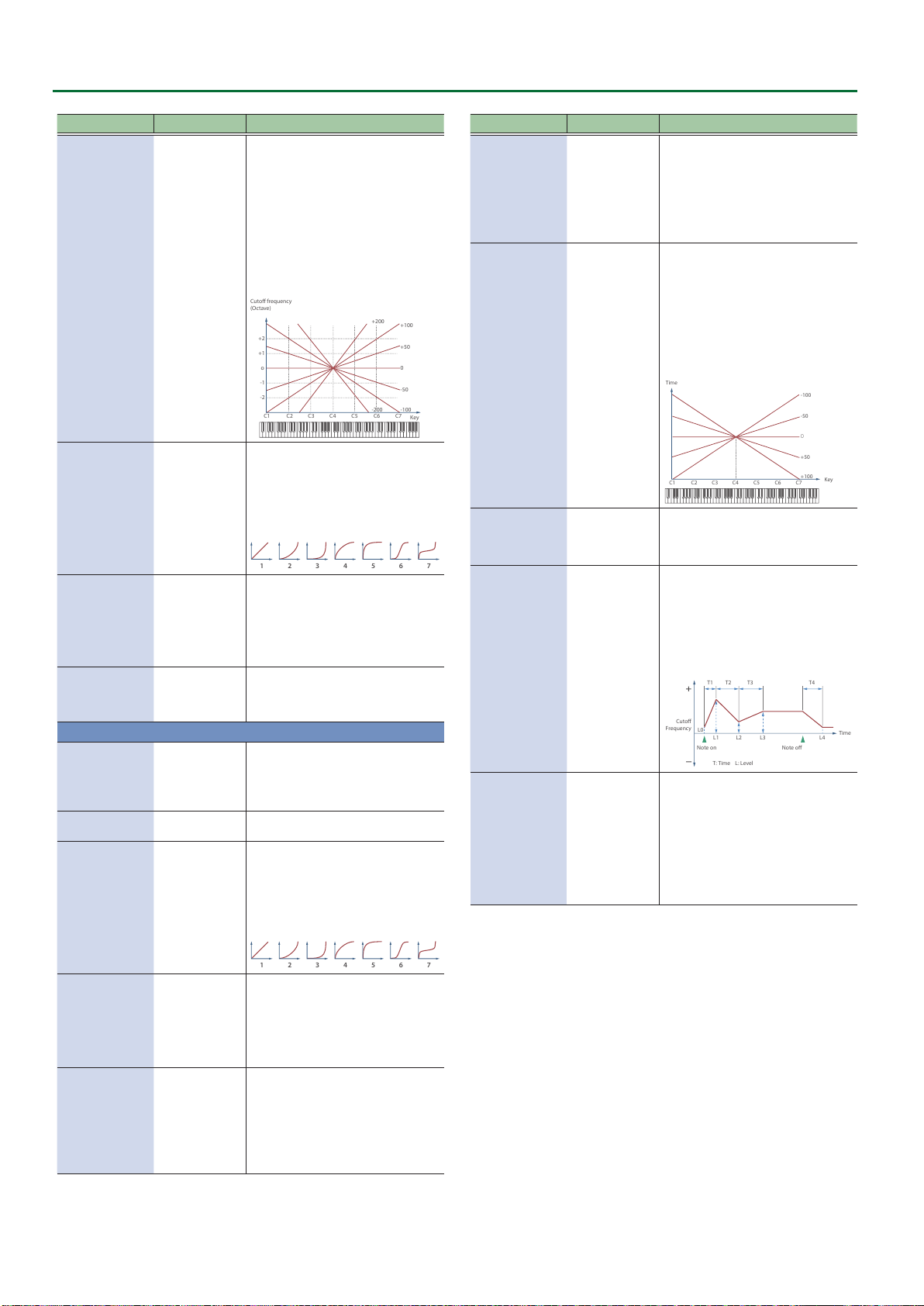
Tone Parameters
-200
C4C3C2C1 C5 C6 C7
+50
+100
-100
o
-1
-2
+1
+2
Cuto frequency
(Octave)
Key
0
+200
-50
-200
1 2 3 4 5 6 7
1 2 3 4 5 6 7
0
C4C3C2C1 C5 C6 C7
-50
-100
+50
+100
Key
Time
T1 T2 T3 T4
Note o
Cuto
Frequency
Time
Note on
T: Time L: Level
L3L0L2L1 L4
Parameter Value Explanation
Use this parameter if you want the cuto
frequency to change according to the key
that is pressed.
Relative to the cuto frequency at the
key specied by Cuto Keyfollow Base
Point, positive “+” values cause the cuto
frequency to become higher as you play
above the reference key, and negative
“-” values cause the cuto frequency to
become lower.
Higher values will produce greater
Cuto Keyfollow -200–+200
change.
Selects one of the following seven curves
that determine how keyboard playing
dynamics (velocity) inuence the cuto
frequency.
Cuto Velo Curve FIXED, 1–7
Set this to “FIXED” if you don’t want the
Cuto frequency to be aected by the
keyboard velocity.
Use this parameter when changing
the cuto frequency to be applied as
a result of changes in playing velocity.
Cuto Velo Sens -100–+100
Specify a positive “+” value if you want
the cuto frequency to raise when you
play strongly, or a negative “-” value if you
want it to lower.
Species the reference key when using
Cut KF Base Point 0–127
Keyfollow to modify the cuto frequency.
If this is 60, the C4 key (middle C) is the
reference key.
FILTER ENVELOPE
Species the depth of the Filter envelope.
Higher settings increase the change
Depth -63–+63
Fine Depth -63–+63
Velocity Curve FIXED, 1–7
produced by the Filter envelope.
Negative (-) value will invert the shape of
the envelope.
Finely adjusts the depth of the lter
envelope.
Selects one of the following seven types
of curve by which keyboard playing
dynamics aect the depth of the lter
envelope.
If you don’t want keyboard playing
dynamics to aect the lter envelope
depth, specify “FIXED.”
Parameter Value Explanation
Specify this if you want key release
velocity to aect Time 4 of the lter
envelope.
T4 Velocity Sens -100–+100
If you want Time 4 to be speeded up for
quickly released notes, set this parameter
to a positive (+) value.
If you want it to be slowed down, set this
to a negative (-) value.
Specify this if you want the lter envelope
times (Time 2–Time 4) to vary depending
on the keyboard position you play.
Relative to the lter envelope times at
the C4 key (middle C), positive “+” values
shorten the times for notes played in the
region above C4, and negative “-” values
lengthen the times.
Higher values will produce greater
Time Keyfollow -100–+100
change.
If this is “ON,” the lter envelope is
LFO Trigger Switch OFF, ON
cyclically retriggered by LFO1.
* This is valid when the Envelope Mode
(p. 48) is “SUSTAIN.”
Specify the lter envelope times
(Time 1–Time 4).
Higher settings will lengthen the time
until the next cuto frequency level is
reached. (For example, Time 2 is the time
Time1 (Attack)
Time2
Time3 (Decay)
0–1023
over which Level 1 will change to Level 2.)
* If ADSR Envelope Switch (p. 48) is
“ON,” the Time 2 has no eect.
Time4 (Release)
Specify the lter envelope levels
(Level 0–Level 4).
Level0
Level1
Level2
Level3 (Sustain)
Level4
0–1023
Specify the amount of cuto frequency
change at each point relative to the
reference cuto frequency (the cuto
frequency value specied in the Filter
screen).
* If ADSR Envelope Switch (p. 48) is
“ON,” only Level 3 (Sustain) has an
eect.
Velocity Sens -100–+100
T1 Velocity Sens -100–+100
44
Specify this if you want keyboard playing
dynamics to aect the lter envelope
depth.
Specify a positive “+” value if you want the
lter envelope to apply more deeply as
you play more strongly, or a negative “-”
value if you want it to apply less deeply.
Specify this if you want keyboard playing
dynamics to aect Time 1 of the lter
envelope.
If you want Time 1 to be speeded up for
strongly played notes, set this parameter
to a positive “+” value. If you want it to
be slowed down, set this to a negative
“-” value.
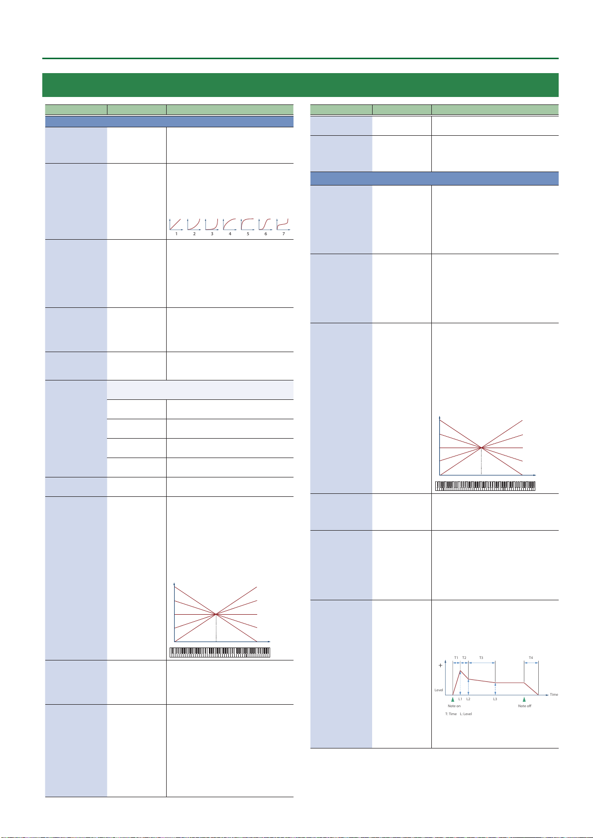
1 2 3 4 5 6 7
o
R
Pan
Time
T1 T2 T3 T4
L3
L1
L2
Note o
Level
Time
Note on
T: Time L: Level
TONE/PARTIAL/AMP
Tone Parameters
Parameter Value Explanation
AMP
Sets the volume of the partial.
Level
0–127
Velocity Curve FIXED, 1–7
Velocity Sens -100–+100
Bias Level -100–+100
Bias Position 0–127
Selects the direction in which change will occur starting from
the Bias Position.
LOWER
Bias Direction
UPPER
LOWER&UPPER
ALL
Pan L64–63R
Pan Keyfollow -100–+100
This setting is useful primarily for
adjusting the volume balance between
partials.
Selects one of the following seven curves
that determine how keyboard dynamics
will aect the volume. Set this to “FIXED”
if you don’t want the volume of the
partial to be aected by the keyboard
velocity.
Set this when you want the volume of the
partial to change depending on the force
with which you press the keys.
Set this to a positive (+) value to have the
changes in partial volume increase the
more forcefully the keys are played; to
make the partial play more softly as you
play harder, set this to a negative (-) value.
Adjusts the angle of the volume change
that will occur in the selected Bias Direction.
Higher values will produce greater
change. Negative (-) values will invert the
change direction.
Species the key relative to which the
volume will be modied.
A setting of 64 is the C4 key (middle C).
The volume will be modied for the
keyboard area below the Bias Point.
The volume will be modied for the
keyboard area above the Bias Point.
The volume will be modied symmetrically
toward the left and right of the Bias Point.
The volume changes linearly with the bias
point at the center.
Sets the pan of the partial. “L64” is far left,
“0” is center, and “63R” is far right.
Use this parameter if you want key
position to aect panning.
Positive (+) value will cause notes higher
than C4 key (center C) to be panned
increasingly further toward the right,
and negative (-) value will cause notes
higher than C4 key (center C) to be
panned toward the left. Higher values will
produce greater change.
L
C4C3C2C1 C5 C6 C7
Parameter Value Explanation
Vibrato Level Sens -100–+100
Species how the program’s Modify Vib
Depth aects the Amp Depth of LFO1.
Adjusts the amount of width when
Stereo Width 0–100
outputting in stereo.
This has no eect when outputting in
mono.
AMP ENVELOPE
Specify this if you want keyboard
dynamics to aect the AMP envelope’s
Time 1.
T1 Velocity Sens -100–+100
T4 Velocity Sens -100–+100
Time Keyfollow -100–+100
LFO Trigger Switch OFF, ON
Time1 (Attack)
Time2
Time3 (Decay)
+100
+50
0
-50
-100
Key
Time4 (Release)
0–1023
If you want Time 1 to be speeded up for
strongly played notes, set this parameter
to a positive (+) value.
If you want it to be slowed down, set this
to a negative (-) value.
Specify this if you want key release
velocity to aect the AMP envelope’s
Time 4.
If you want Time 4 to be speeded up for
quickly released notes, set this parameter
to a positive (+) value.
If you want it to be slowed down, set this
to a negative (-) value.
Specify this if you want keyboard position
to aect the AMP envelope’s times
(Time 2–Time 4).
Relative to the AMP envelope times at
the C4 key (middle C), positive (+) values
cause the times to shorten as you play
higher on the keyboard, and negative
(-) values cause the times to lengthen.
Higher values will produce greater
change.
-100
-50
0
+50
+100
C4C3C2C1 C5 C6 C7
Key
If this is ON, the amp envelope is cyclically
retriggered by LFO1.
* This is valid when the Envelope Mode
(p. 48) is “SUSTAIN.”
Specify the AMP envelope times
(Time 1–Time 4).
Higher settings lengthen the time until
the next volume level is reached. (For
example, Time 2 is the time over which
Level 1 will change to Level 2.)
* If ADSR Envelope Switch (p. 48) is
“ON,” the Time 2 has no eect.
Specify the AMP envelope levels
(Level 1–Level 3).
These specify the amount of change
at each point relative to the reference
volume (the partial level value specied
in the Amp screen).
Rand Pan Depth 0–63
Alt Pan Depth L64–63R
Use this parameter when you want the
stereo location to change randomly each
time you press a key.
Level1
Level2
Level3 (Sustain)
0–1023
Higher values will produce a greater
amount of change.
This setting causes panning to be
alternated between left and right each
time a key is pressed.
Higher values will produce a greater
amount of change. “L” or “R” settings will
* If ADSR Envelope Switch (p. 48) is
“ON,” only Level 3 (Sustain) has an
eect.
reverse the order in which the pan will
alternate between left and right.
For example if two partials are set to “L”
and “R” respectively, the panning of the
two tones will alternate each time they
are played.
45

Tone Parameters
C4C3C2C1 C5 C6 C7
Key
Time
0
-50
-100
+50
+100
TONE/PARTIAL/LFO1, LFO2
Parameter Value Explanation
Selects the waveform of the LFO.
SIN Sine wave
TRI Triangle wave
SAW-UP Sawtooth wave
SAW-DW Sawtooth wave (negative polarity)
SQR Square wave
RND Random wave
TRP Trapezoidal wave
Waveform
S&H
Sample & Hold wave (one time per cycle,
LFO value is changed)
CHS Chaos wave
Modied sine wave. The amplitude of a
VSIN
sine wave is randomly varied once each
cycle.
A waveform generated by the data
STEP
specied by LFO Step 1–16.
This produces stepped change with a
xed pattern similar to a step modulator.
Rate Sync
OFF, ON
Set this “ON” if you want the LFO rate to
synchronize with the tempo.
Species the LFO rate in terms of a note
Rate (note)
1/64T–4
value.
* This is valid when the Rate Sync is “ON.”
Species the LFO rate without regard to
the tempo.
Rate
0–1023
Higher values produce a faster LFO rate
(a shorter cycle).
* This is valid when the Rate Sync is “OFF.”
Raises or lowers the LFO waveform
relative to the central value (pitch or
cuto frequency).
Oset
-100–100
Positive (+) value will move the waveform
so that modulation will occur from
the central value upward. Negative (-)
value will move the waveform so that
modulation will occur from the central
value downward.
Subtly changes the LFO cycle speed
(Rate parameter) each time you press
Rate Detune
0–127
a key.
Higher values produce greater change.
* This is invalid when Rate is set to “note.”
Species the time elapsed before the LFO
eect is applied (the eect continues)
Delay Time
0–1023
after the key is pressed (or released).
* After referring to “How to Apply the
LFO,” change the setting until the
desired eect is achieved.
Adjusts the value for the Delay Time
parameter depending on the key
position, relative to the C4 key (center C).
To decrease the time that elapses before
the LFO eect is applied (the eect is
continuous) with each higher key that is
pressed in the upper registers, select a
positive (+) value; to increase the elapsed
time, select a negative (-) value. Higher
values will produce greater change. If
you do not want the elapsed time before
Delay Time KF
-100–+100
the LFO eect is applied (the eect is
continuous) to change according to the
key pressed, set this to “0.”
Parameter Value Explanation
Species the time over which the LFO
amplitude will reach the maximum
Fade Time
0–1023
(minimum).
* After referring to “How to Apply the
LFO” (p. 47), change the setting until
the desired eect is achieved.
Species whether the LFO cycle will be
Key Trigger Switch
OFF, ON
synchronized to begin when the key is
pressed (ON) or not (OFF).
Species how deeply the LFO will aect
Pitch Depth
-100–100
pitch.
* If OSC Type (p. 40) is other than VA,
the range is limited to -63–+63.
Filter Depth
Amp Depth
-100–100
-100–100
Species how deeply the LFO will aect
the cuto frequency.
Species how deeply the LFO will aect
the volume.
Species how deeply the LFO will aect
the pan.
MEMO
Positive (+) and negative (-) value for the
Depth parameter result in diering kinds
of change in pitch and volume.
For example, if you set the Depth
Pan Depth
-63–+63
parameter to a positive (+) value for one
partial, and set another partial to the same
numerical value, but make it negative (-),
the modulation phase for the two partials
will be the reverse of each other.
This allows you to shift back and forth
between two dierent partials, or combine
it with the Pan setting to cyclically change
the location of the sound image.
Species the LFO’s starting phase value when Key Trigger is ON.
* This has no eect if Waveform is “RND,” “S&H,” or “CHS.”
Phase Position
0 1 cycle
1 1/4 cycle
2 1/2 cycle
3 3/4 cycle
Step Size 1–16
Species the length of the step change.
* This is eective if Waveform is “STEP.”
Specify the Depth value of each step.
If you want to specify this in pitch scale
degrees (100 cents), the settings are as
follows.
1 Pitch Depth: 51, Step: multiples of 6
up to one octave of change
Step1–16 -72–+72
2 Pitch Depth: 74, Step: multiples of 3
up to two octaves of change
3 Pitch Depth: 89, Step: multiples of 2
up to three octaves of change
* If OSC Type is not VA, the Pitch Depth
setting range is limited to -63–+63, so
only “1” above is possible.
Step Curve1–16 0–36
Species the type of curve at each step.
Ø “Step curve types”
Fade Mode
46
ON-OUT
OFF-IN
OFF-OUT
ON-IN
Species how the LFO will be applied.
* After referring to “How to Apply the
LFO,” change the setting until the
desired eect is achieved.

Tone Parameters
1 2
5 6
3 4
7 8 9 10
11
15
12 13 14
16 17 18 19
20 21 22 23
24 25 26 27
28 29 30 31
32 33 34 35
36
Note on
high (more)
low (less)
Pitch
Cuto Frequency
Level
Pan
Delay
Time
Fade Time
Depth
high (more)
low (less)
Pitch
Cuto Frequency
Level
Pan
Note on
Delay Time
Fade Time
Depth
high (more)
low (less)
Delay
Time
Fade Time
Depth
Note
o
Note
on
Pitch
Cuto Frequency
Level
Pan
Note on
high (more)
low (less)
Delay
Time
Fade Time
Depth
Note o
Pitch
Cuto Frequency
Level
Pan
Step curve types
Step Curve 0
Curve Type 1–6 (variations of square wave)
Curve Type 7–10 (variations of ascending saw)
Curve Type 32–36 (other variations)
How to Apply the LFO
Apply the LFO gradually after the key is pressed
Fade Mode: ON-IN
Curve Type 11–15 (variations of descending saw)
Curve Type 16–19 (variations of ascending exponential)
Curve Type 20–23 (variations of descending exponential)
Curve Type 24–27 (variations of ascending charging curve)
Apply the LFO immediately when the key is pressed, and then
gradually begin to decrease the eect
Fade Mode: ON-OUT
Apply the LFO gradually after the key is released
Fade Mode: OFF-IN
Apply the LFO from when the key is pressed until it is released, and
gradually begin to decrease the eect when the key is released
Fade Mode: OFF-OUT
Curve Type 28–31 (variations of descending charging curve)
47

Tone Parameters
TONE/PARTIAL/PARTIAL EQ
Parameter Value Explanation
Switch OFF, ON Turns the equalizer on/o for each partial.
Low Gain -24.0–+24.0 (dB) Gain of the low range.
Low Frequency 20–16000 (Hz) Frequency of the low range.
Mid Gain -24.0–+24.0 (dB) Gain of the middle range.
Mid Frequency 20–16000 (Hz) Frequency of the middle range.
Mid Q 0.5–16.0 (0.1step)
High Gain -24.0–+24.0 (dB) Gain of the high range
High Frequency 20–16000 (Hz) Frequency of the high range.
Width of the middle range.
Set a higher value to narrow the range to
be aected.
TONE/PARTIAL/OUTPUT
Parameter Value Explanation
Output Assign DRY, MFX
Chorus Send Level 0–127
Reverb Send Level 0–127
Species how the sound of each partial
will be output.
Species the level of the signal sent to the
chorus for each partial.
Species the level of the signal sent to the
reverb for each partial.
TONE/PARTIAL/CONTROL
Parameter Value Explanation
This imitates the operation of the ADSR
envelope that is provided on an analog
synthesizer.
ADSR Envelope
Switch
Envelope Mode
Damper Free Note OFF, 1–127
D.Free Decay
Oset
Receive Bender OFF, ON
Receive
Expression
Receive Hold-1 OFF, ON
Redamper Switch OFF, ON
Soft EQ Sens 0–100
Wave Tempo Sync
OFF, ON
Species the envelope mode.
NO-SUS
SUSTAIN
-100–+100
OFF, ON
OFF, ON
* If ADSR Envelope Switch is “ON,”
the “Time 2” parameters of Pitch/
Filter/Amp Env Time respectively
are ignored, and only the “Level 3”
parameters of Pitch/Filter/Amp Env
Level are valid.
The envelope transitions to the release
segment after passing Time 3 regardless
of the note-o timing, operating
according to the times specied by the
envelope.
The Envelope Level 3 is held from when
the envelope Time 3 has elapsed until
note-o.
When note-o occurs, the envelope
transitions from the current value to the
Time 4 segment (release segment).
For notes above the specied note
number, the Envelope Mode operates as
“NO-SUS.”
Use this to simulate the undamped
region of a piano sound.
Species a ne adjustment to the time
over which the sound decays when the
Damper Free Note eect is applied.
Species for each partial whether MIDI
pitch bend messages are received (ON)
or not received (OFF).
Species for each partial whether MIDI
expression messages are received (ON)
or not received (OFF).
Species for each partial whether MIDI
hold 1 messages are received (ON) or not
received (OFF).
If Redamper Switch is ON, you can
perform the Half Damper operations
used for piano sounds.
However, the following conditions
must be satised in order to use this
operation.
¹ Envelope Mode is NO-SUS
¹ Amp Envelope’s Level 1 and 2 are 1 or
greater
¹ Amp Envelope’s Times are Time 3 > Time4
Increases the proportion by which the
EQ’s HighGain is lowered by the amount
of pedal.
With a setting of “0,” this has no eect.
Turn this on to match the phrase loop
with the clock (tempo).
* This is enabled with when you select
a waveform for which a tempo (BPM)
is shown.
48
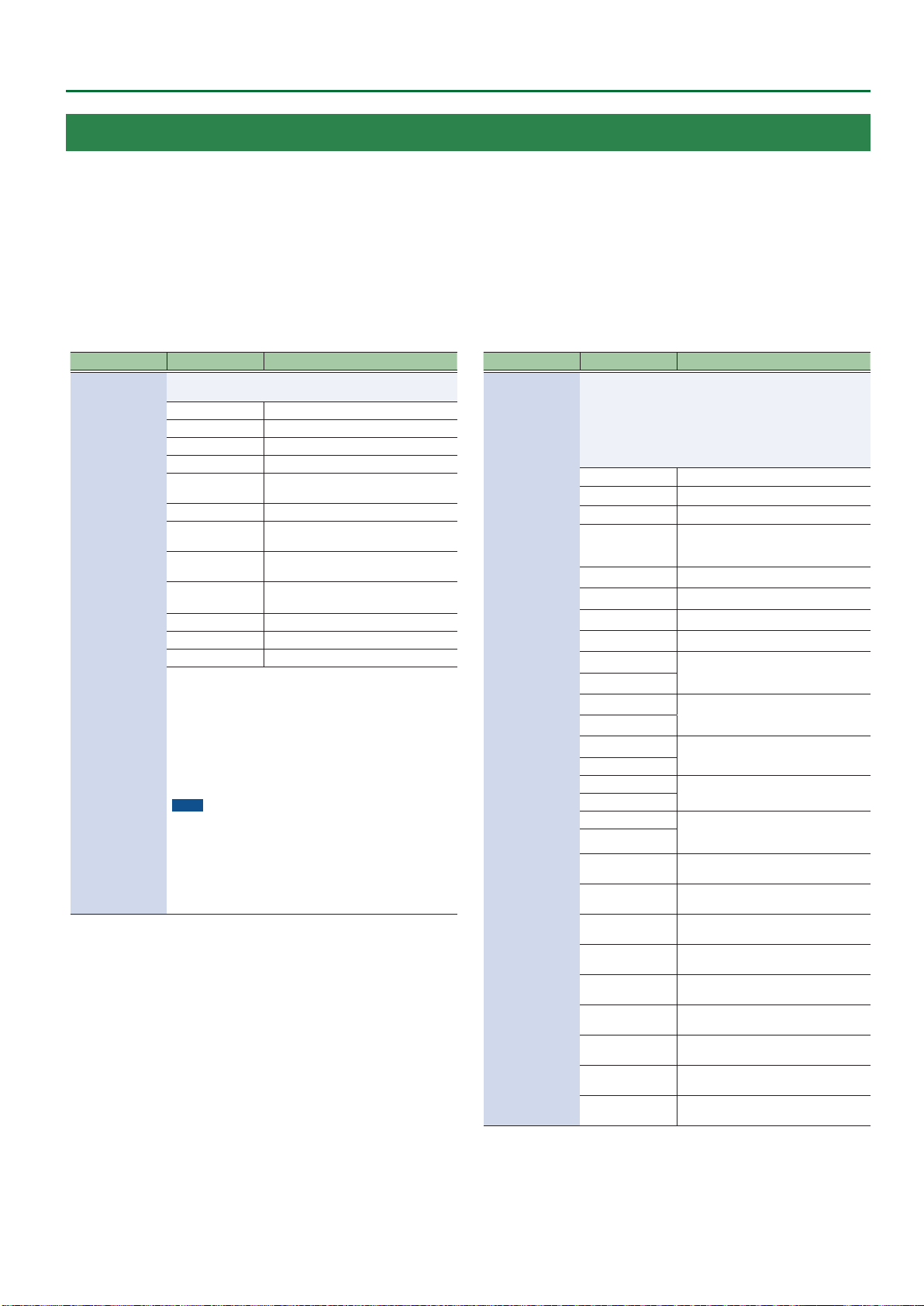
Tone Parameters
TONE/PARTIAL/MATRIX CONTROL
Ordinarily, if you wanted to change partial parameters using an external MIDI device, you would need to send System Exclusive messages-MIDI messages
designed exclusively for the Aerophone. However, System Exclusive messages tend to be complicated, and the amount of data that needs to be transmitted can
get quite large.
For that reason, a number of the more typical of the Aerophone’s partial parameters have been designed so they accept the use of Control Change (or other) MIDI
messages for the purpose of making changes in their values. This provides you with a variety of means of changing the way tones are played.
The function which allows you use MIDI messages to make these changes in realtime to the partial parameters is called the “Matrix Control.”
Up to four Matrix Controls can be used in a single tone.
To use Matrix Control, you specify which MIDI message (Source) controls which parameter (Destination) and how deeply (Sens: sensitivity).
Parameter Value Explanation
Sets the MIDI message used to change the partial parameter
with the Matrix Control.
OFF Matrix control will not be used.
CC01–31, CC33–95 Controller numbers 1–31, 33–95
BEND Pitch bend
AFTER TOUCH Aftertouch
MIDI messages assigned by the SYSTEM
parameters SYS-CTRL 1–4
Keyfollow (keyboard position with C4
as 0)
Tempo specied by the tempo assign
source
LFO 1
LFO 2
Source
SYS-CTRL1–4
VELOCITY Velocity (pressure you press a key with)
KEYFOLLOW
TEMPO
LFO1, LFO2
PIT-ENV Pitch envelope
FLT-ENV Filter envelope
AMP-ENV Amp envelope
* Velocity and Keyfollow correspond to Note messages.
* Although there are no MIDI messages for LFO 1 through
AMP Envelope, they can be used as Matrix Control. In this
case, you can change the partial settings in realtime by
playing tones.
* If you want to use common controllers for the entire
Aerophone, select “SYS-CTRL1”–”SYS-CTRL4.” MIDI messages
used as System Control 1–4 are set with the System Control
Source1–4.
NOTE
There are parameters that determine whether or not Pitch
Bend, Controller Number 11 (Expression) and Controller
Number 64 (Hold 1) are received (p. 48). When these
settings are “ON,” and the MIDI messages are received, then
when any change is made in the settings of the desired
parameter, the Pitch Bend, Expression, and Hold 1 settings
also change simultaneously. If you want to change the
targeted parameters only, then set these to “OFF.”
Parameter Value Explanation
Selects the partial parameter that is to be controlled when
using the Matrix Control. The following parameters can be
controlled.
When not controlling parameters with the Matrix Control, set
this to “OFF.”
Up to four parameters can be specied for each Matrix
Control, and controlled simultaneously.
OFF Matrix control will not be used.
PCH Changes the pitch.
CUT Changes the cuto frequency.
Emphasizes the overtones in the region
of the cuto frequency, adding character
to the sound.
Changes the vibrato depth.
Changes the wah depth.
Changes the tremolo depth.
Changes the eect that the LFO will
have on pan.
The speed will not change if LFO Rate is
set to “note.”
Changes the Time 1 of the PITCH
envelope.
Changes the Time 2 and Env Time 3 of
the PITCH envelope.
Changes the Time 4 of the PITCH
envelope.
Changes the Time 1 of the FILTER
envelope.
Changes the Time 2 and Env Time 3 of
the FILTER envelope.
Changes the Time 4 of the FILTER
envelope.
Changes the Time 1 of the AMP
envelope.
Changes the Time 2 and Env Time 3 of
the AMP envelope.
Changes the Time 4 of the AMP
envelope.
Destination 1–4
RES
LEV Changes the volume level.
PAN Changes the pan.
CHO Changes the amount of chorus.
REV Changes the amount of reverb.
PIT-LFO1
PIT-LFO2
FLT-LFO1
FLT-LFO2
AMP-LFO1
AMP-LFO2
PAN-LFO1
PAN-LFO2
LFO1-RATE Changes the speed of the LFO cycles.
LFO2-RATE
PIT-ATK
PIT-DCY
PIT-REL
FLT-ATK
FLT-DCY
FLT-REL
AMP-ATK
AMP-DCY
AMP-REL
49

Tone Parameters
Parameter Value Explanation
If the Matrix Control is used to split
partials, set the Velocity Control (p. 36)
to “OFF.”
¹ If the Matrix Control is used to split
partials, we recommend setting the
Sens to “+63.” Selecting a lower value
may prevent switching of the partials.
Furthermore, if you want to reverse the
eect, set the value to “-63.”
¹ If you want to use matrix control to
switch smoothly between partials, use
the Velocity Fade Low and Velocity
Fade Up (p. 41). The higher the
values set, the smoother the switch is
between the partials.
Changing the depth of frequency
modulation produced by FXM
Applies a change to MFX CONTROL 1–4
Source.
If this is specied for more than one
partial, the result will be the summed
values.
This setting is valid only for the carrier
partial (Partial 1 or 3), and applies
change to the CROSS MOD 1-2 Depth or
CROSS MOD 3-4 Depth.
Species the step position.
In this case, the Sens value is ignored.
* This is valid when the LFO1/LFO2
Waveform (p. 46) is “STEP.”
Applies change to Super-SAW Detune.
* This is valid when the OSC Type
(p. 40) is “SuperSAW.”
Changes the depth of the PITCH envelope.
Changes the depth of the FILTER envelope.
Applies change to XMOD2 1-2 (3-4)
Depth.
* This is valid when the Structure 1-2
(3-4) (p. 37) is “XMOD2.”
Applies change to RING OSC1 Level.
* This is valid when the Structure 1-2
(3-4) (p. 37) is “RING.”
Applies change to RING OSC2 Level.
* This is valid when the Structure 1-2
(3-4) (p. 37) is “RING.”
Applies change to CROSS MOD OSC1
Level.
* This is valid when the Structure 1-2
(3-4) (p. 37) is “XMOD” or “XMOD2.”
Applies change to CROSS MOD OSC2
Level.
* This is valid when the Structure 1-2
(3-4) (p. 37) is “XMOD” or “XMOD2.”
Specify the eective depth of the matrix
controls.
To make an increase in the currently
selected value (to get higher values,
move to the right, increase rates, and so
on), select a positive (+) value; to make
a decrease in the currently selected
value (to get lower values, move to the
left, decrease rates, and so on), select a
negative (-) value.
For either positive or negative value,
greater absolute values will allow greater
amounts of change.
Set this to “0” if you don’t want to apply
the eect.
Destination 1–4
Sens 1–4
PMT
FXM
MFX-CTRL1
MFX-CTRL2
MFX-CTRL3
MFX-CTRL4
PW Applies change to PW.
PWM Applies change to PWM.
FAT Applies change to FAT.
XMOD
LFO1-STEP
LFO2-STEP
SSAW-DETN
PIT-DEPTH
FLT-DEPTH
AMP-DEPTH Changes the depth of the AMP envelope.
XMOD2
ATT Applies change to OSC Attenuator.
RING-OSC1-LEV
RING-OSC2-LEV
XMOD-OSC1-LEV
XMOD-OSC2-LEV
-63–+63
50

MFX/IFX Parameters
You can use the app “Aerophone Pro Editor” to configure the MFX/IFX parameters.
00 Thru
01 Equalizer
This is a four-band stereo equalizer (low, mid x 2, high).
L in L out
Parameter Value Explanation
Low Freq
Low Gain
Mid1 Freq
Mid1 Gain -15–+15 (dB) Gain of the middle range 1
Mid1 Q
Mid2 Freq
Mid2 Gain -15–+15 (dB) Gain of the middle range 2
Mid2 Q
High Freq
High Gain -15–+15 (dB) Gain of the high range
Level 0–127 Output Level
4-Band EQ
4-Band EQ
20, 25, 31, 40, 50,
63, 80, 100, 125,
160, 200, 250, 315,
400 (Hz)
-15–+15 (dB) Gain of the low range
200, 250, 315, 400,
500, 630, 800,
1000, 1250, 1600,
2000, 2500, 3150,
4000, 5000, 6300,
8000 (Hz)
0.5, 1.0, 2.0, 4.0,
8.0
200, 250, 315, 400,
500, 630, 800,
1000, 1250, 1600,
2000, 2500, 3150,
4000, 5000, 6300,
8000 (Hz)
0.5, 1.0, 2.0, 4.0,
8.0
2000, 2500, 3150,
4000, 5000, 6300,
8000, 10000,
12500, 16000 (Hz)
R outR in
Frequency of the low range
Frequency of the middle range 1
Width of the middle range 1
Set a higher value to narrow the range to
be affected.
Frequency of the middle range 2
Width of the middle range 2
Set a higher value to narrow the range to
be affected.
Frequency of the high range
04 Low Boost
Boosts the volume of the lower range, creating powerful lows.
L in L out
Parameter Value Explanation
Boost Frequency
Boost Gain 0–+12 (dB)
Boost Width
Low Gain -15–+15 (dB) Gain of the low range
High Gain -15–+15 (dB) Gain of the high range
Level 0–127 Output Level
Low Boost 2-Band EQ
Low Boost 2-Band EQ
50, 56, 63, 71, 80,
90, 100, 112, 125
(Hz)
WIDE, MID,
NARROW
R outR in
Center frequency at which the lower
range will be boosted
Center frequency at which the lower
range will be boosted
Width of the lower range that will be
boosted
07 Enhancer
Controls the overtone structure of the high frequencies, adding
sparkle and tightness to the sound.
L in L out
Parameter Value Explanation
Sens 0–127 Sensitivity of the enhancer
Mix 0–127
Low Gain -15–+15 (dB) Gain of the low range
High Gain -15–+15 (dB) Gain of the high range
Level 0–127 Output Level
Enhancer 2-Band EQ
Mix
2-Band EQEnhancer
Mix
Level of the overtones generated by the
enhancer
R outR in
51

MFX/IFX Parameters
08 Auto Wah
Cyclically controls a filter to create cyclic change in timbre.
L in L out
Parameter Value Explanation
Filter Type LPF, BPF
Manual 0–127
Peak 0–127
Sens 0–127
Polarity UP, DOWN
Rate (sync sw) OFF, ON
Rate (Hz) 0.05–10.00 (Hz)
Rate (note)
Depth 0–127 Depth of modulation
Phase 0–180 (deg)
Low Gain -15–+15 (dB) Gain of the low range
High Gain -15–+15 (dB) Gain of the high range
Level 0–127 Output Level
Auto Wah 2-Band EQ
Auto Wah 2-Band EQ
Note
Ø “Note” (p. 65)
R outR in
Type of filter
LPF: Produces a wah effect in a broad
frequency range.
BPF: Produces a wah effect in a narrow
frequency range.
Center frequency at which the wah effect
is applied
Width of the frequency region at which
the wah effect is applied
Increasing this value will make the
frequency region narrower.
Adjusts the sensitivity with which the
filter is controlled.
Direction in which the filter will move
UP: The filter will change toward a higher
frequency.
DOWN: The filter will change toward a
lower frequency.
If this is ON, the rate synchronizes with
the tempo of the rhythm.
Ø “Scene Tempo” (p. 22)
Modulation frequency of the wah effect
Adjusts the degree of phase shift of the
left and right sounds when the wah effect
is applied.
09 Humanizer
Adds a vowel character to the sound, making it similar to a human
voice.
L in
FormantOverdrive 2-Band EQ
R in
Parameter Value Explanation
Drive Switch OFF, ON Overdrive on/off
Drive 0–127
Vowel1 a, e, i, o, u
Vowel2 a, e, i, o, u
Rate (sync sw) OFF, ON
Rate (Hz) 0.05–10.00 (Hz)
Rate (note)
Depth 0–127 Depth of the effect
Input Sync Switch OFF, ON
Input Sync 0–127 Volume level at which reset is applied
Manual 0–100
Low Gain -15–+15 (dB) Gain of the low range
High Gain -15–+15 (dB) Gain of the high range
Pan L64–63R Stereo location of the output sound
Level 0–127 Output Level
Note
Ø “Note” (p. 65)
Degree of distortion
Also changes the volume.
Selects the vowel.
If this is ON, the rate synchronizes with
the tempo of the rhythm.
Ø “Scene Tempo” (p. 22)
Frequency at which the two vowels
switch
LFO reset on/off
If this is ON, the LFO for switching the
vowels is reset by the input signal.
Point at which Vowel 1/2 switch
0–49: Vowel 1 will have a longer duration.
50: Vowel 1 and 2 will be of equal
duration.
51–100: Vowel 2 will have a longer
duration.
L out
Pan L
Pan R
R out
52

MFX/IFX Parameters
10 Speaker Sim
(Speaker Simulator)
Simulates the speaker type and microphone settings used to record
the speaker sound.
L in L out
Parameter Value Explanation
Speaker Type
Mic Setting 1, 2, 3
Mic Level 0–127 Volume of the microphone
Direct Level 0–127 Volume of the direct sound
Level 0–127 Output Level
Speaker
Speaker
SMALL 1
SMALL 2
MIDDLE
JC-120
BUILT-IN 1
BUILT-IN 2
BUILT-IN 3
BUILT-IN 4
BUILT-IN 5
BG STACK 1
BG STACK 2
MS STACK 1
MS STACK 2
METAL STACK
2-STACK
3-STACK
R outR in
Diameter (in
Cabinet
Small open-
back enclosure
Small open-
back enclosure
Open back
enclosure
Open back
enclosure
Open back
enclosure
Open back
enclosure
Open back
enclosure
Open back
enclosure
Open back
enclosure
Sealed
enclosure
Large sealed
enclosure
Large sealed
enclosure
Large sealed
enclosure
Large double
stack
Large double
stack
Large triple
stack
inches) and
number of the
speaker
10 Dynamic
10 Dynamic
12 x 1 Dynamic
12 x 2 Dynamic
12 x 2 Dynamic
12 x 2 Condenser
12 x 2 Condenser
12 x 2 Condenser
12 x 2 Condenser
12 x 2 Condenser
12 x 2 Condenser
12 x 4 Condenser
12 x 4 Condenser
12 x 4 Condenser
12 x 4 Condenser
12 x 4 Condenser
Adjusts the location of the microphone
that is recording the sound of the speaker.
This can be adjusted in three steps, with
the microphone becoming more distant
in the order of 1, 2, and 3.
Microphone
11 Phaser 1
This is a stereo phaser. A phase-shifted sound is added to the
original sound and modulated.
L in L out
Parameter Value Explanation
Mode
Manual 0–127
Rate (sync sw) OFF, ON
Rate (Hz) 0.05–10.00 (Hz)
Rate (note)
Depth 0–127 Depth of modulation
Polarity INVERSE, SYNCHRO
Resonance 0–127 Amount of feedback
Cross Feedback -98–+98 (%)
Mix 0–127 Level of the phase-shifted sound
Low Gain -15–+15 (dB) Gain of the low range
High Gain -15–+15 (dB) Gain of the high range
Level 0–127 Output Level
Phaser 2-Band EQ
Mix
2-Band EQPhaser
Mix
4-STAGE, 8-STAGE,
12-STAGE
Number of stages in the phaser
Center frequency at which the sound is
modulated
If this is ON, the rate synchronizes with
the tempo of the rhythm.
Ø “Scene Tempo” (p. 22)
Note
Ø “Note” (p. 65)
Modulation rate
Selects whether the left and right phase
of the modulation will be the same or the
opposite.
INVERSE: The left and right phase will be
opposite.
When using a mono source, this spreads
the sound.
SYNCHRO: The left and right phase will
be the same.
Select this when inputting a stereo
source.
Adjusts the proportion of the phaser
sound that is fed back into the effect.
Negative (-) settings will invert the phase.
R outR in
53

MFX/IFX Parameters
18 Tremolo
Cyclically changes the volume.
L in L out
Parameter Value Explanation
Mod Wave
Rate (sync sw) OFF, ON
Rate (Hz) 0.05–10.00 (Hz)
Rate (note)
Depth 0–127 Depth to which the effect is applied
Low Gain -15–+15 (dB) Gain of the low range
High Gain -15–+15 (dB) Gain of the high range
Level 0–127 Output Level
Tremolo 2-Band EQ
Tremolo 2-Band EQ
TRI, SQR, SIN,
SAW1, SAW2, TRP
SAW1 SAW2
Note
Ø “Note” (p. 65)
R outR in
Modulation wave
TRI: Triangle wave
SQR: Square wave
SIN: Sine wave
SAW1/2: Sawtooth wave
TRP: Trapezoidal wave
If this is ON, the rate synchronizes with
the tempo of the rhythm.
Ø “Scene Tempo” (p. 22)
Frequency of the change
19 Auto Pan
Cyclically modulates the stereo location of the sound.
L in L out
Parameter Value Explanation
Mod Wave
Auto Pan 2-Band EQ
Auto Pan 2-Band EQ
TRI, SQR, SIN,
SAW1, SAW2, TRP
SAW1 SAW2
R R
R outR in
How the pan changes
TRI: Triangle wave
SQR: Square wave
SIN: Sine wave
SAW1/2: Sawtooth wave
TRP: Trapezoidal wave
22 VK Rotary
This type provides modified response for the rotary speaker, with
the low end boosted further.
This effect features the same specifications as the VK-7’s built-in
rotary speaker.
L in
Rotary
R in
Parameter Value Explanation
Speed SLOW, FAST
Brake OFF, ON
Wf Slow Speed 0.05–10.00 (Hz) Low-speed rotation speed of the woofer
Wf Fast Speed 0.05–10.00 (Hz) High-speed rotation speed of the woofer
Wf Trans Up 0–127
Wf Trans Down 0–127
Wf Level 0–127 Volume of the woofer
Tw Slow Speed 0.05–10.00 (Hz)
Tw Fast Speed 0.05–10.00 (Hz)
Tw Trans Up 0–127
Tw Trans Down 0–127
Tw Level 0–127
Spread 0–10 Sets the rotary speaker stereo image.
Low Gain -15–+15 (dB) Gain of the low range
High Gain -15–+15 (dB) Gain of the high range
Level 0–127 Output Level
OD Switch OFF, ON Overdrive on/off
OD Gain 0–127
OD Drive 0–127 Degree of distortion
OD Level 0–127 Volume of the overdrive
2-Band EQ
2-Band EQ
Rotational speed of the rotating speaker
SLOW: Slow
FAST: Fast
Switches the rotation of the rotary
speaker.
When this is turned on, the rotation will
gradually stop. When it is turned off, the
rotation will gradually resume.
Adjusts the rate at which the woofer
rotation speeds up when the rotation is
switched from Slow to Fast.
Adjusts the rate at which the woofer
rotation speeds up when the rotation is
switched from Fast to Slow.
Settings of the tweeter
The parameters are the same as for the
woofer.
Overdrive input level
Higher values will increase the distortion.
L out
R out
L L
Rate (sync sw) OFF, ON
Rate (Hz) 0.05–10.00 (Hz)
Rate (note)
Depth 0–127 Depth to which the effect is applied
Low Gain -15–+15 (dB) Gain of the low range
High Gain -15–+15 (dB) Gain of the high range
Level 0–127 Output Level
Note
Ø “Note” (p. 65)
If this is ON, the rate synchronizes with
the tempo of the rhythm.
Ø “Scene Tempo” (p. 22)
Frequency of the change
54

MFX/IFX Parameters
23 Chorus
This is a stereo chorus. A filter is provided so that you can adjust the
timbre of the chorus sound.
Balance D
L in
Chorus
Chorus
Balance W
Balance W
R in
Balance D
Parameter Value Explanation
Filter Type OFF, LPF, HPF
200, 250, 315, 400,
500, 630, 800, 1000,
Cutoff Freq
Pre Delay 0.0–100 (msec)
Rate (sync sw) OFF, ON
Rate (Hz) 0.05–10.00 (Hz)
Rate (note)
Depth 0–127 Depth of modulation
Phase 0–180 (deg) Spatial spread of the sound
Low Gain -15–+15 (dB) Gain of the low range
High Gain -15–+15 (dB) Gain of the high range
Balance D100:0W–D0:100W
Level 0–127 Output Level
1250, 1600, 2000,
2500, 3150, 4000,
5000, 6300, 8000
(Hz)
Note
Ø “Note” (p. 65)
2-Band EQ
2-Band EQ
Type of filter
OFF: No filter is used.
LPF: Cuts the frequency range above the
Cutoff Freq
HPF: Cuts the frequency range below the
Cutoff Freq
Basic frequency of the filter
Adjusts the delay time from the direct
sound until the chorus sound is heard.
If this is ON, the rate synchronizes with the
tempo of the rhythm.
Ø “Scene Tempo” (p. 22)
Frequency of modulation
Volume balance between the direct sound
(D) and the chorus sound (W)
L out
R out
24 Flanger
This is a stereo flanger (The LFO has the same phase for left and
right.).
It produces a metallic resonance that rises and falls like a jet airplane
taking off or landing.
A filter is provided so that you can adjust the timbre of the flanged
sound.
Balance D
L in
Flanger
Feedback
Feedback
Flanger
R in
Balance D
Parameter Value Explanation
Type of filter
OFF: No filter is used.
Filter Type OFF, LPF, HPF
200, 250, 315, 400,
500, 630, 800, 1000,
Cutoff Freq
Pre Delay 0.0–100 (msec)
Rate (sync sw) OFF, ON
Rate (Hz) 0.05–10.00 (Hz)
Rate (note)
Depth 0–127 Depth of modulation
Phase 0–180 (deg) Spatial spread of the sound
Feedback -98–+98 (%)
Low Gain -15–+15 (dB) Gain of the low range
High Gain -15–+15 (dB) Gain of the high range
Balance D100:0W–D0:100W
Level 0–127 Output Level
1250, 1600, 2000,
2500, 3150, 4000,
5000, 6300, 8000
(Hz)
Note
Ø “Note” (p. 65)
LPF: Cuts the frequency range above the
Cutoff Freq
HPF: Cuts the frequency range below the
Cutoff Freq
Basic frequency of the filter
Adjusts the delay time from the direct
sound until the flanger sound is heard.
If this is ON, the rate synchronizes with
the tempo of the rhythm.
Ø “Scene Tempo” (p. 22)
Frequency of modulation
Adjusts the proportion of the flanger
sound that is fed back into the effect.
Negative (-) settings will invert the phase.
Volume balance between the direct
sound (D) and the flanger sound (W)
2-Band EQ
Balance W
Balance W
2-Band EQ
L out
R out
55

MFX/IFX Parameters
25 Step Flanger
This is a flanger in which the flanger pitch changes in steps.
The speed at which the pitch changes can also be specified in terms
of a note-value of a specified tempo.
Balance D
L in
Step
Flanger
Feedback
Feedback
Step
Flanger
R in
Balance D
Parameter Value Explanation
Type of filter
OFF: No filter is used.
Filter Type OFF, LPF, HPF
200, 250, 315, 400,
500, 630, 800, 1000,
Cutoff Freq
Pre Delay 0.0–100.0 (msec)
Rate (sync sw) OFF, ON
Rate (Hz) 0.05–10.00 (Hz)
Rate (note)
Depth 0–127 Depth of modulation
Phase 0–180 (deg) Spatial spread of the sound
Feedback -98–+98 (%)
Step Rate (sync sw) OFF, ON
Step Rate (Hz) 0.10–20.00 (Hz)
Step Rate (note)
Low Gain -15–+15 (dB) Gain of the low range
High Gain -15–+15 (dB) Gain of the high range
Balance D100:0W–D0:100W
Level 0–127 Output Level
1250, 1600, 2000,
2500, 3150, 4000,
5000, 6300, 8000
(Hz)
Note
Ø “Note” (p. 65)
Note
Ø “Note” (p. 65)
LPF: Cuts the frequency range above the
Cutoff Freq
HPF: Cuts the frequency range below the
Cutoff Freq
Basic frequency of the filter
Adjusts the delay time from the direct
sound until the flanger sound is heard.
If this is ON, the rate synchronizes with
the tempo of the rhythm.
Ø “Scene Tempo” (p. 22)
Frequency of modulation
Adjusts the proportion of the flanger
sound that is fed back into the effect.
Negative (-) settings will invert the phase.
If this is ON, the rate synchronizes with
the tempo of the rhythm.
Ø “Scene Tempo” (p. 22)
Rate (period) of pitch change
Volume balance between the direct
sound (D) and the flanger sound (W)
2-Band EQ
Balance W
Balance W
2-Band EQ
L out
R out
26 Hexa-Chorus
Uses a six-phase chorus (six layers of chorused sound) to give
richness and spatial spread to the sound.
Balance D
L in
Hexa
Chorus
R in
Balance D
Parameter Value Explanation
Pre Delay 0.0–100 (msec)
Rate (sync sw) OFF, ON
Rate (Hz) 0.05–10.00 (Hz)
Rate (note)
Depth 0–127 Depth of modulation
Pre Delay
Deviation
Depth Deviation -20–20
Pan Deviation 0–20
Balance D100:0W–D0:100W
Level 0–127 Output Level
Note
Ø “Note” (p. 65)
0–20
L out
Balance W
Balance W
R out
Adjusts the delay time from the direct
sound until the chorus sound is heard.
If this is ON, the rate synchronizes with
the tempo of the rhythm.
Ø “Scene Tempo” (p. 22)
Frequency of modulation
Adjusts the differences in Pre Delay
between each chorus sound.
Adjusts the difference in modulation
depth between each chorus sound.
Adjusts the difference in stereo location
between each chorus sound.
0: All chorus sounds will be in the center.
20: Each chorus sound will be spaced at
60 degree intervals relative to the center.
Volume balance between the direct
sound (D) and the chorus sound (W)
56

MFX/IFX Parameters
28 Space-D
This is a multiple chorus that applies two-phase modulation in
stereo. It gives no impression of modulation, but produces a
transparent chorus effect.
Balance D
L in
Space D
Space D
Balance W
Balance W
R in
Balance D
Parameter Value Explanation
Pre Delay 0.0–100 (msec)
Rate (sync sw) OFF, ON
Rate (Hz) 0.05–10.00 (Hz)
Rate (note)
Depth 0–127 Depth of modulation
Phase 0–180 (deg) Spatial spread of the sound
Low Gain -15–+15 (dB) Gain of the low range
High Gain -15–+15 (dB) Gain of the high range
Balance D100:0W–D0:100W
Level 0–127 Output Level
Note
Ø “Note” (p. 65)
2-Band EQ
2-Band EQ
Adjusts the delay time from the direct
sound until the chorus sound is heard.
If this is ON, the rate synchronizes with
the tempo of the rhythm.
Ø “Scene Tempo” (p. 22)
Frequency of modulation
Volume balance between the direct
sound (D) and the chorus sound (W)
L out
R out
30 Distortion
This is a distortion effect that provides heavy distortion.
L in
Distortion 2-Band EQ
Amp
Smlator
R in
Parameter Value Explanation
Drive 0–127
Tone 0–127 Sound quality of the Overdrive effect
Amp Switch OFF, ON Turns the Amp Simulator on/off.
Amp Type
Low Gain -15–+15 (dB) Gain of the low range
High Gain -15–+15 (dB) Gain of the high range
Pan L64–63R Stereo location of the output sound
Level 0–127 Output Level
SMALL, BUILT-IN,
2-STACK, 3-STACK
Degree of distortion
Also changes the volume.
Type of guitar amp
SMALL: Small amp
BUILT-IN: Single-unit type amp
2-STACK: Large double stack amp
3-STACK: Large triple stack amp
L out
Pan L
Pan R
R out
31 T-Scream
This models a classic analog overdrive. It is distinctive in adding an
appropriate amount of overtones without muddying the sound.
29 Overdrive
This is an overdrive that provides heavy distortion.
L in
Overdrive 2-Band EQ
Amp
Smlator
R in
Parameter Value Explanation
Drive 0–127
Tone 0–127 Sound quality of the Overdrive effect
Amp Switch OFF, ON Turns the Amp Simulator on/off.
Amp Type
Low Gain -15–+15 (dB) Gain of the low range
High Gain -15–+15 (dB) Gain of the high range
Pan L64–63R Stereo location of the output sound
Level 0–127 Output Level
SMALL, BUILT-IN,
2-STACK, 3-STACK
Degree of distortion
Also changes the volume.
Type of guitar amp
SMALL: Small amp
BUILT-IN: Single-unit type amp
2-STACK: Large double stack amp
3-STACK: Large triple stack amp
L out
Pan L
Pan R
R out
L in L out
Parameter Value Explanation
Distortion 0–127
Tone 0–127 Tonal character of the overdrive
Level 0–127 Output Level
Overdrive Tone
Overdrive Tone
R outR in
Degree of distortion
Also changes the volume.
57

MFX/IFX Parameters
32 Guitar Amp Sim
(Guitar Amp Simulator)
This is an effect that simulates the sound of a guitar amplifier.
L in
SpeakerPre Amp
R in
Parameter Value Explanation
Pre Amp Switch OFF, ON Turns the amp switch on/off.
Type of guitar amp
JC-120
CLEAN TWIN This models a Fender Twin Reverb.
MATCH DRIVE
BG LEAD
MS1959I
MS1959II
Pre Amp Type
MS1959I+II
SLDN LEAD
METAL 5150
METAL LEAD
OD-1
OD-2 TURBO
DISTORTION
FUZZ A fuzz sound with rich harmonic content.
Pre Amp Volume 0–127
Pre Amp Master 0–127 Volume of the entire pre-amp
Pre Amp Gain
LOW, MIDDLE,
HIGH
Pre Amp Bass
Pre Amp Middle
0–127
Pre Amp Treble
Pre Amp Presence 0–127 Tone for the ultra-high frequency range
Pre Amp Bright OFF, ON
Speaker Switch OFF, ON
This models the sound of the Roland
JC-120.
This models the sound input to left input
on a Matchless D/C-30.
A simulation of the latest tube amp widely
used in styles from blues and rock.
This models the lead sound of the MESA/
Boogie combo amp.
The sound of a tube amp typical of the late
‘70s to ‘80s.
This models the sound input to Input I on
a Marshall 1959.
This is a trebly sound suited to hard rock.
This models the sound input to Input II on
a Marshall 1959.
This models the sound of connecting
inputs I and II on a Marshall 1959 in
parallel. It creates a sound with a stronger
low end than I.
This models a Soldano SLO-100. This is the
typical sound of the eighties.
This models the lead channel of a Peavey
EVH5150.
This is distortion sound that is ideal for
performances of heavy riffs.
This models the sound of the BOSS OD-1.
This produces sweet, mild distortion.
This is the high-gain overdrive sound of
the BOSS OD-2.
This gives a basic, traditional distortion
sound.
Volume and amount of distortion of the
amp
Amount of pre-amp distortion
Tone of the bass/mid/treble frequency
range
Turning this “On” produces a sharper and
brighter sound.
* This parameter applies to the “JC-120,”
“CLEAN TWIN,” “MATCH DRIVE,” and “BG
LEAD” Pre Amp Types.
Determines whether the signal passes
through the speaker (ON), or not (OFF).
L out
Pan L
Pan R
R out
Parameter Value Explanation
Diameter (in
Speaker Type
SMALL 1
SMALL 2
MIDDLE
JC-120
BUILT-IN 1
BUILT-IN 2
BUILT-IN 3
BUILT-IN 4
BUILT-IN 5
BG STACK1
BG STACK2
MS STACK1
MS STACK2
METAL STACK
2-STACK
3-STACK
Cabinet
Small open-
back enclosure
Small open-
back enclosure
Open back
enclosure
Open back
enclosure
Open back
enclosure
Open back
enclosure
Open back
enclosure
Open back
enclosure
Open back
enclosure
Sealed
enclosure
Large sealed
enclosure
Large sealed
enclosure
Large sealed
enclosure
Large double
stack
Large double
stack
Large triple
stack
inches) and
number of the
speaker
10 Dynamic
10 Dynamic
12 x 1 Dynamic
12 x 2 Dynamic
12 x 2 Dynamic
12 x 2 Condenser
12 x 2 Condenser
12 x 2 Condenser
12 x 2 Condenser
12 x 2 Condenser
12 x 2 Condenser
12 x 4 Condenser
12 x 4 Condenser
12 x 4 Condenser
12 x 4 Condenser
12 x 4 Condenser
Microphone
Adjusts the location of the microphone
that is recording the sound of the speaker.
Mic Setting 1, 2, 3
This can be adjusted in three steps, with
the microphone becoming more distant in
the order of 1, 2, and 3.
Mic Level 0–127 Volume of the microphone
Direct Level 0–127 Volume of the direct sound
Pan L64–63R Stereo location of the output sound
Level 0–127 Output Level
58

MFX/IFX Parameters
33 Compressor
Flattens out high levels and boosts low levels, smoothing out
fluctuations in volume.
L in L out
Parameter Value Explanation
Attack 0–124
Release 0–124
Threshold -60–0 (dB)
Knee 0–30 (dB)
Ratio
Post Gain 0–+18 (dB) Adjusts the output gain.
Level 0–127 Output Level
Compressor 2-Band EQ
Compressor 2-Band EQ
1:1, 1.5:1, 2:1, 4:1,
16:1, INF:1
R outR in
Sets the time from when the input
exceeds the Threshold until the volume
starts being compressed
Adjusts the time after the signal volume
falls below the Threshold Level until
compression is no longer applied.
Adjusts the volume at which compression
begins
This is a function that smooths the onset
of compression from the uncompressed
state; it gradually applies compression
starting earlier than Threshold. Higher
values produce a smoother transition.
Compression ratio
37 Delay
This is a stereo delay.
When Feedback Mode is NORMAL:
Balance D
L in
Delay
Feedback
Feedback
Delay
R in
Balance D
When Feedback Mode is CROSS:
Balance D
L in
Delay
Feedback
Feedback
Delay
R in
Balance D
2-Band EQ
Balance W
Balance W
2-Band EQ
2-Band EQ
Balance W
Balance W
2-Band EQ
L out
R out
L out
R out
34 Limiter
Compresses signals that exceed a specified volume level, preventing
distortion from occurring.
L in L out
Parameter Value Explanation
Release 0–127
Threshold 0–127
Ratio 1.5:1, 2:1, 4:1, 100:1 Compression ratio
Post Gain 0–+18 (dB) Adjusts the output gain.
Low Gain -15–+15 (dB) Gain of the low range
High Gain -15–+15 (dB) Gain of the high range
Level 0–127 Output Level
Limiter 2-Band EQ
Limiter 2-Band EQ
R outR in
Adjusts the time after the signal volume
falls below the Threshold Level until
compression is no longer applied.
Adjusts the volume at which compression
begins
Parameter Value Explanation
Delay L (sync sw) OFF, ON
Delay L (msec) 1–1300 (msec)
Delay L (note)
Delay R (sync sw) OFF, ON
Delay R (msec) 1–1300 (msec)
Delay R (note)
Phase Left
Phase Right
Feedback Mode NORMAL, CROSS
Feedback -98–+98 (%)
HF Damp
Low Gain -15–+15 (dB) Gain of the low range
High Gain -15–+15 (dB) Gain of the high range
Balance D100:0W–D0:100W
Level 0–127 Output Level
Note
Ø “Note” (p. 65)
Note
Ø “Note” (p. 65)
NORMAL, INVERSE
200, 250, 315, 400,
500, 630, 800, 1000,
1250, 1600, 2000,
2500, 3150, 4000,
5000, 6300, 8000,
BYPASS (Hz)
If this is ON, the rate synchronizes with
the tempo of the rhythm.
Ø “Scene Tempo” (p. 22)
Adjusts the time until the left delay sound
is heard.
If this is ON, the rate synchronizes with
the tempo of the rhythm.
Ø “Scene Tempo” (p. 22)
Adjusts the time until the right delay
sound is heard.
Phase of left and right delay sound
NORMAL: Non-inverted
INVERT: Inverted
Selects the way in which delay sound is
fed back into the effect. (See the figures
above.)
Adjusts the proportion of the delay sound
that is fed back into the effect. Negative
(-) settings will invert the phase.
Adjusts the frequency above which the
delay sound fed back to the effect is
filtered out (BYPASS: no cut).
Volume balance between the direct
sound (D) and the delay sound (W)
59

MFX/IFX Parameters
38 Mod Delay
(Modulation Delay)
Adds modulation to the delayed sound.
When Feedback Mode is NORMAL:
Balance D
L in
Delay Modulation
Feedback
Feedback
Delay Modulation
R in
Balance D
2-Band EQ
Balance W
Balance W
2-Band EQ
When Feedback Mode is CROSS:
Balance D
L in
Delay Modulation
Feedback
Feedback
Delay Modulation
R in
Balance D
Parameter Value Explanation
Delay L (sync sw) OFF, ON
Delay L (msec) 1–1300 (msec)
Delay L (note)
Delay R (sync sw) OFF, ON
Delay R (msec) 1–1300 (msec)
Delay R (note)
Feedback Mode NORMAL, CROSS
Feedback -98–+98 (%)
HF Damp
Rate (sync sw) OFF, ON
Rate (Hz) 0.05–10.00 (Hz)
Rate (note)
Depth 0–127 Depth of modulation
Phase 0–180 (deg) Spatial spread of the sound
Low Gain -15–+15 (dB) Gain of the low range
High Gain -15–+15 (dB) Gain of the high range
Balance D100:0W–D0:100W
Level 0–127 Output Level
Note
Ø “Note” (p. 65)
Note
Ø “Note” (p. 65)
200, 250, 315, 400,
500, 630, 800, 1000,
1250, 1600, 2000,
2500, 3150, 4000,
5000, 6300, 8000,
BYPASS (Hz)
Note
Ø “Note” (p. 65)
If this is ON, the rate synchronizes with
the tempo of the rhythm.
Ø “Scene Tempo” (p. 22)
Adjusts the time until the left delay sound
is heard.
If this is ON, the rate synchronizes with
the tempo of the rhythm.
Ø “Scene Tempo” (p. 22)
Adjusts the time until the right delay
sound is heard.
Selects the way in which delay sound is
fed back into the effect. (See the figures
above.)
Adjusts the proportion of the delay sound
that is fed back into the effect. Negative
(-) settings will invert the phase.
Adjusts the frequency above which the
delay sound fed back to the effect is
filtered out (BYPASS: no cut).
If this is ON, the rate synchronizes with
the tempo of the rhythm.
Ø “Scene Tempo” (p. 22)
Frequency of modulation
Volume balance between the direct
sound (D) and the delay sound (W)
2-Band EQ
Balance W
Balance W
2-Band EQ
L out
R out
L out
R out
39 3Tap Pan Dly
(3 Tap Pan Delay)
Produces three delay sounds; center, left and right.
Balance D
L in
Left Tap
Triple Tap
Delay
Feedback
Center Tap
Right Tap
R in
Balance D
Parameter Value Explanation
Delay L (sync sw) OFF, ON
Delay L (msec) 1–2600 (msec)
Delay L (note)
Delay R (sync sw) OFF, ON
Delay R (msec) 1–2600 (msec)
Delay R (note)
Delay C (sync sw) OFF, ON
Delay C (msec) 1–2600 (msec)
Delay C (note)
Center Feedback -98–+98 (%)
HF Damp
Left Level 0–127
Center Level 0–127
Low Gain -15–+15 (dB) Gain of the low range
High Gain -15–+15 (dB) Gain of the high range
Balance D100:0W–D0:100W
Level 0–127 Output Level
Note
Ø “Note” (p. 65)
Note
Ø “Note” (p. 65)
Note
Ø “Note” (p. 65)
200, 250, 315, 400,
500, 630, 800, 1000,
1250, 1600, 2000,
2500, 3150, 4000,
5000, 6300, 8000,
BYPASS (Hz)
If this is ON, the rate synchronizes with
the tempo of the rhythm.
Ø “Scene Tempo” (p. 22)
Adjusts the time until the left delay sound
is heard.
If this is ON, the rate synchronizes with
the tempo of the rhythm.
Ø “Scene Tempo” (p. 22)
Adjusts the time until the right delay
sound is heard.
If this is ON, the rate synchronizes with
the tempo of the rhythm.
Ø “Scene Tempo” (p. 22)
Adjusts the time until the center delay
sound is heard.
Adjusts the proportion of the delay sound
that is fed back into the effect. Negative
(-) settings will invert the phase.
Adjusts the frequency above which the
delay sound fed back to the effect is
filtered out (BYPASS: no cut).
Volume of each delay soundRight Level 0–127
Volume balance between the direct
sound (D) and the delay sound (W)
2-Band EQ
Balance W
Balance W
2-Band EQ
L out
R out
60

MFX/IFX Parameters
44 Tape Echo
A virtual tape echo that produces a realistic tape delay sound. This
simulates the tape echo section of a Roland RE-201 Space Echo.
Direct Level
L in
Tape Echo
R in
Direct Level
Parameter Value Explanation
Mode
Repeat Rate 0–127
Intensity 0–127 Amount of delay repeats
Bass -15–+15 (dB)
Treble -15–+15 (dB)
Head S Pan L64–63R
Head M Pan L64–63R
Head L Pan L64–63R
Tape Distortion 0–5
W/F Rate 0–127
W/F Depth 0–127 Depth of wow/flutter
Echo Level 0–127 Volume of the echo sound
Direct Level 0–127 Volume of the original sound
Level 0–127 Output Level
S, M, L, S+M, S+L,
M+L, S+M+L
L out
Echo Level
Echo Level
R out
Combination of playback heads to use
Select from three different heads with
different delay times.
S: Short
M: Middle
L: Long
Tape speed
Increasing this value will shorten the
spacing of the delayed sounds.
Boost/cut for the lower range of the echo
sound
Boost/cut for the upper range of the echo
sound
Independent panning for the short,
middle, and long playback heads
Amount of tape-dependent distortion to
be added
This simulates the slight tonal changes
that can be detected by signal-analysis
equipment. Increasing this value will
increase the distortion.
Speed of wow/flutter (complex variation
in pitch caused by tape wear and
rotational irregularity)
45 LOFI Comp
(LOFI Compress)
Degrades the sound quality.
Compressor Lo-Fi 2-Band EQ
L in L out
Compressor Lo-Fi 2-Band EQ
Parameter Value Explanation
Selects the type of filter applied to the
sound before it passes through the Lo-Fi
Pre Filter Type 1, 2, 3, 4, 5, 6
LoFi Type 1, 2, 3, 4, 5, 6, 7, 8, 9
Post Filter Type OFF, LPF, HPF
200, 250, 315, 400,
500, 630, 800, 1000,
Post Filter Cutoff
Low Gain -15–+15 (dB) Gain of the low range
High Gain -15–+15 (dB) Gain of the high range
Balance D100:0W–D0:100W
Level 0–127 Output Level
1250, 1600, 2000,
2500, 3150, 4000,
5000, 6300, 8000
(Hz)
effect.
1: Compressor off
2–6: Compressor on
Degrades the sound quality. The sound
quality grows poorer as this value is
increased.
Selects the type of filter applied to the
sound after it passes through the Lo-Fi
effect.
OFF: No filter is used.
LPF: Cuts the frequency range above the
Cutoff Freq
HPF: Cuts the frequency range below the
Cutoff Freq
Basic frequency of the Post Filter
Volume balance between the direct
sound (D) and the effect sound (W)
R outR in
47 Pitch Shifter
A stereo pitch shifter.
L in
R in
Pitch
Shifter
Pitch
Shifter
2-Band EQ
2-Band EQ
L out
R out
Parameter Value Explanation
Coarse -24–+12 (semi)
Fine -100–+100 (cent)
Delay Time
(sync sw)
Delay Time (msec) 1–1300 (msec)
Delay Time (note)
Feedback -98–+98 (%)
Low Gain -15–+15 (dB) Gain of the low range
High Gain -15–+15 (dB) Gain of the high range
Balance D100:0W–D0:100W
Level 0–127 Output Level
OFF, ON
Note
Ø “Note” (p. 65)
Adjusts the pitch of the pitch shifted
sound in semitone steps.
Adjusts the pitch of the pitch shifted
sound in 2-cent steps.
If this is ON, the rate synchronizes with
the tempo of the rhythm.
Ø “Scene Tempo” (p. 22)
Adjusts the delay time from the direct
sound until the pitch shifted sound is
heard.
Adjusts the proportion of the pitch
shifted sound that is fed back into the
effect.
Negative (-) settings will invert the phase.
Volume balance between the direct sound
(D) and the pitch shifted sound (W)
61

MFX/IFX Parameters
48 2V Pshifter
(2 Voice Pitch Shifter)
Shifts the pitch of the original sound. This 2-voice pitch shifter has
two pitch shifters, and can add two pitch shifted sounds to the
original sound.
Balance D
L in
Level 1
2 Voice
Pitch Shifter
Level 2
Pan 1 L
Pan 1 R
Pan 2 L
Pan 2 R
R in
Balance D
Parameter Value Explanation
Pitch1 Coarse -24–+12 (semi)
Pitch1 Fine -100–+100 (cent)
Pitch1 Delay
(sync sw)
Pitch1 Delay
(msec)
Pitch1 Delay
(note)
Pitch1 Feedback -98–+98 (%)
Pitch1 Pan L64–63R Stereo location of the Pitch Shift 1 sound
Pitch1 Level 0–127 Volume of the Pitch Shift 1 sound
Pitch2 Coarse -24–+12 (semi)
Pitch2 Fine -100–+100 (cent)
Pitch2 Delay
(sync sw)
Pitch2 Delay
(msec)
Pitch2 Delay
(note)
Pitch2 Feedback -98–+98 (%)
Pitch2 Pan L64–63R
Pitch2 Level 0–127
Low Gain -15–+15 (dB) Gain of the low range
High Gain -15–+15 (dB) Gain of the high range
Balance D100:0W–D0:100W
Level 0–127 Output Level
OFF, ON
1–1300 (msec)
Note
Ø “Note” (p. 65)
OFF, ON
1–1300 (msec)
Note
Ø “Note” (p. 65)
Adjusts the pitch of Pitch Shift 1 in
semitone steps.
Adjusts the pitch of Pitch Shift Pitch 1 in
2-cent steps.
If this is ON, the rate synchronizes with
the tempo of the rhythm.
Ø “Scene Tempo” (p. 22)
Adjusts the delay time from the direct
sound until the Pitch Shift 1 sound is
heard.
Adjusts the proportion of the pitch
shifted sound that is fed back into the
effect.
Negative (-) settings will invert the phase.
Settings of the Pitch Shift 2 sound.
The parameters are the same as for the
Pitch Shift 1 sound.
Volume balance between the direct sound
(D) and the pitch shifted sound (W)
2-Band EQ
Balance W
Balance W
2-Band EQ
L out
R out
60 Gt (Guitar Amp Simulator) -> Delay
Balance D
L in
Pre Amp Speaker
Delay
Feedback
R in
Balance D
Parameter Value Explanation
Pre Amp Switch OFF, ON Turns the amp switch on/off.
Type of guitar amp
JC-120
CLEAN TWIN This models a Fender Twin Reverb.
MATCH DRIVE
BG LEAD
MS1959I
MS1959II
Pre Amp Type
MS1959I+II
SLDN LEAD
METAL 5150
METAL LEAD
OD-1
OD-2 TURBO
DISTORTION
FUZZ A fuzz sound with rich harmonic content.
Pre Amp Volume 0–127
Pre Amp Master 0–127 Volume of the entire pre-amp
Pre Amp Gain LOW, MIDDLE, HIGH Amount of pre-amp distortion
Pre Amp Bass 0–127
Pre Amp Middle 0–127
Pre Amp Treble 0–127
Speaker Switch OFF, ON
This models the sound of the Roland
JC-120.
This models the sound input to left input
on a Matchless D/C-30.
A simulation of the latest tube amp
widely used in styles from blues and rock.
This models the lead sound of the MESA/
Boogie combo amp.
The sound of a tube amp typical of the
late ‘70s to ‘80s.
This models the sound input to Input I on
a Marshall 1959.
This is a trebly sound suited to hard rock.
This models the sound input to Input II on
a Marshall 1959.
This models the sound of connecting
inputs I and II on a Marshall 1959 in
parallel. It creates a sound with a stronger
low end than I.
This models a Soldano SLO-100. This is
the typical sound of the eighties.
This models the lead channel of a Peavey
EVH5150.
This is distortion sound that is ideal for
performances of heavy riffs.
This models the sound of the BOSS OD-1.
This produces sweet, mild distortion.
This is the high-gain overdrive sound of
the BOSS OD-2.
This gives a basic, traditional distortion
sound.
Volume and amount of distortion of the
amp
Tone of the bass/mid/treble frequency
range
Determines whether the signal passes
through the speaker (ON), or not (OFF).
L out
Balance W
Balance W
R out
62

MFX/IFX Parameters
Parameter Value Explanation
Cabinet
Small open-
back enclosure
Small open-
back enclosure
Open back
enclosure
Open back
enclosure
Open back
enclosure
Open back
enclosure
Open back
enclosure
Open back
enclosure
Open back
enclosure
Sealed
enclosure
Large sealed
enclosure
Large sealed
enclosure
Large sealed
enclosure
Large double
stack
Large double
stack
Large triple
stack
Speaker Type
SMALL 1
SMALL 2
MIDDLE
JC-120
BUILT-IN1
BUILT-IN2
BUILT-IN3
BUILT-IN4
BUILT-IN5
BG STACK1
BG STACK2
MS STACK1
MS STACK2
METAL STACK
2-STACK
3-STACK
Delay Switch OFF, ON Delay on/off
Delay Time 1–1300 (msec)
Delay time from when the original sound
is heard to when the delay sound is heard
Adjusts the proportion of the delay sound
Delay Feedback -98–+98 (%)
that is fed back into the effect. Negative
(-) settings will invert the phase.
200, 250, 315, 400,
Delay HF Damp
500, 630, 800, 1000,
1250, 1600, 2000,
2500, 3150, 4000,
5000, 6300, 8000,
Frequency at which the high-frequency
portion of the delay sound will be cut
(BYPASS: no cut)
BYPASS (Hz)
Adjusts the volume balance between the
Delay Balance D100:0W–D0:100W
sound that is sent through the delay (W)
and the sound that is not sent through
the delay (D).
Level 0–127 Output Level
Diameter (in
inches) and
number of the
speaker
10 Dynamic
10 Dynamic
12 x 1 Dynamic
12 x 2 Dynamic
12 x 2 Dynamic
12 x 2 Condenser
12 x 2 Condenser
12 x 2 Condenser
12 x 2 Condenser
12 x 2 Condenser
12 x 2 Condenser
12 x 4 Condenser
12 x 4 Condenser
12 x 4 Condenser
12 x 4 Condenser
12 x 4 Condenser
Microphone
73 SBF-325
This effect reproduces Roland’s SBF-325 analog flanger.
It provides three types of flanging effect (which adds a metallic
resonance to the original sound) and a chorus-type effect.
L in L out
SBF-325
R outR in
Parameter Value Explanation
Types of flanging effect
FL1 A typical mono flanger
Mode
FL2
FL3
CHO A chorus effect
Rate (sync sw) OFF, ON
Rate (Hz) 0.02–5.00 (Hz)
Rate (note)
Note
Ø “Note” (p. 65)
Depth 0–127 Modulation depth of the flanger effect
Manual 0–127
Feedback 0–127
CH-R Mod Phase
NORM, INV
CH-L Phase
CH-R Phase
Level 0–127 Output Level
A stereo flanger that preserves the stereo
positioning of the original sound
A cross-mix flanger that produces a more
intense effect
If this is ON, the rate synchronizes with
the tempo of the rhythm.
Ø “Scene Tempo” (p. 22)
Modulation frequency of the flanger
effect
Center frequency at which the flanger
effect is applied
Amount by which the flanging effect is
boosted
If Mode is CHO, this setting is ignored.
Phase of the right channel modulation:
Normally, you will leave this at Normal
(NORM).
If you specify Inverted (INV), the modulation
(upward/downward movement) of the right
channel is inverted.
Phase when mixing the flanging sound
with the original sound
NORM: normal phase
INV: inverse phase
72 CE-1
This models the classic BOSS CE-1 chorus effect unit.
It provides a chorus sound with a distinctively analog warmth.
L in L out
CE-1
Parameter Value Explanation
Intensity 0–127 Chorus depth
Low Gain -15–+15 (dB) Gain of the low range
High Gain -15–+15 (dB) Gain of the high range
Level 0–127 Output Level
2-Band EQ
2-Band EQ
R outR in
74 SDD-320
(DIMENSION D)
This models Roland’s DIMENSION D (SDD-320).
It provides a clear chorus sound.
L in L out
SDD-320
Parameter Value Explanation
Mode
Low Gain -15–+15 (dB) Gain of the low range
High Gain -15–+15 (dB) Gain of the high range
Level 0–127 Output Level
1, 2, 3, 4, 1+4, 2+4,
3+4
2-Band EQ
2-Band EQ
R outR in
Switches the mode.
63

MFX/IFX Parameters
Double Tap
Delay
Double Tap
Delay
Pre FilterPre Filter
Pre FilterPre Filter
Tone
Control
Tone
Control
Tone
Control
Tone
Control
OverdriveOverdrive
OverdriveOverdrive
Post FilterPost Filter
Post FilterPost Filter
ChorusChorus
Noise
Generator
Noise
Generator
75 2Tap Pan Dly
(2 Tap Pan Delay)
Balance D
L in
Delay 1
Feedback
Delay 2
R in
Balance D
Parameter Value Explanation
Delay Time
(sync sw)
Delay Time (msec) 1–2600 (msec)
Delay Time (note)
Feedback -98–+98 (%)
HF Damp
Delay 1 Pan L64–63R Stereo location of Delay 1
Delay 2 Pan L64–63R Stereo location of Delay 2
Delay 1 Level 0–127 Volume of delay 1
Delay 2 Level 0–127 Volume of delay 2
Low Gain -15–+15 (dB) Gain of the low range
High Gain -15–+15 (dB) Gain of the high range
Balance D100:0W–D0:100W
Level 0–127 Output Level
OFF, ON
Note
Ø “Note” (p. 65)
200, 250, 315, 400,
500, 630, 800, 1000,
1250, 1600, 2000,
2500, 3150, 4000,
5000, 6300, 8000,
BYPASS (Hz)
If this is ON, the delay synchronizes with
the tempo.
Adjusts the delay time from the direct
sound until the second delay sound is
heard.
Adjusts the proportion of the delay sound
that is fed back into the effect. Negative
(-) settings will invert the phase.
Adjusts the frequency above which the
delay sound fed back to the effect is
filtered out (BYPASS: no cut).
Adjusts the volume balance between the
sound that is sent through the delay (W)
and the sound that is not sent through
the delay (D).
86 Fuzz
Balance W
Balance W
L out
R out
87 JUNO-106 Chorus
This models the chorus effects of the Roland JUNO-106.
L in
R in
Parameter Value Explanation
Mode I, II, I+II, JX I, JX II
Noise Level 0–127 Volume of the noise produced by chorus
Balance D100:0W–D0:100W
Level 0–127 Output Level
Type of Chorus
I+II: The state in which two buttons are
pressed simultaneously.
Volume balance between the dry sound
(D) and effect sound (W)
L out
R out
92 Exciter
This adds dynamics to the sound, by dynamically bringing up the
high end using a split-band compressor.
* This effect can be used as an IFX. The effect is not available for the
MFX.
L in
R in
Channel
Divider
Channel
Divider
Low
Mid
High
Low
Mid
High
Compressor
Compressor
Compressor
Compressor
L out
R out
Adds overtones and intensely distorts the sound.
L in L out
Parameter Value Explanation
Drive 0–127
Tone 0–100 Sound quality of the Overdrive effect
Level 0–127 Output Level
Adjusts the amount of distortion.
This also changes the volume.
64
Parameter Value Explanation
Band2 Threshold -80.0–0.0 (dB)
R outR in
Band2 Max Gain 0–+24 (dB)
Band3 Threshold -80.0–0.0 (dB)
Band3 Max Gain 0–+24 (dB)
Split1 Frequency 2000–5000 (Hz)
Split2 Frequency 3000–10000 (Hz)
Level 0–127 Output Level
Raises the midrange frequency levels
when they fall below the specified
amount.
Sets how much to raise the levels when
the midrange volume is low.
Raises the high-end frequency levels
when they fall below the specified
amount.
Sets how much to raise the levels when
the high-end frequency volume is low.
Frequency at which the low and
midrange frequencies are split
Frequency at which the midrange and
high-end frequencies are split

Note
MFX/IFX Parameters
Sixty-fourth-note
triplet
Sixteenth-note
triplet
Dotted sixteenth
note
Quarter note Half-note triplet
Whole-note
triplet
Dotted whole
note
Sixty-fourth
note
Dotted thirtysecond note
Eighth note
Dotted half note Whole note
Double note
Thirty-secondnote triplet
Sixteenth note
Quarter-note
triplet
Dotted quarter
note
Thirty-second
note
Eighth-note
triplet
Dotted eighth
note
Half note
Double-note
triplet
65

Control Change List
These control change messages are used when controlling the Aerophone from an external MIDI device such as a MIDI foot controller.
CC# Functions that are controlled Explanation
0 Bank Select MSB
1 Mudulation (depend on scene) vib, tone, lter, level, rotary, Xfade
2 Breath (depend on scene) cuto, dynamics, PMT
4 (depend on scene) growl, sfx, tremolo
5 Portamento Time
6 Data Entry MSB
7 Volume
9 (depend on scene) resonance
10 Pan
11 Expression (depend on scene) Expression, dynamics
16 (SuperNATURAL Control1) noise level
18 (SuperNATURAL Control2) growl
19 (SuperNATURAL Control3) bend mode, glissando mode, hold legato mode
20 Scene Down
21 Scene Up
22 Favorite Down
23 Favorite Up
24 Octave Down
25 Octave Up
26 Transpose Down
27 Transpose Up
28 Harmony Sw
29 Drone Sw
30 X-Fade
32 Bank Select LSB
38 Data Entry LSB
64 Hold1
65 Portamento
66 Sostenuto
68 Legato
71 Resonance
72 Release Time
73 Attack Time
74 Cut O
75 Decay Time
76 Vibrato Rate
77 Vibrato Depth
78 Vibrato Delay
80 (SuperNATURAL Control 4) staccato, drone, ornament, tambura, strum, nail, voice woo
81 (SuperNATURAL Control 5) fall, pizz
82 (SuperNATURAL Control 6) subtone, tremolo
84 Portamento Control
91 Reverb Send Level
93 Chorus Send Level
98 NRPN LSB
99 NRPN MSB
100 RPN LSB
101 RPN MSB
120 All Sound O
121 Reset All Controllers
123 All Note O
126 Mono Mode On
127 Poly Mode On
66

Fingering Chart
Sax
A#/B²3 C#/D²4 D#/E²4
F#/G²4 G#/A²4 A#/B²4
B3 C4 D4 E4
G4 A4 B4
F4
C5 D5 E5
F5
C#/D²5 D#/E²5
F#/G²5
67

Fingering Chart
Recorder
The side keys are disabled so that the note does not change even if you inadvertently press the left or right side key.
A#/B²3
F#/G²4
B3
C4 D4 F4
G4
C#/D²4 D#/E²4
A4
E4
A#/B²4G#/A²4
68
B4 D5
C5
C#/D²5

Electronic Wind
1, 2, 3, 4, 5, 6, C The same “C D E F G A B C” ngering as a standard sax or recorder
Tc, G#, C# Raise by a semitone
Ta, Tf, Eb, B Lower by a semitone
Bb Lower by a whole tone
Fingering Chart
A3 B3 C4
A#/B²3 C#/D²4
F#/G²4
G#/A²4
D4 E4
A4F4 G4
A#/B²4
D#/E²4
B4
C5
C#/D²5 D#/E²5
E5
F#/G²5
G5D5 F5
69

Fingering Chart
Trumpet
Right-hand keys 4, 5, and 6 correspond to pistons 1, 2, and 3 of a trumpet.
G3
D4 E4
D#/E²4
G#/A²3F#/G²3
A3
F4
A#/B²3 C#/D²4
F#/G²4 G#/A²4
B3 C4
G4 A4
A#/B²4
F#/G²5
B4
G5
C5 D5 E5 F5
C#/D²5 D#/E²5
70

Left Hand
Fingering that lets you perform using only the left hand.
Fingering Chart
C4
F#/G²4
C#/D²4
G4
D4 E4
G#/A²4
D#/E²4
A4
A#/B²4
F4
B4
C5 D5 F5
C#/D²5 D#/E²5
E5
71

Fingering Chart
Right Hand
Fingering that lets you perform using only the right hand.
C4
G4
C#/D²4
G#/A²4
D4 E4
D#/E²4
A4
A#/B²4
F4
F#/G²4
B4
C5 D5 F5
C#/D²5 D#/E²5
E5
72
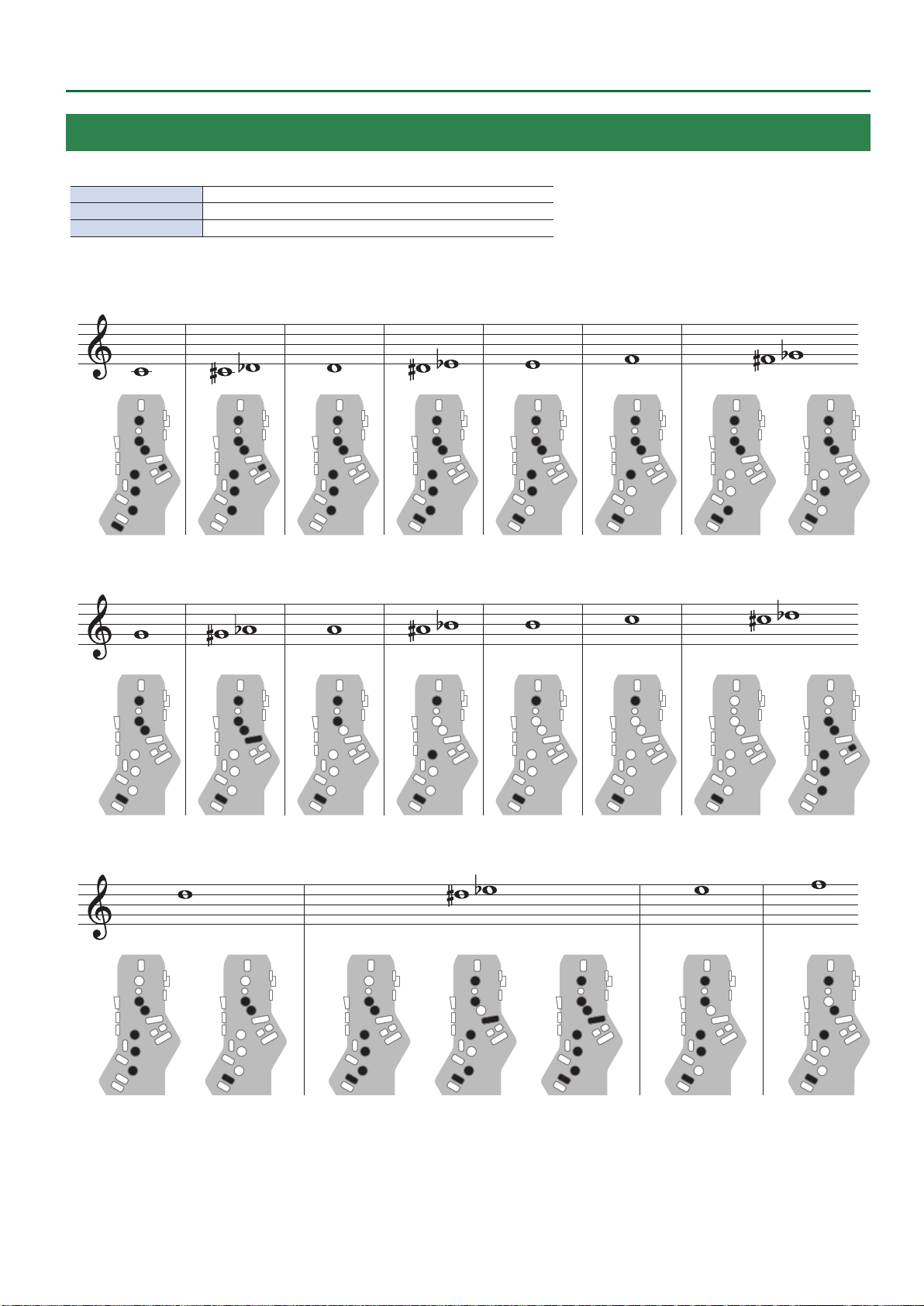
Flute
Flute ngering.
x, C1, C2, C3 Raise by a semitone
p, B, C4, Tc, Ta Lower by a semitone
Bb Lower by a whole tone
C4 D4 E4 F4C´4/D³4 D´4/E³4 F´4/G³4
Fingering Chart
G4 A4 B4 C5G´4/A³4 A´4/B³4 C´5/D³5
D5 E5 F5D´5/E³5
73

Fingering Chart
G5 A5F´5/G³5 G´5/A³5
B5 C6A´5/B³5
74

Clarinet
Clarinet ngering.
C1 Raise by a semitone
p, C5 Lower by a semitone
E3 F3 G3 A3F´3/G³3 G´3/A³3 A´3/B³3
Fingering Chart
B3 C4
F4 G4 A4F´4/G³4 A´4/B³4G´4/A³4
C´4/D³4 D´4/E³4
D4 E4
75

Fingering Chart
B4 C5 D5 E5 F5C´5/D³5 D´5/E³5
G5
C6 D6 E6C´6/D³6 D´6/E³6
A5 B5F´5/G³5 G´5/A³5 A´5/B³5
76
A6F6 G6F´6/G³6 G´6/A³6
 Loading...