

Page 1

Owner’s Manual
Bedienungsanleitung
Guide d’utilisation
Manuale dell'utente
Manual del usuario
Manual do proprietário
Gebruikershandleiding
Thank you, and congratulations on your choice of the Roland AC-90 Acoustic Chorus.
201b
Before using this unit, carefully read the sections entitled:
• IMPORTANT SAFETY INSTRUCTIONS (page 2)
• USING THE UNIT SAFELY (page 3–4)
• IMPORTANT NOTES (page 5)
These sections provide important information concerning the proper operation of the
unit. Additionally, in order to feel assured that you have gained a good grasp of every
feature provided by your new unit, Owner’s manual should be read in its entirety. The
manual should be saved and kept on hand as a convenient reference.
202
Copyright © 2007 ROLAND CORPORATION
All rights reserved. No part of this publication may be reproduced in any form without
the written permission of ROLAND CORPORATION.
Page 2
WARNING: To reduce the risk of fire or electric shock, do not expose this apparatus to rain or moisture.
CAUTION
RISK OF ELECTRIC SHOCK
DO NOT OPEN
ATTENTION: RISQUE DE CHOC ELECTRIQUE NE PAS OUVRIR
CAUTION: TO REDUCE THE RISK OF ELECTRIC SHOCK,
DO NOT REMOVE COVER (OR BACK).
NO USER-SERVICEABLE PARTS INSIDE.
REFER SERVICING TO QUALIFIED SERVICE PERSONNEL.
The lightning flash with arrowhead symbol, within an
equilateral triangle, is intended to alert the user to the
presence of uninsulated “dangerous voltage” within the
product’s enclosure that may be of sufficient magnitude to
constitute a risk of electric shock to persons.
The exclamation point within an equilateral triangle is
intended to alert the user to the presence of important
operating and maintenance (servicing) instructions in the
literature accompanying the product.
INSTRUCTIONS PERTAINING TO A RISK OF FIRE, ELECTRIC SHOCK, OR INJURY TO PERSONS.
IMPORTANT SAFETY INSTRUCTIONS
SAVE THESE INSTRUCTIONS
WARNING - When using electric products, basic precautions should always be followed, including the following:
1. Read these instructions.
2. Keep these instructions.
3. Heed all warnings.
4. Follow all instructions.
5. Do not use this apparatus near water.
6. Clean only with a dry cloth.
7. Do not block any of the ventilation openings. Install in
accordance with the manufacturers instructions.
8. Do not install near any heat sources such as radiators,
heat registers, stoves, or other apparatus (including
amplifiers) that produce heat.
9. Do not defeat the safety purpose of the polarized or
grounding-type plug. A polarized plug has two blades with
one wider than the other. A grounding type plug has two
blades and a third grounding prong. The wide blade or the
third prong are provided for your safety. If the provided plug
does not fit into your outlet, consult an electrician for
replacement of the obsolete outlet.
10. Protect the power cord from being walked on or pinched
particularly at plugs, convenience receptacles, and the
point where they exit from the apparatus.
11. Only use attachments/accessories specified by the
manufacturer.
12. Use only with the cart, stand, tripod, bracket,
or table specified by the manufacturer, or
sold with the apparatus. When a cart is used,
use caution when moving the cart/apparatus
combination to avoid injury from tip-over.
13. Unplug this apparatus during lightning storms or when
unused for long periods of time.
14. Refer all servicing to qualified service personnel. Servicing
is required when the apparatus has been damaged in any
way, such as power-supply cord or plug is damaged, liquid
has been spilled or objects have fallen into the apparatus,
the apparatus has been exposed to rain or moisture, does
not operate normally, or has been dropped.
For the U.K.
IMPORTANT: THE WIRES IN THIS MAINS LEAD ARE COLOURED IN ACCORDANCE WITH THE FOLLOWING CODE.
BLUE:
BROWN:
As the colours of the wires in the mains lead of this apparatus may not correspond with the coloured markings identifying
the terminals in your plug, proceed as follows:
The wire which is coloured BLUE must be connected to the terminal which is marked with the letter N or coloured BLACK.
The wire which is coloured BROWN must be connected to the terminal which is marked with the letter L or coloured RED.
Under no circumstances must either of the above wires be connected to the earth terminal of a three pin plug.
NEUTRAL
LIVE
2
Page 3
USING THE UNIT SAFELY
Used for instructions intended to alert
the user to the risk of death or severe
injury should the unit be used
improperly.
Used for instructions intended to alert
the user to the risk of injury or material
damage should the unit be used
improperly.
* Material damage refers to damage or
other adverse effects caused with
respect to the home and all its
furnishings, as well to domestic
animals or pets.
001
• Before using this unit, make sure to read the
instructions below, and the Owner’s Manual.
..........................................................................................................
002a
• Do not open or perform any internal modifications on the unit.
..........................................................................................................
003
• Do not attempt to repair the unit, or replace parts
within it (except when this manual provides
specific instructions directing you to do so). Refer
all servicing to your retailer, the nearest Roland Service
Center, or an authorized Roland distributor, as listed on
the “Information” page.
The symbol alerts the user to important instructions
or warnings.The specific meaning of the symbol is
determined by the design contained within the
triangle. In the case of the symbol at left, it is used for
general cautions, warnings, or alerts to danger.
The symbol alerts the user to items that must never
be carried out (are forbidden). The specific thing that
must not be done is indicated by the design contained
within the circle. In the case of the symbol at left, it
means that the unit must never be disassembled.
The ● symbol alerts the user to things that must be
carried out. The specific thing that must be done is
indicated by the design contained within the circle. In
the case of the symbol at left, it means that the powercord plug must be unplugged from the outlet.
010
• This unit, either alone or in combination with an
amplifier and headphones or speakers, may be
capable of producing sound levels that could
cause permanent hearing loss. Do not operate for
a long period of time at a high volume level, or at
a level that is uncomfortable. If you experience
any hearing loss or ringing in the ears, you should
immediately stop using the unit, and consult an
audiologist.
...........................................................................................................
011
• Do not allow any objects (e.g., flammable material,
coins, pins); or liquids of any kind (water, soft
drinks, etc.) to penetrate the unit.
..........................................................................................................
004
• Never use or store the unit in places that are:
• Subject to temperature extremes (e.g., direct
sunlight in an enclosed vehicle, near a heating
duct, on top of heat-generating equipment); or
are
• Damp (e.g., baths, washrooms, on wet floors); or are
• Humid; or are
• Exposed to rain; or are
• Dusty; or are
• Subject to high levels of vibration.
..........................................................................................................
008a
• The unit should be connected to a power supply
only of the type described in the operating
instructions, or as marked on the rear side of unit.
..........................................................................................................
009
• Do not excessively twist or bend the power cord,
nor place heavy objects on it. Doing so can
damage the cord, producing severed elements
and short circuits. Damaged cords are fire and shock
hazards!
..........................................................................................................
...........................................................................................................
012a
• Immediately turn the power off, remove the
power cord from the outlet, and request servicing
by your retailer, the nearest Roland Service
Center, or an authorized Roland distributor, as listed on
the “Information” page when:
• The power-supply cord or the plug has been damaged;
or
• If smoke or unusual odor occurs
• Objects have fallen into, or liquid has been spilled onto
the unit; or
• The unit has been exposed to rain (or otherwise has
become wet); or
• The unit does not appear to operate normally or
exhibits a marked change in performance.
...........................................................................................................
013
• In households with small children, an adult
should provide supervision until the child is
capable of following all the rules essential for the
safe operation of the unit.
...........................................................................................................
014
• Protect the unit from strong impact.
(Do not drop it!)
...........................................................................................................
3
Page 4
015
• Do not force the unit’s power-supply cord to
share an outlet with an unreasonable number of
other devices. Be especially careful when using
extension cords—the total power used by all
devices you have connected to the extension
cord’s outlet must never exceed the power rating
(watts/amperes) for the extension cord. Excessive
loads can cause the insulation on the cord to heat
up and eventually melt through.
..........................................................................................................
016
• Before using the unit in a foreign country, consult
with your retailer, the nearest Roland Service
Center, or an authorized Roland distributor, as
listed on the “Information” page.
..........................................................................................................
026
• Do not put anything that contains water (e.g.,
flower vases) on this unit. Also, avoid the use of
insecticides, perfumes, alcohol, nail polish, spray
cans, etc., near the unit. Swiftly wipe away any
liquid that spills on the unit using a dry, soft
cloth.
..........................................................................................................
101a
• The unit should be located so that its location or
position does not interfere with its proper ventilation.
...........................................................................................................
102a
• Always grasp only the plug on the power-supply
cord when plugging into, or unplugging from an
outlet.
...........................................................................................................
103a
• At regular intervals, you should unplug the
power plug and clean it by using a dry cloth to
wipe all dust and other accumulations away from
its prongs. Also, disconnect the power plug from
the power outlet whenever the unit is to remain
unused for an extended period of time. Any
accumulation of dust between the power plug and
the power outlet can result in poor insulation and
lead to fire.
...........................................................................................................
104
• Try to prevent cords and cables from becoming
entangled. Also, all cords and cables should be
placed so they are out of the reach of children.
...........................................................................................................
106
• Never climb on top of, nor place heavy objects on
the unit.
...........................................................................................................
107a
• Never handle the power cord or its plug with wet
hands when plugging into, or unplugging from,
an outlet.
...........................................................................................................
108a
• Before moving the unit, disconnect the power
plug from the outlet, and pull out all cords from
external devices.
...........................................................................................................
109a
• Before cleaning the unit, turn off the power and
unplug the power cord from the outlet.
...........................................................................................................
110a
• Whenever you suspect the possibility of lightning
in your area, pull the plug on the power cord out
of the outlet.
...........................................................................................................
120
• Always turn the phantom power off when
connecting any device other than condenser
microphones that require phantom power. You
risk causing damage if you mistakenly supply
phantom power to dynamic microphones, audio
playback devices, or other devices that don’t
require such power. Be sure to check the specifications of any microphone you intend to use by
referring to the manual that came with it.
4
(This instrument’s phantom power: 48 V DC, 10 mA Max)
...........................................................................................................
Page 5

IMPORTANT NOTES
291b
In addition to the items listed under “IMPORTANT SAFETY INSTRUCTIONS” and “USING THE UNIT SAFELY” on pages 2
and 4, please read and observe the following:
Power Supply
301
• Do not connect this unit to same electrical outlet that is being
used by an electrical appliance that is controlled by an inverter
(such as a refrigerator, washing machine, microwave oven, or air
conditioner), or that contains a motor. Depending on the way in
which the electrical appliance is used, power supply noise may
cause this unit to malfunction or may produce audible noise. If it
is not practical to use a separate electrical outlet, connect a power
supply noise filter between this unit and the electrical outlet.
307
• Before connecting this unit to other devices, turn off the power to
all units. This will help prevent malfunctions and/or damage to
speakers or other devices.
308
• Although the LEDs are switched off when the POWER switch is
switched off, this does not mean that the unit has been completely
disconnected from the source of power. If you need to turn off the
power completely, first turn off the POWER switch, then unplug
the power cord from the power outlet. For this reason, the outlet
into which you choose to connect the power cord’s plug should
be one that is within easy reach and readily accessible.
Placement
351
• Using the unit near power amplifiers (or other equipment
containing large power transformers) may induce hum. To
alleviate the problem, change the orientation of this unit; or move
it farther away from the source of interference.
352a
• This device may interfere with radio and television reception. Do
not use this device in the vicinity of such receivers.
352b
• Noise may be produced if wireless communications devices, such
as cell phones, are operated in the vicinity of this unit. Such noise
could occur when receiving or initiating a call, or while
conversing. Should you experience such problems, you should
relocate such wireless devices so they are at a greater distance
from this unit, or switch them off.
354b
• Do not expose the unit to direct sunlight, place it near devices
that radiate heat, leave it inside an enclosed vehicle, or otherwise
subject it to temperature extremes. Also, do not allow lighting
devices that normally are used while their light source is very
close to the unit (such as a piano light), or powerful spotlights to
shine upon the same area of the unit for extended periods of time.
Excessive heat can deform or discolor the unit.
355b
• When moved from one location to another where the temperature
and/or humidity is very different, water droplets (condensation)
may form inside the unit. Damage or malfunction may result if
you attempt to use the unit in this condition. Therefore, before
using the unit, you must allow it to stand for several hours, until
the condensation has completely evaporated.
356
• Do not allow rubber, vinyl, or similar materials to remain on the
unit for long periods of time. Such objects can discolor or
otherwise harmfully affect the finish.
359
• Do not paste stickers, decals, or the like to this instrument.
Peeling such matter off the instrument may damage the exterior
finish.
360
• Depending on the material and temperature of the surface on
which you place the unit, its rubber feet may discolor or mar the
surface.
You can place a piece of felt or cloth under the rubber feet to
prevent this from happening. If you do so, please make sure that
the unit will not slip or move accidentally.
Add
• Do not allow objects to remain on top of the unit while it is in
operation.
• Do not sit or lean on top of the unit.
Maintenance
401a
• For everyday cleaning wipe the unit with a soft, dry cloth or one
that has been slightly dampened with water. To remove stubborn
dirt, use a cloth impregnated with a mild, non-abrasive detergent.
Afterwards, be sure to wipe the unit thoroughly with a soft, dry
cloth.
402
• Never use benzine, thinners, alcohol or solvents of any kind, to
avoid the possibility of discoloration and/or deformation.
Additional Precautions
553
• Use a reasonable amount of care when using the unit’s buttons,
sliders, or other controls; and when using its jacks and
connectors. Rough handling can lead to malfunctions.
556
• When connecting / disconnecting all cables, grasp the connector
itself—never pull on the cable. This way you will avoid causing
shorts, or damage to the cable’s internal elements.
557
• A small amount of heat will radiate from the unit during normal
operation.
558a
• To avoid disturbing your neighbors, try to keep the unit’s volume
at reasonable levels. You may prefer to use headphones, so you
do not need to be concerned about those around you (especially
when it is late at night).
559a
• When you need to transport the unit, package it in the box
(including padding) that it came in, if possible. Otherwise, you
will need to use equivalent packaging materials.
562
• Some connection cables contain resistors. Do not use cables that
incorporate resistors for connecting to this unit. The use of such
cables can cause the sound level to be extremely low, or impossible to hear. For information on cable specifications, contact the
manufacturer of the cable.
921
• To prevent malfunction and/or damage to speakers or other
devices, always turn down the volume, and turn off the power on
all devices before making any connections.
922
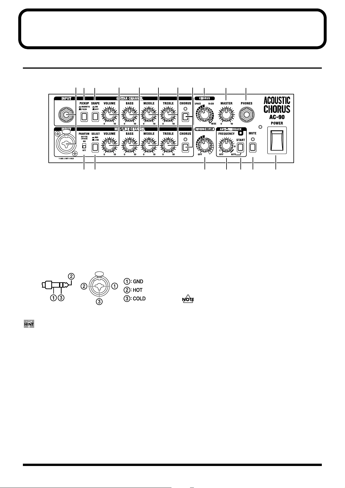
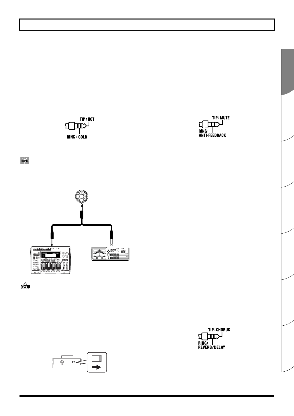
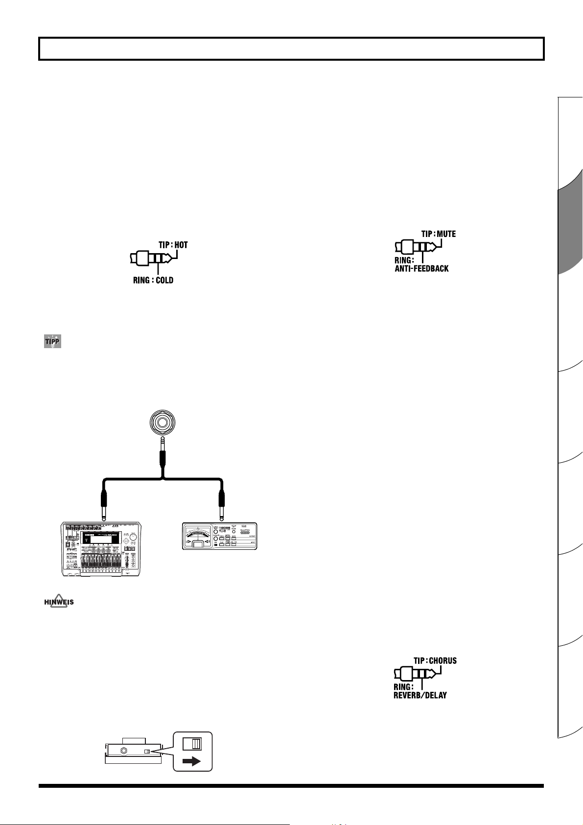
• This instrument is equipped with balanced XLR/TRS type jacks.
Wiring diagrams for these jacks are shown below. Make connections after first checking the wiring diagrams of other equipment
you intend to connect.
fig.XLR/TRSJack.eps
941
• Once the connections have been completed (p. 11), turn on power
to your various devices in the order specified. By turning on
devices in the wrong order, you risk causing malfunction and/or
damage to speakers and other devices.
When powering up:
Turn on the power to the AC-90 last.
When powering down:
Turn off the power to the AC-90 first.
Add
• Wrap the AC cord around the cord hook when trans-porting or
storing the unit.
5
Page 6

Contents
USING THE UNIT SAFELY ............................................3
IMPORTANT NOTES ......................................................5
Contents..............................................................................6
English
Main Features.........................................................7
Names of Things and What They Do .................8
Control Panel...............................................8
Rear Panel..................................................12
Example of Using Two Channels Combined...14
How to Use the Folding Stand...........................15
Using a Speaker Stand ........................................16
Deutsch
Hauptmerkmale...................................................17
Bezeichnungen und Funktionen der
Bedienelemente....................................................18
Bedienfeld..................................................18
Rückseite....................................................22
Beispiel für die kombinierte Verwendung
zweier Kanäle.......................................................24
Verwendung des ausklappbaren Bügels..........25
Verwenden eines Lautsprecherstativs..............26
Español
Principales características...................................47
Nombres de componentes y sus funciones......48
Panel de control ........................................48
Panel trasero..............................................52
Ejemplo de uso de dos canales combinados....54
Cómo utilizar el soporte plegable .....................55
Utilización de un soporte de altavoz ................56
Português
Principais características.....................................57
Nomes das partes e suas funções ......................58
Painel de controle .....................................58
Painel traseiro............................................62
Exemplo de uso de dois canais combinados....64
Como utilizar o suporte dobrável .....................65
Utilizando um suporte para alto-falante..........66
Nederlands
Belangrijkste kenmerken.....................................67
Namen van onderdelen en hun functies ..........68
Voorpaneel ................................................68
Achterpaneel .............................................72
Français
Caractéristiques principales...............................27
Noms et fonctions des éléments ........................28
Panneau de commande ...........................28
Panneau arrière.........................................32
Exemple d’utilisation de deux canaux
ensemble................................................................34
Utilisation du pied pliant....................................35
Utilisation d’un pied pour haut-parleur ..........36
Italiano
Caratteristiche principali ....................................37
Denominazione e utilizzo delle funzioni .........38
Pannello di controllo................................38
Pannello posteriore ..................................42
Esempio di utilizzo di due canali combinati ...44
Modalità di utilizzo del supporto pieghevole.45
Utilizzo di un supporto casse.............................46
Voorbeeld van gecombineerd gebruik van
twee kanalen.........................................................74
De vouwstandaard gebruiken ...........................75
Een luidsprekerstandaard gebruiken ...............76
Block Diagram .................................................................77
How to Use the Carrying Case......................................77
Specifications ...................................................................78
6
Page 7

Main Features
The AC-90 is a high-performance monitor amp developed exclusively for use with acoustic instruments. It is capable of faithfully
expressing all the harmonic richness of an acoustic instrument’s sound.
Compact, High-Performance Stereo
Amp
• The finely tuned design of the cabinet is meant to
enhance the sound of acoustic instruments. Within this
cabinet, there are two 8 inch woofers, two tweeters, and
a 45 W + 45 W stereo amp—all of which were newly
designed just for the AC-90. As a result, the unit is
capable of delivering a more natural, acoustic instrument
sound across a broad range of frequencies.
• Thanks to a power amp that was designed to be as light
as possible, and the use of new materials for the woofers,
an overall reduction in the weight of the unit has been
achieved.
Features Two Independent Channels,
GUITAR and MIC/LINE
• Each channel includes a 3-band equalizer.
• GUITAR channel handles both piezo and magnetic
pickups.
• The MIC/LINE channel offers phantom power,
produced by highly reliable, dedicated 48 V output
phantom circuitry.
• Using the MIC/LINE channel for LINE input allows you
to connect guitars with magnetic pickups. You can also
use a piezo pickup (GUITAR channel) and a magnetic
pickup (MIC/LINE channel) at the same time, and mix
(blend) the sounds together.
High-Quality Digital Effects
• Three kinds of stereo chorus effects are provided. There
is the spatially synthesized “SPACE” chorus, the “RICH”
chorus (which is divided into frequency bands), and the
“WIDE” chorus (which is also divided into frequency
bands while offering even greater expansiveness).
• Includes stereo reverb developed especially for acoustic
instruments. This allows you to add a sense of
spaciousness and natural body to the sound.
• Equipped with delay effects that can produce sound
with a tonal quality that is soft and tuned specifically for
acoustic instruments.
• An optional foot switch can also be used to turn the
effects on and off.
Mute Function
• The provided Mute switch makes it easy for you to mute
the sounds for the AC-90’s own speakers as well as the
sounds from LINE OUT. By using the Mute function,
you can plug in and out noiselessly at the guitar.
Furthermore, when you have a tuner connected to
TUNER OUT, the Mute function lets you tune your
instrument without outputting any sound.
• You can connect an optional foot switch and use your
foot to turn this on and off.
External Input Jacks (AUX IN)
• Includes external input jacks, allowing you to connect a
CD player, backing machine, or other device in stereo.
•These include both RCA phono jacks and 1/4” phone
jacks, making it possible to connect just about any kind
of device.
Multiple Output Connectors
• Features DI Out, which allow you to directly output the
signals input from connected instruments and mics. You
can also connect a tuner. TRS balanced output is
supported.
• Line outs feature 1/4” phone mono-output jacks in
addition to XLR connectors for stereo output. You can
use a single AC-90 for all applications.
• It also features a Subwoofer Out. Connecting a powered
subwoofer allows you to play with an even punchier,
more powerful low end.
• The amp also provides a headphones jack, which you
can use when playing during nighttime hours and when
making sound checks.
Convenient Placement Features
• Equipped with a “folding stand,” which allows you to
change the angle of the amp when using it for
monitoring purposes.
• Includes a “speaker stand adapter,” which allows you to
attach the AC-90 to a speaker stand. This makes using
the AC-90 easier when you are performing standing up,
and allows you to use the amp as a simple PA.
• Also included is a carrying case for greater portability.
Español Italiano Français Deutsch EnglishPortuguêsNederlands
Anti-Feedback Suppresses Feedback
• Anti-feedback features two ways to detect the feedback
point. You can use the “Manual settings,” or you can use
the “Auto settings,” which provide for the automatic
detection of the feedback point.
• You can connect an optional foot switch and use your
foot to operate this feature.
7
Page 8
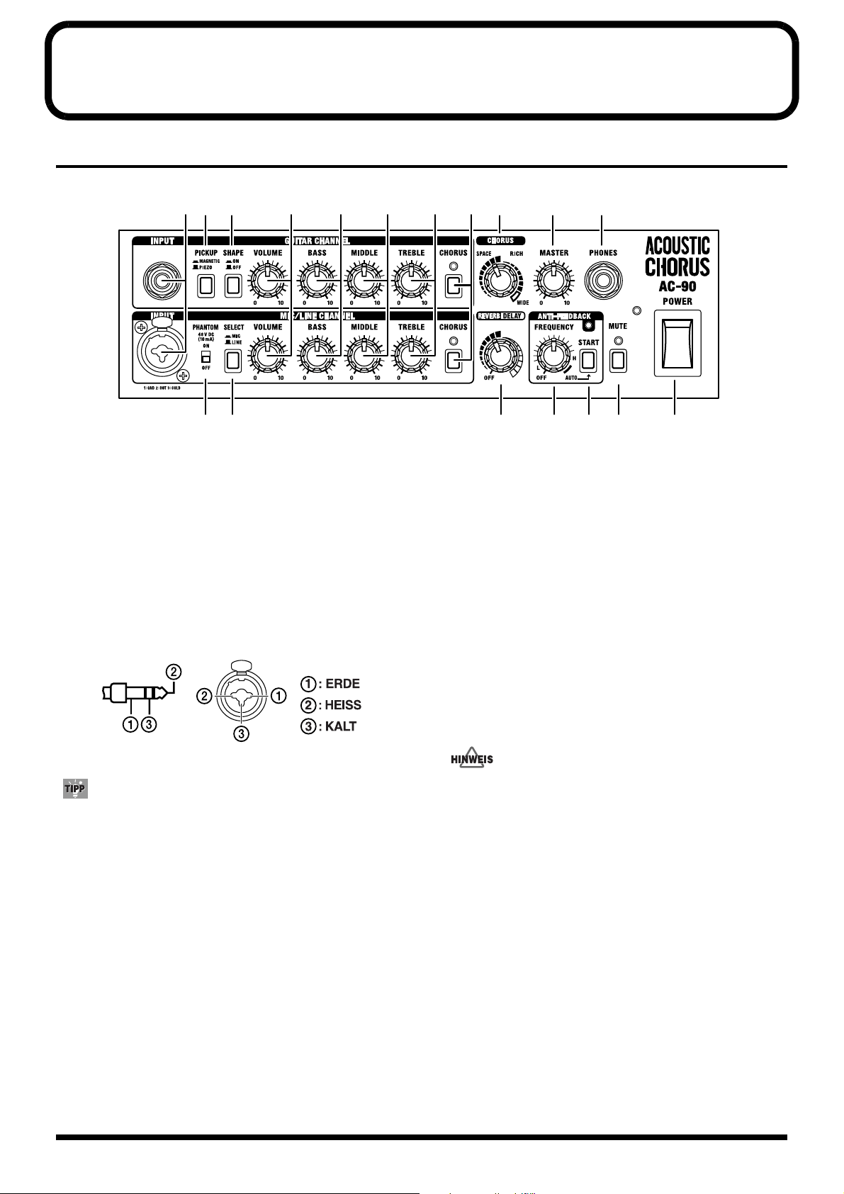
Names of Things and What They Do
Control Panel
fig.010
12 3
45
1. INPUT
(GUITAR CHANNEL)
Connect guitars here.
(MIC/LINE CHANNEL)
Connect mics and line-level devices here. You can also
connect guitars with pickups equipped with preamps.
This handles balanced input, so you can connect 1/4” phone
TRS jacks and XLR-type connectors.
fig.030
10 11 16 17
9678
12 13 14 15 18
3. SHAPE Button
Setting this to ON modifies the midrange to create a bright
tone suitable for strumming chords.
This emphasizes brushing sounds, allowing you to strum
with a more edgy feeling.
4. PHANTOM Switch
This turns the phantom power on and off.
Set this to “ON” when connecting mics that require phantom
power (condenser mic, etc.).
Set this to “OFF” when connecting mics that do not require
phantom power or other devices.
XLRTRS
You can use the two channels in combination.
Refer to “Example of Using Two Channels Combined” (p. 14).
983
* Feedback could be produced depending on the location of
microphones relative to speakers. This can be remedied by:
•Changing the orientation of the microphone(s).
•Relocating microphone(s) at a greater distance from speakers.
•Lowering volume levels.
2. PICKUP Button
This switches the input circuitry for either piezo or magnetic
pickups, according to the type of pickup on the connected
guitar. Press down the button for magnetic pickups.
* Set this to “MAGNETIC” if your guitar has an active pickup
equipped with a preamp.
8
• Use the following sequence when connecting mics that
require phantom power:
1.Turn the PHANTOM switch off.
2.Connect the mic.
3.Turn the PHANTOM switch on.
• Supplying phantom power to mics that do not require it
or supplying it to other devices may cause such
equipment to malfunction. Always be sure to turn the
switch off before connecting.
* To protect the circuitry, all output is muted momentarily after
the PHANTOM switch is turned on or off.
* Phantom power is supplied only to the XLR connectors for the
MIC/LINE channel INPUT.
* Noise may be produced if connectors are connected or
disconnected while the phantom power is turned on.
Page 9
Names of Things and What They Do
Phantom Power
Because they have a comparatively wider range and better
sound quality than dynamic mics, condenser mics are often
used for miking acoustic guitars. However, they require a
power source to operate. Although some condenser mics run
off batteries placed within the mic housing, in many cases a
type of power supply known as “phantom power” is
required. This power supply uses the existing mic cable to
feed power.
The AC-90’s phantom power is output at a constant 48 V, so
it conforms to professional specifications required at
recording studios.
5. SELECT Button
This switches the input level to match that of the connected
device (mic or line).
You can connect guitars with magnetic pickups when LINE
is selected with the SELECT button.
* Note that the volume is increased if the switch is set to “MIC”
when you have a line-level device connected.
9. TREBLE Knobs
Adjust the level of the high-frequency range.
The tone of an acoustic instrument can vary immensely from
one instrument to the next. The kind of sound required also
varies according to how an instrument is being used in a
particular ensemble. Actively use the BASS, MIDDLE, and
TREBLE knobs to adjust the tone to suit the instrument you
are using and the conditions in which it is being used.
(Example)
• When using the AC-90 with the speaker stand attached,
you may want to turn up the BASS knob so the lower
range is perceived better.
• If the sound seems too harsh, such as immediately after
changing strings, you may want to turn down the
TREBLE knob to cut back on the high frequencies.
10. CHORUS Buttons
Switch chorus on and off.
When on, the indicator is lit.
6. VOLUME Knobs
(GUITAR CHANNEL)
Adjusts the volume of the GUITAR channel.
* To accommodate the lower output of piezo pickups, the volume
level when the VOLUME knob is between the 7 and 10
positions is set somewhat higher when the PICKUP button is
set to PIEZO in comparison with the MAGNETIC setting.
(MIC/LINE CHANNEL)
Adjusts the volume of the MIC/LINE channel.
* When using the AC-90 with the GUITAR channel and MIC/
LINE channel mixed, adjust the volume balance between the
two channels with the VOLUME knob.
7. BASS Knobs
Adjust the level of the low-frequency range.
8. MIDDLE Knobs
Adjust the level of the midrange.
You can use a foot switch (the optional BOSS FS-5U) to
switch chorus on and off. Turning chorus on and off with the
foot switch works on both channels.
11. CHORUS Knob
Turn this knob to select among the three types of chorus
(SPACE, RICH, and WIDE).
You can adjust the amount of effect applied by changing the
position of the knob.
* This is enabled when the CHORUS button is in the ON
position.
* The markings indicating the SPACE and RICH positions are
approximate. Listen to the sound to confirm the effect as you
make adjustments.
SPACE
This is a spacially synthesized chorus. With spacially
synthesized chorus, a method available only in stereo, the
chorus effect is created by taking the sound from the right
speaker (from which the effect sound is output), and the
sound from the left speaker (which outputs the direct sound),
and then mixing them in the actual space. This creates a
greater lateral spread than that produced when the sounds
are mixed electronically, providing a more natural sense of
breadth.
Español Italiano Français Deutsch EnglishPortuguêsNederlands
9
Page 10
Names of Things and What They Do
RICH
This is a stereo chorus that is divided into three frequency
ranges.
Here, the effect is separated into three bands, low-frequency,
midrange, and high-frequency, and by applying the most
suitable amount of chorus effect in each range, it provides a
sense of fullness and breadth that is perfectly suited to the
acoustic guitar.
The low end is firmly in the center, and sound spreads out
more and more as the sound rises from the midrange up
through the higher frequencies.
WIDE
While also relying on the division of sound into separate
bands, this chorus offers even greater expansiveness than
RICH.
The sound image spreads beyond the AC-90’s speakers,
producing an effect that seems to envelope the listener in
sound.
12. REVERB/DELAY Knob
You can adjust this knob to switch between the reverb and
delay effects.
You can adjust the amount of effect applied by changing the
position of the knob.
* Turn the knob to “OFF” if you are not using the reverb or
delay effect.
* The markings indicating the reverb and delay positions are
approximate. Listen to the sound to confirm the effect as you
make adjustments.
REVERB
This stereo reverb, developed especially for acoustic
instruments, gives a sense of spaciousness and natural sonic
quality.
Turn the knob to adjust the volume of the reverb effect.
DELAY
This delay, developed especially for acoustic instruments,
adds soft reflections to the original sound.
Turn the knob to change the delay time.
* You can use a foot switch (the optional BOSS FS-5U) to
switch the reverb and delay on and off.
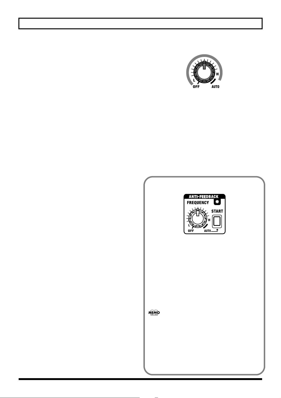
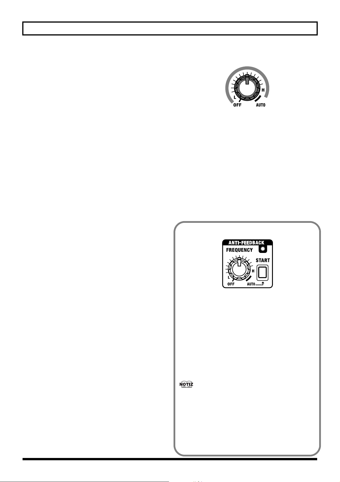
13. FREQUENCY Knob
This selects the frequency at which the anti-feedback
function operates.
Also, the position of the knob determines whether Auto or
Manual settings are selected.
fig.031
MANUAL
* Turn the knob to “OFF” if you are not using anti-feedback.
14. START Button
This is used for Auto settings (p. 11). Pressing the button
performs automatic detection of feedback-whine frequencies.
The indicators show the operating status of the automatic
detection function.
Standby: Flashes slowly
During Detection: Flashes rapidly
After Detection: Remains lit
* Holding down the START button for one second or longer
returns the unit to standby for automatic detection.
How to Use ANTI-FEEDBACK
fig.32
Anti-feedback is a function that controls feedback that arises
between the guitar or mic and the amp.
The feedback is suppressed by attenuating the frequency at
which the feedback occurs.
* This is not designed to work with respect to the high-frequency
feedback that can occur when using microphones.
Anti-feedback can be used in two different ways; you can
make use of either the “Auto settings” or the “Manual
settings.”
* Use either when feedback whine occurs.
Feedback
This is a phenomenon whereby signals output from the
speakers are picked up again by the mic or pickup, and the
sound is further amplified and output from the speakers,
resulting in an unpleasant oscillating sound.
* If the anti-feedback alone does not control the feedback, adjust
your settings, for example by lowering the volume or cutting
the low frequencies.
* To prevent feedback during a performance, we recommend
making the anti-feedback setting before the performance.
10
Page 11
Names of Things and What They Do
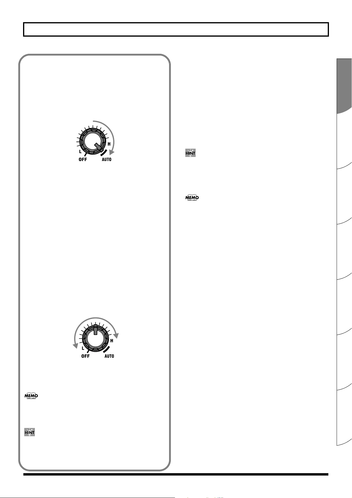
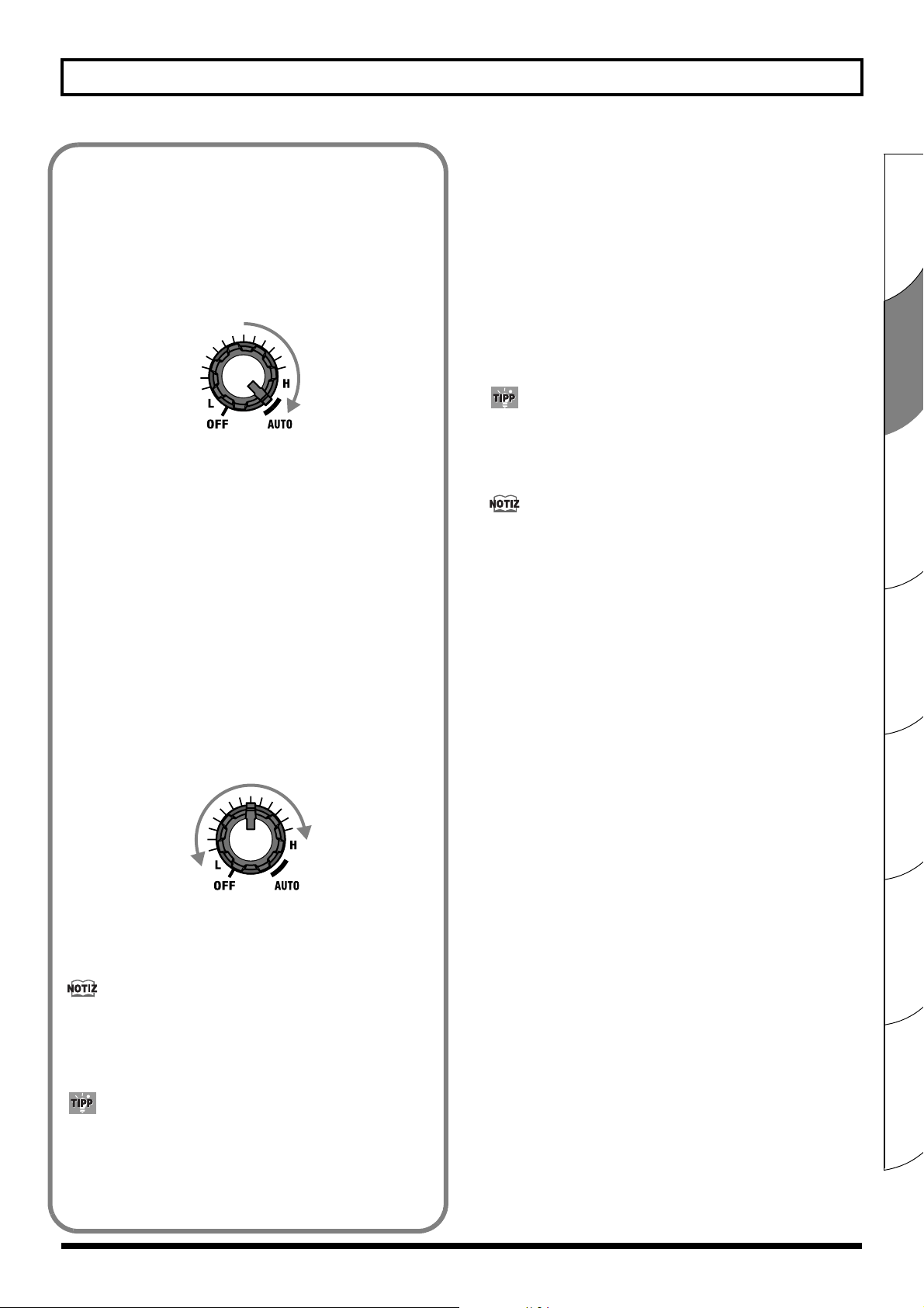
Setting the Feedback Point Automatically
This automatically detects the frequency at which feedback
occurs and suppresses feedback.
* Use in conditions where feedback occurs.
1. Cause feedback whine to occur.
2. Turn the FREQUENCY knob to the “AUTO” position.
fig.033
The ANTI-FEEDBACK indicator flashes slowly, and
automatic detection goes into standby.
3. Press the START button.
Automatic detection of the feedback point starts. The indicator
flashes rapidly when detection is in progress, and when the
feedback point is found, the indicator lights steadily. If no
feedback point is detected, the indicator flashes slowly, and
the automatic detection function returns to standby.
4. Press the START button once more to conduct the
automatic detection again.
15. MUTE Button
This switches the Mute function on and off.
When you press the button, the MUTE indicator flashes,
muting is turned on, and the speaker output and sounds
from SUB WOOFER OUT and LINE OUT are muted.
With the mute function activated, you do not need to turn
down the VOLUME knob or MASTER knob to mute the
noise when plugging into, or unplugging from your guitar.
* Sounds from the DI OUT/TUNER OUT and PHONES jacks
are not muted.
By connecting a tuner (optional) to DI OUT/TUNER OUT
and then pressing the MUTE button, you can tune your
instrument without the sound being output from the
speakers.
You can use a foot switch (optional BOSS FS-5U or FS-6) to
switch muting on and off. (p. 13)
16. MASTER Knob
Adjusts the overall volume level.
* LINE OUT cannot be adjusted.
Setting the Feedback Point Manually
1. Cause feedback whine to occur.
2. Turn the knob, moving through the range of L through
H (the ANTI-FEEDBACK indicator lights up) to search
for the frequency at which the feedback is to be
suppressed.
fig.34
Turning the knob clockwise suppresses progressively more
treble feedback, and turning it counterclockwise suppresses
progressively more bass feedback.
You can use a foot switch (the optional BOSS FS-5U, FS-6) to
run automatic detection of the feedback frequency or to turn
the anti-feedback function on and off.
17. PHONES Jack
Headphones are connected here. No sounds are output from
the speakers or from SUB WOOFER OUT when headphones
are connected.
18. POWER Switch
This turns the AC-90’s power on and off.
The POWER indicator lights up when the power is on.
945
* If you need to turn off the power completely, first turn off the
POWER switch, then unplug the power cord from the power
outlet. Refer to Power Supply (p. 5)
942
* Due to a circuitry protection feature, this unit requires a few
moments after it has been turned on before it is ready for
normal operation.
943
* Always make sure to have the volume level turned down before
switching on power. Even with the volume all the way down,
you may still hear some sound when the power is switched on,
but this is normal, and does not indicate a malfunction.
Español Italiano Français Deutsch EnglishPortuguêsNederlands
You can use anti-feedback even when feedback is not a
problem. For example, you can use it to remove undesirable
resonance in the low to midrange, as well as correct other
problems with the sound quality.
11
Page 12
Names of Things and What They Do
k
Rear Panel
fig.040
5431 2
*
PCS-31
White Red
Drum Machine
Powered
Sub Woofer
926a
When connection cables with resistors are used, the volume level of equipment connected to the inputs may be low.
*
If this happens, use connection cables that do not contain resistors.
Mixer
Recorder
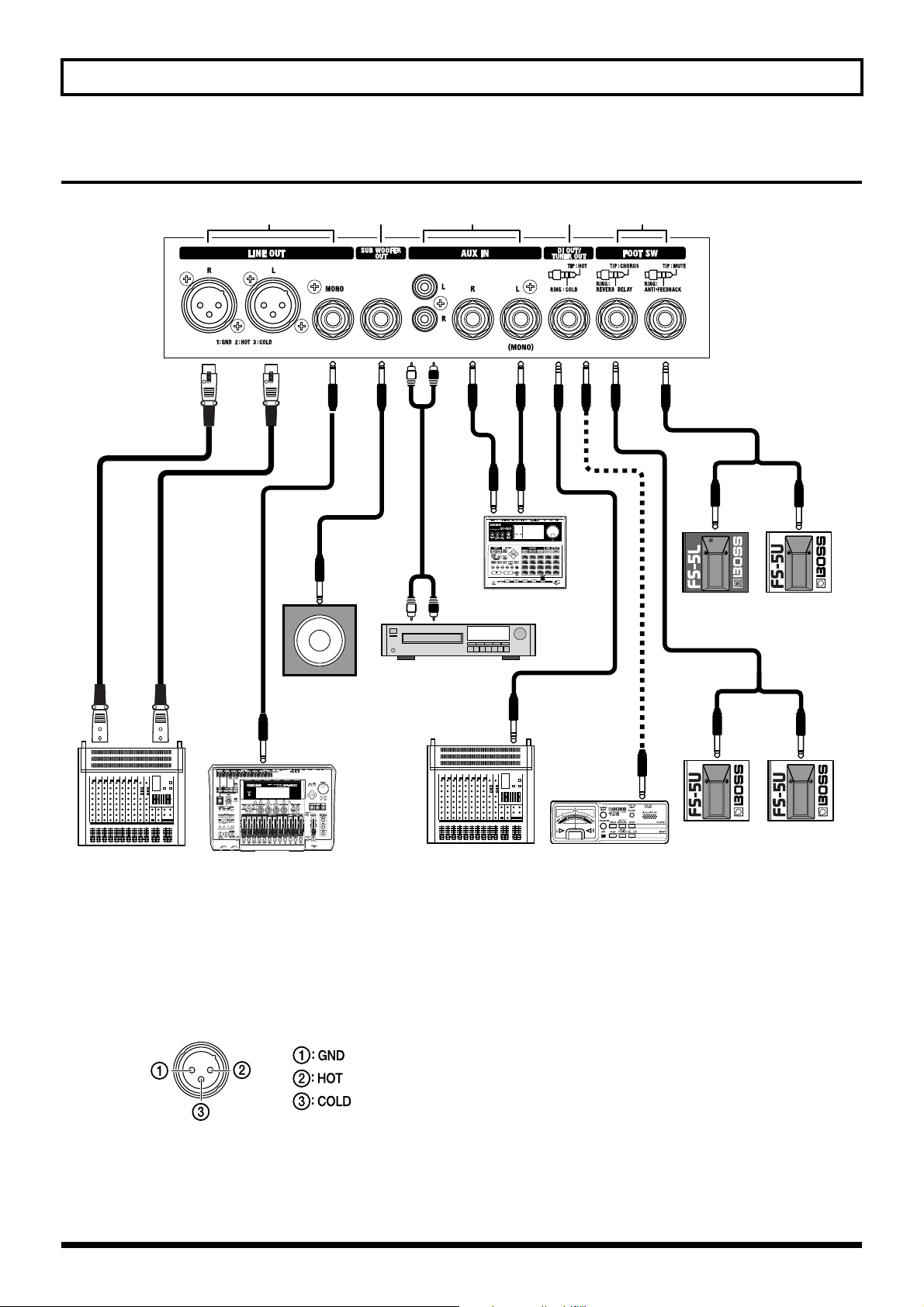
1. LINE OUT Jacks
You can connect a mixer, recording device, or other device
here. The output level is +4 dBu.
Included here are XLR connectors (L/R: stereo output) and a
1/4” phone jack (mono output).
fig.090
* You cannot adjust the volume for LINE OUT with the
MASTER knob.
* The chorus effects are designed so they exhibit the greatest
effectiveness when you use the unit’s built-in speakers.
Effectiveness may differ when LINE OUT is used instead of
the built-in speakers.
CD Player
Mixer
Tuner
2. SUB WOOFER OUT Jack
You can connect a powered subwoofer to play back sounds
with an even punchier, more powerful low end.
The volume is adjusted with the MASTER knob.
3. AUX IN Jacks
You can connect a CD player, drum machine, or other device
and play back sounds in stereo. Both RCA phono jacks and
1/4” phone jacks are provided. When connected to only the
left 1/4” phone jack, playback is in mono.
Although the input from AUX IN is output from the
speakers, PHONES, and SUB WOOFER OUT, it is not output
from LINE OUT. The volume is adjusted with the MASTER
knob, and muting on/off for these sounds is controlled with
Mute On/Off
White Red
Chorus
On/Off
Anti-Feedbac
PCS-31
Reverb/Delay
On/Off
12
Page 13
Names of Things and What They Do
the MUTE button.
If devices are connected to both the RCA phono jacks and the
1/4” phone jacks, the two inputs are mixed.
4. DI OUT/TUNER OUT Jack
The direct sound of the device or instrument connected to the
GUITAR or MIC/LINE channel is output here. This is a 1/4”
phone TRS jack with balanced output.
You can also use this jack to connect a tuner.
fig.070
* If balanced output is not required, use a 1/4” phone (mono)
plug to connect to this jack.
If balanced output is not required, you can use the special
connection cable (the optional PCS-31) to use the DI OUT and
TUNER OUT simultaneously.
fig.080
PCS-31
White Red
Tuner
Recoreder
(MUTE, ANTI-FEEDBACK)
Connecting a foot switch pedal (optional BOSS FS-5L, FS-5U,
or FS-6) using a connection cable (the optional PCS-31) makes
it possible to use a latch-type foot switch (the FS-5L or FS-6)
to switch muting on and off, or to use a momentary-type foot
switch (the FS-5U or FS-6) to control the anti-feedback
feature.
* For information on the settings for the FS-6, refer to the
owner’s manual for the FS-6.
fig.050
When a 1/4” phone (mono) plug is used to connect only one
foot switch, only the Mute on/off function is enabled. In such
cases, you should use a latch-type foot switch pedal (such as
the BOSS FS-5L)
* The MUTE button should be set to off when a foot switch is
connected for muting.
You cannot switch the muting off by pressing the foot switch
when the MUTE button is on (when the MUTE indicator is
lit).
* When using an FS-5U (momentary type) to switch muting on
and off, the muting is switched on only while the switch is held
down.
For anti-feedback, a foot switch will function as follows:
• When the FREQUENCY knob is positioned in the range
from L to H, the switch turns the anti-feedback function
on and off.
• When the FREQUENCY knob is positioned at AUTO, the
switch functions as the START switch for the automatic
detection. Holding the foot switch down for one second
or longer returns the automatic detection function to
standby mode.
Español Italiano Français Deutsch EnglishPortuguêsNederlands
A phase-inverted signal is output from the COLD side (the
red side of the PCS-31). Connect the recording device to the
HOT side (the white side of the PCS-31)
5. FOOT SW Jacks
The AC-90 accepts the BOSS FS-5L (latch type), BOSS FS-5U
(momentary type), and BOSS FS-6 foot switch pedals.
* Set the polarity switch as shown below.
fig.071
(CHORUS, DELAY/REVERB)
Using a special connection cable (the optional PCS-31) to
connect two foot switches (the optional BOSS FS-5U), you
can use one FS-5U to switch the chorus on and off, and use
the other FS-5U to switch the delay or reverb on and off.
fig.060
When a 1/4” phone (mono) plug is used to connect only one
foot switch, only the chorus on/off function is enabled.
* The chorus on/off function works on both channels.
* You cannot switch the chorus on and off by pressing the foot
switch when the CHORUS button is off.
13
Page 14
Example of Using Two Channels Combined
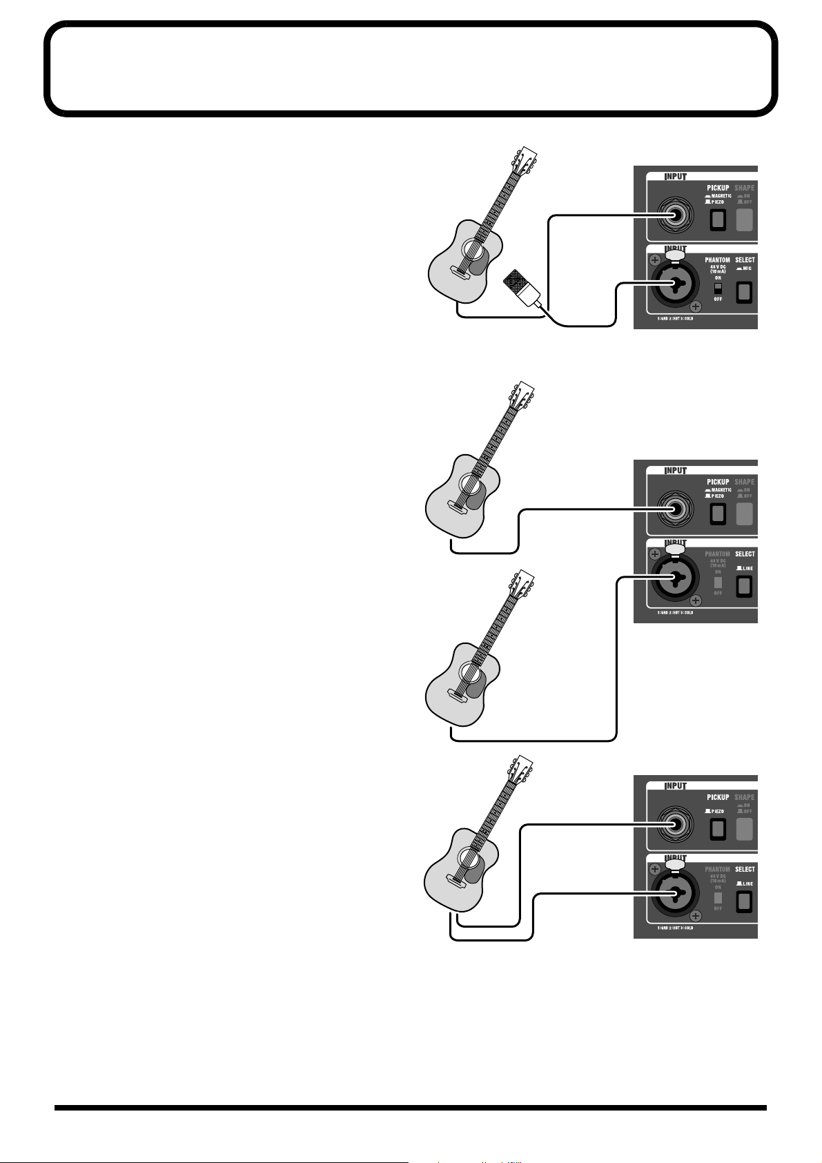
When Using a Mic and a Pickup
GUITAR CHANNEL:
Piezo or Magnetic Pickup
MIC/LINE CHANNEL:
Condenser or Dynamic mic (SELECT button = MIC)
This allows you to blend the fat midrange of the pickup with the
mic’s delicate high end.
Set the PHANTOM switch to ON if using a condenser mic.
When Using Two Guitars
GUITAR CHANNEL:
Guitar 1 Piezo or Magnetic Pickup
MIC/LINE CHANNEL:
Guitar 2 Magnetic Pickup (SELECT button = LINE)
You can switch guitars without having to readjust the volume
and tone.
PIEZO
MAGNETIC
Guitar 1
PIEZO
MAGNETIC
or
Condenser mic or Dynamic mic
or
When Using One Guitar with Two Types
of Pickups
GUITAR CHANNEL:
PiezoPickup (PICKUP button = PIEZO)
MIC/LINE CHANNEL:
Magnetic Pickup (SELECT button = LINE)
You can balance the volume levels using each channel’s
VOLUME knob, and adjust the tone for each pickup to attain the
optimal sound with the equalizer (BASS/MIDDLE/TREBLE)
knobs.
Guitar 2
MAGNETIC
PIEZO
MAGNETIC
14
Page 15
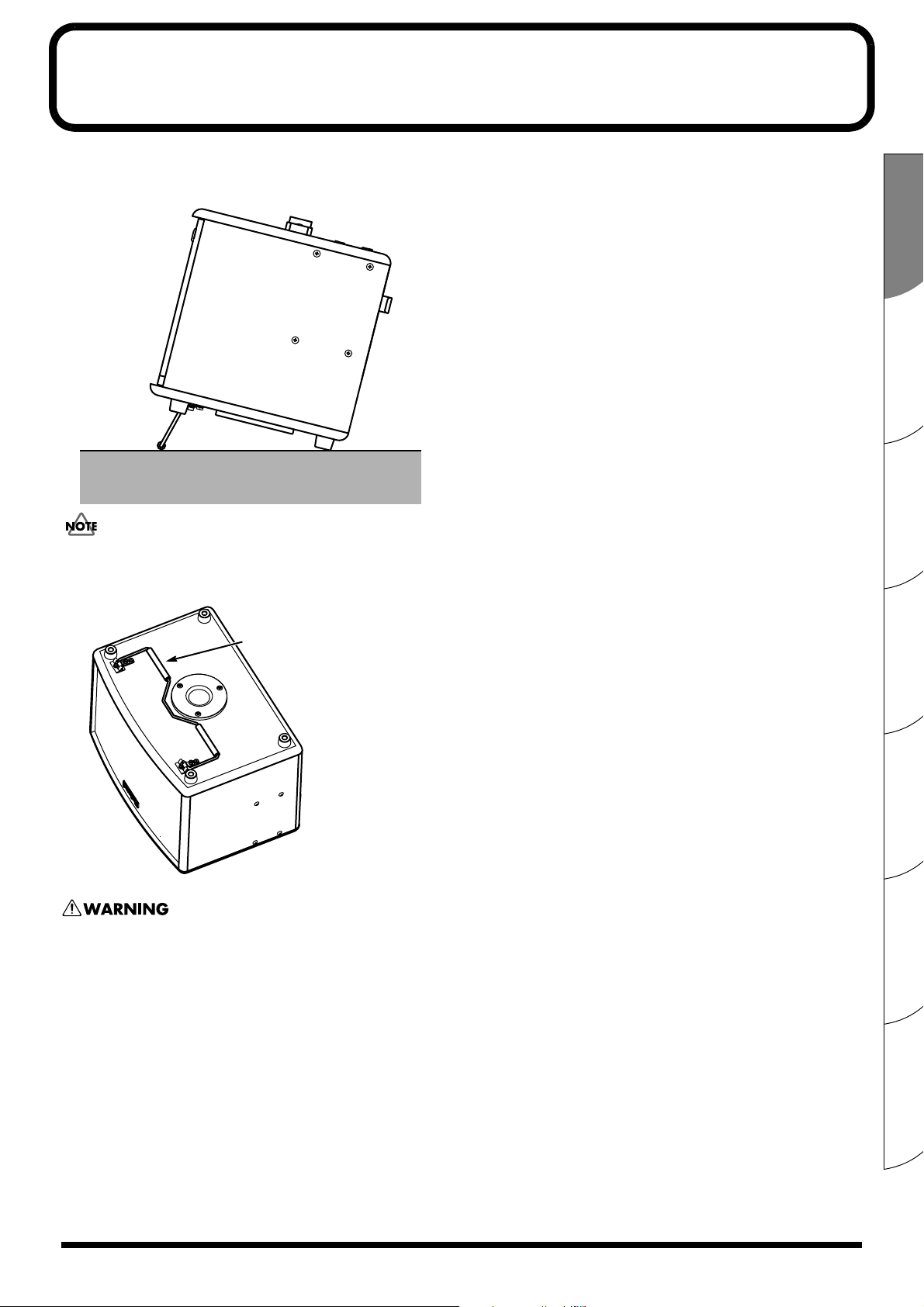
How to Use the Folding Stand
When using the AC-90 on floors, or in other low-lying positions, then setting up and using the folding stand can make it easier to
hear the sound from the speakers.
fig.100
• When using the folding stand, always be sure to place it so the AC-90 remains level.
• When not using the folding stand, fold it up.
Folding stand
• Never lift up and carry the AC-90 by holding the folding stand.
• Never place any objects on top of the AC-90 when using the folding stand. Also, never sit or lean on the folding stand.
• When folding the folding stand, be careful not to pinch your fingers.
Español Italiano Français Deutsch EnglishPortuguêsNederlands
15
Page 16
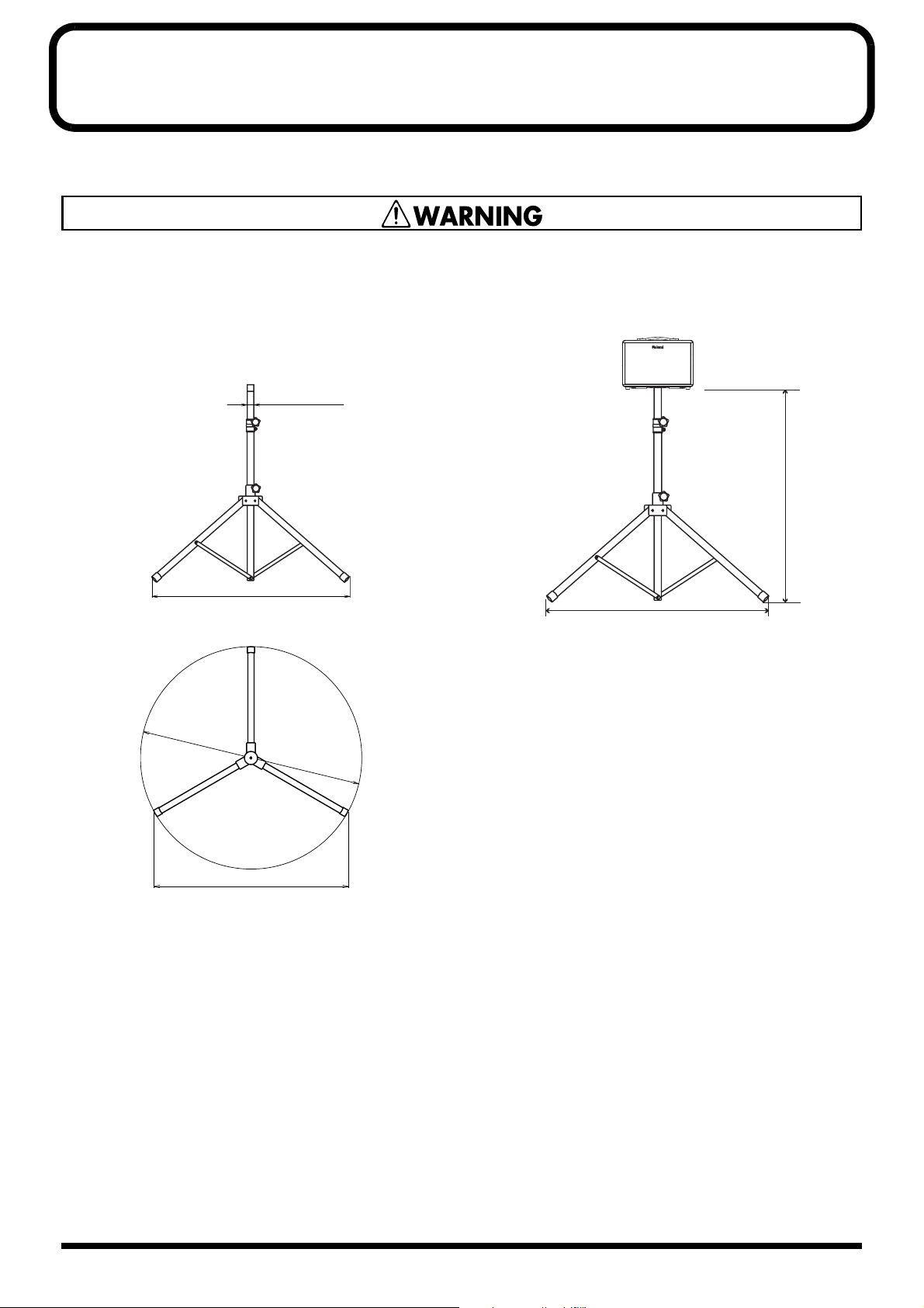
Using a Speaker Stand
By using a speaker stand, you can mount the AC-90 at the optimal height for use as a monitor speaker or simple PA device.
● The AC-90 is designed to be used only with speaker
stands whose dimensions meet the specifications
described below.
Do not use it with a speaker stand that does not meet the
following specifications.
fig.120
Diameter: 3.8 cm
(
)
1-1/2”
fig.130
Leg spread: 120 cm or more
Diameter:
136 cm or more
(
53-9/16”
(
)
47-1/4”
)
● Before use, adjust the speaker stand to a height of 140 cm
(55-1/8”) or less and a leg spread of 120 cm (47-1/4”) or
more, as shown in the figure below.
fig.110\
140 cm or less
(55-1/8”)
120 cm or more
(
)
47-1/4”
● Using a speaker stand that does not meet the
specifications at left or that is adjusted to a height over
140 cm (55-1/8”), or a leg spread of less than 120 cm (471/4”) may result in damage to equipment or injury due to
the stand tipping over.
Leg spread: 120 cm or more
(
47-1/4”
)
● When using the AC-90 with a speaker stand, the speaker
stand must be carefully placed so it is level and sure to
remain stable.
● Cables connected to the AC-90 should be given enough
slack to prevent accidents that might result from someone
tripping over them.
● To prevent accidents due to falls, do not place any object
on the AC-90 when it’s mounted on a speaker stand.
● Always have at least one other person assist you when
mounting the AC-90 on a speaker stand, or when
adjusting the height of the stand while the AC-90 remains
mounted on it.
16
Page 17

Hauptmerkmale
Der AC-90 ist ein speziell zur Verwendung mit akustischen Instrumenten entwickelter Hochleistungs-Monitorverstärker.
Er ist in der Lage, den gesamten harmonischen Klangreichtum eines akustischen Instruments originalgetreu auszudrücken.
Kompakter HochleistungsStereoverstärker
• Das fein abgestimmte Gehäusedesign ist dazu ausgelegt, den
Klang akustischer Instrumente zu bereichern. In diesem
Gehäuse befinden sich zwei 20-cm-Woofer, zwei Tweeter
und ein 2 x 45 W-Stereoverstärker – die alle speziell für den
AC-90 neu entwickelt werden. Als Resultat ist das Gerät in
der Lage, in einem breiten Frequenzspektrum einen
natürlicheren Akustikinstrumentenklang zu erzeugen.
• Durch den so leicht wie möglich konstruierten
Aktivverstärker und den Einsatz neuer Materialien
für die Woofer wurde eine Verringerung des
Gesamtgewichts des Geräts erreicht.
Zwei unabhängige Kanäle: GUITAR
und MIC/LINE
• Zu jedem Kanal gehört ein 3-Band-Equalizer.
• Der GUITAR-Kanal kann sowohl für piezoelektrische als
auch magnetische Tonabnehmer verwendet werden.
• Der MIC/LINE-Kanal bietet eine Phantomspeisung,
die durch eine äußerst zuverlässige, dezidierte
Phantomspeisungsschaltung mit einer
Ausgangsspannung von 48 V erzeugt wird.
• Mit Hilfe des MIC/LINE-Kanals für LINE-Eingänge
können Sie Gitarren mit magnetischen Tonabnehmern
anschließen. Sie können auch einen piezoelektrischen
(GUITAR-Kanal) und einen magnetischen Tonabnehmer
(MIC/LINE-Kanal) gleichzeitig verwenden und die
Klänge zusammenmischen.
Hochwertige Digitaleffekte
• Es stehen drei Arten von Stereo-Choruseffekten zur
Verfügung. Dies sind der räumlich synthetisierte
Chorus-Effekt „SPACE“, der Chorus-Effekt „RICH“ (der
in Frequenzbänder unterteilt ist) und der Chorus-Effekt
„WIDE“ (der ebenfalls in Frequenzbänder unterteilt ist,
dabei aber eine noch größere Tragweite bietet).
• Speziell für akustische Instrumente entwickelter StereoHalleffekt (Reverb). Dieser ermöglicht Ihnen, dem Klang
Raumwirkung und natürliche Substanz zu verleihen.
• Echoeffekte (Delay), die Klänge mit einer weichen und
speziell auf akustische Instrumente abgestimmten
Tonqualität erzeugen können.
• Ein optionaler Fußschalter zum Ein- und Ausschalten
der Effekte verwendet werden.
Anti-Feedback-Funktion unterdrückt
Rückkopplungen
• Die Anti-Feedback-Funktion bietet zwei Erkennungsarten für
den Rückkopplungspunkt. Sie können die „Manual Settings“
(manuellen Einstellungen) verwenden, oder Sie können die
„Auto Settings“ (automatischen Einstellungen) nutzen, mit
denen der Rückkopplungspunkt automatisch erkannt wird.
• Sie können einen optionalen Fußschalter anschließen
und diese Funktion mit dem Fuß steuern.
Stummschaltungsfunktion (Mute)
• Der Mute-Schalter macht es Ihnen leicht, den Klang der
eigenen Lautsprecher des AC-90 sowie den Klang über
LINE OUT stumm zu schalten. Mit Hilfe der MuteFunktion können Sie die Gitarre geräuschlos anschließen
und trennen. Außerdem können Sie, wenn Sie an TUNER
OUT ein Stimmgerät anschließen, Ihr Instrument mit der
Mute-Funktion stimmen, ohne dass Ton ausgegeben wird.
• Sie können einen optionalen Fußschalter anschließen
und diese Funktion mit dem Fuß ein- und ausschalten.
Externe Eingangsbuchsen (AUX IN)
• Der Verstärker besitzt externe Eingangsbuchsen, an die
Sie Stereosignale von einem CD-Spieler, einer
Begleitungsmaschine oder einem anderen Gerät
anschließen können.
• Die Eingänge verfügen sowohl über Cinch-Buchsen als
auch 6,3-mm-Klinkenbuchsen, sodass praktisch jedes
beliebige Gerät angeschlossen werden kann.
Mehrere Ausgangsanschlüsse
•Über den Ausgang DI OUT werden die von
angeschlossenen Instrumenten und Mikrofonen
eingehenden Signale direkt ausgegeben. Zudem können
Sie ein Stimmgerät anschließen. Die Ausgabe über
symmetrische Klinkenbuchsen wird unterstützt.
• Zu den Line-Ausgängen gehören neben den XLRAnschlüssen für den Stereo-Ausgang auch 6,3-mm-MonoAusgangsbuchsen. Sie können einen einzigen AC-90 für
alle Zwecke einsetzen.
• Zusätzlich besitzt der Verstärker einen SubwooferAusgang. Wenn Sie einen Aktiv-Subwoofer anschließen,
können Sie mit einem noch kraftvolleren, stärkeren
unteren Frequenzbereich spielen.
• Der Verstärker ist darüber hinaus mit einer
Kopfhörerbuchse ausgestattet, die Sie zum Spielen
während der Nacht oder für Soundchecks nutzen können.
Praktische Aufstellmöglichkeiten
• Der Verstärker besitzt einen ausklappbaren Bügel, durch
den der Winkel des Verstärkers bei Verwendung als
Monitor verstellt werden kann.
• Mit dem Lautsprecherstativ-Adapter können Sie den
AC-90 auf einem Lautsprecherstativ aufstellen. Dies
erleichtert Ihnen die Verwendung des AC-90 bei
Auftritten im Stehen und ermöglicht Ihnen, den
Verstärker als einfache PA-Anlage zu verwenden.
• Im Lieferumfang ist auch ein Tragekoffer enthalten,
damit das Gerät besser transportiert werden kann.
English
Español Italiano Français DeutschPortuguêsNederlands
17
Page 18
Bezeichnungen und Funktionen der Bedienelemente
Bedienfeld
Abb. 010
12 3
45
1. INPUT (Eingänge)
(GUITAR CHANNEL)
Schließen Sie hier Gitarren an.
(MIC/LINE CHANNEL)
Schließen Sie hier Mikrofone und Geräte mit Line-Pegel an.
Sie können auch Gitarren anschließen, deren Tonabnehmer
Vorverstärker besitzen.
Es werden symmetrische Eingänge verwendet, sodass Sie
6,3-mm-Klinken- und XLR-Stecker anschließen können.
Abb. 030
10 11 16 17
9678
12 13 14 15 18
3. Taste SHAPE (Form)
Wenn Sie diese Taste einschalten (ON), wird der mittlere
Frequenzbereich so modifiziert, dass ein strahlender Klang
erzeugt wird, der sich zum Schlagen von Akkorden eignet.
Dies betont die Saitenanschlagsklänge, so dass Sie die Saiten
mit schärferen Ausdruck anschlagen können.
4. Schalter PHANTOM
Schaltet die Phantomspeisung ein und aus.
Schalten Sie diesen Schalter ein (ON), wenn Sie Mikrofone
anschließen, die eine Phantomspeisung benötigen
(Kondensatormikrofon usw.).
Schalten Sie ihn aus (OFF), wenn Sie Mikrofone, die keine
Phantomspeisung benötigen, oder andere Geräte anschließen.
XLRTRS
Sie können die beiden Kanäle in Kombination verwenden.
Siehe hierzu „Beispiel für die kombinierte Verwendung
zweier Kanäle“ (S. 24).
983
* Je nach dem Aufstellort von Mikrofonen im Verhältnis zu den
Lautsprechern könnten Rückkopplungen erzeugt werden. Dies
können Sie beheben, indem Sie:
• Die Richtung des Mikrofons/der Mikrofone ändern.
• Das Mikrofon/die Mikrofone in größerer Entfernung von
den Lautsprechern aufstellen.
• Die Lautstärkepegel herunterregeln.
2. Taste PICKUP (Tonabnehmer)
Hiermit schalten Sie die Eingangsschaltungen entweder für
piezoelektrische oder für magnetische Tonabnehmer um, je
nachdem, welche Tonabnehmerart die angeschlossene Gitarre
besitzt. Drücken Sie die Taste für magnetische Tonabnehmer.
* Bringen Sie die Taste in die Stellung „MAGNETIC“, wenn Ihre
Gitarre einen Aktivtonabnehmer mit Vorverstärker besitzt.
18
• Gehen Sie in folgender Reihenfolge vor, wenn Sie Mikrofone
anschließen, die eine Phantomspeisung benötigen:
1. Schalten Sie den PHANTOM-Schalter aus.
2. Schließen Sie das Mikrofon an.
3. Schalten Sie den PHANTOM-Schalter ein.
• Wenn Mikrofone, die keine Phantomspeisung benötigen,
oder andere Geräte mit eingeschalteter
Phantomspeisung betrieben werden, kann dies zu
Fehlfunktionen der Mikrofone bzw.Geräte führen.
Achten Sie immer darauf, den Schalter auszuschalten,
bevor Sie den Anschluss vornehmen.
* Um die Schaltungen zu schützen, werden alle Ausgänge nach
dem Ein- oder Ausschalten des PHANTOM-Schalters
vorübergehend stumm geschaltet.
* Die Phantomspeisung erfolgt nur über die XLR-Anschlüsse
für den Eingang des MIC/LINE-Kanals.
* Wenn Anschlüsse bei eingeschalteter Phantomspeisung
vorgenommen oder getrennt werden, kann es zu
Störgeräuschen kommen.
Page 19
Bezeichnungen und Funktionen der Bedienelemente
Phantomspeisung
Da sie verglichen mit dynamischen Mikrofonen ein breiteres
Frequenzspektrum und eine bessere Klangqualität besitzen,
werden für akustische Gitarren häufig Kondensatormikrofone
verwendet. Für ihren Betrieb wird jedoch eine Stromquelle
benötigt. Einige Kondensatormikrofone arbeiten zwar mit
Batterien, die sich im Mikrofongehäuse befinden, doch in vielen
Fällen wird die als „Phantomspeisung“ bezeichnete Art der
Stromversorgung benötigt. Diese Stromversorgung nutzt das
vorhandene Mikrofonkabel, um das Mikrofon mit Strom zu
versorgen.
Die Phantomspeisung des AC-90 besitzt eine konstante
Spannung von 48 V und entspricht somit den in
Aufnahmestudios erforderlichen professionellen
Spezifikationen.
5. Taste SELECT (Auswahl)
Schaltet den Eingangspegel passend für das angeschlossene
Gerät um (Mikrofon oder Line-Pegel-Gerät).
Wenn mit der SELECT-Taste die Einstellung LINE
ausgewählt wird, können Sie Gitarren mit magnetischen
Tonabnehmern anschließen.
* Beachten Sie, dass die Lautstärke zunimmt, wenn der Schalter
auf „MIC“ gestellt wird, während ein Gerät mit Line-PegelAusgang angeschlossen ist.
9. Regler TREBLE (Höhen)
Regeln den Pegel des hohen Frequenzbereichs.
Die Klangfarbe akustischer Instrumente kann von einem
Instrument zum nächsten enorm variieren. Die gewünschte
Art des Klangs variiert ebenfalls je nachdem, wie ein
Instrument in einem bestimmten Ensemble eingesetzt wird.
Verwenden Sie aktiv die Regler BASS, MIDDLE und
TREBLE, um die Klangfarbe so einzustellen, dass sie zu dem
von Ihnen verwendeten Instrument und den Umständen
passt, in denen es verwendet wird.
(Beispiel)
• Wenn Sie den AC-90 mit Lautsprecherstativ aufgestellt
verwenden, möchten Sie vielleicht den BASS-Regler
hochdrehen, damit der Tiefenbereich besser
wahrgenommen wird.
• Wenn der Klang zu scharf wirkt, beispielsweise
unmittelbar nach dem Wechseln der Saiten, möchten Sie
vielleicht den TREBLE-Regler herunterdrehen, um die
hohen Frequenzen zu dämpfen.
10. Tasten CHORUS
Schalten den Chorus-Effekt ein und aus.
Wenn er eingeschaltet ist, leuchtet die Anzeigelampe.
English
6. Regler VOLUME (Lautstärke)
(GUITAR CHANNEL)
Reguliert die Lautstärke des GUITAR-Kanals.
* Um dem geringeren Ausgangspegel von piezoelektrischen
Tonabnehmern Rechnung zu tragen, ist der Lautstärkepegel,
wenn sich der VOLUME-Regler zwischen den Stellungen 7
und 10 befindet, bei auf PIEZO gestellter PICKUP-Taste
verglichen mit der MAGNETIC-Einstellung etwas höher.
(MIC/LINE CHANNEL)
Reguliert die Lautstärke des MIC/LINE-Kanals.
* Wenn Sie den AC-90 mit gemischtem GUITAR- und MIC/
LINE-Kanal verwenden, stellen Sie mit dem VOLUMERegler die Lautstärkebalance zwischen den beiden Kanälen ein.
7. Regler BASS
Regeln den Pegel des tiefen Frequenzbereichs.
8. Regler MIDDLE (Mitten)
Regeln den Pegel des mittleren Frequenzbereichs.
Sie können den Chorus-Effekt mit einem Fußschalter (dem
optionalen BOSS FS-5U) ein- und ausschalten. Das Ein- und
Ausschalten des Chorus-Effekts mit dem Fußschalter
funktioniert auf beiden Kanälen.
11. Regler CHORUS
Drehen Sie diesen Regler, um unter den drei Typen des
Chorus-Effekts zu wählen (SPACE, RICH und WIDE).
Durch Verstellen des Reglers können Sie einstellen, mit
welcher Intensität der Effekt angewendet wird.
* Diese Funktion ist aktiviert, wenn sich die CHORUS-Taste in
der Stellung ON befindet.
* Die Stellungsmarkierungen der Effektarten SPACE und
RICH sind Näherungsangaben. Hören Sie sich den Klang an,
während Sie die Einstellungen vornehmen, um die
Effektwirkung zu überprüfen.
SPACE (Raum)
Dies ist ein räumlich synthetisierter Chorus-Effekt. Beim
räumlich synthetisierten Chorus-Effekt, einer nur in Stereo
verfügbaren Methode, wird der Chorus-Effekt erzeugt, indem
der Klang vom rechten Lautsprecher (von dem der Effektklang
ausgegeben wird) und der Klang vom linken Lautsprecher (der
den direkten Klang ausgibt) im tatsächlichen Raum gemischt
werden. Dadurch entsteht eine größere seitliche Streuung, als
wenn die Klänge elektronisch gemischt werden, was einen
natürlicheren Eindruck von Breite hervorruft.
Español Italiano Français DeutschPortuguêsNederlands
19
Page 20
Bezeichnungen und Funktionen der Bedienelemente
RICH (Voll)
Dies ist ein in drei Frequenzbereiche unterteilter StereoChorus-Effekt.
Hier ist der Effekt in drei Bänder getrennt, tiefe, mittlere
und hohe Frequenzen, und die Anwendung der am besten
geeigneten Intensität des Chorus-Effekts in jedem Bereich
erzeugt einen Eindruck von Klangfülle und -breite, der
perfekt zur akustischen Gitarre passt.
Der untere Frequenzbereich befindet sich stabil in der Mitte, und
der Klang breitet sich mehr und mehr aus, während der Klang
vom mittleren Bereich in die höheren Frequenzen hinaufsteigt.
WIDE (Breit)
Dieser Chorus-Effekt stützt sich ebenfalls auf die
Unterteilung des Klangs in getrennte Frequenzbänder, bietet
aber ein noch größeres Ausdehnungsvermögen als RICH.
Das Klangbild breitet sich über die Lautsprecher des AC-90
hinaus aus und erzeugt einen Effekt, der den Zuhörer in den
Klang einzuhüllen scheint.
12. Regler REVERB/DELAY (Hall/Echo)
Durch Verstellen dieses Reglers können Sie zwischen dem
Hall- und dem Echo-Effekt umschalten.
Durch Verstellen des Reglers können Sie einstellen, mit
welcher Intensität der Effekt angewendet wird.
* Drehen Sie den Regler auf „OFF“ (Aus), wenn Sie den Hall-
oder Echo-Effekt nicht verwenden möchten.
* Die Stellungsmarkierungen der Typen REVERB und DELAY
sind Näherungsangaben. Hören Sie sich den Klang an,
während Sie die Einstellungen vornehmen, um die
Effektwirkung zu überprüfen.
REVERB (Hall)
Dieser speziell für akustische Instrumente entwickelte
Stereo-Halleffekt erzeugt den Eindruck von Räumlichkeit
und natürlicher Klangqualität.
Drehen Sie den Regler, um die Lautstärke des Hall-Effekts
einzustellen.
DELAY (Echo)
Dieser speziell für akustische Instrumente entwickelte EchoEffekt fügt dem ursprünglichen Klang weiche Reflexionen hinzu.
Drehen Sie den Regler, um die Verzögerungszeit zu ändern.
* Sie können den Hall- und den Echo-Effekt mit einem Fußschalter
(dem optionalen BOSS FS-5U) ein- und ausschalten.
13. Regler FEQUENCY (Frequenz)
Wählt die Frequenz aus, bei der die Anti-Feedback-Funktion
arbeitet.
Außerdem bestimmt die Stellung des Reglers, ob die
automatischen oder die manuellen Einstellungen ausgewählt sind.
Abb. 031
MANUELL
* Drehen Sie den Regler auf „OFF“ (Aus), wenn Sie den Anti-
Feedback-Effekt nicht verwenden möchten.
14. Taste START
Wird für Auto-Einstellungen verwendet (S. 21). Beim
Drücken der Taste wird die automatische Erkennung
pfeifender Rückkopplungsfrequenzen durchgeführt.
Die Anzeigeleuchten zeigen den Betriebszustand der
automatischen Erkennungsfunktion an.
Bereitschaftszustand: Langsames Blinken
Während der Erkennung: Schnelles Blinkten
Nach der Erkennung: Dauerhaftes Leuchten
* Wenn die START-Taste mindestens eine Sekunde lang
gedrückt wird, kehrt das Gerät in den Bereitschaftszustand für
die automatische Erkennung zurück.
Verwendung der ANTI-FEEDBACK-Funktion
Abb. 32
Mit der Anti-Feedback-Funktion werden Rückkopplungen
eingedämmt, die zwischen Gitarre bzw. Mikrofon und dem
Verstärker entstehen.
Die Rückkopplung wird unterdrückt, indem die Frequenz,
bei der sie auftritt, abgeschwächt wird.
* Diese Funktion ist nicht für die Unterdrückung von Hochfrequenz-
Rückkopplungen ausgelegt, die beim Verwenden von Mikrofonen
auftreten können.
Die Anti-Feedback-Funktion kann auf zwei verschiedene Arten
verwendet werden; Sie können entweder die automatischen
Einstellungen oder die manuellen Einstellungen nutzen.
* Verwenden Sie eine dieser Einstellungsarten, wenn pfeifende
Rückkopplungen auftreten.
Rückkopplung
Dies ist ein Phänomen, bei dem von den Lautsprechern ausgegebene Signale wieder vom Mikrofon oder Tonabnehmer aufgenommen werden und der Klang weiter verstärkt und von den
Lautsprechern ausgegeben wird, was zu einem unangenehmen
oszillierenden Klang führt.
* Wenn die Anti-Feedback-Funktion allein die Rückkopplung nicht
eindämmt, passen Sie Ihre Einstellungen an, in dem Sie beispielsweise
die Lautstärke verringern oder die tiefen Frequenzen reduzieren.
* Um Rückkopplungen bei einem Auftritt zu verhindern, empfehlen wir
Ihnen, die Anti-Feedback-Einstellung vor dem Auftritt vorzunehmen.
20
Page 21
Bezeichnungen und Funktionen der Bedienelemente
Automatisches Einstellen des Rückkopplungspunkts
Dadurch wird die Frequenz, bei eine Rückkopplung auftritt,
automatisch erkannt und die Rückkopplung unterdrückt.
* Verwenden Sie diese Funktion beim Auftreten von Rückkopplungen.
1. Erzeugen Sie eine pfeifende Rückkopplung.
2. Drehen Sie den FREQUENCY-Regler auf die Stellung
„AUTO“.
Abb. 033
Die ANTI-FEEDBACK-Anzeigeleuchte blinkt langsam, und die
automatische Erkennung geht in den Bereitschaftszustand.
3. Drücken Sie die START-Taste.
Die automatische Erkennung des Rückkopplungspunkts
beginnt. Die Leuchte blinkt rasch, während die Erkennung
fortschreitet, und wenn der Rückkopplungspunkt gefunden ist,
leuchtet sie stetig. Wenn kein Rückkopplungspunkt erkannt
wird, blinkt die Leuchte langsam, und die automatische
Erkennungsfunktion kehrt in den Bereitschaftszustand zurück.
4. Drücken Sie noch einmal die START-Taste, um die
automatische Erkennung erneut durchzuführen.
Manuelles Einstellen des Rückkopplungspunkts
1. Erzeugen Sie eine pfeifende Rückkopplung.
2.
Drehen Sie den Regler, so dass Sie sich durch den Bereich
von L (tief) bis H (hoch) bewegen (die ANTI-FEEDBACKAnzeigeleuchte leuchtet auf), um nach der Frequenz zu
suchen, bei der die Rückkopplung unterdrückt werden soll.
Abb. 34
Durch Drehen des Reglers im Uhrzeigersinn werden fortschreitend
mehr Höhenrückkopplungen unterdrückt, durch Drehen gegen
den Uhrzeigersinn fortschreitend mehr Bassrückkopplungen.
Sie können einen Fußschalter (den optionalen BOSS FS-5U)
benutzen, um die automatische Erkennung der
Rückkopplungsfrequenz durchzuführen oder die AntiFeedback-Funktion ein- und auszuschalten.
15. Taste MUTE (Stummschaltung)
Schaltet die Mute-Funktion ein und aus.
Wenn Sie die Taste drücken, blinkt die MUTE-
Anzeigeleuchte, die Stummschaltung wird aktiviert, und der
Lautsprecherausgang sowie die Klangausgabe über SUB
WOOFER OUT und LINE OUT werden stumm geschaltet.
Bei aktivierter Mute-Funktion brauchen Sie den VOLUME-Regler
oder MASTER-Regler nicht herunterzudrehen, um Störgeräusche
beim Ein- oder Ausstecken Ihrer Gitarre stumm zu schalten.
* Die Klangausgabe über die Buchsen DI OUT/TUNER OUT
und PHONES wird nicht stumm geschaltet.
Wenn Sie ein Stimmgerät (optional) an die Buchse DI OUT/
TUNER OUT anschließen und dann die MUTE-Taste
drücken, können Sie Ihr Instrument stimmen, ohne dass der
Klang von den Lautsprechern ausgegeben wird.
Sie können die Stummschaltung mit einem Fußschalter (dem
optionalen BOSS FS-5U) aktivieren und aufheben (S. 23).
16. Regler MASTER (Gesamtlautstärke)
Reguliert den Gesamtlautstärkepegel.
* LINE OUT kann nicht eingestellt werden.
17. Buchse PHONES (Kopfhörer)
Hier kann ein Kopfhörer angeschlossen werden. Über die
Lautsprechern und den Ausgang SUB WOOFER OUT wird
kein Klang ausgegeben, wenn ein Kopfhörer angeschlossen ist.
18. Schalter POWER (Netzschalter)
Schaltet den AC-90 ein und aus.
Die POWER-Anzeige leuchtet, wenn das Gerät eingeschaltet ist.
945
* Wenn Sie die Stromversorgung vollständig unterbrechen müssen,
schalten Sie erst den POWER-Schalter aus und ziehen Sie dann das
Netzkabel aus der Steckdose. Siehe
942
* Aufgrund einer Schaltungsschutzfunktion dauert es nach dem
Einschalten einen Moment, bis dieses Gerät für den normalen
Betrieb bereit ist.
943
* Achten Sie immer darauf, die Lautstärke herunterzuregeln, bevor
Sie das Gerät einschalten. Auch bei vollständig heruntergeregelter
Lautstärke hören Sie beim Einschalten möglicherweise einen
Klang, aber das ist normal und stellt keine Fehlfunktion dar.
Power Supply
(S. 5).
English
Español Italiano Français DeutschPortuguêsNederlands
Sie können die Anti-Feedback-Funktion auch dann verwenden,
wenn Rückkopplungen kein Problem darstellen. Beispielsweise
können Sie sie verwenden, um unerwünschte Resonanzen im
unteren bis mittleren Frequenzbereich zu unterdrücken sowie
um andere Probleme mit der Klangqualität zu beheben.
21
Page 22

Bezeichnungen und Funktionen der Bedienelemente
Rückseite
Abb. 040
5431 2
*
PCS-31
Weiß Rot
Schlagzeugmaschine
Aktiv-Subwoofer
Mischpult
926a
Wenn Verbindungskabel mit Widerständen verwendet werden, kann es sein, dass der Lautstärkepegel der an die Eingänge angeschlossenen Geräte niedrig ist.
*
Sollte dies eintreten, verwenden Sie Verbindungskabel, die keine Widerstände enthalten.
Aufnahmegerät
1. Buchsen LINE OUT
Hier können Sie ein Mischpult, ein Aufnahmegerät oder ein
anderes Gerät anschließen. Der Ausgangspegel beträgt +4 dBu.
Hier befinden sich XLR-Anschlüsse (L/R: Stereoausgang)
und eine 6,3-mm-Klinkenbuchse (Monoausgang).
Abb. 090
CD-Spieler
Mischpult
Stimmgerät
2. Buchse SUB WOOFER OUT
Hier können Sie einen Aktiv-Subwoofer anschließen, um
Klänge mit einem noch kraftvolleren, stärkeren unteren
Frequenzbereich wiederzugeben.
Die Lautstärke wird mit dem MASTER-Regler eingestellt.
Stummschaltung
ein/aus
Weiß Rot
Chorus
ein/aus
Anti-Feedback-
Funktion
PCS-31
Hall/Echo
ein/aus
3. Buchsen AUX IN
Hier können Sie einen CD-Player, eine Schlagzeugmaschine oder ein
anderes Gerät anschließen und deren Klänge in Stereo wiedergeben.
Es stehen sowohl Cinch-Buchsen als auch 6,3-mm-Klinkenbuchsen
* Die Lautstärke für LINE OUT können Sie nicht mit dem
MASTER-Regler einstellen.
* Die Chorus-Effekte sind so konzipiert, dass sie die größte
Wirkung zeigen, wenn Sie die eingebauten Lautsprecher des
Geräts verwenden. Die Wirkung kann abweichen, wenn LINE
OUT anstelle der eingebauten Lautsprecher verwendet wird.
zur Verfügung. Wird ein Gerät nur an die linke 6,3-mmKlinkenbuchse angeschlossen, erfolgt die Wiedergabe in Mono.
Das Eingangssignal über AUX IN wird von den
Lautsprechern sowie über PHONES und SUB WOOFER
OUT ausgegeben, nicht aber über LINE OUT. Die Lautstärke
wird mit dem MASTER-Regler eingestellt, und die
22
Page 23
Bezeichnungen und Funktionen der Bedienelemente
Stummschaltung für diese Klänge wird mit der MUTE-Taste
aktiviert/aufgehoben.
Wenn Geräte sowohl an die Cinch-Buchsen als auch an die
6,3-mm-Klinkenbuchsen angeschlossen sind, werden die
beiden Eingangssignale gemischt.
4. Buchse DI OUT/TUNER OUT
Über diese Buchse wird der Direktklang des Geräts oder
Instruments ausgegeben, das an den GUITAR- oder MIC/
LINE-Kanal angeschlossen ist. Dies ist eine 6,3-mmKlinkenbuchse mit symmetrischem Ausgang.
An diese Buchse können Sie auch ein Stimmgerät anschließen.
Abb. 070
* Wenn kein symmetrischer Ausgang benötigt wird, nehmen Sie
den Anschluss über diese Buchse mit einem 6,3-mmKlinkenstecker (Mono) vor.
Wenn kein symmetrischer Ausgang benötigt wird, können
Sie das Spezialverbindungskabel (das optionale PCS-31)
verwenden, um die Buchsen DI OUT und TUNER OUT
gleichzeitig zu nutzen.
Abb. 080
PCS-31
Weiß Rot
Stimmgerät
(MUTE, ANTI-FEEDBACK)
Durch Anschließen eines Fußschalterpedals (optionales
BOSS FS-5L, FS-5U oder FS-6) über ein Verbindungskabel
(das optionale PCS-31) wird es möglich, einen rastenden
Fußschalter (den FS-5L oder FS-6) zum Aktivieren und
Aufheben der Stummschaltung zu verwenden oder einen
Tastfußschalter (den FS-5U oder FS-6) zum Steuern der AntiFeedback-Funktion zu verwenden.
* Informationen zu den Einstellungen für den FS-6 finden Sie
in der Bedienungsanleitung für den FS-6.
Abb. 050
Wenn eine 6,3-mm-Klinkenbuchse (Mono) verwendet wird,
um nur einen Fußschalter anzuschließen, ist nur die MuteEin/Aus-Funktion aktiviert. In solchen Fällen sollten Sie ein
rastendes Fußschalterpedal benutzen (beispielsweise das
BOSS FS-5L).
* Die MUTE-Taste muss ausgeschaltet sein, wenn für die
Stummschaltung ein Fußschalter angeschlossen ist.
Sie können die Stummschaltung nicht durch Betätigen des
Fußschalters aufheben, wenn die MUTE-Taste eingeschaltet
ist (wenn die MUTE-Anzeige leuchtet).
* Wenn ein FS-5U (Taster) zum Aktivieren und Aufheben der
Stummschaltung verwendet wird, wird die Stummschaltung
nur bei gedrückt gehaltenem Schalter aktiviert.
Für die Anti-Feedback-Funktion fungiert ein Fußschalter
folgendermaßen:
• Wenn der FREQUENCY-Regler auf den Bereich
zwischen L bis H eingestellt ist, schaltet der Schalter die
Anti-Feedback-Funktion ein und aus.
• Wenn der FREQUENCY-Schalter auf AUTO steht,
fungiert der Schalter als START-Schalter für die
automatische Erkennung. Wenn der Fußschalter
mindestens eine Sekunde lang gedrückt wird, kehrt das
Gerät in den Bereitschaftszustand für die automatische
Erkennungsfunktion zurück.
English
Español Italiano Français DeutschPortuguêsNederlands
Aufnahmegerät
Von der KALTEN Seite (der roten Seite des PCS-31) wird ein Signal
mit umgekehrter Phase ausgegeben. Schließen Sie das
Aufnahmegerät an die HEISSE Seite an (die weiße Seite des PCS-31).
5. Buchsen FOOT SW (Fußschalter)
An den AC-90 können die Fußschalterpedale BOSS FS-5L
(rastender Schalter), BOSS FS-5U (Taster) und BOSS FS-6
angeschlossen werden.
* Stellen Sie den Polaritätsschalter wie nachstehend gezeigt ein.
Abb. 071
(CHORUS, DELAY/REVERB)
Wenn Sie ein Spezialverbindungskabel (das optionale PCS-
31) zum Anschließen von zwei Fußschaltern verwenden
(BOSS FS-5U, optional), können Sie mit einem FS-5U den
Chorus-Effekt ein- und ausschalten und mit dem anderen FS5U den Hall- bzw. Echo-Effekt ein- und ausschalten.
Abb. 060
Wenn eine 6,3-mm-Klinkenbuchse (Mono) verwendet wird,
um nur einen Fußschalter anzuschließen, ist nur die ChorusEin/Aus-Funktion aktiviert.
* Die Chorus-Ein/Aus-Funktion wirkt auf beide Kanäle.
* Sie können den Chorus-Effekt nicht durch Betätigen des Fußschalters
ein- und ausschalten, wenn die CHORUS-Taste ausgeschaltet ist.
23
Page 24

Beispiel für die kombinierte Verwendung zweier Kanäle
Wenn ein Mikrofon und ein
Tonabnehmer verwendet werden
GUITAR CHANNEL:
Piezoelektrischer oder magnetischer Tonabnehmer
MIC/LINE CHANNEL:
Kondensator- oder dynamisches Mikrofon (SELECT-Taste = MIC)
Dies ermöglicht Ihnen, den fetten Mittenbereich des Tonabnehmers
mit dem zarten hohen Frequenzbereich des Mikrofons zu mischen.
Schalten Sie den PHANTOM-Schalter ein (ON), wenn Sie ein
Kondensatormikrofon verwenden.
Bei Verwendung von zwei Gitarren
GUITAR CHANNEL:
Gitarre 1 Piezoelektrischer oder magnetischer Tonabnehmer
MIC/LINE CHANNEL:
Gitarre 2 Magnetischer Tonabnehmer (SELECT-Taste = LINE)
Sie können die Gitarren wechseln, ohne Lautstärke und
Klangfarbe neu einstellen zu müssen.
PIEZO
MAGNETIC
Kondensatormikrofon oder dynamisches Mikrofon
Gitarre 1
PIEZO
MAGNETIC
oder
oder
Bei Verwendung einer Gitarre mit zwei
Tonabnehmertypen
GUITAR CHANNEL:
Piezoelektrischer Tonabnehmer (PICKUP-Taste = PIEZO)
MIC/LINE CHANNEL:
Magnetischer Tonabnehmer (SELECT-Taste = LINE)
Sie können die Lautstärkebalance mit den VOLUME-Reglern
der einzelnen Kanäle einstellen und die Klangfarbe jedes
Tonabnehmers mit den Equalizer-Reglern (BASS/MIDDLE/
TREBLE) einstellen, um den optimalen Klang zu erreichen.
Gitarre 2
MAGNETIC
PIEZO
MAGNETIC
24
Page 25

Verwendung des ausklappbaren Bügels
Wenn der AC-90 ebenerdig oder an anderen niedrigen Positionen verwendet wird, kann der Klang von den Lautsprechern durch
Ausklappen des Bügels leichter hörbar gemacht werden.
Abb. 100
English
• Wenn Sie den Bügel benutzen, achten Sie immer darauf, ihn so zu platzieren, dass der AC-90 weiterhin einen sicheren Stand hat.
• Wenn Sie den Bügel nicht verwenden, klappen Sie ihn ein.
Klappständer
• Heben und tragen Sie den AC-90 nie am Bügel.
• Legen Sie nie Gegenstände auf den AC-90, wenn Sie den Bügel verwenden. Setzen oder lehnen Sie sich auch nie auf den Bügel.
• Achten Sie beim Einklappen des Bügels darauf, sich nicht die Finger einzuklemmen.
Español Italiano Français DeutschPortuguêsNederlands
25
Page 26

Verwenden eines Lautsprecherstativs
m
Durch Verwenden eines Lautsprecherstativs können Sie den AC-90 auf optimaler Höhe anbringen, um ihn als
Monitorlautsprecher oder einfache PA-Anlage zu nutzen.
● Der AC-90 ist nur zur Verwendung mit
Lautsprecherstativen konzipiert, deren Abmessungen
den nachstehend beschriebenen Spezifikationen
entsprechen.
Verwenden Sie ihn nicht mit einem Lautsprecherstativ,
das den folgenden Spezifikationen nicht entspricht.
Abb. 120
Durchmesser: 3.8 c
(
)
1 1/2”
Beinspanne: min 120 cm
(
)
47 1/4”
Abb. 130
Durchmesser:
min 136 cm
(
53 9/16”
)
● Stellen Sie das Lautsprecherstativ, bevor Sie es
1
verwenden, auf eine Höhe von maximal 140 cm (55
/8
Zoll) und eine Beinspanne von mindestens 120 cm (47 ¼
Zoll) ein (siehe nachstehende Abbildung).
Abb. 110\
max. 140 cm
(55-1/8”)
max 120 cm
(
)
47-1/4”
● Bei Verwendung eines Lautsprecherstativs, das nicht den
links nebenstehenden Spezifikationen entspricht oder das
1
auf eine Höhe von über 140 cm (55
/8 Zoll) oder auf eine
Beinspanne von weniger als 120 cm (47 ¼ Zoll) eingestellt
ist, kann es durch ein Umkippen des Stativs zu
Beschädigungen an Geräten oder zu Verletzungen
kommen.
26
Beinspanne: min 120 cm
(
)
47 1/4”
● Wenn der AC-90 mit einem Lautsprecherstativ verwendet
wird, muss das Lautsprecherstativ sorgfältig so platziert
werden, dass es gerade und zuverlässig stabil steht.
● An den AC-90 angeschlossene Kabel sollten lose genug
verlegt sein, um Unfälle zu verhindern, die dadurch
entstehen könnten, dass jemand über sie stolpert.
● Um Unfälle durch Stürze zu verhindern, legen oder
stellen Sie keine Gegenstände auf den AC-90, wenn er auf
einem Lautsprecherstativ montiert ist.
● Lassen Sie sich immer von mindestens einer weiteren
Person helfen, wenn Sie den AC-90 auf einem
Lautsprecherstativ montieren, oder wenn Sie die Höhe
des Stativs verstellen, während der AC-90 darauf
montiert bleibt.
Page 27

Caractéristiques principales
L’amplificateur AC-90 est un appareil très performant conçu exclusivement pour des instruments acoustiques. Il est capable
d’exprimer avec fidélité toute la richesse harmonique du son d’un instrument acoustique.
Amplificateur stéréo compact hautes
performances
• Le caisson finement dessiné est conçu pour améliorer le
son des instruments acoustiques. Il contient deux hautparleurs de graves de 20 cm, deux haut-parleurs d’aigus
et un amplificateur stéréo 45 W + 45 W. Tous ces
éléments ont été élaborés expressément pour
l’amplificateur AC-90. Par conséquent, l’appareil est
capable de fournir un son instrumental acoustique plus
naturel sur une large bande de fréquences.
• Grâce à un amplificateur de puissance conçu pour être le
plus léger possible et à l’utilisation de nouveaux
matériaux pour les haut-parleurs de graves, le poids de
l’appareil a diminué.
Deux canaux indépendants : GUITAR
et MIC/LINE
• Chaque canal comporte un égaliseur 3 bandes.
• Le canal GUITAR gère à la fois les pickups piézo et
les pickups magnétiques.
• Le canal MIC/LINE fournit une alimentation fantôme
produite par un circuit fantôme dédié très fiable d’une
puissance de sortie de 48 V.
• Le canal MIC/LINE pour l’entrée LINE vous permet
de connecter des guitares avec pickups magnétiques.
Vous pouvez également utiliser simultanément un
pickup piézo (canal GUITAR) et un pickup magnétique
(canal MIC/LINE) et mixer les sons ensemble.
Effets numériques haute qualité
• Trois sortes d’effets chorus stéréo sont possibles. Chorus
« SPACE » synthétisé dans l’espace, chorus « RICH »
(divisé en bandes de fréquences) et chorus « WIDE »
(également divisé en bandes de fréquences tout en
offrant plus de souplesse).
• Réverbération stéréo développée spécialement pour les
instruments acoustiques. Elle vous permet d’ajouter de
l’amplitude et une touche de naturel au son.
• Effets « delay » (retard) pouvant produire un son doux
spécifiquement élaboré pour les instruments
acoustiques.
• Une pédale disponible en option permet également
d’activer et de désactiver les effets.
Fonction MUTE (mode Silencieux)
• Le bouton MUTE simplifie la désactivation des sons
des haut-parleurs de l’amplificateur AC-90 et de la sortie
LINE OUT. Grâce à cette fonction, vous pouvez brancher
et débrancher votre guitare sans bruit. De plus,
lorsqu’un tuner est relié à la prise TUNER OUT, la
fonction MUTE vous permet d’accorder votre instrument
en silence.
• Vous pouvez connecter une pédale en option et activer
cette fonction avec le pied.
Prises d’entrée externes (AUX IN)
• Prises d’entrée externes permettant de connecter un
lecteur CD, un appareil auxiliaire ou tout autre dispositif
stéréo.
• Prises phono RCA et jacks 1/4” permettant de connecter
tout type d’appareil.
Plusieurs connecteurs de sortie
• Sortie DI qui vous permet d’émettre directement des
signaux à partir d’instruments et de micros connectés.
Vous pouvez également y relier un tuner. Sortie
symétrique TRS prise en charge.
• Parmi les prises de sortie : prises de sortie mono 1/4”
en plus de connecteurs XLR pour sortie stéréo. Il est
possible d’utiliser un seul amplificateur AC-90 pour
toutes les applications.
• Une prise pour caisson de basse est également présente.
Un caisson de basse sous tension permet d’obtenir
un son grave plus puissant, plus incisif.
• L’amplificateur est également doté d’une prise casque,
utile pour jouer la nuit et pour contrôler le son.
Fonctions de positionnement pratiques
• Son pied pliant vous permet de changer l’angle de
l’amplificateur lors de contrôles.
• Un adaptateur permet de relier l’amplificateur AC-90
à un pied pour haut-parleur. L’amplificateur AC-90 est
ainsi plus facile à utiliser lorsque vous jouez debout et
vous pouvez l’utiliser comme simple préamplificateur.
• L’amplificateur est livré avec une housse de transport.
Deutsch English
Español Italiano FrançaisPortuguêsNederlands
Fonction anti-feedback
• L’anti-feedback offre deux possibilités de détecter le
point de feedback. Vous disposez de paramètres
manuels et de paramètres automatiques, lesquels servent
à la détection automatique du point de feedback.
• Vous pouvez connecter une pédale en option et activer
cette fonction avec le pied.
27
Page 28

Noms et fonctions des éléments
Panneau de commande
fig.010
12 3
45
1. INPUT
(GUITAR CHANNEL)
Connectez les guitares ici.
(MIC/LINE CHANNEL)
Connectez les micros et appareils de niveau ligne ici. Vous
pouvez également connecter des guitares avec pickups
équipés de préamplificateurs.
Gère l’entrée symétrique, ce qui vous permet de connecter
des prises TRS 1/4” et des connecteurs XLR.
fig.030
10 11 16 17
9678
12 13 14 15 18
3. Bouton SHAPE
Sur la position ON, ce bouton modifie les fréquences moyennes
pour créer un son clair, adapté aux raclements de cordes.
Accentue les sons « effleurés » et vous permet de gratter vos
cordes plus nerveusement.
4. Interrupteur PHANTOM
Active ou désactive l’alimentation fantôme.
Placez l’interrupteur en position ON lorsque vous connectez
des micros qui nécessitent une alimentation fantôme (micros
électrostatiques, etc.).
Placez l’interrupteur en position OFF lorsque vous connectez
des micros qui ne nécessitent pas d’alimentation fantôme ou
d’autres appareils.
XLRTRS
Vous pouvez utiliser les deux canaux ensemble.
Voir la section « Exemple d’utilisation de deux canaux
ensemble » (p. 34).
983
* Selon l’emplacement des microphones par rapport aux haut-
parleurs, un effet de feedback peut être généré. Pour y remédier :
•Changez l’orientation des microphones.
•Éloignez les microphones des haut-parleurs.
•Baissez le volume.
2. Bouton PICKUP
Ce bouton permet de commuter entre un pickup piézo et un
pickup magnétique, selon le type de pickup dont dispose la
guitare connectée. Appuyez sur le bouton pour les pickups
magnétiques.
* Choisissez « MAGNETIC » si votre guitare dispose d’un
pickup actif équipé d’un préamplificateur.
28
• Pour connecter des micros qui nécessitent une
alimentation fantôme, procédez comme suit :
1. Placez l’interrupteur PHANTOM sur OFF.
2. Connectez le micro.
3. Placez l’interrupteur PHANTOM sur ON.
• Si vous fournissez une alimentation fantôme à des
micros ou des appareils qui n’en ont pas besoin, ils
risquent de ne pas fonctionner correctement. Veillez
à toujours positionner l’interrupteur sur OFF avant de
connecter un appareil.
* Pour protéger le circuit électrique, toutes les sorties passent
momentanément en mode Silencieux lorsque l’interrupteur
PHANTOM est manipulé (ON ou OFF).
* L’alimentation fantôme est fournie uniquement aux
connecteurs XLR pour l’entrée du canal MIC/LINE.
* Du son pourra être produit si des connecteurs sont connectés
ou déconnectés pendant que l’alimentation fantôme est activée.
Page 29

Noms et fonctions des éléments
Alimentation fantôme
En raison d’une qualité sonore supérieure et d’une plage de
fréquences plus étendue par rapport aux micros dynamiques,
les micros électrostatiques sont souvent utilisés pour les
guitares acoustiques. Cependant, leur utilisation exige une
source d’alimentation. Bien que certains micros
électrostatiques fonctionnent sur une batterie placée dans
le boîtier, une alimentation fantôme est souvent nécessaire.
Ce type d’alimentation utilise le câble existant du
microphone pour fonctionner.
La sortie de l’alimentation fantôme de l’amplificateur AC-90 est
constante à 48 V. Elle est ainsi en conformité avec les normes
professionnelles requises dans les studios d’enregistrement.
5. Bouton SELECT
Permet de sélectionner le niveau d’entrée en fonction
de l’appareil connecté (MIC ou LINE).
Vous pouvez connecter des guitares avec des pickups
magnétiques lorsque le bouton SELECT est sur la position
LINE.
* Le volume augmente si le bouton est placé sur MIC lorsqu’un
appareil de niveau ligne est connecté.
6. Boutons VOLUME
9. Boutons TREBLE
Permettent de régler le niveau de la bande de hautes fréquences.
La tonalité d’un instrument acoustique peut varier
considérablement d’un instrument à un autre. Le type de
son nécessaire varie également en fonction de la façon dont
l’instrument est utilisé dans un ensemble donné. Tournez les
boutons BASS, MIDDLE et TREBLE pour parvenir au réglage
adéquat pour la tonalité de votre instrument en fonction des
conditions d’utilisation.
(Exemple)
• Si vous utilisez l’amplificateur AC-90 avec le pied pour
haut-parleur connecté, tournez le bouton BASS pour
augmenter le réglage afin de rendre plus audibles les
fréquences les plus basses.
• Si le son semble trop dur, par exemple juste après chaque
changement de corde, vous pouvez tourner le bouton
TREBLE pour diminuer le réglage et réduire ainsi les
hautes fréquences.
10. Boutons CHORUS
Permettent d’activer et de désactiver l’effet de chorus.
Lorsque cette fonction est activée, le voyant est allumé.
Deutsch English
(GUITAR CHANNEL)
Permet de régler le volume du canal GUITAR.
* Pour s’adapter à la faible sortie des pickups piézo, le niveau du
volume, lorsque le bouton VOLUME se trouve entre 7 et 10,
doit être légèrement supérieur si le bouton PICKUP est placé
sur PIEZO au lieu de MAGNETIC.
(MIC/LINE CHANNEL)
Permet de régler le volume du canal MIC/LINE.
* Si vous utilisez à la fois le canal GUITAR et le canal MIC/
LINE de l’amplificateur AC-90, réglez le volume sur une
position intermédiaire entre les deux canaux à l’aide du bouton
VOLUME.
7. Boutons BASS
Permettent de régler le niveau de la bande de basses
fréquences.
8. Boutons MIDDLE
Permettent de régler le niveau de la bande de moyennes
fréquences.
Vous pouvez utiliser une pédale (BOSS FS-5U disponible
en option) pour activer et désactiver cette fonction. Vous
pouvez activer et désactiver cette fonction avec le pied sur
les deux canaux.
11. Bouton CHORUS
Tournez ce bouton pour sélectionner l’un des trois types
de chorus (SPACE, RICH et WIDE).
Vous pouvez moduler l’effet produit en tournant le bouton.
* Pour cela, le bouton CHORUS doit être sur la position ON.
* Les indications des positions SPACE et RICH sont
approximatives. Au cours des réglages, fiez-vous à votre écoute
pour juger de l’effet produit.
SPACE
Chorus synthétisé dans l’espace. Grâce à cette méthode
disponible en stéréo uniquement, l’effet de chorus est créé
en prenant le son provenant du haut-parleur droit et le son
provenant du haut-parleur gauche, puis en les mélangeant
dans l’espace. On obtient un son plus large et plus naturel
que celui produit en mélangeant les sons électroniquement.
Español Italiano FrançaisPortuguêsNederlands
29
Page 30

Noms et fonctions des éléments
RICH
Chorus stéréo divisé en trois bandes de fréquences.
L’effet est séparé en trois bandes (basses, moyennes et hautes
fréquences). Il est appliqué selon des proportions appropriées
pour chaque bande pour aboutir à une largeur et une plénitude
sonores parfaitement adaptées à la guitare acoustique.
Les graves se trouvent au centre et le son se propage de plus
en plus au fur et à mesure que le volume s’élève, des basses
fréquences vers les fréquences plus élevées.
WIDE
Tout en reposant sur la division du son en bandes distinctes,
ce chorus est plus étendu que le chorus RICH.
Le son se propage au-delà des haut-parleurs de
l’amplificateur AC-90, produisant un effet qui semble
envelopper l’auditeur.
12. Bouton REVERB/DELAY
Ce bouton permet de commuter entre les effets de
réverbération et de retard.
Vous pouvez moduler l’effet produit en tournant le bouton.
* Positionnez ce bouton sur OFF si vous n’utilisez pas les effets
de réverbération et de retard.
* Les indications des positions REVERB et DELAY sont
approximatives. Au cours des réglages, fiez-vous à votre écoute
pour juger de l’effet produit.
fig.031
MANUEL
* Positionnez ce bouton sur OFF si vous n’utilisez pas l’anti-
feedback.
14. Bouton START
Permet de sélectionner le mode Auto (p. 31). Si vous appuyez
sur ce bouton, les feedbacks sonores seront automatiquement
détectés.
Les voyants indiquent l’état de fonctionnement de la fonction
de détection automatique.
Veille : Le voyant clignote lentement.
Détection en cours : Le voyant clignote rapidement.
Après détection : Le voyant reste allumé.
* Si vous maintenez le bouton START enfoncé pendant une seconde
ou plus, la fonction de détection automatique repasse en veille.
Utilisation de l’ANTI-FEEDBACK
fig.32
REVERB
Cette réverbération stéréo réservée aux instruments
acoustiques produit un effet d’espace et une qualité sonore
naturelle.
Tournez le bouton pour régler le volume de réverbération.
DELAY
L’effet de retard, développé spécifiquement pour les
instruments acoustiques, ajoute de la douceur au son
d’origine.
Tournez le bouton pour régler le retard.
* Vous pouvez utiliser une pédale (BOSS FS-5U disponible en
option) pour activer et désactiver ces effets.
13. Bouton FREQUENCY
Permet de sélectionner la fréquence du fonctionnement de la
fonction anti-feedback.
La position du bouton détermine si cette fonction est réglée
en mode Auto ou Manuel.
Le système anti-feedback contrôle le retour sonore qui peut
se produire entre la guitare ou le micro et l’amplificateur.
Le feedback est supprimé grâce à l’atténuation de la
fréquence à laquelle il se produit.
* Ce système ne s’adresse pas au feedback haute fréquence qui se
produit avec les microphones.
L’anti-feedback peut s’utiliser en mode Auto ou en mode
Manuel.
* Utilisez l’un ou l’autre en cas de retour sonore.
Feedback (retour sonore)
Ce phénomène se produit lorsque des signaux sont émis par
les haut-parleurs et repris par un micro ou un pickup, le son
est ensuite amplifié et de nouveau émis par les haut-parleurs.
Il en résulte un son oscillant très désagréable.
* Si l’anti-feedback seul ne permet pas de contrôler le retour
sonore, réglez les paramètres en diminuant, par exemple, le
volume ou les basses fréquences.
* Pour empêcher tout feedback au cours d’une session, il est
conseillé d’activer le système anti-feedback avant de jouer.
30
Page 31

Noms et fonctions des éléments
Détection automatique du point de feedback
La fréquence à laquelle se produit le feedback est
automatiquement détectée et le feedback est supprimé.
* À utiliser lorsqu’un feedback est susceptible de se produire.
1. Provoquez un feedback.
2. Tournez le bouton FREQUENCY jusqu'a la position
« AUTO ».
fig.033
Le voyant ANTI-FEEDBACK clignote lentement et la
détection automatique se met en veille.
3. Appuyez sur le bouton START.
La détection automatique du point de feedback commence.
Le voyant clignote rapidement lorsque la détection est en cours,
puis il reste allumé lorsque le point de feedback est détecté.
Si aucun point de feedback n’est détecté, le voyant clignote
lentement et la détection automatique repasse en veille.
4. Appuyez sur le bouton START une nouvelle fois pour
relancer la détection automatique.
Détection manuelle du point de feedback
1. Provoquez un feedback.
2. Tournez le bouton de L vers H (le voyant ANTI-
FEEDBACK s’allume) pour rechercher la fréquence
à laquelle le feedback doit être supprimé.
fig.34
15. Bouton MUTE
Active ou désactive le mode Silencieux.
Lorsque vous appuyez sur ce bouton, le voyant MUTE
clignote, le mode Silencieux est activé, la sortie haut-parleur
est coupée de même que les sorties SUB WOOFER OUT
et LINE OUT.
Lorsque le mode Silencieux (MUTE) est activé, il n’est pas
nécessaire de baisser le volume (boutons VOLUME ou
MASTER) pour couper le son lorsque vous connectez ou
déconnectez votre guitare.
* Le son provenant des prises DI OUT/TUNER OUT et
PHONES n’est pas coupé.
Si vous connectez un tuner (en option) sur la prise DI OUT/
TUNER OUT et que vous appuyez sur le bouton MUTE,
vous pouvez accorder votre instrument sans qu’aucun son ne
soit émis par les haut-parleurs.
Vous pouvez utiliser une pédale (BOSS FS-5U disponible en
option) pour activer et désactiver le mode Silencieux. (p. 33)
16. Bouton MASTER
Permet de régler le volume général.
* LINE OUT ne se règle pas.
17. Prise PHONES
Connectez un casque ici. Aucun son n’est émis par les hautparleurs ou SUB WOOFER OUT lorsqu’un casque est
connecté.
Deutsch English
Le fait de tourner le bouton dans le sens des aiguilles d’une
montre supprime progressivement le feedback des aigus, le
tourner dans le sens inverse supprime progressivement le
feedback des graves.
Vous pouvez utiliser une pédale (BOSS FS-5U disponible en
option) pour lancer la détection automatique de la fréquence du
feedback ou pour activer et désactiver le système anti-feedback.
Vous pouvez utiliser l’anti-feedback même si vous n’avez
pas problème de feedback. Par exemple, vous pouvez
l’utiliser pour supprimer une résonance gênante dans les
basses à moyennes fréquences, et pour corriger d’autres
problèmes de qualité sonore.
18. Interrupteur POWER
Permet de mettre l’amplificateur AC-90 sous tension ou hors
tension.
Le voyant d’alimentation s’allume lorsque l’amplificateur est
sous tension.
945
* Si vous devez mettre l’appareil hors tension, appuyez d’abord sur
l’interrupteur POWER, puis débranchez le cordon d’alimentation
de la prise de courant. Voir Power Supply (p. 5)
942
* En raison d’une fonction de protection du circuit, il est
nécessaire d’attendre quelques instants après la mise sous
tension de l’appareil pour pouvoir utiliser ce dernier.
943
* Assurez-vous toujours que le volume est réglé au minimum
avant de mettre l’amplificateur sous tension. Même si le
volume est réglé au minimum, il est possible que vous
entendiez un son lors de la mise sous tension de l’appareil.
C’est normal et cela n’indique pas de dysfonctionnement.
31
Español Italiano FrançaisPortuguêsNederlands
Page 32

Noms et fonctions des éléments
Panneau arrière
fig.040
5431 2
*
PCS-31
Blanc Rouge
Boîte à rythmes
Caisson de
basse alimenté
Mélangeur
926a
L’utilisation de câbles de connexion avec résistances peut diminuer le volume des appareils connectés.
*
Dans ce cas, utilisez des câbles de connexion sans résistance.
Enregistreur
1. Prises LINE OUT
Vous pouvez connecter un mélangeur, un enregistreur ou
tout autre appareil ici. Le niveau de sortie est de +4 dBu.
Des connecteurs XLR (L/R : sortie stéréo) et une prise 1/4”
(sortie mono) sont fournis ici.
fig.090
* Vous ne pouvez pas régler le volume de LINE OUT à l’aide du
bouton MASTER.
* Les effets de chorus sont conçus de manière optimale pour
l’utilisation des haut-parleurs intégrés. Leur efficacité peut
varier si la prise LINE OUT est utilisée à la place des hautparleurs intégrés.
Lecteur CD
Mélangeur
Tuner
2. Prise SUB WOOFER OUT
Vous pouvez connecter un caisson de basse sous tension
pour obtenir un son grave plus puissant, plus incisif.
Réglez le volume à l’aide du bouton MASTER.
3. Prises AUX IN
Vous pouvez connecter un lecteur CD, une boîte à rythmes
ou tout autre appareil et reproduire des sons en stéréo. Des
prises RCA et 1/4” sont fournies. Si vous êtes connecté à la
prise 1/4” de gauche, le son sortira en mono.
Bien que l’entrée AUX IN soit émise par les haut-parleurs,
PHONES et SUB WOOFER OUT, elle ne provient pas de
LINE OUT. Réglez le volume à l’aide du bouton MASTER.
L’activation et la désactivation du mode Silencieux pour ces
sons se font à l’aide du bouton MUTE.
Si des appareils sont connectés aux prises RCA et 1/4”, les
deux entrées sont mixées.
activé/
désactivé
Blanc Rouge
Chorus
activé/
désactivé
Anti-FeedbackSilencieux
PCS-31
Réverb./Retard
activé/
désactivé
32
Page 33

Noms et fonctions des éléments
4. Prise DI OUT/TUNER OUT
Le son direct de l’appareil ou de l’instrument connecté au
canal GUITAR ou MIC/LINE sort ici. Il s’agit d’une prise
TRS 1/4” avec sortie symétrique.
Vous pouvez également y relier un tuner.
fig.070
* Si vous n’avez pas besoin d’une sortie symétrique, utilisez une
prise 1/4” (mono) pour vous connecter à cette prise.
Si vous n’avez pas besoin d’une sortie symétrique, vous
pouvez utiliser le câble de connexion spécial (PCS-31 en
option) pour utiliser simultanément DI OUT et TUNER OUT.
fig.080
PCS-31
Blanc Rouge
Tuner
Enregistreur
Un signal à phase inverse est émis du côté COLD (FROID)
(côté rouge de PCS-31). Connectez l’enregistreur au côté
HOT (CHAUD) (côté blanc de PCS-31)
5. Prises FOOT SW
L’amplificateur AC-90 accepte les modèles de pédale BOSS FS-5L
(type à verrouillage), BOSS FS-5U (type fugitif) et BOSS FS-6.
* Réglez la polarité comme indiqué ci-dessous.
fig.071
(MUTE, ANTI-FEEDBACK)
Si vous connectez une pédale (modèles BOSS FS-5L, FS-5U ou
FS-6 disponibles en option) à l’aide d’un câble de connexion
(PCS-31 en option), vous pouvez choisir une pédale type
à verrouillage (FS-5L ou FS-6) pour activer/désactiver le mode
Silencieux ou une pédale type fugitif (FS-5U ou FS-6) pour
contrôler le système anti-feedback.
* Pour plus d’informations sur les réglages de la pédale FS-6,
consultez le guide d’utilisation de la pédale.
fig.050
Lorsque vous utilisez une prise 1/4” (mono) pour connecter une
seule pédale, seule la fonction d’activation et de désactivation du
mode Silencieux est activée. Il est alors préférable d’utiliser une
pédale type verrouillage (telle que BOSS FS-5L)
* Le bouton MUTE doit être en position désactivée lorsqu’une
pédale est connectée pour le mode Silencieux.
Vous ne pouvez pas désactiver le mode Silencieux en appuyant
sur la pédale lorsque le bouton MUTE est en position activée
(voyant MUTE allumé).
* Lorsque vous utilisez une pédale FS-5U (type fugitif) pour
activer/désactiver le mode Silencieux, ce mode n’est activé que
lorsque vous maintenez la pédale abaissée.
Concernant le système anti-feedback, le fonctionnement
d’une pédale est le suivant :
• Lorsque le bouton FREQUENCY est placé dans la plage L
à H, la pédale active ou désactive la fonction anti-feedback.
• Lorsque le bouton FREQUENCY est positionné sur
AUTO, la pédale fonctionne comme le bouton START
pour la détection automatique. Si vous maintenez la
pédale abaissée pendant une seconde ou plus, la fonction
de détection automatique repasse en veille.
(CHORUS, DELAY/REVERB)
À l’aide d’un câble de connexion spécial (PCS-31 en option)
permettant de relier deux pédales (BOSS FS-5U en option),
vous pouvez utiliser une pédale FS-5U pour activer ou
désactiver la fonction chorus et une autre pédale FS-5U pour
activer ou désactiver la fonction delay/reverb.
fig.060
Deutsch English
Español Italiano FrançaisPortuguêsNederlands
Lorsque vous utilisez une prise 1/4” (mono) pour connecter
une seule pédale, seule la fonction d’activation et de
désactivation de l’effet chorus est activée.
* La fonction d’activation et de désactivation de l’effet chorus est
effective sur les deux canaux.
* Vous ne pouvez pas activer ni désactiver l’effet chorus en
appuyant sur la pédale lorsque le bouton CHORUS est en
position désactivée.
33
Page 34

Exemple d’utilisation de deux canaux ensemble
Avec un micro et un pickup
GUITAR CHANNEL :
Pickup piézo ou magnétique
MIC/LINE CHANNEL :
Micro électrostatique ou dynamique (bouton SELECT = MIC)
Permet de mélanger les moyennes fréquences du pickup avec
les aigus délicats du micro.
Positionnez le bouton PHANTOM sur ON si vous utilisez
un micro électrostatique.
Avec deux guitares
GUITAR CHANNEL :
Guitare 1 Pickup piézo ou magnétique
MIC/LINE CHANNEL :
Guitare 2 Pickup magnétique (bouton SELECT = LINE)
Vous pouvez passer d’une guitare à une autre sans avoir besoin
de régler le volume et la tonalité.
Guitare 1
PIÉZO
MAGNÉTIQUE
PIÉZO
MAGNÉTIQUE
ou
Micro électrostatique ou dynamique
ou
Avec une guitare et deux types de pickup
GUITAR CHANNEL :
Pickup piézo (bouton PICKUP = PIEZO)
MIC/LINE CHANNEL :
Pickup magnétique (bouton SELECT = LINE)
Vous pouvez régler les niveaux du volume à l’aide des boutons
VOLUME de chaque canal et régler la tonalité pour chaque
pickup afin d’obtenir un son optimal avec les boutons
de l’égalisateur (BASS/MIDDLE/TREBLE).
Guitare 2
MAGNÉTIQUE
PIÉZO
MAGNÉTIQUE
34
Page 35

Utilisation du pied pliant
t
Lorsque vous placez l’amplificateur AC-90 sur le sol ou sur une surface basse, le pied pliant permet de mieux percevoir les sons
provenant des haut-parleurs.
fig.100
Deutsch English
• Lorsque vous utilisez le pied pliant, veillez à toujours le placer de sorte que l’amplificateur reste horizontal.
• Lorsque vous n’utilisez pas le pied, pliez-le.
Pied plian
• Ne soulevez et ne transportez jamais l’amplificateur AC-90 en le maintenant par le pied.
• Ne placez jamais rien sur l’amplificateur AC-90 lorsque vous utilisez le pied pliant. De même, ne vous asseyez jamais sur
le pied pliant et ne prenez pas appui dessus.
• Lorsque vous pliez le pied, prenez garde de ne pas vous pincer les doigts.
Español Italiano FrançaisPortuguêsNederlands
35
Page 36

Utilisation d’un pied pour haut-parleur
L’utilisation d’un pied pour haut-parleur permet de monter l’amplificateur AC-90 à une hauteur optimale pour l’utiliser comme
haut-parleur de contrôle ou comme simple préamplificateur.
● L’amplificateur AC-90 doit être utilisé exclusivement
avec un pied pour haut-parleur dont les dimensions
figurent ci-après.
Ne l’utilisez pas avec un pied pour haut-parleur qui ne
correspond pas à ces critères.
fig.120
Diamètre : 3,8 cm
(
)
1-1/2”
fig.130
Écartement : 120 cm ou plus
Diamètre :
136 cm ou plus
(
53-9/16”
(
)
47-1/4”
)
● Avant toute utilisation, réglez le pied pour haut-parleur
à une hauteur de 140 cm ou moins avec un écartement
des pieds de 120 cm ou plus, comme illustré ci-dessous.
fig.110\
140 cm ou moins
(55-1/8”)
120 cm ou plus
(
)
47-1/4”
● Si vous utilisez un pied dont les dimensions ne sont pas
conformes à ces spécifications, s’il est réglé à plus
de 140 cm ou si l’écartement de ses pieds est inférieur
à 120 cm, vous risquez d’endommager votre équipement
ou de vous blesser.
Écartement : 120 cm ou plus
(
47-1/4”
)
● Si vous utiliser l’amplificateur AC-90 avec un pied pour
haut-parleur, ce dernier doit être horizontal et stable.
● Laissez du mou aux câbles connectés à l’amplificateur
AC-90 afin d’éviter tout accident pouvant survenir si une
personne trébuche dessus.
● Afin d’éviter tout chute, ne placez aucun objet sur
l’amplificateur AC-90 lorsqu’il est monté sur un pied.
● Faites-vous toujours aider d’au moins une personne pour
monter l’amplificateur AC-90 sur un pied pour hautparleur ou pour régler la hauteur du pied tout en laissant
l’amplificateur monté.
36
Page 37

Caratteristiche principali
AC-90 è un amplificatore monitor ad altre prestazioni sviluppato esclusivamente per l'utilizzo con strumenti acustici. È in grado
di esprimere fedelmente tutta la ricchezza armonica del suono di uno strumento acustico.
Amplificatore stereo ad alte
prestazioni, compatto
• Il design finemente armonizzato della scatola
è progettato per migliorare il suono degli strumenti
acustici. All'interno della scatola, sono presenti due
woofer di 20 cm, due tweeter e un amplificatore stereo
45 W + 45 W, il tutto progettato in modo innovativo
per AC-90. Il risultato è un'unità in grado di emettere
un suono di uno strumento acustico più naturale su una
vasta gamma di frequenze.
• Grazie a un potente amplificatore progettato per essere
il più leggero possibile e l'utilizzo di nuovi materiali per
i woofer, si è ottenuta una riduzione complessiva del
peso dell'unità.
Dispone di due canali indipendenti,
GUITAR e MIC/LINE
• Ogni canale include un equalizzatore e 3 bande.
• Il canale GUITAR gestisce trasduttori magnetici e piezo.
• Il canale MIC/LINE offre potenza virtuale, prodotta da
un circuito virtuale di uscita a 48 V dedicato
estremamente affidabile.
• L'utilizzo del canale MIC/LINE per ingresso LINE
consente di collegare le chitarre con trasduttori
magnetici. È inoltre possibile utilizzare un trasduttore
piezo (canale GUITAR) e un trasduttore magnetico
(canale MIC/LINE) contemporaneamente e mixare
(fondere) i suoni.
Effetti digitali di alta qualità
• Sono forniti tre tipi di effetti coro stereo. È disponibile
l'effetto coro "SPACE" sintetizzato a livello spaziale,
quello "RICH" (diviso in bande di frequenza) e quello
"WIDE" (anch'esso diviso in bande di frequenza
garantendo allo stesso tempo una maggiore espansività).
• Include effetto reverb stereo sviluppato specificatamente
per strumenti acustici. Questo consente di aggiungere un
senso di spaziosità e di corpo naturale al suono.
• Dotato di effetti delay che possono produrre suono con
una qualità tonale delicata e armonizzata
specificatamente per strumenti acustici.
• Per accendere e spegnere gli effetti è inoltre possibile
utilizzare un interruttore a pedale opzionale.
La funzione Anti-Feedback elimina
il feedback
• La funzione Anti-Feedback dispone di due modi per
rilevare il punto di feedback. È possibile utilizzare le
impostazioni manuali o quelle automatiche; queste ultime
forniscono la rilevazione automatica del punto di feedback.
• È possibile collegare un interruttore a pedale opzionale
e utilizzare il piede per attivare questa funzione.
Funzione Mute
• L'interruttore fornito Mute consente di disattivare
facilmente sia i suoni per le casse di AC-90 che i suoni
provenienti dall'uscita LINE OUT. Mediante la funzione
Mute, è possibile collegare e scollegare la chitarra senza
rumore. Inoltre, quando si dispone di un sintonizzatore
collegato all'uscita TUNER OUT, la funzione Mute
consente di sintonizzare lo strumento senza emettere suoni.
• È possibile collegare un interruttore a pedale opzionale
e utilizzare il piede per attivare e disattivare questa
funzione.
Jack di ingresso esterni (AUX IN)
• Dotato di jack di ingresso esterni, che consentono di
collegare un lettore CD, Jam Station o altri dispositivi in
stereo.
• Questi includono jack sia fono RCA che phone da 1/4",
rendendo possibile collegare praticamente ogni tipo di
dispositivo.
Connettori di uscita multipli
• Dispone di uscita DI Out, che consente di emettere
direttamente l'ingresso dei segnali da strumenti collegati
e microfoni. È inoltre possibile collegare un
sintonizzatore. Uscita bilanciata TRS supportata.
• Le uscite LINE OUT dispongono di jack di uscita mono
phone da 1/4" in aggiunta a connettori XLR per uscita
stereo. È possibile utilizzare un unico AC-90 per tutte le
applicazioni.
• Dispone inoltre di un'uscita Subwoofer Out. Il
collegamento di un subwoofer con alimentazione consente
di suonare con un low end ancora più potente e incisivo.
• L'amplificatore fornisce inoltre un jack cuffie, che
è possibile utilizzare quando si suona durante le ore
notturne e quando si eseguono controlli del suono.
Caratteristiche di posizionamento
comode
• Dotato di un "supporto pieghevole" che consente di
modificare l'angolazione dell'amplificatore quando
quest'ultimo viene utilizzato per monitoraggio.
• Include un "adattatore di supporto casse" che consente
di collegare AC-90 a un supporto casse. Questo rende
l'utilizzo di AC-90 più agevole quando si suona in piedi
e consente di utilizzare l'amplificatore come un semplice
sistema di amplificazione.
• È inoltre inclusa una custodia per il trasporto per una
maggiore maneggevolezza.
Français Deutsch English
Español ItalianoPortuguêsNederlands
37
Page 38

Denominazione e utilizzo delle funzioni
Pannello di controllo
fig.010
12 3
45
1. INPUT
(CANALE GUITAR)
Collegare qui le chitarre.
(CANALE MIC/LINE)
Collegare qui microfoni e dispositivi a livello del segnale di
linea. È inoltre possibile collegare le chitarre con trasduttori
dotati di preamplificatori.
Questo gestisce l'ingresso bilanciato, in modo da poter
collegare jack TRS phone da 1/4" e connettori di tipo XLR.
fig.030
10 11 16 17
9678
12 13 14 15 18
3. Pulsante SHAPE
Se si imposta questa funzione su ON, si modifica l'intervallo
di media frequenza per creare un tono intenso adatto per
corde strumming.
Questo accentua i suoni brushing e consente di suonare con
una sensazione più tagliente.
4. Interruttore PHANTOM
Questo interruttore accende e spegne la potenza virtuale.
Impostare questa funzione su "ON" quando si collegano
microfoni che richiedono potenza virtuale (microfono
a condensatore e così via).
Impostare questa funzione su "OFF" quando si collegano
microfoni che non richiedono potenza virtuale o altri dispositivi.
XLRTRS
È possibile utilizzare i due canali in combinazione.
Consultare "Esempio di utilizzo di due canali combinati" (p. 44).
983
* È possibile che venga generato feedback a seconda della
posizione dei microfoni in relazione alle casse. È possibile porre
rimedio nei seguenti modi:
•Modificando l'orientamento dei microfoni.
• Riposizionando i microfoni a una distanza maggiore dalle casse.
•Abbassando i livelli di volume.
2. Pulsante PICKUP
Questo pulsante converte il circuito di ingresso per
trasduttori magnetici o piezo, in base al tipo di trasduttore
sulla chitarra collegata. Per trasduttori magnetici premere il
pulsante verso il basso.
* Impostare questa funzione su "MAGNETIC" se la chitarra
dispone di un trasduttore attivo dotato di un preamplificatore.
38
• Utilizzare la sequenza seguente quando si collegano
microfoni che richiedono potenza virtuale:
1. Spegnere l'interruttore PHANTOM.
2. Collegare il microfono.
3. Accendere l'interruttore PHANTOM.
• Se si fornisce potenza virtuale a microfoni che non
la richiedono o ad altri dispositivi può provocare
il malfunzionamento di tale apparecchiatura. Assicurarsi
sempre di spegnere l'interruttore prima di effettuare
il collegamento.
* Per proteggere il circuito, dopo lo spegnimento o l'accensione
dell'interruttore PHANTOM tutte le emissioni di suono sono
momentaneamente disattivate.
* La potenza virtuale viene fornita solo a connettori XLR per
l'ingresso del canale MIC/LINE.
* È possibile che venga prodotto del rumore se i connettori sono
collegati o scollegati all'accensione della potenza virtuale.
Page 39

Denominazione e utilizzo delle funzioni
Potenza virtuale
Poiché dispongono di una gamma comparativamente più
ampia e di una qualità del suono migliore rispetto ai
microfoni dinamici, i microfoni a condensatore vengono
spesso utilizzati per amplificare le chitarre acustiche.
Tuttavia, il funzionamento di tali microfoni richiede
un'alimentazione. Sebbene alcuni microfoni a condensatore
vengono alimentati da batterie collocate all'interno
dell'alloggiamento del microfono, in molti casi è necessario
un tipo di alimentazione denominata "potenza virtuale".
Questa alimentazione utilizza il cavo del microfono esistente
per fornire la corrente.
La potenza virtuale di AC-90 è emessa a 48 V costanti ed
è quindi conforme alle specifiche professionali richieste
negli studi di registrazione.
5. Pulsante SELECT
Questo pulsante converte il livello di ingresso in modo da
farlo corrispondere a quello del dispositivo collegato
(microfono o linea).
È possibile collegare chitarre con trasduttori magnetici
quando LINE è selezionato con il pulsante SELECT.
* Notare che il volume aumenta se l'interruttore è impostato su
"MIC" quando si dispone di un dispositivo a livello del segnale
di linea collegato.
6. Manopole VOLUME
9. Manopole TREBLE
Regolare il livello dell'intervallo di alta frequenza.
Il tono di uno strumento acustico può variare notevolmente
da uno strumento all'altro. Anche il tipo di suono richiesto
varia in base alla modalità di utilizzo dello strumento in
un ensemble particolare. Utilizzare attivamente le manopole
BASS, MIDDLE e TREBLE per regolare il tono in modo
da adattarlo allo strumento che si sta utilizzando e alle
condizioni in cui viene utilizzato.
(Esempio)
• Quando si utilizza AC-90 con il supporto casse collegato,
è possibile girare verso l'alto la manopola BASS in modo che
l'intervallo di bassa frequenza venga percepito meglio.
• Se il suono sembra troppo aspro, ad esempio subito dopo
aver cambiato le corde, è possibile girare verso il basso la
manopola TREBLE per diminuire le frequenze alte.
10. Pulsanti CHORUS
Accendere e spegnere l'effetto coro.
Quando è acceso, l'indicatore è illuminato.
Per accendere e spegnere l'effetto coro, è possibile utilizzare
un interruttore a pedale (BOSS FS-5U opzionale).
L'accensione e lo spegnimento dell'effetto coro con
l'interruttore a pedale funziona su entrambi i canali.
Français Deutsch English
(CANALE GUITAR)
Regola il volume del canale GUITAR.
* Per adattare l'uscita più bassa di trasduttori piezo, il livello del
volume se la manopola VOLUME è tra le posizioni 7 e 10
è alquanto superiore quando il pulsante PICKUP è impostato
su PIEZO rispetto a quando è impostato su MAGNETIC.
(CANALE MIC/LINE)
Regola il volume del canale MIC/LINE.
* Quando si utilizza AC-90 con il canale GUITAR e il canale
MIC/LINE mixati, regolare il bilanciamento del volume tra
i due canali con la manopola VOLUME.
7. Manopole BASS
Regolare il livello dell'intervallo di bassa frequenza.
8. Manopole MIDDLE
Regolare il livello dell'intervallo di media frequenza.
11. Manopola CHORUS
Girare questa manopola per selezionare tre tipi di effetto coro
(SPACE, RICH e WIDE).
È possibile regolare la quantità di effetto applicato
modificando la posizione della manopola.
* Questa funzione è attivata quando il pulsante CHORUS
è nella posizione ON.
* I segni che indicano le posizioni SPACE e RICH sono
approssimativi. Per confermare l'effetto durante la regolazione,
ascoltare il suono.
SPACE
Si tratta di un effetto coro sintetizzato a livello spaziale. L'effetto
coro sintetizzato a livello spaziale, un metodo disponibile solo
in stereo, viene creato prendendo il suono proveniente dalla
cassa destra (da cui viene emesso il suono dell'effetto) e quello
proveniente dalla cassa sinistra (che emette il suono diretto)
per poi mixarli nello spazio effettivo. In tal modo si crea una
diffusione laterale maggiore rispetto a quella prodotta quando
i suoni vengono mixati elettronicamente, fornendo una
sensazione più naturale di ampiezza.
Español ItalianoPortuguêsNederlands
39
Page 40

Denominazione e utilizzo delle funzioni
RICH
Si tratta di un effetto coro stereo diviso in tre intervalli di
frequenza.
In questo caso, l'effetto è separato in tre bande, bassa
frequenza, intervallo di media frequenza e alta frequenza e,
applicando la quantità più adatta di effetto coro in ciascun
intervallo, fornisce una sensazione di pienezza e ampiezza
ideale per la chitarra acustica.
Il low end è saldo nel centro e il suono si diffonde sempre
di più mentre il suono sale dall'intervallo di media frequenza
alle frequenze più alte.
WIDE
Anche questo effetto coro si basa sulla divisione del suono
in bande separate, ma offre un'espansività perfino maggiore
rispetto all'effetto coro RICH.
L'immagine del suono si diffonde oltre le casse di AC-90,
producendo un effetto che sembra avvolgere l'ascoltatore nel
suono.
12. Manopola REVERB/DELAY
È possibile regolare questa manopola per passare dall'effetto
reverb a quello delay.
È possibile regolare la quantità di effetto applicato
modificando la posizione della manopola.
* Se non si utilizza l'effetto reverb o delay, girare la manopola su
"OFF".
* I segni che indicano le posizioni reverb e delay sono
approssimativi. Per confermare l'effetto durante la regolazione,
ascoltare il suono.
REVERB
Questo effetto reverb stereo, sviluppato specificatamente per
strumenti acustici, conferisce una sensazione di spaziosità
e qualità sonora naturale.
Girare la manopola per regolare il volume dell'effetto reverb.
DELAY
Questo effetto delay, sviluppato specificatamente per strumenti
acustici, aggiunge riverberi delicati al suono originale.
Girare la manopola per modificare il tempo di ritardo.
* Per accendere e spegnere gli effetti reverb e delay, è possibile
utilizzare un interruttore a pedale (BOSS FS-5U opzionale).
13. Manopola FREQUENCY
Con questa manopola si seleziona la frequenza su cui opera
la funzione anti-feedback.
Inoltre, la posizione della manopola determina se sono
selezionate le impostazioni automatiche o manuali.
fig.031
MANUALE
* Se non si utilizza la funzione anti-feedback, girare la manopola
su "OFF".
14. Pulsante START
È utilizzato per le impostazioni automatiche (p. 41).
La pressione del pulsante consente di eseguire il rilevamento
automatico delle frequenze del sibilo del feedback.
Gli indicatori mostrano lo stato operativo della funzione
di rilevamento automatico.
Standby: lampeggia lentamente
Durante il rilevamento: lampeggia rapidamente
Dopo il rilevamento: rimane accesa
* Se si tiene premuto il pulsante START per uno o più secondi,
l'unità torna in standby per il rilevamento automatico.
Modalità di utilizzo della funzione
ANTI-FEEDBACK
fig.32
Anti-feedback è una funzione che controlla il feedback
prodotto tra la chitarra o il microfono e l'amplificatore.
Il feedback viene eliminato attenuando la frequenza su cui
si verifica.
* Questa funzione non è progettata per il funzionamento in
riferimento al feedback ad alta frequenza che può verificarsi
quando si utilizzano microfoni.
La funzione anti-feedback può essere impiegata in due modi
diversi: è possibile utilizzare le impostazioni automatiche
oquelle manuali.
* Utilizzare uno dei due tipi di impostazioni quando si verifica
il sibilo del feedback.
Feedback
È un fenomeno a causa del quale i segnali emessi dalle casse
vengono ripresi dal microfono o dal trasduttore e il suono
viene ulteriormente amplificato ed emesso dalle casse,
provocando uno spiacevole suono oscillante.
* Se l'anti-feedback non è sufficiente a controllare il feedback,
regolare le impostazioni, ad esempio abbassando il volume
o eliminando le basse frequenze.
* Per evitare la produzione di feedback durante un'esecuzione,
si consiglia di impostare la funzione anti-feedback prima
dell'esecuzione.
40
Page 41

Denominazione e utilizzo delle funzioni
Impostazione automatica del punto di feedback
Questa funzione rileva automaticamente la frequenza su cui
si verifica il feedback e lo elimina.
* Utilizzare in condizioni in cui si verifica il feedback.
1. Provocare l'emissione del sibilo del feedback.
2.
Girare la manopola FREQUENCY sulla posizione "AUTO".
fig.033
L'indicatore ANTI-FEEDBACK lampeggia lentamente
e il rilevamento automatico va in standby.
3. Premere il pulsante START.
Viene avviato il rilevamento automatico del punto
di feedback. L'indicatore lampeggia rapidamente in fase
di rilevamento e, quando il punto di feedback viene trovato,
si illumina in modo permanente. Se non viene rilevato alcun
punto di feedback, l'indicatore lampeggia lentamente e la
funzione di rilevamento automatico torna in standby.
4. Premere il pulsante START una seconda volta per
condurre nuovamente il rilevamento automatico.
Impostazione manuale del punto di feedback
1. Provocare l'emissione del sibilo del feedback.
2. Girare la manopola, spostandola tra l'intervallo L e H
(l'indicatore ANTI-FEEDBACK si illumina) per cercare
la frequenza su cui è necessario eliminare il feedback.
fig.34
15. Pulsante MUTE
Questo pulsante accende e spegne la funzione Mute.
Quando si preme il pulsante, l'indicatore MUTE lampeggia,
la funzione Mute è attivata e i suoni e l'uscita delle casse dalle
uscite SUB WOOFER OUT e LINE OUT sono disattivati.
Con la funzione Mute attivata, non è necessario girare verso
il basso la manopola VOLUME o MASTER per eliminare il
rumore al momento del collegamento o dello scollegamento
della chitarra.
* I suoni provenienti dall'uscita DI OUT/TUNER OUT e dai
jack PHONES non sono disattivati.
Se si collega un sintonizzatore (opzionale) all'uscita DI OUT/
TUNER OUT e si preme il pulsante MUTE, è possibile
sintonizzare lo strumento senza che il suono venga emesso
dalle casse.
Français Deutsch English
Per attivare e disattivare la funzione Mute, è possibile
utilizzare un interruttore a pedale (BOSS FS-5U o FS-6
opzionale). (p. 43)
16. Manopola MASTER
Regola il livello del volume complessivo.
* Non è possibile regolare l'uscita LINE OUT.
17. Jack PHONES
Le cuffie si collegano qui. Quando le cuffie sono collegate,
non viene emesso alcun suono dalle casse o dall'uscita SUB
WOOFER OUT.
Se si gira la manopola in senso orario, si elimina
progressivamente più feedback treble; se si gira in senso
antiorario, si elimina progressivamente più feedback bass.
Per eseguire il rilevamento automatico della frequenza
di feedback o per accendere o spegnere la funzione antifeedback, è possibile utilizzare l'interruttore a pedale (BOSS
FS-5U, FS-6 opzionali).
È possibile utilizzare la funzione anti-feedback anche quando
la produzione di feedback non è problematica. Ad esempio,
è possibile utilizzare tale funzione per eliminare risonanze
indesiderate nell'intervallo di frequenza da bassa a media,
nonché correggere altri problemi relativi alla qualità del suono.
18. Interruttore POWER
Questo interruttore accende e spegne AC-90.
L'indicatore POWER si illumina quando l'impianto è acceso.
945
* Se è necessario spegnere completamente l'impianto, spegnere prima
l'interruttore POWER, quindi scollegare il cavo dell'alimentazione
dalla presa di corrente. Consultare
942
* A causa di una funzione di protezione del circuito, l'unità
è pronta per il normale funzionamento dopo alcuni secondi
dall'accensione.
943
* Assicurarsi sempre di abbassare il livello del volume prima
di accendere l'impianto. Anche con il volume al minimo
è possibile udire dei suoni al momento dell'accensione, ma
questo è normale e non indica un malfunzionamento.
Power Supply
(p. 5)
Español ItalianoPortuguêsNederlands
41
Page 42

Denominazione e utilizzo delle funzioni
Pannello posteriore
fig.040
5431 2
*
PCS-31
Bianco Rosso
Drum Machine
disattivato
Sub Woofer
con alimentazione
926a
*
Mixer
Quando si utilizzano cavi di collegamento con resistenze, il livello del volume dell'apparecchiatura collegata agli ingressi potrebbe essere basso.
In tal caso, utilizzare cavi di collegamento che non contengano resistenze.
Registratore
1. Jack LINE OUT
È possibile collegare qui un mixer, un dispositivo di
registrazione o altri dispositivi. Il livello di uscita è +4 dBu.
Inclusi qui sono i connettori XLR (L/R: uscita stereo) e un
Lettore CD
Mixer
Bianco Rosso
Coro attivato/
Sintetizzatore
disattivato
2. Jack SUB WOOFER OUT
È possibile collegare un subwoofer con alimentazione per
riprodurre suoni con un low end ancora più potente e incisivo.
Il volume è regolato con la manopola MASTER.
Anti-FeedbackMute attivato/
PCS-31
Reverb/Delay
attivato/
disattivato
jack phone 1/4" (uscita mono).
fig.090
3. Jack AUX IN
È possibile collegare un lettore CD, una drum machine o un
altro dispositivo e riprodurre suoni in stereo. Sono forniti sia
i jack fono RCA che quelli phone da 1/4". Quando si effettua
il collegamento solo al jack phone da 1/4" sinistro, la
* Non è possibile regolare il volume per l'uscita LINE OUT con
la manopola MASTER.
* Gli effetti coro sono progettati in modo da produrre la
maggiore efficacia quando si utilizzano le casse incorporate
dell'unità. L'efficacia può variare quando si utilizza l'uscita
riproduzione è in mono.
Anche se l'ingresso da AUX IN è emesso dalle casse, da
PHONES e da SUB WOOFER OUT, non viene emesso da
LINE OUT. Il volume è regolato con la manopola MASTER
LINE OUT anziché le casse incorporate.
42
Page 43

Denominazione e utilizzo delle funzioni
e l'attivazione/disattivazione della funzione Mute per questi
suoni è controllata con il pulsante MUTE.
Se i dispositivi sono collegati sia ai jack phono RCA che
a quelli phone da 1/4", i due ingressi vengono mixati.
4. Jack DI OUT/TUNER OUT
Il suono diretto del dispositivo o dello strumento collegato
al canale GUITAR o MIC/LINE viene emesso qui. Si tratta
di un jack TRS phone da 1/4" con uscita bilanciata.
È inoltre possibile utilizzare questo jack per collegare
un sintetizzatore.
fig.070
* Se l'uscita bilanciata non è necessaria, utilizzare una spina
(mono) phone da 1/4" per effettuare il collegamento a questo jack.
Se l'uscita bilanciata non è necessaria, è possibile utilizzare
il cavo di collegamento speciale (PCS-31 opzionale) per
utilizzare DI OUT e TUNER OUT simultaneamente.
fig.080
PCS-31
Bianco Rosso
Sintetizzatore
Registratore
Un segnale a fasi invertite viene emesso dal lato COLD (lato
rosso di PCS-31). Collegare il dispositivo di registrazione al
lato HOT (lato bianco di PCS-31)
(MUTE, ANTI-FEEDBACK)
Il collegamento di un interruttore a pedale (BOSS FS-5L, FS-5U
o FS-6 opzionale) mediante un cavo di collegamento (PCS-31
opzionale) rende possibile l'utilizzo di un interruttore a pedale
di tipo latch (FS-5L o FS-6) per attivare o disattivare la funzione
Mute o per utilizzare un interruttore a pedale di tipo momentaneo
(FS-5U o FS-6) per controllare la funzione anti-feedback.
* Per informazioni sulle impostazioni per FS-6, consultare il
relativo manuale dell'utente.
fig.050
Quando una spina (mono) phone da 1/4" viene utilizzata per
collegare un unico interruttore a pedale, viene abilitata solo
l'attivazione/disattivazione della funzione Mute. In tal caso,
è necessario utilizzare un interruttore a pedale di tipo latch
(ad esempio BOSS FS-5L)
* Quando un interruttore a pedale viene collegato per la funzione
Mute, il pulsante MUTE deve essere impostato su OFF.
Non è possibile disattivare la funzione Mute premendo
l'interruttore a pedale quando il pulsante MUTE è acceso (quando
l'indicatore MUTE è illuminato).
* Quando si utilizza un FS-5U (tipo momentaneo) per attivare
e disattivare la funzione Mute, tale funzione è accesa solo
mentre l'interruttore viene premuto verso il basso.
Per anti-feedback, un interruttore a pedale funziona come
illustrato di seguito:
• Quando la manopola FREQUENCY è posizionata
nell'intervallo da L a H, l'interruttore attiva e disattiva
la funzione anti-feedback.
• Quando la manopola FREQUENCY è posizionata su AUTO,
l'interruttore funziona come l'interruttore START per il
rilevamento automatico. Se si tiene premuto l'interruttore
a pedale verso il basso per uno o più secondi, la funzione
di rilevamento automatico torna in modalità di standby.
(CHORUS, DELAY/REVERB)
Se si utilizza un cavo di collegamento speciale (PCS-31
opzionale) per collegare due interruttori a pedale (BOSS FS5U opzionale), è possibile utilizzare un FS-5U per attivare
e disattivare l'effetto coro e l'altro FS-5U per attivare
e disattivare gli effetti delay o reverb.
fig.060
Français Deutsch English
Español ItalianoPortuguêsNederlands
5. Jack FOOT SW
AC-90 è compatibile con interruttori a pedale BOSS FS-5L
(tipo latch), BOSS FS-5U (tipo momentaneo) e BOSS FS-6.
* Impostare l'interruttore della polarità come illustrato di seguito.
fig.071
Quando una spina (mono) phone da 1/4" viene utilizzata per
collegare un unico interruttore a pedale, viene abilitata solo
l'attivazione/disattivazione dell'effetto coro.
* La funzione di attivazione/disattivazione dell'effetto coro
funziona su entrambi i canali.
* Non è possibile attivare e disattivare l'effetto coro premendo
l'interruttore a pedale quando il pulsante CHORUS è nella
posizione OFF.
43
Page 44

Esempio di utilizzo di due canali combinati
Quando si utilizza un microfono e un
trasduttore
CANALE GUITAR:
Trasduttore magnetico o piezo
CANALE MIC/LINE:
Microfono dinamico o a condensatore (pulsante SELECT = MIC)
In tal modo è possibile fondere il ricco intervallo di media
frequenza del trasduttore con l'high end delicato del microfono.
Se si utilizza un microfono a condensatore, impostare
l'interruttore PHANTOM su ON.
Quando si utilizzano due chitarre
PIEZO
MAGNETICO
o
Microfono a condensatore o dinamico
CANALE GUITAR:
Chitarra 1 Trasduttore piezo o magnetico
CANALE MIC/LINE:
Chitarra 2 Trasduttore magnetico (pulsante SELECT = LINE)
È possibile scambiare le chitarre senza dover regolare
nuovamente il volume e il tono.
Quando si utilizza una chitarra con due
tipi di trasduttori
CANALE GUITAR:
PiezoPickup (pulsante PICKUP = PIEZO)
CANALE MIC/LINE:
Trasduttore magnetico (pulsante SELECT = LINE)
È possibile bilanciare i livelli del volume mediante la manopola
VOLUME di ciascun canale e regolare il tono per ogni
trasduttore per ottenere il suono ottimale con le manopole
dell'equalizzatore (BASS/MIDDLE/TREBLE).
Chitarra 1
Chitarra 2
PIEZO
MAGNETICO
MAGNETICO
o
PIEZO
MAGNETICO
44
Page 45

Modalità di utilizzo del supporto pieghevole
Quando si utilizza AC-90 su pavimento o in altre posizioni basse, l'installazione e l'utilizzo del supporto pieghevole può facilitare
l'ascolto del suono dalle casse.
fig.100
• Quando si utilizza il supporto pieghevole, assicurarsi sempre di posizionarlo in modo che AC-90 rimanga stabile.
• Quando non si utilizza il supporto pieghevole, ripiegarlo.
• Mai sollevare e trasportare AC-90 dal supporto pieghevole.
• Mai posizionare oggetti di alcun tipo sulla parte superiore di AC-90 quando si utilizza il supporto pieghevole. Inoltre,
mai sedersi o appoggiarsi sul supporto pieghevole.
• Quando si piega il supporto pieghevole, attenzione a non lesionarsi le dita.
Français Deutsch English
Español ItalianoPortuguêsNederlands
45
Page 46

Utilizzo di un supporto casse
Mediante un supporto casse, è possibile montare AC-90 all'altezza ottimale per l'utilizzo come cassa monitor o come semplice
sistema di amplificazione.
● AC-90 è progettato per essere utilizzato esclusivamente
con supporti casse le cui dimensioni soddisfano le
specifiche descritte di seguito.
Non utilizzarlo con un supporto casse che non soddisfa le
seguenti specifiche.
fig.120
Diametro: 3,8 cm
(
)
1-1/2”
fig.130
Ampiezza gambe: 120 cm o superiore
Diametro:
136 cm o superiore
(
53-9/16”
(
)
47-1/4”
)
● Prima dell'utilizzo, regolare il supporto casse a un'altezza
di 140 cm (55-1/8") o inferiore e con un'ampiezza delle
gambe di 120 cm (47-1/4") o superiore, come illustrato
nella figura seguente.
fig.110\
140 cm o inferiore
(55-1/8”)
120 cm o superiore
(
)
47-1/4”
● L'utilizzo di un supporto casse che non soddisfa
le specifiche sulla sinistra o che è regolato a un'altezza
superiore a 140 cm (55-1/8") o con un'ampiezza delle
gambe inferiore a 120 cm (47-1/4") può provocare
il rovesciamento del supporto e quindi danneggiare
l'apparecchiatura o provocare lesioni.
46
Ampiezza gambe: 120 cm o superiore
(
47-1/4”
)
● Quando si utilizza AC-90 con un supporto casse,
quest'ultimo deve essere posizionato con cautela
assicurandosi che sia stabile e che rimanga saldo.
● I cavi collegati ad AC-90 devono essere lasciati lenti
per evitare che qualcuno inciampi provocando incidenti.
● Per evitare incidenti dovuti a cadute, non posizionare
alcun tipo di oggetto su AC-90 quando quest'ultimo
è montato su un supporto casse.
● Durante il montaggio di AC-90 su un supporto casse
o quando si regola l'altezza del supporto con AC-90
montato su di esso, assicurarsi di avere sempre
a disposizione almeno una persona per assistenza.
Page 47

Principales características
El AC-90 es un amplificador de monitor de alto rendimiento desarrollado exclusivamente para instrumentos acústicos. Es capaz
de reproducir fielmente toda la riqueza armónica del sonido de los instrumentos acústicos.
Amplificador estereofónico compacto
de alto rendimiento
• El diseño perfectamente afinado de la caja tiene por
objeto realzar el sonido de los instrumentos acústicos.
Dentro de esta caja hay dos altavoces de graves de 20 cm,
dos altavoces de agudos y un amplificador estereofónico
de 45 W + 45 W. Todos estos componentes de reciente
desarrollo han sido diseñados exclusivamente para el
AC-90. En consecuencia, la unidad puede reproducir un
sonido de instrumentos acústicos más natural en una
amplia gama de frecuencias.
• En el diseño del amplificador de potencia no sólo se ha
primado la ligereza, sino que se han utilizado nuevos
materiales en los altavoces, logrando así reducir el peso
de la unidad.
Incorpora dos canales independientes,
GUITAR y MIC/LINE
• Cada canal incorpora un ecualizador de 3 bandas.
• El canal GUITAR regula tanto la pastilla magnética como
la piezoeléctrica.
• El canal MIC/LINE ofrece potencia fantasma, generada
por una circuito fantasma dedicado de 48 V de salida.
• Utilizando el canal MIC/LINE para la entrada LINE
es posible conectar guitarras con pastillas magnéticas.
También puede utilizar simultáneamente una pasilla
piezoeléctrica (canal GUITAR) y una pastilla magnética
(canal MIC/LINE), mezclando ambos sonidos.
Efectos digitales de alta calidad
• El equipo permite obtener tres tipos de efectos corales
estereofónicos. Se trata de los efectos corales “SPACE”
sintetizado espacialmente, “RICH” (dividido en bandas
de frecuencia) y “WIDE” (también dividido en bandas
de frecuencia, aunque ofrece una mayor expansividad).
• Incluye reverberación estereofónica especialmente
desarrollada para instrumentos acústicos. Esto permite
aportar un espectro de amplitud y naturalidad al sonido.
• Equipado con efectos de retardo que pueden generar
sonidos de calidad tonal suave, afinados específicamente
para instrumentos acústicos.
• También incorpora un pedal opcional para activar
y desactivar los efectos.
Eliminación de acoples
• La función de eliminación de acoples incluye dos
métodos para detectar el punto de acople. Puede
utilizarse la opción MANUAL, o bien la opción AUTO,
que detecta automáticamente el punto de acople.
• Es posible conectar un pedal opcional y utilizarlo para
accionar esta función.
Función de silenciador
• El interruptor de silenciador incorporado facilita el
silencio de los sonidos de los propios altavoces del
AC-90, así como de los sonidos de LINE OUT. Esta
función posibilita conectar y desconectar la guitarra
sin ruidos. Asimismo, si se tiene conectado un afinador
a la salida TUNER OUT, la función de silenciador
permite afinar el instrumento sin salida de sonido.
• Es posible conectar un pedal opcional y utilizarlo para
activar y desactivar esta función.
Conectores de salida externos (AUX IN)
• Incluye conectores de salida externos que permiten
conectar un reproductor de CD, un equipo de refuerzo
u otro dispositivo estéreo.
• Incluyen conectores estereofónicos RCA y telefónicos
de 1/4”, que posibilitan la conexión a prácticamente
cualquier tipo de dispositivo.
Múltiples conectores de salida
• Con salida DI Out, que permite la salida directa de las
señales procedentes de los instrumentos y micrófonos
conectados. También puede conectarse un afinador.
Admite salida de TRS balanceada.
• Salidas de línea con conectores de salida monoaurales
de 1/4”, además de los conectores XLR para salida
estéreo. Se puede utilizar un único AC-90 para todas
las aplicaciones.
• También incluye una salida de subaltavoz de graves.
La conexión de un subaltavoz de graves alimentado
eléctricamente permite obtener unos graves más
potentes.
• El amplificador incorpora también conector de
auriculares, que puede utilizarse para tocar durante
la noche y al realizar comprobaciones de sonido.
Colocación adecuada
• Equipado con un “soporte plegable”, que permite
cambiar el ángulo del amplificador al utilizarlo para
monitorización.
• Incluye un “adaptador de soporte de altavoz”, que
posibilita conectar el AC-90 al soporte de un altavoz.
Esto simplifica la utilización del AC-90 cuando se está
interpretando de pie, y posibilita utilizarlo como un PA
sencillo.
• Incluye asimismo un maletín de transporte para facilitar
su desplazamiento.
Italiano Français Deutsch English
EspañolPortuguêsNederlands
47
Page 48

Nombres de componentes y sus funciones
Panel de control
fig. 010
12 3
45
1. INPUT
(GUITAR CHANNEL)
Aquí se conectan las guitarras
(MIC/LINE CHANNEL)
Aquí se conectan los micrófonos y dispositivos de nivel de
línea. También pueden conectarse las guitarras con pastillas
equipadas con preamplificadores.
Esto controla la entrada balanceada, por lo que es posible conectar
conectores telefónicos TRS de 1/4” y conectores tipo XLR.
fig. 030
10 11 16 17
9678
12 13 14 15 18
3. Botón SHAPE
Sitúe este mando en ON para modificar la gama media
y generar un tono brillante adecuado para acordes
de rasgueado.
Esto enfatiza los sonidos progresivos, permitiendo rasguear
de manera más acentuada.
4. Interruptor PHANTOM
Activa y desactiva la potencia fantasma.
Sitúelo en “ON” cuando conecte micrófonos que requieran
potencia fantasma (micrófono condensador, etc.).
Sitúelo en “OFF” al conectar micrófonos que no requieran
potencia fantasma u otros dispositivos.
XLRTRS
Los dos canales pueden utilizarse combinadamente.
Consulte “Ejemplo de uso de dos canales combinados” (p. 54).
983
* Pueden producirse acoples, en función de la ubicación de los
micrófonos con respecto a los altavoces. Esto puede remediarse:
• Cambiando la orientación de los micrófonos.
• Cambiando la posición de los micrófonos y situándolos
a mayor distancia de los altavoces.
• Bajando los niveles de volumen.
2. Botón PICKUP
Este mando conmuta los circuitos de entrada para pastillas
piezoeléctricas o magnéticas, en función del tipo de pastilla de la
guitarra conectada. Para pastillas magnéticas, pulse el botón.
* Sitúelo en “MAGNETIC” si la guitarra tiene una pastilla
activa equipada con preamplificador.
48
• Efectúe la siguiente secuencia al conectar micrófonos que
requieran potencia fantasma:
1. Sitúe el interruptor PHANTOM en la posición OFF.
2. Conecte el micrófono.
3. Sitúe el interruptor PHANTOM en la posición ON.
• La conexión de potencia fantasma a micrófonos que no
la necesiten o a otros dispositivos pueden provocar
desperfectos en estos equipos. Asegúrese de situar
siempre este interruptor en OFF antes de conectar.
* Para proteger los circuitos, todas las salidas quedarán
en silencio momentáneamente al situar el interruptor
PHANTOM en la posición ON u OFF.
* La potencia fantasma se suministra solamente a los conectores
XLR de la entrada del canal MIC/LINE.
* Pueden generarse ruidos si los conectores se conectan
o desconectan al conectar (ON) la alimentación fantasma.
Page 49

Nombres de componentes y sus funciones
Potencia fantasma
Debido a la gama relativamente amplia y a la calidad
de sonido mejor que la de los micrófonos dinámicos,
los micrófonos de condensador suelen utilizarse para
conectarlos a guitarras acústicas. No obstante, para funcionar
requieren una fuente de alimentación. Aunque algunos
micrófonos de condensador funcionan con baterías
instaladas en sus alojamientos, en muchos casos se requiere
una fuente de alimentación denominada “potencia
fantasma”. Esta fuente de alimentación utiliza el cable del
micrófono para suministrar electricidad.
La potencia fantasma del AC-90 sale a 48 V constantes,
por lo que se ajusta a las especificaciones profesionales
de los estudios de grabación.
5. Botón SELECT
Este botón alterna el nivel de entrada para ajustarlo al del
dispositivo conectado (micrófono o línea).
Con el botón SELECT es posible conectar guitarras con
pastillas magnéticas al seleccionar LINE.
* Tenga en cuenta que el volumen se incrementará si el botón
se sitúa en “MIC” cuando hay un dispositivo de nivel del línea
conectado.
6. Mandos VOLUME
(GUITAR CHANNEL)
Permite ajustar el volumen del canal GUITAR.
* Para ajustar la salida inferior de las pastillas piezoeléctricas,
cuando el mando VOLUME se sitúa entre las posiciones 7
y 10 el nivel de volumen será un tanto mayor si el botón
PICKUP se ajusta en PIEZO en comparación a cuando
se ajusta en MAGNETIC.
(MIC/LINE CHANNEL)
Permite ajustar el volumen del canal MIC/LINE.
* Si se utiliza el AC-90 con los canales GUITAR y MIC/LINE
mezclados, ajuste el balance de volumen entre ambos canales
con el mando VOLUME.
7. Mandos BASS
Permiten ajustar el nivel la gama de bajas frecuencias.
8. Mandos MIDDLE
Permiten ajustar el nivel de la gama media.
9. Mandos TREBLE
Permiten ajustar el nivel la gama de altas frecuencias.
El tono de un instrumento acústico puede variar enormemente
entre un instrumento y otro. También el tipo de sonido
requerido varía en función de cómo se utilice un instrumento
en una combinación específica. Utilice los mandos BASS,
MIDDLE y TREBLE para ajustar el tono al instrumento
que esté utilizando y según las condiciones de uso.
(Ejemplo)
• Si se utiliza el AC-90 con el altavoz conectado, lo más
conveniente es situar el mando BASS en un ajuste alto
para que se perciba mejor la gama baja.
• Si el sonido parece demasiado áspero (como, por
ejemplo, inmediatamente después de cambiar cuerdas),
lo más conveniente es situar el mando TREBLE en un
ajuste bajo para recortar las altas frecuencias.
10. Botones CHORUS
Activan y desactivan los efectos corales.
Cuando están activados, se iluminará el testigo.
Puede utilizar un pedal (el BOSS FS-5U opcional) para
activar y desactivar los efectos corales. El accionamiento
de este pedal actúa sobre ambos canales.
11. Mando CHORUS
Gire este mando para seleccionar entre tres tipos de efectos
corales (SPACE, RICH y WIDE).
Es posible ajustar la magnitud del efecto aplicado cambiando
la posición del mando.
* Esto se consigue cuando el botón CHORUS se sitúa en la
posición ON.
* Las marcas que indican las posiciones SPACE y RICH son
aproximadas. Escuche el sonido para verificar el efecto
mientras realiza los ajustes.
SPACE
Es un efecto coral espacialmente sintetizado. En este efecto,
un método disponible solamente en estéreo, se crea un efecto
coral tomando el sonido del altavoz derecho (desde el cual
sale el sonido del mismo) y del altavoz izquierdo (desde el
cual sale el sonido directo), y se los mezcla en el espacio. Así
se obtiene una mayor distribución lateral que la producida
cuando los sonidos se mezclan electrónicamente, que se
caracteriza por una mayor naturalidad.
Italiano Français Deutsch English
EspañolPortuguêsNederlands
49
Page 50

Nombres de componentes y sus funciones
RICH
Es un efecto coral estereofónico dividido en tres gamas
de frecuencia.
En este caso, el efecto se separa en tres bandas: baja
frecuencia, frecuencia media y alta frecuencia. Aplicando
la magnitud de efecto coral más adecuada para cada gama,
se genera una sensación de plenitud y amplitud
perfectamente adecuada para la guitarra acústica.
El extremo inferior se sitúe firmemente en el centro, y sonido
se extiende a medida que pasa de la gama de frecuencias
medias a las altas frecuencias.
WIDE
Además de basarse en la división del sonido en bandas
separadas, este efecto coral ofrece una mayor expansividad
que RICH.
El sonido se difunde más allá de los altavoces del AC-90,
generando un efecto que parece envolver al quien escucha.
12. Mando REVERB/DELAY
Este mando puede ajustarse para alternar entre los efectos de
reverberación y de retardo.
Es posible ajustar la magnitud del efecto aplicado cambiando
la posición del mando.
* Sitúe el mando en la posición “OFF” si no va a utilizar el
efecto de reverberación o de retardo.
* Las marcas que indican las posiciones REVERB y DELAY
son aproximadas. Escuche el sonido para verificar el efecto
mientras realiza los ajustes.
fig. 031
MANUAL
* Sitúe el mando en la posición “OFF” si no utiliza la función de
eliminación de acoples.
14. Botón START
Se utiliza para la configuración de Auto (p. 51). Al pulsar el
botón se efectúa una detección automática de las distorsiones
de frecuencia.
Los indicadores muestran el estado de actividad de la
función de detección automática.
En reposo: parpadea lentamente
Durante la detección: parpadea rápidamente
Después de la detección: permanece iluminado
* Si se mantiene pulsado el botón START durante más de un
segundo, la unidad volverá a la posición de reposo, preparada
para la detección automática.
Cómo utilizar ANTI-FEEDBACK
fig. 32
REVERB
Esta reverberación estereofónica, desarrollada especialmente
para instrumentos acústicos, da una sensación de
espaciosidad y de calidad natural.
Gire el mando para ajustar el volumen del efecto de
reverberación.
DELAY
Este retardo, desarrollado especialmente para instrumentos
acústicos, aporta reflejos suaves al sonido original.
Gire el mando para cambiar el tiempo de retardo.
* Puede utilizar un pedal (el BOSS FS-5U opcional) para
activar y desactivar los efectos de reverberación y retardo.
13. Mando FREQUENCY
Este mando permite seleccionar la frecuencia de
accionamiento de la función de eliminación de acoples.
Además, la posición del mando determina si se han
seleccionado las opciones AUTO o MANUAL.
ANTI-FEEDBACK es una función que controla los acoples que
se producen entre la guitarra o micrófono y el amplificador.
Los acoples se suprimen atenuando la frecuencia en que se
producen.
* No está prevista para funcionar con acoples de alta frecuencia
que pueden producirse al utilizar micrófonos.
ANTI-FEEDBACK puede utilizarse de dos maneras distintas:
empleando los ajustes de AUTO o los ajustes de MANUAL.
* Utilícela cuando se produzca una distorsión de acoples.
Acople
Es un fenómeno en que la salida de señales de los altavoces
es recogida nuevamente por el micrófono o la pastilla,
amplificándose el sonido y la salida de los altavoces
y produciéndose un sonido desagradable y oscilante.
* Si con la función de eliminación de acoples sola no se controlan
los acoples, ajuste otros parámetros. Por ejemplo, baje el
volumen o corte las bajas frecuencias.
* Para evitar los acoples durante la interpretación,
recomendamos ajustarlos previamente.
50
Page 51

Nombres de componentes y sus funciones
Ajuste automático del punto de acople
Esta función detecta automáticamente la frecuencia en que se
producen los acoples y los suprime.
* Utilícelo en condiciones en que se producen acoples.
1. Haga que se genere una distorsión de acoples.
2. Gire el mando FREQUENCY a la posición “AUTO”.
fig. 033
El indicador ANTI-FEEDBACK parpadeará lentamente,
y la detección automática pasará al modo de espera.
3. Pulse el botón START.
De este modo se iniciará la detección automática del punto
de acople. El indicador parpadeará rápidamente mientras
la detección esté en curso. Una vez detectado el punto de
acople, el indicador quedará continuamente iluminado.
Si no se detecta el punto de acople, el indicador parpadeará
lentamente, y la función de detección automática volverá
a la situación de espera.
4. Vuelva a pulsar el botón START para reiniciar
la detección automática.
Ajuste manual del punto de acople
1. Haga que se genere una distorsión de acoples.
2. Gire el mando, moviéndolo desde L hasta H
(el indicador ANTI-FEEDBACK se iluminará) para
buscar la frecuencia en la que se suprimen los acoples.
fig. 34
Girando el mando hacia la derecha se suprimen
progresivamente más acoples de agudos, y girándolo hacia
la izquierda se suprimen progresivamente más acoples de bajos.
Puede utilizar un pedal (el BOSS FS-5U, FS-6 opcional) para
realizar una detección automática de la frecuencia de acople
o para activar y desactivar la función.
Esta función puede utilizarse incluso si los acoples no son un
problema. Por ejemplo, puede utilizarla para eliminar las
resonancias indeseables de frecuencias bajas a medias, así
como para corregir otros problemas de calidad del sonido.
15. Botón MUTE
Este botón activa y desactiva a función MUTE.
Al pulsar el botón, el indicador MUTE parpadeará, el
silenciador se activará, silenciándose la salida del altavoz y los
sonidos procedentes de SUB WOOFER OUT y de LINE OUT.
Con la función MUTE activada, no es necesario bajar los
mandos VOLUME o MASTER para silenciar el sonido al
conectar o desconectar la guitarra.
* Los sonidos de los conectores DI OUT/TUNER OUT
y PHONES no se silencian.
Si conecta un afinador (opcional) a DI OUT/TUNER OUT y,
a continuación, pulsa el botón MUTE, podrá afinar el
instrumento sin que se produzca salida de sonido desde los
altavoces.
Puede utilizar un pedal (el BOSS FS-5U ó FS-6 opcional) para
activar y desactivar el silenciador. (p. 53)
16. Mando MASTER
Permite ajustar el nivel general de sonido.
* LINE OUT no puede ajustarse.
17. Conector PHONES
Aquí se conectan los auriculares. Cuando los auriculares
estén conectados, no habrá salida de sonido desde los
altavoces ni desde SUB WOOFER OUT.
18. Interruptor POWER
Permite encender y apagar el AC-90.
Cuando el equipo está encendido, el indicador POWER se
mantendrá iluminado.
945
* Si necesita apagar el equipo completamente, primero sitúe en
OFF el interruptor POWER y, a continuación, desenchufe el
cable de la toma de corriente. Consulte Power Supply (p. 5)
942
* Debido a la función de protección de circuitos, esta unidad
tarda unos instantes desde que se enciende hasta estar
preparada para el funcionamiento normal.
943
* Asegúrese siempre de bajar el nivel del volumen antes de
apagar el equipo. Incluso con el volumen totalmente bajado
oirá algún sonido al apagar el equipo, aunque se trata de algo
normal y no de un desperfecto.
Italiano Français Deutsch English
EspañolPortuguêsNederlands
51
Page 52

Nombres de componentes y sus funciones
Y
Panel trasero
fig. 040
5431 2
*
PCS-31
Blanco Rojo
Unidad de ritmo
Reproductor de CD
Subaltavoz
de graves con
alimentación
eléctrica
Mezclador
926a
Si se utilizan cables de conexión con resistencias, el nivel del volumen del equipo conectado a las entradas puede ser bajo.
*
En tal caso, utilice cables de conexión sin resistencias.
Grabador
1. Conectores LINE OUT
Aquí puede conectar un mezclado, un dispositivo de
grabación o de otro tipo. El nivel de salida es de +4 dBu.
Se incluyen conectores XLR (L/R: salida estéreo) y un
conector de 1/4” (salida monoaural).
fig. 090
Mezclador
Afinador
2. Conector SUB WOOFER OUT
Es posible conectar un subaltavoz de bajos con alimentación
propia para reproducir sonidos de baja frecuencia más
impactantes y potentes.
El volumen se ajusta con el mando MASTER.
Mute On/Off
Blanco Rojo
CHORUS
On/Off
Supresión
de acoples
PCS-31
REVERB/DELA
On/Off
* No es posible ajustar el volumen de LINE OUT con el mando
MASTER.
* Los efectos corales están diseñados para alcanzar su máxima
eficacia cuando se utilizan los altavoces incorporados de la
unidad. La efectividad puede ser diferente si se utiliza LINE
OUT en lugar de los altavoces integrados.
52
3. Conectores AUX IN
Puede conectar un reproductor de CD, una unidad de ritmo
u otro dispositivo para reproducir sonidos en estéreo.
Se incluyen conectores de RCA y de 1/4”. Si conecta solamente
al conector de 1/4” izquierdo, la reproducción será monoaural.
Aunque la entrada de AUX IN sale de los altavoces, de
PHONES y de SUB WOOFER OUT, no sala desde LINE
OUT. El volumen se ajusta con el mando MASTER,
Page 53

Nombres de componentes y sus funciones
y la activación/desactivación del silenciamiento de estos
sonidos se controla con el botón MUTE.
Si los dispositivos se conectan tanto a los conectores RCA
y 1/4”, las dos salidas se mezclarán.
4. Conector DI OUT/TUNER OUT
Esta es la salida del sonido directo del dispositivo
o instrumento conectado al canal GUITAR o MIC/LINE.
Es un conector TRS de 1/4” con salida balanceada.
También puede utilizarlo para la conexión de un afinador.
fig. 070
* Si no necesita salida balanceada, conecte este conector a un
enchufe de 1/4” (monoaural).
Si no necesita una salida balanceada, puede utilizar el cable
especial de conexión (el PCS-31 opcional) para utilizar DI
OUT y TUNER OUT simultáneamente.
fig. 080
PCS-31
Blanco Rojo
Afinador
Grabador
Desde el lado COLD sale una señal de fase invertida
(el extremo rojo del PCS-31). Conecte el dispositivo de
grabación al lado HOT (el extremo blanco del PCS-31)
5. Conectores FOOT SW
El AC-90 admite pedales BOSS FS-5L (tipo pestillo), BOSS
FS-5U (tipo momentáneo) y BOSS FS-6.
* Consulte la polaridad del conector en el siguiente diagrama.
fig. 071
(MUTE, ANTI-FEEDBACK)
La conexión de un pedal (el BOSS FS-5L, FS-5U o FS-6
opcional) con un cable de conexión (el PCS-31 opcional)
posibilita utilizar el interruptor de pedal (FS-5L ó FS-6) para
activar o desactivar la función MUTE, o bien para utilizar un
interruptor de pedal momentáneo (FS-5U o FS-6) para
controlar la función ANTI-FEEDBACK.
* Consulte información acerca de la configuración de FS-6 en el
manual del usuario del FS-6.
fig. 050
Si se utiliza un enchufe de 1/4” (monoaural) para conectar
un solo pedal, solamente activará o desactivará la función
MUTE. Para tales casos, utilice un pedal de pestillo (como el
BOSS FS-5L)
* El botón MUTE debe situarse en OFF si se conecta un pedal para
silenciar. No es posible silenciar el sonido pisando el pedal cuando
el botón MUTE está en ON (cuando el indicador MUTE está
iluminado).
* Si se utiliza un pedal FS-5U (momentáneo) para activar
y desactivar el silenciador, esta función se activará solamente
cuando el interruptor esté pulsado.
Para eliminación de acoples, el pedal funciona de la siguiente
manera:
• Si el mando FREQUENCY se sitúa en cualquier punto
entre L y H, el dispositivo activará y desactivará la
función de eliminación de acoples.
• Si el mando FREQUENCY se sitúa en la posición AUTO,
el interruptor funcionará como el interruptor START
para detección automática. Si se mantiene pisado el
pedal durante un segundo o más, la función de detección
automática volverá al modo en espera.
(CHORUS, DELAY/REVERB)
Utilizando un cable de conexión especial (el PCS-31 opcional)
para conectar dos pedales (el BOSS FS-5U opcional), podrá
utilizar un FS-5U para activar y desactivar los efectos corales, y el
otro FS-5U para activar y desactivar el retardo o la reverberación.
fig. 060
Si se utiliza un enchufe de 1/4” (monoaural) para conectar
un solo pedal, solamente activará o desactivará la función de
efectos corales.
* La función de activación y desactivación de efectos corales
funciona en ambos canales.
* No es posible activar y desactivar la función de efectos corales
pisando el pedal si el botón CHORUS está en la posición OFF.
Italiano Français Deutsch English
EspañolPortuguêsNederlands
53
Page 54

Ejemplo de uso de dos canales combinados
Si se utiliza un micrófono y una pastilla
GUITAR CHANNEL:
Pastilla piezoeléctrica o magnética
MIC/LINE CHANNEL:
Micrófono de condensador o dinámico (botón SELECT = MIC)
Esto permite combinar las frecuencias medidas de la pastilla con
las delicadas frecuencias altas del micrófono.
Sitúe el interruptor PHANTOM en la posición ON si utiliza un
micrófono de condensador.
Si se utilizan dos guitarras
GUITAR CHANNEL:
Guitarra 1 Pastilla piezoeléctrica o magnética
MIC/LINE CHANNEL:
Guitarra 2 Pastilla magnética (botón SELECT = LINE)
Puede alternar entre las guitarras sin necesidad de reajustar el
volumen y el tono.
PIEZO
MAGNETIC
Guitarra 1
PIEZO
MAGNETIC
o
Micrófono de condensador o dinámico
o
Si se utiliza una guitarra con dos tipos
de pastillas
GUITAR CHANNEL:
Pastilla piezoeléctrica (botón PICKUP = PIEZO)
MIC/LINE CHANNEL:
Pastilla magnética (botón SELECT = LINE)
Se pueden balancear los niveles de volumen utilizando el mando
VOLUME de cada canal, y ajustar el tono de cada pastilla para
obtener el sonido óptimo con los mandos del ecualizador
(BASS/MIDDLE/TREBLE).
Guitarra 2
MAGNETIC
PIEZO
MAGNETIC
54
Page 55

Cómo utilizar el soporte plegable
Si coloca el AC-90 sobre el suelo o en posiciones bajas, ajuste el soporte plegable para facilitar la salida de sonido desde los
altavoces.
fig. 100
• Al utilizar el soporte plegable, asegúrese de ubicarlo de tal modo que el AC-90 se mantenga nivelado.
• Cuando no lo utilice, pliéguelo.
• Nunca levante y transporte el AC-90 tomándolo por el soporte plegable.
• Nunca coloque ningún objeto sobre el AC-90 cuando esté utilizando el soporte plegable. Tampoco se siente ni se apoye sobre
el soporte.
• Al plegar el soporte plegable, tenga cuidado de no pillarse los dedos.
Italiano Français Deutsch English
EspañolPortuguêsNederlands
55
Page 56

Utilización de un soporte de altavoz
Utilizando un soporte de altavoz podrá montar el AC-90 en una posición óptima para utilizarlo como altavoz monitor
o dispositivo PA.
● El AC-90 está diseñado para ser utilizado solamente con
soportes cuyas dimensiones se ajusten a las
especificaciones indicadas a continuación.
No utilice un soporte que no se ajuste a las siguientes
especificaciones.
fig. 120
fig. 130
Diámetro: 3,8 cm
Extensión de la pata: 120 cm o más
Diámetro:
136 cm o más
(
53-9/16”
(
47-1/4”
)
(
)
1-1/2”
)
● Antes de utilizarlo, ajuste el soporte del altavoz a una
altura máxima de 140 cm (55-1/8”), extendiendo una pata
120 cm (47-1/4”) o más, como indica la siguiente figura.
fig. 110\
140 cm o menos
(55-1/8”)
120 cm o más
(
)
47-1/4”
● El uso de un soporte que no se ajuste a las especificaciones
indicadas a la izquierda, o ajustado a una altura superior de
140 cm (55-1/8”), o bien extendiendo la pata menos de
120 cm (47-1/4”), puede dañar el equipo o provocar lesiones
como consecuencia de la caída del soporte.
Extensión de la pata: 120 cm o más
(
47-1/4”
)
● Cuando utilice el AC-90 con un soporte, éste debe
colocarse cuidadosamente de modo que quede nivelado
y permanezca estable.
● Los cables conectados al AC-90 deben tener suficiente
holgura como para evitar los accidentes que podrían
producirse si alguien tropieza con ellos.
● Para evitar accidentes como consecuencia de caídas,
no coloque ningún objeto sobre el AC-90 cuando esté
montado sobre un soporte de altavoz.
● Las operaciones de montaje del soporte del altavoz del
AC-90 y de ajuste de la altura del mismo deben realizarla
al menos dos personas.
56
Page 57

Principais características
O AC-90 é um amplificador monitor de alto desempenho desenvolvido exclusivamente para uso com instrumentos acústicos.
É capaz de reproduzir fielmente toda a riqueza harmônica do som de um instrumento acústico.
Amplificador estéreo compacto e de
alto desempenho
• O design finamente elaborado deste gabinete foi
projetado para otimizar o som dos instrumentos
acústicos. Dentro do gabinete, há dois woofers de 20 cm,
dois tweeters e um amplificador estéreo de 45 W + 45 W
— tudo isso recentemente projetado especialmente para
o AC-90. Como resultado, a unidade é capaz de produzir
um som de instrumento acústico mais natural, através de
uma ampla faixa de freqüências.
• Graças ao amplificador de potência projetado para ser
o mais leve possível e ao uso de novos materiais para os
woofers, uma redução considerável no peso da unidade
foi alcançada.
Apresenta dois canais independentes,
GUITAR e MIC/LINE
• Equipado com equalizador de três bandas por canal.
• O canal GUITAR permite a escolha entre captadores
piezo e magnético.
• O canal MIC/LINE oferece o recurso “Phantom Power”,
produzido por um conjunto de circuitos Phantom
altamente seguros e dedicados, com saída de 48 V.
• A utilização do canal MIC/LINE para entrada LINE
permite que você conecte violões com captadores
magnéticos. É possível também utilizar um captador
piezo (canal GUITAR) e um captador magnético (canal
MIC/LINE) ao mesmo tempo e mixar (misturar) os sons.
Efeitos digitais de alta qualidade
• O AC-90 oferece três tipos de stereo chorus. O “SPACE”
chorus com sintetização espacial, o “RICH” chorus (que
é dividido em bandas de freqüência) e o “WIDE” chorus
(também dividido em bandas de freqüência e capaz de
oferecer uma expansibilidade ainda maior).
• Este modelo inclui um reverb estéreo especialmente
desenvolvido para instrumentos acústicos. Com isso,
é possível deixar o som naturalmente encorpado,
adicionando um toque de amplidão.
• É equipado com efeitos de delay capazes de produzir um
som de qualidade tonal agradável e especificamente
afinada com os instrumentos acústicos.
• Um pedal opcional pode ser também usado para ativar
e desativar os efeitos.
Controle anti-feedback para eliminar
feedbacks
• O controle anti-feedback apresenta duas maneiras de
detectar o ponto de feedback. Você poderá utilizar os
“Manual settings” ou os “Auto settings”, que executam
a localização automática do ponto de feedback.
• É possível conectar um pedal opcional e utilizar
o pé para controlar esse recurso.
Função Mute
• A chave Mute que acompanha o AC-90 facilita o controle
de volume dos sons enviados aos seus próprios altofalantes, bem como dos sons enviados à saída LINE
OUT. Utilizando a função Mute, você poderá conectar
e desconectar o/a violão/guitarra sem fazer barulho.
Além disso, quando um afinador é conectado ao TUNER
OUT, a função Mute permite que você faça uma afinação
silenciosa do seu instrumento.
• É possível conectar um pedal opcional e utilizar o pé
para ativar e desativar essa função.
Plugues de entrada externos (AUX IN)
• Inclui plugues de entrada externos, possibilitando
conectar um CD player, aparelhos de retorno ou outro
dispositivo em estéreo.
• Estas incluem entradas para cabos RCA e cabos de 1/4”,
o que torna possível a conexão de praticamente qualquer
tipo de aparelho.
Conectores de saída múltiplos
• Apresenta o DI Out, que permite enviar diretamente
os sinais recebidos de instrumentos e microfones
conectados. Você poderá conectar também um afinador.
Suporta saída balanceada por TRS.
• As saídas de linha apresentam plugues de saída mono
de 1/4”, além dos conectores XLR para saída em estéreo.
Você poderá usar um único AC-90 para todas as
aplicações.
• Ele oferece também uma saída para subwoofer.
A conexão de um subwoofer amplificado permite que
você toque com mais punch e graves mais poderosos.
• O amplificador oferece também entrada para fones
de ouvido, que poderão ser usados quando se está
tocando à noite ou durante as passagens de som.
Convenientes recursos de instalação
• Equipado com um “suporte flexível”, que permite
mudar o ângulo do amplificador quando este for usado
como monitor de retorno.
• Inclui um “adaptador de estante para falantes”, que
permite encaixar o AC-90 em uma estante para altofalantes. Isso torna mais fácil usar o AC-90 quando
estiver tocando em pé, e você poderá usar o amplificador
como um PA simples.
• Acompanha também um estojo de transporte para maior
portabilidade.
Español Italiano Français Deutsch English
PortuguêsNederlands
57
Page 58

Nomes das partes e suas funções
Painel de controle
fig.010
12 3
45
1. INPUT
(GUITAR CHANNEL)
Conecte os violões/guitarras aqui.
(MIC/LINE CHANNEL)
Conecte os microfones e aparelhos em nível de linha aqui.
É possível também conectar violões/guitarras com
captadores equipados com pré-amplificadores.
Isso proporciona entradas de som equilibradas, o que permite
conectar cabos TRS de 1/4” e conectores do tipo XLR.
fig.030
10 11 16 17
9678
12 13 14 15 18
3. Botão SHAPE
O ajuste deste botão em ON modificará o alcance médio, criando
um som brilhante, adequado para acordes dedilhados.
Isso realçará os sons palhetados, permitindo que você
execute o dedilhado com aquela sensação de pegada.
4. Chave PHANTOM
Liga e desliga o recurso phantom power.
Ajuste em “ON” quando estiver conectando microfones
que requerem o recurso phantom power (microfones
condensadores etc.).
Ajuste em “OFF” quando estiver conectando microfones que
não requerem o recurso phantom power ou outros aparelhos.
XLRTRS
É possível utilizar os dois canais combinados.
Consulte “Exemplo de uso dos dois canais combinados” (p. 64).
983
* Dependendo da posição dos microfones em relação aos alto-
falantes, poderão surgir feedbacks. Isso pode ser solucionado:
•Alterando-se a direção do(s) microfone(s).
•Reposicionado o(s) microfone(s) para uma distância maior
em relação aos alto-falantes.
•Diminuindo os níveis de volume.
2. Botão PICKUP
Alterna os circuitos de entrada para captadores piezo ou
magnético, de acordo com o tipo de captador do violão
conectado. Para captador magnético, pressione o botão para
baixo.
* Ajuste para “MAGNETIC” se seu violão tem um captador
ativo equipado com pré-amplificador.
58
• Siga esta seqüência quando estiver conectando
microfones que requerem phantom power:
1.Desligue a chave PHANTOM.
2.Conecte o microfone.
3.Ligue a chave PHANTOM.
• A ativação do phantom power para microfones que não
necessitam desse recurso ou para outros aparelhos
poderá fazer com que tais equipamentos não funcionem
corretamente. Assegure-se sempre de desligar a chave
antes de conectar.
* Para proteger os circuitos, toda saída de som
é momentaneamente desligada após a chave PHANTOM
ser ligada ou desligada.
* O recurso phantom power é fornecido apenas para os
conectores XLR para ENTRADA de canal MIC/LINE.
* A introdução ou retirada de conectores enquanto o recurso
phantom power está ativado poderá produzir barulho.
Page 59

Nomes das partes e suas funções
Phantom Power
Devido ao seu alcance comparativamente maior e à qualidade
de som superior em relação aos microfones dinâmicos,
geralmente são usados microfones condensadores para
a captação de violões acústicos. Contudo, estes requerem uma
fonte de alimentação para que funcionem. Visto que muitos
microfones condensadores esgotam as baterias alojadas no seu
compartimento de suporte, em muitos casos um tipo de fonte
de alimentação conhecida como “phantom power” se faz
necessária. Essa fonte de alimentação utiliza o próprio cabo
de força do microfone.
A energia phantom power do AC-90 é emitida a 48 V
constantes, atendendo, assim, às especificações profissionais
exigidas nos estúdios de gravação.
5. Botão SELECT
Altera o nível de entrada para que este se ajuste ao nível
do dispositivo conectado (microfone ou linha).
É possível conectar violões/guitarras com captadores
magnéticos quando LINE for selecionado com o botão
SELECT.
* Observe que o volume aumenta se a chave for ajustada em “MIC”
caso você tenha um aparelho em nível de linha conectado.
9. Botões TREBLE
Ajustam o nível das faixas de alta freqüência.
A qualidade de som de um instrumento acústico varia muito
de um instrumento para outro. O tipo de som requerido
varia igualmente de acordo com a forma como o instrumento
está sendo usado em determinado conjunto. Use sempre os
botões BASS, MIDDLE e TREBLE para ajustar a qualidade do
som às características do seu instrumento, bem como às
condições em que ele está sendo usado.
(Exemplo)
• Quando estiver usando o AC-90 encaixado em uma
estante para alto-falantes, é recomendável que se
aumente o volume do botão BASS; assim você poderá
sentir melhor os graves.
• Se o som parece irritante, principalmente logo depois
de trocar as cordas, é recomendável que se diminua
o volume do botão TREBLE para reduzir as freqüências
altas.
10. Botões CHORUS
Ligam e desligam o chorus.
Quando ligado, o indicador acende.
6. Botões VOLUME
(GUITAR CHANNEL)
Ajusta o volume do canal GUITAR.
* Para ajustar a saída mais grave dos captadores piezo, quando
o botão VOLUME situa-se entre as posições 7 e 10, o nível
de volume é levemente maior que o do ajuste MAGNETIC
quando o botão PICKUP é ajustado para PIEZO.
(MIC/LINE CHANNEL)
Ajusta o volume do canal MIC/LINE.
* Quando estiver usando o AC-90 com o canal GUITAR
e o canal MIC/LINE misturados, ajuste o balanço de volume
entre os dois canais girando o botão VOLUME.
7. Botões BASS
Ajustam o nível das faixas de baixa freqüência.
8. Botões MIDDLE
Ajustam o nível dos médios.
É possível usar um pedal (o opcional BOSS FS-5U) para ligar
e desligar o chorus. A ativação e a desativação do chorus
utilizando o pedal funcionam nos dois canais.
11. Botão CHORUS
Gire esse botão para selecionar um dos três tipos de chorus
(SPACE, RICH e WIDE).
Você poderá ajustar a intensidade de efeito aplicada
mudando a posição do botão.
* Isso é permitido quando o botão CHORUS está na posição ON.
* As marcações indicando as posições SPACE e RICH são
aproximadas. Ouça o som e confirme o efeito à medida que
executa os ajustes.
SPACE
Refere-se a um tipo de chorus com sintetização espacial.
No modelo com sintetização espacial, um método disponível
apenas em estéreo, o efeito de chorus é criado juntando-se
o som do alto-falante direito (a partir do qual o efeito de som
é emitido) e do alto-falante esquerdo (que emite o som direto)
e misturando-os no espaço real. Isso gera uma projeção lateral
muito maior do que aquela produzida quando os sons são
misturados eletronicamente, proporcionando, assim, uma
sensação de amplidão muito mais natural.
Español Italiano Français Deutsch English
PortuguêsNederlands
59
Page 60

Nomes das partes e suas funções
RICH
Refere-se a um chorus estéreo dividido em três faixas
de freqüência.
Aqui, o efeito é divido em três bandas: baixa freqüência,
alcance médio e alta freqüência; com a aplicação de um
volume de efeito de chorus mais adequado a cada faixa,
a sensação resultante é de preenchimento e amplidão,
perfeita para o violão acústico.
Os subgraves encontram-se situados bem no centro, e o som
se espalha cada vez mais, à medida que as faixas médias
passam para as freqüências altas.
WIDE
Apesar de recorrer à divisão do som em bandas distintas,
esse efeito de chorus oferece uma expansividade ainda maior
que a do RICH.
A imagem do som se projeta para além dos alto-falantes
do AC-90, produzindo um efeito que parece cercar o ouvinte
de som.
12. Botão REVERB/DELAY
Você poderá ajustar esse botão para alternar entre os efeitos
reverb e delay.
Você poderá ajustar a intensidade de efeito aplicada
mudando a posição do botão.
* Gire o botão para “OFF” se não estiver usando o efeito de
reverb ou de delay.
* As marcações indicando as posições reverb e delay são
aproximadas. Ouça o som e confirme o efeito à medida que
executa os ajustes.
fig.031
MANUAL
* Gire o botão para “OFF” se não estiver usando o controle
Anti-feedback.
14. Botão START
Usado para os ajustes Auto (p. 61). Pressione o botão para
executar a detecção automática das freqüências que
provocam feedbacks.
Os indicadores mostram o status operacional da função de
detecção automática.
Modo de espera: Pisca lentamente
Durante a detecção: Pisca rapidamente
Após a detecção: Permanece aceso
* Mantenha o botão START pressionando por um segundo
ou mais para fazer com que a unidade volte à posição de espera
e execute a detecção automática.
Como usar o ANTI-FEEDBACK
fig.32
REVERB
Esse reverb estéreo, desenvolvido especialmente para
instrumentos acústicos, proporciona uma sensação de
amplidão e de qualidade sonora natural.
Gire o botão para ajustar o volume do efeito de reverb.
DELAY
Esse delay, desenvolvido especialmente para instrumentos
acústicos, acrescenta reflexos suaves ao som original.
Gire o botão para alterar a duração do delay.
* É possível usar um pedal (o opcional BOSS FS-5U) para ligar
e desligar o reverb.
13. Botão FREQUENCY
Seleciona a freqüência na qual a função Anti-feedback opera.
Igualmente, a posição do botão determina se os ajustes Auto
ou Manual foram selecionados.
60
O Anti-feedback é uma função que controla o feedback gerado
entre o/a violão/guitarra ou microfone e o amplificador.
O feedback é eliminado atenuando-se a freqüência em que
o feedback ocorre.
* Esse recurso não foi projetado para trabalhar com o feedback gerado
por altas freqüências que pode ocorrer quando se usam microfones.
O anti-feedback pode ser usado de dois modos diferentes; você
pode usar tanto os “Auto settings” quanto os “Manual settings.”
* Use qualquer um dos dois quando ocorrerem feedbacks.
Feedback
Refere-se a um fenômeno pelo qual os sinais emitidos dos
alto-falantes são captados por um microfone ou captador,
e o som é posteriormente amplificado e emitido dos altofalantes, resultando em um som oscilante indesejável.
* Se o anti-feedback por si só não controlar o feedback, modifique
os seus ajustes, por exemplo, diminuindo o volume ou cortando
as freqüências baixas.
* Para evitar o feedback durante uma apresentação, recomendamos
que o anti-feedback seja ajustado antes da apresentação.
Page 61

Nomes das partes e suas funções
Ajustando o ponto de feedback automaticamente
Esse controle detecta a freqüência em que ocorre o feedback
e o elimina.
* Utilize nas condições em que ocorra o feedback.
1. Provoque o feedback.
2. Gire o botão FREQUENCY para a posição “AUTO”.
fig.033
O indicador ANTI-FEEDBACK pisca lentamente,
e a detecção automática entra no modo de espera.
3. Pressione o botão START.
A detecção automática do ponto de feedback é iniciada.
O indicador pisca rapidamente quando a detecção está em
andamento e, quando o ponto de feedback é encontrado,
o indicador permanece aceso ininterruptamente. Se não for
encontrado nenhum ponto de feedback, o indicador pisca
lentamente, e a função de detecção automática retorna
ao modo de espera.
4. Pressione o botão START mais uma vez para realizar
a detecção automática novamente.
Ajustando o ponto de feedback manualmente
1. Provoque o feedback.
2. Gire o botão, movendo-se dentro da faixa de L a H
(o indicador ANTI-FEEDBACK é aceso) para encontrar
a freqüência na qual o feedback deverá ser eliminado.
fig.34
Gire o botão no sentido horário para eliminar progressivamente
o feedback mais agudo e no sentido anti-horário para eliminar
progressivamente o feedback mais grave.
Você pode usar um pedal (os opcionais BOSS FS-5U, FS-6)
para executar a detecção automática da freqüência de
feedback ou para ligar e desligar a função Anti-feedback.
15. Botão MUTE
Liga e desliga a função Mute.
Quando você pressiona o botão, o indicador MUTE pisca,
a função Mute é ativada, e a saída de alto-falantes e os sons
emitidos de SUB WOOFER OUT e LINE OUT são desligados.
Com a função Mute ativada, não é preciso diminuir o volume
girando o botão VOLUME ou o botão MASTER para eliminar
o ruído quando o violão/guitarra está sendo plugado ou
desplugado.
* Os sons emitidos pelos plugues DI OUT/TUNER OUT
e PHONES não são desligados.
É possível afinar seu instrumento, sem que haja emissão de som
dos alto-falantes, conectando um afinador (opcional) à saída DI
OUT/TUNER OUT e pressionando o botão MUTE.
É possível usar um pedal (o opcional BOSS FS-5U ou o FS-6)
para ligar e desligar a função Mute. (p. 63)
16. Botão MASTER
Ajusta o nível geral de volume.
* Não é possível ajustar o LINE OUT.
17. Plugue PHONES
Os fones de ouvido são conectados aqui. Nenhum som será
emitido dos alto-falantes ou de SUB WOOFER OUT quando
os fones de ouvido estiverem conectados.
18. Chave POWER
Liga e desliga o AC-90.
O indicador POWER acende quando a energia está ligada.
945
* Se você precisar desligar a energia completamente, primeiro
desligue a chave POWER e, em seguida, desconecte o cabo da
tomada. Consulte Power Supply (p. 5)
942
* Devido a um recurso de proteção de circuitos, esta unidade,
após ter sido ligada, requer um pouco de tempo para ficar
pronta para funcionamento normal.
943
* Assegure-se sempre de diminuir o nível de volume antes de
ligar a energia. Mesmo quando o volume for totalmente
diminuído, você poderá ouvir ainda algum som ao ligar a força,
porém isso é normal e não indica um mau funcionamento.
Español Italiano Français Deutsch English
PortuguêsNederlands
Você pode usar o anti-feedback mesmo quando o feedback
não for um problema. Por exemplo, você poderá usá-lo para
remover ressonâncias indesejáveis na faixa dos graves aos
médios, bem como para corrigir outros problemas com
a qualidade do som.
61
Page 62

Nomes das partes e suas funções
Painel traseiro
fig.040
5431 2
*
PCS-31
Branco
Bateria eletrônica
o Mute
Subwoofer
amplificado
926a
*
Mixer
Quando forem usados cabos de conexão com resistores, o nível de volume do equipamento conectado às entradas deverá ser baixo.
Se isso acontecer, use cabos de conexão que não tenham resistores.
Gravador
1. Plugues LINE OUT
É possível conectar aqui um mixer, um equipamento de
gravação ou outro aparelho. O nível de saída é +4 dBu.
Incluídos aqui temos conectores XLR (L/R: saída estéreo)
e um plugue de 1/4” (saída mono).
fig.090
* Não é possível ajustar o volume de LINE OUT com o botão
MASTER.
* Os efeitos de chorus foram criados para projetar o máximo
de efetividade quando você usa os alto-falantes integrados
da unidade. Essa efetividade poderá variar quando LINE OUT
for usada no lugar dos alto-falantes integrados.
CD Player
Mixer
Branco
Liga/desliga
Afinador
o Chorus
2. Plugue SUB WOOFER OUT
É possível conectar um subwoofer amplificado para
reproduzir sons com mais punch e graves mais poderosos.
O volume é ajustado com o botão MASTER.
3. Plugues AUX IN
É possível conectar um CD player, uma bateria eletrônica ou
outro aparelho e reproduzir sons em estéreo. São fornecidos
plugues RCA e de 1/4”. Quando conectado apenas ao
plugue de 1/4” esquerdo, a reprodução será em mono.
Embora a entrada a partir de AUX IN seja emitida pelos altofalantes, PHONES e SUB WOOFER OUT, ela não será
emitida a partir de LINE OUT. O volume é ajustado com
o botão MASTER, e a ativação/desativação da função Mute
para esses sons é controlada com o botão MUTE.
Anti-feedbackLiga/desliga
Liga/desliga
o Reverb/Delay
Vermelho
PCS-31
Vermelho
62
Page 63

Nomes das partes e suas funções
Se forem conectados aparelhos em ambos os plugues RCA
e de 1/4”, as duas saídas serão misturadas.
4. Plugue DI OUT/TUNER OUT
O som direto do aparelho ou instrumento conectado ao canal
GUITAR ou MIC/LINE é emitido daqui. Este é um plugue
TRS de 1/4” com saída balanceada.
Esse plugue também poderá ser usado para conectar um
afinador.
fig.070
* Se não for necessária uma saída balanceada, utilize um plugue
de 1/4” (mono) para conectar-se aqui.
Se não for necessária uma saída balanceada, é possível usar
um cabo de conexão especial (o opcional PCS-31) para usar
o DI OUT e o TUNER OUT simultaneamente.
fig.080
PCS-31
Branco Vermelho
Afinador
Gravador
(MUTE, ANTI-FEEDBACK)
A conexão de um pedal (opcionais BOSS FS-5L, FS-5U ou FS-6)
usando um cabo de conexão (o opcional PCS-31) possibilitará
o uso de um pedal tipo trava (o FS-5L ou o FS-6) para ligar
e desligar a função Mute ou o uso de um pedal do tipo
momentâneo (o FS-5U ou o FS-6) para controlar o recurso antifeedback.
* Para obter mais informações sobre os ajustes do FS-6, consulte
o manual do proprietário do FS-6.
fig.050
Quando for usado um plugue de 1/4” (mono) para conectar
um único pedal, apenas a função liga/desliga do Mute será
permitida. Nesses casos, você deverá usar um pedal do tipo
trava (como o BOSS FS-5L)
* O botão MUTE deverá ser ajustado em off quando for
conectado um pedal para controlar a função Mute.
Não é possível desligar a função Mute pressionado o pedal
quando o botão MUTE estiver ligado (quando o indicador
MUTE estiver aceso).
* Ao usar um pedal FS-5U (tipo momentâneo) para ativar
e desativar a função Mute, está será ativada apenas enquanto
a chave for mantida para baixo.
Para o anti-feedback, o pedal funcionará da seguinte maneira:
• Quando o botão FREQUENCY é posicionado na faixa de
L a H, o pedal liga e desliga a função anti-feedback.
• Quando o botão FREQUENCY é posicionado em AUTO,
a chave desempenha a mesma função da chave START
para detecção automática. Manter o pedal pressionado
por um segundo ou mais fará com que a função de
detecção automática retorne ao modo de espera.
Español Italiano Français Deutsch English
Um sinal de fase invertido é emitido do lado COLD (o lado
vermelho do PCS-31). Conecte o aparelho de gravação no
lado HOT (o lado branco do PCS-31)
5. Plugues FOOT SW
O AC-90 aceita os pedais BOSS FS-5L (tipo trava), BOSS FS5U (tipo momentâneo) e BOSS FS-6.
* Ajuste a chave de polaridade conforme demonstrado a seguir.
fig.071
(CHORUS, DELAY/REVERB)
Ao utilizar um cabo de conexão especial (o opcional PCS-31)
para conectar dois pedais (o opcional BOSS FS-5U), será
possível usar o FS-5U para ligar e desligar o chorus e outro
FS-5U para ligar e desligar o reverb.
fig.060
Quando for usado um plugue de 1/4” (mono) para conectar
um único pedal, apenas a função liga/desliga do chorus será
permitida.
* A função liga/desliga do chorus funciona em ambos os canais.
* Não é possível ligar e desligar o chorus pressionando o pedal
quando o botão CHORUS está desligado.
63
PortuguêsNederlands
Page 64

Exemplo de uso de dois canais combinados
Quando estiver usando um microfone
e um captador
GUITAR CHANNEL:
Captador piezo ou magnético
MIC/LINE CHANNEL:
Microfone condensador ou dinâmico (botão SELECT = MIC)
Isso permite misturar os médios pesados do captador com
os agudos leves do microfone.
Ajuste a chave PHANTOM em ON se estiver usando um
microfone condensador.
Quando estiver usando dois violões/
guitarras
GUITAR CHANNEL:
Guitar 1 Captador piezo ou magnético
MIC/LINE CHANNEL:
Violão/guitarra 2 Captador magnético (botão SELECT = LINE)
É possível alternar entre os/as violões/guitarras sem ter de
reajustar o volume e o tom.
PIEZO
MAGNÉTICO
Microfone condensador ou Microfone dinâmico
Guitarra/
violão 1
PIEZO
MAGNÉTICO
ou
ou
Quando estiver usando um/uma violão/
guitarra com dois tipos de captadores
GUITAR CHANNEL:
Captador piezo (botão PICKUP = PIEZO)
MIC/LINE CHANNEL:
Captador magnético (botão SELECT = LINE)
É possível equilibrar os níveis de volume usando cada um dos
botões VOLUME do canal e ajustar o tom para cada captador
a fim de obter o som ideal com os botões do equalizador (BASS/
MIDDLE/TREBLE).
Guitarra/
violão 2
MAGNÉTICO
PIEZO
MAGNÉTICO
64
Page 65

Como utilizar o suporte dobrável
Quando estiver usando o AC-90 no chão ou em outras posições mais inclinadas, o ajuste e a utilização do suporte dobrável
poderão facilitar ainda mais a audição do som proveniente dos alto-falantes.
fig.100
• Quando estiver usando o suporte dobrável, assegure-se sempre de posicioná-lo de tal forma a manter o equilíbrio do AC-90.
• Quando não estiver usando o suporte dobrável, mantenha-o fechado.
• Jamais levante ou transporte o AC-90 segurando-o pelo suporte dobrável.
• Jamais coloque qualquer objeto sobre o AC-90 quando estiver usando o suporte dobrável. E jamais se sente ou apóie-se sobre
o suporte dobrável.
• Quando fechar o suporte dobrável, tenha cuidado para não apertar os dedos.
Español Italiano Français Deutsch English
PortuguêsNederlands
65
Page 66

Utilizando um suporte para alto-falante
Com a utilização de um suporte para alto-falantes, é possível montar o AC-90 a uma altura ideal para ser usado como alto-falante
de retorno ou aparelho de PA simples.
● O AC-90 foi elaborado para ser usado apenas com
suportes para alto-falantes cujas dimensões atendem às
especificações descritas a seguir.
Não use o AC-90 com um suporte para alto-falantes que
não atenda às referidas especificações.
fig.120
Diâmetro: 3,8 cm
(
)
1-1/2”
fig.130
Envergadura da perna: 120 cm ou mais
Diâmetro:
136 cm ou mais
(
53-9/16”
(
)
47-1/4”
)
● Antes de usar, ajuste o suporte para alto-falantes a uma
altura de 140 cm (55-1/8”) ou menos e a uma
envergadura da perna de 120 cm (47-1/4”) ou mais,
conforme demonstrado na figura a seguir.
fig.110\
140 cm ou menos
(55-1/8”)
120 cm ou mais
(
)
47-1/4”
●
O uso de um suporte para alto-falantes que não atenda às
especificações à esquerda ou que esteja ajustado a uma altura
acima de 140 cm (55-1/8”) ou a uma envergadura de perna
inferior a 120 cm (47-1/4”) poderá resultar em danos ao
equipamento ou avarias devido ao tombamento do suporte.
66
Envergadura da perna: 120 cm ou mais
(
47-1/4”
)
● Quando estiver usando o AC-90 com um suporte para
alto-falantes, este deverá ser cuidadosamente
posicionado de forma a manter seu equilíbrio e garantir
que permanecerá firme.
● Os cabos conectados ao AC-90 deverão ter uma folga
suficiente para evitar que alguém os pise e venha a sofrer
algum acidente.
● Para evitar acidentes causados por quedas, não coloque
qualquer objeto sobre o AC-90 quando este for montado
sobre um suporte para alto-falantes.
● Tenha sempre mais alguém para ajudá-lo quando estiver
montando o AC-90 sobre um suporte para alto-falantes
ou quando estiver ajustando a altura com o AC-90
montado sobre o suporte.
Page 67

Belangrijkste kenmerken
De AC-90 is een krachtige monitorversterker die speciaal is ontwikkeld voor gebruik met akoestische instrumenten. Hij geeft
de harmonische rijkheid van het geluid, kenmerkend voor akoestische instrumenten, volledig weer.
Compacte, krachtige stereoversterker
• Het verfijnde ontwerp van de behuizing is bedoeld om
het geluid van akoestische instrumenten te verbeteren.
Binnen in de behuizing bevinden zich twee woofers van
20 cm, twee tweeters en een stereoversterker van 45 W +
45 W - allemaal speciaal ontworpen voor de AC-90.
Daardoor kan het toestel een meer natuurlijk akoestisch
geluid produceren over een breder frequentiebereik.
• Dankzij een eindversterker die werd ontworpen om
zo licht mogelijk te zijn en het gebruik van nieuwe
materialen voor de woofers, is het gewicht van het
toestel aanzienlijk minder.
Twee onafhankelijke kanalen, GUITAR
en MIC/LINE
• Elk kanaal bevat een 3-bands equalizer.
• Het GUITAR-kanaal hanteert zowel piëzo-elementen als
magnetische elementen.
• Het MIC/LINE-kanaal werkt met fantoomvoeding,
geproduceerd door het uiterst betrouwbare
schakelsysteem voor 48 V fantoomvoeding.
• Dankzij het MIC/LINE-kanaal voor LINE-invoer kunt
u een gitaar met magnetische elementen aansluiten.
U kunt ook de piëzo-elementen (GUITAR-kanaal)
en magnetische elementen (MIC/LINE-kanaal) van een
gitaar tegelijkertijd gebruiken en de geluiden mengen.
Digitale effecten van hoge kwaliteit
• Er zijn drie soorten stereo-choruseffecten voorzien:
"SPACE", waarbij de chorus ruimtelijk is samengesteld,
"RICH" (dat wordt opgedeeld in frequentiebanden) en
"WIDE" (dat ook wordt opgedeeld in frequentiebanden
en een nog groter gevoel van breedte geeft).
• Voorziet stereoweerkaatsing, speciaal ontwikkeld voor
akoestische instrumenten, wat een verhoogd gevoel van
ruimtelijkheid en een voller geluid geeft.
• Uitgerust met vertragingseffecten die een zachter geluid
produceren en die speciaal zijn ontwikkeld voor
akoestische instrumenten.
• U kunt een optionele voetschakelaar gebruiken om de
effecten in en uit te schakelen.
Anti-feedback onderdrukt rondzingen
• Anti-feedback biedt twee manieren om het feedbackpunt
te vinden: "Handmatige instellingen" of "Automatische
instellingen", dat wordt gebruikt voor het automatisch
opsporen van het feedbackpunt.
• U kunt een optionele voetschakelaar aansluiten en deze
functie met uw voet bedienen.
Functie Mute
• Met de bijgeleverde Mute-schakelaar kunt u zowel het
geluid van de luidsprekers van de AC-90 als het geluid van
LINE OUT op een eenvoudige manier dempen. Met behulp
van de functie Mute kunt u de gitaar geluidloos in- en
uitpluggen. Wanneer u bovendien een stemapparaat hebt
aangesloten op TUNER OUT, kunt u met deze functie uw
instrument stemmen zonder geluid te maken.
• U kunt een optionele voetschakelaar aansluiten en deze
functie met uw voet in- en uitschakelen.
Externe ingangen (AUX IN)
• Uitgerust met externe ingangen, waarop u een cd-speler,
begeleidingsapparaat of ander toestel in stereo kunt
aansluiten.
• Het toestel is voorzien van tulpstekkers en 1/4"-stekkers,
waardoor u ongeveer elk soort toestel kunt aansluiten.
Meerdere uitgangen
• Via de DI OUT-aansluiting kunt u de signalen van
aangesloten instrumenten en microfoons rechtstreeks
weergeven. U kunt ook een stemapparaat aansluiten.
Gebalanceerde TRS-uitvoer wordt ondersteund.
• De lijnuitgangen bestaan uit 1/4" mono-uitgangen
en XLR-aansluitingen voor stereo-uitvoer. U kunt één
AC-90 gebruiken voor alle toepassingen.
• Het toestel is ook voorzien van een subwooferuitgang.
Door een versterkte subwoofer aan te sluiten kunt u een
nog pittiger geluid produceren met een krachtigere laag.
• De versterker beschikt bovendien over een
hoofdtelefoonaansluiting, die u kunt gebruiken voor
spelen 's nachts en geluidstesten.
Handige opstelling
• Het toestel heeft een "vouwstandaard", waarmee u de
hoek van de versterker kunt wijzigen om bijvoorbeeld
mee te luisteren.
• Het bevat bovendien een "luidsprekerstandaardadapter", waarmee u de AC-90 aan een
luidsprekerstandaard kunt bevestigen. Hierdoor kunt
u de AC-90 gemakkelijker gebruiken wanneer u staand
speelt of kunt u hem gebruiken als een eenvoudige PA.
• Een draagtas wordt bijgeleverd om het vervoer te
vergemakkelijken.
English
Español Italiano Français DeutschPortuguês
Nederlands
67
Page 68

Namen van onderdelen en hun functies
Voorpaneel
afb. 010
12 3
45
1. INPUT
(GUITAR-KANAAL)
Sluit hier de gitaren aan.
(MIC/LINE-KANAAL)
Sluit hier uw microfoons en lijnniveau-apparaten aan. U kunt
ook gitaren met elementen voorzien van voorversterkers
aansluiten.
Dit is een gebalanceerde invoer, zodat u 1/4" TRS-aansluitingen
en XLR-aansluitingen kunt maken.
afb. 030
10 11 16 17
9678
12 13 14 15 18
3. SHAPE-knop
Als u deze knop op ON zet, wijzigt het middenbereik zodat
u heldere tonen krijgt, geschikt om akkoorden aan te slaan.
Deze functie legt de nadruk op strijkende geluiden,
waardoor u met een scherper gevoel slaggitaar kunt spelen.
4. PHANTOM-schakelaar
Deze schakelt de fantoomvoeding in en uit.
Zet deze schakelaar op "ON" wanneer u microfoons aansluit
die fantoomvoeding gebruiken (condensatormicrofoon, enz.)
Zet deze schakelaar op "OFF" wanneer u microfoons of andere
toestellen die geen fantoomvoeding gebruiken aansluit.
XLRTRS
U kunt de twee kanalen in combinatie gebruiken.
Raadpleeg "Voorbeeld van gecombineerd gebruik van twee
kanalen" (p. 74)
983
* Er kan feedback optreden, afhankelijk van de plaats van de
microfoons in verhouding tot de luidsprekers. Dit kan als volgt
worden opgelost:
• Wijzig de richting van de microfoon(s).
• Plaats de microfoon(s) op een grotere afstand van
de luidsprekers.
• Verlaag het volume.
2. PICKUP-knop
Deze knop schakelt de invoerstroom voor piëzo-elementen of
magnetische elementen, afhankelijk van de elementen van de
aangesloten gitaar. Druk de knop in voor magnetische elementen.
* Zet deze knop op "MAGNETIC" als uw gitaar een actief
element met voorversterker heeft.
• Houd de onderstaande volgorde aan wanneer
u microfoons aansluit die fantoomvoeding gebruiken:
1.Zet de PHANTOM-schakelaar uit.
2.Sluit de microfoon aan.
3.Zet de PHANTOM-schakelaar aan.
• Fantoomvoeding voorzien voor microfoons die dat niet
nodig hebben of voor andere toestellen kan defecten
veroorzaken. Zet de schakelaar altijd uit voordat u een
microfoon of toestel aansluit.
* Om de stroomkring te beschermen, wordt het geluid van alle
apparaten tijdelijk gedempt nadat de PHANTOM-schakelaar
wordt in- of uitgeschakeld.
* Er wordt alleen fantoomvoeding voorzien voor de XLR-
aansluitingen van de INPUT van het MIC/LIN-kanaal.
* Er kan een geluid worden geproduceerd bij het maken of
loskoppelen van aansluitingen wanneer de fantoomvoeding
is ingeschakeld.
68
Page 69

Namen van onderdelen en hun functies
Fantoomvoeding
Omdat condensatormicrofoons een betrekkelijk groter bereik
en betere geluidskwaliteit hebben dan dynamische
microfoons, worden ze vaak gebruikt om het geluid van
akoestische gitaren weer te geven. Ze hebben echter
stroomtoevoer nodig om te werken. Hoewel sommige
condensatormicrofoons op batterijen werken, die zich in de
microfoonbehuizing bevinden, hebben ze vaak een extra
stroomtoevoer nodig, bekend als fantoomvoeding. Deze
stroomtoevoer gebruikt de bestaande microfoonkabel om
stroom te geven.
De fantoomvoeding van de AC-90 bedraagt constant 48 V
en voldoet dus aan de professionele specificaties vereist in
opnamestudio's.
5. SELECT-knop
Deze knop wijzigt het invoerniveau zodat het overeenkomt
met dat van het aangesloten toestel (mic of line).
U kunt gitaren met magnetische elementen aansluiten
wanneer LINE is geselecteerd met de SELECT-knop.
* Het volume neemt toe wanneer de schakelaar op "MIC" staat
als u een lijnniveau-apparaat hebt aangesloten.
9. TREBLE-regelaars
Wijzigt het niveau van het hoge-frequentiebereik.
De toon van akoestische instrumenten kan enorm verschillen
van één instrument tot een ander. Het benodigde geluid
verschilt ook naargelang de manier waarop een instrument
wordt gebruikt in een bepaald samenspel. Gebruik de BASS-,
MIDDLE- en TREBLE-regelaars om de toon aan te passen
zodat die past bij het instrument dat u gebruikt en de
omstandigheden.
(Voorbeeld)
• Wanneer de AC-90 is bevestigd aan de
luidsprekerstandaard, kunt u de BASS-regelaar omhoog
draaien, zodat de lage frequenties beter worden
weergegeven.
• Als het geluid te scherp klinkt, bijvoorbeeld na het
vervangen van de snaren, kunt u de TREBLE-regelaar
omlaag draaien om de hoge frequenties te beperken.
10. CHORUS-knoppen
Met deze knop kunt u de chorus in- en uitschakelen.
Wanneer deze functie is ingeschakeld, brandt het lampje.
6. VOLUME-regelaars
(GUITAR-KANAAL)
Wijzigt het volume van het GUITAR-kanaal.
* Om de lagere uitvoer van piëzo-elementen aan te passen, moet
het volumeniveau, wanneer de VOLUME-regelaar tussen 7 en
10 is ingesteld, iets hoger worden gezet wanneer de PICKUPknop op PIEZO staat, in tegenstelling tot wanneer deze op
MAGNETIC staat.
(MIC/LINE-KANAAL)
Wijzigt het volume van het MIC/LINE-kanaal.
* Wanneer u de AC-90 gebruikt met het GUITAR-kanaal en het
MIC/LINE-kanaal gemengd, kunt u met de VOLUMEregelaar de volumebalans tussen de twee kanalen aanpassen.
7. BASS-regelaars
Wijzigt het niveau van het lage-frequentiebereik.
8. MIDDLE-regelaars
Wijzigt het niveau van van het middenbereik.
U kunt een voetschakelaar (de optionele BOSS FS-5U)
gebruiken om de chorus in en uit te schakelen. De chorus in- en
uitschakelen met de voetschakelaar werkt voor beide kanalen.
11. CHORUS-regelaar
Gebruik deze regelaar om te wisselen tussen de drie soorten
chorus (SPACE, RICH en WIDE).
U kunt de hoeveelheid effect die wordt toegepast aanpassen
door de positie van de regelaar te wijzigen.
* Dit is mogelijk wanneer de CHORUS-knop op ON is
ingesteld.
* De aanduidingen die de posities SPACE en RICH aanduiden
zijn bij benadering. Luister naar het geluid om het effect te
controleren terwijl u aanpassingen maakt.
SPACE
Deze chorus is ruimtelijk samengesteld. Bij een ruimtelijk
samengestelde chorus, een methode die alleen in stereo kan
worden gebruikt, wordt het choruseffect gecreëerd door het
geluid van de rechter luidspreker (waarmee het effectgeluid
wordt weergegeven) en het geluid van de linker luidspreker
(die het rechtstreekse geluid weergeeft) ruimtelijk te mixen.
Dit zorgt voor een grotere spreiding dan wanneer de
geluiden elektronisch worden gemixt, wat een meer
natuurlijk gevoel van breedte geeft.
Español Italiano Français DeutschPortuguês English
Nederlands
69
Page 70

Namen van onderdelen en hun functies
RICH
Dit is een stereochorus dat is ingedeeld in drie
frequentiebereiken.
Het effect wordt hier verdeeld over drie banden: lage
frequentie, middenbereik en hoge frequentie. Door de meest
geschikte hoeveelheid choruseffect voor elk bereik toe te
passen, geeft het een gevoel van volledigheid en breedte,
wat uiterst geschikt is voor de akoestische gitaar.
Het lage bereik is stevig in het centrum gesitueerd en het
geluid verspreid zich meer en meer wanneer het stijgt van
het middenbereik naar de hogere frequenties.
WIDE
Deze chorus is ook gebaseerd op de verdeling van het geluid over
aparte banden, maar geeft een nog grotere breedte dan RICH.
Het geluidsbeeld verspreidt zich verder dan de luidsprekers
van de AC-90 en produceert zo een effect dat de luisteraar als
het ware in het geluid plaatst.
12. REVERB/DELAY-regelaar
U kunt deze regelaar gebruiken om te wisselen tussen
weergalm en vertraging.
U kunt de hoeveelheid effect die wordt toegepast aanpassen
door de positie van de regelaar te wijzigen.
* Zet de regelaar op "OFF" als u geen weergalm of vertraging
wilt gebruiken.
* De aanduidingen die de posities van weergalm en vertraging
aanduiden zijn bij benadering. Luister naar het geluid om het
effect te controleren terwijl u aanpassingen maakt.
REVERB
Deze stereo-weergalm, speciaal ontwikkeld voor akoestische
instrumenten, geeft een gevoel van ruimtelijkheid en een
natuurlijke sonische kwaliteit.
Draai met de regelaar om het volume van de weergalm aan
te passen.
DELAY
Deze vertraging, speciaal ontwikkeld voor akoestische
instrumenten, voegt zachte weerkaatsingen toe aan het
originele geluid.
Draai met de regelaar om de vertragingstijd te wijzigen.
* U kunt een voetschakelaar (de optionele BOSS FS-5U) gebruiken
om de weergalm en vertraging in en uit te schakelen.
13. FREQUENCY-regelaar
Met deze knop selecteert u de frequentie waarmee de antifeedbackfunctie werkt.
De positie van de regelaar bepaalt bovendien of de
automatische of handmatige instellingen geselecteerd zijn.
afb. 031
HANDMATIG
* Zet de regelaar op "OFF" als u geen anti-feedback gebruikt.
14. START-knop
Deze wordt gebruikt voor de automatische instellingen (p. 71).
Door op de knop te drukken worden de frequenties van
feedbackgeluiden automatisch gedetecteerd.
De lampjes geven de werkingsstatus van de automatische
detectiefunctie weer.
Stand-by: knippert langzaam
Tijdens detectie: knippert snel
Na detectie: blijft branden
* Als u de START-knop gedurende één seconde of langer
ingedrukt houdt, keert het toestel terug naar de stand-bystand
voor automatische detectie.
ANTI-FEEDBACK gebruiken
afb. 32
Anti-feedback is een functie die de feedback regelt die
ontstaat tussen de gitaar of microfoon en de versterker.
De feedback wordt onderdrukt door de frequentie waarop
die ontstaat te verminderen.
* Deze functie is niet ontwikkeld om te werken met hoge-
frequentiefeedback, die kan ontstaan bij het gebruik van
microfoons.
Anti-feedback kan op twee verschillende manieren worden
gebruikt: "Automatische instellingen" of "Handmatige
instellingen".
* U kunt beide gebruiken wanneer er feedbackgeluiden worden
weergegeven.
Feedback
Dit is een verschijnsel waarbij signalen weergegeven via de
luidsprekers opnieuw worden opgevangen door de
microfoon of een element. Het geluid wordt dan verder
versterkt en weergegeven via de luidsprekers, wat resulteert
in een vervelend oscillerend geluid.
* Als de anti-feedback alleen de feedback niet kan regelen, pas
dan uw instellingen aan, bijvoorbeeld door het volume te
verlagen of lage frequenties te beperken.
* Om feedback te voorkomen tijdens een optreden, raden we aan
om de anti-feedbackfunctie in te stellen voor het optreden.
70
Page 71

Namen van onderdelen en hun functies
Het feedbackpunt automatisch instellen
Hiermee detecteert u automatisch de frequentie waarop de
feedback optreedt en wordt feedback onderdrukt.
* Gebruik dit wanneer feedback optreedt.
1. Zorg ervoor dat feedbackgeluiden ontstaan.
2. Draai de FREQUENCY-regelaar naar de positie "AUTO".
afb. 033
Het ANTI-FEEDBACK-lampje knippert langzaam en de
automatische detectiefunctie schakelt over naar de stand-bystand.
3. Druk op de START-knop.
De automatische detectie van het feedbackpunt start. Het
lampje knippert snel wanneer de detectie wordt uitgevoerd.
Wanneer het feedbackpunt is gevonden, blijft het lampje
branden. Als er geen feedbackpunt wordt gedetecteerd,
knippert het lampje traag en schakelt de automatische
detectiefunctie over naar de stand-bystand.
4. Druk opnieuw op de START-knop om de automatische
detectie opnieuw uit te voeren.
Het feedbackpunt handmatig instellen
1. Zorg ervoor dat feedbackgeluiden ontstaan.
2. Draai de regelaar van L naar H (het ANTI-FEEDBACK-
lampje licht op) om te zoeken naar de frequentie
waarop de feedback moet worden onderdrukt.
afb. 34
Door de regelaar rechtsom te draaien, wordt meer treblefeedback onderdrukt; door de regelaar linksom te draaien
wordt meer bass-feedback onderdrukt.
U kunt een voetschakelaar (de optionele BOSS FS-5U, FS-6)
gebruiken om de automatische detectie van de
feedbackfrequentie uit te voeren of om de antifeedbackfunctie in en uit te schakelen.
15. MUTE-knop
Deze schakelt de functie Mute in en uit.
Wanneer u op de knop drukt, knippert het MUTE-lampje en wordt
de functie ingeschakeld. De luidsprekeruitvoer en geluiden van
SUB WOOFER OUT en LINE OUT worden gedempt.
Wanneer de functie Mute is ingeschakeld, hoeft u de
VOLUME-regelaar of de MASTER-regelaar niet omlaag
te draaien om het geluid te dempen bij het inpluggen of
uitpluggen van uw gitaar.
* Geluiden van de DI OUT/TUNER OUT- en PHONES-
aansluitingen worden niet gedempt.
Als u een stemapparaat (optioneel) aansluit op DI OUT/
TUNER OUT en vervolgens op de MUTE-knop drukt, kunt
u uw instrument stemmen zonder dat het geluid wordt
weergegeven via de luidsprekers.
U kunt een voetschakelaar (de optionele BOSS FS-5U of FS-6)
gebruiken om de functie Mute in en uit te schakelen. (p. 73)
16. MASTER-regelaar
Past het algemene volumeniveau aan.
* LINE OUT kan niet worden aangepast.
17. PHONES-aansluiting
Hier kunt u een hoofdtelefoon aansluiten. Er wordt geen
geluid weergegeven via de luidsprekers of SUB WOOFER
OUT wanneer een hoofdtelefoon is aangesloten.
18. POWER-schakelaar
Deze schakelt de AC-90 in en uit.
Het POWER-lampje licht op wanneer het toestel is
ingeschakeld.
945
* Als u het toestel volledig wilt uitschakelen, dient u eerst de
POWER-schakelaar uit te zetten en vervolgens het netsnoer uit
het stopcontact te trekken. Raadpleeg Power Supply (p. 5)
942
* Om het stroomcircuit te beschermen, duurt het even voordat u het
toestel normaal kunt gebruiken nadat u het hebt ingeschakeld.
943
* Zorg er altijd voor dat het volume lager is gezet voordat u het
toestel inschakelt. Zelfs als het volume volledig op nul staat,
kunt u nog geluid horen wanneer u het toestel inschakelt.
Dit is normaal en wijst niet op een defect.
Español Italiano Français DeutschPortuguês English
U kunt anti-feedback zelfs gebruiken wanneer feedback
geen probleem is. U kunt het bijvoorbeeld gebruiken om
ongewenste resonantie in het lage bereik tot middenbereik
te verwijderen en om andere problemen met de
geluidskwaliteit op te lossen.
Nederlands
71
Page 72

Namen van onderdelen en hun functies
Achterpaneel
afb. 040
5431 2
*
PCS-31
Wit Rood
Drummachine
aan/uit
Versterkte
subwoofer
Mengpaneel
926a
Wanneer verbindingskabels met weerstanden worden gebruikt, kan het volumeniveau van de apparaten aangesloten op de ingangen laag zijn.
*
Gebruik in dat geval verbindingskabels zonder weerstanden.
Recorder
1. LINE OUT-aansluitingen
U kunt hier een mengpaneel, opnameapparatuur of ander
apparaat aansluiten. Het uitvoerniveau is +4 dBu.
U vindt hier XLR-aansluitingen (L/R: stereo-uitvoer) en een
1/4"-stekker (mono-uitvoer).
afb. 090
* U kunt het volume van LINE OUT niet aanpassen met
de MASTER-regelaar.
* De choruseffecten zijn zo ontworpen dat ze zo doeltreffend
mogelijk zijn wanneer u de ingebouwde luidsprekers van het
toestel gebruikt. De doeltreffendheid kan verschillen wanneer
u LINE OUT gebruikt in plaats van de ingebouwde luidsprekers.
CD-speler
Mengpaneel
Wit Rood
Chorus
Stemapparaat
aan/uit
2. SUB WOOFER OUT-aansluiting
U kunt een versterkte subwoofer aansluiten om geluiden weer te
geven met nog krachtigere, sterkere lagere frequenties.
Het volume kan worden aangepast met de MASTER-regelaar.
3. AUX IN-aansluitingen
U kunt een cd-speler, drummachine of ander toestel
aansluiten en het geluid in stereo weergeven. Zowel
tulpstekkers als 1/4"-stekkers zijn voorzien. Bij aansluiting op
alleen de linker 1/4"-stekker, gebeurt de weergave in mono.
Hoewel de invoer van AUX IN wordt uitgevoerd via de
luidsprekers, PHONES en SUB WOOFER OUT, wordt deze
niet uitgevoerd via LINE OUT. Het volume kan worden
aangepast met de MASTER-regelaar en het dempen van deze
Anti-FeedbackDempen
PCS-31
Weergalm/
vertraging
aan/uit
72
Page 73

Namen van onderdelen en hun functies
geluiden wordt geregeld met de MUTE-knop.
Als er toestellen zijn aangesloten op zowel de tulpstekkers
als de 1/4"-stekkers, worden de twee invoeren gemengd.
4. DI OUT/TUNER OUT-aansluiting
Het rechtstreekse geluid van het toestel of instrument dat is
aangesloten op het GUITAR of MIC/LINE-kanaal wordt hier
uitgevoerd. Dit is een 1/4" TRS-aansluiting met
gebalanceerde uitvoer.
U kunt deze aansluiting ook gebruiken om een stemapparaat
aan te sluiten.
afb. 070
* Als er geen gebalanceerde uitvoer nodig is, gebruik dan een 1/4"-
stekker (mono) om verbinding te maken met deze aansluiting.
Als gebalanceerde uitvoer niet nodig is, kunt u de speciale
verbindingskabel (de optionele PCS-31) gebruiken om DI
OUT en TUNER OUT tegelijk te gebruiken.
afb. 080
PCS-31
Wit Rood
Stemapparaat
(MUTE, ANTI-FEEDBACK)
Door een voetpedaal (de optionele BOSS FS-5L, FS-5U of FS-6)
aan te sluiten met behulp van een verbindingskabel
(de optionele PCS-31), kunt u een voetschakelaar van het latchtype (de FS-5L of FS-6) gebruiken om het dempen in en uit te
schakelen, of een voetschakelaar van het momentary-type
(de FS-5U of FS-6) om de anti-feedbackfunctie te bedienen.
* Raadpleeg de gebruikershandleiding van de FS-6 voor meer
informatie over de instellingen voor de FS-6.
afb. 050
Wanneer slechts één voetschakelaar is aangesloten op een
1/4"-stekker (mono), kunt u alleen de functie Mute in- en
uitschakelen. In zulke gevallen dient u een voetpedaal van het
latch-type te gebruiken (zoals de BOSS FS-5L).
* De MUTE-knop moet zijn uitgeschakeld wanneer een
voetschakelaar wordt aangesloten voor dempen.
U kunt het dempen niet uitschakelen door op de voetschakelaar
te duwen wanneer de MUTE-knop is ingeschakeld (wanneer
het MUTE-lampje brandt).
* Wanneer u een FS-5U (momentary-type) gebruikt om het
dempen in en uit te schakelen, wordt het dempen alleen
ingeschakeld wanneer de schakelaar ingedrukt wordt gehouden.
Voor anti-feedback werkt een voetschakelaar als volgt:
• Wanneer de FREQUENCY-regelaar zich tussen L en H
bevindt, schakelt de schakelaar de anti-feedbackfunctie
in en uit.
• Wanneer de FREQUENCY-regelaar op AUTO staat, doet
de schakelaar dienst als de START-schakelaar voor
automatische detectie. Als u de voetschakelaar gedurende
één seconde of langer ingedrukt houdt, keert de
automatische detectiefunctie terug naar de stand-bystand.
Español Italiano Français DeutschPortuguês English
Recorder
Een signaal met fase-omkering wordt uitgevoerd via de
COLD-zijde (het rode uiteinde van de PCS-31). Sluit het
opnameapparaat aan op de HOT-zijde (het witte uiteinde
van de PCS-31).
5. FOOT SW-aansluitingen
U kunt op de AC-90 voetpedalen van het type BOSS FS-5L (latchtype), BOSS FS-5U (momentary-type) en BOSS FS-6 gebruiken.
* Stel de polariteitsschakelaar in zoals hieronder afgebeeld.
afb. 071
(CHORUS, DELAY/REVERB)
Met behulp van een speciale verbindingskabel (de optionele
PCS-31) om twee voetschakelaars aan te sluiten (de optionele
BOSS FS-5U), kunt u één FS-5U gebruiken om de chorus in
en uit te schakelen, en de andere FS-5U om vertraging of
weergalm in en uit te schakelen.
afb. 060
Wanneer slechts één voetschakelaar is aangesloten op een 1/4"stekker (mono), kunt u alleen de chorus in- en uitschakelen.
* De chorus in-/uitschakelen werkt voor beide kanalen.
* U kunt de chorus niet in- en uitschakelen door op de
voetschakelaar te drukken wanneer de CHORUS-knop is
uitgeschakeld.
73
Nederlands
Page 74

Voorbeeld van gecombineerd gebruik van twee kanalen
Gebruik van een microfoon en een
element
GUITAR-KANAAL:
Piëzo-element of magnetisch element
MIC/LINE-KANAAL:
Condensatormicrofoon of dynamische microfoon
(SELECT-knop = MIC)
Hiermee kunt u het rijke middenbereik van het element mengen
met het delicate hoge bereik van de microfoon.
Zet de PHANTOM-schakelaar op ON als u een
condensatormicrofoon gebruikt.
Gebruik van twee gitaren
GUITAR-KANAAL:
Gitaar 1 Piëzo-element of magnetisch element
MIC/LINE-KANAAL:
Gitaar 2 Magnetisch element (SELECT-knop = LINE)
U kunt wisselen tussen de gitaren zonder dat u het volume
en de toon hoeft aan te passen.
PIEZO
MAGNETIC
Condensatormicrofoon of dynamische microfoon
Gitaar 1
PIEZO
MAGNETIC
of
of
Gebruik van één gitaar met twee
soorten elementen
GUITAR-KANAAL:
Piëzo-element (PICKUP-knop = PIEZO)
MIC/LINE-KANAAL:
Magnetisch element (SELECT-knop = LINE)
U kunt de volumeniveaus uitbalanceren met de VOLUME-
regelaar van elk kanaal en de toon van elk element aanpassen
met de equalizerregelaars (BASS/MIDDLE/TREBLE) voor een
optimaal geluid.
Gitaar 2
MAGNETIC
PIEZO
MAGNETIC
74
Page 75

De vouwstandaard gebruiken
Wanneer de AC-90 op de grond staat of wordt gebruikt in andere lage posities, kan het opstellen van de vouwstandaard ervoor
zorgen dat u het geluid van de luidsprekers beter hoort.
afb. 100
English
• Zorg er bij gebruik van de vouwstandaard altijd voor dat de AC-90 horizontaal staat.
• Vouw de vouwstandaard op wanneer u hem niet gebruikt.
• Til de AC-90 nooit op en verplaats hem niet door de vouwstandaard vast te nemen.
• Plaats nooit voorwerpen op de AC-90 wanneer u de vouwstandaard gebruikt. Ga nooit op de vouwstandaard zitten en leun
er niet op.
• Let bij het opvouwen van de vouwstandaard op dat uw vingers niet geklemd raken.
Español Italiano Français DeutschPortuguês
75
Nederlands
Page 76

Een luidsprekerstandaard gebruiken
Met behulp van een luidsprekerstandaard kunt u de AC-90 op de meest geschikte hoogte installeren voor gebruik als een
monitorluidspreker of een eenvoudig PA-toestel.
● De AC-90 kan alleen worden gebruikt met
luidsprekerstandaards waarvan de afmetingen
overeenkomen met de specificaties hieronder.
Gebruik hem niet met een luidsprekerstandaard die
niet voldoet aan de volgende specificaties.
afb. 120
Diameter: 3,8 cm
(
)
1-1/2”
afb. 130
Onderling afstand poten: 120 cm of meer
Diameter:
136 cm of meer
(
53-9/16”
(
)
47-1/4”
)
● Stel voor het gebruik de hoogte van de standaard in op
140 cm of minder en plaats de poten 120 cm of meer uit
elkaar, zoals in de onderstaande afbeelding.
afb. 110\
140 cm of minder
(55-1/8”)
120 cm of meer
(
)
47-1/4”
● Wanneer u een luidsprekerstandaard gebruikt die niet
voldoet aan de specificaties, die op een hoogte van meer dan
140 cm wordt ingesteld of waarvan de poten minder dan
120 cm uit elkaar staan, kan dat uw apparatuur beschadigen
of letsel veroorzaken doordat de standaard omvalt.
Onderling afstand poten: 120 cm of meer
(
47-1/4”
)
● Waneer u de AC-90 gebruikt met een
luidsprekerstandaard, moet u ervoor zorgen dat de
standaard horizontaal wordt geplaatst en stabiel staat.
● De kabels aangesloten op de AC-90 moeten voldoende
los hangen om ongevallen doordat iemand erover
struikelt te voorkomen.
● Om ongevallen ten gevolge van vallen te voorkomen,
mag u geen voorwerpen op de AC-90 plaatsen wanneer
deze op een luidsprekerstandaard is geïnstalleerd.
● Roep altijd de hulp in van ten minste één andere persoon
wanneer u de AC-90 op een luidsprekerstandaard
installeert of wanneer u de hoogte van de standaard
aanpast terwijl de AC-90 erop is gemonteerd.
76
Page 77

Block Diagram
fig.block
GUITAR INPUT
MIC/LINE INPUT
AUX IN
L(MONO)
R
L
R
GUITAR CHANNEL
VOLUME BASS MIDDLE TREBLE
MIC/LINE CHANNEL
VOLUME BASS MIDDLE TREBLE
STEREO EFFECT
CHORUS
REVERB/DELAY
ANTI
FEEDBACK
+
+
MASTER VOL
STEREO
POWER AMP
PHONES
SUB WOOFER OUT
TWEETER Lch
WOOFER Lch
TWEETER Rch
WOOFER Rch
L
R
LINE OUT
MONO
DI OUT/TUNER OUT
How to Use the Carrying Case
When you store the AC-90 in the carrying case, put the plug of the AC cord in the side pocket.
fig.102.eps
77
Page 78

Specifications
Rated Power Output
45W + 45W
Nominal Input Level (1 kHz)
GUITAR Channel: -10 dBu
MIC/LINE Channel: -50 / -10 dBu
AUX IN: -10 dBu
Nominal Output Level (1 kHz)
DI/TUNER OUT: +4 dBu
LINE OUT: +4 dBu
SUB WOOFER OUT: +4 dBu
* 0 dBu = 0.775 Vrms
Speakers
Woofer 20 cm (8 inches) x 2
Tweeter 8 cm x 5 cm (3 inches x 2 inches) x 2
Controls
(GUITAR Channel)
PICKUP Switch (PIEZO/MAGNETIC)
SHAPE Switch
VOLUME Knob
Equalizer Knobs (BASS, MIDDLE, TREBLE)
CHORUS Switch
Indicator
CHORUS (GUITAR Channel, MIC/LINE Channel)
ANTI-FEEDBACK
MUTE
POWER
Connectors
GUITAR Channel Input Jack (1/4” phone type)
MIC/LINE Input Jack (XLR type, 1/4” phone type)
AUX IN Jacks (RCA phono type,1/4” phone type)
DI/TUNER OUT Jack (1/4” TRS phone type)
LINE OUT Jacks (XLR type, 1/4” phone type)
SUB WOOFER OUT Jack (1/4” phone type)
PHONES Jack (1/4” TRS phone type)
FOOT SWITCH Jack (1/4” TRS phone type)
Power Supply
AC 117 V, AC 230 V, AC 240 V (50/60 Hz)
Power Consumption
30 W
Dimensions
464 (W) x 303 (D) x 326 (H) mm
18-5/16 (W) x 11-15/16 (D) x 12-7/8 (H) inches
(MIC/LINE Channel)
PHANTOM Switch
SELECT Switch (MIC/LINE)
VOLUME Knob
Equalizer Knobs (BASS, MIDDLE, TREBLE)
CHORUS Switch
CHORUS Knob
REVERB/DELAY Knob
(ANTI-FEEDBACK)
FREQUENCY Knob
START Button
MUTE Switch
MASTER Knob
POWER Switch
Weight
11.7 kg
25 lbs 13 oz
Accessory
Carrying Case
Owner’s Manual
Options
Foot Switch: BOSS FS-5L (Mute On/Off), BOSS FS-5U, FS-6
Connection Cable: PCS-31
962a
* In the interest of product improvement, the specifications and/
or appearance of this unit are subject to change without prior
notice.
78
Page 79

SE
For EU Countries
UK
DE
FR
IT
ES
PT
NL
DK
NO
FI
HU
PL
CZ
SK
EE
LT
LV
SI
GR
For EU Countries
This product complies with the requirements of European Directives EMC 89/336/EEC and LVD 73/23/EEC.
For the USA
FEDERAL COMMUNICATIONS COMMISSION
RADIO FREQUENCY INTERFERENCE STATEMENT
This equipment has been tested and found to comply with the limits for a Class B digital device, pursuant to Part 15 of the
FCC Rules. These limits are designed to provide reasonable protection against harmful interference in a residential
installation. This equipment generates, uses, and can radiate radio frequency energy and, if not installed and used in
accordance with the instructions, may cause harmful interference to radio communications. However, there is no guarantee
that interference will not occur in a particular installation. If this equipment does cause harmful interference to radio or
television reception, which can be determined by turning the equipment off and on, the user is encouraged to try to correct the
interference by one or more of the following measures:
– Reorient or relocate the receiving antenna.
– Increase the separation between the equipment and receiver.
– Connect the equipment into an outlet on a circuit different from that to which the receiver is connected.
– Consult the dealer or an experienced radio/TV technician for help.
This device complies with Part 15 of the FCC Rules. Operation is subject to the following two conditions:
(1) This device may not cause harmful interference, and
(2) This device must accept any interference received, including interference that may cause undesired operation.
Unauthorized changes or modification to this system can void the users authority to operate this equipment.
This equipment requires shielded interface cables in order to meet FCC class B Limit.
For Canada
NOTICE
This Class B digital apparatus meets all requirements of the Canadian Interference-Causing Equipment Regulations.
AVIS
Cet appareil numérique de la classe B respecte toutes les exigences du Règlement sur le matériel brouilleur du Canada.
Page 80

Information
When you need repair service, call your nearest Roland Service Center or authorized Roland
distributor in your country as shown below.
AFRICA
EGYPT
Al Fanny Trading Office
9, EBN Hagar Al Askalany
Street,
ARD E1 Golf, Heliopolis,
Cairo 11341, EGYPT
TEL: 20-2-417-1828
REUNION
Maison FO - YAM Marcel
25 Rue Jules Hermann,
Chaudron - BP79 97 491
Ste Clotilde Cedex,
REUNION ISLAND
TEL: (0262) 218-429
SOUTH AFRICA
T.O.M.S. Sound & Music
(Pty)Ltd.
2 ASTRON ROAD DENVER
JOHANNESBURG ZA 2195,
SOUTH AFRICA
TEL: (011)417 3400
Paul Bothner(PTY)Ltd.
Royal Cape Park, Unit 24
Londonderry Road, Ottery 7800
Cape Town, SOUTH AFRICA
TEL: (021) 799 4900
ASIA
CHINA
Roland Shanghai Electronics
Co.,Ltd.
5F. No.1500 Pingliang Road
Shanghai 200090, CHINA
TEL: (021) 5580-0800
Roland Shanghai Electronics
Co.,Ltd.
(BEIJING OFFICE)
10F. No.18 3 Section Anhuaxili
Chaoyang District Beijing
100011 CHINA
TEL: (010) 6426-5050
HONG KONG
Tom Lee Music Co., Ltd.
Service Division
22-32 Pun Shan Street, Tsuen
Wan, New Territories,
HONG KONG
TEL: 2415 0911
Parsons Music Ltd.
8th Floor, Railway Plaza, 39
Chatham Road South, T.S.T,
Kowloon, HONG KONG
TEL: 2333 1863
INDIA
Rivera Digitec (India) Pvt. Ltd.
411, Nirman Kendra
Mahalaxmi Flats Compound
Off. Dr. Edwin Moses Road,
Mumbai-400011, INDIA
TEL: (022) 2493 9051
INDONESIA
PT Citra IntiRama
Jl. Cideng Timur No. 15J-15O
Jakarta Pusat
INDONESIA
TEL: (021) 6324170
KOREA
Cosmos Corporation
1461-9, Seocho-Dong,
Seocho Ku, Seoul, KOREA
TEL: (02) 3486-8855
MALAYSIA
Roland Asia Pacific Sdn. Bhd.
45-1, Block C2, Jalan PJU 1/39,
Dataran Prima, 47301 Petaling
Jaya, Selangor, MALAYSIA
TEL: (03) 7805-3263
VIET NAM
Suoi Nhac Company, Ltd
370 Cach Mang Thang Tam St.
Dist.3, Ho Chi Minh City,
VIET NAM
TEL: 9316540
PHILIPPINES
G.A. Yupangco & Co. Inc.
339 Gil J. Puyat Avenue
Makati, Metro Manila 1200,
PHILIPPINES
TEL: (02) 899 9801
SINGAPORE
SWEE LEE MUSIC
COMPANY PTE. LTD.
150 Sims Drive,
SINGAPORE 387381
TEL: 6846-3676
TAIWAN
ROLAND TAIWAN
ENTERPRISE CO., LTD.
Room 5, 9fl. No. 112 Chung
Shan N.Road Sec.2, Taipei,
TAIWAN, R.O.C.
TEL: (02) 2561 3339
THAILAND
Theera Music Co. , Ltd.
330 Soi Verng NakornKasem,
New Road, Sumpantawongse,
Bangkok 10100, THAILAND
TEL: (02) 224-8821
AUSTRALIA/
NEW ZEALAND
AUSTRALIA/
NEW ZEALAND
Roland Corporation
Australia Pty.,Ltd.
38 Campbell Avenue
Dee Why West. NSW 2099
AUSTRALIA
For Australia
Tel: (02) 9982 8266
For New Zealand
Tel: (09) 3098 715
CENTRAL/LATIN
AMERICA
ARGENTINA
Instrumentos Musicales S.A.
Av.Santa Fe 2055
(1123) Buenos Aires
ARGENTINA
TEL: (011) 4508-2700
BARBADOS
A&B Music Supplies LTD
12 Webster Industrial Park
Wildey, St.Michael, Barbados
TEL: (246)430-1100
BRAZIL
Roland Brasil Ltda.
Rua San Jose, 780 Sala B
Parque Industrial San Jose
Cotia - Sao Paulo - SP, BRAZIL
TEL: (011) 4615 5666
CHILE
Comercial Fancy II S.A.
Rut.: 96.919.420-1
Nataniel Cox #739, 4th Floor
Santiago - Centro, CHILE
TEL: (02) 688-9540
COLOMBIA
Centro Musical Ltda.
Cra 43 B No 25 A 41 Bododega 9
Medellin, Colombia
TEL: (574)3812529
COSTA RICA
JUAN Bansbach Instrumentos
Musicales
Ave.1. Calle 11, Apartado
10237,
San Jose, COSTA RICA
TEL: 258-0211
CURACAO
Zeelandia Music Center Inc.
Orionweg 30
Curacao, Netherland Antilles
TEL:(305)5926866
DOMINICAN REPUBLIC
Instrumentos Fernando Giraldez
Calle Proyecto Central No.3
Ens.La Esperilla
Santo Domingo,
Dominican Republic
TEL:(809) 683 0305
ECUADOR
Mas Musika
Rumichaca 822 y Zaruma
Guayaquil - Ecuador
TEL:(593-4)2302364
EL SALVADOR
OMNI MUSIC
75 Avenida Norte y Final
Alameda Juan Pablo II,
Edificio No.4010 San Salvador,
EL SALVADOR
TEL: 262-0788
GUATEMALA
Casa Instrumental
Calzada Roosevelt 34-01,zona 11
Ciudad de Guatemala
Guatemala
TEL:(502) 599-2888
HONDURAS
Almacen Pajaro Azul S.A. de C.V.
BO.Paz Barahona
3 Ave.11 Calle S.O
San Pedro Sula, Honduras
TEL: (504) 553-2029
MARTINIQUE
Musique & Son
Z.I.Les Mangle
97232 Le Lamantin
Martinique F.W.I.
TEL: 596 596 426860
Gigamusic SARL
10 Rte De La Folie
97200 Fort De France
Martinique F.W.I.
TEL: 596 596 715222
MEXICO
Casa Veerkamp, s.a. de c.v.
Av. Toluca No. 323, Col. Olivar
de los Padres 01780 Mexico
D.F. MEXICO
TEL: (55) 5668-6699
NICARAGUA
Bansbach Instrumentos
Musicales Nicaragua
Altamira D'Este Calle Principal
de la Farmacia 5ta.Avenida
1 Cuadra al Lago.#503
Managua, Nicaragua
TEL: (505)277-2557
PANAMA
SUPRO MUNDIAL, S.A.
Boulevard Andrews, Albrook,
Panama City, REP. DE
PANAMA
TEL: 315-0101
PARAGUAY
Distribuidora De
Instrumentos Musicales
J.E. Olear y ESQ. Manduvira
Asuncion PARAGUAY
TEL: (595) 21 492147
PERU
Audionet
Distribuciones Musicales SAC
Juan Fanning 530
Miraflores
Lima - Peru
TEL: (511) 4461388
TRINIDAD
AMR Ltd
Ground Floor
Maritime Plaza
Barataria Trinidad W.I.
TEL: (868) 638 6385
URUGUAY
Todo Musica S.A.
Francisco Acuna de Figueroa
1771
C.P.: 11.800
Montevideo, URUGUAY
TEL: (02) 924-2335
VENEZUELA
Instrumentos Musicales
Allegro,C.A.
Av.las industrias edf.Guitar
import
#7 zona Industrial de Turumo
Caracas, Venezuela
TEL: (212) 244-1122
EUROPE
AUSTRIA
Roland Elektronische
Musikinstrumente HmbH.
Austrian Office
Eduard-Bodem-Gasse 8,
A-6020 Innsbruck, AUSTRIA
TEL: (0512) 26 44 260
BELGIUM/FRANCE/
HOLLAND/
LUXEMBOURG
Roland Central Europe N.V.
Houtstraat 3, B-2260, Oevel
(Westerlo) BELGIUM
TEL: (014) 575811
CROATIA
ART-CENTAR
Degenova 3.
HR - 10000 Zagreb
TEL: (1) 466 8493
CZECH REP.
CZECH REPUBLIC
DISTRIBUTOR s.r.o
Voctárova 247/16
CZ - 180 00 PRAHA 8,
CZECH REP.
TEL: (2) 830 20270
DENMARK
Roland Scandinavia A/S
Nordhavnsvej 7, Postbox 880,
DK-2100 Copenhagen
DENMARK
TEL: 3916 6200
FINLAND
Roland Scandinavia As, Filial
Finland
Elannontie 5
FIN-01510 Vantaa, FINLAND
TEL: (0)9 68 24 020
GERMANY
Roland Elektronische
Musikinstrumente HmbH.
Oststrasse 96, 22844
Norderstedt, GERMANY
TEL: (040) 52 60090
GREECE/CYPRUS
STOLLAS S.A.
Music Sound Light
155, New National Road
Patras 26442, GREECE
TEL: 2610 435400
HUNGARY
Roland East Europe Ltd.
Warehouse Area ‘DEPO’ Pf.83
H-2046 Torokbalint,
HUNGARY
TEL: (23) 511011
IRELAND
Roland Ireland
G2 Calmount Park, Calmount
Avenue, Dublin 12
Republic of IRELAND
TEL: (01) 4294444
ITALY
Roland Italy S. p. A.
Viale delle Industrie 8,
20020 Arese, Milano, ITALY
TEL: (02) 937-78300
NORWAY
Roland Scandinavia Avd.
Kontor Norge
Lilleakerveien 2 Postboks 95
Lilleaker N-0216 Oslo
NORWAY
TEL: 2273 0074
POLAND
ROLAND POLSKA SP. Z O.O.
UL. Gibraltarska 4.
PL-03 664 Warszawa
POLAND
TEL: (022) 679 4419
PORTUGAL
Roland Iberia, S.L.
Portugal Office
Cais das Pedras, 8/9-1 Dto
4050-465, Porto, PORTUGAL
TEL: 22 608 00 60
ROMANIA
FBS LINES
Piata Libertatii 1,
535500 Gheorgheni,
ROMANIA
TEL: (266) 364 609
RUSSIA
MuTek
Dorozhnaya ul.3,korp.6
117 545 Moscow, RUSSIA
TEL: (095) 981-4967
SLOVAKIA
DAN Acoustic s.r.o.
Povazská 18.
SK - 940 01 Nové Zámky
TEL: (035) 6424 330
SPAIN
Roland Iberia, S.L.
Paseo García Faria, 33-35
08005 Barcelona SPAIN
TEL: 93 493 91 00
SWEDEN
Roland Scandinavia A/S
SWEDISH SALES OFFICE
Danvik Center 28, 2 tr.
S-131 30 Nacka SWEDEN
TEL: (0)8 702 00 20
SWITZERLAND
Roland (Switzerland) AG
Landstrasse 5, Postfach,
CH-4452 Itingen,
SWITZERLAND
TEL: (061) 927-8383
UKRAINE
EURHYTHMICS Ltd.
P.O.Box: 37-a.
Nedecey Str. 30
UA - 89600 Mukachevo,
UKRAINE
TEL: (03131) 414-40
UNITED KINGDOM
Roland (U.K.) Ltd.
Atlantic Close, Swansea
Enterprise Park, SWANSEA
SA7 9FJ,
UNITED KINGDOM
TEL: (01792) 702701
MIDDLE EAST
BAHRAIN
Moon Stores
No.1231&1249 Rumaytha
Building Road 3931, Manama
339 BAHRAIN
TEL: 17 813 942
IRAN
MOCO INC.
No.41 Nike St., Dr.Shariyati Ave.,
Roberoye Cerahe Mirdamad
Tehran, IRAN
TEL: (021) 285-4169
ISRAEL
Halilit P. Greenspoon & Sons
Ltd.
8 Retzif Ha'alia Hashnia St.
Tel-Aviv-Yafo ISRAEL
TEL: (03) 6823666
JORDAN
MUSIC HOUSE CO. LTD.
FREDDY FOR MUSIC
P. O. Box 922846
Amman 11192 JORDAN
TEL: (06) 5692696
KUWAIT
EASA HUSAIN AL-YOUSIFI
& SONS CO.
Abdullah Salem Street,
Safat, KUWAIT
TEL: 243-6399
LEBANON
Chahine S.A.L.
George Zeidan St., Chahine
Bldg., Achrafieh, P.O.Box: 165857
Beirut, LEBANON
TEL: (01) 20-1441
OMAN
TALENTZ CENTRE L.L.C.
Malatan House No.1
Al Noor Street, Ruwi
SULTANATE OF OMAN
TEL: 2478 3443
QATAR
Al Emadi Co. (Badie Studio &
Stores)
P.O. Box 62, Doha, QATAR
TEL: 4423-554
SAUDI ARABIA
aDawliah Universal
Electronics APL
Corniche Road, Aldossary
Bldg., 1st Floor, Alkhobar,
31952 SAUDI ARABIA
P.O.Box 2154, Alkhobar 31952
SAUDI ARABIA
TEL: (03) 898 2081
SYRIA
Technical Light & Sound
Center
Rawda, Abdul Qader Jazairi St.
Bldg. No. 21, P.O.BOX 13520,
Damascus, SYRIA
TEL: (011) 223-5384
TURKEY
ZUHAL DIS TICARET A.S.
Galip Dede Cad. No.37
Beyoglu - Istanbul / TURKEY
TEL: (0212) 249 85 10
U.A.E.
Zak Electronics & Musical
Instruments Co. L.L.C.
Zabeel Road, Al Sherooq Bldg.,
No. 14, Ground Floor, Dubai,
U.A.E.
TEL: (04) 3360715
NORTH AMERICA
CANADA
Roland Canada Ltd.
(Head Office)
5480 Parkwood Way
Richmond B. C., V6V 2M4
CANADA
TEL: (604) 270 6626
Roland Canada Ltd.
(Toronto Office)
170 Admiral Boulevard
Mississauga On L5T 2N6
CANADA
TEL: (905) 362 9707
U. S. A.
Roland Corporation U.S.
5100 S. Eastern Avenue
Los Angeles, CA 90040-2938,
U. S. A.
TEL: (323) 890 3700
*SD000994 - 01 *
As of May 1, 2007 (ROLAND)
SD000994 1DH
 Loading...