

Page 1

r
A-37
MIDI Controller
Owner’s Manual
r
A-37
Thank you, and congratulations on your choice of the Roland A-37 MIDI Controller. The A-37 is a powerful, easy-to-operate, dedicated keyboard controller for MIDI sound modules (whether or not they are GM2/GM/GS compatible). Please take
the time to read through this Owner’s Manual. That way, you can feel assured that you understand every feature the A-37
offers, and will enjoy many years of trouble-free operation.
The Roland A-37 is a MIDI keyboard controller. It does not contain any sound-generating circuitry. It is designed to transmit note messages, program changes, bank select messages as well as a variety of other MIDI messages (such as Reverb
and Chorus Send levels) to an external sound module.
To avoid confusion, let’s agree to…
• …use the word “button” for all keys on the front panel, and only use “key” when referring to the A-37’s keyboard.
• …say “sequencer” when referring to both hardware sequencers (like the Roland MC-80) and computers with
sequencer software.
• …talk about “MIDI instruments” to signify both isolated (“monotimbral”) instruments and parts/timbres/voices/multi
channels of a multitimbral module or synth.
The contents of the illustrations appearing in this manual may differ slightly from what you see when you start using your
instrument.
Before using this instrument, carefully read the sections entitled “Using the unit safely” and “Important notes”. These sections provide important information concerning the proper operation of the A-37. Be sure to keep this manual in a safe
place for future reference.
Copyright ©2001 ROLAND EUROPE. All rights reserved.
No part of this publication may be reproduced in any form without the written permission of Roland Europe s.p.a.
1
Page 2
Owner’s Manual
Using the unit safely
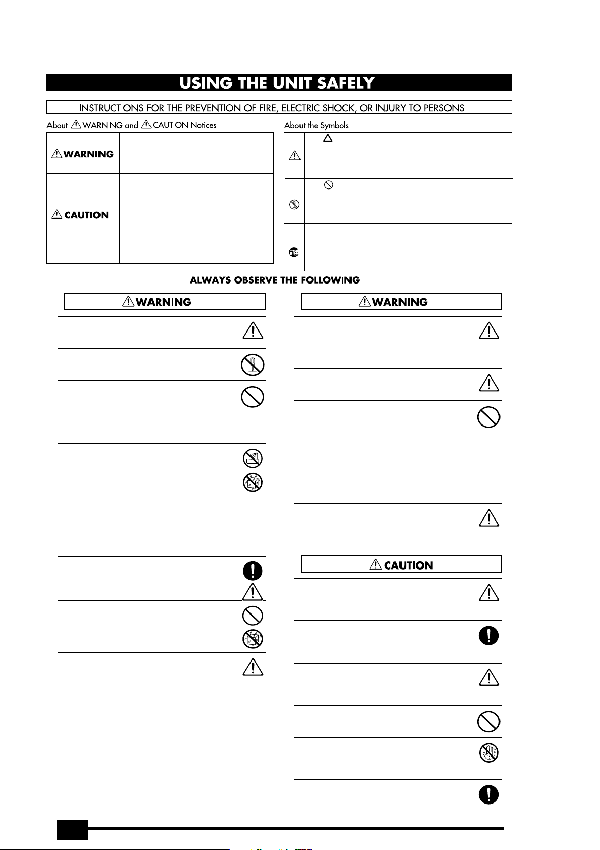
Used for instructions intended to alert
the user to the risk of death or severe
injury should the unit be used
improperly.
Used for instructions intended to alert
the user to the risk of injury or material
damage should the unit be used
improperly.
* Material damage refers to damage or
other adverse effects caused with
respect to the home and all its
furnishings, as well to domestic
animals or pets.
• Before using this instrument, make sure to read the
instructions below, and the Owner’s Manual.
• Do not open (or modify in any way) the instrument,
and avoid damaging an optional adapter.
• Do not attempt to repair the instrument, or replace
parts within it. Refer all servicing to your retailer, the
nearest Roland Service Center, or an authorized
Roland distributor, as listed on the “Information”
page.
• Never use or store the A-37 in places that are:
• Subject to temperature extremes (e.g., direct sun-
light in an enclosed vehicle, near a heating duct,
on top of heat-generating equipment); or are
• Damp (e.g., baths, washrooms, on wet floors); or
are
• Humid; or are
• Exposed to rain; or are
• Dusty; or are
• Subject to high levels of vibration.
The symbol alerts the user to important instructions
or warnings.The specific meaning of the symbol is
determined by the design contained within the
triangle. In the case of the symbol at left, it is used for
general cautions, warnings, or alerts to danger.
The symbol alerts the user to items that must never
be carried out (are forbidden). The specific thing that
must not be done is indicated by the design contained
within the circle. In the case of the symbol at left, it
means that the unit must never be disassembled.
The ● symbol alerts the user to things that must be
carried out. The specific thing that must be done is
indicated by the design contained within the circle. In
the case of the symbol at left, it means that the powercord plug must be unplugged from the outlet.
• In households with small children, an adult should
provide supervision until the child is capable of following all the rules essential for the safe operation
of the unit.
• Protect the instrument from strong impact.
Do not drop it!
• When using an optional adaptor, do not force it to
share an outlet with an unreasonable number of
other devices. Be especially careful when using
extension cords—the total power used by all devices
you have connected to the extension cord’s outlet
must never exceed the power rating (watts/amperes)
for the extension cord. Excessive loads can cause the
insulation on the cord to heat up and eventually
melt through.
• Before using the instrument in a foreign country,
consult with your retailer, the nearest Roland Service
Center, or an authorized Roland distributor, as listed
on the “Information” page.
• When using an optional adaptor, make sure the line
voltage at the installation location matches the
input voltage specified on the name plate.
• Do not allow any objects (e.g., flammable material,
coins, pins); or liquids of any kind (water, soft drinks,
etc.) to penetrate the instrument.
• Immediately turn the power off, remove the adaptor
from the outlet, and request servicing by your
retailer, the nearest Roland Service Center, or an
authorized Roland distributor, as listed on the “Information” page when:
• Objects have fallen into, or liquid has been spilled
onto the instrument; or
• The instrument has been exposed to rain (or oth-
erwise has become wet); or
• The instrument does not appear to operate nor-
mally or exhibits a marked change in performance.
2
• The instrument and the optional adaptor should be
located so their position does not interfere with their
proper ventilation.
• Whenever the instrument is to remain unused for an
extended period of time, disconnect the optional
adaptor if you have one.
• Try to prevent cords and cables from becoming
entangled. Also, all cords and cables should be placed
so they are out of the reach of children.
• Never climb on top of, nor place heavy objects on
the instrument.
• Never handle the batteries or optional adaptor with
wet hands when plugging into, or unplugging from,
an outlet or the A-37.
• Before cleaning the A-37, turn off the power and
unplug the optional adaptor from the outlet.
Page 3

r
Important notes
In addition to the items listed under “USING THE UNIT SAFELY” (page 2), please read and observe the following:
A-37
Power supply
• The A-37 can be operated using batteries or an optional adaptor. Be careful to insert the batteries the right way around. If
you prefer to use an adaptor, be sure to purchase a Roland
ACA model.
• Before connecting the A-37 to other devices, turn off the
power to all units. This will help prevent malfunctions and/or
damage to other devices.
Placement
• Using the A-37 near power amplifiers (or other equipment
containing large power transformers) may induce hum. To
alleviate the problem, change the orientation of this instrument; or move it farther away from the source of interference.
• This instrument may interfere with radio and television reception. Do not use it in the vicinity of such receivers.
• Do not expose the A-37 to direct sunlight, place it near
devices that radiate heat, leave it inside an enclosed vehicle,
or otherwise subject it to temperature extremes. Excessive
heat can deform or discolor the instrument.
Maintenance
• For everyday cleaning wipe the A-37 with a soft, dry cloth or
one that has been slightly dampened with water. To remove
stubborn dirt, use a mild, non-abrasive detergent. Afterwards,
be sure to wipe the instrument thoroughly with a soft, dry
cloth.
• Never use benzene, thinners, alcohol or solvents of any kind,
to avoid the possibility of discoloration and/or deformation.
Repairs and data
• Please be aware that all data contained in the instrument’s
memory may be lost when it is sent for repairs. Important
data should always be backed up via MIDI (see p. 12). In certain cases (such as when circuitry related to memory itself is
out of order), we regret that it may not be possible to restore
the data. Roland assumes no liability concerning such loss of
data.
Additional precautions
• Please be aware that the memory contents can be irretrievably lost as a result of a malfunction, or the improper operation of the instrument. To protect yourself against the risk of
losing important data, we recommend that you periodically
save a backup copy of important data in the instrument’s
memory.
• Use a reasonable amount of care when using the instrument’s
buttons, other controls, and jacks/connectors. Rough handling
can lead to malfunctions.
• Never strike or apply strong pressure to the display.
• When connecting/disconnecting MIDI cables, grasp the connector itself—never pull on the cable. This way you will avoid
causing shorts, or damage to the cable’s internal elements.
• A small amount of heat will radiate from the instrument during normal operation. This is perfectly normal.
• When you need to transport the instrument, package it in the
box (including padding) that it came in. Otherwise, you will
need to use equivalent packaging materials, or a flightcase.
Contents
Important notes. . . . . . . . . . . . . . . . . . . . . . . . . . . . . 3
1. The A-37 in a nutshell . . . . . . . . . . . . . . . . . . . . . 4
2. Panel descriptions . . . . . . . . . . . . . . . . . . . . . . . . . 5
3. The basics . . . . . . . . . . . . . . . . . . . . . . . . . . . . . . . . 6
3.1 Inserting or replacing the batteries . . . . . . . . . . . . . . . 6
3.2 Connecting an optional AC adaptor. . . . . . . . . . . . . . . 6
3.3 Connecting the A-37 . . . . . . . . . . . . . . . . . . . . . . . . . . .6
3.4 Powering up . . . . . . . . . . . . . . . . . . . . . . . . . . . . . . . . . . .7
4. Keyboard modes . . . . . . . . . . . . . . . . . . . . . . . . . . 8
5. Configuring the A-37 . . . . . . . . . . . . . . . . . . . . . . 9
5.1 Selecting the parameter to be edited. . . . . . . . . . . . . .9
5.2 CONTROL parameters . . . . . . . . . . . . . . . . . . . . . . . . . .10
5.3 DATA parameters . . . . . . . . . . . . . . . . . . . . . . . . . . . . . .11
5.4 PRG CHG parameters . . . . . . . . . . . . . . . . . . . . . . . . . .14
6. Miscellaneous. . . . . . . . . . . . . . . . . . . . . . . . . . . . 16
6.1 Transpose . . . . . . . . . . . . . . . . . . . . . . . . . . . . . . . . . . . .16
6.2 About MIDI Thru . . . . . . . . . . . . . . . . . . . . . . . . . . . . . .16
6.3 Working with Patches. . . . . . . . . . . . . . . . . . . . . . . . . .16
6.4 Restoring the factory settings. . . . . . . . . . . . . . . . . . .17
6.5 Specifications . . . . . . . . . . . . . . . . . . . . . . . . . . . . . . . . .17
3
Page 4

Owner’s Manual
1. The A-37 in a nutshell
Four keyboard modes
The A-37’s semi-weighted 76-note keyboard can be
used in Layer, Split, and Whole modes.
Perfect control
The A-37 puts you in control of all things MIDI in
your keyboard rig. Velocity sensitivity, Aftertouch,
Modulation, and Pitch Bend are built in – and can be
set for the Upper and Lower sections independently.
Then there is also a DATA ENTRY slider that can be
assigned to any control change number between
CC00 and CC119. Finally, the A-37 sports connectors
for an optional Sustain foot switch and an expression pedal.
Of course, you can also transpose the Upper and
Lower sections – either in octave or semitone steps.
This would allow you, for instance, to play a meaningful bass line with your right hand and a solo part
with your left.
128 Patch memories
The A-37 comes with 128 Patch memories where
you can save almost all settings, plus the MIDI channels for the Upper and Lower sections, and Bank
Select/Program Change numbers to be transmitted
on both section channels (where applicable) whenever you select the Patch in question.
Once you have used up all 128 internal Patch memories and need even more setups, you can archive
your existing settings via MIDI (Bulk Dump function).
Important note
When using an AC adaptor, use only the specified
device (Roland ACA series). Use of any other AC
adaptor could result in damage, malfunction or
electric shock.
Two independent MIDI loops and sequencer control
The A-37 comes with two MIDI OUT sockets (A and
B). By assigning an “A” channel (1A~16A) to the
Upper and/ or Lower section, you tell the A-37 to
transmit the related note and other MIDI messages
to its MIDI OUT A socket. Select a “B” channel
(1b~16b) if you wish to control a separate MIDI rig
via MIDI OUT B.
You can also set the tempo for an external
sequencer and store that value in a Patch – along
with the setting that specifies whether such messages should be transmitted to the MIDI OUT A or B
socket – or both.
Supports Roland’s GS Format
The GS Format is a standardized set of specifications
for Roland’s sound sources which defines the manner in which multitimbral sound modules will
respond to MIDI messages. All devices compatible
with the GS Format bear the GS logo. Every module
or instrument bearing the GS logo will respond in
the same way to the MIDI messages sent from the
A-37.
All Roland GS sound modules also fully support
Level 1 of the General MIDI System. The A-37 is also
GM2-compatible.
4
Page 5
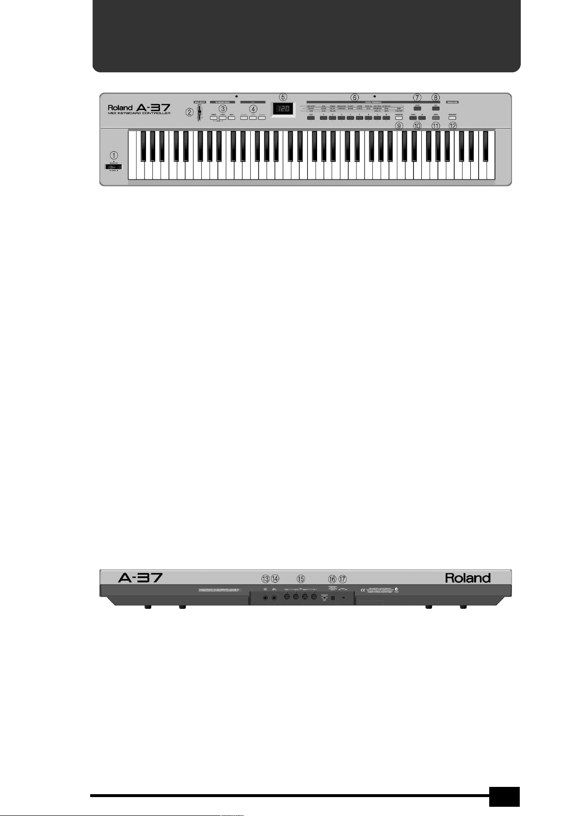
2. Panel descriptions
A
BENDER/MODULATION lever
Use this lever to transmit Pitch Bend (left/right
movements) or Modulation messages (CC01, movements towards the back of the A-37).
B
DATA ENTRY slider
This slider can be used to transmit the assigned MIDI
messages in realtime.
C
KEYBOARD MODE buttons
Press one of these buttons to select a Whole mode,
or the Layer or Split mode. See page 8.
D
EDIT buttons
Press one of these buttons ([CONTROL], [DATA], or
[PRG≈CHG]) to select the corresponding EDIT level.
You can then use the numeric keypad to call up the
parameter you wish to set.
E
Display
This three-character display keeps you posted about
the selected Patch memory, the tempo, or the
parameter value you set.
F
A/B button, numeric keypad (PATCH/PARAMETER)
If none of the EDIT buttons lights, the buttons [A/B]
and [1]~[8] allow you to enter the number of the
desired Patch memory (two banks of 64 memories
each). After pressing one of the EDIT buttons, the
buttons [A/B], [1]~[8] and [TRANSPOSE] (which then
functions as [9]) can be used for selecting the
desired parameter (see p. 9).
r
G
ENTER button
Press this button to confirm a setting or a selection.
H
EXIT button
Press this button to leave the currently selected EDIT
level, or to ignore the value you just set (thus
returning to the previously set value).
I
TRANSPOSE button
Usually, this button allows you to switch the A-37’s
keyboard transposition on and off and for setting
the transposition interval. When [CONTROL],
[DATA], or [PRG≈CHG] lights, however, this buttons
can be used for selecting a parameter (in which case
it functions as [9]).
J
DOWN/UP buttons
These buttons can be used for entering Patch memories, EDIT parameters, or parameter values. In certain cases, pressing them simultaneously will switch
the selected parameter on and off. Pressing them
simultaneously recalls the default value of the
selected parameter.
K
WRITE button
Press this button to save the current settings to one
of the A-37’s Patch memories. Writing a Patch also
involves pressing other buttons (see p. 16).
L
SEQUENCER [START/STOP] button
This button allows you to transmit MIDI Start and
Stop messages to start or halt playback of an external sequencer.
A-37
M
FOOT PEDAL socket
This is where you can connect an optional Roland
EV-5 or FV-300L expression pedal.
N
HOLD SWITCH socket
This is where you can connect an optional DP-2,
DP-6, or BOSS FS-5U footswitch to sustain the
notes you are playing (Hold, CC64).
O
MIDI THRU, OUT B, OUT A, IN sockets
Connect these sockets to the MIDI sockets of the
devices you wish to control, or the devices that
should transmit MIDI messages to the A-37.
P
DC IN socket
This is where you can connect an optional ACA
adaptor.
Q
POWER switch
Set this switch to the ON position to switch the
A-37 on. Select the OFF position to power off your
A-37.
5
Page 6
Owner’s Manual
3. The basics
3.1 Inserting or replacing the
batteries
The A-37 can be powered either by batteries or an
AC adaptor.
Battery replacement
Six AA batteries are required to run the A-37 on battery power. We recommend the use of alkaline batteries because they will provide a more stable, longlasting source of power. With alkaline batteries, you
can expect about 25 hours of continuous operation,
although this depends on how the A-37 is being
used.
Note: Avoid using new batteries together with old
ones. In addition, avoid mixing different types of batteries (e.g. regular carbon and alkaline batteries).
Note: When replacing batteries, be sure to insert them
correctly (ensure correct polarity).
Note: Remove the batteries whenever the A-37 is to
remain unused for an extended period of time.
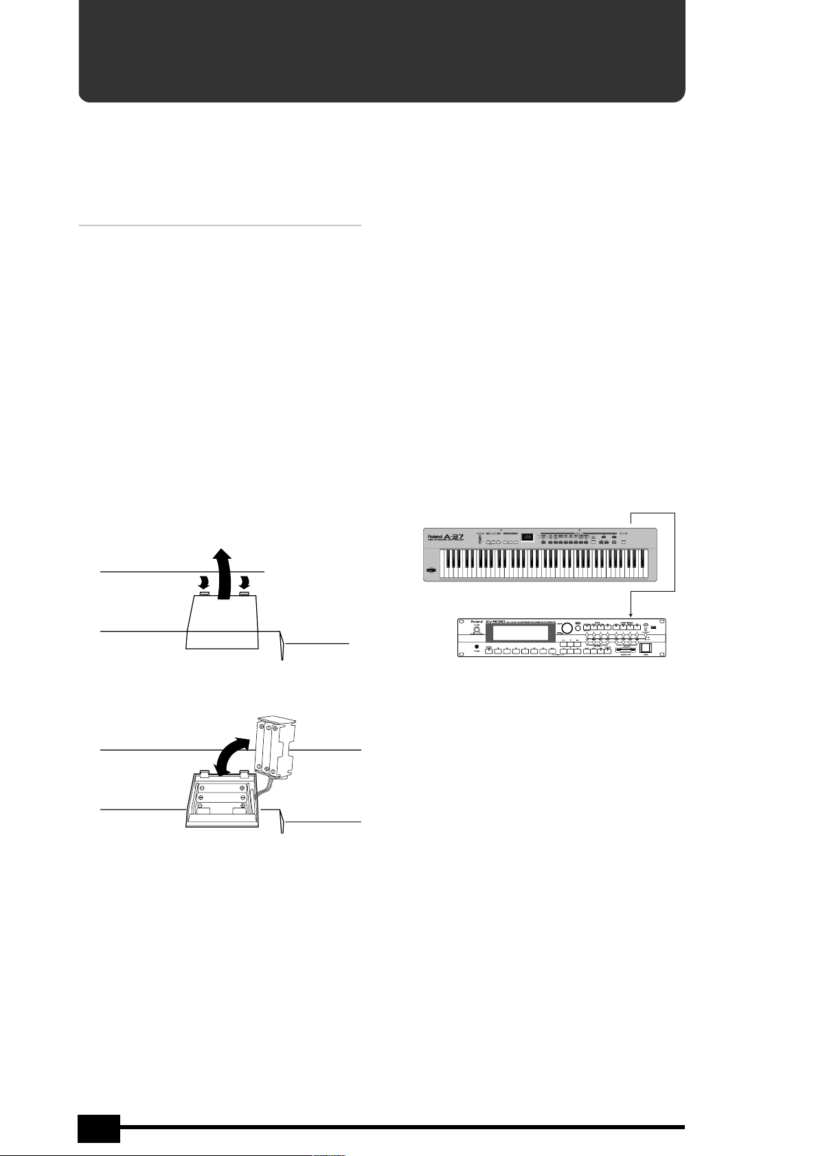
(1) Switch off the A-37.
(2) Remove the battery cover located on the bottom of
the instrument.
(b) Lift up.
(a) Press the tabs forward.
3.2 Connecting an optional AC
adaptor
Be sure to use only the specified AC adaptor (Roland
ACA series). Using any other type may cause malfunction or electric shock.
Note: If the A-37 is to remain unused for an extended
period of time, unplug the adaptor.
(1) Switch off the A-37.
(2) First connect the AC adaptor to the A-37’s DC IN
socket, then connect the large plug to a power outlet.
3.3 Connecting the A-37
Note: Switch off both the A-37 and the external
instrument(s) before establishing or breaking the MIDI
connections.
The A-37 is a MIDI controller. It contains no soundgenerating circuits of its own. You need to connect
it to at least one external MIDI instrument in order
to hear what you are playing. Here are the basic
connections:
MIDI OUT A or B
A-37 (transmits MIDI messages)
MIDI IN
(3) Take out the battery case, then insert the six batter-
ies supplied with the A-37 (three on either side).
(4) Insert the battery case and close the battery cover.
Module, synthesizer, etc. (receives MIDI messages)
Note: Do not forget to connect the module, synthesizer, etc., to an amplifier. See its manual for details.
6
Page 7
r
A-37
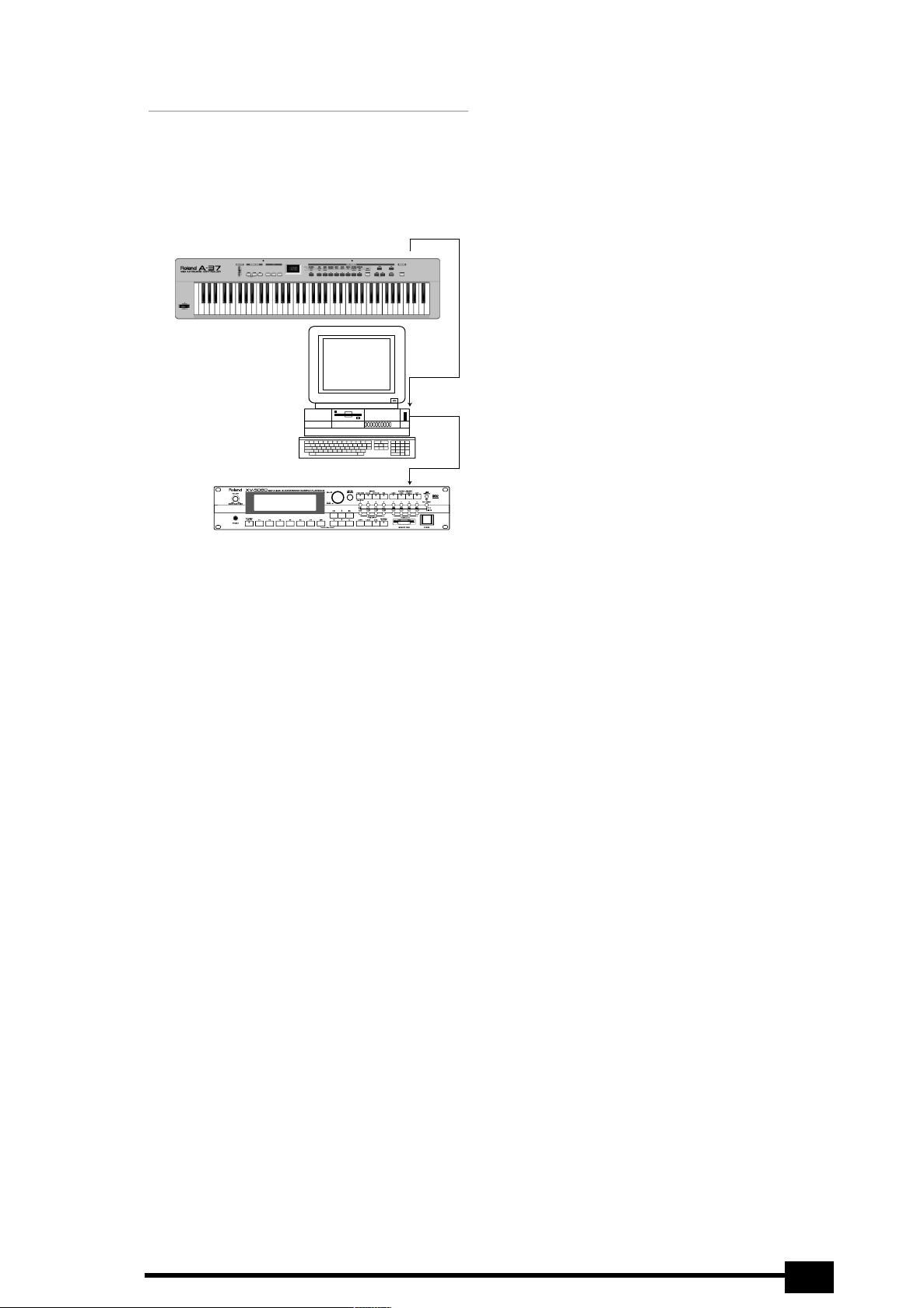
Working with a computer or sequencer
If you want to use the A-37 as Master keyboard for
recording applications that involve a computer with
sequencing software or a hardware sequencer (like
the Roland MC-80), here is the most useful connection system:
MIDI OUT A or B
A-37 (transmits MIDI
messages)
Computer or sequencer
(records and transmits
MIDI messages)
Module, synthesizer, etc. (receives MIDI messages)
MIDI IN
MIDI OUT
MIDI IN
3.4 Powering up
Power to the various devices should be turned on in
the appropriate order. First, turn on the units that
transmit MIDI messages (computer, A-37). Next,
turn on the sound module(s)/synthesizers, then the
amplification system.
Set the A-37’s power switch (rear panel) to the ON
position.
Power off your system in the reverse order.
Note: The A-37 is equipped with a circuitry protection
feature. At power-up, a brief interval is required before
it will operate normally.
Note: If the A-37 is powered using batteries, be sure to
switch it off whenever you are not planning to use it
for a while (5 minutes or more). But before doing so,
you may wish to save the current settings to a Patch
memory (see p. 16).
This setup only works as expected if the following
conditions are met:
• The computer (if that is what you use) must be
equipped with a MIDI interface.
• You need to switch on the sequencer’s MIDI Soft
Thru/MIDI Echo function. Otherwise you won’t hear
what you are playing. (See the sequencer’s/software’s manual for details.)
Note: The MIDI channel you set on the A-37 (see p. 11)
may be changed to another number by the sequencer.
If that is not the case, be sure to set at least one of the
A-37’s zones to the MIDI channel the module (not the
sequencer) is receiving on.
Note: Yet other configurations are possible, but the
above usually cover most of your MIDI needs. You
could connect the MIDI IN socket of a second module
to the a MIDI THRU socket of the module pictured
above for an even larger system.
Or you could establish the following connection:
[Sequencer] MIDI OUT → [A-37] MIDI IN
[A-37] MIDI THRU → [Module] MIDI IN
(Alternative: [A-37] MIDI OUT A → [Module] MIDI IN,
see also “About MIDI Thru” (p. 16)).
Note: It is also possible to use the A-37 MIDI OUT A
and MIDI OUT B sockets simultaneously for controlling
two separate MIDI chains.
7
Page 8
Owner’s Manual
4. Keyboard modes
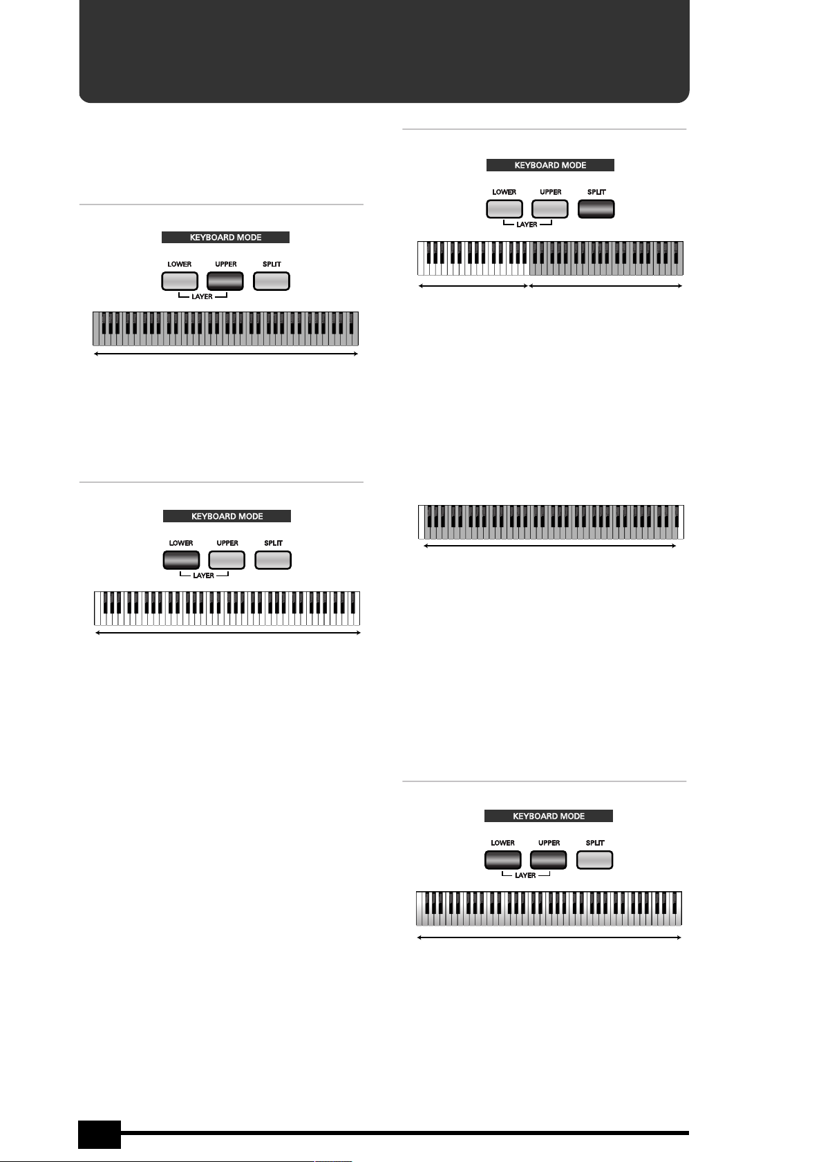
Your A-37 has three buttons that allow you to select
one of four Keyboard modes. The KEYBOARD MODE
determines how many zones and/or MIDI channels
can be used simultaneously.
Whole Upper
Upper section assigned to all keys
This mode means that the Upper section is assigned
to the entire keyboard. All messages generated on
the A-37 are therefore transmitted on the Upper
channel. Press the [UPPER] button to select this
mode.
Whole Lower
Split
Lower section Upper section
In Split mode, the Lower section is assigned to the
left half of the keyboard, while the Upper section is
assigned to the right. This allows you to control two
different MIDI instruments via separate channels
(Lower and Upper). Press the [SPLIT] button to select
this mode.
At first, the Split point is located at the “C” key
slightly left off center. This key is called the C4.
Here’s how to select another split point between the
“F1” and the “Gb7” (see the following illustration):
Lower section assigned to all keys
This mode means that the Lower section is assigned
to the entire keyboard. All messages generated on
the A-37 are therefore transmitted on the Lower
channel. Press the [LOWER] button to select this
mode.
Alternately pressing [UPPER] and [LOWER] allows
you to control different MIDI instruments as and
when needed. Example: you could use the Lower
section for controlling an organ sound of one module (or part), and the Upper section for playing a
lead synthesizer part using a different MIDI instrument.
Possible range for the Split point
(1) Press and hold the [SPLIT] button.
(2) While still holding that button, press the key that
should become the lowest note of the Upper section.
You can also use the [DOWN]/[UP] buttons.
(3) Release both the [SPLIT] button and the key you
pressed.
Note: This setting can be saved to a Patch. Your KEYBOARD MODE selection is also saved.
Note: To return to the default setting (C4), simultanesouly press [DOWN]/[UP].
Layer (Lower + Upper)
Lower section + Upper section (two different MIDI channels)
In Layer mode, the A-37 transmits on two MIDI
channels simultaneously (assigned to Lower and
Upper). Every action on the A-37 is thus translated
into two MIDI message strings. Hold down [LOWER]
while pressing [UPPER] to select this mode.
To leave it, press [LOWER], [UPPER], or [SPLIT].
8
Page 9
r
A-37
5. Configuring the A-37
Your A-37 comes with a great many MIDI parameters, or message types that can be transmitted so as to control your MIDI
rig to your liking. Most of the following parameters can be set for the Upper and Lower sections independently – and most
of them can be saved to a Patch memory (see p. 16).
Note: The available EDIT parameters will be presented
in the order they can be selected. See page 11 if all you
want to do for the time is being is assign different MIDI
channels to the Upper and/or Lower sections.
5.1 Selecting the parameter to be
edited
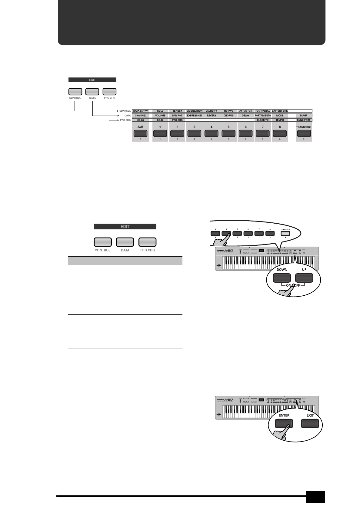
The A-37’s Edit parameters can be accessed via three
buttons:
Button Function
[CONTROL]
(page 10)
[DATA]
(page 11)
[PRG≈CHG]
(page 14)
When none of the above buttons lights, you are in
“play mode” (i.e. where you cannot change the
above parameters). That also means that the
numeric keypad ([A/B], [1]~[8]) can be used for
selecting Patch memories.
After pressing [CONTROL], [DATA], or [PRG≈CHG],
however, the buttons [0] (A/B) [1]~[8] and [9]
(TRANSPOSE) allow you to select the desired parameter. These numbers appear below the buttons and
are printed in orange (just like the EDIT button legends). See the illustration at the top of this page.
Provides access to all parameters related to
the available (or optional) performance
functions, like Pitch Bend, modulation,
Aftertouch, etc.
Provides access to more specific and static
MIDI parameters: transmit channel, volume,
etc., but also the Dump function.
Allows you to set and transmit memory
selection clusters (Bank Select, Program
Change), to set the MIDI tempo, and to
specify to which MIDI OUT socket to use for
these messages.
Here is how to select the desired parameter:
(1) Look at the legends above the [0]~[9] buttons to find
out which EDIT button you need to press.
(2) Press [CONTROL], [DATA], or [PRG≈CHG], depending
on the row that contains the desired parameter.
The number of the first parameter now flashes in
the display.
(3) Use the [0]~[9] buttons or [DOWN]/[UP] to select a
parameter.
After about three seconds, the display shows the
value currently set for the selected parameter.
(4) Press [LOWER] or [UPPER] to select the keyboard
section whose settings you wish to change.
Note: It is now no longer possible to select a different
KEYBOARD MODE. You need to leave the EDIT mode
altogether before being able to do that.
(5) Use [0]~[9] or [DOWN]/[UP] to make the desired set-
ting.
Some parameters can be set to 0FF. To do so, simul-
taneously press [UP] and [DOWN].
(6) Press [ENTER] to confirm the value or setting.
Press [EXIT] to return to the previous value.
(7) Press [EXIT] if you want to select another parameter
from the active EDIT group.
9
Page 10
Owner’s Manual
To select a parameter from a different group, press
the corresponding EDIT button ([CONTROL], [DATA],
[PRG≈CHG]), then return to step (3) above.
(8) Press [EXIT] yet again to leave the EDIT mode.
You will achieve the same result by pressing the
lighting EDIT button (it then goes dark).
Note: See page 16 if you wish to save the settings you
have just made as a Patch.
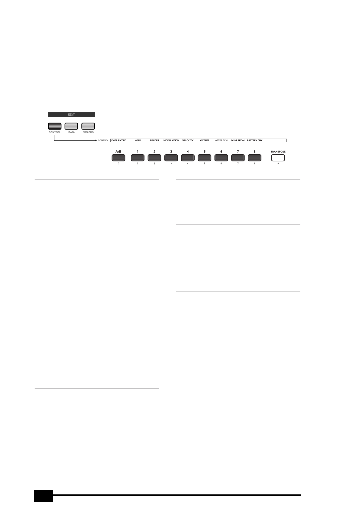
5.2 CONTROL parameters
As stated earlier, this is where you will find all parameters that are related to the A-37’s on-board or optional performance functions. This level also contains a parameter that allows you to check the state of the batteries.
[0] den (Data Entry)
This parameter allows you to assign a control
change number (CC) to the A-37’s [DATA≈ENTRY]
slider. The slider can then be used for realtime control of the related function. You can assign any
number between CC00 and CC119. Given their dedicated use for memory bank selection (see p. 14),
CC00 and CC32 are unlikely candidates for other
assignments. Assigning them to the [DATA≈ENTRY]
slider therefore makes little sense.
If you assign CC10 (Pan) to this slider, positions
below the center correspond to the left side, while
settings above the center correspond to the right.
Note: Certain MIDI instruments may not respond in
realtime to CC10 changes, because they only implement Pan changes at the beginning of a new note
(Note-on message).
It is also possible to select 0FF (by simultaneously
pressing [DOWN]/[UP]), which means that the
[DATA≈ENTRY] slider performs no function at all.
Note: See the manual of the MIDI instrument to be
controlled for the CC numbers it supports for realtime
control.
Note: The CC assignment can be different for the
Upper and Lower sections. This allows you, for example,
to control the Pan setting (CC10) via the Upper section,
and the Delay Send Level (CC94) via the Lower section.
[1] hld (Hold)
This parameter allows you to specify (for Upper and
Lower separately) whether the selected section
should (0N) or should not (0ff) transmit Hold
(CC64) messages. This is only relevant if you connect
an optional DP-2, DP-6, or BOSS FS-5U to the
A-37’s HOLD SWITCH socket.
Upper, Lower
Upper, Lower
[2] bnd (Pitch Bend)
This parameter allows you to specify whether the
selected section should (0N) or should not (0ff)
transmit Pitch Bend messages when you use the
A-37’s BENDER/MODULATION lever.
[3] mod (Modulation)
This parameter allows you to specify whether the
selected section should (0N) or should not (0ff)
transmit Modulation messages (CC01) when you use
the A-37’s BENDER/MODULATION lever.
CC01 messages can be used for creating vibrato,
tremolo, or WahWah effects. This depends on how
the receiving MIDI instrument uses these messages.
[4] Uel (Velocity)
This parameter allows you to assign a velocity curve
to the selected section. The A-37’s keyboard is
velocity sensitive and very responsive to nuances of
your playing. You may, however, be controlling a
MIDI instrument that does not interpret the velocity
values in the desired way. Rather than reprogram
the sound (if that is at all possible), you can simply
select another curve on the A-37 so that your striking force is translated in a different way and thus
more usable for the part you wish to play.
Select L (light) if the section in question should
send high velocity values even when you strike the
keys with light-to-medium force. M (medium) is the
default setting, which produces a natural response.
H (heavy), is the way to go if the external MIDI
instrument is too loud/bright when you play normally.
Select LL if all note messages of the section in
question are to be transmitted with more or less the
same velocity value. Extreme differences in dynamics (hitting very hard and very soft) will, however,
allow you to trigger velocity switches if the receiving MIDI instrument supports that feature. This setting is thus not the same as “off” on other instruments – but it is very similar.
Upper, Lower
Upper, Lower
Upper, Lower
10
Page 11
r
A-37
[5] oct (Octave)
This parameter is especially useful in Split mode (see
p. 8), when you wish to use your left hand for a
chord backing whose register is close to the part you
play with your right hand. Of course, you can also
transpose (or “shift”) the Upper part in octave steps,
which may be useful in Layer mode.
The setting range is –2, –1, 0, 1, 2 octaves (down or
up). Note that the A-37’s keyboard can also be
transposed in semitone steps. See page 16.
[6] aft (Aftertouch)
The A-37’s keyboard transmits channel Aftertouch
messages – if you want it to. Select 0n if the active
section should indeed do so. Select 0FF to keep a
section from transmitting Aftertouch messages.
Especially when working with a sequencer, it is usually wiser to select 0n only if you really want Aftertouch messages to be recorded. Aftertouch indeed
generates a continuous stream of values that take
up a lot of memory. If the receiving MIDI instrument
does not respond to them, it would be a good idea
not to transmit them in the first place.
Note: “Channel Aftertouch” refers to the fact that only
one Aftertouch value (the highest) is transmitted at
any one time, even though you may be playing chords.
Upper, Lower
Upper, Lower
[7] ftp (Foot Pedal/Expression)
This parameter allows you to specify whether the
selected section should (0n) or should not (0ff)
transmit expression (CC11) messages.
The third possibility, inU, is very interesting indeed
for the Layer mode (see p. 8): by assigning 0n to the
Upper section, and inU to the Lower section, for
example, you can increase the volume of the Upper
MIDI channel and simultaneously decrease that of
the Lower MIDI channel by pressing the pedal down
(toe down) – and vice versa. This allows for some
nifty “sound morphing”.
This parameter is only relevant if you connect an
optional EV-5 or BOSS FV-300L expression pedal to
the A-37’s FOOT PEDAL socket.
Upper, Lower
[8] bch (Battery Check)
This parameter allows you to check the voltage of
the batteries (0~100). The value “0” means that the
batteries should be dead by now, while “100” represents the highest value. A dot in the left part of the
display will flash whenever the battery power is less
than 30%.
Note: This value is only meaningful if no adaptor is
connected to the DC IN socket (if an adaptor is connected, the value will always be 100).
Note: For important occasions, it may be wiser to work
with an optional ACA adaptor. That way, you can rest
assured that you will not run into problems during the
session or gig.
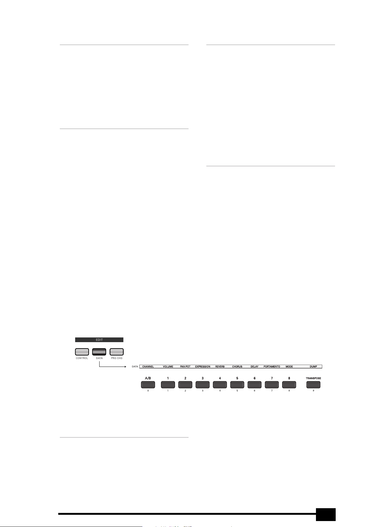
5.3 DATA parameters
The DATA parameters represent MIDI messages you can use for configuring the receiving MIDI instrument up to a certain point by specifying things like its main and expression volume, its Reverb and/or Chorus depth, etc.
These are “static” settings that are transmitted whenever you select a Patch. With the exception of ch, mde, and dmp,
the corresponding control change numbers can also be assigned to the DATA ENTRY slider for continuous realtime
control (see p. 10).
Note: Be sure to select 0FF for any MIDI message that
should not be transmitted.
Note: See page 9 for how to select and set these
parameters.
[0] ch (MIDI channel)
This parameter allows you to assign the desired MIDI
channel to the Upper or Lower section. In fact, this
parameter does two things at a time:
• it specifies the MIDI channel (1~16)
• it specifies the MIDI OUT socket via which the section’s MIDI messages are transmitted (A or B).
Upper, Lower
Here is an example: if you select 11b for the Upper
section, it will transmit its messages on MIDI channel “11” to MIDI OUT B. Though you can also select
0FF (by simultaneously pressing [DOWN]/[UP]),
there is little point in doing so. After all, you can
achieve the same result by switching off the KEYBOARD MODE button of the section you do not
need.
11
Page 12

Owner’s Manual
[1] Uol (Volume)
Upper, Lower
This parameter allows you to specify the volume
value (CC07) to be transmitted by the Upper and/or
Lower section whenever you select the Patch that
contains this setting. The setting range is 0~127,
Off. Remember that selecting “0” will silence the
receiving MIDI instrument.
Note: Even if you set this parameter to “127”, you will
hear nothing at all if you set EHP (see below) to “0”.
[2] pan (PanPot)
Upper, Lower
This parameter allows you to specify the Pan value
(CC10) to be transmitted by the Upper and/or Lower
section whenever you select the Patch that contains
this setting. The setting range is 0~127, Off. The
value “0” corresponds to hard left, “64” to the center,
and “127” to hard right.
Note: Some MIDI instruments work the other way
round (0= right/127= left). See the manual of the
instrument you are controlling for details.
[3] eHp (Expression)
Upper, Lower
This parameter allows you to specify the expression
value (CC11) to be transmitted by the Upper and/or
Lower section whenever you select the Patch that
contains this setting. The setting range is 0~127,
Off. Selecting “0” will silence the receiving MIDI
instrument. In most instances, you will probably
select 0FF or 127.
Note: Even if you set this parameter to “127”, you will
hear nothing at all if you set Uol (see above) to “0”.
Note: Not all MIDI instruments have a Chorus effect,
and even if they do, they may not support this control
change number (this is especially true of older instruments).
[6] del (Delay Send Level)
Upper, Lower
This parameter allows you to specify the Delay Send
Level value (CC94) to be transmitted by the Upper
and/or Lower section whenever you select the Patch
that contains this setting. The setting range is
0~127, Off. Selecting “0” will set the receiving MIDI
instrument to “dry” (no Delay), while “127” represents the maximum Delay Send level.
Note: If there is no audible change, you may have to
check the Delay effect settings on the receiving MIDI
instrument.
Note: Not all MIDI instruments have a Delay effect,
and even if they do, they may not support this control
change number.
[7] por (Portamento)
Upper, Lower
This parameter allows you to set two parameters
simultaneously: the Portamento switch (CC065) and
the Portamento time (CC05). By selecting a value
between “0” and “127”, the Portamento switch is
automatically set to “on” (127). If you set the Por
parameter to 0ff, however, the Portamento switch
(CC65) is turned off (0).
Portamento is an effect that produces gradual pitch
changes between the notes you play. The higher the
value, the longer it takes before the pitch of the
newly played note is reached.
[4] reU (Reverb Send Level)
Upper, Lower
This parameter allows you to specify the Reverb
Send Level value (CC91) to be transmitted by the
Upper and/or Lower section whenever you select the
Patch that contains this setting. The setting range is
0~127, Off.
Selecting “0” will set the receiving MIDI instrument
to “dry” (no Reverb), while “127” represents the
maximum Reverb Send level.
Note: If there is no audible change, you may have to
check the Reverb effect settings on the receiving MIDI
instrument.
Note: Not all MIDI instruments have a Reverb effect,
and even if they do, they may not support this control
change number (this is especially true of older instruments).
[5] cho (Chorus Send Level)
Upper, Lower
This parameter allows you to specify the Chorus
Send Level value (CC93) to be transmitted by the
Upper and/or Lower section whenever you select the
Patch that contains this setting. The setting range is
0~127, Off. Selecting “0” will set the receiving MIDI
instrument to “dry” (no Chorus), while “127” represents the maximum Chorus Send level.
Note: If there is no audible change, you may have to
check the Chorus effect settings on the receiving MIDI
instrument.
[8] mde (MIDI mode)
Upper, Lower
This parameter allows you to select the monophonic
(Mon) or polyphonic mode (Pol) on the receiving
MIDI instrument. Mono (CC126= 0) can come in
handy for solo lines based on special tricks (such as
not releasing one key, while pressing others in succession to create a “fast” line with little effort). If the
MIDI instrument should sound chords, however, be
sure to select Pol (CC127= 0).
[9] dmp (Bulk Dump)
This is not really a parameter but a function that
allows you to transmit the settings of the 128
Patches (see also page 16) to an external MIDI
instrument as SysEx data chunks. In most instances,
the recipient will be a sequencer.
Here is what you need to do in order to archive the
A-37’s settings:
(1) Switch off the A-37 and the sequencer.
12
Page 13
r
A-37
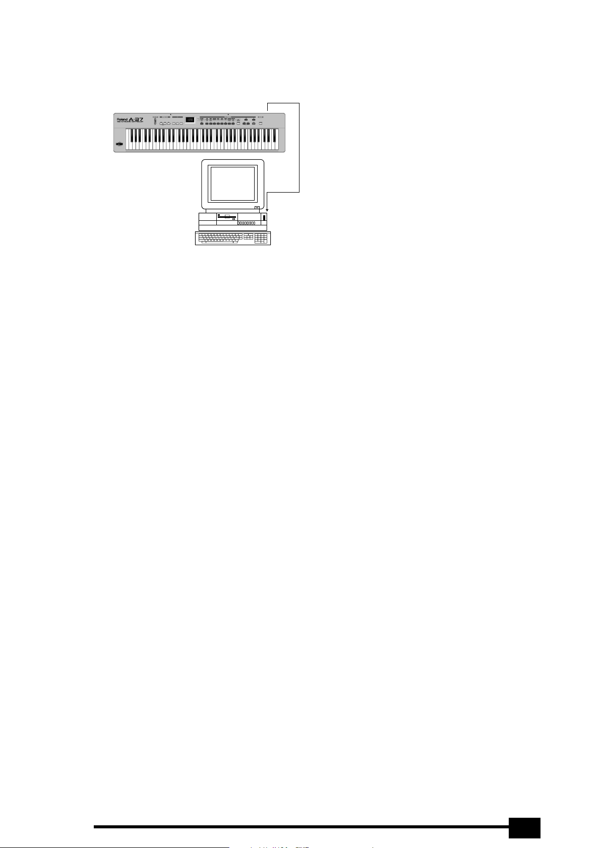
(2) Connect the sequencer’s MIDI IN socket to the
A-37’s MIDI OUT A socket.
MIDI OUT A
MIDI IN
The MIDI OUT B port cannot be used for this function.
(3) Switch on the A-37.
(4) Boot the sequencer and select an empty song. Then
activate its recording standby mode.
If the sequencer’s MIDI OUT socket is connected to
the A-37’s MIDI IN socket: on some sequencers, you
may have to temporarily defeat the Soft Thru/MIDI
Echo function.
(5) Select the dmp parameter by pressing [DATA], fol-
lowed by [9].
The display now shows Ent to signal that the A-37
is ready to transmit the data.
(6) Check whether the sequencer receives SysEx data
(see its manual), then start recording.
(7) Press the [ENTER] button on the A-37.
The display now counts down from 128 to 1 (thus
informing you about the Patch whose settings are
being transmitted).
(8) Wait until the Ent message reappears in the display,
then stop the sequencer’s recording function.
(9) Save the “song” (with the Bulk data) to hard disk or
floppy.
That file now contains your archive of the 128 Patch
memory settings.
The A-37 now once again contains the Patch settings contained in the archive.
Here’s how to retransmit such an archive from the
sequencer to the A-37 at a later stage:
(1) Switch off the A-37 and the sequencer.
(2) Connect the sequencer’s MIDI OUT socket to the
A-37’s MIDI IN socket. Switch on both devices.
(3) On the sequencer, load the “song” file that contains
the Bulk archive you wish to transmit to the A-37.
Warning: with the following step, you will erase the
128 Patches that currently reside in the A-37’s
internal memory. If you think you may need them at
a later stage, first archive them on the sequencer
(see above).
(4) Start playback on the sequencer.
As soon as the A-37 receives the first Bulk data, the
rH (RX) message appears.
(5) Wait until the rH message disappears, then stop
playback on the sequencer.
13
Page 14
Owner’s Manual
5.4 PRG CHG parameters
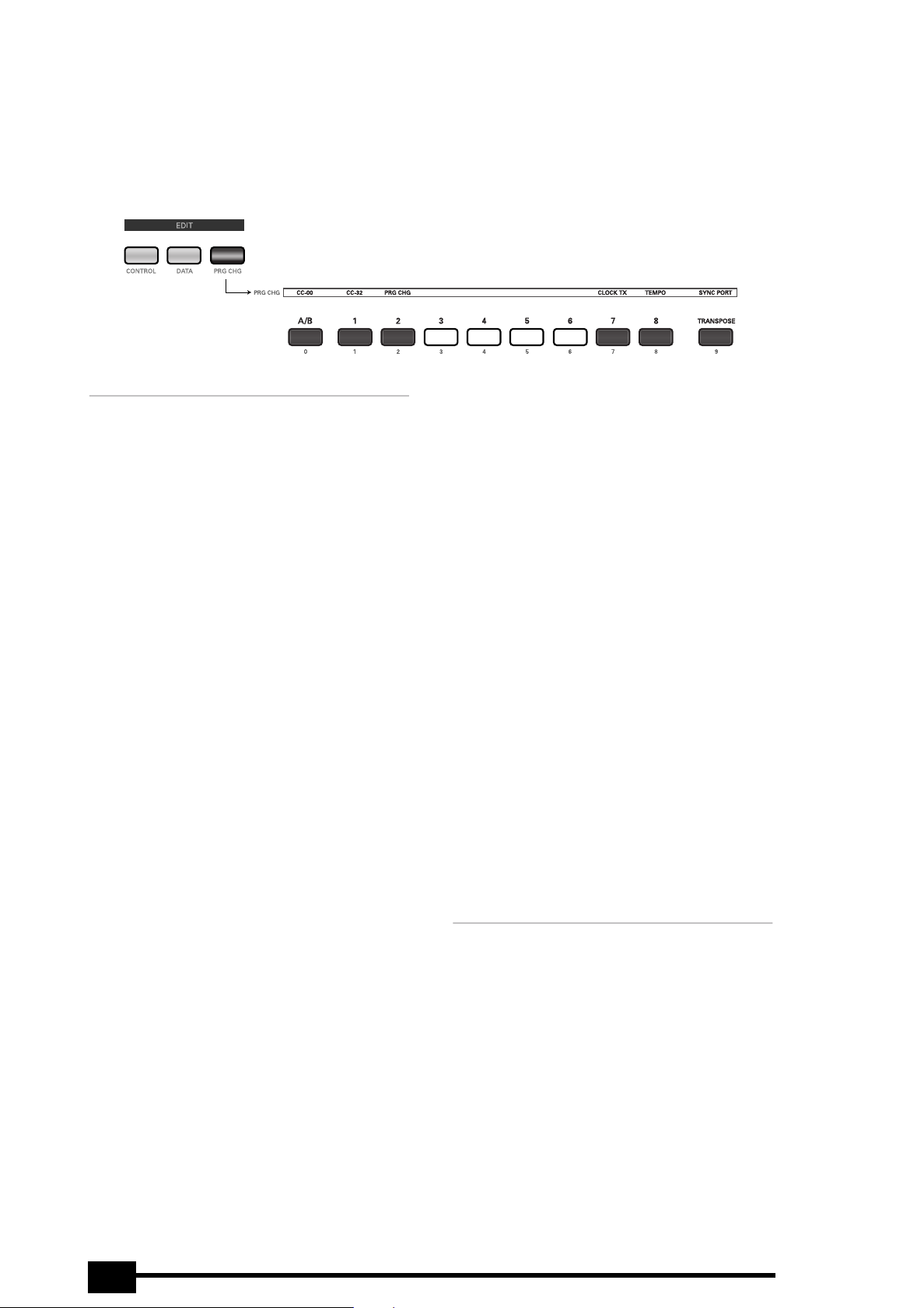
As can be inferred from the assigned buttons ([3]~[6] have no function), this EDIT level in fact consists of two groups:
the first three parameters can be set for both zones independently, while the last three apply to the A-37 as a whole.
Nevertheless, even these parameters are saved along with the remaining settings (see p. 16).
See page 9 for how to select and set these parameters.
[0] c00, [1] c32 (Bank Select messages)
[2] pc (Program Change)
Nowadays, most MIDI instruments and effects
devices contain a lot more than 128 sounds/memories. When the MIDI standard was developed, some
20 years ago, 128 memories seemed a lot, which is
why it was decided to use a dedicated message type
(Program Change) for selecting memories on an
external device.
The entire MIDI standard evolves around the magical number “128”. Given that there is no way of
expanding that number, so-called Bank Select messages were later added to accommodate the growing number of memories (synthesizers with more
than 2,000 sounds are quite common these days).
At the time, neither CC00, nor CC32 had dedicated
functions, and so these two control change messages were appointed Bank Select messages (by
Roland, by the way, with the introduction of its GS
Format).
Two bank addresses (MSB and LSB aka CC00 &
CC32) with 128 possibilities each, plus 128 Program
Change numbers provide 128 x 128 x 128 possibilities – a lot more than you can eat.
Mind you, nobody has even contemplated releasing
instruments with over 2 million memories, but at
least this system provides enough flexibility for
many years to come.
On the A-37, these three messages (CC00, CC32 and
Program Change) are always sent as a set. Transmitting only Bank Select messages does nothing at all,
while working only with Program Change messages
means that you are stuck with 128 memories in the
currently active memory bank.
That is why you need to transmit:
• A value for control change CC00 (MSB)
• A value for control number CC32 (LSB)
• A Program Change number
See the manual of the receiving MIDI instrument for
the MSB and LSB values it supports.
As soon as you press [ENTER] to confirm the Program Change number (after first entering and confirming the CC00 and CC32 values), the selected
section (Upper or Lower) immediately transmits the
Upper, Lower
memory selection cluster. If you save your settings
to a Patch, these values will also be memorized and
transmitted each time you select that Patch.
As you will notice, this procedure is very userfriendly indeed: after pressing [0] to select c00, and
entering the desired value for CC00, pressing
[ENTER] to confirm your setting will immediately
take you to [1], where you can enter the value for
CC32.
When you confirm that value by pressing [ENTER],
you can enter the Program Change number. (There is
thus no real need to press [1] or [2] to select the c32
and pc parameters).
As soon as you confirm the pc value (by pressing
[ENTER]), the memory selection cluster is transmitted to the MIDI OUT socket assigned to the active
section (A or B).
Note: While the setting range for CC00 and CC32 is
0~127, that of the pc parameter is 1~128.
Note: You can also select 0FF for these three parame-
ters to prevent the section in question from sending
that message.
Note: If pc is set to 0ff, the c00 and c32 are not
transmitted (CC00/CC32 must always be followed by a
Program Change number).
Note: These memory selection clusters can be programmed for the Upper and Lower sections individually.
[7] clt (MIDI Clock on/off)
This parameter (and the following two) allow you to
set the tempo and control playback of an external
sequencer.
With this parameter, you can specify whether (0n)
or not (0FF) the A-37 should transmit the MIDI
Clock messages set with the following parameter.
Selecting 0ff also means that the A-37 transmits
the MIDI Clock messages received via MIDI IN. This is
not the case if you select 0n, because then, the
A-37 transmits its own MIDI Clock signal.
Note: The A-37 is also capable of receiving MIDI Clock
messages and of retransmitting them to the MIDI OUT
A socket.
14
Page 15

[8] tmp (Tempo/BPM)
Here, you can set the tempo (MIDI Clock) to be
transmitted to an external sequencer. The setting
range is 20~250 BPM. This value will be transmitted
if clt is set to 0n.
[9] syp (Sync Port)
This parameter allow you to specify which MIDI OUT
socket to use for the transmission of MIDI Start/
Stop ([START/STOP] button) and MIDI Clock messages. The possibilities are: -A-, -B-, and A-B.
r
A-37
15
Page 16
Owner’s Manual
6. Miscellaneous
6.1 Transpose
Your A-37 comes with a TRANSPOSE function you
may want to use for playing songs in difficult keys.
To set the desired transposition interval:
(1) Hold down the [TRANSPOSE] button and wait until
the current transposition interval is displayed.
(2) Keep holding the [TRANSPOSE] button while you
press the key assigned to the note you wish to
assign to every C key (–6~5 semitones, i.e. from
Gb~G).
The [TRANSPOSE] indicator now lights steadily to
indicate that the Transpose interval has been set and
is being used.
You can also set the interval with the [DOWN]/[UP]
buttons. Pressing them simultaneously recalls the
default value (1).
(3) Once the desired interval has been set, you can
switch it off by pressing the [TRANSPOSE] button.
Press it again to switch the Transpose function back
on.
The button lights to indicate that the Transpose
interval is being used.
Note: The Transpose on/off setting applies to both keyboard sections (Upper and Lower) and can be saved to
a Patch memory.
6.2 About MIDI Thru
The A-37 has a MIDI THRU socket that retransmits
the messages received via its MIDI IN socket.
It can also merge the MIDI messages received via its
MIDI IN socket with the data generated on the A-37
itself, and retransmit the lot via its MIDI OUT A
socket.
6.3 Working with Patches
A “Patch” is a memory where you can store your
own settings. The A-37 provides 128 such memories
(in 2 banks of 64 memories).
Like on many Roland instruments, only 8 buttons
([1]~[8]) are used for specifying the Patch numbers
(11~88), so that numbers like “30” or “59” are
impossible. That explains why the 11~88 range adds
up to 64 possibilities (or memories). The bank can be
selected using the [A/B] button.
Storing settings in a Patch memory
After setting all parameters to your liking, you can
store them in one of the A-37’s Patch memories. If
you have spent a lot of time fine-tuning your settings, you should definitely store them before
switching off the A-37. It would also be a good idea
to save all settings your are satisfied with, even
though you may have to change them (or others) at
a later stage. You could then simply overwrite the
memory in question.
You can store everything in the A-37’s Patch memories except Dump (see p. 12) and Battery Check (see
p. 11).
All entries marked “Upper, Lower” are saved in duplicate: one set for the Lower section, and a second for
the Upper section.
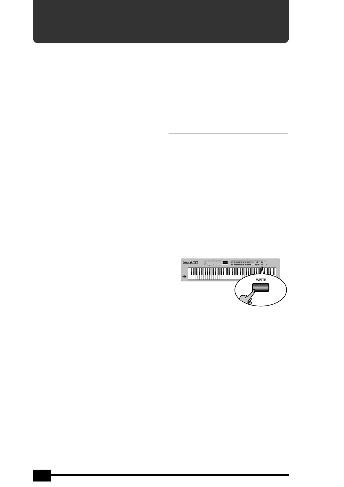
(1) Press and hold the [WRITE] button.
16
(2) Enter the address of the desired Patch memory by
pressing:
• [A/B] to select bank A or b (example: b--).
• [1]~[8] to select a bank (example: b5-)
• [1]~[8] to select a memory within that bank
(example: b57)
• Press [ENTER] to confirm your setting.
Note: You can release [WRITE] at any of these stages if
you do not wish to save the Patch after all.
The display shows the number of the Patch memory
that contains your new settings.
Note: The previous settings in the selected Patch
memory will be overwritten.
Note: In case of a power failure while you are saving a
Patch, the A-37 may display a scrolling message to the
effect of Patch a15 recoUered (or another number). This means that the Patch memory in question
(but only that one) has been reset to the factory settings for safety reasons. Your other Patches are fine,
however.
Page 17

r
A-37
Selecting Patches
(1) If you haven’t yet saved your current settings, do it
now (see above).
(2) Leave the currently selected EDIT mode by pressing
[CONTROL], [DATA], or [PRG≈CHG] (depending on
which of these buttons lights).
(3) Use the [A/B] and [1]~[8] buttons to select the
desired Patch memory.
You can also use [DOWN]/[UP]. If, after selecting
Patch b88, you press [UP] yet again, you return to
Patch A11. Conversely, if you press [DOWN] after
selecting Patch A11, you will go to Patch b88.
6.4 Restoring the factory settings
You can reset the A-37 to its factory settings, which
means that your own Patches will be overwritten
with the settings the A-37 contained when you first
got it. You may wish to archive your Patches before
initializing the A-37 (see p. 12).
Power on the A-37 while holding down the [WRITE]
button. The display will read factory Setup
(scrolling message) as soon as the factory settings
have been loaded.
See page 109 for a list of the A-37’s factory settings.
6.5 Specifications
Keyboard: 76 keys, velocity sensitive, with channel
Aftertouch
Display 3 x 7 segments
Realtime
controllers
Memories 128 Patches
Connections:
Compatibility:
Power
supply:
Dimensions: 1195 (W) x 270 (D) x 113 (H) mm
Weight: 7.7 kg
Supplied
accessories:
Options: Roland ACA adaptor (9V, 200mA)
Note: Specifications are subject to changes without
prior notice.
Data Entry slider, Bender/Modulation lever,
channel Aftertouch, Hold Foot Switch
socket, Foot Pedal socket
MIDI In, Out A, Out B, Thru, Expression
Pedal, Sustain Footswitch, DC IN (adaptor)
GM/GM2/GS, all MIDI messages
Batteries, AC/DC adaptor (DC 9V)
6 x dry batteries (AA type), MIDI cable,
Owner’s Manual, Music Rest
DP-2, DP-6, or BOSS FS-5U footswitch
EV-5, Boss FV-300L expression pedal
17
Page 18

Owner’s Manual
18
 Loading...