

Page 1
WPC Qi-compliant Wireless Power Series
NFC-compatible Wireless Power Transmitter
for Automotive Applications
BD57121MUF-M Evaluation Board
BD57121MUF-EVK-001
Page 2
Notice
<High Voltage Safety Precautions>
◇ Read all safety precautions before use
Please note that this document covers only the BD57121MUF-M evaluation board
(BD57121MUF-EVK-001) and its functions. For additional information, please refer to
the datasheet.
To ensure safe operation, please carefully read all precautions before
handling the evaluation board
Depending on the configuration of the board and voltages used,
Potentially lethal voltages may be generated.
Therefore, please make sure to read and observe all safety precautions described in
the red box below.
Before Use
[1] Verify that the parts/components are not damaged or missing (i.e. due to the drops).
[2] Check that there are no conductive foreign objects on the board.
[3] Be careful when performing soldering on the module and/or evaluation board to ensure that solder
splash does not occur.
[4] Check that there is no condensation or water droplets on the circuit board.
During Use
[5] Be careful to not allow conductive objects to come into contact with the board.
[6] Brief accidental contact or even bringing your hand close to the board may result in
discharge and lead to severe injury or death.
Therefore, DO NOT touch the board with your bare hands or bring them too close to the board.
In addition, as mentioned above please exercise extreme caution when using conductive tools such as
tweezers and screwdrivers.
[7] If used under conditions beyond its rated voltage, it may cause defects such as short-circuit or,
depending on the circumstances, explosion or other permanent damages.
[8] Be sure to wear insulated gloves when handling is required during operation.
After Use
[9] The ROHM Evaluation Board contains the circuits which store the high voltage. Since it stores the
charges even after the connected power circuits are cut, please discharge the electricity after using
it, and please deal with it after confirming such electric discharge.
[10] Protect against electric shocks by wearing insulated gloves when handling.
This evaluation board is intended for use only in research and development facilities and
should by handled only by qualified personnel familiar with all safety and operating
procedures.
We recommend carrying out operation in a safe environment that includes the use of high
voltage signage at all entrances, safety interlocks, and protective glasses.
www.rohm.com HVA01E
© 2018 ROHM Co., Ltd. All rights reserved.
Page 3
© 2017 ROHM Co., Ltd.
No. 60AP001E Rev.001
2017.4
© 2019 ROHM Co., Ltd.
No. 61UG042E Rev.001
JAN.2019
User’s Guide
Parameter
Min
Typ
Max
Units
Conditions
Input voltage
11.0
12.0
13.0
V
Output voltage
(receiver side)
-
12.0
-
V
Using BD57015GWL-EVK-002
Rx board
Output current
(receiver side)
0 - 1.25
A
Using BD57015GWL-EVK-002
Rx board
Dark current
- 0 5
μA
SW1=OFF
Operating frequency
(Wireless power)
-
127.8
-
kHz
WPC Qi-compliant Wireless Power Series
NFC-compatible Wireless Power Transmitter
for Automotive Applications
BD57121MUF-M E valuation Board
BD57121MUF-EVK-001
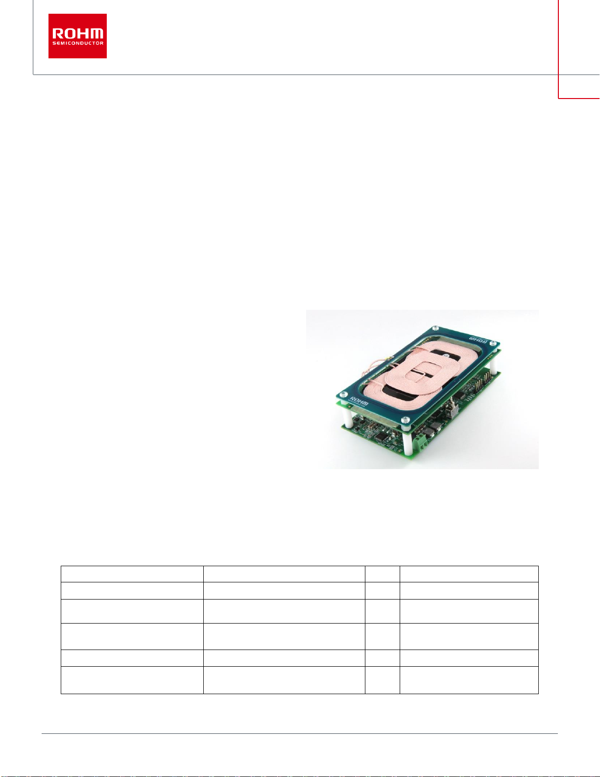
BD57121MUF-EVK-001 Evaluation Board is based on the BD57121MUF-M Automotive-grade wireless power transmitter IC. This board
integrates the ST25R3914 NFC reader/writer IC from ST Microelectronics to detect the presence of any NFC cards or tags and to prevent
damaging of the NFC antennae by the wireless power transfer system. Wireless power transfer is compliant with WPC Qi ver1.2.4 and can supply
power up to 15 W (output in receiver). Detection and identification of NFC Type A, B, F and V are possible.
Features
・Compliance to WPC Qi ver1.2.4
・Support of Multiple coils to increase charging area
(Qi MP-A13 coil type)
・Power control using fixed frequency and variable voltage
・NFC card / tag detection of Type A, B, F, V
・Housing size: 120 mm x 65 mm x 30 mm
Figure 1. BD57121MUF-EVK-001 Evaluation Board
Performance specification
These are only representative values, and they do not represent guaranteed values of the product characteristics.
VIN = 12 V, unless otherwise specified.
1/13
Page 4
User’s Guide
BD57121MUF-EVK-001
© 2019 ROHM Co., Ltd.
No. 61UG042E Rev.001
JAN.2019
Rectification
Mod/DeMod
LDO
Qi packet
Controller
Load
Predriver
Transmitter(Tx) : BD57121MUF-EVK-001
Qi Receiver(Rx)
Voltage
&
Current
Sensing
Power
BD57015GWL
Data
Data
Half/Full
Bridge
Demodulator
Tx
Controller
Voltage
&
Current
Sensing
MCU
BD57121MUF-M
NFC Reader/Writer
NFC
Card/TAG
Data
Data
NFC listener
Manufacturer
Product
Part Number
ROHM Semiconductor
Wireless Power Transmitter IC
BD57121MUF-M
ROHM Semiconductor
Low Dropout Regulator IC
BD00C0AWFP-C
Infineon Technologies
Buck-Boost DC/DC controller IC
TLD5190QV
ST Microelectronics
NFC Reader/Writer IC
ST25R3914
ST Microelectronics
Microcontroller
STM8AF62A8
TDK
Qi Transmitter Coil
WT1005690-12F2-A6-G1
ROHM Semiconductor
NFC Antenna
- (PCB pattern)
Evaluation Board
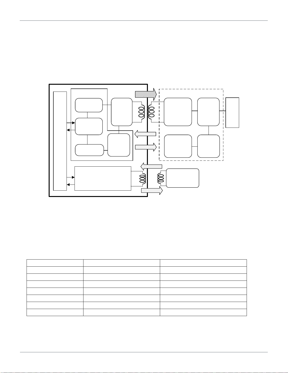
1. System configuration for wireless power transfer and NFC
Wireless power transfer system consists of a two-way power transmission and communication system using a transmitter and a
receiver, and the NFC system also communicates between the reader (= transmitter) and the listener. A single Microcontroller (MCU)
controls both wireless power transmission and NFC reader, so it is possible to have seamless operation between each other.
Figure 2. System configuration for wireless power transfer and NFC
2. Key components
The purpose of this EVK is to evaluate and verify key components needed for wireless power transfer and NFC detection. For more
information, refer to the Web site for each product.
2/13
Page 5
User’s Guide
BD57121MUF-EVK-001
© 2019 ROHM Co., Ltd.
No. 61UG042E Rev.001
JAN.2019
CAR Battery
LDO
Buck-Boost
DC/DC
5.4V/1A
Temperature
Sensing Circuits
(option)
Coil Selector
COIL1 COIL2 COIL3
Full Bridge
Qi Resonant Tank
ROHM WPT
BD57121MUF-M
ST Micro MCU
STM8AF
ST Micro
ST25R3914
DAC
V-
monitor
Pre-
drive
I-
monitor
FET FET
FET FET
LDO
I2C
(3.3V)
SPI
(3.3V)
3.3V/0.15A
12V/3A
Enable SW
Load SW
VDDMCU
VDDA
PI filter
VDDA
VDDMCU
VBUS54
VDDMCU
VBUS54
VDDMCU
VBUS54
NFC Antenna
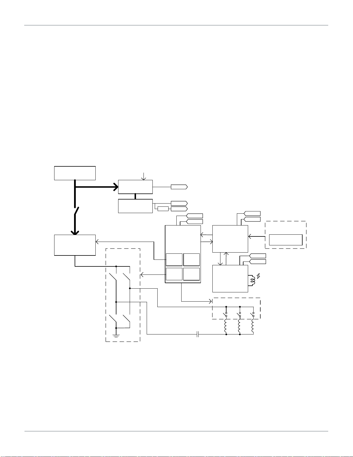
3. Block diagram of the transmitter
BD57121MUF-M operates with a 5.4 V power supply. NFC reader IC ST25R3914 operates with a main power supply of 5.4 V
and a sub of 3.3 V. The STM8AF MCU operates with a main power supply of 3.3 V. The peripheral voltage of the MCU is 3.3 V.
The MCU communicates with the BD57121MUF-M via I2C bus, and with the ST25R3914 via SPI bus.
BD57121MUF-M functions as the analog front-end for wireless power transfer that is compliant to Qi ver 1.2.4, and it includes a
D / A converter for voltage control, a pre-driver for driving the inverter bridge, an analog sensing circuit, and a selector circuit for
multiple coils.
ST25R3914 is a high-sensitivity and high-power NFC / HF analog front-end that supports ISO14443A / B, ISO15693, FeliCa™
and ISO 18092 (NFCIP-1) active P2P. This IC directly drives the NFC antenna. Please contact ST Microelectronics regarding
details of this IC.
Figure 3. BD57121MUF-EVK-001 Block diagram
3/13
Page 6

User’s Guide
BD57121MUF-EVK-001
© 2019 ROHM Co., Ltd.
No. 61UG042E Rev.001
JAN.2019
DC Power
Supply
+ -
SW1
Left : ON
Center: OFF
Right : OFF
LED indicators
Qi Coil
NFC Antenna
GNDADPVADPV
Operation Procedures
1. Required equipment
(1) 12V, 3A DC power supply
(2) BD57121MUF-EVK-001 Evaluation board (this EVK)
(3) Qi compliant receivers (Qi compliant Smartphone / Rohm's EVK receiver: BD57015GWL-EVK-002)
(4) Load (Electronic load or resistor is prepared as a load on the receiver side, if necessary)
(5) DC voltage meter
(6) NFC card / tag
2. Connecting the equipment
(1) Set the DC power supply to 12V and turn off the power supply output.
(2) Confirm that SW1 on the EVK is on the OFF side.
(3) Connect the positive terminal of the power supply to the ADPV terminal and the negative terminal of the power supply to the
GNDADPV terminal with a pair of wires.
(4) Turn on the DC power supply output.
(5) Set SW1 to ON, then LED4 lights on green.
Figure 4. Connection
4/13
Page 7

User’s Guide
BD57121MUF-EVK-001
© 2019 ROHM Co., Ltd.
No. 61UG042E Rev.001
JAN.2019
Tx Status
LED1(Green)
LED2(Green)
LED3(Red)
LED4(Green)
Disable (SW1=OFF)
OFF
OFF
OFF
OFF
Stand by(Idle)
OFF
OFF
OFF
ON
Qi BPP
(*1)
charging
ON
OFF
OFF
ON
Qi EPP
(*2)
charging
ON
ON
OFF
ON
During NFC detection
(*3)
OFF
OFF
ON
ON
During Error detection
(*4)
OFF
OFF
Blinking
ON
3. Operation of Wireless power transmission
(1) Put Qi compliant receiver directly on top of the Qi coil of the transmitter.
(2) When communication with the receiver is established, LED1 and LED2 light up in green according to the power profile of the
receiver.
(3) Connect the load.
4. Operation of NFC detection
(1) Place the NFC card / tag near the NFC antenna (approx. at 5 cm distance).
(2) LED3 lights on red during detection.
5. LED indicators
(*1) BPP (Baseline Power Profile): Capable wireless power supply up to 5W
(*2) EPP (Extended Power Profile): Capable wireless power supply up to 15W
(*3) LED3 also lights up when EVK protection circuit is activated.
Check whether there is abnormal heating on the board or overcurrent of the input power supply.
(*4) There are two types of error detection status.
・ Foreign Object Detection
Make sure that no foreign objects are caught between the transmitter and receiver.
In addition, due to position gap of the coil, foreign object may be detected. Therefore, please align the center of the
receiver coil with the center of Qi coil of the transmitter.
・ End of Power Transfer
The transmitter has stopped transferring power because it has received a stop signal from the receiver that is in use.
Please check using another receiver if the same phenomenon occurs.
5/13
Page 8

BD57121MUF-EVK-001
1
User’s Guide
Circuit Diagram 1
Figure 5. BD57121MUF-EVK-001 Circuit Diagram (1/2)
© 2019 ROHM Co., Ltd.
6/13
No. 61UG042E Rev.00
JAN.2019
Page 9

BD57121MUF-EVK-001
1
Circuit Diagram 2
User’s Guide
Figure 6. BD57121MUF-EVK-001 Circuit Diagram (2/2)
© 2019 ROHM Co., Ltd.
7/13
No. 61UG042E Rev.00
JAN.2019
Page 10

User’s Guide
BD57121MUF-EVK-001
© 2019 ROHM Co., Ltd.
No. 61UG042E Rev.001
JAN.2019
Instance Name
Value
Description
Size
Part Number/Series
Manufacturer
Quantity
U1
-
IC, WIRELESS TRANSMITTER
48VQFN
BD57121MUF-M
ROHM
1
U2
-
IC,IC LED DRVR DCDC CTRLR
48VQFN
TLD5190QV
INFINEON 1 U3
-
IC,IC REG LINEAR POS ADJ 1A
TO252-5
BD00C0AWFP-C
ROHM
1
U4
-
IC,IC MCU 8BIT 128KB FLASH
48LQFP
STM8AF62A8
STMICRO 1 U5
-
IC,IC REG LINEAR 3.3V 150MA
SOT23-5
TC1185-3.3VVCT713
MICROCHIP 1 U200
-
IC,NFC Initiator / HF Reader IC
QFN32
ST25R3914
STMICRO
1
Q_H1, Q_H2, Q_L1, Q_L2, Q5, Q13, Q14,
Q15, Q16
-
MOSFET Nch 40V 30A
HSMT8
RQ3G150GNMHSTB
ROHM
9
Q1
-
MOSFET Pch 30V 7A
TSTM8
RQ1E070RPFRATR
ROHM 1 Q2, Q12
-
MOSFET Nch 100V 1A
TSMT3
RSR010N10FHATL
ROHM 2 Q6, Q7, Q8
-
MOSFET Pch 60V 1.5A
TSMT3
RSR015P06FRATL
ROHM 3 Q9, Q10, Q11
-
MOSFET 2N-CH
8TDSON
IPG20N10S4L-35
INFINEON 3 D1
-
Diode,ZENER DIODES
EMD2
EDZVFHT2R36B
ROHM
1
D2, D4, D5, D6, D7, D8, D9, D13, D14
-
Diode,DIODE SCHOTTKY 100V
D_PMDU
RB578VYM100FHTR
ROHM 9 D10, D11, D12
-
Not mount
D_PMDU - - - LED1, LED2, LED4
-
LED, GREEN-YELLOW CLEAR
1006
SML-P11MTT86RG
ROHM
3
LED3
-
LED, RED CLEAR
1006
SML-P11VTT86RH
ROHM
1
L1
11.5 μH
Inductor, Qi Wireless 3 array coil
-
WT1005690-12F2-A6-G1
TDK
1
L2, L3
1 μH
Inductor 17.3A
-
ETQ-P4M1R0KVK
PANASONIC 2 L4
10 μH
Inductor, 7.6A
-
ETQ-P4M100KVC
PANASONIC 1 L5, L6
3.3 μH
Inductor, 6.1A
-
ETQ-P3M3R3KVN
PANASONIC 2 COM-CH1
700Ω
Inductor,CMC 5A 2LN
-
ACM90V-701-2PL-TL00
TDK 1 L7, L100, L101, L200
470Ω
Inductor, FERRITE BEAD
-
BLM18EG471SH1D
MURATA 4 L300, L301
180 nH
Inductor, 310mA, 1.65Ω
-
LQW18ANR18G8ZD
MURATA 2 RS1, RS2
0.1Ω
Resistor, Chip, 1/3W
1608
UCR10EVHFLR100
ROHM 2 RH1, RH2, RL1, RL2
10Ω
Resistor, Chip, 1/16W
1005
MCR01MZPD10R0
ROHM
4
RHD1, RHD2, RLD1, RLD2, RIN1, RIN2, R51,
R65, R91, R92, R93
100 kΩ
Resistor, Chip, 1/16W
1005
MCR01MZPD1003
ROHM
11
RTX
-
Not mount
1005 - - - RINVV, RINVI
22Ω
Resistor, Chip, 1/16W
1005
MCR01MZPD22R0
ROHM
2
RPK1
47 kΩ
Resistor, Chip, 1/10W
1608
MCR03EZPD4702
ROHM
1
RPK2
4.7 kΩ
Resistor, Chip, 1/10W
1608
MCR03EZPD4701
ROHM 1 RPUINTB, RPUSCL, RPUSDA
3.3 kΩ
Resistor, Chip, 1/16W
1005
MCR01MZPD3301
ROHM
3
RPUVAR, R21, R22, R23, RIN3, R74, R75
20 kΩ
Resistor, Chip, 1/16W
1005
MCR01MZPD2002
ROHM 7 R24, R25, R26
5.1 kΩ
Resistor, Chip, 1/16W
1005
MCR01MZPD5101
ROHM 3 R27, R28, R29, R55, R56
51 kΩ
Resistor, Chip, 1/16W
1005
MCR01MZPD5102
ROHM
5
R33, R34, R35
51Ω
Resistor, Chip, 1/10W
1608
MCR03EZPD51R0
ROHM
3
R41, R42
16 mΩ
Resistor, Chip, 1/3W
1608
UCR10PVHXFSR016
ROHM
2
R43
51Ω
Resistor, Chip, 1/16W
1005
MCR01MZPD51R0
ROHM 1 R44, R45
20 mΩ
Resistor, Chip, 1/3W
1608
UCR10PVHXFSR020
ROHM
2
R46
10 kΩ
Resistor, Chip, 1/16W
1005
MCR01MZPD1002
ROHM
1
R47
30 kΩ
Resistor, Chip, 1/16W
1005
MCR01MZPD3002
ROHM
1
RLSGD1, RLSGD2, RHSGD1, RHSGD2
0Ω
Resistor, Chip, 1/16W
1005
MCR01MZPJ000
ROHM
4
R52, R68, R97, R98, R99, RLED3, RLED4
1 kΩ
Resistor, Chip, 1/16W
1005
MCR01MZPD1001
ROHM
7
R53
3 kΩ
Resistor, Chip, 1/16W
1005
MCR01MZPD3001
ROHM
1
R54
24 kΩ
Resistor, Chip, 1/16W
1005
MCR01MZPD2402
ROHM 1 R58, RCLMP
100 kΩ
Resistor, Chip, 1/10W
1608
MCR03EZPD1003
ROHM
2
R59
510Ω
Resistor, Chip, 1/10W
1608
MCR03EZPD5100
ROHM
1
R61
62 kΩ
Resistor, Chip, 1/16W
1005
MCR01MZPD6202
ROHM
1
R62
10 kΩ
Resistor, Chip, 1/16W
1005
MCR01MZPD1002
ROHM
1
R66
2.4 kΩ
Resistor, Chip, 1/10W
1608
MCR03EZPD2401
ROHM
1
R67
330 kΩ
Resistor, Chip, 1/10W
1608
MCR01MZPD3303
ROHM
1
R68
22 kΩ
Resistor, Chip, 1/16W
1005
MCR01MZPD2202
ROHM
1
R71
100Ω
Resistor, Chip, 1/10W
1005
MCR01MZPD1000
ROHM
1
R76
47 kΩ
Resistor, Chip, 1/16W
1005
MCR01MZPD4702
ROHM
1
R77
6.8 kΩ
Resistor, Chip, 1/16W
1005
MCR01MZPD6801
ROHM
1
R82
10 kΩ
Resistor, Chip, 1/10W
1608
MCR03EZPD1002
ROHM 1 ROSC11
1 MΩ
Resistor, Chip, 1/16W
1005
MCR01MZPD1004
ROHM 1 ROSC12
15Ω
Resistor, Chip, 1/16W
1005
MCR01MZPD15R0
ROHM 1 ROSC21
10 MΩ
Resistor, Chip, 1/10W
1608
MCR03EZPFX1005
ROHM 1 ROSC22
15Ω
Resistor, Chip, 1/10W
1608
MCR03EZPD15R0
ROHM 1 RLED1, RLED2
680Ω
Resistor, Chip, 1/16W
1608
MCR03EZPD6800
ROHM 2 RADP1
120 kΩ
Resistor, Chip, 1/16W
1005
MCR01MZPD1203
ROHM 1 RADP2
18 kΩ
Resistor, Chip, 1/16W
1005
MCR01MZPD1802
ROHM 1 R200, R201, R202, R203, R204
220Ω
Resistor, Chip, 1/16W
1005
MCR01MZPD2200
ROHM 5 R205, R206
1 kΩ
Resistor, Chip, 1/16W
1005
MCR01MZPD1001
ROHM 2 R300_NFCF, R301_NFCF
2Ω
Resistor, Chip, 1/10W
1608
MCR03EZPD2R00
ROHM
2
R300, R301
1 Ω
Resistor, Chip, 1/10W
1608
MCR03EZPD1R00
ROHM
2
Bill of materials
8/13
Page 11

User’s Guide
BD57121MUF-EVK-001
© 2019 ROHM Co., Ltd.
No. 61UG042E Rev.001
JAN.2019
Instance Name
Value
Description
Size
Part Number/Series
Manufacturer
Quantity
CPIF1, CVRAIL1, C42, C45, C48
20 μF
Capacitor, Chip, 25V
3126
GCM32EC71E226KE36L
MURATA
5
CPIF2, CPIF3, CADP1, CADP2, CVIN, C61
10 μF
Capacitor, Chip, 35V
3126
GCM32EC7YA106KA03L
MURATA 6 CIN1, C43, C46, C55, C63, C67
1.0 μF
Capacitor, Chip, 25V
1608
GCM188R71E105KA64D
MURATA 6 CLVAR, CLDO50, CLDO33
4.7 μF
Capacitor, Chip, 25V
2012
GCM21BC71E475KE36L
MURATA
3
CBOOT1, CBOOT2, C47, C51, C52, C56,
C64, C65, C91, C92, C93, CNRST
0.1 μF
Capacitor, Chip, 50V
1005
GRT155R71E104KE01#
MURATA
12
CCOILV2, C24, C25, C26
1000 pF
Capacitor, Chip, 250V
2012
GCM21A5C2E102JX01#
MURATA
4
CVREF33, CVREF41, CRS, C44, C50
2.2 μF
Capacitor, Chip, 25V
2012
GCM21BR71E225KA73L
MURATA 5 CVDDIO, CVDD
1.0 μF
Capacitor, Chip, 25V
1608
GCM188R71E105KA64D
MURATA 2 CVRAIL2, CVRAIL3, CISEN
0.1 μF
Capacitor, Chip, 50V
1005
GRT155R71E104KE01#
MURATA
3
CSER11, CSER12, CP1, CP2, CP3, CP4
0.1 μF
Capacitor, Chip, 450V
3216
GC332DD72W104KX01L
MURATA 6 CSR13, CSR14
-
Not mount
3216 - - - CVDAC, C21, C22, C23, C202
-
Not mount
1005 - - - CSW1, CSW2
-
Not mount
1608 - -
-
C53, C54
0.022 μF
Capacitor, Chip, 50V
1005
GRT155R71H223KE01D
MURATA 2 CLS1, CLS2, CHS1, CHS2
100 pF
Capacitor, Chip, 50V
1005
GRT1555C1H101JA02#
MURATA 4 C66
470 pF
Capacitor, Chip, 50V
1005
GRT1555C1H471JA02#
MURATA 1 C68
2200 pF
Capacitor, Chip, 50V
1608
GRT1885C1H222JA02#
MURATA 1 C69
0.022 μF
Capacitor, Chip, 50V
1005
GRT155R71H223KE01D
MURATA 1 C70
680 pF
Capacitor, Chip, 50V
1005
GRT1555C1H681JA02#
MURATA 1 C81, C82
0.47 μF
Capacitor, Chip, 10V
1005
GRT155R71A474ME01#
MURATA 2 COSC11, COSC12
10 pF
Capacitor, Chip, 100V
1005
GRT1555C2A100JA02D
MURATA 2 COSC21, COSC22
3.3 pF
Capacitor, Chip, 100V
1005
GRT1555C2A3R3CA02D
MURATA 2 C100
100 pF
Capacitor, Chip, 50V
1005
GRT1555C1H101JA02#
MURATA 1 C101, C208, C209, C210, C211
0.01 μF
Capacitor, Chip, 25V
1005
GRT155R71E103KE01#
MURATA 5 C102, C212, C213, C214
2.2 μF
Capacitor, Chip, 10V
1005
GRT155C71A225KE13D
MURATA 4 C200, C215
1.0 μF
Capacitor, Chip, 25V
1608
GCM188R71E105KA64D
MURATA 2 C201, C203
0.1 μF
Capacitor, Chip, 50V
1005
GRT155R71E104KE01#
MURATA 2 C204, C205, C316, C317
12 pF
Capacitor, Chip, 50V
1005
GRT1555C1H120JA02#
MURATA 4 C206, C207
8.2 pF
Capacitor, Chip, 50V
1005
GCM1555C1H8R2DA16D
MURATA 2 C300, C311
150 pF
Capacitor, Chip, 50V
1608
GRT1885C1H151JA02#
MURATA 2 C301, C310
10 pF
Capacitor, Chip, 100V
1005
GRT1555C2A100JA02#
MURATA 2 C302, C309
220 pF
Capacitor, Chip, 50V
1005
GRT1555C1H221JA02#
MURATA 2 C302_NFCF, C309_NFCF
120 pF
Capacitor, Chip, 50V
1005
GRT1555C1H121JA02#
MURATA 2 C304, C308
1200 pF
Capacitor, Chip, 50V
1608
GRT1885C1H122JA02#
MURATA 2 C303, C306
39 pF
Capacitor, Chip, 50V
1608
GRT1885C1H390JA02#
MURATA 2 C305, C307
39 pF
Capacitor, Chip, 50V
1608
GRT1885C1H390JA02#
MURATA 2 C314, C315
5.6 pF
Capacitor, Chip, 50V
1005
GCM1555C1H5R6BA16D
MURATA 2 C318, C319
27 pF
Capacitor, Chip, 50V
1005
GRT1555C1H270JA02#
MURATA 2 C320, C321
56 pF
Capacitor, Chip, 50V
1005
GRT1555C1H560JA02#
MURATA
2
OSC1
48 MHz
Oscillator, CRYSTAL, 8PF
3225
NX3225GA
EXS00A-CG07369
NDK
1
OSC2
-
Not mount
3225 - -
1
Y100
27.12 MHz
Oscillator, CRYSTAL, 6PF
2016
XRCGB27M120F3A00R0
MURATA
1
RVDDIO, ROSC10, ROSC20, CSER21,
CSER22, CSER23, CSER24
-
Jumper, SOLDER SHORT
JUMPER
- - -
-
J302, J303
0Ω
Resistor, Chip, 1/16W
1005
MCR01MZPJ000
ROHM
2
9/13
Page 12

User’s Guide
BD57121MUF-EVK-001
© 2019 ROHM Co., Ltd.
No. 61UG042E Rev.001
JAN.2019
Layout 1
Figure 7. Top silk screen, layout (Top View)
Figure 8. Bottom silk screen, layout (Top View)
Figure 9. TOP Layer layout (Top View)
10/13
Page 13

User’s Guide
BD57121MUF-EVK-001
© 2019 ROHM Co., Ltd.
No. 61UG042E Rev.001
JAN.2019
Layout 2
Figure 10. Middle Layer 1 layout (Top View)
Figure 11. Middle Layer 2 layout (Top View)
Figure 12. Bottom Layer layout (Top View)
11/13
Page 14

User’s Guide
BD57121MUF-EVK-001
© 2019 ROHM Co., Ltd.
No. 61UG042E Rev.001
JAN.2019
0
10
20
30
40
50
60
70
80
0 5 10 15
System Efficiency [%]
Output Power at Rx [W]
0
10
20
30
40
50
60
70
80
0 1 2 3 4 5
System Efficiency [%]
Output Power at Rx [W]
Reference Application data
Figure 13. System Efficiency vs POUT (EPP)
Rx: BD57015GWL-EVK-002(ROHM), 12V output
Figure 14. System Efficiency vs POUT (BPP)
Rx: BD57011AGWL (ROHM), 5V output
12/13
Page 15

© 2019 ROHM Co., Ltd.
No. 61UG042E Rev.001
JAN.2019
User’s Guide
BD57121MUF-EVK-001
date
Revision
Changes
16. Jan. 2019
001
New release
Revision history
13/13
Page 16

Notes
The information contained herein is subject to change without notice.
1)
Before you use our Products, please contact our sales representative
2)
tions :
Although ROHM is continuously working to improve product reliability and quality, semicon-
3)
ductors can break down and malfunction due to various factors.
Therefore, in order to prevent personal injury or fire arising from failure, please take safety
measures such as complying with the derating characteristics, implementing redundant and
fire prevention designs, and utilizing backups and fail-safe procedures. ROHM shall have no
responsibility for any damages arising out of the use of our Poducts beyond the rating specified by
ROHM.
Examples of application circuits, circuit constants and any other information contained herein are
4)
provided only to illustrate the standard usage and operations of the Products. The peripheral
conditions must be taken into account when designing circuits for mass production.
The technical information specified herein is intended only to show the typical functions of and
5)
examples of application circuits for the Products. ROHM does not grant you, explicitly or implicitly,
any license to use or exercise intellectual property or other rights held by ROHM or any other
parties. ROHM shall have no responsibility whatsoever for any dispute arising out of the use of
such technical information.
The Products specified in this document are not designed to be radiation tolerant.
6)
For use of our Products in applications requiring a high degree of reliability (as exemplified
7)
below), please contact and consult with a ROHM representative : transportation equipment (i.e.
cars, ships, trains), primary communication equipment, traffic lights, fire/crime prevention, safety
equipment, medical systems, servers, solar cells, and power transmission systems.
Do not use our Products in applications requiring extremely high reliability, such as aerospace
8)
equipment, nuclear power control systems, and submarine repeaters.
ROHM shall have no responsibility for any damages or injury arising from non-compliance with
9)
the recommended usage conditions and specifications contained herein.
ROHM has used reasonable care to ensurH the accuracy of the information contained in this
10)
document. However, ROHM does not warrants that such information is error-free, and ROHM
shall have no responsibility for any damages arising from any inaccuracy or misprint of such
information.
Please use the Products in accordance with any applicable environmental laws and regulations,
11)
such as the RoHS Directive. For more details, including RoHS compatibility, please contact a
ROHM sales office. ROHM shall have no responsibility for any damages or losses resulting
non-compliance with any applicable laws or regulations.
When providing our Products and technologies contained in this document to other countries,
12)
you must abide by the procedures and provisions stipulated in all applicable export laws and
regulations, including without limitation the US Export Administration Regulations and the Foreign
Exchange and Foreign Trade Act.
This document, in part or in whole, may not be reprinted or reproduced without prior consent of
13)
ROHM.
and verify the latest specifica-
Notice
ZZZURKPFRP
652+0&R/WG$OOULJKWVUHVHUYHG
Thank you for your accessing to ROHM product informations.
More detail product informations and catalogs are available, please contact us.
ROHM Customer Support System
http://www.rohm.com/contact/
5
%
 Loading...