

Table 1
t
High Power Low Ohmic Chip Resistors<Wide Terminal type>
LTR10 (2012 size : 1 / 2W)
zFeatures
1) Improved welding strength
The structure of longer electrodes provides the wider welding area than the chip resistors with normal electrodes, and this
enhanced the solder welding strength.
2) Increased surge-resistance
This is achieved by Rohm’s original trimming technology plus resistive element patterning.
3) High-power tolerance
Two times of the rated power is guaranteed than the normal-electrode resistors.
4) ROHM resistors are ISO-9001 & ISO/TS16949 certified.
Design and specifications are subject to change without notice. Carefully check the specification sheet before using or
ordering it.
zApplications
Automotive, industrial and power supply.
zRatings
Item Conditions Specifications
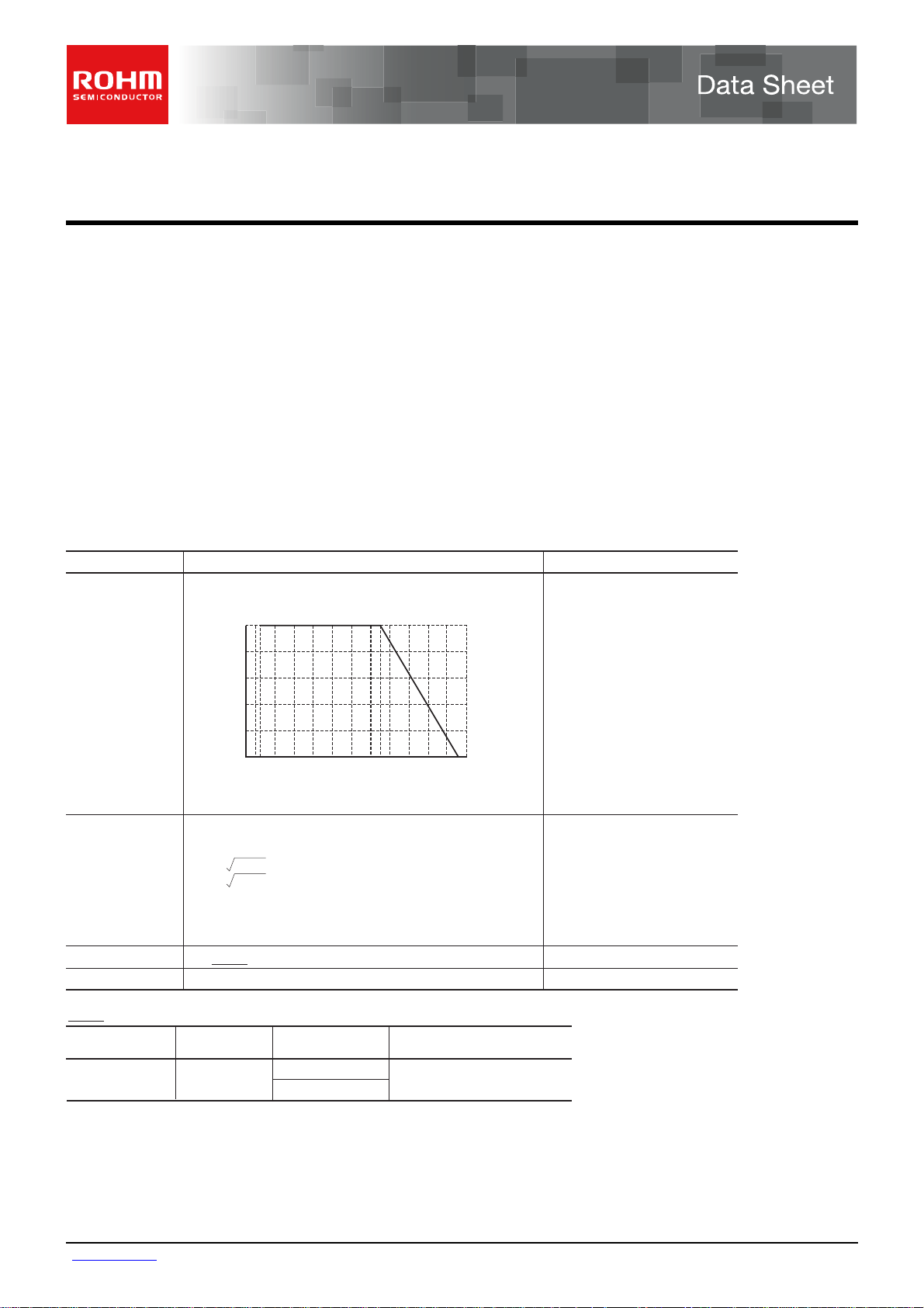
Rated power
Power must be derated according to the power derating curve in
Figure 1 when ambient temperature exceeds 70°
100
80
60
40
POWER LOAD (%)
20
0
−55 0 70 100 155
AMBIENT TEMPERATURE (°C)
Fig.1
C.
0.5W (1 /2W)
at 70°C
Rated voltage
Rated current
Nominal resistance
Operating temperature
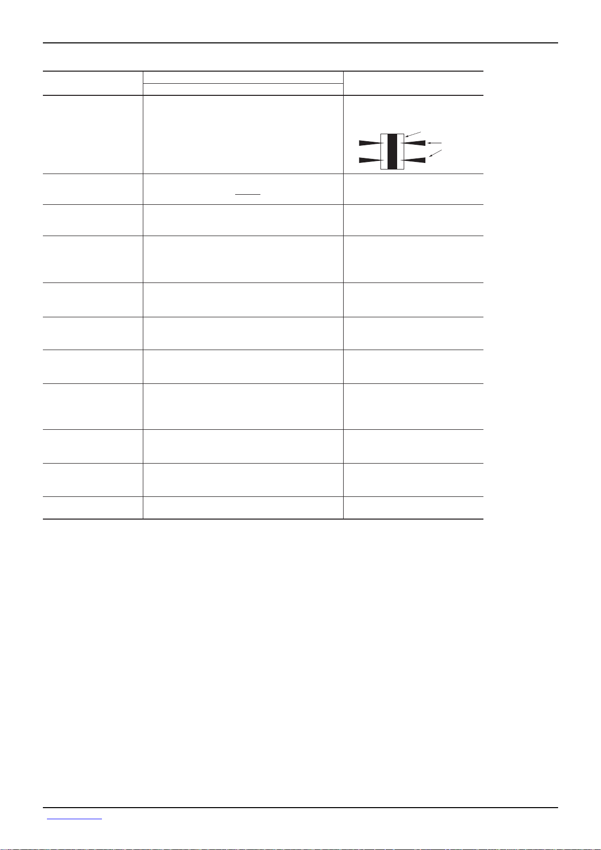
The voltage rating is calculated by the following equation.
E = P × R
I = P / R
See Table 1.
E : Rated voltage (V)
I : Rated current (A)
P : Rated power (W)
R : Nominal resistance (Ω)
C to + 155°C
−55°
Resistance range
(Ω)
0.047 to 9.1
Resistance
tolerance
F (±1%)
J (±5%)
Special part number
S
L
Resistance temperature coefficien
(ppm/°C)
±150
zBefore using components in circuits where they will be exposed to transients such as pulse loads (short–duration, high– level loads), be certain to evaluate the
component in the mounted state. In addition, the reliability and performance of this component cannot be guaranteed if it is used with a steady state voltage that
is greater than its rated voltage.
www.rohm.com
1/3
c
○
2009 ROHM Co., Ltd. All rights reserved.
2009.10 - Rev.B
s
n
.
Data Sheet LTR10
z
Characteristics
Item Test conditions (JIS C 5201-1)
Resistance
Variation of resistance
with temperature
Overload
Solderability
Resistance to
soldering heat
Rapid change of
temperature
Guaranteed value
Resistor type
JIS C 5201-1 4.5
Voltage : A
Measuring method : Measure under termination by 4 probe
F : ±1%
J : ±5%
See Table.1
± (2.0%+0.1Ω)
A new uniform coating of minimum of
95% of the surface being immersed
and no soldering damage.
± (1.0%+0.005Ω)
No remarkable abnormality on the appearance.
± (1.0%+0.005Ω)
JIS C 5201-1 4.8
Measurement : −55 / +25 / +125°C
JIS C 5201-1 4.13
Rated voltage (current) × 2.5, 2s.
JIS C 5201-1 4.17
Rosin·Ethanol (25%WT)
Soldering condition : 235±5
Duration of immersion : 2.0±0.5s.
JIS C 5201-1 4.18
Soldering condition : 260±5
Duration of immersion : 10±1s.
JIS C 5201-1 4.19
Test temp. : −55
Under terminatio
Terminal
°C
°C
°C
to +125°C 5cyc
Damp heat, steady state
Endurance at 70°C
Endurance
Resistance to solvent
Bend strength of
the end face plating
± (3.0%+0.005Ω)
± (3.0%+0.005Ω)
± (3.0%+0.005Ω)
± (0.5%+0.005Ω)
Without open.
JIS C 5201-1 4.24
°C, 93%RH
40
Test time : 1,000h to 1,048h
JIS C 5201-1 4.25.1
Rated voltage (current), 70
1.5h : ON − 0.5h : OFF
Test time : 1,000h to 1,048h
JIS C 5201-1 4.25.3
°C
155
Test time : 1,000h to 1,048h
JIS C 5201-1 4.29
°C
, Immersion cleaning, 5±0.5min
23±5
Solvent : 2-propanol
JIS C 5201-1 4.33
°C
www.rohm.com
2/3
c
○
2009 ROHM Co., Ltd. All rights reserved.
2009.10 - Rev.B

R
P
Data Sheet LTR10
zDimensions (Unit : mm)
a
R10
a
4
W
3
2
1
L
7
5
b
6
b
t
Size code L W t ba
2012 ( 0805)
1.2
± 0.1 0.3 ± 0.20.55 ± 0.1
2.0
± 0.1
0.35
± 0.2
z
Packaging
Reel Taping
ABD
0 2
0 4
0 6
0 8
C
ABCD
φ180
0
−1.5
φ60
+1
0
+1.0
9
0
Label
EIAJ ET-7200B compliant
(Unit: mm)
φ13±0.2
0 2
0 4
0 6
0 8
zPart No. Explanation
No.
1
Resistive element
2
Silver thick film electrode
3
Silver thick film side electrode
4
Nickel electrode
5
Sn electrode
6
Overcoating
7
Alumina substrate
Heat crimp cover/Tape
Thick paper
(Underside paper tape) Chip resistor Square punchout hole
mount
WFEA0 B0
8.0±0.3 3.5±0.05 1.75±0.1
D0 P0 P1 P2 T2
+0.1
4.0±0.1 4.0±0.1 2.0±0.05 Max. 1.1
φ1.5
0
P0
P2 P1
Material
A0
φD0
1.65
+0.2
−0.1
F
(Unit: mm)
+0.2
2.4
−0.1
E
W
T
2
TLR10
Part No.
E V H JS
Resistance tolerance
±
±
J
Special part number
1%F
5%
0.011 to 0.091 Ω
S
0.1 Ω
L
Nominal resistance
Resistance code, 3 or 4 digits.
Resistance
tolerance
FS, FL, JSJL::4 digits
Resistance
code
3 digits
ackaging Specifications Code
Part No.
eel (φ180mm) : Compatible with JEITA standard "EIAJ ET-7200B"
: Standard product
Code Packaging specifications Reel
EVH Paper tape (4mm Pitch) φ180mm (7inch)LTR10
Resistance tolerance
F(±1%) J(±5%)
Basic ordering unit
(pcs)
5,000
www.rohm.com
3/3
c
○
2009 ROHM Co., Ltd. All rights reserved.
2009.10 - Rev.B
Notes
No copying or reproduction of this document, in part or in whole, is permitted without the
consent of ROHM Co.,Ltd.
The content specied herein is subject to change for improvement without notice.
The content specied herein is for the purpose of introducing ROHM's products (hereinafter
"Products"). If you wish to use any such Product, please be sure to refer to the specications,
which can be obtained from ROHM upon request.
Examples of application circuits, circuit constants and any other information contained herein
illustrate the standard usage and operations of the Products. The peripheral conditions must
be taken into account when designing circuits for mass production.
Great care was taken in ensuring the accuracy of the information specied in this document.
However, should you incur any damage arising from any inaccuracy or misprint of such
information, ROHM shall bear no responsibility for such damage.
The technical information specied herein is intended only to show the typical functions of and
examples of application circuits for the Products. ROHM does not grant you, explicitly or
implicitly, any license to use or exercise intellectual property or other rights held by ROHM and
other par ties. ROHM shall bear no responsibility whatsoever for any dispute arising from the
use of such technical information.
Notice
The Products specied in this document are intended to be used with general-use electronic
equipment or devices (such as audio visual equipment, ofce-automation equipment, communication devices, electronic appliances and amusement devices).
The Products specied in this document are not designed to be radiation tolerant.
While ROHM always makes ef forts to enhance the quality and reliability of its Products, a
Product may fail or malfunction for a variety of reasons.
Please be sure to implement in your equipment using the Products safety measures to guard
against the possibility of physical injury, re or any other damage caused in the event of the
failure of any Product, such as derating, redundancy, re control and fail-safe designs. ROHM
shall bear no responsibility whatsoever for your use of any Product outside of the prescribed
scope or not in accordance with the instruction manual.
The Products are not designed or manufactured to be used with any equipment, device or
system which requires an extremely high level of reliability the failure or malfunction of which
may result in a direct threat to human life or create a risk of human injury (such as a medical
instrument, transportation equipment, aerospace machiner y, nuclear-reactor controller,
fuel-controller or other safety device). ROHM shall bear no responsibility in any way for use of
any of the Products for the above special purposes. If a Product is intended to be used for any
such special purpose, please contact a ROHM sales representative before purchasing.
If you intend to export or ship overseas any Product or technology specied herein that may
be controlled under the Foreign Exchange and the Foreign Trade Law, you will be required to
obtain a license or permit under the Law.
Thank you for your accessing to ROHM product informations.
More detail product informations and catalogs are available, please contact us.
ROHM Customer Support System
www.rohm.com
© 2009 ROHM Co., Ltd. All rights reserved.
http://www.rohm.com/contact/
R0039
A
 Loading...