

1/4
STRUCTURE Silicon Monolithic Integrated Circuit
TYPE Regulator IC for Memory termination
PRODUCT SERIES
BD3533HFN
FEATURES ・Incorporates a push-pull power supply for termination (VTT)
・Incorporates a reference voltage circuit(VREF)
・Compatible with Dual Channel (DDR-Ⅱ)
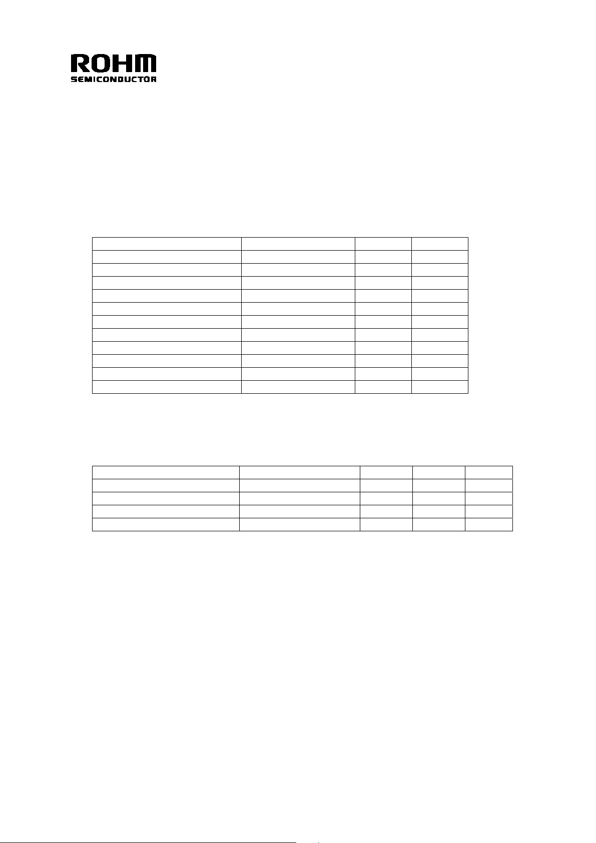
○ ABSOLUTE MAXIMUM RATINGS (Ta=100℃)
Parameter Symbol Limit Unit
Input Voltage VCC 7
Enable Input Voltage VEN 7
Termination Input Voltage VTT_IN 7
VDDQ Reference Voltage VDDQ 7
*1*2
V
*1*2
V
*1*2
V
*1*2
V
Output Current ITT 1 A
Power Dissipation1 Pd1 630 *3 mW
Power Dissipation2 Pd2 1350 *4 mW
Power Dissipation3 Pd3 1750 *5 mW
Operating Temperature Range Topr -30~+100 ℃
Storage Temperature Range Tstg -55~+150 ℃
Maximum Junction Temperature Tjmax +150 ℃
*1 Should not exceed Pd.
*2 Instantaneous surge voltage, back electromotive force and voltage under less than 10% duty cycle.
*3
With Ta≧25℃ when mounting a 70mm×70mm×1.6mm glass-epoxy substrate 1-layer board (copper foil density 0.2%) θja=198.4℃/W
*4 With Ta≧25℃ when mounting a 70mm×70mm×1.6mm glass-epoxy substrate 1-layer board (copper foil density 7%) θja=92.4℃/W
*5 With Ta≧25℃ when mounting a 70mm×70mm×1.6mm glass-epoxy substrate 1-layer board (copper foil density 65%) θja=71.4℃/W
○ RECOMMENDED OPERATING CONDITIONS (Ta=25℃)
PARAMETER SYMBOL MIN MAX UNIT
Input Voltage VCC 2.7 5.5 V
Termination Input Voltage VTT_IN 1.0 5.5 V
VDDQ Reference Voltage VDDQ 1.0 2.75 V
Enable Input Voltage VEN -0.3 5.5 V
★ No radiation-resistant design is adopted for the present product.
The Japanese version of this document is the official specification.
This translated version is intended only as a reference, to aid in understanding the official version.
If there are any differences between the original and translated versions of this document, the official Japanese language version takes priority.
REV. E
2/4
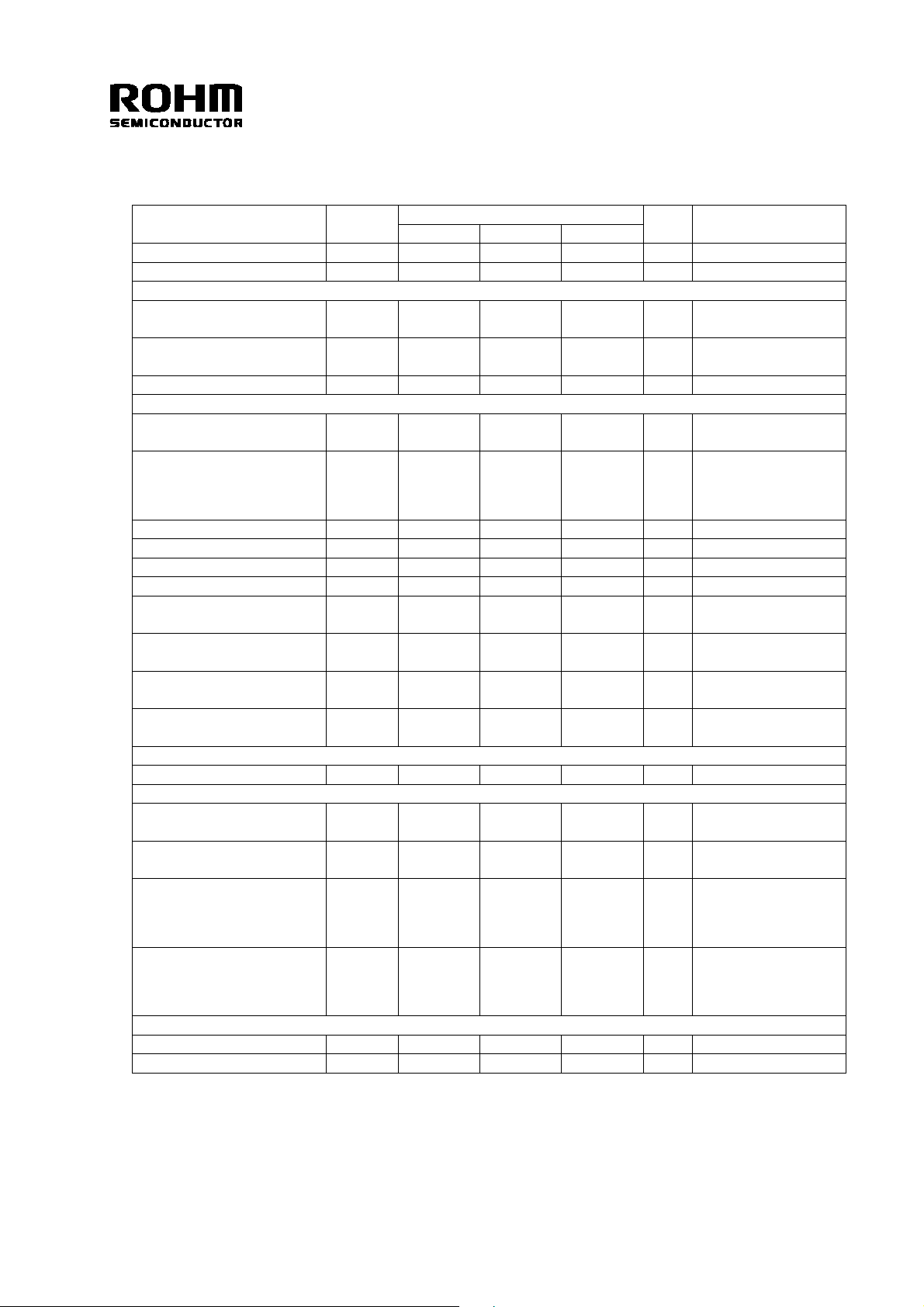
○ ELECTRICAL CHARACTERISTICS
(Unless otherwise specified,Ta=25℃ VCC=3.3V VEN=3V VDDQ=1.8V VTT_IN=1.8V)
PARAMETER SYMBOL
MIN TYP MAX
LIMIT
UNIT CONDITIONS
Standby Current IST - 0.5 1.0 mA VEN=0V
Bias Current ICC - 2 4 mA VEN=3V
[Enable]
High Level Enable Input
Voltage
Low Level Enable Input
Voltage
VENHIGH 2.3 - 5.5 V
VENLOW -0.3 - 0.8 V
Enable Pin Input Current IEN - 7 10 uA VEN=3V
[Termination]
Termination Output
Voltage 1
VTT1 VREF-30m VREF VREF+30m V
ITT=-1.0A to 1.0A
Ta=0℃ to 100℃
VCC=5V, VDDQ=2.5V
Termination Output
Voltage 2
VTT2 VREF-30m VREF VREF+30m V
VTT_IN=2.5V
ITT=-1.0A to 1.0A
Ta=0℃ to 100℃
Source Current ITT+ 1.0 - - A
Sink Current ITT- - - -1.0 A
Load Regulation ⊿VTT - - 50 mV ITT=-1.0A to 1.0A
Line Regulation Reg.l - 20 40 mV
Upper Side ON
Resistance 1
Lower Side ON
Resistance 1
Upper Side ON
Resistance 2
Lower Side ON
Resistance 2
HRON1 - 0.45 0.9 Ω
LRON1 - 0.45 0.9 Ω
HRON2 - 0.4 0.8 Ω
LRON2 - 0.4 0.8 Ω
Vcc=5V, VDDQ=2.5V
VTT_IN=2.5V
Vcc=5V, VDDQ=2.5V
VTT_IN=2.5V
[Input of Reference Voltage]
Input Impedance ZVDDQ 70 100 130 kΩ
[Reference voltage]
Output Voltage 1 VREF1
Output Voltage 2 VREF2
1/2×VDDQ
-18m
1/2×VDDQ
-40m
1/2×VDDQ
1/2×VDDQ
1/2×VDDQ
+18m
1/2×VDDQ
+40m
IREF=-5mA to 5mA
V
Ta=0℃ to 100℃
IREF=-10mA to 10mA
V
Ta=0℃ to 100℃
VCC=5V, VDDQ=2.5V
Output Voltage 3 VREF3
1/2×VDDQ
-25m
1/2×VDDQ
1/2×VDDQ
+25m
VTT_IN=2.5V
V
IREF=-5mA to 5mA
Ta=0℃ to 100℃
VCC=5V, VDDQ=2.5V
Output Voltage 4 VREF4
1/2×VDDQ
-40m
1/2×VDDQ
1/2×VDDQ
+40m
VTT_IN=2.5V
V
IREF=-10mA to 10mA
Ta=0℃ to 100℃
[UVLO]
UVLO OFF Voltage VUVLO 2.40 2.55 2.70 V VCC : sweep up
Hysteresis Voltage ⊿VUVLO 100 160 220 mV VCC : sweep down
*6
Design Guarantee
*6
*6
*6
*6
*6
*6
REV. E
 Loading...