

Motor driver ICs
Three-phase motor driver for
CD-ROMs
BA6858AFP / BA6858AFM / BA6859AFP /
BA6859AFP-Y / BA6859AFM / BA6859AFS
The BA6858A and BA6859A series are ICs developed for CD-ROM spindle motor drives. In addition to the functions
of the BA6849 series, (short brake, reverse-rotation prevention circuit, rotation direction dector, and FG output), the
BA6858A and BA6859A series have a built-in brake mode switching pin. With torque command input, these series are
compatible with the DSP3.3V. In addition, the BA6858A series has an FG composite output.
Applications
CD-ROM, CD-R, CD-RW, DVD-ROM, and DVD-RAM
Features
1) Three-phase, pseudo-linear drive system.
2) Built-in power save and thermal shutdown functions.
3) Built-in current limiter and Hall bias circuits.
4) Built-in FG output.
5) Built-in rotation direction detector.
6) Built-in reverse rotation prevention circuit.
7) Built-in short brake pin.
8) Built-in brake mode switching pin.
9) DSP3.3V compatible.
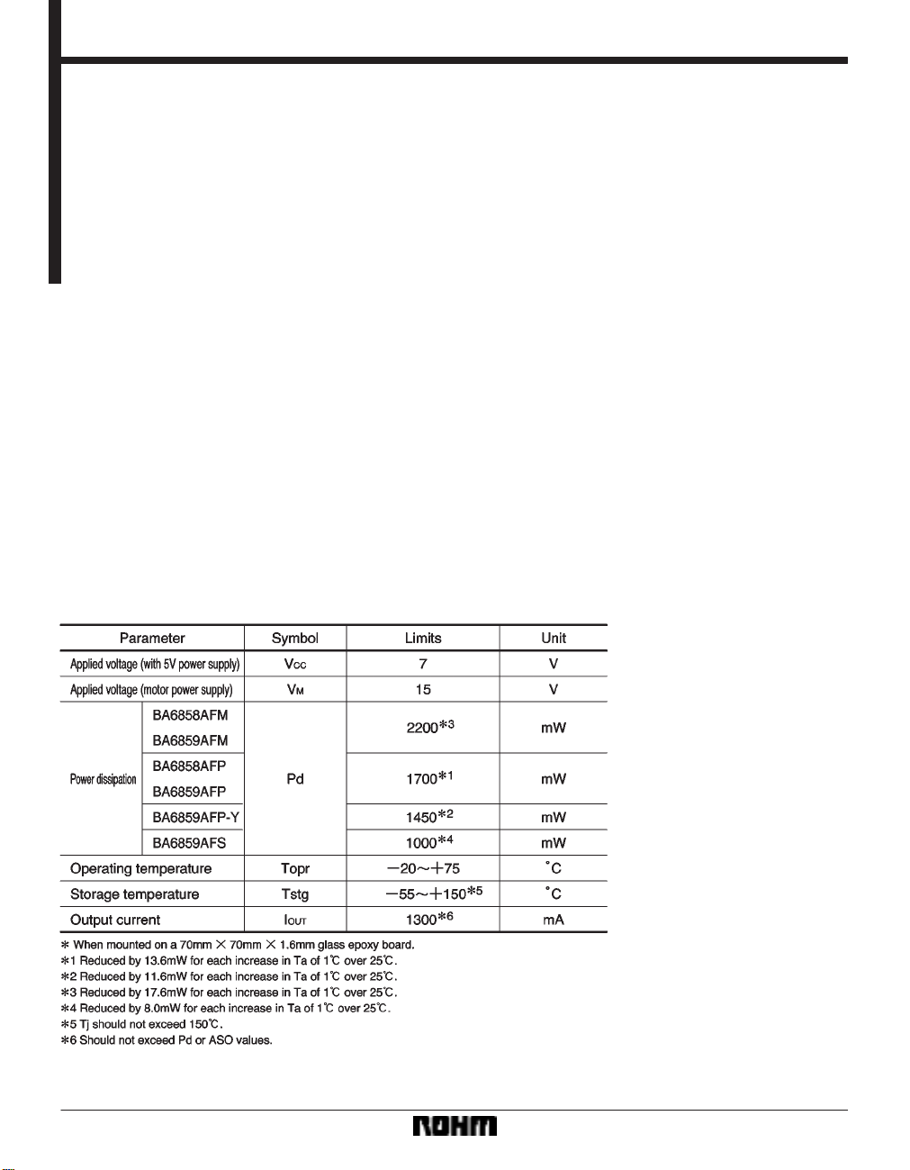
Absolute maximum ratings (Ta = 25C)
848
Mot
or driver ICs
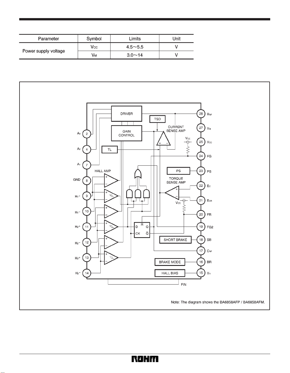
Recommended operating conditions (Ta = 25C)
Block diagram
BA6858AFP / BA6858AFM
BA6858AFP / BA6858AFM / BA6859AFP /
BA6859AFP-Y / BA6859AFM / BA6859AFS
849
Mot
or driver ICs
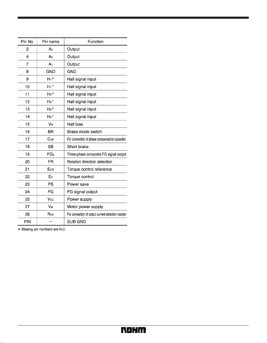
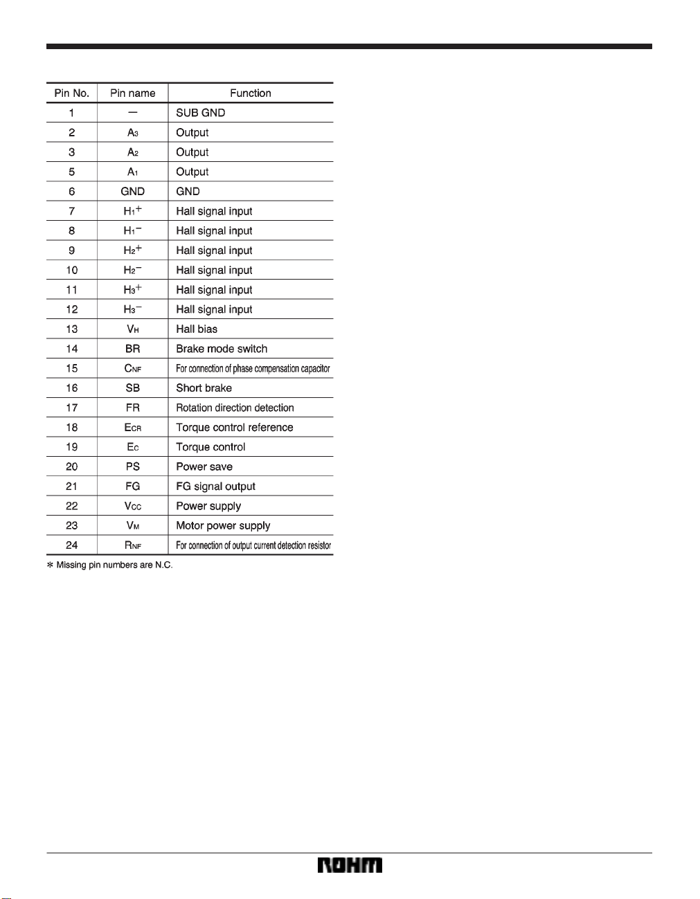
Pin descriptions
BA6858AFP/BA6858AFM
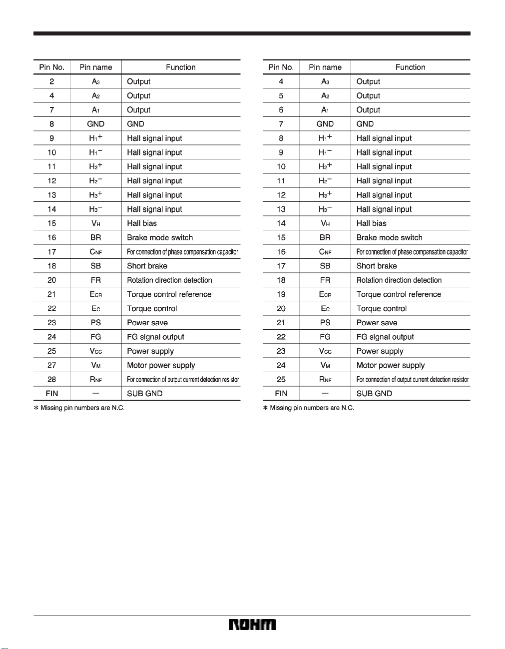
BA6858AFP / BA6858AFM / BA6859AFP /
BA6859AFP-Y / BA6859AFM / BA6859AFS
850
BA6858AFP / BA6858AFM / BA6859AFP /
Mot
or driver ICs
BA6859AFP/BA6859AFM BA6859AFP-Y
BA6859AFP-Y / BA6859AFM / BA6859AFS
851
Mot
or driver ICs
BA6859AFS
BA6858AFP / BA6858AFM / BA6859AFP /
BA6859AFP-Y / BA6859AFM / BA6859AFS
852

BA6858AFP / BA6858AFM / BA6859AFP /
Mot
or driver ICs
Input / output circuits
(1) Power save (2) Torque command input
BA6859AFP-Y / BA6859AFM / BA6859AFS
(3) Torque output (A
(4) Hall input (H
1
1, A2, and A3)
, H1, H2, H2, H3, H3)
853

Mot
or driver ICs
BA6858AFP / BA6858AFM / BA6859AFP /
BA6859AFP-Y / BA6859AFM / BA6859AFS
(5) Hall bias
(6) FG output
(7) FG2 Output
(8) FR output
(9) Short brake
854

Mot
or driver ICs
(10) Brake mode
BA6858AFP / BA6858AFM / BA6859AFP /
BA6859AFP-Y / BA6859AFM / BA6859AFS
Electrical characteristics (unless otherwise noted, Ta = 25C, V
CC = 5V, VM = 12V)
855

Mot
or driver ICs
BA6858AFP / BA6858AFM / BA6859AFP /
BA6859AFP-Y / BA6859AFM / BA6859AFS
856

BA6858AFP / BA6858AFM / BA6859AFP /
Mot
or driver ICs
Circuit operation
(1) Hall input to coil output
The phase relationship between the Hall input signals and the output current and voltage is shown in Fig.11. The motor
position data input via the Hall pins is amplified by the Hall amplifier, and formed into waveforms by the matrix block.
These signals are input to the output driver that supplies the drive current to the motor coils.
BA6859AFP-Y / BA6859AFM / BA6859AFS
857

Mot
or driver ICs
(2) Torque command
NF pin voltage with respect to the torque command (EC) is as follows:
The R
BA6858AFP / BA6858AFM / BA6859AFP /
BA6859AFP-Y / BA6859AFM / BA6859AFS
(3) Reverse rotation detection function
The reverse detection circuit construction is shown in
Fig.13.
(1) Forward (E
C < ECR)
The phase relationship between the Hall input signals
2
and H3 becomes as shown in Fig.11, and the re-
H
verse rotation detection circuit does not operate.
(2) Reverse (E
The phase relationship between the signals H
3
is opposite that for forward operation, and the re-
H
C > ECR)
2
and
verse rotation detection circuit operates. The output
goes OFF, and becomes open circuit.
The I / O gain (G
current) is determined by the R
EC = 0.35 / RNF (A / V)
G
EC) from the EC pin to the RNF pin (output
NF detector resistor.
The torque limit current ITL is given by:
TL = 0.35 / RNF (A)
I
858

Mot
or driver ICs
BA6858AFP / BA6858AFM / BA6859AFP /
BA6859AFP-Y / BA6859AFM / BA6859AFS
(4) Short brake
When 2.5V or more is applied to the short brake pin, the
top-side output transistors of all phases go off, and the
bottom-side output transistors go on. This applies braking to the motor. Short braking operates regardless of the
torque command signal.
(5) Brake mode switching
When 2.5V or more is applied to the BR pin, the brake
mode for when E
Application example
C > ECR can be changed.
(6) Power save
When 2.5V or more is applied to the power save pin, all
circuits are on. When 1.0V or less is applied, the IC enters power save mode, and functions only for surpressing
power consumption.
859

Mot
or driver ICs
Operation notes
(1) Torque command
BA6858AFP / BA6858AFM / BA6859AFP /
BA6859AFP-Y / BA6859AFM / BA6859AFS
When operating with E
torque command input is 0.5V to 3.3V , and therefore, the
characteristic will be unbalanced as shown in Fig.15.
Take due care.
(2) Switches
The switches have a temperature characteristic of
approximately –5mV / C. Take care with regard to the
input voltage range.
(3) Hall input
The input circuit shown in Fig.4 is used for the Hall inputs.
The Hall elements can be connected either in series or in parallel.
CR = 2.5V , the voltage range for the
Set the Hall input voltage in the range 1.0V to 4.0V.
Set the resistance values between V
H and VCC pins and the Hall elements after calculating the current to flow in Hall
elements.
If there will not be a resistor connected between the Hall elements and the V
(4) Thermal shutdown (TSD)
When the junction temperature reaches 175C (Typ.), the A
1, A2, and A3 coil outputs go open circuit.
The thermal shutdown has approximately 15C (Typ.) of hysteresis.
860
H pin, we recommend that IVH = 5mA or more.

Mot
or driver ICs
Electrical characteristics curves
BA6858AFP / BA6858AFM / BA6859AFP /
BA6859AFP-Y / BA6859AFM / BA6859AFS
861

Mot
or driver ICs
External dimensions (Units: mm)
BA6858AFP / BA6858AFM / BA6859AFP /
BA6859AFP-Y / BA6859AFM / BA6859AFS
862
 Loading...