

Audio Accessory ICs
Preamps with Built-in ALC
BA3308F,BA3308FV
No.11087ECT01
●Description
The BA3308F/FV is a dual preamplifier for recording and playback with ALC (auto level control), developed for stereo radio,
cassette recorders, tape recorders, and other pre amplifiers audio applications.
ALC circuit has a build in rectification circuit with wide adjustable dynamic range, high gain, low distortion amplifiers with
direct coupling and mute circuit, used to cut off pop noise during power on.
Available in SOP14, or SSOP-B14 Packages.
●Features
1) Built-in ALC rectification diode
2) Wide operating power supply voltage range (V
3) Low current consumption (I
4) High gain (G
5) Low distortion (THD=0.1%)
6) Low noise (V
7) Input coupling capacitor not needed
8) Good ALC channel balance
9) Built-in power supply mute circuit
10) Dynamic range of ALC can be changed by attaching input resistance.
●Applications
Stereo radio, cassette tape recorders, stereo cassette decks, home stereos, music centers, etc.
●Line up matrix
Part No.
Package SOP14 SSOP-B14
VO=80dB)
NIN=1 Vrms)
Q=3.5mA)
BA3308F BA3308FV
CC=4.5~14 V)
www.rohm.com
1/9
© 2011 ROHM Co., Ltd. All rights reserved.
2012.06 - Rev.C
BA3308F,BA3308FV
●Absolute maximum ratings(Ta=25℃)
Parameter Symbol Limits Unit
Supply voltage VCC 16 V
Power
dissipation
BA3308F
BA3308FV 350*2
Pd
Operating temperature Topr
Storage temperature Tstg
-55~+125 ℃
*1
450
mW
-25~+75 ℃
*1 Reduce by 4.5 mW/C over 25C, when mounted on a 70mm×70mm×1.6mm PCB board.
2
Reduce by 3.5 mW/C over 25C
*
●Operating conditions(Ta=25℃)
Technical Note
Parameter Symbol
Min. Typ. Max. Unit
Supply voltage VCC 4.5 - 14 V
Note: This IC is not designed to be radiation-resistant.
●Electrical characteristics(Unless otherwise noted, Ta=25℃, Vcc=7.0V, f=1kHz, BPF20~20kHz)
Parameter Symbol Min. Typ. Max. Unit Conditions
Quiescent current IQ 1.5 3.5 4.5 mA VIN=0V
Open loop voltage gain GVO 70 80 - dB V
OUT
Total harmonic distortion THD - 0.1 0.3 % NAB34dB, V
Fig.17
rms
=-10dBV Fig.17
OUT
=40mV
Fig.17
rms
Input resistance RIN 15 25 45 k Fig.17
Maximum output voltage VOM 0.6 1.2 - V
Input conversion noise
voltage
V
- 1 2 V
NIN
ALC range ALC 40 45 - dB
THD=1% Fig.17
rms
Rg=2.2k, referenced to NAB 34dB
rms
at 1kHz
Rg=3.9 k, VIN=-70 dBV standard,
THD=3%
ALC channel balance ALC - 0 2.5 dB VIN=-60dBV,-30dBV Fig.17
Channel separation CS 60 75 - dB VO=0dBV, NAB 34dB Fig.17
Test
Circuit
Fig.17
Fig.17
www.rohm.com
2/9
© 2011 ROHM Co., Ltd. All rights reserved.
2012.06 - Rev.C
BA3308F,BA3308FV
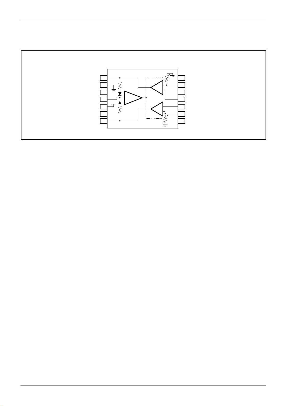
●Block diagram
BA3308F/FV
OUTPUT1
GND
N.C.
ALC
V
CC
N.C.
OUTPUT2
Technical Note
1
2
3
4
5
V
cc
6
7
ALC
14
13
12
11
10
9
8
N.C.
INPUT1
N.C.
NF1
NF2
INPUT2
N.C.
Fig.1
www.rohm.com
3/9
© 2011 ROHM Co., Ltd. All rights reserved.
2012.06 - Rev.C

BA3308F,BA3308FV
●Electrical characteristic curves (Reference data)
Fig.2 Quiescent current vs. Fig.3 Quiescent current vs. Fig.4 Voltage gain vs. frequency
power supply voltage ambient temperature
Fig.5 Total harmonic distortion vs. Fig.6 Voltage gain vs. Fig.7 Closed loop voltage gain vs.
frequency supply voltage ambient temperature
Fig.8 Input conversion noise voltage Fig.9 Channel separation vs. Fig.10 ALC characteristics
vs. signal source resistance frequency
Fig.11 Input/output characteristics Fig.12 Maximum output voltage vs. Fig.13 Maximum output voltage vs.
power supply voltage load resistance
Technical Note
www.rohm.com
4/9
© 2011 ROHM Co., Ltd. All rights reserved.
2012.06 - Rev.C

BA3308F,BA3308FV
●Description of operations
1. Recording
1) Record amplifier
The BA3308F/FV amplifier of ch1 and ch2 input stage
(13pin, 9pin) can be direct coupled or use coupling
capacitors (C1/C2). The voltage gain of the record amplifier
is determined by G
control of the pop noise that occurs at power-on (see
“Cautions on use”) and direct current bias fed back is set by
R5/R6 and C5/C6 at the output stage.
V=R5/R3. The R5/R6, and C3/R3 regulate
Technical Note
BA3308
2 (8) 1 (9) 3 (7) 5
13(9)
R
(R2)
3.9k
C
(C2)
10F
11(10) 1 (7)
1
R
3
1
INPUT
(R4)
39
C
3
(C4)
100F
ch1
(ch2)
R
5
(R6)
18k
Fig.14
Fig.5
Cont
C
(C6)
10F
5
OUTPUT
C
(C8)
22F
ch2
(ch1)
ch2
(ch1)
4
7
R
(R8)
1M
7
2) ALC
The BA3308F/FV has an on-chip signal rectifier and electronic
volume needed for ALC. The signal rectifier compares the direct
current output voltage that is superposed in the output stage (1, 7pin)
signal to the reference voltage 4.5V
F (≒3V; 1VF is approximately
0.7V) in the comparator circuit and if the output voltage is higher, it
turns the comparator ON to charge the smoothing capacitor C
Since the operation point of the output stage of amplifier ch1 and ch2
is fixed at 3V
F, the comparator turns ON when the peak value of the
signal output voltage is 1.5VF (effective value approx. 0.75V). Once
the direct current signal for electronic volume is controlled, ALC
operation starts. The electronic volume, which is connected between
the input line (13, 9pin) and GND, causes the input signal to
attenuate according to the ratio of the external resistance (R
the resistance value of the electronic volume. The ALC range varies
according to the values of R
1 and R2. For small ALC variation the
S/N will determinate an adequate ALC range is obtained by applying
several k of the R
1 and R2. The attack time and recovery time of
ALC are set according to C7 and R7 of 4pin. If the time constants
7, R7) are large, the recovery time will be long and as C7 becomes
(C
smaller, and the attack time will be shorter.
7.
1, R2) to
V
3V
OUT
(DCAC)
F
ch1
(ch2)
4.5V
ch2
(ch1)
F
ch2
(ch1)
ContComp
BA3308
1 (7) 4 13(9)
3 (7)
Fig.15
Fig.6
5
C
R
7
7
2 (8)
R
(R2)
1
www.rohm.com
5/9
© 2011 ROHM Co., Ltd. All rights reserved.
2012.06 - Rev.C

BA3308F,BA3308FV
2. On playback
Since amplifier ch1 and ch2 are used as a NAB equalizer
.
amplifier at playback, a time constant circuit is established in
the NF section (1-11pin, 7-10pin) to obtain NAB
characteristics. The voltage gain at this time is determined by
the following formula:
V = │R11+R9/ (│+jC9・R9)│/R3
G
Obtain the necessary gain by regulating the (power-on pop
noise prevention) NAB time constant circuit in the same way
when regulating the gain at recording stage. The operating
point of the output stage (1,7pin) is fixed at 3VF.
Accordingly, even if V
MAX-VCC characteristic (Fig.13), the maximum output voltage
V
does not rise above 1.2V (Typ.). 4pin is grounded at playback
CC is raised to 5V or more, as in the
since ALC is not needed. For better signal-to-noise ratio
characteristics at playback, don’t use R
attached to the input pin (13pin, 9pin).
1 and R2, which are
13(9)
2 (8)
C
1
(C
2
10μF
Technical Note
11(10)
1 (9)
)
INPUT
R
11
(R12)
4.3k
R
3
(R4)
39
C
3
)
(C
4
100μF
A1
Fig.16
Fig.7
BA3308
(R10)
120k
C
9
(C10)
R
9
0.027μF
1 (7)
3 (7)
OUTPUT
5
C
5
)
(C
6
10μF
4
www.rohm.com
6/9
© 2011 ROHM Co., Ltd. All rights reserved.
2012.06 - Rev.C

BA3308F,BA3308FV
●Measurement circuit
VCC
1M
SW5
22F
220
330F
10F
10k
●Application circuit
C5
VCC=7
R7
1M
R8
220
C8
C7
22F
330F
C6
OUTPUT2
10k
10F
1.2k
1.2k
120k
V
OUTPUT1
10F
1
2
3
4
5
6
7
10F
V
OUTPUT1
120k
33k
33k
OUTPUT2
R11 (R12)
4.3k
0.1F
0.1F
R5
18k
R6
18k
1
SW4A
2
ALC
2
1
ALC
R9 (R10)
120k
C9 (C10)
F
0.027
SW4B
Technical Note
100F
39
Fig.17
Fig.17
39
SW2B
100F
SW2A
C3
R3
14
13
12
11
10
9
8
R4
C4
For playback, connect the following NAB time constant circuit between
pins 11 and 1 and pins 10 and 7 in place of R5 and R6.
Fig.18
V
2
V
V
2
V
100F
39
39
100F
22k
1
2.2k
R1
3.9k
R2
3.9k
1
3.9k
3.9k
2
2
SW1B
C5
10F
C2
10F
SW6A
3
30k
SW3A
SW3B
30k
3
SW6B
INPUT1
INPUT2
V
INPUT1
INPUT2
V
1
V
V
1
www.rohm.com
7/9
© 2011 ROHM Co., Ltd. All rights reserved.
2012.06 - Rev.C

BA3308F,BA3308FV
Technical Note
●Notes for use
1) Numbers and data in entries are representative design values and are not guaranteed values of the items.
2) Although ROHM is confident that the example application circuit reflects the best possible recommendations, be sure
to verify circuit characteristics for your particular application. Modification of constants for other externally connected
circuits may cause variations in both static and transient characteristics for external components as well as this Rohm
IC. Allow for sufficient margins when determining circuit constants.
3) Absolute maximum ratings
Use of the IC in excess of absolute maximum ratings, such as the applied voltage or operating temperature range
(Topr), may result in IC damage. Assumptions should not be made regarding the state of the IC (short mode or open
mode) when such damage is suffered. A physical safety measure, such as a fuse, should be implemented when using
the IC at times where the absolute maximum ratings may be exceeded.
4) GND potential
Ensure a minimum GND pin potential in all operating conditions. Make sure that no pins are at a voltage below the
GND at any time, regardless of whether it is a transient signal or not.
5) Thermal design
Perform thermal design, in which there are adequate margins, by taking into account the permissible dissipation (Pd) in
actual states of use.
6) Short circuit between terminals and erroneous mounting
Pay attention to the assembly direction of the ICs. Wrong mounting direction or shorts between terminals, GND, or other
components on the circuits, can damage the IC.
7) Operation in strong magnetic fields
Using the ICs in a strong electromagnetic field can cause operation malfunction.
8) The BA3308F/FV has an on-chip power supply mute circuit that checks for pop noise at power-on. This prevents the
occurrence of pop noise by timing the charge times of the direct current cut capacitors C
3 and C4 of 10pin and 11pin,
and of capacitor C8 for the ripple filter of 5pin.
Accordingly, to obtain an adequate effect, it is recommended that the constants of the application circuit be used in C
4, R3, R4, C8, and R8.
C
3,
www.rohm.com
8/9
© 2011 ROHM Co., Ltd. All rights reserved.
2012.06 - Rev.C

BA3308F,BA3308FV
●Ordering part number
B A 3 3 0 8 F - E 2
Part No. Part No.
SOP14
8.7± 0.2
(MAX 9.05 include BURR)
14
8
6.2± 0.3
4.4± 0.2
1
1.5± 0.1
1.27
0.11
0.4± 0.1
7
0.1
0.3MIN
0.15± 0.1
(Unit : mm)
Package
F: SOP14
FV: SSOP-B14
<Tape and Reel information>
Embossed carrier tapeTape
Quantity
Direction
of feed
2500pcs
E2
The direction is the 1pin of product is at the upper left when you hold
()
reel on the left hand and you pull out the tape on the right hand
Reel
Packaging and forming specification
E2: Embossed tape and reel
1pin
Order quantity needs to be multiple of the minimum quantity.
∗
Technical Note
Direction of feed
SSOP-B14
6.4 ± 0.3
1.15 ± 0.1
0.2
±
4.4
0.10
14
0.65
1
5.0 ± 0.2
8
7
0.22 ± 0.1
<Tape and Reel information>
Embossed carrier tapeTape
Quantity
Direction
0.3Min.
0.15 ± 0.1
0.1
(Unit : mm)
of feed
2500pcs
E2
The direction is the 1pin of product is at the upper left when you hold
()
reel on the left hand and you pull out the tape on the right hand
Direction of feed
Reel
1pin
Order quantity needs to be multiple of the minimum quantity.
∗
www.rohm.com
9/9
© 2011 ROHM Co., Ltd. All rights reserved.
2012.06 - Rev.C

Notes
No copying or reproduction of this document, in part or in whole, is permitted without the
consent of ROHM Co.,Ltd.
The content specied herein is subject to change for improvement without notice.
The content specied herein is for the purpose of introducing ROHM's products (hereinafter
"Products"). If you wish to use any such Product, please be sure to refer to the specications,
which can be obtained from ROHM upon request.
Examples of application circuits, circuit constants and any other information contained herein
illustrate the standard usage and operations of the Products. The peripheral conditions must
be taken into account when designing circuits for mass production.
Great care was taken in ensuring the accuracy of the information specied in this document.
However, should you incur any damage arising from any inaccuracy or misprint of such
information, ROHM shall bear no responsibility for such damage.
The technical information specied herein is intended only to show the typical functions of and
examples of application circuits for the Products. ROHM does not grant you, explicitly or
implicitly, any license to use or exercise intellectual property or other rights held by ROHM and
other parties. ROHM shall bear no responsibility whatsoever for any dispute arising from the
use of such technical information.
The Products specied in this document are intended to be used with general-use electronic
equipment or devices (such as audio visual equipment, ofce-automation equipment, communication devices, electronic appliances and amusement devices).
The Products specied in this document are not designed to be radiation tolerant.
While ROHM always makes efforts to enhance the quality and reliability of its Products, a
Product may fail or malfunction for a variety of reasons.
Please be sure to implement in your equipment using the Products safety measures to guard
against the possibility of physical injury, re or any other damage caused in the event of the
failure of any Product, such as derating, redundancy, re control and fail-safe designs. ROHM
shall bear no responsibility whatsoever for your use of any Product outside of the prescribed
scope or not in accordance with the instruction manual.
The Products are not designed or manufactured to be used with any equipment, device or
system which requires an extremely high level of reliability the failure or malfunction of which
may result in a direct threat to human life or create a risk of human injury (such as a medical
instrument, transportation equipment, aerospace machinery, nuclear-reactor controller, fuelcontroller or other safety device). ROHM shall bear no responsibility in any way for use of any
of the Products for the above special purposes. If a Product is intended to be used for any
such special purpose, please contact a ROHM sales representative before purchasing.
If you intend to export or ship overseas any Product or technology specied herein that may
be controlled under the Foreign Exchange and the Foreign Trade Law, you will be required to
obtain a license or permit under the Law.
Notice
www.rohm.com
© 2012 ROHM Co., Ltd. All rights reserved.
Thank you for your accessing to ROHM product informations.
More detail product informations and catalogs are available, please contact us.
ROHM Customer Support System
http://www.rohm.com/contact/
R1120A
 Loading...