


Satellite Navigation
Digital Standard for
TM
R&S®WinIQSIM2
User Manual
(;ÚéÎ2)
1176916402
User Manual
Version 04

This document describes the software options for satellite navigation: GPS, Galileo, GLONASS, COMPASS/BeiDou
Described are the following software options:
●
R&S®SMBV-K244/-K266/-K294/-K407
1415.8260.02, 1415.8590.02, 1415.8690.02, 1419.2721.xx
●
R&S®SMW-K244/-K266/-K294/-K407
1413.4880.xx, 1413.7015.xx, 1413.7067.xx, 1413.7115.xx
●
R&S®SGT-K244/-K266/-K294/-K407
1419.6104.02, 1419.7000.02, 1419.7400.02, 1419.7452.02
●
R&S®SMU-K244/-K266/-K294/-K407
1408.5818.02, 1408.8630.02, 1408.8617.02, 1408.8775.02
●
R&S®SMJ-K244/-K266/-K294/-K407
1409.0810.02, 1409.3502.02, 1409.3483.02, 1409.3648.02
●
R&S®AMU-K244/-K266/-K294/-K407
1402.7902.02, 1403.0976.02, 1403.0953.02, 1403.1072.02
●
R&S®AFQ-K244/-K266/-K294/-K407
1401.6454.02, 1415.0330.02, 1415.0318.02, 1410.8556.02
●
R&S®CMW-KW620/-KW621/-KW622/-KW623
1203.6008.02, 1207.8305.02, 1207.8357.02, 1208.8280.02
●
R&S®SFU-K244
2115.2266.02
●
R&S®WV-K1144
2114.8302.02
This manual version corresponds to software version 4.20.047.xx and later of the R&S®WinIQSIM2TM.
© 2018 Rohde & Schwarz GmbH & Co. KG
Mühldorfstr. 15, 81671 München, Germany
Phone: +49 89 41 29 - 0
Fax: +49 89 41 29 12 164
Email: info@rohde-schwarz.com
Internet: www.rohde-schwarz.com
Subject to change – Data without tolerance limits is not binding.
R&S® is a registered trademark of Rohde & Schwarz GmbH & Co. KG.
Trade names are trademarks of the owners.
1176.9164.02 | Version 04 | Satellite Navigation
The following abbreviations are used throughout this manual: R&S®WinIQSIM2TM is abbreviated as R&S WinIQSIM2,
R&S®SMBV100A is abbreviated as R&S SMBV, R&S®SMW200A is abbreviated as R&S SMW, R&S®SGT100A is abbreviated as
R&S SGT, R&S®SMU200A is abbreviated as R&S SMU, R&S®SMJ100A is abbreviated as R&S SMJ, R&S®AMU200A is abbreviated
as R&S AMU, R&S®AFQ100A and R&S®AFQ100B are abbreviated as R&S AFQ, R&S®CMW500 is abbreviated as R&S CMW,
R&S®SFU is abbreviated as R&S SFU, R&S®BTC is abbreviated as R&S BTC; the license types 02/03/07/11/13/16/12 are abbrevi-
ated as xx.

ContentsSatellite Navigation
Contents
1 Preface.................................................................................................... 5
1.1 About this Manual......................................................................................................... 5
1.2 Documentation Overview............................................................................................. 6
1.2.1 Getting Started Manual................................................................................................... 6
1.2.2 User Manual and Help.................................................................................................... 6
1.2.3 Service Manual............................................................................................................... 6
1.2.4 Instrument Security Procedures......................................................................................7
1.2.5 Basic Safety Instructions.................................................................................................7
1.2.6 Data Sheets and Brochures............................................................................................ 7
1.2.7 Release Notes and Open Source Acknowledgment (OSA)............................................ 7
1.2.8 Application Notes, Application Cards, White Papers, etc................................................7
2 Welcome to the GNSS Satellite Navigation Standards.......................8
2.1 Accessing the GNSS Dialog.........................................................................................9
2.2 Scope............................................................................................................................. 9
3 About the GNSS Standards.................................................................10
4 GNSS Configuration and Settings......................................................13
4.1 General Settings..........................................................................................................13
4.2 Navigation Data........................................................................................................... 17
4.3 Almanac Configuration Settings............................................................................... 20
4.4 Time Conversion Configuration Settings................................................................. 21
4.5 Satellite Configuration Settings.................................................................................23
4.5.1 General Satellites Settings............................................................................................24
4.5.2 Configuration of the Satellite Constellation................................................................... 25
4.5.3 Individual Satellite Settings........................................................................................... 26
4.6 Navigation Message Configuration........................................................................... 28
4.7 Marker Settings........................................................................................................... 37
5 How to Generate a Signal with the GNSS Option............................. 40
5.1 How to Generate a One-Satellite Static Generic GNSS Signal............................... 40
5.2 How to Play a GNSS Waveform with Rohde & Schwarz Signal Generator............41
6 Remote-Control Commands............................................................... 42
3User Manual 1176.9164.02 ─ 04

ContentsSatellite Navigation
6.1 Programming Examples............................................................................................. 43
6.2 Primary Settings..........................................................................................................43
6.3 Navigation Data........................................................................................................... 48
6.4 Almanac / RINEX Configuration.................................................................................51
6.5 Time Conversion Configuration.................................................................................56
6.6 Satellites Configuration and Satellites Signal Settings...........................................60
6.7 Navigation Message Configuration........................................................................... 66
6.8 Marker Settings........................................................................................................... 86
List of Commands................................................................................89
Index......................................................................................................94
4User Manual 1176.9164.02 ─ 04

1 Preface
1.1 About this Manual
This user manual provides all the information specific to the GNSS options. All general instrument functions and settings common to all applications and operating modes
are described in the main R&S WinIQSIM2 user manual.
The main focus in this manual is on the provided settings and the tasks required to
generate a signal. The following topics are included:
●
Welcome to the GNSS options R&S SMx-K244/-K266/-K294/-K407
Introduction to and getting familiar with the options
●
About the GNSS options
Background information on basic terms and principles in the context of the signal
generation
●
GNSS Configuration and Settings
A concise description of all functions and settings available to configure signal generation with their corresponding remote control command
●
How to Generate a Signal with the GNSS Options
The basic procedure to perform signal generation tasks and step-by-step instructions for more complex tasks or alternative methods
As well as detailed examples to guide you through typical signal generation scenarios and allow you to try out the application immediately
●
Remote Control Commands
Remote commands required to configure and perform signal generation in a
remote environment, sorted by tasks
(Commands required to set up the instrument or to perform common tasks on the
instrument are provided in the main R&S WinIQSIM2 user manual)
Programming examples demonstrate the use of many commands and can usually
be executed directly for test purposes
●
List of remote commands
Alphabetical list of all remote commands described in the manual
●
Index
PrefaceSatellite Navigation
About this Manual
Contents and scope
This description assumes R&S WinIQSIM2 equipped with all availabe options.
Depending on your model and the installed options, some of the functions may not be
available on your instrument.
Notes on screenshots
When describing the functions of the product, we use sample screenshots. These
screenshots are meant to illustrate as much as possible of the provided functions and
possible interdependencies between parameters. The shown values may not represent
realistic usage scenarios.
5User Manual 1176.9164.02 ─ 04

The screenshots usually show a fully equipped product, that is: with all options installed. Thus, some functions shown in the screenshots may not be available in your particular product configuration.
1.2 Documentation Overview
This section provides an overview of the R&S WinIQSIM2 user documentation. Unless
specified otherwise, you find the documents on the R&S WinIQSIM2 product page at:
www.rohde-schwarz.com/manual/winiqsim2
1.2.1 Getting Started Manual
Introduces the R&S WinIQSIM2 and describes how to set up and start working with the
product. Includes basic operations, typical measurement examples, and general information, e.g. safety instructions, etc. A printed version is delivered with the instrument.
PrefaceSatellite Navigation
Documentation Overview
1.2.2 User Manual and Help
Separate manuals for the base unit and the software options are provided for download:
●
Base unit manual
Contains the description of all instrument modes and functions. It also provides an
introduction to remote control, a complete description of the remote control commands with programming examples, and information on maintenance, instrument
interfaces and error messages. Includes the contents of the getting started manual.
●
Software option manual
Contains the description of the specific functions of an option. Basic information on
operating the R&S WinIQSIM2 is not included.
The contents of the user manuals are available as help in the R&S WinIQSIM2. The
help offers quick, context-sensitive access to the complete information for the base unit
and the software options.
All user manuals are also available for download or for immediate display on the Internet.
1.2.3 Service Manual
Describes the performance test for checking the rated specifications, module replacement and repair, firmware update, troubleshooting and fault elimination, and contains
mechanical drawings and spare part lists.
The service manual is available for registered users on the global Rohde & Schwarz
information system (GLORIS, https://gloris.rohde-schwarz.com).
6User Manual 1176.9164.02 ─ 04

1.2.4 Instrument Security Procedures
Deals with security issues when working with the R&S WinIQSIM2 in secure areas. It is
available for download on the Internet.
1.2.5 Basic Safety Instructions
Contains safety instructions, operating conditions and further important information.
The printed document is delivered with the instrument.
1.2.6 Data Sheets and Brochures
The data sheet contains the technical specifications of the R&S WinIQSIM2. It also
lists the options and their order numbers and optional accessories.
The brochure provides an overview of the instrument and deals with the specific characteristics.
PrefaceSatellite Navigation
Documentation Overview
See www.rohde-schwarz.com/brochure-datasheet/winiqsim2
1.2.7 Release Notes and Open Source Acknowledgment (OSA)
The release notes list new features, improvements and known issues of the current
software version, and describe the software installation.
The open source acknowledgment document provides verbatim license texts of the
used open source software.
See www.rohde-schwarz.com/software/winiqsim2
1.2.8 Application Notes, Application Cards, White Papers, etc.
These documents deal with special applications or background information on particular topics.
See www.rohde-schwarz.com/application/winiqsim2.
7User Manual 1176.9164.02 ─ 04

Welcome to the GNSS Satellite Navigation StandardsSatellite Navigation
2 Welcome to the GNSS Satellite Navigation
Standards
The R&S SMx-K244/-K266/-K294/-K407 are firmware applications that add functionality to generate signals in accordance with the GPS, Galileo, GLONASS and COMPASS/BeiDou.
Differences between the GNSS implementation in GNSS Simulator
R&S SMBV100A and R&S WinIQSIM2
The GNSS implementation in the R&S WinIQSIM2 allows you to generate waveform
files that can be loaded to the following Rohde&Schwarz instruments:
●
R&S SMBV100A
●
R&S SMW200A
●
R&S SGT100A
●
R&S SMU200A
●
R&S SMJ100A
●
R&S AMU200A
●
R&S AFQ100A
●
R&S CMW500
●
R&S CMW280
●
R&S CMW270
●
R&S SFU
●
R&S BTC
Depending on the availability of the respective options, e.g. R&S®SMW-K244/-K266/K294/-K407 you can simulate one GPS, Galileo, GLONASS or BeiDou satellite
respectively on the generator.
As a major difference to the real-time solution of the R&S SMBV100A, the satellite signal generated with the R&S WinIQSIM2 is limited to a certain time period. It depends
on the ARB capacity of the signal generator and the user configurable sample rate of
the satellite signal.
This user manual contains a description of the functionality that the application provides, including remote control operation.
All functions not discussed in this manual are the same as in the base software and
are described in the R&S WinIQSIM2 user manual. The latest version is available at
the product page at:
http://www.rohde-schwarz.com/product/WinIQSIM2.html > "Downloads" > "Manuals".
8User Manual 1176.9164.02 ─ 04

Welcome to the GNSS Satellite Navigation StandardsSatellite Navigation
2.1 Accessing the GNSS Dialog
To open the dialog with GNSS settings
► In the block diagram of the R&S WinIQSIM2, select "Baseband > Satellite Naviga-
tion".
A dialog box opens that displays the provided general settings.
The signal generation is not started immediately. To start signal generation with the
default settings, select "State > On".
Notes on screenshots
When describing the functions of the product, we use sample screenshots. These
screenshots are meant to illustrate as much as possible of the provided functions and
possible interdependencies between parameters. The shown values may not represent
realistic usage scenarios.
Scope
The screenshots usually show a fully equipped product, that is: with all options installed. Thus, some functions shown in the screenshots may not be available in your particular product configuration.
2.2 Scope
Tasks (in manual or remote operation) that are also performed in the base unit in the
same way are not described here.
In particular, it includes:
●
Managing settings and data lists, like storing and loading settings, creating and
accessing data lists, or accessing files in a particular directory.
●
Information on marker signals and filter settings, if appropriate.
●
General instrument configuration, such as configuring networks and remote operation
●
Using the common status registers
For a description of such tasks, see the R&S WinIQSIM2 user manual.
9User Manual 1176.9164.02 ─ 04

About the GNSS StandardsSatellite Navigation
3 About the GNSS Standards
The global navigation satellite system (GNSS) employs the radio signals of several
navigation standards, like GPS, Galileo, GLONASS, BeiDou etc. For several years,
GPS used to be the only standard available for civilian navigation through its C/A civilian code. Nowadays, the GNSS signals and systems are undergoing fast development,
some systems are getting modernized and some are completely new. In the foreseeable future, several more GNSS satellites utilizing more and new frequency will be available.
Brief introduction to the GNSS standards
●
GPS
The Global Positioning System (GPS) consists of several satellites circling the
earth in low orbits. The satellites transmit permanently information that can be used
by the receivers to calculate their current position (ephemeris) and about the orbits
of all satellites (almanac). The 3D position of a receiver on the earth can be determined by carrying out delay measurements of at least four signals emitted by different satellites.
Being transmitted on a single carrier frequency, the signals of the individual satellites can be distinguished by means of correlation (Gold) codes. These ranging
codes are used as spreading code for the navigation message which is transmitted
at a rate of 50 baud.
●
Galileo
Galileo is the European global navigation satellite system that provides global positioning service under civilian control. It is planed to be inter-operable with GPS and
GLONASS and other global satellite navigation systems.
The fully deployed Galileo system consists of 30 satellites (27 operational and 3
spares). Three independent CDMA signals, named E5, E6 and E1, are permanently transmitted by all Galileo satellites. The E5 signal is further sub-divided into
two signals denoted E5a and E5b (see Figure 3-1).
●
GLONASS
Glonass is the russian global navigation satellite system. It is expected to be fully
operational before the end of 2011 with 24 Modernized Glonass Satellites touring
the globe. Together with GPS, up to 54 GNSS Satellites are provided, which will
improve the availability and consequently the navigation performance in high urban
areas.
10User Manual 1176.9164.02 ─ 04

About the GNSS StandardsSatellite Navigation
Figure 3-1: GNSS frequency bands
●
COMPASS/BeiDou
The fully deployed BeiDou Navigation Satellite System (BDS) is a Chinese satellite
navigation system. This navigation system is also know as BeiDou-2 and is expected in 2020. The BDS is a global satellite navigation systems that uses a constellation of 35 satellites to cover the globe. This constellation includes 5 geostationary
orbit satellites (GEO) and 30 non-geostationary satellites; 27 in medium earth orbit
(MEO) and 3 in inclined geosynchronous orbit (IGSO).
The BDS uses frequency allocated in the E1, E2, E5B, and E6 bands.
Single-satellite GNSS signal
This section gives an overview of the basic offline options GPS (R&S SMx-K244), Galileo (R&S SMx-K266), GLONASS (R&S SMx-K294) and BeiDou (R&S SMx-K407).
R&S WinIQSIM2 calculates a single satellite GNSS signal, where static satellites with
constant Doppler shifts are provided for simple receiver test, like receiver sensitivity,
acquisition and tracking test, etc. production tests. Selection and configuration of any
localization data, such as receiver location for instance, is not enabled.
A generic workflow is described in Chapter 5, "How to Generate a Signal with the
GNSS Option", on page 40.
Almanacs
The instrument supports the configuration of the almanac files used. One almanac file
per GNSS navigation standard can be selected.
The Galileo and Beidou satellite constellation are not yet fully in orbit. Hence, no almanac files for Galileo and BeiDou are available. In this implementation, predicted Galileo
and Beidou almanac files are provided for test purposes. The almanac files for GPS
and Galileo use the same format.
11User Manual 1176.9164.02 ─ 04

About the GNSS StandardsSatellite Navigation
Current GNSS almanac data can be downloaded via the Internet and stored on the
hard disk of the instrument:
●
US Coast Guard Navigation Center GPS Homepage http://www.navcen.uscg.gov/?
pageName=gpsAlmanacs
The almanac files are named xxx.alm (for YUMA files) or xxx.al3 (for SEM
files),
Where xxx denotes the day of a year
●
http://www.celestrak.com/GPS/almanac/
The naming convention of the almanac file is: almanac.sem/
yuma.weekXXXX.YYYYYY.txt,
Where xxxx denotes the GPS week and yyyyyy the time of almanac (TOA)
●
ftp://ftp.glonass-iac.ru/MCC/ALMANAC/
The file extension of the Glonass almanac file is: xxx.agl
●
Japanese Space Agency homepage http://qz-vision.jaxa.jp/USE/en/almanac
Available are QZSS almanacs or QZSS+GPS almanac data files.
The almanac files are named zzyyyyxxx.alm (for YUMA files) or
zzyyyyxxx.alm.xml (for XML files),
Where zz=q for QZSS almanacs and zz=qg for QZSS+GPS almanacs;
yyyy denotes the year and xxx denotes the day of a year.
For detailed information on the content and frame structure of navigation data, refer to
the specifications.
12User Manual 1176.9164.02 ─ 04

GNSS Configuration and SettingsSatellite Navigation
4 GNSS Configuration and Settings
Access:
1. Select "Baseband > Satellite Navigation".
2. Select the desired satellite standard, e.g. GPS.
To simplify the description, the selected satellite standard is referred as an "entry
standard".
Note: Most of the parameters provided for configuration are similar and do not
depend on the entry standard. This description uses the GPS standard as a reference.
Satellite standard dependent settings are described separately or the differences
are explicitly stated.
The provided settings enable you to perform general configurations, like to set the
default settings or access further dialogs.
General Settings
The screenshots provided in this description show parameter values that have been
selected to illustrate as much as possible of the provided functions and possible interdependencies between them.
These values are not necessarily representative of realistic test situations.
The remote commands required to define these settings are described in Chapter 6,
"Remote-Control Commands", on page 42.
Settings:
● General Settings..................................................................................................... 13
● Navigation Data.......................................................................................................17
● Almanac Configuration Settings..............................................................................20
● Time Conversion Configuration Settings.................................................................21
● Satellite Configuration Settings...............................................................................23
● Navigation Message Configuration......................................................................... 28
● Marker Settings.......................................................................................................37
4.1 General Settings
Access:
1. Select "Baseband > Satellite Navigation".
2. Select the desired satellite standard, e.g. GPS.
3. Select "General".
13User Manual 1176.9164.02 ─ 04
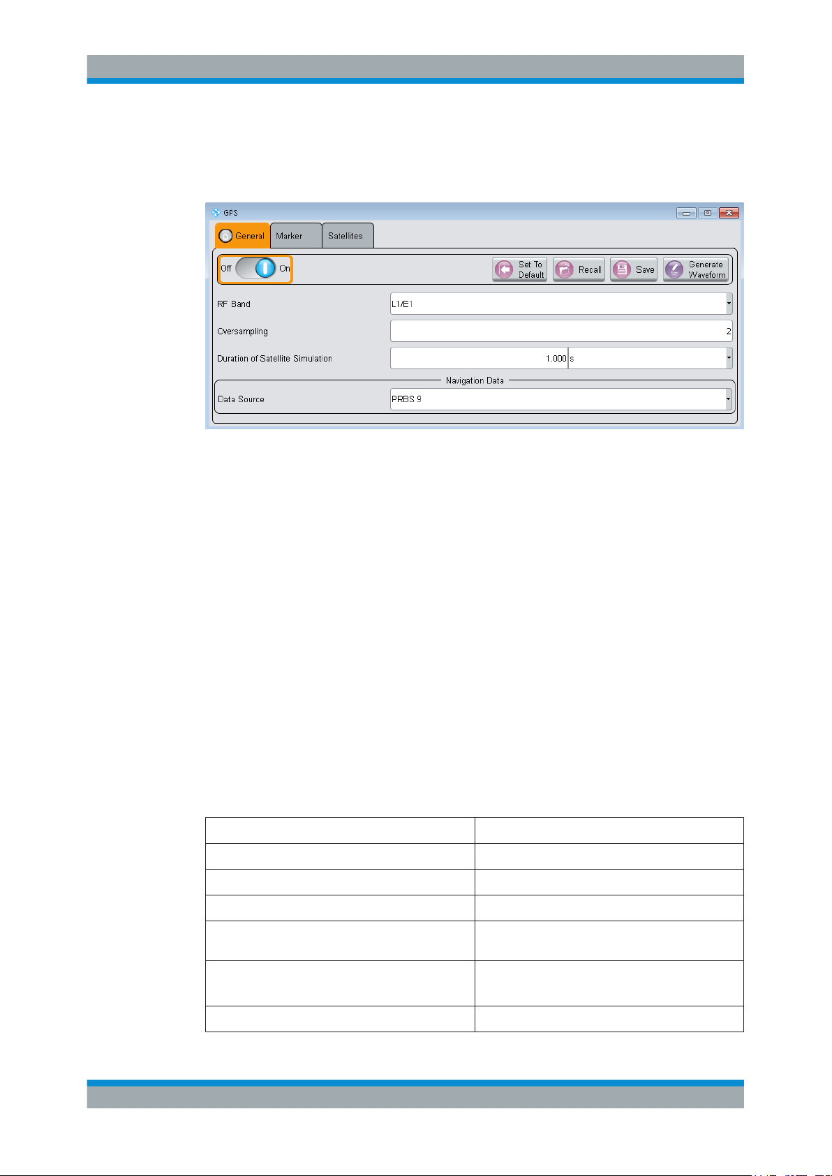
GNSS Configuration and SettingsSatellite Navigation
General Settings
This tab provides access to the default and the "Save/Recall" settings, as well as the
settings of the simulated satellite. Depending on the selected data source, the parameters vary.
Settings:
State..............................................................................................................................14
Set to default................................................................................................................. 14
Save/Recall................................................................................................................... 15
Generate Waveform File............................................................................................... 15
RF Band........................................................................................................................ 15
Simulation Mode........................................................................................................... 16
Oversampling................................................................................................................ 16
Duration Of Satellite Simulation.................................................................................... 16
State
Activates the standard and deactivates all the other digital standards and digital modulation modes in the same path.
Remote command:
<subsystem>:STATe on page 45
Set to default
Calls the default settings. The values of the main parameters are listed in the following
table.
Parameter Value
State Not affected by "Set to default"
RF Band L1/E1
Simulation Mode Static
Almanac GPS_SEM678.txt/GAL_Yuma678.txt/GLO_678.agl/
Oversampling
Duration of Satellite Simulation
Data Source PRBS9
Beidou_Yuma678.txt
2
1s
14User Manual 1176.9164.02 ─ 04

GNSS Configuration and SettingsSatellite Navigation
Parameter Value
System Time Time basis of the entry standard
General Settings
Satellite configuration
Maximum Number of Satellites 1
State satellite 1 On
Standard GPS, Galileo, GLONASS or BeiDou (depending on
Signal C/A, E1-DEF, R-C/A or B1-C/A (depending on the
the entry standard)
entry standard)
Remote command:
<subsystem>:PRESet on page 44
Save/Recall
Accesses the "Save/Recall" dialog, that is the standard instrument function for saving
and recalling the complete dialog-related settings in a file. The provided navigation
possibilities in the dialog are self-explanatory.
The filename and the directory, in which the settings are stored, are user-definable; the
file extension is however predefined.
The following file extensions are used: *.gps, *.galileo, *.glonass respectively.
Remote command:
[:SOURce<hw>]:BB:GPS:SETTing:CATalog? on page 45
[:SOURce<hw>]:BB:GALileo:SETTing:CATalog? on page 45
<subsystem>:SETTing:STORe on page 46
<subsystem>:SETTing:LOAD on page 46
<subsystem>:SETTing:DELete on page 46
Generate Waveform File
With enabled signal generation, triggers the instrument to store the current settings as
an ARB signal in a waveform file. Waveform files can be further processed by the ARB
and/or as a multi-carrier or a multi-segment signal.
The filename and the directory it is stored in are user-definable; the predefined file
extension for waveform files is *.wv.
See also:
●
Chapter 5.1, "How to Generate a One-Satellite Static Generic GNSS Signal",
on page 40
●
Chapter 5.2, "How to Play a GNSS Waveform with Rohde & Schwarz Signal Generator", on page 41 .
Remote command:
<subsystem>:WAVeform:CREate on page 47
RF Band
Determines the RF band, i.e. the upper or lower RNSS band.
15User Manual 1176.9164.02 ─ 04

GNSS Configuration and SettingsSatellite Navigation
Carrier
F
Shift Doppler
1
Simulation Satellite of Duration
Simulation of Duration
General Settings
The different satellites are modulated on their corresponding standard carrier frequencies.
See Table 4-1).
Table 4-1: Carrier frequencies
Navigation Standard "RF Band" Carrier Frequency, GHz Required SW Option
GPS L1
L2
GALILEO E1 1.57542 R&S SMx-K266
GLONASS L1
L2
BeiDou L1 1.561098 R&S SMx-K407
1.57542
1.2276
1.602
1.246
R&S SMx-K244
R&S SMx-K294
Remote command:
<subsystem>:RFBand on page 45
Simulation Mode
Indicates Sets the simulation mode.
"Static"
Enables you to configure the satellite signal.
Remote command:
<subsystem>:SMODe on page 45
Oversampling
Determines the upsampling factor.
A higher upsampling factor improves the filtering but increases the waveform size proportionally and hence limits the maximum Duration Of Satellite Simulation.
Remote command:
<subsystem>:FILTer:OSAMpling on page 47
Duration Of Satellite Simulation
Determines the duration of the satellite simulation.
The resulting duration of the simulation is calculated as follows:
Where F
is the frequency selected with the parameter RF Band.
Carrier
The maximum duration of satellite simulation depends on the Oversampling and the
ARB memory size of the connected instrument.
Remote command:
<subsystem>:DURation on page 46
16User Manual 1176.9164.02 ─ 04

4.2 Navigation Data
Access:
► Select "GNSS Main Dialog > Navigation Data"
With the provided settings, you can define the data source for navigation information.
Data Source.................................................................................................................. 17
Time Conversion Configuration.....................................................................................18
Simulation Start Time....................................................................................................18
Almanac Configuration..................................................................................................19
GNSS Configuration and SettingsSatellite Navigation
Navigation Data
Data Source
Selects data source for the navigation information.
Navigation data is essential for calculating the positions of the satellites. It also contains the information about the currently valid space vehicle IDs.
"Real Navigation Data"
You can download Almanac files ("Real Navigation Data") from the
Internet and store them on the hard disk of your instrument. If necessary, reconfigure manually these downloaded files.
If you work in "User Localization" mode, you can also use RINEX
files.
Almanac files for Galileo and BeiDou are not available for download.
To simulate the movement of Galileo and BeiDou satellites on their
designed orbits, you find predicted almanacs provided with this software.
Use the Almanac Configuration parameter to select the almanac file
per navigation standard.
17User Manual 1176.9164.02 ─ 04

"PRBSxx/Data List/Pattern"
Arbitrary data is available in "Static" mode.
A GNSS receiver recognizes signals generated in this way. There is
no real navigation data modulated with the GNSS spreading code but
the signal is sufficient for simple functional tests and sensitivity tests.
The receiver measures and displays the carrier to noise ratio of the
signal.
The following standard data sources are available:
●
"All 0, All 1"
An internally generated sequence containing 0 data or 1 data.
●
"PNxx"
An internally generated pseudo-random noise sequence.
●
"Pattern"
An internally generated sequence according to a bit pattern.
Use the "Pattern" box to define the bit pattern.
●
"Data List/Select DList"
A binary data from a data list, internally or externally generated.
Select "Select DList" to access the standard "Select List" dialog.
– Select the "Select Data List > navigate to the list file *.dm_iqd
> Select" to select an existing data list.
– Use the "New" and "Edit" functions to create internally new
data list or to edit an existing one.
– Use the standard "File Manager" function to transfer external
data lists to the instrument.
See also section "Custom Digital Modulation > Data Source" in
the R&S WinIQSIM2 user manual.
GNSS Configuration and SettingsSatellite Navigation
Navigation Data
"Zero Navigation Data"
Navigation data with the ephemeris, almanac and satellite clock correction parameters set to zero.
Synchronization, timing and structure (e.g. channel coding) of the
message are the same as for "Real Navigation Data".
In this mode, you can select from the full set of SV-IDs for all GNSS.
In the "Real Navigation Data" mode, available are only the almanac
records that are existing in the almanac file and the healthy satellites.
Remote command:
<subsystem>:NAVigation:DATA on page 48
<subsystem>:NAVigation:DATA:DSELect on page 49
<subsystem>:NAVigation:DATA:PATTern on page 49
Time Conversion Configuration
Opens the Time Conversion Configuration Settings dialog.
Simulation Start Time
Sets the simulation start time in the format of the selected "Time Basis".
18User Manual 1176.9164.02 ─ 04

GNSS Configuration and SettingsSatellite Navigation
Navigation Data
"Time Basis"
Remote command:
<subsystem>:NAVigation:SIMulation:TBASis on page 49
"Date [dd.mm.yyyy], Time [hh:mm:ss:xxx]"
Remote command:
<subsystem>:NAVigation:SIMulation:DATE on page 49
<subsystem>:NAVigation:SIMulation:TIME on page 50
"Week Number, Time of Week (TOW)"
Remote command:
<subsystem>:NAVigation:SIMulation:WNUMber on page 50
<subsystem>:NAVigation:SIMulation:TOWeek on page 50
Per default, the timebase of the entry standard is used. If different
timebase is selected, the time is automatically recalculated and displayed in the selected time format.
Note: Use the Time Conversion Configuration Settings dialog to con-
figure the parameters, necessary for time conversion between the
proprietary time of the navigation standard and the UTC.
(enabled for "Data Source > Real Navigation Data" and "Time Basis >
UTC/GLO")
Enters the date for the simulation in DD.MM.YYYY format of the Gregorian calendar and the exact simulation start time in UTC time format. The simulation time is not limited to the almanac week.
(enabled for "Time Basis > GPS/GST/BDT/QZSST" and "Data Source
> Real Navigation Data")
The satellite clocks in the GPS and Galileo navigation systems are
not synchronized to the UTC. They use a proprietary time, the GPS
and the Galileo system time. The format used for these systems is
week number (WN) and Time of Week (TOW), that is the simulation
start time within this week.
The Time of Week (TOW) is expressed in number of seconds and
covers an entire week. The value is reset to zero at the end of each
week.
The weeks are numbered starting from a reference time point
(WN_REF=0), that depends on the navigation standard:
●
GPS reference point: January 6, 1980 (00:00:00 UTC)
●
GALILEO reference point: August 22, 1999
●
BeiDou reference point: January 01, 2006
The default value of this parameter is equal to the Week of the almanac that corresponds to the navigation standard used as an entry
standard.
Almanac Configuration
Accesses the Almanac Configuration settings.
You can select one almanac file per navigation standard.
19User Manual 1176.9164.02 ─ 04

4.3 Almanac Configuration Settings
To access this dialog:
1. Select "GNSS > General > Navigation Data"
2. Select "Data Source > Real Naviagtion Data"
3. Select "Almanac"
In this dialog, you select the almanac files.
GNSS Configuration and SettingsSatellite Navigation
Almanac Configuration Settings
Almanac Configuration
Displays the settings of the selected almanac files per navigation standard.
One almanac file can be selected per navigation standard. Predefined or user-defined
almanac files can be loaded.
When an almanac file is selected, the time information of the file (Week, SEM and
TOA) is indicated in the table. The SEM and TOA are indicated in Greenwich Mean
Time.
Parameter SCPI command
"Almanac File" <subsystem>:NAVigation:ALManac:<GNSS>:FILE on page 52
<subsystem>:SVID:<GNSS>:LIST on page 55
"Time of Applicability
1)
(TOA)"
"Data Span" <subsystem>:NAVigation:ALManac:<GNSS>:SPAN? on page 52
"Week Number"
"Week Span"
2)
2)
<subsystem>:NAVigation:ALManac:<GNSS>:TOAPplicability:
TOWeek on page 55
<subsystem>:NAVigation:ALManac:<GNSS>:TOAPplicability:
WNUMber on page 55
<subsystem>:NAVigation:ALManac:GLONass:TOAPplicability:
DATE? on page 53
<subsystem>:NAVigation:ALManac:GLONass:TOAPplicability:
TIME? on page 54
<subsystem>:NAVigation:ALManac:<GNSS>:WNUMber on page 55
<subsystem>:NAVigation:ALManac:<GNSS>:DATE:BEGIn on page 53
<subsystem>:NAVigation:ALManac:<GNSS>:DATE:END on page 53
1)
●
TOA format for GPS: (WN, TOW) WN_REF (6 Jan 1980 00:00:00 UTC)
TOA format for Galileo: (WN, TOW) WN_REF (22 August 1999 00:00:00 UTC)
2)
●
"Week Number" and "Week Span": no SCPI command for Glonass
20User Manual 1176.9164.02 ─ 04

GNSS Configuration and SettingsSatellite Navigation
Time Conversion Configuration Settings
For an overview of the supported almanac files, see "Almanacs" on page 11.
4.4 Time Conversion Configuration Settings
Access:
1. Select "Baseband > Satellite Navigation".
Select the satellite standard, for example "GPS".
2. Select "Navigation Data > Data Source > Real Navigation Data".
3. Select "Navigation Data > Time Conversion Config...".
This dialog contains the settings required to configure the time conversion from a
navigation standard, for example GPS to UTC. The conversion settings are necessary for switching from one time basis to another.
The time conversion is performed according to the following formula:
t
= (tE - delta_t
UTC
delta_t
UTC
tE = t
GPS
= delta_tLS+A0+A1 (tE-Tot+604800(WN-WNot)) and
or t
Galileo
) modulo 86400, where delta_t
UTC
and tE are as follows:
UTC
21User Manual 1176.9164.02 ─ 04

Time Conversion Configuration Settings
The GNSS implementation in the R&S WinIQSIM2 is a simplified offline version of the
real-time one and provides the capability to generate a one-satellite generic signal.
Therefore the time conversion parameters table is adjusted accordingly to one satellite
in R&S WinIQSIM2. You find the differences explicitly stated in the description.
Time Conversion Parameters........................................................................................22
Leap Second Configuration...........................................................................................22
UTC-UTC(SU)...............................................................................................................22
Time Conversion Parameters
The basis for the time conversion is the UTC. The parameters of each of the navigation
standards are set as an offset to the UTC.
For better readability, the values of the time correction parameters are input as integer
in the same way as they are included in the satellite's navigation message. The corresponding "Scale Factor" and the "Scaled Value" are also displayed.
Parameter Description SCPI Command
GNSS Configuration and SettingsSatellite Navigation
"A_0" Constant term of polynomial, A
"A_1"
"t_ot" UTC data reference Time of Week, t
"WN_t" UTC data reference Week Number, WN
1st order term of polynomial, A
0
1
ot
<subsystem>:NAVigation:TCONversion:GPS:AZERo
on page 57
<subsystem>:NAVigation:TCONversion:GPS:AONE
on page 57
<subsystem>:NAVigation:TCONversion:GPS:TOT
on page 58
<subsystem>:NAVigation:TCONversion:GPS:WNOT
t
on page 58
Leap Second Configuration
The GPS time does not consider time corrections that are typical for the UTC, such as
the leap second for instance.
The date of the next expected correction is determined by the parameter "Next Leap
Second Date".
As of June 30, 2012, the value of the "Current Leap Second", is 16 seconds.
Parameter Description SCPI Command
"Synchronize" Synchronizes the leap second
according to the simulation time.
"Current Leap Seconds (Ref.
1980)"
Displays the currently used leap
second.
<subsystem>:NAVigation:TCONversion:LEAP:SYNC
on page 59
<subsystem>:NAVigation:TCONversion:LEAP:
SEConds on page 59
UTC-UTC(SU)
(for GLONASS satellites)
The Universal Time Coordinate (UTC) as used for GPS and Galileo can have a phase
shift and a frequency drift compared to the Russian UTC basis (UTC(SU)). These settings are provided for configuration of the UTC differences UTC - UTC(SU) as transmitted by GLONASS satellites.
22User Manual 1176.9164.02 ─ 04

Parameter Description SCPI Command
GNSS Configuration and SettingsSatellite Navigation
Satellite Configuration Settings
"UTC(SU) Reference Date"
"A_0" Constant term of polynomial A0 (virtual) <subsystem>:NAVigation:TCONversion:UTCSu:
"A_1"
Indicates the UTC-UTC (SU) time conversion
reference date.
1st order term of polynomial, A1 (virtual)
<subsystem>:NAVigation:TCONversion:UTCSu:
DATE? on page 59
AZERo on page 58
<subsystem>:NAVigation:TCONversion:UTCSu:AONE
on page 58
The Glonass satellites transmit the offset between GPS and GLONASS system time as
part of their navigation message. They assume only a delay and no frequency drift.
The time offset is calculated as following:
GPS – GLONASS = "GPS – UTC" + "UTC – UTC(SU)" – "GLONASS (UTC(SU) + 3h)" – 3h
For hybrid GNSS configuration with activated GLONASS satellites, this GPS – GLONASS time offset is maintained constant. This is done by automatically adjusting the
"GPS-UTC" drift parameters ("A_1","T_ot" and "WN_ot") while changing the "UTC –
UTC(SU)" parameters.
4.5 Satellite Configuration Settings
Access:
1. Select "Baseband > Satellite Navigation".
Select the desired satellite standard, for example GPS.
23User Manual 1176.9164.02 ─ 04

2. Select "Satellite Configuration".
GNSS Configuration and SettingsSatellite Navigation
Satellite Configuration Settings
The GNSS implementation in R&S WinIQSIM2 is a simplified offline version of the
realtime option. In the offline version, you can generate a one-satellite generic signal; that is, only one satellite can be activated and configured. You find the differences between the real-time and the offline versions explicitly stated in the description.
4.5.1 General Satellites Settings
Use Spreading.............................................................................................................. 24
Galileo Sat. Modulation................................................................................................. 24
Use Spreading
Activates/deactivates spreading.
Remote command:
<subsystem>:SPReading[:STATe] on page 61
Galileo Sat. Modulation
Selects the modulation mode used for modulating the Galileo carrier signal.
Tip: Select BOC(1,1) modulation to reduce the sample rate required to simulate a certain period of time.
Remote command:
<subsystem>:GALModulation on page 61
24User Manual 1176.9164.02 ─ 04

GNSS Configuration and SettingsSatellite Navigation
4.5.2 Configuration of the Satellite Constellation
Maximum Number of Satellites..................................................................................... 25
Satellite State................................................................................................................ 25
Standard........................................................................................................................25
Signals.......................................................................................................................... 25
SV-ID/PRN.................................................................................................................... 25
Maximum Number of Satellites
The GNSS implementation in the R&S WinIQSIM2 provides one satellite signal.
Remote command:
<subsystem>:SATellite:COUNt on page 61
Satellite State
Activates/deactivates the satellite.
Remote command:
<subsystem>:SATellite<st>:STATe on page 65
Satellite Configuration Settings
Standard
Indicates the navigation standard to that the satellite belongs.
Remote command:
<subsystem>:SATellite<st>:STANdard on page 65
Signals
Indicates the type of signal the satellite is using.
Table 4-2: Overview of the supported signals
Band Entry Point Standard Signal Minimum Required Option
L1/E1 GPS GPS C/A R&S SMx-K244
Galileo Galileo E1-DEF R&S SMx-K266
GLONASS GLONASS R-C/A R&S SMx-K294
BeiDou BeiDou B1-C/A R&S SMx-K407
Remote command:
<subsystem>:SATellite<st>:SIGNal on page 64
SV-ID/PRN
Enters the Space Vehicle ID (SV-ID) or Pseudo-Random Noise (PRN) of the satellite to
be simulated. This value is used to generate the corresponding spreading code.
Note: The SV IDs of the GLONASS satellites are with 64 smaller than their PRN number, e.g to GLONASS satellite R5 corresponds PRN=69.
If "Real Navigation Data" is used, you can select healthy satellites from the almanac
records; otherwise, any ID can be selected.
SV ID set to "N.A." indicates a not assigned satellite.
Remote command:
<subsystem>:SATellite<st>:SVID on page 65
25User Manual 1176.9164.02 ─ 04

4.5.3 Individual Satellite Settings
Comprises the settings of the selected satellite.
Standard Chip Rate.......................................................................................................26
Frequency Number....................................................................................................... 26
Orbit Type......................................................................................................................26
Modulation.....................................................................................................................26
Navigation..................................................................................................................... 27
Initial Code Phase......................................................................................................... 27
Pseudorange.................................................................................................................27
Time Shift/ chips............................................................................................................27
Doppler Shift................................................................................................................. 27
Initial Carrier Phase ......................................................................................................27
Resulting Start Frequency.............................................................................................28
Resulting Start Chip Rate..............................................................................................28
Standard Chip Rate
Displays the chip rate.
Remote command:
<subsystem>:SATellite<st>:SCRate? on page 64
GNSS Configuration and SettingsSatellite Navigation
Satellite Configuration Settings
Frequency Number
(enabled for GLONASS satellites)
Frequency number indicates the subcarrier used to modulate the GLONASS satellite.
If you use "Data Source > Real Navigation Data", the frequency number is retrieved
from the selected almanac file. If you use arbitrary data, the frequency number is configurable.
Remote command:
<subsystem>:SATellite<st>:FNUMber on page 62
Orbit Type
(enabled for BeiDou satellites)
Indicates the orbit type the BeiDou satellite is using. The BeiDou global satellite navigation system uses a constellation of 35 satellites with following orbits:
"GEO"
"MEO"
"IGSO"
Remote command:
<subsystem>:SATellite<st>:ORBit? on page 63
Modulation
Displays the modulation used for modulating the carrier signal.
Remote command:
<subsystem>:SATellite<st>:MODulation? on page 63
Five geostationary orbit satellites with "SV-ID = 1 to 5"
27 middle earth orbits global satellites
3 Inclined Geosynchronous Satellite Orbit regional satellites, visible
only in China and Australia
26User Manual 1176.9164.02 ─ 04

GNSS Configuration and SettingsSatellite Navigation
Satellite Configuration Settings
Navigation...
Accesses the dialog for configuring the parameters of the navigation message.
See Chapter 4.6, "Navigation Message Configuration", on page 28
Initial Code Phase
(enabled only in "Static" mode and for arbitrary navigation data source)
Sets the initial code phase.
In R&S WinIQSIM2, the actual simulated resolution for initial code phase depends on
the sample rate. The selected Initial Carrier Phase is internally rounded to a sample. To
increase the sample rate, use the Oversampling function.
Remote command:
<subsystem>:SATellite<st>:CPHase on page 63
Pseudorange
In R&S WinIQSIM2, it is fixed to 0.
Displays the propagation delay from satellite to receiver in meters that is calculated as
follows:
Pseudorange = Time Shift * c / Standard Chip Rate, where c is the
speed of light.
Remote command:
<subsystem>:SATellite<st>:PRANge on page 64
Time Shift/ chips
Displays the propagation delay from satellite to receiver. The time shift is displayed in
chips.
In R&S WinIQSIM2, it is fixed to 0.
Remote command:
<subsystem>:SATellite<st>:TSHift on page 65
Doppler Shift
Sets the Doppler shift for a constant signal profile of the simulated signal of the satellite. The simulation of Doppler shifted signals can be used to check the receiver characteristics under more realistic conditions than with zero Doppler.
The instrument calculates also the variations in the chip rate of the code. Current values of the Doppler shifted carrier frequency and chip rate are displayed as:
●
Resulting Start Frequency
●
Resulting Start Chip Rate
Remote command:
<subsystem>:SATellite<st>:DSHift on page 62
Initial Carrier Phase
Displays the initial carrier phase.
In R&S WinIQSIM2, it is fixed to 0.
Remote command:
<subsystem>:SATellite<st>:ICPHase on page 63
27User Manual 1176.9164.02 ─ 04

GNSS Configuration and SettingsSatellite Navigation
Navigation Message Configuration
Resulting Start Frequency
Indicates the currently valid values for Doppler shifted carrier frequency.
The resulting frequency is calculated according to the following:
●
GPS, Galileo, BeiDou
f
= f
●
resulting
Where f
Glonass
f
band_L1
+ f
band
is set with parameter RF Band.
band
= 1602 MHz, f
Doppler
,
band_L2
= 1247 MHz
k = frequency number
f
Glo_L1_resulting
f
Glo_L2_resulting
, MHz = 1602 + ( k * 0.5625) + f
, MHz = 1247 + ( k * 0.4375) + f
Doppler
Doppler
Remote command:
<subsystem>:SATellite<st>:FREQuency? on page 62
Resulting Start Chip Rate
Indicates the currently valid values for the chip rate. The relevant change to the chip
rate is carried out automatically if the Doppler shift is changed.
The resulting chip rate is calculated according to the following:
●
GPS, Galileo, BeiDou
f
= f
resulting
Where f
f
code_GPS/Galileo
●
Glonass on L1/E1 band
f
resulting
●
Glonass on L2 band
f
resulting
* {1 + f
code
is set with parameter RF Band,
band
=
= f
* {1 + f
code
= f
* {1 + f
code
1.023 MHz and f
Doppler
Doppler
Doppler
/ f
},
band
code_BeiDou
/ [f
+ k * 562500 (Hz)]}
band
/[ f
+ k * 437500 (Hz)]}
band
=
2.046 MHz
Remote command:
<subsystem>:SATellite<st>:CACRate? on page 61
4.6 Navigation Message Configuration
To access these settings:
1. Select "Baseband > Satellite Navigation". Select the satellite standard, for example
"GPS".
2. Select "Satellite Configuration > Navigation...".
The parameters of the navigation message of each satellite are read only.
The input parameters are integer values, so that you set them in the same way as
they are included in the satellite's navigation message. The scaled values and the
scaling factors are also displayed. Different scaling factors apply for the same
parameters in the different GNSS standards.
28User Manual 1176.9164.02 ─ 04

GNSS Configuration and SettingsSatellite Navigation
Navigation Message Configuration
29User Manual 1176.9164.02 ─ 04
 Loading...