

Page 1

®
R&S
VTS
Compact Video Tester
Getting Started
(E@<R2)
2116123402
Version 08
Getting Started
Page 2

This manual describes the R&S®VTS (2115.7100.02).
The software contained in this product uses several valuable open source software packages. For information, see the "Open Source Acknowledgment" document, which is available for download from the
R&S VTS product page at www.rohde-schwarz.com/product/vts.html > "Downloads" > "Firmware".
Rohde & Schwarz would like to thank the open source community for their valuable contribution to embedded computing.
© 2020 Rohde & Schwarz GmbH & Co. KG
Mühldorfstr. 15, 81671 München, Germany
Phone: +49 89 41 29 - 0
Email: [email protected]
Internet: www.rohde-schwarz.com
Subject to change – Data without tolerance limits is not binding.
R&S® is a registered trademark of Rohde & Schwarz GmbH & Co. KG.
Trade names are trademarks of the owners.
2116.1234.02 | Version 08 | R&S®VTS
Throughout this manual, products from Rohde & Schwarz are indicated without the ® symbol , e.g.
R&S®VTS is indicated as R&S VTS.
Page 3

R&S®VTS
Contents
1 Safety and Regulatory Information...................................... 7
1.1 Safety Instructions................................................................................7
1.2 Labels on the Product........................................................................ 10
1.3 Warning Messages in the Documentation........................................11
1.4 Korea Certification Class B................................................................11
2 Documentation Overview....................................................13
2.1 Getting Started Manual.......................................................................13
2.2 User Manuals and Help...................................................................... 13
Contents
2.3 Tutorials............................................................................................... 13
2.4 Printed Safety Instructions................................................................ 14
2.5 Data Sheets and Brochures............................................................... 14
2.6 Release Notes and Open Source Acknowledgment (OSA).............14
2.7 Application Notes, Application Cards, White Papers, etc...............14
3 Key Features........................................................................ 15
4 Preparing for Use.................................................................17
4.1 Lifting and Carrying............................................................................17
4.2 Unpacking and Checking................................................................... 17
4.3 Choosing the Operating Site............................................................. 18
4.3.1 Setting Up the Product..........................................................................18
4.4 Considerations for Test Setup...........................................................20
4.5 Connecting to Power.......................................................................... 21
4.6 Connecting External USB Devices....................................................21
4.6.1 Memory Stick........................................................................................ 22
4.6.2 External Drive....................................................................................... 22
3Getting Started 2116.1234.02 ─ 08
Page 4

R&S®VTS
4.7 Switching On or Off............................................................................ 22
4.8 Checking the Provided Options........................................................ 23
4.9 Turn-On Tests......................................................................................24
Contents
5 Instrument Tour................................................................... 25
5.1 Front Panel.......................................................................................... 25
5.1.1 Status LEDs.......................................................................................... 26
5.1.2 Headphones..........................................................................................26
5.1.3 10 MHz REF IN.....................................................................................26
5.2 Rear Panel........................................................................................... 27
5.2.1 AC Power Supply Connector and Switch..............................................27
5.2.2 DVI Port................................................................................................ 28
5.2.3 1000 BASE-T........................................................................................ 28
5.2.4 USB Interfaces......................................................................................28
5.2.5 HDMI Connector................................................................................... 29
6 Operating the R&S VTS in a LAN....................................... 31
6.1 Connecting the R&S VTS to a Network.............................................31
6.2 Connecting the R&S VTS to a Computer..........................................32
6.2.1 Windows 7 Operating System...............................................................32
6.2.2 Other Operating Systems..................................................................... 33
6.3 Zero Configuration Networking......................................................... 33
6.4 Configuring the Network Card...........................................................33
6.5 Firewall Settings................................................................................. 35
7 Installed Software................................................................ 37
7.1 Operating System............................................................................... 37
7.1.1 Login..................................................................................................... 37
7.1.2 Windows 7 Start Menu..........................................................................38
4Getting Started 2116.1234.02 ─ 08
Page 5

R&S®VTS
7.2 Additional Software............................................................................ 38
7.3 Backup and Restore Application.......................................................38
7.3.1 Creating a Backup................................................................................ 40
7.3.2 Restoring a Selected Backup Version...................................................41
7.3.3 Deleting a Backup.................................................................................42
Contents
8 Contacting Customer Support........................................... 43
Index..................................................................................... 45
5Getting Started 2116.1234.02 ─ 08
Page 6

R&S®VTS
Contents
6Getting Started 2116.1234.02 ─ 08
Page 7

R&S®VTS
Safety and Regulatory Information
Safety Instructions
1 Safety and Regulatory Information
The product documentation helps you use the product safely and efficiently. Follow the instructions provided here and in the Chapter 1.1, "Safety Instructions",
on page 7.
Intended use
The product is intended for the development, production and verification of electronic components and devices in industrial, administrative, and laboratory environments. Use the product only for its designated purpose. Observe the operating
conditions and performance limits stated in the data sheet.
Where do I find safety information?
Safety information is part of the product documentation. It warns you of potential
dangers and gives instructions on how to prevent personal injury or damage
caused by dangerous situations. Safety information is provided as follows:
●
In Chapter 1.1, "Safety Instructions", on page 7. The same information is
provided in many languages as printed "Safety Instructions". The printed
"Safety Instructions" are delivered with the product.
●
Throughout the documentation, safety instructions are provided when you
need to take care during setup or operation.
1.1 Safety Instructions
Products from the Rohde & Schwarz group of companies are manufactured
according to the highest technical standards. To use the products safely, follow
the instructions provided here and in the product documentation. Keep the product documentation nearby and offer it to other users.
Use the product only for its intended use and within its performance limits. Intended use and limits are described in the product documentation such as the data
sheet, manuals and the printed safety instructions. If you are unsure about the
appropriate use, contact Rohde & Schwarz customer service.
Using the product requires specialists or specially trained personnel. These users
also need sound knowledge of at least one of the languages in which the user
interfaces and the product documentation are available.
7Getting Started 2116.1234.02 ─ 08
Page 8

R&S®VTS
If any part of the product is damaged or broken, stop using the product. Never
open the casing of the product. Only service personnel authorized by
Rohde & Schwarz are allowed to repair the product. Contact Rohde & Schwarz
customer service at http://www.customersupport.rohde-schwarz.com.
Lifting and carrying the product
The maximum weight of the product is provided in the data sheet. To move the
product safely, you can use lifting or transporting equipment such as lift trucks
and forklifts. Follow the instructions provided by the equipment manufacturer.
Choosing the operating site
Only use the product indoors. The product casing is not waterproof. Water that
enters can electrically connect the casing with live parts, which can lead to electric shock, serious personal injury or death if you touch the casing. If
Rohde & Schwarz provides a carrying bag designed for your product, you can
use the product outdoors.
Safety and Regulatory Information
Safety Instructions
Unless otherwise specified, you can operate the product up to an altitude of
2000 m above sea level. The product is suitable for pollution degree 2 environments where nonconductive contamination can occur. For more information on
environmental conditions such as ambient temperature and humidity, see the
data sheet.
Setting up the product
Always place the product on a stable, flat and level surface with the bottom of the
product facing down. If the product is designed for different positions, secure the
product so that it cannot fall over.
If the product has foldable feet, always fold the feet completely in or out to ensure
stability. The feet can collapse if they are not folded out completely or if the product is moved without lifting it. The foldable feet are designed to carry the weight of
the product, but not an extra load.
If stacking is possible, keep in mind that a stack of products can fall over and
cause injury.
If you mount products in a rack, ensure that the rack has sufficient load capacity
and stability. Observe the specifications of the rack manufacturer. Always install
the products from the bottom shelf to the top shelf so that the rack stands
securely. Secure the product so that it cannot fall off the rack.
8Getting Started 2116.1234.02 ─ 08
Page 9

R&S®VTS
Connecting to power
The product is an overvoltage category II product and has to be connected to a
fixed installation used to supply energy-consuming equipment such as household
appliances and similar loads. Be aware that electrically powered products have
risks, such as electric shock, fire, personal injury or even death.
Take the following measures for your safety:
●
Before switching on the product, ensure that the voltage and frequency indicated on the product match the available power source. If the power adapter
does not adjust automatically, set the correct value and check the rating of the
fuse.
●
If a product has an exchangeable fuse, its type and characteristics are indicated next to the fuse holder. Before changing the fuse, switch off the instrument
and disconnect it from the power source. How to change the fuse is described
in the product documentation.
Safety and Regulatory Information
Safety Instructions
●
Only use the power cable delivered with the product. It complies with countryspecific safety requirements. Only insert the plug into an outlet with protective
conductor terminal.
●
Only use intact cables and route them carefully so that they cannot be damaged. Check the power cables regularly to ensure that they are undamaged.
Also ensure that nobody can trip over loose cables.
●
If the product needs an external power supply, use the power supply that is
delivered with the product or that is recommended in the product documentation or a power supply that conforms to the country-specific regulations.
●
Only connect the product to a power source with a fuse protection of maximum 20 A.
●
Ensure that you can disconnect the product from the power source at any
time. Pull the power plug to disconnect the product. The power plug must be
easily accessible. If the product is integrated into a system that does not meet
these requirements, provide an easily accessible circuit breaker at the system
level.
Cleaning the product
Use a dry, lint-free cloth to clean the product. When cleaning, keep in mind that
the casing is not waterproof. Do not use liquid cleaning agents.
Meaning of safety labels
Safety labels on the product warn against potential hazards.
9Getting Started 2116.1234.02 ─ 08
Page 10

R&S®VTS
Safety and Regulatory Information
Labels on the Product
Potential hazard
Read the product documentation to avoid personal injury or product damage.
Electrical hazard
Indicates live parts. Risk of electric shock, fire, personal injury or even death.
Hot surface
Do not touch. Risk of skin burns. Risk of fire.
Protective conductor terminal
Connect this terminal to a grounded external conductor or to protective ground. This
protects you against electric shock should an electric problem occur.
Connecting headphones
Take the following measures to prevent hearing damage. Before using headphones, check the volume and reduce it if necessary. If you monitor varying signal levels, take off the headphones and wait until the signal has settled. Then
adjust the volume.
1.2 Labels on the Product
Labels on the casing inform about:
●
Personal safety, see "Meaning of safety labels" on page 9.
●
Product and environment safety, see Table 1-1.
●
Identification of the product on the type plate.
Table 1-1: Labels regarding product and environment safety
Labeling in line with EN 50419 for disposal of electrical and electronic equipment after
the product has come to the end of its service life.
For more information, see the product user manual, chapter "Disposal".
Read the manual for information.
Headphone. Take care with the volume setting, see "Connecting headphones"
on page 10.
10Getting Started 2116.1234.02 ─ 08
Page 11

R&S®VTS
Safety and Regulatory Information
Korea Certification Class B
1.3 Warning Messages in the Documentation
A warning message points out a risk or danger that you need to be aware of. The
signal word indicates the severity of the safety hazard and how likely it will occur
if you do not follow the safety precautions.
WARNING
Potentially hazardous situation
Could result in death or serious injury if not avoided.
CAUTION
Potentially hazardous situation
Could result in minor or moderate injury if not avoided.
NOTICE
Potential risks of damage
Could result in damage to the supported product or to other property.
1.4 Korea Certification Class B
이 기기는 가정용(B급) 전자파 적합기기로서 주로 가정에서 사용하는 것을 목적으
로 하며, 모든 지역에서 사용할 수 있습니다.
11Getting Started 2116.1234.02 ─ 08
Page 12

R&S®VTS
Safety and Regulatory Information
Korea Certification Class B
12Getting Started 2116.1234.02 ─ 08
Page 13

R&S®VTS
Documentation Overview
Tutorials
2 Documentation Overview
This chapter provides an overview of the R&S VTS user documentation. Unless
specified otherwise, you find the documents on the R&S VTS product page at:
www.rohde-schwarz.com/manual/vts
2.1 Getting Started Manual
Introduces the R&S VTS and describes how to set up and start working with the
product. Includes a sample application and general information, e.g. safety
instructions, etc. A printed version is delivered with the instrument.
2.2 User Manuals and Help
Contains the description of all instrument modes and functions. Also provides an
introduction to remote control, a complete description of the remote control commands with programming examples, and information on maintenance, instrument
interfaces and error messages. Includes the contents of the getting started manual.
The contents of the user manual is available as help on the R&S VTS. The help
offers quick, context-sensitive access to the complete information for the base
unit and the software options.
For detailed information on how to use the help, refer to the chapter "Operating
Concepts".
2.3 Tutorials
Tutorials offer guided examples and demonstrations on operating the R&S VTS.
They are provided on the product page of the internet.
13Getting Started 2116.1234.02 ─ 08
Page 14

R&S®VTS
Application Notes, Application Cards, White Papers, etc.
Documentation Overview
2.4 Printed Safety Instructions
Provides safety information in many languages. The printed document is delivered with the product.
2.5 Data Sheets and Brochures
The data sheet contains the technical specifications of the R&S VTS. It also lists
the options and their order numbers, and optional accessories.
The brochure provides an overview of the instrument and deals with the specific
characteristics.
See www.rohde-schwarz.com/brochure-datasheet/vts
2.6 Release Notes and Open Source Acknowledgment (OSA)
The release notes list new features, improvements and known issues of the current firmware version, and describe the firmware installation.
The open source acknowledgment document provides verbatim license texts of
the used open source software. On the R&S VTS, the open source acknowledgment document is provided as PDF file in C:/Program%20Files/
Rohde-Schwarz/VTS/2.11.0/Tools/.
See www.rohde-schwarz.com/firmware/vts
2.7 Application Notes, Application Cards, White Papers, etc.
These documents deal with special applications or background information on
particular topics.
See www.rohde-schwarz.com/application/vts
14Getting Started 2116.1234.02 ─ 08
Page 15

R&S®VTS
Key Features
3 Key Features
The R&S VTS video test center is a universal platform for testing video and audio
interfaces on consumer electronics equipment in R&D where a wide variety of
applications need to be addressed and involve different AV interface technologies. The modular platform accommodates up to eight test modules and can be
equipped with additional software to optimally suit the requirements of specific
applications.
See the Rohde & Schwarz Home Page at http://www.rohde-schwarz.com for
information on available hardware and software options, data sheet and product
brochure, application notes.
15Getting Started 2116.1234.02 ─ 08
Page 16

R&S®VTS
Key Features
16Getting Started 2116.1234.02 ─ 08
Page 17

R&S®VTS
Unpacking and Checking
Preparing for Use
4 Preparing for Use
This chapter describes the basic steps to be taken when setting up the product
for the first time.
4.1 Lifting and Carrying
See "Lifting and carrying the product" on page 8.
Use the handles to carry the R&S VTS.
4.2 Unpacking and Checking
The R&S VTS is shipped together with its mandatory accessories in a cardboard
box.
1. Check the shipping container and cushioning material for damage.
2. Unpack the product carefully.
a) Open the cardboard box.
b) Remove the accessories packed into the box.
c) Take the R&S VTS out of the packaging.
d) Remove the shock protectors attached to the R&S VTS.
3. Retain the original packing material. Use it when transporting or shipping the
product later.
4. Using the delivery documents, check the equipment for completeness.
5. Check the equipment for damage.
If the delivery is incomplete or equipment is damaged, contact
Rohde & Schwarz.
For information on warranty conditions for the R&S VTS, refer to the terms of the
delivery documents.
17Getting Started 2116.1234.02 ─ 08
Page 18

R&S®VTS
Choosing the Operating Site
Preparing for Use
4.3 Choosing the Operating Site
Specific operating conditions ensure accurate measurements and avoid damage
to the product and connected devices. For information on environmental conditions such as ambient temperature and humidity, see the data sheet.
See also "Choosing the operating site" on page 8.
Electromagnetic compatibility classes
The electromagnetic compatibility (EMC) class indicates where you can operate
the product. The EMC class of the product is given in the data sheet under "General data".
●
Class B equipment is suitable for use in:
– Residential environments
– Environments that are directly connected to a low-voltage supply network
that supplies residential buildings
●
Class A equipment is intended for use in industrial environments. It can cause
radio disturbances in residential environments due to possible conducted and
radiated disturbances. It is therefore not suitable for class B environments.
If class A equipment causes radio disturbances, take appropriate measures to
eliminate them.
4.3.1 Setting Up the Product
See also:
●
"Setting up the product" on page 8
●
"Intended use" on page 7
To place the product on a bench top
1. Place the product on a stable, flat and level surface. Ensure that the surface
can support the weight of the product. For information on the weight, see the
data sheet.
2. CAUTION! Foldable feet can collapse. See "Setting up the product"
on page 8.
Always fold the feet completely in or out. With folded-out feet, do not place
anything on top or underneath the product.
18Getting Started 2116.1234.02 ─ 08
Page 19
R&S®VTS
Preparing for Use
Choosing the Operating Site
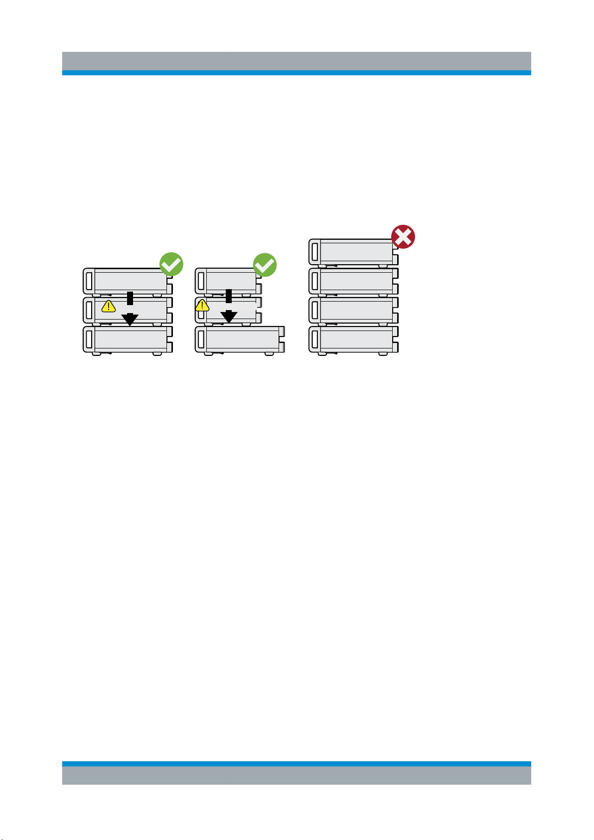
3. WARNING! A stack of products can fall over and cause injury. Never stack
more than three products on top of each other. Instead, mount them in a rack.
Stack as follows:
● It is best if all products have the same dimensions (width and length).
● The overall load on the lowest product must not exceed 500 N.
● With smaller products on top of the lowest product, the overall load on the
lowest product must not exceed 250 N.
max. 500 N
Correct Different dimensions
max. 250 N
Too many instruments
4. NOTICE! Overheating can damage the product.
Prevent overheating as follows:
● Keep a minimum distance of 10 cm between the fan openings of the prod-
uct and any object in the vicinity.
● Do not place the product next to heat-generating equipment such as radiators or other products.
You can mount the product in a 19" rack.
To prepare the rack
1. Observe the requirements and instructions in "Setting up the product"
on page 8.
2. NOTICE! Insufficient airflow can cause overheating and damage the product.
Design and implement an efficient ventilation concept for the rack.
To mount the product in a rack
1. Use an adapter kit to prepare the product for rack mounting.
a) Order the rack adapter kit designed for the product. For the order number,
see data sheet.
19Getting Started 2116.1234.02 ─ 08
Page 20

R&S®VTS
Considerations for Test Setup
b) Mount the adapter kit. Follow the assembly instructions provided with the
adapter kit.
2. Lift the product to shelf height.
3. Grab the handles and push the product onto the shelf until the rack brackets
fit closely to the rack.
4. Tighten all screws at the rack brackets to secure the product at the rack.
To unmount the product from a rack
1. Loosen the screws at the rack brackets.
2. Remove the product from the rack.
3. If placing the product on a bench top again, unmount the adapter kit from the
product. Follow the instructions provided with the adapter kit.
Preparing for Use
4.4 Considerations for Test Setup
Cable selection and electromagnetic interference (EMI)
Electromagnetic interference (EMI) can affect the measurement results.
To suppress electromagnetic radiation during operation:
●
Use high-quality shielded cables, especially for connecting the following:
– USB interfaces: Use double-shielded cables no longer than 1 m. Use only
USB devices that remain within the permissible EMI limits.
– DVI interface: Use a cable shielded with ferrite cores.
– 1000 BASE-T: Use category 7 cables.
●
Always terminate open cable ends.
●
Ensure that connected external devices comply with EMC regulations.
Signal input and output levels
Information on signal levels is provided in the data sheet. Keep the signal levels
within the specified ranges to avoid damage to the product and connected devices.
20Getting Started 2116.1234.02 ─ 08
Page 21

R&S®VTS
Connecting External USB Devices
Preparing for Use
4.5 Connecting to Power
For safety information, see "Connecting to power" on page 9.
The R&S VTS is powered by alternating current.
1. Plug the AC power cable into the AC power connector on the rear panel of the
product. Only use the AC power cable delivered with the product.
2. Plug the AC power cable into a power outlet with ground contact.
The required ratings are listed next to the AC power connector and in the data
sheet.
Further information:
●
Chapter 5.2.1, "AC Power Supply Connector and Switch", on page 27
4.6 Connecting External USB Devices
Using the USB interfaces, you can directly connect USB devices to the R&S VTS.
This number can be increased as necessary by using USB hubs.
Due to the large number of available USB devices, there is almost no limit to the
possible expansions. In the following, USB devices that can be useful are listed.
●
Memory stick for easy transfer of data to/from a computer (e.g. firmware
updates). See Chapter 4.6.1, "Memory Stick", on page 22.
●
External drives for easy installation of firmware applications. See Chap-
ter 4.6.2, "External Drive", on page 22.
●
Printer for printing measurement results.
To install a USB device
1. Connect the USB device to the R&S VTS. You can connect a USB device during operation because all USB devices are Plug and Play.
Windows 7 automatically searches for a suitable device driver.
2. If Windows 7 does not find a suitable driver, it prompts you to specify a directory that contains the driver software. If the driver software is on a CD-ROM,
connect a USB CD–ROM drive to the R&S VTS before proceeding.
21Getting Started 2116.1234.02 ─ 08
Page 22

R&S®VTS
To uninstall a USB device
► Disconnect the USB device from the R&S VTS at any time convenient.
Windows 7 immediately detects the change in the hardware configuration and
deactivates the corresponding driver.
Preparing for Use
Switching On or Off
4.6.1 Memory Stick
The R&S VTS has a disk drive. You can exchange data by using a memory stick
which you plug into one of the USB interfaces. The memory stick is automatically
assigned a free drive letter and you can use Windows Explorer to transfer data.
4.6.2 External Drive
You can use the USB interface to supply the power for an external hard disk drive
(HDD). Make sure that the maximum current suffices the power requirement of
the HDD. For USB 2.0, the maximum current is limited to 500 mA. With a Y cable,
you can use a second USB port as additional power supply.
4.7 Switching On or Off
The power switch is at the rear panel of the R&S VTS, see Chapter 5.2.1, "AC
Power Supply Connector and Switch", on page 27.
To switch on the product
The product is off but connected to power.
► Set the switch on the power supply to position [I].
The R&S VTS starts booting:
● The installed BIOS version and some of the computer features are dis-
played on the screen for a few seconds.
● The Windows 7 operating system is booted, followed by the R&S VTS
firmware.
● A self-test is performed.
After booting is completed, the main screen of the R&S VTS is displayed, and
the R&S VTS is ready for operation.
22Getting Started 2116.1234.02 ─ 08
Page 23

R&S®VTS
Checking the Provided Options
The configuration settings that were active before the R&S VTS was last shutdown are automatically restored.
Use the "File" dialog to load another instrument setting. For details, see the user
manual or the help system.
To switch off the R&S VTS
1. Check the status displays on the front panel of the R&S VTS. If the REMOTE
status display on the front panel is on, do not switch off the R&S VTS. Someone else is using the R&S VTS by remote control. See also Chapter 5.1.1,
"Status LEDs", on page 26.
2. NOTICE! Risk of losing data. If you set the power switch to the [O] position
before the R&S VTS settings have been saved, the current settings are lost.
Set the AC switch on the rear panel of the R&S VTS to the [O] position.
Preparing for Use
None of the LEDs on the front panel is lit.
4.8 Checking the Provided Options
The R&S VTS can be equipped with options. To check whether the installed
options correspond to the options indicated on the delivery note, proceed as follows.
Connect an external monitor or use remote operation (for details see user manual).
1. In the toolbar, click
2. Select the "SW/HW Equipment" tab.
3. Under "Hardware Configuration", check the availability of the hardware
options as indicated in the delivery note.
.
4. Under "Installed Software", check the availability of the software options as
indicated in the delivery note.
Further information:
●
User manual or the help system.
23Getting Started 2116.1234.02 ─ 08
Page 24

R&S®VTS
For an overview of the all options available for the R&S VTS, refer to the Rohde &
Schwarz Homepage.
Preparing for Use
Turn-On Tests
4.9 Turn-On Tests
During power-on and on an ongoing basis during operation, the R&S VTS automatically monitors the main instrument functions. If an error is detected, a message is displayed. Read the description of the error or warning carefully.
Besides automatic monitoring of instrument functions, the R&S VTS also offers
the following way of ensuring proper operation.
24Getting Started 2116.1234.02 ─ 08
Page 25
R&S®VTS
Instrument Tour
Front Panel
5 Instrument Tour
In this manual, the front and rear panel of the base unit are described. In the user
manual or the help system, this chapter also includes the following:
●
Description of the modules that you can optionally install
●
Information on pin assignments
For information on permissible input and output levels, see the data sheet.
Electromagnetic interference (EMI) can affect the measurement results. To
avoid any impact, follow the instructions in "Cable selection and electro-
magnetic interference (EMI)" on page 20.
The meanings of the labels on the product are described in Chapter 1.2, "Labels
on the Product", on page 10.
5.1 Front Panel
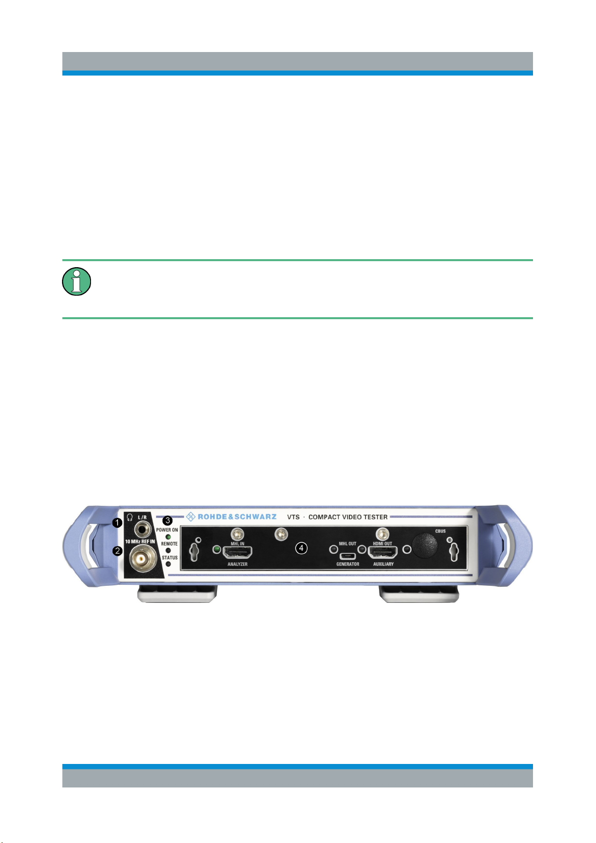
This chapter provides an overview of the controls and connectors on the front
panel. Each control or connector is briefly described along with a reference to the
chapters containing detailed information about its usage.
Figure 5-1: Front panel view
1 = Headphones
2 = Reference frequency input
3 = Status LEDs
4 = Module (example)
25Getting Started 2116.1234.02 ─ 08
Page 26

R&S®VTS
5.1.1 Status LEDs
See (3) in Figure 5-1.
The basic state is indicated by LEDs.
POWER ON
Displays the power supply status.
●
LED off: No power is supplied. R&S VTS is switched off.
●
LED green: Power is supplied.
REMOTE
Displays the remote control status.
●
LED off: R&S VTS is not used for remote control.
Instrument Tour
Front Panel
●
LED green: R&S VTS is connected to the LAN host.
STATUS
Displays the error status.
●
LED green: no warning or error is present.
●
LED yellow: a warning is present, but no error.
●
LED red: an error is present.
5.1.2 Headphones
See (1) in Figure 5-1.
For safety information, see "Connecting headphones" on page 10.
The jack socket for the L/R analog audio output provides the Windows system
sound. The socket is intended for connecting headphones or an active loudspeaker.
5.1.3 10 MHz REF IN
See (2) in Figure 5-1.
BNC connector. Input for the reference frequency.
26Getting Started 2116.1234.02 ─ 08
Page 27
R&S®VTS
Instrument Tour
Rear Panel
See the user manual or the help system.
5.2 Rear Panel
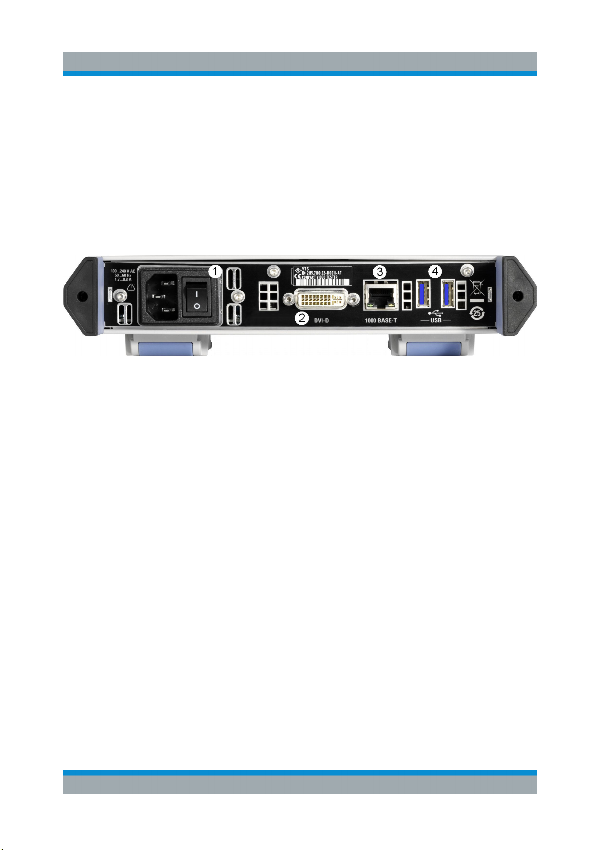
This chapter provides an overview of the controls and connectors on the rear
panel. Each control or connector is briefly described along with a reference to the
chapters containing detailed information about its usage.
Figure 5-2: Rear panel view
1 = AC power supply connector and switch
2 = Port to connect a monitor
3 = 1000 Base-T interface
4 = USB interfaces type A
5.2.1 AC Power Supply Connector and Switch
See (1) in Figure 5-2.
Observe the safety instructions in "Connecting to power" on page 9.
The IEC 320/EN 60320 AC power supply connector and the AC power switch are
combined (type C14). For the ratings of the power supply, refer to the data sheet.
The AC power switch is on the right of the AC power connector.
Switch positions:
●
[I]: The R&S VTS is in operation.
●
[O]: The entire instrument is disconnected from the AC power supply.
Further information:
●
Chapter 4.5, "Connecting to Power", on page 21
●
Chapter 4.7, "Switching On or Off", on page 22
27Getting Started 2116.1234.02 ─ 08
Page 28
R&S®VTS
Instrument Tour
Rear Panel
5.2.2 DVI Port
See (2) in Figure 5-2.
DVI-D socket. Output for the monitor signal of the built-in computer. The connected computer monitor needs to provide a resolution of 1024x768 pixels or higher.
You can use a DVI-I cable for connecting R&S VTS and display, but the
analog video interface (pins C1 to C4) is not provided by the R&S VTS.
5.2.3 1000 BASE-T
See (3) in Figure 5-2.
1 gigabit LAN interface (1000 Base-T). Used to connect the R&S VTS to a local
network for remote control, remote operation, printouts and data transfer. The
assignment of the RJ.45 CAT5 connector supports twisted-pair category 7
UTP/STP cables in a star configuration (UTP stands for "unshielded twisted pair",
and STP for "shielded twisted pair").
Do not connect or disconnect the network cable until the instrument is
switched off. Otherwise, the network connection cannot be reliably detected.
Electromagnetic interference (EMI) can affect the measurement results. To
avoid any impact, follow the instructions in "Cable selection and electro-
magnetic interference (EMI)" on page 20.
Further information:
●
Chapter 6, "Operating the R&S VTS in a LAN", on page 31
●
See user manual or the help system for remote control using the Ethernet.
5.2.4 USB Interfaces
See (4) in Figure 5-2.
USB 3.0 (universal serial bus) interfaces of the type A (host USB). Used to connect external devices like a keyboard, mouse, printer, memory stick, or to perform
a firmware update.
28Getting Started 2116.1234.02 ─ 08
Page 29
R&S®VTS
Instrument Tour
Rear Panel
Further information:
●
Chapter 4.6, "Connecting External USB Devices", on page 21
Electromagnetic interference (EMI) can affect the measurement results. To
avoid any impact, follow the instructions in "Cable selection and electro-
magnetic interference (EMI)" on page 20.
5.2.5 HDMI Connector
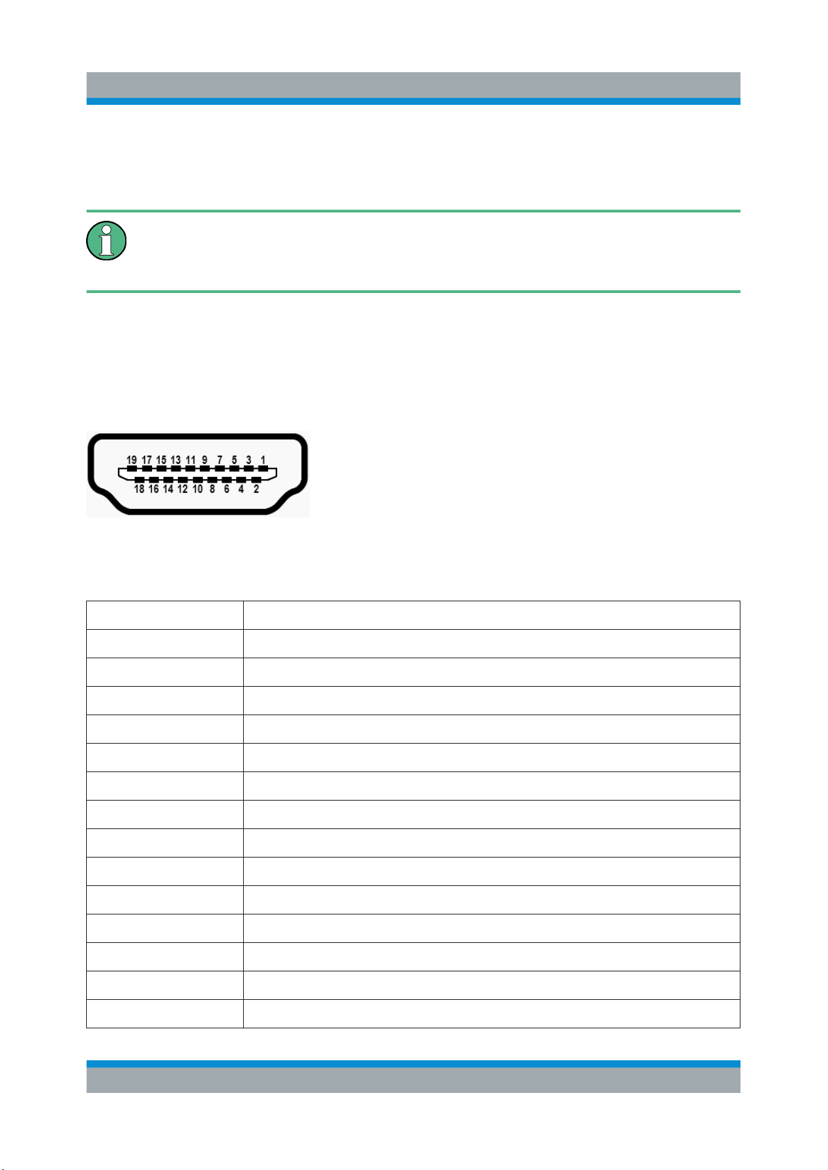
The HDMI type A socket is used in several optional modules. The pin assignment
and pin assignment are as follows.
Figure 5-3: HDMI type A socket
Table 5-1: Pin assignment
Pin Description
1 TMDS data2+
2 TMDS data2 shield
3 TMDS data2–
4 TMDS data1+
5 TMDS data1 shield
6 TMDS data1–
7 TMDS data0+
8 TMDS data0 shield
9 TMDS data0–
10 TMDS clock+
11 TMDS clock shield
12 TMDS clock–
13 CEC
14 Reserved (not connected)
29Getting Started 2116.1234.02 ─ 08
Page 30
R&S®VTS
Pin Description
15 SCL
16 SDA
17 DDC/CEC ground
18 +5 V power (+5 V / 500 mA)
19 Hot plug detect
Instrument Tour
Rear Panel
30Getting Started 2116.1234.02 ─ 08
Page 31

R&S®VTS
Operating the R&S VTS in a LAN
Connecting the R&S VTS to a Network
6 Operating the R&S VTS in a LAN
The R&S VTS is equipped with a network interface and can be connected to an
Ethernet LAN (local area network). The network card operates with 1000 Mbit
Ethernet IEEE 802.3ab. The TCP/IP network protocol and the associated network
services are preconfigured.
To be able to exchange data within a local area network (LAN), every computer or
R&S VTS that is connected must have a unique IP address or a unique computer
name. Access between different users is managed with access authorizations.
Provided the appropriate rights have been assigned and the Window 7 firewall
configuration is adapted accordingly, the interface can be used e.g. for transferring data, printing on network printers, operating/controlling the R&S VTS from a
remote computer.
To use network resources, access must be granted. To share files on the
R&S VTS with other network users, access to R&S VTS resources, e.g. the hard
drives, must also be granted. All these administration tasks are normally performed by a network administrator using the Windows 7 Start menu (for details
refer to the Windows 7 documentation). Contact your network administrator for
access authorizations.
User name and password of the R&S VTS are factory-set. The user name is used
for auto login, access authorization and remote operation.
For further information:
●
Chapter 7.1.1, "Login", on page 37
●
Chapter 5.2.3, "1000 BASE-T", on page 28
●
User manual or help system for details on remote operation and remote control.
6.1 Connecting the R&S VTS to a Network
Before connecting the R&S VTS to a network or configuring a network, do the following:
●
Consult your network administrator.
31Getting Started 2116.1234.02 ─ 08
Page 32

R&S®VTS
Connecting the R&S VTS to a Computer
●
If your network does not support DHCP or if you choose to disable dynamic
TCP/IP configuration, you must assign valid address information before connecting the R&S VTS to the LAN.
Errors may affect the entire network.
Efficient virus protection is a prerequisite for secure operation in the network.
Never connect the R&S VTS to a network without proper protection against a
virus infection, as doing so may cause damage to the R&S VTS firmware.
To connect the R&S VTS to a network
1. Fulfill all prerequisites mentioned above.
2. Make sure that the R&S VTS is switched off. This is the only way to ensure
that the network connection is reliably detected and any disruptions during the
operation of the R&S VTS are avoided.
Operating the R&S VTS in a LAN
3. Connect the R&S VTS to the network using a CAT-5e cable or better.
4. Switch on the R&S VTS.
To disconnect the R&S VTS from a network
1. Make sure that the R&S VTS is switched off.
2. Disconnect the R&S VTS from the network.
6.2 Connecting the R&S VTS to a Computer
How to set up a LAN connection between an R&S VTS and a single computer
without integration into a larger network depends on the operating system installed on the computer.
6.2.1 Windows 7 Operating System
If Windows 7 is installed on the computer, you can set up a LAN connection really
fast.
1. Activate DHCP on both the computer and the R&S VTS.
32Getting Started 2116.1234.02 ─ 08
Page 33

R&S®VTS
2. Connect the computer and the R&S VTS with a standard RJ.45 cross-over
cable (LAN cable).
After approx. 16 seconds, the connection is established.
3. To address the R&S VTS, use the computer name.
Further information:
●
" Querying the computer name using the firmware" on page 34
Operating the R&S VTS in a LAN
Configuring the Network Card
6.2.2 Other Operating Systems
If Windows 7 is not installed on the computer, you need to assign IP addresses.
1. Assign an IP address to the R&S VTS and the computer.
The IP addresses 192.168.xxx.yyy are available for use here. xxx and yyy can
assume values of 1 to 255. The value for the subnet mask is 255.255.255.0.
2. Connect the R&S VTS and the computer with a standard RJ.45 cross-over
cable (LAN cable).
3. To address the R&S VTS, use the assigned IP address.
6.3 Zero Configuration Networking
The R&S mDNS service is installed with the firmware. Using this service, you can
connect to a network automatically. You do not need to set up services, such as
dynamic host configuration protocol (DHCP) and domain name system (DNS), or
configure the network settings manually as described in Chapter 6.4, "Configuring
the Network Card", on page 33.
6.4 Configuring the Network Card
Under Windows 7, network card drivers do not need to be installed separately. If
the R&S VTS is connected to the LAN, Windows 7 automatically detects the network connection and activates the required drivers.
33Getting Started 2116.1234.02 ─ 08
Page 34
R&S®VTS
The configuration tasks depend on whether your network has a DHCP server or
not. They are performed in the "Setup" dialog.
For detailed information see the user manual or the help system.
If you are not familiar with LAN configurations, ask your network administrator.
If you use the R&S mDNS Service, you do not need to configure at all. For
details, see Chapter 6.3, "Zero Configuration Networking", on page 33.
Networks with DHCP Server
The R&S VTS is preconfigured for networks using the dynamic host configuration
protocol (DHCP). In such networks, the R&S VTS is automatically assigned a free
IP address. Identification in the network is based on the use of a unique computer
name.
Operating the R&S VTS in a LAN
Configuring the Network Card
Every R&S VTS is assigned an individual computer name at the factory. It is displayed as part of the window title of the application.
If necessary, you can change the computer name using the firmware or the Windows 7 Start menu (for details refer to the Windows 7 documentation).
Querying the computer name using the firmware
In the firmware, "host name" is used as synonym for "computer name".
1. If the R&S VTS has a default computer name, the computer name is displayed in the title bar of the application.
2. If no default computer name is displayed, do the following.
a) In the toolbar, click .
b) On the "System" tab, under "LAN Services", select the "Host Name" field.
3. Read out the name.
Naming rule for the default computer name
The default computer name is composed as follows:
<instrument short name>-<serial number>
Example: VTS-100104
34Getting Started 2116.1234.02 ─ 08
Page 35

R&S®VTS
The serial number consists of 6 digits and is printed on the cabinet of the
R&S VTS.
Networks without DHCP Server
In networks that assign fixed IP addresses, the network administrator usually configures the network card. Contact your network administrator. The IP address is
set using the firmware or the Windows 7 Start menu (for details refer to the Windows 7 documentation).
Entering the IP address using the firmware
Operating the R&S VTS in a LAN
Firewall Settings
1. In the toolbar, click
2. On the "System" tab, under "LAN Services", select the "IP Addresses" field.
3. Enter the IP address.
.
6.5 Firewall Settings
By default, the Windows Firewall is activated to protect the R&S VTS from an
attack of hostile users and programs. The Windows Firewall suppresses all network communication which is not initialized by the R&S VTS itself or which is not
defined as an exception.
To enable data transfer or to allow access to the R&S VTS, define exceptions
using the Windows 7 Start menu. For details refer to the Windows 7 documentation or contact your network administrator for support.
35Getting Started 2116.1234.02 ─ 08
Page 36

R&S®VTS
Operating the R&S VTS in a LAN
Firewall Settings
36Getting Started 2116.1234.02 ─ 08
Page 37

R&S®VTS
Installed Software
Operating System
7 Installed Software
The firmware and the operating system are already installed on the R&S VTS.
Further information:
●
Performing a firmware update: see the release notes.
●
Installing software options
See the installation instructions for options or the user manual.
7.1 Operating System
The R&S VTS is equipped with the Windows 7 Embedded operating system in
the 32-bit version. When the R&S VTS is delivered, the operating system is configured for optimum operation. Changes to the system settings are required only if
you install peripherals such as a keyboard and printer or if you configure the network and the settings do not conform to the default settings.
To prevent malfunctions and to avoid instrument repair, only install service packs
approved by Rohde & Schwarz. In particular, do not use service packs for other
Windows 7 editions.
7.1.1 Login
Windows 7 requires that you identify yourself by entering a user name and password in a login window. The R&S VTS provides a factory–installed auto login
function, i.e. login is carried out automatically in the background. The ID used for
auto login has administrator rights.
User name and password are factory-set as follows.
●
User name = instrument
●
Password: A label on the casing of the R&S VTS indicates the default
password. If there is no such label, the default password is 894129.
37Getting Started 2116.1234.02 ─ 08
Page 38

R&S®VTS
Backup and Restore Application
If the R&S VTS is connected to a network and if the login data under Windows 7
and on the network is identical, you log on to operating system and the network at
the same time.
Installed Software
7.1.2 Windows 7 Start Menu
The Windows 7 Start menu provides access to the Windows 7 functionality and
the installed programs. Under "Control Panel", the system settings are grouped.
For details, see the Windows 7 documentation.
To open the Start menu
► In the toolbar, click
.
7.2 Additional Software
The instrument is equipped with the Windows 7 operating system. Additional software can therefore be installed on the instrument. The use and installation of
additional software can impair instrument function. Thus, run only programs that
Rohde & Schwarz has tested for compatibility with the instrument software.
The drivers and programs used on the instrument under Windows 7 have been
adapted to the instrument. Modify existing instrument software only by using
update software released by Rohde & Schwarz.
7.3 Backup and Restore Application
Using the backup and restore application, you can back up the instrument installations and their configuration so that they can be restored if necessary. When
restoring, you can choose between various states.
●
Factory default state
If, for example, the system crashes, you can restore the factory default state.
●
Intermediate states that you have saved
For example, you can back up the current system partition before a firmware
update or provide different system configurations for different environments.
38Getting Started 2116.1234.02 ─ 08
Page 39
R&S®VTS
Backup and Restore Application
In the restore process, the system partition is deleted, formatted and written
newly. The data partition is not affected.
Connect an external keyboard.
If the instrument does not have a monitor, connect also an external monitor.
To display the main dialog for backup and restore
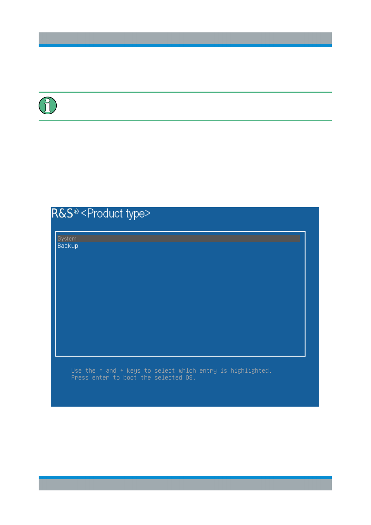
1. Restart the R&S VTS.
The boot screen is displayed. By default, "System" is selected. If you do not
perform the next step within 4 seconds, the dialog vanishes and the booting
process continues.
2. Select the "Backup" partition and press [ENTER].
Installed Software
The main dialog is displayed. It provides access to all functions of the backup
and restore application.
39Getting Started 2116.1234.02 ─ 08
Page 40
R&S®VTS
Installed Software
Backup and Restore Application
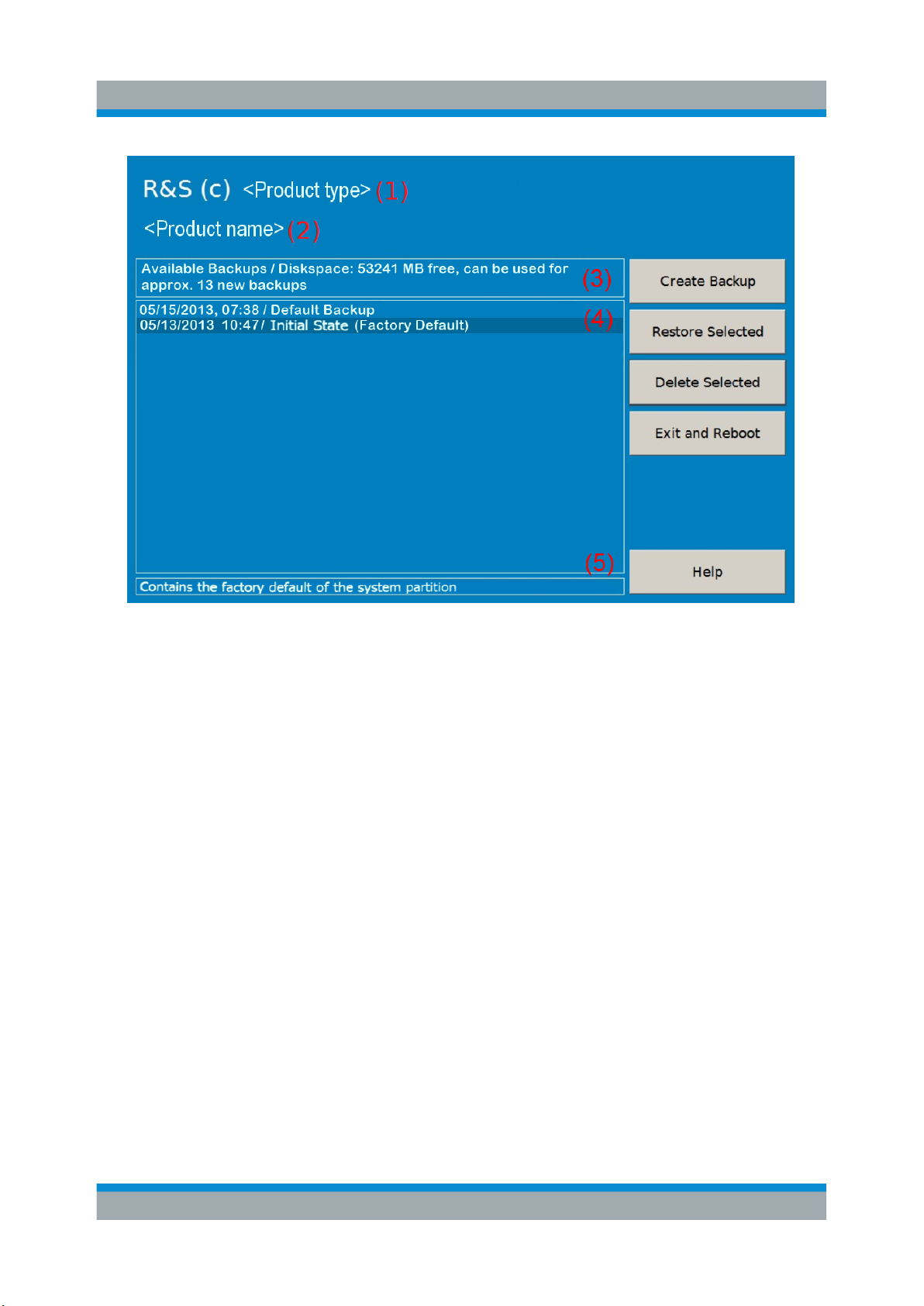
Figure 7-1: Main dialog (example)
(1) = Header showing instrument type
(2) = Header showing instrument name
(3) = Free memory space on backup partition
(4) = List of backups already created
(5) = Description of currently selected backup
To continue, see one of the following chapters:
●
Chapter 7.3.1, "Creating a Backup", on page 40
●
Chapter 7.3.2, "Restoring a Selected Backup Version", on page 41
●
Chapter 7.3.3, "Deleting a Backup", on page 42
7.3.1 Creating a Backup
Using this function, you can create a backup of the current instrument installation
and its configuration.
1. In the main dialog (see Figure 7-1), select "Create Backup".
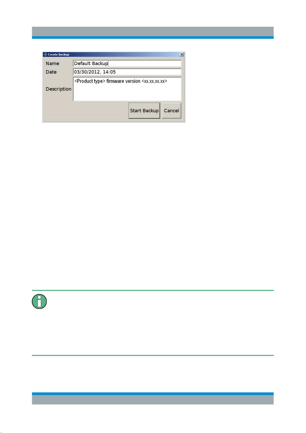
The "Create Backup" dialog is displayed. Under "Description", the current version of the firmware is displayed.
40Getting Started 2116.1234.02 ─ 08
Page 41
R&S®VTS
Backup and Restore Application
2. Enter a name for the backup and the date. If necessary, you can add information to the description.
3. Select "Start Backup".
During the backup process, a progress information dialog is displayed. You
can terminate at any time ("Cancel").
Installed Software
After the process has been finished, the dialog is closed automatically, and the
main dialog is displayed again.
Note: If you activate "Keep open when finished", the progress information dialog remains open until you close it.
4. In the main dialog, select "Exit and Reboot".
The backup and restore application is closed, and the R&S VTS is restarted.
7.3.2 Restoring a Selected Backup Version
Using this function, you can restore the selected instrument installation and its
configuration.
Malware protection
When restoring a backup, the Windows operating system and installed antimalware software are probably outdated. To minimize the risk of malware
threats after restoring a backup, verify and adjust the "Windows Update"
settings. Follow the recommendations from Rohde & Schwarz applicable to
your instrument. Also, install all Windows security updates that have been
published in the meanwhile.
1. In the main dialog (see Figure 7-1), select the backup you want to restore.
2. Select "Restore Selected".
41Getting Started 2116.1234.02 ─ 08
Page 42

R&S®VTS
Backup and Restore Application
3. In the "Restore Selected" dialog, select "Yes".
During the restoring process, a progress information dialog is displayed. You
can terminate at any time ("Cancel").
After the process has been finished, the application is closed automatically,
and the R&S VTS is restarted.
Note: If you activate "Keep open when finished", the progress information dialog remains open until you close it.
Installed Software
7.3.3 Deleting a Backup
Using this function, you can delete the selected instrument installation and its
configuration.
To provide space for new backups, you can remove older backups. The factory
default cannot be deleted.
1. In the main dialog (see Figure 7-1), select the backup you want to delete.
2. Select "Delete Selected".
3. In the "Delete Selected" dialog, select "Yes".
Note: You are not authorized to delete a factory default backup. If you have
selected one, an error message is displayed and the backup is not deleted.
4. In the main dialog, select "Exit and Reboot", or continue with Chapter 7.3.1,
"Creating a Backup", on page 40.
42Getting Started 2116.1234.02 ─ 08
Page 43
R&S®VTS
Contacting Customer Support
8 Contacting Customer Support
Technical support – where and when you need it
For quick, expert help with any Rohde & Schwarz product, contact our customer
support center. A team of highly qualified engineers provides support and works
with you to find a solution to your query on any aspect of the operation, programming or applications of Rohde & Schwarz products.
Contact information
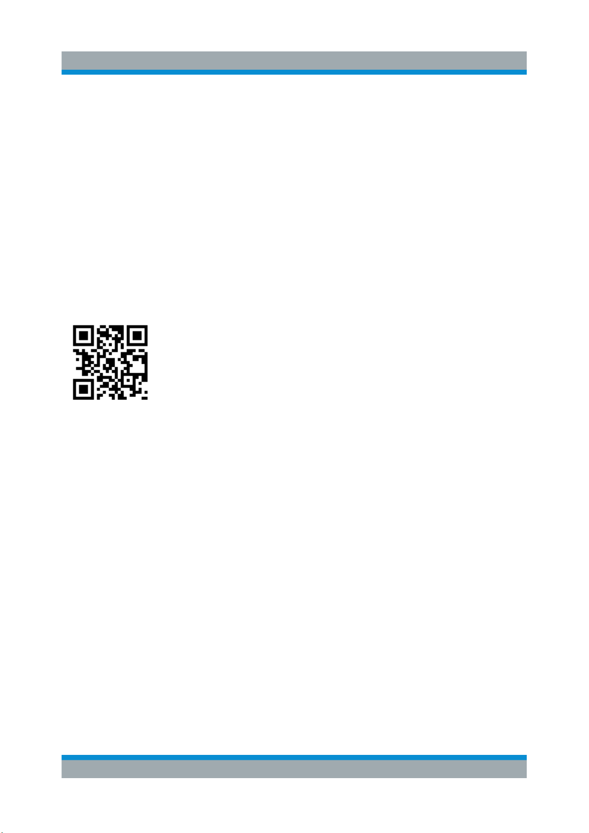
Contact our customer support center at www.rohde-schwarz.com/support, or fol-
low this QR code:
Figure 8-1: QR code to the Rohde & Schwarz support page
43Getting Started 2116.1234.02 ─ 08
Page 44

R&S®VTS
Contacting Customer Support
44Getting Started 2116.1234.02 ─ 08
Page 45

R&S®VTS
Index
Index
Symbols
10 MHz REF IN connector ...................... 26
1000 BASE-T connector ..........................28
A
AC power supply
Connecting to ......................................21
AC power supply connector .................... 27
AC power switch ......................................27
Administrator ID .......................................37
Application cards ..................................... 14
Application notes ..................................... 14
B
Backup
Creating .............................................. 40
Deleting ...............................................42
Main dialog ......................................... 38
Restoring ............................................ 41
Bench operation ...................................... 18
Brochures ................................................ 14
C
Carrying ...................................................17
Checking ................................................. 17
Provided options ................................. 23
Computer name .......................................34
Connecting
External devices ................................. 21
Power supply ...................................... 21
Connector ................................................28
10 MHz REF IN ...................................26
1000 BASE-T ......................................28
AC power supply .................................27
DVI ......................................................28
Headphones ....................................... 26
USB .................................................... 28
Customer support ....................................43
D
Data sheets ............................................. 14
Documentation overview ......................... 13
DVI connector ..........................................28
E
Electromagnetic interference
Preventing ...........................................20
EMC classes ........................................... 18
EMC precautions .....................................20
External devices ...................................... 21
External drive .......................................... 22
F
Firewall settings .......................................35
Firmware
Options ............................................... 23
Update ................................................ 37
Front panel .............................................. 25
G
Getting started .........................................13
H
HDD .........................................................22
Headphones connector ........................... 26
Help ......................................................... 13
Host name ............................................... 34
I
IP address
Changing ............................................ 33
L
Labels ......................................................10
LAN connector .........................................28
Lifting .......................................................17
Local area network (LAN) ..................28, 31
Login
Windows 7 .......................................... 37
M
Manual
Getting started .................................... 13
User manual ....................................... 13
Memory stick ........................................... 22
45Getting Started 2116.1234.02 ─ 08
Page 46

R&S®VTS
Index
N
Network
Configuring card ................................. 33
Connecting to ......................................31
Disconnecting from ............................. 31
O
Open source acknowledgment (OSA) .....14
Operating site .......................................... 18
Operating system .................................... 37
Options
Checking .............................................23
Firmware .............................................23
P
Password
Windows 7 .......................................... 37
POWER ON status LED ..........................26
Power supply
Connecting to ......................................21
Product documentation ........................... 13
Provided options
Checking .............................................23
R
Rack mounting ........................................ 19
Rear panel ...............................................27
Regulatory information .............................. 7
Release notes ......................................... 14
REMOTE status LED .............................. 26
Restore
Main dialog ......................................... 38
System partition
Backup ................................................40
Deleting selected version ....................42
Restoring selected version ................. 41
T
TCP/IP protocol
Configuring ......................................... 33
Tests ........................................................ 24
Tutorials ...................................................13
U
Unpacking ............................................... 17
USB connector
External devices ................................. 21
Type A .................................................28
User manual ............................................ 13
User name
Windows 7 .......................................... 37
W
Warning messages .................................. 11
White papers ........................................... 14
Windows 7 ...............................................37
Administrator ID .................................. 37
Login ................................................... 37
Password ............................................ 37
Start menu .......................................... 38
User name .......................................... 37
S
Safety information ..................................... 7
Safety instructions ................................... 14
Shipping damage inspection ................... 17
Software
Installing ..............................................38
Software options
Installing ..............................................37
Start menu ...............................................38
Status LED
POWER ON ........................................26
REMOTE ............................................ 26
STATUS .............................................. 26
46Getting Started 2116.1234.02 ─ 08
 Loading...