


R&S®SMW-K52/-K116/-K169/-K176
Digital Video Broadcasting Options
User Manual
(;ÙÑÜ2)
1175677802
Version 20

This document describes the following software options:
●
R&S®SMW-K52 DVB-H/T (1413.6090.xx)
●
R&S®SMW-K116 DVB-S2/S2X (1414.2630.xx)
●
R&S®SMW-K169 DVB-RCS2 (1413.8711.xx)
●
R&S®SMW-K176 DVB-S2X-E (1413.8686.xx)
This manual describes firmware version FW 5.00.166.xx and later of the R&S®SMW200A.
© 2022 Rohde & Schwarz GmbH & Co. KG
Muehldorfstr. 15, 81671 Muenchen, Germany
Phone: +49 89 41 29 - 0
Email: info@rohde-schwarz.com
Internet: www.rohde-schwarz.com
Subject to change – data without tolerance limits is not binding.
R&S® is a registered trademark of Rohde & Schwarz GmbH & Co. KG.
Trade names are trademarks of the owners.
1175.6778.02 | Version 20 | R&S®SMW-K52/-K116/-K169/-K176
The following abbreviations are used throughout this manual: R&S®SMW200A is abbreviated as R&S SMW, R&S®WinIQSIM2TM is
abbreviated as R&S WinIQSIM2; the license types 02/03/07/11/13/16/12 are abbreviated as xx.

R&S®SMW-K52/-K116/-K169/-K176
Contents
1 Welcome to the DVB options................................................................ 7
1.1 Accessing the DVB dialog............................................................................................8
1.2 What's new.....................................................................................................................9
1.3 Documentation overview..............................................................................................9
1.3.1 Getting started manual....................................................................................................9
1.3.2 User manuals and help................................................................................................... 9
1.3.3 Tutorials.........................................................................................................................10
1.3.4 Service manual............................................................................................................. 10
1.3.5 Instrument security procedures.....................................................................................10
1.3.6 Printed safety instructions............................................................................................. 10
1.3.7 Data sheets and brochures........................................................................................... 10
Contents
1.3.8 Release notes and open source acknowledgment (OSA)............................................ 10
1.3.9 Application notes, application cards, white papers, etc.................................................11
1.4 Scope............................................................................................................................11
1.5 Notes on screenshots.................................................................................................11
2 About the DVB options........................................................................12
2.1 Required options.........................................................................................................12
2.2 About DVB-H/T............................................................................................................ 12
2.3 About DVB-S2/S2X......................................................................................................13
3 DVB configuration and settings......................................................... 15
3.1 General settings.......................................................................................................... 15
3.2 DVB-T/DVB-H system settings...................................................................................19
3.3 DVB-T/DVB-H TPS settings........................................................................................ 22
3.4 DVB-S2/DVB-S2X System settings............................................................................26
3.5 MODCOD table configuration settings......................................................................35
3.6 TS header configuration settings.............................................................................. 37
3.7 GSE header settings................................................................................................... 39
3.8 BB header configuration settings............................................................................. 41
3.9 Super frame configuration settings.......................................................................... 43
3.9.1 SF Common settings.....................................................................................................44
3.9.2 SF Specific settings.......................................................................................................45
3User Manual 1175.6778.02 ─ 20

R&S®SMW-K52/-K116/-K169/-K176
3.9.3 Super frame information................................................................................................47
3.10 Beam hopping configuration settings.......................................................................48
3.11 DT configuration settings...........................................................................................51
3.12 DVB-RCS2 SF configuration settings....................................................................... 52
3.12.1 SF general settings....................................................................................................... 54
3.12.2 Frame structure settings............................................................................................... 57
4 Signal generation control....................................................................69
4.1 Filter/clipping settings................................................................................................69
4.1.1 Filter settings.................................................................................................................69
4.1.2 Clipping settings............................................................................................................72
4.2 Trigger settings........................................................................................................... 74
4.3 Marker settings............................................................................................................79
Contents
4.4 Clock settings..............................................................................................................81
4.5 Local and global connectors settings.......................................................................82
5 Remote-control commands.................................................................83
5.1 Common commands...................................................................................................84
5.2 Filter commands......................................................................................................... 89
5.3 Clipping commands....................................................................................................91
5.4 Trigger commands......................................................................................................93
5.5 Marker commands...................................................................................................... 97
5.6 Clock commands...................................................................................................... 100
5.7 DVB-T/DVB-H system commands........................................................................... 101
5.8 DVB-S2/DVB-S2X system commands..................................................................... 106
5.9 TPS commands......................................................................................................... 119
5.10 TS header commands...............................................................................................120
5.11 GSE header commands............................................................................................123
5.12 BB header commands.............................................................................................. 127
5.13 Super frame configuration commands................................................................... 129
5.14 Beam hopping configuration commands............................................................... 135
5.15 DVB-RCS2 SF configuration commands................................................................ 140
5.15.1 General configuration commands............................................................................... 142
5.15.2 BTU and grid configuration commands.......................................................................145
5.15.3 Section configiration commands................................................................................. 147
4User Manual 1175.6778.02 ─ 20

R&S®SMW-K52/-K116/-K169/-K176
Annex.................................................................................................. 157
A MODCOD Unique selection overview...............................................157
Glossary: Specifications................................................................... 162
List of commands.............................................................................. 163
Index....................................................................................................168
Contents
5User Manual 1175.6778.02 ─ 20

R&S®SMW-K52/-K116/-K169/-K176
Contents
6User Manual 1175.6778.02 ─ 20

R&S®SMW-K52/-K116/-K169/-K176
1 Welcome to the DVB options
The R&S SMW-K52/-K116 are firmware applications that add functionality to generate
signals in accordance with:
●
The DVB-H/T (Digital Video Broadcasting - Transmission System for Handheld Terminals) standard
●
The standards describing the second-generation DVB system for satellite communication DVB-S2 and the optional extension DVB-S2X.
DVB (digital video broadcasting) provides a communications infrastructure for powerful
transmission of MPEG-2-based data. Besides satellite-based (DVB-S), terrestrial
(DVB-T) and cable-bound (DVB-C) transmission schemes, the version (DVB-H) is for
portable/handheld terminals.
DVB-H is an extension to DVB and is compatible with the basic concept of the standard. The extensions bring advantages that are especially important for portable devices: low power consumption, small hardware and robustness against fading effects.
For DVB-H the current firmware supports non-hierarchical coding only.
Welcome to the DVB options
The DVB-S2 standard is introduced as successor the DVB-S for the transmission of
digital video broadcasts over satellite links. The DVB-S2X standard is an optional
extension of the DVB-S2 standard. DVB-S2X allows an efficiency gain of up to 51%
compared to DVB-S2. With that, higher data rates can be transported over the same
satellite transponder capacity.
The main advantages of the DVB-H / DVB-T digital standard option R&S SMW-K52
are:
●
Possibility to test both mobile communications standards (such as WCDMA 3GPP
FDD, TD-SCDMA, GSM/EDGE) and DVB-H or DVB-T using only one signal generator
●
Simple generation of standard-compliant DVB-H or DVB-T signals
Option R&S SMW-K116 extends the functionalities with the following key features:
●
Fully encoded DVB-S2 and DVB-S2X signal generation
●
Support of the stream types: transport stream (TS), generic packetized (GP),
generic continuos (GC), generic stream encapsulated high efficiency mode (GSEHEM)
●
Signal generation form arbitrary data sources and TS or GSE files
●
Channel coding according to the standard, incl. scrambling, interleaving, outer
code (BCH), inner code (LDPC) with varying code rates from 1/4 to 31/45
●
Support of all specified Walsh-Hadamard sequences for VL-SNR (very low signal
to noise ratio) mode
●
Configurable header information, incl. baseband (BB) header, VL-SNR header, TS
header, GSE header
●
Supported modulation schemes:
– For DVB-S2: QPSK, 8PSK, 16APSK, 32APSK
– For DVB-S2X: QPSK, 8APSK, 8PSK, 16APSK, 32APSK, 64APSK, 128APSK,
256APSK
7User Manual 1175.6778.02 ─ 20

R&S®SMW-K52/-K116/-K169/-K176
– For VL-SNR: QPSK, pi/2 BPSK
●
Pilot insertion and configuration
●
Signals suitable for testing of satellite transponders, components and ground
modems
Option R&S SMW-K169 extends the functionalities with the following key features:
●
Generating DVB-RCS2 signals according to ETSI EN 301 545-2
●
Energy dispersal with predefined scrambling sequence CRC16 and CRC32
●
Support of turbo FEC encoder linear modulation and Pi/2-BPSK, QPSK, 8PSK,
16QAM modulation schemes
●
Support of linear modulation and spread spectrum linear modulation bursts
●
Support of predefined waveforms as defined in Annex of ETSI EN 301 545-2
●
Support of user-defined waveforms
●
Support of multi-carrier and multi-section configuration.
Option R&S SMW-K176 extends the functionalities with the following key features:
●
Generating DVB-S2X-E signals
●
Support of super-frame format 4, 5, 6, 7
●
Physical layer header (PLH) according to Annex E of ETSI EN 302 307-2
●
Support SF-pilot and special VL-SNR pilots
●
Support of two ways scrambling
●
Support of beam-hopping with configurable dwell time.
Welcome to the DVB options
Accessing the DVB dialog
This user manual contains a description of the functionality that the application provides, including remote control operation.
All functions not discussed in this manual are the same as in the base unit and are
described in the R&S SMW user manual. The latest version is available at:
www.rohde-schwarz.com/manual/SMW200A
Installation
You can find detailed installation instructions in the delivery of the option or in the
R&S SMW service manual.
1.1 Accessing the DVB dialog
To open the dialog with DVB settings
► In the block diagram of the R&S SMW, select "Baseband > DVB".
A dialog box opens that displays the provided general settings.
The signal generation is not started immediately. To start signal generation with the
default settings, select "State > On".
8User Manual 1175.6778.02 ─ 20

R&S®SMW-K52/-K116/-K169/-K176
1.2 What's new
This manual describes firmware version FW 5.00.166.xx and later of the
R&S®SMW200A.
Compared to the previous version, it provides the new features listed below:
●
New option R&S SMW-K176 and settings to generate DVB-S2X-E signals, see:
– Chapter 3.9, "Super frame configuration settings", on page 43
– Chapter 3.10, "Beam hopping configuration settings", on page 48
– Chapter 3.11, "DT configuration settings", on page 51
●
New option R&S SMW-K169 and settings to generate DVB-RCS2 signals:
– Chapter 3.12, "DVB-RCS2 SF configuration settings", on page 52
1.3 Documentation overview
Welcome to the DVB options
Documentation overview
This section provides an overview of the R&S SMW user documentation. Unless specified otherwise, you find the documents on the R&S SMW product page at:
www.rohde-schwarz.com/manual/smw200a
1.3.1 Getting started manual
Introduces the R&S SMW and describes how to set up and start working with the product. Includes basic operations, typical measurement examples, and general information, e.g. safety instructions, etc. A printed version is delivered with the instrument.
1.3.2 User manuals and help
Separate manuals for the base unit and the software options are provided for download:
●
Base unit manual
Contains the description of all instrument modes and functions. It also provides an
introduction to remote control, a complete description of the remote control commands with programming examples, and information on maintenance, instrument
interfaces and error messages. Includes the contents of the getting started manual.
●
Software option manual
Contains the description of the specific functions of an option. Basic information on
operating the R&S SMW is not included.
The contents of the user manuals are available as help in the R&S SMW. The help
offers quick, context-sensitive access to the complete information for the base unit and
the software options.
All user manuals are also available for download or for immediate display on the Internet.
9User Manual 1175.6778.02 ─ 20

R&S®SMW-K52/-K116/-K169/-K176
1.3.3 Tutorials
The R&S SMW provides interactive examples and demonstrations on operating the
instrument in form of tutorials. A set of tutorials is available directly on the instrument.
1.3.4 Service manual
Describes the performance test for checking compliance with rated specifications, firmware update, troubleshooting, adjustments, installing options and maintenance.
The service manual is available for registered users on the global Rohde & Schwarz
information system (GLORIS):
https://gloris.rohde-schwarz.com
1.3.5 Instrument security procedures
Deals with security issues when working with the R&S SMW in secure areas. It is available for download on the Internet.
Welcome to the DVB options
Documentation overview
1.3.6 Printed safety instructions
Provides safety information in many languages. The printed document is delivered with
the product.
1.3.7 Data sheets and brochures
The data sheet contains the technical specifications of the R&S SMW. It also lists the
options and their order numbers and optional accessories.
The brochure provides an overview of the instrument and deals with the specific characteristics.
See www.rohde-schwarz.com/brochure-datasheet/smw200a
1.3.8 Release notes and open source acknowledgment (OSA)
The release notes list new features, improvements and known issues of the current
firmware version, and describe the firmware installation.
The open-source acknowledgment document provides verbatim license texts of the
used open source software.
See www.rohde-schwarz.com/firmware/smw200a
10User Manual 1175.6778.02 ─ 20

R&S®SMW-K52/-K116/-K169/-K176
1.3.9 Application notes, application cards, white papers, etc.
These documents deal with special applications or background information on particular topics.
See www.rohde-schwarz.com/application/smw200a and www.rohde-schwarz.com/
manual/smw200a
1.4 Scope
Tasks (in manual or remote operation) that are also performed in the base unit in the
same way are not described here.
In particular, it includes:
●
Managing settings and data lists, like saving and loading settings, creating and
accessing data lists, or accessing files in a particular directory.
●
Information on regular trigger, marker and clock signals and filter settings, if appropriate.
●
General instrument configuration, such as checking the system configuration, configuring networks and remote operation
●
Using the common status registers
Welcome to the DVB options
Notes on screenshots
For a description of such tasks, see the R&S SMW user manual.
1.5 Notes on screenshots
When describing the functions of the product, we use sample screenshots. These
screenshots are meant to illustrate as many as possible of the provided functions and
possible interdependencies between parameters. The shown values may not represent
realistic usage scenarios.
The screenshots usually show a fully equipped product, that is: with all options installed. Thus, some functions shown in the screenshots may not be available in your particular product configuration.
11User Manual 1175.6778.02 ─ 20

R&S®SMW-K52/-K116/-K169/-K176
2 About the DVB options
The digital video broadcasting (DVB) suite of standards described methods for data
and video signals transmission through different medium including cable, terrestrial,
mobile and satellite.
This section lists required options and provides brief background information on basic
terms and principles used in the DVB standards.
2.1 Required options
The basic equipment layout for generating DVB signals includes the:
●
Standard or wideband Baseband Generator (R&S SMW-B10/-B9)
●
Baseband main module (R&S SMW-B13) or wideband baseband main module
(R&S SMW-B13XT)
●
Frequency option (e.g. R&S SMW-B1003)
●
Digital standard DVB-H / DVB-T (R&S SMW-K52)
●
Digital standard DVB-S2 / DVB-S2X (R&S SMW-K116)
●
DVB-RCS2 (R&S SMW-K169)
●
DVB-S2X-E DVB-S2X Annex E (R&S SMW-K176)
(requires R&S SMW-K116)
About the DVB options
About DVB-H/T
You can generate signals via play-back of waveform files at the signal generator. To
create the waveform file using R&S WinIQSIM2, you do not need a specific option.
To play back the waveform file at the signal generator, you have two options:
●
Install the R&S WinIQSIM2 option of the digital standard, e.g. R&S SMW-K255 for
playing LTE waveforms
●
If supported, install the real-time option of the digital standard, e.g. R&S SMW-K55
for playing LTE waveforms
For more information, see data sheet.
2.2 About DVB-H/T
The Digital Video Broadcasting - Handheld (DVB-H) standard is based on the earlier
standard DVB-T, which is used for terrestrial digital broadcasting.
The block diagram on Figure 2-1 shows the components of the DVB-H transmission
system.
12User Manual 1175.6778.02 ─ 20

R&S®SMW-K52/-K116/-K169/-K176
Figure 2-1: Components of the transmission system DVB-H
The current firmware does not support hierarchical coding including low-priority coding.
The Low-Priority (LP) path of the MPEG-2 Stream indicates this by dotted squares of
the low-priority coding procedure.
About the DVB options
About DVB-S2/S2X
DVB-H provides features to meet the specific requirements for handheld, mobile terminals such as:
●
Power off some part of the reception chain to increase the battery duration
●
Ease access to the services when receivers switching to the next cell
●
Mitigate the effects of man-maid noise and severe mobile multipath channels on
the receiving capabilities
●
Offer sufficient flexibility and scalability to allow reception of services at various
speeds
●
Offer the flexibility to be used in various transmission bands and channel bandwidths
The basic technical extensions that make it possible to receive digital video broadcasting services on handheld terminals are:
●
4K mode and in-depth interleavers
●
Time-slicing
●
Forward error correction for multiprotocol encapsulated data (MPE-FEC)
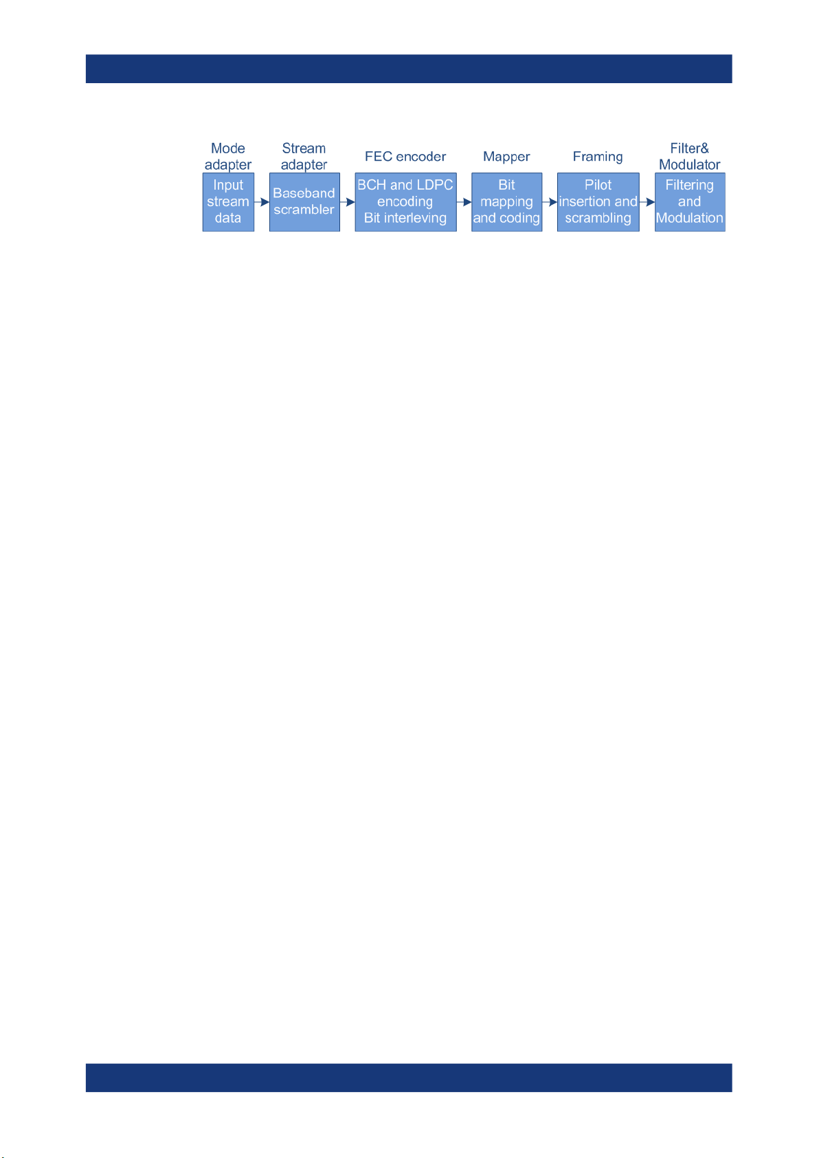
2.3 About DVB-S2/S2X
Figure 2-2 illustrates schematically the components of the DVB-S2/S2X transmission
systems. The block diagram is a simplified version of the DVB-S2 system specified in
the DVB standard.
13User Manual 1175.6778.02 ─ 20
R&S®SMW-K52/-K116/-K169/-K176
Figure 2-2: Components of the transmission system DVB-S2/S2X
FEC = Forward error correction
BCH = Bose-Chaudhuri-Hocquenghem multiple error correction binary block codes
LDPC = Low-density parity check
The main improvements of the second-generation DVB system for satellites (DVB-S2)
compared to DVB-S are:
●
Input stream adapter, suitable for operation with single and multiple input streams
and different formats (packetized or continuous)
●
FEC system based on LDPC codes concatenated with BCH codes
●
Range of code rates (from 1/4 up to 9/10);
Four constellations with different spectrum efficiency and optimized for operation
over non-linear transponders
●
Three predefined spectrum shapes with rolloff factors 0.35, 0.25 and 0.20
●
Adaptive coding and modulation (ACM) functionality for optimized channel coding
and modulation on a frame-by-frame basis.
About the DVB options
About DVB-S2/S2X
The DVB-S2X is an extension to the DVB-S2 standard. The DVB-S2X reuses the DVBS2 system architecture and improves it with the following:
●
Adds finer MODCOD steps, higher-order modulations and complex constellations
●
Three new sharper spectrum shapes
●
Defines the VL-SNR (low signal to noise ratio) mode for example for mobile applications
●
Optional periodic pilots and physical layer scrambles for easy synchronization
●
GSE-Lite compliant signaling and streaming
●
Adds a high-efficiency mode (GSE-HEM) intended to transport GSE and GSE-Lite
packets
14User Manual 1175.6778.02 ─ 20

R&S®SMW-K52/-K116/-K169/-K176
3 DVB configuration and settings
Access:
► Select "Baseband > DVB".
The remote commands required to define these settings are described in Chapter 5,
"Remote-control commands", on page 83.
● General settings......................................................................................................15
● DVB-T/DVB-H system settings............................................................................... 19
● DVB-T/DVB-H TPS settings....................................................................................22
● DVB-S2/DVB-S2X System settings........................................................................ 26
● MODCOD table configuration settings....................................................................35
● TS header configuration settings............................................................................ 37
● GSE header settings...............................................................................................39
● BB header configuration settings............................................................................ 41
● Super frame configuration settings......................................................................... 43
● Beam hopping configuration settings......................................................................48
● DT configuration settings........................................................................................ 51
● DVB-RCS2 SF configuration settings..................................................................... 52
DVB configuration and settings
General settings
3.1 General settings
Access:
► Select "Baseband > DVB > General".
This dialog provides general settings, the default and the "Save/Recall" settings,
and access to dialogs with further settings.
15User Manual 1175.6778.02 ─ 20

R&S®SMW-K52/-K116/-K169/-K176
Settings:
State..............................................................................................................................16
Set to Default................................................................................................................ 16
Save/Recall...................................................................................................................17
Generate Waveform File...............................................................................................17
DVB Standard............................................................................................................... 17
Hierarchy Mode.............................................................................................................17
VL-SNR Mode...............................................................................................................18
CCM/ACM.....................................................................................................................18
Number of PL Frames...................................................................................................18
Number of Super Frames..............................................................................................18
Number of Samples / Duration......................................................................................18
Sample Rate / Data Rate.............................................................................................. 18
Filter/Clipping Settings.................................................................................................. 19
State
Activates the standard and deactivates all the other digital standards and digital modulation modes in the same path.
Remote command:
[:SOURce<hw>]:BB:DVB:STATe on page 85
DVB configuration and settings
General settings
Set to Default
Calls the default settings. The values of the main parameters are listed in the following
table.
Parameter Value
State Not affected by "Set to default"
Number of Super-Frames 1
Hierarchy Mode Non-hierarchical
HP Source PN 23
Filter Type Cosine
Clipping Off
Cell Identification On
Time-Slicing On
ID [4 hex] 0000
MPE-FEC Off
PN Scrambler On
Outer Coder On
Outer Interleaver On
Inner Coder On
Rate 1/2
Inner Bit Interleaver On
16User Manual 1175.6778.02 ─ 20

R&S®SMW-K52/-K116/-K169/-K176
Parameter Value
Inner Symbol Interleaver On
Inner Interleaver Mode Native
TX Mode 2 K
OFDM/RF Bandwidth 8 MHz
Modulation QPSK
Alpha 1
Guard Interval 1/8
Remote command:
[:SOURce<hw>]:BB:DVB:PRESet on page 85
Save/Recall
Accesses the "Save/Recall" dialog, that is the standard instrument function for saving
and recalling the complete dialog-related settings in a file. The provided navigation
possibilities in the dialog are self-explanatory.
The settings are saved in a file with predefined extension. You can define the filename
and the directory, in that you want to save the file.
See also, chapter "File and Data Management" in the R&S SMW user manual.
DVB configuration and settings
General settings
Remote command:
[:SOURce<hw>]:BB:DVB:SETTing:CATalog? on page 85
[:SOURce<hw>]:BB:DVB:SETTing:LOAD on page 86
[:SOURce<hw>]:BB:DVB:SETTing:STORe on page 86
[:SOURce<hw>]:BB:DVB:SETTing:DELete on page 86
Generate Waveform File
With enabled signal generation, triggers the instrument to save the current settings of
an arbitrary waveform signal in a waveform file with predefined extension *.wv. You
can define the filename and the directory, in that you want to save the file.
Using the ARB modulation source, you can play back waveform files and/or process
the file to generate multi-carrier or multi-segment signals.
Remote command:
[:SOURce<hw>]:BB:DVB:WAVeform:CREate on page 86
DVB Standard
Selects the DVB standard to be used to generate the modulation signal.
Remote command:
[:SOURce<hw>]:BB:DVB:STANdard on page 87
Hierarchy Mode
Indicates the hierarchy coding mode, that is "Non-hierarchical".
The current firmware does not support hierarchical coding.
17User Manual 1175.6778.02 ─ 20

R&S®SMW-K52/-K116/-K169/-K176
"Non-hierarchical"
Remote command:
[:SOURce<hw>]:BB:DVB:DVBH|DVBT:HMODe on page 102
VL-SNR Mode
(requires option R&S SMW-K116)
For "DVB Standard > DVB-S2X", includes the VL-SNR (very low - signal to noise ratio)
header in the physical layer frame.
Remote command:
[:SOURce<hw>]:BB:DVB:DVBX:VSMode on page 87
CCM/ACM
Option: R&S SMW-K116
Selects whether constant coding and modulation (CCM) or adaptive coding and modu-
lation (ACM) communication is used.
In ACM mode, for instance, the receiver sends feedback information on received signal
quality. Depending on this feedback, the channel coding and modulation is optimized
on a frame-by-frame basis.
Remote command:
[:SOURce<hw>]:BB:DVB:DVBS|DVBX:BHConfig:CACM on page 127
DVB configuration and settings
General settings
The high priority input is used.
Number of PL Frames
Option: R&S SMW-K116
For "DVB Standard > DVB-S2/S2X", sets the number of the transmitted frames.
Remote command:
[:SOURce<hw>]:BB:DVB:DVBS|DVBX:FRAMes on page 88
Number of Super Frames
For DVB-H/-T, each super frame consists of four OFDM frames.
Remote command:
[:SOURce<hw>]:BB:DVB:DVBH|DVBT:SFRames on page 87
Number of Samples / Duration
Requires "DVB Standard > DVB-H/T" and "State > On".
Displays the number of the transmitted samples and the signal duration.
Remote command:
[:SOURce<hw>]:BB:DVB:DVBH|DVBT:SAMPle:LENGth? on page 88
[:SOURce<hw>]:BB:DVB:DVBH|DVBT:DURation? on page 88
Sample Rate / Data Rate
Requires "DVB Standard > DVB-H/T" and "State > On".
Displays the sample rate and data rate.
18User Manual 1175.6778.02 ─ 20

R&S®SMW-K52/-K116/-K169/-K176
Remote command:
[:SOURce<hw>]:BB:DVB:DVBH|DVBT:SAMPle:RATE? on page 89
[:SOURce<hw>]:BB:DVB:DVBH|DVBT:DRATe? on page 89
Filter/Clipping Settings
Accesses the dialog for setting baseband filtering and clipping, see Chapter 4.1, "Filter/
clipping settings", on page 69.
3.2 DVB-T/DVB-H system settings
Access:
1. Select "DVB > DVB Standard > DVB-T/DVB-H"
2. Select "System".
DVB configuration and settings
DVB-T/DVB-H system settings
The dialog provides settings to configure the DVB system. The DVB system is displayed in form of a block diagram including all parameters necessary to configure
the high priority path of DVB the system.
Hierarchical coding is not supported, the low priority path is not configurable.
Settings:
HP Source, Select File..................................................................................................20
PN Scrambler................................................................................................................20
Outer Coder (RS)..........................................................................................................20
Outer Interleaver........................................................................................................... 20
Inner Coder................................................................................................................... 20
Rate...............................................................................................................................20
Inner Bit Interleaver.......................................................................................................21
Inner Symbol Interleaver...............................................................................................21
19User Manual 1175.6778.02 ─ 20

R&S®SMW-K52/-K116/-K169/-K176
Inner Interleaver Mode..................................................................................................21
Inner Interleaver Tx Mode.............................................................................................21
OFDM/RF Bandwidth....................................................................................................21
OFDM/RF Modulation................................................................................................... 21
OFDM/RF Alpha............................................................................................................21
OFDM/RF Guard Int......................................................................................................22
HP Source, Select File
Selects the data source for the high priority path.
Remote command:
[:SOURce<hw>]:BB:DVB:DVBH|DVBT[:HP|LP]:DATA on page 102
[:SOURce<hw>]:BB:DVB:DVBH|DVBT[:HP|LP]:DATA:DSELection on page 103
PN Scrambler
Activates PN scrambling. The data packets of the incoming transport stream are transformed to a pseudo random binary sequence (PRBS). This transformation is performed
to obtain a bit sequence that has a positive effect on the transmitted RF spectrum.
Remote command:
[:SOURce<hw>]:BB:DVB:DVBH|DVBT[:HP|LP]:PNSCrambler[:STATe]
on page 104
DVB configuration and settings
DVB-T/DVB-H system settings
Outer Coder (RS)
Activates the outer coder. The outer coder applies a Reed-Solomon error correction
code to the PRBS data stream.
Remote command:
[:SOURce<hw>]:BB:DVB:DVBH|DVBT[:HP|LP]:OCODer[:STATe] on page 103
Outer Interleaver
Activates the outer convolutional interleaver.
Remote command:
[:SOURce<hw>]:BB:DVB:DVBH|DVBT[:HP|LP]:OINTerleaver[:STATe]
on page 104
Inner Coder
Activates the inner coder. The inner coder is a punctured convolutional error-correcting
coder.
Remote command:
[:SOURce<hw>]:BB:DVB:DVBH|DVBT[:HP|LP]:ICODer[:STATe] on page 103
Rate
If "Inner Coder > On", selects the code rate of the inner coder.
For encoding incoming bits (m), the inner coder transforms the bits into a bit symbol
containing n bits. The ratio m/n is the code rate.
Remote command:
[:SOURce<hw>]:BB:DVB:DVBH|DVBT[:HP|LP]:ICODer:RATE on page 103
20User Manual 1175.6778.02 ─ 20

R&S®SMW-K52/-K116/-K169/-K176
Inner Bit Interleaver
Activates the inner bit interleaver.
The inner interleaver consists of a bit-wise interleaving followed by symbol interleaving.
Both interleaving processes are block based.
Remote command:
[:SOURce<hw>]:BB:DVB:DVBH|DVBT:IINTerleaver:BIT[:STATe]
on page 104
Inner Symbol Interleaver
Activates the inner symbol interleaver.
Remote command:
[:SOURce<hw>]:BB:DVB:DVBH|DVBT:IINTerleaver:SYMBol[:STATe]
on page 105
Inner Interleaver Mode
Selects the inner interleaver mode. Interleaver mode in-depth is available only for
transmission mode 2K and 4K.
"Native"
"In-depth"
Remote command:
[:SOURce<hw>]:BB:DVB:DVBH|DVBT:IINTerleaver:SYMBol:MODE
on page 104
DVB configuration and settings
DVB-T/DVB-H system settings
Available for all transmission modes ("Tx Mode").
Requires "Tx Mode > 2K/4K".
Inner Interleaver Tx Mode
Selects the transmission mode.
The transmission mode determines the number of the OFDM subcarriers.
For "Tx Mode > 8 K", the in-depth interleaver mode is not available. "Tx Mode > 4 K" is
available only for "Standard > DVB-H".
Remote command:
[:SOURce<hw>]:BB:DVB:DVBH|DVBT:IINTerleaver:SYMBol:TMODe
on page 105
OFDM/RF Bandwidth
Selects the system bandwidth.
Remote command:
[:SOURce<hw>]:BB:DVB:DVBH|DVBT:OFDM:BWIDth on page 105
OFDM/RF Modulation
Selects the constellation for the OFDM modulation.
Remote command:
[:SOURce<hw>]:BB:DVB:DVBH|DVBT:OFDM:MODulation on page 106
OFDM/RF Alpha
Displays the alpha value, that is fixed to "1" for non-hierachical coding.
Remote command:
[:SOURce<hw>]:BB:DVB:DVBH|DVBT:OFDM:ALPHa on page 105
21User Manual 1175.6778.02 ─ 20

R&S®SMW-K52/-K116/-K169/-K176
OFDM/RF Guard Int.
Selects the length of guard interval. The guard interval extends the length of the transmitted symbol. Guard interval values resemble fractions of a symbol period.
Remote command:
[:SOURce<hw>]:BB:DVB:DVBH|DVBT:OFDM:GINTerval on page 105
3.3 DVB-T/DVB-H TPS settings
Access:
1. Select "DVB > DVB Standard > DVB-T/DVB-H"
2. Select "TPS".
DVB configuration and settings
DVB-T/DVB-H TPS settings
The dialog allows you to select the bits to transmit via the TPS signal and displays
the status of the parameter bits.
Settings:
Cell Identification...........................................................................................................22
ID (hex)......................................................................................................................... 23
Time Slicing...................................................................................................................23
MPE FEC...................................................................................................................... 23
TPS Table......................................................................................................................23
Cell Identification
Activates TPS cell identification. If activated, the cell from which the signal comes from
is identified.
Remote command:
[:SOURce<hw>]:BB:DVB:DVBH|DVBT:TPS:ID:STATe on page 119
22User Manual 1175.6778.02 ─ 20

R&S®SMW-K52/-K116/-K169/-K176
ID (hex)
Sets the cell ID for cell identification.
The cell ID identifies the cell from which the signal is transmitted. This value is read by
the receiver if Cell Identification is activated.
Remote command:
[:SOURce<hw>]:BB:DVB:DVBH|DVBT:TPS:ID:PATTern on page 119
Time Slicing
Indicates the status of the time-slicing bit. If activated, the average power consumption
of the terminal is reduced.
The current firmware does not support generation of time-slicing information. Time slicing is always used for DVB-H and permanently disabled for DVB-T.
Remote command:
[:SOURce<hw>]:BB:DVB:DVBH|DVBT:TPS:TSLicing[:STATe]? on page 120
MPE FEC
Activates the multiprotocol encapsulation forward error correction bit. MPE-FEC must
be performed in the transport stream. This implementation does not support MPE-FEC.
Remote command:
[:SOURce<hw>]:BB:DVB:DVBH|DVBT:TPS:MFEC[:STATe] on page 120
DVB configuration and settings
DVB-T/DVB-H TPS settings
TPS Table
The TPS parameter bit table displays the status of the transmitted TPS parameter bits.
Table 3-1: TPS signaling information transmitted in DVB-H
Bit number Format Purpose
0 0/1 Initialization bit for the differential 2PSK modulation. The modulation
of the TPS initialization bit is derived from the PRBS sequence
1-16
Bits 1 to 16 of the TPS are the synchronization words for the TPS
blocks in the super-frames:
23User Manual 1175.6778.02 ─ 20

R&S®SMW-K52/-K116/-K169/-K176
Bit number Format Purpose
DVB configuration and settings
DVB-T/DVB-H TPS settings
17-22
23-24
25-26
0011010111101110 Synchronization word for the first and the third TPS block in each
super-frame
11001010000100001 Synchronization word for the second and the fourth TPS block in
each super-frame
010111 Cell identification is not transmitted (23 TPS bits in use)
011111 Cell identification information is transmitted (31 TPS bits in use)
100001 Cell identification information is transmitted for DVB-H (33 TPS bits in
00 Frame 1 in the super-frame
01 Frame 2 in the super-frame
10 Frame 3 in the super-frame
11 Frame 4 in the super-frame
00 QPSK
The first 6 bits of the TPS information is used as a TPS length indicator to signal the number of used bits of the TPS:
use)
Indicates the frame in the super-frame. Four frames constitute a
super-frame.
Indicates the constellation
27
28-29
30-32
01 16-QAM
10 64-QAM
11 Reserved
0 The native interleaver is used
1 The in-depth interleaver is used
00 Transmission in non-hierarchical mode
01 Alpha = 1
10 Alpha = 2
11 Alpha = 4
000 1/2
001 2/3
010 3/4
Indicates the interleaver mode. The in-depth interleaver can be used
for 2K and 4K transmission mode. For transmission mode 8K, only
the native interleaver is used:
Indicates the hierarchical transmission and the value of the alphafactor
Indicates the code rate for the HP transmission stream
011 5/6
24User Manual 1175.6778.02 ─ 20

R&S®SMW-K52/-K116/-K169/-K176
Bit number Format Purpose
DVB configuration and settings
DVB-T/DVB-H TPS settings
33-35
36-37
100 7/8
101 reserved
110 reserved
111 reserved
000 1/2
001 2/3
010 3/4
011 5/6
100 7/8
101 reserved
110 reserved
111 reserved
00 1/32
01 1/16
Indicates the code rate for the LP transmission stream
Indicates the value for the guard interval
38-39
40-47 Cell_id 32 bits are used for the cell ID.
48
49
50-53 reserved
10 1/8
11 1/4
00 2K mode
01 8K mode
10 4K mode
11 reserved
0 Time-slicing is not used
1 At least one elementary stream uses time-slicing
0 MPE-FEC is not used
1 At least one elementary stream uses MPE-FEC
Indicates the transmission mode
Every frame contains 8 bits. The 8 bits are used to identify the cell
from which the signal comes from.
Indicates the usage of time-slicing
Indicates the usage of MPE-FEC
54-67 xxxxxxxxxxxxxxxx BCH error protection
25User Manual 1175.6778.02 ─ 20

R&S®SMW-K52/-K116/-K169/-K176
3.4 DVB-S2/DVB-S2X System settings
Option: R&S SMW-K116
Access:
1. Select "DVB > DVB Standard" > "DVB-S2/DVB-S2X".
2. Select "CCM/ACM":
● "CCM" for constant coding and modulation
● "ACM" for adaptive coding and modulation
3. Select "System".
DVB configuration and settings
DVB-S2/DVB-S2X System settings
The dialog provides settings to configure the DVB system. The DVB system is displayed in form of a block diagram including all related parameters.
The provided settings depend on the selected DVB Standard and on whether constant coding and modulation (CCM) or adaptive coding and modulation (ACM)
communication is used.
The blocks indicate the first four logical signal processing parts:
● Mode adaptation:
Input stream configuration, incl. configuration of the header information
● Stream adaptation:
Baseband scrambling and FEC (forward error correction) encoding
● Constellation mapping:
Modulation and coding
● Pilot:
Insertion and scrambling of the optional pilot.
The last processing part is the baseband spectrum shaping. Find the required filter
parameters in the "Filter" dialog, see Chapter 4.1.1, "Filter settings", on page 69.
26User Manual 1175.6778.02 ─ 20

R&S®SMW-K52/-K116/-K169/-K176
Settings:
Stream Type..................................................................................................................27
Input Stream..................................................................................................................27
Data Source, Select File............................................................................................... 28
Complete PN Sequence................................................................................................29
BB Frames.................................................................................................................... 29
Data Length...................................................................................................................29
Auto Data Length.......................................................................................................... 29
TS Header Config......................................................................................................... 30
GSE Header Config...................................................................................................... 30
BB Header Config......................................................................................................... 30
CRC32.......................................................................................................................... 30
BB Scrambler................................................................................................................30
Outer Coder.................................................................................................................. 30
Inner Coder................................................................................................................... 30
CCM settings.................................................................................................................30
└ Rate................................................................................................................ 30
└ SF................................................................................................................... 31
└ MODCOD Unique........................................................................................... 31
└ Code Type.......................................................................................................32
└ MODCOD........................................................................................................32
└ Modulation...................................................................................................... 32
└ Pilot State........................................................................................................33
└ SF Config........................................................................................................33
└ BH Config........................................................................................................33
ACM settings.................................................................................................................33
└ Bit Interleaver..................................................................................................33
└ MODCOD Table Config...................................................................................33
Uncoded Mode..............................................................................................................34
PL Scrambler................................................................................................................ 34
Scr. Sequence...............................................................................................................34
Gold Sequence............................................................................................................. 34
DVB configuration and settings
DVB-S2/DVB-S2X System settings
Stream Type
Selects the type of input stream.
"Transport"
"GP"
"GC"
"GSE-HEM"
Remote command:
[:SOURce<hw>]:BB:DVB:DVBS|DVBX:STYPe on page 109
Input Stream
Indicates that the input stream is single (SIS).
Multiple input streams (MIS) are not supported.
Transport stream TS
Generic packetized
Generic continuous
Requires "DVB Standard > DVB-S2X".
Generic stream encapsulation, high efficiency mode (HEM) packetized.
27User Manual 1175.6778.02 ─ 20

R&S®SMW-K52/-K116/-K169/-K176
Remote command:
[:SOURce<hw>]:BB:DVB:DVBS|DVBX:ISTReam? on page 110
Data Source, Select File
Selects the data source.
The following standard data sources are available:
●
"All 0, All 1"
An internally generated sequence containing 0 data or 1 data.
●
"PNxx"
An internally generated pseudo-random noise sequence.
●
"Pattern"
An internally generated sequence according to a bit pattern.
Use the "Pattern" box to define the bit pattern.
●
"Data List/Select DList"
A binary data from a data list, internally or externally generated.
Select "Select DList" to access the standard "Select List" dialog.
– Select the "Select Data List > navigate to the list file *.dm_iqd > Select" to
select an existing data list.
– Use the "New" and "Edit" functions to create internally new data list or to edit
an existing one.
– Use the standard "File Manager" function to transfer external data lists to the
instrument.
See also:
●
Section "Modulation Data" in the R&S SMW user manual.
●
Section "File and Data Management" in the R&S SMW user manual.
●
Section "Data List Editor" in the R&S SMW user manual
DVB configuration and settings
DVB-S2/DVB-S2X System settings
"TS File, Select File"
For "DVB Standard > DVB-S2", uses a transport stream (TS) file as
data source. TS files are files with extension *.gts, *.ts or *.trp.
File extension Format Description
*.gts
*.trp
*.ts
Select "Select File" to access the standard "File Select" dialog.
"GSE File, Select File"
For "DVB Standard > DVB-S2X", uses a generic stream encapsulation (GSE) file as data source. GSE files are files with extension
*.gse.
Select "Select File" to access the standard "File Select" dialog.
Rohde & Schwarz
proprietary
MPEG-2 Standard DVB file format for HD video trans-
MPEG Standard digital container format for transmis-
port
Contains high definition transportation stream
sion and storage of audio, video, and program and system information protocol (PSIP)
data.
28User Manual 1175.6778.02 ─ 20

R&S®SMW-K52/-K116/-K169/-K176
Remote command:
[:SOURce<hw>]:BB:DVB:DVBS|DVBX:DATA on page 110
[:SOURce<hw>]:BB:DVB:DVBS|DVBX:DATA:
DSELection|TSELection|GSELection on page 111
[:SOURce<hw>]:BB:DVB:DVBS|DVBX:DATA:PATTern on page 110
Complete PN Sequence
Requires "Data Source > PNxx".
Activates transmission of the complete sequence of pseudo-random noise bits within
the baseband frame.
Remote command:
[:SOURce<hw>]:BB:DVB:DVBS|DVBX:CPNSequence:STATe on page 112
BB Frames
Requires "Data Source > PNxx" and "Complete PN Sequence > On".
Displays the number of baseband frames.
The number of baseband frames increases with the length of pseudo-random noise bit
sequence, see Table 3-2.
Table 3-2: PN sequence length and number of BB frames
DVB configuration and settings
DVB-S2/DVB-S2X System settings
Data source Number of baseband frames
PN 9 1
PN 11 1
PN 15 3
PN 16 5
PN 20 72
PN 21 143
PN 23 570
Remote command:
[:SOURce<hw>]:BB:DVB:DVBS|DVBX:BBFRames? on page 111
Data Length
If "Auto Data Length > Off", sets the data length in bytes.
The value is used to calculate the value of the parameter Total Length.
Remote command:
[:SOURce<hw>]:BB:DVB:DVBS|DVBX:DATA:LENGth on page 111
Auto Data Length
Defines, if the "Data Length" is set automatically or manually.
Remote command:
[:SOURce<hw>]:BB:DVB:DVBS|DVBX:ADLength:STATe on page 111
29User Manual 1175.6778.02 ─ 20

R&S®SMW-K52/-K116/-K169/-K176
TS Header Config
Requires "Stream Type > Transport". Accesses the transport stream header settings,
see Chapter 3.6, "TS header configuration settings", on page 37.
GSE Header Config
Requires "Stream Type > GSE-HEM". Accesses the GSE header settings, see Chap-
ter 3.7, "GSE header settings", on page 39.
BB Header Config
Accesses the baseband header settings, see Chapter 3.8, "BB header configuration
settings", on page 41.
CRC32
Activates CRC-32 check sum calculation.
The CRC-32 check sum is calculated and appended to the baseband frame
(BBFRAME). The BB header is excluded.
In detail, CRC-32 is calculated over the first (80+DFL-32) bits of the BBFRAME, and
inserted into the final 32 bits of the data field. The technique guarantees, that any
errors in the received BBFRAME can be reliably detected, as BCH error indicator is not
reliable. The CRC polynomial is as follows:
x32 + x26 + x23 + x22 + x12 + x11 + x10 + x8 + x7 + x5 + x4 + x2 + x + 1
Remote command:
[:SOURce<hw>]:BB:DVB:DVBS|DVBX:CRC[:STATe] on page 112
DVB configuration and settings
DVB-S2/DVB-S2X System settings
BB Scrambler
Activates baseband scrambling.
Remote command:
[:SOURce<hw>]:BB:DVB:DVBS|DVBX:BSCRambler[:STATe] on page 112
Outer Coder
Enables the BCH outer coder.
BCH codes are Bose-Chaudhuri-Hocquenghem multiple error correction binary block
codes.
Remote command:
[:SOURce<hw>]:BB:DVB:DVBS|DVBX:OCODer[:STATe] on page 113
Inner Coder
Applies LDPC (low-density parity check) encoding to data bits.
The inner coder is a punctured convolutional coder with error-correction.
Remote command:
[:SOURce<hw>]:BB:DVB:DVBS|DVBX:ICODer[:STATe] on page 113
CCM settings
The following settings require mode "CCM/ACM > CCM".
Rate ← CCM settings
Selects the code rate of the inner LDPC coder.
30User Manual 1175.6778.02 ─ 20
 Loading...