

Page 1

R&S®VENICE
S400/407/414-G2
User Manual
2906.1145.02
Version 12
Page 2

VENICE S
© 2022 Rohde & Schwarz GmbH & Co. KG
Hanomaghof 4, 30449 Hanover, Germany
Phone: +49-511-67807-0
Support: https://www.rohde-schwarz.com/support
Internet: https://www.rohde-schwarz.com
Subject to change – Data without tolerance limits is not binding. R&S® is a registered trademark of Rohde & Schwarz GmbH & Co. KG.
Trade names are trademarks of the owners.
Throughout this manual, products from Rohde & Schwarz are indicated without the ® symbol,
e.g. R&S®VENICE S is indicated as VENICE S.
2
User Manual | 2906.1145.02 - 12
Page 3

VENICE S
Contents
General .............................................................................................................7
About this Documentation....................................................................................................... 8
Required Reading ................................................................................................................8
Target Group ........................................................................................................................ 8
Additional Documentation .................................................................................................... 8
Safety ................................................................................................................9
For your Safety ....................................................................................................................... 10
General Notes ......................................................................................................................... 11
Product Description ......................................................................................13
Function .................................................................................................................................. 14
Models ..................................................................................................................................... 15
Features................................................................................................................................... 16
Channel Configuration ........................................................................................................ 16
Workflow-based Metadata .................................................................................................. 17
Audio Routing ..................................................................................................................... 24
Image Processing ............................................................................................................... 24
Timecode ............................................................................................................................ 25
Play After Write .................................................................................................................. 26
Type Plate and Serial Number ............................................................................................... 27
Type Plate .......................................................................................................................... 27
Serial Number .................................................................................................................... 28
Scope of Delivery ................................................................................................................... 29
The Front of the System ........................................................................................................ 30
Chassis Front ..................................................................................................................... 30
Left Control Panel ............................................................................................................... 30
Right Control Panel ............................................................................................................ 31
Hard Drives ........................................................................................................................ 32
The Rear of the System..........................................................................................................34
Back Panel ......................................................................................................................... 34
LTC In/Out .......................................................................................................................... 35
AES/EBU Audio .................................................................................................................. 36
Power Supply Unit .............................................................................................................. 36
Power Supply Indicator ...................................................................................................... 37
Out- or Input of Primary/Secondary Control Signals .......................................................... 38
Downconvert Video Output ................................................................................................ 38
In-/Output of Digital Video Signals ..................................................................................... 40
Network Interface Card (NIC) Connectors.......................................................................... 44
NIC Indicator ...................................................................................................................... 44
Inside the System ................................................................................................................... 46
System Cover ..................................................................................................................... 46
Cooling Fan Assembly ....................................................................................................... 47
Cooling Fans ...................................................................................................................... 48
Rescue Stick ...................................................................................................................... 49
User Manual | 2906.1145.02 - 12
3
Page 4

VENICE S
Pin Assignment ...................................................................................................................... 50
HD Sub-D Connector (LTC In/Out) .................................................................................... 50
HD Sub-D Connector (AES/EBU) ...................................................................................... 51
RJ45 Connector ................................................................................................................. 52
Serial Connector ................................................................................................................. 53
Video Connector .................................................................................................................54
Lynx CBL-AES1604 Cable ................................................................................................. 56
Network Ports ......................................................................................................................... 57
VENICE S Server Ports (Information) ................................................................................ 57
VENICE S Server Ports (Configuration) ............................................................................. 61
VENICE S Client Ports (Information) .................................................................................. 63
VENICE S Client Ports (Configuration) .............................................................................. 65
Installation and Configuration ..................................................................... 67
Installing the System .............................................................................................................. 68
Starting the System ................................................................................................................ 72
Configuring the System ......................................................................................................... 73
Log In ................................................................................................................................. 73
Network Configuration ........................................................................................................ 73
Integrating Software Service .............................................................................................. 73
System Update ...................................................................................................................74
Shutting Down the System .................................................................................................... 75
Operation ....................................................................................................... 77
Operating the System ............................................................................................................78
Usable Software and Protocols .......................................................................................... 78
VENICE UI ......................................................................................................................... 78
Playing Content .................................................................................................................. 79
Ingesting Content ...............................................................................................................79
Transforming Content ......................................................................................................... 80
File Management ................................................................................................................ 80
Configuring VENICE S Services ........................................................................................ 81
Configuring the Subtitles .................................................................................................... 84
Administration............................................................................................... 87
User Management................................................................................................................... 88
Changing the Passwords ................................................................................................... 88
Changing the User ID ......................................................................................................... 89
Adding Samba Users ......................................................................................................... 90
Creating a Backup Image ....................................................................................................... 91
Restoring the System............................................................................................................. 94
System Update ........................................................................................................................ 97
SNMP System Monitoring ...................................................................................................... 98
SNMP MIB files location ..................................................................................................... 98
Understanding SNMP Naming ........................................................................................... 98
Basic System Monitoring via SNMP ................................................................................... 99
Advanced System Monitoring via SNMP .......................................................................... 101
4
User Manual | 2906.1145.02 - 12
Page 5

VENICE S
Integration into an IP Network ............................................................................................. 111
Preconditions .................................................................................................................... 111
General Network Settings ................................................................................................ 112
Installing the IP Software .................................................................................................. 115
Channel Configuration ...................................................................................................... 115
Activating the SMPTE 2110 IP Interfaces ........................................................................ 116
Configuring the PTP Sync Mode ...................................................................................... 117
Configuring the PTP Parameters ..................................................................................... 119
Configuring the NMOS Node Settings .............................................................................. 120
NMOS Stream Configuration ............................................................................................ 120
Maintenance .................................................................................................135
Safety Instructions ............................................................................................................... 136
Removing and Mounting the System Cover ...................................................................... 138
Removing the System Cover ............................................................................................ 138
Installing the System Cover .............................................................................................. 139
Replacing a Power Supply Unit ........................................................................................... 140
Replacing a Hot Swappable Hard Drive ............................................................................. 142
Replacing a Cooling Fan Assembly .................................................................................... 144
Replacing a Cooling Fan .................................................................................................. 145
Replacing the Internal USB Memory Key ........................................................................... 147
Working with the R&S Installer (RSI) ......................................................... 149
Types of RSI Packages ........................................................................................................ 150
Using an RSI ......................................................................................................................... 151
RSI Troubleshooting ............................................................................................................ 153
Logs .................................................................................................................................. 153
Error Codes ...................................................................................................................... 153
Transport ......................................................................................................157
Safety Notes .......................................................................................................................... 158
Packing the System..............................................................................................................159
Troubleshooting ..........................................................................................161
Safety First - For you and your System .............................................................................. 162
Troubleshooting External Connections ............................................................................. 163
Troubleshooting the Video Subsystem .............................................................................. 164
Troubleshooting a USB Device ........................................................................................... 165
Troubleshooting a Wet System ........................................................................................... 166
Troubleshooting Power Supply Units ................................................................................ 167
Troubleshooting Power Source Problems ........................................................................ 167
Power Supply Unit Problems ............................................................................................ 167
Troubleshooting Cooling Problems ................................................................................... 168
Troubleshooting Cooling Fans ......................................................................................... 168
Troubleshooting an Internal USB Key ................................................................................ 169
Restarting a Single Channel ................................................................................................ 170
Disk Space Limit ................................................................................................................... 171
Technical Data .............................................................................................173
Declaration of Conformity (CE) ........................................................................................... 185
Index .............................................................................................................187
User Manual | 2906.1145.02 - 12
5
Page 6

VENICE S
6
User Manual | 2906.1145.02 - 12
Page 7

General
This chapter includes the following section:
GeneralVENICE S
● "About this Documentation" (page 8)
User Manual | 2906.1145.02 - 12
7
Page 8

General
About this Documentation
About this Documentation
This documentation informs you about the installation of the VENICE S hardware, a video server system by Rohde & Schwarz, its operation as well as all
connection possibilities. Furthermore, it describes maintenance tasks that
you may carry out on your own.
Required Reading
Each person who is responsible for installation, operation, maintenance or
setting of the system has to read and understand this manual.
Target Group
To use this manual you should have experience in handling video and
computer equipment.
When performing maintenance tasks on the hardware, you must be qualified
to work on, repair and test electrical equipment.
VENICE S
Additional Documentation
Following documents have to be heeded while working with VENICE S:
● Getting Started With Your System
● Data Sheet
● Safety, Environment and Regulatory Information
● Software Integration Guide
● Supported File Formats
The complete documentation can be downloaded from
https://gloris.rohde-schwarz.com after registering/logging in to access
restricted information. There you may find updated manuals and further
information as well.
8
User Manual | 2906.1145.02 - 12
Page 9

Safety
SafetyVENICE S
This chapter is divided into the following sections:
● "For your Safety" (page 10)
● "General Notes" (page 11)
User Manual | 2906.1145.02 - 12
9
Page 10

Safety
For your Safety
For your Safety
The product documentation helps you to use VENICE S safely and efficiently. Keep the product documentation in a safe place and pass it on to the
subsequent users. Use VENICE S only in its designated purpose as
described in the product documentation. Observe the performance limits and
operating conditions stated in the specification (data sheet).
Safety information is part of the product documentation. It warns you about
the potential dangers and gives instructions how to prevent personal injury or
damage caused by dangerous situations.
Safety information is provided as follows:
● In the "Basic Safety Instructions", safety issues are grouped according to
subjects.
● Throughout the documentation, safety instructions are provided when
you must pay attention during setup or operation.
Always read the safety instructions carefully. Make sure to fully comply with
them. Do not take risks and do not underestimate the potential danger of
small details such as a damaged power cable.
VENICE S
10
User Manual | 2906.1145.02 - 12
Page 11

VENICE S
General Notes
Please observe the following general important notes:
● Computer hardware contains components that are sensitive to electro-
static discharge. If you touch them without precautionary measures, they
can be destroyed. Use a wrist strap connected to ground when
accessing electronic parts and take care of grounding the system. Avoid
touching the internal components of VENICE S whenever possible.
● Performance Loss:
VENICE S has been delivered to you fully preconfigured and optimized
for a real-time in- and output of video streams. Changing any of the
settings (e.g. the hardware, software and/or BIOS settings) may lead to a
loss of performance or may even render the system unusable. Reconfiguring VENICE S anew in most cases is a lengthy procedure. Modifications of settings i.e. BIOS settings shall be done with Rohde &
Schwarz.
● Data loss/Corrupt data
In the event of a power failure the device will be abruptly switched off.
This can result in corrupt data, loss of data, and equipment damage.
Connect the system to an uninterruptible power supply (UPS) redundantly on two phases.
● Third-party Software:
VENICE S is built for the most demanding realtime operations. Thirdparty software might have unpredictable influences to the overall performanc and stability of the system. Do not install any third-party software
that has not been tested and approved by Rohde & Schwarz on your
system.
● Real-time performance:
Use only the optional internal storage or external storage solutions which
are tested and released by Rohde & Schwarz to store video and audio
data. Other storage locations and solutions will be too slow for real-time
operations.
● Storage capacity exceeded:
In case of a full storage performance losses may occur. Leave about 10
to 15 % of the overall main storage capacity empty of data for performance reasons.
● It is recommended to set up an e-mail notification, to ensure you get
informed when a hardware malfunction occurs.
Safety
General Notes
Authentication Security
To ensure the safety of systems connected in a network and/or to the
Internet, we highly recommend to change the default password on both the
VENICE S server as well as the on the web UI of R&S®Device Manager as
soon as the initial setup is completed.
For more information, see section "Changing the Passwords"
(page 88)
User Manual | 2906.1145.02 - 12
11
Page 12

Safety
General Notes
VENICE S
12
User Manual | 2906.1145.02 - 12
Page 13

Product Description
This chapter is divided into the following sections:
● "Function" (page 14)
● "Models" (page 15)
● "Features" (page 16)
● "Type Plate and Serial Number" (page 27)
● "Scope of Delivery" (page 29)
● "The Front of the System" (page 30)
● "The Rear of the System" (page 34)
● "Inside the System" (page 46)
● "Pin Assignment" (page 50)
● "Network Ports" (page 57)
Product DescriptionVENICE S
User Manual | 2906.1145.02 - 12
13
Page 14

Product Description
Function
Function
VENICE S is a media server especially designed for studio production as
well as channel playout. It offers ingest, playout and transforming functions
in one single box. The open software structure allows to combine video and
IT workflows in broadcast environments.
In playout mode VENICE S assumes the role of a player. For a remote
controlled playout set VENICE S in VDCP or MOS mode via VENICE web
service or the R&S
In ingest mode VENICE S assumes the role of a recorder. For a remote
controlled ingest set VENICE S in FIMS or VDCP mode via VENICE web
service or the R&S
In transform mode VENICE S transforms video and audio material to
different file formats. If possible, the file conversion (transcoding) will be
performed in hardware at a faster render speed. For a remote controlled
transform set VENICE S in FIMS mode via VENICE web service or the
R&S
®
Device Manager.
®
Device Manager.
®
Device Manager.
VENICE S
For more information about the integration of VENICE S by VDCP, MOS,
FIMS and the VENICE web service please see the Software Integration
Guide, available at:
https://gloris.rohde-schwarz.com.
14
User Manual | 2906.1145.02 - 12
Page 15

VENICE S
Models
Product Description
Models
The following models are available:
● VENICE S400 (no internal media storage)
● VENICE S407 (7 TB internal media storage)
● VENICE S414 (14TB internal media storage)
User Manual | 2906.1145.02 - 12
15
Page 16

Product Description
Features
Features
● On-air reliability: The entire system has no single point of failure due to
● SDI and IP functionality: Equipped with a new video I/O board,
● Flexible system design: VENICE S can be scaled to meet your require-
● UHD and HDR ready: VENICE S supports up to one UHD p60 channel
● Standard server platform: VENICE S uses a standard IT server whose
● Comprehensive software-based codec support: VENICE S minimizes
● Service-oriented architecture: FIMS and web services communica-
● Storage options: VENICE S can be equipped with up to 14 terabyte
VENICE S
the redundancy of every system-relevant component.
VENICE S offers SDI and IP functionality.
ments, no matter how many channels and how much storage capacity or
bandwidth you need.
(bidirectional) and four HD p60 channels (bidirectional) and handles
HDR material with ease.
reliability and performance has proven itself a thousand times over in
data centers worldwide.
the need for transcoding by supporting a variety of software-based
codecs that can be expanded via future software updates.
tions allow the greatest possible interoperability, flexibility and integrability in the broadcast value chain. VENICE S is easy to integrate into
existing infrastructures and can be dynamically adapted to meet any
requirement.
internal RAID storage and connected to external storage solutions.
Channel Configuration
VENICE can be set to HD/SD or UHD-1 operation via the R&S®Device
Manager.
HD/SD:
● four bidirectional HD/SD channels
● optional transform functionality per channel
● automatic aspect ratio conversion (ARC) with active format descriptor
(AFD) support
UHD:
● one bidirectional UHD-1 channel
● optional transform functionality
● one HD downconversion output channel (locked to UHD-1 channel)
16
User Manual | 2906.1145.02 - 12
Page 17

VENICE S
Product Description
Workflow-based Metadata
VENICE S enables you to use the process of closed captioning (CC) and
subtitling (STL), so that it can be decoded and displayed on a television,
video screen, or other visual displays.
.
VBI-ANC Handling
VENICE S supports the read out of VBI (vertical blanking interval) information. VBI information will be converted to ANC on any output raster.
INPUT OUTPUT
ANC & VBI Closed Caption PLAYOUT ANC Closed Caption
SD-SDI
V-Lines: 525
VBI CEA-608 data
ANC CEA-608 data
ANC & VBI CEA-608 data
1
V-Lines: 625
SD-SDI
ANC CEA-608 data
(SMPTE 334-1)
HD-SDI ANC Closed captioning
(CEA-708) (CDP)
(SMPTE 334-1)
Features
HD-SDI ANC Closed captioning
(CEA-708) (CDP)
ANC CEA-608 data
SD-SDI
V-Lines: 625
ANC CEA-608 data
(SMPTE 334-1)
HD-SDI ANC Closed captioning
(CEA-708) (CDP)
(SMPTE 334-1)
1.particular case
INPUT OUTPUT
ANC & VBI Closed Caption PLAYOUT ANC Closed Caption
SD-SDI
V-Lines: 625
VBI OP-42
ANC OP-47
ANC & VBI OP-47/42
1
V-Lines: 625
SD-SDI
ANC OP-47
(SMPTE 2031)
HD-SDI ANC OP-47
(SMPTE 2031)
HD-SDI ANC OP-47 SD-SDI
V-Lines: 625
ANC OP-47
(SMPTE 2031)
HD-SDI ANC OP-47
(SMPTE 2031)
1.particular case
The following VBI information will be converted to ANC:
User Manual | 2906.1145.02 - 12
17
Page 18

Product Description
Features
VBI ANC (SMPTE 291)
VENICE S
WSS (Wide Screen
Signaling, ETSI EN 300
AFD (Active Format Description, SMPTE 2016)
294)
VBI OP-42
(Teletext/Subtitles)
Line 21 (VBI CEA-608
data) (CC)
ANC OP-47
(SMPTE 2031)
ANC CEA -608/708
(SMPTE 334-1)
ANC packages can be saved in QuickTime (CC only) and MXF OP1a files
according to SMPTE 436.
Closed Caption
VENICE S allows pass through of embedded closed captions, insertion from
closed caption files and SD/HD up and down conversion. Thereby SD closed
captions conforms to the CEA-608. HD closed captions uses CEA-608
captions encapsulated within CEA-708 packets.
VENICE S supports embedded closed caption information stored in QuickTime (MOV). It records embedded CEA-708 information from the incoming
SDI signal in digital SD and HD.
When writing QuickTime files (ingest or transform) the closed caption data
are preserved in the following order whereas the first type found is written
into the files:
1 CEA-708 ANC (digital)
2 CEA-608 ANC (digital)
By default it is a QuickTime CEA-708 track ('c708').
A closed caption track will only be added to QuickTime files if valid closed
caption data is detected on the first frame of the provided input or if writing of
®
such a track has been enforced in the R&S
®
software version 3.5), in the R&S
Device Manager (available with software
VENICE software (available with
version 4) or via VENICE web service command
configureCodecRequest.
Furthermore, closed captions are stored in MXF OP-1a files as defined in the
SMPTE 436M standard. The closed captions are preserved with a head and
tail trim. Then they can be played out to SDI again.
Multiple languages can be inserted into four data channels on line 21 from
separate closed caption files. The first and the second closed caption track
will be placed into field 1 of the video frame. If more tracks
will be necessary
closed caption information also can be written in a separate *.scc file. For
this additional scc 3 files have to be enabled in the video settings of the
®
Device Manager. Field 2 of a video frame then transfer closed caption
R&S
tracks three and four.
18
User Manual | 2906.1145.02 - 12
Page 19

VENICE S
Product Description
Features
For playout purposes external *.scc files can be inserted to the SDI signal.
If transcoding one file format into another file format during ingest
as well as transcoding the closed caption information could be lost
with the following format: MXF (OP Atom, Sony XDCam IMX,
AS02, AS11, IMF).
Closed Captions couldn‘t be lost with the following formats: MOV,
MXF (OP1a Generic, RDD09, Sony XDCam DV, XAVC) and
MPEG-2.
Subtitles
VENICE S allows pass-through of embedded subtitles, insertion from subtitle
files and SD/HD up and down conversion.
VENICE S supports embedded subtitling information in MXF OP1a files or
additional in separate *.stl files. Subtitles can be read and written according
to EBU Tech 3264-E.
For playout purposes, external *.stl files for multiple languages
can be
inserted into the SDI signal.
®
The subtitles configuration for VENICE is done in the R&S
Device Manager
tool. If the respective "Record Subtitle Type" is enabled in the Subtitle
Settings, the system automatically uses subtitles, if available. The "Subtitle
File Path" setting in the "VDCP Settings" section is used to specify the directory where the system looks for subtitle files.
For working instructions on how to perform these settings, see section "Configuring the Subtitles" on page 84.
Currently VENICE S supports Latin and Greek character sets.
Aspect Ratio
There are many technical issues while dealing with SD and HD content. SD
content can be available in 16:9 or 4:3. HD content is always 16:9. A broadcaster must be able to playout all three types of material and switch seamlessly between them all. The aspect ratio can be changed at various points
in the broadcast chain.
To get an optimal picture it is important that the format bring accurate information with it. Outside the US, WSS (Wide Screen Signaling) was sometimes used with SD signals to define the aspect ratio. The information was
stored on VBI line 20 for NTSC and line 23 for PAL. Meanwhile AFD has
replaced WSS for both, SD and HD material.
AFD (Active Format Description) describes the video picture in terms of the
aspect ratio and other characteristics of the active image within the coded
frame.
User Manual | 2906.1145.02 - 12
19
Page 20

Product Description
Features
VENICE S
With one of the following values in the AFD D
Manager or via the VENICE web service it can be determined, if the existing
AFD data file should be used or if this data should be overwritten:
If transcoding one file format into another file format during ingest
as well as transcoding the AFD information could be lost with the
following format: MXF (OP Atom, Sony XDCam IMX, AS02, AS11,
IMF).
AFD data couldn‘t be lost with following formats: MXF (OP1a Generic, RDD09, Sony XDCam DV, XAVC) and MPEG-2.
Strip All AFD data is removed.
PassThrough The existing AFD data is passed through.
Generate The existing AFD data is passed through. If no AFD data is present, AFD data is
generated based on the current settings.
Replace The AFD data is always generated based on the current settings. Existing AFD
data is replaced.
The „AFD Reset Mode“ can used to determine whether the AFD overwrite
should be valid only for this clip or until further notice.
ATA MODE in the R&S
®
Device
Supported Conversion Using AFD
VENICE S can be configured for SD, HD and UHD playout. So the server
supports many different clip-related aspect ratio conversions (ARC) as
shown in the following:
AFD In Input (4:3) AFD Out Output (16:9)
0001 Reserved - Invalid
0010 Letterbox 16:9 image,
at the top of the coded frame
0011 Letterbox 14:9 image,
at the top of the coded frame
1000 Full frame 16:9 image,
the same as the coded frame
1011 Pillarbox 14:9 image,
horizontally centered in the
coded frame
0100 Letterbox image with an aspect
ratio greater than 16:9, vertically
centered in the coded frame
0100 Letterbox image with an
aspect ratio greater than
16:9, vertically centered in
the coded frame
0101 Reserved - Invalid
0110 Reserved - Invalid
0111 Reserved - Invalid
20
User Manual | 2906.1145.02 - 12
Page 21

VENICE S
AFD In Input (4:3) AFD Out Output (16:9)
Product Description
Features
1000 Full frame 4:3 image,
the same as the coded frame
1001 Pillarbox 4:3 image,
horizontally centered in the
coded frame
1001 Full frame 4:3 image,
the same as the coded frame
1001 Pillarbox 4:3 image,
horizontally centered in the
coded frame
1010 Letterbox 16:9 image, vertically
centered in the coded frame
with all image areas protected
1011 Letterbox 14:9 image,
vertically centered in the coded
frame
1010 Full frame 16:9 image,
with all image areas
protected
1011 Pillarbox 14:9 image,
horizontally centered in the
coded frame
1100 Reserved - Invalid
1101 Full fame 4:3 image,
1101 Pillarbox 4:3 image
with alternative 14:9 center
1110 Letterbox 16:9 image,
1110 Full frame 16:9 image
with alternative 14:9 center
1111 Letterbox 16:9 image,
1111 Full frame 16:9 image
with alternative 4:3 center
AFD In Input (16:9) AFD Out Output (4:3)
0001 Reserved - Invalid
0010 Full frame 16:9 image,
the same as the coded frame
1010 Letterbox 16:9 image, vertically
centered in the coded frame
with all image areas protected
0011 Pillarbox 14:9 image,
horizontally centered in the
coded frame
0100 Letterbox image with an
aspect ratio greater than
16:9, vertically centered in
the coded frame
1011 Letterbox 14:9 image,
vertically centered in the coded
frame
0100 Letterbox image with an aspect
ratio greater than 16:9, vertically centered in the coded
frame
0101 Reserved - Invalid
0110 Reserved - Invalid
0111 Reserved - Invalid
User Manual | 2906.1145.02 - 12
21
Page 22

Product Description
Features
AFD In Input (16:9) AFD Out Output (4:3)
VENICE S
1000 Full frame 16:9 image,
the same as the coded frame
1010 Letterbox 16:9 image,
vertically centered in the coded
frame with all image areas
protected
1001 Pillarbox 4:3 image,
horizontally centered in the
1000 Full frame 4:3 image,
the same as the coded frame
coded frame
1010 Full frame 16:9 image, with all
image areas protected
1010 Letterbox 16:9 image, vertically
centered in the coded frame
with all image areas protected
1011 Pillarbox 14:9 image,
horizontally centered in the
1011 Letterbox 14:9 image, vertically
centered in the coded frame
coded frame
1100 Reserved - Invalid
1101 Pillarbox 4:3 image,
with alternative 14:9 center
1110 Full frame 16:9 image,
with alternative 14:9 center
1111 Full frame 16:9 image,
with alternative 4:3 center
1101 Full frame 4:3 image,
with alternative 14:9 center
1110 Letterbox 16:9 image,
with alternative 14:9 center
1111 Letterbox 16:9 image,
with alternative 4:3 center
22
User Manual | 2906.1145.02 - 12
Page 23

VENICE S
AFD = 1010
AR = 16:9
AFD = 1001
AR = 16:9
AFD = 1000 or 1010
AR = 16:9
AFD = 1011
AR = 16:9
AFD = 1000 or 1010
AR = 16:9
AFD = 1001
AR = 16:9
AFD = 1000 or 1010
AR = 16:9
AFD = 1011
AR = 16:9
AFD = 1111
AR = 16:9
AFD = 1010
AR = 4:3
AFD = 1000 or 1001
AR = 4:3
AFD = 1000 or 1010
AR = 16:9
AFD = 1011
AR = 4:3
AFD = 1010
AR = 4:3
AFD = 1001
AR = 4:3
AFD = 1000 or 1010
AR = 16:9
AFD = 1011
AR = 4:3
AFD = 1001
AR = 4:3
HD to SDSD to HD
3
9
P
9
3
9
9
F
3
Product Description
Features
In the following figure represent the most common conversions.
Full Frame 16:
Letterbox 16:
Pillarbox 4:
Full Frame 14:
Full Frame 4:3
Full Frame 16:
At any time AFD values might be overwritten with the VENICE web service
command ActiveFormatBase. This setting is also possible in the
R&S
material if output format and the format of the video material are different.
Therefor the following parameter are available:
illarbox 14:9
Letterbox 14:
Incorrectly set AFD‘s are ignored.
®
Device Manager. Furthermore you can scale and resize the video
ull Frame 4:
User Manual | 2906.1145.02 - 12
23
Page 24

Product Description
Features
Off The material will maintain its original size.
Box The aspect ratio will not be preserved. The resulting images will be
Crop The images will be scaled to their maximum allowable width or
Fit The original material will be scaled to its maximum allowable width
VENICE S
stretched or compressed if the aspect ratio is different and you will
always receive a full image in the output.
height so that you receive a full image at the output. If the aspect
ratio is different, parts of the images will be cropped.
or height so that no information gets lost. If the aspect ratio is
different, you will receive black bars in the output.
Active
Format
Based
The scaling will be performed based on the "Supported Conversion
Using AFD" on page 20.
Audio Routing
The R&S®Device Manager allows an easy audio routing of every video
channel.
DolbyE
VENICE S supports the pass trough of DolbyE audio. Thereby DolbyE tracks
will be handled as PCM audio. For example: if an MXF file has 8 channels of
PCM audio, it is possible that the first two channels (1 and 2) transfer DolbyE
while the other channels (3 -6) transfer normal PCM audio. It is also possible
the other way around, so that the first six channels transfer PCM audio and
the last two channels DolbyE.
Image Processing
VENICE supports upscaling during playout and transform operations.
24
User Manual | 2906.1145.02 - 12
Page 25

VENICE S
Product Description
OUTPUT
480i29.97
576i25
720p50
720p59.94
1080p25
1080p/9.97
1080i25
1080p50
1080i29.97
1080p59.94
480i29.97 x x
576i25 x x
720p50 x x x x
720p59.94 x x x x
1080p25 x x x x
1080p29.97 x x x x x
1080i25 x x
INPUT
1080p50 x x x x
Features
2160p50
2160p59.94
1080i29.97 x x
1080p59.94 x x x x
2160p50 x x x x
2160p59.94 x x x x
Timecode
VENICE S supports a wide range of timecode types:
● Internal
● Generic (Timecode of media file)
● LTC (Longitudinal Timecode)
● VITC (Vertical Interval Timecode)
● VTRTC (RS-422 Timecode)
● DVITC (Digital Vertical Interval Timecode
● DLTC (Digital Longitudinal Timecode)
● Time of day
On video tapes the VITC is basically stored for each frame in one video line
of the vertical blanking interval. While the LTC is recorded along the tape,
mostly for this, an audio track is used. In opposite to VITC, the LTC can be
read out during a fast forward and written later. Certainly during a still image
(paused) or during a slow forward the LTC can not be read out. With VITC
it‘s possible.
User Manual | 2906.1145.02 - 12
25
Page 26

Product Description
Features
DLTC and DVITC is inserted in the vertical blanking interval of the SDISignal. It won’t be published in the video image. DVITC replaces the previously used VITC of analog systems. DVITC will be recorded most preferably
in line 9 and 10 of the SDI signal at the output of MAZ devices.
VTRTC (RS-422) is a via RS-422 transferred timecode of a controlled video
source.
Time of day is the actual time of the device.
Play After Write
The automated play after write functionality allows a true visual quality
check. It reads the open file being currently recorded directly from the disk.
The operator can see the file and can judge its quality directly after the video
has passed the encoding process and has been written to the storage.
VENICE S
Please note that for the play after write feature an additional channel for playout is needed. Furthermore, the ingest and playout
channels need to be on the same VENICE server.
26
User Manual | 2906.1145.02 - 12
Page 27

VENICE S
Typ e plate
2
1
23
4
Type Plate and Serial Number
The serial number of the system is located on the type plate.
Type Plate
The type plate itself is located on the slide-out panel (information tag) which
can be accessed on the front of the system (bottom right).
Product Description
Type Plate and Serial Number
Location of the type plate on the slide-out panel
Type plate
1 Type
2 Article number
3 Serial number, see also "Serial Number" (page 28)
4 Product description
User Manual | 2906.1145.02 - 12
27
Page 28

Product Description
Type Plate and Serial Number
Serial Number
The serial number is part of the system ID. It is the 6-digit number that
comes after the article number:
Serial number as part of the system ID
VENICE S
This 6-digit serial number is used as password when logging in to:
● R&S
● VENICE S server (username: "root")
● iDRAC login (username: "root"). For systems built after April 2022
®
Device Manager web frontend (username: "administrator")
prepend "rs" to the beginning of the serial number (e.g "rs123456").
28
User Manual | 2906.1145.02 - 12
Page 29

VENICE S
Scope of Delivery
The following components are included:
● VENICE S chassis
● Rack mount kit
● Cable management kit
● Power cable (rack)
● 2x SR SFP+ 10GbE optical transceiver
● SDI 3G SFP bundle (4x): SDI 3G combined input and output SFPs for 4
bidirectional HD/SDI channels (includes 2x 3G dual receiver and 2x 3G
dual transmitter)
● Product documentation
Optional:
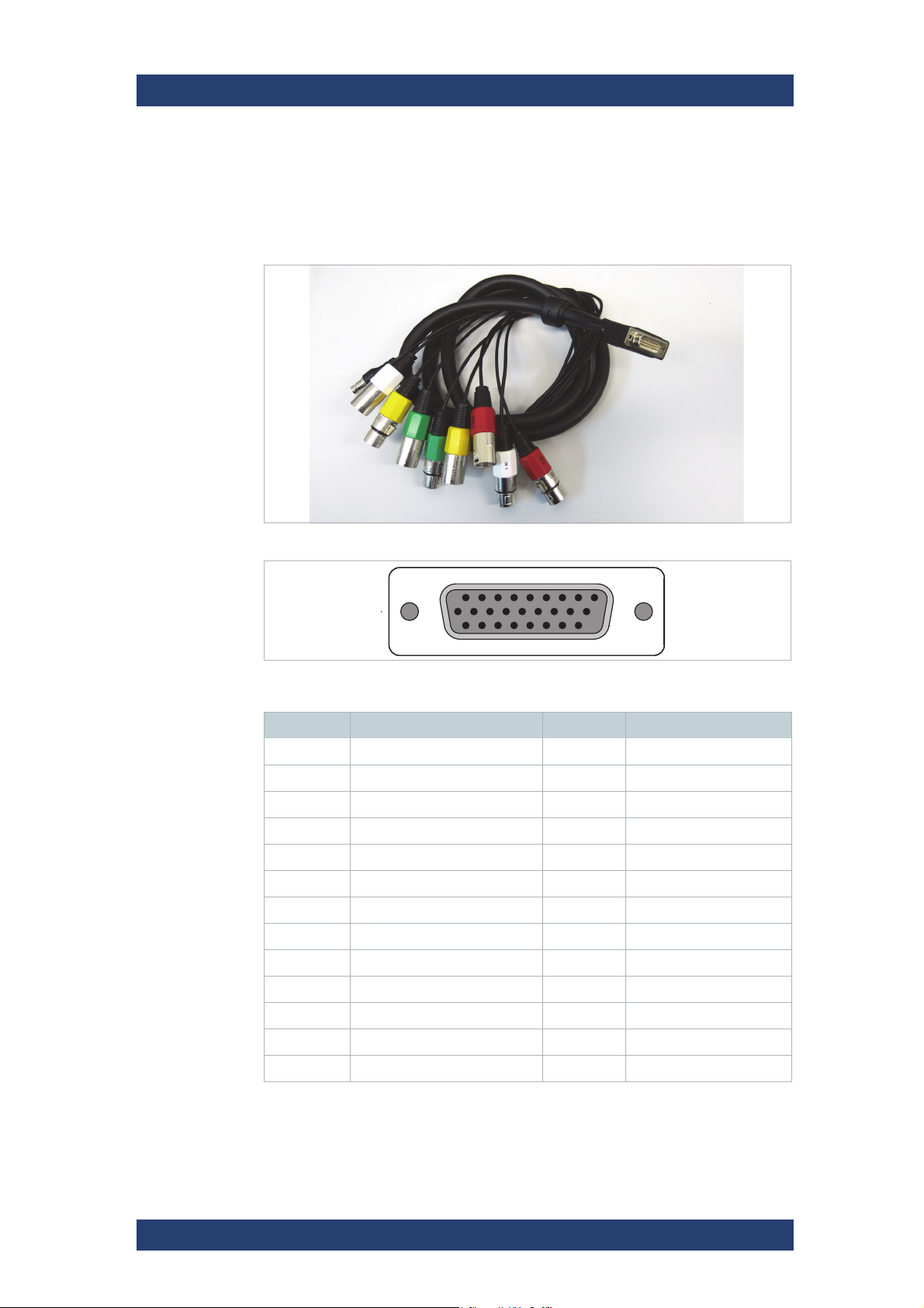
● VENICE accessory kit: 8x HD-BNC to BNC adapter cables, 4x RJ45 to
DB9-adapter cables (RS422), 1x HD-D-SUB 26 male to 8 x XLR
female/male breakout cables
Product Description
Scope of Delivery
User Manual | 2906.1145.02 - 12
29
Page 30

Product Description
12 3
4
The Front of the System
VENICE S
The Front of the System
Chassis Front
Chassis front
1 Left control panel Contains system health and system ID, status LED and optional iDRAC
Quick Sync 2 (wireless).
For more information see chapter “Left Control Panel” on page 30
2 Hard drives Up to sixteen 2.5-inch hot-swappable hard drives.
3 Right control panel Contains the power button, VGA port, iDRAC Direct micro USB port, and
two USB 2.0 ports.
For more information see chapter “Right Control Panel” on page 31
4 Information tag Contains system information such as service tag, NIC, MAC address for
your reference. The information tag is a slide-out label panel.
Left Control Panel
Control panel left
30
User Manual | 2906.1145.02 - 12
Page 31

VENICE S
Product Description
The Front of the System
1 Status LED
indicators
2 System health
and system ID
indicator
N/A Indicate the status of the system.
Right Control Panel
Control panel right
Indicates the system health. For more information,
see the System health and system ID indicator
codes section.
1 Power button Enables you to know the power status of the system.
The power indicator turns on when the system power
is on. The power button controls the power supply
output to the system.
2 USB port Enables you to connect USB devices to the system.
The ports are USB 2.0 compliant.
3 iDRAC Direct
port
4 iDRAC Direct
LED
5 Video
connector
N/A The iDRAC Direct LED indicator lights up to indicate
Enables you to connect USB devices to the system
or provides access to the iDRAC Direct features.
The USB management port is USB 2.0 compliant.
that the iDRAC Direct port is connected.
Enables you to connect a VGA display to the
system.
User Manual | 2906.1145.02 - 12
31
Page 32

Product Description
The Front of the System
Hard Drives
VENICE S
Hard drives
1 Release button
2 Hard drive carrier
3 Hard drive carrier handle
For more information about removing and installing a hard drive see chapter
“Replacing a Hot Swappable Hard Drive” on page 142.
Hard Drive Indicators
32
Hard drive indicators
User Manual | 2906.1145.02 - 12
Page 33

VENICE S
Product Description
The Front of the System
1 Hard drive activity indicator
2 Hard drive status indicator
If the hard drive is in the Advanced Host Controller Interface (AHCI)
mode, the status indicator (on the right side) does not function and
remains off.
Hard Drive Indicator Codes
Flashes green twice per
second
Off Drive ready for insertion or removal.
Identifying drive or preparing for removal.
NOTE: The drive status indicator
remains off until all hard drives are
initialized after the system is turned
on. Drives are not ready for insertion
or removal during this time.
Flashes green, amber, and
turns off
Flashes amber four times per
second
Flashes green slowly Drive rebuilding
Steady green Drive online
Flashes green for three
seconds, amber for three
seconds, and turns off after six
seconds
Predicted drive failure
Drive failed
Rebuild stopped
User Manual | 2906.1145.02 - 12
33
Page 34

Product Description
The Rear of the System
The Rear of the System
Back Panel
VENICE S
1 2 4
1213141516
35 6
11 9 7810
Back panel
1 HD Sub-D
connector
(Optional)
2 Analog audio port
(Optional)
3 HD-BNC connector N/A Reference input
4 SFP+ port (4) N/A In-/Output of digital video signals
N/A DB-26 connector (female) for a balanced audio signal in- and output of
the digital audio channels (AES/EBU); XLR connectors are available
via a breakout cable
For more information see chapter “AES/EBU Audio” on page 36. and
for the pin assignment chapter “HD Sub-D Connector (AES/EBU)” on
page 51.
N/A 3.5 mm unbalanced analog stereo headphone jack to monitor the
audio of VENICE S.
For more information see chapter “In-/Output of Digital Video Signals”
on page 40.
5 HD-BNC connector N/A Downconvert video output
For more information see chapter “Downconvert Video Output” on
page 38.
6 Full height PCIe
slot (3)
7 Power supply unit
(PSU) (2)
8 RJ45 connector,
serial RS-422 interface (4)
9 Handle N/A
10 HD Sub-D
connector
N/A Enables you to connect up to two full-height PCI Express expansion
cards.
N/A AC 1100 W
For more information see chapter “Power Supply Unit” on page 36.
N/A Out- or input of primary/secondary control signals
For more information see "Out- or Input of Primary/Secondary Control
Signals" on page 38 and for the pin assignment chapter “RJ45
Connector” on page 52.
N/A LTC In/Out
For more information see chapter “LTC In/Out” on page 35 and for the
pin assignment chapter “HD Sub-D Connector (LTC In/Out)” on
page 50.
34
User Manual | 2906.1145.02 - 12
Page 35

VENICE S
Product Description
The Rear of the System
11 Ethernet connector
(4)
Four integrated connectors that include:
● Two 10 Mbps/100 Mbps/1 Gbps NIC connectors
● Two 100 Mbps/1 Gbps/10 Gbps SFP+/10 GbE T connectors
For more information see "Network Interface Card (NIC) Connectors"
on page 44.
12 USB port (2) Enables you to connect USB devices to the system. The ports are
USB 3.0-compliant.
13 Video connector Enables you to connect a VGA display to the system. For the pin
assignment see chapter “Video Connector” on page 54.
14 Serial connector Enables you to connect a serial device to the system. For the pin
assignment see chapter “Serial Connector” on page 53.
15 iDRAC Enterprise
port
16 System identifica-
tion button
Dedicated management port.
The identification buttons on the front and back panels can be used to
locate a particular system within a rack. When one of these buttons is
pressed, the LCD panel on the front and the system status indicator
on the back flashes until one of the buttons is pressed again. Press to
toggle the system identification (ID) on or off.
LTC In/Out
HD Sub-D connector
Besides the timecode options which are described in chapter “Timecode” on
page 25 VENICE S gives you the possibility to use LTC timecode on each
channel for ingest and playout. Receive or provide LTC timecode with the
supplied Lynx cable (see chapter “Lynx CBL-AES1604 Cable” on page 56).
®
Via the R&S
Device Manager it‘s possible to assign LTC timecode that is
received by one channel to all other channels.
User Manual | 2906.1145.02 - 12
35
Page 36

Product Description
12
34
The Rear of the System
AES/EBU Audio
The optional HD Sub-D connectors can be used for a balanced audio signal
in- and output of the digital audio channels.
HD Sub-D connectors (optional)
VENICE S
HD UHD
1 Video channel 1
with audio channel 1 - 4
2 Video channel 2
with audio channel 5 - 8
3 Video channel 3
with audio channel 9 - 12
4 Video channel 4
with audio channel 13 - 16
Video channel 1 with audio channels 1 - 16
Power Supply Unit
Your system supports two 1100 W multi range PSUs (90 - 240 VAC).
36
Power supply unit
1 Release latch
2 Power supply status indicator
3 PSU
User Manual | 2906.1145.02 - 12
Page 37

VENICE S
2
Product Description
The Rear of the System
4 Power connector
5 PSU handle
For more information about removing and installing a PSU see chapter
“Replacing a Power Supply Unit” on page 140.
Power Supply Indicator
AC power supply units (PSUs) have an illuminated translucent handle that
serves as an indicator. The indicator shows whether power is present or a
power fault has occurred.
PSU status indicator
1 PSU status indicator/handle
PSU Status Indicator Codes
PSU status indicator codes
Status Condition
A Green A valid power source is connected to the PSU and the PSU is
operational.
B Flashing
green
C Flashing
green and
turns off
D Flashing
amber
When the firmware of the PSU is being updated, the PSU
handle flashes green.
When hot-adding a PSU, the PSU handle flashes green five
times at 4 Hz rate and turns off. This indicates a PSU mismatch
concerning efficiency, feature set, health status, and supported
voltage.
Indicates a problem with the PSU.
User Manual | 2906.1145.02 - 12
37
Page 38

Product Description
The Rear of the System
Out- or Input of Primary/Secondary Control Signals
RJ45 connector
During a standard operation the pin-outs of the RJ45 connector are adjusted
to secondary control mode. To use the full functionality of this connector you
have to use the supplied adapter cable. For more information about the
cable see chapter “Adapter Cable” on page 54. For the pin assignment see
chapter “RJ45 Connector” on page 52.
With software version 4 in normal operation VENICE S is in secondary
control mode. With software version 3.5 it is possible to change between
primary and secondary mode in the R&S
®
VENICE client software.
VENICE S
Downconvert Video Output
HD-BNC connector
The downconvert video output can be used for HD monitoring while the
system is configured for UHD operation. The downconvert functionality is
only active with UHD or 4K rasters. If enabled the UHD material will be send
via the SDI outputs (1 channel operation) and the HD material via the downconvert output. In principle the signal is suitable for broadcast operations
(e.g. Simulcast Playout). Please note the following restrictions.
Ingest signals (e.g. ingest of external satellite feeds), which are
asynchronously to the output can cause frame repetitions or drop
frames.
38
Compared to the UHD output the downconvert output is delayed by
a number of frames.
User Manual | 2906.1145.02 - 12
Page 39

VENICE S
Product Description
The Rear of the System
Standard Conversion
The frame rate of the downconvert output must be either the same
as the frame rate of the UHD raster or a multiple of it.
Output for 2160p50 Input:
● 576i50
1
● 720p50
● 1080p25
● 1080psf25
2
2
● 1080i50
● 1080p50
Output for 2160p59,94 Input:
● 480i59,94
1
● 720p59,94
● 1080p29,97
● 1080psf29,97
2
2
● 1080i59,94
● 1080p59,94
1
Each full p frame will be converted to a single field in alternating order. All
original motion phases will be kept during this conversion. Due to the enormous scaling factor from SD to UHD this conversion might incooperate
aliasing.
2
This conversion skips every second original frame resulting in a reduction
of temporal resolution.
User Manual | 2906.1145.02 - 12
39
Page 40

Product Description
The Rear of the System
In-/Output of Digital Video Signals
The SFP+ ports are used for an in-/output of single-link and/or quad-link SDI
video signals in 1.5G, 3G, 6G, and 12G.
To use the functionality you have to insert the dual receiver and the dual
transmitter into the SFP+ ports. For more information see chapter “Installing
the System” on page 68.
VENICE S
Use only original Rohde & Schwarz certified parts.
Channel Assignment
There are two configuration options depending on whether the system is
equipped with 12G-capable SFP modules or only 3G modules are available.
3G Configuration Option
3G SDI SFP coaxial dual transmitter
3GSDI SFP coaxial dual receiver
With the 3G configuration option all installed SFP modules are 3G-capable
only. Higher input/output modes such as 6G and 12G are also available,
however only in quad link mode.
40
User Manual | 2906.1145.02 - 12
Page 41

VENICE S
1313
2424
SDI In SDI Out
12G module 3G module
Product Description
The Rear of the System
3G Configuration
You can use any of the channels in single link mode (1.5G or 3G). For quad
link mode use 1 - 4 to form a quadrant, i.e 1.5G x 4 for 6G, or 3G x 4 for 12G.
12G Configuration Option:
12G SDI SFP coaxial dual transmitter
12GSDI SFP coaxial dual receiver
In 12G mode, every other module is 12G-capable whereas the rest of the
installed modules are still 3G:
SDI In SDI Out
1313
2424
SDI Out
14 12 14 12
13 11 1 3 11
SDI In
User Manual | 2906.1145.02 - 12
12G Configuration
41
Page 42

Product Description
The Rear of the System
The desired output mode is set in the VENICE UI software via the context
menu of the associated channel ("Video settings" > "Playout" > "Output
link").
VENICE S
In 12G configuration mode, channel 1 is reserved for 12G single
link operation. The rest of the channels can still be used in combination to form other input/output modes similar to the 3G configuration option.
42
User Manual | 2906.1145.02 - 12
Page 43

VENICE S
Product Description
The Rear of the System
Video I/O Formats
SDI 270 Mb/s Single Link
Standard Raster Framerate Cabling per channel
SMPTE 259M 525i 29.97 fps 1x SDI 1.5G
SMPTE 259M 625i 25 fps
SDI 1.5G Single Link
Standard Raster Framerate Cabling per channel
SMPTE 274M 1080i, 1080p,
1080PsF
SMPTE 296M 720p 25fps,
25 fps, 29.97
fps
29.97fps,
50fps,
59.94fps
1x SDI 1.5G
SDI 3G Single Link (Level a or B)
Standard Raster Framerate Cabling per channel
SMPTE 425 1080p 50fps, 59.94fps 1x SDI 3G
SDI 6G Single Link
Standard Raster Framerate Cabling per channel
SMPTE 2081 2160p 25fps, 29.97fps 1 x SDI 6G on 12G modules
(port 1 only)
SDI 12G Single Link
Standard Raster Framerate Cabling per channel
SMPTE 2082 2160p 50fps, 59.94fps 1 x SDI 12G (port 1 only)
User Manual | 2906.1145.02 - 12
43
Page 44

Product Description
The Rear of the System
Network Interface Card (NIC) Connectors
Ethernet connectors
1 eno1 unconfigured 10 Gbps SFP+
2 eno2 unconfigured 10 Gbps SFP+
3 eno3 DHCP 1 Gbps RJ45
4 eno4 static IP address: 10.0.0.8 1 Gbps RJ45
VENICE S
1234
Port Configuration Speed
NIC Indicator
NIC indicator
1 Link indicator
2 Activity indicator
NIC Indicator Codes
NIC indicator codes
Status Condition
2
44
A Link and activity indica-
tors are off
B Link indicator is green The NIC is connected to a valid network at its
The NIC is not connected to the network.
maximum port speed (1 Gbps or 10 Gbps).
User Manual | 2906.1145.02 - 12
Page 45

VENICE S
Product Description
The Rear of the System
C Link indicator is amber The NIC is connected to a valid network at less than
its maximum port speed.
D Activity indicator is
flashing green
Network data is being sent or received.
User Manual | 2906.1145.02 - 12
45
Page 46

Product Description
Inside the System
Inside the System
To get access to different components for example to replace a cooling fan
you have to remove the system cover.
System Cover
The system cover protects the components inside the system. Removing the
system cover actuates the intrusion switch which aids in maintaining system
security.
VENICE S
46
System cover
1 System cover
2 Latch
3 Latch release lock
For more information about opening and closing the system cover see
chapter “Removing the System Cover” on page 138 and chapter “Installing
the System Cover” on page 139.
User Manual | 2906.1145.02 - 12
Page 47

VENICE S
Product Description
Inside the System
Cooling Fan Assembly
Cooling fan assembly
1 Cooling fan assembly
2 Cooling fan (6)
3 Release lever (2)
4 Guide pin on the system board (2)
5 Cooling fan connector (6)
6 Guide pin on the chassis (6)
The cooling fan assembly is an essential part of a server’s cooling system. It
ensures that the key components of the server such as the processors, hard
drives, and memory get adequate air circulation to keep them cool. A failure
in the server’s cooling system can result in the server overheating and may
lead to damage.
For more information about removing and installing the cooling fan assembly
see chapter “Replacing a Cooling Fan Assembly” on page 144.
User Manual | 2906.1145.02 - 12
47
Page 48

Product Description
Inside the System
Cooling Fans
Your system supports six hot-swappable cooling fans.
VENICE S
Cooling fans
1 Cooling fan assembly
2 Cooling fan connector (6)
3 Fan release tab (6)
4 Cooling fan (6)
5 Cooling fan connector on the system board (6)
In the event of a problem with a particular fan, the fan number is referenced by the R&S
®
Device Manager, allowing you to easily identify and replace the proper fan by noting the fan numbers on the
cooling fan assembly.
For more information about removing and installing a cooling fan see chapter
“Replacing a Cooling Fan” on page 145.
48
User Manual | 2906.1145.02 - 12
Page 49

VENICE S
Product Description
Inside the System
Rescue Stick
Rescue stick
The VENICE contains an internal USB flash drive that can be used to restore
the operating system on the system disk back to its manufacturing state.
Further information you will find in chapter “Replacing the Internal USB
Memory Key” on page 147, chapter “Creating a Backup Image” on page 91
and chapter “Restoring the System” on page 94.
User Manual | 2906.1145.02 - 12
49
Page 50

Product Description
19
19 26
10 18
Pin Assignment
Pin Assignment
HD Sub-D Connector (LTC In/Out)
The HD Sub-D Connector enables you to use LTC In/Out. For all necessary
information see chapter “LTC In/Out” on page 35 and information about the
cable available in chapter “Lynx CBL-AES1604 Cable” on page 56.
VENICE S
HD Sub-D connector (external view on device [female])
Pin No. Signal Pin No. Signal
1 GROUND 14 OUT1 N
2 OUT4 N 15 IN4 P
3 GROUND 16 IN3 N
4 OUT2 N 17 IN2 P
5 GROUND 18 IN1 N
6 IN4 N 19 GROUND
7 GROUND 20 OUT3 P
8 IN2 N 21 GROUND
9 GROUND 22 OUT1 P
10 WORDCLOCK OUT 23 GROUND
11 OUT4 P 24 IN3 P
12 OUT3 N 25 GROUND
13 OUT2 P 26 IN1 P
50
User Manual | 2906.1145.02 - 12
Page 51

VENICE S
(a)
(b)
Product Description
Pin Assignment
HD Sub-D Connector (AES/EBU)
The HD Sub-D connector enables you to use a balanced audio signal of the
digital audio channels. For all necessary information see chapter “AES/EBU
Audio” on page 36 and information about the cable available in chapter
“Lynx CBL-AES1604 Cable” on page 56.
19 26
10 18
19
(a)
(a)
(b)
(b)
HD Sub-D connector (external view on device [female])
Pin No. Signal Pin No. Signal
1 GROUND 14 OUT1 N
2 OUT4 N 15 IN4 P
3 GROUND 16 IN3 N
4 OUT2 N 17 IN2 P
5 GROUND 18 IN1 N
6 IN4 N 19 GROUND
7 GROUND 20 OUT3 P
8 IN2 N 21 GROUND
9 GROUND 22 OUT1 P
10 WORDCLOCK IN (a) / OUT (b) 23 GROUND
11 OUT4 P 24 IN3 P
12 OUT3 N 25 GROUND
13 OUT2 P 26 IN1 P
User Manual | 2906.1145.02 - 12
51
Page 52

Product Description
81
Pin Assignment
RJ45 Connector
The RJ45 connector enables you to use Primary/Secondary control. For
more information see chapter “Out- or Input of Primary/Secondary Control
Signals” on page 38.
RJ45 connector, serial RS-422 interface (4) (external view on device
[female])
VENICE S
RJ45 Secondary Mode (default) Primary Mode
Pin No. Signal Signal
1 GND GND
2 reserved reserved
3 RX (+) TX (+)
4 TX (-) RX (-)
5 TX (+) RX (+)
6 RX (-) TX (-)
7 not connected not connected
8 not connected not connected
If you want to manufacture a direct line VDCP cable please note the
secondary mode assignment above. Your VDCP cable should connect the automation’s TX+/- pins with the RX+/- pins of the
VENICE S and vice versa (+ to + and - to - and of course
GND/ground).
52
User Manual | 2906.1145.02 - 12
Page 53

VENICE S
12345
6789
Product Description
Pin Assignment
Serial Connector
The COM port enables you to connect a serial device to the system.
R232 connector (external view on device [female])
Pin No. Signal Pin No. Signal
1 DCD 6 DSR
2 RXD 7 RTS
3 TXD 8 CTS
4 DTR 9 RI
5 Ground
User Manual | 2906.1145.02 - 12
53
Page 54

Product Description
5
10
6
1
15 11
Pin Assignment
Video Connector
The VGA port enables you to connect a VGA display to the system.
DB-15 connector (external view on device [female])
Pin No. Signal Pin No. Signal
1 RED 9 KEY
2 GREEN 10 SGND
VENICE S
3 BLUE 11 ID0
4 ID2 12 ID1 or SDA
5 GND 13 HSYNC or CSYNC
6 RGND 14 VSYNC
7 GGND 15 ID3 or SCL
8 BGND
Adapter Cable
With the adapter cable its possible to transfer the primary/secondary control
signal. For more information see chapter “RJ45 Connector” on page 52.
RS-422 (RJ-45 [RIB7.0] male to D-Sub 9
54321
18
RJ-45
9876
D-Sub 9
RS-422 (RJ45 [RIB7.0] male to D-Sub 9 female, external view)
54
User Manual | 2906.1145.02 - 12
Page 55

VENICE S
Product Description
Pin Assignment
RJ45 Secondary Mode (default) Primary Mode D-Sub 9
Pin No. Signal Signal Pin No.
1 GND GND 4, 6
2 reserved reserved 5
3 RX (+) TX (+) 3
4 TX (-) RX (-) 2
5 TX (+) RX (+) 7
6 RX (-) TX (-) 8
7, 8 not connected not connected 1, 9
User Manual | 2906.1145.02 - 12
55
Page 56
Product Description
Pin Assignment
Lynx CBL-AES1604 Cable
The Lynx CBL-AES1604 cable allows you to transfer an LTC in- and output
signal for each channel. For more information see chapter “LTC In/Out” on
page 35.
Lynx CBL-AES1604 cable
VENICE S
1
10
19
9
18
26
Lynx CBL-AES1604 cable (external view)
Pin No. Signal Pin No. Signal
1 GROUND 14 OUT1 N
2 OUT4 N 15 IN4 P
3 GROUND 16 IN3 N
4 OUT2 N 17 IN2 P
5 GROUND 18 IN1 N
6 IN4 N 19 GROUND
7 GROUND 20 OUT3 P
8 IN2 N 21 GROUND
9 GROUND 22 OUT1 P
10 WORDCLOCK OUT 23 GROUND
11 OUT4 P 24 IN3 P
12 OUT3 N 25 GROUND
13 OUT2 P 26 IN1 P
56
User Manual | 2906.1145.02 - 12
Page 57

VENICE S
Network Ports
This section lists the default TCP and UPD ports used by both the VENICE S
Server and the VENICE S Client. All ports are open by default.
The following topics are covered:
● VENICE S Server Ports (Information) (page 57)
● VENICE S Server Ports (Configuration) (page 61)
● VENICE S Client Ports (Information) (page 63)
● VENICE S Client Ports (Configuration) (page 65)
VENICE S Server Ports (Information)
Port Type Direction Info Remarks
Product Description
Network Ports
* * in & out The built-in network adapaters
for ST2110 traffic are reserved
for ST2110 only.
3702 UDP in & out WSDD service discovery udp multicast to/from ip
443 TCP in Device Manager tcp / https service listening:
8070 TCP in & out Maintenance service tcp / https service listening:
This is the dedicated
audio/video interface for
customers that want to use
video connectivity via ST2110.
239.255.255.250:
In some versions this port can
be configured in
/etc/opt/rohdeschwarz/Venice/VeniceWebService.conf as entry
WsddBroadcastPort (which is
not present by default)
Standard web server for
browser based configuration
tool "Device Manager".
If accessing via insecure port
80, users are redirectes to port
443 using secure http connection.
User Manual | 2906.1145.02 - 12
This interface controls overall
VENICE server configuration
and options
57
Page 58

Product Description
Network Ports
Port Type Direction Info Remarks
8111 – 8114,
8119
8121 - 8124,
8129
TCP in & out VDCP over IP tcp service listening:
VDCP is an industry standard
to control video tape devices.
Originally implemented over a
serial line (RS422), this implementation offers VDCP over a
socket connection. One port
per logical video channel on
the VENICE device.
VENICE S
8011 – 8014,
8019,
8021 – 8024,
8029
30001 UDP in & out SpycerNet service discovery udp multicast to/from
30002 –
40001
9983 TCP in SpycerCopy tcp service listening:
8010 TCP in Spycer web service tcp/http service listening:
TCP in VENICE web service, FIMS,
MOS
TCP in & out SpycerNet tcp service listening on port,
tcp/http service listening:
The per-channel VENICE web
services, offering control over
the video server via the MOS
and FIMS standards.
239.255.0.1:
This port is used to find other
spycer service for interoperation in the spycer network.
tcp clients connecting to other
hosts on this port:
Spycer instances communicate
using these ports, starting from
30002.
dedicated port used to transfer
files.
Spycer offers its operations to
automations / spycer client.
161
162
8093 TCP in Workflow engine tcp/http service listening:
58
UDP in
out
SNMP and
SNMP Traps
udp listening on ports
udp sending to ports
snmp communication. SNMP
is a protocol to monitor
network activity.
The workflow engine can be
configured and controlled by
REST requests to this port.
User Manual | 2906.1145.02 - 12
Page 59

VENICE S
Product Description
Network Ports
Port Type Direction Info Remarks
4224 TCP in & out Virtual Storage Access (VSA) tcp service listening and
connecting to other tcp
services on this port.
4225 UDP in & out Virtual Storage Access (VSA) udp multicast service liste-
neing
80, 443 TCP in iDRAC
25, 587 TCP out E-mail notifications E-mail notifications from RuS
123 UDP out (& in) NTP Listening on udp port for client
DELL m
name "root" and the serial
number of the system as
pass-word to log in. For
systems built after April 2022
prepend "rs" to the begin-ning
of the serial number (e.g
"rs123456").
software
requests
anagement. Use user-
sending on other servers' udp
port to fetch and negotiate
current time.
depending on config
53 UDP/TCP out DNS tcp/udp / DNS
asking other name servers to
resolve host names.
22 TCP in SSH tcp / ssl
Offering secure command line
remote access.
137, 138, 139,
445
TCP in & out SMB tcp listening:
Offering windows network
shares
tcp connecting to other
servers:
Accessing windows network
shares hosted on different
machines.
User Manual | 2906.1145.02 - 12
59
Page 60

Product Description
Network Ports
Port Type Direction Info Remarks
20, 21 TCP in & out FTP tcp listening on 21:
Offering ftp (file transfer)
service and passive ftp
transfer.
tcp connecting FROM port 20
to random client port as offered
by client: active ftp transfer (as
legacy mode of operation).
VENICE S
2049, 111 UDP/TCP in & out NFS (Other ports might be
required, too)
5960 - 5970 TCP in VENICE Video overlay
streaming
5353 UDP in & out VENICE NDI: Service
discovery
4711 - 4714,
4719
4721 - 4724,
4729
5960 TCP in VENICE NDI: General commu-
5961 - 5970 TCP in NDI: Communication
TCP in VENICE NDI: Overlay
streaming
nication
One port per overlay channel
(in random order, so channel 1
is not always on 5961)
tcp and/or udp server listening
and / or
connecting to other server.
Actual port usage highly
depends on actual configuration on client-side.
Multicast, mDNS
tcp service listeneing:
Stream catalogue of NDI
streams
depending on configuration:
when using TCP:
tcp service listening: One port
per overlay channel (in random
order, so channel 1 is not
always on 5961)
when using UDP: udp service
listening and pushing packets
from this port.
6960 - 6969 TCP/UDP in & out VENICE NDI: Video Streaming depending on configuration:
Receiving NDI data.
7960 - 7969 TCP/UDP in & out VENICE NDI: Video streaming depending on configuration:
Sending NDI data.
60
User Manual | 2906.1145.02 - 12
Page 61

VENICE S
Product Description
Network Ports
Port Type Direction Info Remarks
8031 TCP in RuS Installation service (RSI) tcp service listeneing:
Receiving orders to install an
RSI.
13217 TCP/UDP in & out RuS Installation service (RSI)
VENICE S Server Ports (Configuration)
Port NIC Multicast Protocol Configurable Config recom-
mended
* ST2110
NIC names
dynamically
3702 primary
(eno3)
239.255.255.250 http, XML no
ST2110 no
443 primary
(eno3)
8070 primary
(eno3)
8111 – 8114,
8119
8121 - 8124,
8129
8011 – 8014,
8019,
8021 – 8024,
8029
30001 primary
30002 –
40001
9983 primary
8010 primary
161
162
8093 primary
primary
(eno3)
primary
(eno3)
(eno3)
primary
(eno3)
(eno3)
(eno3)
primary
(eno3)
(eno3)
Spycer Multicast
IP (239.255.0.1)
https no
http,
SOAP
VDCP
binary
http,
SOAP
proprietary,
encrypted
proprietary,
encrypted
binary no
http,
SOAP
http,
REST
no
no
no
/etc/opt/rohdeschwarz/Spycer/IP.c
onf
/etc/opt/rohdeschwarz/Spycer/IP.c
onf
no
no
No, not a uservisible feature
No, not a uservisible feature
User Manual | 2906.1145.02 - 12
61
Page 62

Product Description
VENICE S
Network Ports
Port NIC Multicast Protocol Configurable Config recom-
mended
4224 /etc/opt/rohde-
schwarz/BfsSyncD/b
fs-syncd.conf
and/or
/etc/opt/rohdeschwarz/Bfs/bfs.conf
4225 VSA multicast IP
239.192.42.23
80, 443 iDRAC
socket
25, 587 primary
(eno3)
123 primary
(eno3)
53 primary
(eno3)
22 primary
(eno3)
137, 138, 139,
445
20, 21 primary
primary
(eno3)
(eno3)
http,
(https)
smtp,
smtps
NTP /etc/ntp.conf No, not a user-
DNS no
SSH /etc/sshd/sshd.conf No, not a user-
SMB no
FTP /etc/vsftpd/ No, not a user-
/etc/opt/rohdeschwarz/BfsSyncD/b
fs-syncd.conf
and/or
/etc/opt/rohdeschwarz/Bfs/bfs.conf
No, not a uservisible feature.
No, not a uservisible feature.
visible feature
visible feature
visible feature
2049, 111 primary
(eno3)
5960 - 5970 primary
(eno3)
5353 primary
(eno3)
4711 - 4714,
4719
4721 - 4724,
4729
5960 primary
5961 - 5970 primary
6960 - 6969 primary
7960 - 7969 primary
primary
(eno3)
(eno3)
(eno3)
(eno3)
(eno3)
NDI no Configuration not
possible by user
224.0.0.251 mDNS no Configuration not
possible by user
NDI no Configuration not
possible by user
NDI no Configuration not
possible by user
NDI no Configuration not
possible by user
NDI no Configuration not
possible by user
NDI no Configuration not
possible by user
62
User Manual | 2906.1145.02 - 12
Page 63

VENICE S
Product Description
Network Ports
Port NIC Multicast Protocol Configurable Config recom-
mended
8031 primary
(eno3)
13217 primary
(eno3)
http no
proprietary
no
VENICE S Client Ports (Information)
Port Type Direction Info Remarks
3702 UDP out WSDD service discovery udp multicast to/from ip
239.255.255.250:
443 TCP out Device Manager using VENICE tcp / https
service:
Accessing standard web
server for browser based
configuration tool "Device
Manager".
If accessing via insecure port
80, users are redirectes to port
443 using secure http connection.
8070 UDP in Maintenance service using VENICE tcp / https
service:
This interface controls overall
VENICE server configuration
and options.
8011 – 8014,
8019,
8021 – 8024,
8029
30001 UDP in & out SpycerNet service discovery udp multicast to/from
TCP in VENICE web service, FIMS,
MOS
using VENICE tcp/http service:
The per-channel VENICE web
services, offering control over
the video server via the MOS
and FIMS standards.
239.255.0.1:
This port is used to find other
spycer service for interoperation in the spycer network.
User Manual | 2906.1145.02 - 12
63
Page 64

Product Description
VENICE S
Network Ports
Port Type Direction Info Remarks
30002 40001
9983 TCP in Spycer copy tcp service listening:
8010 TCP in Spycer web service tcp/http service listening:
8093 TCP in Workflow engine using VENICE tcp/http service:
5960 - 5970 TCP in VENICE Video overlay
TCP in SpycerNet tcp service listening on port,
tcp clients connecting to other
hosts on this port:
Spycer instances communicate
using these ports, starting from
30002.
dedicated port used to transfer
files.
Spycer offers its operations to
automations / spycer client.
The workflow engine can be
configured and controlled by
REST requests to this port.
streaming
5353 UDP in & out VENICE NDI: Service
discovery
4711 - 4714,
4719
4721 - 4724,
4729
5960 TCP in VENICE NDI: General commu-
5961 - 5970 TCP in VENICE NDI: Communication depending on configuration:
6960 - 6969 TCP/UDP in & out VENICE NDI: Video streaming depending on configuration:
TCP in VENICE NDI: Overlay
streaming
nication
Multicast, mDNS
tcp service listeneing:
Stream catalogue of NDI
streams
when using TCP:
tcp service listening: One port
per overlay channel (in random
order, so channel 1 is not
always on 5961)
when using UDP: udp service
listening and pushing packets
from this port.
Receiving NDI data.
64
User Manual | 2906.1145.02 - 12
Page 65

VENICE S
Product Description
Network Ports
Port Type Direction Info Remarks
7960 - 7969 TCP/UDP in & out VENICE NDI: Video streaming depending on configuration:
Sending NDI data.
8031 TCP out RuS Installation service (RSI) using VENICE tcp service:
Sending orders to install an
RSI.
13217 TCP/UDP in & out RuS Installation service (RSI)
VENICE S Client Ports (Configuration)
Port NIC Multicast Protocol Configurable Config recom-
mended
3702 primary
(eno3)
239.255.255.250 http, XML no
443 primary
(eno3)
8070 primary
(eno3)
8011 – 8014,
8019,
8021 – 8024,
8029
30001 primary
30002 40001
9983 primary
8010 primary
8093 primary
5960 - 5970 primary
5353 primary
4711 - 4714,
4719
4721 - 4724,
4729
primary
(eno3)
(eno3)
primary
(eno3)
(eno3)
(eno3)
(eno3)
(eno3)
(eno3)
primary
(eno3)
https no
http,
SOAP
http,
SOAP
Spycer Multicast
IP (239.255.0.1)
224.0.0.251 mDNS no Configuration not
proprietary,
encrypted
proprietary,
encrypted
binary no
http,
SOAP
http,
REST
NDI no Configuration not
NDI no Configuration not
no
no
/etc/opt/rohdeschwarz/Spycer/IP.c
onf
/etc/opt/rohdeschwarz/Spycer/IP.c
onf
no
no
No, not a uservisible feature
No, not a uservisible feature
possible by user
possible by user
possible by user
User Manual | 2906.1145.02 - 12
65
Page 66

Product Description
VENICE S
Network Ports
Port NIC Multicast Protocol Configurable Config recom-
mended
5960 primary
(eno3)
5961 - 5970 primary
(eno3)
6960 - 6969 primary
(eno3)
7960 - 7969 primary
(eno3)
8031 primary
(eno3)
13217 primary
(eno3)
NDI no Configuration not
possible by user
NDI no Configuration not
possible by user
NDI no Configuration not
possible by user
NDI no Configuration not
possible by user
http no
proprietary
no
66
User Manual | 2906.1145.02 - 12
Page 67

Installation and ConfigurationVENICE S
Installation and Configuration
This chapter is divided into the following sections:
● "Installing the System" (page 68)
● "Starting the System" (page 72)
● "Configuring the System" (page 73)
● "Shutting Down the System" (page 75)
User Manual | 2906.1145.02 - 12
67
Page 68

Installation and Configuration
Installing the System
Installing the System
Perform the following steps:
1.
Unpack the VENICE S system and its accessories.
Warranty Claims
To make warranty claims you have to keep the original
packing and use it in case of a return transportation.
2. Check your delivery and compare it with the delivery note. In case of
missing items, contact your local vendor or Rohde & Schwarz immediately.
VENICE S
Risk of Injury
Improper handling of the VENICE S can cause
substantial damage to personnel and equipment by
falling or overturning
● VENICE S must be lifted and carried by two
people on both sides
● It is preferable to use lifting devices and means
of transport
● Beware of the crushing hazard when working
with heavy loads
3. Place the system on a firm, flat surface within reach of a power outlet or
mount it in a rack. For proper air circulation and cooling make sure the
ventilation holes on the rear of the system are not covered.
68
User Manual | 2906.1145.02 - 12
Page 69
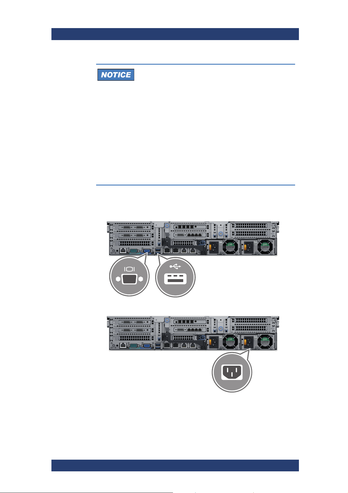
VENICE S
Installation and Configuration
Environmental Conditions
For error-free working and a long service life VENICE S
needs some basic environmental conditions:
● Do not expose VENICE S to sources of heat, such as
direct sunlight or a radiator.
● Do not cover or obstruct the ventilation holes of the
system. When installing the system in a rack, take care
that warmed up air is conducted to the rear of the rack
and properly vented away.
● Avoid areas with high humidity or dust. Best operating
conditions are given in an air-conditioned site.
● Do not expose VENICE S to strong electric or magnetic
fields.
● Avoid areas where VENICE S will be subject to vibra-
tions or shocks.
If necessary connect the following computer peripherals:
4.
Mouse
Keyboard
Monitor
Installing the System
5. Connect the system to a power source.
User Manual | 2906.1145.02 - 12
69
Page 70

Installation and Configuration
Installing the System
Data Loss/Corrupt Data
In the event of a power failure the device will be abruptly switched off. This
can result in corrupt data, loss of data, and equipment damage.
Connect the system to an uninterruptible power supply (UPS) redundantly on two phases.
Loop and secure the power cable using the retention strap.
6.
VENICE S
7. Connect a network cable to the Ethernet connector “eno3”.
The IP address is assigned automatically.
8. Connect a network cable to the Ethernet connector “eno4”.
The default IP is 10.0.0.8.
Use only original Rohde & Schwarz certified parts.
2
70
User Manual | 2906.1145.02 - 12
Page 71

VENICE S
1313
2424
SDI In SDI Out
14 12 14 12
13 11 13 11
SDI Out
SDI In
Installation and Configuration
Installing the System
9.
Insert the supplied SDI SFP coaxial dual transmitter (arrows point
outwards) and the SDI SFP coaxial dual receiver (arrows point inwards)
into the according SFP+ ports.
In case you are installing the 12G option, consult also section
"Channel Assignment" on page 40 for the correct position of the
SFP modules.
10. Connect the HD-BNC to BNC adapter cables to the SDI In/Out connec-
tors.
11. Connect any other peripheral computer and video equipment. An over-
view of the panels and connectors are listed in chapter “The Rear of the
System” on page 34.
VENICE S is ready for first use.The VENICE S hardware is now properly
installed and you can switch on the system.
User Manual | 2906.1145.02 - 12
71
Page 72

Installation and Configuration
Starting the System
Starting the System
After a proper installation of the system you may start the VENICE S system
at any time.
Perform the following steps:
• Press the power switch briefly to turn on the system.
The system will be started. It takes several minutes until the system is
fully operational.
VENICE S
For the initial setup the device must be integrated into a network. If the IP of
the device is already known a remote SSH terminal (e.g. Putty) can be used
to make the basic configuration. Alternatively a monitor and keyboard can be
temporarily connected on the front or on the rear of the system. Continue
with chapter “Configuring the System” on page 73.
72
User Manual | 2906.1145.02 - 12
Page 73

VENICE S
Configuring the System
For the initial setup the device must be integrated into a network.
Log In
Perform the following steps:
• Log in as root with the following password: [serial number of the
device].
Network Configuration
There are two ways for the network configuration. You can use a dynamic or
a static IP address as described bellow.
Dynamic IP
Installation and Configuration
Configuring the System
Perform the following steps:
• Determine the dynamic IP with the command:
ifconfig eno3
Static IP
Perform the following steps:
1. Edit the configuration file with:
vi /etc/sysconfig/network-scripts/ifcfg-eno4
2. Change line IPADDR=10.0.0.8 into: IPADDR= your new IP address
3. Activate the new IP with:
systemctl restart network
Integrating Software Service
This setting configures which network interface the software uses for
communication. In general this setting is already configured to use the interface eno3. Only use the following steps if a different configuration is necessary.
Perform the following steps:
• Use the command fbms-setup -c [interface] to integrate the soft-
ware services on the network.
e.g.: fbms-setup -c eno4
After the command is executed the configuration is complete. VENICE S can
immediately be operated by remote control from any Windows system
connected to the same network.
User Manual | 2906.1145.02 - 12
73
Page 74

Installation and Configuration
Configuring the System
System Update
Follow the steps in chapter “System Update” on page 97.
VENICE S
74
User Manual | 2906.1145.02 - 12
Page 75

VENICE S
Shutting Down the System
There are several possibilities to shut down the system. It depends on
whether the operating system is already loaded, frozen or not completely
loaded. Please act accordingly.
Re-start
It takes a while to safely erase all memory banks of the
system.
After a shut-down wait at least ten seconds before starting
the system again.
Shut Down While Running
Perform the following steps:
• Enter poweroff in the command line of the VENICE S.
The operating system will save your personal settings and once it has
ended, the system will turn off.
Installation and Configuration
Shutting Down the System
System is shut down.
Shut Down With Operating System Frozen or Not Completely Loaded
If the operating system is not responding anymore or not completely loaded,
do as follows:
Corrupted Data
Shutting down the system while frozen or not completely
loaded may lead to corrupted system data.
Use this procedure only if absolutely necessary.
Perform the following steps:
• Shut down the system by pressing the power switch lengthly until the
system turns off.
The system is shut down.
User Manual | 2906.1145.02 - 12
75
Page 76

Installation and Configuration
Shutting Down the System
VENICE S
76
User Manual | 2906.1145.02 - 12
Page 77

Operation
This chapter includes the following section:
● Operating the System
OperationVENICE S
User Manual | 2906.1145.02 - 12
77
Page 78

Operation
Operating the System
Operating the System
This section describes how to operate VENICE S.
The following topics are covered:
● "Usable Software and Protocols" (page 78)
● "VENICE UI" (page 78)
● "Playing Content" (page 79)
● "Ingesting Content" (page 79)
● "Transforming Content" (page 80)
● "File Management" (page 80)
● "Configuring VENICE S Services" (page 81)
● "Configuring the Subtitles" (page 84)
Usable Software and Protocols
VENICE S
Module Software / Protocol
Ingest VDCP RS-422, TCP/IP
R&S®VENICE UI
FIMS capture SOAP
Playout VDCP RS-422, TCP/IP
R&S®VENICE UI
MOS SOAP
Transform R&S®VENICE UI
FIMS transform SOAP
VENICE UI
The R&S®VENICE UI software is the operator’s interface to the video channels. With it the operator can connect to the server (i.e. to the VENICE
server software) via network and allocate one of the video channels to
control ingest, playout and transform operations. The R&S
ware can be installed on any Windows network client for a remote control of
the server. With one instance of the software you can control different video
channels of one or more VENICE servers at the same time.
®
VENICE UI soft-
78
User Manual | 2906.1145.02 - 12
Page 79

VENICE S
Operation
Operating the System
Playing Content
The R&S®VENICE UI Playout Module is the operator‘s interface to the video
channels to play content. With one instance of the software you can control
different video channels of one or more VENICE servers at the same time.
In addition VENICE S supports MOS 3.8.4 using SOAP. By implementing
MOS, Rohde & Schwarz has opened and simplified the integration of the
VENICE S.
Furthermore VENICE S with software is VDCP compliant. This proprietary
communications protocol primarily is used in broadcast automation to control
broadcast devices, like video servers for broadcast television. The serial
communications protocol based on RS-422 is derived from the Sony 9-Pin
protocol, an industry-standard protocol for controlling professional broadcast
VTRs.
VENICE S uses the tightly coupled primary-secondary methodology of
VDCP. The controlling device takes the initiative in communications between
the controlling broadcast automation device and the controlled device (video
disk). VDCP conforms to the Open Systems Interconnection (OSI) reference
model.
For more information see chapter “Configuring VENICE S Services” on
page 81 and chapter “Out- or Input of Primary/Secondary Control Signals”
on page 38.
Ingesting Content
With R&S®VENICE UI you can connect to the server via network and control
single and multi channel ingest operations. With one instance of the software
you can control different video channels of one or more VENICE servers at
the same time.
Furthermore VENICE S supports FIMS capture using SOAP. Rohde &
Schwarz has chosen to implement the FIMS protocol as the primary method
by which machines may access their devices and consume their services.
For more information see chapter “Configuring VENICE S Services” on
page 81.
User Manual | 2906.1145.02 - 12
79
Page 80

Operation
Operating the System
Transforming Content
With R&S®VENICE UI it is possible to control transform jobs and you can
use FIMS as well. For more information see chapter “Configuring VENICE S
Services” on page 81.
File Management
The innovative data and content control software R&S®Spycer allows you to
easily maintain transparency and control over video and audio data and their
associated metadata. The software offers conclusive rights management,
browsing, searching and viewing of video and audio material.
Rohde & Schwarz offers the Spycer functionality also via Spycer web
service. For more information see chapter “Configuring VENICE S Services”
on page 81.
VENICE S
80
User Manual | 2906.1145.02 - 12
Page 81

VENICE S
Operation
Operating the System
Configuring VENICE S Services
To use one of the mentioned methods on a VENICE S with you have to activate the respective function in the R&S
tion about the different web services, VDCP as well as how to integrate and
control VENICE S by third-party software see the Software Integration
Guide. (available at https://gloris.rohde-schwarz.com)
Activating and Launching VDCP
Perform the following steps:
1.
Open the R&S®Device Manager on your local system. To get access to
the R&S
IP address and the port 3000 in a standard browser.
2. Select the VENICE MEDIA SERVER tab.
®
Device Manager you have to enter the previously determined
®
Device Manager. For more informa-
The running mode will be indicated in the respective tile in the system
view.
3. Select the respective system.
User Manual | 2906.1145.02 - 12
81
Page 82

Operation
Operating the System
4.
5. Click Disconnect to make the channel available for the VDCP mode.
VENICE S
If the system runs in another mode than VDCP select the running mode
(e.g. FIMS).
6. Select the VDCP mode in the Automation Control settings.
7. Enter a valid Path to a local or a central storage for each channel.
8. Activate InitiallyLocked for each channel.
9. Click Connect to start the VDCP mode of the respective channel.
A successfully started connection of a channel in VDCP mode will be indicated in the system view.
82
User Manual | 2906.1145.02 - 12
Page 83

VENICE S
Operation
Operating the System
Video Settings
Perform the following steps:
1.
Select the Sync Reference settings in the Video Settings.
2. Set the Sync Mode, the syncHPhase and the syncVPhase as
needed. For detailed information see the documentation of the
®
R&S
Device Manager.
3. Select the HD/UHD settings in the Video Settings.
User Manual | 2906.1145.02 - 12
83
Page 84

Operation
Operating the System
4.
Configuring the Subtitles
VENICE S
Set the Mode as needed. For detailed information see the documentation of the R&S
®
Device Manager.
This section describes the configuration of subtitles for the VENICE S
®
system using the R&S
Device Manager.
The following topics are covered:
● Subtitle Configuration in Device Manager (page 84)
● VDCP Subtitle Parameters (page 86)
Subtitle Configuration in Device Manager
To access the subtitle configuration settings in Device Manager, select the
associated system within the Workspace and navigate to "Video Settings" >
"Record" > "Subtitle Configuration".
84
Subtitle Configuration
User Manual | 2906.1145.02 - 12
Page 85

VENICE S
Operation
Operating the System
Record Subtitle
Type
SCC Start From
Mode
Determines whether subtitle recording is enabled or not (Off)
and which type of subtitles (Scc1, Scc3 or Stl) should be
recorded.
Specifies the start mode determination method for SCC:
● StartZero: Read/Write: SCC files always start at 0.
● ParentTC: Read/Write: SCC files derive the starting point
from the first video TC.
● Guess: Read: Try to guess whether the SCC file starts
with 0 or with the video TC. Write: Same as ParentTC.
● UserDefined: Read/Write: The start is user-defined.
SCC Drop Frame Specifies the dropframe-mode determination method for SCC.
● Auto: SCC files dropframe-mode is determined by the
video stream.
● NoneDropFrame: SCC files are always non-dropframe.
● DropFrame: SCC files are always dropframe.
Start Frame
Number
Start Timecode STL: Defines the video program start timecode. Only one of
STL Subtitle Page
Number
STL GSI Code
Page Number
Determines the frame number of the first video frame calculated from the start time code for SCC and STL.
startFrameNumber and startTimeCode may be present.
Determines the subtitle page number for STL. Enter a value in
the following range: 100-899.
Determines a character code page for the STL GSI block
(UnitedStates, Multilingual, Portugal, Canada-French, Nordic).
stlDisplayStandardCode
stlLanguageCode Determines the language code for STL. Allowed values are:
Determines the display code for STL (OpenSubtitling, Level1,
Level2).
● 04 (Croatian)
● 06 (Czech)
● 08 (German)
● 09 (English)
● 0A (Spanish)
● 0C (Estonian)
● 0F (French)
● 15 (Italian)
● 1A (Lithuanian)
● 1B (Hungarian)
● 20 (Polish)
● 21 (Portuguese)
● 22 (Romanian)
● 24 (Serbian)
● 25 (Slovak)
● 26 (Slovenian)
● 27 (Finnish)
● 28 (Swedish)
● 29 (Turkish
User Manual | 2906.1145.02 - 12
85
Page 86

Operation
Operating the System
VDCP Subtitle Parameters
In this dialog you can globally set the directory in which the VENICE S
system will look for subtitle files. To access the VDCP Parameters in Device
Manager, navigate to "Automation control" > "VDCP Parameters".
VENICE S
VDCP Subtitle Parameters
Subtitle File Path Determines the directory where the system looks for subtitle
files when 'SubtitleMode' is enabled. If this option is omitted or
an empty string is given, the VDCP root directory is used.
Subtitle Mode Determines whether the system automatically uses subtitle
files, if available.
● Off: No subtitle files are used.
● Auto: If a supported subtitle file for the clip is present, it will
be automatically used.
86
User Manual | 2906.1145.02 - 12
Page 87

Administration
This chapter is divided into the following sections:
● "User Management" (page 88)
● "Creating a Backup Image" (page 91)
● "Restoring the System" (page 94)
● "System Update" (page 97)
● "SNMP System Monitoring" (page 98)
● "Integration into an IP Network" (page 111)
AdministrationVENICE S
User Manual | 2906.1145.02 - 12
87
Page 88

Administration
User Management
User Management
To integrate VENICE S into an existing environment it is necessary to be
able to change the user permissions.
To achieve this, observe the following:
● Changing the Passwords (page 88)
● Changing the User ID (page 89)
● Adding Samba Users (page 90)
The steps below are valid for VENICE S with software 3.5 or higher.
Changing the Passwords
To ensure the safety of systems connected in a network and/or to the
Internet, we highly recommend to change the default password on both the
VENICE S server as well as the on the web UI interface of
R&S®Device Manager as soon as the initial setup is completed.
VENICE S
Changing the server password
Perform the following steps:
1.
Log in to the server as root user either directly or via SSH using the
default/existing password. The root user is the account that has full
access to all files, applications, and system functions.
2. At the prompt, type "passwd root" and press "Enter":
3. The system will prompt you to enter the current password. Do so, then
follow the prompts to define and confirm a new root password.
The password change takes effect immediately.
88
User Manual | 2906.1145.02 - 12
Page 89

VENICE S
Administration
User Management
Changing the R&S®Device Manager password
Perform the following steps:
1.
Open the R&S®Device Manager on the current system.
2. Navigate to "User administration"
3. Select the respective user and then select "Change password".
The "Change password" window opens.
4. Enter the new password and confirm with "OK".
The password of the web UI is now set.
Changing the User ID
All the R&S software on a VENICE S runs as user “rsapp”, who is in the
group “rsapp”. By default user rsapp has the user ID (UID) 1000 and the
rsapp group has group ID (GID) 1000. The steps below describes how to
change that.
Perform the following steps:
1. Ensure that the system is currently not used.
2. Log into the system as root, either directly or via SSH.
3. Stop all R&S processes with:
/opt/rohde-schwarz/fbms-services.sh stop
4. Query the UID that is currently used by user rsapp with:
id -u rsapp (By default this should be 1000.)
5. Query the UID that is currently used by group rsapp with:
id -g rsapp (By default this should be 1000.)
6. Modify the UID (e.g. to 1234): usermod -u 1234 rsapp
If there are still processes running as rsapp, usermod will show an
error message like this:
usermod: user rsapp is currently used by process 4224
7. Stop the running processes if necessary.
8. Modify the GID (e.g. to 1234): groupmod -g 1234 rsapp
User Manual | 2906.1145.02 - 12
89
Page 90

Administration
User Management
VENICE S
Change the ownership of files that belonged to user rsapp, so they
9.
belong to that user again:
find / -mount -user 1000 -exec chown -h rsapp {} \;
1000 is the UID that you query in step 4.
This only changes the files on the system disk (/). You can run this for
your storage too, if needed.
10. Change the group affiliation of files that belonged to group rsapp, so they
belong to that group again:
find / -mount -group 1000 -exec chgrp -h rsapp {} \;
1000 is the GID that you query in step 4.
Due to the -mount option find will only change files on the system
disk. You can run this for your storage too, if needed.
Adding Samba Users
Perform the following steps:
1. Decide about the name and password for the new account and which
group the user should be in. It might be advisable to use the rsapp
group, so the user can read clips written by VENICE. The default GID of
the rsapp group is 1000.
In this example we will use the name “username” and the GID “1000”.
2. Add the account:
useradd username -g 1000 -N -s /sbin/nologin
3. Set a password for that user:
smbpasswd -a username
You will be prompted for a password.
90
User Manual | 2906.1145.02 - 12
Page 91

VENICE S
Creating a Backup Image
The following describes the steps to make a backup image of the system
disk and save it to the internal USB flash drive.
Perform the following steps:
If appropriate, disconnect all externally connected storage devices from
1.
the system.
2. Turn on the VENICE S. At the indicated moment during start-up you
have to press [F11] to enter the boot menu.
The boot menu is displayed on the screen.
3. Select the internally installed USB flash drive as the boot device.
Administration
Creating a Backup Image
4. Press [Enter].
The system will boot from the internal USB flash drive.
You will see a window on the screen where you can select the Rohde
& Schwarz Rescue environment for loading.
To complete the loading of the Rohde & Schwarz Rescue environment some user entries are required. For this follow the instructions
given on the screen.
The loading of the environment and the process itself will both try to
initialize hardware that may not be present on your system. Any error messages displayed during loading/initialization, e.g. Failed or
Warning, can be disregarded. The backup/recovery process
should work nonetheless.
5. Select RuS Rescue and press [Enter].
User Manual | 2906.1145.02 - 12
91
Page 92

Administration
--- RuS Rescue ---
1 - Backup on internal USB device
2 - Restore from internal USB device
5 - Reboot the system
6 - Poweroff the system
0 - Exit
Enter selection:
3 - Backup on self selected external device
4 - Restore from self selected external device
Creating a Backup Image
Once the loading has finished, you will see the RuS Rescue script
VENICE S
If you do not perform any action, RuS Rescue will be
loaded automatically after 30 seconds.
with its options on the screen. Your display should look similar to the
following:
6. To create a backup image of your system disk and save it to the internal
USB flash drive, press [1] and then [Enter].
A list of possible source devices will be detailed on the screen. The
system disk normally is the ‘ATA’ disk with, for example, ‘sda’, ‘sdb’ or
‘sdc’ as its device name
(e.g.:
1:0:0:0 disk ATA <device info> /dev/sda).
Ex factory the VENICE S will be delivered with ’sda’ as the
default system disk. If other configurations have been made
later or on customer request, this may be different.
Data Loss
Selecting the wrong source device may lead to an
unwanted configuration and malfunctions when the system
is operating.
Continue with the following steps only if you are able to
identify the correct source device.
7. Enter the name of the system disk: Type in e.g. sda (or in other cases
sdb, sdc, etc.) and press [Enter].
The system will ask you to enter the image name for the backup
image to be saved to the USB flash drive. By entering the name of an
already existing backup image you can overwrite it.
92
8. Type in the name of the image you want to save to the USB flash drive
for a later recovery. To confirm your entry press [Enter].
The system will ask you to confirm your selection and whether you
want to continue:
User Manual | 2906.1145.02 - 12
Page 93

VENICE S
Administration
Creating a Backup Image
To abort the process at this point enter n for ‘no’ and press [Enter].
You will be redirected to the RuS Rescue script.
After starting the process its termination is no longer possible.
9.
To start the backup process type in y for ‘yes’ and press [Enter].
The program starts the backup process. Its progress will be indicated
on the screen.
The backup process may take some time.
If during the process the screen turns black, press [Space] to get it
back again.
When the system has finished the backup process, you will be notified about
this. Then after pressing [Enter], you will be redirected to the Rohde &
Schwarz Rescue script once more where you can choose, for example,
‘reboot’ or ‘poweroff’ to restart or turn off the system.
User Manual | 2906.1145.02 - 12
93
Page 94

Administration
Restoring the System
Restoring the System
The following describes the steps to make a recovery of the system disk.
Total Loss of Data
Selecting the wrong device for restoring the system partition
will lead to a total loss of data.
Do not execute any commands if you are not sure about
the correct target device.
Perform the following steps:
1.
If appropriate, disconnect all externally connected storage devices from
the system.
2. Turn on the VENICE S. At the indicated moment during start-up you
have to press [F11] to enter the boot menu.
The boot menu is displayed on the screen.
3. Select the internally installed USB flash drive as the boot device.
VENICE S
4. Press [Enter].
The system will boot from the internal USB flash drive. You will see a
window on the screen where you can select the Rohde & Schwarz
Rescue environment for loading.
To complete the loading of the Rohde & Schwarz Rescue environment some user entries are required. For this follow the instructions
given on the screen.
The loading of the environment and the process itself will both try to
initialize hardware that may not be present on your system. Any error messages displayed during loading/initialization, e.g. Failed or
Warning, can be disregarded. The backup/recovery process
should work nonetheless.
5. Select RuS Rescue and press [Enter].
94
User Manual | 2906.1145.02 - 12
Page 95

VENICE S
--- RuS Rescue ---
1 - Backup on internal USB device
2 - Restore from internal USB device
5 - Reboot the system
6 - Poweroff the system
0 - Exit
Enter selection:
3 - Backup on self selected external device
4 - Restore from self selected external device
Administration
Restoring the System
If you do not perform any action, RuS Rescue will be
loaded automatically after 30 seconds.
Once the loading has finished, you will see the Rohde & Schwarz
Rescue script with its options on the screen. Your display should look
similar to the following:
6. To restore your system disk from the internal USB flash drive, press [2]
and then [Enter].
A list of possible target devices will be detailed on the screen. The
system disk normally is the ’ATA’ disk with, for example, ’sda’, ’sdb’ or
’sdc’ as its device name:
(e.g.:
1:0:0:0 disk ATA <device info> /dev/sda).
Ex factory the VENICE S will be delivered with ’sda’ as the
default system disk. If other configurations have been made
later or on customer request, this may be different.
Data Loss
A recovery will overwrite all your data.
Continue with the following steps only when you are
able to identify the correct target device.
7. Enter the name of the system disk: Type in e.g. sda (or in other cases
sdb, sdc, etc.) and press [Enter].
A further list of possible source images will be detailed on the screen.
If there is only the Rohde & Schwarz recovery image on the USB flash
drive, this one will be listed. If there are several images, all images will
be displayed.
8. Select the image you want to use for the recovery. Normally, it provides
the serial number of the VENICE S in its name. To confirm your choice
press [Enter].
The system will ask you to confirm your selection and whether you
want to continue.
User Manual | 2906.1145.02 - 12
95
Page 96

Administration
Restoring the System
9.
When the system has finished the recovery process, you will be notified.
Then after pressing [Enter], you will be redirected to the RuS Rescue script
once more where you can choose, for example, ’reboot’ or ’poweroff’ to
restart or turn off the system. The next time the system is started, it will load
the restored operating system.
VENICE S
To abort the process at this point enter n for ’no’ and press [Enter]
on your keyboard. You will be redirected to the RuS Rescue script.
After starting the process its termination is no longer possible.
To start the recovery process type in y for ’yes’ and press [Enter].
The program starts the recovery process. Its progress will be indicated
on the screen.
The recovery process may take some time.
If during the process the screen turns black, press [Space] to get it
back again.
96
User Manual | 2906.1145.02 - 12
Page 97

VENICE S
System Update
Perform the following steps:
1.
Download the last version of the installation package (zip-file) from:
https://gloris.rohde-schwarz.com
2. Open the file manager (Windows Explorer).
3. Switch to the directory that contains the installation file.
4. Unzip the installation package.
5. Execute the installation file with a double-click of the mouse.
The installation routine starts and will guide you through the installa-
tion process.
Administration
System Update
The installation of RSI packages can only be done on a Windows
platform. The respective machine have to be in the same network
as the VENICE S.
6. Follow the instructions given on the screen.
During the installation procedure all necessary files and libraries will
be installed on the computer system. The installation will be finished
as soon as a message reports this.
7. Shut down the server with the command: poweroff
8. Restart the server by pressing the power switch.
After the cold start the system update will be complete and it can be started
at any time.
User Manual | 2906.1145.02 - 12
97
Page 98

Administration
SNMP System Monitoring
SNMP System Monitoring
Using the SNMP protocol you can query the status of various components
and processes. The VENICE S system provides several MIB files from which
you can query the status of the associated data points.
The following topics are covered:
● SNMP MIB files location (page 98)
● Understanding SNMP Naming (page 98)
● Basic System Monitoring via SNMP (page 99)
● Advanced System Monitoring via SNMP (page 101)
SNMP MIB files location
To access the MIB files via the Device Manager navigate to "Maintenance" >
"Software installer" and download the "rs-snmp-mibs.zip" package.
VENICE S
98
Location of the SNMP MIB files
Understanding SNMP Naming
The SNMP naming structure contains variable parts (dimensions) which will
vary depending on the type of the queried process or the location it is
currently running. For example, the [Channel] and the [Stream] variables
within the SNMP name
rsSt2110V1SenderAudioCh[Channel]Id[Stream]DummyPackets
will indicate which channel and stream are currently being called up. This
variable structure apllies also to the associated object ID of the respective
data point.
User Manual | 2906.1145.02 - 12
Page 99

VENICE S
Administration
SNMP System Monitoring
SNMP naming and OID structure
The following values are possible for each of the variables:
● Channel: 1-4, 11-14
- Note: 11-14 means channel 1 to 4 on card 2. Also, index is only used
when [Card] is not used
● Card: 1, 2
● Stream:
- for video: 0
- for ANC: 0
- for audio: 0-15 (1-16 in the object ID)
● Storage (A/B): A or B (A and B being redundant storage systems)
To query information of non-SSFS internal VENICE storages use the
following SNMP data points:
● HOST-RESOURCES-MIB: data point: hrStorageTable
● UCD-SNMP-MIB: data point dskTable
External SSFS storage information cannot by queried directly via SNMP
from VENICE S. If VENICE S is connected to a SpycerNode system, the
mounted SSFS storage information can be queried from the following
SpycerNode SNMP data points:
● GPFS-MIB: gpfsFileSystemStatusTable
Basic System Monitoring via SNMP
SNMP allows you to monitor and query the state of several basic VENICE
hardware components in a network such as:
● Fans
● Disks arrays
● Power supply units
● CPU
User Manual | 2906.1145.02 - 12
99
Page 100

Administration
SNMP System Monitoring
VENICE S provides a StorageManagement-MIB and MIB-Dell-10892 that
give you the opportunity to query the state of the system or parts of it, using
SNMP.
Explanation of the OIDs
The following applies to software version 4 only.
When using a monitoring software, you will have to enter all OIDs once to be
able to monitor the hardware‘s state continuously.
VENICE S
File OIDs Object
MIB-Dell10892
.1.3.6.1.4.1.674.108
92.1.700.12.1.6.1.1
.1.3.6.1.4.1.674.108
92.1.700.12.1.6.1.2
.1.3.6.1.4.1.674.108
92.1.700.12.1.6.1.3
.1.3.6.1.4.1.674.108
92.1.700.12.1.6.1.4
.1.3.6.1.4.1.674.108
92.1.700.12.1.6.1.5
.1.3.6.1.4.1.674.108
92.1.700.12.1.6.1.6
.1.3.6.1.4.1.674.108
92.1.700.20.1.6.1.1
.1.3.6.1.4.1.674.108
92.1.700.20.1.6.1.2
.1.3.6.1.4.1.674.108
92.1.700.20.1.6.1.3
System Board
Fan 1
System Board
Fan 2
System Board
Fan 3
System Board
Fan 4
System Board
Fan 5
System Board
Fan 6
System Board
Inlet Temp
System Board
Exhaust Temp
CPU1 Temp
Value
RPM (Rounds per minute)
Temperature in °C * 10
[the value needs to be devided by 10,
e.g. reading 220 -> 22°C]
100
.1.3.6.1.4.1.674.108
92.1.600.12.1.5.1.1
.1.3.6.1.4.1.674.108
92.1.600.12.1.5.1.2
PS1 Status other(1), unknown(2), ok(3), nonCrit-
ical(4), critical(5), nonRecoverable(6)
PS2 Status
User Manual | 2906.1145.02 - 12
 Loading...