

Page 1

R&S®UD1065
Up / Down Converter
System Manual
(;ÜYà2)
1178.4182.02 ─ 04
System Manual
Page 2

This document describes the following R&S®UD1065 models:
●
R&S®UD1065 (1331.9009.02)
© 2017 Rohde & Schwarz GmbH & Co. KG
Mühldorfstr. 15, 81671 München, Germany
Phone: +49 89 41 29 - 0
Fax: +49 89 41 29 12 164
Email: info@rohde-schwarz.com
Internet: www.rohde-schwarz.com
Subject to change – Data without tolerance limits is not binding.
R&S® is a registered trademark of Rohde & Schwarz GmbH & Co. KG.
Trade names are trademarks of their owners.
Throughout this manual, products from Rohde & Schwarz are indicated without the ® symbol , e.g. R&S®UD1065 is indicated as
R&S UD1065.
Page 3

Basic Safety Instructions
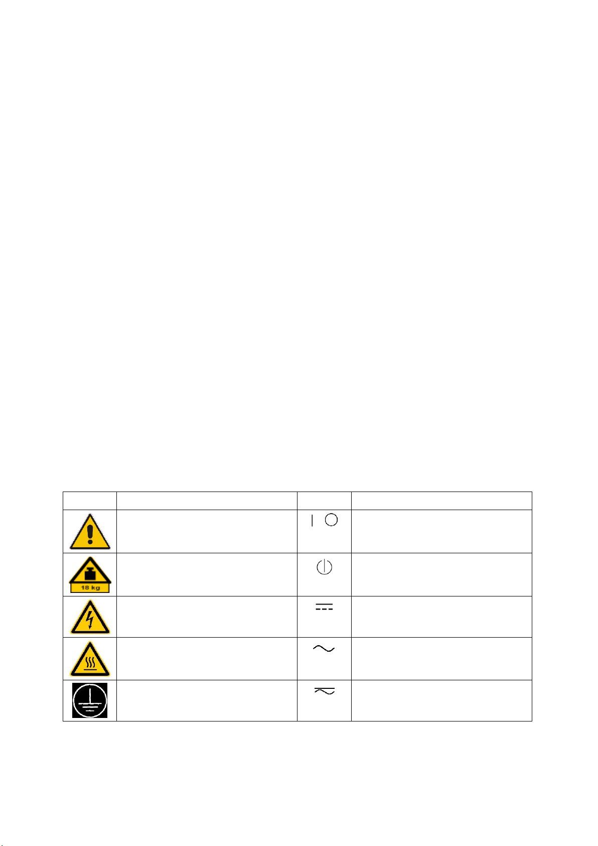
Symbol
Meaning
Symbol
Meaning
Notice, general danger location
Observe product documentation
ON/OFF Power
Caution when handling heavy equipment
Standby indication
Danger of electric shock
Direct current (DC)
Always read through and comply with the following safety instructions!
All plants and locations of the Rohde & Schwarz group of companies make every effort to keep the safety
standards of our products up to date and to offer our customers the highest possible degree of safety. Our
products and the auxiliary equipment they require are designed, built and tested in accordance with the
safety standards that apply in each case. Compliance with these standards is continuously monitored by
our quality assurance system. The product described here has been designed, built and tested in
accordance with the EC Certificate of Conformity and has left the manufacturer’s plant in a condition fully
complying with safety standards. To maintain this condition and to ensure safe operation, you must
observe all instructions and warnings provided in this manual. If you have any questions regarding these
safety instructions, the Rohde & Schwarz group of companies will be happy to answer them.
Furthermore, it is your responsibility to use the product in an appropriate manner. This product is designed
for use solely in industrial and laboratory environments or, if expressly permitted, also in the field and must
not be used in any way that may cause personal injury or property damage. You are responsible if the
product is used for any purpose other than its designated purpose or in disregard of the manufacturer's
instructions. The manufacturer shall assume no responsibility for such use of the product.
The product is used for its designated purpose if it is used in accordance with its product documentation
and within its performance limits (see data sheet, documentation, the following safety instructions). Using
the product requires technical skills and, in some cases, a basic knowledge of English. It is therefore
essential that only skilled and specialized staff or thoroughly trained personnel with the required skills be
allowed to use the product. If personal safety gear is required for using Rohde & Schwarz products, this
will be indicated at the appropriate place in the product documentation. Keep the basic safety instructions
and the product documentation in a safe place and pass them on to the subsequent users.
Observing the safety instructions will help prevent personal injury or damage of any kind caused by
dangerous situations. Therefore, carefully read through and adhere to the following safety instructions
before and when using the product. It is also absolutely essential to observe the additional safety
instructions on personal safety, for example, that appear in relevant parts of the product documentation. In
these safety instructions, the word "product" refers to all merchandise sold and distributed by the Rohde &
Schwarz group of companies, including instruments, systems and all accessories. For product-specific
information, see the data sheet and the product documentation.
Safety labels on products
The following safety labels are used on products to warn against risks and dangers.
1171.0000.42 - 09 Page 1
Page 4

Basic Safety Instructions
Symbol
Meaning
Symbol
Meaning
Caution ! Hot surface
Alternating current (AC)
Protective conductor terminal
To identify any terminal which is intended for
connection to an external conductor for
protection against electric shock in case of a
fault, or the terminal of a protective earth
Direct/alternating current (DC/AC)
Earth (Ground)
Class II Equipment
to identify equipment meeting the safety
requirements specified for Class II equipment
(device protected by double or reinforced
insulation)
Frame or chassis Ground terminal
EU labeling for batteries and accumulators
For additional information, see section "Waste
disposal/Environmental protection", item 1.
Be careful when handling electrostatic sensitive
devices
EU labeling for separate collection of electrical
and electronic devices
For additional information, see section "Waste
disposal/Environmental protection", item 2.
Warning! Laser radiation
For additional information, see section
"Operation", item 7.
Indicates a hazardous situation which, if not avoided, will result in death or
serious injury.
Indicates a hazardous situation which, if not avoided, could result in death or
serious injury.
Indicates a hazardous situation which, if not avoided, could result in minor or
moderate injury.
Indicates information considered important, but not hazard-related, e.g.
messages relating to property damage.
In the product documentation, the word ATTENTION is used synonymously.
Signal words and their meaning
The following signal words are used in the product documentation in order to warn the reader about risks
and dangers.
These signal words are in accordance with the standard definition for civil applications in the European
Economic Area. Definitions that deviate from the standard definition may also exist in other economic
areas or military applications. It is therefore essential to make sure that the signal words described here
are always used only in connection with the related product documentation and the related product. The
use of signal words in connection with unrelated products or documentation can result in misinterpretation
and in personal injury or material damage.
1171.0000.42 - 09 Page 2
Page 5

Basic Safety Instructions
Operating states and operating positions
The product may be operated only under the operating conditions and in the positions specified by the
manufacturer, without the product's ventilation being obstructed. If the manufacturer's specifications are
not observed, this can result in electric shock, fire and/or serious personal injury or death. Applicable local
or national safety regulations and rules for the prevention of accidents must be observed in all work
performed.
1. Unless otherwise specified, the following requirements apply to Rohde & Schwarz products:
predefined operating position is always with the housing floor facing down, IP protection 2X, use only
indoors, max. operating altitude 2000 m above sea level, max. transport altitude 4500 m above sea
level. A tolerance of ±10 % shall apply to the nominal voltage and ±5 % to the nominal frequency,
overvoltage category 2, pollution degree 2.
2. Do not place the product on surfaces, vehicles, cabinets or tables that for reasons of weight or stability
are unsuitable for this purpose. Always follow the manufacturer's installation instructions when
installing the product and fastening it to objects or structures (e.g. walls and shelves). An installation
that is not carried out as described in the product documentation could result in personal injury or
even death.
3. Do not place the product on heat-generating devices such as radiators or fan heaters. The ambient
temperature must not exceed the maximum temperature specified in the product documentation or in
the data sheet. Product overheating can cause electric shock, fire and/or serious personal injury or
even death.
Electrical safety
If the information on electrical safety is not observed either at all or to the extent necessary, electric shock,
fire and/or serious personal injury or death may occur.
1. Prior to switching on the product, always ensure that the nominal voltage setting on the product
matches the nominal voltage of the mains-supply network. If a different voltage is to be set, the power
fuse of the product may have to be changed accordingly.
2. In the case of products of safety class I with movable power cord and connector, operation is
permitted only on sockets with a protective conductor contact and protective conductor.
3. Intentionally breaking the protective conductor either in the feed line or in the product itself is not
permitted. Doing so can result in the danger of an electric shock from the product. If extension cords
or connector strips are implemented, they must be checked on a regular basis to ensure that they are
safe to use.
4. If there is no power switch for disconnecting the product from the mains, or if the power switch is not
suitable for this purpose, use the plug of the connecting cable to disconnect the product from the
mains. In such cases, always ensure that the power plug is easily reachable and accessible at all
times. For example, if the power plug is the disconnecting device, the length of the connecting cable
must not exceed 3 m. Functional or electronic switches are not suitable for providing disconnection
from the AC supply network. If products without power switches are integrated into racks or systems,
the disconnecting device must be provided at the system level.
5. Never use the product if the power cable is damaged. Check the power cables on a regular basis to
ensure that they are in proper operating condition. By taking appropriate safety measures and
carefully laying the power cable, ensure that the cable cannot be damaged and that no one can be
hurt by, for example, tripping over the cable or suffering an electric shock.
1171.0000.42 - 09 Page 3
Page 6

Basic Safety Instructions
6. The product may be operated only from TN/TT supply networks fuse-protected with max. 16 A (higher
fuse only after consulting with the Rohde & Schwarz group of companies).
7. Do not insert the plug into sockets that are dusty or dirty. Insert the plug firmly and all the way into the
socket provided for this purpose. Otherwise, sparks that result in fire and/or injuries may occur.
8. Do not overload any sockets, extension cords or connector strips; doing so can cause fire or electric
shocks.
9. For measurements in circuits with voltages V
> 30 V, suitable measures (e.g. appropriate
rms
measuring equipment, fuse protection, current limiting, electrical separation, insulation) should be
taken to avoid any hazards.
10. Ensure that the connections with information technology equipment, e.g. PCs or other industrial
computers, comply with the IEC 60950-1 / EN 60950-1 or IEC 61010-1 / EN 61010-1 standards that
apply in each case.
11. Unless expressly permitted, never remove the cover or any part of the housing while the product is in
operation. Doing so will expose circuits and components and can lead to injuries, fire or damage to the
product.
12. If a product is to be permanently installed, the connection between the protective conductor terminal
on site and the product's protective conductor must be made first before any other connection is
made. The product may be installed and connected only by a licensed electrician.
13. For permanently installed equipment without built-in fuses, circuit breakers or similar protective
devices, the supply circuit must be fuse-protected in such a way that anyone who has access to the
product, as well as the product itself, is adequately protected from injury or damage.
14. Use suitable overvoltage protection to ensure that no overvoltage (such as that caused by a bolt of
lightning) can reach the product. Otherwise, the person operating the product will be exposed to the
danger of an electric shock.
15. Any object that is not designed to be placed in the openings of the housing must not be used for this
purpose. Doing so can cause short circuits inside the product and/or electric shocks, fire or injuries.
16. Unless specified otherwise, products are not liquid-proof (see also section "Operating states and
operating positions", item 1). Therefore, the equipment must be protected against penetration by
liquids. If the necessary precautions are not taken, the user may suffer electric shock or the product
itself may be damaged, which can also lead to personal injury.
17. Never use the product under conditions in which condensation has formed or can form in or on the
product, e.g. if the product has been moved from a cold to a warm environment. Penetration by water
increases the risk of electric shock.
18. Prior to cleaning the product, disconnect it completely from the power supply (e.g. AC supply network
or battery). Use a soft, non-linting cloth to clean the product. Never use chemical cleaning agents such
as alcohol, acetone or diluents for cellulose lacquers.
Operation
1. Operating the products requires special training and intense concentration. Make sure that persons
who use the products are physically, mentally and emotionally fit enough to do so; otherwise, injuries
or material damage may occur. It is the responsibility of the employer/operator to select suitable
personnel for operating the products.
1171.0000.42 - 09 Page 4
Page 7

Basic Safety Instructions
2. Before you move or transport the product, read and observe the section titled "Transport".
3. As with all industrially manufactured goods, the use of substances that induce an allergic reaction
(allergens) such as nickel cannot be generally excluded. If you develop an allergic reaction (such as a
skin rash, frequent sneezing, red eyes or respiratory difficulties) when using a Rohde & Schwarz
product, consult a physician immediately to determine the cause and to prevent health problems or
stress.
4. Before you start processing the product mechanically and/or thermally, or before you take it apart, be
sure to read and pay special attention to the section titled "Waste disposal/Environmental protection",
item 1.
5. Depending on the function, certain products such as RF radio equipment can produce an elevated
level of electromagnetic radiation. Considering that unborn babies require increased protection,
pregnant women must be protected by appropriate measures. Persons with pacemakers may also be
exposed to risks from electromagnetic radiation. The employer/operator must evaluate workplaces
where there is a special risk of exposure to radiation and, if necessary, take measures to avert the
potential danger.
6. Should a fire occur, the product may release hazardous substances (gases, fluids, etc.) that can
cause health problems. Therefore, suitable measures must be taken, e.g. protective masks and
protective clothing must be worn.
7. Laser products are given warning labels that are standardized according to their laser class. Lasers
can cause biological harm due to the properties of their radiation and due to their extremely
concentrated electromagnetic power. If a laser product (e.g. a CD/DVD drive) is integrated into a
Rohde & Schwarz product, absolutely no other settings or functions may be used as described in the
product documentation. The objective is to prevent personal injury (e.g. due to laser beams).
8. EMC classes (in line with EN 55011/CISPR 11, and analogously with EN 55022/CISPR 22,
EN 55032/CISPR 32)
Class A equipment:
Equipment suitable for use in all environments except residential environments and environments
that are directly connected to a low-voltage supply network that supplies residential buildings
Note: Class A equipment is intended for use in an industrial environment. This equipment may
cause radio disturbances in residential environments, due to possible conducted as well as
radiated disturbances. In this case, the operator may be required to take appropriate measures to
eliminate these disturbances.
Class B equipment:
Equipment suitable for use in residential environments and environments that are directly
connected to a low-voltage supply network that supplies residential buildings
Repair and service
1. The product may be opened only by authorized, specially trained personnel. Before any work is
performed on the product or before the product is opened, it must be disconnected from the AC supply
network. Otherwise, personnel will be exposed to the risk of an electric shock.
1171.0000.42 - 09 Page 5
Page 8

Basic Safety Instructions
2. Adjustments, replacement of parts, maintenance and repair may be performed only by electrical
experts authorized by Rohde & Schwarz. Only original parts may be used for replacing parts relevant
to safety (e.g. power switches, power transformers, fuses). A safety test must always be performed
after parts relevant to safety have been replaced (visual inspection, protective conductor test,
insulation resistance measurement, leakage current measurement, functional test). This helps ensure
the continued safety of the product.
Batteries and rechargeable batteries/cells
If the information regarding batteries and rechargeable batteries/cells is not observed either at all or to the
extent necessary, product users may be exposed to the risk of explosions, fire and/or serious personal
injury, and, in some cases, death. Batteries and rechargeable batteries with alkaline electrolytes (e.g.
lithium cells) must be handled in accordance with the EN 62133 standard.
1. Cells must not be taken apart or crushed.
2. Cells or batteries must not be exposed to heat or fire. Storage in direct sunlight must be avoided.
Keep cells and batteries clean and dry. Clean soiled connectors using a dry, clean cloth.
3. Cells or batteries must not be short-circuited. Cells or batteries must not be stored in a box or in a
drawer where they can short-circuit each other, or where they can be short-circuited by other
conductive materials. Cells and batteries must not be removed from their original packaging until they
are ready to be used.
4. Cells and batteries must not be exposed to any mechanical shocks that are stronger than permitted.
5. If a cell develops a leak, the fluid must not be allowed to come into contact with the skin or eyes. If
contact occurs, wash the affected area with plenty of water and seek medical aid.
6. Improperly replacing or charging cells or batteries that contain alkaline electrolytes (e.g. lithium cells)
can cause explosions. Replace cells or batteries only with the matching Rohde & Schwarz type (see
parts list) in order to ensure the safety of the product.
7. Cells and batteries must be recycled and kept separate from residual waste. Rechargeable batteries
and normal batteries that contain lead, mercury or cadmium are hazardous waste. Observe the
national regulations regarding waste disposal and recycling.
8. Follow the transport stipulations of the carrier (IATA-DGR, IMDG-Code, ADR, RID) when returning
lithium batteries to Rohde & Schwarz subsidiaries.
Transport
1. The product may be very heavy. Therefore, the product must be handled with care. In some cases,
the user may require a suitable means of lifting or moving the product (e.g. with a lift-truck) to avoid
back or other physical injuries.
2. Handles on the products are designed exclusively to enable personnel to transport the product. It is
therefore not permissible to use handles to fasten the product to or on transport equipment such as
cranes, fork lifts, wagons, etc. The user is responsible for securely fastening the products to or on the
means of transport or lifting. Observe the safety regulations of the manufacturer of the means of
transport or lifting. Noncompliance can result in personal injury or material damage.
1171.0000.42 - 09 Page 6
Page 9

Instrucciones de seguridad elementales
3. If you use the product in a vehicle, it is the sole responsibility of the driver to drive the vehicle safely
and properly. The manufacturer assumes no responsibility for accidents or collisions. Never use the
product in a moving vehicle if doing so could distract the driver of the vehicle. Adequately secure the
product in the vehicle to prevent injuries or other damage in the event of an accident.
Waste disposal/Environmental protection
1. Specially marked equipment has a battery or accumulator that must not be disposed of with unsorted
municipal waste, but must be collected separately. It may only be disposed of at a suitable collection
point or via a Rohde & Schwarz customer service center.
2. Waste electrical and electronic equipment must not be disposed of with unsorted municipal waste, but
must be collected separately.
Rohde & Schwarz GmbH & Co. KG has developed a disposal concept and takes full responsibility for
take-back obligations and disposal obligations for manufacturers within the EU. Contact your
Rohde & Schwarz customer service center for environmentally responsible disposal of the product.
3. If products or their components are mechanically and/or thermally processed in a manner that goes
beyond their intended use, hazardous substances (heavy-metal dust such as lead, beryllium, nickel)
may be released. For this reason, the product may only be disassembled by specially trained
personnel. Improper disassembly may be hazardous to your health. National waste disposal
regulations must be observed.
4. If handling the product releases hazardous substances or fuels that must be disposed of in a special
way, e.g. coolants or engine oils that must be replenished regularly, the safety instructions of the
manufacturer of the hazardous substances or fuels and the applicable regional waste disposal
regulations must be observed. Also observe the relevant safety instructions in the product
documentation. The improper disposal of hazardous substances or fuels can cause health problems
and lead to environmental damage.
For additional information about environmental protection, visit the Rohde & Schwarz website.
Instrucciones de seguridad elementales
¡Es imprescindible leer y cumplir las siguientes instrucciones e informaciones de seguridad!
El principio del grupo de empresas Rohde & Schwarz consiste en tener nuestros productos siempre al día
con los estándares de seguridad y de ofrecer a nuestros clientes el máximo grado de seguridad. Nuestros
productos y todos los equipos adicionales son siempre fabricados y examinados según las normas de
seguridad vigentes. Nuestro sistema de garantía de calidad controla constantemente que sean cumplidas
estas normas. El presente producto ha sido fabricado y examinado según el certificado de conformidad
de la UE y ha salido de nuestra planta en estado impecable según los estándares técnicos de seguridad.
Para poder preservar este estado y garantizar un funcionamiento libre de peligros, el usuario deberá
atenerse a todas las indicaciones, informaciones de seguridad y notas de alerta. El grupo de empresas
Rohde & Schwarz está siempre a su disposición en caso de que tengan preguntas referentes a estas
informaciones de seguridad.
1171.0000.42 - 09 Page 7
Page 10
Instrucciones de seguridad elementales
Símbolo
Significado
Símbolo
Significado
Aviso: punto de peligro general
Observar la documentación del producto
Tensión de alimentación de PUESTA EN
MARCHA / PARADA
Atención en el manejo de dispositivos de peso
elevado
Indicación de estado de espera (standby)
Peligro de choque eléctrico
Corriente continua (DC)
Advertencia: superficie caliente
Corriente alterna (AC)
Conexión a conductor de protección
Corriente continua / Corriente alterna (DC/AC)
Además queda en la responsabilidad del usuario utilizar el producto en la forma debida. Este producto
está destinado exclusivamente al uso en la industria y el laboratorio o, si ha sido expresamente
autorizado, para aplicaciones de campo y de ninguna manera deberá ser utilizado de modo que alguna
persona/cosa pueda sufrir daño. El uso del producto fuera de sus fines definidos o sin tener en cuenta las
instrucciones del fabricante queda en la responsabilidad del usuario. El fabricante no se hace en ninguna
forma responsable de consecuencias a causa del mal uso del producto.
Se parte del uso correcto del producto para los fines definidos si el producto es utilizado conforme a las
indicaciones de la correspondiente documentación del producto y dentro del margen de rendimiento
definido (ver hoja de datos, documentación, informaciones de seguridad que siguen). El uso del producto
hace necesarios conocimientos técnicos y ciertos conocimientos del idioma inglés. Por eso se debe tener
en cuenta que el producto solo pueda ser operado por personal especializado o personas instruidas en
profundidad con las capacidades correspondientes. Si fuera necesaria indumentaria de seguridad para el
uso de productos de Rohde & Schwarz, encontraría la información debida en la documentación del
producto en el capítulo correspondiente. Guarde bien las informaciones de seguridad elementales, así
como la documentación del producto, y entréguelas a usuarios posteriores.
Tener en cuenta las informaciones de seguridad sirve para evitar en lo posible lesiones o daños por
peligros de toda clase. Por eso es imprescindible leer detalladamente y comprender por completo las
siguientes informaciones de seguridad antes de usar el producto, y respetarlas durante el uso del
producto. Deberán tenerse en cuenta todas las demás informaciones de seguridad, como p. ej. las
referentes a la protección de personas, que encontrarán en el capítulo correspondiente de la
documentación del producto y que también son de obligado cumplimiento. En las presentes
informaciones de seguridad se recogen todos los objetos que distribuye el grupo de empresas
Rohde & Schwarz bajo la denominación de "producto", entre ellos también aparatos, instalaciones así
como toda clase de accesorios. Los datos específicos del producto figuran en la hoja de datos y en la
documentación del producto.
Señalización de seguridad de los productos
Las siguientes señales de seguridad se utilizan en los productos para advertir sobre riesgos y peligros.
1171.0000.42 - 09 Page 8
Page 11

Instrucciones de seguridad elementales
Símbolo
Significado
Símbolo
Significado
Conexión a tierra
El aparato está protegido en su totalidad por un
aislamiento doble (reforzado)
Conexión a masa
Distintivo de la UE para baterías y
acumuladores
Más información en la sección
"Eliminación/protección del medio ambiente",
punto 1.
Aviso: Cuidado en el manejo de dispositivos
sensibles a la electrostática (ESD)
Distintivo de la UE para la eliminación por
separado de dispositivos eléctricos y
electrónicos
Más información en la sección
"Eliminación/protección del medio ambiente",
punto 2.
Advertencia: rayo láser
Más información en la sección
"Funcionamiento", punto 7.
Indica una situación de peligro que, si no se evita, causa lesiones
graves o incluso la muerte.
Indica una situación de peligro que, si no se evita, puede causar
lesiones graves o incluso la muerte.
Indica una situación de peligro que, si no se evita, puede causar
lesiones leves o moderadas.
Indica información que se considera importante, pero no en relación
con situaciones de peligro; p. ej., avisos sobre posibles daños
materiales.
En la documentación del producto se emplea de forma sinónima el
término CUIDADO.
Palabras de señal y su significado
En la documentación del producto se utilizan las siguientes palabras de señal con el fin de advertir contra
riesgos y peligros.
Las palabras de señal corresponden a la definición habitual para aplicaciones civiles en el área
económica europea. Pueden existir definiciones diferentes a esta definición en otras áreas económicas o
en aplicaciones militares. Por eso se deberá tener en cuenta que las palabras de señal aquí descritas
sean utilizadas siempre solamente en combinación con la correspondiente documentación del producto y
solamente en combinación con el producto correspondiente. La utilización de las palabras de señal en
combinación con productos o documentaciones que no les correspondan puede llevar a interpretaciones
equivocadas y tener por consecuencia daños en personas u objetos.
1171.0000.42 - 09 Page 9
Page 12

Instrucciones de seguridad elementales
Estados operativos y posiciones de funcionamiento
El producto solamente debe ser utilizado según lo indicado por el fabricante respecto a los estados
operativos y posiciones de funcionamiento sin que se obstruya la ventilación. Si no se siguen las
indicaciones del fabricante, pueden producirse choques eléctricos, incendios y/o lesiones graves con
posible consecuencia de muerte. En todos los trabajos deberán ser tenidas en cuenta las normas
nacionales y locales de seguridad del trabajo y de prevención de accidentes.
1. Si no se convino de otra manera, es para los productos Rohde & Schwarz válido lo que sigue:
como posición de funcionamiento se define por principio la posición con el suelo de la caja para
abajo, modo de protección IP 2X, uso solamente en estancias interiores, utilización hasta 2000 m
sobre el nivel del mar, transporte hasta 4500 m sobre el nivel del mar. Se aplicará una tolerancia de
±10 % sobre el voltaje nominal y de ±5 % sobre la frecuencia nominal. Categoría de sobrecarga
eléctrica 2, índice de suciedad 2.
2. No sitúe el producto encima de superficies, vehículos, estantes o mesas, que por sus características
de peso o de estabilidad no sean aptos para él. Siga siempre las instrucciones de instalación del
fabricante cuando instale y asegure el producto en objetos o estructuras (p. ej. paredes y estantes). Si
se realiza la instalación de modo distinto al indicado en la documentación del producto, se pueden
causar lesiones o, en determinadas circunstancias, incluso la muerte.
3. No ponga el producto sobre aparatos que generen calor (p. ej. radiadores o calefactores). La
temperatura ambiente no debe superar la temperatura máxima especificada en la documentación del
producto o en la hoja de datos. En caso de sobrecalentamiento del producto, pueden producirse
choques eléctricos, incendios y/o lesiones graves con posible consecuencia de muerte.
Seguridad eléctrica
Si no se siguen (o se siguen de modo insuficiente) las indicaciones del fabricante en cuanto a seguridad
eléctrica, pueden producirse choques eléctricos, incendios y/o lesiones graves con posible consecuencia
de muerte.
1. Antes de la puesta en marcha del producto se deberá comprobar siempre que la tensión
preseleccionada en el producto coincida con la de la red de alimentación eléctrica. Si es necesario
modificar el ajuste de tensión, también se deberán cambiar en caso dado los fusibles
correspondientes del producto.
2. Los productos de la clase de protección I con alimentación móvil y enchufe individual solamente
podrán enchufarse a tomas de corriente con contacto de seguridad y con conductor de protección
conectado.
3. Queda prohibida la interrupción intencionada del conductor de protección, tanto en la toma de
corriente como en el mismo producto. La interrupción puede tener como consecuencia el riesgo de
que el producto sea fuente de choques eléctricos. Si se utilizan cables alargadores o regletas de
enchufe, deberá garantizarse la realización de un examen regular de los mismos en cuanto a su
estado técnico de seguridad.
4. Si el producto no está equipado con un interruptor para desconectarlo de la red, o bien si el
interruptor existente no resulta apropiado para la desconexión de la red, el enchufe del cable de
conexión se deberá considerar como un dispositivo de desconexión.
El dispositivo de desconexión se debe poder alcanzar fácilmente y debe estar siempre bien accesible.
Si, p. ej., el enchufe de conexión a la red es el dispositivo de desconexión, la longitud del cable de
conexión no debe superar 3 m).
Los interruptores selectores o electrónicos no son aptos para el corte de la red eléctrica. Si se
1171.0000.42 - 09 Page 10
Page 13

Instrucciones de seguridad elementales
integran productos sin interruptor en bastidores o instalaciones, se deberá colocar el interruptor en el
nivel de la instalación.
5. No utilice nunca el producto si está dañado el cable de conexión a red. Compruebe regularmente el
correcto estado de los cables de conexión a red. Asegúrese, mediante las medidas de protección y
de instalación adecuadas, de que el cable de conexión a red no pueda ser dañado o de que nadie
pueda ser dañado por él, p. ej. al tropezar o por un choque eléctrico.
6. Solamente está permitido el funcionamiento en redes de alimentación TN/TT aseguradas con fusibles
de 16 A como máximo (utilización de fusibles de mayor amperaje solo previa consulta con el grupo de
empresas Rohde & Schwarz).
7. Nunca conecte el enchufe en tomas de corriente sucias o llenas de polvo. Introduzca el enchufe por
completo y fuertemente en la toma de corriente. La no observación de estas medidas puede provocar
chispas, fuego y/o lesiones.
8. No sobrecargue las tomas de corriente, los cables alargadores o las regletas de enchufe ya que esto
podría causar fuego o choques eléctricos.
9. En las mediciones en circuitos de corriente con una tensión U
> 30 V se deberán tomar las medidas
eff
apropiadas para impedir cualquier peligro (p. ej. medios de medición adecuados, seguros, limitación
de tensión, corte protector, aislamiento etc.).
10. Para la conexión con dispositivos informáticos como un PC o un ordenador industrial, debe
comprobarse que éstos cumplan los estándares IEC60950-1/EN60950-1 o IEC61010-1/EN 61010-1
válidos en cada caso.
11. A menos que esté permitido expresamente, no retire nunca la tapa ni componentes de la carcasa
mientras el producto esté en servicio. Esto pone a descubierto los cables y componentes eléctricos y
puede causar lesiones, fuego o daños en el producto.
12. Si un producto se instala en un lugar fijo, se deberá primero conectar el conductor de protección fijo
con el conductor de protección del producto antes de hacer cualquier otra conexión. La instalación y
la conexión deberán ser efectuadas por un electricista especializado.
13. En el caso de dispositivos fijos que no estén provistos de fusibles, interruptor automático ni otros
mecanismos de seguridad similares, el circuito de alimentación debe estar protegido de modo que
todas las personas que puedan acceder al producto, así como el producto mismo, estén a salvo de
posibles daños.
14. Todo producto debe estar protegido contra sobretensión (debida p. ej. a una caída del rayo) mediante
los correspondientes sistemas de protección. Si no, el personal que lo utilice quedará expuesto al
peligro de choque eléctrico.
15. No debe introducirse en los orificios de la caja del aparato ningún objeto que no esté destinado a ello.
Esto puede producir cortocircuitos en el producto y/o puede causar choques eléctricos, fuego o
lesiones.
16. Salvo indicación contraria, los productos no están impermeabilizados (ver también el capítulo
"Estados operativos y posiciones de funcionamiento", punto 1). Por eso es necesario tomar las
medidas necesarias para evitar la entrada de líquidos. En caso contrario, existe peligro de choque
eléctrico para el usuario o de daños en el producto, que también pueden redundar en peligro para las
personas.
1171.0000.42 - 09 Page 11
Page 14

Instrucciones de seguridad elementales
17. No utilice el producto en condiciones en las que pueda producirse o ya se hayan producido
condensaciones sobre el producto o en el interior de éste, como p. ej. al desplazarlo de un lugar frío a
otro caliente. La entrada de agua aumenta el riesgo de choque eléctrico.
18. Antes de la limpieza, desconecte por completo el producto de la alimentación de tensión (p. ej. red de
alimentación o batería). Realice la limpieza de los aparatos con un paño suave, que no se deshilache.
No utilice bajo ningún concepto productos de limpieza químicos como alcohol, acetona o diluyentes
para lacas nitrocelulósicas.
Funcionamiento
1. El uso del producto requiere instrucciones especiales y una alta concentración durante el manejo.
Debe asegurarse que las personas que manejen el producto estén a la altura de los requerimientos
necesarios en cuanto a aptitudes físicas, psíquicas y emocionales, ya que de otra manera no se
pueden excluir lesiones o daños de objetos. El empresario u operador es responsable de seleccionar
el personal usuario apto para el manejo del producto.
2. Antes de desplazar o transportar el producto, lea y tenga en cuenta el capítulo "Transporte".
3. Como con todo producto de fabricación industrial no puede quedar excluida en general la posibilidad
de que se produzcan alergias provocadas por algunos materiales empleados ―los llamados
alérgenos (p. ej. el níquel)―. Si durante el manejo de productos Rohde & Schwarz se producen
reacciones alérgicas, como p. ej. irritaciones cutáneas, estornudos continuos, enrojecimiento de la
conjuntiva o dificultades respiratorias, debe avisarse inmediatamente a un médico para investigar las
causas y evitar cualquier molestia o daño a la salud.
4. Antes de la manipulación mecánica y/o térmica o el desmontaje del producto, debe tenerse en cuenta
imprescindiblemente el capítulo "Eliminación/protección del medio ambiente", punto 1.
5. Ciertos productos, como p. ej. las instalaciones de radiocomunicación RF, pueden a causa de su
función natural, emitir una radiación electromagnética aumentada. Deben tomarse todas las medidas
necesarias para la protección de las mujeres embarazadas. También las personas con marcapasos
pueden correr peligro a causa de la radiación electromagnética. El empresario/operador tiene la
obligación de evaluar y señalizar las áreas de trabajo en las que exista un riesgo elevado de
exposición a radiaciones.
6. Tenga en cuenta que en caso de incendio pueden desprenderse del producto sustancias tóxicas
(gases, líquidos etc.) que pueden generar daños a la salud. Por eso, en caso de incendio deben
usarse medidas adecuadas, como p. ej. máscaras antigás e indumentaria de protección.
7. Los productos con láser están provistos de indicaciones de advertencia normalizadas en función de la
clase de láser del que se trate. Los rayos láser pueden provocar daños de tipo biológico a causa de
las propiedades de su radiación y debido a su concentración extrema de potencia electromagnética.
En caso de que un producto Rohde & Schwarz contenga un producto láser (p. ej. un lector de
CD/DVD), no debe usarse ninguna otra configuración o función aparte de las descritas en la
documentación del producto, a fin de evitar lesiones (p. ej. debidas a irradiación láser).
8. Clases de compatibilidad electromagnética (conforme a EN 55011 / CISPR 11; y en analogía con EN
55022 / CISPR 22, EN 55032 / CISPR 32)
Aparato de clase A:
Aparato adecuado para su uso en todos los entornos excepto en los residenciales y en aquellos
conectados directamente a una red de distribución de baja tensión que suministra corriente a
edificios residenciales.
Nota: Los aparatos de clase A están destinados al uso en entornos industriales. Estos aparatos
1171.0000.42 - 09 Page 12
Page 15

Instrucciones de seguridad elementales
pueden causar perturbaciones radioeléctricas en entornos residenciales debido a posibles
perturbaciones guiadas o radiadas. En este caso, se le podrá solicitar al operador que tome las
medidas adecuadas para eliminar estas perturbaciones.
Aparato de clase B:
Aparato adecuado para su uso en entornos residenciales, así como en aquellos conectados
directamente a una red de distribución de baja tensión que suministra corriente a edificios
residenciales.
Reparación y mantenimiento
1. El producto solamente debe ser abierto por personal especializado con autorización para ello. Antes
de manipular el producto o abrirlo, es obligatorio desconectarlo de la tensión de alimentación, para
evitar toda posibilidad de choque eléctrico.
2. El ajuste, el cambio de partes, el mantenimiento y la reparación deberán ser efectuadas solamente
por electricistas autorizados por Rohde & Schwarz. Si se reponen partes con importancia para los
aspectos de seguridad (p. ej. el enchufe, los transformadores o los fusibles), solamente podrán ser
sustituidos por partes originales. Después de cada cambio de partes relevantes para la seguridad
deberá realizarse un control de seguridad (control a primera vista, control del conductor de
protección, medición de resistencia de aislamiento, medición de la corriente de fuga, control de
funcionamiento). Con esto queda garantizada la seguridad del producto.
Baterías y acumuladores o celdas
Si no se siguen (o se siguen de modo insuficiente) las indicaciones en cuanto a las baterías y
acumuladores o celdas, pueden producirse explosiones, incendios y/o lesiones graves con posible
consecuencia de muerte. El manejo de baterías y acumuladores con electrolitos alcalinos (p. ej. celdas de
litio) debe seguir el estándar EN 62133.
1. No deben desmontarse, abrirse ni triturarse las celdas.
2. Las celdas o baterías no deben someterse a calor ni fuego. Debe evitarse el almacenamiento a la luz
directa del sol. Las celdas y baterías deben mantenerse limpias y secas. Limpiar las conexiones
sucias con un paño seco y limpio.
3. Las celdas o baterías no deben cortocircuitarse. Es peligroso almacenar las celdas o baterías en
estuches o cajones en cuyo interior puedan cortocircuitarse por contacto recíproco o por contacto con
otros materiales conductores. No deben extraerse las celdas o baterías de sus embalajes originales
hasta el momento en que vayan a utilizarse.
4. Las celdas o baterías no deben someterse a impactos mecánicos fuertes indebidos.
5. En caso de falta de estanqueidad de una celda, el líquido vertido no debe entrar en contacto con la
piel ni los ojos. Si se produce contacto, lavar con agua abundante la zona afectada y avisar a un
médico.
6. En caso de cambio o recarga inadecuados, las celdas o baterías que contienen electrolitos alcalinos
(p. ej. las celdas de litio) pueden explotar. Para garantizar la seguridad del producto, las celdas o
baterías solo deben ser sustituidas por el tipo Rohde & Schwarz correspondiente (ver lista de
recambios).
7. Las baterías y celdas deben reciclarse y no deben tirarse a la basura doméstica. Las baterías o
acumuladores que contienen plomo, mercurio o cadmio deben tratarse como residuos especiales.
Respete en esta relación las normas nacionales de eliminación y reciclaje.
1171.0000.42 - 09 Page 13
Page 16

Instrucciones de seguridad elementales
8. En caso de devolver baterías de litio a las filiales de Rohde & Schwarz, debe cumplirse las
normativas sobre los modos de transporte (IATA-DGR, código IMDG, ADR, RID).
Transporte
1. El producto puede tener un peso elevado. Por eso es necesario desplazarlo o transportarlo con
precaución y, si es necesario, usando un sistema de elevación adecuado (p. ej. una carretilla
elevadora), a fin de evitar lesiones en la espalda u otros daños personales.
2. Las asas instaladas en los productos sirven solamente de ayuda para el transporte del producto por
personas. Por eso no está permitido utilizar las asas para la sujeción en o sobre medios de transporte
como p. ej. grúas, carretillas elevadoras de horquilla, carros etc. Es responsabilidad suya fijar los
productos de manera segura a los medios de transporte o elevación. Para evitar daños personales o
daños en el producto, siga las instrucciones de seguridad del fabricante del medio de transporte o
elevación utilizado.
3. Si se utiliza el producto dentro de un vehículo, recae de manera exclusiva en el conductor la
responsabilidad de conducir el vehículo de manera segura y adecuada. El fabricante no asumirá
ninguna responsabilidad por accidentes o colisiones. No utilice nunca el producto dentro de un
vehículo en movimiento si esto pudiera distraer al conductor. Asegure el producto dentro del vehículo
debidamente para evitar, en caso de un accidente, lesiones u otra clase de daños.
Eliminación/protección del medio ambiente
1. Los dispositivos marcados contienen una batería o un acumulador que no se debe desechar con los
residuos domésticos sin clasificar, sino que debe ser recogido por separado. La eliminación se debe
efectuar exclusivamente a través de un punto de recogida apropiado o del servicio de atención al
cliente de Rohde & Schwarz.
2. Los dispositivos eléctricos usados no se deben desechar con los residuos domésticos sin clasificar,
sino que deben ser recogidos por separado.
Rohde & Schwarz GmbH & Co.KG ha elaborado un concepto de eliminación de residuos y asume
plenamente los deberes de recogida y eliminación para los fabricantes dentro de la UE. Para
desechar el producto de manera respetuosa con el medio ambiente, diríjase a su servicio de atención
al cliente de Rohde & Schwarz.
3. Si se trabaja de manera mecánica y/o térmica cualquier producto o componente más allá del
funcionamiento previsto, pueden liberarse sustancias peligrosas (polvos con contenido de metales
pesados como p. ej. plomo, berilio o níquel). Por eso el producto solo debe ser desmontado por
personal especializado con formación adecuada. Un desmontaje inadecuado puede ocasionar daños
para la salud. Se deben tener en cuenta las directivas nacionales referentes a la eliminación de
residuos.
4. En caso de que durante el trato del producto se formen sustancias peligrosas o combustibles que
deban tratarse como residuos especiales (p. ej. refrigerantes o aceites de motor con intervalos de
cambio definidos), deben tenerse en cuenta las indicaciones de seguridad del fabricante de dichas
sustancias y las normas regionales de eliminación de residuos. Tenga en cuenta también en caso
necesario las indicaciones de seguridad especiales contenidas en la documentación del producto. La
eliminación incorrecta de sustancias peligrosas o combustibles puede causar daños a la salud o
daños al medio ambiente.
Se puede encontrar más información sobre la protección del medio ambiente en la página web de
Rohde & Schwarz.
1171.0000.42 - 09 Page 14
Page 17

Customer Support
Technical support – where and when you need it
For quick, expert help with any Rohde & Schwarz equipment, contact one of our Customer Support
Centers. A team of highly qualified engineers provides telephone support and will work with you to find a
solution to your query on any aspect of the operation, programming or applications of Rohde & Schwarz
equipment.
Up-to-date information and upgrades
To keep your instrument up-to-date and to be informed about new application notes related to your
instrument, please send an e-mail to the Customer Support Center stating your instrument and your wish.
We will take care that you will get the right information.
Europe, Africa, Middle East
North America
Latin America
Asia/Pacific
China
Phone +49 89 4129 12345
customersupport@rohde-schwarz.com
Phone 1-888-TEST-RSA (1-888-837-8772)
customer.support@rsa.rohde-schwarz.com
Phone +1-410-910-7988
customersupport.la@rohde-schwarz.com
Phone +65 65 13 04 88
customersupport.asia@rohde-schwarz.com
Phone +86-800-810-8228 /
+86-400-650-5896
customersupport.china@rohde-schwarz.com
1171.0200.22-06.00
Page 18

R&S®UD1065
3.1 Unpacking and Checking the Instrument................................................................... 8
3.2 Placing or Mounting the Instrument............................................................................9
3.3 Connecting AC Power................................................................................................ 11
3.4 Turning the R&S UD1065 on and off......................................................................... 11
4.1 Front Panel.................................................................................................................. 12
4.2 Rear Panel....................................................................................................................14
Contents
Contents
1 Documentation Overview......................................................................5
2 Welcome to R&S UD1065...................................................................... 6
3 Preparing for Use...................................................................................7
4 Instrument Tour....................................................................................12
5 Setting Up the System.........................................................................16
6 R&S WiGig Tester Software................................................................ 20
6.1 Signal Analysis............................................................................................................20
6.2 Signal Generation....................................................................................................... 22
6.3 Settings........................................................................................................................ 24
6.4 Alignment.....................................................................................................................25
6.5 Info................................................................................................................................25
6.6 Measurement Results................................................................................................. 26
6.7 Remote Control........................................................................................................... 29
List of Commands................................................................................46
3System Manual 1178.4182.02 ─ 04
Page 19

R&S®UD1065
Contents
4System Manual 1178.4182.02 ─ 04
Page 20

R&S®UD1065
Documentation Overview
1 Documentation Overview
This section provides an overview of the R&S UD1065 user documentation. You can
download it from:
http://www.rohde-schwarz.com/manual/ud1065
Getting started manual
Introduces the R&S UD1065 and describes how to set up and start working with the
product. A printed version is included in the delivery.
System manual
The system manual contains the description of the IEEE 802.11ad test system and the
functions available in the R&S WiGig Tester Software. It also provides a complete
description of the remote control commands.
The R&S SMW and R&S RTO have their own documentation. Both are available for
download on the internet on the corresponding product pages.
R&S SMW200A: http://www.rohde-schwarz.com/manual/smw200a
R&S RTO2044: http://www.rohde-schwarz.com/manual/rto
Online help
The online help integrated into the R&S WiGig Tester Software allows you to access
the complete system manual directly.
Basic safety instructions
Contains safety instructions, operating conditions and further important information.
The printed document is included in the delivery.
Data sheet
The data sheet contains the technical specifications of the R&S UD1065.
Open source acknowledgment (OSA)
The open source acknowledgment document provides verbatim license texts of the
used open source software.
See http://www.rohde-schwarz.comproduct/ud1065
5System Manual 1178.4182.02 ─ 04
Page 21

R&S®UD1065
Welcome to R&S UD1065
2 Welcome to R&S UD1065
The R&S UD1065 is a frequency up- / downconverter designed to test IEEE 802.11ad
devices in production and laboratories in an industrial environment. Use the
R&S UD1065 only for its designated purpose, and observe the performance limits and
operating conditions stated in the data sheet.
The R&S UD1065 is part of a system that consists of the following components.
●
R&S UD1065
●
R&S SMW200A vector signal generator
●
R&S RTO2044 oscilloscope
●
R&S WiGig Tester Software
The R&S WiGig Tester Software controls the system.
6System Manual 1178.4182.02 ─ 04
Page 22

R&S®UD1065
Preparing for Use
3 Preparing for Use
Make sure to consider the following information before using the R&S UD1065 for the
first time.
Risk of injury and instrument damage
The instrument must be used in an appropriate manner to prevent electric shock, fire,
personal injury, or damage.
●
Do not open the instrument casing.
●
Read and observe the "Basic Safety Instructions" delivered as a printed brochure
with the instrument.
In addition, read and observe the safety instructions in the following sections.
Notice that the data sheet may specify additional operating conditions.
Risk of instrument damage
Note that the general safety instructions also contain information on operating conditions that prevent damage to the instrument. The instrument's data sheet can contain
additional operating conditions.
Risk of electrostatic discharge (ESD)
Electrostatic discharge (ESD) can damage the electronic components of the instrument
and the device under test (DUT). ESD is most likely to occur when you connect or disconnect a DUT or test fixture to the instrument's test ports. To prevent ESD, use a wrist
strap and cord and connect yourself to the ground, or use a conductive floor mat and
heel strap combination.
For details, refer to the basic safety instructions delivered as a printed brochure with
the instrument.
7System Manual 1178.4182.02 ─ 04
Page 23

R&S®UD1065
Preparing for Use
Unpacking and Checking the Instrument
Risk of instrument damage during operation
An unsuitable operating site or test setup can damage the instrument and connected
devices. Ensure the following operating conditions before you switch on the instrument:
●
All fan openings are unobstructed and the airflow perforations are unimpeded. The
minimum distance from the wall is 10 cm.
●
The instrument is dry and shows no sign of condensation.
●
The instrument is positioned as described in the following sections.
●
The ambient temperature does not exceed the range specified in the data sheet.
●
Signal levels at the input connectors are all within the specified ranges.
●
Signal outputs are correctly connected and are not overloaded.
EMI impact on measurement results
Electromagnetic interference (EMI) may affect the measurement results.
To suppress generated electromagnetic interference (EMI):
●
Use suitable shielded cables of high quality. For example, use double-shielded RF
and LAN cables.
●
Always terminate open cable ends.
●
Note the EMC classification in the data sheet.
● Unpacking and Checking the Instrument.................................................................. 8
● Placing or Mounting the Instrument.......................................................................... 9
● Connecting AC Power.............................................................................................11
● Turning the R&S UD1065 on and off...................................................................... 11
3.1 Unpacking and Checking the Instrument
Unpack the R&S UD1065 carefully and check the contents of the package.
●
Check if all items listed on the delivery note, including this getting started manual,
are included in the delivery.
●
Check the R&S UD1065 for any damage.
If the contents are damaged, immediately contact the carrier who delivered the
package.
●
Keep the box and packing material.
8System Manual 1178.4182.02 ─ 04
Page 24

R&S®UD1065
Preparing for Use
Placing or Mounting the Instrument
Risk of damage during transportation and shipment
Insufficient protection against mechanical and electrostatic effects during transportation
and shipment can damage the instrument.
●
Always make sure that sufficient mechanical and electrostatic protection is provided.
●
When shipping an instrument, the original packaging should be used. If you do not
have the original packaging, use sufficient padding to prevent the instrument from
moving around inside the box. Pack the instrument in antistatic wrap to protect it
from electrostatic charging.
●
Secure the instrument to prevent any movement and other mechanical effects during transportation.
The carrying handles at the front and side of the casing are designed to lift or carry
the instrument. Do not apply an excessive external force to the handles.
Observe the information on transporting heavy instruments in the basic safety instructions included at the front of the printed manual.
Packing material
Retain the original packing material. If the instrument needs to be transported or shipped at a later date, you can use the material to protect the control elements and connectors.
3.2 Placing or Mounting the Instrument
The R&S UD1065 is designed for use under laboratory conditions, either on a bench
top or in a rack.
Benchtop operation
If the R&S UD1065 is operated on a bench top, the surface should be flat. The instrument can be used in horizontal position, standing on its feet, or with the support feet on
the bottom extended.
9System Manual 1178.4182.02 ─ 04
Page 25

R&S®UD1065
Preparing for Use
Placing or Mounting the Instrument
Risk of injury if feet are folded out
The feet may fold in if they are not folded out completely or if the instrument is shifted.
This may cause damage or injury.
●
Fold the feet completely in or completely out to ensure stability of the instrument.
Never shift the instrument when the feet are folded out.
●
When the feet are folded out, do not work under the instrument or place anything
underneath.
●
The feet can break if they are overloaded. The overall load on the folded-out feet
must not exceed 500 N.
F < 500 N
Risk of injury and instrument damage if stacking instruments
A stack of instruments may tilt over and cause injury. Furthermore, the instruments at
the bottom of the stack may be damaged due to the load imposed by the instruments
on top.
Observe the following instructions when stacking instruments:
●
Never stack more than three instruments. If you need to stack more than three
instruments, install them in a rack.
●
The overall load imposed on the lowest instrument must not exceed 500 N.
●
All instruments must have the same dimensions (width and length).
●
If the instruments have foldable feet, fold them in completely.
10System Manual 1178.4182.02 ─ 04
Page 26

R&S®UD1065
Preparing for Use
Turning the R&S UD1065 on and off
Mounting the R&S UD1065 in a rack
The R&S UD1065 can be installed in a rack using a rack adapter kit (order no. see
data sheet). The installation instructions are part of the adapter kit.
Risk of instrument damage in a rack
An insufficient airflow can cause the instrument to overheat, which may disturb the
operation and even cause damage.
Make sure that all fan openings are unobstructed, that the airflow perforations are
unimpeded, and that the minimum distance from the wall is 10 cm.
3.3 Connecting AC Power
In the standard version, the R&S UD1065 is equipped with an AC power supply connector. The R&S UD1065 can be used with different AC power voltages and adapts
itself automatically to it. Refer to the datasheet for the requirements of voltage and frequency. The AC power connector is on the rear panel of the instrument.
For details on the connector, see Chapter 4.2.1, "Power Supply", on page 14.
► Connect the R&S UD1065 to the AC power supply using the supplied power cable.
The R&S UD1065 complies to the specifications of safety class EN61010. Thus,
make sure that you only connect it to a power socket that has a ground contact.
3.4 Turning the R&S UD1065 on and off
After you have established a connection to the power supply, you can turn on the
R&S UD1065.
Turning on the R&S UD1065
► Turn on the main AC power switch on the rear panel of the R&S UD1065 (position
"I").
The instrument is supplied with AC power.
Green "Power" LED on the front panel: R&S UD1065 is running and ready for operation.
Turning off the R&S UD1065
► Turn off the main AC power switch on the rear panel of the R&S UD1065 (position
"0").
The instrument is no longer supplied with AC power.
11System Manual 1178.4182.02 ─ 04
Page 27

R&S®UD1065
Instrument Tour
Front Panel
4 Instrument Tour
The R&S UD1065 has various connectors on the front and rear panel.
● Front Panel..............................................................................................................12
● Rear Panel.............................................................................................................. 14
4.1 Front Panel
1 2 3 4 5
Figure 4-1: Front view of the R&S UD1065
1 = IF Out
2 = RF In / Out
3 = LO In
4 = Status Lights
5 = USB Ports
● IF Out...................................................................................................................... 12
● RF In / Out...............................................................................................................12
● LO In....................................................................................................................... 13
● Status Lights........................................................................................................... 13
● USB Ports............................................................................................................... 13
4.1.1 IF Out
The "IF Out" connector is a female SMA connector. It provides an intermediate frequency (IF).
In the context of the IEEE 802.11ad test system, this connector is the interface
between the down-converter (R&S UD1065) and the digitizer (R&S RTO2044).
4.1.2 RF In / Out
The "RF In / Out" connector is a WR15 waveguide connector.
In the context of the IEEE 802.11ad test system, this connector either receives the signal from the DUT (RF input), or provides a signal to the DUT (RF output). Both directions are necessary for IEEE 802.11ad signal testing, depending on whether a downlink or uplink signal is tested.
12System Manual 1178.4182.02 ─ 04
Page 28

R&S®UD1065
Instrument Tour
Front Panel
Risk of instrument damage
Make sure not to overload the RF input and keep within the maximum allowed signal
levels. Refer to the datasheet for the maximum allowed signal levels.
4.1.3 LO In
The "LO In" connector is a female SMA connector. It receives a signal from a signal
generator used as a local oscillator (LO).
In the context of the IEEE 802.11ad test system, the R&S SMW200A is the external
LO. The signal is output by the RF output of the signal generator and fed into the
R&S UD1065 through the "LO In" connector.
Risk of instrument damage
Make sure not to overload the "LO In" connector and keep within the maximum allowed
signal levels. Refer to the datasheet for the maximum allowed signal levels.
4.1.4 Status Lights
The R&S UD1065 has two status lights.
The status light labeled "Power" turns green when you turn on the R&S UD1065.
The status light labeled "Status" turns yellow when the IEEE 802.11ad test software
actually uses the R&S UD1065.
4.1.5 USB Ports
Reserved for future use.
13System Manual 1178.4182.02 ─ 04
Page 29

R&S®UD1065
Instrument Tour
Rear Panel
4.2 Rear Panel
4.2.1 Power Supply
1 2 3 4 5 6
Figure 4-2: Rear view of the R&S UD1065
1 = Power Supply
2 = USB Port (SMW Control)
3 = USB Port (RTO Control)
4 = Analog I/Q Input
5 = Ref Out
6 = Trigger In
7 = Trigger Out
8 = Ref In
78
The AC power supply and main power switch are located in a unit on the rear panel of
the instrument.
The main power switch has the following states.
●
Position "1": The instrument is supplied with power.
●
Position "0": The instrument is disconnected from the power supply.
4.2.2 USB Port (SMW Control)
The male USB port (type B) labeled "SMW Control" is the interface to which you connect the R&S SMW200A.
4.2.3 USB Port (RTO Control)
The male USB port (type B) labeled "RTO Control" is the interface to which you connect the R&S RTO2044.
4.2.4 Analog I/Q Input
The four female SMA connectors receive a differential analog I/Q signal.
14System Manual 1178.4182.02 ─ 04
Page 30

R&S®UD1065
Instrument Tour
Rear Panel
In the context of the IEEE 802.11ad test system, these connectors receive the modulated wideband signal generated by the R&S SMW200A.
4.2.5 Ref Out
The "Ref Out" connector is a female SMA connector that provides a 100 MHz reference signal.
4.2.6 Trigger In
The "Trigger In" connector is reserved for future use.
4.2.7 Trigger Out
The "Trig Out" connector is a female SMA connector. It provides an RF power trigger
signal. The signal is TTL compatible.
4.2.8 Ref In
The "Ref In" connector is a female SMA connector that receives an external reference
signal.
In the context of the IEEE 802.11ad test system, you can synchronize the
R&S UD1065 with the 10 MHz reference of the R&S SMW200A.
15System Manual 1178.4182.02 ─ 04
Page 31

R&S®UD1065
Setting Up the System
5 Setting Up the System
The IEEE 802.11ad test system consists of several hardware components that have to
be connected correctly.
The required hardware components are:
●
An R&S UD1065 up- and downconverter for the IEEE 802.11ad operating frequency range.
The R&S UD1065 upconverts the analog I/Q data provided by the R&S SMW200A
to a frequency between 57 GHz and 66 GHz.
It also downconverts signals in the frequency range between 54.32 GHz and
68.8 GHz to an intermediate frequency (IF). The R&S RTO2044 digitizes the IF for
further analysis with the R&S WiGig Tester Software.
●
An R&S SMW200A signal generator to control the upconverter of the
R&S UD1065.
The main function of the signal generator is to generate the IEEE 802.11ad signal
and convert it into analog I/Q data. Note that the R&S SMW200A must be equipped with the optional wideband ARB to be able to generate this signal (R&S SMWB9, R&S SMW-B13XT).
The R&S SMW also provides the LO signal for the R&S UD1065. The source of the
LO signal is the RFA output of the R&S SMW.
●
An R&S RTO2044 digital oscilloscope, to control the downconverter of the
R&S UD1065.
The R&S RTO2044 digitizes the downconverted IF signal and is the platform to run
the R&S WiGig Tester Software. For details about the software, see Chapter 6,
"R&S WiGig Tester Software", on page 20.
16System Manual 1178.4182.02 ─ 04
Page 32

R&S®UD1065
Required connections on the front panels
Ch 1
DUT
RF In / Out
IF
IF Out
LO In
Setting Up the System
LO signal
RF Out
Figure 5-1: Front view of the system
1. Connect the RFA output of the R&S SMW200A to the LO input of the
R&S UD1065.
Use a cable with male SMA connectors on both ends.
2. Connect the IF output of the R&S UD1065 to the channel 1 input of the
R&S RTO2044.
Use a cable with a male SMA connector on one end and a BNC connector on the
other end. It is recommended to use the cable included in the delivery of the
R&S UD1065 (1331.8725.00).
3. Connect the DUT to the RF input / output of the R&S UD1065.
17System Manual 1178.4182.02 ─ 04
Page 33

R&S®UD1065
Setting Up the System
Required connections on the rear panels
USB
Ref In
USB
Ref Out
Analog I/Q
LAN
I/Q signal
Analog I/Q
Figure 5-2: Rear view of the system
1. Connect the R&S SMW200A to the R&S UD1065 via USB.
On the R&S SMW200A, use one of the USB-A USB ports. On the R&S UD1065,
use the USB-B port labeled "SMW Control".
Make sure that the connection is maintained during the measurement.
2. Connect the R&S RTO2044 to the R&S UD1065 via USB.
On the R&S RTO2044, use one of the USB-A ports. On the R&S UD1065, use the
USB-B port labeled "RTO Control".
Make sure that the connection is maintained during the measurement.
3. Connect the analog I/Q outputs of the R&S SMW200A to the analog I/Q inputs of
the R&S UD1065.
Use (a total of four) cables with a male BNC connector on one end, and a male
SMA connector on the other end. It is recommended to use the cables included in
the delivery of the R&S UD1065.
Order numbers of the cables:
● I+: 1331.8502.00
● I-: 1331.8519.00
● Q+: 1331.8525.00
● Q-: 1331.8531.00
18System Manual 1178.4182.02 ─ 04
Page 34

R&S®UD1065
Setting Up the System
Make sure to connect the correct ports to each other (I - I, Q - Q, etc.)
4. Connect the LAN ports of the R&S SMW200A and the R&S RTO2044 to each
other.
Use a standard LAN cable.
5. Connect the reference signal output of the R&S SMW200A to the reference signal
input of the R&S UD1065 and the reference signal input of the R&S RTO2044.
Connect three cables with BNC connectors at both ends to a BNC Tee adapter and
connect the cables to the reference inputs and outputs.
Configuring the connection between R&S UD1065 and R&S SMW200A
After you have connected all system components, you have to configure the connection between the R&S UD1065 and the R&S SMW200A.
This is done automatically by the R&S WiGig Tester Software when you start a measurement with the Run or Single features.
19System Manual 1178.4182.02 ─ 04
Page 35

R&S®UD1065
R&S WiGig Tester Software
Signal Analysis
6 R&S WiGig Tester Software
The R&S WiGig Tester Software controls the complete IEEE 802.11ad test system.
Using the software requires you to install it on a R&S RTO2044. From there, you can
access the main user interface to control the test system and run measurements.
Starting the software
1. Minimize the oscilloscope application ("File" > "Minimize Application").
2. Start the R&S WiGig Tester Software with the corresponding shortcut available on
the desktop.
● Signal Analysis........................................................................................................20
● Signal Generation................................................................................................... 22
● Settings................................................................................................................... 24
● Alignment................................................................................................................ 25
● Info.......................................................................................................................... 25
● Measurement Results............................................................................................. 26
● Remote Control.......................................................................................................29
6.1 Signal Analysis
The "Signal Analysis" tab contains settings to configure demodulation and data analysis. It also contains the measurement results.
For more information about measurement results, see Chapter 6.6, "Measurement
Results", on page 26.
Defining the center frequency....................................................................................... 21
Defining amplitude characteristics................................................................................ 21
Defining the measurement time.................................................................................... 21
Selecting a trigger......................................................................................................... 21
Selecting the measurement type...................................................................................22
Selecting the measurement mode................................................................................ 22
20System Manual 1178.4182.02 ─ 04
Page 36

R&S®UD1065
R&S WiGig Tester Software
Signal Analysis
Defining the center frequency
The "Center Frequency" setting defines the frequency of the signal that the RF input
(WR15 connector) of the R&S UD1065 receives. The R&S UD1065 downconverts this
signal to a low IF and forwards the IF to the oscilloscope for digitization.
Because the software is designed to test IEEE 802.11ad signals, you can select only
frequencies between 58.32 GHz and 64.8 GHz. Available frequencies correspond to
the IEEE 802.11ad channel spacing.
Remote command:
[SENSe<n>:]FREQuency:CENTer on page 30
Defining amplitude characteristics
The "Reference Level" setting defines the level of the signal that the R&S UD1065
receives on the RF input (WR15 connector). The reference level is the RMS level in
dBm.
In addition to the reference level, you can define a level "Offset". The level offset is a
value that takes external effects between DUT and R&S UD1065 (for example from an
external attenuator) into account and shifts the measurement results accordingly. Positive values correspond to attenuation, negative values to a gain. The offset is a purely
mathematical value and has no effect on the actual signal level.
You can also determine the signal level automatically with the "Auto" setting. When
you turn on this feature, the software automatically detects the signal level and adjusts
the reference level to get the best dynamic range. Make sure that a signal is applied
long enough when you use the auto leveling feature, because the software needs
some time to determine the ideal level characteristics. One burst only is usually not
enough.
Remote command:
Auto level: [SENSe<n>:]POWer:AUTO on page 31
Reference level: [SENSe<n>:]POWer:REFerence[:LEVel] on page 31
Level offset: [SENSe<n>:]POWer:RLEVel:OFFSet on page 31
Defining the measurement time
The "Measurement Time" setting defines for how long data is captured and therefore
the amount of data that is captured and analyzed.
Remote command:
[SENSe<n>:]SWEep:TIME on page 32
Selecting a trigger
The "Trigger" setting selects a trigger source for the measurement.
Currently not supported.
"None"
"IF Trigger"
Remote command:
Trigger source: [SENSe<n>:]TRIGger:SOURce on page 33
Trigger level: [SENSe<n>:]TRIGger:LEVel on page 32
The measurement starts on no condition.
The measurement starts when the IF meets or exceeds a certain
level.
You can define the "Level" in the corresponding input field.
21System Manual 1178.4182.02 ─ 04
Page 37

R&S®UD1065
R&S WiGig Tester Software
Signal Generation
Selecting the measurement type
The "Measurement" setting selects the type of measurement results that are displayed.
"Modulation"
Analyzes the modulation quality.
For more information, see Chapter 6.6, "Measurement Results",
on page 26.
"Spectrum
Emission
Mask"
Analyzes the signal regarding the spectrum mask as defined by IEEE
802.11ad.
For more information, see Chapter 6.6, "Measurement Results",
on page 26.
"CW"
Analyzes the continuous wave (CW) tone.
For more information, see Chapter 6.6, "Measurement Results",
on page 26.
Remote command:
[SENSe<n>:]SWEep:MODE on page 32
Selecting the measurement mode
The "Single" and "Run" buttons initiate a single measurement or a continuous measurement, respectively.
A single measurement captures data once over the measurement time you have
defined, and then stops.
A continuous measurement only stops when you do so deliberately.
Remote command:
Start single measurement: [SENSe<n>:]INITiate[:IMMediate] on page 30
Start continuous measurement: not supported
6.2 Signal Generation
The "Signal Generation" tab contains settings to configure the signal that is output on
the "RF In / Out" connector of the R&S UD1065. Thus, these settings refer to the signal
after it has been upconverted by the R&S UD1065.
Signal transmission starts when you deliberately turn it on with the "Apply / On" button.
Similarly, you have to apply new settings deliberately during signal transmission with
the "Apply / On" button.
Select the "Off" button to stop signal transmission.
Remote command:
SOURce<n>:STATe on page 35
22System Manual 1178.4182.02 ─ 04
Page 38

R&S®UD1065
R&S WiGig Tester Software
Signal Generation
Defining the center frequency....................................................................................... 23
Defining amplitude characteristics................................................................................ 23
Selecting the waveform.................................................................................................23
Improving signal quality.................................................................................................23
Defining the number of signal transmissions................................................................ 24
Defining the center frequency
The "Center Frequency" setting defines the frequency to which the R&S UD1065
upconverts the signal. The R&S UD1065 then provides the upconverted signal at its
RF output (WR15 connector).
Because the software is designed to test IEEE 802.11ad signals, you can select only
frequencies between 57 GHz and 66 GHz. You can select the IEEE 802.11ad channel
frequencies from the dropdown menu or enter an arbitrary frequency in the input field.
Remote command:
SOURce<n>:FREQuency:CENTer on page 34
Defining amplitude characteristics
The "Output Level" setting defines the level with which the R&S UD1065 comes out of
the RF output (WR15 connector). The output level is the RMS level in dBm.
In addition to the output level, you can define a level "Offset". The level offset is a value
that shifts the measurement results by a certain value. The offset is a purely mathematical value and has no effect on the actual signal level.
Remote command:
Level: SOURce<n>:POWer[:LEVel] on page 35
Offset: SOURce<n>:POWer:LEVel:IMMediate:OFFSet on page 34
Selecting the waveform
The "Waveform" setting selects the waveform that the ARB of the R&S SMW200A
generates.
The software already provides several predefined waveform files.
WiGig_MCS3_4096Octets.wv
●
WiGig_MCS9_4096Octets.wv
●
WiGig_MCS12_4096Octets.wv
●
You can also add custom waveforms. The files containing these waveforms must be
copied into a specific directory on the R&S RTO2044
(C:\WiGigTester\Waveforms). The software adds all waveforms stored in this
directory to the "Waveform" dropdown menu.
For more information about creating waveform files, refer to the documentation of the
R&S SMW200A.
Remote command:
SOURce<n>:ARBitrary:WAVeform:SELect on page 33
Improving signal quality
The "Optimization" setting selects the quality with which the signal is transmitted.
23System Manual 1178.4182.02 ─ 04
Page 39

R&S®UD1065
R&S WiGig Tester Software
Settings
"High Quality"
"Fast"
Remote command:
SOURce<n>:OPTimization:MODE on page 34
Defining the number of signal transmissions
The "Sweep Count" settings defines how often the generated signal is transmitted.
A sweep count of "0" transmits the signal an indefinite number of times.
Remote command:
SOURce<n>:SWEep:COUNt on page 36
6.3 Settings
The "Settings" tab contains various general parameters to control the instruments in
the test system.
Improved signal quality (EVM) in favor of performance.
When you select high-quality transmission, the EVM gets better, but
changing signal properties (for example the level) takes slightly longer.
Improved performance in favor of hardware settling times.
When you select fast transmission, different signal properties (for
example the level) are applied faster, but the EVM deteriorates
slightly.
Defining the network properties of the oscilloscope......................................................24
Defining the network properties of the signal generator................................................25
Defining the network properties of the oscilloscope
The "RTO Network Name / IP Address" setting defines the network properties of the
R&S RTO2044 in the test system.
Enter the IP address or network name of the R&S RTO2044 you want to use.
You can test the connection with the "Check Connection" feature. If the connection
was successful, the software displays a corresponding message in green font. Note
that "Check Connection" also checks the conntection between R&S SMW200A and
R&S RTO2044.
Remote command:
CONFigure:SCOPe:TCPip on page 36
24System Manual 1178.4182.02 ─ 04
Page 40

R&S®UD1065
R&S WiGig Tester Software
Info
Defining the network properties of the signal generator
The "SMW Network Name / IP Address" setting defines the network properties of the
R&S SMW200A in the test system.
Enter the IP address or network name of the R&S SMW200A you want to use.
You can test the connection with the "Check Connection" feature. If the connection
was successful, the software displays a corresponding message in green font.
Tip: You can create a text file that contains a list of R&S SMW and their network prop-
erties (either the network name or the IP address). The file must be present in the
directory C:\WiGigTester\GeneratorNetworkNames.txt.
The contents of the text file appear in the "SMW Network Name / IP Address" dropdown menu. In the text file, each line represents one instrument, for example:
SMW200A-123456
SMW200A-654321
234.567.890
Remote command:
CONFigure:GENerator<n>:TCPip on page 36
6.4 Alignment
The "Alignment" tab contains functionality to align the instruments in the test system.
You can calibrate the frequency response of the R&S RTO2044 with the "Alignment"
button in the "Oscilloscope Alignment" category. When calibration data is available, the
software takes into account the frequency response characteristics of the oscilloscope.
Use the "Check Status" feature to see if the calibration data for the oscilloscope is
already available.
You can also calibrate the signal generator and upconverter with the "Alignment" button in the "Generator [Upconverter] Alignment" category.
6.5 Info
Contains general information about the software release.
25System Manual 1178.4182.02 ─ 04
Page 41

R&S®UD1065
R&S WiGig Tester Software
Measurement Results
6.6 Measurement Results
The "Signal Analysis" tab contains the results of the measurement.
The contents depend on the measurement type that you have selected.
The numerical results are always displayed in the user interface in the form of a table.
In the default state, some graphical results are also displayed in the user interface. You
can access more graphical results from the corresponding dropdown menu.
Note that some graphical results will show no results, depending on the measurement
mode you have selected. The "Spectrum Emission Mask" result display, for example is
only available in "SEM" measurement mode).
6.6.1 Modulation Quality
The software provides several graphical and numerical results that evaluate the modulation quality of the signal.
Capture Buffer...............................................................................................................26
Constellation................................................................................................................. 26
Channel Response........................................................................................................26
Power Spectrum............................................................................................................26
Result Summary............................................................................................................27
Capture Buffer
The "Capture Buffer" is a graphical result that shows the complete I/Q data that has
been captured during the measurement time you have defined.
The x-axis shows the time in seconds. The y-axis shows the signal level in dBm.
Constellation
The "Constellation" diagram is a graphical result that shows the in-phase and quadrature phase results for all payload symbols for the analyzed PPDUs (physical protocol
data unit) in the current capture buffer.
The x-axis shows the in-phase results (I). The y-axis shows the quadrature phase
results (Q).
Channel Response
The "Channel Response" is a graphical result that shows the magnitude of the estimated channel transfer function over the frequency.
The x-axis shows the frequency span in Hz. The span corresponds to the channel
bandwidth defined by IEEE 802.11ad. The y-axis shows the magnitude in dB.
Power Spectrum
The "Power Spectrum" is a graphical result that shows the power over the frequency
values obtained from an FFT. The FFT is performed over the complete data in the current capture buffer, without any correction or compensation.
The x-axis shows the frequency span in Hz. The span corresponds to the channel
bandwidth defined by IEEE 802.11ad. The y-axis shows the signal level in dBm.
26System Manual 1178.4182.02 ─ 04
Page 42

R&S®UD1065
R&S WiGig Tester Software
Measurement Results
Result Summary
The "Result Summary" is a table that contains various numerical results. The results
are based on the complete captured signal.
Each result is available over all PPDUs and for each specific PPDU that has been
measured.
A PPDU (physical protocol data unit) is a unit of data that consists of control information and user data.
The table contains the following information.
Avg Average value over all measured PPDUs.
Max Maximum value over all measured PPDUs.
Min Minimum value over all measured PPDUs.
PPDU <x> Value for a specific PPDUs.
Result type Unit Description
EVM Data dB Error vector magnitude of the data symbols.
CALCulate<n>:EVM?
EVM Pilot dB Error vector magnitude of the pilot symbols.
Tx Pwr dBm Power of the PPDU. The idle time between
PPDUs is not taken into account.
CALCulate<n>:POWer:PEAK?
Leakage dB I/Q offset of the I/Q data stream.
CALCulate<n>:LEAKage?
CF Err Hz Frequency error between signal carrier fre-
quency and center frequency defined for the
measurement.
CALCulate<n>:EFRequency:HZ?
Clk Err ppm Sample error between signal and sample clock.
CALCulate<n>:ECLock[:PPM]?
Rise Time s Time period between the base level (10 %) of
the PPDU and its top level (90 %).
Fall Time s Time period between the top level (90 %) of the
PPDU and its base level (10 %).
Crest dB Crest factor.
I/Q Skew s Time difference between I and Q data streams.
BER Data % Bit error ratio of the PPDU data section.
BER Header % Bit error ratio of the PPDU header section.
Remote command:
Query results (all PPDUs): CALCulate<n>:SUMMary[:STATistics]? on page 44
Query results (individual PPDUs): CALCulate<n>:SUMMary:ALL? on page 44
Query number of evaluated PPDUs: CALCulate<n>:COUNt? on page 39
27System Manual 1178.4182.02 ─ 04
Page 43

R&S®UD1065
R&S WiGig Tester Software
Measurement Results
6.6.2 Spectrum Emission Mask
The Spectrum Emission Mask (SEM) measurement determines the power of the IEEE
802.11ad signal in defined offsets from the carrier and compares the power values with
a spectral mask (represented by a limit line) specified by the IEEE 802.11ad standard.
Thus, the performance of the DUT can be tested and the emissions and their distance
to the limit be identified.
The SEM measurement provides a graphical result display of the signal and a numerical result table.
Spectrum Emission Mask (graphical)............................................................................28
Result Summary............................................................................................................28
Spectrum Emission Mask (graphical)
The "Spectrum Emission Mask" shows the measured signal by comparing the power
values in the frequency range near the carrier against a spectral mask defined by the
IEEE 802.11ad standard. In this way, you can see the performance of the DUT and
identify the emissions and their distance to the limit.
In the diagram, the SEM is represented by a red line. If any measured power levels are
above that limit line, the test fails. If all power levels are inside the specified limits, the
test has passed.
The x-axis represents the frequency with a frequency span that relates to the specified
IEEE 802.11ad channel bandwidths. The y-axis shows the power in dBm.
Result Summary
The "Result Summary" shows various aspects of the SEM measurement in numerical
form.
It contains the following information.
Range Number of the SEM range.
The ranges are defined in the IEEE 802.11ad standard.
Range Low Start frequency of the corresponding SEM range in
GHz.
Range High Stop frequency of the corresponding SEM range in
GHz.
RBW Resolution bandwidth in MHz applied in the corre-
sponding SEM range.
Frequency Frequency in GHz at which the peak power level
has been measured in the corresponding SEM
range.
Power Abs Absolute peak power level that has been measured
in the corresponding SEM range in dBm.
Power Rel Peak power level that has been measured in the
corresponding SEM range in dB. This value is relative to the power of the reference range.
Δ Limit Deviation of the peak power level from the limit line
in the corresponding SEM range.
28System Manual 1178.4182.02 ─ 04
Page 44

R&S®UD1065
R&S WiGig Tester Software
Remote Control
6.6.3 Continuous Wave (CW)
The continuous wave (CW) measurement determines the strongest CW signal in the
IEE 802.11ad channel you are measuring and determines its frequency and power
characteristics.
The CW measurement supports several graphical result displays and a numerical
result table.
For more information about the graphical results, refer to the following topics.
●
"Capture Buffer" on page 26
●
"Power Spectrum" on page 26
Result Summary............................................................................................................29
Result Summary
The "Result Summary" shows various aspects of the measured signal in numerical
form.
It contains the following information.
CW Freq Abs Frequency of the signal in GHz.
CW Freq Rel Frequency of the signal in MHz relative to the cur-
rent center frequency.
CW Power Power of the signal in dBm.
Band Power Total power in the analyzed bandwidth in dBm.
6.7 Remote Control
● Configuration...........................................................................................................29
● Measurement Results............................................................................................. 37
6.7.1 Configuration
● Signal Analysis........................................................................................................29
● Signal Generation................................................................................................... 33
● General Settings..................................................................................................... 36
6.7.1.1 Signal Analysis
[SENSe<n>:]FREQuency:CENTer..................................................................................... 30
[SENSe<n>:]INITiate[:IMMediate]...................................................................................... 30
[SENSe<n>:]IQ:TRACe.................................................................................................... 30
[SENSe<n>:]POWer:AUTO...............................................................................................31
[SENSe<n>:]POWer:REFerence[:LEVel]............................................................................ 31
The analyzed bandwidth is the carrier spacing
defined in the IEEE 802.11ad standard.
29System Manual 1178.4182.02 ─ 04
Page 45

R&S®UD1065
R&S WiGig Tester Software
Remote Control
[SENSe<n>:]POWer:RLEVel:OFFSet.................................................................................31
[SENSe<n>:]SWEep:MODE..............................................................................................32
[SENSe<n>:]SWEep:TIME................................................................................................32
[SENSe<n>:]TRIGger:LEVel............................................................................................. 32
[SENSe<n>:]TRIGger:SOURce......................................................................................... 33
[SENSe<n>:]FREQuency:CENTer <Frequency>
This command defines the center frequency for the input signal.
Suffix:
<n>
.
irrelevant
Parameters:
<Frequency> <numeric value>
*RST: 60.48 GHz
Default unit: Hz
Example: //Define a signal frequency of 60 GHz
FREQ:CENT 60GHZ
Manual operation: See "Defining the center frequency" on page 21
[SENSe<n>:]INITiate[:IMMediate]
This command initiates a measurement.
Suffix:
<n>
.
irrelevant
Example: //Start a measurement
INIT
Usage: Event
Manual operation: See "Selecting the measurement mode" on page 22
[SENSe<n>:]IQ:TRACe <SamplingRate>, <IQData>
This command uploads I/Q data that was already captured for repeated analysis.
Suffix:
<n>
.
irrelevant
Setting parameters:
<SamplingRate> <numeric value>
Default unit: Hz
<IQData> <block data>
488.2 block data of I/Q pairs in IEEE 754-1985 single-precision
floating point format. The I/Q pairs: The binary I value (4-byte)
followed by the binary Q value (4-byte). The I and Q values are
Volts.
30System Manual 1178.4182.02 ─ 04
Page 46

R&S®UD1065
R&S WiGig Tester Software
Remote Control
Usage: Setting only
[SENSe<n>:]POWer:AUTO <State>
This command turns the auto level routine on and off.
Suffix:
<n>
Parameters for setting and query:
<State> ON | OFF | 1 | 0
Example: //Turn on auto leveling
Manual operation: See "Defining amplitude characteristics" on page 21
[SENSe<n>:]POWer:REFerence[:LEVel] <RefLevel>
This command defines the reference level of the input signal.
Prerequisites for this command
●
Turn off auto leveling ([SENSe<n>:]POWer:AUTO).
Suffix:
<n>
Parameters:
<RefLevel> <numeric value>
.
irrelevant
When you turn off the auto level routine, you can define the reference level with [SENSe<n>:]POWer:REFerence[:LEVel].
*RST: OFF
POW:AUTO ON
.
irrelevant
*RST: 0
Default unit: dBm
Example: //Define a reference level of -60 dBm
POW:REF -60
Manual operation: See "Defining amplitude characteristics" on page 21
[SENSe<n>:]POWer:RLEVel:OFFSet <LevelOffset>
This command defines a level offset for the input signal.
Suffix:
<n>
Parameters:
<LevelOffset> <numeric value>
.
irrelevant
*RST: 0
Default unit: dB
31System Manual 1178.4182.02 ─ 04
Page 47

R&S®UD1065
R&S WiGig Tester Software
Remote Control
Example: //Define a level offset of 10 dB
POW:RLEV:OFFS 10
Manual operation: See "Defining amplitude characteristics" on page 21
[SENSe<n>:]SWEep:MODE <State>
This command selects the measurement type.
Suffix:
<n>
Parameters:
<State> CW
Example: //Select SEM measurement
Manual operation: See "Selecting the measurement type" on page 22
[SENSe<n>:]SWEep:TIME <Time>
This command defines the measurement time.
Suffix:
<n>
.
irrelevant
Measurements on a continuous wave signal.
MACCuracy
Measurement of the modulation accuracy.
SEMask
Measurement of the Spectrum Emission Mask.
*RST: MACCuracy
SWE:MODE SEM
.
irrelevant
Parameters:
<Time> <numeric value>
*RST: 0.050 ms
Default unit: s
Example: //Define a capture time of 0.5 seconds
SWE:TIME 0.5s
Manual operation: See "Defining the measurement time" on page 21
[SENSe<n>:]TRIGger:LEVel <TriggerLevel>
This command defines a trigger level.
Prerequisites for this command
●
Select IF power trigger ([SENSe<n>:]TRIGger:SOURce).
Suffix:
<n>
.
irrelevant
32System Manual 1178.4182.02 ─ 04
Page 48

R&S®UD1065
R&S WiGig Tester Software
Remote Control
Parameters:
<TriggerLevel> <numeric value>
Default unit: dBm
Example: //Configure IF power trigger
TRIG:SOUR IFP
TRIG:LEV 3
Manual operation: See "Selecting a trigger" on page 21
[SENSe<n>:]TRIGger:SOURce
This command selects the trigger source.
Suffix:
<n>
Parameters:
<TriggerSource> IMMediate
Example: //Select trigger source
Manual operation: See "Selecting a trigger" on page 21
6.7.1.2 Signal Generation
SOURce<n>:ARBitrary:WAVeform:SELect......................................................................... 33
SOURce<n>:FREQuency:CENTer.....................................................................................34
SOURce<n>:OPTimization:MODE.....................................................................................34
SOURce<n>:POWer:LEVel:IMMediate:OFFSet...................................................................34
SOURce<n>:POWer[:LEVel]............................................................................................. 35
SOURce<n>:SETTings:APPLy..........................................................................................35
SOURce<n>:STATe.........................................................................................................35
SOURce<n>:SWEep:COUNt.............................................................................................36
<TriggerSource>
.
irrelevant
No trigger is applied to the measurement.
IFPower
Selects the IF power trigger.
*RST: IMMediate
TRIG:SOUR IFP
SOURce<n>:ARBitrary:WAVeform:SELect <Filename>
This command selects the waveform of the generated signal.
Suffix:
<n>
.
irrelevant
Parameters:
<Filename> String containing the name of the waveform file.
*RST: 'CW'
33System Manual 1178.4182.02 ─ 04
Page 49

R&S®UD1065
R&S WiGig Tester Software
Remote Control
Example: //Select a waveform
SOUR:ARB:WAV:SEL 'Waveform.wv'
Manual operation: See "Selecting the waveform" on page 23
SOURce<n>:FREQuency:CENTer <Frequency>
This command defines the frequency of the generated signal.
Suffix:
<n>
Parameters:
<Frequency> <numeric value>
Example: //Define a frequency of 60.960 GHz
Manual operation: See "Defining the center frequency" on page 23
SOURce<n>:OPTimization:MODE <State>
This command selects the signal generation mode.
Suffix:
<n>
Parameters:
<State> FAST
.
irrelevant
*RST: 60.480 GHz
Default unit: Hz
SOUR:FREQ:CENT 60.960GHZ
.
irrelevant
Improves the signal generation speed in favor of signal quality.
QHIGh
Improves the signal quality in favor of signal generation speed.
*RST: FAST
Example: //Configure the measurement for fast measurements
SOUR:OPT:MODE FAST
Manual operation: See "Improving signal quality" on page 23
SOURce<n>:POWer:LEVel:IMMediate:OFFSet <LevelOffset>
This command defines a level offset of the generated signal.
Suffix:
<n>
Parameters:
<LevelOffset> <numeric value>
.
irrelevant
*RST: 0
Default unit: dB
34System Manual 1178.4182.02 ─ 04
Page 50

R&S®UD1065
R&S WiGig Tester Software
Remote Control
Example: //Define a level offset of 10 dB
SOUR:POW:LEV:IMM:OFF 10
Manual operation: See "Defining amplitude characteristics" on page 23
SOURce<n>:POWer[:LEVel] <Level>
This command defines the RMS level of the generated signal.
Suffix:
<n>
Parameters:
<Level> <numeric value>
Example: //Define a output level of -10 dBm
Manual operation: See "Defining amplitude characteristics" on page 23
SOURce<n>:SETTings:APPLy
This command applies the current signal generator settings.
Suffix:
<n>
Example: //Apply signal generator settings
Usage: Event
.
irrelevant
*RST: -5
Default unit: dBm
SOUR:POW -10
.
irrelevant
SOUR:FREQ:CENT 1GHZ
SOUR:SETT:APP
SOURce<n>:STATe <State>
This command turns signal generation on and off.
Suffix:
<n>
Parameters:
<State> ON | OFF | 1 | 0
Example: //Turn on signal generation.
Usage: Setting only
.
irrelevant
*RST: OFF
SOUR:STAT ON
35System Manual 1178.4182.02 ─ 04
Page 51

R&S®UD1065
R&S WiGig Tester Software
Remote Control
SOURce<n>:SWEep:COUNt <SweepCount>
This command defines the number of times that the generated signal is repeated.
Suffix:
<n>
Parameters:
<SweepCount> <numeric value> (integer only)
Example: //Repeat the signal 10 times
Manual operation: See "Defining the number of signal transmissions" on page 24
6.7.1.3 General Settings
CONFigure:GENerator<n>:TCPip...................................................................................... 36
CONFigure:SCOPe:TCPip................................................................................................ 36
CONFigure:GENerator<n>:TCPip <Address>
This command defines the network address of a signal generator.
Suffix:
<n>
.
irrelevant
Defining a sweep count of 0 repeats the signal indefinitely.
*RST: 0
SOUR:SWE:COUN 10
.
irrelevant
Parameters:
<Address> String containing the network address of the oscilloscope.
The network address is either the IP address or the network
name of the oscilloscope.
Example: //Define an IP address
CONF:SCOP:TCP '192.0.2.0'
Manual operation: See "Defining the network properties of the signal generator"
on page 25
CONFigure:SCOPe:TCPip <Address>
This command defines the network address of an oscilloscope.
Parameters:
<Address> String containing the network address of the oscilloscope.
The network address is either the IP address or the network
name of the oscilloscope.
If the WiGig Tester Software runs on the same oscilloscope you
are measuring with, the network name is 'localhost'.
Example: //Define an IP address
CONF:SCOP:TCP '192.0.2.0'
36System Manual 1178.4182.02 ─ 04
Page 52

R&S®UD1065
R&S WiGig Tester Software
Remote Control
Manual operation: See "Defining the network properties of the oscilloscope"
on page 24
6.7.2 Measurement Results
CALCulate<n>:CW:EFRequency:HZ?................................................................................ 37
CALCulate<n>:CW:EFRequency[:PPM]?............................................................................38
CALCulate<n>:CW:POWer:AVERage?.............................................................................. 38
CALCulate<n>:CW:POWer:PEAK?....................................................................................38
CALCulate<n>:COUNt?....................................................................................................39
CALCulate<n>:ECLock:HZ?..............................................................................................39
CALCulate<n>:ECLock[:PPM]?......................................................................................... 39
CALCulate<n>:EFRequency:HZ?...................................................................................... 40
CALCulate<n>:EFRequency[:PPM]?..................................................................................40
CALCulate<n>:EPHase?.................................................................................................. 40
CALCulate<n>:EVM?....................................................................................................... 41
CALCulate<n>:IQ:TRACe?............................................................................................... 41
CALCulate<n>:LEAKage?.................................................................................................41
CALCulate<n>:POWer:AVERage?.....................................................................................42
CALCulate<n>:POWer:PEAK?.......................................................................................... 42
CALCulate<n>:POWer:SNR?............................................................................................42
CALCulate<n>:RATE?......................................................................................................43
CALCulate<n>:SMASk:MARGin?...................................................................................... 43
CALCulate<n>:SMASk:MARGin:FREQuency:ENDPoints?................................................... 44
CALCulate<n>:SUMMary:ALL?......................................................................................... 44
CALCulate<n>:SUMMary[:STATistics]?..............................................................................44
CALCulate<n>:CW:EFRequency:HZ?
This command queries the frequency error of a continuous wave signal in the measured channel.
Prerequisites for this command
●
Select CW measurement ([SENSe<n>:]SWEep:MODE on page 32).
Suffix:
<n>
.
irrelevant
Return values:
<FrequencyError> Returns three numeric values:
<average_result>, <minimum_result>, <maximum_result>
Default unit: Hz
Example: //Query frequency error
CALC:CW:EFR:HZ?
Usage: Query only
37System Manual 1178.4182.02 ─ 04
Page 53

R&S®UD1065
R&S WiGig Tester Software
Remote Control
CALCulate<n>:CW:EFRequency[:PPM]?
This command queries the frequency error of a continuous wave signal in the measured channel.
Prerequisites for this command
●
Select CW measurement ([SENSe<n>:]SWEep:MODE on page 32).
Suffix:
<n>
Return values:
<FrequencyError> Returns three numeric values:
Example: //Query frequency error
Usage: Query only
CALCulate<n>:CW:POWer:AVERage?
This command queries the RMS power of a continuous wave signal in the measured
channel.
Prerequisites for this command
●
Select CW measurement ([SENSe<n>:]SWEep:MODE on page 32).
Suffix:
<n>
Return values:
<Level> Returns three numeric values:
.
irrelevant
<average_result>, <minimum_result>, <maximum_result>
Default unit: ppm
CALC:CW:EFR?
.
irrelevant
<average_result>, <minimum_result>, <maximum_result>
Default unit: dB
Example: //Query RMS power
CALC:CW:POW:AVER?
Usage: Query only
CALCulate<n>:CW:POWer:PEAK?
This command queries the peak power of a continuous wave signal in the measured
channel.
Prerequisites for this command
●
Select CW measurement ([SENSe<n>:]SWEep:MODE on page 32).
Suffix:
<n>
.
irrelevant
38System Manual 1178.4182.02 ─ 04
Page 54

R&S®UD1065
R&S WiGig Tester Software
Remote Control
Return values:
<Level> <numeric value>
Default unit: dBm
Example: //Query peak power
CALC:CW:POW:PEAK?
Usage: Query only
CALCulate<n>:COUNt?
This command queries the number of analyzed PPDUs.
Suffix:
<n>
Return values:
<PPDUs> <numeric value> (integer)
Example: //Query number of analyzed PPDUs
Usage: Query only
Manual operation: See "Result Summary" on page 27
CALCulate<n>:ECLock:HZ?
This command queries the clock error in the measured channel.
Suffix:
<n>
Return values:
<ClockError> Returns three numeric values:
Example: //Query clock error
.
irrelevant
CALC:COUN?
.
irrelevant
<average_result>, <minimum_result>, <maximum_result>
Default unit: Hz
CALC:ECL:HZ?
Usage: Query only
CALCulate<n>:ECLock[:PPM]?
This command queries the clock error in the measured channel.
Suffix:
<n>
Return values:
<ClockError> Returns three numeric values:
.
irrelevant
<average_result>, <minimum_result>, <maximum_result>
Default unit: ppm
39System Manual 1178.4182.02 ─ 04
Page 55

R&S®UD1065
R&S WiGig Tester Software
Remote Control
Example: //Query clock error
CALC:ECL?
Usage: Query only
Manual operation: See "Result Summary" on page 27
CALCulate<n>:EFRequency:HZ?
This command queries the frequency error in the measured channel.
Suffix:
<n>
Return values:
<FrequencyError> <numeric value>
Example: //Query frequency error
Usage: Query only
Manual operation: See "Result Summary" on page 27
CALCulate<n>:EFRequency[:PPM]?
This command queries the frequency error in the measured channel.
Suffix:
<n>
Return values:
<FrequencyError> Returns three numeric values:
.
irrelevant
Returns three numeric values:
<average_result>, <minimum_result>, <maximum_result>
Default unit: Hz
CALC:EFR:HZ?
.
irrelevant
<average_result>, <minimum_result>, <maximum_result>
Default unit: ppm
Example: //Query frequency error
CALC:EFR?
Usage: Query only
CALCulate<n>:EPHase?
This command queries the phase error in the measured channel.
Suffix:
<n>
.
irrelevant
40System Manual 1178.4182.02 ─ 04
Page 56

R&S®UD1065
R&S WiGig Tester Software
Remote Control
Return values:
<PhaseError> Returns three numeric values:
<average_result>, <minimum_result>, <maximum_result>
Default unit: deg
Example: //Query phase error
CALC:EPH?
Usage: Query only
CALCulate<n>:EVM?
This command queries the EVM of the data symbols in the measured channel.
Suffix:
<n>
Return values:
<EVM> Returns three numeric values:
Example: //Query EVM of the data symbols
Usage: Query only
Manual operation: See "Result Summary" on page 27
CALCulate<n>:IQ:TRACe?
This command queries the I/Q data stream of the measured channel.
Suffix:
<n>
Return values:
<Data> <numeric value>
.
irrelevant
<average_result>, <minimum_result>, <maximum_result>
Default unit: dB
CALC:EVM?
.
irrelevant
Returns the I/Q data stream: I,Q,I,Q,...
Default unit: Volt
Example: //Query I/Q data
CALC:IQ:TRAC?
Usage: Query only
CALCulate<n>:LEAKage?
This command queries the I/Q offset of the measured channel.
Suffix:
<n>
.
irrelevant
41System Manual 1178.4182.02 ─ 04
Page 57

R&S®UD1065
R&S WiGig Tester Software
Remote Control
Return values:
<LevelOffset> Returns three numeric values:
<average_result>, <minimum_result>, <maximum_result>
Default unit: dB
Example: //Query I/Q offset
CALC:LEAK?
Usage: Query only
Manual operation: See "Result Summary" on page 27
CALCulate<n>:POWer:AVERage?
This command queries the RMS power of the measured channel.
Suffix:
<n>
Return values:
<Level> Returns three numeric values:
Example: //Query RMS power
Usage: Query only
CALCulate<n>:POWer:PEAK?
This command queries the peak power.
Suffix:
<n>
Return values:
<Level> Returns three numeric values:
.
irrelevant
<average_result>, <minimum_result>, <maximum_result>
Default unit: dBm
CALC:POW:AVER?
.
irrelevant
<average_result>, <minimum_result>, <maximum_result>
Default unit: dBm
Example: //Query peak power
CALC:POW:PEAK?
Usage: Query only
Manual operation: See "Result Summary" on page 27
CALCulate<n>:POWer:SNR?
This command queries the SNR of a burst.
42System Manual 1178.4182.02 ─ 04
Page 58

R&S®UD1065
R&S WiGig Tester Software
Remote Control
The software calculates the SNR by dividing the signal power during a burst by the signal power in burst gaps. If the burst gaps are too small (< 1 µs), the command returns
NAN (not a number).
Suffix:
<n>
Return values:
<Level> <numeric value>
Example: //Query burst SNR
Usage: Query only
CALCulate<n>:RATE?
This command queries the data rate of the channel.
Suffix:
<n>
Return values:
<DataRate> Returns three numeric values:
Example:
.
irrelevant
Default unit: dBm
CALC:POW:SNR?
.
irrelevant
NaN, <minimum_result>, <maximum_result>
Default unit: Mbps
CALC:RATE?
would return, e.g.
NAN, 12.4419, 15.4209
Usage: Query only
CALCulate<n>:SMASk:MARGin?
This command queries the distance between peak level in each measurement range
and the SEM.
Suffix:
<n>
Return values:
<Results> <numeric value>
Example: //Query SEM margins
Usage: Query only
.
irrelevant
Returns the frequency on which the peak level has been measured and the distance.
<FrequencyRange1>,<DistanceRange1>,<FrequencyRange2>,<DistanceRange2>,...
CALC:SMAS:MARG?
43System Manual 1178.4182.02 ─ 04
Page 59

R&S®UD1065
R&S WiGig Tester Software
Remote Control
CALCulate<n>:SMASk:MARGin:FREQuency:ENDPoints?
This command queries the start and stop frequencies of each SEM range.
Suffix:
<n>
Return values:
<Results> <numeric value>
Example: //Query SEM range frequencies
Usage: Query only
CALCulate<n>:SUMMary:ALL?
This command queries the results for each PPDU as shown in the result summary.
Suffix:
<n>
Return values:
<Results> Returns the results for all analyzed PPDUs in the order dis-
.
irrelevant
<StartFrequencyRange1>,<StopFrequencyRange1>,<StartFrequencyRange2>,<StopFrequencyRange2>,...
CALC:SMAS:MARG:FREQ:ENDP?
.
irrelevant
played in the result summary.
<EVM_Data_PPDU1>, <EVM_Pilot_PPDU1>,
<TxPower_PPDU1>, ..., <EVM_Data_PPDUn>,
<EVM_Pilot_PPDUn>, <TxPower_PPDUn>, ...
Example: //Return a result list for all analyzed PPDUs
CALC:SUMM:ALL?
Usage: Query only
Manual operation: See "Result Summary" on page 27
CALCulate<n>:SUMMary[:STATistics]?
This command queries all of the statistical results (average, minimum and maximum
results).
Suffix:
<n>
Return values:
<Results> Returns the results in the order displayed in the result summary.
Example: //Return a result list for all statistical results
.
irrelevant
<EVM_Data_average>, <EVM_Data_minimum>,
<EVM_Data_maximum> <TxPower_average>, ...,
<BER_Header_average>, <BER_Header_minimum>,
<BER_Header_maximum>
CALC:SUMM?
44System Manual 1178.4182.02 ─ 04
Page 60

R&S®UD1065
R&S WiGig Tester Software
Remote Control
Usage: Query only
Manual operation: See "Result Summary" on page 27
45System Manual 1178.4182.02 ─ 04
Page 61

R&S®UD1065
List of Commands
List of Commands
[SENSe<n>:]FREQuency:CENTer.................................................................................................................. 30
[SENSe<n>:]INITiate[:IMMediate]....................................................................................................................30
[SENSe<n>:]IQ:TRACe................................................................................................................................... 30
[SENSe<n>:]POWer:AUTO............................................................................................................................. 31
[SENSe<n>:]POWer:REFerence[:LEVel]........................................................................................................ 31
[SENSe<n>:]POWer:RLEVel:OFFSet............................................................................................................. 31
[SENSe<n>:]SWEep:MODE............................................................................................................................32
[SENSe<n>:]SWEep:TIME.............................................................................................................................. 32
[SENSe<n>:]TRIGger:LEVel............................................................................................................................32
[SENSe<n>:]TRIGger:SOURce.......................................................................................................................33
CALCulate<n>:COUNt?...................................................................................................................................39
CALCulate<n>:CW:EFRequency:HZ?.............................................................................................................37
CALCulate<n>:CW:EFRequency[:PPM]?........................................................................................................38
CALCulate<n>:CW:POWer:AVERage?...........................................................................................................38
CALCulate<n>:CW:POWer:PEAK?.................................................................................................................38
CALCulate<n>:ECLock:HZ?............................................................................................................................39
CALCulate<n>:ECLock[:PPM]?.......................................................................................................................39
CALCulate<n>:EFRequency:HZ?....................................................................................................................40
CALCulate<n>:EFRequency[:PPM]?...............................................................................................................40
CALCulate<n>:EPHase?................................................................................................................................. 40
CALCulate<n>:EVM?.......................................................................................................................................41
CALCulate<n>:IQ:TRACe?..............................................................................................................................41
CALCulate<n>:LEAKage?............................................................................................................................... 41
CALCulate<n>:POWer:AVERage?..................................................................................................................42
CALCulate<n>:POWer:PEAK?........................................................................................................................42
CALCulate<n>:POWer:SNR?..........................................................................................................................42
CALCulate<n>:RATE?.....................................................................................................................................43
CALCulate<n>:SMASk:MARGin:FREQuency:ENDPoints?.............................................................................44
CALCulate<n>:SMASk:MARGin?....................................................................................................................43
CALCulate<n>:SUMMary:ALL?.......................................................................................................................44
CALCulate<n>:SUMMary[:STATistics]?.......................................................................................................... 44
CONFigure:GENerator<n>:TCPip................................................................................................................... 36
CONFigure:SCOPe:TCPip...............................................................................................................................36
SOURce<n>:ARBitrary:WAVeform:SELect..................................................................................................... 33
SOURce<n>:FREQuency:CENTer..................................................................................................................34
SOURce<n>:OPTimization:MODE.................................................................................................................. 34
SOURce<n>:POWer:LEVel:IMMediate:OFFSet..............................................................................................34
SOURce<n>:POWer[:LEVel]........................................................................................................................... 35
SOURce<n>:SETTings:APPLy........................................................................................................................35
SOURce<n>:STATe........................................................................................................................................ 35
SOURce<n>:SWEep:COUNt...........................................................................................................................36
46System Manual 1178.4182.02 ─ 04
 Loading...