

Page 1
Operating Manual
Radio Network Analyzer
1153.6000.11 R&S TSML-W
R&STSML-x
Test and Measurement
1153.7494.12-04 1
1153.6000.12 R&S TSML-C
1153.6000.13 R&S TSML-G
1153.6000.15 R&S TSML-CW
1153.6000.20 R&S TSML-GW
Page 2

Dear Customer,
Throughout this manual, TSML-x is generally used as an abbreviation for the Radio Network Analyzer
R&S® TSML-x.
The firmware of the instrument makes use of valuable open source software packages.
They listed below together with their corresponding open source license.
The verbatim license texts are provided on the CD-ROM (included in delivery).
Package Link License
Open SSL http://www.openssl.org/ OpenSSL/SSLeavy
Fastest Fourier
Transform in the West
The OpenSSL Project for use in the OpenSSL Toolkit (http://www.openssl.org/) includes cryptographic
software written by Eric Young (eay@cryptsoft.com) and software written by Tim Hudson
(tjh@cryptsoft.com).
Rohde & Schwarz would like to thank the open source community for their valuable contribution to
embedded computing.
R&S® is a registered trademark of Rohde & Schwarz GmbH & Co. KG.
Trade names are trademarks of the owners.
1153.7494.12 2 E-4
http://www.fftw.org/
GNU GPL v.2
Page 3

R&S TSML-x Contents
Contents
Grouped Safety Messages
Customer Information Regarding Product Disposal
Certified Quality System
EC Certificate of Conformity
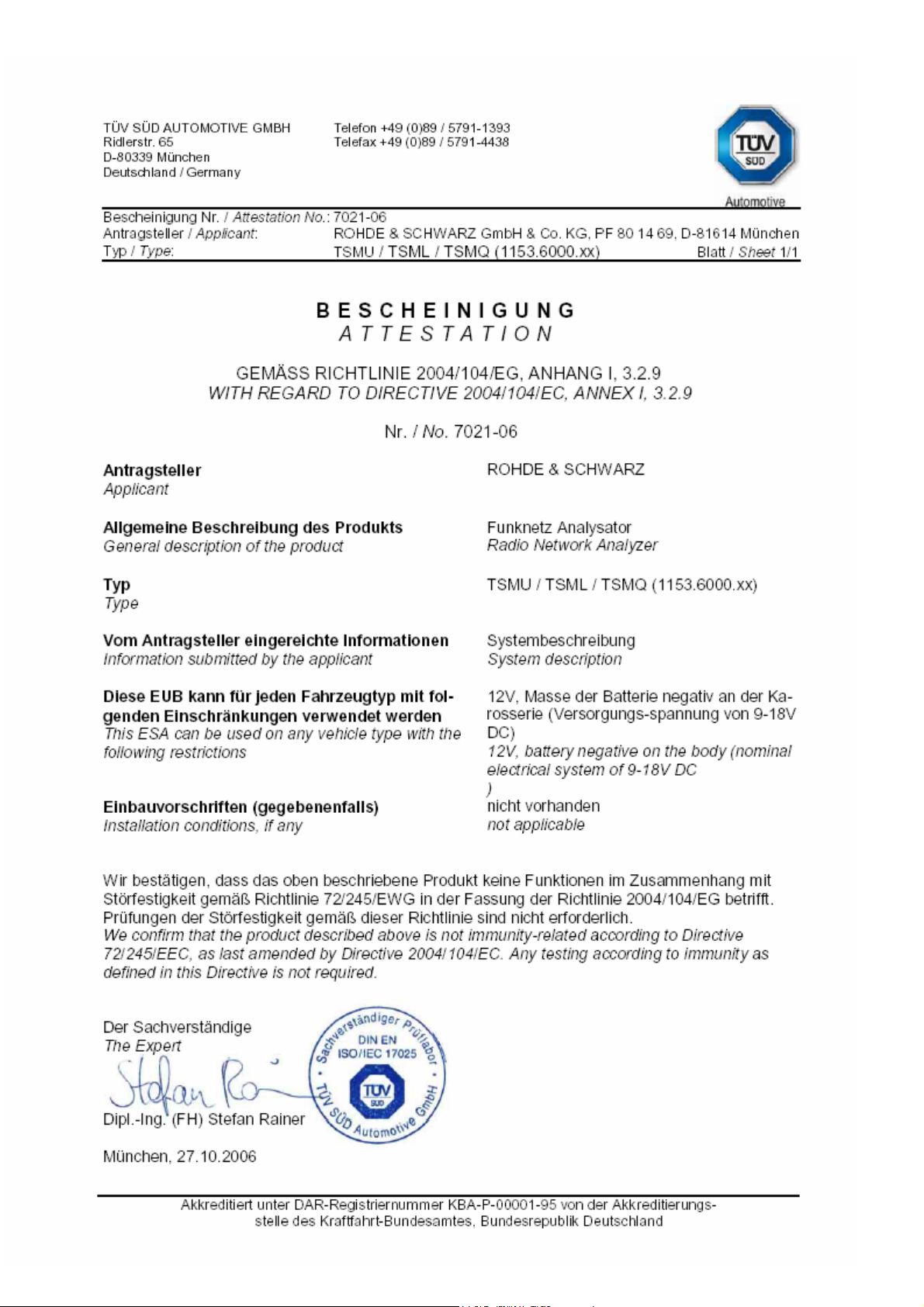
Attestation
Customer Support
Address List
Important Notes................................................................................................................................... 1
1 General Description...............................................................................................3
2 System Requirements ...........................................................................................5
3 Preparations for Use..............................................................................................7
Unpacking the Analyzer ...................................................................................................................... 7
TSMx IEEE 1394 Device Driver Installation........................................................................................ 7
Rack Mounting .................................................................................................................................... 7
4 Putting the Analyzer into Operation.....................................................................9
Prerequisites ....................................................................................................................................... 9
Connecting the External Devices ...................................................................................................... 10
Connecting the Analyzer to the Power Supply.................................................................................. 12
Power On Sequence/Idle Mode ........................................................................................................ 13
Initial Connection – Windows Device Driver Installation................................................................... 13
Application Program Download/Ready Mode ................................................................................... 15
Measuring Mode................................................................................................................................ 15
Analyzer Reset .................................................................................................................................. 15
Standby Mode ................................................................................................................................... 16
5 Firmware Updates................................................................................................17
Requirements .................................................................................................................................... 17
Program Start .................................................................................................................................... 17
6 Instrument Setup and Software Options............................................................19
Program Requirements ..................................................................................................................... 19
Program Start .................................................................................................................................... 19
Recalling Instrument Setup ............................................................................................................... 19
Recalling Enabled Firmware Options / Verifying Device Key Installation ......................................... 20
Reordering Firmware Options ........................................................................................................... 20
Post-Installation of Firmware Options ............................................................................................... 21
7 R&S ViCom Interface ...........................................................................................23
General.............................................................................................................................................. 23
Requirements .................................................................................................................................... 23
Installation ......................................................................................................................................... 23
1153.7494.12
I-1
Page 4

Contents R&S SML-x
8 Troubleshooting...................................................................................................25
Means of Error Detection .................................................................................................................. 25
Front Panel LEDs.................................................................................................................... 25
RS-232-C Output .................................................................................................................... 25
Troubleshooting Errors Indicated by Front Panel LEDs.................................................................... 26
Temperature Failure................................................................................................................ 26
Configuration State Failure ..................................................................................................... 26
Power Failure .......................................................................................................................... 26
Troubleshooting via the RS-232-C Interface..................................................................................... 27
Tracing Power On Sequence.................................................................................................. 27
Tracing Application Program Download and Ready Mode ..................................................... 28
Tracing Measuring Mode ........................................................................................................ 29
Problems after Firmware Update ...................................................................................................... 30
General ................................................................................................................................... 30
How to Solve the Configuration Problem Locally.................................................................... 30
1153.7494.12 I-2 E-4
Page 5

R&S TSML-x Important Notes
Important Notes
If you are using the R&S ViCom interface to control this R&S TSMx scanner, carefully follow all
instructions in the ViCom manual, located in the ..\doc subdirectory of the accompanying CD-ROM.
The latest ViCom version can be downloaded from the product homepage in the internet under:
http://www.rohde-schwarz.com
abbreviation R&S TSML is valid for all models in the series.
– Section Download/Software. Unless explicitly noted, the
Manuals
This manual describes how to put the analyzer into operation. Additional documentation and release
notes for the radio network analyzer are provided in the ..\doc section of the accompanying CD-ROM.
The ViCom programming interface for R&S TSMx analyzers is explained in detail with the ViCom
manual.
CD-ROM
The CD-ROM labeled R&S TSML Utilities, Interface and Documentation applies the following
directory structure:
- Documentation (Operating Manual, ViCom Manual ..\Doc
and Release Notes)
- Utility tool for firmware updates ..\TsmxFirmwareInstall
- Utility tool for recalling instrument setup and option key ..\TsmxOptionKeyInstaller
installation
- Utility tool for TSMx IEEE1394 device driver installation ..\IEEE1394
- Setup program for R&S ViCom programming interface ..\ViCom
- Backup copy of the instrument flash card contents ..\ACE_Files
Internet
The latest versions of all the related products data like Data Sheets, Application Notes, Application
Cards, Firmware, Software and Device Drivers could be downloaded from the product homepage in the
internet under: http://www.rohde-schwarz.com
.
Search for your analyzer type and select the menu item “DOWNLOADS”.
1153.7494.12 1 E-4
Page 6

Page 7

EC Certificate of Conformity
Certificate No.: 2009 - 48
This is to certify that:
Equipment type
Stock No. Designation
TSMU 1153.6000.02 Radio Network Analyzer
TSMU-H 1153.6000.03
TSML-W 1153.6000.11
TSML-C 1153.6000.12
TSML-G 1153.6000.13
TSML-CW 1153.6000.15
TSML-GW 1153.6000.20
TSMQ 1153.6000.50
complies with the provisions of the Directive of the Council of the European Union on the
approximation of the laws of the Member States
- relating to electromagnetic compatibility
(2004/108/EC)
Conformity is proven by compliance with the following standards:
EN 61326 – 1: 2006
EN 61326 – 2 – 1: 2006
EN 55011: 2007 + A2: 2007
For the assessment of electromagnetic compatibility, the limits of radio interference for Class
B equipment as well as the immunity to interference for operation in industry have been used
as a basis.
The product complies with the requirements of the Directive relating to the radio interference
of vehicles (72/245/EEC adapted by 2004/104/EC, 2005/49/EC, 2005/83/EC, 2006/28/EC,
after-market equipment in accordance with Annex I, paragraph 3.2.9 of the Directive); proof of
compliance provided by the measurements as described in Annex I, paragraphs 6.5, 6.6, 6.8,
6.9.
ROHDE & SCHWARZ GmbH & Co. KG
Mühldorfstr. 15, D-81671 München
Munich, 2009-09-22 Central Quality Management MF-QZ / Radde
E-1
Page 8

Page 9
Page 10

Internet R&S®TSML-x
1153.7494.12 2 E-4
Page 11

R&S TSML-x System Requirements
1 General Description
Using the radio network analyzer series R&S TSML always requires the availability of a host PC
software. The high speed link between the analyzer and the host PC software based on the IEEE
1394a standard.
There are two different possibilities for the host PC software to run and control the analyzer:
1. Applying the ready to use Drive Test Software Platform R&S ROMES (not part of this
package!)
2. Utilizing the R&S ViCom programming interface package and integrating this analyzer as
an OEM product into a customer specific software application.
In combination with the R&S ROMES software and depending on the model and enabled firmware
options, this radio network analyzer can be used as a powerful and budget-priced instrument for
interference analysis and network scanning in 2G and 3G networks or RF power and spectrum
measurements.
This R&S TSML analyzer also supports the ViCom interface. This software interface and a description
is part of the shipment. R&S ViCom interface is a C++ DLL based user interface designed for
customers who want to integrate this scanner into their own software application.
The following models of the analyzer are currently available:
R&S TSML-W Radio network analyzer for WCDMA networks
R&S TSML-C Radio network analyzer for CDMA/CDMA2000/1xEV-DO networks
R&S TSML-G Radio network analyzer for GSM networks
R&S TSML-CW Radio network analyzer for CW measurements
R&S TSML-GW Radio network analyzer for GSM / WCDMA measurements
(For details, refer to the R&S TSML data sheet and application notes.)
1153.7494.12 3 E-4
Page 12

Preparations for Use R&S TSML-x
1153.7494.12 4 E-4
Page 13

R&S TSML-x System Requirements
2 System Requirements
Controlling and accessing measurement data with the R&S TSML radio network analyzer series
requires the availability of a IEEE 1394 network adapter on the host PC.
IEEE 1394 interface requirements:
- OHCI chip set
- data rate 400 Mbit/s
- compliant with IEEE1394a-2000 standard
- compliant with OHCI 1.1 WHQL requirements
Operating system requirements:
- Windows XP SP2 or newer
Not mandatory for normal operation but very helpful for troubleshooting and servicing of the analyzer,
Rohde & Schwarz recommends the availability of a RS-232 interface on the host PC
(see Troubleshooting via the RS-232-C Interface).
1153.7494.12 5 E-4
Page 14

Preparations for Use R&S TSML-x
1153.7494.12 6 E-4
Page 15

R&S TSML-x System Requirements
3 Preparations for Use
Unpacking the Analyzer
The analyzer is shipped in a shipping box. Open the box, take the analyzer out of the box and make
sure that all items listed on the packing list are included.
If the analyzer or any included items are damaged, immediately notify the forwarder that shipped the
analyzer to you and keep the box and packing material.
For any future transport or shipment of the analyzer, the original shipping box should be used.
TSMx IEEE 1394 Device Driver Installation
Interfacing this R&S TSML radio network analyzer with the host PC software (R&S ROMES or R&S
ViCom) requires the installation of the appropriate IEEE 1394 TSMx device driver prior to initial
connection.
This TSMx 1394 device driver package is part of this shipment and located in the CD-ROM directory:
..\IEEE1394
The installer utility could be started directly from the CD-ROM by running the corresponding executable.
Refer to the Release Notes in the ..\doc subdirectory of the CD-ROM or search in the product
homepage under: http://www.rohde-schwarz.com
about this topic.
section Firmware/Download for detailed information
INFO
Device driver installation requires administrator privileges on the host PC!
Device driver installation needs to be done only once in a multi-TSMx environment,
where you connect more than one instrument to the same host PC.
Normally this device driver is already available with a valid R&S ROMES installation
of version 3NG or higher. So this step could be neglected but reinstallation does not
harm.
Rack Mounting
The receiver can be mounted in a 19” rack using the R&S TSMU-Z2 rack adapter in accordance with
the mounting instructions supplied. To obtain the ordering number, please contact your local
Rohde & Schwarz representative.
NOTICE
Danger of instrument damage!
Allow for sufficient air supply in the rack. Make sure that there is sufficient space
between the ventilation holes and the rack casing.
1153.7494.12 7 E-4
Page 16

Preparations for Use R&S TSML-x
1153.7494.12 8 E-4
Page 17

R&S TSML-x Putting the Analyzer into Operation
4 Putting the Analyzer into Operation
CAUTION Risk of injury and instrument damage
Handling and working with the instrument can cause injury to people or damage to
the instrument.
Make sure to follow the instructions in the following sections in order not to endanger
people and to avoid damage to the instrument
This is of particular importance when using the device for the first time. Also observe
the general Safety Instructions at the beginning of this manual.
Prerequisites
To operate the analyzer correctly, you need the following equipment and software installations:
• Host PC with IEEE1394 interface adapter 1394 network adapter is not part of the
R&S TSMx 1394 device driver installed package; (see “System Requirements
and TSMx IEEE 1394 Device Driver
Installation”)
• Antenna not part of the package (optional accessory)
• Connection cables partly part of the package;
(see Connecting the External Devices)
• DC power supply not part of the package:
(optional accessory R&S TSML-Z1/TSMU-Z1)
• R&S ROMES measurement software not part of the package
with appropriate TSMx license(s)
• Customer software application based on R&S ViCom interface and a test application is
R&S ViCom part of the package
(refer to the ViCom manual for installation
details)
• Optional: GPS unit which provides not part of the package
the pulse per second (PPS) output for optional accessory TSMx-PPS GPS Module
accurate time synchronization
EMI protective measures
To prevent electromagnetic interference, always operate the instrument when it is closed and with all
shielding covers installed. Only appropriate shielded signal and control cables may be used.
1153.7494.12 9 E-4
Page 18

Putting the Analyzer into Operation R&S TSML-x
Connecting the External Devices
Connect the IEEE 1394 port of the host PC to any of the IEEE1394 analyzer ports (1 or 2). Two
IEEE 1394 cables with different connector types for the host PC adapters are included in the
package.
More than one radio network analyzer could be connected to the host PC using the spare port of
the first analyzer and cascading additional analyzer(s) in a daisy chain topology!
Connect an RF antenna or signal generator input to the RF IN connector of the analyzer
(the antenna is not part of the package).
NOTICE
Connect the PPS output of the GPS device to the PULSE IN connector of the R&S TSML
(optional). (This will improve frequency accuracy).
Input type: 3.3 to 5 V TTL, max. +/-12 V DC; declaration of the high precision edge of the PPS
signal could be configured via software!
Optional: Additional multifunctional input/output connector PULSE IN/OUT. Used e.g. as distance
trigger input (only used for distance triggered RF power scan measurements, R&S TSMU-KK35).
Input type: max +/- 12 V DC
Optional: The RS232 connector should be connected with the RS-232-C interface of the host PC
via a null-modem cable (for service purposes and troubleshooting; see Troubleshooting).
Finally, connect the R&S TSML to the power supply
Not mandatory for normal operation but very helpful for troubleshooting and servicing of the
analyzer, Rohde & Schwarz recommends the availability of a RS-232 interface on the host PC
(see Troubleshooting via the RS-232-C Interface).
See Fig. 2 for the complete wiring diagram.
Danger of instrument damage!
Do not to inject more than the maximum rated RF input power. Otherwise, the input
stage could be severely damaged.
R&S TSML: -10 dBm
Fig. 1 R&S TSML rear panel with connectors
1153.7494.12 10 E-4
Page 19

R&S TSML-x Putting the Analyzer into Operation
IEEE1394
Null-m
odem
Power cable
blue cord: negative)
Power cable
Optional:
GPS
PPS
receiver
(optional)
distance trigger input
for CW measurements
(R&S TSML-CW only)
Accessories and cables
that are not part of the
standard delivery
PPS: Pulse per Second,
falling edge with high precision!
GPS: Global Positioning System
BNC cable
6/6 pin
or 6/4 pin
cable
Antenna
RF IN
R&S TSML
PULSE IN
PULSE
IN/OUT
IEEE1394-1/2 RS232
IEEE1394 RS-232-C
DC IN
9-pin cable
(serial interface
optional)
Notebook/PC
The R&S TSML can be
powered from any of these
three sources:
TSML-Z1
Customer
**
DC power
supply
9 V to 18 V
1.2 A/13.5 V
12 V vehicle
lighter
receptacle
*
(comes with the DC power supply)
** Power cable
(2-pin power jack dismounted
and wires connected directly with
customer power supply;
brown cord : positive
***
(car adapter connected at the
2-pin power connector; positive
voltage at the center of the
receptacle)
1153.7494.12 11 E-4
Fig. 2 Wiring diagram
Page 20

Putting the Analyzer into Operation R&S TSML-x
Connecting the Analyzer to the Power Supply
The RS232 connector should be connected with the RS-232-C interface of the
ANGER
D
f the
NOTICE
Danger of shock hazard!
- After moisture condensation, allow the receiver to dry before switching on.
with the power button but still connected with the DC Power Supply.
- After connecting the Power Supply the device is immediately under power.
- The DC-Connector is intended for disconnection.
If another DC Supply than TSML-Z1 is used:
Danger of instrument damage!
- Do not cover the ventilation holes.
- Connect the receiver only with SELV (Safety Extra Low Voltage) power
supplies.
- An additional external fuse must be inserted if the DC power supply offers more
than 35 A!
- Use only EN 60950 approved external DC power supplies
- The receiver may be connected only to DC supplies:
The device is still power-supplied while it is in Standby Mode i.e. switched off
a) Customer DC-Supply shall be in accordance with IEC / EN / UL / CSA
60950-1 or IEC / EN / UL / CSA EN EN61010-1.
b) 12 V vehicle cigarette lighter socked must be fused.
DC Input range: 9 V to 18 V with 10A max
DC input current: ~ 700 mA / 13.5 V
NOTICE
Rohde & Schwarz offers a compatible power supply, the R&S TSML-Z1. To obtain the ordering number,
please contact your local Rohde & Schwarz representative.
EMI Protective Measures!
- Do not use DC and IEEE1394 cables longer than 3 m
- No operation at DC mains excluded vehicle mains.
1153.7494.12 12 E-4
Page 21

R&S TSML-x Putting the Analyzer into Operation
Power On Sequence/Idle Mode
On applying DC power the analyzer enters power on mode and passes the power on sequence and
boot loop. The self test during the power on sequence initiates various reboot cycles.
The power on sequence can be monitored by means of the front-panel LEDs (see Fig. 4 for LED
location). Additional information will be output via the RS-232-C interface (see Tracing Power On
Sequence).
LED Color State Comment
PWR Green On Continuously after power on
CONFIG STATE
PROCESS STATE Green Off Continuously after power on
PROCESS RUN Green Off Continuously after power on
Amber On
Off
On
About a second after PWR LED goes on
With each reboot cycle during initialization
Continuously after completion of initialization
Fig. 3 Front-panel LEDs during power on sequence
Connecting a certain R&S TSML analyzer for the first time to a host PC initiates Windows device driver
installation (see Initial Connection – Windows Device Driver Installation).
Radio network analyzers which once successfully passed Windows device driver installation directly
enter the idle mode. In idle mode the analyzer is ready for being interfaced with the host PC software.
(see Tracing Power On Sequence).
Initial Connection – Windows Device Driver Installation
The Windows “Found new Hardware dialog” pops up as soon as you connect an R&S TSMÖ analyzer
for the first time to a certain host PC and Windows asks for the pleasant device driver. Select “Install
software automatically” and complete Windows device driver installation.
Requirement: TSMx device driver installation prior to connection (see TSMx IEEE 1394 Device Driver
Installation)!
The radio network analyzer enters idle mode after completion of the Windows device driver installation.
In idle mode the analyzer is ready for being interfaced with the host PC software. (see Application
Program Download/Ready Mode).
1153.7494.12 13 E-4
Page 22

Putting the Analyzer into Operation R&S TSML-x
Fig. 4 R&S TSML front panel and LEDs
1153.7494.12 14 E-4
Page 23

R&S TSML-x Putting the Analyzer into Operation
Application Program Download/Ready Mode
Entering idle mode (see Power On Sequence/Idle Mode) the R&S TSML analyzer is ready to be
interfaced from the host PC software (R&S ROMES respectively R&S ViCom).
While loading the TSML software driver or workspace in R&S ROMES software the application program
(*.elf) will be downloaded from the host and the availability of pleasant instrument options will be
checked.
Similarly the program download and option check will be executed while calling the LoadTSMx function
in the R&S ViCom interface.
Please refer to the corresponding R&S ROMES respectively ViCom manuals for details on this matters.
The analyzer changes to the ready mode after receiving the application program from the host. The
instrument is now ready for ROMES or ViCom originated measurement tasks.
The ready mode is indicated by the front-panel LEDs: The green PROCESS LEDs STATE and RUN
start blinking alternately (see Tracing Application Program Download and Ready Mode).
Measuring Mode
The unit changes into the measuring mode after receiving a “Start Measurement/Recording” command.
For information on how to carry out R&S TSML measurements with R&S ROMES software or with R&S
ViCom interface, please refer to the corresponding manuals.
There is no change in LED indication on the front panel. The green PROCESS LEDs STATE and RUN
continue blinking alternately (see Tracing Measuring Mode).
Analyzer Reset
Unloading the R&S TSML software driver in ROMES, closing ROMES software or unloading the
R&S TSMx module in the R&S ViCom interface initiates an analyzer reset. After the reset had been
completed, the R&S TSML analyzer passes power-on sequence and enters the idle mode again (see
Power On Sequence/Idle Mode). The R&S TSML is now ready for a new application program
download.
Pressing the reset button on the front panel also initiates an analyzer reset cycle.
NOTICE Danger of software crash
Do not press the reset button during ordinary R&S TSML measurements with the R&S
ROMES software or R&S ViCom interface. Otherwise, it could happen that the host PC
software is not closed properly. As a result, the application will crash and must be shut
down from the Windows Task Manager.
1153.7494.12 15 E-4
Page 24

Putting the Analyzer into Operation R&S TSML-x
Standby Mode
You can switch the R&S TSML analyzer into the standby mode by pressing the POWER button on the
front panel (see Fig. 4). In the standby mode, the program execution on the R&S TSML will be stopped
immediately and the unit will be powered off.
The amber STBY LED on the front panel indicates the standby mode.
NOTICE Danger of measurement disruption
Do not press the power button ongoing R&S TSML measurements with the R&S
Pressing the POWER button in the standby mode initiates power-on sequence again (see Power On
Sequence/Idle Mode).
ROMES software or R&S ViCom interface!
1153.7494.12 16 E-4
Page 25

R&S TSML-x Firmware Updates
5 Firmware Updates
For firmware updates the TsmxFirmwareInstall utility tool will be provided. The latest version of the
utility including the current firmware file could be downloaded from the product homepage in the internet
under: http://www.rohde-schwarz.com
Search for your analyzer type and select the menu item “DOWNLOADS” –> “FIRMWARE”.
This tool is interactive and guides you through the entire firmware update process.
.
NOTICE
Danger of instrument damage!
Make sure that neither ROMES nor any other utility tool interfaces with the TSML at the
same time. Shut down any active utility before starting the TsmxFirmwareInstall tool!
Requirements
• PC/Notebook with IEEE1394 interface adapter and R&S TSML analyzer connected.
• R&S TSMx IEEE 1394 driver installed on the host PC.
• RS-232 interface (COM1) of PC/notebook and R&S TSML connected via a null-modem cable
(see RS-232-C Output for terminal settings).
• R&S TSML powered up and power on sequence completed successfully (see Power On
Sequence/Idle Mode).
• No other application interfacing with the R&S TSML.
Program Start
Reset the R&S TSML analyzer and start the utility by running the TsmxFirmwareInstall.exe in the
program directory. Any of the available firmware versions located in the program subfolder ..\Firmware,
can be selected from a dialog box during program execution.
1153.7494.12 17 E-4
Page 26

Putting the Analyzer into Operation R&S TSML-x
1153.7494.12 18 E-4
Page 27

R&S TSML-x Instrument Setup and Software Option
6 Instrument Setup and Software Options
The TsmxOptionKeyInstaller utility tool is used to recall the instrument setup and to install new
firmware options. This tool is located on the accompanying CD-ROM respectively could be downloaded
from the internet under: http://www.rohde-schwarz.com
Search for your analyzer type and select the menu item “DOWNLOADS” –> “SOFTWARE”.
Program Requirements
• PC/Notebook with IEEE1394 interface adapter and R&S TSML analyzer connected
(It is possible to connect more than one analyzer in a daisy chain topology!).
• R&S TSMx IEEE 1394 driver installed on the host PC
• RS-232 interface (COM1) of PC/notebook and R&S TSML connected via a null-modem cable
(see RS-232-C Output for terminal settings).
• R&S TSML powered up and power on sequence completed successfully (see Power On
Sequence/Idle Mode).
• No other software application interfacing with the R&S TSML
.
Program Start
The utility will be started by running the OptionKeyInstaller.exe in the program directory. The program
needs a few seconds to set up the connection with all the connected R&S TSML device(s). All
analyzers start indicating “ready mode” after a while.
The instrument-related data for a certain analyzer will be displayed as soon as the connection is
established.
If there is more than one instrument connected use the combo box “Select TSMx” to select the desired
analyzer by choosing the appropriate serial number.
Recalling Instrument Setup
Select the R&S TSMx Info property page. This page displays all the related instrument data.
• Hardware State
• Serial Numbers
• Firmware Version
• Calibration Data
1153.7494.12 19 E-4
Page 28

Instrument Setup and Software Option R&S TSML-x
Recalling Enabled Firmware Options / Verifying Device Key Installation
Select the “TSMx Options” property page. To address a certain analyzer select the appropriate serial
number in the “Select TSMx” combo box for that purpose.
The text “The Device Key is installed” is output in this program dialog, if a valid device key is installed
for a certain instrument.
A missing device key will be output with “No Device Key has been found” in the program dialog.
A valid device key installation is mandatory for ordering additional firmware options.
A list box displays the available firmware options for a certain analyzer.
INFO
Customers with missing device key installation on their R&S TSML analyzer are kindly
asked to get in contact with their local R&S representatives to update their instrument
with the latest version of option licensing.
Reordering Firmware Options
Reordering firmware options require solely the supplement of the device serial number when placing
the option order.
Only in cases where no device key is installed for a certain analyzer (see Recalling Enabled Firmware
Options / Verifying Device Key Installation) the device specific identification file (*.hex) is mandatory
for generating the option license files at Rohde & Schwarz.
In such cases press the button “Get Device ID File...” in the “TSMx Options” tab to read out the device
identification file. A dialog box opens to define the storage location for this file.
Attach this ID file with the firmware option order.
INFO
Reordering additional firmware options for a R&S TSML analyzer types is not supported
as this kind of analyzers is shipped with a fixed and dedicated set of firmware options.
1153.7494.12 20 E-4
Page 29

R&S TSML-x R&S ViCom Interface
Post-Installation of Firmware Options
Reordered firmware options are shipped as license files on a separate CD-ROM or could be
ownloaded from the company web server (http://cms.rohde-schwarz.com/options
d
installed by the customer using the TsmxOptionKeyInstaller utility.
.
INFO
Only reordered firmware options need to be installed in a post process. Shipped
analyzers are already equipped with pre-installed firmware options. z
and need to be
)
INFO
Please refer to the SWInstallationManual_xxx.pdf and the FWReleaseNote_xxx.pdf in the ..\doc
subdirectory of the CD-ROM for details on how to proceed.
xxx: Version info string
Reordering additional firmware options for a R&S TSML analyzer types is not supported
as this kind of analyzers is shipped with a fixed and dedicated set of firmware options.
1153.7494.12 21 E-4
Page 30

Instrument Setup and Software Option R&S TSML-x
1153.7494.12 22 E-4
Page 31

R&S TSML-x R&S ViCom Interface
7 R&S ViCom Interface
General
R&S ViCom interface is a software package designed planning to develop their own software
applications and integrating the R&S TSML analyzer as an OEM product into their product.
The R&S ViCom package, which is part of this shipment, need to be installed on the host PC and
includes documentation and sample applications.
INFO
Interfacing the R&S TSML analyzers via the R&S ViCom interface generally requires
the availability of dedicated OEM firmware options (R&STSMU-K3x) on the instrument.
Per default the R&S TSMQ and R&S TSML analyzers are equipped with a fixed set of
OEM firmware options whereas these OEM firmware options for the R&S TSMU / R&S
TSMU-H analyzers need to be installed seperately.
Please ask your local R&S representative for questions on this matter.
Requirements
• Dedicated OEM option(s) R&S TSMU-K3x installed on the instrument (see Recalling Enabled
Firmware Options / Verifying Device Key Installation).
• R&S ViCom software interface package installed on the host PC
• Firmware version from 10.24 (see Recalling Instrument Setup).
• R&S TSMx 1394 device driver installed on the host PC.
Installation
The setup program including sample applications and documentation is shipped with the CD-ROM and
is located in the subdirectory ..\ViCom.
The latest ViCom version could be downloaded from the product homepage in the internet under:
http://www.rohde-schwarz.com
INFO
1153.7494.12 23 E-4
If there is already an existing R&S ViCom installation on the host PC this version need
to be uninstalled first (Start->Settings->Add and Remove Programs) before the R&S
ViCom setup program can be started.
– Section Download/Software.
Page 32

Instrument Setup and Software Option R&S TSML-x
1153.7494.12 24 E-4
Page 33

R&S TSML-x Troubleshooting
8 Troubleshooting
Means of Error Detection
Front Panel LEDs
The following LEDs on the front panel indicate an error (see Fig. 4):
ERROR TEMP: red - lit: Temperature Failure
Temperature inside the device is too high.
CONFIG STATE ERR: Configuration State Failure
red - flash: No flash card inserted in flash card slot.
lit: Data on flash card is invalid or program error.
ERROR PWR: red - lit: Power Failure
At least one internal voltage rail is out of tolerance.
RS-232-C Output
During startup and normal operation, the R&S TSML outputs status information via the RS-232-C
connector on the rear panel parallel with standard communication via the IEEE1394 interface.
Monitoring the output information on the serial interface does not decrease the analyzer's performance
in any manner, but is always a valuable tool to verify the analyzer's current state.
To display the status information on the computer, the following steps are necessary:
Connect a serial 9-pin null modem cable between the RS-232-C socket of the analyzer and the
serial interface of your PC.
• Set up a terminal program connection on your computer’s RS-232-C interface with the following
settings:
Bits per second: 115200
Data bits: 8
Parity: no parity
Stop bit: 1
Flow control: no flow control
• Start the terminal session.
1153.7494.12 25 E-4
Page 34

Troubleshooting R&S TSML-x
Troubleshooting Errors Indicated by Front Panel LEDs
Temperature Failure
The electronic equipment in the radio network analyzer is protected against thermal destruction. If the
temperature inside the analyzer exceeds a specific limit, the unit changes to the TEMP ERROR mode
and switches off the main voltages.
To switch the unit to standby mode, press the POWER button.
If the temperature error occurs repeatedly within the operating temperature range, return the device to
Rohde & Schwarz service.
Configuration State Failure
Both, FPGA configuration data and the boot code are read from the internal compact flash (CF) card
during power on sequence.
CONFIG ERR LED (LED blinking): indicates No Flash Card Inserted
-> the configuration data cannot be read from the CF card.
Switch off the instrument, remove the CF card and check whether the card could be read on a Windows
PC with Flash Card Reader or PCMCIA slot (PCMCIA adapter is needed!). The directory structure on
the card and its contents should be the same as in ..\ACE Files on the accompanying CD-ROM.
To access the CF card, remove the small metal plate at the rear panel labeled with SMART CARD by
loosening the screws and pull it out of the slot.
If the flash card is detected correctly in the PC and the file structure is identical, push the CF card into
the slot and power on the instrument again.
In the event of a repeated error or a card-read error on the PC, contact Rohde & Schwarz support.
CONFIG ERR LED (LED illuminated, during the power-on sequence): indicates Flash Card Error
-> the flash card may contain erroneous or corrupt files.
Remove the CF card from the instrument and insert it in a Flash Card Reader or PCMCIA slot
(a PCMCIA adapter is needed) on your PC. Check the directory and file structure on the card. It should
be the same as in ...\ACE Files on the accompanying CD-ROM.
With this information in hand plus the instrument's serial number read from the label on the rear panel,
contact Rohde & Schwarz support.
CONFIG ERR LED (LED illuminated while ordinary ROMES / ViCom applications): indicates Program
Failure on the analyzer
-> at this stage, the instrument won’t no longer respond to any software command. This could be
checked by monitoring the RS-232-C output (see Tracing Measuring Mode) and the PROCESS LEDs
on the front panel (see Measuring Mode). The blinking of the front panel LEDs signaling measurement
mode will be frozen.
In this case, end the task of the controlling software application from the Windows Task Manager and
reset the R&S TSML analyzer. Wait for the instrument to complete the power on sequence and initiate a
new measurement session.
If the error persists, contact Rohde & Schwarz support.
Power Failure
At least one internal voltage rail is out of range. Return the device to Rohde & Schwarz service.
1153.7494.12 26 E-4
Page 35

R&S TSML-x Troubleshooting
Troubleshooting via the RS-232-C Interface
Monitor the status information output on the serial interface (see Troubleshooting via the RS-232-C
Interface) to check whether the instrument is functioning properly.
Tracing Power On Sequence
Press the reset button on the front panel. If the unit is in standby mode, press the power button. In both
cases, the following listing should appear on the "Hyper Terminal" screen (see Listing 1):
NOTICE Danger of instrument damage!
Be sure that no software application on the host PC is connected with the instrument for
this test.
Pipelined Version of DSOCM.
-----------------
Tsmu Boot Stage 0
dwTag >> 16 = 0000065503
ÿÿ
dwTag >> 16 = 0000065535
ÿ
Pipelined Version of DSOCM.
Pipelined Version of DSOCM.
---
---
----------------------------
TSMx BOOT STAGE 1 V.11020000
built: Tue Nov 28 19:22:25 GMT 2006
Performance Test 169 137 119
M_Pci.ChipInfo.u8RevisionId=00000061
dwPciReg24=0090b801
dwPciReg28=00bdbbab
PCI chip Revision ID = 0x61
SerialNumberVerify(TRUE)=1
M_Mt.bFirmwareMajor=0000000b
M_Mt.wFirmwareMinor=00000002
Firmware 11.0002
M_Mt.dwSoftwareVersion=11020000
Tue Nov 28 19:24:56 2006
forcing bus reset
IRQ busReset, dwNodeID=0xc000ffc1
busReset packet, dwNodeID=0xc000ffc1, dwSelfIDGeneration=1
IRQ busReset, dwNodeID=0x8000ffc0
busReset packet, dwNodeID=0x8000ffc0, dwSelfIDGeneration=2
Listing 1 Terminal output during power on sequence
If the output corresponds with Listing 1 where the number of IRQ bus resets at the end of the output
can vary the network analyzer completed the power on sequence and is ready for the application
program download via the IEEE1394 interface.
In the event of no output string, check the "Hyper Terminal" settings and the connection cabling and
reset the instrument.
If the error persists or the output end with “…
bus reset not possible, contact Rohde & Schwarz support.
1153.7494.12 27 E-4
Page 36

Troubleshooting R&S TSML-x
on the RF input
Tracing Application Program Download and Ready Mode
he R&S TSML application program will be downloaded from the host PC either during ROMES driver
T
configuration or while calling the LoadTsmx function of the ViCom interface. (refer to the ROMES
respectively ViCom manual for details).
After program download, the radio network analyzer will start some initialization routines. Finally the
receiver will enter ready mode. Any measurement from ROMES / ViCom software or ViCom could be
initiated at this point. Please refer to the ROMES or ViCom manual for details.
In idle mode and depending on the availability of a valid PPS input signal on the PULSE IN connector
respectively a GSM input signal on the RF antenna, the receiver will start to correct the internal system
clock. An output like shown in Listing 2 should appear at the terminal log.
m_dwPostofficeProtocolNumber=3
Tx packet size = 2048
PostOfficeState set to 1
Pipelined Version of DSOCM.
Start of Program StarterPipelined Version of DSOCM.
----------------------------
TSMx MEASUREMENT APPLICATION V.11020000
built: Tue Nov 28 19:25:12 GMT 2006
M_Pci.ChipInfo.u8RevisionId=00000061
---
SerialNumberVerify(TRUE)=1
M_Mt.bFirmwareMajor=0000000b
M_Mt.wFirmwareMinor=00000002
Firmware 11.0002
M_Mt.dwSoftwareVersion=11020000
Tue Nov 28 19:26:30 2006
M_Rec.bDeviceVariantNumber=11
FE Temperature = 47°
UMTS Filter Implemented
M_Rec.FstrTsmuData.st_LevelCal & VALID=1
M_Rec.FstrTsmuData.st_IFFilterMeas & VALID=1
M_Rec.FstrTsmuData.st_UMTSFilter & VALID=1
TSMx ADC Phase Shift adjusted to 37%. Window 89%, Error Level = 22%
forcing bus reset
IRQ busReset, dwNodeID=0x8000ffc0
busReset packet, dwNodeID=0x8000ffc0, dwSelfIDGeneration=20
---
IRQ busReset, dwNodeID=0x8000ffc0
busReset packet, dwNodeID=0x8000ffc0, dwSelfIDGeneration=21
m_dwPostofficeProtocolNumber=3
Tx packet size = 2048
PostOfficeState set to 1
FPGA Configuration:
H01V10B0
Fri Nov 5 10:34:56 2004
FPGA Configuration:
H01V10B0
Fri Nov 5 10:34:56 2004
GSM TCXO Correction (-512 to +511) = -25
GSM TCXO Correction (-512 to +511) = -23
"GSM900 / GSM1800 used for GSM Synchronisation."
GSM TCXO Correction (-512 to +511) = -25
GSM TCXO Correction (-512 to +511) = -24
GSM TCXO Correction (-512 to +511) = -25
GSM TCXO Correction (-512 to +511) = -25
GSM TCXO Correction (-512 to +511) = -24
GSM TCXO Correction (-512 to +511) = -26
Initialization
sequence
Synchronization
~ 1 output line/sec
Only if a GSM
signal is available
connector!
Listing 2 Terminal output during program download and in the ready mode
1153.7494.12 28 E-4
Page 37

R&S TSML-x Troubleshooting
Tracing Measuring Mode
tarting measurement/recording in the R&S ROMES software respectively launching a measurement
S
command with the R&S ViCom interface initiates a new measurement task at the analyzer. The
instrument switches from ready mode to measuring mode.
Stopping measurement/recording in the R&S ROMES software or with the R&S ViCom interface
switches the unit back to ready mode.
Please refer to the R&S ROMES or R&S ViCom manual for details.
Output like shown in Listing 3 should appear on the terminal program screen.
---
PPS TCXO Correction (-512 to +511) = -24
"Start Frame Arrived"
"Start Frame Arrived"
GSM TCXO Correction (-512 to +511) = -23
PPS TCXO Correction (-512 to +511) = -24
PPS TCXO Correction (-512 to +511) = -24
PPS TCXO Correction (-512 to +511) = -24
PPS TCXO Correction (-512 to +511) = -24
PPS TCXO Correction (-512 to +511) = -24
---
---
PPS TCXO Correction (-512 to +511) = -24
PPS TCXO Correction (-512 to +511) = -24
PPS TCXO Correction (-512 to +511) = -24
PPS TCXO Correction (-512 to +511) = -24
PPS TCXO Correction (-512 to +511) = -24
PPS TCXO Correction (-512 to +511) = -24
PPS TCXO Correction (-512 to +511) = -24
StopMeasFrameArrived
PPS TCXO Correction (-512 to +511) = -24
PPS TCXO Correction (-512 to +511) = -24
---
---
“Start
Measurement/
Recording”
“Stop
Measurement/
Recording”
Listing 3 Terminal output in measuring mode
1153.7494.12 29 E-4
Page 38

Troubleshooting R&S TSML-x
Problems after Firmware Update
General
Under certain cases the radio network analyzer will not boot after a firmware update, and the CONFIG
LED on the front panel indicate an error.
The cause is usually a wrong setting of the configuration directory on the compact flash card of the
device while executing firmware update.
In such a case, this mal function could be solved by the customer by editing the ini-file of the analyzer
flash card on a PC with flash card slot.
How to Solve the Configuration Problem Locally
Remove power supply from the analyzer and pull out the flash card from the instrument. The flash card
is accessible from the rear panel by loosing four screws of the metal plate cover named “SMART
CARD”. Remove this plate.
Insert the card in the PC card reader or PCMCIA slot of a PC/notebook.
Open the xilinx.sys file in the root of the flash card with an editor and change the dir variable according
to the following table:
Before modification After modification
dir = H01V10B0; dir = H00V10B0;
dir = H00V10B0; dir = H01V10B0;
Insert the edited flash card into the radio network analyzer again and connect it with the power supply
again. The unit should now pass boot sequence correctly. If this failure persists, contact Rohde &
Schwarz support.
Background: Two separate configuration directories are located on the flash card of each instrument
(H01V10B0 and H00V10B0). The xilinx.sys file in the root directory defines which one is the bootable
directory.
Different configuration directories are necessary, because of two different versions of the printed circuit
board (PCB) inside the R&S TSML. In some cases after firmware update, the incorrect configuration
directory may be activated which doesn’t comply with the PCB board version.
1153.7494.12 30 E-4
 Loading...