

Page 1
R&S®TSME6
Ultracompact Drive Test Scanner
User Manual
(a00Q2)
4900003302
User Manual
Version 04
Page 2

This manual applies to the following R&S®TSME6 models and options:
●
R&S®TSME6 (4900.0004.02)
●
Block IQ Option R&S®TSME6-K10 (4900.2459.02)
●
TD-SCDMA Option R&S®TSME6-K20 (4900.2220.02)
●
WCDMA Scanner Option R&S®TSME6-K21 (4900.2188.02)
●
CDMA2000® Option R&S®TSME6-K22 (4900.2165.02)
●
GSM Scanner Option R&S®TSME6-K23 (4900.2194.02)
●
1xEVDO Rev. A Scanner Option R&S®TSME6-K24 (4900.2142.02)
●
CW Scanner Option R&S®TSME6-K25 (4900.2242.02)
●
TETRA Scanner Option R&S®TSME6-K26 (4900.2142.02)
●
RF Power Scan Option R&S®TSME6-K27 (4900.2120.02)
●
WiMAX™ Scanner Option R&S®TSME6-K28 (4900.2136.02)
●
LTE Scanner Option R&S®TSME6-K29 (4900.2171.02)
●
LTE MIMO 2x2, 4x2, 4x4 R&S®TSME6-K30 (4900.2113.02)
●
LTE eMBMS Option R&S®TSME6-K32 (4900.2288.02)
●
NB-IoT/Cat NB1 Scanning R&S®TSME6-K34 (4900.2207.02)
●
LTE M Option R&S®TSME6-K35 (4900.2465.02)
●
Automatic Channel Detection R&S®TSME6-K40 (4900.2259.02)
●
5G NR Scanning Option R&S®TSME6-K50 (4900.2436.02)
●
BTS PE Enabler R&S®TSME6-K80 (4900.2442.02)
© 2020 Rohde & Schwarz GmbH & Co. KG
Mühldorfstr. 15, 81671 München, Germany
Phone: +49 89 41 29 - 0
Fax: +49 89 41 29 12 164
Email: info@rohde-schwarz.com
Internet: www.rohde-schwarz.com
Subject to change – Data without tolerance limits is not binding.
R&S® is a registered trademark of Rohde & Schwarz GmbH & Co. KG.
Trade names are trademarks of the owners.
4900.0033.02 | Version 04 | R&S®TSME6
Throughout this manual, products from Rohde & Schwarz are indicated without the ® symbol , e.g. R&S®TSME6 is indicated as
R&S TSME6.
Page 3

R&S®TSME6
1.1.1 Getting Started Manual................................................................................................... 5
1.1.2 User Manuals and Help...................................................................................................5
1.1.3 Tutorials...........................................................................................................................5
1.1.4 Basic Safety Instructions.................................................................................................5
1.1.5 Brochures........................................................................................................................5
1.1.6 Application Notes, Application Cards, White Papers, etc................................................6
1.2.1 Korea Certification Class B............................................................................................. 6
Contents
Contents
1 Preface.................................................................................................... 5
1.1 Documentation Overview............................................................................................. 5
1.2 Safety and Regulatory Information............................................................................. 6
2 Key Features...........................................................................................7
3 Instrument Tour......................................................................................8
3.1 Front Panel View........................................................................................................... 8
3.2 Rear Panel View.............................................................................................................9
4 Option Concept.................................................................................... 12
4.1 Technology Options....................................................................................................12
4.2 Band Options...............................................................................................................13
4.3 Option Sharing Concept.............................................................................................13
5 Preparing for Use.................................................................................15
5.1 Putting into Operation................................................................................................ 15
5.1.1 Unpacking and Checking the Instrument...................................................................... 16
5.1.2 Accessory List............................................................................................................... 17
5.1.3 Cascading R&S TSME6s.............................................................................................. 17
5.1.4 Connecting the DC Power Supply.................................................................................20
5.1.5 Setting Up the LAN Connection to the Host PC............................................................22
5.1.5.1 Configuring the LAN Interface on the Host PC............................................................. 23
5.1.5.2 Firewall Configuration................................................................................................... 26
5.1.5.3 Connecting the R&S TSME6 to the Host PC................................................................ 27
5.1.6 Connecting External Devices........................................................................................ 27
5.1.7 Connecting a Kensington Lock..................................................................................... 28
3User Manual 4900.0033.02 ─ 04
Page 4

R&S®TSME6
5.1.8 Enabling Untethered Dead Reckoning .........................................................................28
5.2.1 Using Two R&S TSME6s in Parallel............................................................................. 29
5.2.2 LTE MIMO Setups with Two R&S TSME6s...................................................................30
5.2.3 LTE MIMO Setups with Four R&S TSME6s..................................................................32
6.1.1 Obtaining Device Information - "Device Info"................................................................ 40
6.1.2 Changing IP Addresses - "Network Configuration"....................................................... 43
6.1.3 Installing and Managing Software License Keys - "Options"........................................ 44
Contents
5.2 Connecting Multiple R&S TSME6s to One Host PC.................................................29
5.3 Switching the Instrument On and Off........................................................................35
5.4 Connecting the R&S TSME6 to a Software Application for the First Time............35
6 Configuring the R&S TSME6...............................................................39
6.1 Using the R&S TSME Device Manager......................................................................39
6.1.4 Configuring Measurement Bands - "Band Configuration"............................................. 46
6.1.5 Obtaining Firmware and Correction Data Updates - "Updates".................................... 48
6.1.6 Aligning R&S TSME6 Manually - "Self Alignment"........................................................49
6.1.7 Configuring Downconverter R&S TSME30DC/TSME44DC - "Downconverter Configu-
ration"............................................................................................................................ 50
6.2 Interacting with R&S ROMES, R&S NESTOR, and R&S ViCom..............................52
6.2.1 Interacting with R&S ROMES....................................................................................... 52
6.2.2 Interacting with R&S NESTOR......................................................................................53
6.2.3 Interacting with R&S ViCom..........................................................................................53
7 Troubleshooting................................................................................... 55
7.1 Guide to Solve Instrument Connection Problems................................................... 55
7.2 Solving Other Miscellaneous Problems....................................................................58
7.3 Contacting Customer Support...................................................................................60
Annex.................................................................................................... 62
A Available Cellular Bands..................................................................... 62
Index......................................................................................................69
4User Manual 4900.0033.02 ─ 04
Page 5

R&S®TSME6
1.1 Documentation Overview
1.1.1 Getting Started Manual
Preface
Documentation Overview
1 Preface
This section provides an overview of the R&S TSME6 user documentation. Unless
specified otherwise, you find the documents on the R&S TSME6 product page at:
www.rohde-schwarz.com/manual/tsme6
Introduces the R&S TSME6 and describes how to set up and start working with the
product. Includes basic operations, typical measurement examples, and general information, e.g. safety instructions, etc. A printed version is delivered with the instrument.
1.1.2 User Manuals and Help
Contains the description of all instrument modes and functions. It also provides information on maintenance, instrument interfaces and error messages. Includes the contents of the getting started manual .
1.1.3 Tutorials
Tutorials offer guided examples and demonstrations on operating the R&S TSME6.
They are provided on the internet page of the product.
1.1.4 Basic Safety Instructions
Contains safety instructions, operating conditions and further important information.
The printed document is delivered with the instrument.
1.1.5 Brochures
The brochure provides an overview of the instrument and deals with the specific characteristics and contains the technical specifications of the R&S TSME6. It also lists the
firmware applications and their order numbers, and optional accessories.
See www.rohde-schwarz.com/brochure-datasheet/tsmx
5User Manual 4900.0033.02 ─ 04
Page 6

R&S®TSME6
1.1.6 Application Notes, Application Cards, White Papers, etc.
1.2 Safety and Regulatory Information
Preface
Safety and Regulatory Information
These documents deal with special applications or background information on particular topics.
See www.rohde-schwarz.com/application/tsmx
The product documentation helps you use the R&S TSME6 safely and efficiently. Follow the instructions provided here and in the printed "Basic Safety Instructions". Keep
the product documentation nearby and offer it to other users.
Intended use
The R&S TSME6 is intended for the development, production and verification of electronic components and devices in industrial, administrative, and laboratory environments. Use the R&S TSME6 only for its designated purpose. Observe the operating
conditions and performance limits stated in the data sheet.
Where do I find safety information?
Safety information is part of the product documentation. It warns you about the potential dangers and gives instructions how to prevent personal injuries or damage caused
by dangerous situations. Safety information is provided as follows:
●
The printed "Basic Safety Instructions" provide safety information in many languages and are delivered with the R&S TSME6.
●
Throughout the documentation, safety instructions are provided when you need to
take care during setup or operation.
1.2.1 Korea Certification Class B
이 기기는 가정용(B급) 전자파 적합기기로서 주로 가정에서 사용하는 것을 목적으로 하
며, 모든 지역에서 사용할 수 있습니다.
6User Manual 4900.0033.02 ─ 04
Page 7

R&S®TSME6
2 Key Features
The R&S TSME6 sets standards in RF performance and usability. Outstanding key
features are:
●
Simultaneous measurements with no limitations in 3GPP frequency bands and
technologies with SIB/L3 decoding support up to 6GHz
●
More than ten technologies simultaneously in one scanner
●
Future-proof for upcoming 5G related measurements
●
Compact and lightweight design with customized mechanical concept for cascading
●
Low power consumption
●
Up- and downward compatibility for maximum degree of freedom (e.g R&S TSME)
●
Easy software and hardware upgrades for new features support
For a detailed specification refer to the data sheet.
Key Features
7User Manual 4900.0033.02 ─ 04
Page 8
R&S®TSME6
3.1 Front Panel View
Instrument Tour
Front Panel View
3 Instrument Tour
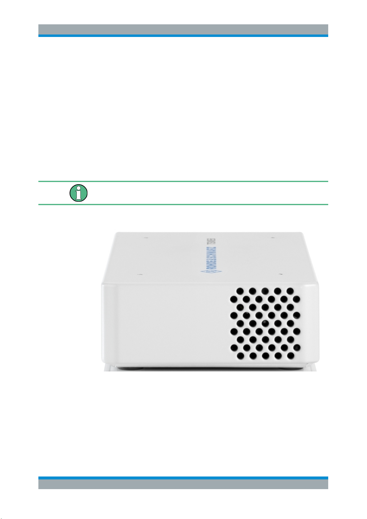
The front panel of the R&S TSME6 does not provide any connectors or control elements for operation.
Behind the right side of the rear panel (with the ventilation openings), 4 status LEDs
are located. These LEDs display the following states:
●
LEDs ON: R&S TSME6 ready for operation, RF-PLLs initialized correctly
●
LEDs OFF: R&S TSME6 is off or RF-PLLs initialized not correctly
If the fans are off (temperature on the controller board < 60° C), the LEDs are partially
covered by the fan blades.
Figure 3-1: R&S TSME6 - front panel
8User Manual 4900.0033.02 ─ 04
Page 9
R&S®TSME6
3.2 Rear Panel View
Instrument Tour
Rear Panel View
Instrument damage caused by cleaning agents
Cleaning agents contain substances such as solvents (thinners, acetone, etc.), acids,
bases, or other substances. Solvents can damage the front panel labeling, plastic
parts, or screens, for example.
Never use cleaning agents to clean the outside of the instrument. Use a soft, dry, lintfree dust cloth instead.
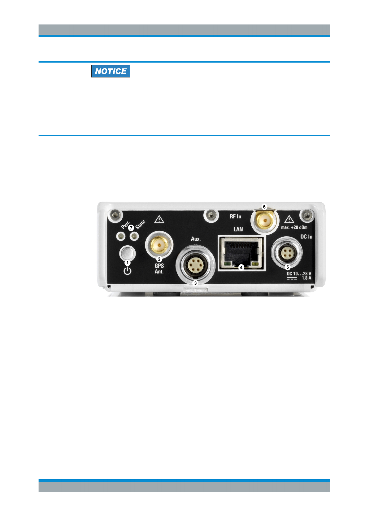
This figure shows the rear panel view of the R&S TSME6. The individual elements are
described in more detail in the subsequent sections.
Figure 3-2: R&S TSME6 - rear panel
1 = Power ON/OFF
2 = GPS antenna connector
3 = AUX connector
4 = LAN connector with LEDs
5 = DC IN connector
6 = RF IN connector (50 Ω)
7 = Pwr./State LEDs
Power ON/OFF
The On/Off key switches the device on and off if power is supplied via the DC IN connector. For details, see Chapter 5.3, "Switching the Instrument On and Off",
on page 35.
GPS antenna connector
An SMA connector is provided for the supplied external active GPS antenna (antenna
power: 3 V, max. 25 mA).
9User Manual 4900.0033.02 ─ 04
Page 10
R&S®TSME6
Instrument Tour
Rear Panel View
The integrated multi-GNSS (GPS / BeiDou / Galileo / GLONASS) receiver allows to
use three satellite systems in parallel. This offers an accuracy improvement of 30 % to
50 % by using a second constellation of satellites.
Following combinations are allowed:
●
GPS only
●
GPS / GLONASS / Galileo
●
GPS / BeiDou
The R&S TSME6 can perform untethered dead reckoning in tunnels to provide position
information even if no satellites are available. The untethered dead reckoning is performed in the device itself by built-in electronic gyroscopes.
For enabling untethered dead reckoning, see Chapter 5.1.8, "Enabling Untethered
Dead Reckoning ", on page 28.
Depending on the intended use, the respective valid regulations regarding lightning
protection of the antennas and regarding vehicle installation must be observed during
installation.
AUX connector
The AUX connector can be used to connect additional devices, such as a signal generator that provides an external reference frequency for the R&S TSME6, or a synchronization cable for multiple R&S TSME6 connected to one host PC.
LAN connector with LEDs
The LAN connector provides a high-speed Gigabit Ethernet interface with an RJ 45
connector using IPv4. It is required to connect the R&S TSME6 to a host PC.
The LEDs on the LAN connector indicate the status of the connection to the host PC.
LED 1 is on the left side of the connector, LED 2 is on the right.
Table 3-1: LAN LED 1 states and their meaning
LED state Description
green Connection established
green, blinking LAN sending or receiving, or identifying connected device
Table 3-2: LAN LED 2 states and their meaning
LED state Description
off No connection
yellow Physical connection established
yellow, blinking Identifying connected device
DC IN connector
The DC IN connector is required for the DC power supply (10-28 V, max. 1.8 A). For
details, see Chapter 5.1.4, "Connecting the DC Power Supply", on page 20.
10User Manual 4900.0033.02 ─ 04
Page 11
R&S®TSME6
Instrument Tour
Rear Panel View
RF IN connector (50 Ω)
The optional multi-band RF antenna (700 MHz to 2.6 GHz) or the device providing the
RF signal is connected to the instrument's RF INPUT via a cable equipped with an
appropriate connector (SMA female, 50 Ω input impedance, VSWR type 2.0).
Risk of instrument damage
Do not overload the maximum allowed input of 20 dBm. Non-compliance will destroy
the input mixer.
Depending on the intended use, the respective valid regulations regarding lightning
protection of the antennas and regarding vehicle installation must be observed during
installation.
Pwr./State LEDs
Table 3-3: POWER and STATE LED states and their meaning
STATE LED POWER LED Meaning
off off no power supply connected at DC IN
power supply off
power supply < 10 V
off yellow standby
off green, blinking (2 Hz) FGPA configuration in progress
red
(up to 5 seconds
during startup)
off green R&S TSME6 ready, not connected
green green connected
green, blinking rapidly
green, blinking 2 Hz green Instrument is identified by the software
red, blinking 2 Hz green temperature warning (controller board temperature =
red (continuous) green temperature error (controller board temperature above
green FPGA configuration finished, preparing for start
green measuring
75° C ... 80° C)
80° C)
*The fans are temperature-controlled and below a temperature of 60° C on the controller board, the fans are in status OFF.
11User Manual 4900.0033.02 ─ 04
Page 12
R&S®TSME6
4.1 Technology Options
Option Concept
Technology Options
4 Option Concept
The R&S TSME6 scanner consists of the R&S TSME6 hardware as well as a set of
(specified) technology and band options when it comes from the factory.
Technology options allow the R&S TSME6 to scan the input based on a specific technology, for example, LTE. All technology options can be installed on the same instrument; the R&S TSME6 can measure various technologies simultaneously.
Following technology options are available (for current availabilities see http://
www.rohde-schwarz.com/product/TSMx.html):
Table 4-1: Available R&S TSME6 technology options
Options Order number Description
R&S TSME6-K10 4900.2459.02 R&S TSME6 scanner option: Block IQ
R&S TSME6-K21 4900.2188.02 R&S TSME6 scanner option: WCDMA
R&S TSME6-K22 4900.2165.02 R&S TSME6 scanner option: CDMA2000
R&S TSME6-K23 4900.2194.02 R&S TSME6 scanner option: GSM
R&S TSME6-K24 4900.1242.02 R&S TSME6 scanner option: 1xEV-DO Rev. A
R&S TSME6-K25 4900.2242.02 R&S TSME6 scanner option: CW
R&S TSME6-K26 4900.2142.02 R&S TSME6 scanner option: TETRA
R&S TSME6-K27 4900.2120.02 R&S TSME6 scanner option: RF-Power Scan
R&S TSME6-K28 4900.2136.02 R&S TSME6 scanner option: WiMAX™
R&S TSME6-K29 4900.2171.02 R&S TSME6 scanner option: LTE
R&S TSME6-K30 4900.2113.02 R&S TSME6 scanner option: LTE MIMO 2x2,4x2,4x4
R&S TSME6-K32 4900.2288.02 R&S TSME6 scanner option: LTE eMBMS
R&S TSME6-K34 4900.2207.02 R&S TSME6 scanner option: NB-IoT/Cat NB1-Scan-
ning
R&S TSME6-K35 4900.2465.02 R&S TSME6 scanner option: LTE M
R&S TSME6-K40 4900.2259.02 R&S TSME6 Automatic Channel Detection (ViCom
only, not for R&S ROMES)
R&S TSME6-K50 4900.2436.02 R&S TSME6 scanner option: 5G NR scanning
R&S TSME6-K80 4900.2442.02 pR&S TSME6 scanner option: BTS PE Enabler
12User Manual 4900.0033.02 ─ 04
Page 13
R&S®TSME6
4.2 Band Options
Option Concept
Option Sharing Concept
The R&S TSME6 hardware simultaneously measures in all wireless communications
bands from 350 MHz to 6 GHz. Using band licenses, more cost-efficient configurations
are available for applications where only a limited number of bands need to be measured simultaneously.
These configurations limit the number of bands that can be measured in parallel. You
can reconfigure the bands for each measurement as desired. Upgrade options are
available to increase the bandwidth of the R&S TSME6 from a limited number of bands
to full bandwidth. Following band options are available:
Table 4-2: Available R&S TSME6 band options
Options Order number Description
R&S TSME6-KAB 4900.2107.02 All bands measured simultaneously
R&S TSME6-K1B 4900.2094.02 1 band measured simultaneously
R&S TSME6-K2B 4900.2088.02 2 bands measured simultaneously
R&S TSME6-K3B 4900.2071.02 3 bands measured simultaneously
R&S TSME6-K4B 4900.2065.02 4 bands measured simultaneously
R&S TSME6-K5B 4900.2059.02 5 bands measured simultaneously
R&S TSME6-KUB 4900.2307.02 Upgrade: 1 additional band measured simultaneously
The R&S TSME6 band assignment can be reconfigured by the user (see Chap-
ter 6.1.4, "Configuring Measurement Bands - "Band Configuration"", on page 46).
For an overview of available cellular bands and their characteristics see Chapter A,
"Available Cellular Bands", on page 62.
4.3 Option Sharing Concept
Definition TSME Group
A group of TSMEs are all TSME or TSME6 receivers, which are loaded by a TSME
Admin (independent of their synchronization).
Technology Options
As soon as a technology option is valid on at least one TSME or TSME6 of the group,
it is allowed to perform measurements on all connected receivers for this technology in
the allowed frequency bands of the respective receiver.
13User Manual 4900.0033.02 ─ 04
Page 14

R&S®TSME6
Option Concept
Option Sharing Concept
Allowed Frequency Bands
An "All Band Option" (KAB) allows to measure the complete frequency band supported
by the hardware. On a TSME6, the complete frequency band is slightly larger than on
a TSME.
If there is no "All Band Option" (KAB) in a receiver, but only a non-empty set of band
options for 1 to 5 bands (K1B, ... K5B) each, then the upper limited number of bands
can be selected from a table for this receiver, which are then allowed for all measurements.
The number of bands to be measured simultaneously is the sum of all activation numbers x from valid KxB options with a maximum of 5.
Example:
If two K1B and one K2B are installed on a TSME6, then it is permitted to measure in 4
bands simultaneously for this TSME6.
Special Scenario: MIMO
If a K300 is installed on a TSME or TSME6, then a measurement for technology option
index 130 (LTE MIMO) can be made on this TSME or TSME6 on all frequencies supported by the hardware.
The 5G NR FR2 demodulation with several TSME6 is also supported.
14User Manual 4900.0033.02 ─ 04
Page 15
R&S®TSME6
5.1 Putting into Operation
Preparing for Use
Putting into Operation
5 Preparing for Use
● Putting into Operation............................................................................................. 15
● Connecting Multiple R&S TSME6s to One Host PC............................................... 29
● Switching the Instrument On and Off...................................................................... 35
● Connecting the R&S TSME6 to a Software Application for the First Time..............35
This section describes the basic steps to be taken when setting up the R&S TSME6 for
the first time.
Risk of injury due to disregarding safety information
Observe the information on appropriate operating conditions provided in the data sheet
to prevent personal injury or damage to the instrument. Read and observe the basic
safety instructions provided with the instrument, in addition to the safety instructions in
the following sections. In particular:
●
Do not use an isolating transformer to connect the instrument to the AC power supply.
●
Do not open the instrument casing.
Risk of instrument damage due to inappropriate operating conditions
Specific operating conditions are required to ensure accurate measurements and to
avoid damage to the instrument. Observe the information on appropriate operating
conditions provided in the basic safety instructions and the instrument's data sheet.
Instrument damage caused by electrostatic discharge
Electrostatic discharge (ESD) can damage the electronic components of the instrument
and the device under test (DUT). Electrostatic discharge is most likely to occur when
you connect or disconnect a DUT or test fixture to the instrument's test ports. To prevent electrostatic discharge, use a wrist strap and cord and connect yourself to the
ground, or use a conductive floor mat and heel strap combination.
15User Manual 4900.0033.02 ─ 04
Page 16
R&S®TSME6
Preparing for Use
Putting into Operation
Risk of instrument damage during operation
An unsuitable operating site or test setup can cause damage to the instrument and to
connected devices. Ensure the following operating conditions before you switch on the
instrument:
●
The instrument is dry and shows no sign of condensation.
●
The instrument is positioned as described in the following sections.
●
Signal levels at the input connectors are all within the specified ranges.
EMI Suppression
Electromagnetic interference (EMI) may affect the measurement results.
To suppress generated electromagnetic interference (EMI):
●
Use only double shielded cables for RF and GPS connection when not using the
standard accessory.
●
Always terminate open cable ends.
●
DC-based lab networks are not allowed to be used for power supply.
●
LAN cable length to the next PC or switch must be < 30m.
●
Note the EMC classification in the data sheet.
● Unpacking and Checking the Instrument................................................................ 16
● Accessory List.........................................................................................................17
● Cascading R&S TSME6s........................................................................................17
● Connecting the DC Power Supply...........................................................................20
● Setting Up the LAN Connection to the Host PC......................................................22
● Connecting External Devices..................................................................................27
● Connecting a Kensington Lock............................................................................... 28
● Enabling Untethered Dead Reckoning ...................................................................28
5.1.1 Unpacking and Checking the Instrument
Check the equipment for completeness using the delivery note and the accessory lists
for the various items. Check the instrument for any damage. If there is damage, immediately contact the carrier who delivered the instrument. Make sure not to discard the
box and packing material.
Packing material
Retain the original packing material. If the instrument needs to be transported or shipped later, you can use the material to protect the control elements and connectors.
16User Manual 4900.0033.02 ─ 04
Page 17
R&S®TSME6
5.1.2 Accessory List
5.1.3 Cascading R&S TSME6s
Preparing for Use
Putting into Operation
The instrument comes with the following accessories:
●
Printed Getting Started manual
●
LAN cable
●
GPS antenna
●
12 V DC power supply cable (cigarette lighter cable)
●
4 connecting screws
Rackmounting
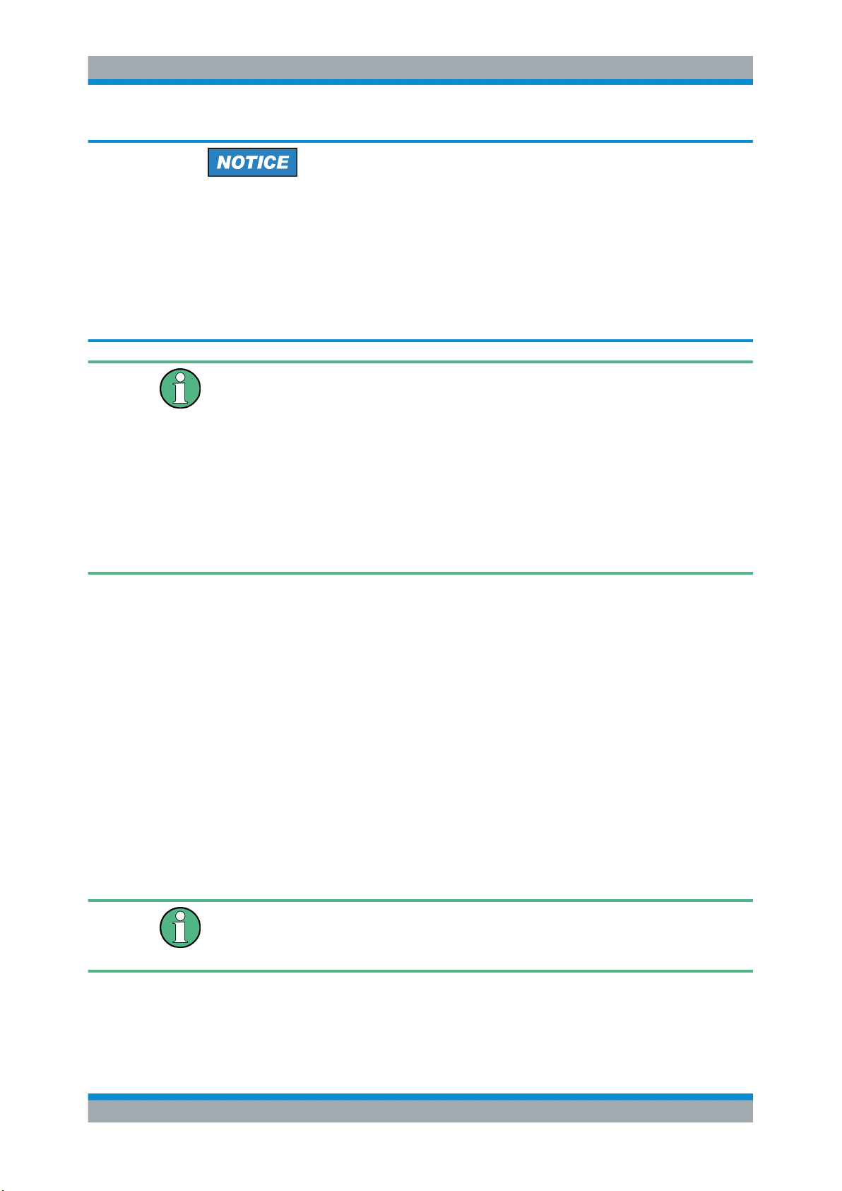
The R&S TSME6 can be installed in a 19 inch rack using a rack adapter kit for one to
four R&S TSME6s (option R&S TSME6-Z2, R&S no. 4900.1030.02). The installation
instructions are part of the adapter kit.
Figure 5-1: Rackmounting of 2 R&S TSME6s
Figure 5-2: Rackmounting of 2 R&S TSME6s (reverse orientation of R&S TSME6s)
17User Manual 4900.0033.02 ─ 04
Page 18
R&S®TSME6
Preparing for Use
Putting into Operation
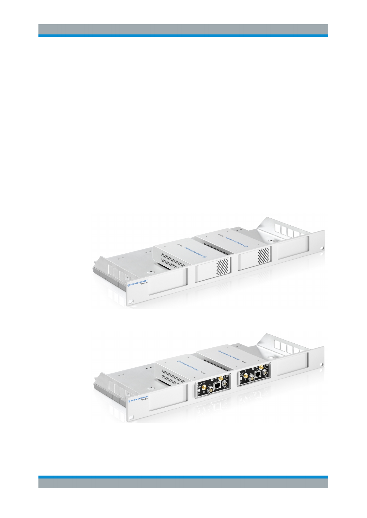
Figure 5-3: Rackmounting of 4 R&S TSME6s
Figure 5-4: Rackmounting of 4 R&S TSME6s (reverse orientation of R&S TSME6s)
Risk of instrument damage due to overheating
An insufficient airflow can cause the instrument to overheat, which may disturb the
operation and even cause damage. Make sure that all fan openings are unobstructed
and that the airflow perforations are unimpeded, particularly when the instrument is
installed in a rack or packed in a backpack. The R&S TSME6 draws in fresh air from
the front pane and warm air flows out at its panes. Thus, if no active cooling is installed, ensure that the following surrounding spaces to the instrument are kept clear:
●
Front pane: minimum 2 cm
●
Left/right panes: minimum 1 cm
Other mounting options
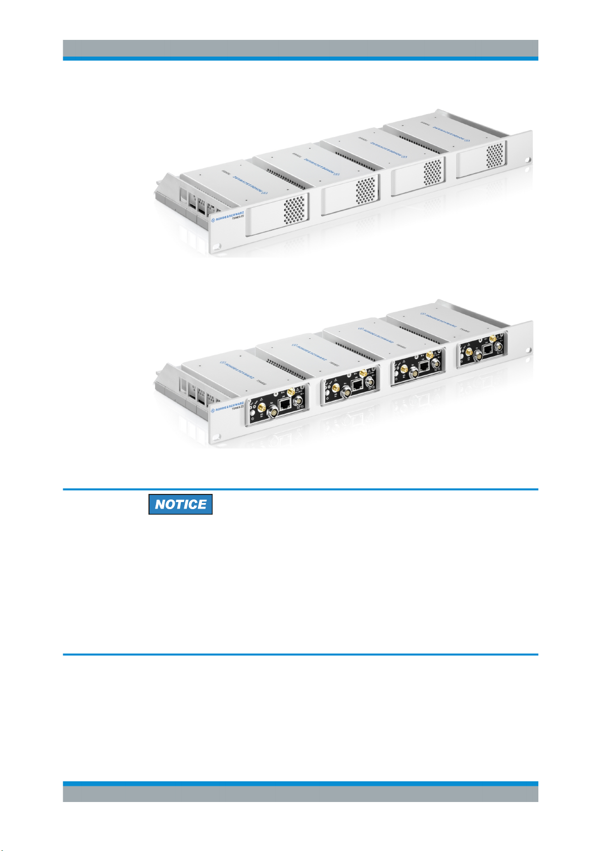
To connect two R&S TSME6 devices directly, perform the following steps.
1. Screw the connecting elements (R&S No. 4900.0804.00) on the top of the R&S
TSME6.
18User Manual 4900.0033.02 ─ 04
Page 19
R&S®TSME6
Preparing for Use
Putting into Operation
● Torque: 0.66 Nm ± 0.05 Nm
● Secure with liquid plastic
Figure 5-5: Connecting elements
1 = Connecting elements (R&S No.4900.0804.00)
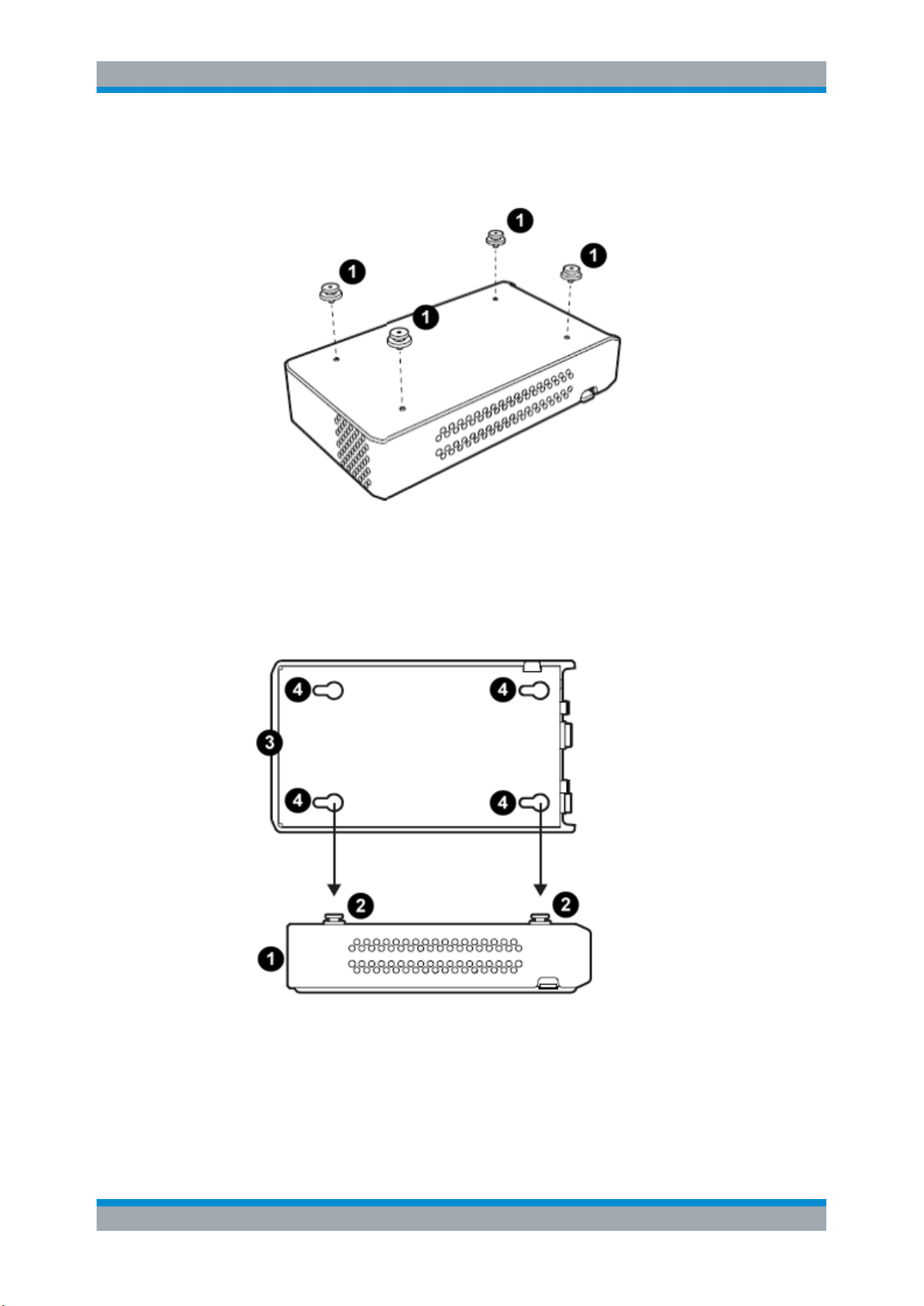
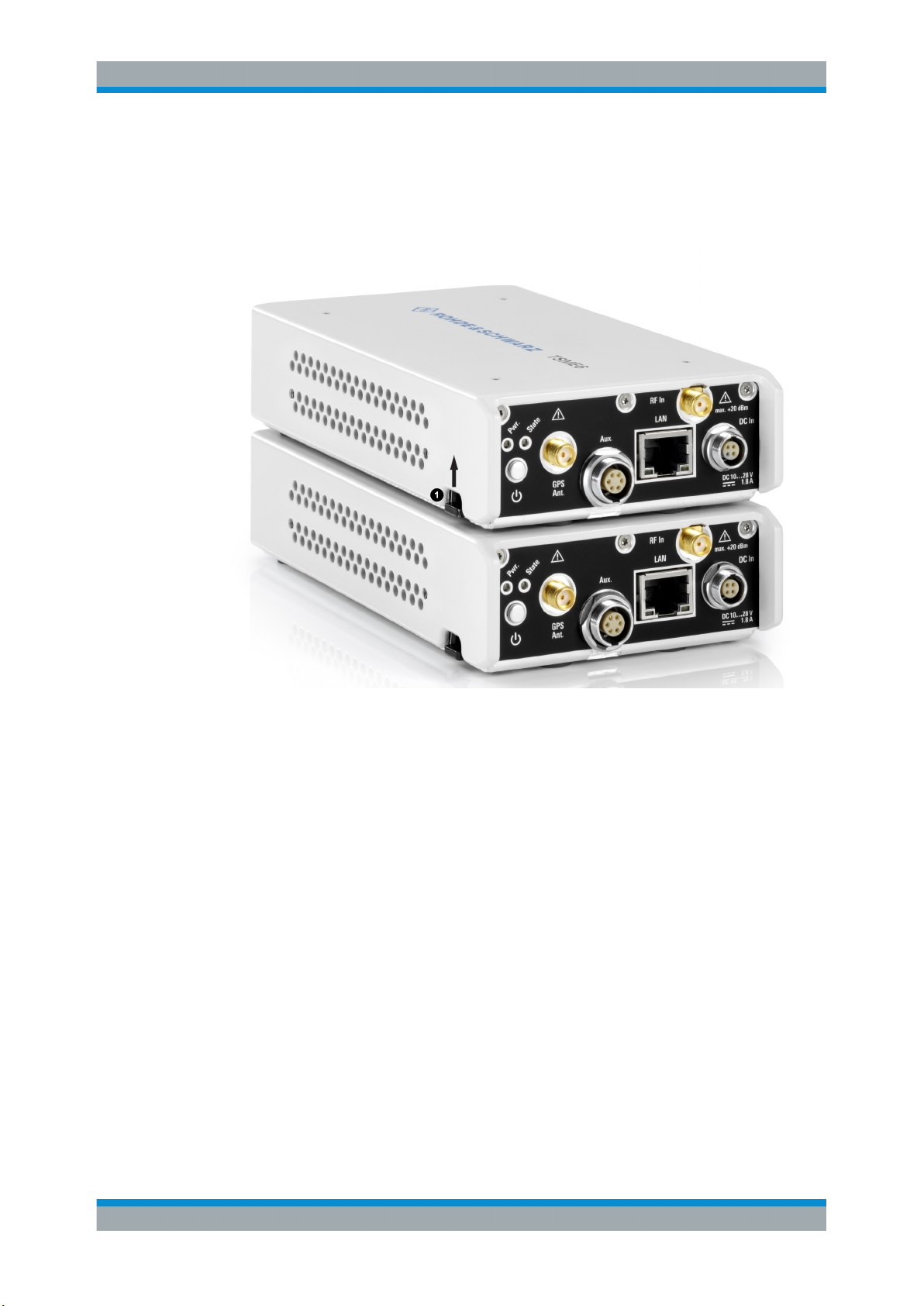
2. Align the connecting elements with the holes on the bottom of a second R&S
TSME6 and press the R&S TSME6 down.
Figure 5-6: Aligning R&S TSME6s
1 =
1st R&S TSME6
2 = Connecting screws
3 =
2nd R&S TSME6
4 = Holes on the bottom pane of R&S TSME6
19User Manual 4900.0033.02 ─ 04
Page 20
R&S®TSME6
Preparing for Use
Putting into Operation
3.
Push the 1st R&S TSME6 to the front until the mechanism locks.
To disconnect the R&S TSME6, lift the release button on the pane of the upper R&S
TSME6 and slide it until the device is released.
Figure 5-7: Disconnect two R&S TSME6s
1 = Release button
5.1.4 Connecting the DC Power Supply
The DC power supply connector is on the rear panel of the unit. Voltages from 10 V to
28 V are supported. There is no need to set the used voltage manually.
Possible power cable connections
The R&S TSME6 can work with the following DC power supplies:
●
Cigarette lighter power supply (for example in a vehicle) using the supplied DC
power cable
●
Optional AC power supply and power cable R&S TSME6-Z1 (see )
●
Proprietary power supply with an adapted power cable
Using the supplied cigarette lighter power supply cable
► To use the power supply from a cigarette lighter, connect the supplied power cable
from the R&S TSME6 to the cigarette lighter.
20User Manual 4900.0033.02 ─ 04
Page 21
R&S®TSME6
Preparing for Use
Putting into Operation
Connecting a proprietary power supply
► To use a proprietary DC supply with the R&S TSME6 power cable, demount the
cigarette lighter adapter from the supplied power cable and connect the open ends
of the cable to the proprietary power supply. Be sure to respect the correct polarity
(see Figure 5-8).
Figure 5-8: Supplied power cable with cigarette lighter adapter
Danger of shock!
To avoid a shock hazard and instrument damage, note the following:
●
After moisture condensation, allow the instrument to dry before switching on.
●
The instrument is still power-supplied while it is in standby mode, that is, with the
power button switched off, but still connected with the DC power supply.
●
After connecting the power supply, the instrument is immediately under power.
●
The supplied DC connector is intended for disconnection.
●
If any DC supply other than R&S TSME6-Z1 is used:
– The DC supply must be in accordance with IEC / EN / UL / CSA 60950-1 or
IEC / EN / UL / CSA EN EN61010-1.
– Use only Safety Extra Low Voltage (SELV) power supplies
– Observe the DC input range of 10 V to 27 V with maximum of 1.8 A (inrush cur-
rent)
– The 12 V vehicle cigarette lighter socket must be fused
21User Manual 4900.0033.02 ─ 04
Page 22

R&S®TSME6
5.1.5 Setting Up the LAN Connection to the Host PC
Preparing for Use
Putting into Operation
To control and run measurements with the R&S TSME6, a host PC or notebook with
LAN interface is required.
The R&S TSME6 is equipped with a network interface and can be connected to an
Ethernet LAN (local area network). The interface can be used to connect the R&S
TSME6 to a host PC.
The following scenarios are possible.
●
Connection between PC and R&S TSME6(s) using static IP addresses.
●
Connection between PC and R&S TSME6(s) using dynamical generated IP
addresses (Auto-IP).
Operating Modes
●
"Full auto-IP" operating mode
IP addresses are automatically generated on PC and R&S TSME6(s) if the following conditions are met:
– PC network interface is configured to obtain an IP address automatically
– IP address stored in R&S TSME6(s) is not in range 169.254.0.1 –
169.254.255.254 (inclusive).
Note: This is the IP address set by the R&S TSME Device Manager.
●
"Partial auto-IP" operating mode
IP address is automatically generated on PC and a static IP address is used on
R&S TSME6 if the following conditions are met:
– PC network interface is configured to obtain an IP address automatically
– IP address stored in R&S TSME6 is in range 169.254.0.1 – 169.254.255.254
(inclusive).
Note: This is the IP address set by the R&S TSME Device Manager.
●
"Static IP" operating mode
IP address is manually set on PC and a static IP used on R&S TSME6 if the following conditions are met:
– PC LAN interface is configured to use a user-defined IP address, not in range
169.254.0.1 – 169.254.255.254 (inclusive).
Recommendations/Limitations of Operating Modes
●
"Full auto-IP" operating mode
– Only 1 PC and 1 or more R&S TSME6 devices per LAN interface, either con-
nected directly or via a L2 switch. (This operating mode shall not be used when
more than 1 PC is physically connected to the same subnetwork, e.g. via the
switch.)
– PC’s LAN interface shall not receive an IP from a DHCP server. (The IP
address generated for PC shall be matching following pattern:
169.254.X.Y.)
– All R&S TSME6 devices on the same LAN interface shall be configured with
stored IP addresses not in the range 169.254.1.0 – 169.254.254.255 (inclusive)
to prevent conflicts.
22User Manual 4900.0033.02 ─ 04
Page 23

R&S®TSME6
Preparing for Use
Putting into Operation
Note: R&S TSME6 devices with stored IP addresses in ranges 169.254.0.1 –
169.254.0.255 (inclusive) or 169.254.255.0 – 169.254.255.254 (inclusive) are
effectively operating in "partial auto-IP" operating mode.
– Depending on software accessing the R&S TSME6 devices, it may be manda-
tory to configure the stored IP addresses in all R&S TSME6 devices to be
unique.
Example: R&S TSME Device Manager does not have this requirement, R&S
ROMES / R&S Nestor may have such requirements depending on the use
made internally of the stored IP address as unique identifier.
●
"Partial auto-IP" operating mode
This mode shall only be used for specific cases, "full auto-IP" or "static IP" operating modes shall be preferred.
– 1 or more PCs and 1 or more R&S TSME6 devices per LAN interface, either
connected directly or via a L2 switch
– Each of the PC’s LAN interface physically connected to the sub network shall
not receive an IP from a DHCP server. (The IP address generated for PC shall
be matching following pattern: 169.254.X.Y.)
– All R&S TSME6 devices on the same LAN interface shall be configured with
stored IP addresses in the ranges 169.254.0.1 – 169.254.0.255 (inclusive) or
169.254.255.0 – 169.254.255.254 (inclusive), and use unique IP addresses.
These ranges are important to prevent conflicts with IP addresses dynamically
generated for the PC LAN interfaces.
Note: If a R&S TSME6 is shared with 2 or more PCs, and its stored IP address
is not in the defined range above, this may lead in rare cases to IP conflicts. It
is therefore recommended to respect this rule.
●
"Static IP" operating mode
– 1 or more PCs and 1 or more R&S TSME6(s), either connected directly or via a
L2 switch.
– Other network devices are permitted, as long as all IP addresses used are
unique.
This section describes how to configure the LAN interface for a single R&S TSME6. It
includes the following topics:
● Configuring the LAN Interface on the Host PC....................................................... 23
● Firewall Configuration............................................................................................. 26
● Connecting the R&S TSME6 to the Host PC.......................................................... 27
5.1.5.1 Configuring the LAN Interface on the Host PC
Each R&S TSME6 has the default IP address 192.168.0.2. It is recommended that you
define the fixed IP address 192.168.0.1 to the host PC or configure the host PC to
obtain an IP address automatically ("Auto-IP").
To control the R&S TSME6 from the host PC, the LAN interface of the host PC must be
configured as follows:
1. Press the "Windows" key or the [CTRL + ESC] key combination on your keyboard
to access the Windows "Start" menu.
23User Manual 4900.0033.02 ─ 04
Page 24

R&S®TSME6
Preparing for Use
Putting into Operation
2. Type "Control Panel" and select this application.
3. Select "Control Panel > Network and Internet > Network and Sharing Center".
4. Select "Change adapter settings".
5. Double-click the LAN interface with which the R&S TSME6 is connected.
The items used by the LAN connection are displayed.
6. Select the entry named "Internet Protocol Version 4 (TCP/IPv4)".
7. Select the "Properties" button.
8. Configure the following TCP/IP settings:
a) Use any "Auto-IP" operating mode.
Select "Obtain an IP address automatically".
24User Manual 4900.0033.02 ─ 04
Page 25

R&S®TSME6
Preparing for Use
Putting into Operation
b) Use "Static IP" operating mode.
● Select "Use the following IP address" (fixed IP, no dynamic range)
● IP address: 192.168.0.1 (recommended)
● Subnet mask: 255.255.255.0
● No Default Gateway
9. Enable the use of 9-kB-jumbo frames:
a) Return to the "Local Area Connection Properties" dialog box.
b) Select the entry for the LAN adapter and then "Properties".
c) Switch to the "Advanced" tab.
25User Manual 4900.0033.02 ─ 04
Page 26

R&S®TSME6
5.1.5.2 Firewall Configuration
Preparing for Use
Putting into Operation
d) Select the "Jumbo Frames" property and the "Value":"9014 Bytes".
Note: this setting may cause problems in Windows, but it is an important
prerequisite for correct operation of the R&S TSME6.
See "Does the host provide a GBit LAN connector and support 9k jumbo
frames? " on page 57.
10. Close the Control Panel, reboot the host PC and check if the connection can be
established successfully (see Chapter 7.1, "Guide to Solve Instrument Connection
Problems", on page 55
If your firewall is active, make sure that it is configured as described in Chapter 5.1.5.2,
"Firewall Configuration", on page 26.
The firewall can be turned off on the LAN interface or on with all the mandatory configurations.
If your firewall is active, make sure that your program is allowed to communicate
through the firewall. Following ports should be available:
●
RxPort (TSME6->PC): Port 17476
●
TxPort (PC->TSME6): Port 5140 and 16962
Also, the following parameters must be configured to decide if a specific program is
allowed to pass the firewall.
●
Multicast IP address for TSME: 224.17.4.76
●
Multicast Address for TSME6: 239.192.1.7
●
IP-Address of TSME6 has to be allowed as well: 192.168.0.2 (example)
Note: In "full auto-IP" operating mode, the IP address generated for the R&S
TSME6 has to be allowed.
●
Allow UDP Protocol
●
Allow Multicast Protocol
●
Allow executed application (ROMES, NESTOR, TsmeDeviceManager for examples)
●
Allow Network-Interface TSME(s) are connected to
●
Allow Network-Profile active on Network-IF TSME is connected to
Even if all these parameters are set properly, this rule can be overwritten in Windows
Firewall by a blocking rule. Furthermore on first execution of a program, windows ask
the user to decide on which network profiles communication through the firewall shall
be allowed. If it is set correct by user, the firewall is in a good state.
26User Manual 4900.0033.02 ─ 04
Page 27

R&S®TSME6
5.1.5.3 Connecting the R&S TSME6 to the Host PC
Preparing for Use
Putting into Operation
The R&S TSME6 has a built-in 1000BASE-T (802.3ab), 1 Gbit/s Ethernet interface.
The host PC must have a separate 1 Gbit network interface card with an independent
LAN connection.
Dedicated LAN adapter and IP address for host PC
It is important for the host PC to have its own dedicated LAN adapter for the connection to one or more R&S TSME6s (or a switch), rather than being integrated in a regular office network.
If multiple R&S TSME6s are connected to one host PC, following rules are valid.
●
Using "static IP" or "partial auto-IP" operating mode, it is important to define unique
IP addresses for each instrument using the R&S TSME6 Device Manager (see
R&S TSME6 User Manual, chapter Configuring the R&S TSME6).
●
Using "full auto-IP" operating mode, it is recommended to define unique IP
addresses for each instrument, but depending on software run, it may not be mandatory.
► Connect the supplied LAN cable to the LAN connector on the rear panel of the
R&S TSME6, and to the host PC.
Windows 10 automatically detects the network connection and all devices in the
same subnet when the R&S TSME6 is switched on.
5.1.6 Connecting External Devices
The SMA connector is sensitive to mechanical stress. Use the following handling precautions.
●
Always use a torque wrench and mount the cable end with 60 Ncm.
●
Do not stack adapters directly at the SMA connector. If you need to use adapters
(e.g: SMA to N), then always use a specific adapter cable (R&S no. 4900.1700.00).
The following external devices are required for standard operation):
●
Connect the instrument to the power supply as described in Chapter 5.1.4, "Con-
necting the DC Power Supply", on page 20.
●
Connect the PC or notebook LAN port to the LAN port of the R&S TSME6 as
described in Chapter 5.1.5, "Setting Up the LAN Connection to the Host PC",
on page 22.
●
Connect the (optional) antenna's SMA-connector to the RF IN connector.
●
Connect the GPS antenna to the GPS ANT connector of the instrument for time
synchronization to a GPS signal (3 V, max. 25 mA for active antenna). To ensure
time synchronization of the R&S TSME6, it is required to have a GPS antenna connected. A missing GPS antenna will lead over time to the point that signals cannot
be detected anymore.
27User Manual 4900.0033.02 ─ 04
Page 28

R&S®TSME6
5.1.7 Connecting a Kensington Lock
Preparing for Use
Putting into Operation
●
Connect the R&S TSME30DC / R&S TSME44DC according to the measurement
setup description in R&S®TSME30DC / R&S® TSME44DC Ultracompact Down-
converters Getting Started.
Risk of instrument damage
Do not overload the input power at the RF input connector, otherwise the input stage
could be severely damaged. For maximum allowed values, see the data sheet.
The R&S TSME6 provides a connector for a Kensington lock, which can be used to
secure a mobile device against theft. The connector is on the side panel of the instrument.
Figure 5-9: Connector for a Kensington lock on theR&S TSME6
5.1.8 Enabling Untethered Dead Reckoning
The following steps are necessary to enable untethered dead reckoning with the integrated receiver (see "GPS antenna connector" on page 9) of the R&S TSME6.
1. Mount the R&S TSME6 device fixed to the frame of a car.
2. Power on the R&S TSME6 device.
3. Activate "Dead Reckoning" in the used software (for details, refer to R&S ROMES,
R&S NESTOR or R&S ViCom documentation).
4. Wait until the used software reports a "3D fix" (time may vary depending on the
configured GNSS).
28User Manual 4900.0033.02 ─ 04
Page 29

R&S®TSME6
5.2 Connecting Multiple R&S TSME6s to One Host PC
Preparing for Use
Connecting Multiple R&S TSME6s to One Host PC
5. To calibrate the instrument, the following driving procedures have to be performed
in a safe environment.
a) 720 degrees right turn.
b) 720 degrees left turn.
c) Drive a straight line with a velocity exceeding 40 km/h.
Note: Whenever the device is switched off, the calibration procedure must be
repeated for the next usage of dead reckoning.
After finishing the calibration, the used software should report a fix state "GPS+DR" or
"3D+DR", in case satellite reception is lost the fix state will change to "DR only".
If using "DR only", the accuracy of the reported position will decrease over time, if it
falls below a certain threshold the receiver will report the state "No Fix".
Due to the compatibility of R&S TSME and R&S TSME6, the combined usage of R&S
TSME and R&S TSME6 devices in a LTE-MIMO setup is possible.
Using multiple R&S TSME6 devices requires sufficient capacity of the used network
link.
A single R&S TSME6 can fully utilize a gigabit ethernet connection. If the network link
reaches its maximum capacity, the measurement system decreases the network
throughput to avoid network overload. The result is a reduced performance of the R&S
TSME6.
In a MIMO scenario or when using multiple R&S TSME6devices for load balancing
applications, a network link can be shared by several TSM6 devices. In these cases, it
is recommended to use several network ports on your PC. This applies also for the
measurement of multiple technologies on the used R&S TSME6 device.
5.2.1 Using Two R&S TSME6s in Parallel
Using two R&S TSME6s in parallel enhances the measurement capability compared to
a single R&S TSME6, and can increase measurement speed.
Synchronized devices are time-synchronous, not phase-synchronous.
It is recommended to connect every R&S TSME6s with a dedicated network connection to the used PC.
A R&S TSME6 intelligently captures signals of multiple technologies at the same time,
if they fall within its 20 MHz frontend.
29User Manual 4900.0033.02 ─ 04
Page 30

R&S®TSME6
Preparing for Use
Connecting Multiple R&S TSME6s to One Host PC
If two R&S TSME6s are connected, and a technology option is installed on at least one
of the R&S TSME6s, the measurement software can perform measurements on both
R&S TSME6 frontends. Thus you can create a virtual 40 MHz frontend.
Therefore, performing measurements on combined R&S TSME6s is faster than performing them on separate R&S TSME6s in shared spectrum networks.
Using two R&S TSME6s in parallel requires the following options:
●
A band option (R&S TSME6-KxB) on each R&S TSME6
●
Identical technology options on both R&S TSME6s to perform measurements on
both R&S TSME6 frontends simultaneously
The following table demonstrates some sample configurations and applications for parallel usage.
Table 5-1: Sample configurations and applications for parallel usage
Configuration R&S TSME6 1 R&S TSME6 2 Application
Config 1 Options GSM, KAB KAB Increase measurement speed
Measurements GSM GSM
Config 2 Options LTE, KAB WCDMA, GSM, KAB Use scanners separately; join
Measurements GSM, WCDMA, LTE GSM, WCDMA, LTE
Config 3 Options LTE, MIMO, KAB LTE, KAB Use scanners separately; join
Measurements LTE, MIMO LTE, MIMO
5.2.2 LTE MIMO Setups with Two R&S TSME6s
Basic LTE MIMO measurements are possible with a single R&S TSME6, which can
analyze two different transmission paths of a signal from two different transmit antennas. A single R&S TSME6 can determine the RSRP/Q and RS SINR results for both
paths (see documentation of the measurement software for details).
If two R&S TSME6s are connected to one host PC, multiple signals can be received by
two receive antennas and processed in one application. This is useful, for example, to
analyze a MIMO matrix, condition numbers, or ranks, or generally to optimize the LTE
MIMO setup.
Table 5-2: Required options for sample (minimum) configuration for LTE MIMO measurements with 2
R&S TSME6s
R&S TSME6 Option
1 KxB, LTE (K29), LTE MIMO (K30)
for increased speed
for LTE MIMO measurement
2 none (MIMO extension option R&S TSME6-K300 installed by default)
Required Connections
1. Connect the SYNC-cable (R&S TSME6-ZC2, R&S no. 4900.1800.02) to the Aux.
connectors of all R&S TSME6 devices in this setup.
30User Manual 4900.0033.02 ─ 04
Page 31

R&S®TSME6
Preparing for Use
Connecting Multiple R&S TSME6s to One Host PC
Figure 5-10: SYNC-cable connected to Aux. connectors of 2 R&S TSME6 devices
2. Connect the power cable (R&S TSME-ZYC, R&S no. 1514.7290.02) to the DC In
connectors of all R&S TSME6 devices in this setup.
Figure 5-11: Power cable connected to DC In connectors of 2 R&S
1 = Power cable (connecting 2 R&S TSME6 devices)
TSME6 devices
For setups with two R&S TSME6s, use the power supply R&S TSME-Z1, (R&S no.
1514.6913.02).
31User Manual 4900.0033.02 ─ 04
Page 32

R&S®TSME6
Preparing for Use
Connecting Multiple R&S TSME6s to One Host PC
3. Connect one LAN cable per LAN connector of all R&S TSME6 devices in this
setup.
Figure 5-12: LAN cable connected to LAN connectors of 2 R&S TSME6 devices
1 = LAN cable
5.2.3 LTE MIMO Setups with Four R&S TSME6s
If four R&S TSME6s are connected to one host PC, multiple signals can be received
by four receive antennas and processed in one application. This is useful, for example,
to perform LTE MIMO path measurements or throughput/CQI estimations (in addition
to the results using two R&S TSME6s).
Table 5-3: Required options for sample (minimum) configuration for LTE MIMO measurements with 4
R&S TSME6 Option
1 KxB, LTE (K29), LTE MIMO (K30)
2 none (MIMO extension option R&S TSME6-K300 installed by default)
3 none (MIMO extension option R&S TSME6-K300 installed by default)
4 none (MIMO extension option R&S TSME6-K300 installed by default)
Required Connections
R&S TSME6s
1. Connect the SYNC-cable to the Aux. connectors of all R&S TSME6 devices in this
setup.
32User Manual 4900.0033.02 ─ 04
Page 33

R&S®TSME6
Preparing for Use
Connecting Multiple R&S TSME6s to One Host PC
Figure 5-13: SYNC-cable connected to Aux. connectors of 4 R&S TSME6 devices
2. Connect the power cable (R&S TSME6-ZYC4, R&S no. 4900.1846.02) to the DC
In connectors of all R&S TSME6 devices in this setup.
Figure 5-14: Power cable connected to DC In connectors of 4 R&S
1 = Power cable (connecting 4 R&S TSME6 devices)
TSME6 devices
33User Manual 4900.0033.02 ─ 04
Page 34

R&S®TSME6
Preparing for Use
Connecting Multiple R&S TSME6s to One Host PC
For setups with four R&S TSME6s, use the following power supply (R&S TSMA6Z1, R&S no. 1523.8450.02) .
Figure 5-15: AC Power Supply (four R&S TSME6s)
3. Connect a LAN cable to the LAN connectors of all R&S TSME6 devices in this
setup.
Figure 5-16: LAN cable connected to LAN connectors of 4 R&S
1 = LAN cable
TSME6 devices
34User Manual 4900.0033.02 ─ 04
Page 35

R&S®TSME6
5.3 Switching the Instrument On and Off
Preparing for Use
Connecting the R&S TSME6 to a Software Application for the First Time
To switch on the instrument
1. Use the supplied power cable to connect the power supply to the instrument.
2. After the power cable is connected, the R&S TSME6 is powered on.
After booting, the instrument switches to the idle mode and is ready to be accessed by
an application.
Switching off the instrument
When you press the On/Off key on the rear panel of the R&S TSME6 to switch it off,
the instrument changes to standby mode. In standby mode, the program execution on
the instrument is stopped immediately, but the instrument is still under power connection.
Do not switch off during connection process
Do not switch off the instrument while a connection to the application software is being
established, otherwise the application might not be able to close properly.
As a result, the software could crash and must be shut down from the Windows Task
Manager.
Removing the power supply
If you remove the power supply and reconnect it later, the instrument automatically
boots when power returns.
5.4 Connecting the R&S TSME6 to a Software Application for the First Time
The following procedure describes the steps performed when you connect the R&S
TSME6 to a software application (R&S ROMES, R&S NESTOR, or R&S ViCom) for the
first time. Note that this process may take a few minutes initially.
1. Switch on the R&S TSME6 and the host PC.
2. Start the R&S ROMES / R&S NESTOR / R&S ViCom application on the host PC.
The application searches for R&S TSME6s connected to the host PC.
If the R&S TSME6 is detected by the software for the first time, the software downloads the calibration files from the R&S TSME6 to the host PC. This may take a
few minutes.
35User Manual 4900.0033.02 ─ 04
Page 36

R&S®TSME6
Preparing for Use
Connecting the R&S TSME6 to a Software Application for the First Time
3. If the firewall settings have not been defined to include the R&S TSME6 applica-
tions, a Windows Security Alert may appear. Change the firewall settings to permit
access to the R&S TSME6 applications:
a) In the Windows Control Panel, select "System and Security > Windows Firewall
> Allow apps to communicate through Windows Defender Firewall".
Figure 5-17: Firewall settings to permit application access
b) Allow the specified application module(s) to communicate on all network
types (domain, private, public).
In particular, select:
● "TSME Device Manager" Application
● "tsmeping"
c) Depending on which application is used, also select the following items:
● R&S ROMES:
ROMES.exe
–
Dll Loader for PHYLIS Modules
–
(in the ROMES application folder)
● R&S NESTOR:
RohdeSchwarz.Nestor.exe
–
–
● R&S ViCom:
Dll Loader for PHYLIS Modules (RuSProcessPhysicalLayer.exe)
4. The application checks which firmware versions are installed on the R&S TSME6
and which version was used to boot the R&S TSME6. Up to four firmware versions
can be stored on the R&S TSME6.
The following procedure depends on the detected version(s).
36User Manual 4900.0033.02 ─ 04
Page 37

R&S®TSME6
Preparing for Use
Connecting the R&S TSME6 to a Software Application for the First Time
● If the firmware version required by the application was used for booting, the
application establishes a connection to the R&S TSME6 directly.
● If the firmware version required by the application is available on the R&S
TSME6, but was not used for booting, the application reboots the R&S TSME6
using the required firmware version. Then the application establishes a connection to the R&S TSME6.
37User Manual 4900.0033.02 ─ 04
Page 38

R&S®TSME6
Preparing for Use
Connecting the R&S TSME6 to a Software Application for the First Time
● If the firmware version required by the application is not yet available on the
R&S TSME6, the application uploads the required firmware version to the R&S
TSME6 (this may take about one minute). The application reboots the R&S
TSME6 using the required firmware version, then establishes a connection to
the R&S TSME6.
● If the firmware version required by the application is not yet available on the
R&S TSME6, and all three storage spaces for firmware are occupied by other
versions, the application must do the following:
a) Clear all storage space for firmware versions on the R&S TSME6 (this may
take about one minute).
b) Upload the required firmware version to the R&S TSME6 (this may take about
one minute).
c) Reboot the R&S TSME6 using the required firmware version.
d) Establish a connection to the R&S TSME6.
38User Manual 4900.0033.02 ─ 04
Page 39

R&S®TSME6
6.1 Using the R&S TSME Device Manager
Configuring the R&S TSME6
Using the R&S TSME Device Manager
6 Configuring the R&S TSME6
Measurements are performed on the R&S TSME6 via the R&S ROMES, R&S NESTOR or R&S ViCom interface. Depending on the installed software options, the network is either scanned for individual standards, or globally over all frequency bands.
Details on scanning networks are described in the R&S ROMES, R&S NESTOR and
R&S ViCom manuals.
Basic device configuration tasks can be performed directly on the R&S TSME6, via the
host PC, using the "R&S TSME Device Manager".
The "R&S TSME Device Manager" is a configuration software tool for scanners of the
R&S TSME and R&S TSMA family. This utility is part of the R&S®TSME installation
package. It can also be installed together with R&S ROMES, R&S NESTOR and
R&S ViCom, and is available for download from the Rohde & Schwarz product website
http://www.rohde-schwarz.com/product/TSMx.html.
To start the R&S TSME Device Manager
► To start the R&S TSME Device Manager, double-click the desktop icon or select
the "R&S®TsmeTools" program entry in the Windows "Start" menu.
When you start the R&S TSME Device Manager, a dialog box with different tabs is
displayed (see Figure 6-1).
●
Selecting the device
The R&S TSME Device Manager can configure any connected R&S TSME6 that
the software detects in the LAN. The individual devices are identified uniquely by
their serial number. By selecting one of the "Available Devices" by its serial number
in the R&S TSME Device Manager dialog box, you determine which R&S TSME6
the current configuration applies to.
●
Updating the device selection list
If additional R&S TSME6s become available after the R&S TSME Device Manager
has started, you must select the "Refresh Device List" button so the new devices
are included in the "Available Devices" list.
●
Updating the displayed device data
If the current configuration or device information has changed and is not yet displayed correctly in the R&S TSME Device Manager, select the "Refresh Device
Data" button to update the display.
If a connection to a R&S TSME6 is not possible (for example due to mismatch of subnetmask configuration), only limited information is displayed. For example, no information about installed options is available in this case.
39User Manual 4900.0033.02 ─ 04
Page 40

R&S®TSME6
6.1.1 Obtaining Device Information - "Device Info"
Configuring the R&S TSME6
Using the R&S TSME Device Manager
● Obtaining Device Information - "Device Info".......................................................... 40
● Changing IP Addresses - "Network Configuration"................................................. 43
● Installing and Managing Software License Keys - "Options".................................. 44
● Configuring Measurement Bands - "Band Configuration"....................................... 46
● Obtaining Firmware and Correction Data Updates - "Updates".............................. 48
● Aligning R&S TSME6 Manually - "Self Alignment"..................................................49
● Configuring Downconverter R&S TSME30DC/TSME44DC - "Downconverter Con-
figuration"................................................................................................................ 50
The most important configuration settings for each available R&S TSME6 are displayed in the "Device Info" tab of the "R&S TSME Device Manager".
40User Manual 4900.0033.02 ─ 04
Page 41

R&S®TSME6
Configuring the R&S TSME6
Using the R&S TSME Device Manager
Figure 6-1: Tab "Device Info"
This includes the following information:
If an R&S TSME30DC downconverter is correctly connected, a second table with the
relevant data for the downconverter is displayed.
41User Manual 4900.0033.02 ─ 04
Page 42

R&S®TSME6
Configuring the R&S TSME6
Using the R&S TSME Device Manager
Table 6-1: R&S TSME6 device information
Label Description
Device
The device can be a receiver R&S TSME6 or a downconverter R&S TSME30DC.
For the R&S TSM30DC, only a reduced set of data is displayed.
Device Type Type of device (TSME family, TSMA family)
Material Number Order number of the R&S TSME6
Variant Number Precise device type (variant)
Serial Number Unique ID of the R&S TSME6
Product Change Index Version of the device
MAC Address Network address of the R&S TSME6
FPGA
Available FPGA Bit File Versions
Current FPGA Bit File Version Currently used firmware version
Power Board
Serial Number Unique ID of the power board
Product Change Index Version of the power board
Controller Board
Serial Number Unique ID of the controller board
Product Change Index Version of the controller board
Temperature Current temperature of the hardware in [°]C
RF Board
Serial Number Unique ID of the RF board
Product Change Index Version of the RF board
Temperature Current temperature of the hardware in [°]C
Correction Data
Version Current version of the calibration data saved on the device
Previous firmware version backups stored on the device (see also Chap-
ter 6.1.5, "Obtaining Firmware and Correction Data Updates - "Updates"",
on page 48 )
●
Type
Date Timestamp of creating and saving the calibration data on the device
TCXO Date Date of correction data for the internal reference
Factory
The original factory calibration data are saved on the device.
●
Update
An improved set of calibration data is available and saved on the
device. (See Figure 6-5.)
42User Manual 4900.0033.02 ─ 04
Page 43

R&S®TSME6
6.1.2 Changing IP Addresses - "Network Configuration"
Configuring the R&S TSME6
Using the R&S TSME Device Manager
Device Analysis Output
Furthermore, any warnings, errors or information concerning the device status that
may be available are displayed in the "Device Analysis Output" table. This table is
available on all tabs, at the bottom of the R&S TSME Device Manager window.
Depending on their relevance, the messages are assigned to the following categories:
●
info: information for the user, no action required
●
warning: warning on behalf of the instrument - should be solved
●
error: error on behalf of the instrument - must be solved before further operation
In case measurement problems occur with the R&S TSME6, check the "Device Analysis Output" table for any errors that may have been detected. If available, a repair function is provided.
By default, each R&S TSME6 is delivered with the pre-configured IP address
192.168.0.2. However, if multiple R&S TSME6s are connected to the same host PC,
each device must have a unique IP address.
You can change the IP address for the connected R&S TSME6s directly via the R&S
TSME Device Manager.
If necessary, the LAN adapter settings on the host PC must also be adapted accordingly to reconnect with the R&S TSME6 (see also Chapter 5.1.5, "Setting Up the LAN
Connection to the Host PC", on page 22). In particular, the host PC (LAN adapters)
must use the subnet in which the IP addresses of the R&S TSME6s are located.
Define the IP address in the "Network Configuration" tab of the R&S TSME Device
Manager. The currently active IP address for the selected R&S TSME6 is displayed for
reference. It remains active until you select the "Accept Network Changes" button.
Auto IP Address
If "full auto-IP" operating mode is used, the "R&S TSME Device Manager" shows an
extra field indicating the automatically generated IP address used for the connection to
the host (see Figure 6-2 with example IP address: 169.254.233.79).
In this case, the IP address stored in R&S TSME6 (here 192.168.0.2) is still used as an
identifier for the connection by the software applications, i.e. a kind of virtual IP
address.
If partial auto-IP operating mode or static IP operating mode is used, the "R&S TSME
Device Manager" does not show this extra field and the IP address stored in the R&S
TSME6 is also the IP address used for the physical connection (in this example:
192.168.0.2)
43User Manual 4900.0033.02 ─ 04
Page 44

R&S®TSME6
6.1.3 Installing and Managing Software License Keys - "Options"
Configuring the R&S TSME6
Using the R&S TSME Device Manager
Figure 6-2: Tab "Network Configuration"
Applying changes to the LAN configuration
Changes to the IP Address configuration in the R&S TSME Device Manager are only
applied when you select the "Accept Network Changes" button. The reconfigured R&S
TSME6 is then accessible only via the new IP address.
All new devices are preconfigured and specified technology and band options are
already installed. Only if you obtain additional software options later, you have to
enable the options with the corresponding software license keys.
License keys are shipped as a printed "License Keys List". Advance deliveries may
consist of a PDF file. Unregistered software licenses can be downloaded from the
Rohde & Schwarz website (https://extranet.rohde-schwarz.com/service). For details
see the "Installation Instructions for Options".
(Note: previously, license keys were shipped as xml files.)
Prerequisites to install software license keys
To install a software license key, the following conditions must apply:
●
PC/notebook is connected via Gbit LAN adapter, with "Jumbo Frames" (9 kB)
enabled
●
The (registered) software license key must be available
Software license keys are installed using the "R&S TSME Device Manager" ("Options"
tab).
44User Manual 4900.0033.02 ─ 04
Page 45

R&S®TSME6
Configuring the R&S TSME6
Using the R&S TSME Device Manager
Figure 6-3: Tab "Options"
For each option, the following information is displayed:
Information for options that are no longer valid because their expiry date has passed
are listed as "Inactive Options".
To replace temporary by permanent software license keys, contact your Rohde &
Schwarz sales representative.
Table 6-2: Software license key information
Label Description
Option Type Band or technology option name
Option Material No. Order number of the option
Option key Software license key number
Privilege Usage type (customer, services, demo)
Time Stamp Time the software license key was installed
License Count Number of times the (band upgrade) option is installed
45User Manual 4900.0033.02 ─ 04
Page 46

R&S®TSME6
Configuring the R&S TSME6
Using the R&S TSME Device Manager
Label Description
Activation Type Activation can be permanent or temporary
Valid From Start of validity for temporary license
Valid To End of validity for temporary license
Time to Expiration Time left until license expires
Option Index for internal use only
Format ID for internal use only
Finding the software license key files
Previously, license keys were shipped as xml files. This function is only available for
compatibility reasons.
If you do not know the precise path and file name of the required software license key,
you can browse through the host PC's file system directly from the "R&S TSME Device
Manager", by selecting the "Browse" button in the "Options" tab.
Entering key codes
Enter the 30-digit key code from the "License Keys List" in the "Key" field.
Alternatively, if available, copy the key code from the supplied PDF license key file and
paste it in the "Key" field.
To install the software license key on the currently selected R&S TSME6, select the
"Install" button (see Figure 6-3).
Installing a software license key
The software license key for which you have entered the key code in the R&S TSME
Device Manager is installed on the currently selected R&S TSME6 when you select the
"Install" button. It then appears in the "Active Options" list with its validity dates and
other information (see Figure 6-3).
6.1.4 Configuring Measurement Bands - "Band Configuration"
Depending on which options are installed, various different bands and technologies
can be scanned by the R&S TSME6.
Before you can configure the measurement bands you must install all required software license keys, see Chapter 6.1.3, "Installing and Managing Software License Keys
- "Options"", on page 44.
The band configuration is stored permanently on the R&S TSME6.
When using a R&S TSME6 with a limited number of measurement bands, you must
consider the band configuration of the scanner when planning a measurement task.
The scanner provides only measurement results for those bands that are currently configured on the scanner.
46User Manual 4900.0033.02 ─ 04
Page 47

R&S®TSME6
Configuring the R&S TSME6
Using the R&S TSME Device Manager
Example:
A R&S TSME6 is configured with band option TSME-K2B (2 bands measured simultaneously). During the last measurement, the R&S TSME6 was used to perform measurements in 900 MHz and 1800 MHz bands. For the next measurement, the R&S
TSME6 can still only be used in 900 MHz and 1800 MHz bands, unless you change
the band configuration using the "R&S TSME Device Manager".
The band configuration is defined in the "Band Configuration" tab of the "R&S TSME
Device Manager".
Select the bands that are to be scanned by the R&S TSME6 in the "Band Table".
Which bands are available is independent of the installed technology options; all installed technologies can be scanned in all configured bands at the same time.
The number of bands available for selection depends on the installed band options.
Figure 6-4: Tab "Band Configuration"
The current band configuration for the selected R&S TSME6 is displayed for reference.
It remains active until you select the "Accept Band Changes" button.
47User Manual 4900.0033.02 ─ 04
Page 48

R&S®TSME6
Configuring the R&S TSME6
Using the R&S TSME Device Manager
Band configuration changes
Changes to the band configuration cannot be made randomly; within any 48-hour
period, the band configuration may only be changed up to 5 times (where one "configuration change" may consist of several band changes at the same time, see "Applying
band configuration changes" on page 48).
A counter is decremented after each (applied) change. How many changes have
already been performed and how many are still possible within the current time frame
is displayed at the bottom of the "Band Configuration" tab of the "R&S TSME Device
Manager".
Red dates indicate the changes recently made, while green dates indicate possible
changes left.
Applying band configuration changes
Changes to the band configuration are only applied to the R&S TSME6 when you
select the "Accept Band Changes" button in the "Band Configuration" tab of the "R&S
TSME Device Manager".
Only then the counter for possible band changes (within 48 hours) is decremented.
6.1.5 Obtaining Firmware and Correction Data Updates - "Updates"
The "R&S TSME Device Manager" is always provided with the most recent basic
FPGA (section 0). If a newer one becomes available due to security or functional
issues, a message is indicated in the "Device Analysis Output" at the bottom of the
"R&S TSME Device Manager" window. In this case, and only in this case, it is recommended that you install this update on your R&S TSME6.
The correction data on your R&S TSME6 should always be kept up-to-date. Available
updates are also indicated in the "Device Analysis Output" and it is recommended that
you install them.
If a R&S TSME30DC downconverter is correctly connected, the basic FPGA and correction data for the downconverter are also displayed in a second line.
Risk of inoperability of device due to FPGA update
Before performing an update, make sure you have a stable power supply and the LAN
connection will not be interrupted. Both updates take a few minutes.
If the LAN connection is interrupted during an FPGA update, the device may become
inoperable. Thus, only install such an update if it is explicitly recommended by a message in the "Device Analysis Output" of the "R&S TSME Device Manager" or by the
Rohde & Schwarz support center.
You can update the basic FPGA or the correction data on your R&S TSME6 directly
from the "R&S TSME Device Manager", in the "Update" tab. The currently installed ver-
48User Manual 4900.0033.02 ─ 04
Page 49

R&S®TSME6
Configuring the R&S TSME6
Using the R&S TSME Device Manager
sions and the newest supported version (of the FPGA) or the minimum recommended
version (of the correction data) are indicated.
Figure 6-5: Tab "Updates"
To perform an update
1. In the "R&S TSME Device Manager", select the serial number of the R&S TSME6
to be updated.
2. In the "Updates" tab, select the "Update" button for either the "Basic FPGA" or the
"Correction Data".
When updating the correction data, you are asked to select a directory to store a
backup of your current correction data.
6.1.6 Aligning R&S TSME6 Manually - "Self Alignment"
During self-alignment, the R&S TSME6 determines alignment values for the I/Q filter,
ADC offset and the I/Q imbalance.
49User Manual 4900.0033.02 ─ 04
Page 50

R&S®TSME6
Configuring the R&S TSME6
Using the R&S TSME Device Manager
Figure 6-6: Tab "Self Alignment"
Start Self Alignment
To start the self-alignment manually, select the "Start Self Alignment" button in the "Self
Alignment" tab of the "R&S TSME Device Manager".
6.1.7 Configuring Downconverter R&S TSME30DC/TSME44DC - "Downconverter Configuration"
In this tab, you can configure the IF output receiver and the RF input antenna of the
R&S TSME30DC/TSME44DC downconverter. For details, refer to the R&S
TSME30DC / R&S TSME44DC Getting Started.
50User Manual 4900.0033.02 ─ 04
Page 51

R&S®TSME6
Configuring the R&S TSME6
Using the R&S TSME Device Manager
Figure 6-7: Tab "Downconverter Configuration"
IF Output Receiver Configuration
Specify the configuration of the IF output connectors of the R&S TSME30DC/
TSME44DC.
RF Input Antenna Configuration
●
Specify the configuration of the RF input antenna connectors of the R&S
TSME30DC.
– Bypass Antenna (< 6 GHz)
– mmWave Antenna 1 (24 GHz to 27.5 GHz)
– mmWave Antenna 2 (27 GHz to 30 GHz)
For R&S ViCom and R&S ROMES, the API allows only the configuration of frequencies of activated antenna ports.
NOTE: For the overlapping frequency range 27 GHz to 27.5 GHz, the "mmWAve
Antenna 1" is used by default.
●
Specify the configuration of the RF input antenna connectors of the R&S
TSME44DC.
– Bypass Antenna (< 6 GHz)
– mmWave Antenna 1 (24 GHz to 44 GHz)
For R&S ViCom and R&S ROMES, the API allows only the configuration of frequencies of activated antenna ports.
Accept Configuration
To confirm the current configuration settings, select the "Accept Configuration" button.
51User Manual 4900.0033.02 ─ 04
Page 52

R&S®TSME6
6.2 Interacting with R&S ROMES, R&S NESTOR, and R&S
6.2.1 Interacting with R&S ROMES
Configuring the R&S TSME6
Interacting with R&S ROMES, R&S NESTOR, and R&S ViCom
ViCom
Measurements are performed on the R&S TSME6 via the R&S ROMES, R&S NESTOR, or R&S ViCom interface. Depending on the installed technology options, the network is either scanned for individual standards, or globally over all frequency bands.
The following sections briefly describe the basic requirements for interaction between
the R&S TSME6 and the R&S ROMES, R&S NESTOR, or R&S ViCom interface. For
details on using these interfaces see the R&S ROMES, R&S NESTOR, and
R&S ViCom manuals.
Prerequisites
To perform measurements with the R&S ROMES application, the following prerequisites apply:
For details on R&S ROMES, see the manual provided on the software DVD.
●
R&S ROMES Installation (refer to R&S ROMES manual)
●
R&S ROMES option on dongle inserted (refer to R&S ROMES manual)
●
Required technology options installed on the R&S TSME6 (see Chapter 6.1.3,
"Installing and Managing Software License Keys - "Options"", on page 44).
●
Software options installed on the host PC (see information on the ROMES product
page on the Rohde & Schwarz website: https://www.rohde-schwarz.com/product/
ROMES > "Options")
After the R&S TSME6 has finished booting, start the R&S ROMES software application.
Automatic firmware updates
Each time R&S ROMES is started, the software automatically compares the firmware
version of the connected R&S TSME6 with the version currently available on the host
PC. If a newer version is available, it is copied to and installed on the R&S TSME6.
Up to three previously installed firmware versions are stored as backups and maintained on the R&S TSME6 (see also Chapter 6.1.1, "Obtaining Device Information -
"Device Info"", on page 40). Thus, it is not necessary to perform firmware updates on
the R&S TSME6 manually.
52User Manual 4900.0033.02 ─ 04
Page 53

R&S®TSME6
6.2.2 Interacting with R&S NESTOR
Configuring the R&S TSME6
Interacting with R&S ROMES, R&S NESTOR, and R&S ViCom
Prerequisites
To perform measurements with the R&S NESTOR application, the following prerequisites apply:
For details on R&S NESTOR, see the manual provided on the software DVD.
●
R&S NESTOR installation on the host PC (refer to the R&S NESTOR manual)
●
R&S NESTOR option on dongle inserted in host PC (refer to the R&S NESTOR
manual)
●
LAN connection between the R&S TSME6 and the host PC (note the special LAN
adapter requirements specified in Chapter 5.1.5.1, "Configuring the LAN Interface
on the Host PC", on page 23)
●
Required technology options installed on the R&S TSME6 (see Chapter 6.1.3,
"Installing and Managing Software License Keys - "Options"", on page 44)
●
Software options installed on the host PC (see information on the NESTOR product
page on the Rohde & Schwarz website: https://www.rohde-schwarz.com/product/
NESTOR > "Options")
In particular, NESTOR SCN 1521.5031.xx (R&S Scanner Driver) is always required
to operate the R&S TSME6.
After the R&S TSME6 has finished booting, start the R&S NESTOR software application.
Automatic firmware updates
Each time R&S NESTOR is started, the software automatically compares the firmware
version of the connected R&S TSME6 with the version currently available on the host
PC. If a newer version is available, it is copied to and installed on the R&S TSME6.
Up to three previously installed firmware versions are stored as backups and maintained on the R&S TSME6 (see also Chapter 6.1.1, "Obtaining Device Information -
"Device Info"", on page 40). Thus, it is not necessary to perform firmware updates on
the R&S TSME6 manually.
6.2.3 Interacting with R&S ViCom
R&S ViCom interface is a software package to develop software applications, which
integrate the R&S TSME6 as an OEM product into customer software.
The R&S ViCom package is not part of the shipment.
53User Manual 4900.0033.02 ─ 04
Page 54

R&S®TSME6
Configuring the R&S TSME6
Interacting with R&S ROMES, R&S NESTOR, and R&S ViCom
Figure 6-8: R&S ViCom Architecture
The R&S ViCom package must be installed on the host PC. It includes documentation
and sample applications.
Scanner Options
In order to interact with the R&S TSME6 via the R&S ViCom interface, the corresponding scanner options must be installed on the device.
Open the R&S TSME6 Device Manager to see which scanner options are installed on
the device (see Chapter 6.1.3, "Installing and Managing Software License Keys -
"Options"", on page 44).
For details and information on how to configure the R&S ViCom interface and carry out
measurements with the R&S TSME6, refer to the R&S ViCom manual.
54User Manual 4900.0033.02 ─ 04
Page 55

R&S®TSME6
7.1 Guide to Solve Instrument Connection Problems
Troubleshooting
Guide to Solve Instrument Connection Problems
7 Troubleshooting
If errors occur during operation or connection of the R&S TSME6, the following information may help you solve the issue.
Most errors that may occur during measurements with the R&S TSME6 are indicated
in the host PC software (e.g. R&S ROMES, R&S NESTOR, or the R&S ViCom application) and must be solved within the software. This chapter refers only to errors that
occur directly on the R&S TSME6.
In case measurement problems occur with the R&S TSME6, check the "Device Analysis Output" table in the R&S TSME6 Device Manager for any errors that may have
been detected at a first measure (see "Device Analysis Output" on page 43). If available, a repair function is provided.
The following flow-diagram demonstrates how to check the LAN connection to the
instrument when initial connection fails:
55User Manual 4900.0033.02 ─ 04
Page 56

R&S®TSME6
Troubleshooting
Guide to Solve Instrument Connection Problems
Figure 7-1: Troubleshooting LAN Connection
56User Manual 4900.0033.02 ─ 04
Page 57

R&S®TSME6
Troubleshooting
Guide to Solve Instrument Connection Problems
Remarks to the troubleshooting flow-diagram
* For "full auto-IP" and "partial auto-IP" operating mode, following hints are valid:
●
R&S TSME6 IP addresses are unique and physically in the network range
(169.254.0.0 netmask 255.255.0.0).
●
In "full auto-IP" operating mode, user has no control on IP addresses physically
used.
** If the application using R&S TSME6 is not running as administrator, following problems may occur:
●
The static ARP table conflicts with the dynamic configuration of R&S TSME6.
Clean up the ARP table or run the application as administrator to verify if the configuration is working.
●
The host (respectively R&S TSME6) is not be able to send and receive a multicast
frame to IP address 239.192.1.5 port16962.
The following information may provide further solutions to frequent connection problems.
Does the host provide a GBit LAN connector and support 9k jumbo frames?
In some cases the Windows network adapter properties show that 9k are enabled, but
in fact the adapter does not support the setting. You can check this using this command:
netsh interface ipv4 show interfaces
The "MTU" value in each line indicates the maximum transmission unit. Make sure the
LAN adapter connected to the R&S TSME6 supports an MTU larger than 9000.
If the 9k jumbo frames cannot be enabled in the Windows dialog box, try the following
command:
netsh interface ipv4 set subinterface [Idx] mtu=9000
store=persistent
where [Idx] is the network Id of the LAN adapter
For more information on the required settings see step 9.
Are you using a USB2LAN adapter?
Consider using an R&S TSPC-U2L adapter, order no. 3593.8430.02.
57User Manual 4900.0033.02 ─ 04
Page 58

R&S®TSME6
Troubleshooting
Solving Other Miscellaneous Problems
Is the R&S TSME6 connected to the host PC properly?
Currently the R&S TSME6 does not answer to ICMP echo requests (PING). However,
for ViCom users, a R&S TSME6 Ping tool is available after installation of R&S ViCom
(C:\RuS\ViCom_19.3\tools\TSME\TsmePing.exe).
Is the PC configured to use the subnet 192.168.0.0 with a different IP address to
the R&S TSME6 (default: 192.168.0.2)?
(See also Chapter 5.1.5.1, "Configuring the LAN Interface on the Host PC",
on page 23.)
Are other applications trying to access the R&S TSME6 at the same time (e.g.
R&S ROMES, R&S NESTOR, R&S ViCom, R&S TSME6 Device Manager)?
Check the Windows TaskManager and look for associated processes. If necessary,
stop the processes.
Is the host using other network connections at the same time, such as VPN?
R&S TSME6 does not work when the PC is connected to VPN.
Is the connecting cable between the host and the R&S TSME6 the one provided
with the R&S TSME6?
Make sure you are using a quality CAT5e or better Gigabit Ethernet conform cable.
RJ45 connectors must be shielded, not plastic.
After switching the R&S TSME6 off and back on, is the power LED on the R&S
TSME6 blinking while the state LED is off?
This indicates that the TSME cannot boot. Contact Rohde & Schwarz Support Center.
7.2 Solving Other Miscellaneous Problems
In case measurement problems occur with the R&S TSME6, check the "Device Analysis Output" table in the "R&S TSME Device Manager" for any errors that may have
been detected as a first measure (see Chapter 6.1.1, "Obtaining Device Information -
"Device Info"", on page 40).
Problem: R&S ROMES does not detect the R&S TSME6............................................ 59
Problem: The R&S TSME Device Manager does not detect the R&S TSME6............. 59
Problem: The options in the R&S TSME Device Manager are lost...............................59
Problem: Error message: "No calibration data".............................................................59
Problem: R&S TSME6 does not provide measurement data........................................59
Problem: Instrument shuts down at lower temperature than expected......................... 59
Problem: Ethernet negotiation between PC and TSME/TSME6 is not successful with
an Intel network chip..................................................................................................... 59
58User Manual 4900.0033.02 ─ 04
Page 59

R&S®TSME6
Troubleshooting
Solving Other Miscellaneous Problems
Problem: R&S ROMES does not detect the R&S TSME6
Possible solutions:
●
Restart R&S ROMES, while the R&S TSME6 is connected and switched on.
●
Restart the PC and then start R&S ROMES, while the R&S TSME6 is connected
and switched on.
●
In case of no success, try to connect with "R&S TSME Device Manager" to see
details.
If you switch the instruments off and on again, be sure to switch on the R&S TSME6
before you start R&S ROMES!
Problem: The R&S TSME Device Manager does not detect the R&S TSME6
Solution:
Be sure you have administrator rights on the host PC running the "R&S TSME Device
Manager".
Problem: The options in the R&S TSME Device Manager are lost
Solution:
Contact the Rohde & Schwarz Support Center.
Problem: Error message: "No calibration data"
Solution:
Delete the TSME6_ID_4900.0004K02-XXXXXX.cal file in the application directory
(e.g.
C:\Program Files (x86)\Rohde-Schwarz\ROMES4.78 or C:\RuS\
ViCom_19.3\bin) where XXXXXX is the serial number of the R&S TSME6.
Problem: R&S TSME6 does not provide measurement data
Solution:
Delete the TSME6_ID_4900.0004K02-XXXXXX.cal file in the application directory
(e.g. C:\Program Files (x86)\Rohde-Schwarz\ROMES4.78 or
C:\RuS\ViCom_19.3\bin) where XXXXXX is the serial number of the R&S TSME6.
Problem: Instrument shuts down at lower temperature than expected
By default, the instrument is set to shut down when it reaches a temperature of 85° C
to prevent damage.
In rare occasions, it may shut down at a lower temperature. Check the "Device Analysis Output" in the "R&S TSME Device Manager" for a message and a repair function, if
available.
Problem: Ethernet negotiation between PC and TSME/TSME6 is not successful
with an Intel network chip
If PC and R&S TSME6 / R&S TSME are both powered on and physically connected
with a LAN cable, and the LAN LED 2 of the device (see Table 3-2) does not reach its
yellow state after a few seconds, and/or no connection is visible on PC side, this may
be due to following setting enabled in Intel’s Ethernet driver:
"Ultra Low Power Mode"
59User Manual 4900.0033.02 ─ 04
Page 60

R&S®TSME6
Troubleshooting
Contacting Customer Support
Disabling this setting should resolve the issue.
7.3 Contacting Customer Support
Technical support – where and when you need it
For quick, expert help with any Rohde & Schwarz product, contact our customer support center. A team of highly qualified engineers provides support and works with you
to find a solution to your query on any aspect of the operation, programming or applications of Rohde & Schwarz products.
Contact information
Contact our customer support center at www.rohde-schwarz.com/support, or follow this
QR code:
60User Manual 4900.0033.02 ─ 04
Page 61

R&S®TSME6
Troubleshooting
Contacting Customer Support
Figure 7-2: QR code to the Rohde & Schwarz support page
61User Manual 4900.0033.02 ─ 04
Page 62

R&S®TSME6
Available Cellular Bands
Annex
A Available Cellular Bands
The following cellular bands are available for selection for R&S TSME6s with a limited
band option (see Chapter 4, "Option Concept", on page 12).
Table A-1: Available cellular bands for the R&S TSME6
ID TSME Band Span Start [MHz] Stop [MHz]
1 "TETRA" span 1 375 435
span 2 445 475
span 3 865 881
span 4 910 926
2 "CDMA 400" span 1 410 493
3 "480" span 1 478 486
span 2 488 496
4 "700" span 1 698 862
5 "810" span 1 806 821
span 2 851 866
6 "850" span 1 806 940
7 "900" span 1 917 960
span 2 872 915
8 "1400" span 1 1427 1496
9 "PDC Japan" span 1 1447 1463
span 2 1495 1511
10 "1500/1600" span 1 1626 1661
span 2 1525 1559
11 "AWS" span 1 1710 1780
span 2 2110 2200
12 "1700" span 1 1749 1785
span 2 1840 1880
span 3 1695 1710
span 4 1995 2020
13 "1800" span 1 1710 1785
span 2 1805 1880
14 "1900" span 1 1850 1915
62User Manual 4900.0033.02 ─ 04
Page 63

R&S®TSME6
Available Cellular Bands
ID TSME Band Span Start [MHz] Stop [MHz]
span 2 1930 1995
15 "2100" span 1 1920 2010
span 2 2110 2200
16 "S-Band" span 1 2000 2020
span 2 2180 2200
17 "2600" span 1 2496 2690
18 "3500" span 1 3410 3490
span 2 3510 3590
19 "WiMAX 7.x" span 1 730 770
span 2 890 903
span 3 915 950
20 "WiMAX 8.A/TDD 1900/2000" span 1 1785 1805
span 2 1880 1930
span 3 2010 2025
21 "TDD 1800" span 1 1800 1830
22 "TDD 1930" span 1 1930 1990
23 "TDD 2300" span 1 2300 2400
24 "TDD 3300" span 1 3300 3400
25 "TDD 3400" span 1 3400 3600
26 "TDD 3600" span 1 3600 3800
27 "5000" span 1 5150 5925
28 "ISM-Band" span 1 433 435
span 2 2400 2500
29 "600" span 1 617 698
Table A-2: Additional information on cellular bands
ID Band Name Included standardized bands UL low UL high DL low DL high Duplex
1 "TETRA" T-GSM 380 380.2 389.8 390.2 399.8 FDD
T-GSM 410 410.2 419.8 420.2 429.8 FDD
GSM 450 450.4 457.6 460.4 467.6 FDD
TETRA 380 to 400 380 390 390 400 FDD
TETRA 410 to 430 410 420 420 430 FDD
TETRA 450 to 470 450 460 460 470 FDD
TETRA 900 870 876 915 921 FDD
63User Manual 4900.0033.02 ─ 04
Page 64

R&S®TSME6
ID Band Name Included standardized bands UL low UL high DL low DL high Duplex
Available Cellular Bands
2 "CDMA 400" CDMA2000/EV-DO Band Class 11
3 "480" GSM 480 478.8 486 488.8 496 FDD
4 "700" WiMAX 7.A 698 862 698 862 TDD
LTE Band 31 452.5 457.5 462.5 467.5 FDD
410 483 420 493 FDD
(400 MHz European PAMR Band)
CDMA2000/EV-DO Band Class 5
(450 MHz Band)
CDMA2000/EV-DO Band Class 19
(Lower 700 MHz Band)
LTE Band 12 (lower 700 A/B/C) 699 716 729 746 FDD
3GPP WCDMA XII 699 716 729 746 FDD
LTE Band 17 (lower 700 B) 704 716 734 746 FDD
GSM 710 698 716 728 746 FDD
LTE Band 44 TDD 703 803 703 803 TDD
CDMA2000/EV-DO Band Class 7
(Upper 700 MHz Band)
Band 13 (upper 700 C) 777 787 746 756 FDD
WiMAX 7.B 776 787 746 757 FDD
410 483 420 493 FDD
698 716 728 746 FDD
776 788 746 758 FDD
5 "810" T-GSM 810 806 821 851 866 FDD
6 "850" GSM 850 824 849 869 894 FDD
3GPP WCDMA XIII 777 787 746 756 FDD
CDMA2000/EV-DO Band Class 18
(700 MHz Public Safety Band)
LTE Band 14 (upper 700 D) 788 798 758 768 FDD
3GPP WCDMA XIV 788 798 758 768 FDD
WiMAX 7.C 788 798 758 768 FDD
WiMAX 7.D 788 798 758 768 FDD
GSM 750 777 793 747 763 FDD
LTE Band 28 (700 APT) 703 748 758 803 FDD
LTE Band 20 832 862 791 821 FDD
3GPP WCDMA XX 832 862 791 821 FDD
LTE Band 29 N/A N/A 717 728 FDD
LTE Band 68 698 728 753 783 FDD
LTE Band 67 N/A N/A 738 758 FDD
3GPP WCDMA V 824 849 869 894 FDD
787 799 757 769 FDD
LTE Band 5 824 849 869 894 FDD
64User Manual 4900.0033.02 ─ 04
Page 65

R&S®TSME6
ID Band Name Included standardized bands UL low UL high DL low DL high Duplex
Available Cellular Bands
7 "900" P-GSM 900 890 915 935 960 FDD
LTE Band 26 814 849 859 894 FDD
LTE Band 18 815 830 860 875 FDD
CDMA2000/EV-DO Band Class 0
(800 MHz Band)
CDMA2000/EV-DO Band Class 10
(Secondary 800 MHz Band)
CDMA2000/EV-DO Band Class 12
(800 MHz PAMR Band)
3GPP WCDMA VI 830 840 875 885 FDD
3GPP WCDMA XIX 830 845 875 890 FDD
3GPP WCDMA XXVI 814 849 859 894 FDD
LTE Band 27 807 824 852 869 FDD
LTE Band 6 830 840 875 885 FDD
LTE Band 19 830 845 875 890 FDD
TETRA 900 870 876 915 921 FDD
CDMA2000/EV-DO Band Class 3
(JTACS Band)
815 849 860 894 FDD
806 901 851 940 FDD
870 876 915 921 FDD
887 925 832 870 FDD
8 "1400" 3GPP WCDMA XI 1427.9 1447.9 1475.9 1495.9 FDD
9 "PDC Japan" 3GPP WCDMA XXI 1447.9 1462.9 1495.9 1510.9 FDD
10 "1500/1600" CDMA2000/EV-DO Band Class 20 (L-
E-GSM 900 (includes P-GSM 900) 880 915 925 960 FDD
R-GSM 900 (includes E-GSM 900) 876 915 921 960 FDD
3GPP WCDMA VIII 880 915 925 960 FDD
LTE Band 8 880 915 925 960 FDD
WiMAX 7.G 880 915 925 960 FDD
CDMA2000/EV-DO Band Class 9
(900 MHz Band)
CDMA2000/EV-DO Band Class 2
(TACS Band)
LTE Band 11 1427.9 1447.9 1475.9 1495.9 FDD
LTE Band 32 N/A N/A 1452 1496 FDD
LTE Band 45 1447 1467 1447 1467 TDD
3GPP WCDMA Band XXXII N/A N/A 1452 1496 FDD
LTE Band 21 1447.9 1462.9 1495.9 1510.9 FDD
Band)
880 915 925 960 FDD
872 915 917 960 FDD
1626 1660 1525 1559 FDD
65User Manual 4900.0033.02 ─ 04
Page 66

R&S®TSME6
ID Band Name Included standardized bands UL low UL high DL low DL high Duplex
Available Cellular Bands
11 "AWS" 3GPP WCDMA IV 1710 1755 2110 2155 FDD
12 "1700" 3GPP WCDMA IX 1749.9 1784.9 1844.9 1879.9 FDD
13 "1800" DCS 1800 1710 1785 1805 1880 FDD
LTE Band 24 1626.5 1660.5 1525 1559 FDD
3GPP WCDMA X 1710 1770 2110 2170 FDD
LTE Band 4 1710 1755 2110 2155 FDD
LTE Band 10 1710 1770 2110 2170 FDD
CDMA2000/EV-DO Band Class 15
(AWS Band)
WiMAX 6.A 1710 1770 2110 2170 FDD
LTE Band 66 1710 1780 2110 2200 FDD
LTE Band 9 (UMTS1700) 1749.9 1784.9 1844.9 1879.9 FDD
CDMA2000/EV-DO Band Class 4
(Korean PCS Band)
LTE Band 70 1695 1710 1995 2020 FDD
3GPP WCDMA III 1710 1785 1805 1880 FDD
LTE Band 3 1710 1785 1805 1880 FDD
1710 1755 2110 2155 FDD
1750 1780 1840 1870 FDD
14 "1900" PCS 1900 1850 1910 1930 1990 FDD
15 "2100" 3GPP WCDMA I 1920 1980 2110 2170 FDD
CDMA2000/EV-DO Band Class 8
(1800 MHz Band)
WiMAX 6.C 1710 1785 1805 1880 FDD
3GPP WCDMA II 1850 1910 1930 1990 FDD
3GPP WCDMA XXV 1850 1915 1930 1995 FDD
3GPP TDD incl. TD-SCDMA b 1850 1910 1930 1990 TDD
LTE Band 2 1850 1910 1930 1990 FDD
LTE Band 35 TDD 1850 1910 1850 1910 TDD
CDMA2000/EV-DO Band Class 1
(1900 MHz Band)
CDMA2000/EV-DO Band Class 14
(US PCS 1.9GHz Band)
LTE Band 25 (PCS A-G superset of
band 2)
LTE Band 1 1920 1980 2110 2170 FDD
CDMA2000/EV-DO Band Class 6
(2 GHz IMT2000 Band)
1710 1785 1805 1880 FDD
1850 1910 1930 1990 FDD
1850 1915 1930 1995 FDD
1850 1915 1930 1995 FDD
1920 1980 2110 2170 FDD
66User Manual 4900.0033.02 ─ 04
Page 67

R&S®TSME6
ID Band Name Included standardized bands UL low UL high DL low DL high Duplex
Available Cellular Bands
16 "S-Band" LTE Band 23 2000 2020 2180 2200 FDD
17 "2600" LTE Band 7 2500 2570 2620 2690 FDD
WiMAX 6.B 1920 1980 2110 2170 FDD
LTE Band 65 1920 2010 2110 2200 FDD
CDMA2000/EV-DO Band Class 21 (SBand)
CDMA2000/EV-DO Band Class 13
(25 GHz IMT-2000 Extension Band)
3GPP WCDMA VII 2500 2570 2620 2690 FDD
CDMA2000/EV-DO Band Class 16
(US 2.5 GHz Band)
CDMA2000/EV-DO Band Class 17
(US 2.5 GHz Forward Link Only Band)
LTE Band 41 TDD 2496 2690 2496 2690 TDD
WiMAX 3.A 2496 2690 2496 2690 TDD
WiMAX 3.B 2496 2572 2614 2690 FDD
LTE Band 38 TDD 2570 2620 2570 2620 TDD
3GPP TDD incl. TD-SCDMA d 2570 2620 2570 2620 TDD
2000 2020 2180 2200 FDD
2500 2570 2620 2690 FDD
2502 2568 2624 2690 FDD
2624 2690 FDD (DL
only)
18 "3500" 3GPP WCDMA XXII 3410 3490 3510 3590 FDD
19 "WiMAX 7.x" 7.x* lower 730 770 730 770 TDD
20 "WiMAX
8.A/TDD
1900/2000"
LTE Band 69 N/A N/A 2570 2620 FDD
LTE Band 22 3410 3490 3510 3590 FDD
7.x* mid 890 903 890 903 TDD
7.x* higher 915 950 915 950 TDD
WiMAX 8.A lower 1785 1805 1785 1805 TDD
WiMAX 8.A mid 1880 1930 1880 1930 TDD
WiMAX 8.A upper 2010 2025 2010 2025 TDD
3GPP TDD incl. TD-SCDMA a (lower) 1900 1920 1900 1920 TDD
LTE Band 33 TDD 1900 1920 1900 1920 TDD
3GPP TDD incl. TD-SCDMA c 1910 1930 1910 1930 TDD
LTE Band 37 TDD 1910 1930 1910 1930 TDD
3GPP TDD incl. TD-SCDMA f 1880 1920 1880 1920 TDD
LTE Band 39 TDD 1880 1920 1880 1920 TDD
3GPP TDD incl. TD-SCDMA a (upper) 2010 2025 2010 2025 TDD
67User Manual 4900.0033.02 ─ 04
Page 68

R&S®TSME6
ID Band Name Included standardized bands UL low UL high DL low DL high Duplex
Available Cellular Bands
21 "TDD 1800" WiMAX 8.G 1800 1830 1800 1830 TDD
22 "TDD 1930" LTE Band 36 TDD 1930 1990 1930 1990 TDD
23 "TDD 2300" LTE Band 40 TDD 2300 2400 2300 2400 TDD
24 "TDD 3300" WiMAX 4.A 3300 3400 3300 3400 TDD
25 "TDD 3400" LTE Band 42 TDD 3400 3600 3400 3600 TDD
LTE Band 34 TDD 2010 2025 2010 2025 TDD
3GPP TDD incl. TD-SCDMA e 2300 2400 2300 2400 TDD
WiMAX 1.A 2300 2400 2300 2400 TDD
WiMAX 1.B 2300 2400 2300 2400 TDD
WiMAX 2.D (lower) 2305 2320 2305 2320 TDD
WiMAX 2.D (upper) 2345 2360 2345 2360 TDD
WiMAX 2.E 2345 2360 2305 2320 FDD
WiMAX 2.F 2345 2360 2305 2320 FDD
LTE Band 30 2305 2315 2350 2360 FDD
WiMAX 4.B 3300 3400 3300 3400 TDD
WiMAX 4.C 3300 3400 3300 3400 TDD
26 "TDD 3600" LTE Band 43 TDD 3600 3800 3600 3800 TDD
27 "5000" LTE Band 46 TDD 5150 5925 5150 5925 TDD
28 "ISM-Band" ISM 433 433 435 433 435 TDD
29 "600" LTE Band 71 - US Digital Dividend 663 698 617 652 TDD
WiMAX 5L.A 3400 3600 3400 3600 TDD
WiMAX 5L.B 3400 3600 3400 3600 TDD
WiMAX 5L.C 3400 3600 3400 3600 TDD
WiMAX 5L.D 3400 3500 3500 3600 FDD
WiMAX 5H.A 3600 3800 3600 3800 TDD
WiMAX 5H.B 3600 3800 3600 3800 TDD
WiMAX 5H.C 3600 3800 3600 3800 TDD
LTE Band 47 TDD 5855 5925 5855 5925 TDD
ISM 5000 5725 5875 5725 5875 TDD
ISM 2400 2400 2500 2400 2500 TDD
68User Manual 4900.0033.02 ─ 04
Page 69

R&S®TSME6
Index
Index
A
Application cards ................................................................. 6
Application notes ................................................................. 6
B
Band options ..................................................................... 13
Available ..................................................................... 13
Brochures ............................................................................ 5
C
Connectors
LAN ............................................................................. 10
D
Dead reckoning ................................................................... 9
Device data
Self Alignment ............................................................. 50
Updating ............................................................... 39, 48
Device list
Selecting devices ........................................................ 39
Updating ..................................................................... 39
Device Manager
Downconverter Configuration ..................................... 51
Finding software license keys ..................................... 46
Installing software license keys .................................. 46
Selecting devices ........................................................ 39
Self Alignment ............................................................. 50
Software license keys ................................................. 46
Updating device data ............................................ 39, 48
Updating device list ..................................................... 39
E
Electrostatic discharge ...................................................... 15
ESD ................................................................................... 15
O
Options
Band ........................................................................... 13
P
Power supply
Removing .................................................................... 35
R
Rear panel
Overview ....................................................................... 9
S
Safety instructions ............................................................... 5
Software license keys ....................................................... 46
Finding ........................................................................ 46
Information .................................................................. 45
Prerequisites ............................................................... 44
Updating ..................................................................... 46
Standby mode ................................................................... 35
T
Technology options ........................................................... 12
Available ..................................................................... 12
Tutorials ............................................................................... 5
U
User manual ........................................................................ 5
W
White papers ....................................................................... 6
G
Getting started ..................................................................... 5
H
Help ..................................................................................... 5
K
Kensington Lock
Connecting .................................................................. 28
L
LAN
Configuration .............................................................. 22
Connector ................................................................... 10
Locks
Connecting .................................................................. 28
M
Multi-GNSS ......................................................................... 9
69User Manual 4900.0033.02 ─ 04
 Loading...